WO2011105006A1 - Communication terminal and communication method - Google Patents
Communication terminal and communication method Download PDFInfo
- Publication number
- WO2011105006A1 WO2011105006A1 PCT/JP2011/000398 JP2011000398W WO2011105006A1 WO 2011105006 A1 WO2011105006 A1 WO 2011105006A1 JP 2011000398 W JP2011000398 W JP 2011000398W WO 2011105006 A1 WO2011105006 A1 WO 2011105006A1
- Authority
- WO
- WIPO (PCT)
- Prior art keywords
- audio signal
- communication terminal
- band
- echo
- subband
- Prior art date
Links
Images


Classifications
-
- H—ELECTRICITY
- H04—ELECTRIC COMMUNICATION TECHNIQUE
- H04M—TELEPHONIC COMMUNICATION
- H04M9/00—Arrangements for interconnection not involving centralised switching
- H04M9/08—Two-way loud-speaking telephone systems with means for conditioning the signal, e.g. for suppressing echoes for one or both directions of traffic
- H04M9/082—Two-way loud-speaking telephone systems with means for conditioning the signal, e.g. for suppressing echoes for one or both directions of traffic using echo cancellers
-
- H—ELECTRICITY
- H04—ELECTRIC COMMUNICATION TECHNIQUE
- H04B—TRANSMISSION
- H04B3/00—Line transmission systems
- H04B3/02—Details
- H04B3/20—Reducing echo effects or singing; Opening or closing transmitting path; Conditioning for transmission in one direction or the other
- H04B3/23—Reducing echo effects or singing; Opening or closing transmitting path; Conditioning for transmission in one direction or the other using a replica of transmitted signal in the time domain, e.g. echo cancellers
Definitions
- the present invention relates to a communication terminal and communication method for transmitting and receiving audio signals, and more particularly to a communication terminal and communication method for transmitting audio signals subjected to echo cancellation processing.
- the sound of the speaker that outputs the audio signal of the far end is collected by the microphone of the near end (own terminal) and transmitted as an echo to the far end.
- the communication terminal includes an echo canceller.
- the echo canceller here removes echoes that are generated when the speaker and the microphone are installed at positions separated from each other as compared with the case of the mobile phone.
- the above echo canceller has an enormous amount of calculation compared to a simple echo canceller used in a conventional mobile phone. There are two factors.
- the first point is that the audio playback band is widened in order to transmit and receive high-quality audio.
- the reproduction band is a little less than 4 kHz, but the reproduction band of audio used in high-realistic communication is, for example, 12 kHz.
- the second point is that the echo reverberation time is prolonged.
- sound is emitted from a speaker at the ear and picked up by a microphone at the mouth, so that the expected echo reverberation time is about 30 msec at most.
- the speaker is a loud speaker built in the display, and the microphone is installed indoors. And since the said room has a capacity
- the amount of computation of the echo canceller is proportional to the square of the reproduction band and further to the assumed echo reverberation time if the same echo cancellation method is used.
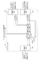
- FIG. 16 is a diagram showing the basic principle of a conventional echo canceller 10. As shown in FIG. 16, the echo canceller 10 removes the echo collected by the microphone 30 from the sound emitted from the speaker 20.
- the echo canceller 10 includes a pseudo echo generation unit 11 and a subtractor 12, and the pseudo echo generation unit 11 uses the input signal and the reference signal from the microphone 30 to connect the speaker 20 and the microphone 30. Estimate the transfer function of the arranged space. Then, the pseudo-echo generation unit 11 configures the estimated transfer function with an adaptive filter having a predetermined number of taps, and generates a pseudo-echo by driving the adaptive filter. Then, the subtracter 12 reduces the echo by subtracting the pseudo echo generated by the pseudo echo generation unit 11 from the input signal input from the microphone 30.
- the echo canceller 10 processes an E ⁇ F tap filter for each sample, the amount of calculation per unit time is (E ⁇ F) ⁇ F. That is, the calculation amount of the echo canceller 10 is proportional to the echo reverberation time E and proportional to the square of the sampling frequency F.
- Non-Patent Document 1 There is a sub-band echo canceller as a known technique for reducing the amount of computation of an echo canceller that cancels echoes in a space where a speaker and a microphone are set apart from each other (see Non-Patent Document 1).
- the input signal is divided into a plurality of subband signals and simultaneously downsampled. For example, if the signal is divided into 20 subbands and 1/16 downsampling is performed, the amount of calculation is E ⁇ (F / 16) ⁇ (F / 16) ⁇ 20 + ⁇ . ⁇ is a calculation amount for subband division. If ⁇ is sufficiently small, the amount of calculation can be reduced to 20/256 compared to a normal echo canceller.
- Patent Document 1 discloses a technique for reducing the amount of calculation in a subband echo canceller by increasing or decreasing the number of taps of the adaptive filter of the echo canceller of each band according to the sound source. Has been.
- the above conventional technique has a problem that the amount of calculation of the echo canceller is not sufficiently reduced.
- the calculation amount of the echo canceller is 180 times different between the conventional mobile phone and the highly realistic communication system. Compared to the case of a mobile phone, the increase in the calculation amount is 180 ⁇ 20 / 256 ⁇ 14 times.
- the present invention has been made in view of the above-described conventional problems, and an object thereof is to provide a communication terminal and a communication method that can further reduce the amount of calculation required for echo cancellation processing.
- a communication terminal is a communication terminal that performs voice signal communication with another communication terminal, and the input bit received from the other communication terminal.
- An output audio signal is generated by decoding the stream, and the input audio signal collected by a decoding unit that outputs the generated output audio signal to a speaker and a microphone installed in a space where the speaker outputs sound is acquired.
- An echo cancellation unit that generates a transmission audio signal by removing an echo component included in the acquired input audio signal and corresponding to the output audio signal generated by the decoding unit for each subband; and the transmission audio An encoding unit that generates an output bitstream by encoding the signal and transmits the generated output bitstream to the other communication terminal; and the output audio signal and the transmission In response to at least one of the regeneration zone of use audio signal, and a control unit for controlling the echo cancellation performance by the echo canceller in each subband.
- the echo cancellation processing performance is controlled according to the reproduction band of at least one of the output audio signal and the transmission audio signal, the amount of calculation required for the echo cancellation processing can be further reduced.
- the echo cancellation unit generates the transmission audio signal by applying a filter with a predetermined number of taps to the input audio signal for each subband, and the control unit generates the output audio signal and The number of taps may be set for each subband according to at least one reproduction band of the transmission audio signal.
- the control unit may set the number of filter taps to be applied to 0 in at least one subband including a frequency band equal to or higher than at least one reproduction band of the output audio signal and the transmission audio signal.
- the calculation amount can be further reduced.
- the calculation amount can be further reduced by setting so as not to perform unnecessary echo cancellation processing. it can.
- control unit may execute an echo cancellation process only on a subband including a frequency band equal to or lower than a reproduction band of at least one of the output audio signal and the transmission audio signal.
- the calculation amount can be further reduced by setting so as not to perform unnecessary echo cancellation processing. it can.
- control unit further determines a type of codec used when the other communication terminal encodes or decodes an audio signal, thereby at least one of the output audio signal and the transmission audio signal.
- a determination unit that determines a reproduction band may be provided, and the control unit may control the echo cancellation processing performance according to the reproduction band determined by the determination unit.
- the playback band can be determined simply by determining the type of codec, so the amount of computation required for echo cancellation processing can be greatly reduced compared to determining the number of taps from the input audio signal. Can do.
- the control unit further includes a determination unit that determines a reproduction band of at least one of the output audio signal and the transmission audio signal by determining a sampling frequency used by the other communication terminal, The control unit may control the echo cancellation processing performance according to the reproduction band determined by the determination unit.
- the playback band can be determined simply by determining the sampling frequency, so that the amount of computation required for echo cancellation processing can be greatly reduced compared to the case where the number of taps is determined from the input audio signal. it can.
- the input bit stream includes a parameter indicating a reproduction band of the output audio signal
- the decoding unit generates the output audio signal and the parameter by decoding the input bit stream, and the control unit Further, the echo cancellation processing performance may be controlled in accordance with a reproduction band indicated by the parameter generated by the decoding unit.
- the amount of calculation required for the echo cancellation process can be greatly reduced as compared with the case where the number of taps is determined from the input audio signal.
- control unit further determines a reproduction band of the audio signal for transmission when the calculation amount by the process executed by the communication terminal exceeds a predetermined threshold, and according to the determined reproduction band, The echo cancellation processing performance may be controlled for each subband.
- the echo cancellation process can be executed with a low amount of calculation.
- the communication terminal further includes a band limiting unit that outputs an output audio signal of a limited reproduction band to the speaker by limiting a reproduction band of the output audio signal
- the control unit further includes: When the amount of computation by the processing executed by the communication terminal exceeds a predetermined threshold, the reproduction band to be limited is determined by the band limiting unit, and the echo cancellation processing performance is set for each subband according to the determined reproduction band. You may control to.
- the echo cancellation process can be executed in this manner, so that it is possible to reduce the deterioration of the voice on the other communication terminal side.
- the communication terminal further includes a reproduction band of an audio signal used when the other communication terminal generates the input bitstream when the amount of calculation performed by the process executed by the communication terminal exceeds a predetermined threshold.
- An instruction unit for transmitting an instruction for restricting to the other communication terminal may be provided.
- the frequency band transmitted to the other communication terminal is limited by limiting the frequency band of the sound output on the communication terminal side in the other communication terminal. Therefore, the echo cancellation process can be executed with a small amount of computation, so that it is possible to reduce the deterioration of voice on the other communication terminal side.
- a communication terminal is a communication terminal that performs audio signal communication with another communication terminal, and outputs an output by decoding an input bitstream received from the other communication terminal.
- a voice signal is generated, a decoding unit that outputs the generated output voice signal to a speaker, and an input voice signal collected by a microphone installed in a space where the speaker emits sound is acquired, and the acquired input voice signal is obtained.
- An echo cancellation unit that generates a transmission audio signal by removing an echo component corresponding to the output audio signal generated by the decoding unit for each subband, and encoding the transmission audio signal.
- an encoding unit that generates an output bitstream and transmits the generated output bitstream to the other communication terminal, and an amount of calculation performed by the communication terminal, Serial echo cancellation performance by the echo canceling part A, and a control section for controlling for each sub-band.
- the echo cancellation process can be executed with a low amount of calculation.
- the echo cancellation unit generates the transmission audio signal by applying a filter with a predetermined number of taps to the input audio signal for each subband, and the control unit is configured to respond to the calculation amount.
- the number of taps may be set for each subband.
- the control unit may include a filter tap to be applied to one or more subbands including a subband including the maximum frequency band and not including the minimum frequency band when the calculation amount exceeds a predetermined threshold.
- the number may be set to zero.
- control unit when the amount of calculation exceeds a predetermined threshold, includes an echo cancellation process only in one or more subbands including a subband including the minimum frequency band and not including the maximum frequency band. May be executed.
- the present invention can be realized not only as a communication terminal but also as a method using a processing unit constituting the communication terminal as a step.
- each of the communication terminals may be configured by one system LSI (Large Scale Integration).
- the system LSI is an ultra-multifunctional LSI manufactured by integrating a plurality of components on one chip. Specifically, a microprocessor, a ROM (Read Only Memory), a RAM (Random Access Memory), etc. It is a computer system comprised including.
- the communication terminal and the communication method according to the present invention it is possible to further reduce the amount of calculation required for echo cancellation processing.
- FIG. 1 is a block diagram showing an example of a configuration of a communication terminal according to Embodiment 1.
- FIG. 2 is a block diagram illustrating an example of a detailed functional configuration of the echo canceller according to the first embodiment.
- FIG. 3 is a diagram for explaining an example of the operation of the echo canceller according to the first embodiment.
- FIG. 4 is a diagram for explaining another example of the operation of the echo canceller according to the first embodiment.
- FIG. 5 is a flowchart illustrating an example of echo cancellation processing according to the first embodiment.
- FIG. 6 is a block diagram showing another example of the configuration of the communication terminal according to Embodiment 1.
- FIG. 7 is a diagram showing an example of frequency characteristics of the output audio signal according to the first embodiment.
- FIG. 8 is a block diagram showing another example of a detailed functional configuration of the echo canceller according to the first embodiment.
- FIG. 9 is a block diagram showing another example of the configuration of the communication terminal according to Embodiment 1.
- FIG. 10 is a block diagram illustrating an example of a configuration of a communication terminal according to the second embodiment.
- FIG. 11 is a diagram for explaining an example of the operation of the echo canceller according to the second embodiment.
- FIG. 12 is a schematic diagram for explaining the tap number changing process while maintaining the magnitude relation of the tap numbers according to the second embodiment.
- FIG. 13 is a block diagram showing another example of the configuration of the communication terminal according to Embodiment 2.
- FIG. 14 is a block diagram illustrating another example of a detailed functional configuration of the echo canceller according to the second embodiment.
- FIG. 15 is a block diagram showing another example of the configuration of the communication terminal according to Embodiment 2.
- FIG. 16 is a diagram illustrating the basic principle of a conventional echo canceller.
- the communication terminal according to Embodiment 1 is a communication terminal that communicates audio signals with other communication terminals, acquires an input audio signal collected by a microphone, and is included in the acquired input audio signal
- An echo cancel unit that generates a transmission audio signal by removing an echo component corresponding to the output audio signal output from the speaker for each subband, and at least one of the output audio signal and the transmission audio signal
- a control unit for controlling the echo cancellation processing performance according to the reproduction band. That is, the communication terminal according to Embodiment 1 controls the echo cancellation processing performance according to the reproduction band of an audio signal processed by another communication terminal, for example, an audio signal to be encoded or decoded.
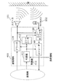
- FIG. 1 is a diagram illustrating an example of the configuration of the communication terminal 100 according to the first embodiment.
- the communication terminal 100 communicates with other communication terminals through a communication network such as the Internet with high presence such as a TV phone and a TV conference.
- the communication terminal 100 outputs an audio signal received from another communication terminal to the speaker 101 and transmits an audio signal collected by the microphone 102 to the other communication terminal.
- the communication terminal 100 includes a control unit 110, a decoder 120, an echo canceller 130, and an encoder 140.
- the control unit 110 controls the echo cancellation processing performance by the echo canceller 130 for each subband according to the output audio signal output from the decoder 120 or the reproduction band of the transmission audio signal to be encoded by the encoder 140. . That is, the control unit 110 controls the echo cancellation processing performance according to the reproduction band of the audio signal processed by another communication terminal. As shown in FIG. 1, the control unit 110 includes a determiner 111 and a controller 112.
- the determiner 111 determines the codec type of the far end (other communication terminal). Specifically, the determiner 111 encodes an audio signal by another communication terminal to generate an input bit stream received by the communication terminal 100 or an output bit stream transmitted by the communication terminal 100. Determine the type of codec to use when decoding.
- the determiner 111 determines which method of encoder the other communication terminal uses to compress and encode the audio signal.
- the type of codec is, for example, G. 729 or G.I.
- AAC Advanced Audio Coding
- AMR-WB Adaptive Multi-Rate-WideBand
- the determination unit 111 determines the reproduction band of the audio signal by determining the type of codec used by the other communication terminal. For example, if the type of codec is G. 711 and G.G. 729, the sampling frequency and the reproduction band are naturally determined by the standard. Specifically, the codec type is G. 711 and G.G. In the case of 729, the sampling frequency of the input signal to the encoder is 8 kHz, and the reproduction band is 4 kHz.
- the determiner 111 determines the reproduction band of the audio signal by determining the sampling frequency used in another communication terminal. Since the reproduction band is basically 1 ⁇ 2 of the sampling frequency, the determiner 111 can determine the reproduction band by acquiring information indicating the sampling frequency from another communication terminal.
- the determiner 111 determines which decoding method can be used by other communication terminals. For example, the determiner 111 is configured such that the other communication terminal is G.264. 711 or G.711. It is determined whether the 729 method can be used. Further, the determination unit 111 determines how many kHz sampling frequency can be used when other communication terminals can use AMR-WB or AAC.
- the determiner 111 determines the reproduction band of the audio signal by determining the codec type and / or sampling frequency used by other communication terminals during encoding or decoding.
- the reproduction band of the audio signal is the reproduction band of the output audio signal output from the decoder 120 or the reproduction band of the transmission audio signal input to the encoder 140.
- the controller 112 controls the echo cancellation processing performance by the echo canceller 130 for each subband in accordance with the reproduction band of the output audio signal or the transmission audio signal. A specific operation of the controller 112 will be described later.
- the decoder 120 is an example of a decoding unit according to the present invention, generates an output audio signal by decoding an input bit stream received from another communication terminal, and outputs the generated output audio signal to the speaker 101. Specifically, the decoder 120 decodes the input bitstream using the type of codec determined by the determiner 111.
- the speaker 101 converts the output audio signal output from the decoder 120 into an audible signal, and outputs the converted audible signal in space.
- the space is a space in which the speaker 101 and the microphone 102 are arranged, and is a space within a range in which an audible signal output from the speaker 101 is collected by the microphone 102.
- the microphone 102 picks up the near-end (communication terminal 100) side sound including the audible signal output from the speaker 101.
- An input voice signal that is a voice signal picked up by the microphone 102 is output to the echo canceller 130.
- the input audio signal includes an echo component corresponding to the output audio signal generated by the decoder 120.
- the echo component includes a signal picked up directly by the microphone 102 from the speaker 101 and a signal picked up by the microphone 102 after being reflected from the speaker 101 to the wall or the like.
- the echo canceller 130 is an example of an echo cancellation unit according to the present invention, and generates a transmission audio signal by removing an echo component included in the input audio signal for each subband.
- the operation of the echo canceller 130 is controlled by the controller 112 for each subband. A specific configuration and operation of the echo canceller 130 will be described later.
- the encoder 140 is an example of an encoding unit according to the present invention, generates an output bit stream by encoding a transmission audio signal, and transmits the generated output bit stream to another communication terminal. Specifically, the encoder 140 encodes the input bitstream using the type of codec determined by the determiner 111. That is, the encoder 140 acquires information indicating the type of decoder provided on the far end side (other communication terminal) by the determiner 111, and selects an appropriate encoder from the types indicated by the acquired information.
- FIG. 2 is a block diagram illustrating an example of a detailed functional configuration of the echo canceller 130 according to the first embodiment.
- the input signal to the echo canceller 130 includes a PCM signal (reference signal (ie, output audio signal)) from the decoder 120, a PCM signal (input audio signal) from the microphone 102, and a control signal from the controller 112. It is.
- the output signal (transmission audio signal) from the echo canceller 130 is a PCM signal to the encoder 140.
- the sampling frequency of the reference signal is 24 kHz (reproduction band is 12 kHz)
- the sampling frequency of the signal from the microphone 102 is 24 kHz (reproduction band is 12 kHz)
- the sampling frequency of the signal to the encoder 140 is 24 kHz.
- the echo canceller 130 includes subband division filters 131 and 132, pseudo echo generation units 133a to 133f, subtractors 134a to 134f, and a subband synthesis filter 135.
- the subband division filter 131 divides the PCM signal (output audio signal) input from the decoder 120 into a plurality of bands (a plurality of subbands) and downsamples the PCM signal.
- the band-divided signal is output to the pseudo echo generators 133a to 133f for each frequency band (for each subband).
- the sub-band division filter 132 divides the PCM signal (input audio signal) input from the microphone 102 into a plurality of bands (a plurality of sub-bands) and down-samples.
- the band-divided signal is output to the pseudo echo generators 133a to 133f for each frequency band (for each subband).
- the number of band divisions of the subband division filter 132 and the thinning rate in downsampling are preferably equal to the number of band divisions of the subband division filter 131 and the thinning rate.
- FIG. 2 shows an example of band division into six subbands as an example, it is not limited to this.
- 16-band division or 32-band division may be used.
- the thinning rate in downsampling may be any thinning rate as long as it is the same as or smaller than the number of band divisions.
- 10 subband division 1/10 downsampling (10 decimation) or 1/8 downsampling (8 decimation) may be used.
- the pseudo echo generators 133a to 133f use the input signal from the microphone 102 and the reference signal from the decoder 120 to estimate the transfer function of the space in which the audible signal output from the speaker 101 propagates, and the transfer function Is constituted by an adaptive filter having a predetermined number of taps, and a pseudo echo is generated by driving the adaptive filter.
- the pseudo echo generators 133a to 133f configure adaptive filters for the subband signals assigned to the pseudo echo generators 133a to 133f, and generate pseudo echoes.
- any method already known in the present embodiment may be used (for example, the method described in Non-Patent Document 2 may be used).
- the pseudo echo generators 133a to 133f set the number of filter taps for each subband based on the control signal from the controller 112. A specific operation based on a control signal from the controller 112 will be described later.
- the subtracters 134a to 134f reduce the echoes by subtracting the pseudo echoes generated by the pseudo echo generation units 133a to 133f from the input signal from the microphone 102.
- the subband synthesis filter 135 band-synthesizes the signal for each subband from which echo is removed as described above, and generates a time-speech transmission audio signal.
- the controller 112 controls the echo cancellation processing performance by the echo canceller 130 based on the reproduction band of the output audio signal, that is, the reproduction band of the audio signal encoded at the far end (other communication terminal).
- FIG. 3 is a diagram illustrating an example of a functional configuration of the echo canceller 130 when the sampling frequency of the output audio signal input from the decoder 120 is 8 kHz and the sampling frequency of the transmission audio signal output to the encoder 140 is 24 kHz. .
- the far-end encoder is, for example, G. 711, and occurs when the determination unit 111 determines that the far-end decoder is in the 24 kHz mode of AMR-WB, for example.
- the controller 112 controls the echo canceller 130 to process a subband signal in a band from 0 to 12 kHz. .
- the input audio signal is band-divided into six subbands by the subband division filter 132.
- the sampling frequency of the output audio signal (reference signal) from the decoder 120 is 8 kHz, that is, the reproduction band of the output audio signal is up to 4 kHz, among the input audio signals input from the microphone 102.
- the frequency band of the echoes included in is also 4 kHz or less. Therefore, only two subbands (0 to 2 kHz and 2 to 4 kHz) need to be subjected to echo cancellation processing.
- the controller 112 performs control so as not to perform echo cancellation processing in a subband higher than 4 kHz. That is, the controller 112 sets the number of filter taps of the pseudo echo generators 133c to 133f that process subbands of frequency components higher than 4 kHz to 0. Alternatively, the controller 112 may set the number of taps to a sufficiently small value so that the calculation amount can be ignored.
- the controller 112 sets the number of taps of the high frequency echo cancellation filter to the number of taps of the low frequency echo cancellation filter. You may set smaller than a number. That is, in this embodiment, since the echo cancellation processing is performed in the two low-frequency subbands, the controller 112 determines the number of taps of the filter in the 0 to 2 kHz band applied by the pseudo echo generation unit 133a as the pseudo echo generation. It may be set larger than the number of taps of the 2 to 4 kHz band filter applied by the unit 133b.
- the controller 112 causes the echo cancellation process to be executed only for the reproduction band of the output audio signal, that is, the subband including the frequency band equal to or less than the reproduction band of the audio signal encoded on the far end side.
- the controller 112 sets the number of filter taps to be applied to 0 in at least one subband including a frequency band equal to or higher than the reproduction band of the output audio signal.
- the number of filter taps to be applied is set to 0 in all subbands including a frequency band equal to or higher than the reproduction band of the output audio signal.
- the frequency band of the signal transmitted to the far end side is not impaired, and the echo cancellation processing can be performed only in the necessary minimum band, so that the communication terminal with a low calculation amount and high sound quality can be performed. And a communication method can be provided.
- FIG. 4 shows that the sampling frequency of the output audio signal (the signal encoded at the far end) input from the decoder 120 is 24 kHz, and the sampling frequency of the transmission audio signal (the signal decoded at the far end) output to the encoder 140. It is a figure which shows an example of a function structure of the echo canceller 130 when is 8 kHz.
- the reproduction band of the output audio signal is 12 kHz
- the frequency band of the echo included in the input audio signal input from the microphone 102 is also included in 12 kHz or less.
- the echo cancellation processing may be a band of 4 kHz or less. That is, the controller 112 sets the number of filter taps of the pseudo echo generators 133c to 133f that process subbands of frequency components higher than 4 kHz to 0 (or a sufficiently small value).
- the above is the same as that shown in FIG. 3, except that the input to the subband synthesis filter 135 is only an echo-cancelled signal. This is because the high frequency component cannot be reproduced on the far end side, and it is meaningless to band-synthesize the high frequency component.
- the control unit 110 causes the echo cancellation process to be performed only on the subband including the frequency below the reproduction band of the transmission audio signal, that is, the reproduction band of the audio signal decoded on the far end side.
- the control unit 110 sets the number of filter taps to be applied to 0 in at least one subband including a frequency band equal to or higher than the reproduction band of the transmission audio signal.
- control unit 110 sets the number of filter taps to be applied to 0 in all subbands including a frequency band equal to or higher than the reproduction band of the transmission audio signal.
- control unit 110 compares the reproduction band of the output audio signal and the reproduction band of the transmission audio signal, and determines whether to perform the echo cancellation processing based on the smaller reproduction band. Also good.
- the input audio signal does not include echoes in the frequency band above the playback band of the output audio signal. It is sufficient to perform the echo cancellation processing only on the subband including the band. Also, if the transmission band of the transmission audio signal is smaller than the reproduction band of the output audio signal, even if echo cancellation processing is performed in a frequency band that is higher than the reproduction band of the transmission audio signal, it is not transmitted to the far end side. It does not make sense, and it is sufficient to perform echo cancellation processing only on subbands including a frequency band equal to or lower than the reproduction band of the transmission audio signal.
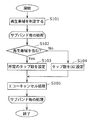
- FIG. 5 is a flowchart illustrating an example of echo cancellation processing according to the first embodiment.
- the determiner 111 determines the reproduction band of the output audio signal and the transmission audio signal (S101). Specifically, as described above, the determiner 111 determines the reproduction band by acquiring the codec type and sampling frequency of the encoder and decoder used at the far end (other communication terminals).
- controller 112 and the echo canceller 130 repeat the following processing for each subband.
- the controller 112 and the echo canceller 130 execute in order from the low-frequency subband.
- the controller 112 determines whether or not the subband includes the reproduction band (S102). For example, when the subband includes the reproduction band, such as the 0 to 2 kHz subband shown in FIG. 3 or FIG. 4 (Yes in S102), the controller 112 sets the echo canceller to set a predetermined number of taps. 130 is controlled (S103). At this time, the predetermined number of taps may be a predetermined fixed value.
- the controller 112 sets the echo canceller to set the number of taps to zero. 130 is controlled (S104).
- the echo canceller 130 executes an echo cancellation process by applying a filter with the set number of taps to the input audio signal subjected to the band division (S105).
- processing for each subband may be executed sequentially as in the flowchart shown in FIG. 5 or may be executed in parallel processing.
- the communication terminal 100 according to Embodiment 1 can reduce the amount of processing by controlling the handling of subband signals according to the processing capability on the far end side. Specifically, the communication terminal 100 according to Embodiment 1 determines the reproduction band of the audio signal processed by the other communication terminal from the type or sampling frequency of the codec used by the other communication terminal, and performs the reproduction. By controlling the echo cancellation processing performance based on the band, the amount of computation required for the echo cancellation processing can be reduced.
- the reproduction band is specified as a sampling frequency that can be directly specified from the type of codec determined by the determiner 111 or a sampling frequency of a signal at the time of encoding, and 1 / of the sampling frequency.
- the playback band was specified as 2.
- the reproduction band may not be accurately determined from the sampling frequency, but may be accurately determined by parameters included in the input bitstream.
- FIG. 6 is a block diagram showing another example of the configuration of the communication terminal according to the first embodiment.
- the communication terminal 200 shown in FIG. 6 is different from the communication terminal 100 shown in FIG. 1 in that a control unit 210 is provided instead of the control unit 110 and a decoder 220 is provided instead of the decoder 120.
- the control unit 210 is different in that the controller 212 is provided instead of the controller 112 and the determination unit 111 is not provided.
- description of the same points as in FIG. 1 will be omitted, and different points will be mainly described.
- the decoder 220 is an example of a decoding unit according to the present invention, and generates an output audio signal and a parameter by decoding an input bitstream including a parameter indicating a reproduction band of the output audio signal.
- an input bit stream encoded by the AAC method includes a parameter “max_sfb” indicating the upper limit of the reproduction band. Therefore, the decoder 220 outputs the parameter “max_sfb” to the controller 212 by decoding the input bit stream.
- the controller 212 acquires the parameter “max_sfb” from the decoder 220 and determines that the value indicated by the acquired “max_sfb” is the upper limit of the reproduction band. Then, the controller 212 controls the echo canceller 130 according to the determined reproduction band. The control of the echo canceller 130 at this time is the same as the operation performed by the controller 112 shown in FIG.
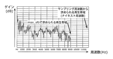
- FIG. 7 is a diagram showing an example of the frequency characteristic of the output audio signal. As shown in FIG. 7, the relationship between the reproduction band (Nyquist frequency) obtained from the sampling frequency and the reproduction band obtained from “max_sfb” is shown.
- the reproduction band obtained from the sampling frequency is 12 kHz
- the reproduction band obtained from “max_sfb” is 9 kHz. Therefore, since the echo is not included in the 9 to 12 kHz band of the input audio signal input from the microphone 102, the controller 212 sets the number of filter taps of the pseudo echo generation unit 133f shown in FIG.
- the amount of computation required for the echo cancellation process is reduced by setting the number of filter taps applied by the controller 112 or 212 when generating the pseudo echo to, for example, 0.
- the echo canceller 230 according to the modification of the first embodiment may have a function of switching whether or not to perform the echo cancellation processing for each subband.
- FIG. 8 is a diagram illustrating another example of a detailed functional configuration of the echo canceller 130 according to the first embodiment.
- the echo canceller 230 is different from the echo canceller 130 shown in FIG. 2 in that it newly includes switches 136a to 136f. In the following, description of the same points as in FIG. 2 will be omitted, and different points will be mainly described.
- the switches 136a to 136f are connected between the subband division filter 132 and each of the pseudo echo generation units 133a to 133f, respectively. Is switched based on a control signal (not shown) from the controller 112. That is, the switches 136a to 136f switch whether to execute the echo cancellation process for each subband.
- the controller 112 sets the control signal so as to turn on only the switch connected to the pseudo echo generation unit that processes the subband including the frequency band equal to or lower than the reproduction band of the output audio signal or the transmission audio signal. Output. That is, in the example shown in FIG. 3 or FIG. 4, the controller 112 turns on only the switches 136a and 136b and turns off the switches 136c to 136f.
- the echo canceller 230 according to the modification according to the first embodiment can perform the minimum necessary echo cancellation processing, the amount of calculation required for the echo cancellation processing can be reduced.
- the echo canceller 130 uses a technique for estimating the sound transmission characteristics between the speaker 101 and the microphone 102 by using an adaptive filter.
- the estimation of the transfer function by the adaptive filter cannot catch up and the echo cannot be removed as intended, or in the worst case, the howling phenomenon occurs. It is thought that it occurs.
- a videophone terminal that simultaneously transmit and receive not only audio signals but also video signals.
- a videophone terminal or the like it may be configured as a module in which a video camera and an audio microphone are integrated. In this case, it is possible to estimate whether or not the module is moving by analyzing the signal received by the video camera.
- the module itself is moving, that is, the positional relationship between the microphone 102 and the speaker 101 is changing. It is expected that In such a case, the echo cannot be removed, and howling may occur in the worst case. Therefore, the voice communication itself may be controlled to be stopped.
- FIG. 9 is a block diagram showing another example of the configuration of the communication terminal 100 according to the first embodiment.
- the microphone 102 constitutes a module 304 together with the camera 303.
- 9 is different from the communication terminal 100 shown in FIG. 1 in that a control unit 310 is provided instead of the control unit 110.
- the control unit 310 is different in that the determination unit 311 is provided instead of the determination unit 111.
- description of the same points as in FIG. 1 will be omitted, and different points will be mainly described.
- the determiner 311 acquires the video signal itself from the video camera 303 or information obtained from the signal from the camera 303, and the module 304 including the camera 303 and the microphone 102 is moving from the signal or information. It is determined whether or not. For example, if the determination unit 311 determines that the entire image is moving by performing motion detection processing on the transmitted video signal, it determines that the module 304 is moving.
- the determiner 311 performs control so as to stop the voice communication. For example, the determiner 311 stops the encoding process by the encoder 140 and the echo cancellation process by the echo canceller 130.
- the communication terminal 300 determines whether the module 304 in which the microphone 102 and the camera 303 are integrated is moving based on the video signal from the camera 303. Determine and stop inappropriate voice communication based on the determination result. For this reason, it is possible to prevent transmission of an audio signal in which echo cancellation has not been performed correctly or a signal in which howling has occurred to the far end side.
- the microphone 102 may include a sensor such as an acceleration sensor to detect movement, and the determiner 311 may stop voice communication based on information from the sensor.
- the codec type, the sampling frequency, the number of band divisions, and the downsampling rate are only examples, and these may be any values.
- the communication terminal according to Embodiment 2 is a communication terminal that communicates audio signals with other communication terminals, acquires an input audio signal collected by a microphone, and is included in the acquired input audio signal The echo component corresponding to the output audio signal output from the speaker is removed for each subband, and the echo cancellation unit that generates the audio signal for transmission and the amount of calculation by the processing executed by the communication terminal And a control unit for controlling the echo cancellation processing performance.
- FIG. 10 is a block diagram showing an example of the configuration of the communication terminal 400 according to the second embodiment.
- a communication terminal 400 shown in FIG. 10 is different from the communication terminal 100 shown in FIG. 1 in that a control unit 410 is provided instead of the control unit 110.
- description of the same points as in FIG. 1 will be omitted, and different points will be mainly described.
- the control unit 410 controls the echo cancellation processing performance by the echo canceller 130 for each subband in accordance with the amount of computation by the processing executed by the communication terminal 400. As shown in FIG. 10, the control unit 410 includes a determiner 411 and a controller 412.
- the determiner 411 determines whether or not the amount of calculation by the process executed by the communication terminal 400 exceeds a predetermined threshold. Specifically, the determiner 411 acquires processor calculation load information indicating the state of the processor calculation load, and determines whether the calculation amount of the processor exceeds a predetermined threshold based on the acquired processor calculation load information. To do.
- the processor is an arithmetic unit that actually processes each process performed by the communication terminal 400. Specifically, the processor executes the processes of the decoder 120, the echo canceller 130, the encoder 140, the determiner 411, and the controller 412.
- Processor calculation load information is information indicating the load state of functions being processed simultaneously by the processor, for example.
- the communication terminal 400 is a so-called videophone terminal that simultaneously transmits and receives a video signal, for example, a usage state (function of the function) of performing communication by a videophone system on a sub-screen while watching a TV broadcast on the main screen. Congested state).
- the calculation load on the processor increases, and as a result, the calculation amount allocated to the echo canceller 130 and the encoder 140 is compressed. In such a case, the amount of calculation is reduced by selecting a codec with a low calculation load among the codecs that can be processed on the far end side.
- the predetermined threshold value may be a predetermined fixed value. Alternatively, it may be dynamically determined according to the amount of computation of other processing required by the processor.
- the determiner 411 determines the audio signal by determining the type and / or sampling frequency of the codec that other communication terminals use when encoding or decoding.
- the playback band may be determined.
- the controller 412 controls the echo cancellation processing performance by the echo canceller 130 for each subband according to the amount of calculation by the processing executed by the communication terminal 400. Specifically, the controller 412 controls the echo cancellation processing performance when the determination unit 411 determines that the calculation amount exceeds a predetermined threshold. Specific operation of the controller 412 will be described later.
- the controller 412 controls the reproduction band of a transmission audio signal to be transmitted to another communication terminal because the calculation amount of the processor increases and exceeds a predetermined threshold.
- the sampling frequency of the PCM signal (output audio signal) from the decoder 120 and the sampling frequency of the PCM signal (input audio signal) from the microphone 102 are both 24 kHz (reproduction band is 12 kHz).
- 2 is a diagram illustrating an example of a functional configuration of an echo canceller 130.
- the determination unit 411 determines that the decoding method that can be processed on the far end side (another communication terminal) is the sampling frequency mode of 8 kHz to 24 kHz of AAC.
- the sampling frequency of both the PCM signal from the decoder 120 and the PCM signal from the microphone 102 is 24 kHz
- high-quality communication may be performed using the AAC 24 kHz sampling frequency mode.
- the controller 412 controls the echo canceller 130 to use the AAC 16 kHz sampling frequency mode.
- the controller 412 instructs the echo canceller 130 on the subband and the number of taps to perform echo cancellation processing when the determination unit 411 determines that the amount of computation of the processor exceeds a predetermined threshold.
- the sampling frequency is 16 kHz (that is, the reproduction band is 8 kHz)
- the number of taps sufficiently necessary for removing the echo is used as the number of taps of the filters of the pseudo echo generators 133a to 133d.
- the number of filter taps of the pseudo echo generators 133e and 133f is set to zero.
- control unit 410 reduces the reproduction band of the audio signal for transmission to be transmitted to other communication terminals when the amount of computation of the processor exceeds a predetermined threshold. Accordingly, control unit 410 sets the number of filter taps applied to the subbands that are no longer transmitted to 0 (or a sufficiently small value).
- the number of taps of the filters applied to each subband (the filters of the pseudo echo generation units 133a to 133d) is all equal has been described, but the number of filter taps may be different for each subband. .
- the low-band sub-band signal has a large influence on the echo, so a long tap length is maintained.
- the high-band signal has a small influence on the echo.
- the processing may be reduced by shortening the tap length.
- the size of the shaded area in the pseudo echo generator for each subband indicates the number of taps of the filter.
- control unit 410 may set the number of taps in advance so that the number of taps becomes larger or equal in the lower subbands regardless of the amount of calculation. At this time, the control unit 410 may change the number of taps when the calculation amount exceeds a predetermined threshold value or according to the reproduction band of the output audio signal or the transmission audio signal.
- the controller 412 keeps the magnitude relationship of the number of taps for each subband before and after the change, and the controller 412 reduces the number of taps for each subband so that the number of taps becomes small. May be set. In other words, the number of taps may be set so that the number of filter taps applied to the low-frequency subband is greater than the number of filter taps applied to the high-frequency subband before and after the change.
- the frequency processed by the encoder 140 or the number of taps of the echo canceller 130 is changed.
- the far end side (other communication terminals)
- the far end side Will affect the sound quality of the audio sent.
- a method of limiting the playback band of the playback sound on the near end side may be used.
- FIG. 13 is a block diagram showing another example of the configuration of the communication terminal according to the second embodiment.
- a communication terminal 500 shown in FIG. 13 is different from the communication terminal 400 of FIG. 10 in that a control unit 510 is provided instead of the control unit 410 and a band limiter 560 is newly provided.
- the controller 510 is different in that a controller 512 is provided instead of the controller 412.
- description of the same points as in FIG. 10 will be omitted, and different points will be mainly described.
- the band limiter 560 is an example of a band limiting unit according to the present invention, and outputs an output audio signal in the limited reproduction band to the speaker 101 by limiting the reproduction band of the output audio signal.
- the band limiter 560 may attenuate a high-frequency signal with a low-pass filter based on control from the controller 512, or may decrease the sampling frequency itself with a down-sampler.
- the controller 512 determines a reproduction band to be limited by the band limiter 560 when the calculation amount of the processor exceeds a predetermined threshold, and controls the echo cancellation processing performance according to the determined reproduction band.
- the specific control of the echo cancellation processing performance is the same as that of the controller 112 described above.
- FIG. 14 is a diagram illustrating an example of a functional configuration of the echo canceller 130 when the band is limited to 8 kHz.
- the band input to the subband synthesis filter 135 is limited to 0 to 8 kHz in FIG. 11, whereas in FIG. 14, the signal in a wider band (0 to 12 kHz) Is entered. Further, in both FIG. 14 and FIG. 11, the pseudo echo generation processing is not performed on the high frequency signal (8 to 12 kHz).
- the reproduction band of the output audio signal output from the speaker 101 is limited by the band limiter 560, so that it is known that there is no high-frequency component in the echo that wraps around in space. By doing so, the frequency band of the voice transmitted to the far end is maintained at a high band, so that it is possible to provide a good voice to the far end viewer, and at the communication terminal 600 The calculation amount of the echo cancellation process can be reduced.
- the band limiter 560 is provided as a method for limiting the reproduction band of the output audio signal.
- the decoder 120 decodes the input bitstream, the high band may be discarded. . That is, the decoder 120 may decode only the low band of the input bitstream.
- a communication terminal 600 shown in FIG. 15 is different from the communication terminal 400 shown in FIG. 10 in that it includes a control unit 510 instead of the control unit 410 and a new instruction unit 670. In the following, description of the same points as in FIG. 10 will be omitted, and different points will be mainly described.
- the instruction unit 670 gives an instruction to limit the reproduction band of the audio signal used when another communication terminal generates the input bit stream when the calculation amount of the processor exceeds a predetermined threshold. Send to. Specifically, instructing unit 670 transmits an instruction for setting the reproduction band determined by control unit 510 to the reproduction band used by the encoders of other communication terminals.
- the frequency band of the voice transmitted from the communication terminal 600 to the other communication terminal is maintained as a high band, it is possible to provide good voice to the viewer on the other communication terminal side, The amount of computation of echo cancellation processing in the communication terminal 600 can be reduced.
- the processor calculation load information may be information indicating the reverberation characteristics in the room where the speaker 101 and the microphone 102 are arranged, for example. Or the information which shows the reverberation characteristic assumed in the room where the speaker 101 and the microphone 102 are arrange
- positioned may be sufficient.
- the communication terminal 400 according to Embodiment 2 obtains information indicating the reverberation characteristic in the room by generating an impulse sound from the speaker 101 and measuring the reverberation characteristic with respect to the impulse sound.
- the tap length for generating the pseudo echo must be long, but this imposes pressure on the amount of computation given to the codec.
- a codec with a low sampling frequency among the codecs that can be processed on the far end side not only can the amount of calculation of encoding be reduced, but also the number of bands and taps of the echo canceller can be reduced. it can.
- the reverberation characteristic when the reverberation characteristic is short, it is considered that there are few echo components included in the input audio signal, so the number of filter taps and the number of subbands for executing echo cancellation may be reduced.
- the control of the echo canceller 130 described above or the output audio is based only on the calculation amount of the processor of the communication terminal 400 according to the second embodiment.
- Band limitation of the signal or the audio signal for transmission may be performed.
- the control unit 410 performs echo cancellation processing only on one or more subbands including a subband including the minimum frequency band and not including the maximum frequency band. May be executed.
- the control unit 410 may set the number of filter taps applied to one or more subbands including a subband including the maximum frequency band and not including the minimum frequency band to zero.
- the echo cancellation processing is performed on at least the subband including the minimum frequency band. This is because it is desirable.
- the present invention may be realized not only as a communication terminal and a communication method, but also as a program for causing a computer to execute the communication method of the present embodiment. Further, it may be realized as a computer-readable recording medium such as a CD-ROM for recording the program. Furthermore, it may be realized as information, data, or a signal indicating the program. These programs, information, data, and signals may be distributed via a communication network such as the Internet.
- the constituent elements constituting the communication terminal may be constituted by one system LSI.
- the system LSI is an ultra-multifunctional LSI manufactured by integrating a plurality of components on a single chip.
- the system LSI is a computer system including a microprocessor, a ROM, a RAM, and the like. .
- the communication terminal and the communication method according to the present invention can reduce the amount of computation required for echo cancellation, and can be used for various communication devices such as a TV phone or a TV conference communication terminal. it can.
Landscapes
- Engineering & Computer Science (AREA)
- Signal Processing (AREA)
- Computer Networks & Wireless Communication (AREA)
- Telephone Function (AREA)
- Cable Transmission Systems, Equalization Of Radio And Reduction Of Echo (AREA)
Abstract
The disclosed communication terminal (100), which communicates an audio signal, is provided with: a decoder (120) that generates an output audio signal by decoding an input bitstream received from another communication terminal, and that outputs the generated output audio signal to a speaker; an echo canceller (130) that acquires an input audio signal acquired by means of a microphone (102) installed in the space where the speaker (101) is outputting sound, and for each sub-band, eliminates echo components that are included in the acquired audio signal and that correspond to the output audio signal, thereby generating a transmission audio signal; an encoder (140) that generates an output bitstream by encoding the transmission audio signal, and transmits the generated output bitstream to another communication terminal; and a control unit (110) that controls echo-cancelling processing performance for each sub-band in accordance with a replay band of at least one of the output audio signal and the transmission audio signal.
Description
本発明は、音声信号の送受信を行う通信端末及び通信方法に関し、特に、エコーキャンセル処理を実施した音声信号を送信する通信端末及び通信方法に関する。
The present invention relates to a communication terminal and communication method for transmitting and receiving audio signals, and more particularly to a communication terminal and communication method for transmitting audio signals subjected to echo cancellation processing.
近年、大画面の映像と高帯域の音声とを送受信することで、高品質で臨場感あふれる通信、通話が楽しめる機器の開発が行われている。この場合、音声は、映像を表示するディスプレイに内蔵されているスピーカから出音される場合が多い。また、このような機器が設置されている場所は、例えば、オフィスの会議室、住居内の居間、又は、少なくとも数人の人数が集まれるだけの容積を持った部屋であることが予想される。
In recent years, devices that can enjoy high-quality, realistic communication and calls by transmitting and receiving large-screen video and high-bandwidth audio have been developed. In this case, audio is often output from a speaker built in a display that displays video. In addition, the place where such devices are installed is expected to be, for example, an office meeting room, a living room in a house, or a room having a volume sufficient for at least several people to gather.
そのような場合、遠端(相手先の通信端末)の音声信号を出音するスピーカの音が、近端(自端末)のマイクロホンによって収音され、遠端にエコーとなって送信される。このエコーを除去するために、通信端末は、エコーキャンセラを備えている。ここでのエコーキャンセラは、スピーカとマイクロホンとが、携帯電話の場合と比べて離れた位置に設置されている場合に生じるエコーを除去する。
In such a case, the sound of the speaker that outputs the audio signal of the far end (the communication terminal of the other party) is collected by the microphone of the near end (own terminal) and transmitted as an echo to the far end. In order to remove this echo, the communication terminal includes an echo canceller. The echo canceller here removes echoes that are generated when the speaker and the microphone are installed at positions separated from each other as compared with the case of the mobile phone.
しかしながら、上記のエコーキャンセラは、従来の携帯電話で用いられているような簡易なエコーキャンセラと比較して、膨大な演算量を有するものになる。その要因としては2点ある。
However, the above echo canceller has an enormous amount of calculation compared to a simple echo canceller used in a conventional mobile phone. There are two factors.
まず1点目は、高品質な音声の送受信を行うために、音声の再生帯域が広帯域化されることである。携帯電話の場合、再生帯域は4kHz弱であるが、高臨場感の通信で用いられる音声の再生帯域は、例えば、12kHzなどである。
First, the first point is that the audio playback band is widened in order to transmit and receive high-quality audio. In the case of a cellular phone, the reproduction band is a little less than 4 kHz, but the reproduction band of audio used in high-realistic communication is, for example, 12 kHz.
2点目は、エコーの残響時間が長時間化されることである。従来の携帯電話では、音声は、耳元のスピーカから出音され、口元のマイクロホンで収音されるので、想定されるエコーの残響時間は、せいぜい30msec程度である。これに対して、高臨場感の通信システムの場合、先にも述べた通り、スピーカはディスプレイに内蔵されている大音量のスピーカであり、マイクロホンは室内に設置されている。そして、当該室内は、少なくとも数人の人数を収容できる容積を持っているので、想定されるエコーの残響時間は、600msec程度となる。
The second point is that the echo reverberation time is prolonged. In a conventional mobile phone, sound is emitted from a speaker at the ear and picked up by a microphone at the mouth, so that the expected echo reverberation time is about 30 msec at most. On the other hand, in the case of a highly realistic communication system, as described above, the speaker is a loud speaker built in the display, and the microphone is installed indoors. And since the said room has a capacity | capacitance which can accommodate at least several persons, the reverberation time of the assumed echo will be about 600 msec.
一般的に、エコーキャンセラの演算量は、同一のエコーキャンセル方式であれば、再生帯域の2乗に比例し、さらに、想定しているエコー残響時間に比例する。上記の例でいえば、再生帯域が3倍、エコーの残響時間が20倍なので、3×3×20=180倍の演算量が必要となる。
Generally, the amount of computation of the echo canceller is proportional to the square of the reproduction band and further to the assumed echo reverberation time if the same echo cancellation method is used. In the above example, since the reproduction band is 3 times and the echo reverberation time is 20 times, a calculation amount of 3 × 3 × 20 = 180 times is required.
なお、エコーキャンセラの演算量が再生帯域の2乗に比例し、さらに、想定している残響時間に比例する理由は以下の通りである。
Note that the reason why the calculation amount of the echo canceller is proportional to the square of the reproduction band and further proportional to the assumed reverberation time is as follows.
図16は、従来のエコーキャンセラ10の基本原理を示す図である。図16に示すように、エコーキャンセラ10は、スピーカ20から出音された音のうち、マイクロホン30によって収音されたエコーを除去する。
FIG. 16 is a diagram showing the basic principle of a conventional echo canceller 10. As shown in FIG. 16, the echo canceller 10 removes the echo collected by the microphone 30 from the sound emitted from the speaker 20.
具体的には、エコーキャンセラ10は、擬似エコー生成部11と減算器12とを備え、擬似エコー生成部11は、マイクロホン30からの入力信号と参照信号とを用いて、スピーカ20及びマイクロホン30が配置された空間の伝達関数を推定する。そして、擬似エコー生成部11は、推定した伝達関数を所定のタップ数の適応フィルタで構成し、当該適応フィルタを駆動することで擬似エコーを生成する。そして、減算器12は、マイクロホン30から入力された入力信号から、擬似エコー生成部11によって生成された擬似エコーを差し引くことでエコーを削減する。
Specifically, the echo canceller 10 includes a pseudo echo generation unit 11 and a subtractor 12, and the pseudo echo generation unit 11 uses the input signal and the reference signal from the microphone 30 to connect the speaker 20 and the microphone 30. Estimate the transfer function of the arranged space. Then, the pseudo-echo generation unit 11 configures the estimated transfer function with an adaptive filter having a predetermined number of taps, and generates a pseudo-echo by driving the adaptive filter. Then, the subtracter 12 reduces the echo by subtracting the pseudo echo generated by the pseudo echo generation unit 11 from the input signal input from the microphone 30.
ここで、伝達関数を構成するフィルタのタップ数Tは、エコー残響時間をE、信号のサンプリング周波数をFとした場合、T=E×Fとなる。
Here, the number of taps T of the filter constituting the transfer function is T = E × F, where E is the echo reverberation time and F is the sampling frequency of the signal.
エコーキャンセラ10は、1サンプル毎にE×Fタップのフィルタを処理するので、単位時間当たりの演算量は、(E×F)×Fとなる。つまり、エコーキャンセラ10の演算量は、エコー残響時間Eに比例し、サンプリング周波数Fの2乗に比例する。
Since the echo canceller 10 processes an E × F tap filter for each sample, the amount of calculation per unit time is (E × F) × F. That is, the calculation amount of the echo canceller 10 is proportional to the echo reverberation time E and proportional to the square of the sampling frequency F.
スピーカとマイクロホンとが離れて設置された空間におけるエコーをキャンセルするエコーキャンセラの演算量を削減する既知の技術として、サブバンドエコーキャンセラがある(非特許文献1参照)。
There is a sub-band echo canceller as a known technique for reducing the amount of computation of an echo canceller that cancels echoes in a space where a speaker and a microphone are set apart from each other (see Non-Patent Document 1).
サブバンドエコーキャンセラでは、入力の信号を複数のサブバンド信号に分割すると同時にダウンサンプリングする。例えば、信号を20サブバンドに分割し、16分の1のダウンサンプリングを行ったとすると、演算量は、E×(F/16)×(F/16)×20+αとなる。なお、αは、サブバンド分割のための演算量である。αが、十分に小さいとすると、通常のエコーキャンセラに比べ、演算量は、20/256に削減できる。
In the subband echo canceller, the input signal is divided into a plurality of subband signals and simultaneously downsampled. For example, if the signal is divided into 20 subbands and 1/16 downsampling is performed, the amount of calculation is E × (F / 16) × (F / 16) × 20 + α. Α is a calculation amount for subband division. If α is sufficiently small, the amount of calculation can be reduced to 20/256 compared to a normal echo canceller.
また、演算量をさらに削減する方法として、特許文献1には、サブバンドエコーキャンセラにおいて、各バンドのエコーキャンセラの適応フィルタのタップを音源に応じて増減させることで演算量を少なくする技術が開示されている。
In addition, as a method for further reducing the amount of calculation, Patent Document 1 discloses a technique for reducing the amount of calculation in a subband echo canceller by increasing or decreasing the number of taps of the adaptive filter of the echo canceller of each band according to the sound source. Has been.
しかしながら、上記従来技術では、エコーキャンセラの演算量の低減が充分ではないという課題がある。
However, the above conventional technique has a problem that the amount of calculation of the echo canceller is not sufficiently reduced.
例えば、非特許文献1に記載の技術では、上記の例の場合であっても、そもそも従来の携帯電話と高臨場感の通信システムとでは、エコーキャンセラの演算量が180倍違っていたので、携帯電話の場合と比べて、演算量の増加は、180×20/256≒14倍となる。
For example, in the technique described in Non-Patent Document 1, even in the case of the above example, the calculation amount of the echo canceller is 180 times different between the conventional mobile phone and the highly realistic communication system. Compared to the case of a mobile phone, the increase in the calculation amount is 180 × 20 / 256≈14 times.
また、特許文献1に記載の技術では、各サブバンドのエコーキャンセラのフィルタの次数を適応的に(入力信号に応じて)増減させる処理自身に相応の演算量が必要となる。
In addition, in the technique described in Patent Document 1, an appropriate amount of computation is required for the process itself for adaptively increasing / decreasing the order of the filter of the echo canceller of each subband (according to the input signal).
そこで、本発明は、上記従来の課題に鑑みてなされたものであって、エコーキャンセル処理に必要な演算量をより低減する通信端末及び通信方法を提供することを目的とする。
Therefore, the present invention has been made in view of the above-described conventional problems, and an object thereof is to provide a communication terminal and a communication method that can further reduce the amount of calculation required for echo cancellation processing.
上記の課題を解決するために、本発明の一態様に係る通信端末は、他の通信端末との間で音声信号の通信を行う通信端末であって、前記他の通信端末から受信した入力ビットストリームを復号することで出力音声信号を生成し、生成した出力音声信号をスピーカに出力する復号部と、前記スピーカが出音する空間に設置されたマイクロホンによって収音された入力音声信号を取得し、取得した入力音声信号に含まれ、前記復号部が生成した出力音声信号に相当するエコー成分をサブバンド毎に除去することで、送信用音声信号を生成するエコーキャンセル部と、前記送信用音声信号を符号化することで出力ビットストリームを生成し、生成した出力ビットストリームを前記他の通信端末に送信する符号化部と、前記出力音声信号及び前記送信用音声信号の少なくとも一方の再生帯域に応じて、前記エコーキャンセル部によるエコーキャンセル処理性能をサブバンド毎に制御する制御部とを備える。
In order to solve the above-described problem, a communication terminal according to an aspect of the present invention is a communication terminal that performs voice signal communication with another communication terminal, and the input bit received from the other communication terminal. An output audio signal is generated by decoding the stream, and the input audio signal collected by a decoding unit that outputs the generated output audio signal to a speaker and a microphone installed in a space where the speaker outputs sound is acquired. An echo cancellation unit that generates a transmission audio signal by removing an echo component included in the acquired input audio signal and corresponding to the output audio signal generated by the decoding unit for each subband; and the transmission audio An encoding unit that generates an output bitstream by encoding the signal and transmits the generated output bitstream to the other communication terminal; and the output audio signal and the transmission In response to at least one of the regeneration zone of use audio signal, and a control unit for controlling the echo cancellation performance by the echo canceller in each subband.
これにより、出力音声信号及び送信用音声信号の少なくとも一方の再生帯域に応じてエコーキャンセル処理性能を制御するので、エコーキャンセル処理に必要な演算量をより低減することができる。つまり、他の通信端末で処理される音声信号の再生帯域に合わせたエコーキャンセル処理を行うことができるので、無駄なエコーキャンセル処理を行わなくてよいように制御することができ、演算量を低減することができる。
Thereby, since the echo cancellation processing performance is controlled according to the reproduction band of at least one of the output audio signal and the transmission audio signal, the amount of calculation required for the echo cancellation processing can be further reduced. In other words, it is possible to perform echo cancellation processing that matches the playback band of the audio signal processed by another communication terminal, so control can be performed so that unnecessary echo cancellation processing does not have to be performed, and the amount of computation is reduced. can do.
また、前記エコーキャンセル部は、予め定められたタップ数のフィルタを前記入力音声信号にサブバンド毎に適用することで、前記送信用音声信号を生成し、前記制御部は、前記出力音声信号及び前記送信用音声信号の少なくとも一方の再生帯域に応じて、前記タップ数をサブバンド毎に設定してもよい。
In addition, the echo cancellation unit generates the transmission audio signal by applying a filter with a predetermined number of taps to the input audio signal for each subband, and the control unit generates the output audio signal and The number of taps may be set for each subband according to at least one reproduction band of the transmission audio signal.
これにより、サブバンド毎にタップ数を適応的に設定することができるので、サブバンド毎に無駄の少ないフィルタを適用することができ、エコーキャンセル処理に必要な演算量を低減することができる。
Thereby, since the number of taps can be set adaptively for each subband, a less wasteful filter can be applied for each subband, and the amount of calculation required for echo cancellation processing can be reduced.
また、前記制御部は、前記出力音声信号及び前記送信用音声信号の少なくとも一方の再生帯域以上の周波数帯域を含む少なくとも1つのサブバンドにおいて適用するフィルタのタップ数を0に設定してもよい。
The control unit may set the number of filter taps to be applied to 0 in at least one subband including a frequency band equal to or higher than at least one reproduction band of the output audio signal and the transmission audio signal.
これにより、送信用音声信号の再生帯域以上の周波数成分は他の通信端末では処理されないので、他の通信端末に送信されても意味のない周波数帯域のサブバンドに対するエコーキャンセル処理を行わないように設定することで、演算量をより低減することができる。あるいは、入力音声信号には、出力音声信号の再生帯域以上の周波数成分のエコー成分は含まれないので、必要でないエコーキャンセル処理を行わないように設定することで、演算量をより低減することができる。
As a result, since the frequency component above the reproduction band of the audio signal for transmission is not processed by other communication terminals, echo cancellation processing is not performed on subbands of meaningless frequency bands even if transmitted to other communication terminals. By setting, the calculation amount can be further reduced. Alternatively, since the input audio signal does not include an echo component having a frequency component equal to or higher than the reproduction band of the output audio signal, the calculation amount can be further reduced by setting so as not to perform unnecessary echo cancellation processing. it can.
また、前記制御部は、前記出力音声信号及び前記送信用音声信号の少なくとも一方の再生帯域以下の周波数帯域を含むサブバンドのみに、エコーキャンセル処理を実行してもよい。
Further, the control unit may execute an echo cancellation process only on a subband including a frequency band equal to or lower than a reproduction band of at least one of the output audio signal and the transmission audio signal.
これにより、送信用音声信号の再生帯域以下の周波数成分のみが他の通信端末で処理されるので、他の通信端末に送信する周波数帯域のサブバンドのみに対するエコーキャンセル処理を行うように設定することで、演算量をより低減することができる。あるいは、入力音声信号には、出力音声信号の再生帯域以下の周波数成分のエコー成分しか含まれないので、必要でないエコーキャンセル処理を行わないように設定することで、演算量をより低減することができる。
As a result, only the frequency component below the reproduction band of the transmission audio signal is processed by the other communication terminal, so that the echo cancellation processing is performed only for the subband of the frequency band transmitted to the other communication terminal. Thus, the amount of calculation can be further reduced. Alternatively, since the input audio signal includes only the echo component of the frequency component below the reproduction band of the output audio signal, the calculation amount can be further reduced by setting so as not to perform unnecessary echo cancellation processing. it can.
また、前記制御部は、さらに、前記他の通信端末が音声信号を符号化又は復号する際に使用するコーデックの種別を判定することで、前記出力音声信号及び前記送信用音声信号の少なくとも一方の再生帯域を決定する判定部を備え、前記制御部は、前記判定部によって決定された再生帯域に応じて、前記エコーキャンセル処理性能を制御してもよい。
Further, the control unit further determines a type of codec used when the other communication terminal encodes or decodes an audio signal, thereby at least one of the output audio signal and the transmission audio signal. A determination unit that determines a reproduction band may be provided, and the control unit may control the echo cancellation processing performance according to the reproduction band determined by the determination unit.
これにより、コーデックの種別を判定するだけで、再生帯域を決定することができるので、入力音声信号からタップ数を決定する場合に比べて、エコーキャンセル処理に必要な演算量を大幅に低減することができる。
As a result, the playback band can be determined simply by determining the type of codec, so the amount of computation required for echo cancellation processing can be greatly reduced compared to determining the number of taps from the input audio signal. Can do.
また、前記制御部は、さらに、前記他の通信端末が使用するサンプリング周波数を判定することで、前記出力音声信号及び前記送信用音声信号の少なくとも一方の再生帯域を決定する判定部を備え、前記制御部は、前記判定部によって決定された再生帯域に応じて、前記エコーキャンセル処理性能を制御してもよい。
The control unit further includes a determination unit that determines a reproduction band of at least one of the output audio signal and the transmission audio signal by determining a sampling frequency used by the other communication terminal, The control unit may control the echo cancellation processing performance according to the reproduction band determined by the determination unit.
これにより、サンプリング周波数を判定するだけで、再生帯域を決定することができるので、入力音声信号からタップ数を決定する場合に比べて、エコーキャンセル処理に必要な演算量を大幅に低減することができる。
As a result, the playback band can be determined simply by determining the sampling frequency, so that the amount of computation required for echo cancellation processing can be greatly reduced compared to the case where the number of taps is determined from the input audio signal. it can.
また、前記入力ビットストリームは、前記出力音声信号の再生帯域を示すパラメータを含み、前記復号部は、前記入力ビットストリームを復号することで前記出力音声信号と前記パラメータとを生成し、前記制御部は、さらに、前記復号部によって生成されたパラメータが示す再生帯域に応じて、前記エコーキャンセル処理性能を制御してもよい。
The input bit stream includes a parameter indicating a reproduction band of the output audio signal, and the decoding unit generates the output audio signal and the parameter by decoding the input bit stream, and the control unit Further, the echo cancellation processing performance may be controlled in accordance with a reproduction band indicated by the parameter generated by the decoding unit.
これにより、パラメータに示された再生帯域を利用するので、入力音声信号からタップ数を決定する場合に比べて、エコーキャンセル処理に必要な演算量を大幅に低減することができる。
Thus, since the reproduction band indicated by the parameter is used, the amount of calculation required for the echo cancellation process can be greatly reduced as compared with the case where the number of taps is determined from the input audio signal.
また、前記制御部は、さらに、当該通信端末が実行する処理による演算量が所定の閾値を超えた場合に、前記送信用音声信号の再生帯域を決定し、決定した再生帯域に応じて、前記エコーキャンセル処理性能をサブバンド毎に制御してもよい。
Further, the control unit further determines a reproduction band of the audio signal for transmission when the calculation amount by the process executed by the communication terminal exceeds a predetermined threshold, and according to the determined reproduction band, The echo cancellation processing performance may be controlled for each subband.
これにより、演算量が増大した場合であっても、エコーキャンセル処理を低演算量で実行することができる。
Thereby, even if the amount of calculation increases, the echo cancellation process can be executed with a low amount of calculation.
また、前記通信端末は、さらに、前記出力音声信号の再生帯域を制限することで、制限された再生帯域の出力音声信号を前記スピーカに出力する帯域制限部を備え、前記制御部は、さらに、当該通信端末が実行する処理による演算量が所定の閾値を超えた場合に、前記帯域制限部によって制限する再生帯域を決定し、決定した再生帯域に応じて、前記エコーキャンセル処理性能をサブバンド毎に制御してもよい。
The communication terminal further includes a band limiting unit that outputs an output audio signal of a limited reproduction band to the speaker by limiting a reproduction band of the output audio signal, and the control unit further includes: When the amount of computation by the processing executed by the communication terminal exceeds a predetermined threshold, the reproduction band to be limited is determined by the band limiting unit, and the echo cancellation processing performance is set for each subband according to the determined reproduction band. You may control to.
これにより、演算量が増大した場合であっても、当該通信端末側で出力される音声の周波数帯域を制限することで、他の通信端末に送信する周波数帯域を制限せずに、低演算量でエコーキャンセル処理を実行することができるので、他の通信端末側での音声の劣化を低減することができる。
As a result, even if the amount of computation increases, the amount of low computation can be reduced without restricting the frequency band transmitted to other communication terminals by restricting the frequency band of the audio output on the communication terminal side. Thus, the echo cancellation process can be executed in this manner, so that it is possible to reduce the deterioration of the voice on the other communication terminal side.
また、前記通信端末は、さらに、当該通信端末が実行する処理による演算量が所定の閾値を超えた場合に、前記他の通信端末が前記入力ビットストリームを生成する際に用いる音声信号の再生帯域を制限するための指示を前記他の通信端末に送信する指示部を備えてもよい。
In addition, the communication terminal further includes a reproduction band of an audio signal used when the other communication terminal generates the input bitstream when the amount of calculation performed by the process executed by the communication terminal exceeds a predetermined threshold. An instruction unit for transmitting an instruction for restricting to the other communication terminal may be provided.
これにより、演算量が増大した場合であっても、当該通信端末側で出力される音声の周波数帯域を他の通信端末において制限させておくことで、他の通信端末に送信する周波数帯域を制限せずに、低演算量でエコーキャンセル処理を実行することができるので、他の通信端末側での音声の劣化を低減することができる。
As a result, even if the amount of computation increases, the frequency band transmitted to the other communication terminal is limited by limiting the frequency band of the sound output on the communication terminal side in the other communication terminal. Therefore, the echo cancellation process can be executed with a small amount of computation, so that it is possible to reduce the deterioration of voice on the other communication terminal side.
また、本発明の一態様に係る通信端末は、他の通信端末との間で音声信号の通信を行う通信端末であって、前記他の通信端末から受信した入力ビットストリームを復号することで出力音声信号を生成し、生成した出力音声信号をスピーカに出力する復号部と、前記スピーカが出音する空間に設置されたマイクロホンによって収音された入力音声信号を取得し、取得した入力音声信号に含まれ、前記復号部が生成した出力音声信号に相当するエコー成分をサブバンド毎に除去することで、送信用音声信号を生成するエコーキャンセル部と、前記送信用音声信号を符号化することで出力ビットストリームを生成し、生成した出力ビットストリームを前記他の通信端末に送信する符号化部と、当該通信端末が実行する処理による演算量に応じて、前記エコーキャンセル部によるエコーキャンセル処理性能をサブバンド毎に制御する制御部とを備えてもよい。
A communication terminal according to an aspect of the present invention is a communication terminal that performs audio signal communication with another communication terminal, and outputs an output by decoding an input bitstream received from the other communication terminal. A voice signal is generated, a decoding unit that outputs the generated output voice signal to a speaker, and an input voice signal collected by a microphone installed in a space where the speaker emits sound is acquired, and the acquired input voice signal is obtained. An echo cancellation unit that generates a transmission audio signal by removing an echo component corresponding to the output audio signal generated by the decoding unit for each subband, and encoding the transmission audio signal. According to an encoding unit that generates an output bitstream and transmits the generated output bitstream to the other communication terminal, and an amount of calculation performed by the communication terminal, Serial echo cancellation performance by the echo canceling part A, and a control section for controlling for each sub-band.
これにより、演算量が増大した場合であっても、エコーキャンセル処理を低演算量で実行することができる。
Thereby, even if the amount of calculation increases, the echo cancellation process can be executed with a low amount of calculation.
また、前記エコーキャンセル部は、予め定められたタップ数のフィルタを前記入力音声信号にサブバンド毎に適用することで、前記送信用音声信号を生成し、前記制御部は、前記演算量に応じて、前記タップ数をサブバンド毎に設定してもよい。
Further, the echo cancellation unit generates the transmission audio signal by applying a filter with a predetermined number of taps to the input audio signal for each subband, and the control unit is configured to respond to the calculation amount. Thus, the number of taps may be set for each subband.
これにより、サブバンド毎にタップ数を適応的に設定することができるので、エコーキャンセル処理に必要な演算量を低減することができる。
This makes it possible to adaptively set the number of taps for each subband, thereby reducing the amount of computation required for echo cancellation processing.
また、前記制御部は、前記演算量が所定の閾値を超えた場合に、最大の周波数帯域を含むサブバンドを含み、最小の周波数帯域を含まない1つ以上のサブバンドにおいて適用するフィルタのタップ数を0に設定してもよい。
The control unit may include a filter tap to be applied to one or more subbands including a subband including the maximum frequency band and not including the minimum frequency band when the calculation amount exceeds a predetermined threshold. The number may be set to zero.
これにより、エコーの影響が小さい高周波帯域でのエコーキャンセル処理を行わないようにすることで、演算量が増大した場合であっても、演算量を低減することができるとともに、エコーの影響が大きい低周波帯域でのエコーキャンセル処理を実行するので、エコーが除去された音声信号を生成することもできる。
As a result, by avoiding echo cancellation processing in a high frequency band where the influence of echo is small, the amount of calculation can be reduced and the influence of echo is large even when the amount of calculation increases. Since echo cancellation processing in the low frequency band is executed, an audio signal from which echo is removed can be generated.
また、前記制御部は、前記演算量が所定の閾値を超えた場合に、最小の周波数帯域を含むサブバンドを含み、最大の周波数帯域を含まない1つ以上のサブバンドのみに、エコーキャンセル処理を実行してもよい。
In addition, when the amount of calculation exceeds a predetermined threshold, the control unit includes an echo cancellation process only in one or more subbands including a subband including the minimum frequency band and not including the maximum frequency band. May be executed.
これにより、エコーの影響が小さい高周波帯域でのエコーキャンセル処理を行わないようにすることで、演算量が増大した場合であっても、演算量を低減することができるとともに、エコーの影響が大きい低周波帯域でのエコーキャンセル処理を実行するので、エコーが除去された音声信号を生成することもできる。
As a result, by avoiding echo cancellation processing in a high frequency band where the influence of echo is small, the amount of calculation can be reduced and the influence of echo is large even when the amount of calculation increases. Since echo cancellation processing in the low frequency band is executed, an audio signal from which echo is removed can be generated.
なお、本発明は、通信端末として実現できるだけではなく、当該通信端末を構成する処理部をステップとする方法として実現することもできる。
Note that the present invention can be realized not only as a communication terminal but also as a method using a processing unit constituting the communication terminal as a step.
また、上記の各通信端末を構成する構成要素の一部又は全部は、1個のシステムLSI(Large Scale Integration:大規模集積回路)から構成されていてもよい。システムLSIは、複数の構成部を1個のチップ上に集積して製造された超多機能LSIであり、具体的には、マイクロプロセッサ、ROM(Read Only Memory)及びRAM(Random Access Memory)などを含んで構成されるコンピュータシステムである。
Further, some or all of the constituent elements constituting each of the communication terminals may be configured by one system LSI (Large Scale Integration). The system LSI is an ultra-multifunctional LSI manufactured by integrating a plurality of components on one chip. Specifically, a microprocessor, a ROM (Read Only Memory), a RAM (Random Access Memory), etc. It is a computer system comprised including.
本発明に係る通信端末及び通信方法によれば、エコーキャンセル処理に必要な演算量をより低減することができる。
According to the communication terminal and the communication method according to the present invention, it is possible to further reduce the amount of calculation required for echo cancellation processing.
以下では、本発明に係る通信端末及び通信方法の実施の形態について、図面を参照しながら詳細に説明する。
Hereinafter, embodiments of a communication terminal and a communication method according to the present invention will be described in detail with reference to the drawings.
(実施の形態1)
実施の形態1に係る通信端末は、他の通信端末との間で音声信号の通信を行う通信端末であって、マイクロホンによって収音された入力音声信号を取得し、取得した入力音声信号に含まれ、スピーカから出音された出力音声信号に相当するエコー成分をサブバンド毎に除去することで、送信用音声信号を生成するエコーキャンセル部と、出力音声信号及び送信用音声信号の少なくとも一方の再生帯域に応じて、エコーキャンセル処理性能を制御する制御部とを備えることを特徴とする。つまり、実施の形態1に係る通信端末は、他の通信端末が処理する音声信号、例えば、エンコード又はデコード対象の音声信号の再生帯域に応じて、エコーキャンセル処理性能を制御する。 (Embodiment 1)
The communication terminal according toEmbodiment 1 is a communication terminal that communicates audio signals with other communication terminals, acquires an input audio signal collected by a microphone, and is included in the acquired input audio signal An echo cancel unit that generates a transmission audio signal by removing an echo component corresponding to the output audio signal output from the speaker for each subband, and at least one of the output audio signal and the transmission audio signal And a control unit for controlling the echo cancellation processing performance according to the reproduction band. That is, the communication terminal according to Embodiment 1 controls the echo cancellation processing performance according to the reproduction band of an audio signal processed by another communication terminal, for example, an audio signal to be encoded or decoded.
実施の形態1に係る通信端末は、他の通信端末との間で音声信号の通信を行う通信端末であって、マイクロホンによって収音された入力音声信号を取得し、取得した入力音声信号に含まれ、スピーカから出音された出力音声信号に相当するエコー成分をサブバンド毎に除去することで、送信用音声信号を生成するエコーキャンセル部と、出力音声信号及び送信用音声信号の少なくとも一方の再生帯域に応じて、エコーキャンセル処理性能を制御する制御部とを備えることを特徴とする。つまり、実施の形態1に係る通信端末は、他の通信端末が処理する音声信号、例えば、エンコード又はデコード対象の音声信号の再生帯域に応じて、エコーキャンセル処理性能を制御する。 (Embodiment 1)
The communication terminal according to
図1は、実施の形態1に係る通信端末100の構成の一例を示す図である。通信端末100は、インターネットなどの通信網を介して他の通信端末と、TV電話、TV会議などの臨場感の高い通信を行う。通信端末100は、他の通信端末から受信した音声信号をスピーカ101に出力し、また、マイクロホン102によって収音された音声信号を他の通信端末に送信する。
FIG. 1 is a diagram illustrating an example of the configuration of the communication terminal 100 according to the first embodiment. The communication terminal 100 communicates with other communication terminals through a communication network such as the Internet with high presence such as a TV phone and a TV conference. The communication terminal 100 outputs an audio signal received from another communication terminal to the speaker 101 and transmits an audio signal collected by the microphone 102 to the other communication terminal.
図1に示すように、通信端末100は、制御部110と、デコーダ120と、エコーキャンセラ130と、エンコーダ140とを備える。
As shown in FIG. 1, the communication terminal 100 includes a control unit 110, a decoder 120, an echo canceller 130, and an encoder 140.
制御部110は、デコーダ120が出力する出力音声信号、又は、エンコーダ140による符号化対象となる送信用音声信号の再生帯域に応じて、エコーキャンセラ130によるエコーキャンセル処理性能をサブバンド毎に制御する。つまり、制御部110は、他の通信端末が処理する音声信号の再生帯域に応じて、エコーキャンセル処理性能を制御する。図1に示すように、制御部110は、判定器111と、コントローラ112とを備える。
The control unit 110 controls the echo cancellation processing performance by the echo canceller 130 for each subband according to the output audio signal output from the decoder 120 or the reproduction band of the transmission audio signal to be encoded by the encoder 140. . That is, the control unit 110 controls the echo cancellation processing performance according to the reproduction band of the audio signal processed by another communication terminal. As shown in FIG. 1, the control unit 110 includes a determiner 111 and a controller 112.
判定器111は、遠端(他の通信端末)のコーデックの種別を判定する。具体的には、判定器111は、他の通信端末が音声信号を符号化することで、通信端末100が受信する入力ビットストリームを生成する際、又は、通信端末100が送信する出力ビットストリームを復号する際に使用するコーデックの種別を判定する。
The determiner 111 determines the codec type of the far end (other communication terminal). Specifically, the determiner 111 encodes an audio signal by another communication terminal to generate an input bit stream received by the communication terminal 100 or an output bit stream transmitted by the communication terminal 100. Determine the type of codec to use when decoding.
例えば、判定器111は、他の通信端末が音声信号をどの方式のエンコーダで圧縮符号化するかを判定する。コーデックの種別は、例えば、一般的によく用いられる方式として、G.729若しくはG.711、又は、近年の高音質な方式としては、AAC(Advanced Audio Coding)若しくはAMR-WB(Adaptive Multi-Rate-WideBand)といった方式がある。
For example, the determiner 111 determines which method of encoder the other communication terminal uses to compress and encode the audio signal. The type of codec is, for example, G. 729 or G.I. As a high-quality sound system in recent years, there is a system such as AAC (Advanced Audio Coding) or AMR-WB (Adaptive Multi-Rate-WideBand).
判定器111は、例えば、通信端末100が他の通信端末との通信を確立する際に、他の通信端末が使用するコーデックの種別を判定することで、音声信号の再生帯域を判定する。例えば、コーデックの種別がG.711やG.729であれば、サンプリング周波数及び再生帯域は、規格により自ずと決定される。具体的には、コーデックの種別がG.711やG.729の場合、当該エンコーダへの入力信号のサンプリング周波数は8kHzであり、再生帯域は4kHzであることが判明する。
For example, when the communication terminal 100 establishes communication with another communication terminal, the determination unit 111 determines the reproduction band of the audio signal by determining the type of codec used by the other communication terminal. For example, if the type of codec is G. 711 and G.G. 729, the sampling frequency and the reproduction band are naturally determined by the standard. Specifically, the codec type is G. 711 and G.G. In the case of 729, the sampling frequency of the input signal to the encoder is 8 kHz, and the reproduction band is 4 kHz.
一方、AACやAMR-WBといった方式の場合、複数のサンプリング周波数を選択できるので、判定器111は、コーデックの種別だけでは、音声信号の再生帯域を判定することができない。そこで、判定器111は、他の通信端末において使用されるサンプリング周波数を判定することで、音声信号の再生帯域を判定する。再生帯域は、基本的にサンプリング周波数の1/2であるので、判定器111は、サンプリング周波数を示す情報を他の通信端末から取得することで、再生帯域を判定することができる。
On the other hand, in the case of a method such as AAC or AMR-WB, a plurality of sampling frequencies can be selected, and therefore the determination unit 111 cannot determine the reproduction band of the audio signal only by the codec type. Therefore, the determiner 111 determines the reproduction band of the audio signal by determining the sampling frequency used in another communication terminal. Since the reproduction band is basically ½ of the sampling frequency, the determiner 111 can determine the reproduction band by acquiring information indicating the sampling frequency from another communication terminal.
また、判定器111は、他の通信端末がどのデコード方式を利用することが可能かを判定する。例えば、判定器111は、他の通信端末がG.711方式若しくはG.729方式を利用することが可能か否かを判定する。また、判定器111は、他の通信端末がAMR-WB若しくはAACを利用することが可能な場合は、何kHzのサンプリング周波数を利用することができるかを判定する。
Also, the determiner 111 determines which decoding method can be used by other communication terminals. For example, the determiner 111 is configured such that the other communication terminal is G.264. 711 or G.711. It is determined whether the 729 method can be used. Further, the determination unit 111 determines how many kHz sampling frequency can be used when other communication terminals can use AMR-WB or AAC.
このように判定器111は、他の通信端末が符号化時又は復号時に使用するコーデックの種別、及び/又は、サンプリング周波数を判定することで、音声信号の再生帯域を判定する。ここで、音声信号の再生帯域は、デコーダ120が出力する出力音声信号の再生帯域、又は、エンコーダ140に入力される送信用音声信号の再生帯域である。
In this way, the determiner 111 determines the reproduction band of the audio signal by determining the codec type and / or sampling frequency used by other communication terminals during encoding or decoding. Here, the reproduction band of the audio signal is the reproduction band of the output audio signal output from the decoder 120 or the reproduction band of the transmission audio signal input to the encoder 140.
コントローラ112は、出力音声信号又は送信用音声信号の再生帯域に応じて、エコーキャンセラ130によるエコーキャンセル処理性能をサブバンド毎に制御する。コントローラ112の具体的な動作については、後で説明する。
The controller 112 controls the echo cancellation processing performance by the echo canceller 130 for each subband in accordance with the reproduction band of the output audio signal or the transmission audio signal. A specific operation of the controller 112 will be described later.
デコーダ120は、本発明に係る復号部の一例であり、他の通信端末から受信した入力ビットストリームを復号することで出力音声信号を生成し、生成した出力音声信号をスピーカ101に出力する。具体的には、デコーダ120は、判定器111によって判定された種別のコーデックを用いて入力ビットストリームを復号する。
The decoder 120 is an example of a decoding unit according to the present invention, generates an output audio signal by decoding an input bit stream received from another communication terminal, and outputs the generated output audio signal to the speaker 101. Specifically, the decoder 120 decodes the input bitstream using the type of codec determined by the determiner 111.
なお、スピーカ101は、デコーダ120から出力された出力音声信号を可聴信号に変換し、変換した可聴信号を空間に出音する。なお、ここで、空間は、スピーカ101及びマイクロホン102が配置される空間であり、スピーカ101から出音された可聴信号がマイクロホン102によって収音される範囲内の空間である。
Note that the speaker 101 converts the output audio signal output from the decoder 120 into an audible signal, and outputs the converted audible signal in space. Here, the space is a space in which the speaker 101 and the microphone 102 are arranged, and is a space within a range in which an audible signal output from the speaker 101 is collected by the microphone 102.
したがって、マイクロホン102は、スピーカ101から出音された可聴信号を含む近端(通信端末100)側の音声を収音する。マイクロホン102によって収音された音声信号である入力音声信号は、エコーキャンセラ130に出力される。なお、入力音声信号は、デコーダ120が生成した出力音声信号に相当するエコー成分を含んでいる。ここで、エコー成分は、スピーカ101から直接マイクロホン102によって収音される信号、及び、スピーカ101から壁などに反射されてマイクロホン102によって収音される信号を含んでいる。
Therefore, the microphone 102 picks up the near-end (communication terminal 100) side sound including the audible signal output from the speaker 101. An input voice signal that is a voice signal picked up by the microphone 102 is output to the echo canceller 130. The input audio signal includes an echo component corresponding to the output audio signal generated by the decoder 120. Here, the echo component includes a signal picked up directly by the microphone 102 from the speaker 101 and a signal picked up by the microphone 102 after being reflected from the speaker 101 to the wall or the like.
エコーキャンセラ130は、本発明に係るエコーキャンセル部の一例であり、入力音声信号に含まれるエコー成分をサブバンド毎に除去することで、送信用音声信号を生成する。エコーキャンセラ130は、コントローラ112によって動作がサブバンド毎に制御される。エコーキャンセラ130の具体的な構成及び動作については、後で説明する。
The echo canceller 130 is an example of an echo cancellation unit according to the present invention, and generates a transmission audio signal by removing an echo component included in the input audio signal for each subband. The operation of the echo canceller 130 is controlled by the controller 112 for each subband. A specific configuration and operation of the echo canceller 130 will be described later.
エンコーダ140は、本発明に係る符号化部の一例であり、送信用音声信号を符号化することで出力ビットストリームを生成し、生成した出力ビットストリームを他の通信端末に送信する。具体的には、エンコーダ140は、判定器111によって判定された種別のコーデックを用いて入力ビットストリームを符号化する。つまり、エンコーダ140は、判定器111によって遠端側(他の通信端末)が備えているデコーダの種類を示す情報を取得し、取得した情報が示す種類の中から適切なエンコーダを選択する。
The encoder 140 is an example of an encoding unit according to the present invention, generates an output bit stream by encoding a transmission audio signal, and transmits the generated output bit stream to another communication terminal. Specifically, the encoder 140 encodes the input bitstream using the type of codec determined by the determiner 111. That is, the encoder 140 acquires information indicating the type of decoder provided on the far end side (other communication terminal) by the determiner 111, and selects an appropriate encoder from the types indicated by the acquired information.
次に、実施の形態1に係る通信端末100の動作について説明する。具体的には、エコーキャンセラ130及びコントローラ112の動作について説明する。
Next, the operation of communication terminal 100 according to Embodiment 1 will be described. Specifically, operations of the echo canceller 130 and the controller 112 will be described.
図2は、実施の形態1に係るエコーキャンセラ130の詳細な機能構成の一例を示すブロック図である。
FIG. 2 is a block diagram illustrating an example of a detailed functional configuration of the echo canceller 130 according to the first embodiment.
なお、エコーキャンセラ130への入力信号は、デコーダ120からのPCM信号(参照信号(すなわち、出力音声信号))と、マイクロホン102からのPCM信号(入力音声信号)と、コントローラ112からの制御信号とである。また、エコーキャンセラ130からの出力信号(送信用音声信号)は、エンコーダ140へのPCM信号である。
The input signal to the echo canceller 130 includes a PCM signal (reference signal (ie, output audio signal)) from the decoder 120, a PCM signal (input audio signal) from the microphone 102, and a control signal from the controller 112. It is. The output signal (transmission audio signal) from the echo canceller 130 is a PCM signal to the encoder 140.
また、図2では一例として、参照信号のサンプリング周波数は24kHz(再生帯域は12kHz)、マイクロホン102からの信号のサンプリング周波数も24kHz(再生帯域は12kHz)、エンコーダ140への信号のサンプリング周波数も24kHzである例を示しているが、必ずしもこれに限定されるものではない。
As an example in FIG. 2, the sampling frequency of the reference signal is 24 kHz (reproduction band is 12 kHz), the sampling frequency of the signal from the microphone 102 is 24 kHz (reproduction band is 12 kHz), and the sampling frequency of the signal to the encoder 140 is 24 kHz. Although an example is shown, it is not necessarily limited to this.
エコーキャンセラ130は、サブバンド分割フィルタ131及び132と、擬似エコー生成部133a~133fと、減算器134a~134fと、サブバンド合成フィルタ135とを備える。
The echo canceller 130 includes subband division filters 131 and 132, pseudo echo generation units 133a to 133f, subtractors 134a to 134f, and a subband synthesis filter 135.
サブバンド分割フィルタ131は、デコーダ120から入力されるPCM信号(出力音声信号)を、複数の帯域(複数のサブバンド)に帯域分割するとともに、ダウンサンプリングする。帯域分割された信号は、周波数帯域毎(サブバンド毎)に擬似エコー生成部133a~133fへ出力される。
The subband division filter 131 divides the PCM signal (output audio signal) input from the decoder 120 into a plurality of bands (a plurality of subbands) and downsamples the PCM signal. The band-divided signal is output to the pseudo echo generators 133a to 133f for each frequency band (for each subband).
サブバンド分割フィルタ132は、マイクロホン102から入力されるPCM信号(入力音声信号)を、複数の帯域(複数のサブバンド)に帯域分割するとともに、ダウンサンプリングする。帯域分割された信号は、周波数帯域毎(サブバンド毎)に擬似エコー生成部133a~133fへ出力される。なお、サブバンド分割フィルタ132の帯域分割数とダウンサンプリングにおける間引き率は、サブバンド分割フィルタ131の帯域分割数と間引き率とに等しいことが望ましい。
The sub-band division filter 132 divides the PCM signal (input audio signal) input from the microphone 102 into a plurality of bands (a plurality of sub-bands) and down-samples. The band-divided signal is output to the pseudo echo generators 133a to 133f for each frequency band (for each subband). Note that the number of band divisions of the subband division filter 132 and the thinning rate in downsampling are preferably equal to the number of band divisions of the subband division filter 131 and the thinning rate.
なお、図2では一例として、6つのサブバンドに帯域分割する例を示しているが、これに限定されるものではない。例えば、16帯域分割や32帯域分割などでもよい。また、ダウンサンプリングにおける間引き率は、帯域分割数と同じか、それより小さい間引き率であればどのようなものでもよい。例えば、10サブバンド分割の場合、1/10ダウンサンプリング(10間引き)であってもよいし、1/8ダウンサンプリング(8間引き)などであってよい。
In addition, although FIG. 2 shows an example of band division into six subbands as an example, it is not limited to this. For example, 16-band division or 32-band division may be used. The thinning rate in downsampling may be any thinning rate as long as it is the same as or smaller than the number of band divisions. For example, in the case of 10 subband division, 1/10 downsampling (10 decimation) or 1/8 downsampling (8 decimation) may be used.
擬似エコー生成部133a~133fは、マイクロホン102からの入力信号とデコーダ120からの参照信号とを用いて、スピーカ101から出音された可聴信号が伝播する空間の伝達関数を推定し、当該伝達関数を所定のタップ数の適応フィルタで構成し、当該適応フィルタを駆動することで擬似エコーを生成する。ここでは、擬似エコー生成部133a~133fは、それぞれに割り当てられたサブバンドの信号について適応フィルタを構成し、擬似エコーを生成する。なお、擬似エコーを生成する方法については、本実施の形態では既に知られているどのような方法でもよい(例えば、非特許文献2に記載の方法でよい)。
The pseudo echo generators 133a to 133f use the input signal from the microphone 102 and the reference signal from the decoder 120 to estimate the transfer function of the space in which the audible signal output from the speaker 101 propagates, and the transfer function Is constituted by an adaptive filter having a predetermined number of taps, and a pseudo echo is generated by driving the adaptive filter. Here, the pseudo echo generators 133a to 133f configure adaptive filters for the subband signals assigned to the pseudo echo generators 133a to 133f, and generate pseudo echoes. As a method for generating the pseudo echo, any method already known in the present embodiment may be used (for example, the method described in Non-Patent Document 2 may be used).
なお、擬似エコー生成部133a~133fは、コントローラ112からの制御信号に基づいて、サブバンド毎にフィルタのタップ数を設定する。具体的なコントローラ112からの制御信号に基づいた動作については、後で説明する。
The pseudo echo generators 133a to 133f set the number of filter taps for each subband based on the control signal from the controller 112. A specific operation based on a control signal from the controller 112 will be described later.
減算器134a~134fは、マイクロホン102からの入力信号から、擬似エコー生成部133a~133fによって生成された擬似エコーを差し引くことで、エコーを削減する。
The subtracters 134a to 134f reduce the echoes by subtracting the pseudo echoes generated by the pseudo echo generation units 133a to 133f from the input signal from the microphone 102.
サブバンド合成フィルタ135は、以上のようにしてエコーが除去されたサブバンド毎の信号を帯域合成し、時間軸の送信用音声信号を生成する。
The subband synthesis filter 135 band-synthesizes the signal for each subband from which echo is removed as described above, and generates a time-speech transmission audio signal.
続いて、以上のように構成されたエコーキャンセラ130が、コントローラ112からの制御信号に基づいてどのように動作するかを以下で説明する。
Next, how the echo canceller 130 configured as described above operates based on a control signal from the controller 112 will be described below.
まず、コントローラ112が出力音声信号の再生帯域、すなわち、遠端(他の通信端末)で符号化された音声信号の再生帯域に基づいて、エコーキャンセラ130によるエコーキャンセル処理性能を制御する動作について、図3を用いて説明する。図3は、デコーダ120から入力される出力音声信号のサンプリング周波数が8kHz、エンコーダ140へ出力される送信用音声信号のサンプリング周波数が24kHzの場合のエコーキャンセラ130の機能構成の一例を示す図である。
First, the controller 112 controls the echo cancellation processing performance by the echo canceller 130 based on the reproduction band of the output audio signal, that is, the reproduction band of the audio signal encoded at the far end (other communication terminal). This will be described with reference to FIG. FIG. 3 is a diagram illustrating an example of a functional configuration of the echo canceller 130 when the sampling frequency of the output audio signal input from the decoder 120 is 8 kHz and the sampling frequency of the transmission audio signal output to the encoder 140 is 24 kHz. .
このような状況は、遠端側のエンコーダが例えば、G.711であり、遠端側のデコーダが例えば、AMR-WBの24kHzモードであると、判定器111が判定した場合に生じる。この場合、エンコーダ140へ出力する送信用音声信号のサンプリング周波数を24kHzにする必要があるので、コントローラ112は、エコーキャンセラ130が、0から12kHzまでの帯域のサブバンド信号を処理するように制御する。図3に示す例では、図2と同様に、サブバンド分割フィルタ132によって入力音声信号を6つのサブバンドに帯域分割する。
こ の In this situation, the far-end encoder is, for example, G. 711, and occurs when the determination unit 111 determines that the far-end decoder is in the 24 kHz mode of AMR-WB, for example. In this case, since it is necessary to set the sampling frequency of the transmission audio signal output to the encoder 140 to 24 kHz, the controller 112 controls the echo canceller 130 to process a subband signal in a band from 0 to 12 kHz. . In the example shown in FIG. 3, as in FIG. 2, the input audio signal is band-divided into six subbands by the subband division filter 132.
一方で、デコーダ120からの出力音声信号(参照信号)のサンプリング周波数は8kHzであるので、すなわち、出力音声信号の再生帯域は高々4kHzまでであるので、マイクロホン102から入力される入力音声信号の中に含まれるエコーの周波数帯域も4kHz以下である。したがって、エコーキャンセル処理を行う必要のある帯域は2つのサブバンドのみ(0~2kHzと2~4kHz)でよいということになる。
On the other hand, since the sampling frequency of the output audio signal (reference signal) from the decoder 120 is 8 kHz, that is, the reproduction band of the output audio signal is up to 4 kHz, among the input audio signals input from the microphone 102. The frequency band of the echoes included in is also 4 kHz or less. Therefore, only two subbands (0 to 2 kHz and 2 to 4 kHz) need to be subjected to echo cancellation processing.
このため、コントローラ112は、4kHzより高いサブバンドでは、エコーキャンセル処理を行わないように制御する。すなわち、コントローラ112は、4kHzより高い周波数成分のサブバンドを処理する擬似エコー生成部133c~133fのフィルタタップ数を0に設定する。あるいは、コントローラ112は、その演算量が無視できるほど十分に小さな値にタップ数を設定してもよい。
For this reason, the controller 112 performs control so as not to perform echo cancellation processing in a subband higher than 4 kHz. That is, the controller 112 sets the number of filter taps of the pseudo echo generators 133c to 133f that process subbands of frequency components higher than 4 kHz to 0. Alternatively, the controller 112 may set the number of taps to a sufficiently small value so that the calculation amount can be ignored.
ちなみに、エコー信号では、高域の周波数信号は、低域の周波数信号より減衰が大きいので、コントローラ112は、高域のエコーキャンセル処理のフィルタのタップ数を低域のエコーキャンセル処理のフィルタのタップ数より小さく設定してもよい。つまり、本実施の形態では、低域の2つのサブバンドでエコーキャンセル処理を実施するので、コントローラ112は、擬似エコー生成部133aが適用する0~2kHz帯域のフィルタのタップ数を、擬似エコー生成部133bが適用する2~4kHz帯域のフィルタのタップ数より大きく設定するようにしてもよい。
Incidentally, in the echo signal, since the high frequency signal is attenuated more than the low frequency signal, the controller 112 sets the number of taps of the high frequency echo cancellation filter to the number of taps of the low frequency echo cancellation filter. You may set smaller than a number. That is, in this embodiment, since the echo cancellation processing is performed in the two low-frequency subbands, the controller 112 determines the number of taps of the filter in the 0 to 2 kHz band applied by the pseudo echo generation unit 133a as the pseudo echo generation. It may be set larger than the number of taps of the 2 to 4 kHz band filter applied by the unit 133b.
以上のように、コントローラ112は、出力音声信号の再生帯域、すなわち、遠端側で符号化された音声信号の再生帯域以下の周波数帯域を含むサブバンドのみに、エコーキャンセル処理を実行させる。例えば、コントローラ112は、出力音声信号の再生帯域以上の周波数帯域を含む少なくとも1つのサブバンドにおいて、適用するフィルタのタップ数を0に設定する。具体的には、出力音声信号の再生帯域以上の周波数帯域を含む全てのサブバンドにおいて、適用するフィルタのタップ数を0に設定する。これにより、遠端側に送出される信号の周波数帯域を損なわず、しかも、エコーキャンセル処理を必要最小限の帯域にのみ限定して実施することができるので、低演算量で高音質な通信端末及び通信方法を提供することができる。
As described above, the controller 112 causes the echo cancellation process to be executed only for the reproduction band of the output audio signal, that is, the subband including the frequency band equal to or less than the reproduction band of the audio signal encoded on the far end side. For example, the controller 112 sets the number of filter taps to be applied to 0 in at least one subband including a frequency band equal to or higher than the reproduction band of the output audio signal. Specifically, the number of filter taps to be applied is set to 0 in all subbands including a frequency band equal to or higher than the reproduction band of the output audio signal. As a result, the frequency band of the signal transmitted to the far end side is not impaired, and the echo cancellation processing can be performed only in the necessary minimum band, so that the communication terminal with a low calculation amount and high sound quality can be performed. And a communication method can be provided.
なお、図3に示す例では、出力音声信号の再生帯域(4kHz)が送信用音声信号の再生帯域(12kHz)より小さい場合について説明したが、以下では、図4を用いて、送信用音声信号の再生帯域が出力音声信号の再生帯域より小さい場合について説明する。図4は、デコーダ120から入力される出力音声信号(遠端でエンコードされた信号)のサンプリング周波数が24kHz、エンコーダ140へ出力される送信用音声信号(遠端でデコードされる信号)のサンプリング周波数が8kHzである場合のエコーキャンセラ130の機能構成の一例を示す図である。
In the example illustrated in FIG. 3, the case where the reproduction band (4 kHz) of the output audio signal is smaller than the reproduction band (12 kHz) of the transmission audio signal has been described. A case where the reproduction band is smaller than the reproduction band of the output audio signal will be described. FIG. 4 shows that the sampling frequency of the output audio signal (the signal encoded at the far end) input from the decoder 120 is 24 kHz, and the sampling frequency of the transmission audio signal (the signal decoded at the far end) output to the encoder 140. It is a figure which shows an example of a function structure of the echo canceller 130 when is 8 kHz.
この場合、出力音声信号の再生帯域は12kHzなので、マイクロホン102から入力される入力音声信号に含まれるエコーの周波数帯域も12kHz以下に含まれる。しかしながら、図4に示す例では、遠端側へ送出される送信用音声信号の再生帯域は4kHz以下であるので、エコーキャンセルの処理も4kHz以下の帯域でよい。つまり、コントローラ112は、4kHzより高い周波数成分のサブバンドを処理する擬似エコー生成部133c~133fのフィルタタップ数を0(あるいは、充分に小さな値)に設定する。
In this case, since the reproduction band of the output audio signal is 12 kHz, the frequency band of the echo included in the input audio signal input from the microphone 102 is also included in 12 kHz or less. However, in the example shown in FIG. 4, since the reproduction band of the transmission audio signal sent to the far end side is 4 kHz or less, the echo cancellation processing may be a band of 4 kHz or less. That is, the controller 112 sets the number of filter taps of the pseudo echo generators 133c to 133f that process subbands of frequency components higher than 4 kHz to 0 (or a sufficiently small value).
以上のことは、結果的に、図3で示したことと同じであるが、図3と異なるのは、サブバンド合成フィルタ135への入力がエコーキャンセルした信号のみである点である。これは、遠端側が高い周波数成分を再生できないので高い周波数成分を帯域合成しても意味がないからである。
As a result, the above is the same as that shown in FIG. 3, except that the input to the subband synthesis filter 135 is only an echo-cancelled signal. This is because the high frequency component cannot be reproduced on the far end side, and it is meaningless to band-synthesize the high frequency component.
以上のように、制御部110は、送信用音声信号の再生帯域、すなわち、遠端側で復号される音声信号の再生帯域以下の周波数を含むサブバンドのみに、エコーキャンセル処理を実行させる。例えば、制御部110は、送信用音声信号の再生帯域以上の周波数帯域を含む少なくとも1つのサブバンドにおいて、適用するフィルタのタップ数を0に設定する。具体的には、制御部110は、送信用音声信号の再生帯域以上の周波数帯域を含む全てのサブバンドにおいて、適用するフィルタのタップ数を0に設定する。これにより、遠端側に送信される信号の周波数帯域を損なうことなく、エコーキャンセル処理を必要最小限の帯域のみに限定して実施することができるので、低演算量で高音質な通信端末及び通信方法を提供することができる。
As described above, the control unit 110 causes the echo cancellation process to be performed only on the subband including the frequency below the reproduction band of the transmission audio signal, that is, the reproduction band of the audio signal decoded on the far end side. For example, the control unit 110 sets the number of filter taps to be applied to 0 in at least one subband including a frequency band equal to or higher than the reproduction band of the transmission audio signal. Specifically, control unit 110 sets the number of filter taps to be applied to 0 in all subbands including a frequency band equal to or higher than the reproduction band of the transmission audio signal. As a result, the echo cancellation processing can be performed only in the minimum necessary band without impairing the frequency band of the signal transmitted to the far end side, so that a communication terminal having a low calculation amount and high sound quality and A communication method can be provided.
なお、以上では、出力音声信号の再生帯域及び送信用音声信号の再生帯域のいずれかに基づいて、エコーキャンセル処理を実施するか否かをサブバンド毎に決定する構成について説明した。これに対して、制御部110は、出力音声信号の再生帯域及び送信用音声信号の再生帯域を比較し、小さい方の再生帯域に基づいて、エコーキャンセル処理を実施するか否かを決定してもよい。
In the above description, the configuration has been described in which whether or not to perform the echo cancellation processing is determined for each subband based on either the reproduction band of the output audio signal or the reproduction band of the transmission audio signal. In contrast, the control unit 110 compares the reproduction band of the output audio signal and the reproduction band of the transmission audio signal, and determines whether to perform the echo cancellation processing based on the smaller reproduction band. Also good.
出力音声信号の再生帯域が送信用音声信号の再生帯域より小さい場合は、入力音声信号に出力音声信号の再生帯域以上の周波数帯域のエコーは含まれないので、出力音声信号の再生帯域以下の周波数帯域を含むサブバンドのみにエコーキャンセル処理を行えば、充分である。また、送信用音声信号の再生帯域が出力音声信号の再生帯域より小さい場合は、送信用音声信号の再生帯域以上の周波数帯域にエコーキャンセル処理を行ったとしても、遠端側には送信されないので、意味を成さず、送信用音声信号の再生帯域以下の周波数帯域を含むサブバンドのみにエコーキャンセル処理を行えば、充分である。
If the playback band of the output audio signal is smaller than the playback band of the audio signal for transmission, the input audio signal does not include echoes in the frequency band above the playback band of the output audio signal. It is sufficient to perform the echo cancellation processing only on the subband including the band. Also, if the transmission band of the transmission audio signal is smaller than the reproduction band of the output audio signal, even if echo cancellation processing is performed in a frequency band that is higher than the reproduction band of the transmission audio signal, it is not transmitted to the far end side. It does not make sense, and it is sufficient to perform echo cancellation processing only on subbands including a frequency band equal to or lower than the reproduction band of the transmission audio signal.
次に、実施の形態1に係る通信端末100におけるエコーキャンセル処理の一例について、図5を用いて説明する。図5は、実施の形態1に係るエコーキャンセル処理の一例を示すフローチャートである。
Next, an example of echo cancellation processing in communication terminal 100 according to Embodiment 1 will be described using FIG. FIG. 5 is a flowchart illustrating an example of echo cancellation processing according to the first embodiment.
まず、判定器111は、出力音声信号及び送信用音声信号の再生帯域を判定する(S101)。具体的には、判定器111は、上述したように、遠端(他の通信端末)で用いられるエンコーダ及びデコーダのコーデックの種別及びサンプリング周波数を取得することで、再生帯域を判定する。
First, the determiner 111 determines the reproduction band of the output audio signal and the transmission audio signal (S101). Specifically, as described above, the determiner 111 determines the reproduction band by acquiring the codec type and sampling frequency of the encoder and decoder used at the far end (other communication terminals).
次に、コントローラ112及びエコーキャンセラ130は、サブバンド毎に、以下の処理を繰り返す。例えば、コントローラ112及びエコーキャンセラ130は、低域のサブバンドから順に実行する。
Next, the controller 112 and the echo canceller 130 repeat the following processing for each subband. For example, the controller 112 and the echo canceller 130 execute in order from the low-frequency subband.
コントローラ112は、サブバンドが再生帯域を含んでいるか否かを判定する(S102)。例えば、図3又は図4に示す0~2kHzのサブバンドのように、サブバンドが再生帯域を含んでいる場合(S102でYes)、コントローラ112は、所定のタップ数を設定するよう、エコーキャンセラ130を制御する(S103)。このとき、所定のタップ数は、予め定められた固定値でもよい。
The controller 112 determines whether or not the subband includes the reproduction band (S102). For example, when the subband includes the reproduction band, such as the 0 to 2 kHz subband shown in FIG. 3 or FIG. 4 (Yes in S102), the controller 112 sets the echo canceller to set a predetermined number of taps. 130 is controlled (S103). At this time, the predetermined number of taps may be a predetermined fixed value.
また、図3又は図4に示す10~12kHzのサブバンドのように、サブバンドが再生帯域を含んでいない場合(S102でNo)、コントローラ112は、タップ数を0に設定するよう、エコーキャンセラ130を制御する(S104)。
When the subband does not include the reproduction band as in the 10 to 12 kHz subband shown in FIG. 3 or 4 (No in S102), the controller 112 sets the echo canceller to set the number of taps to zero. 130 is controlled (S104).
そして、エコーキャンセラ130は、設定されたタップ数のフィルタを帯域分割された入力音声信号に適用することで、エコーキャンセル処理を実行する(S105)。
Then, the echo canceller 130 executes an echo cancellation process by applying a filter with the set number of taps to the input audio signal subjected to the band division (S105).
なお、サブバンド毎の処理は、図5に示すフローチャートのようにシーケンシャルに実行してもよく、あるいは、並列処理で実行してもよい。
Note that the processing for each subband may be executed sequentially as in the flowchart shown in FIG. 5 or may be executed in parallel processing.
以上のように、実施の形態1に係る通信端末100は、遠端側の処理能力に応じてサブバンド信号の扱いを制御することで、処理量を削減することができる。具体的には、実施の形態1に係る通信端末100は、他の通信端末が使用するコーデックの種別又はサンプリング周波数などから、他の通信端末が処理する音声信号の再生帯域を判定し、当該再生帯域に基づいてエコーキャンセル処理性能を制御することで、エコーキャンセル処理に必要な演算量を低減することができる。
As described above, the communication terminal 100 according to Embodiment 1 can reduce the amount of processing by controlling the handling of subband signals according to the processing capability on the far end side. Specifically, the communication terminal 100 according to Embodiment 1 determines the reproduction band of the audio signal processed by the other communication terminal from the type or sampling frequency of the codec used by the other communication terminal, and performs the reproduction. By controlling the echo cancellation processing performance based on the band, the amount of computation required for the echo cancellation processing can be reduced.
なお、上記の実施の形態1では、再生帯域は、判定器111によって判定されたコーデックの種類から直接特定できるサンプリング周波数、又は、符号化時の信号のサンプリング周波数を特定し、サンプリング周波数の1/2として再生帯域を特定した。これに対して、近年のコーデックでは、再生帯域がサンプリング周波数からは正確には求められず、入力ビットストリームに含まれるパラメータによって正確に求められる場合がある。
In the first embodiment, the reproduction band is specified as a sampling frequency that can be directly specified from the type of codec determined by the determiner 111 or a sampling frequency of a signal at the time of encoding, and 1 / of the sampling frequency. The playback band was specified as 2. On the other hand, in recent codecs, the reproduction band may not be accurately determined from the sampling frequency, but may be accurately determined by parameters included in the input bitstream.
図6は、実施の形態1に係る通信端末の構成の別の一例を示すブロック図である。図6に示す通信端末200は、図1に示す通信端末100と比べて、制御部110の代わりに制御部210を備え、デコーダ120の代わりにデコーダ220を備える点が異なっている。具体的には、制御部210では、コントローラ112の代わりにコントローラ212を備え、判定器111を備えない点が異なっている。以下では、図1と同じ点は説明を省略し、異なる点を中心に説明する。
FIG. 6 is a block diagram showing another example of the configuration of the communication terminal according to the first embodiment. The communication terminal 200 shown in FIG. 6 is different from the communication terminal 100 shown in FIG. 1 in that a control unit 210 is provided instead of the control unit 110 and a decoder 220 is provided instead of the decoder 120. Specifically, the control unit 210 is different in that the controller 212 is provided instead of the controller 112 and the determination unit 111 is not provided. In the following, description of the same points as in FIG. 1 will be omitted, and different points will be mainly described.
デコーダ220は、本発明に係る復号部の一例であり、出力音声信号の再生帯域を示すパラメータを含む入力ビットストリームをデコードすることで、出力音声信号とパラメータとを生成する。例えば、AAC方式で符号化された入力ビットストリームは、再生帯域の上限を示す“max_sfb”というパラメータを含んでいる。したがって、デコーダ220は、当該入力ビットストリームをデコードすることで、パラメータ“max_sfb”をコントローラ212に出力する。
The decoder 220 is an example of a decoding unit according to the present invention, and generates an output audio signal and a parameter by decoding an input bitstream including a parameter indicating a reproduction band of the output audio signal. For example, an input bit stream encoded by the AAC method includes a parameter “max_sfb” indicating the upper limit of the reproduction band. Therefore, the decoder 220 outputs the parameter “max_sfb” to the controller 212 by decoding the input bit stream.
コントローラ212は、デコーダ220からパラメータ“max_sfb”を取得し、取得した“max_sfb”が示す値を再生帯域の上限と判定する。そして、コントローラ212は、判定した再生帯域に応じてエコーキャンセラ130を制御する。このときのエコーキャンセラ130の制御は、図1に示すコントローラ112が行う動作と同じである。
The controller 212 acquires the parameter “max_sfb” from the decoder 220 and determines that the value indicated by the acquired “max_sfb” is the upper limit of the reproduction band. Then, the controller 212 controls the echo canceller 130 according to the determined reproduction band. The control of the echo canceller 130 at this time is the same as the operation performed by the controller 112 shown in FIG.
なお、図7は、出力音声信号の周波数特性の一例を示す図である。図7に示すように、サンプリング周波数から求められる再生帯域(ナイキスト周波数)と“max_sfb”から求められる再生帯域との関係を示している。
FIG. 7 is a diagram showing an example of the frequency characteristic of the output audio signal. As shown in FIG. 7, the relationship between the reproduction band (Nyquist frequency) obtained from the sampling frequency and the reproduction band obtained from “max_sfb” is shown.
ここでは、サンプリング周波数から求められる再生帯域は12kHzであり、“max_sfb”から求められる再生帯域は9kHzである。したがって、マイクロホン102から入力される入力音声信号の9~12kHzの帯域では、エコーが含まれないので、コントローラ212は、図3に示す擬似エコー生成部133fのフィルタタップ数は0に設定する。
Here, the reproduction band obtained from the sampling frequency is 12 kHz, and the reproduction band obtained from “max_sfb” is 9 kHz. Therefore, since the echo is not included in the 9 to 12 kHz band of the input audio signal input from the microphone 102, the controller 212 sets the number of filter taps of the pseudo echo generation unit 133f shown in FIG.
なお、上記の実施の形態1では、コントローラ112又は212が擬似エコー生成時に適用するフィルタのタップ数を例えば、0に設定することで、エコーキャンセル処理に必要な演算量を低減している。これに対して、図8に示すように、実施の形態1の変形例に係るエコーキャンセラ230は、エコーキャンセル処理を実施するか否かをサブバンド毎に切り替える機能を備えていてもよい。なお、図8は、実施の形態1に係るエコーキャンセラ130の詳細な機能構成の別の一例を示す図である。
In the first embodiment, the amount of computation required for the echo cancellation process is reduced by setting the number of filter taps applied by the controller 112 or 212 when generating the pseudo echo to, for example, 0. On the other hand, as shown in FIG. 8, the echo canceller 230 according to the modification of the first embodiment may have a function of switching whether or not to perform the echo cancellation processing for each subband. FIG. 8 is a diagram illustrating another example of a detailed functional configuration of the echo canceller 130 according to the first embodiment.
エコーキャンセラ230は、図2に示すエコーキャンセラ130と比べて、新たにスイッチ136a~136fを備える点が異なっている。以下では、図2と同じ点は説明を省略し、異なる点を中心に説明する。
The echo canceller 230 is different from the echo canceller 130 shown in FIG. 2 in that it newly includes switches 136a to 136f. In the following, description of the same points as in FIG. 2 will be omitted, and different points will be mainly described.
スイッチ136a~136fはそれぞれ、サブバンド分割フィルタ132と、擬似エコー生成部133a~133fのそれぞれとの間に接続され、入力音声信号をサブバンド毎に擬似エコー生成部133a~133fに入力するか否かを、コントローラ112からの制御信号(図示せず)に基づいて切り替える。すなわち、スイッチ136a~136fは、サブバンド毎にエコーキャンセル処理を実行するか否かを切り替える。
The switches 136a to 136f are connected between the subband division filter 132 and each of the pseudo echo generation units 133a to 133f, respectively. Is switched based on a control signal (not shown) from the controller 112. That is, the switches 136a to 136f switch whether to execute the echo cancellation process for each subband.
具体的には、コントローラ112は、出力音声信号又は送信用音声信号の再生帯域以下の周波数帯域を含むサブバンドを処理する擬似エコー生成部に接続されたスイッチのみをオンするように、制御信号を出力する。すなわち、図3又は図4に示す例では、コントローラ112は、スイッチ136a及び136bのみをオンし、スイッチ136c~136fをオフする。
Specifically, the controller 112 sets the control signal so as to turn on only the switch connected to the pseudo echo generation unit that processes the subband including the frequency band equal to or lower than the reproduction band of the output audio signal or the transmission audio signal. Output. That is, in the example shown in FIG. 3 or FIG. 4, the controller 112 turns on only the switches 136a and 136b and turns off the switches 136c to 136f.
以上のように、実施の形態1に係る変形例のエコーキャンセラ230は、必要最低限のエコーキャンセル処理を行うことができるので、エコーキャンセル処理に必要な演算量を低減することができる。
As described above, since the echo canceller 230 according to the modification according to the first embodiment can perform the minimum necessary echo cancellation processing, the amount of calculation required for the echo cancellation processing can be reduced.
ところで、エコーキャンセラ130は既に述べたように、スピーカ101とマイクロホン102との間の音の伝達特性を、時々刻々適応フィルタで推定する技術が用いられる。この場合、スピーカ101とマイクロホン102との位置関係が急激に変動した場合、適応フィルタでの伝達関数の推定が追いつかず、意図した通りにエコーが除去できない、あるいは、最悪の場合、ハウリングの現象が発生することが考えられる。
By the way, as described above, the echo canceller 130 uses a technique for estimating the sound transmission characteristics between the speaker 101 and the microphone 102 by using an adaptive filter. In this case, when the positional relationship between the speaker 101 and the microphone 102 fluctuates rapidly, the estimation of the transfer function by the adaptive filter cannot catch up and the echo cannot be removed as intended, or in the worst case, the howling phenomenon occurs. It is thought that it occurs.
一方、近年の通信端末は、音声信号だけでなく、映像信号も同時に送受信する、所謂テレビ電話端末も多い。テレビ電話端末などの場合、映像用のカメラと音声用のマイクロホンとが一体化されたモジュールとして構成されている場合がある。この場合、映像用のカメラが受信している信号を解析することで、当該モジュールが移動しているかどうかを推定することができる。
On the other hand, many recent communication terminals are so-called videophone terminals that simultaneously transmit and receive not only audio signals but also video signals. In the case of a videophone terminal or the like, it may be configured as a module in which a video camera and an audio microphone are integrated. In this case, it is possible to estimate whether or not the module is moving by analyzing the signal received by the video camera.
つまり、受信している映像信号の画面全体が大きく移動しているような場合、当該モジュール自体が移動中であると推定することができ、すなわち、マイクロホン102とスピーカ101との位置関係が変動中であることが予想される。このような場合、エコーが除去できずに、最悪の場合、ハウリングが発生するという恐れがあるので、音声の通信自体を停止するように制御してもよい。
That is, when the entire screen of the received video signal is moving greatly, it can be estimated that the module itself is moving, that is, the positional relationship between the microphone 102 and the speaker 101 is changing. It is expected that In such a case, the echo cannot be removed, and howling may occur in the worst case. Therefore, the voice communication itself may be controlled to be stopped.
図9は、実施の形態1に係る通信端末100の構成の別の一例を示すブロック図である。図9に示すように、マイクロホン102は、カメラ303とともにモジュール304を構成する。また、図9に示す通信端末300は、図1に示す通信端末100と比べて、制御部110の代わりに制御部310を備える点が異なっている。具体的には、制御部310では、判定器111の代わりに判定器311を備える点が異なっている。以下では、図1と同じ点は説明を省略し、異なる点を中心に説明する。
FIG. 9 is a block diagram showing another example of the configuration of the communication terminal 100 according to the first embodiment. As shown in FIG. 9, the microphone 102 constitutes a module 304 together with the camera 303. 9 is different from the communication terminal 100 shown in FIG. 1 in that a control unit 310 is provided instead of the control unit 110. Specifically, the control unit 310 is different in that the determination unit 311 is provided instead of the determination unit 111. In the following, description of the same points as in FIG. 1 will be omitted, and different points will be mainly described.
判定器311は、映像用のカメラ303からの映像信号そのもの、又は、カメラ303からの信号から得られる情報を取得し、当該信号又は情報から、カメラ303とマイクロホン102とを備えるモジュール304が移動中であるか否かを判定する。例えば、判定器311は、送信される映像信号に動き検出処理を行うことで、画像全体が動いていると判定した場合は、モジュール304が移動していると判定する。
The determiner 311 acquires the video signal itself from the video camera 303 or information obtained from the signal from the camera 303, and the module 304 including the camera 303 and the microphone 102 is moving from the signal or information. It is determined whether or not. For example, if the determination unit 311 determines that the entire image is moving by performing motion detection processing on the transmitted video signal, it determines that the module 304 is moving.
そして、判定器311は、モジュール304が移動中であると推定した場合は、音声通信を停止するように制御する。例えば、判定器311は、エンコーダ140によるエンコード処理、及び、エコーキャンセラ130によるエコーキャンセル処理を停止する。
Then, when it is estimated that the module 304 is moving, the determiner 311 performs control so as to stop the voice communication. For example, the determiner 311 stops the encoding process by the encoder 140 and the echo cancellation process by the echo canceller 130.
以上のように、実施の形態1の変形例に係る通信端末300は、マイクロホン102とカメラ303とが一体化されたモジュール304が移動しているか否かを、カメラ303からの映像信号に基づいて判定し、判定結果に基づいて不適切な音声通信を停止する。このため、遠端側にエコーキャンセルが正しく行われなかった音声信号、又は、ハウリングが発生した信号などを送信してしまうことを防止することができる。
As described above, the communication terminal 300 according to the modification of the first embodiment determines whether the module 304 in which the microphone 102 and the camera 303 are integrated is moving based on the video signal from the camera 303. Determine and stop inappropriate voice communication based on the determination result. For this reason, it is possible to prevent transmission of an audio signal in which echo cancellation has not been performed correctly or a signal in which howling has occurred to the far end side.
なお、マイクロホン102に加速度センサなどの動きを検出するセンサを備え、判定器311は、当該センサからの情報に基づいて音声通信を停止させてもよい。
Note that the microphone 102 may include a sensor such as an acceleration sensor to detect movement, and the determiner 311 may stop voice communication based on information from the sensor.
また、上記の実施の形態1において、コーデックの種別、サンプリング周波数、帯域分割数、及び、ダウンサンプリングの間引き率は一例であり、これらは如何なるものであってもよい。
In the first embodiment, the codec type, the sampling frequency, the number of band divisions, and the downsampling rate are only examples, and these may be any values.
(実施の形態2)
実施の形態2に係る通信端末は、他の通信端末との間で音声信号の通信を行う通信端末であって、マイクロホンによって収音された入力音声信号を取得し、取得した入力音声信号に含まれ、スピーカから出音された出力音声信号に相当するエコー成分をサブバンド毎に除去することで、送信用音声信号を生成するエコーキャンセル部と、当該通信端末が実行する処理による演算量に応じて、エコーキャンセル処理性能を制御する制御部とを備えることを特徴とする。 (Embodiment 2)
The communication terminal according toEmbodiment 2 is a communication terminal that communicates audio signals with other communication terminals, acquires an input audio signal collected by a microphone, and is included in the acquired input audio signal The echo component corresponding to the output audio signal output from the speaker is removed for each subband, and the echo cancellation unit that generates the audio signal for transmission and the amount of calculation by the processing executed by the communication terminal And a control unit for controlling the echo cancellation processing performance.
実施の形態2に係る通信端末は、他の通信端末との間で音声信号の通信を行う通信端末であって、マイクロホンによって収音された入力音声信号を取得し、取得した入力音声信号に含まれ、スピーカから出音された出力音声信号に相当するエコー成分をサブバンド毎に除去することで、送信用音声信号を生成するエコーキャンセル部と、当該通信端末が実行する処理による演算量に応じて、エコーキャンセル処理性能を制御する制御部とを備えることを特徴とする。 (Embodiment 2)
The communication terminal according to
図10は、実施の形態2に係る通信端末400の構成の一例を示すブロック図である。図10に示す通信端末400は、図1に示す通信端末100と比べて、制御部110の代わりに、制御部410を備える点が異なっている。以下では、図1と同じ点は説明を省略し、異なる点を中心に説明する。
FIG. 10 is a block diagram showing an example of the configuration of the communication terminal 400 according to the second embodiment. A communication terminal 400 shown in FIG. 10 is different from the communication terminal 100 shown in FIG. 1 in that a control unit 410 is provided instead of the control unit 110. In the following, description of the same points as in FIG. 1 will be omitted, and different points will be mainly described.
制御部410は、通信端末400が実行する処理による演算量に応じて、エコーキャンセラ130によるエコーキャンセル処理性能をサブバンド毎に制御する。図10に示すように、制御部410は、判定器411と、コントローラ412とを備える。
The control unit 410 controls the echo cancellation processing performance by the echo canceller 130 for each subband in accordance with the amount of computation by the processing executed by the communication terminal 400. As shown in FIG. 10, the control unit 410 includes a determiner 411 and a controller 412.
判定器411は、通信端末400が実行する処理による演算量が所定の閾値を超えるか否かを判定する。具体的には、判定器411は、プロセッサの演算負荷の状態を表すプロセッサ演算負荷情報を取得し、取得したプロセッサ演算負荷情報に基づいてプロセッサの演算量が所定の閾値を超えるか否かを判定する。なお、プロセッサとは、通信端末400が行う各処理を実際に処理する演算部であり、具体的には、デコーダ120、エコーキャンセラ130、エンコーダ140、判定器411及びコントローラ412の処理を実行する。
The determiner 411 determines whether or not the amount of calculation by the process executed by the communication terminal 400 exceeds a predetermined threshold. Specifically, the determiner 411 acquires processor calculation load information indicating the state of the processor calculation load, and determines whether the calculation amount of the processor exceeds a predetermined threshold based on the acquired processor calculation load information. To do. The processor is an arithmetic unit that actually processes each process performed by the communication terminal 400. Specifically, the processor executes the processes of the decoder 120, the echo canceller 130, the encoder 140, the determiner 411, and the controller 412.
プロセッサ演算負荷情報は、例えば、当該プロセッサで同時に処理している機能の負荷状態を示す情報である。通信端末400が映像信号の送受信も同時に行うような所謂テレビ電話端末であった場合、例えば、親画面でテレビ放送を視聴しながら、子画面でテレビ電話システムによるコミュニケーションを行うという使用状態(機能の輻輳状態)が想定される。このような場合、当該プロセッサにかかる演算負荷は上昇し、結果として、エコーキャンセラ130やエンコーダ140に割り当てられる演算量が圧迫される。そのような場合、遠端側で処理可能なコーデックの中で演算負荷の低いコーデックを選択することで、演算量の低減を図る。
Processor calculation load information is information indicating the load state of functions being processed simultaneously by the processor, for example. When the communication terminal 400 is a so-called videophone terminal that simultaneously transmits and receives a video signal, for example, a usage state (function of the function) of performing communication by a videophone system on a sub-screen while watching a TV broadcast on the main screen. Congested state). In such a case, the calculation load on the processor increases, and as a result, the calculation amount allocated to the echo canceller 130 and the encoder 140 is compressed. In such a case, the amount of calculation is reduced by selecting a codec with a low calculation load among the codecs that can be processed on the far end side.
なお、所定の閾値は、予め定められた固定値でもよい。あるいは、プロセッサが要求されている他の処理の演算量などに応じて動的に決定されてもよい。
Note that the predetermined threshold value may be a predetermined fixed value. Alternatively, it may be dynamically determined according to the amount of computation of other processing required by the processor.
また、判定器411は、実施の形態1に係る判定器111と同様に、他の通信端末がエンコード時又はデコード時に使用するコーデックの種別、及び/又は、サンプリング周波数を判定することで、音声信号の再生帯域を判定してもよい。
Similarly to the determiner 111 according to the first embodiment, the determiner 411 determines the audio signal by determining the type and / or sampling frequency of the codec that other communication terminals use when encoding or decoding. The playback band may be determined.
コントローラ412は、通信端末400が実行する処理による演算量に応じて、エコーキャンセラ130によるエコーキャンセル処理性能をサブバンド毎に制御する。具体的には、コントローラ412は、判定器411から演算量が所定の閾値を超えたと判定された場合に、エコーキャンセル処理性能を制御する。コントローラ412の具体的な動作については、後で説明する。
The controller 412 controls the echo cancellation processing performance by the echo canceller 130 for each subband according to the amount of calculation by the processing executed by the communication terminal 400. Specifically, the controller 412 controls the echo cancellation processing performance when the determination unit 411 determines that the calculation amount exceeds a predetermined threshold. Specific operation of the controller 412 will be described later.
次に、実施の形態2に係る通信端末400の動作について説明する。具体的には、エコーキャンセラ130及びコントローラ412の動作について説明する。
Next, the operation of communication terminal 400 according to Embodiment 2 will be described. Specifically, operations of the echo canceller 130 and the controller 412 will be described.
まず、プロセッサの演算量が増加し、所定の閾値を超えたために、コントローラ412が他の通信端末に送信する送信用音声信号の再生帯域を制御する場合について、図11を用いて説明する。なお、図11は、デコーダ120からのPCM信号(出力音声信号)のサンプリング周波数とマイクロホン102からのPCM信号(入力音声信号)のサンプリング周波数とは、ともに24kHz(再生帯域は12kHz)である場合のエコーキャンセラ130の機能構成の一例を示す図である。また、図11に示す例では、判定器411によって、遠端側(他の通信端末)で処理できるデコード方式が、AACの8kHz~24kHzのサンプリング周波数モードであると判定されたとする。
First, a case will be described with reference to FIG. 11 where the controller 412 controls the reproduction band of a transmission audio signal to be transmitted to another communication terminal because the calculation amount of the processor increases and exceeds a predetermined threshold. In FIG. 11, the sampling frequency of the PCM signal (output audio signal) from the decoder 120 and the sampling frequency of the PCM signal (input audio signal) from the microphone 102 are both 24 kHz (reproduction band is 12 kHz). 2 is a diagram illustrating an example of a functional configuration of an echo canceller 130. FIG. Further, in the example shown in FIG. 11, it is assumed that the determination unit 411 determines that the decoding method that can be processed on the far end side (another communication terminal) is the sampling frequency mode of 8 kHz to 24 kHz of AAC.
この場合、デコーダ120からのPCM信号もマイクロホン102からのPCM信号もサンプリング周波数が24kHzであるので、テレビ視聴していない場合、すなわち、演算量が所定の閾値を越えていない場合であれば、図2に示すように、AACの24kHzサンプリング周波数モードを用いて高品質な通信を行えばよい。しかしながら、テレビ視聴を開始した場合、すなわち、演算量が所定の閾値を超えた場合は、例えば、コントローラ412は、AACの16kHzのサンプリング周波数モードを使用するように、エコーキャンセラ130を制御する。
In this case, since the sampling frequency of both the PCM signal from the decoder 120 and the PCM signal from the microphone 102 is 24 kHz, if the television is not viewed, that is, if the calculation amount does not exceed a predetermined threshold, As shown in FIG. 2, high-quality communication may be performed using the AAC 24 kHz sampling frequency mode. However, when the television viewing is started, that is, when the calculation amount exceeds a predetermined threshold, for example, the controller 412 controls the echo canceller 130 to use the AAC 16 kHz sampling frequency mode.
すなわち、コントローラ412は、判定器411によってプロセッサの演算量が所定の閾値を超えたと判定された場合に、エコーキャンセラ130に、エコーキャンセル処理を行うサブバンド、及び、タップ数を指示する。図11に示す例では、サンプリング周波数が16kHz(つまり、再生帯域は8kHz)であるので、擬似エコー生成部133a~133dのフィルタのタップ数として、エコーを除去するのに充分必要な所定のタップ数を設定し、擬似エコー生成部133e及び133fのフィルタのタップ数を0に設定する。
That is, the controller 412 instructs the echo canceller 130 on the subband and the number of taps to perform echo cancellation processing when the determination unit 411 determines that the amount of computation of the processor exceeds a predetermined threshold. In the example shown in FIG. 11, since the sampling frequency is 16 kHz (that is, the reproduction band is 8 kHz), the number of taps sufficiently necessary for removing the echo is used as the number of taps of the filters of the pseudo echo generators 133a to 133d. And the number of filter taps of the pseudo echo generators 133e and 133f is set to zero.
以上のように、制御部410は、プロセッサの演算量が所定の閾値を超えた場合に、他の通信端末に送信する送信用音声信号の再生帯域を小さくする。これに伴い、制御部410は、送信しなくなったサブバンドに適用するフィルタのタップ数を0(又は、充分に小さい値)に設定する。
As described above, the control unit 410 reduces the reproduction band of the audio signal for transmission to be transmitted to other communication terminals when the amount of computation of the processor exceeds a predetermined threshold. Accordingly, control unit 410 sets the number of filter taps applied to the subbands that are no longer transmitted to 0 (or a sufficiently small value).
これにより、図11に示すように、エコーキャンセラ130で処理するサブバンドの数を削減できるだけでなく、エンコーダ140自体の演算量も削減することができる。したがって、プロセッサの演算量が増大した場合であっても、例えば、テレビ視聴しながら実施の形態2に係る通信端末400を利用したコミュニケーションを実現することができる。
Thereby, as shown in FIG. 11, not only can the number of subbands processed by the echo canceller 130 be reduced, but also the amount of computation of the encoder 140 itself can be reduced. Therefore, even when the amount of computation of the processor increases, for example, communication using the communication terminal 400 according to Embodiment 2 can be realized while watching TV.
なお、上記説明では、各サブバンドに適用するフィルタ(擬似エコー生成部133a~133dのフィルタ)のタップ数は全て等しい場合について説明したが、サブバンド毎にフィルタのタップ数を異ならせてもよい。図11の網掛けで示すように、低域のサブバンドの信号は、エコーに与える影響が大きいので、長いタップ長を維持するが、高域のバンドの信号は、エコーに与える影響が小さいので、タップ長を短くすることで処理を軽量化してもよい。なお、図11において、各サブバンドの擬似エコー生成部内の網掛けの範囲大きさがフィルタのタップ数を示している。
In the above description, the case where the number of taps of the filters applied to each subband (the filters of the pseudo echo generation units 133a to 133d) is all equal has been described, but the number of filter taps may be different for each subband. . As shown by the shaded area in FIG. 11, the low-band sub-band signal has a large influence on the echo, so a long tap length is maintained. However, the high-band signal has a small influence on the echo. The processing may be reduced by shortening the tap length. In FIG. 11, the size of the shaded area in the pseudo echo generator for each subband indicates the number of taps of the filter.
なお、制御部410は、演算量に関わらず、予め低域のサブバンドほどタップ数が大きくなる又は等しくなるように、タップ数を設定しておいてもよい。このとき、制御部410は、演算量が所定の閾値を超えた場合、又は、出力音声信号若しくは送信用音声信号の再生帯域に応じて、タップ数を変更してもよい。
Note that the control unit 410 may set the number of taps in advance so that the number of taps becomes larger or equal in the lower subbands regardless of the amount of calculation. At this time, the control unit 410 may change the number of taps when the calculation amount exceeds a predetermined threshold value or according to the reproduction band of the output audio signal or the transmission audio signal.
具体的には、図12に示すように、変更前と変更後とでサブバンド毎のタップ数の大小関係を保ったまま、コントローラ412は、タップ数が小さくなるようにサブバンド毎にタップ数を設定してもよい。つまり、変更前も変更後も、低域のサブバンドに適用するフィルタのタップ数が、高域のサブバンドに適用するフィルタのタップ数より大きくなるように、タップ数を設定してもよい。
Specifically, as shown in FIG. 12, the controller 412 keeps the magnitude relationship of the number of taps for each subband before and after the change, and the controller 412 reduces the number of taps for each subband so that the number of taps becomes small. May be set. In other words, the number of taps may be set so that the number of filter taps applied to the low-frequency subband is greater than the number of filter taps applied to the high-frequency subband before and after the change.
また、上記の実施の形態2では、プロセッサの演算量が多い場合は、エンコーダ140が処理する周波数、あるいは、エコーキャンセラ130のタップ数を変更したが、この場合、遠端側(他の通信端末)に送信される音声の音質に影響が出る。これを回避するために、図13に示すように、近端側(通信端末500)の再生音の再生帯域を制限する方法をとってもよい。
In the second embodiment, when the processor has a large calculation amount, the frequency processed by the encoder 140 or the number of taps of the echo canceller 130 is changed. In this case, however, the far end side (other communication terminals) ) Will affect the sound quality of the audio sent. In order to avoid this, as shown in FIG. 13, a method of limiting the playback band of the playback sound on the near end side (communication terminal 500) may be used.
図13は、実施の形態2に係る通信端末の構成の別の一例を示すブロック図である。図13に示す通信端末500は、図10の通信端末400と比較すると、制御部410の代わりに制御部510を備え、新たに帯域制限器560を備える点が異なっている。また、制御部510においては、コントローラ412の代わりにコントローラ512を備える点が異なっている。以下では、図10と同じ点は説明を省略し、異なる点を中心に説明する。
FIG. 13 is a block diagram showing another example of the configuration of the communication terminal according to the second embodiment. A communication terminal 500 shown in FIG. 13 is different from the communication terminal 400 of FIG. 10 in that a control unit 510 is provided instead of the control unit 410 and a band limiter 560 is newly provided. The controller 510 is different in that a controller 512 is provided instead of the controller 412. In the following, description of the same points as in FIG. 10 will be omitted, and different points will be mainly described.
帯域制限器560は、本発明に係る帯域制限部の一例であり、出力音声信号の再生帯域を制限することで、制限された再生帯域の出力音声信号をスピーカ101に出力する。例えば、帯域制限器560は、コントローラ512からの制御に基づいて、ローパスフィルタによって高域の信号を減衰させてもよく、あるいは、ダウンサンプラーによってサンプリング周波数自体を下げてもよい。
The band limiter 560 is an example of a band limiting unit according to the present invention, and outputs an output audio signal in the limited reproduction band to the speaker 101 by limiting the reproduction band of the output audio signal. For example, the band limiter 560 may attenuate a high-frequency signal with a low-pass filter based on control from the controller 512, or may decrease the sampling frequency itself with a down-sampler.
コントローラ512は、プロセッサの演算量が所定の閾値を超えた場合に、帯域制限器560によって制限する再生帯域を決定し、決定した再生帯域に応じて、エコーキャンセル処理性能を制御する。具体的なエコーキャンセル処理性能の制御については、上記のコントローラ112などと同じである。
The controller 512 determines a reproduction band to be limited by the band limiter 560 when the calculation amount of the processor exceeds a predetermined threshold, and controls the echo cancellation processing performance according to the determined reproduction band. The specific control of the echo cancellation processing performance is the same as that of the controller 112 described above.
例えば、帯域制限器560が、出力音声信号のサンプリング周波数を24kHzから16kHzに帯域制限した場合、すなわち、出力音声信号の再生帯域を12kHzから8kHzに帯域制限した場合を想定する。図14は、8kHzに帯域制限された場合のエコーキャンセラ130の機能構成の一例を示す図である。
For example, it is assumed that the band limiter 560 limits the output audio signal sampling frequency from 24 kHz to 16 kHz, that is, the output audio signal reproduction band is limited from 12 kHz to 8 kHz. FIG. 14 is a diagram illustrating an example of a functional configuration of the echo canceller 130 when the band is limited to 8 kHz.
図14と図11とを比較すると、サブバンド合成フィルタ135へ入力する帯域が図11では0~8kHzに制限されているのに対して、図14では、より広い帯域(0~12kHz)の信号が入力されている。また、図14と図11とでは、ともに高域(8~12kHz)の信号には、擬似エコー生成処理が実施されていない。
Comparing FIG. 14 and FIG. 11, the band input to the subband synthesis filter 135 is limited to 0 to 8 kHz in FIG. 11, whereas in FIG. 14, the signal in a wider band (0 to 12 kHz) Is entered. Further, in both FIG. 14 and FIG. 11, the pseudo echo generation processing is not performed on the high frequency signal (8 to 12 kHz).
これは、スピーカ101から出力される出力音声信号の再生帯域が、帯域制限器560によって制限されているので、空間で回り込むエコーに高域の成分が存在しないことが分かっているからである。このようにすることで、遠端に送信される音声の周波数帯域は高帯域のまま維持されるので、遠端側の視聴者に良好な音声を提供することができるとともに、当該通信端末600におけるエコーキャンセル処理の演算量を低減することができる。
This is because the reproduction band of the output audio signal output from the speaker 101 is limited by the band limiter 560, so that it is known that there is no high-frequency component in the echo that wraps around in space. By doing so, the frequency band of the voice transmitted to the far end is maintained at a high band, so that it is possible to provide a good voice to the far end viewer, and at the communication terminal 600 The calculation amount of the echo cancellation process can be reduced.
なお、上記の例では、出力音声信号の再生帯域を制限する方法として、帯域制限器560を設けたが、デコーダ120が入力ビットストリームを復号する際に、高帯域を捨てて復号してもよい。すなわち、デコーダ120は、入力ビットストリームの低帯域のみを復号してもよい。
In the above example, the band limiter 560 is provided as a method for limiting the reproduction band of the output audio signal. However, when the decoder 120 decodes the input bitstream, the high band may be discarded. . That is, the decoder 120 may decode only the low band of the input bitstream.
また、図15に示す通信端末600のように、遠端側のエンコーダで帯域制限する(低いサンプリング周波数に対応したエンコードを用いる)ように、通信網を介して指示してもよい。図15に示す通信端末600は、図10に示す通信端末400と比較して、制御部410の代わりに制御部510を備え、新たに指示部670を備える点が異なっている。以下では、図10と同じ点は説明を省略し、異なる点を中心に説明する。
Further, as in the case of the communication terminal 600 shown in FIG. 15, it may be instructed via the communication network so as to limit the band with the far-end encoder (use encoding corresponding to a low sampling frequency). A communication terminal 600 shown in FIG. 15 is different from the communication terminal 400 shown in FIG. 10 in that it includes a control unit 510 instead of the control unit 410 and a new instruction unit 670. In the following, description of the same points as in FIG. 10 will be omitted, and different points will be mainly described.
指示部670は、プロセッサの演算量が所定の閾値を超えた場合に、他の通信端末が入力ビットストリームを生成する際に用いる音声信号の再生帯域を制限するための指示を、他の通信端末に送信する。具体的には、指示部670は、制御部510によって決定された再生帯域を、他の通信端末のエンコーダが利用する再生帯域に設定させるための指示を送信する。
The instruction unit 670 gives an instruction to limit the reproduction band of the audio signal used when another communication terminal generates the input bit stream when the calculation amount of the processor exceeds a predetermined threshold. Send to. Specifically, instructing unit 670 transmits an instruction for setting the reproduction band determined by control unit 510 to the reproduction band used by the encoders of other communication terminals.
これにより、当該通信端末600から他の通信端末に送信される音声の周波数帯域は高帯域のまま維持されるので、他の通信端末側の視聴者に良好な音声を提供することができるとともに、当該通信端末600におけるエコーキャンセル処理の演算量を低減することができる。
Thereby, since the frequency band of the voice transmitted from the communication terminal 600 to the other communication terminal is maintained as a high band, it is possible to provide good voice to the viewer on the other communication terminal side, The amount of computation of echo cancellation processing in the communication terminal 600 can be reduced.
また、プロセッサ演算負荷情報は、例えば、スピーカ101及びマイクロホン102が配置されている室内の残響特性を示す情報であってもよい。あるいは、スピーカ101及びマイクロホン102が配置される室内の、想定される残響特性を示す情報であってもよい。例えば、実施の形態2に係る通信端末400は、インパルス音をスピーカ101から発生させ、インパルス音に対する残響特性を測定することで、室内の残響特性を示す情報を取得する。
Further, the processor calculation load information may be information indicating the reverberation characteristics in the room where the speaker 101 and the microphone 102 are arranged, for example. Or the information which shows the reverberation characteristic assumed in the room where the speaker 101 and the microphone 102 are arrange | positioned may be sufficient. For example, the communication terminal 400 according to Embodiment 2 obtains information indicating the reverberation characteristic in the room by generating an impulse sound from the speaker 101 and measuring the reverberation characteristic with respect to the impulse sound.
残響特性が長い場合、擬似エコー生成のためのタップ長を長いものにしなければならないが、そうするとコーデックに与えられる演算量が圧迫される。このような場合は、遠端側で処理可能なコーデックの中でサンプリング周波数が低いコーデックを選択することで、エンコードの演算量が低減できるのみならず、エコーキャンセラのバンド数、タップ数を低減ができる。
If the reverberation characteristic is long, the tap length for generating the pseudo echo must be long, but this imposes pressure on the amount of computation given to the codec. In such a case, by selecting a codec with a low sampling frequency among the codecs that can be processed on the far end side, not only can the amount of calculation of encoding be reduced, but also the number of bands and taps of the echo canceller can be reduced. it can.
また、残響特性が短い場合、入力音声信号に含まれるエコー成分は少ないと考えられるので、フィルタのタップ数、及び、エコーキャンセルを実行するサブバンドの数を少なくしてもよい。
In addition, when the reverberation characteristic is short, it is considered that there are few echo components included in the input audio signal, so the number of filter taps and the number of subbands for executing echo cancellation may be reduced.
なお、他の通信端末で処理される音声信号の再生帯域に関わらず、実施の形態2に係る通信端末400のプロセッサの演算量のみに基づいて、上記のエコーキャンセラ130の制御、あるいは、出力音声信号若しくは送信用音声信号の帯域制限などを行ってもよい。例えば、制御部410は、演算量が所定の閾値を超えた場合に、最小の周波数帯域を含むサブバンドを含み、最大の周波数帯域を含まない1つ以上のサブバンドのみに、エコーキャンセル処理を実行してもよい。言い換えると、制御部410は、最大の周波数帯域を含むサブバンドを含み、最小の周波数帯域を含まない1つ以上のサブバンドにおいて適用するフィルタのタップ数を0に設定してもよい。
Note that, regardless of the reproduction band of the audio signal processed by another communication terminal, the control of the echo canceller 130 described above or the output audio is based only on the calculation amount of the processor of the communication terminal 400 according to the second embodiment. Band limitation of the signal or the audio signal for transmission may be performed. For example, when the amount of calculation exceeds a predetermined threshold, the control unit 410 performs echo cancellation processing only on one or more subbands including a subband including the minimum frequency band and not including the maximum frequency band. May be executed. In other words, the control unit 410 may set the number of filter taps applied to one or more subbands including a subband including the maximum frequency band and not including the minimum frequency band to zero.
これは、上述したように、低域のサブバンドでエコーの影響が大きく、高域のサブバンドでエコーの影響が小さいために、少なくとも最小の周波数帯域を含むサブバンドにはエコーキャンセル処理を行うことが望ましいためである。
As described above, since the influence of the echo is large in the low frequency subband and the influence of the echo is small in the high frequency subband, the echo cancellation processing is performed on at least the subband including the minimum frequency band. This is because it is desirable.
以上、本発明に係る通信端末及び通信方法について、実施の形態に基づいて説明したが、本発明は、これらの実施の形態に限定されるものではない。本発明の趣旨を逸脱しない限り、当業者が思いつく各種変形を当該実施の形態に施したものや、異なる実施の形態における構成要素を組み合わせて構築される形態も、本発明の範囲内に含まれる。
Although the communication terminal and the communication method according to the present invention have been described based on the embodiments, the present invention is not limited to these embodiments. Unless it deviates from the meaning of this invention, the form which carried out the various deformation | transformation which those skilled in the art will think to the said embodiment, and the form constructed | assembled combining the component in a different embodiment is also contained in the scope of the present invention. .
例えば、本発明は、上述したように、通信端末及び通信方法として実現できるだけではなく、本実施の形態の通信方法をコンピュータに実行させるためのプログラムとして実現してもよい。また、当該プログラムを記録するコンピュータ読み取り可能なCD-ROMなどの記録媒体として実現してもよい。さらに、当該プログラムを示す情報、データ又は信号として実現してもよい。そして、これらプログラム、情報、データ及び信号は、インターネットなどの通信ネットワークを介して配信されてもよい。
For example, as described above, the present invention may be realized not only as a communication terminal and a communication method, but also as a program for causing a computer to execute the communication method of the present embodiment. Further, it may be realized as a computer-readable recording medium such as a CD-ROM for recording the program. Furthermore, it may be realized as information, data, or a signal indicating the program. These programs, information, data, and signals may be distributed via a communication network such as the Internet.
また、本発明は、通信端末を構成する構成要素の一部又は全部を、1個のシステムLSIから構成してもよい。システムLSIは、複数の構成部を1個のチップ上に集積して製造された超多機能LSIであり、具体的には、マイクロプロセッサ、ROM及びRAMなどを含んで構成されるコンピュータシステムである。
Further, according to the present invention, some or all of the constituent elements constituting the communication terminal may be constituted by one system LSI. The system LSI is an ultra-multifunctional LSI manufactured by integrating a plurality of components on a single chip. Specifically, the system LSI is a computer system including a microprocessor, a ROM, a RAM, and the like. .
本発明に係る通信端末及び通信方法は、エコーキャンセルに必要な演算量を低減することができるという効果を奏し、例えば、TV電話又はTV会議用の通信端末など、各種通信機器に利用することができる。
INDUSTRIAL APPLICABILITY The communication terminal and the communication method according to the present invention can reduce the amount of computation required for echo cancellation, and can be used for various communication devices such as a TV phone or a TV conference communication terminal. it can.
10、130、230 エコーキャンセラ
11 擬似エコー生成部
12 減算器
20、101 スピーカ
30、102 マイクロホン
100、200、300、400、500、600 通信端末
110、210、310、410、510 制御部
111、311、411 判定器
112、212、412、512 コントローラ
120、220 デコーダ
131、132 サブバンド分割フィルタ
133a、133b、133c、133d、133e、133f 擬似エコー生成部
134a、134b、134c、134d、134e、134f 減算器
135 サブバンド合成フィルタ
136a、136b、136c、136d、136e、136f スイッチ
140 エンコーダ
303 カメラ
304 モジュール
560 帯域制限器
670 指示部
10, 130, 230Echo canceller 11 Pseudo echo generator 12 Subtracter 20, 101 Speaker 30, 102 Microphone 100, 200, 300, 400, 500, 600 Communication terminal 110, 210, 310, 410, 510 Controller 111, 311 411 Determinator 112, 212, 412, 512 Controller 120, 220 Decoder 131, 132 Subband division filter 133a, 133b, 133c, 133d, 133e, 133f Pseudo echo generator 134a, 134b, 134c, 134d, 134e, 134f Subtraction 135 Subband synthesis filter 136a, 136b, 136c, 136d, 136e, 136f Switch 140 Encoder 303 Camera 304 Module 560 Band limiter 670 Indicator
11 擬似エコー生成部
12 減算器
20、101 スピーカ
30、102 マイクロホン
100、200、300、400、500、600 通信端末
110、210、310、410、510 制御部
111、311、411 判定器
112、212、412、512 コントローラ
120、220 デコーダ
131、132 サブバンド分割フィルタ
133a、133b、133c、133d、133e、133f 擬似エコー生成部
134a、134b、134c、134d、134e、134f 減算器
135 サブバンド合成フィルタ
136a、136b、136c、136d、136e、136f スイッチ
140 エンコーダ
303 カメラ
304 モジュール
560 帯域制限器
670 指示部
10, 130, 230
Claims (16)
- 他の通信端末との間で音声信号の通信を行う通信端末であって、
前記他の通信端末から受信した入力ビットストリームを復号することで出力音声信号を生成し、生成した出力音声信号をスピーカに出力する復号部と、
前記スピーカが出音する空間に設置されたマイクロホンによって収音された入力音声信号を取得し、取得した入力音声信号に含まれ、前記復号部が生成した出力音声信号に相当するエコー成分をサブバンド毎に除去することで、送信用音声信号を生成するエコーキャンセル部と、
前記送信用音声信号を符号化することで出力ビットストリームを生成し、生成した出力ビットストリームを前記他の通信端末に送信する符号化部と、
前記出力音声信号及び前記送信用音声信号の少なくとも一方の再生帯域に応じて、前記エコーキャンセル部によるエコーキャンセル処理性能をサブバンド毎に制御する制御部とを備える
通信端末。 A communication terminal that communicates audio signals with other communication terminals,
A decoding unit that generates an output audio signal by decoding an input bitstream received from the other communication terminal, and outputs the generated output audio signal to a speaker;
An input audio signal picked up by a microphone installed in a space where the speaker outputs sound is acquired, and an echo component included in the acquired input audio signal and corresponding to the output audio signal generated by the decoding unit is subbanded. Echo cancellation unit that generates a transmission audio signal by removing each time,
An encoding unit that generates an output bitstream by encoding the audio signal for transmission, and transmits the generated output bitstream to the other communication terminal;
A communication terminal comprising: a control unit that controls the echo cancellation processing performance of the echo cancellation unit for each subband according to at least one reproduction band of the output audio signal and the transmission audio signal. - 前記エコーキャンセル部は、予め定められたタップ数のフィルタを前記入力音声信号にサブバンド毎に適用することで、前記送信用音声信号を生成し、
前記制御部は、前記出力音声信号及び前記送信用音声信号の少なくとも一方の再生帯域に応じて、前記タップ数をサブバンド毎に設定する
請求項1記載の通信端末。 The echo cancellation unit generates the transmission audio signal by applying a filter with a predetermined number of taps to the input audio signal for each subband,
The communication terminal according to claim 1, wherein the control unit sets the number of taps for each subband according to a reproduction band of at least one of the output audio signal and the transmission audio signal. - 前記制御部は、前記出力音声信号及び前記送信用音声信号の少なくとも一方の再生帯域以上の周波数帯域を含む少なくとも1つのサブバンドにおいて適用するフィルタのタップ数を0に設定する
請求項2記載の通信端末。 3. The communication according to claim 2, wherein the control unit sets the number of filter taps applied in at least one subband including a frequency band equal to or higher than a reproduction band of at least one of the output audio signal and the transmission audio signal to 0. 4. Terminal. - 前記制御部は、前記出力音声信号及び前記送信用音声信号の少なくとも一方の再生帯域以下の周波数帯域を含むサブバンドのみに、エコーキャンセル処理を実行する
請求項1記載の通信端末。 The communication terminal according to claim 1, wherein the control unit executes echo cancellation processing only in a subband including a frequency band equal to or less than a reproduction band of at least one of the output audio signal and the transmission audio signal. - 前記制御部は、さらに、
前記他の通信端末が音声信号を符号化又は復号する際に使用するコーデックの種別を判定することで、前記出力音声信号及び前記送信用音声信号の少なくとも一方の再生帯域を決定する判定部を備え、
前記制御部は、前記判定部によって決定された再生帯域に応じて、前記エコーキャンセル処理性能を制御する
請求項1記載の通信端末。 The control unit further includes:
A determination unit configured to determine a reproduction band of at least one of the output audio signal and the transmission audio signal by determining a type of codec used when the other communication terminal encodes or decodes the audio signal; ,
The communication terminal according to claim 1, wherein the control unit controls the echo cancellation processing performance according to a reproduction band determined by the determination unit. - 前記制御部は、さらに、
前記他の通信端末が使用するサンプリング周波数を判定することで、前記出力音声信号及び前記送信用音声信号の少なくとも一方の再生帯域を決定する判定部を備え、
前記制御部は、前記判定部によって決定された再生帯域に応じて、前記エコーキャンセル処理性能を制御する
請求項1記載の通信端末。 The control unit further includes:
A determination unit that determines a reproduction band of at least one of the output audio signal and the transmission audio signal by determining a sampling frequency used by the other communication terminal;
The communication terminal according to claim 1, wherein the control unit controls the echo cancellation processing performance according to a reproduction band determined by the determination unit. - 前記入力ビットストリームは、前記出力音声信号の再生帯域を示すパラメータを含み、
前記復号部は、前記入力ビットストリームを復号することで前記出力音声信号と前記パラメータとを生成し、
前記制御部は、さらに、前記復号部によって生成されたパラメータが示す再生帯域に応じて、前記エコーキャンセル処理性能を制御する
請求項1記載の通信端末。 The input bit stream includes a parameter indicating a reproduction band of the output audio signal,
The decoding unit generates the output audio signal and the parameter by decoding the input bitstream,
The communication terminal according to claim 1, wherein the control unit further controls the echo cancellation processing performance according to a reproduction band indicated by the parameter generated by the decoding unit. - 前記制御部は、さらに、当該通信端末が実行する処理による演算量が所定の閾値を超えた場合に、前記送信用音声信号の再生帯域を決定し、決定した再生帯域に応じて、前記エコーキャンセル処理性能をサブバンド毎に制御する
請求項1記載の通信端末。 The control unit further determines a reproduction band of the transmission audio signal when a calculation amount by a process executed by the communication terminal exceeds a predetermined threshold, and performs the echo cancellation according to the determined reproduction band. The communication terminal according to claim 1, wherein the processing performance is controlled for each subband. - 前記通信端末は、さらに、
前記出力音声信号の再生帯域を制限することで、制限された再生帯域の出力音声信号を前記スピーカに出力する帯域制限部を備え、
前記制御部は、さらに、当該通信端末が実行する処理による演算量が所定の閾値を超えた場合に、前記帯域制限部によって制限する再生帯域を決定し、決定した再生帯域に応じて、前記エコーキャンセル処理性能をサブバンド毎に制御する
請求項1記載の通信端末。 The communication terminal further includes:
By limiting the reproduction band of the output audio signal, a band limiting unit that outputs the output audio signal of the limited reproduction band to the speaker,
The control unit further determines a reproduction band to be limited by the band limiting unit when a calculation amount by a process executed by the communication terminal exceeds a predetermined threshold, and the echo is determined according to the determined reproduction band. The communication terminal according to claim 1, wherein cancel processing performance is controlled for each subband. - 前記通信端末は、さらに、
当該通信端末が実行する処理による演算量が所定の閾値を超えた場合に、前記他の通信端末が前記入力ビットストリームを生成する際に用いる音声信号の再生帯域を制限するための指示を前記他の通信端末に送信する指示部を備える
請求項1記載の通信端末。 The communication terminal further includes:
An instruction for limiting the reproduction band of the audio signal used when the other communication terminal generates the input bitstream when the amount of calculation by the processing executed by the communication terminal exceeds a predetermined threshold. The communication terminal according to claim 1, further comprising: an instruction unit that transmits to the communication terminal. - 他の通信端末との間で音声信号の通信を行う通信端末であって、
前記他の通信端末から受信した入力ビットストリームを復号することで出力音声信号を生成し、生成した出力音声信号をスピーカに出力する復号部と、
前記スピーカが出音する空間に設置されたマイクロホンによって収音された入力音声信号を取得し、取得した入力音声信号に含まれ、前記復号部が生成した出力音声信号に相当するエコー成分をサブバンド毎に除去することで、送信用音声信号を生成するエコーキャンセル部と、
前記送信用音声信号を符号化することで出力ビットストリームを生成し、生成した出力ビットストリームを前記他の通信端末に送信する符号化部と、
当該通信端末が実行する処理による演算量に応じて、前記エコーキャンセル部によるエコーキャンセル処理性能をサブバンド毎に制御する制御部とを備える
通信端末。 A communication terminal that communicates audio signals with other communication terminals,
A decoding unit that generates an output audio signal by decoding an input bitstream received from the other communication terminal, and outputs the generated output audio signal to a speaker;
An input audio signal picked up by a microphone installed in a space where the speaker outputs sound is acquired, and an echo component included in the acquired input audio signal and corresponding to the output audio signal generated by the decoding unit is subbanded. Echo cancellation unit that generates a transmission audio signal by removing each time,
An encoding unit that generates an output bitstream by encoding the audio signal for transmission, and transmits the generated output bitstream to the other communication terminal;
A communication terminal comprising: a control unit that controls the echo cancellation processing performance of the echo cancellation unit for each subband in accordance with a calculation amount by processing executed by the communication terminal. - 前記エコーキャンセル部は、予め定められたタップ数のフィルタを前記入力音声信号にサブバンド毎に適用することで、前記送信用音声信号を生成し、
前記制御部は、前記演算量に応じて、前記タップ数をサブバンド毎に設定する
請求項11記載の通信端末。 The echo cancellation unit generates the transmission audio signal by applying a filter with a predetermined number of taps to the input audio signal for each subband,
The communication terminal according to claim 11, wherein the control unit sets the number of taps for each subband according to the calculation amount. - 前記制御部は、前記演算量が所定の閾値を超えた場合に、最大の周波数帯域を含むサブバンドを含み、最小の周波数帯域を含まない1つ以上のサブバンドにおいて適用するフィルタのタップ数を0に設定する
請求項12記載の通信端末。 The control unit determines the number of filter taps to be applied in one or more subbands including a subband including a maximum frequency band and not including a minimum frequency band when the calculation amount exceeds a predetermined threshold. The communication terminal according to claim 12, wherein the communication terminal is set to 0. - 前記制御部は、前記演算量が所定の閾値を超えた場合に、最小の周波数帯域を含むサブバンドを含み、最大の周波数帯域を含まない1つ以上のサブバンドのみに、エコーキャンセル処理を実行する
請求項11記載の通信端末。 The control unit performs echo cancellation processing only on one or more subbands including a subband including the minimum frequency band and not including the maximum frequency band when the calculation amount exceeds a predetermined threshold. The communication terminal according to claim 11. - 複数の通信端末間で音声信号の通信を行う通信方法であって、
他の通信端末から受信した入力ビットストリームを復号することで出力音声信号を生成し、生成した出力音声信号をスピーカに出力する復号ステップと、
前記スピーカが出音する空間に設置されたマイクロホンによって収音された入力音声信号を取得し、取得した入力音声信号に含まれ、前記出力音声信号に相当するエコー成分をサブバンド毎に除去することで、送信用音声信号を生成するエコーキャンセルステップと、
前記送信用音声信号を符号化することで出力ビットストリームを生成し、生成した出力ビットストリームを前記他の通信端末に送信する符号化ステップとを含み、
前記エコーキャンセルステップでは、
前記出力音声信号及び前記送信用音声信号の少なくとも一方の再生帯域に応じて、エコーキャンセル処理性能をサブバンド毎に制御する
通信方法。 A communication method for communicating audio signals between a plurality of communication terminals,
A decoding step of generating an output audio signal by decoding an input bitstream received from another communication terminal, and outputting the generated output audio signal to a speaker;
An input audio signal collected by a microphone installed in a space where the speaker emits sound is acquired, and an echo component included in the acquired input audio signal and corresponding to the output audio signal is removed for each subband. And an echo canceling step for generating an audio signal for transmission,
An encoding step of generating an output bit stream by encoding the audio signal for transmission, and transmitting the generated output bit stream to the other communication terminal,
In the echo cancellation step,
A communication method for controlling echo cancellation processing performance for each subband according to a reproduction band of at least one of the output audio signal and the transmission audio signal. - 他の通信端末との間で音声信号の通信を行う集積回路であって、
前記他の通信端末から受信した入力ビットストリームを復号することで出力音声信号を生成し、生成した出力音声信号をスピーカに出力する復号部と、
前記スピーカが出音する空間に設置されたマイクロホンによって収音された入力音声信号を取得し、取得した入力音声信号に含まれ、前記復号部が生成した出力音声信号に相当するエコー成分をサブバンド毎に除去することで、送信用音声信号を生成するエコーキャンセル部と、
前記送信用音声信号を符号化することで出力ビットストリームを生成し、生成した出力ビットストリームを前記他の通信端末に送信する符号化部と、
前記出力音声信号及び前記送信用音声信号の少なくとも一方の再生帯域に応じて、前記エコーキャンセル部によるエコーキャンセル処理性能をサブバンド毎に制御する制御部とを備える
集積回路。
An integrated circuit for communicating audio signals with other communication terminals,
A decoding unit that generates an output audio signal by decoding an input bitstream received from the other communication terminal, and outputs the generated output audio signal to a speaker;
An input audio signal picked up by a microphone installed in a space where the speaker outputs sound is acquired, and an echo component included in the acquired input audio signal and corresponding to the output audio signal generated by the decoding unit is subbanded. Echo cancellation unit that generates a transmission audio signal by removing each time,
An encoding unit that generates an output bitstream by encoding the audio signal for transmission, and transmits the generated output bitstream to the other communication terminal;
An integrated circuit comprising: a control unit that controls the echo cancellation processing performance of the echo cancellation unit for each subband in accordance with a reproduction band of at least one of the output audio signal and the transmission audio signal.
Priority Applications (2)
| Application Number | Priority Date | Filing Date | Title |
|---|---|---|---|
| CN201180010497.XA CN102763343B (en) | 2010-02-24 | 2011-01-26 | Communication terminal and communication method |
| US13/590,243 US8694326B2 (en) | 2010-02-24 | 2012-08-21 | Communication terminal and communication method |
Applications Claiming Priority (2)
| Application Number | Priority Date | Filing Date | Title |
|---|---|---|---|
| JP2010039337A JP5424936B2 (en) | 2010-02-24 | 2010-02-24 | Communication terminal and communication method |
| JP2010-039337 | 2010-02-24 |
Related Child Applications (1)
| Application Number | Title | Priority Date | Filing Date |
|---|---|---|---|
| US13/590,243 Continuation US8694326B2 (en) | 2010-02-24 | 2012-08-21 | Communication terminal and communication method |
Publications (1)
| Publication Number | Publication Date |
|---|---|
| WO2011105006A1 true WO2011105006A1 (en) | 2011-09-01 |
Family
ID=44506441
Family Applications (1)
| Application Number | Title | Priority Date | Filing Date |
|---|---|---|---|
| PCT/JP2011/000398 WO2011105006A1 (en) | 2010-02-24 | 2011-01-26 | Communication terminal and communication method |
Country Status (4)
| Country | Link |
|---|---|
| US (1) | US8694326B2 (en) |
| JP (1) | JP5424936B2 (en) |
| CN (1) | CN102763343B (en) |
| WO (1) | WO2011105006A1 (en) |
Cited By (2)
| Publication number | Priority date | Publication date | Assignee | Title |
|---|---|---|---|---|
| CN102780511A (en) * | 2012-07-30 | 2012-11-14 | 华为技术有限公司 | Echo canceller, data transmission system and echo cancellation method |
| CN103730125A (en) * | 2012-10-12 | 2014-04-16 | 华为技术有限公司 | Method and equipment for echo cancellation |
Families Citing this family (11)
| Publication number | Priority date | Publication date | Assignee | Title |
|---|---|---|---|---|
| JP2013207465A (en) * | 2012-03-28 | 2013-10-07 | Brother Ind Ltd | Conference system, terminal device and conference method |
| JP2014074782A (en) * | 2012-10-03 | 2014-04-24 | Sony Corp | Audio transmission device, audio transmission method, audio receiving device and audio receiving method |
| US9697847B2 (en) * | 2013-03-14 | 2017-07-04 | Semiconductor Components Industries, Llc | Acoustic signal processing system capable of detecting double-talk and method |
| KR102244612B1 (en) | 2014-04-21 | 2021-04-26 | 삼성전자주식회사 | Appratus and method for transmitting and receiving voice data in wireless communication system |
| JP6109450B2 (en) * | 2014-12-15 | 2017-04-05 | 三菱電機株式会社 | Echo canceller apparatus and echo cancellation method |
| US9847093B2 (en) | 2015-06-19 | 2017-12-19 | Samsung Electronics Co., Ltd. | Method and apparatus for processing speech signal |
| US10504530B2 (en) | 2015-11-03 | 2019-12-10 | Dolby Laboratories Licensing Corporation | Switching between transforms |
| GB2545263B (en) * | 2015-12-11 | 2019-05-15 | Acano Uk Ltd | Joint acoustic echo control and adaptive array processing |
| WO2019008733A1 (en) * | 2017-07-07 | 2019-01-10 | ヤマハ株式会社 | Remote conversation device, headset, remote conversation system, and remote conversation method |
| US10692515B2 (en) * | 2018-04-17 | 2020-06-23 | Fortemedia, Inc. | Devices for acoustic echo cancellation and methods thereof |
| JP2022059767A (en) * | 2020-10-02 | 2022-04-14 | ヤマハ株式会社 | Method and system for sound processing |
Citations (8)
| Publication number | Priority date | Publication date | Assignee | Title |
|---|---|---|---|---|
| JPH06318885A (en) * | 1993-03-11 | 1994-11-15 | Nec Corp | Unknown system identifying method/device using band division adaptive filter |
| JPH07123028A (en) * | 1993-10-25 | 1995-05-12 | Ricoh Co Ltd | Voice conference equipment |
| JPH0879137A (en) * | 1994-09-01 | 1996-03-22 | Nec Corp | Method and device for identifying unknown system by band division adaptive filter |
| JPH11355182A (en) * | 1998-06-11 | 1999-12-24 | Nec Corp | Method and device for identifying unknown system with band division adaptive filter |
| JP2001044896A (en) * | 1999-08-03 | 2001-02-16 | Matsushita Electric Ind Co Ltd | Speech unit and speech method |
| JP2005175804A (en) * | 2003-12-10 | 2005-06-30 | Sony Corp | Echo canceller |
| JP2005333550A (en) * | 2004-05-21 | 2005-12-02 | Oki Electric Ind Co Ltd | Voice communication system and telephone set therefor |
| JP2006333062A (en) * | 2005-05-26 | 2006-12-07 | Nippon Telegr & Teleph Corp <Ntt> | Howling prevention method, device therefor, program therefor, and recording medium therefor |
Family Cites Families (18)
| Publication number | Priority date | Publication date | Assignee | Title |
|---|---|---|---|---|
| FI100840B (en) * | 1995-12-12 | 1998-02-27 | Nokia Mobile Phones Ltd | Noise attenuator and method for attenuating background noise from noisy speech and a mobile station |
| US5995923A (en) * | 1997-06-26 | 1999-11-30 | Nortel Networks Corporation | Method and apparatus for improving the voice quality of tandemed vocoders |
| KR20000068922A (en) * | 1997-09-10 | 2000-11-25 | 요트.게.아. 롤페즈 | A communication system and a terminal |
| EP1006672A3 (en) | 1998-11-30 | 2005-02-02 | Infineon Technologies North America Corp. | Integrated echo canceller and programmable compression encoder/decoder |
| US6597732B1 (en) * | 1999-01-14 | 2003-07-22 | Eric Morgan Dowling | High-speed modem with uplink remote-echo canceller |
| US7003093B2 (en) * | 2000-09-08 | 2006-02-21 | Intel Corporation | Tone detection for integrated telecommunications processing |
| US20030028386A1 (en) * | 2001-04-02 | 2003-02-06 | Zinser Richard L. | Compressed domain universal transcoder |
| RU2293368C2 (en) * | 2001-05-10 | 2007-02-10 | Поликом Израиль Лтд. | Method (versions) and system (versions) for controlling conferencs and control unit for multimedia/speech system |
| US6928495B2 (en) * | 2002-09-27 | 2005-08-09 | Broadcom Corporation | Method and system for an adaptive multimode media queue |
| DE102004024823B4 (en) * | 2004-05-19 | 2009-09-17 | Infineon Technologies Ag | Method for reducing a computational burden in nonlinear filter arrangements and corresponding filter arrangements |
| NO20053393A (en) * | 2005-07-13 | 2006-09-11 | Tandberg Telecom As | Procedure and system for echo cancellation with little delay. |
| US8073147B2 (en) * | 2005-11-15 | 2011-12-06 | Nec Corporation | Dereverberation method, apparatus, and program for dereverberation |
| US8433050B1 (en) * | 2006-02-06 | 2013-04-30 | Avaya Inc. | Optimizing conference quality with diverse codecs |
| US8184537B1 (en) * | 2006-02-10 | 2012-05-22 | Mindspeed Technologies, Inc. | Method and apparatus for quantifying, predicting and monitoring the conversational quality |
| US20080109217A1 (en) * | 2006-11-08 | 2008-05-08 | Nokia Corporation | Method, Apparatus and Computer Program Product for Controlling Voicing in Processed Speech |
| JP4569618B2 (en) | 2006-11-10 | 2010-10-27 | ソニー株式会社 | Echo canceller and speech processing apparatus |
| US8285554B2 (en) * | 2007-07-27 | 2012-10-09 | Dsp Group Limited | Method and system for dynamic aliasing suppression |
| US8301440B2 (en) * | 2008-05-09 | 2012-10-30 | Broadcom Corporation | Bit error concealment for audio coding systems |
-
2010
- 2010-02-24 JP JP2010039337A patent/JP5424936B2/en not_active Expired - Fee Related
-
2011
- 2011-01-26 CN CN201180010497.XA patent/CN102763343B/en not_active Expired - Fee Related
- 2011-01-26 WO PCT/JP2011/000398 patent/WO2011105006A1/en active Application Filing
-
2012
- 2012-08-21 US US13/590,243 patent/US8694326B2/en not_active Expired - Fee Related
Patent Citations (8)
| Publication number | Priority date | Publication date | Assignee | Title |
|---|---|---|---|---|
| JPH06318885A (en) * | 1993-03-11 | 1994-11-15 | Nec Corp | Unknown system identifying method/device using band division adaptive filter |
| JPH07123028A (en) * | 1993-10-25 | 1995-05-12 | Ricoh Co Ltd | Voice conference equipment |
| JPH0879137A (en) * | 1994-09-01 | 1996-03-22 | Nec Corp | Method and device for identifying unknown system by band division adaptive filter |
| JPH11355182A (en) * | 1998-06-11 | 1999-12-24 | Nec Corp | Method and device for identifying unknown system with band division adaptive filter |
| JP2001044896A (en) * | 1999-08-03 | 2001-02-16 | Matsushita Electric Ind Co Ltd | Speech unit and speech method |
| JP2005175804A (en) * | 2003-12-10 | 2005-06-30 | Sony Corp | Echo canceller |
| JP2005333550A (en) * | 2004-05-21 | 2005-12-02 | Oki Electric Ind Co Ltd | Voice communication system and telephone set therefor |
| JP2006333062A (en) * | 2005-05-26 | 2006-12-07 | Nippon Telegr & Teleph Corp <Ntt> | Howling prevention method, device therefor, program therefor, and recording medium therefor |
Cited By (4)
| Publication number | Priority date | Publication date | Assignee | Title |
|---|---|---|---|---|
| CN102780511A (en) * | 2012-07-30 | 2012-11-14 | 华为技术有限公司 | Echo canceller, data transmission system and echo cancellation method |
| CN103730125A (en) * | 2012-10-12 | 2014-04-16 | 华为技术有限公司 | Method and equipment for echo cancellation |
| EP2905778A1 (en) * | 2012-10-12 | 2015-08-12 | Huawei Technologies Co., Ltd. | Echo cancellation method and device |
| EP2905778A4 (en) * | 2012-10-12 | 2015-11-25 | Huawei Tech Co Ltd | Echo cancellation method and device |
Also Published As
| Publication number | Publication date |
|---|---|
| US8694326B2 (en) | 2014-04-08 |
| JP2011176638A (en) | 2011-09-08 |
| CN102763343A (en) | 2012-10-31 |
| US20120323583A1 (en) | 2012-12-20 |
| CN102763343B (en) | 2014-08-20 |
| JP5424936B2 (en) | 2014-02-26 |
Similar Documents
| Publication | Publication Date | Title |
|---|---|---|
| JP5424936B2 (en) | Communication terminal and communication method | |
| CA2865533C (en) | Speech/audio signal processing method and apparatus | |
| AU2009210295B2 (en) | Apparatus and method for computing filter coefficients for echo suppression | |
| JP5562309B2 (en) | Echo canceller | |
| US7907977B2 (en) | Echo canceller with correlation using pre-whitened data values received by downlink codec | |
| JP4241831B2 (en) | Method and apparatus for adaptive control of echo and noise | |
| JP2007515911A (en) | System and method for enhancing stereo sound | |
| JP2001318694A (en) | Device and method for signal processing and recording medium | |
| CN110024029B (en) | audio signal processing | |
| KR100842590B1 (en) | Method and apparatus for eliminating acoustic echo in mobile terminal | |
| JP3047300B2 (en) | A communication device having a hands-free conversation function | |
| US8774398B2 (en) | Transceiver | |
| CN108540680B (en) | Switching method and device of speaking state and conversation system | |
| JP2000115351A (en) | Communication system provided with acoustic echo canceller | |
| JP4551275B2 (en) | Howling prevention method, apparatus thereof, program thereof and recording medium thereof | |
| JP2007151038A (en) | Sound processing apparatus | |
| EP2568619B1 (en) | Echo cancelling-codec | |
| JP2006121588A (en) | Echo suppression method, apparatus for executing same, program, and recording medium thereof | |
| WO2014020760A1 (en) | Intercommunication device | |
| CN114333867A (en) | Audio data processing method and device, call method, audio processing chip, electronic device and computer readable storage medium | |
| JP2012083775A (en) | Signal processor and signal processing method | |
| JP2010158044A (en) | Signal processing apparatus and signal processing method | |
| JP2010160496A (en) | Signal processing device and signal processing method | |
| JPH07123028A (en) | Voice conference equipment | |
| JP2006121590A (en) | Voice switch method, apparatus for executing same, program, and recording medium thereof |
Legal Events
| Date | Code | Title | Description |
|---|---|---|---|
| WWE | Wipo information: entry into national phase |
Ref document number: 201180010497.X Country of ref document: CN |
|
| 121 | Ep: the epo has been informed by wipo that ep was designated in this application |
Ref document number: 11746979 Country of ref document: EP Kind code of ref document: A1 |
|
| NENP | Non-entry into the national phase |
Ref country code: DE |
|
| 122 | Ep: pct application non-entry in european phase |
Ref document number: 11746979 Country of ref document: EP Kind code of ref document: A1 |