WO2011102188A1 - アルカリ金属導入装置、及びアルカリ金属導入方法 - Google Patents
アルカリ金属導入装置、及びアルカリ金属導入方法 Download PDFInfo
- Publication number
- WO2011102188A1 WO2011102188A1 PCT/JP2011/051294 JP2011051294W WO2011102188A1 WO 2011102188 A1 WO2011102188 A1 WO 2011102188A1 JP 2011051294 W JP2011051294 W JP 2011051294W WO 2011102188 A1 WO2011102188 A1 WO 2011102188A1
- Authority
- WO
- WIPO (PCT)
- Prior art keywords
- alkali metal
- chamber
- ampoule
- container
- introduction
- Prior art date
- Legal status (The legal status is an assumption and is not a legal conclusion. Google has not performed a legal analysis and makes no representation as to the accuracy of the status listed.)
- Ceased
Links
- DBIJWRYFKHUSOR-UHFFFAOYSA-N C=C=C1CCCC1 Chemical compound C=C=C1CCCC1 DBIJWRYFKHUSOR-UHFFFAOYSA-N 0.000 description 1
Images







Classifications
-
- H—ELECTRICITY
- H01—ELECTRIC ELEMENTS
- H01J—ELECTRIC DISCHARGE TUBES OR DISCHARGE LAMPS
- H01J49/00—Particle spectrometers or separator tubes
- H01J49/02—Details
- H01J49/04—Arrangements for introducing or extracting samples to be analysed, e.g. vacuum locks; Arrangements for external adjustment of electron- or ion-optical components
- H01J49/0459—Arrangements for introducing or extracting samples to be analysed, e.g. vacuum locks; Arrangements for external adjustment of electron- or ion-optical components for solid samples
Definitions
- the present invention relates to an alkali metal introducing device and an alkali metal introducing method excellent in usability.
- MALDI matrix-assisted laser desorption ionization
- ESI electrospray ionization
- tandem mass spectrometry MS / MS method: mass-spectrometer / mass-spectrometer method
- MS / MS method mass-spectrometer / mass-spectrometer method
- tandem mass spectrometry generally two mass spectrometers are connected, and the first mass spectrometer selects ions having a predetermined mass-to-charge ratio (m / z), and then the collision chamber. Then, the selected ions collide with the target gas to cause dissociation (CID: Collision-induced dissociation). Then, the second mass spectrometer performs mass analysis on the generated fragment ions and acquires structural information such as amino acid sequences.
- CID Collision-induced dissociation
- a rare gas is generally used as the target gas.
- an alkali metal gas may be used as the target gas, and examples thereof are disclosed in Non-Patent Documents 1 to 3, for example.
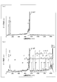
- FIG. 11 is a graph showing the structure analysis result of a phosphorylated peptide (amino acid sequence: YGGMHRQETpVDC, p is a phosphate group), and FIG. 11 (a) shows the structure analysis result when a rare gas is used as the target gas.
- FIG. 11B shows a structural analysis result when an alkali metal gas is used as the target gas.
- the horizontal axis represents the mass-to-charge ratio (m / z)
- the vertical axis represents the peak intensity (arbitrary unit: arbitrary unit, hereinafter abbreviated as “au”).
- an alkali metal gas As the target gas, various structural information that cannot be obtained when a rare gas is used can be acquired, and the accuracy of structural analysis can be significantly improved. That is, as a target gas for performing structural analysis, an alkali metal gas has an advantage over a rare gas, which is also described in Non-Patent Documents 2 and 3.
- FIG. 12 is a schematic diagram for explaining a conventional alkali metal introducing apparatus 100 in the MS / MS method using an alkali metal gas as a target.
- a conventional alkali metal introducing device 100 includes a reservoir 102 into which an alkali metal 112 is introduced, a path 104 through which alkali metal gas flows, a vacuum chamber 106, and a heater 108 that is disposed in the path 104 and that heats the alkali metal gas. And a vacuum pump 110 (not shown). Since these details are disclosed in Non-Patent Document 3, detailed description thereof is omitted here.
- the alkali metal 112 is safely introduced into the reservoir 102, and the alkali metal 112 is heated by the heater 108 to be vaporized as an alkali metal gas. It was necessary to introduce vaporized gas into the vacuum chamber 106. For this purpose, it is first necessary to crush the ampoule containing the alkali metal 112 under a nitrogen atmosphere and under dry conditions. Then, the vacuum state in the vacuum chamber 106 was released, the alkali metal 112 was quickly introduced into the reservoir 102 from the crushed ampule, and then the vacuum chamber 106 was evacuated by the vacuum pump 110.
- the conventional alkali metal introducing device 100 performs the step of crushing the ampoule under a nitrogen atmosphere outside the alkali metal introducing device 100.
- the entire alkali metal introducing device 100 is covered with a transparent plastic bag, and the air therein is replaced with nitrogen gas.
- the end of the ampoule enclosing the alkali metal 112 is crushed to expose the alkali metal to the outside of the ampoule. Then, the alkali metal 112 is introduced into the reservoir 102 for each ampoule.
- the present invention has been made in view of the above-described conventional problems, and an object thereof is to provide an alkali metal introducing device and an alkali metal introducing method excellent in usability.
- an alkali metal introducing device provides An alkali metal introducing device provided for an experiment using an alkali metal gas, A hollow chamber; A vacuum forming section for evacuating the inside of the chamber; Inside the chamber, an alkali exposed in an enclosure, an external exposure part that deforms the enclosure and exposes it to the outside, A container introduction chamber disposed inside the chamber and capable of introducing the enclosed container; A container moving unit that moves the sealed container between an exposed position where the alkali metal is exposed to the outside of the deformed sealed container and an introduction position where the sealed container is introduced into the container introducing chamber; It is characterized by providing.
- an alkali metal introduction method provided for an experiment using an alkali metal gas, A vacuum step for evacuating the chamber in a state in which the enclosure containing the alkali metal is disposed in the hollow chamber; After the vacuum step, the alkali metal is exposed to the outside by deforming the enclosure and exposed outside, After the external exposure step, the alkali metal is exposed to the outside of the deformed enclosure, and the enclosure is disposed in a container introduction chamber that is disposed inside the chamber and into which the enclosure can be introduced. And a container moving step of moving the sealed container between an introduction position where the container is introduced.
- the vacuum forming unit evacuates the inside of the hollow chamber.
- the external exposure part causes the alkali metal enclosed in the enclosure to be exposed outside the chamber by deforming the enclosure.
- the container moving part is disposed inside the chamber, the exposed position exposed to the outside of the sealed container in which the alkali metal is deformed, and the sealed container in the container introduction chamber where the sealed container can be introduced. The enclosure is moved between the introduction positions where the is introduced. Therefore, the alkali metal introducing device (alkali metal introducing method) according to the present invention can introduce the sealed container into the container introducing chamber with the alkali metal exposed to the outside of the sealed container.
- the externally exposed portion deforms the enclosed metal inside the chamber by transforming the enclosed metal into the enclosed container. Expose to the outside. At this time, the inside of the hollow chamber is evacuated by a vacuum forming unit (vacuum forming step), whereby moisture inside the chamber can be discharged to the outside of the chamber. Thereby, the ignition which arises when an alkali metal and the water
- the alkali metal sealed in the sealed container is exposed to the outside by deforming the sealed container by the external exposed portion (external exposure step) inside the chamber. For this reason, the risk that the alkali metal adheres to the operator's hand or the like and burns the operator can be eliminated.
- the alkali metal introduction device (alkali metal introduction method) according to the present invention is used as an alkali such as tandem mass spectrometry.
- the operator can be given the option of submitting to an experiment using metal gas.
- the alkali metal introducing device (alkali metal introducing method) according to the present invention is used for tandem mass spectrometry, it is possible to maximize the structural analysis advantage of the alkali metal gas over the rare gas. .
- the sealed container in which the alkali metal is enclosed is directly introduced into the container introduction chamber. Therefore, when the container introduction chamber is used as a collision chamber in which the selected ions and the target gas collide with each other in tandem mass spectrometry (hereinafter also referred to as “collision cell”), the alkali metal is contained in the collision chamber. It will be introduced directly inside. This means that the path described with reference to FIG. 12 becomes unnecessary.
- the alkali metal is once introduced into the reservoir, and the vaporized alkali metal gas is guided to the collision chamber in the vacuum chamber through the path.
- the alkali metal introducing device (alkali metal introducing method) according to the present invention by adopting the above configuration, the path can be omitted, and the effects of simplification of the device and cost reduction are also achieved. be able to. Furthermore, by omitting the path, it is possible to enjoy the advantages of complicated temperature control and elimination of alkali loss until the alkali metal gas is introduced into the collision chamber.
- the container moving part preferably has a container sealing part that seals the inlet of the container introduction chamber into which the sealed container is introduced.
- the inlet of the container introduction chamber is sealed by the container sealing portion. Therefore, even if some processing is performed in the container introduction chamber after the sealed container is introduced into the container introduction chamber, a situation in which a result of the process leaks outside the container introduction chamber is avoided. A highly safe device is provided to the operator.
- the alkali metal introducing device it is preferable to provide a temperature raising mechanism capable of raising the temperature inside the container introduction chamber.
- an enclosure containing alkali metal is introduced in the container introduction chamber.
- the alkali metal is exposed to the outside of the enclosure by the external exposed portion.
- the alkali metal introducing device can vaporize the alkali metal exposed to the outside of the enclosed container by including a temperature raising mechanism capable of raising the temperature inside the container introducing chamber.
- an alkali metal gas can be used as a target gas, and the accuracy of structural analysis can be significantly improved compared to the use of a rare gas. it can.
- the temperature of the alkali metal gas (adjustment of gas density) is performed using not only the heater disposed in the collision chamber but also the heater disposed in the path. Therefore, even if the alkali metal can be safely introduced into the reservoir, the density of the alkali metal gas cannot be adjusted accurately with high responsiveness. As a result, a large amount of alkali metal is wasted when it takes several hours to reach the target alkali metal gas density, or when the alkali metal gas density suddenly increases due to misadjustment. That happened frequently.
- the alkali metal introducing device according to the present invention eliminates the need for the conventional alkali metal introducing system as described above, and can directly introduce the alkali metal into the container introducing chamber.
- the alkali metal introducing device according to the present invention includes a temperature raising mechanism capable of raising the temperature inside the container introducing chamber.
- the alkali metal introducing device can control the gas pressure of the alkali metal gas in the container introducing chamber only by the temperature raising mechanism, and therefore can control with extremely high responsiveness. As a result, it is possible to avoid a situation where a large amount of alkali metal is wasted by mistake in adjustment.
- the alkali metal introducing device it is preferable to provide a cooling mechanism capable of cooling the inside of the container introduction chamber.
- the alkali metal introducing device includes a cooling mechanism capable of cooling the inside of the container introducing chamber.
- the alkali metal introducing device can quickly cool the alkali metal gas by the cooling mechanism when the alkali metal gas exceeds the target temperature. That is, it is possible to control the gas pressure of the alkali metal gas with higher responsiveness, and as a result, it is possible to suppress wasteful consumption of the alkali metal.
- the temperature raising mechanism is a mechanism for raising the temperature of the container introduction chamber using a heater
- the cooling mechanism is preferably a mechanism that cools the container introduction chamber using liquid nitrogen.
- Temperature control using a heater and liquid nitrogen is a technique used in plants and the like, and high-speed control within a range of ⁇ 0.5 degrees from the target set temperature is possible.
- the gas pressure of the alkali metal gas in the container introduction chamber can be controlled at high speed.
- a heating mechanism that uses a heater and a cooling mechanism that uses liquid nitrogen high-speed control is possible within a range of ⁇ 0.5 degrees from the target set temperature. Can be realized.
- a mode in which the gas amount can be precisely controlled and the alkali metal is consumed in a pulse manner by the switching operation of the “high-speed switch” is realized.
- the alkali metal introducing device according to the present invention has an effect that the consumption of the alkali metal can be optimally controlled by providing the above-described configuration.
- the alkali metal introducing device includes a hollow chamber, a vacuum forming unit for evacuating the inside of the chamber, and an alkali metal sealed in an enclosure inside the chamber.
- An externally exposed part that deforms the enclosure and exposes it to the outside;
- a container introduction chamber disposed inside the chamber and capable of introducing the enclosure; an exposed position where the alkali metal is exposed to the outside of the deformed enclosure; and the enclosure is the container introduction chamber.
- a container moving unit that moves the sealed container between the introduction position and the introduction position.
- the alkali metal introduction method includes a vacuum step of evacuating the chamber in a state where the sealing container enclosing the alkali metal is disposed in the hollow chamber, and the vacuum step. Later, the external exposure step of exposing the alkali metal to the outside by deforming the enclosure, and the exposure position where the alkali metal is exposed to the outside of the transformed enclosure after the external exposure step; And a container moving step of moving the sealed container to and from an introduction position where the sealed container is introduced into a container introduction chamber in which the sealed container can be introduced.
- (E) shows a method of striking the top of the ampoule with a certain object vigorously
- (f) shows a method of scratching and crushing the top of the ampoule with something like a blade.
- the alkali metal introducing device 1 will be described.
- an application example of the alkali metal introducing device 1 will be described with reference to FIG. 2, and then the schematic configuration of the alkali metal introducing device 1 will be described with reference to FIG.
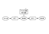
- FIG. 2 is a diagram for explaining a schematic flow of tandem mass spectrometry.
- tandem mass spectrometry generally two mass spectrometers are connected via a collision chamber (hereinafter also referred to as “collision cell”).
- the first mass spectrometer (MS-1) selects an ion having a predetermined mass-to-charge ratio (m / z), and then causes the selected ion to collide with the target gas in the collision cell. Dissociate. Then, the second mass spectrometer (MS-2) mass-analyzes the generated fragment ions and acquires structural information such as amino acid sequences.
- the alkali metal introducing device 1 is used for introducing an alkali metal serving as a target gas into a collision cell. That is, the alkali metal is introduced into the collision cell by the alkali metal introducing device 1, and the alkali metal is vaporized by being heated. The vaporized alkali metal gas is used as a target gas in the collision cell.
- the alkali metal introducing device 1 can be applied to other uses, for example, an experiment of particle collision.
- examples thereof include surface analyzers such as secondary ion mass spectrometers, photomultipliers, and double charge exchange reactions in ITER (International Thermonuclear Experimental Reactor).
- the surface analyzer is, for example, emitting energy particles such as secondary ions and neutral particles from the sample surface by irradiating the sample surface with a beam of primary ions, neutral particles, laser light, and the like. It measures the energy, mass, etc. of particles.
- the alkali metal introducing device 1 is used as a generation source of alkali metal ions that irradiate the sample surface.
- the photomultiplier device can improve the apparent light detection efficiency by multiple reflection of incident light to and from the photoelectric conversion surface with respect to a light detector having low efficiency in a single phenomenon. is there.
- the alkali metal introducing device 1 is used as a supply source of an alkali metal (photoelectric conversion surface material) that is vapor-deposited or coated on a glass surface.
- the double charge exchange reaction in ITER is as follows. That is, a beam neutralization method has been proposed as one method for measuring alpha particles generated by the DT fusion reaction.
- a He 0 beam is incident on a plasma confined by a magnetic field in a fusion reactor, and alpha particles are neutralized by a double charge exchange reaction between He 0 and alpha particles.
- the space and velocity distribution of alpha particles is measured by taking out and measuring.
- the He 0 beam generation of, He - carried out by spontaneous desorption of the beam, He - beam generation of He - double charge exchange with an alkali metal gas beam through the alkali metal gas cell - the He extracted from the ion source Perform by reaction. That is, the alkali metal introducing device 1 is used as a supply source of the alkali metal gas.
- the alkali metal introducing device 1 can be applied to various uses.
- FIG. 1 is a schematic view of an alkali metal introducing device 1.
- the alkali metal introducing device 1 is incorporated in a part of the tandem mass spectrometry and is used when introducing an alkali metal into the collision cell 40.
- the alkali metal introducing device 1 includes a crushing chamber (chamber) 10, an ampoule introduction part (container moving part) 12, an ampoule crushing part (external exposure part) 18, a vacuum chamber (chamber) 20, and a gate valve 30.
- the crushing dedicated chamber 10, the gate valve 30, and the vacuum chamber 20 are arranged in that order from the lower side in the vertical direction.
- the crushing dedicated chamber 10, the gate valve 30, and the vacuum chamber 20 may be realized in a configuration in which the crushing chamber 10, the gate valve 30, and the vacuum chamber 20 are arranged at an oblique angle with respect to the horizontal direction.
- the crushing dedicated chamber 10 has a hollow interior.
- the crushing dedicated chamber 10 is provided with at least an ampoule introduction part 12 and an ampoule crushing part 18.
- the ampoule introduction part 12 has an exposed position where the alkali metal sealed in the ampoule (enclosure container) 16 is exposed to the outside when the ampoule crushing part 18 deforms the ampoule 16 and the ampoule 16 is introduced into the collision cell 40.
- the ampule 16 is moved to and from the introduction position. Therefore, the ampoule introduction unit 12 is movably provided in the direction in which the ampoule 16 is introduced into the collision cell 40 (A direction in the figure) and in the direction in which the ampoule 16 is separated from the collision cell 40 (B direction in the figure). Yes.
- the ampoule introduction unit 12 includes an introduction shaft 13 and an ampoule holder 14.
- the ampoule introduction part 12 needs to be taken out from the crushing dedicated chamber 10 when the ampoule 16 is inserted into the ampoule holder 14 to be described later, and is thus detachable from the crushing dedicated chamber 10.
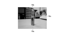
- FIG. 3 is a photograph of the ampoule 16.
- the ampoule 16 may be commercially available, and an alkali metal is sealed inside. As shown in the figure, the ampoule 16 includes a substantially cylindrical ampoule lower part 16a and an ampoule upper part 16b provided on the upper part. The ampoule 16 is easily formed at the boundary 16c between the ampoule lower part 16a and the ampoule upper part 16b when an external force is applied to the ampoule upper part 16b. Thereby, the alkali metal sealed in the ampoule 16 can be exposed to the outside air.
- the kind of alkali metal sealed in the ampoule 16 is not particularly limited, and may be any kind such as lithium, sodium, cesium, or funlansium.
- the introduction shaft 13 is formed in a rod shape, and an ampoule holder 14 is detachably locked to a tip portion thereof.
- a position where the end of the ampoule 16 is crushed that is, a position where the alkali metal sealed in the ampoule 16 is exposed to the outside when the ampoule 16 is deformed by the ampoule crushing part 18 is defined as an exposed position.
- a position where the ampule 16 is introduced into the collision cell 40 is set as an introduction position.
- the introduction shaft 13 formed in a rod shape has a length that is at least the distance from the exposure position to the introduction position.
- the introduction shaft 13 is provided in the crushing chamber 10 in parallel to the direction (AB direction in FIG. 1) to which the crushing chamber 10, the gate valve 30, and the vacuum chamber 20 are connected. However, if the ampoule 16 moves between an exposure position where the alkali metal sealed in the ampoule 16 is exposed to the outside of the ampoule 16 and an introduction position where the ampoule 16 is introduced into the collision cell 40, the introduction shaft 13 is used. (And the ampoule introduction unit 12) may be realized in any shape and configuration.
- the ampoule holder 14 holds an ampoule 16 filled with an alkali metal, and is provided at the tip of the introduction shaft 13.
- the method in which the ampule holder 14 holds the ampule 16 is not particularly limited.
- the ampule holder 14 is engaged with the collision cell 40 while holding the ampule 16.
- the collision cell 40 is heated to vaporize the alkali metal sealed in the ampoule 16.
- the ampoule holder 14 and the collision cell 40 are required to be sufficiently sealed at the engaging portion to ensure the airtightness inside the collision cell 40.
- the engaging portion of the ampoule holder 14 and the collision cell 40 is formed, for example, as a male screw for the ampoule holder 14 and a female screw for the collision cell 40.
- the ampule holder 14 is screwed into the collision cell 40, and when the ampule holder 14 and the collision cell 40 are engaged with each other, the engaging portion is sufficiently engaged. Can create a situation.
- the ampoule introduction unit 12 introduces the ampoule 16 into the collision cell 40. Therefore, by moving the ampoule introduction part 12 in the A direction, the ampoule holder 14 is engaged (screwed) with an opening (not shown) formed in the collision cell 40. Therefore, the opening of the collision cell 40 is positioned so as to be positioned on the axis of the introduction shaft 13.
- the position may be shifted due to vibration of the device.
- the position adjusting device 70 provided inside or outside the alkali metal introducing device 1 adjusts the position of the collision cell 40. Thereby, the positional deviation is adjusted.
- a position adjusting device since a known position adjusting device can be used, detailed description thereof is omitted here.
- the ampoule crushing part 18 is for deforming the ampoule 16 and exposing the alkali metal enclosed in the ampoule 16 to the outside of the ampoule 16 inside the crushing chamber 10.
- the ampoule 16 is crushed in a state where the ampoule 16 is disposed inside. Thereby, the alkali metal sealed in the ampule 16 is exposed to the outside of the ampule 16 by deforming the ampule 16.
- the ampoule crushing portion 18 is realized by a configuration formed integrally with the crushing dedicated chamber 10 or a configuration removable from the crushing dedicated chamber 10.
- FIG. 4A shows a method of hooking a Y-shaped wedge on the ampoule upper portion 16b and rotating the wedge.
- (B) shows a method of piercing (penetrating) the ampoule upper portion 16b with a sharp object.
- (C) of the figure shows a method of fastening the ampoule upper part 16b with a screw or the like.
- FIG. 4D shows a method of crushing the ampoule upper portion 16b by applying pressure from above and from the left and right.
- (E) of FIG. 4 shows a method of plunging the ampoule upper portion 16b with some object.
- (F) of the figure shows a method of scratching and crushing the upper part 16b of the ampoule with something like a blade.
- the ampoule crushing unit 18 can be realized by various methods, and the alkali metal introducing device 1 can adopt any method. It should be noted that the ampoule crushing portion 18 can also be realized by a method other than that disclosed in FIG.
- the vacuum chamber 20 has a hollow interior.
- a collision cell 40 is disposed inside the vacuum chamber 20.
- the gate valve 30 has a lower surface connected to the crushing dedicated chamber 10 and an upper surface connected to the vacuum chamber 20. That is, the crushing chamber 10 and the vacuum chamber 20 are connected via the gate valve 30. When the gate valve 30 is “open”, the crushing dedicated chamber 10 and the vacuum chamber 20 are communicated with each other, and “closed”, thereby blocking the communication.
- the collision cell 40 is disposed inside the vacuum chamber 20.
- the collision cell 40 has an opening (not shown).
- the opening and the ampoule holder 14 are engaged (screwed). Positioned to do so. That is, the opening of the collision cell 40 is positioned so as to be positioned on the axis of the introduction shaft 13.
- the collision cell 40 Since the purpose of the collision cell 40 is the same as that of a so-called general collision cell, a detailed description thereof is omitted here.
- the temperature control mechanism 50 includes a liquid nitrogen container 52, a cooling line (cooling mechanism) 54, and a heating line (temperature raising mechanism) 56.
- the liquid nitrogen container 52 stores liquid nitrogen therein and is sufficiently warmed so that the temperature of the liquid nitrogen does not increase.
- the cooling line 54 is a piping line provided between the liquid nitrogen container 52 and the collision cell 40.
- the liquid nitrogen is passed from the liquid nitrogen container 52 to the collision cell 40 by a pump (not shown), the internal temperature of the collision cell 40 is cooled, and then returned to the liquid nitrogen container 52.
- the heating line 56 is an electric cable for a heater provided in the collision cell 40, and the heater is used to raise the internal temperature of the collision cell 40.
- Temperature control using a heater and liquid nitrogen is a technique used in a plant or the like, although there is no example applied in this field, and the internal temperature of the collision cell 40 is set to ⁇ 0.5 degrees of the target temperature. Temperature control is possible within the range. In addition, since the temperature control is a well-known technique, the detail is abbreviate
- cooling line 54 may be realized with a configuration using, for example, a liquid rim or dry ice, instead of liquid nitrogen.
- the vacuum pump 60a is for evacuating the inside of the crushing dedicated chamber 10, and the vacuum pump 60b is for evacuating the inside of the vacuum chamber 20.
- the vacuum pump 60a and the vacuum pump 60b may be realized with a configuration in which one vacuum pump is shared.
- a dedicated pipe, a valve, a vacuum buffer tank, etc. are used for evacuating the hollow container.
- a dedicated pipe, a valve, a vacuum buffer tank, etc. are used for evacuating the hollow container.
- a detailed description thereof is omitted.
- the position adjusting device 70 is provided inside or outside the alkali metal introducing device 1, and when the collision cell 40 arranged inside the vacuum chamber 20 is displaced due to vibration or the like, the position adjusting device 70 is adjusted to the original position. Is to do.
- the schematic configuration of the alkali metal introducing device 1 has been described above.
- the material used may be a material other than stainless steel.
- the alkali metal introducing device 1 includes the crushing dedicated chamber 10, the vacuum chamber 20, and the gate valve 30, and the crushing dedicated chamber 10 and the vacuum chamber 20 are connected via the gate valve 30.
- the gate valve 30 explained as a thing.
- the alkali metal introducing device 1 may be realized by a configuration in which the gate valve 30 is not provided, that is, a configuration in which the crushing dedicated chamber 10 and the vacuum chamber 20 are integrated.
- FIG. 5 is a view for explaining a method of engaging the ampoule holder 14 with the collision cell 40.
- the description is abbreviate
- the ampule holder 14 is engaged (tightly fitted) with the collision cell 40 while holding the ampule 16.
- the collision cell 40 is heated to vaporize the alkali metal sealed in the ampoule 16. Therefore, the ampule holder 14 and the collision cell 40 need to be sufficiently engaged with each other to ensure the airtightness of the collision cell 40.
- the engaging portion of the ampoule holder 14 and the collision cell 40 is, for example, a male screw for the ampoule holder 14 and a female screw for the collision cell 40.
- FIG. 5 shows such a state.
- the ampoule holder 14 and the collision cell 40 are screwed together, and the ampoule holder 14 and the collision cell 40 can create a state in which their engaging portions are sufficiently engaged. Therefore, when the temperature control mechanism 50 adjusts the temperature inside the collision cell 40, the outside air flows into the collision cell 40 or the air inside the collision cell 40 flows out, making it difficult to adjust the temperature. The situation of becoming is prevented.
- FIG. 6 is a schematic diagram for explaining the stoppers 80 a and 80 b and the protective cap 82.
- the description is abbreviate
- the ampule 16 is crushed by the ampule crushing portion 18 in the crushing dedicated chamber 10.
- the crushing chamber 10 is evacuated by the vacuum pump 60a. Therefore, the ampoule introduction part 12 and the ampoule crushing part 18 may be sucked unless measures are taken against the vacuum, causing damage or the like in the worst case.
- stoppers 80a and 80b at or near the contact portion between the ampoule introduction part 12 and the ampoule crushing part 18 and the crushing dedicated chamber 10.
- the stoppers 80a and 80b may be realized by any known technique.
- FIG. 7 is a view for explaining an embodiment of the stoppers 80a and 80b.
- the introduction shaft 13 is provided with a stopper 80a
- the ampule crushing portion 18 is provided with a stopper 80b.
- handle types are used as the stoppers 80a and 80b. By turning the handle, the shaft portion of the introduction shaft 13 and the ampoule crushing portion 18 is fixed so as not to operate.
- the protective cap 80 will be described with reference to FIG.
- the ampule 16 is crushed by the ampule crushing portion 18 in the crushing dedicated chamber 10.
- a protective cap 82 for covering the O-ring is provided at a position covering the top of the O-ring.
- Such a protective cap 82 may be realized by any known technique.
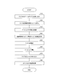
- FIG. 8 is a flowchart for explaining the alkali metal introduction method.
- the ampule 16 is inserted into the ampule holder 14.
- the ampule introduction part 12 is in a state of being completely pulled out from the crushing dedicated chamber 10, and the ampule 16 in which a desired alkali metal is sealed is inserted into the ampule holder 14 by the operator.
- the ampoule introduction part 12 holding the ampoule 16 is inserted into the crushing dedicated chamber 10.
- the operator looks through the transparent window provided in the crushing chamber 10 and inserts the ampoule 16 to a predetermined position (exposed position) to be crushed. .
- a mark is placed on the introduction shaft 13, and the ampule 16 is inserted into the crushing dedicated chamber 10 until the ampoule 16 is inserted to the position of the mark. It can also be positioned at the exposure position.
- the gate valve 30 is set to “closed”. Thereby, the communication between the crushing dedicated chamber 10 and the vacuum chamber 20 is blocked. Note that, when the crushing dedicated chamber 10 and the vacuum chamber 20 are realized in an integrated configuration, the gate valve 30 does not exist, and in this case, this step is omitted.
- the crushing dedicated chamber 10 is evacuated by the vacuum pump 60a and the vacuum chamber 20 is evacuated by the vacuum pump 60b. Thereby, the water
- the ampoule crushing unit 18 crushes the ampoule 16 positioned at the exposed position.
- the ampoule 16 is easily broken at the boundary 16c between the ampoule lower part 16a and the ampoule upper part 16b by applying an external force to the ampoule upper part 16b. Therefore, the ampoule crushing part 18 applies an external force to the ampoule upper part 16b, whereby the ampoule lower part 16a and the ampoule upper part 16b are folded at the boundary part 16c. To expose.
- step S40 the vacuum chamber 20 is also kept in a vacuum, and there is no moisture in the vacuum chamber 20. Therefore, even if the gate valve 30 is “open”, a situation in which the alkali metal exposed to the outside of the ampoule 16 reacts with moisture in the vacuum chamber 20 to ignite is avoided.
- the ampule 16 is introduced into the collision cell 40 in S70. This is because the ampule 16 is introduced into the collision cell 40 by pushing the ampule introduction part 12 in the direction A of FIG.
- the internal temperature of the collision cell 40 is controlled to the target temperature by the temperature control mechanism 50.
- control temperature differs depending on the type of alkali metal sealed in the ampoule 16, the target gas density of the alkali metal gas vaporized in the collision cell 40, and the like.
- a temperature control technique performed by combining liquid nitrogen and a heater is a technique that is used in a plant or the like, although it is not used in this field, and the internal temperature of the collision cell 40 is set to ⁇ 0 of the target temperature. It is possible to control within a range of 5 degrees.
- the alkali metal introduction method according to the present invention has been described above.
- each step of S20 to S80 may be performed manually, or all of them may be subjected to automation control.
- the alkali metal introduction system and the reaction chamber should be heated (Bake Out) in order to remove water molecules adhering to the alkali metal introduction system and the reaction chamber of the two mass spectrometers. Is preferred. This operation can reduce background noise due to impurities inside the mass spectrometer. Furthermore, when alkali metal gas is introduced into the reaction chamber, it prevents reaction with water molecules and unnecessary consumption of alkali metal. Because it can.
- the alkali metal introducing device 1 is used for an experiment using an alkali metal gas, and includes a crushing chamber 10 and a vacuum chamber 20, and a vacuum pump 60 a that evacuates the crushing chamber 10 and the vacuum chamber 20. 60b, an ampoule crushing portion 18 for deforming the ampule 16 and exposing the alkali metal enclosed in the ampule 16 inside the crushing dedicated chamber 10 to the outside, and the inside of the vacuum chamber 20, the ampule 16 A collision cell 40 in which the ampule 16 can be introduced, and an ampule that moves the ampule 16 between an exposure position where the alkali metal is exposed to the outside of the deformed ampule 16 and an introduction position where the ampule 16 is introduced into the collision cell 40. And an introduction unit 12.
- the alkali metal introduction method according to the present invention is used in an experiment using an alkali metal gas, and the crushing chamber 10 is evacuated in a state where the ampoule 16 enclosing the alkali metal is disposed in the crushing chamber 10.
- a container moving step for moving the ampule 16 between the introduction position where the ampule 16 is introduced into the collision cell 40 which is disposed inside the chamber and into which the ampule 16 can be introduced. It is said.
- the vacuum pumps 60a and 60b evacuate the inside of the crushing dedicated chamber 10 and the vacuum chamber 20.
- the ampoule crushing unit 18 (external exposure step) causes the alkali metal enclosed in the ampoule 16 inside the crushing dedicated chamber 10 to be exposed to the outside by deforming the ampoule 16.
- the ampoule introduction part 12 (container moving step) is provided in an exposure position exposed outside the ampoule 16 in which the alkali metal is deformed, and in the collision cell 40 which is disposed inside the vacuum chamber 20 and into which the ampoule 16 can be introduced.
- the ampule 16 is moved between the introduction position where the ampoule 16 is introduced. Therefore, the alkali metal introduction device 1 can introduce the ampule 16 into the collision cell 40 in a state where the alkali metal is exposed to the outside of the ampule 16.
- the ampule crushing unit 18 deforms the ampule 16 to expose the alkali metal enclosed in the ampule 16 inside the crushing dedicated chamber 10.
- the inside of the crushing chamber 10 is evacuated by the vacuum pump 60a (vacuum forming step), so that the water inside the crushing chamber 10 can be discharged to the outside of the chamber. Thereby, the ignition which arises when an alkali metal and the water
- the alkali metal sealed in the ampoule 16 is exposed to the outside when the ampoule 16 is deformed by the ampoule crushing portion 18 (external exposure step) inside the crushing dedicated chamber 10. For this reason, the risk that the alkali metal adheres to the operator's hand or the like and burns the operator can be eliminated.
- the alkali metal introducing device 1 is subjected to an experiment using an alkali metal gas such as tandem mass spectrometry. Options can be given to workers.
- an alkali metal gas such as tandem mass spectrometry.
- the alkali metal introducing device 1 the ampule 16 enclosing the alkali metal is directly introduced into the collision cell 40. For this reason, when the collision cell 40 is used as a collision chamber in which the selected ions and the target gas collide in tandem mass spectrometry, the alkali metal is directly introduced into the collision chamber. This means that the path 104 described with reference to FIG. 12 becomes unnecessary.
- alkali metal is once introduced into the reservoir 102, and the alkali metal gas vaporized there is guided to the collision chamber in the vacuum chamber 106 via the path 104.
- the path can be omitted, and the effects of simplification of the device and cost reduction can be achieved.
- the path 104 it is possible to enjoy the advantages of complicated temperature control and elimination of alkali loss until the alkali metal gas is introduced into the collision chamber.
- the ampoule introducing unit 12 has an ampoule holder 14 for sealing the introduction port of the collision cell 40 into which the ampoule 16 is introduced.
- the inlet of the collision cell 40 is sealed by the ampoule holder 14. Therefore, even if some processing is performed in the collision cell 40 after the ampoule 16 is introduced into the collision cell 40, a situation in which the result of the processing leaks to the outside of the collision cell 40 can be avoided, and further safety can be achieved. High equipment is provided to the operator.
- the alkali metal introducing device 1 is configured to include a heating line 56 capable of raising the temperature inside the collision cell 40.
- An ampoule 16 in which an alkali metal is sealed is introduced into the collision cell 40.
- the alkali metal is exposed to the outside of the ampoule 16 by the ampoule crushing portion 18.
- the alkali metal introducing device 1 can vaporize the alkali metal exposed to the outside of the ampoule 16 by providing the heating line 56 capable of raising the temperature inside the collision cell 40.
- an alkali metal gas can be used as a target gas, and the accuracy of structural analysis can be significantly improved compared to the use of a rare gas. it can.
- the temperature of the alkali metal gas (adjustment of gas density) is also adjusted using the heater 108 provided in the path 104. I was going. Therefore, even if the alkali metal can be safely introduced into the reservoir 102, the density of the alkali metal gas cannot be adjusted accurately with high responsiveness. As a result, a large amount of alkali metal is wasted when it takes several hours to reach the target alkali metal gas density, or when the alkali metal gas density suddenly increases due to misadjustment. It happened frequently.
- the alkali metal introducing device 1 does not require the path 104 that is necessary for the conventional alkali metal introducing device 100 and can directly introduce the alkali metal into the collision cell 40.
- the alkali metal introducing device 1 includes a heating line 56 that can raise the temperature inside the collision cell 40.
- the alkali metal introducing device 1 can control the gas pressure of the alkali metal gas in the collision cell 40 only by the heating line 56, and therefore can control with extremely high responsiveness. As a result, it is possible to avoid a situation where a large amount of alkali metal is wasted due to erroneous adjustment.
- the alkali metal introducing device 1 is configured to include a cooling line 54 that can cool the inside of the collision cell 40.
- the alkali metal introducing device 1 includes a cooling line 54 capable of cooling the inside of the collision cell 40.
- the alkali metal introducing device 1 can quickly cool the alkali metal gas by the cooling line 54 when the alkali metal gas exceeds the target temperature. That is, it is possible to control the gas pressure of the alkali metal gas with higher responsiveness, and as a result, it is possible to suppress wasteful consumption of the alkali metal.
- the heating line 56 is a mechanism that raises the temperature of the collision cell 40 using a heater
- the cooling line 54 is a mechanism that cools the collision cell 40 using liquid nitrogen. is there.
- Temperature control using a heater and liquid nitrogen is a technique used in plants and the like, and high-speed control within a range of ⁇ 0.5 degrees from the target set temperature is possible.
- the gas pressure of the alkali metal gas in the collision cell 40 can be controlled at high speed.
- the heating line 56 using a heater and the cooling line 54 using liquid nitrogen high-speed control within a range of ⁇ 0.5 degrees from the target set temperature is possible.
- Switch can be realized. And, by the switching operation of the “high-speed switch”, it is possible to control the gas amount precisely and to consume the alkali metal in a pulsed manner, that is, it is possible to optimally control the consumption amount of the alkali metal. . ⁇ Example ⁇
- examples of the alkali metal introducing device 1 and effects obtained will be described.
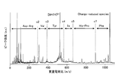
- FIG. 9 is a graph showing a structural analysis result of angiotensin II when an alkali metal gas is used as a target gas.
- the horizontal axis represents the mass-to-charge ratio (m / z), and the vertical axis represents the peak intensity (au).
- the alkali metal used was cesium.
- performance evaluation by the alkali metal introduction apparatus 1 was performed using a standard biological sample called angiotensin II (amino acid sequence: Asp-Arg-Val-Tyr-Ile-His-Pro-Phe).
- angiotensin II amino acid sequence: Asp-Arg-Val-Tyr-Ile-His-Pro-Phe.
- the operation of the alkali metal introducing device 1 is based on the method described with reference to FIG.
- the target temperature in the collision cell 40 was set to 130 degrees, and temperature control was performed using the heating line 56 and the cooling line 54. As a result, the target temperature (130 degrees) was reached in just a few minutes, and the temperature stability was within ⁇ 0.5 degrees.
- FIG. 9 is a graph showing the structure analysis result of Angiotensin II at that time, and is a graph showing the result of trying the structure analysis by colliding ions of Angiotensin II with an alkali metal gas (target gas).
- FIG. 10 is a graph showing changes in the intensity of precursor ions when the heater is turned on and off.
- the horizontal axis represents the flight time (us), and the vertical axis represents the peak intensity (au).
- the heater when the heater is turned off, the peak intensity of the alkali metal gas rapidly decreases. Moreover, the temperature control in the collision cell 40 is performed quickly. Therefore, waste of alkali metal consumption can be minimized by turning the heater ON / OFF. Although not described in this embodiment, the same effect can be obtained not only by turning on / off the heater but also by turning on / off the liquid nitrogen line.
- the present embodiment performs temperature control using a heater and liquid nitrogen. This technique is used in a plant or the like and is operated at a high speed within a range of ⁇ 0.5 degrees from a target set temperature. Control is possible.
- the gas pressure of the alkali metal gas in the collision cell 40 can be controlled at high speed by the ON / OFF control of the cooling line 54 and the heating line 56, so to speak, a “high-speed switch by heat” can be realized. .
- a mode in which the gas amount can be precisely controlled and the alkali metal is consumed in a pulse manner by the switching operation of the “high-speed switch” is realized.
- waste of alkali metal consumption can be minimized.
- the alkali metal enclosed in the ampule 16 may spill into the crushing dedicated chamber 10.
- the crushing chamber 10 is corroded by an alkali metal, or a hydroxide is deposited inside the crushing chamber 10 to accumulate dirt.
- the ampoule 16 is composed of a cartridge having a detachable lid, the same function as that of the ampoule crushing unit 18, that is, a function of exposing the alkali metal sealed in the cartridge to the outside of the cartridge.
- the lid can be opened by a lid opening / closing section (externally exposed section) having the above, whereby the problem of alkali metal spilling into the crushing dedicated chamber 10 is solved.
- the alkali metal introducing device 1 can be suitably applied.
- the alkali metal introducing device 1 can be used even if the operator is not skilled. Can be used safely. This contrasts with the conventional alkali metal introduction apparatus 100 in which the worker is limited to only skilled workers due to the difficulty in handling alkali metals, and the use of alkali metal gas as a target gas is widespread. This is a great help.
- the alkali metal introducing device 1 has much improved usability compared to the conventional alkali metal introducing device 100.
- the present invention relates to an alkali metal introduction device and an alkali metal introduction method excellent in usability, and can be suitably used particularly for a mass spectrometer for analyzing a biopolymer such as a protein or a peptide.
Landscapes
- Chemical & Material Sciences (AREA)
- Analytical Chemistry (AREA)
- Other Investigation Or Analysis Of Materials By Electrical Means (AREA)
- Electron Tubes For Measurement (AREA)
Abstract
アルカリ金属導入装置(1)は、アルカリ金属ガスを使用する実験に供されるものであり、破砕専用チャンバー(10)および真空チャンバー(20)と、破砕専用チャンバー(10)および真空チャンバー(20)の内部を真空引きする真空ポンプ(60a)・(60b)と、破砕専用チャンバー(10)の内部において、アンプル(16)に封入されたアルカリ金属を、そのアンプル(16)を変形させて外部に露出させるアンプル破砕部(18)と、真空チャンバー(20)の内部に配設され、アンプル(16)の導入が可能なコリジョンセル(40)と、アンプル(16)に封入されたアルカリ金属が、変形されたアンプル(16)の外部に露出する露出位置と、アンプル(16)がコリジョンセル(40)に導入される導入位置との間でアンプル(16)を移動させるアンプル導入部(12)と、を備える。それゆえ、ユーザビリティーに優れたアルカリ金属導入装置を提供することができる。
Description
本発明は、ユーザビリティーに優れたアルカリ金属導入装置、及びアルカリ金属導入方法に関する。
近年、マトリックス支援レーザー脱離イオン化法(MALDI法)やエレクトロスプレーイオン化法(ESI法)などのソフトイオン化法の開発が進展しており、タンパク質やペプチドなどの生体高分子の分析に質量分析が用いられるようになってきた。
現在、これらの生体高分子の構造解析には、タンデム質量分析法(MS/MS法:mass spectrometer/mass spectrometer法)が広く利用されている。タンデム質量分析法では、一般的に2台の質量分析装置を接続し、1台目の質量分析装置は、所定の質量電荷比(m/z)を有するイオンを選択し、次に、衝突室内で、その選択されたイオンをターゲットガスと衝突させて解離(CID:Collision-induced dissociation)させる。そして、2台目の質量分析装置は、生成したフラグメントイオンを質量分析し、アミノ酸配列などの構造情報を取得する。
ここで、ターゲットガスは、一般的に希ガスが用いられる。なお、数少ないケースであるものの、ターゲットガスとしてアルカリ金属ガスが使用されることもあり、その例が、例えば非特許文献1~3に開示されている。
大阪府立大学大学院理学系研究科物質科学専攻物質設計分野 2005年度修士論文 北口明宏氏「励起中性脂肪酸エステルの解離および多価イオンの電子移動解離」
長尾博文, et al., J. Mass Spectrom. Soc. Jpn., 57 (2009) 123-132.
S. Hayakawa, et al., Rapid Commun. Mass Spectrom., 22 (2008) 567-572.
しかしながら、ターゲットガスとしてアルカリ金属ガスを用いた場合、図11を参照して説明する以下の問題が生じる。
図11は、リン酸化ペプチド(アミノ酸配列:YGGMHRQETpVDC,p はリン酸基)の構造解析結果を示すグラフであり、図11(a)は、ターゲットガスとして希ガスを用いたときの構造解析結果を、図11(b)は、ターゲットガスとしてアルカリ金属ガスを用いたときの構造解析結果を示す。なお、両図ともに、横軸は質量電荷比(m/z)を、縦軸はピーク強度(arbitrary unit:任意単位、以下「a.u.」と略す。)を示す。
図示するとおり、図11(a)では、おもに750(m/z)のみにおいて図中[M+2H]2+で示される、解離せずに残ったプリカーサーイオンのピークが観測される。これに対して、図11(b)では、750(m/z)以外の質量電荷比においても多数のフラグメントイオンのピークが観測される。つまり、アルカリ金属ガスをターゲットガスとすることにより、数多くのフラグメントイオンのピークを生成させることができる。そして、これらのフラグメントイオンは、互いのピーク間隔から、アミノ酸配列や修飾基の種類、位置を特定させる重要な情報源となるものである。従って、ターゲットガスとしてアルカリ金属ガスを使用することにより、希ガスを使用したときには得ることができない種々の構造情報を取得でき、構造解析の精度を格段に向上させることができる。すなわち、構造解析を行う際のターゲットガスとして、アルカリ金属ガスは希ガスに対して優位性を有し、このことは、非特許文献2、3にも記載されている。
このように、構造解析を行ううえで、アルカリ金属ガスは希ガスに対して優位性を有する。それにも係らず、ターゲットガスとして一般的に希ガスが用いられるには理由がある。そのことを図12により説明する。図12は、ターゲットとしてアルカリ金属ガスを用いたMS/MS法における、従来のアルカリ金属導入装置100を説明するための概略図である。
従来のアルカリ金属導入装置100は、アルカリ金属112が導入されるリザーバー102と、アルカリ金属ガスが流れるパス104と、真空チャンバー106と、パス104に配設された、アルカリ金属ガスを加熱するヒーター108と、図示しない真空ポンプ110と、を備える。なお、これらの詳細は非特許文献3に開示されているため、ここでの詳細説明は省略する。
アルカリ金属ガスを真空容器内で扱うアルカリ金属導入装置100では、アルカリ金属112を安全にリザーバー102内に導入し、そのアルカリ金属112をヒーター108で加熱することにより、アルカリ金属ガスとして気化させ、その気化ガスを真空チャンバー106に導入する必要があった。そのためには、まず、アルカリ金属112を封入したアンプルを窒素雰囲気下および乾燥条件下で破砕する必要がある。そして、真空チャンバー106における真空状態を解除して、その破砕したアンプルからアルカリ金属112を素早くリザーバー102内に導入し、そのうえで、真空チャンバー106を真空ポンプ110により真空引きするという手順を取っていた。
しかしながら、従来のアルカリ金属導入装置100は、窒素雰囲気下でアンプルを破砕する工程をアルカリ金属導入装置100の系外で行っていた。
より具体的に説明すると、まずアルカリ金属導入装置100全体を透明ビニール袋で覆い、その中の空気を窒素ガスで置換する。次に、アルカリ金属112を封入したアンプルの端部を破砕し、アルカリ金属をアンプルの外部に露出させる。そして、アンプルごと、アルカリ金属112をリザーバー102に導入する。
このため、窒素雰囲気下で破砕したアンプルをリザーバー102内に導入するときに、アルカリ金属112が空気中に残存する水分と反応してしまい、アルカリ金属112が発火するなどの危険が生じていた。また、発火以外にも、アルカリ金属112が作業者の手に付着した場合には火傷を引き起こす、アルカリ金属112が床にこぼれた場合には、アルカリ金属であるがゆえに水をかけて清掃することができない、といった数多くの問題があった。
このように、アルカリ金属の取り扱いの困難性ゆえに、ターゲットガスとしてアルカリ金属ガスの優位性が認められつつも、希ガスが用いられている。
本願発明は、前記従来の問題点に鑑みなされたものであって、その目的は、ユーザビリティーに優れたアルカリ金属導入装置、及びアルカリ金属導入方法を提供することにある。
本発明に係るアルカリ金属導入装置は、上記の課題を解決するために、
アルカリ金属ガスを使用する実験に供されるアルカリ金属導入装置であって、
中空のチャンバーと、
上記チャンバーの内部を真空引きする真空形成部と、
上記チャンバーの内部において、封入容器に封入されたアルカリ金属を、その封入容器を変形させて外部に露出させる外部露出部と、
上記チャンバーの内部に配設され、上記封入容器の導入が可能な容器導入室と、
上記アルカリ金属が、変形された上記封入容器の外部に露出する露出位置と、上記封入容器が上記容器導入室に導入される導入位置との間で上記封入容器を移動させる容器移動部と、を備えることを特徴としている。
アルカリ金属ガスを使用する実験に供されるアルカリ金属導入装置であって、
中空のチャンバーと、
上記チャンバーの内部を真空引きする真空形成部と、
上記チャンバーの内部において、封入容器に封入されたアルカリ金属を、その封入容器を変形させて外部に露出させる外部露出部と、
上記チャンバーの内部に配設され、上記封入容器の導入が可能な容器導入室と、
上記アルカリ金属が、変形された上記封入容器の外部に露出する露出位置と、上記封入容器が上記容器導入室に導入される導入位置との間で上記封入容器を移動させる容器移動部と、を備えることを特徴としている。
また、本発明に係るアルカリ金属導入方法は、上記の課題を解決するために、
アルカリ金属ガスを使用する実験に供されるアルカリ金属導入方法であって、
アルカリ金属を封入した封入容器が中空のチャンバーに配設された状態で、そのチャンバーを真空引きする真空ステップと、
上記真空ステップの後に、上記アルカリ金属を、その封入容器を変形させて外部に露出させる外部露出ステップと、
上記外部露出ステップの後に、上記アルカリ金属が、変形された上記封入容器の外部に露出する露出位置と、上記チャンバーの内部に配設され、上記封入容器を導入可能な容器導入室に上記封入容器が導入される導入位置との間で上記封入容器を移動させる容器移動ステップと、を含むことを特徴としている。
アルカリ金属ガスを使用する実験に供されるアルカリ金属導入方法であって、
アルカリ金属を封入した封入容器が中空のチャンバーに配設された状態で、そのチャンバーを真空引きする真空ステップと、
上記真空ステップの後に、上記アルカリ金属を、その封入容器を変形させて外部に露出させる外部露出ステップと、
上記外部露出ステップの後に、上記アルカリ金属が、変形された上記封入容器の外部に露出する露出位置と、上記チャンバーの内部に配設され、上記封入容器を導入可能な容器導入室に上記封入容器が導入される導入位置との間で上記封入容器を移動させる容器移動ステップと、を含むことを特徴としている。
従来のアルカリ金属ガスを使用する実験において、例えばタンデム質量分析法では、ターゲットガスとしてアルカリ金属ガスを使用する方が、希ガスを使用するよりも構造解析の精度を格段に向上させることが知られている。それにも係らず、ターゲットガスとしては希ガスの方が一般的である。これは、アルカリ金属の取り扱いの困難性に起因するものであり、アルカリ金属と空気中の水分との反応によって生じる発火や手に付着したときの火傷などが、ターゲットガスとしてのアルカリ金属の使用または普及を阻害してきた。
この点、本発明に係るアルカリ金属導入装置(アルカリ金属導入方法)では、真空形成部(真空形成ステップ)が、中空のチャンバーの内部を真空引きする。そして、外部露出部(外部露出ステップ)が、チャンバーの内部において、封入容器に封入されたアルカリ金属を、その封入容器を変形させて外部に露出させる。さらに、容器移動部(容器移動ステップ)が、アルカリ金属が変形された上記封入容器の外部に露出する露出位置と、チャンバーの内部に配設され、封入容器を導入可能な容器導入室に封入容器が導入される導入位置との間で封入容器を移動させる。従って、本発明に係るアルカリ金属導入装置(アルカリ金属導入方法)は、アルカリ金属を封入容器の外部に露出させた状態で、その封入容器を容器導入室に導入することができる。
つまり、本発明に係るアルカリ金属導入装置(アルカリ金属導入方法)では、外部露出部(外部露出ステップ)が、チャンバーの内部において、封入容器に封入されたアルカリ金属を、その封入容器を変形させて外部に露出させる。このとき、中空のチャンバーの内部を真空形成部(真空形成ステップ)によって真空引きしておくことにより、チャンバー内部の水分をチャンバーの外部に排出しておくことができる。これにより、アルカリ金属とチャンバー内部の水分とが反応することによって生ずる発火を回避することができる。
さらに、封入容器に封入されたアルカリ金属は、チャンバーの内部において、外部露出部(外部露出ステップ)によってその封入容器が変形されることにより外部に露出される。このため、作業者の手などにアルカリ金属が付着し、その作業者に火傷を負わすリスクも排除することができる。
従って、取り扱いの困難性ゆえに敬遠されてきたアルカリ金属を安全に容器導入室に導入することができるため、本発明に係るアルカリ金属導入装置(アルカリ金属導入方法)を、タンデム質量分析法等のアルカリ金属ガスを使用する実験に供するという選択肢を作業者に与えることができる。そして、本発明に係るアルカリ金属導入装置(アルカリ金属導入方法)をタンデム質量分析法に供した場合には、希ガスに対するアルカリ金属ガスの構造解析上の優位性を最大限に享受することができる。
加えて、本発明に係るアルカリ金属導入装置(アルカリ金属導入方法)では、アルカリ金属を封入した封入容器が容器導入室に直接導入される。そのため、容器導入室を、タンデム質量分析法における選択イオンとターゲットガスとが衝突する衝突室(以下、「コリジョンセル」と称する場合もある。)として使用した場合には、アルカリ金属は衝突室の内部に直接導入されることになる。このことは、図12を参照して説明したパスが不要となることを意味する。
つまり、従来用いられているアルカリ金属導入系では、アルカリ金属を一旦リザーバーに導入し、そこで気化されたアルカリ金属ガスが、パスを介して真空チャンバー内の衝突室に導かれていた。これに対して、本発明に係るアルカリ金属導入装置(アルカリ金属導入方法)では、上記構成とすることにより、そのパスを省略することができ、装置の簡略化、コストダウンという効果を併せて奏することができる。さらに、パスを省略することにより、複雑な温度制御や、アルカリ金属ガスを衝突室に導くまでの間のアルカリのロスを無くすという利点も享受することができる。
さらに、本発明に係るアルカリ金属導入装置では、
上記容器移動部は、上記封入容器が導入される上記容器導入室の導入口を密閉する容器密閉部を有することが好ましい。
上記容器移動部は、上記封入容器が導入される上記容器導入室の導入口を密閉する容器密閉部を有することが好ましい。
上記構成とすることにより、本発明に係るアルカリ金属導入装置では、容器導入室の導入口は、上記容器密閉部によって密閉される。従って、上記容器導入室に上記封入容器が導入された後に、当該容器導入室で何らかの処理が行われたとしても、その処理による結果物が容器導入室の外部に漏洩する事態は避けられ、さらに安全性の高い装置が作業者に提供される。
さらに、本発明に係るアルカリ金属導入装置では、
上記容器導入室の内部を昇温することが可能な昇温機構を備えることが好ましい。
上記容器導入室の内部を昇温することが可能な昇温機構を備えることが好ましい。
容器導入室には、アルカリ金属を封入した封入容器が導入される。そのアルカリ金属は、上記外部露出部によって封入容器の外部に露出している。
従って、本発明に係るアルカリ金属導入装置は、上記容器導入室の内部を昇温することが可能な昇温機構を備えることにより、封入容器の外部に露出したアルカリ金属を気化させることができる。
それゆえ、アルカリ金属ガスを使用する実験において、例えばタンデム質量分析法では、ターゲットガスとしてアルカリ金属ガスを使用することができ、希ガスを使用するよりも構造解析の精度を格段に向上させることができる。
さらに、上記構成を備えることにより、次のような効果も奏することもできる。
従来のアルカリ金属導入系では、衝突室に配設された加熱ヒータに加え、さらにパスに配設された加熱ヒータをも用いてアルカリ金属ガスの温度調整(ガス密度の調節)を行っていた。そのため、アルカリ金属をリザーバー内に安全に導入できたとしても、アルカリ金属ガスの密度を高い応答性で、しかも正確に調整することはできなかった。その結果、目標とするアルカリ金属ガスの密度になるまでに数時間を要するという事態、あるいは、調整を誤ってアルカリ金属ガスの密度が一気に高くなった場合には、アルカリ金属を大量に無駄にするという事態が頻繁に発生していた。
これに対して、本発明に係るアルカリ金属導入装置は、上述したように従来のアルカリ金属導入系に必要であったパスが不要となり、アルカリ金属を容器導入室に直接導入することができる。そして、本発明に係るアルカリ金属導入装置は、容器導入室の内部を昇温することが可能な昇温機構を備える。
そのため、本発明に係るアルカリ金属導入装置は、容器導入室内でのアルカリ金属ガスのガス圧を、上記昇温機構のみによって制御することができるため、格段に高い応答性で制御することができる。そして、その結果、調整を誤ってアルカリ金属を大量に無駄にするという事態も避けることができる。
さらに、本発明に係るアルカリ金属導入装置では、
上記容器導入室の内部を冷却することが可能な冷却機構を備えることが好ましい。
上記容器導入室の内部を冷却することが可能な冷却機構を備えることが好ましい。
従来のアルカリ金属導入系では、パスおよび衝突室に設けられた加熱ヒータは存在していたものの、昇温したガスを冷却する機構は存在していなかった。
従って、調整を誤ってアルカリ金属ガスの密度が一気に高くなる事態に対して、何ら対策を講じることができず、アルカリ金属ガスが自然に冷却していくのを待つしかなかった。そして、そのことがアルカリ金属の無駄な消費につながっていた。
これに対して、本発明に係るアルカリ金属導入装置は、上記容器導入室の内部を冷却することが可能な冷却機構を備える。
従って、本発明に係るアルカリ金属導入装置は、アルカリ金属ガスが目標温度を超えた場合には、冷却機構によってアルカリ金属ガスを迅速に冷却することができる。つまり、さらに高い応答性でアルカリ金属ガスのガス圧を制御することができ、その結果、アルカリ金属の無駄な消費を抑えることができるという効果を奏する。
さらに、本発明に係るアルカリ金属導入装置では、
上記昇温機構は、加熱ヒータを利用して上記容器導入室を昇温する機構であり、
上記冷却機構は、液体窒素を利用して上記容器導入室を冷却する機構であることが好ましい。
上記昇温機構は、加熱ヒータを利用して上記容器導入室を昇温する機構であり、
上記冷却機構は、液体窒素を利用して上記容器導入室を冷却する機構であることが好ましい。
加熱ヒータおよび液体窒素を用いた温度制御は、プラント等で使用されている技術であり、目標設定温度から±0.5度以内の範囲での高速制御が可能である。
そこで、その技術を本分野に適用することにより、容器導入室内でのアルカリ金属ガスのガス圧を高速制御することができる。つまり、加熱ヒータを利用した加熱機構および液体窒素を利用した冷却機構を利用することにより、目標設定温度から±0.5度以内の範囲での高速制御が可能となり、いわば「熱による高速スイッチ」を実現することができる。そして、その「高速スイッチ」のスイッチング動作により、ガス量を緻密に制御でき、アルカリ金属をパルス的に消費するといった態様も実現される。
このように、本発明に係るアルカリ金属導入装置は、上記構成を備えることにより、アルカリ金属の消費量を最適に制御することができるという効果を奏する。
本発明に係るアルカリ金属導入装置は、以上のように、中空のチャンバーと、上記チャンバーの内部を真空引きする真空形成部と、上記チャンバーの内部において、封入容器に封入されたアルカリ金属を、その封入容器を変形させて外部に露出させる外部露出部と、
上記チャンバーの内部に配設され、上記封入容器の導入が可能な容器導入室と、上記アルカリ金属が、変形された上記封入容器の外部に露出する露出位置と、上記封入容器が上記容器導入室に導入される導入位置との間で上記封入容器を移動させる容器移動部と、を備える構成である。
上記チャンバーの内部に配設され、上記封入容器の導入が可能な容器導入室と、上記アルカリ金属が、変形された上記封入容器の外部に露出する露出位置と、上記封入容器が上記容器導入室に導入される導入位置との間で上記封入容器を移動させる容器移動部と、を備える構成である。
また、本発明に係るアルカリ金属導入方法は、以上のように、アルカリ金属を封入した封入容器が中空のチャンバーに配設された状態で、そのチャンバーを真空引きする真空ステップと、上記真空ステップの後に、上記アルカリ金属を、その封入容器を変形させて外部に露出させる外部露出ステップと、上記外部露出ステップの後に、上記アルカリ金属が、変形された上記封入容器の外部に露出する露出位置と、上記チャンバーの内部に配設され、上記封入容器を導入可能な容器導入室に上記封入容器が導入される導入位置との間で上記封入容器を移動させる容器移動ステップと、を含む構成である。
それゆえ、ユーザビリティーに優れたアルカリ金属導入装置、及びアルカリ金属導入方法を実現することができる。
以下、図面を参照しつつ、本発明に係るアルカリ金属導入装置1、及びアルカリ金属導入方法について説明する。以下の説明では、同一の部品および構成要素には同一の符号を付してある。それらの名称および機能も同じである。従って、それらについての詳細な説明は繰り返さない。
以下、アルカリ金属導入装置1について説明する。なお、説明の流れを考慮して、アルカリ金属導入装置1の適用例を図2にて説明し、次に、図1によりアルカリ金属導入装置1の概略構成を説明する。
〔アルカリ金属導入装置1の適用例〕
以下、アルカリ金属導入装置1をタンデム質量分析法(MS/MS法)に適用したケースを図2により説明する。図2は、タンデム質量分析法の概略フローを説明するための図である。
以下、アルカリ金属導入装置1をタンデム質量分析法(MS/MS法)に適用したケースを図2により説明する。図2は、タンデム質量分析法の概略フローを説明するための図である。
図示するように、タンデム質量分析法では、一般的に2台の質量分析装置を衝突室(以下、「コリジョンセル」と称する場合もある。)を介して接続する。1台目(MS-1)の質量分析装置は、所定の質量電荷比(m/z)を有するイオンを選択し、次に、その選択されたイオンを、コリジョンセルでターゲットガスと衝突させて解離させる。そして、2台目の質量分析装置(MS-2)は、生成したフラグメントイオンを質量分析し、アミノ酸配列などの構造情報を取得する。
このように構成されたタンデム質量分析法において、アルカリ金属導入装置1は、ターゲットガスとなるアルカリ金属をコリジョンセルに導入するために用いられる。つまり、アルカリ金属導入装置1によってアルカリ金属がコリジョンセルに導入され、そのアルカリ金属は、加熱されることにより気化する。その気化したアルカリ金属ガスが、コリジョンセルにおいてターゲットガスとして用いられる。
以上、タンデム質量分析法の概略フローを説明した。ここで、アルカリ金属導入装置1は、他の用途にも適用することができ、例えば粒子衝突の実験等に適用される。その一例としては、2次イオン質量分析装置等の表面分析装置、光電子増倍装置、ITER(International Thermonuclear Experimental Reactor :国際熱核融合実験炉)における二重荷電交換反応などが挙げられる。各々を端的に説明すると以下の通りである。
表面分析装置とは、例えば1次イオン、中性粒子、レーザ光等のビームを試料表面に照射することにより試料表面から2次イオン、中性粒子等のエネルギー粒子を放出させ、この放出された粒子のエネルギー、質量等を測定するものである。アルカリ金属導入装置1は、上記試料表面に照射するアルカリ金属イオンの発生源として使用される。
光電子増倍装置は、単一現象では効率の低い光検出器に対して、入射光を光電変換面との間で多重反射させることで、見かけ上の光検出効率を向上させることができるものである。アルカリ金属導入装置1は、ガラス面に蒸着成長または塗布されるアルカリ金属(光電変換面材料)の供給源として使用される。
ITERにおける二重荷電交換反応とは、次のようなものである。すなわち、D-T核融合反応により生成されるアルファ粒子の計測法の1つとして、ビーム中性化法が提案されている。このビーム中性化法では、核融合炉内に磁場によって閉じ込められたプラズマにHe0ビームを入射し、He0とアルファ粒子との二重荷電交換反応でアルファ粒子を中性化し、閉じ込め磁場から取り出して計測することで、アルファ粒子の空間・速度分布を計測する。He0ビームの生成は、He-ビームの自発脱離により行い、He-ビームの生成はHe-イオン源から引き出されたHe-ビームをアルカリ金属ガスセルに通してアルカリ金属ガスとの二重荷電交換反応により行う。つまり、アルカリ金属導入装置1は、上記アルカリ金属ガスの供給源として使用される。
このように、アルカリ金属導入装置1は、種々の用途に適用可能である。
次に、そのアルカリ金属導入装置1の具体的な構成等を説明する。なお、以下では、アルカリ金属導入装置1がタンデム質量分析法に適用されるものとして説明する。
〔アルカリ金属導入装置1の概略構成〕
次に、アルカリ金属導入装置1の概略構成を図1により説明する。図1は、アルカリ金属導入装置1の概略図である。
次に、アルカリ金属導入装置1の概略構成を図1により説明する。図1は、アルカリ金属導入装置1の概略図である。
アルカリ金属導入装置1は、タンデム質量分析法の一部に組み込まれており、コリジョンセル40の内部にアルカリ金属を導入するときに用いられる。
そのアルカリ金属導入装置1は、破砕専用チャンバー(チャンバー)10と、アンプル導入部(容器移動部)12と、アンプル破砕部(外部露出部)18と、真空チャンバー(チャンバー)20と、ゲートバルブ30と、コリジョンセル(容器導入室)40と、温度制御機構50と、真空ポンプ(真空形成部)60a・60bと、位置調節装置70と、を備える。
ここで、破砕専用チャンバー10、ゲートバルブ30、及び真空チャンバー20は、鉛直方向の下側からその順に配置されている。ただし、破砕専用チャンバー10、ゲートバルブ30、及び真空チャンバー20は、水平方向、あるいは、水平方向に対して斜角をもって配置された構成で実現されてもよい。
破砕専用チャンバー10は、内部が中空に形成されている。その破砕専用チャンバー10には、少なくとも、アンプル導入部12及びアンプル破砕部18が設けられている。
アンプル導入部12は、アンプル(封入容器)16に封入されたアルカリ金属が、アンプル破砕部18によってアンプル16が変形されることにより外部に露出される露出位置と、アンプル16がコリジョンセル40に導入される導入位置との間でアンプル16を移動させるものである。そのため、アンプル導入部12は、アンプル16をコリジョンセル40に導入する方向(図中のA方向)、および、コリジョンセル40からアンプル16を離す方向(図中のB方向)に可動に設けられている。そのアンプル導入部12は、導入軸13と、アンプルホルダー14とを備える。
なお、アンプル導入部12は、後述するアンプルホルダー14にアンプル16を差し込むときに破砕専用チャンバー10から取り出される必要があるため、破砕専用チャンバー10と着脱可能に設けられる。
ここで、上記のアンプル16について、図3を用いて説明する。図3は、アンプル16の写真である。
アンプル16は、市販されているものであってよく、その内部にはアルカリ金属が封入されている。図示するように、アンプル16は、略円筒形のアンプル下部16aと、その上部に設けられたアンプル上部16bとからなる。そして、アンプル16は、アンプル上部16bに外力を付加すると、アンプル下部16aとアンプル上部16bとの境界部16cにおいて折れやすく形成されている。これにより、アンプル16の内部に封入されたアルカリ金属を外気に露出させることができる。
なお、アンプル16に封入されるアルカリ金属は、その種類は特に限定されず、リチウム、ナトリウム、セシウム、フンランシウム等の何れの種類であってもよい。
導入軸13は、棒状に形成されており、その先端部にアンプルホルダー14が着脱可能に係止されている。ここで、アンプル16の端部が破砕される位置、つまり、アンプル16に封入されたアルカリ金属がアンプル破砕部18によってアンプル16が変形されることにより外部に露出される位置を露出位置とする。また、アンプル16がコリジョンセル40に導入される位置を導入位置とする。このとき、棒状に形成された導入軸13は、少なくとも露出位置から導入位置までの距離以上の長さを有することになる。
また、図1では、導入軸13は、破砕専用チャンバー10、ゲートバルブ30、真空チャンバー20が接続された方向(図1中のAB方向)に平行に、破砕専用チャンバー10に設けられている。しかしながら、アンプル16に封入されたアルカリ金属がアンプル16の外部に露出する露出位置と、アンプル16がコリジョンセル40に導入される導入位置との間でアンプル16が移動するのであれば、導入軸13(及び、アンプル導入部12)は、どのような形状、構成で実現されてもよい。
アンプルホルダー14は、アルカリ金属を封入したアンプル16を保持するものであり、導入軸13の先端部に設けられている。
ここで、アンプルホルダー14がアンプル16を保持する方法は特に限定されない。ただし、アンプルホルダー14は、アンプル16を保持しつつ、コリジョンセル40に係合される。そして、そのコリジョンセル40は、アンプル16に封入されたアルカリ金属を気化するために加熱される。そのため、アンプルホルダー14及びコリジョンセル40は、係合部が十分に密閉され、コリジョンセル40内部の気密性を確保する必要がある。
そこで、アンプルホルダー14及びコリジョンセル40の互いの係合部は、例えば、アンプルホルダー14は雄螺子、コリジョンセル40は雌螺子に形成されている。その場合、導入軸13を回転させることにより、アンプルホルダー14をコリジョンセル40に螺合させ、アンプルホルダー14及びコリジョンセル40が互いに係合されたときに、係合部が十分に係合されている状況を作り出すことができる。
次に、アンプル導入部12及びコリジョンセル40の位置関係について説明する。なお、ゲートバルブ30は「開」の状態に保持されているものとする。
上述したように、アンプル導入部12は、アンプル16をコリジョンセル40に導入するものである。従って、アンプル導入部12をA方向に移動させることにより、コリジョンセル40に形成された開口部(不図示)にアンプルホルダー14が係合(螺合)する。それゆえ、コリジョンセル40の上記開口部は、導入軸13の軸線上に位置するように位置決めされている。
なお、装置の振動等により位置ずれが生ずる場合もある。そのような場合には、アルカリ金属導入装置1の内部または外部に設けられた位置調節装置70が、コリジョンセル40の位置を調節する。これにより、上記位置ずれは調節される。そのような位置調節装置としては、公知の位置調節装置を使用することができるため、ここでの詳細説明は省略する。
次に、アンプル破砕部18について説明する。
アンプル破砕部18は、破砕専用チャンバー10の内部において、アンプル16に封入されたアルカリ金属を、アンプル16を変形させて、アンプル16の外部に露出させるためのものであり、アンプル16が破砕専用チャンバー10の内部に配設された状態で、アンプル16を破砕する。これにより、アンプル16に封入されたアルカリ金属を、アンプル16を変形させることによりアンプル16の外部に露出させる。そのアンプル破砕部18は、破砕専用チャンバー10と一体に形成された構成、あるいは、破砕専用チャンバー10と着脱可能な構成で実現される。
ここで、アンプル破砕部18として採用しうる種々の構成を図4により説明する。
同図(a)は、アンプル上部16bにY字型の楔(くさび)を引っ掛けて、その楔を回転する方法を示す。
同図(b)は、アンプル上部16bを鋭利なもので勢いよく突く(貫通させる)方法を示す。
同図(c)は、アンプル上部16bを螺子などで締め上げる方法を示す。
同図(d)は、アンプル上部16bを上左右から圧力を加えて粉砕する方法を示す。
同図(e)は、アンプル上部16bを何らかの物体で勢いよく突く方法を示す。
同図(f)は、アンプル上部16bを刃物のようなもので傷付け破砕する方法を示す。
このように、アンプル破砕部18は、種々の方法で実現することができ、アルカリ金属導入装置1は、何れの方法も採用することができる。なお、アンプル破砕部18は、同図に開示された以外の方法で実現することも当然に可能である。
真空チャンバー20は、内部が中空に形成されている。その真空チャンバー20の内部には、コリジョンセル40が配設されている。
ゲートバルブ30は、下面が破砕専用チャンバー10と連結し、上面が真空チャンバー20と連結している。すなわち、破砕専用チャンバー10および真空チャンバー20は、ゲートバルブ30を介して連結している。そして、ゲートバルブ30は、「開」のときに破砕専用チャンバー10と真空チャンバー20とを連通し、「閉」とすることにより、その連通を遮断する。
コリジョンセル40は、真空チャンバー20の内部に配設されている。そして、コリジョンセル40は開口部(不図示)を有し、アンプル導入部12をA方向に移動させ、導入軸13を回転させることにより、その開口部とアンプルホルダー14が係合(螺合)するように位置決めされている。つまり、コリジョンセル40の上記開口部は、導入軸13の軸線上に位置するように位置決めされている。
そのコリジョンセル40の目的は、いわゆる一般的なコリジョンセルと同一であるため、ここでの詳細説明は省略する。
温度制御機構50は、液体窒素容器52と、冷却ライン(冷却機構)54と、加熱ライン(昇温機構)56とを備える。
液体窒素容器52は、その内部に液体窒素が貯蔵されるとともに、液体窒素の温度が上昇しないように十分な保温が施されている。
冷却ライン54は、液体窒素容器52とコリジョンセル40との間に設けられた配管ラインである。液体窒素は、図示しないポンプにより、液体窒素容器52からコリジョンセル40に通液され、コリジョンセル40の内部温度を冷却し、その後、液体窒素容器52に返液される。
加熱ライン56は、コリジョンセル40に設けられた加熱ヒータ用の電気ケーブルであり、その加熱ヒータは、コリジョンセル40の内部温度を昇温するために用いられる。
加熱ヒータおよび液体窒素を用いた温度制御は、本分野に適用された例はないものの、プラント等で使用されている技術であり、コリジョンセル40の内部温度を目標温度の±0.5度の範囲内で温度制御が可能である。なお、その詳細は、その温度制御が公知技術であるため説明を省略する。
ここで、上記では、冷却ライン54には液体窒素が通液されるものとして説明した。しかしながら、冷却ライン54は、液体窒素ではなく、例えば液体へリムやドライアイス等を使用する構成で実現されてもよい。
真空ポンプ60aは、破砕専用チャンバー10の内部を真空引きするためのものであり、真空ポンプ60bは、真空チャンバー20の内部を真空引きするためのものである。
なお、ここでは、真空ポンプ60aおよび真空ポンプ60bの2台の真空ポンプがあるものとして説明している。しかしながら、真空ポンプ60aおよび真空ポンプ60bは、1台の真空ポンプを共用とする構成で実現されてもよい。
また、一般的に、中空容器の真空引きには、真空ポンプに加え、専用配管、バルブ、真空バッファタンクなどが使用される。しかしながら、中空容器の真空引きは、公知の技術であるため、その詳細説明は省略する。
ここで、破砕専用チャンバー10は、真空ポンプ60aによって内部を真空引きされるため、図1には不図示であるものの、真空ポンプ60aに接続する配管が接続されている。同様に、真空チャンバー20は、真空ポンプ60bによって内部を真空引きされるため、図1には不図示であるものの、真空ポンプ60bに接続する配管が接続されている。
位置調節装置70は、アルカリ金属導入装置1の内部または外部に設けられ、真空チャンバー20の内部に配設されたコリジョンセル40が振動等により位置ずれした場合に、その位置を元の位置に調節するためのものである。
以上、アルカリ金属導入装置1の概略構成を説明した。ここで、アルカリ金属導入装置1の各部の材質は、アルカリ金属を扱う装置ゆえにステンレス鋼を使用することが好ましい。しかしながら、使用される材質は、ステンレス鋼以外の材質であってもよい。
また、上記では、アルカリ金属導入装置1は、破砕専用チャンバー10と、真空チャンバー20と、ゲートバルブ30とを備え、破砕専用チャンバー10および真空チャンバー20は、ゲートバルブ30を介して連結しているものとして説明した。
しかしながら、アルカリ金属導入装置1は、ゲートバルブ30を有していない構成、すなわち、破砕専用チャンバー10と真空チャンバー20とが一体化された構成で実現されていてもよい。
〔アンプルホルダー14とコリジョンセル40との係合方法について〕
次に、アンプルホルダー14とコリジョンセル40との係合方法について、図5を用いて説明する。図5は、アンプルホルダー14とコリジョンセル40との係合方法を説明するための図である。なお、図1を参照して行った説明と同じ内容については、その説明を省略する。
次に、アンプルホルダー14とコリジョンセル40との係合方法について、図5を用いて説明する。図5は、アンプルホルダー14とコリジョンセル40との係合方法を説明するための図である。なお、図1を参照して行った説明と同じ内容については、その説明を省略する。
上述したように、アンプルホルダー14は、アンプル16を保持しつつ、コリジョンセル40に係合(密嵌)される。そして、そのコリジョンセル40は、アンプル16に封入されたアルカリ金属を気化するために加熱される。従って、アンプルホルダー14及びコリジョンセル40は、その係合部が十分に係合され、コリジョンセル40の気密性を確保する必要がある。
そこで、アンプルホルダー14及びコリジョンセル40の互いの係合部は、例えば、アンプルホルダー14は雄螺子、コリジョンセル40は雌螺子に形成されていることが好ましい。図5はその様子を示す。
上記構成により、アンプルホルダー14とコリジョンセル40とが螺合し、アンプルホルダー14及びコリジョンセル40は、その係合部が十分に係合されている状況を作り出すことができる。それゆえ、温度制御機構50がコリジョンセル40の内部の温度調節をする際に、コリジョンセル40の内部に外気が流入して、あるいはコリジョンセル40の内部の空気が流出して、温度調節が困難になるという事態は防止される。
〔その他の構成について(ストッパー80a・80b、保護用キャップ82)〕
次に、アルカリ金属導入装置1のその他の構成であるストッパー80a・80b、および保護用キャップ82について、図6、図7を用いて説明する。図6は、ストッパー80a・80b、および保護用キャップ82を説明するための概略図である。なお、図1を参照して行った説明と同じ内容については、その説明を省略する。
次に、アルカリ金属導入装置1のその他の構成であるストッパー80a・80b、および保護用キャップ82について、図6、図7を用いて説明する。図6は、ストッパー80a・80b、および保護用キャップ82を説明するための概略図である。なお、図1を参照して行った説明と同じ内容については、その説明を省略する。
上述したように、アンプル16は、破砕専用チャンバー10において、アンプル破砕部18によって破砕される。このとき、後述するように、破砕専用チャンバー10は真空ポンプ60aによって真空引きされる。そのため、真空に対する手段を講じなければ、アンプル導入部12、及びアンプル破砕部18は吸引される場合もあり、最悪の場合には破損等の原因となる。
そこで、その対策として、アンプル導入部12及びアンプル破砕部18と破砕専用チャンバー10との当接部あるいはその近辺に、ストッパー80a・80bを設けることが好ましい。そのストッパー80a・80bは、公知のいかなる技術によって実現されるものであってよい。
図7は、ストッパー80a・80bの一実施例を説明するための図である。図示するように、導入軸13にはストッパー80aが、アンプル破砕部18のシャフト部にはストッパー80bがそれぞれ設けられている。このとき、ストッパー80a・80bは、ハンドルタイプが使用されており、ハンドルを回すことにより、導入軸13やアンプル破砕部18のシャフト部を固定し、動作しないようにする。
次に、図6により保護用キャップ80について説明する。上述したように、アンプル16は、破砕専用チャンバー10において、アンプル破砕部18によって破砕される。このとき、アンプル16の破片が落下することにより、破砕専用チャンバー10とアンプル導入部12との接合部に使用されるOリングを傷付ける虞がある。そこで、そのOリングの上部に覆い被さる位置に、Oリングをカバーするための保護用キャップ82が設けられる。
これにより、アンプル16の破片は保護用キャップ82上に落下するものの、Oリング上への落下は防止され、Oリングを保護することができる。そのような保護用キャップ82としては、公知のいかなる技術により実現されてよい。
〔アルカリ金属導入方法のフロー(動作)説明〕
次に、本発明に係るアルカリ金属導入方法を図8により説明する。図8は、アルカリ金属導入方法を説明するためのフローチャートである。
次に、本発明に係るアルカリ金属導入方法を図8により説明する。図8は、アルカリ金属導入方法を説明するためのフローチャートである。
まず、S10では、アンプルホルダー14にアンプル16が差し込まれる。このとき、アンプル導入部12は、破砕専用チャンバー10から完全に引き抜かれた状態であり、所望のアルカリ金属が封入されたアンプル16が作業者によってアンプルホルダー14に差し込まれる。
次に、S20では、アンプル16を保持したアンプル導入部12が破砕専用チャンバー10に挿入される。このとき、アンプル16は後ほどアンプル破砕部によって破砕されるため、作業者は、破砕専用チャンバー10に設けられた透明窓から覗き込み、破砕される所定の位置(露出位置)までアンプル16を挿入する。
なお、破砕専用チャンバー10に透明窓がない場合であっても、導入軸13にマークを付けておき、そのマークの位置までアンプル導入部12を破砕専用チャンバー10に挿入することにより、アンプル16が露出位置に位置決めされるようにすることもできる。
続いて、S30では、ゲートバルブ30を「閉」とする。これにより、破砕専用チャンバー10と真空チャンバー20との間の連通が遮断される。なお、破砕専用チャンバー10と真空チャンバー20とが一体化された構成で実現されている場合には、ゲートバルブ30が存在しないため、その場合はこのステップは省略される。
その後、S40では、破砕専用チャンバー10を真空ポンプ60aによって、真空チャンバー20を真空ポンプ60bによって、それぞれ真空引きする。これにより、破砕専用チャンバー10および真空チャンバー20内部の水分を外部に排除することができる。
そして、S50では、上記の露出位置に位置決めされたアンプル16をアンプル破砕部18が破砕する。
より詳細に説明すると、アンプル16は、アンプル上部16bに外力を付加することにより、アンプル下部16aとアンプル上部16bとの境界部16cで折れやすくなっている。そのため、アンプル破砕部18がアンプル上部16bに外力を加えることにより、アンプル下部16aとアンプル上部16bとを境界部16cで折り、これにより、アンプル16の内部に封入されたアルカリ金属をアンプル16の外部に露出させる。
このとき、破砕専用チャンバー10の内部は真空に保持されているため、破砕専用チャンバー10内部に水分は殆ど存在せず、それゆえ、アンプル16の外部に露出したアルカリ金属と破砕専用チャンバー10内部の水分とが反応して発火する事態は回避される。
次に、S60では、ゲートバルブ30を「開」とする。これにより、破砕専用チャンバー10と真空チャンバー20とが連通する。
なお、S40のステップにて、真空チャンバー20も真空に保持されており、真空チャンバー20内部に水分は存在しない状態である。そのため、ゲートバルブ30が「開」となったとしても、アンプル16の外部に露出したアルカリ金属と真空チャンバー20内部の水分とが反応して発火する事態は回避される。
続いて、S70では、アンプル16がコリジョンセル40に導入される。これは、図1のA方向にアンプル導入部12を押し込むことにより、アンプル16がコリジョンセル40に導入されるというものである。
なお、アンプルホルダー14とコリジョンセル40との係合方法については図5により説明したため、その詳細説明は省略する。
その後、S80では、コリジョンセル40の内部温度が温度制御機構50によって目標温度に制御される。
なお、制御温度は、アンプル16に封入されたアルカリ金属の種類や、コリジョンセル40にて気化されたアルカリ金属ガスの目的とするガス密度等によって相違する。ただし、液体窒素と加熱ヒータとを組み合わせて行う温度制御技術は、本分野では使用されていないものの、プラント等で利用されている技術であって、コリジョンセル40の内部温度を目標温度の±0.5度の範囲内で制御することが可能である。
以上、本発明に係るアルカリ金属導入方法を説明した。
ここで、S20~S80の各ステップは、手動で行ってもよいが、すべて自動化制御あされるものであってもよい。
なお、実験に先立ち、2台の質量分析装置のアルカリ金属導入系および反応室内に付着している水分子を除去するために、アルカリ金属導入系および反応室を加熱(Bake Out)しておくことが好ましい。この操作により質量分析装置内部の不純物によるバックグラウンドノイズを減らすことができ、さらに、反応室内にアルカリ金属ガスが導入された時に、水分子と反応してアルカリ金属が不要に消費されることを防ぐことができるためである。
〔アルカリ金属導入装置1、アルカリ金属導入方法によって得られる効果〕
以下、アルカリ金属導入装置1、およびアルカリ金属導入方法によって得られる効果を説明する。
以下、アルカリ金属導入装置1、およびアルカリ金属導入方法によって得られる効果を説明する。
アルカリ金属導入装置1は、アルカリ金属ガスを使用する実験に供されるものであり、破砕専用チャンバー10および真空チャンバー20と、破砕専用チャンバー10および真空チャンバー20の内部を真空引きする真空ポンプ60a・60bと、破砕専用チャンバー10の内部において、アンプル16に封入されたアルカリ金属を、そのアンプル16を変形させて外部に露出させるアンプル破砕部18と、真空チャンバー20の内部に配設され、アンプル16の導入が可能なコリジョンセル40と、アルカリ金属が、変形されたアンプル16の外部に露出する露出位置と、アンプル16がコリジョンセル40に導入される導入位置との間でアンプル16を移動させるアンプル導入部12と、を備える。
また、本発明に係るアルカリ金属導入方法は、アルカリ金属ガスを使用する実験に供され、アルカリ金属を封入したアンプル16が破砕専用チャンバー10に配設された状態で、その破砕専用チャンバー10を真空引きする真空ステップと、真空ステップの後に、アルカリ金属を、アンプル16を変形させて外部に露出させる外部露出ステップと、外部露出ステップの後に、アルカリ金属が、を変形されたアンプル16の外部に露出する露出位置と、チャンバーの内部に配設され、アンプル16を導入可能なコリジョンセル40にアンプル16が導入される導入位置との間でアンプル16を移動させる容器移動ステップと、を含むことを特徴としている。
従来のアルカリ金属ガスを使用する実験において、例えばタンデム質量分析法では、ターゲットガスとしてアルカリ金属ガスを使用する方が、希ガスを使用するよりも構造解析の精度を格段に向上させることが知られている。それにも係らず、ターゲットガスとしては希ガスの方が一般的である。これは、アルカリ金属の取り扱いの困難性に起因するものであり、アルカリ金属と空気中の水分との反応によって生じる発火や手に付着したときの火傷などが、ターゲットガスとしてのアルカリ金属の使用または普及を阻害してきた。
この点、アルカリ金属導入装置1(及び、本発明に係るアルカリ金属導入方法)では、真空ポンプ60a・60b(真空形成ステップ)が、破砕専用チャンバー10および真空チャンバー20の内部を真空引きする。そして、アンプル破砕部18(外部露出ステップ)が、破砕専用チャンバー10の内部において、アンプル16に封入されたアルカリ金属を、そのアンプル16を変形させて外部に露出させる。さらに、アンプル導入部12(容器移動ステップ)が、アルカリ金属が変形されたアンプル16の外部に露出する露出位置と、真空チャンバー20の内部に配設され、アンプル16を導入可能なコリジョンセル40にアンプル16が導入される導入位置との間でアンプル16を移動させる。従って、アルカリ金属導入装置1は、アルカリ金属をアンプル16の外部に露出させた状態で、そのアンプル16をコリジョンセル40に導入することができる。
つまり、アルカリ金属導入装置1では、アンプル破砕部18(外部露出ステップ)が、破砕専用チャンバー10の内部において、アンプル16に封入されたアルカリ金属を、そのアンプル16を変形させて外部に露出させる。このとき、破砕専用チャンバー10の内部を真空ポンプ60a(真空形成ステップ)によって真空引きしておくことにより、破砕専用チャンバー10内部の水分をチャンバーの外部に排出しておくことができる。これにより、アルカリ金属と破砕専用チャンバー10内部の水分とが反応することによって生ずる発火を回避することができる。
さらに、アンプル16に封入されたアルカリ金属は、破砕専用チャンバー10の内部において、アンプル破砕部18(外部露出ステップ)によってアンプル16が変形されることにより外部に露出される。このため、作業者の手などにアルカリ金属が付着し、その作業者に火傷を負わすリスクも排除することができる。
従って、取り扱いの困難性ゆえに敬遠されてきたアルカリ金属を安全にコリジョンセル40に導入することができるため、アルカリ金属導入装置1を、タンデム質量分析法等のアルカリ金属ガスを使用する実験に供するという選択肢を作業者に与えることができる。そして、アルカリ金属導入装置1をタンデム質量分析法に供した場合には、希ガスに対するアルカリ金属ガスの構造解析上の優位性を最大限に享受することができる。
加えて、アルカリ金属導入装置1では、アルカリ金属を封入したアンプル16がコリジョンセル40に直接導入される。そのため、コリジョンセル40を、タンデム質量分析法における選択イオンとターゲットガスとが衝突する衝突室として使用した場合には、アルカリ金属は衝突室の内部に直接導入されることになる。このことは、図12を参照して説明したパス104が不要となることを意味する。
つまり、従来用いられているアルカリ金属導入装置100では、アルカリ金属を一旦リザーバー102に導入し、そこで気化されたアルカリ金属ガスが、パス104を介して真空チャンバー106内の衝突室に導かれていた。これに対して、アルカリ金属導入装置1では、上記構成とすることにより、パスを省略することができ、装置の簡略化、コストダウンという効果を併せて奏することができる。さらに、パス104を省略することにより、複雑な温度制御や、アルカリ金属ガスを衝突室に導くまでの間のアルカリのロスを無くすという利点も享受することができる。
さらに、アルカリ金属導入装置1では、アンプル導入部12は、アンプル16が導入されるコリジョンセル40の導入口を密閉するアンプルホルダー14を有する構成である。
上記構成とすることにより、アルカリ金属導入装置1では、コリジョンセル40の導入口は、アンプルホルダー14によって密閉される。従って、コリジョンセル40にアンプル16が導入された後に、コリジョンセル40で何らかの処理が行われたとしても、その処理による結果物がコリジョンセル40の外部に漏洩する事態は避けられ、さらに安全性の高い装置が作業者に提供される。
さらに、アルカリ金属導入装置1では、コリジョンセル40の内部を昇温することが可能な加熱ライン56を備える構成である。
コリジョンセル40には、アルカリ金属を封入したアンプル16が導入される。そのアルカリ金属は、アンプル破砕部18によってアンプル16の外部に露出している。
従って、アルカリ金属導入装置1は、コリジョンセル40の内部を昇温することが可能な加熱ライン56を備えることにより、アンプル16の外部に露出したアルカリ金属を気化させることができる。
それゆえ、アルカリ金属ガスを使用する実験において、例えばタンデム質量分析法では、ターゲットガスとしてアルカリ金属ガスを使用することができ、希ガスを使用するよりも構造解析の精度を格段に向上させることができる。
さらに、上記構成を備えることにより、次のような効果も奏することもできる。
従来のアルカリ金属導入装置100では、衝突室に配設された加熱ヒータ108に加え、さらにパス104に配設された加熱ヒータ108をも用いてアルカリ金属ガスの温度調整(ガス密度の調節)を行っていた。そのため、アルカリ金属をリザーバー102内に安全に導入できたとしても、アルカリ金属ガスの密度を高い応答性で、しかも正確に調整することはできなかった。その結果、目標とするアルカリ金属ガスの密度になるまでに数時間を要するという事態、あるいは、調整を誤ってアルカリ金属ガスの密度が一気に高くなった場合には、アルカリ金属を大量に無駄にするという事態が頻発していた。
これに対して、アルカリ金属導入装置1は、上述したように、従来のアルカリ金属導入装置100に必要であったパス104が不要となり、アルカリ金属をコリジョンセル40に直接導入することができる。そして、アルカリ金属導入装置1は、コリジョンセル40の内部を昇温することが可能な加熱ライン56を備える。
そのため、アルカリ金属導入装置1は、コリジョンセル40内でのアルカリ金属ガスのガス圧を、加熱ライン56のみによって制御することができるため、格段に高い応答性で制御することができる。そして、その結果、調整を誤ってアルカリ金属を大量に無駄にするという事態も避けることができるという効果を奏する。
さらに、アルカリ金属導入装置1では、コリジョンセル40の内部を冷却することが可能な冷却ライン54を備える構成である。
従来のアルカリ金属導入装置100では、パス104および衝突室に設けられた加熱ヒータ108は存在していたものの、昇温したガスを冷却する機構は存在しなかった。
従って、調整を誤ってアルカリ金属ガスの密度が一気に高くなる事態に対して、何ら対策を講じることができず、アルカリ金属ガスが自然に冷却していくのを待つしかなかった。そして、そのことがアルカリ金属の無駄な消費につながっていた。
これに対して、アルカリ金属導入装置1は、コリジョンセル40の内部を冷却することが可能な冷却ライン54を備える。
従って、アルカリ金属導入装置1は、アルカリ金属ガスが目標温度を超えた場合には、冷却ライン54によってアルカリ金属ガスを迅速に冷却することができる。つまり、さらに高い応答性でアルカリ金属ガスのガス圧を制御することができ、その結果、アルカリ金属の無駄な消費を抑えることができるという効果を奏する。
さらに、アルカリ金属導入装置1では、加熱ライン56は、加熱ヒータを利用してコリジョンセル40を昇温する機構であり、冷却ライン54は、液体窒素を利用してコリジョンセル40を冷却する機構である。
加熱ヒータおよび液体窒素を用いた温度制御は、プラント等で使用されている技術であり、目標設定温度から±0.5度以内の範囲での高速制御が可能である。
そこで、その技術を本分野に適用することにより、コリジョンセル40内でのアルカリ金属ガスのガス圧を高速制御することができる。つまり、加熱ヒータを利用した加熱ライン56および液体窒素を利用した冷却ライン54を利用することにより、目標設定温度から±0.5度以内の範囲での高速制御が可能となり、いわば「熱による高速スイッチ」を実現することができる。そして、その「高速スイッチ」のスイッチング動作により、ガス量を緻密に制御でき、アルカリ金属をパルス的に消費するといった態様、すなわち、アルカリ金属の消費量を最適に制御することができるという効果を奏する。
〔実施例〕
以下、図9、図10により、アルカリ金属導入装置1の実施例、及び得られる効果を説明する。
〔実施例〕
以下、図9、図10により、アルカリ金属導入装置1の実施例、及び得られる効果を説明する。
図9は、アルカリ金属ガスをターゲットガスとしたときのアンジオテンシンIIの構造解析結果を示すグラフである。なお、横軸は質量電荷比(m/z)を、縦軸はピーク強度(a.u.)を示す。また、使用したアルカリ金属はセシウムであった。
本実施例では、アンジオテンシンII(アミノ酸配列:Asp-Arg-Val-Tyr-Ile-His-Pro-Phe)という標準生体サンプルを用いて、アルカリ金属導入装置1による性能評価を行った。なお、アルカリ金属導入装置1の動作は、図8を参照して説明した方法に基づくものである。
実験の結果、破砕専用チャンバー10および真空チャンバー20内部に真空状態を形成することができ、アルカリ金属と破砕専用チャンバー10および真空チャンバー20内部の水分との反応に起因する発火は発生しなかった。また、コリジョンセル40にアルカリ金属を問題なく導入することができた。
アルカリ金属がコリジョンセル40に導入された後、コリジョンセル40内の目標温度を130度に設定し、加熱ライン56および冷却ライン54を用いて温度制御を行なった。その結果、目標の温度(130度)に僅か数分で達し、温度の安定度も±0.5度以内であった。
図9は、そのときのアンジオテンシンIIの構造解析結果を示すグラフであり、アンジオテンシンII のイオンをアルカリ金属ガス(ターゲットガス)に衝突させて、構造解析を試みた結果を示すグラフである。
同図に示すように、ターゲットガスとの衝突によって生じたフラグメントイオンが観測され、それらのピーク間からアミノ酸配列を決定することができた。また、温度の安定度も±0.5度以内と一定に保持されていたことから、安定してデータを取得することができた。
その後、加熱ライン56の加熱ヒータをOFFにし、冷却ライン54の液体窒素ラインだけをONにすると、コリジョンセル40内部の温度はものの数分で100度以下まで低下し、それによりアルカリ金属の気化を止めることができた。その結果が図10に示されている。図10は、加熱ヒータをONおよびOFFしたときの、プリカーサーイオンの強度変化を示すグラフである。なお、横軸は飛行時間(us)を、縦軸はピーク強度(a.u.)を示す。
同図から分かるように、加熱ヒータをOFFにすることにより、アルカリ金属ガスのピーク強度は急激に低下する。また、コリジョンセル40内の温度制御は迅速に行われる。従って、ヒータON/OFFにより、アルカリ金属の消費の無駄を最小限に抑えることができる。なお、本実施例には記載していないものの、加熱ヒータのON/OFFのみならず、液体窒素ラインのON/OFFによっても同様の効果が得られる。
このように、本実施例は、加熱ヒータおよび液体窒素を用いた温度制御を行うものであり、この技術は、プラント等で使用され、目標設定温度から±0.5度以内の範囲での高速制御が可能である。
それゆえ、冷却ライン54および加熱ライン56のON/OFF制御により、コリジョンセル40内でのアルカリ金属ガスのガス圧を高速制御することができ、いわば「熱による高速スイッチ」を実現することができる。そして、その「高速スイッチ」のスイッチング動作により、ガス量を緻密に制御でき、アルカリ金属をパルス的に消費するといった態様も実現される。その結果、アルカリ金属の消費の無駄を最小限に抑えることができる。
〔その他(カートリッジ化等)〕
上記では、アンプル16は、市販されているものであってよく、図3により説明した形状や特徴を有するものとして説明した。
〔その他(カートリッジ化等)〕
上記では、アンプル16は、市販されているものであってよく、図3により説明した形状や特徴を有するものとして説明した。
しかしながら、アンプル破砕部18がアンプル16を破砕する態様・程度によっては、アンプル16に封入されたアルカリ金属が破砕専用チャンバー10内にこぼれ落ちることも有りうる。その場合、破砕専用チャンバー10がアルカリ金属によって腐食したり、破砕専用チャンバー10の内部に水酸化物が析出し、汚れが蓄積するといった事態も想定される。
この点、アンプル16が着脱自在の蓋を有するカートリッジ等で構成されていれば、アンプル破砕部18と同様の機能、つまり、当該カートリッジに封入されたアルカリ金属を、そのカートリッジの外部に露出させる機能を有する蓋開閉部(外部露出部)によって上記蓋を開けることができ、それにより、アルカリ金属が破砕専用チャンバー10内にこぼれ落ちるといった問題は解決される。
それゆえ、カートリッジ化されたアルカリ金属が将来的に市販されることがあっても、アルカリ金属導入装置1を好適に適用することができる。
さらに、アンプル16がカートリッジ化され、あるいは、図8を参照して説明したS20~S80の各ステップが自動制御されるような場合には、作業者が熟練していなくとも、アルカリ金属導入装置1を安全に使用することができる。このことは、アルカリ金属の取り扱いの困難性ゆえに熟練者のみに作業者が制限されていた従来のアルカリ金属導入装置100と対照をなすものであり、ターゲットガスとしてのアルカリ金属ガスの使用を普及させる上で、大いに役立つものである。
このように、アルカリ金属導入装置1は、従来のアルカリ金属導入装置100に比べて、格段に改善された利用性の高さを有すると言える。
本発明は上述した実施形態に限定されるものではなく、請求項に示した範囲で種々の変更が可能である。すなわち、請求項に示した範囲で適宜変更した技術的手段を組み合わせて得られる実施形態についても本発明の技術的範囲に含まれる。
本発明は、ユーザビリティーに優れたアルカリ金属導入装置、及びアルカリ金属導入方法に関し、特に、タンパク質やペプチドなどの生体高分子を分析する質量分析装置に好適に用いることができる。
1 アルカリ金属導入装置
10 破砕専用チャンバー(チャンバー)
12 アンプル導入部(容器移動部)
13 導入軸(容器移動部)
14 アンプルホルダー(容器密閉部)
16 アンプル(封入容器)
16a アンプル下部(封入容器)
16b アンプル上部(封入容器)
16c 境界部(封入容器)
18 アンプル破砕部(外部露出部)
20 真空チャンバー(チャンバー)
30 ゲートバルブ
40 コリジョンセル(容器導入室)
50 温度制御機構
52 液体窒素容器
54 冷却ライン(冷却機構)
56 加熱ライン(昇温機構)
60a・60b 真空ポンプ(真空形成部)
70 位置調節装置
80a・80b ストッパー
82 保護用キャップ
10 破砕専用チャンバー(チャンバー)
12 アンプル導入部(容器移動部)
13 導入軸(容器移動部)
14 アンプルホルダー(容器密閉部)
16 アンプル(封入容器)
16a アンプル下部(封入容器)
16b アンプル上部(封入容器)
16c 境界部(封入容器)
18 アンプル破砕部(外部露出部)
20 真空チャンバー(チャンバー)
30 ゲートバルブ
40 コリジョンセル(容器導入室)
50 温度制御機構
52 液体窒素容器
54 冷却ライン(冷却機構)
56 加熱ライン(昇温機構)
60a・60b 真空ポンプ(真空形成部)
70 位置調節装置
80a・80b ストッパー
82 保護用キャップ
Claims (6)
- アルカリ金属ガスを使用する実験に供されるアルカリ金属導入装置であって、
中空のチャンバーと、
上記チャンバーの内部を真空引きする真空形成部と、
上記チャンバーの内部において、封入容器に封入されたアルカリ金属を、その封入容器を変形させて外部に露出させる外部露出部と、
上記チャンバーの内部に配設され、上記封入容器の導入が可能な容器導入室と、
上記アルカリ金属が、変形された上記封入容器の外部に露出する露出位置と、上記封入容器が上記容器導入室に導入される導入位置との間で上記封入容器を移動させる容器移動部と、を備えることを特徴とするアルカリ金属導入装置。 - 上記容器移動部は、上記封入容器が導入される上記容器導入室の導入口を密閉する容器密閉部を有することを特徴とする請求項1に記載のアルカリ金属導入装置。
- 上記容器導入室の内部を昇温することが可能な昇温機構を備えることを特徴とする請求項1または2に記載のアルカリ金属導入装置。
- 上記容器導入室の内部を冷却することが可能な冷却機構を備えることを特徴とする請求項3に記載のアルカリ金属導入装置。
- 上記昇温機構は、加熱ヒータを利用して上記容器導入室を昇温する機構であり、
上記冷却機構は、液体窒素を利用して上記容器導入室を冷却する機構であることを特徴とする請求項4に記載のアルカリ金属導入装置。 - アルカリ金属ガスを使用する実験に供されるアルカリ金属導入方法であって、
アルカリ金属を封入した封入容器が中空のチャンバーに配設された状態で、そのチャンバーを真空引きする真空ステップと、
上記真空ステップの後に、上記アルカリ金属を、その封入容器を変形させて外部に露出させる外部露出ステップと、
上記外部露出ステップの後に、上記アルカリ金属が、変形された上記封入容器の外部に露出する露出位置と、上記チャンバーの内部に配設され、上記封入容器を導入可能な容器導入室に上記封入容器が導入される導入位置との間で上記封入容器を移動させる容器移動ステップと、を含むことを特徴とするアルカリ金属導入方法。
Priority Applications (1)
| Application Number | Priority Date | Filing Date | Title |
|---|---|---|---|
| US13/580,047 US9117643B2 (en) | 2010-02-22 | 2011-01-25 | Alkali metal introduction apparatus and alkali metal introduction method |
Applications Claiming Priority (2)
| Application Number | Priority Date | Filing Date | Title |
|---|---|---|---|
| JP2010-035683 | 2010-02-22 | ||
| JP2010035683A JP5499417B2 (ja) | 2010-02-22 | 2010-02-22 | アルカリ金属導入装置、及びアルカリ金属導入方法 |
Publications (1)
| Publication Number | Publication Date |
|---|---|
| WO2011102188A1 true WO2011102188A1 (ja) | 2011-08-25 |
Family
ID=44482788
Family Applications (1)
| Application Number | Title | Priority Date | Filing Date |
|---|---|---|---|
| PCT/JP2011/051294 Ceased WO2011102188A1 (ja) | 2010-02-22 | 2011-01-25 | アルカリ金属導入装置、及びアルカリ金属導入方法 |
Country Status (3)
| Country | Link |
|---|---|
| US (1) | US9117643B2 (ja) |
| JP (1) | JP5499417B2 (ja) |
| WO (1) | WO2011102188A1 (ja) |
Families Citing this family (5)
| Publication number | Priority date | Publication date | Assignee | Title |
|---|---|---|---|---|
| JP5853564B2 (ja) * | 2011-10-05 | 2016-02-09 | セイコーエプソン株式会社 | 製造装置 |
| US9310447B2 (en) * | 2011-11-18 | 2016-04-12 | Hitachi, Ltd. | Magnetic field measuring apparatus and method for manufacturing same |
| RU2554358C1 (ru) * | 2014-01-17 | 2015-06-27 | Общество С Ограниченной Ответственностью "Новые Энергетические Технологии" | Способ изготовления малогабаритных атомных ячеек с парами атомов щелочных металлов и устройство для его осуществления |
| RU2677154C1 (ru) * | 2018-04-25 | 2019-01-15 | Общество с ограниченной ответственностью "Атомикс" | Способ изготовления малогабаритных атомных ячеек с парами атомов щелочных металлов |
| US20250218607A1 (en) * | 2022-03-28 | 2025-07-03 | Tae Technologies, Inc. | Managing byproducts in a fusion reactor and pumping systems for the same |
Citations (5)
| Publication number | Priority date | Publication date | Assignee | Title |
|---|---|---|---|---|
| JPS63195762U (ja) * | 1987-06-04 | 1988-12-16 | ||
| JP2000241390A (ja) * | 1999-02-17 | 2000-09-08 | Japan Atom Energy Res Inst | 中性種の解離を用いる電荷逆転質量分析法 |
| JP2003315313A (ja) * | 2002-04-24 | 2003-11-06 | Osaka Industrial Promotion Organization | 質量分析法および質量分析装置 |
| WO2004066339A1 (ja) * | 2003-01-17 | 2004-08-05 | Hamamatsu Photonics K.K. | アルカリ金属発生剤、アルカリ金属発生器、光電面、二次電子放出面、電子管、光電面の製造方法、二次電子放出面の製造方法及び電子管の製造方法 |
| JP2006322802A (ja) * | 2005-05-18 | 2006-11-30 | National Institute Of Advanced Industrial & Technology | 超偏極希ガス製造装置及び超偏極希ガスを用いた核磁気共鳴分光装置並びに磁気共鳴イメージング装置 |
Family Cites Families (2)
| Publication number | Priority date | Publication date | Assignee | Title |
|---|---|---|---|---|
| DE3270076D1 (en) * | 1981-06-02 | 1986-04-30 | Ibt Dubilier Ltd | Dispenser for ion source |
| JPH0528949A (ja) | 1991-07-17 | 1993-02-05 | Toshiba Corp | 表面分析装置 |
-
2010
- 2010-02-22 JP JP2010035683A patent/JP5499417B2/ja not_active Expired - Fee Related
-
2011
- 2011-01-25 US US13/580,047 patent/US9117643B2/en not_active Expired - Fee Related
- 2011-01-25 WO PCT/JP2011/051294 patent/WO2011102188A1/ja not_active Ceased
Patent Citations (5)
| Publication number | Priority date | Publication date | Assignee | Title |
|---|---|---|---|---|
| JPS63195762U (ja) * | 1987-06-04 | 1988-12-16 | ||
| JP2000241390A (ja) * | 1999-02-17 | 2000-09-08 | Japan Atom Energy Res Inst | 中性種の解離を用いる電荷逆転質量分析法 |
| JP2003315313A (ja) * | 2002-04-24 | 2003-11-06 | Osaka Industrial Promotion Organization | 質量分析法および質量分析装置 |
| WO2004066339A1 (ja) * | 2003-01-17 | 2004-08-05 | Hamamatsu Photonics K.K. | アルカリ金属発生剤、アルカリ金属発生器、光電面、二次電子放出面、電子管、光電面の製造方法、二次電子放出面の製造方法及び電子管の製造方法 |
| JP2006322802A (ja) * | 2005-05-18 | 2006-11-30 | National Institute Of Advanced Industrial & Technology | 超偏極希ガス製造装置及び超偏極希ガスを用いた核磁気共鳴分光装置並びに磁気共鳴イメージング装置 |
Non-Patent Citations (3)
| Title |
|---|
| HIROFUMI NAGAO ET AL.: "Development of a Tandem Mass Spectrometry Instrument for Probing High- Energy Electron Transfer Dissociation", MASS SPECTROM. SOC. JPN., vol. 57, no. 3, 2009, pages 123 - 132 * |
| HIROFUMI NAGAO: "Development of a tandem time-of-flight mass spectrometer with an electrospray ionization ion source", JOURNAL OF MASS SPECTROMETRY, vol. 45, no. ISSUE, August 2010 (2010-08-01), pages 937 - 943 * |
| OSAMU KANEKO: "Sho Tokushu 4.2 Application of Negative Ions for Nuclear Fusion Research", JOURNAL OF PLASMA AND FUSION RESEARCH, vol. 72, no. LL, November 1996 (1996-11-01), pages 1150 - 1155 * |
Also Published As
| Publication number | Publication date |
|---|---|
| JP2011171212A (ja) | 2011-09-01 |
| US9117643B2 (en) | 2015-08-25 |
| US20120321433A1 (en) | 2012-12-20 |
| JP5499417B2 (ja) | 2014-05-21 |
Similar Documents
| Publication | Publication Date | Title |
|---|---|---|
| Pisonero et al. | Critical revision of GD-MS, LA-ICP-MS and SIMS as inorganic mass spectrometric techniques for direct solid analysis | |
| JP5499417B2 (ja) | アルカリ金属導入装置、及びアルカリ金属導入方法 | |
| Harris et al. | Recent developments in ambient ionization techniques for analytical mass spectrometry | |
| US7781743B2 (en) | Charged particle beam system and method for evacuation of the system | |
| US20140098380A1 (en) | Method for Preparing Specimens for Microscopy | |
| US5841136A (en) | Device and method for introduction of sample supports into a mass spectrometer | |
| Gaie-Levrel et al. | VUV state-selected photoionization of thermally-desorbed biomolecules by coupling an aerosol source to an imaging photoelectron/photoion coincidence spectrometer: case of the amino acids tryptophan and phenylalanine | |
| WO2002014849A1 (en) | System and method of infrared matrix-assisted laser desorption/ionization mass spectrometry in polyacrylamide gels | |
| McCracken et al. | Re-cycling experiments in the DITE tokamak | |
| TWI222096B (en) | Detecting device for chemical matter and detecting method for chemical matter | |
| CN113826187A (zh) | 质谱分析方法和质谱分析装置 | |
| Nemes et al. | Internal energy deposition and ion fragmentation in atmospheric-pressure mid-infrared laser ablation electrospray ionization | |
| Lange et al. | Radiative cooling of Al− 4 and Al− 5 in a cryogenic environment | |
| Yehia-Alexe et al. | Considerations on hydrogen isotopes release from thin films by laser induced ablation and laser induced desorption techniques | |
| Zlobinski et al. | Fuel Retention Diagnostic Setup (FREDIS) for desorption of gases from beryllium and tritium containing samples | |
| JP2001165851A (ja) | 拡散材料の表面反応過程分析方法及びその装置 | |
| EP3113208B1 (en) | Electron microscope | |
| Krantz | Intense electron beams from GaAs photocathodes as a tool for molecular and atomic physics | |
| Bacon et al. | Atomic spectrometry update. Atomic mass spectrometry | |
| Beck et al. | Photostimulated desorption of CO from geologic calcite following 193-nm irradiation | |
| Evans et al. | Atomic spectrometry update: review of advances in atomic spectrometry and related techniques | |
| US7041973B2 (en) | Method and device for the mass-spectrometric analysis of gases | |
| Karas et al. | Matrix‐assisted laser desorption ionization mass spectrometry‐fundamentals and applications | |
| Krutilin | Water-based Cryogenic Mass Spectrometry with Ultra-short Laser Pulses | |
| US4382646A (en) | Method for removing gases caused by out-gassing in a vacuum vessel |
Legal Events
| Date | Code | Title | Description |
|---|---|---|---|
| 121 | Ep: the epo has been informed by wipo that ep was designated in this application |
Ref document number: 11744477 Country of ref document: EP Kind code of ref document: A1 |
|
| WWE | Wipo information: entry into national phase |
Ref document number: 13580047 Country of ref document: US |
|
| NENP | Non-entry into the national phase |
Ref country code: DE |
|
| 122 | Ep: pct application non-entry in european phase |
Ref document number: 11744477 Country of ref document: EP Kind code of ref document: A1 |