WO2011099094A1 - 慣性フィルタ - Google Patents
慣性フィルタ Download PDFInfo
- Publication number
- WO2011099094A1 WO2011099094A1 PCT/JP2010/005077 JP2010005077W WO2011099094A1 WO 2011099094 A1 WO2011099094 A1 WO 2011099094A1 JP 2010005077 W JP2010005077 W JP 2010005077W WO 2011099094 A1 WO2011099094 A1 WO 2011099094A1
- Authority
- WO
- WIPO (PCT)
- Prior art keywords
- hole
- filter box
- axial direction
- filter
- incompressible
- Prior art date
- Legal status (The legal status is an assumption and is not a legal conclusion. Google has not performed a legal analysis and makes no representation as to the accuracy of the status listed.)
- Ceased
Links
Images








Classifications
-
- B—PERFORMING OPERATIONS; TRANSPORTING
- B01—PHYSICAL OR CHEMICAL PROCESSES OR APPARATUS IN GENERAL
- B01D—SEPARATION
- B01D46/00—Filters or filtering processes specially modified for separating dispersed particles from gases or vapours
- B01D46/10—Particle separators, e.g. dust precipitators, using filter plates, sheets or pads having plane surfaces
-
- B—PERFORMING OPERATIONS; TRANSPORTING
- B01—PHYSICAL OR CHEMICAL PROCESSES OR APPARATUS IN GENERAL
- B01D—SEPARATION
- B01D46/00—Filters or filtering processes specially modified for separating dispersed particles from gases or vapours
- B01D46/0002—Casings; Housings; Frame constructions
- B01D46/0005—Mounting of filtering elements within casings, housings or frames
-
- B—PERFORMING OPERATIONS; TRANSPORTING
- B01—PHYSICAL OR CHEMICAL PROCESSES OR APPARATUS IN GENERAL
- B01D—SEPARATION
- B01D46/00—Filters or filtering processes specially modified for separating dispersed particles from gases or vapours
- B01D46/30—Particle separators, e.g. dust precipitators, using loose filtering material
-
- G—PHYSICS
- G01—MEASURING; TESTING
- G01N—INVESTIGATING OR ANALYSING MATERIALS BY DETERMINING THEIR CHEMICAL OR PHYSICAL PROPERTIES
- G01N15/00—Investigating characteristics of particles; Investigating permeability, pore-volume or surface-area of porous materials
- G01N15/02—Investigating particle size or size distribution
- G01N15/0255—Investigating particle size or size distribution with mechanical, e.g. inertial, classification, and investigation of sorted collections
-
- G—PHYSICS
- G01—MEASURING; TESTING
- G01N—INVESTIGATING OR ANALYSING MATERIALS BY DETERMINING THEIR CHEMICAL OR PHYSICAL PROPERTIES
- G01N15/00—Investigating characteristics of particles; Investigating permeability, pore-volume or surface-area of porous materials
- G01N15/02—Investigating particle size or size distribution
- G01N15/0272—Investigating particle size or size distribution with screening; with classification by filtering
Definitions
- the present invention relates to an inertial filter in which particles are classified and collected by causing particles in the airflow to collide with the incompressible fibers when a fluid such as an airflow is passed through a through hole filled with the incompressible fibers. Is.
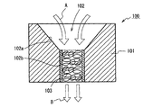
- a conventional inertial filter 100 will be described with reference to FIGS. 15A and 15B.
- a conventional inertial filter 100 is arranged in an airflow passage and can be classified, and includes a columnar filter body 101.
- the filter main body 101 includes a through hole 102 having a circular cross section penetrating from the upstream side to the downstream side of the airflow passage.
- the through hole 102 has a reduced diameter through hole 102a whose inner diameter gradually decreases from the upstream side to the downstream side of the air flow, and a constant diameter through hole having a constant inner diameter coupled to the reduced diameter through hole 102a on the downstream side. 102b.
- the constant diameter through hole 102b is filled with a metal fiber 103 which is an example of an incompressible fiber.
- the metal fiber 103 is prevented from coming off axially downward from the constant diameter through hole 102b by a mechanism not shown.
- an air flow is generated in the through hole 102 from the arrow A to the B direction in the through hole 102 by a pressure difference generated by reducing the internal pressure of the inertial filter 100 to the external pressure or less by the suction force of a pump (not shown). This allows the particles to be classified.
- the air flow speeds up in the reduced diameter through hole 102a and flows into the constant diameter through hole 102b and becomes constant.
- the fine particles included in the airflow in the constant diameter through hole 102b collide with the metal fiber 103 and are captured (collected).
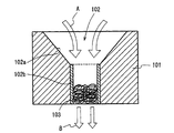
- FIG. 15A shows the inertial filter 100 shown in FIG. 15A, when the velocity of the airflow increases, the metal fiber 103 is compressed downward in the axial direction as shown in FIG. 15B due to the axial pressure received from the airflow.
- FIG. 15B shows the above compression in an exaggerated manner, and includes compression other than such a mode.
- the airflow gradually accelerates and then passes through the constant diameter throughhole 102b at a constant speed. Collect particles.
- the constant-diameter through hole 102b has a filter structure in which the metal fibers 103 are layered, it is possible to apply the Stokes number Stk and the Peclet number Pe that can be used to select the gas flow velocity and fiber diameter. it can.
- the Stokes number Stk is a dimensionless value representing the followability of particles to a gas flow in a filter having a metal fiber structure, and the Stokes number Stk is proportional to the flow velocity and the particle density. It is proportional to the power and inversely proportional to the fiber diameter.
- the particle size of the particles to be collected can be selected by controlling the gas flow rate and selecting the fiber diameter.
- the metal fiber 103 is not limited to the inertia of the particles, but also intercepts, gravity, Particles can also be collected by collecting electrostatic force, diffusion, and the like.
- the Peclet number Pe is a number that represents the ratio between the effect that particles are carried by airflow and the effect that particles are carried by diffusion, and is proportional to the flow velocity and fiber diameter and inversely proportional to the diffusion coefficient. In order to reduce the influence of diffusion, it is necessary to increase the Peclet number Pe. The smaller the particle size, the larger the diffusion coefficient and the smaller the fiber diameter is selected. Therefore, it can be seen that increasing the flow rate is preferable for increasing the particle size selectivity. From the above, by selecting the flow rate, fiber diameter, etc., the target particles can be collected or classified by the metal fibers.
- the constant-diameter through-hole is adjusted by adjusting the porosity by adjusting the filling amount of the metal fiber 103 in the constant-diameter through-hole 102 b and the fiber diameter of the metal fiber 103.
- the particle inertia effect necessary for particle removal can be obtained even if the small air flow suction pump is used to suck the flow.
- An object of the present invention is to provide an inertial filter capable of performing particle classification stably without reducing the collection efficiency over a long period of time even when the metal fiber in the constant-diameter through-hole receives pressure from the airflow. Yes.
- An inertial filter according to the present invention includes a filter body having an axial through hole, and incompressible fibers filled in the axial through hole, A holding mechanism capable of holding the incompressible fiber at a plurality of axial positions against an axial compressive force acting on the incompressible fiber when passing through the through hole is provided.
- the fluid includes not only gas but also liquid and others.
- the particles collected or captured by the inertia filter are not limited to particles floating in the gas, but may include other solvents such as particles floating in a liquid or others.
- the incompressible fiber can be preferably composed of metal fiber.
- the metal fibers are preferably stainless steel fibers, for example, but are not limited to stainless steel fibers, and may be one or more metal fibers selected from aluminum fibers, copper fibers, and other metal fibers.
- the non-compressible fiber may be a fiber that is non-compressible and hardly changes in volume even when a high-speed airflow passes, and is not limited to a metal fiber.
- the incompressible fiber is held at a plurality of positions in the axial direction by the holding mechanism even if it receives pressure in the fluid passing direction when passing the fluid, so that it does not need to be compressed in the axial direction.
- particle classification can be performed stably without lowering.
- the holding mechanism is A filter box inserted into the through hole from the axial direction; A plurality of wire beams locked to the filter box in a state of passing through the filter box in a radial direction from a plurality of axial positions; Including The incompressible fibers in the through holes are held by the plurality of wire beams penetrating the filter box in a state where the incompressible fibers are filled in the filter box.
- the incompressible fiber can be held so as not to be compressed by the wire beam of the holding mechanism even when the incompressible fiber is subjected to axial pressure in the fluid passage direction when passing the fluid. Even if it receives a pressure, it does not need to be compressed in the axial direction, and the particle classification can be performed stably without reducing the collection efficiency over a long period of time.
- the holding mechanism includes a fishbone shape body inserted in the through hole from the axial direction, The incompressible fiber in the through hole is held by the fishbone-shaped body in a state where the incompressible fiber is filled in the through hole.
- the fishbone-shaped body may be configured in a shape including, for example, a linear body extending linearly in the axial direction and a plurality of locking bodies extending radially outward from a plurality of axial positions of the linear body. it can.
- the holding mechanism includes a filter box inserted into the through hole from the axial direction,
- the fishbone-shaped body is arranged in the axial direction about the approximate center in the filter box.
- the holding mechanism is A filter box inserted as a side core into the through hole from the axial direction; A plurality of holding claws extending radially inward at a plurality of locations in the circumferential direction and axial direction on the inner peripheral surface of the filter box; Including The incompressible fibers in the through holes are held by the plurality of holding claws in a state where the incompressible fibers are filled in the filter box.
- the holding mechanism includes first and second holding mechanisms,
- the first holding mechanism includes a fishbone-shaped body inserted from the axial direction into the through-hole,
- the second holding mechanism is A filter box inserted as a side core into the through hole from the axial direction;
- a plurality of holding claws extending radially inward at a plurality of locations in the circumferential direction and the axial direction on the inner peripheral surface of the filter box;
- Including The incompressible fiber in the through hole is held by the fishbone-shaped body and the plurality of holding claws in a state where the incompressible fiber is filled in the through hole.
- an inertial filter capable of performing particle classification stably over a long period of time can be provided.
- FIG. 1 is a diagram showing a conceptual configuration of an inertial filter according to a first embodiment of the present invention as viewed from the side.
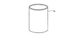
- FIG. 2 is an enlarged view showing the appearance of the filter box in the inertial filter of FIG.
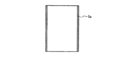
- FIG. 3 is a diagram showing a cross-sectional configuration of the filter box of FIG.
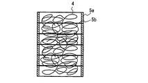
- FIG. 4 is a diagram illustrating a cross-sectional configuration of the filter box in a state in which the metal fiber is accommodated.
- FIG. 5A is a view (No. 1) showing a state in which a wire beam is inserted and attached to the filter box of FIG.
- FIG. 5B is a diagram (part 2) illustrating a state in which a wire beam is inserted and attached to the filter box of FIG.
- FIG. 5C is a diagram (No. 3) illustrating a state in which a wire beam is inserted and attached to the filter box of FIG.
- FIG. 6 is a diagram showing a conceptual configuration of the inertial filter according to the second embodiment of the present invention as viewed from the side.
- FIG. 7A is a diagram showing a cross-sectional configuration of a filter box in the inertial filter of FIG.
- FIG. 7B is a diagram showing an external configuration of a holding mechanism in the inertial filter of FIG.
- FIG. 8A is a diagram illustrating a state in which the holding mechanism in which the metal fiber is entangled with the filter box is housed.
- FIG. 8B is a diagram illustrating a state in which the holding mechanism is housed in the filter box.
- FIG. 9 is a diagram showing a conceptual configuration of the inertial filter according to the third embodiment of the present invention as viewed from the side.
- FIG. 10 is a diagram showing a cross-sectional configuration of a filter box in the inertial filter of FIG.
- FIG. 11A is a diagram illustrating a planar configuration of the filter box.
- FIG. 11B is a diagram illustrating a state in which the holding claws are protruded from the filter box.
- FIG. 11C is a diagram in which metal fibers are arranged in a mat shape on the filter box of FIG. 11B.
- FIG. 11D is a diagram illustrating a state in which the filter box is wound.
- FIG. 11A is a diagram illustrating a planar configuration of the filter box.
- FIG. 11B is a diagram illustrating a state in which the holding claws are protruded from the filter box.
- FIG. 11C is a diagram in which metal fibers are arranged in a mat shape on the filter box
- FIG. 12 is a diagram showing a conceptual configuration of an inertial filter according to the fourth embodiment of the present invention as viewed from the side.
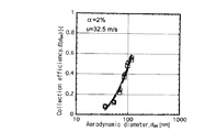
- FIG. 13A is a diagram illustrating the characteristics of Comparative Example 1.
- FIG. 13B is a diagram illustrating characteristics of the embodiment of the present invention.
- FIG. 14A is a diagram illustrating the characteristics of Comparative Example 2.
- FIG. 14B is a diagram showing characteristics of the embodiment of the present invention.
- FIG. 15A is a view showing a configuration of a conventional inertial filter as seen from the side, in which airflow flows and particles are collected.
- FIG. 15B is a diagram illustrating a state in which metal fibers are compressed by airflow in a conventional inertial filter.
- the particles are assumed to be particles floating in the gas as an example of the solvent.
- the particles are not limited to the particles floating in the gas, but include other solvents such as particles floating in the liquid or others. Can do. Of course, the same applies to other embodiments.
- the inertial filter 1 of the first embodiment includes a columnar filter body 2.
- the filter body 2 is made of a material made of, for example, an aluminum material or a SUS material, and includes an axial through hole 3.
- the airflow flows in from the arrow A with the upper side in the drawing as the airflow passage upstream side, and flows out in the arrow B direction as the airflow passage downstream side in the lower side.
- This airflow is generated by an airflow suction action to the through hole 3 by an airflow suction pump (not shown) arranged on the downstream side of the airflow.
- the through hole 3 has a reduced diameter through hole 3a whose inner diameter gradually decreases from the air flow passage upstream side to the downstream side, and a constant diameter through hole 3b which is continuous on the air flow passage downstream side of the reduced diameter through hole 3a and has a constant inner diameter. Is composed of.
- the constant diameter through holes 3b are filled with metal fibers 4 that hardly change in volume even when a high-speed airflow passes as incompressible fibers.
- the metal fibers 4 are preferably SUS (stainless) fibers, but are not limited to SUS fibers, and may be one or more metal fibers selected from aluminum fibers, copper fibers, and other metal fibers. Further, the fibers are not limited to metal fibers as long as they are fibers that are incompressible and hardly change in volume even when a high-speed airflow passes through them.
- the metal fibers 4 can be held at a plurality of positions in the axial direction against the axial compression force acting on the metal fibers 4 when the airflow passes through the constant diameter through-holes 3b.
- a holding mechanism 5 is provided.
- the holding mechanism 5 includes a filter box 5a inserted in the constant diameter through hole 3b from the axial direction, and a plurality of wires locked to the filter box 5a in a state of passing through the filter box 5a in a radial direction from a plurality of axial positions. Beam 5b.
- the wire beam 5b passes through the filter box 5a in a state where the filter box 5a is filled with the metal fibers 4, and holds the metal fibers 4 in the constant diameter through hole 3b at a plurality of positions in the axial direction in this through state. Be able to.
- FIGS. 2 to 5C show the appearance of the filter box 5a in the inertial filter 1 of FIG. 1
- FIG. 3 shows the cross-sectional configuration of the filter box 5a of FIG. 2
- FIG. 4 shows the cross section of the filter box 5a in a state in which the metal fibers 4 are housed.
- 5A, 5B, and 5C show a state in which the wire beam 5b is inserted and attached to the filter box 5a of FIG.
- the filter box 5a is a cylindrical box as shown in FIGS. 2 and 3, and the metal fiber 4 is filled in the filter box 5a as shown in FIG.
- the filter box 5a has an outer diameter substantially the same as the inner diameter of the constant diameter through hole 3b, and an axial length corresponding to the through hole depth of the constant diameter through hole 3b.
- Examples of the material of the filter box 5a include SUS, Cu, aluminum, and alloys thereof. Among them, SUS is preferable.
- a plurality of wire beams 5b are inserted into the filter box 5a at substantially equal intervals in the axial direction, and are locked to the filter box 5a.
- the metal fibers 4 are held at a plurality of positions in the axial direction by the wire beams 5b.
- the filter box 5a in the state of FIG. 5C is inserted into the constant diameter through hole 3b as shown in FIG.
- the metal fiber 4 when the airflow flows in from the arrow A and is discharged as shown by the arrow B, the metal fiber 4 is subjected to the axial pressure from the airflow passage upstream side when the airflow passes.
- the metal fibers 4 since the metal fibers 4 are held at a plurality of positions in the axial direction by the wire beams 5b of the holding mechanism 5, the metal fibers 4 need not be compressed in the axial direction.
- the size and abundance of the voids existing between the metal fibers 4 are not affected so much as to greatly affect the particle collection efficiency, so that the collection efficiency does not decrease over a long period of time and the particle classification is stable. It is possible to provide the inertial filter 1 capable of performing the above.
- FIGS. 6 to 8 The inertial filter according to the second embodiment of the present invention will be described with reference to FIGS. 6 to 8, parts corresponding to those in FIGS. 1 to 5C are denoted by the same reference numerals, and detailed description of the parts corresponding to the same numerals is omitted.
- the configuration different from the first embodiment will be mainly described.
- the inertial filter 11 of the second embodiment has a constant diameter penetration as in the first embodiment.
- a holding mechanism 51 is provided that can hold the metal fiber 4 at a plurality of positions in the axial direction against the axial compression force acting on the metal fiber 4 when the airflow passes through the hole 3b.
- the holding mechanism 51 includes a cylindrical filter box 51a as in the first embodiment.
- the holding mechanism 51 is substantially the same in the filter box 51a.
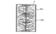
- a fishbone shaped body 51b is arranged in the axial direction at the center.
- the fishbone-shaped body 51b includes a linear body 51b1 extending in the axial direction, and a plurality of locking bodies 51b2 extending radially outward from a plurality of axial positions of the linear body 51b1.
- the metal fibers 4 are held at a plurality of positions in the axial direction by the plurality of locking bodies 51b2 provided in the fishbone-shaped body 51b, and thereby, when the airflow passes through the constant-diameter through holes 3b, The metal fiber 4 can be held against the acting axial compression force.
- the holding mechanism 51 is configured by inserting the fishbone-shaped body 51b (see FIG. 8A) in a state where the metal fibers 4 are entangled into the filter box 51a from the upper side in the axial direction ( (See FIG. 8B).
- the fishbone-shaped body 51b is not locked to the inner peripheral surface of the filter box 51a. Even in such a structure, the fishbone-shaped body 51b sufficiently fulfills the function of holding the metal fibers 4. However, the fishbone shaped body 51b may be locked to the inner peripheral surface of the filter box 51a. Then, the fishbone shaped body 51b can be reliably positioned and fixed in the filter box 51a, and the function of holding the metal fibers 4 is further enhanced.
- the metal fiber 4 is passed through the airflow passage upstream side when the airflow passes.
- the metal fibers 4 are held at a plurality of positions in the axial direction by the plurality of locking bodies 51b2 of the fishbone-shaped body 51b of the holding mechanism 51, so that they are not compressed in the axial direction.
- the size and abundance of the voids existing between the metal fibers 4 are not affected so much as to greatly affect the particle collection efficiency, so that the collection efficiency does not decrease over a long period of time and the particle classification is stable. It is possible to provide the inertial filter 11 capable of performing the above.
- the inertial filter according to the third embodiment of the present invention will be described with reference to FIGS. 9 to 11, the same reference numerals are given to the portions corresponding to those in FIGS. 1 to 8, and detailed description of the portions corresponding to the same reference numerals is omitted.
- the description will focus on the configuration different from that of the first embodiment.
- the inertial filter 12 of the third embodiment has a constant diameter penetration as in the first embodiment.
- a holding mechanism 52 is provided that can hold the metal fibers 4 at a plurality of positions in the axial direction against the axial compression that the metal fibers 4 receive when the airflow passes through the holes 3b.
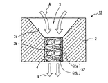
- the holding mechanism 52 includes a filter box 52a as a side core and a plurality of holding claws 52b provided on the inner peripheral surface of the filter box 52a.
- the holding mechanism 52 will be described with reference to FIG. 10 and FIGS. 11A to 11D.
- the holding mechanism 52 of the third embodiment includes a cylindrical filter box 52a as in the first embodiment. Unlike the first embodiment, a plurality of holding claws 52b are formed on the inner peripheral surface of the filter box 52a.
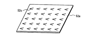
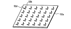
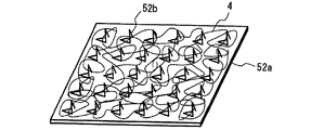
- the filter box 52a When the filter box 52a is unfolded as shown in FIG. 11A, the filter box 52a has a rectangular sheet shape in plan view, and is provided with a number of cuts 52c for forming the holding claws 52b. Then, as shown in FIG. 11B, the holding claw 52b is formed by raising the notch 52c. 52d indicates a hole formed after raising the holding claw 52b. 11C, the metal fibers 4 are arranged in a mat shape on the filter box 52a of FIG. 11B, and then the filter box 52a is rolled as shown in FIG. 11D. The holding mechanism 52 manufactured in this way is inserted into the constant diameter through hole 3b as shown in FIG.
- the metal fiber 4 passes from the upstream side of the airflow when the airflow passes.
- the metal fiber 4 is held at a plurality of positions in the axial direction by the holding claws 52b of the holding mechanism 52, so that it does not need to be compressed in the axial direction.
- the size and abundance of the voids existing between the metal fibers 4 are not affected so much as to greatly affect the particle collection efficiency, so that the collection efficiency does not decrease over a long period of time and the particle classification is stable. It is possible to provide the inertial filter 12 capable of performing the following.
- the inertial filter according to the fourth embodiment of the present invention will be described with reference to FIG. 12, portions corresponding to those in FIGS. 1 to 11 are denoted by the same reference numerals, and detailed description of the portions corresponding to the same reference numerals is omitted.
- the inertial filter 13 according to the fourth embodiment includes a holding mechanism 53 in which the holding mechanisms 51 and 52 of the second and third embodiments are combined. That is, the inertial filter 13 of the fourth embodiment holds the metal fiber 4 at a plurality of axial positions against the axial compression force that the metal fiber 4 receives when the airflow passes through the constant diameter through hole 3b. A holding mechanism 53 is obtained.
- the holding mechanism 53 includes a filter box 53a, a fishbone-shaped body 53b, and a plurality of holding claws 53c on the inner peripheral surface of the filter box 53a. Since the fishbone-shaped body 53b and the holding claws 53c have been described in the second and third embodiments, the details thereof will be omitted.
- the metal fiber 4 when the airflow flows in from the arrow A and is discharged as shown by the arrow B, the metal fiber 4 has an airflow when passing through the airflow.
- the metal fiber 4 is held at a plurality of locations in the axial direction by the fishbone-shaped body 53b of the holding mechanism 53 and the holding claws 53c, so that it does not have to be compressed in the axial direction. .
- the size and abundance of the voids existing between the metal fibers 4 are not affected so much as to greatly affect the particle collection efficiency, so that the collection efficiency does not decrease over a long period of time and the particle classification is stable. It is possible to provide the inertial filter 13 capable of performing the following.
- the metal fibers 4 are filled in the constant diameter through hole 3b at a filling rate of 0.4% (FIG. 13A) and 2.0% (FIG. 14A) without providing the holding mechanisms 5, 51, 52, 53.
- FIG. 13B and FIG. 14B The change of the classification characteristic before and after dust deposition in the filled comparative examples 1 and 2 is shown. 13B and FIG. 14B, the holding mechanism 5, 51, 52, 53 is provided, and the metal fiber 4 is filled with a constant diameter through hole 3b at a filling rate of 0.3% (FIG. 13B) and 2.0% (FIG. 14B).
- FIG. 13A and 14A The change of the classification characteristics before and after dust deposition in the embodiment of the present invention filled in FIG.
- the present invention is an inertial filter that classifies and collects particles by causing particles in an air current to collide with the incompressible fibers when a fluid such as an air current passes through a through hole filled with the incompressible fibers. It is particularly useful.
Landscapes
- Chemical & Material Sciences (AREA)
- Chemical Kinetics & Catalysis (AREA)
- Biochemistry (AREA)
- Health & Medical Sciences (AREA)
- Life Sciences & Earth Sciences (AREA)
- Analytical Chemistry (AREA)
- Physics & Mathematics (AREA)
- General Health & Medical Sciences (AREA)
- General Physics & Mathematics (AREA)
- Immunology (AREA)
- Pathology (AREA)
- Dispersion Chemistry (AREA)
- Filtering Materials (AREA)
- Combined Means For Separation Of Solids (AREA)
Abstract
貫通孔を備えたフィルタ本体と、貫通孔に充填された非圧縮性繊維とを備え、貫通孔内を流体通過時に非圧縮性繊維が受ける軸方向圧縮に抗して当該非圧縮性繊維を軸方向複数箇所で保持し得る保持機構を具備することで、長期にわたり安定して粒子分級を行うことができる慣性フィルタ。
Description
本発明は、非圧縮性繊維を充填した貫通孔内に気流等の流体を通過させる際に非圧縮性繊維に気流中の粒子を衝突させることにより粒子を分級捕集するようにした慣性フィルタに関するものである。
図15A、図15Bを参照して従来の慣性フィルタ100を説明する。従来の慣性フィルタ100は、気流通過路内に配置されて粒子分級することができるものであり、円柱状のフィルタ本体101を備える。フィルタ本体101は、気流通過上流側から下流側方向にかけて貫通した断面円形の貫通孔102を具備する。この貫通孔102は、内径が気流通過上流側から下流側に向けて漸次縮径する縮径貫通孔102aと、この縮径貫通孔102aに下流側で連成される内径一定の定径貫通孔102bとを含む。この定径貫通孔102b内に、非圧縮性繊維の一例である金属繊維103が充填されている。金属繊維103は図示略の機構により定径貫通孔102bから軸方向下方へ抜け止めされている。
この慣性フィルタ100では、図示略のポンプの吸引力により、慣性フィルタ100の内圧を外圧以下に下げて両圧力で生成する気圧差で貫通孔102内に図中矢印AからB方向へ気流を発生させて粒子を分級させることができるようになっている。上記気流は、縮径貫通孔102a内で速度上昇して定径貫通孔102b内に流入して一定となる。そして、定径貫通孔102b内において気流に含む微粒子は金属繊維103に衝突して捕捉(捕集)される。
図15Aで示す慣性フィルタ100においては、気流の速度が上昇すると、金属繊維103が気流から受ける軸方向圧力により、図15Bで示すように軸方向下方へ圧縮されてしまう。ただし、図15Bは上記圧縮を誇張して示しており、このような態様以外の圧縮も含む。
以下、さらに詳細に説明する。まず、慣性フィルタ100の縮径貫通孔102aは気流下流側方向へ内径が小さくなっていくので、気流は徐々に加速した後、定径貫通孔102bを一定速度で通過し、この通過の際に粒子を捕集する。定径貫通孔102bは金属繊維103が層状になったフィルタ構造になっているので、気体の流速、繊維径の選択に用いることができるストークス数Stkと、ペクレ数Peと、を適用することができる。ストークス数Stkは、金属繊維構造のフィルタ内での、気体の流れに対する粒子の追従性を表す無次元の値であり、また、ストークス数Stkは、流速、粒子密度に比例し、粒径の2乗に比例し、繊維径に反比例する。
ストークス数Stkの式によると、気体の流速が大きくなるに従い、粒径が大きい浮遊粒子から順に気体の運動に追従できなくなり、気体の流路から外れて金属繊維103と衝突するようになる。このストークス数Stkを参考にしつつ、気体の流速を制御することと、繊維径を選択することとにより、捕集目的の粒子の粒径を選択することができる。
上記従来の慣性フィルタ100においては、金属繊維103の繊維径は極めて小さいので、インパクタほど気流の流速を大きくする必要がなく、また、金属繊維103は、粒子の慣性だけではなく、さえぎり、重力、静電気力、拡散などの捕集によっても粒子を捕集することができる。
ペクレ数Peは、気流により粒子が運ばれる効果と、拡散によって粒子が運ばれる効果との比率を表す数であり、流速、繊維径に比例し、拡散係数に反比例する。拡散の影響を少なくするには、ペクレ数Peを大きくする必要がある。粒径が小さいほど、拡散係数が大きくなり、繊維径は小さい値が選択されているので、流速を高めることが粒径の選択性を高めることに好ましいことがわかる。以上から、流速、繊維径等を選択することで、目的とする粒子を金属繊維により捕集ないし分級することができる。
そして、従来のこの種の慣性フィルタ100では、特に、定径貫通孔102b内の金属繊維103の充填量調整により空隙率調整を行うことと、金属繊維103の繊維径とにより、定径貫通孔102b内における気流流通性を大きく低下させず圧損を小さく抑制した結果、小型の気流吸引ポンプで小流量吸引しても粒子除去に必要な粒子慣性効果を得られる。
したがって、上記の慣性フィルタ100が、図15Bで示すように、軸方向下方へ圧縮されて金属繊維103相互の間隔が減少したのでは、空隙率が大きく変化してしまい、圧損が大きくなるなどして、粒子の捕集効率が所期通りのものとならず、低下することが判る。
本発明は、定径貫通孔内の金属繊維が気流から圧力を受けても長期にわたり捕集効率が低下することがなく安定して粒子分級を行うことができる慣性フィルタを提供することを目的としている。
本発明による慣性フィルタは、軸方向の貫通孔を有するフィルタ本体と、上記軸方向貫通孔に充填された非圧縮性繊維とを備え、
上記貫通孔内を流体通過時に上記非圧縮性繊維に作用する軸方向圧縮力に抗して上記非圧縮性繊維を軸方向複数箇所で保持し得る保持機構を具備した。なお、上記流体には気体に限らず、液体、その他のものを含む。この慣性フィルタで捕集ないし捕捉される粒子は、気体中に浮遊する粒子に限定されず、他の溶媒例えば液中やその他を浮遊する粒子を含むことができる。
上記貫通孔内を流体通過時に上記非圧縮性繊維に作用する軸方向圧縮力に抗して上記非圧縮性繊維を軸方向複数箇所で保持し得る保持機構を具備した。なお、上記流体には気体に限らず、液体、その他のものを含む。この慣性フィルタで捕集ないし捕捉される粒子は、気体中に浮遊する粒子に限定されず、他の溶媒例えば液中やその他を浮遊する粒子を含むことができる。
上記非圧縮性繊維は好ましくは金属繊維で構成することができる。また金属繊維として例えばステンレス繊維が好ましいが、ステンレス繊維に限定するものではなく、アルミ繊維、銅繊維、その他の金属繊維から選ばれる1種以上の金属繊維でもよい。また、非圧縮性繊維は、非圧縮性で高速気流が通過しても体積変化が殆どない繊維であればよく、金属繊維に限定されない。
本発明では、非圧縮性繊維は流体通過に際して流体通過方向の圧力を受けても上記保持機構により軸方向複数箇所で保持されているので軸方向に圧縮されずに済む結果、長期にわたり捕集効率が低下することがなく安定して粒子分級を行うことができるようになる。
好ましい態様では、上記保持機構は、
上記貫通孔に軸方向から挿入されたフィルタボックスと、
上記フィルタボックスを軸方向複数箇所からそれぞれ半径方向に貫通した状態で上記フィルタボックスに係止した複数のワイヤ梁と、
を含み、
上記フィルタボックス内に上記非圧縮性繊維が充填された状態で上記フィルタボックスを貫通した上記複数のワイヤ梁により上記貫通孔内の非圧縮性繊維が保持されている。
上記貫通孔に軸方向から挿入されたフィルタボックスと、
上記フィルタボックスを軸方向複数箇所からそれぞれ半径方向に貫通した状態で上記フィルタボックスに係止した複数のワイヤ梁と、
を含み、
上記フィルタボックス内に上記非圧縮性繊維が充填された状態で上記フィルタボックスを貫通した上記複数のワイヤ梁により上記貫通孔内の非圧縮性繊維が保持されている。
この態様では、非圧縮性繊維が流体通過に際して流体通過方向の軸方向圧力を受けても保持機構のワイヤ梁により圧縮されないように保持することができるので、非圧縮性繊維は流体通過に際して軸方向圧力を受けても軸方向に圧縮されずに済み、長期にわたり捕集効率が低下することがなく安定して粒子分級を行うことができるようになる。
別の好ましい態様では、上記保持機構は、上記貫通孔に軸方向から挿入されたフィッシュボーン形状体を含み、
上記貫通孔内に上記非圧縮性繊維が充填された状態で上記フィッシュボーン形状体により上記貫通孔内の上記非圧縮性繊維が保持されている。
上記貫通孔内に上記非圧縮性繊維が充填された状態で上記フィッシュボーン形状体により上記貫通孔内の上記非圧縮性繊維が保持されている。
上記フィッシュボーン形状体は、例えば軸方向線状に延びる線状体と、この線状体の軸方向複数箇所から半径方向外向きに延びる複数の係止体と、を含む形状で構成することができる。
さらに別の好ましい態様では、上記保持機構は、上記貫通孔に軸方向から挿入されたフィルタボックスを含み、
上記フィッシュボーン形状体が上記フィルタボックス内の略中心を軸方向に配置されている。
上記フィッシュボーン形状体が上記フィルタボックス内の略中心を軸方向に配置されている。
さらに別の好ましい態様では、上記保持機構は、
上記貫通孔に軸方向からサイドコアとして挿入されたフィルタボックスと、
上記フィルタボックス内周面上の円周方向および軸方向の複数箇所に半径方向内向きに延びる複数の保持爪と、
を含み、
上記フィルタボックス内に上記非圧縮性繊維が充填された状態で上記複数の保持爪により上記貫通孔内の上記非圧縮性繊維が保持されている。
上記貫通孔に軸方向からサイドコアとして挿入されたフィルタボックスと、
上記フィルタボックス内周面上の円周方向および軸方向の複数箇所に半径方向内向きに延びる複数の保持爪と、
を含み、
上記フィルタボックス内に上記非圧縮性繊維が充填された状態で上記複数の保持爪により上記貫通孔内の上記非圧縮性繊維が保持されている。
さらに別の好ましい態様では、上記保持機構は、第1、第2の保持機構を含み、
上記第1の保持機構は、上記貫通孔に軸方向から挿入されたフィッシュボーン形状体を含み、
上記第2の保持機構は、
上記貫通孔に軸方向からサイドコアとして挿入されたフィルタボックスと、
上記フィルタボックス内周面上の円周方向および軸方向の複数箇所に半径方向内向きに延びる複数の保持爪と、
を含み、
上記貫通孔内に上記非圧縮性繊維が充填された状態で上記フィッシュボーン形状体と上記複数の保持爪とにより上記貫通孔内の上記非圧縮性繊維が保持されている。
上記第1の保持機構は、上記貫通孔に軸方向から挿入されたフィッシュボーン形状体を含み、
上記第2の保持機構は、
上記貫通孔に軸方向からサイドコアとして挿入されたフィルタボックスと、
上記フィルタボックス内周面上の円周方向および軸方向の複数箇所に半径方向内向きに延びる複数の保持爪と、
を含み、
上記貫通孔内に上記非圧縮性繊維が充填された状態で上記フィッシュボーン形状体と上記複数の保持爪とにより上記貫通孔内の上記非圧縮性繊維が保持されている。
本発明によれば、長期にわたり安定して粒子分級を行うことができる慣性フィルタを提供することができる。
以下、添付した図面を参照して、本発明の実施の形態に係る慣性フィルタを説明する。
(実施の形態1)
図1ないし図5Cを参照して本発明の実施の形態1にかかる慣性フィルタを説明する。なお、実施の形態1において粒子は溶媒の一例として気体中に浮遊する粒子を想定するが、気体中に浮遊する粒子に限定されず、他の溶媒例えば液中やその他を浮遊する粒子を含むことができる。もちろん、他の実施の形態においても同様である。
図1ないし図5Cを参照して本発明の実施の形態1にかかる慣性フィルタを説明する。なお、実施の形態1において粒子は溶媒の一例として気体中に浮遊する粒子を想定するが、気体中に浮遊する粒子に限定されず、他の溶媒例えば液中やその他を浮遊する粒子を含むことができる。もちろん、他の実施の形態においても同様である。
まず図1を参照して、実施の形態1の慣性フィルタ1は、円柱状のフィルタ本体2を備える。このフィルタ本体2は例えばアルミニウム材やSUS材からなる材料で作られており、軸方向の貫通孔3を具備する。この貫通孔3内には図で上側を気流通過上流側として気流が矢印Aから流入し、下側に気流通過下流側として矢印B方向へと流出する。この気流は、気流下流側に配置した図示略の気流吸引ポンプによる貫通孔3への気流吸入作用により発生するようになっている。貫通孔3は気流通過上流側から下流側へ内径が漸次に縮径する縮径貫通孔3aと、縮径貫通孔3aの気流通過下流側で連続し内径が一定である定径貫通孔3bと、から構成される。
定径貫通孔3bには非圧縮性繊維として高速気流が通過しても体積変化が殆どない金属繊維4が充填される。この金属繊維4は好ましくはSUS(ステンレス)繊維であるが、SUS繊維に限定するものではなく、アルミ繊維、銅繊維、その他の金属繊維から選ばれる1種以上の金属繊維でもよい。また、非圧縮性で高速気流が通過しても体積変化が殆どない繊維であれば、金属繊維に限定しない。
以上の構成において実施の形態1では、定径貫通孔3b内を気流が通過する際に金属繊維4に作用する軸方向圧縮力に抗して当該金属繊維4を軸方向複数箇所で保持し得る保持機構5を具備する。
保持機構5は、定径貫通孔3bに軸方向から挿入されたフィルタボックス5aと、このフィルタボックス5aを軸方向複数箇所からそれぞれ半径方向に貫通した状態でフィルタボックス5aに係止した複数のワイヤ梁5bとを含む。
ワイヤ梁5bは、フィルタボックス5a内に金属繊維4が充填された状態でフィルタボックス5aを貫通しており、この貫通状態で定径貫通孔3b内の金属繊維4を軸方向複数箇所で保持することができるようになっている。
図2ないし図5Cを参照して保持機構5の製作を説明する。図2は図1の慣性フィルタ1におけるフィルタボックス5aの外観を示し、図3は図2のフィルタボックス5aの断面構成を示し、図4は金属繊維4を収納した状態でのフィルタボックス5aの断面構成を示し、図5A、図5B、図5Cは図4のフィルタボックス5aにワイヤ梁5bを差し込んで取り付けていく状態を示す。
フィルタボックス5aは図2、図3で示すように円筒状のボックスであり、このフィルタボックス5a内には図4で示すように金属繊維4が充填される。フィルタボックス5aは外径が定径貫通孔3bの内径に略同一であり、また、軸方向長さが定径貫通孔3bの貫通孔深さに対応している。フィルタボックス5aの材料にはSUS,Cu,アルミ二ウムやこれらの合金類があるが、それらの中ではSUSが好ましい。
そして、図5A~図5Cで順次に示すように複数のワイヤ梁5bをフィルタボックス5aに軸方向略等間隔で差し込むようにして貫通させてフィルタボックス5aに係止させる。そして、この状態で金属繊維4はワイヤ梁5bにより軸方向複数箇所で保持される。そして、この図5Cの状態のフィルタボックス5aを図1で示すように定径貫通孔3b内に挿入する。
実施の形態1では、図1で示すように、気流が矢印Aから流入し、矢印Bで示すように排出されていく際、金属繊維4には気流通過に際して気流通過上流側から軸方向圧力を受けるが、金属繊維4は保持機構5のワイヤ梁5bにより軸方向複数箇所で保持されているので、軸方向に圧縮されずに済む。その結果、金属繊維4相互間に存在する空隙の大きさ、存在率は、粒子捕集効率に大きく影響するほどの変化を受けなくなり、これにより長期にわたり捕集効率が低下せず安定した粒子分級を行うことができる慣性フィルタ1を提供することができる。
(実施の形態2)
図6ないし図8を参照して本発明の実施の形態2にかかる慣性フィルタを説明する。図6ないし図8において図1ないし図5Cと対応する部分には同一の符号を付し、同一の符号にかかる部分の詳細な説明は略する。実施の形態2においては、実施の形態1と相違する構成を中心にして説明すると、図6で示すように、実施の形態2の慣性フィルタ11は、実施の形態1と同様に、定径貫通孔3b内を気流が通過する際に金属繊維4に作用する軸方向圧縮力に抗して当該金属繊維4を軸方向複数箇所で保持し得る保持機構51を具備する。
図6ないし図8を参照して本発明の実施の形態2にかかる慣性フィルタを説明する。図6ないし図8において図1ないし図5Cと対応する部分には同一の符号を付し、同一の符号にかかる部分の詳細な説明は略する。実施の形態2においては、実施の形態1と相違する構成を中心にして説明すると、図6で示すように、実施の形態2の慣性フィルタ11は、実施の形態1と同様に、定径貫通孔3b内を気流が通過する際に金属繊維4に作用する軸方向圧縮力に抗して当該金属繊維4を軸方向複数箇所で保持し得る保持機構51を具備する。
この保持機構51は、図7A、図7Bで示すように、実施の形態1と同様に円筒状のフィルタボックス51aを具備する一方で、実施の形態1とは異なって、フィルタボックス51a内の略中心を軸方向にフィッシュボーン形状体51bを配置している。フィッシュボーン形状体51bは、軸方向線状に延びる線状体51b1と、この線状体51b1の軸方向複数箇所から半径方向外向きに延びる複数の係止体51b2とを含む。この保持機構51ではフィッシュボーン形状体51bが備える複数の係止体51b2により金属繊維4を軸方向複数箇所で保持し、これにより定径貫通孔3b内を気流が通過する際に金属繊維4に作用する軸方向圧縮力に抗して当該金属繊維4を保持することができる。
なお、この保持機構51においては、金属繊維4が絡んだ状態のフィッシュボーン形状体51b(図8A参照)を、軸方向上側からフィルタボックス51aに挿入することで、保持機構51が構成される(図8B参照)。
また、この保持機構51においてフィッシュボーン形状体51bは、フィルタボックス51aの内周面に係止されていない。このような構造においてもフィッシュボーン形状体51bは、金属繊維4を保持する機能を十分に果たす。しかしながら、フィッシュボーン形状体51bを、フィルタボックス51aの内周面に係止させてもよい。そうすれば、フィッシュボーン形状体51bを確実にフィルタボックス51a内で位置決め固定できるようになって、金属繊維4を保持する機能がさらに高まる。
以上説明した実施の形態2においては、図6で示すように、気流が矢印Aから流入し、矢印Bで示すように排出されていく際、金属繊維4には気流通過に際して気流通過上流側から軸方向圧力を受けるが、金属繊維4は保持機構51のフィッシュボーン形状体51bの複数の係止体51b2により軸方向複数箇所で保持されているので、軸方向に圧縮されずに済む。その結果、金属繊維4相互間に存在する空隙の大きさ、存在率は、粒子捕集効率に大きく影響するほどの変化を受けなくなり、これにより長期にわたり捕集効率が低下せず安定した粒子分級を行うことができる慣性フィルタ11を提供することができる。
(実施の形態3)
図9ないし図11を参照して本発明の実施の形態3にかかる慣性フィルタを説明する。図9ないし図11において図1ないし図8と対応する部分には同一の符号を付し、同一の符号にかかる部分の詳細な説明は略する。実施の形態3においては、実施の形態1と相違する構成を中心にして説明すると、図9で示すように、実施の形態3の慣性フィルタ12は、実施の形態1と同様に、定径貫通孔3b内を気流が通過する際に金属繊維4が受ける軸方向圧縮に抗して当該金属繊維4を軸方向複数箇所で保持し得る保持機構52を具備する。保持機構52は、サイドコアとしてのフィルタボックス52aと、フィルタボックス52aの内周面に設けられた複数の保持爪52bとを含む。
図9ないし図11を参照して本発明の実施の形態3にかかる慣性フィルタを説明する。図9ないし図11において図1ないし図8と対応する部分には同一の符号を付し、同一の符号にかかる部分の詳細な説明は略する。実施の形態3においては、実施の形態1と相違する構成を中心にして説明すると、図9で示すように、実施の形態3の慣性フィルタ12は、実施の形態1と同様に、定径貫通孔3b内を気流が通過する際に金属繊維4が受ける軸方向圧縮に抗して当該金属繊維4を軸方向複数箇所で保持し得る保持機構52を具備する。保持機構52は、サイドコアとしてのフィルタボックス52aと、フィルタボックス52aの内周面に設けられた複数の保持爪52bとを含む。
保持機構52を図10および図11A~図11Dを参照して説明すると、実施の形態3の保持機構52は、実施の形態1と同様に円筒状のフィルタボックス52aを具備する一方で、実施の形態1とは異なって、フィルタボックス52aの内周面に複数の保持爪52bが形成されて構成されている。
フィルタボックス52aは、図11Aで示すように展開すると平面視矩形シート形状をなし、それらには保持爪52b形成用の切り込み52cが多数形成されている。そして、図11Bで示すように切り込み52cを立ち起こすことで保持爪52bが形成される。52dは保持爪52bを起こした後に形成される孔を示す。そして図11Cで示すように図11Bのフィルタボックス52a上に金属繊維4をマット状に配置し、ついで、図11Dで示すようにフィルタボックス52aを丸める。こうして製作された保持機構52は図9で示すように定径貫通孔3bに挿入される。
以上説明した実施の形態3においては、図9で示すように、気流が矢印Aから流入し、矢印Bで示すように排出されていく際、金属繊維4には気流通過に際して気流通過上流側から軸方向圧力を受けるが、金属繊維4は保持機構52の保持爪52bにより軸方向複数箇所で保持されているので、軸方向に圧縮されずに済む。その結果、金属繊維4相互間に存在する空隙の大きさ、存在率は、粒子捕集効率に大きく影響するほどの変化を受けなくなり、これにより長期にわたり捕集効率が低下せず安定した粒子分級を行うことができる慣性フィルタ12を提供することができる。
(実施の形態4)
図12を参照して本発明の実施の形態4にかかる慣性フィルタを説明する。図12において図1ないし図11と対応する部分には同一の符号を付し、同一の符号にかかる部分の詳細な説明は略する。実施の形態4の慣性フィルタ13においては、実施の形態2と実施の形態3との保持機構51,52を複合化した保持機構53を具備する。すなわち、実施の形態4の慣性フィルタ13は、定径貫通孔3b内を気流が通過する際に金属繊維4が受ける軸方向圧縮力に抗して当該金属繊維4を軸方向複数箇所で保持し得る保持機構53を具備する。この保持機構53は、フィルタボックス53aと、フィッシュボーン形状体53bと、フィルタボックス53a内周面の複数の保持爪53cとを含む。これらフィッシュボーン形状体53bおよび保持爪53cに関しては実施の形態2、実施の形態3で説明したから、その詳細は略する。
図12を参照して本発明の実施の形態4にかかる慣性フィルタを説明する。図12において図1ないし図11と対応する部分には同一の符号を付し、同一の符号にかかる部分の詳細な説明は略する。実施の形態4の慣性フィルタ13においては、実施の形態2と実施の形態3との保持機構51,52を複合化した保持機構53を具備する。すなわち、実施の形態4の慣性フィルタ13は、定径貫通孔3b内を気流が通過する際に金属繊維4が受ける軸方向圧縮力に抗して当該金属繊維4を軸方向複数箇所で保持し得る保持機構53を具備する。この保持機構53は、フィルタボックス53aと、フィッシュボーン形状体53bと、フィルタボックス53a内周面の複数の保持爪53cとを含む。これらフィッシュボーン形状体53bおよび保持爪53cに関しては実施の形態2、実施の形態3で説明したから、その詳細は略する。
以上説明した実施の形態4の慣性フィルタ13においては、図12で示すように、気流が矢印Aから流入し、矢印Bで示すように排出されていく際、金属繊維4には気流通過に際して気流通過上流側から軸方向圧力を受けるが、金属繊維4は保持機構53のフィッシュボーン形状体53bと、保持爪53cとにより軸方向複数箇所で保持されているので、軸方向に圧縮されずに済む。その結果、金属繊維4相互間に存在する空隙の大きさ、存在率は、粒子捕集効率に大きく影響するほどの変化を受けなくなり、これにより長期にわたり捕集効率が低下せず安定した粒子分級を行うことができる慣性フィルタ13を提供することができる。
本発明の各実施の形態の効果を、図13A~図14Bを参照してさらに詳細に説明する。図13A、図14Aは、保持機構5,51,52,53を設けることなく金属繊維4を充填率0.4%(図13A)、2.0%(図14A)で定径貫通孔3bに充填した比較例1、2における粉塵堆積前後の分級特性の変移を示す。図13B、図14Bは、保持機構5,51,52,53を設けたうえで金属繊維4を充填率0.3%(図13B)、2.0%(図14B)で定径貫通孔3bに充填した本発明の実施の形態における粉塵堆積前後の分級特性の変移を示す。
これらの図に示すように、保持機構5,51,52,53を設けていない比較例1、2では、粉塵堆積後の分級特性が劣化しているのがわかる。これに対して、保持機構5,51,52,53を設けた本発明の実施の形態では、粉塵堆積後の分級特性の劣化が抑制されているのがわかる。なお、図13A~図14Bそれぞれにおいて、横軸は空気動力学的粒径であり、縦軸は分級特性である。
本発明は、非圧縮性繊維を充填した貫通孔内に気流等の流体を通過させる際に非圧縮性繊維に気流中の粒子を衝突させることにより粒子を分級捕集するようにした慣性フィルタとして特に有用である。
1,11,12,13 慣性フィルタ
2 フィルタ本体
3 貫通孔
3a 縮径貫通孔
3b 定径貫通孔
4 金属繊維
5,51,52,53 保持機構
2 フィルタ本体
3 貫通孔
3a 縮径貫通孔
3b 定径貫通孔
4 金属繊維
5,51,52,53 保持機構
Claims (8)
- 軸方向の貫通孔を備えたフィルタ本体と、上記貫通孔に充填された非圧縮性繊維とを備え、
上記貫通孔内を流体通過時に上記非圧縮性繊維に作用する軸方向圧縮力に抗して前記非圧縮性繊維を軸方向複数箇所で保持し得る保持機構を具備した、
慣性フィルタ。 - 上記保持機構は、
上記貫通孔に軸方向から挿入されたフィルタボックスと、
上記フィルタボックスを軸方向複数箇所からそれぞれ半径方向に貫通した状態で上記フィルタボックスに係止された複数のワイヤ梁と、
を含み、
上記フィルタボックス内に上記非圧縮性繊維が充填された状態で上記フィルタボックスを貫通した上記複数のワイヤ梁により上記貫通孔内の上記非圧縮性繊維が保持されている、
請求項1に記載の慣性フィルタ。 - 上記保持機構は、上記貫通孔に軸方向から挿入されたフィッシュボーン形状体を含み、
上記貫通孔内に上記非圧縮性繊維が充填された状態で上記フィッシュボーン形状体により上記貫通孔内の上記非圧縮性繊維が保持されている、
請求項1に記載の慣性フィルタ。 - 上記保持機構は、上記貫通孔に軸方向から挿入された筒状のフィルタボックスをさらに備え、
前記フィッシュボーン形状体を、前記フィルタボックスの内周面に係止した、
請求項3に記載の慣性フィルタ。 - 上記保持機構は、上記貫通孔に軸方向から挿入された筒状のフィルタボックスを含み、
上記フィッシュボーン形状体は上記フィルタボックスの径方向略中心に軸方向に沿って配置されている、
請求項3に記載の慣性フィルタ。 - 上記保持機構は、
上記貫通孔に軸方向に軸方向から挿入された筒状のフィルタボックスと、
上記フィルタボックスの内周面に設けられて径方向内向きに延びる複数の保持爪と、
を含み、
上記フィルタボックス内に上記非圧縮性繊維が充填された状態で上記複数の保持爪により上記貫通孔内の上記非圧縮性繊維が保持されている、
請求項1に記載の慣性フィルタ。 - 上記複数の保持爪は、上記フィルタボックスの内周面に、円周方向と軸方向とに沿って分散して配置されている、
請求項6に記載の慣性フィルタ。 - 上記保持機構は、第1、第2の保持機構を含み、
上記第1の保持機構は、上記貫通孔に軸方向から挿入されたフィッシュボーン形状体を含み、
上記第2の保持機構は、
上記貫通孔に軸方向から挿入された筒状のフィルタボックスと、
上記フィルタボックス内周面に設けられて半径方向内向きに延びる複数の保持爪と、
を含み、
上記貫通孔内に上記非圧縮性繊維が充填された状態で上記フィッシュボーン形状体と上記複数の保持爪とにより上記貫通孔内の上記非圧縮性繊維が保持されている、
請求項1に記載の慣性フィルタ。
Applications Claiming Priority (2)
| Application Number | Priority Date | Filing Date | Title |
|---|---|---|---|
| JP2010-026084 | 2010-02-09 | ||
| JP2010026084 | 2010-02-09 |
Publications (1)
| Publication Number | Publication Date |
|---|---|
| WO2011099094A1 true WO2011099094A1 (ja) | 2011-08-18 |
Family
ID=44367408
Family Applications (1)
| Application Number | Title | Priority Date | Filing Date |
|---|---|---|---|
| PCT/JP2010/005077 Ceased WO2011099094A1 (ja) | 2010-02-09 | 2010-08-17 | 慣性フィルタ |
Country Status (2)
| Country | Link |
|---|---|
| TW (1) | TW201127473A (ja) |
| WO (1) | WO2011099094A1 (ja) |
Cited By (2)
| Publication number | Priority date | Publication date | Assignee | Title |
|---|---|---|---|---|
| CN104349829A (zh) * | 2012-05-10 | 2015-02-11 | 纳薄特斯克汽车零部件有限公司 | 油分离器 |
| JP2019140015A (ja) * | 2018-02-14 | 2019-08-22 | トヨタ自動車株式会社 | 燃料電池システム |
Families Citing this family (2)
| Publication number | Priority date | Publication date | Assignee | Title |
|---|---|---|---|---|
| JP4832608B1 (ja) * | 2011-06-20 | 2011-12-07 | ニッタ株式会社 | 慣性フィルタ |
| TWI666047B (zh) * | 2018-03-09 | 2019-07-21 | 緯穎科技服務股份有限公司 | 集塵器及自動除塵的電子系統 |
Citations (10)
| Publication number | Priority date | Publication date | Assignee | Title |
|---|---|---|---|---|
| JPS5490665A (en) * | 1977-11-18 | 1979-07-18 | Texaco Development Corp | Exhaust system smoke filter and its formation method |
| JPS5837915U (ja) * | 1981-09-04 | 1983-03-11 | 日産自動車株式会社 | 内燃機関の排気微粒子捕集装置 |
| JPS58137418A (ja) * | 1982-02-12 | 1983-08-15 | Hitachi Plant Eng & Constr Co Ltd | フイルタ−用ろ過材 |
| JPH01247537A (ja) * | 1988-03-30 | 1989-10-03 | Ngk Insulators Ltd | ナトリウム粒子の溶融回収方法及びその装置 |
| JPH0549018U (ja) * | 1991-11-29 | 1993-06-29 | 株式会社土屋製作所 | 複写機用トナーフィルタ |
| JPH07236837A (ja) * | 1994-02-28 | 1995-09-12 | Tsuchiya Mfg Co Ltd | エアフィルタ |
| JPH08173740A (ja) * | 1994-12-27 | 1996-07-09 | Tokai Rubber Ind Ltd | ミスト除去装置 |
| JP2000140546A (ja) * | 1998-11-04 | 2000-05-23 | Toshio Awaji | 粉塵含有排ガス処理装置及び粉塵含有排ガス処理方法 |
| JP2008070222A (ja) * | 2006-09-14 | 2008-03-27 | Kanomax Japan Inc | 微小粒子分級装置、及び微小粒子サンプラ |
| JP2008246388A (ja) * | 2007-03-30 | 2008-10-16 | Kurita Water Ind Ltd | フィルタ、フィルタカートリッジ、濾過装置及びその運転方法 |
-
2010
- 2010-08-17 WO PCT/JP2010/005077 patent/WO2011099094A1/ja not_active Ceased
- 2010-11-15 TW TW99139132A patent/TW201127473A/zh unknown
Patent Citations (10)
| Publication number | Priority date | Publication date | Assignee | Title |
|---|---|---|---|---|
| JPS5490665A (en) * | 1977-11-18 | 1979-07-18 | Texaco Development Corp | Exhaust system smoke filter and its formation method |
| JPS5837915U (ja) * | 1981-09-04 | 1983-03-11 | 日産自動車株式会社 | 内燃機関の排気微粒子捕集装置 |
| JPS58137418A (ja) * | 1982-02-12 | 1983-08-15 | Hitachi Plant Eng & Constr Co Ltd | フイルタ−用ろ過材 |
| JPH01247537A (ja) * | 1988-03-30 | 1989-10-03 | Ngk Insulators Ltd | ナトリウム粒子の溶融回収方法及びその装置 |
| JPH0549018U (ja) * | 1991-11-29 | 1993-06-29 | 株式会社土屋製作所 | 複写機用トナーフィルタ |
| JPH07236837A (ja) * | 1994-02-28 | 1995-09-12 | Tsuchiya Mfg Co Ltd | エアフィルタ |
| JPH08173740A (ja) * | 1994-12-27 | 1996-07-09 | Tokai Rubber Ind Ltd | ミスト除去装置 |
| JP2000140546A (ja) * | 1998-11-04 | 2000-05-23 | Toshio Awaji | 粉塵含有排ガス処理装置及び粉塵含有排ガス処理方法 |
| JP2008070222A (ja) * | 2006-09-14 | 2008-03-27 | Kanomax Japan Inc | 微小粒子分級装置、及び微小粒子サンプラ |
| JP2008246388A (ja) * | 2007-03-30 | 2008-10-16 | Kurita Water Ind Ltd | フィルタ、フィルタカートリッジ、濾過装置及びその運転方法 |
Cited By (5)
| Publication number | Priority date | Publication date | Assignee | Title |
|---|---|---|---|---|
| CN104349829A (zh) * | 2012-05-10 | 2015-02-11 | 纳薄特斯克汽车零部件有限公司 | 油分离器 |
| CN104349829B (zh) * | 2012-05-10 | 2016-02-17 | 纳薄特斯克汽车零部件有限公司 | 油分离器 |
| US9890675B2 (en) | 2012-05-10 | 2018-02-13 | Nabtesco Automotive Corporation | Oil separator |
| US10815849B2 (en) | 2012-05-10 | 2020-10-27 | Nabtesco Automotive Corporation | Oil separator |
| JP2019140015A (ja) * | 2018-02-14 | 2019-08-22 | トヨタ自動車株式会社 | 燃料電池システム |
Also Published As
| Publication number | Publication date |
|---|---|
| TW201127473A (en) | 2011-08-16 |
Similar Documents
| Publication | Publication Date | Title |
|---|---|---|
| WO2011099094A1 (ja) | 慣性フィルタ | |
| EP2589441B1 (en) | Inertial filter and particle classification apparatus | |
| US9474994B2 (en) | Filter media and elements | |
| US20140059985A1 (en) | Inertial Gas-Liquid Separator and Porous Collection Substrate for Use in Inertial Gas-Liquid Separator | |
| US20140054121A1 (en) | Brake Dust Collector for Motor Vehicles | |
| US20120255375A1 (en) | Apparatuses and methods for capturing and retaining particles | |
| EP3328548B1 (fr) | Methode et dispositif de collecte de particules d'aerosols, a collecte selective en fonction de la granulometrie des particules | |
| US1743675A (en) | Air filter | |
| US20170274391A1 (en) | Separator | |
| US11167230B2 (en) | Cyclone separation device | |
| EP3328547B1 (fr) | Dispositif de collecte de particules contenues dans un aerosol, muni d'electrometres pour determiner la concentration et la granulometrie des nanoparticules | |
| KR101137684B1 (ko) | 체, 선별 장치, 땜납 볼 및 구형 입자의 선별 방법 | |
| JP4832608B1 (ja) | 慣性フィルタ | |
| EP3328549B1 (fr) | Methode d'epuration selective d'aerosols | |
| JP5837107B2 (ja) | 粒子測定器 | |
| EP2596844A1 (en) | Grease Filter | |
| JP4822433B2 (ja) | 微小粒子分級装置、及び微小粒子サンプラ | |
| JP5414438B2 (ja) | 篩、篩装置、ハンダボール及び球形粒子の篩い方法 | |
| US20170128867A1 (en) | Virtual impactor filter assembly and method | |
| JP2011012975A (ja) | 粒子分級装置 | |
| WO2011099093A1 (ja) | 粒子分級に用いる慣性フィルタ | |
| JP2011012974A (ja) | 粒子分級装置 | |
| JP6685833B2 (ja) | フィルタ、吸気ダクト及びガスタービン | |
| JPH0988543A (ja) | オイルミストセパレータ | |
| CN114007720B (zh) | 用于涡轮机离心式脱气器的具有适配纵向壁的部件 |
Legal Events
| Date | Code | Title | Description |
|---|---|---|---|
| 121 | Ep: the epo has been informed by wipo that ep was designated in this application |
Ref document number: 10845699 Country of ref document: EP Kind code of ref document: A1 |
|
| NENP | Non-entry into the national phase |
Ref country code: DE |
|
| 122 | Ep: pct application non-entry in european phase |
Ref document number: 10845699 Country of ref document: EP Kind code of ref document: A1 |
|
| NENP | Non-entry into the national phase |
Ref country code: JP |