WO2011096348A1 - 極低温ケーブルの終端接続部 - Google Patents
極低温ケーブルの終端接続部 Download PDFInfo
- Publication number
- WO2011096348A1 WO2011096348A1 PCT/JP2011/051860 JP2011051860W WO2011096348A1 WO 2011096348 A1 WO2011096348 A1 WO 2011096348A1 JP 2011051860 W JP2011051860 W JP 2011051860W WO 2011096348 A1 WO2011096348 A1 WO 2011096348A1
- Authority
- WO
- WIPO (PCT)
- Prior art keywords
- layer
- insulator
- cryogenic
- electric field
- lead conductor
- Prior art date
- Legal status (The legal status is an assumption and is not a legal conclusion. Google has not performed a legal analysis and makes no representation as to the accuracy of the status listed.)
- Ceased
Links
Images



Classifications
-
- H—ELECTRICITY
- H02—GENERATION; CONVERSION OR DISTRIBUTION OF ELECTRIC POWER
- H02G—INSTALLATION OF ELECTRIC CABLES OR LINES, OR OF COMBINED OPTICAL AND ELECTRIC CABLES OR LINES
- H02G15/00—Cable fittings
- H02G15/34—Cable fittings for cryogenic cables
Definitions
- the present invention relates to a terminal structure of a cryogenic cable or a superconducting cable for transmitting electric power.
- One end of the terminal connection portion is cooled with liquid nitrogen or the like, and the other end is drawn into the atmosphere. Therefore, the end connection portion has a very large temperature gradient (temperature gradient) from the extremely low temperature to the normal temperature. .
- a terminal connection portion of a general cryogenic cable will be described with reference to FIG.
- FIG. 3 is a longitudinal sectional view showing an example of a terminal connection portion of a conventional general cryogenic cable.
- a conductor 10 such as a cryogenic cable is connected to the lead conductor 3 through a connection portion 20.
- the lead conductor 3 passes through a cryogenic temperature part 11 constituted by a liquid refrigerant layer 5 such as liquid nitrogen, and a temperature gradient part 12 constituted by a refrigerant gas layer 4 made of nitrogen gas etc. connected to the upper part of the liquid refrigerant layer 5.
- the light is guided to a high voltage terminal 24 located in the air through the high voltage lead-out portion 13 located above the temperature gradient portion 12.
- the high voltage lead-out portion 13 is partitioned from the refrigerant gas layer 4 of the temperature gradient portion 12 by a flange 6, and is mainly configured by an insulator 1 and an oil layer 2 such as insulating oil filled therein.
- reference numeral 21 denotes an external pressure vessel
- 22 denotes an internal pressure vessel.
- FIG. 4 As a covering material (FIG. 4) for the lead conductor 3 arranged in the terminal connection portion of the cryogenic cable, various types of stress cones are usually used.
- the stress cone spans the outer periphery of the lead conductor 3 such as copper, over a portion located above the cryogenic temperature portion 11, a portion located within the temperature gradient portion 12, and a portion located below the high voltage lead portion 13.
- Insulating coating 3a is provided.
- bell mouth structures 3g and 3g for electric field control are provided in the vicinity of both ends of the insulating coating 3a, and a flange portion 3k in contact with the flange 6 is provided in the center.
- Patent Document 1 Patent Document 1
- the conventional structure in which a stress cone is provided on the outer periphery of the lead conductor has a problem that the length of the refrigerant gas layer cannot be increased.
- the electric field is substantially evenly distributed between the high voltage portions at both ends of the stress cone and the central flange portion 3k. Since the withstand voltage characteristic of the refrigerant gas layer is as low as about 1/10 as compared with the oil layer or the liquid refrigerant, the refrigerant gas layer is subject to discharge or dielectric breakdown when exposed to a high voltage.
- the refrigerant gas layer takes a temperature gradient from the low temperature to the normal temperature between the low temperature refrigerant layer and the normal temperature oil layer. If this part is short, it passes through the wall of the container, the air layer, the stress cone, and the conductor. Therefore, it is difficult to sufficiently reduce the heat inflow from the outside.
- a condenser cone is used, but there is no description regarding the length of the refrigerant gas layer, and it is presumed that there was a problem similar to that of the stress cone.
- both the stress cone and the capacitor cone are directly applied to the conductor that conducts electricity.
- a current that is 10 times greater than the normal current flows.
- the conductor is heated by the current and a rapid temperature rise occurs. When this temperature rise occurs, excessive stress is generated in the insulator due to thermal expansion or thermal shock with respect to the outer stress cone or condenser cone, and the insulation coating may break.
- An object of the present invention is to provide a termination connection portion of a cryogenic cable that has a small heat inflow from the outside and is stable in electrical insulation.
- the present invention provides a terminal conductor of a cryogenic cable having a lead conductor drawn from a cryogenic temperature to a normal temperature through a liquid refrigerant layer, a refrigerant gas layer, and an oil layer.
- a capacitor cone insulator in which a plurality of metal foils that divide an electric field from a high voltage potential to a ground potential is laminated via an insulator is applied, and among the electric field gradient portions in which the voltage sequentially changes from the high voltage potential to the ground potential,
- the electric field inclination part located in the lower part is in the liquid refrigerant layer, and the electric field inclination part located in the upper part is in the oil layer.
- the electric field distribution is obtained by adjusting the foil position in the insulator.
- the electric field slope where the voltage sequentially changes from the ground potential to the ground potential is in liquefied gas or oil with high withstand voltage characteristics, reliability as insulation can be ensured, but on the other hand, refrigerant gas with low withstand voltage characteristics Since the surface of the insulator in the layer is at ground potential, there is no fear of discharge or flashing.
- the surface potential of the condenser cone insulator of the refrigerant gas layer is a ground potential, and the length of the condenser cone insulator in the refrigerant gas layer is 1000 mm or more. preferable.
- the length of the ground potential portion can be arbitrarily determined by adjusting the electric field distribution on the surface with the capacitor cone insulator, and the length of the insulator that becomes the ground potential can be increased. (Preferably 1000 mm or more), by increasing the length of the normal temperature part in the refrigerant gas layer with low thermal conductivity and the length of the liquid refrigerant layer (very low temperature), heat penetration can be reduced, and the length of the refrigerant gas layer By extending the length, it is possible to further reduce the heat intrusion from the wall surface of the container and the heat intrusion through the gas layer, and it is possible to provide a terminal junction box that generally has a small heat inflow from the outside.
- the condenser cone insulator is provided on the outer periphery of the hollow pipe, and the lead conductor penetrates from the room temperature to the cryogenic part inside the hollow pipe.
- the difference between the outer diameter of the lead conductor and the inner diameter of the hollow pipe is at least 10 mm.
- the lead conductor made of a good conductor of copper or aluminum through which a current flows is housed in a hollow metal pipe having a condenser cone type insulator on its outer periphery, and the outer diameter of the conductor and the inner diameter of the hollow pipe are set to 10 mm or more.
- the liquefied refrigerant enters between them, and the conductor and liquid nitrogen are in direct contact with each other, so that the cooling efficiency is increased, and for example, the time for the initial cooling can be shortened.
- the upper part of the hollow pipe has an airtight structure between the lead conductor.
- the entire length of the hollow pipe can be used effectively.
- a flange that hermetically partitions the refrigerant gas layer and the oil layer on the outer periphery of the condenser cone insulator between the refrigerant gas layer and the oil layer.
- the flange that hermetically separates the refrigerant gas layer and the oil layer on the outer periphery of the condenser cone insulator between the refrigerant gas layer and the oil layer, the temperature gradient portion and the high voltage extraction portion can be reliably partitioned.
- relative positioning and attachment of the condenser cone insulator can be easily performed using the flange.
- FIG. 1 is a longitudinal sectional view of an essential part of a terminal connection portion such as a cryogenic cable or a superconducting cable according to an embodiment of the present invention
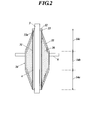
- FIG. 2 is an enlarged longitudinal sectional view of a condenser cone in the same embodiment. Note that, in these drawings, the same reference numerals are given to constituent elements that are basically the same as those of the prior art shown in FIG.
- the lower end of the lead conductor 3 is in the liquid refrigerant layer 5.
- the lead conductor 3 is connected to the conductor 10 of the superconducting cable by a connection terminal 20 such as a flexible connector.
- the lead conductor 3 whose lower end is connected to the conductor 10 has a high voltage lead portion 13 that continues upward from the temperature gradient portion 12 via the cryogenic temperature portion 11, the temperature gradient portion 12, and the flange 6. After that, it is drawn out to the tip of the high voltage lead-out part 13, that is, the room temperature part.
- the cryogenic temperature portion 11 and the temperature gradient portion 12 are covered with an external pressure vessel 21 made of SUS that mainly forms a vacuum heat insulating layer as shown in FIG.
- the liquid refrigerant layer 5 and the refrigerant gas layer 4 are formed in the internal pressure vessel 22.
- the external pressure vessel 21 and the internal pressure vessel 22 constitute a liquid refrigerant vessel 23.
- Reference numeral 5 a denotes the liquid level of the liquid refrigerant layer 5.
- the high voltage lead-out portion 13 partitioned by the temperature gradient portion 12 and the flange 6 is provided mainly at the insulator 1, the oil layer 2 made of insulating oil or the like filled in the insulator 1, and the tip of the insulator 1.
- the high voltage terminal 24 is configured.
- the lead conductor 3 of the present invention arranged in the terminal connection portion of the superconducting cable in this way, the portion protruding into the atmosphere is at room temperature, and the portion located in the internal pressure vessel 22 of the liquid refrigerant vessel 23 is the pole. It is low temperature. Therefore, the lead conductor 3 straddles a portion located in the cryogenic temperature portion 11, a portion located in the temperature gradient portion 12, and a portion located in the high voltage lead portion 13.
- the lead conductor 3 has a structure having an insulator having a capacitor cone structure, which will be described in detail with reference to the longitudinal sectional view of FIG.
- a stainless steel hollow pipe 31 is coaxially arranged on the outer periphery of the lead conductor 3 made of a good conductor such as copper and aluminum with a gap ⁇ .
- the upper end of the hollow pipe 31 is supported by the lead conductor 3 using a flange 32.
- the flange 32 is formed as an annular flange having substantially the same diameter as the outer diameter of the hollow pipe 31, and is fixed to the outer periphery of the lead conductor 3 that penetrates the center portion thereof.
- an annular end plate 33 is integrally formed at the upper end of the hollow pipe 31, and a hole 33 a through which the lead conductor 3 penetrates airtightly is formed at the center of the end plate 33. Then, the end plate 33 is attached to the flange 32, so that the hollow pipe 31 is supported by the lead conductor 3 in a positioned state.
- the hollow pipe 31 does not need to be a metal, and a resin pipe such as FRP (Fiber Reinforced Plastics) can be used. In this case, there is an advantage that heat intrusion from normal temperature can be reduced.
- the distance between the lead conductor 3 and the hollow pipe 31 is preferably 10 mm or more so that the liquid refrigerant can easily enter as a difference between the outer diameter of the lead conductor 3 and the inner diameter of the hollow pipe 31.
- a condenser cone insulator 34 made of FRP as a main insulating material is formed on the outer periphery of the hollow pipe 31.
- the capacitor cone insulator 34 has the same configuration as that of a capacitor cone portion conventionally employed in a terminal connection portion such as an OF cable (oil-filled cable). That is, a metal foil 35 forming a capacitor electrode having a constant width is embedded in the insulator 36 so as to be stepped and concentric at substantially constant intervals in parallel with each other in the spindle-shaped cones 14a and 14c. ing.
- the insulator 36 epoxy resin, EPR (ethylene propylene rubber), rubber, FRP, or the like is used.
- the metal foil 35 is made of aluminum foil or the like, and in the capacitor cone insulator 34, capacitors of the same capacity are connected in series from the high voltage (leading conductor 3) side to the low voltage (flange 6) side.
- the electric field along the interface of the capacitor cone insulator 34 is arranged almost uniformly.
- a ground wire (not shown) to the metal foil 35 which is the outermost layer of the capacitor cone insulator 34 and grounding, the surface electric field of the cylindrical portion 14b having the outermost diameter of the lead conductor 3 is set to the ground potential. Can do.
- a flange 6 is provided in the cylindrical portion 14b, and this is for isolating the oil layer 2 and the refrigerant gas layer 4 in FIG. 1, and an adhesive or the like is applied to the surface of the condenser cone insulator 34. It is fixed so that there is no oil leak or gas leak.
- a capacitor cone insulator using a film was manufactured.
- a polyimide film tape or a polyethylene film tape coated with an adhesive resin, a glass tape impregnated with an epoxy resin in advance, or the like is used.
- these tapes are laminated while being wound, and are adhered while adhering an adhesive and a resin between the films.
- the capacitor cone insulator is formed by winding an aluminum tape after being wound with a thickness of about 1 mm to 2 mm. This method has an advantage that a capacitor cone insulator can be manufactured without using a high-pressure impregnation pot and the manufacturing cost can be reduced.
- the air termination for 275 kV is required to withstand an impulse voltage of 1300 kV, and as a design electric field of the capacitor cone insulator 34 at this time, the creeping strengths in the liquid refrigerant layer 5 and the oil layer 2 are both about 1.3 kV / mm.
- the design allowable electric field of 10 kV / mm it was possible to obtain a terminal with high electrical insulation reliability that does not cause discharge or dielectric breakdown.
- the refrigerant gas layer 4 can also have a length of 1000 mm or more, the heat inflow from the wall surface of the liquefied refrigerant container 22 and the heat inflow from the lead conductor 3 during that period are reduced to 500 W or less, A small terminal connection could be realized.
- the insulator since the insulator is not directly applied to the lead conductor 3 and the interval is maintained, the heat of the lead conductor 3 is not transmitted to the insulator 36, and the temperature of the insulator 36 is short-circuited. There was no temperature rise compared to before. Thereby, the insulator 36 was not cracked or cracked.
- a superconducting cable termination connecting device that can withstand a current test of 3000 A, a voltage of 275 kV, an impulse voltage of 1300 kV, and a short-circuit current of 63 kA can be configured, and a highly reliable termination connection can be provided. it can.
- the superconducting cable was mentioned in a present Example, it has the same function also as a termination
- the voltage gradient portion (cone portions 14a and 14c) of the capacitor cone insulator 34 is immersed in the liquid refrigerant layer 5 and the oil layer 2 so that the withstand voltage is high. Insulation design with a margin can be achieved, and furthermore, by making the surface electric field of the insulator 36 in the refrigerant gas layer 4 with a low withstand voltage low as a ground electric field, there is no discharge or flashover accident in the gas layer with low withstand voltage characteristics. We were able to.
- both the liquid surface 5a of the liquid refrigerant layer 5 and the upper surface of the flange 6 (or the lower end of the oil layer 2) are located within the height range of the cylindrical portion 14b of the condenser cone insulator 34. Furthermore, by providing a gap between the lead conductor 3 and the hollow pipe 31 of the capacitor cone insulator 34, it is difficult for excessive stress to be applied to the insulating coating in the insulating coating portion of the lead conductor 3, and the resin conductor is made of resin. The insulation coating is difficult to break. Therefore, it is possible to provide a highly reliable terminal connection portion for a cryogenic cable.
- the present invention can be used for a terminal structure of a cryogenic cable or a superconducting cable for transmitting electric power.
Landscapes
- Gas Or Oil Filled Cable Accessories (AREA)
- Cable Accessories (AREA)
- Containers, Films, And Cooling For Superconductive Devices (AREA)
Abstract
Description
図1は本発明の実施形態に係る極低温ケーブル、超電導ケーブル等の終端接続部の要部縦断面図であり、図2は同実施形態におけるコンデンサーコーンの拡大縦断面図である。
なお、これらの図において、図3に示す従来技術と基本的に同一の構成要素については同一の符号を付してある。
次に、275kVの超電導ケーブル用に製作した終端接続部を例に、それぞれの効果を併せて説明する。275kV超電導ケーブル用終端接続部の引出し導体3は、引出し導体3としての棒に、銅製の棒を使用した。銅棒の外径は70mmφであった。中空パイプ31には、内径85mmφ、外径105mmφのFRPパイプを使用した。中空パイプ31の外側には、コンデンサーコーン絶縁体34が施され、下部のコーン部14aは長さ1000mm、円柱部14bは長さ1500mm、上部のコーン部14cは1000mmであった。
2 油層
3 引出し導体
4 冷媒ガス層
5 液体冷媒層
10 導体
11 極低温部
12 温度傾斜部
13 高電圧引出部
14a、14c コーン部
14b 円柱部分
20 接続端子
21 外部圧力容器
22 内部圧力容器
23 液体冷媒容器
24 高電圧端子
31 中空パイプ
32 フランジ
33 端板
33a 孔
34 コンデンサーコーン絶縁体
35 金属箔
Claims (6)
- 液体冷媒層、冷媒ガス層及び油層を経て極低温から常温に引き出される引出し導体を有する極低温ケーブルの終端接続部において、
前記引出し導体には、高圧電位から接地電位まで電界を分圧する複数枚の金属箔が絶縁体を介して積層されたコンデンサーコーン絶縁体が施され、
前記高圧電位から接地電位まで順次電圧が変化する電界傾斜部のうち、下部に位置する電界傾斜部が液体冷媒層に、上部に位置する電界傾斜部が油層にあることを特徴とする極低温ケーブルの終端接続部。 - 前記冷媒ガス層のコンデンサーコーン絶縁体の表面の電位が接地電位であり、冷媒ガス層におけるコンデンサーコーン絶縁体の長さが1000mm以上であることを特徴とする請求項1に記載の極低温ケーブルの終端接続部。
- 前記コンデンサーコーン絶縁体が中空パイプの外周に施工されていて、中空パイプ内部に前記引出し導体が常温から極低温部まで貫通していることを特徴とする請求項1又は請求項2に記載の極低温ケーブルの終端接続部。
- 前記引出し導体の外径と前記中空パイプの内径との差が少なくても10mm以上あることを特徴とする請求項3に記載の極低温ケーブルの終端接続部。
- 前記中空パイプの上部は、前記引出し導体との間が気密構造であることを特徴とする請求項3又は請求項4に記載の極低温ケーブルの終端接続部。
- 前記冷媒ガス層と油層の間におけるコンデンサーコーン絶縁体の外周に、前記冷媒ガス層と油層とを気密に区画するフランジが設けられていることを特徴とする請求項1~請求項5の何れかに記載の極低温ケーブルの終端接続部。
Priority Applications (2)
| Application Number | Priority Date | Filing Date | Title |
|---|---|---|---|
| CN201180008315.5A CN102754296B (zh) | 2010-02-04 | 2011-01-31 | 极低温线缆终端连接器 |
| US13/576,689 US9728950B2 (en) | 2010-02-04 | 2011-01-31 | Cryogenic cable termination connector |
Applications Claiming Priority (2)
| Application Number | Priority Date | Filing Date | Title |
|---|---|---|---|
| JP2010-022909 | 2010-02-04 | ||
| JP2010022909A JP5566714B2 (ja) | 2010-02-04 | 2010-02-04 | 極低温ケーブルの終端接続部 |
Publications (1)
| Publication Number | Publication Date |
|---|---|
| WO2011096348A1 true WO2011096348A1 (ja) | 2011-08-11 |
Family
ID=44355346
Family Applications (1)
| Application Number | Title | Priority Date | Filing Date |
|---|---|---|---|
| PCT/JP2011/051860 Ceased WO2011096348A1 (ja) | 2010-02-04 | 2011-01-31 | 極低温ケーブルの終端接続部 |
Country Status (4)
| Country | Link |
|---|---|
| US (1) | US9728950B2 (ja) |
| JP (1) | JP5566714B2 (ja) |
| CN (1) | CN102754296B (ja) |
| WO (1) | WO2011096348A1 (ja) |
Cited By (1)
| Publication number | Priority date | Publication date | Assignee | Title |
|---|---|---|---|---|
| CN104348129A (zh) * | 2013-07-30 | 2015-02-11 | 昭和电线电缆系统株式会社 | 超低温设备的末端装置 |
Families Citing this family (8)
| Publication number | Priority date | Publication date | Assignee | Title |
|---|---|---|---|---|
| JP5628620B2 (ja) * | 2010-10-05 | 2014-11-19 | 公益財団法人鉄道総合技術研究所 | パワーリード及び該パワーリードを備えた送電システム |
| JP5810925B2 (ja) * | 2012-01-10 | 2015-11-11 | 住友電気工業株式会社 | 常温絶縁型超電導ケーブルの接続構造 |
| KR102005583B1 (ko) * | 2013-01-23 | 2019-10-08 | 엘에스전선 주식회사 | 초전도 기기용 종단 구조체 |
| KR102005582B1 (ko) * | 2013-01-23 | 2019-07-30 | 엘에스전선 주식회사 | 초전도 기기용 종단 구조체 |
| JP6140377B2 (ja) * | 2015-02-10 | 2017-05-31 | 古河電気工業株式会社 | 超電導ケーブル及び超電導ケーブルの製造方法 |
| JP2016226143A (ja) * | 2015-05-29 | 2016-12-28 | 昭和電線ケーブルシステム株式会社 | 極低温ケーブルの終端接続部 |
| DE102016220852A1 (de) * | 2016-10-24 | 2018-04-26 | Siemens Aktiengesellschaft | Mobiler Transformatordurchführungsanschluss |
| CN110752575B (zh) * | 2019-09-05 | 2020-12-01 | 国网江苏省电力有限公司电力科学研究院 | 一种三相同轴超导电缆应力锥 |
Citations (4)
| Publication number | Priority date | Publication date | Assignee | Title |
|---|---|---|---|---|
| JPH08196032A (ja) * | 1995-01-13 | 1996-07-30 | Sumitomo Electric Ind Ltd | 極低温ケーブルの端末構造 |
| JP2002280628A (ja) * | 2001-03-16 | 2002-09-27 | Sumitomo Electric Ind Ltd | 極低温機器の端末構造 |
| JP2005117724A (ja) * | 2003-10-03 | 2005-04-28 | Sumitomo Electric Ind Ltd | 超電導ケーブルの端末構造 |
| JP2008507829A (ja) * | 2004-07-28 | 2008-03-13 | アーベーベー・リサーチ・リミテッド | 高電圧ブッシング |
Family Cites Families (12)
| Publication number | Priority date | Publication date | Assignee | Title |
|---|---|---|---|---|
| US3677675A (en) | 1970-01-27 | 1972-07-18 | Koehring Co | Plastics thermoforming machine |
| DE2112406C3 (de) * | 1971-03-15 | 1975-08-28 | Siemens Ag, 1000 Berlin Und 8000 Muenchen | Ausgleichsanordnung für supraleitende Kabel |
| DE2157125C3 (de) * | 1971-11-17 | 1975-07-17 | Siemens Ag, 1000 Berlin Und 8000 Muenchen | Stromzuführung für elektrische Einrichtungen mit auf Tieftemperatur gekühlten Leitern |
| US3801723A (en) * | 1972-02-02 | 1974-04-02 | Fujikura Ltd | Structure of the terminal portion of a cable |
| JPS5825722Y2 (ja) * | 1977-06-21 | 1983-06-02 | 三菱電線工業株式会社 | 極低温ケ−ブルの端末部 |
| JP2001008356A (ja) | 1999-06-15 | 2001-01-12 | Sumitomo Electric Ind Ltd | 絶縁導体 |
| CN100356646C (zh) * | 2001-02-13 | 2007-12-19 | 住友电气工业株式会社 | 低温设备的终端结构 |
| US7192681B2 (en) | 2001-07-05 | 2007-03-20 | Fuji Photo Film Co., Ltd. | Positive photosensitive composition |
| JP2005009582A (ja) * | 2003-06-19 | 2005-01-13 | Sumitomo Electric Ind Ltd | 低温用の締結構造 |
| JP4028454B2 (ja) | 2003-07-11 | 2007-12-26 | 古河電気工業株式会社 | 極低温ケーブルの終端接続部 |
| JP4784852B2 (ja) * | 2005-01-12 | 2011-10-05 | 住友電気工業株式会社 | 超電導機器の低温容器 |
| CA2564235C (en) * | 2005-02-15 | 2012-08-14 | Sumitomo Electric Industries, Ltd. | Terminal structure of superconducting cable |
-
2010
- 2010-02-04 JP JP2010022909A patent/JP5566714B2/ja not_active Expired - Fee Related
-
2011
- 2011-01-31 CN CN201180008315.5A patent/CN102754296B/zh not_active Expired - Fee Related
- 2011-01-31 US US13/576,689 patent/US9728950B2/en not_active Expired - Fee Related
- 2011-01-31 WO PCT/JP2011/051860 patent/WO2011096348A1/ja not_active Ceased
Patent Citations (4)
| Publication number | Priority date | Publication date | Assignee | Title |
|---|---|---|---|---|
| JPH08196032A (ja) * | 1995-01-13 | 1996-07-30 | Sumitomo Electric Ind Ltd | 極低温ケーブルの端末構造 |
| JP2002280628A (ja) * | 2001-03-16 | 2002-09-27 | Sumitomo Electric Ind Ltd | 極低温機器の端末構造 |
| JP2005117724A (ja) * | 2003-10-03 | 2005-04-28 | Sumitomo Electric Ind Ltd | 超電導ケーブルの端末構造 |
| JP2008507829A (ja) * | 2004-07-28 | 2008-03-13 | アーベーベー・リサーチ・リミテッド | 高電圧ブッシング |
Cited By (1)
| Publication number | Priority date | Publication date | Assignee | Title |
|---|---|---|---|---|
| CN104348129A (zh) * | 2013-07-30 | 2015-02-11 | 昭和电线电缆系统株式会社 | 超低温设备的末端装置 |
Also Published As
| Publication number | Publication date |
|---|---|
| US9728950B2 (en) | 2017-08-08 |
| US20130059463A1 (en) | 2013-03-07 |
| CN102754296B (zh) | 2016-10-26 |
| JP5566714B2 (ja) | 2014-08-06 |
| JP2011160641A (ja) | 2011-08-18 |
| CN102754296A (zh) | 2012-10-24 |
Similar Documents
| Publication | Publication Date | Title |
|---|---|---|
| JP5566714B2 (ja) | 極低温ケーブルの終端接続部 | |
| US20120092115A1 (en) | Current transformer | |
| WO2002065605A1 (en) | Terminal structure of extreme-low temperature equipment | |
| CN102884693B (zh) | 极低温电缆用终端连接部 | |
| US8633381B2 (en) | Termination unit for multi-phase superconductor cable | |
| JP2009534787A (ja) | 細長部材及びその使用 | |
| WO2011152342A1 (ja) | 超電導ケーブル導体の端末構造およびその端子部材 | |
| CN102057447A (zh) | 具有基础有源部件和绝缘装置的绝缘套管 | |
| CN103247995A (zh) | 超低温设备的终端装置 | |
| CN1967955B (zh) | 气体绝缘开关装置与油浸变压器的连接结构 | |
| JP6352782B2 (ja) | 絶縁スペーサ | |
| CN100449653C (zh) | 带衬层的高压绝缘芯体 | |
| US3049581A (en) | Sealing ends for high tension electric cables | |
| CN104160458A (zh) | 用于高压直流电和超高压的插头插座式的纯气体绝缘穿壁套管 | |
| PL242486B1 (pl) | Piorunochron z odizolowaną od chronionego obiektu instalacją odgromową, z zespołem zasilająco-sterującym i monitorującym stan techniczny jego głowicy | |
| KR20160128655A (ko) | 초전도 기기용 접속함 | |
| US20190318873A1 (en) | Adaptor for a capacitor | |
| CN204167834U (zh) | 一种高压穿墙套管的户外部分 | |
| JP5395038B2 (ja) | ガス絶縁電気機器 | |
| Euvrard et al. | Advances in High Voltage Outdoor Dry Type Cable Terminations: An Easy to Install Cable Termination Design that Combines Capacitive Graded Stress Control with a Robust Self-Supporting Termination Body | |
| JP5742006B2 (ja) | 常温絶縁型超電導ケーブルの端末構造 | |
| KR20180036773A (ko) | Hvdc mi 케이블의 금속성 시스를 전기적으로 분리시키는 방법 | |
| KR20110005537A (ko) | 코팅된 도전봉이 내설된 종단 접속함용 초전도 케이블의 단말구조체 | |
| JP5734748B2 (ja) | 受電点ブッシング | |
| RU2319242C1 (ru) | Опорный полимерный изолятор повышенной надежности |
Legal Events
| Date | Code | Title | Description |
|---|---|---|---|
| WWE | Wipo information: entry into national phase |
Ref document number: 201180008315.5 Country of ref document: CN |
|
| 121 | Ep: the epo has been informed by wipo that ep was designated in this application |
Ref document number: 11739696 Country of ref document: EP Kind code of ref document: A1 |
|
| WWE | Wipo information: entry into national phase |
Ref document number: 13576689 Country of ref document: US |
|
| NENP | Non-entry into the national phase |
Ref country code: DE |
|
| 122 | Ep: pct application non-entry in european phase |
Ref document number: 11739696 Country of ref document: EP Kind code of ref document: A1 |