WO2011083704A1 - Mobility management device, multicast service delivery device, mobile communication system, mobile station device, and mobile communication method - Google Patents
Mobility management device, multicast service delivery device, mobile communication system, mobile station device, and mobile communication method Download PDFInfo
- Publication number
- WO2011083704A1 WO2011083704A1 PCT/JP2010/073344 JP2010073344W WO2011083704A1 WO 2011083704 A1 WO2011083704 A1 WO 2011083704A1 JP 2010073344 W JP2010073344 W JP 2010073344W WO 2011083704 A1 WO2011083704 A1 WO 2011083704A1
- Authority
- WO
- WIPO (PCT)
- Prior art keywords
- multicast
- service area
- base station
- start request
- session start
- Prior art date
Links
Images


Classifications
-
- H—ELECTRICITY
- H04—ELECTRIC COMMUNICATION TECHNIQUE
- H04W—WIRELESS COMMUNICATION NETWORKS
- H04W40/00—Communication routing or communication path finding
-
- H—ELECTRICITY
- H04—ELECTRIC COMMUNICATION TECHNIQUE
- H04L—TRANSMISSION OF DIGITAL INFORMATION, e.g. TELEGRAPHIC COMMUNICATION
- H04L12/00—Data switching networks
- H04L12/02—Details
- H04L12/16—Arrangements for providing special services to substations
- H04L12/18—Arrangements for providing special services to substations for broadcast or conference, e.g. multicast
- H04L12/185—Arrangements for providing special services to substations for broadcast or conference, e.g. multicast with management of multicast group membership
-
- H—ELECTRICITY
- H04—ELECTRIC COMMUNICATION TECHNIQUE
- H04L—TRANSMISSION OF DIGITAL INFORMATION, e.g. TELEGRAPHIC COMMUNICATION
- H04L12/00—Data switching networks
- H04L12/02—Details
- H04L12/16—Arrangements for providing special services to substations
- H04L12/18—Arrangements for providing special services to substations for broadcast or conference, e.g. multicast
- H04L12/1886—Arrangements for providing special services to substations for broadcast or conference, e.g. multicast with traffic restrictions for efficiency improvement, e.g. involving subnets or subdomains
-
- H—ELECTRICITY
- H04—ELECTRIC COMMUNICATION TECHNIQUE
- H04L—TRANSMISSION OF DIGITAL INFORMATION, e.g. TELEGRAPHIC COMMUNICATION
- H04L12/00—Data switching networks
- H04L12/02—Details
- H04L12/16—Arrangements for providing special services to substations
- H04L12/18—Arrangements for providing special services to substations for broadcast or conference, e.g. multicast
- H04L12/189—Arrangements for providing special services to substations for broadcast or conference, e.g. multicast in combination with wireless systems
-
- H—ELECTRICITY
- H04—ELECTRIC COMMUNICATION TECHNIQUE
- H04W—WIRELESS COMMUNICATION NETWORKS
- H04W72/00—Local resource management
- H04W72/30—Resource management for broadcast services
-
- H—ELECTRICITY
- H04—ELECTRIC COMMUNICATION TECHNIQUE
- H04L—TRANSMISSION OF DIGITAL INFORMATION, e.g. TELEGRAPHIC COMMUNICATION
- H04L45/00—Routing or path finding of packets in data switching networks
- H04L45/16—Multipoint routing
-
- H—ELECTRICITY
- H04—ELECTRIC COMMUNICATION TECHNIQUE
- H04W—WIRELESS COMMUNICATION NETWORKS
- H04W4/00—Services specially adapted for wireless communication networks; Facilities therefor
- H04W4/06—Selective distribution of broadcast services, e.g. multimedia broadcast multicast service [MBMS]; Services to user groups; One-way selective calling services
Definitions
- the present invention relates to a mobile communication system and the like.
- MBMS Multimedia Broadcast / Multicast Service
- EPS Evolved Packet System
- an MBMS service area is defined as a range for performing a certain MBMS session.
- a service area is set in units of regions such as nationwide and Kanto, and is configured by a plurality of cells in the service area.
- a multicast data distribution route (hereinafter referred to as a multicast distribution route) is set in EPC (Evolved Packet Core) constituting the EPS and in a radio access network such as E-UTRAN or UTRAN connected to the EPC,
- EPC Evolved Packet Core
- a base station eNodeB in E-UTRAN
- RNC radio network control station
- a bearer is a logical transmission path.
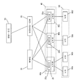
- FIG. 18 shows a conceptual diagram of conventional multicast data distribution. Arrows indicate the flow of multicast data.
- the data transmitted from the content server is transmitted to the lower nodes GW2 and GW3 with GW1 as a branch point, and further transmitted to the base stations 1 to 6 of the cells 1 to 6 in the service area.
- a multicast distribution route is set in a tree shape from the content server to the base station via the GW.
- the terminals are located in the cells 1 to 6 in the service area and receive the multicast data.
- Such conventional multicast data distribution distributes multicast data not in units of cells but in units of service areas (MBMS service areas defined in Non-Patent Document 1). For this reason, even if there is a cell in the service area where a terminal to be distributed is not located, the data is distributed to the base station of the cell at the start of the distribution of the multicast data.
- the receiving terminals are distributed over a wide geographical area, and as a result, there is a probability that none of the cells constituting the service area are in the cell. Is relatively low, and delivering data to the base station of the cell has not been a problem.
- Non-Patent Document 2 lists use cases such as a guided tour of travel.
- a multicast service for customers at a customer collection facility such as a sports or concert venue or a shopping center can be considered.
- a customer collection facility such as a sports or concert venue or a shopping center
- the distribution range is limited according to the service to be provided, and the terminals are also unevenly distributed. Furthermore, the location and time of the service to be provided are dynamically set and cannot be determined in advance.
- the conventional mobile communication system described above is based on the premise that the MBMS service area is geographically wide, and a new multicast service form as described in Non-Patent Document 2 (within a limited geographical range). Multicast data is distributed to all base stations that make up a wide range of MBMS service areas, even in the case where a multicast service for users) is realized. There is a possibility that data may be distributed, resulting in an increase in useless resources.
- a limited narrow MBMS service area may be individually set.
- settings related to the MBMS service area for example, a list of base stations constituting the MBMS service area
- the location and time cannot be specified in advance as in the new multicast service described above, it will be linked to the location of the terminal when the service starts. It was impossible to select cells and configure service areas.
- the base station sets radio resources for data distribution Whether or not to do so is controlled at the level of the radio access network, and since nodes in the core network (EPC) are not involved, a multicast distribution route is set up at least to the base station, and the inefficiency of network resources is There was no way to solve it.
- EPC core network
- the present invention aims to perform efficient communication without using wasteful resources by distributing multicast data only to base stations where mobile terminals are located. It is to provide a mobile communication system and the like that can perform the above.
- the mobility management device of the present invention provides: A service area is composed of a plurality of cells in which base station devices are arranged, and a multicast station is located in the service area by transmitting multicast data from the multicast service distribution device to the base station device in the service area.
- a mobility management device connected to a mobile communication system that provides a multicast service to a device to manage the mobile station device, Terminal management means for managing the mobile station device in association with the base station device in which the mobile station device is located; Start request receiving means for receiving a multicast session start request from the multicast service distribution device; When a dynamic service area configuration identifier is included in the session start request, a cell in which a base station apparatus where the mobile station apparatus is located is assigned as a dynamic service area from the terminal management means.
- Service area determination means for determining; First session start request transmission means for transmitting a session start request to a base station apparatus included in the service area determined by the service area determination means; It is characterized by providing.
- the mobility management device of the present invention Further comprising participation request receiving means for receiving a request to join a multicast group from the mobile station device;
- the terminal management means manages the identifier of the multicast group, the mobile station apparatus, and the base station apparatus in which the mobile station apparatus is located in association with each other,
- the service area determination unit includes a base station associated with the multicast group corresponding to the session start request from the terminal management unit.
- the cell in which the device is arranged is determined as a dynamic service area.
- a base station adjustment device that manages the base station device and adjusts between the base station devices is further connected to the mobile communication system,
- the first session start request transmission unit transmits a session start request including information related to the base station device to a base station adjustment device that manages the base station device included in the service area determined by the service area determination unit. It is characterized by doing.
- a service area is configured from a plurality of cells in which base station devices are arranged, and multicast data is transmitted from the multicast service distribution device to the base station device in the service area,
- a multicast service distribution apparatus connected to a mobile communication system that provides a multicast service to a mobile station apparatus located in the service area,
- a second session start request transmitting means for transmitting a session start request to a mobility management apparatus connected to manage the mobile station apparatus at the start of a multicast session;
- the second session start request transmission means wants the mobility management apparatus to dynamically configure a base station apparatus arranged in a cell where the mobile station is located as a service area
- the session start request Includes a dynamic service area configuration identifier.
- the mobile communication system of the present invention is A service area is composed of a plurality of cells in which base station devices are arranged, and a multicast station is located in the service area by transmitting multicast data from the multicast service distribution device to the base station device in the service area.
- a cell in which a base station device in which the mobile station device is located is dynamically configured as a service area.
- the mobile communication system of the present invention includes a mobility management device that manages mobile station devices, The mobility management device, together with the mobile station device, manages the base station device in which the mobile station device is located, and when receiving an instruction from the multicast service distribution device to configure a dynamic service area, A base station apparatus in which the mobile station apparatus is located is selected, and a communication path is set with the base station apparatus.
- the mobile communication system of the present invention is A service area is composed of a plurality of cells in which base station devices are arranged, and a multicast station is located in the service area by transmitting multicast data from the multicast service distribution device to the base station device in the service area.
- the mobility management device Terminal management means for managing the mobile station device in association with the base station device in which the mobile station device is located;
- Start request receiving means for receiving a multicast session start request from the multicast service distribution device;
- a dynamic service area configuration identifier is included in the session start request, a cell in which a base station apparatus where the mobile station apparatus is located is assigned as a dynamic service area from the terminal management means.
- Service area determination means for determining;
- First session start request transmission means for transmitting a session start request to a base station apparatus included in the service area determined by the service area determination means; It is characterized by providing.
- the mobile station apparatus of the present invention is a mobile station apparatus connected to the mobile communication system described above, Multicast bearer setting means for setting a multicast bearer with the base station device; Multicast data receiving means for receiving multicast data from the multicast service delivery device using the multicast bearer; It is characterized by providing.
- a service area is composed of a plurality of cells in which base station devices are arranged, and a multicast station is located in the service area by transmitting multicast data from the multicast service distribution device to the base station device in the service area.
- a mobile communication method in a mobile communication system for providing a multicast service to an apparatus A cell in which a base station device in which the mobile station device is located is dynamically configured as a service area.
- a service area is composed of a plurality of cells in which base station devices are arranged, and a multicast station is located in the service area by transmitting multicast data from the multicast service distribution device to the base station device in the service area.
- a mobile communication method in a mobile communication system for providing a multicast service to an apparatus Associating and managing the mobile station device and a base station device in which the mobile station device is located; Receiving a multicast session start request from the multicast service distribution device; and When a dynamic service area configuration identifier is included in the session start request, a cell in which a base station apparatus where the mobile station apparatus is located is assigned as a dynamic service area from the terminal management means.
- the conventional multicast data distribution destination cell is not selected by the mobility management device, and the multicast distribution route is set for all the base station devices in the mobile communication system managed by the mobility management device.
- the mobility management device dynamically selects a delivery destination base station device according to the cell in which the mobile station device is located, so that only the selected base station device participates in the delivery route and sets an extra delivery route. This eliminates the need for network resources and wireless resources.
- the session start request message is transmitted to all base stations. Since it is not necessary to distribute it to the apparatus, signaling traffic can be suppressed to a low level.
- information related to the mobile station device managed by the multicast service distribution device and the mobility management device of the present invention includes information notified from the mobile station device in the conventional attach or location registration phase and the phase of joining the multicast group.
- the multicast service can be provided without adding a processing load such as causing the mobile station apparatus to notify the new information.
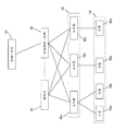
- FIG. 1 is a diagram illustrating a system configuration of a mobile communication system 1 to which the present invention is applied in the first embodiment, and includes a BM-SC 10 (Broadcast-Multicast Service Center), an MBMS-GW 20, and an MME 30.
- the radio access network includes a network, eNB 40 (eNB 40a, eNB 40b, eNB 40c), and UE 50 (UE 50a, UE 50b, UE 50c, UE 50d).
- the BM-SC 10 is an apparatus (multicast service distribution apparatus) that controls distribution of multicast service, and is connected to the MBMS-GW 20 that is an edge node of the core network.
- the MBMS-GW 20 is connected to the eNB 40 and the MME 30 that controls the eNB 40 regarding multicast bearer settings and the like.
- the MME 30 is also connected to the eNB 40.
- the MME 30 is a mobility management device for managing mobile stations, and performs, for example, location management, handover control, and the like.
- eNB40 is a base station (apparatus), and eNB40a, eNB40b, and eNB40c are contained in FIG.
- UE50 is connected as a mobile station (terminal) apparatus which is a user terminal under the control of eNB40.
- terminal mobile station
- UE50a and UE50b are connected to eNB40a
- UE50c is connected to eNB40b
- UE50d is connected to eNB40c, respectively.
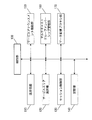
- the BM-SC 10 includes a control unit 100, a transmission / reception unit 110, a service area selection unit 120, a session control unit 130, a storage unit 140, a service announcement function unit 150, a multicast group. Membership management unit 160 and data distribution proxy unit 170 are connected via a bus.
- the control unit 100 is a functional unit that controls the operation of the BM-SC 10, and is composed of, for example, a CPU.
- the control unit 100 implements various functions by reading and executing various programs stored in the storage unit 140.
- the transmission / reception unit 110 is a functional unit for transmitting and receiving data from other nodes and terminals, and is a functional unit for controlling communication.
- the control unit 100 transmits data received by the transmission / reception unit 110 to each functional unit, and data transmitted from each functional unit is transmitted to other nodes and terminals via the transmission / reception unit 110.
- the service area selection unit 120 holds information on one or a plurality of MBMS service areas fixedly determined in advance and selects which MBMS service area to distribute when starting a multicast session. It is a functional unit for causing the lower node to identify the MBMS service area by the identifier (SAI).
- SAI identifier
- the service area selection unit 120 can specify a region or the like that the content provider wants to distribute. For example, when the content provider designates distribution to the entire coverage area of the network provided by the mobile carrier, the service area selection unit 120 selects SAI-0 (meaning all networks) and notifies the lower node. To do.
- SAI-0 meaning all networks
- the SAI is interpreted as an identifier indicating a set of cells in the eNB 40 or the like of the radio access network, and identifies which cell is included in the MBMS service area.
- a means is provided for the BM-SC 10 to instruct it and to make the lower node identify it.
- the service area selection unit 120 is selectable.
- a service area configured by dynamically selecting a multicast delivery destination cell is referred to as a “dynamic service area” for the sake of convenience in order to distinguish it from a fixed MBMS service area.
- dynamic service area configuration identifier an identifier different from the SAI indicating the fixed MBMS service area (hereinafter referred to as “dynamic service area configuration identifier”) may be used, or a certain SAI itself may be configured of the dynamic service area. May be a special SAI having a meaning for the lower node to judge (for example, SAI-0 indicates the entire area covered by the network, and SAI-n indicates that a dynamic service area is configured. means).
- the service area selection unit 120 may interpret that the lower node configures the dynamic service area by not deliberately specifying the SAI as the lower node. Regardless of which method is used, the service area selection unit 120 instructs the configuration of the dynamic service area using any method.
- the BM-SC 10 manages attribute information related to content (start time, end time, genre, etc.) and an IP multicast address in association with each other, and similarly uses a dynamic service area or an MBMS service area. Information is also managed in association with the IP multicast address. Which service area the BM-SC 10 selects may be based on information acquired from a content provider before starting a multicast service session (hereinafter referred to as a multicast session), or based on content attribute information. You may judge.
- the session control unit 130 is a functional unit for controlling a multicast session.
- the session control unit 130 allocates a unique identifier (TMGI: Temporary Mobile Group Identity) for each multicast group of a plurality of UEs 50 participating in a single multicast session.
- TMGI Temporary Mobile Group Identity
- the storage unit 140 is a functional unit for storing various programs and data necessary for the operation of the BM-SC 10.
- the control unit 100 and other functional units realize the functions by reading out programs and data from the storage unit 140 and executing processes as necessary.
- the storage unit 140 is configured by a storage device such as a semiconductor memory such as an EEPROM or a DRAM, or a magnetic disk such as an HDD.
- the service announcement function unit 150 is a function unit for announcing information (start time, end time, description of contents, etc.) related to the service to the UE 50 possessed by the user.
- the multicast group membership management unit 160 is a functional unit for permitting the UE 50 that desires reception to participate in the multicast group and managing it as a multicast group.
- the data distribution proxy unit 170 is a functional unit used when distributing data to lower nodes.
- the MME 30 includes a transmission / reception unit 310, a UE location management unit 320, an attach / location registration reception unit 330, a storage unit 340, a multicast control signal reception unit 350, and a multicast bearer setting instruction transmission unit 360.
- the dynamic service area configuration determination unit 370 and the multicast UE management unit 380 are connected.
- the control unit 300 is a functional unit that controls the operation of the MME 30, and includes, for example, a CPU.
- the control unit 300 implements various functions by reading and executing various programs stored in the storage unit 340.
- the transmission / reception unit 310 is a functional unit for transmitting and receiving data from other nodes and terminals, and is a functional unit for controlling communication.
- the control unit 300 transmits data received by the transmission / reception unit 310 to each functional unit, and data transmitted from each functional unit is transmitted to other nodes and terminals via the transmission / reception unit 310.
- the UE location management unit 320 is a functional unit that stores the identifier of the UE 50 that has been in the cell and has performed attachment or location registration together with the cell identifier in location management information 344 described later.
- the attach / location registration receiving unit 330 is a functional unit that receives an attach or location registration control signal from the UE 50.
- the storage unit 340 is a functional unit for storing various programs and data necessary for the operation of the MME 30.
- the control unit 300 and other functional units realize each function by reading out programs and data from the storage unit 340 and executing processes as necessary.
- the storage unit 340 is configured by a storage device such as a semiconductor memory such as an EEPROM or a DRAM, or a magnetic disk such as an HDD.
- the storage unit 340 stores eNB information 342, location management information 344, and UE management information 346.
- the eNB information 342 is information on the identifier and address of the eNB 40 connected to the own station and the identifier of the cell covered by each eNB 40.
- the location management information 344 is information for managing the location of the UE 50 by the UE location management unit 320.
- the UE 50 transmits an attach signal or a location registration signal to the MME 30 when located in the cell.
- the UE 50 identifier IMSI (International Mobile Subscriber Identity) and the cell identifier of the cell where the UE 50 is located (Cell ID) ) In the location registration signal and transmitted to the MME 30.
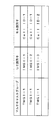
- the UE identifier (eg, “IMSI-1”) and the cell identifier (eg, “Cell ID-1”) are associated with each other. An example of the data structure in this case is shown in FIG.
- the UE 50a has an identifier of “IMSI-1”, and information is configured as being located in a cell identified as “Cell ID-1”.
- the UE 50b (IMSI-2) that has performed attachment or location registration is configured to be located in the same cell “Cell ID-1” as the UE 50a
- the UE 50c (IMSI-3) The information is configured as being located in the cell of “ID-2”.
- the location management information 344 stored based on this attachment or location registration is not limited to performing multicasting, but is information that is constantly updated when the UE 50 is in the cell.
- the UE management information 346 is information managed by the multicast UE management unit 380. Details will be described later.
- a multicast control signal reception unit 350 and a multicast bearer setting instruction transmission unit 360 are provided.
- the multicast control signal receiving unit 350 is a functional unit for inquiring the identifier, address, etc. of the eNB 40 managed by the MME 30 to the storage unit when receiving a control signal related to multicast bearer setting from the MBMS-GW 20 which is a higher node.
- the multicast bearer setting instruction transmission unit 360 is a functional unit for instructing the eNB 40 to set or release a multicast bearer based on the identifier and address of the eNB 40.
- the dynamic service area configuration determining unit 370 is a functional unit for determining that a dynamic service area is configured instead of setting a delivery route in a fixed MBMS service area for a certain multicast session.
- FIG. 5 shows information included in the session start request message that the MME 30 receives from the upper node when starting a certain multicast session.
- the session start request message usually has a message field including an IP multicast address, a multicast group identifier TMGI, and a service area identifier SAI.
- SAI is an identifier indicating a conventional fixed service area, and is included for identifying the eNB 40 included in the MBMS service area at the level of the radio access network.
- the MME 30 can determine whether to dynamically configure the service area.
- the dynamic service area configuration identifier is added to the message field when the BM-SC 10 transmits a session start request message.
- a dynamic service area identifier (specifier)
- SAI a method for enabling the MME 30 to determine the dynamic service area configuration, as described above
- SAI a kind of conventional service area identifier
- the service area identifier is SAI-n
- the content of the message field of the service area identifier is SAI-n.
- the BM-SC 10 transmits the field with the service area identifier field empty. To do.
- the multicast UE management unit 380 is a functional unit for managing and updating the UE 50 that participates in the multicast group based on the multicast group participation request message from the UE 50.
- UE management information (correspondence table) managed by the multicast UE management unit 380 will be described using FIG. 6 as an example.
- the multicast group is identified by TMGI at each node. Therefore, in the multicast UE management unit 380, for example, when the UE 50a participates in the multicast group “TMGI-1”, the UE management in which “IMSI-1” that is the identifier of the UE 50a is associated with “TMGI-1”.
- Information 346 is stored in multicast UE management section 380.
- the multicast UE management unit 380 stores the UE management information 346 further associated with the identifier “Cell ID-1” of the cell in which the UE 50 a is located.
- the UE management information 346 is information for operating the multicast distribution method according to the present embodiment.
- the multicast UE management unit 380 is in a phase in which the UE 50 requests to join the multicast group.
- the information regarding the UE 50 managed in each configuration of the BM-SC 10 and the MME 30 described above is notified to the BM-SC 10 and the MME 30 from the UE 50 in the attach or location registration phase and the phase of joining the multicast group as usual.
- the UE 50 does not require any functional change from the conventional configuration.
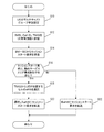
- step S10 when the UE 50 is set to participate in the multicast group (step S10), the UE management information 346 that associates the identifier IMSI of the UE 50, the identifier Cell ID of the existing cell, and the identifier TMGI of the multicast group is obtained.
- step S12 when there are other UEs 50 requesting participation in the multicast group, step S12 is similarly performed.
- the MME 30 receives a session start request message transmitted from the BM-SC 10 (step S14).
- This session start request message includes TMGI.
- step S16 it is determined whether or not to configure a dynamic service area based on whether or not the dynamic service area configuration identifier is included in the session start request message. If it is included, it is determined that a dynamic service area is configured, and the Cell ID of the serving cell of UE 50 associated with the TMGI of the multicast group is read from UE management information 346, and the cell is The eNB 40 to be covered is selected (Step S16; Yes ⁇ Step S18). Then, a session start request message is transmitted to the selected eNB 40 (step S20).
- step S16 when the dynamic service area configuration identifier is not included in the session start request message in step S16, it is determined that the dynamic service area is not configured, and the multicast operation for the conventional fixed MBMS service area is determined. Then, a session start request message is transmitted to all the eNBs 40 under the MME 30 (Step S16; No ⁇ Step S22).
- the session start request message is transmitted only to the eNB 40 selected by the MME 30 in the processing after step S18, only the eNB 40 of the cell where the UE 50 is located performs the IP multicast participation processing (processing to participate in the multicast tree). As a result, only the necessary eNB 40 participates in the multicast distribution route. That is, a dynamic service area is configured.
- step S16 if it is determined in step S16 that the dynamic service area configuration identifier is not included and the dynamic service area is not configured, it is statically set in advance regardless of whether or not the UE 50 exists. In accordance with the determined MBMS service area, all eNBs 40 that constitute the MBMS service area under the MME 30 participate in the distribution route.
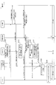
- FIG. 8 is a diagram for explaining an operation example of the entire mobile communication system according to the present embodiment. Each arrow indicates a necessary information flow between the nodes, and a rounded rectangle indicates a process inside the node. Yes.
- the MME 30 stores the IMSI of the UE 50 and the Cell ID of the cell in the location management information 344 by attaching or registering the location from the UE 50 in advance. (S100). At this time, a default bearer is set between the UE 50 and the S-GW (Serving GW), and the MME 30 stores the bearer ID of the default bearer.
- the bearer ID is a unique ID for each UE 50 for which a default bearer is set, and the MME 30 can identify the address of the UE 50 that is the bearer end point.
- the S-GW is a node arranged in the core network, and is an S-GW set as a default router of the UE 50.
- this S-GW may be functionally integrated with the MBMS-GW 20, it is not shown in the system configuration of FIG. 1, but here the operation of the S-GW as the default router and the MBMS-GW 20 In order to distinguish and clarify the operation of, it is described separately.
- S102 to S114 are operations for joining the multicast group of a certain multicast service by the UE 50.
- the UE 50 has acquired the IP multicast address of the multicast service to be received by the prior service announcement, and by specifying it, transmits a multicast group join request to the S-GW in which the default bearer is set (S102). ).
- the S-GW transmits a UE permission request to the BM-SC 10 (S104).
- the BM-SC 10 permits the UE 50
- the identifier TMGI of the multicast group in which the UE participates is granted to the S-GW. Notification is included in the response (S106).
- the S-GW notifies the TMGI to the MME 30 (S108), and the MME 30 stores the UE management information 346 including the TMGI, the IMSI of the UE 50, and the cell ID of the cell in the area (S112).
- the IMSI of the UE 50 that the MME 30 stores as the location management information 344 in S100
- the UE 50 does not directly notify the IMSI, and the TMSI (Temporary Mobile Subscriber Even when notified from the UE 50 in a format such as Identity: an identifier that the MME assigns to the UE temporarily for location management), the IMSI can be specified in a node of the core network such as the BM-SC 10, the S-GW, and the MME 30.
- the IMSI Temporal Mobile Subscriber Even when notified from the UE 50 in a format such as Identity: an identifier that the MME assigns to the UE temporarily for location management
- the IMSI can be specified in a node of the core network such as the BM-SC 10, the S-GW, and the MME 30.
- the MME 30 can specify the IMSI by notifying the bearer ID from the S-GW to the MME 30 in S108.
- the present embodiment is not limited to any one of the methods, and any method may be used as long as the MME 30 can specify the IMSI in the step of S112. Since the IMSI is specified by any one of these methods, the MME 30 can also specify the Cell ID from the location management information 344 previously managed.
- the Cell ID managed by the MME 30 with the UE management information 346 based on the location management information 344 is the identifier of the cell when the UE 50 has recently attached or registered the location, but the MME 30 does not exist in the eNB of the cell.
- a step of inquiring the service area and updating the Cell ID to the latest one can be added (S110).
- the MME 30 may make an inquiry only to the eNB 40 of the cell, or the MME 30 may make an inquiry to each eNB of the cell belonging to the range of the tracking area managed for the purpose of paging to the UE 50 as well as the multicast service. .
- the MME 30 transmits a multicast group join response to the UE 50 (S114). Transmission to the UE 50 is performed based on the bearer ID of the default bearer.
- the operations from S102 to S114 are similarly executed for the second and third UEs 50. Further, the UE 50 can participate in the multicast group even after the multicast session described later is started.
- S116 to S128 are operations when starting a multicast session.
- the BM-SC 10 transmits a session start request including the TMGI and the dynamic service area configuration identifier to the MBMS-GW 20 (S116).
- the MBMS-GW 20 transmits a session start request to the MME 30 (S118).
- the MME 30 reads the dynamic service area configuration identifier from the session start request and determines to configure the dynamic service area (S120). Then, based on the UE management information 346 stored in S112, the Cell ID associated with the TMGI is read and specified, and the eNB 40 of the cell is selected (S122).
- the MME 30 transmits a session start request to the selected eNB 40 (S124).
- information indicating that the multicast service is configured as a dynamic service area may be included in the session start request message.
- the eNB 40 that has received the session start request executes IP multicast participation processing (S126). And eNB40 performs a multicast bearer setting process between UE50, and sets a multicast bearer (S128).
- IP multicast participation processing S126
- eNB40 performs a multicast bearer setting process between UE50, and sets a multicast bearer (S128).
- the MME 30 transmits the session start request to all lower eNBs 40 as in the conventional case, and the eNB 40 Execute the participation process.
- the operation of each eNB 40 is the same as S124, S126, and S128 described above.
- the MME 30 specifies the cell where the UE 50 is located based on the TMGI.
- the UE management information 346 stored in the MME 30 of the present embodiment corresponds to the TMGI, the IMSI, and the Cell ID. Therefore, it is possible to identify the cell ID of the cell in the UE 50 from the IMSI as well as from the TMGI.
- the MME 30 identifies the Cell ID by referring to the UE management information 346 from the IMSI in S120. Will be.
- the BM-SC 10 transmits the session start request in S116 including the MBMS service area identifier (SAI) in addition to the dynamic service area configuration identifier.
- SAI MBMS service area identifier
- the MME 30 dynamically configures the service area by a method in which the SAI itself is a specific SAI or a method in which the SAI is not included in the session start request message. It is good also as judging.
- sequence and processing are not necessarily limited to those shown in FIGS. 9 and 10, and the sequence order and processing may be changed due to specification changes or expansions, or a sequence different from the specifications may be adopted due to system implementation. Even if it is done, the information element in FIG. 8 only needs to be applied to any message or processing operation.
- FIG. 9 and FIG. 10 show the procedure when MBMS processing based on the current GPRS (General Packet Radio Service) is applied to EPS. Even if the message name, message structure, and processing are partially changed, it can be applied.
- EPS can operate in two ways: GPRS extension method and proxy mobile IP method, and FIG. 9 and FIG. 10 describe the case of the proxy mobile IP method, but this also applies to the GPRS extension method. Is possible.
- the UE 50 When the UE 50 transmits an IGMP (IPv4) or MLD (IPv6) Join message, the message reaches the S-GW, which is the default router, using the established communication path (S200). In this case, the UE 50 transmits the IP multicast address of the multicast service desired to be received.
- IGMP IPv4
- MLD IPv6
- the default router of the UE is the P-GW. Therefore, after the message arrives at the P-GW, the P-GW is sent to the S-GW from the UE 50 to the IGMP or MLD Join. The fact that the message has been received and the IP multicast address that the UE 50 desires to receive are notified.
- the S-GW transmits an MBMS permission request message to the BM-SC 10 (S202).
- the BM-SC 10 When the BM-SC 10 permits the UE 50, it notifies the S-GW of the access point name (APN) of the MBMS-GW 20 for setting the multicast bearer as an MBMS permission response (S204). At this time, similarly to S106 in FIG. 8, if the TMGI of the multicast group can be notified, the notification is included in the permission response message. If notification is not possible, information corresponding to S204 is notified in S218 or S222 described later.
- the APN is an identifier for uniquely identifying the gateway (MBMS-GW 20) with the BM-SC 10.
- the S-GW transmits an MBMS notification request message including the IP multicast address, the APN of the MBMS-GW 20, the bearer ID, etc. to the MME 30 (S206). At this time, similarly to S108 in FIG. 8, notification is made including TMGI of the multicast group. If TMGI cannot be notified in this step, transmission is performed in S224 described later.
- the MME 30 can store the IMSI, Cell ID, and TMGI information corresponding to the operation of S112 in FIG. 8, but if TMGI is notified in a later procedure, it will be described later.
- S224 an operation corresponding to the step of S112 is executed.
- the MME 30 transmits an MBMS notification response message to the S-GW (S208). Then, the MME 30 transmits an MBMS context activation start request message to the UE 50 (S210). The UE 50 transmits an MBMS context activation request message to the MME 30 (S212). At this time, it is preferable that the UE 50 notifies the MME 30 of the cell ID of the serving cell, but if not notified, the cell ID is updated by a message corresponding to S110.
- the MME 30 specifies the MBMS-GW 20 from the APN, and transmits an MBMS context generation request message to the MBMS-GW 20 (S214).
- the MBMS-GW 20 transmits an MBMS context generation request message to the BM-SC 10 (S216).
- the BM-SC 10 transmits an MBMS context generation response message to the MBMS-GW 20 (S218). If TMGI is not transmitted in S204, the BM-SC 10 notifies TMGI in the message in S218.
- the MBMS registration request message is further transmitted to the BM-SC 10 (S220). Also, if the TMGI is not yet assigned, for example, because the UE 50 is the first UE that has joined the multicast group, the BM-SC 10 assigns the TMGI to the multicast group and sends it to the MBMS-GW 20. The notification is included in the MBMS registration response message (S222). If the MBMS-GW 20 has information related to the setting of the multicast bearer, or if TMGI has already been assigned and notified, the steps S220 and S222 can be omitted.
- the MBMS-GW 20 transmits an MBMS context generation response message to the MME 30 (S224).
- S224 MBMS context generation response message
- the MME 30 stores the UE management information of the IMSI, TMGI, and Cell ID after this procedure.
- the MME 30 When the eNB 40 has set the radio bearer in the UE 50, the MME 30 notifies the eNB 40 of the MBMS context that is information related to the MBMS bearer setting (S226). The MME 30 transmits an MBMS context activation response message to the UE 50 (S228). This completes the participation procedure of the UE 50 in the MBMS session.
- BM-SC 10 transmits a session start request message including TMGI to MBMS-GW 20 (S230 in FIG. 10).
- the MBMS-GW 20 transmits a session start response message to the BM-SC 10 (S232).
- the MBMS-GW 20 transmits a session start request message to the MME 30 (S234).
- This message is a message corresponding to S118 in FIG. 8, and includes the TMGI of the multicast group and the dynamic service area configuration identifier.
- MME30 performs the process corresponded to S120 of FIG. 8, and S122, and selects eNB40.
- the MME 30 transmits a session start request message to the selected eNB 40 in the RAN (S236).
- the multicast service may include information indicating that the dynamic service area is configured.
- the RAN eNB 40 transmits a session start response message to the MME 30 (S238), and the MME 30 transmits a session start response message to the MBMS-GW 20 (S240).
- the eNB 40 executes IP multicast join processing (S242). This corresponds to the process of S126 of FIG. Moreover, eNB40 performs a radio
- the data When the multicast bearer is set and the data is transmitted from the BM-SC 10 by the procedure so far, the data reaches the UE 50 via the MBMS-GW 20 and the RAN (eNB 40) according to the set multicast delivery route.
- the conventional multicast data distribution destination cell is not selected by the MME 30, and the multicast distribution route is set for all the eNBs 40 in the mobile communication system managed by the MME 30, but according to this embodiment.
- the MME 30 dynamically selects the delivery destination eNB 40 according to the cell in which the UE 50 is located, only the selected eNB 40 participates in the delivery route, and it is not necessary to set an extra delivery route. It leads to efficiency improvement of radio resources.
- the session start request message is not distributed to all eNBs 40. Therefore, signaling traffic can be reduced.
- the MME 30 determines whether to distribute in units of fixed MBMS service areas or to dynamically select a multicast data distribution destination cell (that is, dynamically configure the service area). Therefore, it can be configured to coexist with the conventional MBMS multicast service method for delivering to the MBMS service area, and is a flexible and suitable method according to the contents of the service, the intention of the content provider, the policy of the mobile carrier, etc. Can be selected.
- the information regarding the UE 50 managed by the BM-SC 10 and the MME 30 is information notified from the UE 50 to the BM-SC 10 and the MME 30 in the attach or location registration phase and the phase of joining the multicast group as usual.
- the UE 50 does not need to add and notify special new information or the like, and any UE 50 that can receive the multicast service can be connected without changing from the conventional configuration.
- FIG. 11 is a diagram for explaining the system configuration of the second embodiment of the present invention.
- the eNB 40 eNB 40a, eNB 40b, eNB 40c
- MCE 35a, MCE35b, MCE35c MCE 35a, MCE35b, MCE35c
- the MME 30 is connected to the eNB 40, but the control target is the MCE 35. Therefore, the interface used is different from that of the first embodiment.
- the SME interface between the MME 30 and the eNB 40 is, for example, an S1-MME interface defined by EPS.
- the MME interface is between the MME 30 and the MCE 35. . Since the other nodes are the same as those in the first embodiment, description thereof is omitted.
- the session start request message is transmitted only to the MCE 35 of the eNB 40 selected by the MME 30 in the process of steps S18 ⁇ S20-2, only the eNB 40 of the cell where the UE 50 is located participates in IP multicast. As a result, only the necessary eNB 40 participates in the multicast distribution route.
- step S22-2 If it is determined in step S16 that dynamic service area configuration identifiers are not included because dynamic service area configuration identifiers are not included, in step S22-2, all eNBs 40 under the MME 30 serve as normal MBMS processing. A session start request is transmitted to the MCE 35.
- FIG. 13 is a diagram illustrating an operation example of the entire mobile communication system according to the present embodiment.
- the difference from the process described in FIG. 8 is that the MME 30 transmits a session start request to the MCE 35 of the selected eNB 40 in S300 instead of S124.
- the MCE 35 further transmits a session start request to the eNB 40.
- FIG. 14 is a diagram illustrating the system configuration of the third embodiment.
- the MCE 35 is configured independently from the eNB 40 (eNB 40a, eNB 40b, eNB 40c) of the configuration of the second embodiment. With this configuration, the MCE 35 can efficiently coordinate radio resources as an upper node of the eNB 40.
- the interface between the MCE 35 and the eNB 40 is called an M2 interface.
- the direct control entity of the eNB 40 related to the radio resource setting is the MCE 35 as in the second embodiment.
- the MCE 35 and the eNB 40 are one-to-one, whereas in the present embodiment, the MCE 35 is used.
- eNB 40 have a one-to-many configuration. Therefore, the MME 30 does not have to send a control message to each eNB 40 individually.
- the multicast participation process is controlled via the MCE 35. Accordingly, the interface is different from that of the first and second embodiments, and the contents of processing steps and control messages are different. Details will be described later.
- the direct control entity of the eNB 40 related to the multicast resource setting is the MCE 35, so that the MCE 35 is positioned to support the eNB 40.
- Step S30 is added as a difference from the second embodiment. This is not necessary in the second embodiment described above because the MCE 35 can be specified at the same time when the eNB 40 is selected. This is a process, and the MME 30 must select the eNB 40 and also specify the MCE 35 that is a higher node thereof. For this reason, the MME 30 further stores, for example, the address and identifier of the MCE 35 that manages the eNB 40 together with the eNB information 342 managed by the storage unit 340 of FIG.
- a session start request message is transmitted to the MCE 35 identified in step S30 instead of the eNB 40.
- a session start request message is transmitted including a list of addresses and identifiers of the selected eNB 40 so that the MCE 35 can identify which eNB is selected in step S18.
- the MME 30 since the MME 30 transmits a session start request only to the specified MCE 35 in the process of step S20-3, the signaling traffic can be further reduced.
- the MCE 35 can cause only the selected eNB 40 to perform IP multicast participation processing (processing to join a multicast tree) based on the above selection result of the eNB 40, as a result, Only the necessary eNB 40 participates in the distribution route, and the same effect as in the first and second embodiments can be obtained.
- FIG. 16 is a diagram for explaining an operation example of the entire mobile communication system according to the present embodiment.
- the same processes as those in FIGS. 8 and 13 are given the same numbers.
- the difference from the processes of FIGS. 8 and 13 is that a process of further specifying the MCE 35 of the eNB 40 selected by the MME 30 is added as step S400.
- the MME 30 transmits information including the address and identifier of the selected eNB 40. Further, the MCE 35 transmits a session start request to the eNB 40 (S404).
- This embodiment can also be applied to the processing in the MBMS specification described with reference to FIGS.
- the difference between the first embodiment and the second embodiment is that, after S234, an operation for identifying the MCE 35 (corresponding to S400 in FIG. 16) is added in the MME 30, and in S236, the MME 30 determines the address, identifier, etc. of the selected eNB 40.
- the conventional multicast data distribution destination cell is not selected by the MME 30, and the distribution route is set to all the eNBs 40 (eNBs included in the MBMS service area) that are lower nodes of the MME 30, but each of the above-described embodiments According to the above, since the MME 30 selects the distribution destination eNB 40 as a pinpoint according to the serving cell of the UE 50 that is the receiving terminal, only the selected eNB 40 participates in the distribution route. Therefore, it is not necessary to set an extra delivery route, which leads to efficiency of network resources and radio resources.
- the MME 30 of the present embodiment can determine whether or not to configure a dynamic service area, it can be configured to coexist with the conventional MBMS multicast service method that distributes to a fixed MBMS service area, A suitable method can be selected flexibly according to the characteristics of the multicast service.
- a program that operates in each device is a program that controls a CPU or the like (a program that causes a computer to function) so as to realize the functions of the above-described embodiments.
- Information handled by these devices is temporarily stored in a temporary storage device (for example, RAM) at the time of processing, then stored in various ROM or HDD storage devices, and read and corrected by the CPU as necessary. • Writing is performed.
- a recording medium for storing the program a semiconductor medium (for example, a ROM, a nonvolatile memory card, etc.), an optical recording medium / a magneto-optical recording medium (for example, a DVD (Digital Versatile Disc), MO ((Magneto Optical Disc), MD (Mini Disc), CD (Compact Disc), BD, etc.), magnetic recording medium (for example, magnetic tape, flexible disk, etc.), etc.
- the loaded program is executed.
- the program when distributing to the market, can be stored in a portable recording medium for distribution, or transferred to a server computer connected via a network such as the Internet.
- a server computer connected via a network such as the Internet.
- the storage device of the server computer is also included in the present invention.
- each device in the above-described embodiment may be realized as an LSI (Large Scale Integration) which is typically an integrated circuit.
- LSI Large Scale Integration
- Each functional block of each device may be individually formed as a chip, or a part or all of them may be integrated into a chip.
- the method of circuit integration is not limited to LSI, and may be realized by a dedicated circuit or a general-purpose processor.
- integrated circuit technology that replaces LSI appears due to progress in semiconductor technology, it is of course possible to use an integrated circuit based on this technology.
- the service area is dynamically configured to a limited range only for the cell where the UE 50 is located.
- the UE 50 located in the cell joins the multicast group, or when the UE that joined the multicast group ends the multicast session and no longer needs to transmit to the cell, it is dynamically configured once. It is necessary to take into account that the service area that has been subject to change.
- the UE 50 transmits a request for joining or leaving the multicast group to the MME 30 from the cell in which the UE 50 is located, and the MME 30 updates the content of the UE management information 346 at that time, and configures the dynamic service area configuration and distribution route. Change each time.
- the MME 30 it is necessary to consider the movement of the UE 50 between cells, and it is desirable for the MME 30 to confirm the location of the UE 50 with the eNB 40 during the multicast session. As means for confirming the location of the UE 50, for example, the MME 30 periodically inquires of the eNB 40 or the eNB 40 notifies the MME 30 when the eNB 40 receives a radio wave intensity measurement report signal from the UE 50.
- the MME 30 inquires of the eNB 40, or further provides a means for the eNB 40 to notify the MME 30, so that even if the UE 50 moves, the MME 30 always follows and updates the information of the serving cell, It is possible to flexibly cope with changes in the dynamic service area configuration.
- a dynamic service area is configured on a small scale within the range of an MBMS service area.
- a range that cannot be covered by a fixed MBMS service area it is easy to configure a dynamic service area or even a place that extends over an MBMS service area.
- the UE management information 346 may be configured such that TMGI can be further managed, and separately from the UE management information 346, the UE identifier and the identifier of the serving cell for each TMGI as shown in FIG. It is good also as an associated table.
- the UE management information 346 can be updated at any time when the UE 50 newly joins the multicast group from another cell during the service, or when the UE 50 stops the service and leaves the multicast group.
- Mobile communication system 10 BM-SC DESCRIPTION OF SYMBOLS 100 Control part 110 Transmission / reception part 120 Service area selection part 130 Session control part 140 Storage part 150 Service announcement function part 160 Multicast group membership management part 170 Data delivery proxy part 20 MBMS-GW 30 MME DESCRIPTION OF SYMBOLS 300 Control part 310 Transmission / reception part 320 UE location management part 330 Attach / position registration reception part 340 Storage part 342 eNB information 344 Position management information 346 UE management information 350 Multicast control signal reception part 360 Multicast bearer setting instruction transmission part 370 Dynamic service area Configuration determination unit 380 Multicast UE management unit 40, 40a, 40b, 40c eNB 50, 50a, 50b, 50c, 50d UE
Abstract
Description
基地局装置が配置された複数のセルからサービスエリアが構成されており、マルチキャストサービス配信装置から、前記サービスエリアの基地局装置にマルチキャストデータを送信することにより、当該サービスエリアに在圏する移動局装置にマルチキャストサービスを提供する移動通信システムに、当該移動局装置を管理するために接続されるモビリティ管理装置であって、
前記移動局装置と、当該移動局装置が在圏する基地局装置とを対応づけて管理する端末管理手段と、
前記マルチキャストサービス配信装置から、マルチキャストのセッション開始要求を受信する開始要求受信手段と、
前記セッション開始要求に、動的サービスエリア構成識別子が含まれている場合には、前記端末管理手段から、前記移動局装置が在圏する基地局装置が配置されたセルを動的なサービスエリアと判定するサービスエリア判定手段と、
前記サービスエリア判定手段により判定されたサービスエリアに含まれる基地局装置に、セッションスタート要求を送信する第1セッションスタート要求送信手段と、
を備えることを特徴とする。 In order to solve the above-described problems, the mobility management device of the present invention provides:
A service area is composed of a plurality of cells in which base station devices are arranged, and a multicast station is located in the service area by transmitting multicast data from the multicast service distribution device to the base station device in the service area. A mobility management device connected to a mobile communication system that provides a multicast service to a device to manage the mobile station device,
Terminal management means for managing the mobile station device in association with the base station device in which the mobile station device is located;
Start request receiving means for receiving a multicast session start request from the multicast service distribution device;
When a dynamic service area configuration identifier is included in the session start request, a cell in which a base station apparatus where the mobile station apparatus is located is assigned as a dynamic service area from the terminal management means. Service area determination means for determining;
First session start request transmission means for transmitting a session start request to a base station apparatus included in the service area determined by the service area determination means;
It is characterized by providing.
前記移動局装置からマルチキャストグループへの参加要求を受信する参加要求受信手段を更に備え、
前記端末管理手段は、前記マルチキャストグループの識別子と、前記移動局装置と、当該移動局装置が在圏する基地局装置とを対応づけて管理し、
前記サービスエリア判定手段は、前記セッション開始要求に、動的サービスエリア構成識別子が含まれている場合には、前記端末管理手段から、前記セッション開始要求に対応するマルチキャストグループに対応づけられた基地局装置が配置されたセルを動的なサービスエリアと判定することを特徴とする。 The mobility management device of the present invention
Further comprising participation request receiving means for receiving a request to join a multicast group from the mobile station device;
The terminal management means manages the identifier of the multicast group, the mobile station apparatus, and the base station apparatus in which the mobile station apparatus is located in association with each other,
When the session start request includes a dynamic service area configuration identifier, the service area determination unit includes a base station associated with the multicast group corresponding to the session start request from the terminal management unit. The cell in which the device is arranged is determined as a dynamic service area.
前記第1セッションスタート要求送信手段は、前記サービスエリア判定手段により判定されたサービスエリアに含まれる基地局装置を管理する基地局調整装置に、当該基地局装置に関する情報を含めてセッションスタート要求を送信することを特徴とする。 Further, in the mobility management device of the present invention, a base station adjustment device that manages the base station device and adjusts between the base station devices is further connected to the mobile communication system,
The first session start request transmission unit transmits a session start request including information related to the base station device to a base station adjustment device that manages the base station device included in the service area determined by the service area determination unit. It is characterized by doing.
マルチキャストセッション開始時に、前記移動局装置を管理するために接続されるモビリティ管理装置に対してセッションスタート要求を送信する第2セッションスタート要求送信手段を備え、
前記第2セッションスタート要求送信手段は、前記モビリティ管理装置に対し、前記移動局が在圏するセルに配置された基地局装置をサービスエリアとして動的に構成させたい場合には、前記セッションスタート要求に動的サービスエリア構成識別子を含めることを特徴とする。 In the multicast service distribution device of the present invention, a service area is configured from a plurality of cells in which base station devices are arranged, and multicast data is transmitted from the multicast service distribution device to the base station device in the service area, A multicast service distribution apparatus connected to a mobile communication system that provides a multicast service to a mobile station apparatus located in the service area,
A second session start request transmitting means for transmitting a session start request to a mobility management apparatus connected to manage the mobile station apparatus at the start of a multicast session;
When the second session start request transmission means wants the mobility management apparatus to dynamically configure a base station apparatus arranged in a cell where the mobile station is located as a service area, the session start request Includes a dynamic service area configuration identifier.
基地局装置が配置された複数のセルからサービスエリアが構成されており、マルチキャストサービス配信装置から、前記サービスエリアの基地局装置にマルチキャストデータを送信することにより、当該サービスエリアに在圏する移動局装置にマルチキャストサービスを提供する移動通信システムにおいて、
前記移動局装置が在圏する基地局装置が配置されたセルをサービスエリアとして動的に構成することを特徴とする。 The mobile communication system of the present invention is
A service area is composed of a plurality of cells in which base station devices are arranged, and a multicast station is located in the service area by transmitting multicast data from the multicast service distribution device to the base station device in the service area. In a mobile communication system that provides a multicast service to a device,
A cell in which a base station device in which the mobile station device is located is dynamically configured as a service area.
前記モビリティ管理装置は、前記移動局装置とともに、当該移動局装置が在圏する基地局装置を管理し、前記マルチキャストサービス配信装置から、動的なサービスエリアを構成すると指示を受けた場合には、前記移動局装置が在圏する基地局装置を選択し、当該基地局装置と通信路を設定することを特徴とする。 The mobile communication system of the present invention includes a mobility management device that manages mobile station devices,
The mobility management device, together with the mobile station device, manages the base station device in which the mobile station device is located, and when receiving an instruction from the multicast service distribution device to configure a dynamic service area, A base station apparatus in which the mobile station apparatus is located is selected, and a communication path is set with the base station apparatus.
基地局装置が配置された複数のセルからサービスエリアが構成されており、マルチキャストサービス配信装置から、前記サービスエリアの基地局装置にマルチキャストデータを送信することにより、当該サービスエリアに在圏する移動局装置にマルチキャストサービスを提供し、更に当該移動局装置を管理するために接続されるモビリティ管理装置が接続される移動通信システムであって、
前記モビリティ管理装置は、
前記移動局装置と、当該移動局装置が在圏する基地局装置とを対応づけて管理する端末管理手段と、
前記マルチキャストサービス配信装置から、マルチキャストのセッション開始要求を受信する開始要求受信手段と、
前記セッション開始要求に、動的サービスエリア構成識別子が含まれている場合には、前記端末管理手段から、前記移動局装置が在圏する基地局装置が配置されたセルを動的なサービスエリアと判定するサービスエリア判定手段と、
前記サービスエリア判定手段により判定されたサービスエリアに含まれる基地局装置に、セッションスタート要求を送信する第1セッションスタート要求送信手段と、
を備えることを特徴とする。 The mobile communication system of the present invention is
A service area is composed of a plurality of cells in which base station devices are arranged, and a multicast station is located in the service area by transmitting multicast data from the multicast service distribution device to the base station device in the service area. A mobile communication system to which a mobility management apparatus connected to provide multicast service to an apparatus and to manage the mobile station apparatus is connected,
The mobility management device
Terminal management means for managing the mobile station device in association with the base station device in which the mobile station device is located;
Start request receiving means for receiving a multicast session start request from the multicast service distribution device;
When a dynamic service area configuration identifier is included in the session start request, a cell in which a base station apparatus where the mobile station apparatus is located is assigned as a dynamic service area from the terminal management means. Service area determination means for determining;
First session start request transmission means for transmitting a session start request to a base station apparatus included in the service area determined by the service area determination means;
It is characterized by providing.
前記基地局装置とマルチキャストベアラを設定するマルチキャストベアラ設定手段と、
前記マルチキャストベアラを用いて、前記マルチキャストサービス配信装置から、マルチキャストデータを受信するマルチキャストデータ受信手段と、
を備えることを特徴とする。 The mobile station apparatus of the present invention is a mobile station apparatus connected to the mobile communication system described above,
Multicast bearer setting means for setting a multicast bearer with the base station device;
Multicast data receiving means for receiving multicast data from the multicast service delivery device using the multicast bearer;
It is characterized by providing.
基地局装置が配置された複数のセルからサービスエリアが構成されており、マルチキャストサービス配信装置から、前記サービスエリアの基地局装置にマルチキャストデータを送信することにより、当該サービスエリアに在圏する移動局装置にマルチキャストサービスを提供する移動通信システムにおける移動通信方法であって、
前記移動局装置が在圏する基地局装置が配置されたセルをサービスエリアとして動的に構成することを特徴とする。 The mobile communication method of the present invention
A service area is composed of a plurality of cells in which base station devices are arranged, and a multicast station is located in the service area by transmitting multicast data from the multicast service distribution device to the base station device in the service area. A mobile communication method in a mobile communication system for providing a multicast service to an apparatus,
A cell in which a base station device in which the mobile station device is located is dynamically configured as a service area.
基地局装置が配置された複数のセルからサービスエリアが構成されており、マルチキャストサービス配信装置から、前記サービスエリアの基地局装置にマルチキャストデータを送信することにより、当該サービスエリアに在圏する移動局装置にマルチキャストサービスを提供する移動通信システムにおける移動通信方法であって、
前記移動局装置と、当該移動局装置が在圏する基地局装置とを対応づけて管理するステップと、
前記マルチキャストサービス配信装置から、マルチキャストのセッション開始要求を受信するステップと、
前記セッション開始要求に、動的サービスエリア構成識別子が含まれている場合には、前記端末管理手段から、前記移動局装置が在圏する基地局装置が配置されたセルを動的なサービスエリアと判定するステップと、
前記判定されたサービスエリアに含まれる基地局装置に、セッションスタート要求を送信ステップと、
を含むことを特徴とする。 The mobile communication method of the present invention
A service area is composed of a plurality of cells in which base station devices are arranged, and a multicast station is located in the service area by transmitting multicast data from the multicast service distribution device to the base station device in the service area. A mobile communication method in a mobile communication system for providing a multicast service to an apparatus,
Associating and managing the mobile station device and a base station device in which the mobile station device is located;
Receiving a multicast session start request from the multicast service distribution device; and
When a dynamic service area configuration identifier is included in the session start request, a cell in which a base station apparatus where the mobile station apparatus is located is assigned as a dynamic service area from the terminal management means. A determining step;
Transmitting a session start request to the base station apparatus included in the determined service area;
It is characterized by including.
まず、第1実施形態について説明する。 [1. First Embodiment]
First, the first embodiment will be described.
図1は、第1実施形態における本発明を適用した移動通信システム1のシステム構成を説明する図であり、BM-SC10(Broadcast-Multicast Service Centre)と、MBMS-GW20と、MME30とを含むコアネットワークと、eNB40(eNB40a、eNB40b、eNB40c)とを含む無線アクセスネットワークと、UE50(UE50a、UE50b、UE50c、UE50d)とを含んで構成されている。 [1.1 System configuration]
FIG. 1 is a diagram illustrating a system configuration of a
続いて、各装置の機能構成について説明する。なお、それぞれのノードの詳細は上述した非特許文献1に規定されているため、詳細な説明は省略し、BM-SC10と、MME30の構成概要について説明する。 [1.2 Functional configuration]
Next, the functional configuration of each device will be described. Note that the details of each node are defined in
BM-SC10は、図2に示すように、制御部100に、送受信部110と、サービスエリア選択部120と、セッション制御部130と、記憶部140と、サービスアナウンスメント機能部150と、マルチキャストグループメンバーシップ管理部160と、データ配信プロキシ部170とがバスを介して接続されている。 [1.2.1 Configuration of BM-SC]
As shown in FIG. 2, the BM-
続いて、MME30の構成について図3を用いて説明する。MME30は、制御部300に、送受信部310と、UE位置管理部320と、アタッチ/位置登録受信部330と、記憶部340と、マルチキャスト制御信号受信部350と、マルチキャストベアラ設定指示送信部360と、動的サービスエリア構成判定部370と、マルチキャストUE管理部380とが接続されている。 [1.2.2 Configuration of MME]
Next, the configuration of the
続いて、本実施形態における処理の流れについて説明する。 [1.3 Process flow]
Next, the flow of processing in this embodiment will be described.
まず、図7を用いて本実施形態におけるMME30の処理の流れ(動作)について説明する。ここでは、MME30が、動的サービスエリアを判定するためには、動的サービスエリア構成識別子で判定するものとして説明する。 [1.3.1 Flow of MME processing]
First, a processing flow (operation) of the
続いて、本実施形態における移動通信システム全体の流れについて、図8を用いて説明する。図8は、本実施形態の移動通信システム全体の動作例を説明する図であり、各矢印は各ノード間での必要な情報の流れを示し、角丸長方形はノード内部での処理を示している。 [1.3.2 Overall system flow]
Then, the flow of the whole mobile communication system in this embodiment is demonstrated using FIG. FIG. 8 is a diagram for explaining an operation example of the entire mobile communication system according to the present embodiment. Each arrow indicates a necessary information flow between the nodes, and a rounded rectangle indicates a process inside the node. Yes.
つづいて、S102からS114は、UE50があるマルチキャストサービスのマルチキャストグループに参加するための動作である。事前のサービスアナウンスメントによって、UE50は受信したいマルチキャストサービスのIPマルチキャストアドレスを取得しており、それを指定することで、デフォルトベアラを設定しているS-GWにマルチキャストグループ参加要求を送信する(S102)。 [1.3.2.1 Multicast group participation processing]
S102 to S114 are operations for joining the multicast group of a certain multicast service by the
また、UE50のマルチキャストグループへの参加は、後述のマルチキャストセッション開始後でも可能である。 If the second and
Further, the
続いて、S116からS128は、マルチキャストセッションを開始する際の動作である。BM-SC10は、TMGIと、動的サービスエリア構成識別子とを含めたセッションスタート要求を、MBMS-GW20に送信する(S116)。 [1.3.2.2 Multicast session start processing]
S116 to S128 are operations when starting a multicast session. The BM-
続いて、図8で説明した実施形態の移動通信システムの動作を、現行のMBMS仕様のシーケンスに適用した場合について、図9及び図10を用いて説明する。なお、図8の各シーケンスや処理等の動作に付した番号(例えば、図8のS102の最初に付している「2」)に相当する動作は、図9及び図10の各シーケンスや処理の前の括弧内に示している。また、eNB40は、MBMS仕様の記載に基づきRAN(無線アクセスネットワーク)と記載している。 [1.3.3 Overall system flow (MBMS specifications)]
Next, a case where the operation of the mobile communication system according to the embodiment described with reference to FIG. 8 is applied to a current MBMS specification sequence will be described with reference to FIGS. 9 and 10. The operations corresponding to the numbers given to the operations of the sequences and processes in FIG. 8 (for example, “2” added to the beginning of S102 in FIG. 8) are the same as the sequences and processes in FIGS. It is shown in parentheses before. Moreover, eNB40 is described as RAN (radio access network) based on description of MBMS specification.
まず図9を用いて、UEのマルチキャストグループ参加手続きを説明する。なお、UE50はMME30へのアタッチ又は位置登録処理を完了し、S-GWとの間で通信経路(デフォルトベアラ)を確立しているものとし、S-GWはUE50のデフォルトルータとして設定されるものとする。なお、EPSがGPRSトンネリングプロトコルで動作する場合は、P-GW(PDN-GW)がデフォルトルータとして設定され、S-GWはUE50とP-GWとの間で送受信されるメッセージを中継する。 [1.3.3.1 Multicast group participation processing]
First, the multicast group joining procedure of the UE will be described with reference to FIG. Note that the
続けて、図10を用いてMBMSセッションの開始処理を説明する。 [1.3.3.2 MBMS session start processing]
Subsequently, the MBMS session start process will be described with reference to FIG.
続いて第2実施形態について説明する。 [2. Second Embodiment]
Next, the second embodiment will be described.
図11は本発明の第2実施形態のシステム構成を説明する図である。本実施形態の構成では、eNB40(eNB40a、eNB40b、eNB40c)にはマルチキャストを行う際、複数のeNB間で無線リソースをコーディネーションする機能部として、MCE(Multi-cell/multicast Coordination Entity)35(MCE35a、MCE35b、MCE35c)を含んでいる。このMCE35によって、eNB40は、各セルにおいて同一無線リソースを用いてマルチキャストベアラを設定することができる。 [2.1 System configuration]
FIG. 11 is a diagram for explaining the system configuration of the second embodiment of the present invention. In the configuration of the present embodiment, when multicasting to the eNB 40 (
続いて、本実施形態における処理の流れについて説明する。 [2.2 Process flow]
Next, the flow of processing in this embodiment will be described.
図12を用いて本実施形態におけるMME30の処理の流れ(動作)について説明する。第1実施形態の図7で説明したステップと同一の処理が行なわれるところは、図7と同一の番号を用いている。本実施形態では、ステップS20-2、S22-2で、セッションスタート要求メッセージをeNB40のMCE35に送信する点が第1の実施形態と異なっている。 [2.2.1 Process flow of MME]
A processing flow (operation) of the
続いて、第2実施形態における移動通信システム全体の流れについて、図13を用いて説明する。図13は、本実施形態の移動通信システム全体の動作例を説明する図である。図8で説明した処理との違いは、S124の代わりにS300で、MME30は選択したeNB40のMCE35にセッションスタート要求を送信する点である。また、S302で、MCE35はeNB40に対し更にセッションスタート要求を送信する。 [2.2.2 Overall system flow]
Then, the flow of the whole mobile communication system in 2nd Embodiment is demonstrated using FIG. FIG. 13 is a diagram illustrating an operation example of the entire mobile communication system according to the present embodiment. The difference from the process described in FIG. 8 is that the
本実施形態についても、図9及び図10で説明したMBMS仕様での処理に適用可能である。ここで、第1実施形態との違いは、S236のセッションスタート要求メッセージがRANのeNB40内のMCE35によって受信される点、S244の無線リソース設定は、MCE35がeNB40を制御して実行する点である。 [2.2.3 Overall system flow (MBMS specifications)]
This embodiment can also be applied to the processing in the MBMS specification described with reference to FIGS. Here, the difference from the first embodiment is that the session start request message in S236 is received by the
続いて第3実施形態について説明する。 [3. Third Embodiment]
Next, a third embodiment will be described.
図14は第3実施形態のシステム構成を説明する図である。本実施形態の構成では、第2実施形態の構成のeNB40(eNB40a、eNB40b、eNB40c)からMCE35が独立して構成される。このような構成とすることで、MCE35はeNB40の上位ノードとして、無線リソースのコーディネーションを効率的に行うことができる。 [3.1 System configuration]
FIG. 14 is a diagram illustrating the system configuration of the third embodiment. In the configuration of the present embodiment, the
続いて、本実施形態における処理の流れについて説明する。 [3.2 Process flow]
Next, the flow of processing in this embodiment will be described.
図15を用いて本実施形態におけるMME30の処理の流れ(動作)について説明する。第1実施形態の図7、および第2実施形態の図12で説明したステップと同一な処理が行なわれるところは、同一の番号を付している。 [3.2.1 MME processing flow]
A processing flow (operation) of the
続いて、第3実施形態における移動通信システム全体の流れについて、図16を用いて説明する。図16は、本実施形態の移動通信システム全体の動作例を説明する図であり、図8、図13の処理と同一な処理については同一番号を付与している。図8、図13の処理との違いは、ステップS400として、MME30が選択したeNB40のMCE35をさらに特定する処理が追加される点である。 [3.2.2 Overall system flow]
Then, the flow of the whole mobile communication system in 3rd Embodiment is demonstrated using FIG. FIG. 16 is a diagram for explaining an operation example of the entire mobile communication system according to the present embodiment. The same processes as those in FIGS. 8 and 13 are given the same numbers. The difference from the processes of FIGS. 8 and 13 is that a process of further specifying the
本実施形態についても、図9及び図10で説明したMBMS仕様での処理に適用可能である。第1実施形態及び第2実施形態との違いは、S234の後に、MME30においてMCE35を特定する動作(図16のS400相当)が加わる点、S236で、MME30は選択したeNB40のアドレスや識別子等の情報を含めてRANにセッションスタート要求を送信する点(図16のS402に相当)、セッションスタート要求はRANのMCE35によって受信される点、S244の無線リソース設定はMCE35がeNB40を制御して実行する点(図16のS404に相当)である。 [3.2.3 Overall system flow (MBMS specifications)]
This embodiment can also be applied to the processing in the MBMS specification described with reference to FIGS. The difference between the first embodiment and the second embodiment is that, after S234, an operation for identifying the MCE 35 (corresponding to S400 in FIG. 16) is added in the
以上、この発明の各実施形態について図面を参照して詳述してきたが、具体的な構成はこの実施形態に限られるものではなく、この発明の要旨を逸脱しない範囲の設計等も特許請求の範囲に含まれる。 [4. Modified example]
The embodiments of the present invention have been described in detail with reference to the drawings. However, the specific configuration is not limited to the embodiments, and the design and the like without departing from the gist of the present invention are also claimed. Included in the range.
また、eNB40がマルチキャスト配信をサポートしていない場合には、UE50とeNB40間の無線ベアラについてのみユニキャスト送信(在圏の各UE50に個別にデータ送信する)する方法を用いてもよい。 Although an example in which a dynamic service area is configured on a small scale within the range of an MBMS service area has been described so far, according to each embodiment of the present invention, a range that cannot be covered by a fixed MBMS service area. In addition, it is easy to configure a dynamic service area or even a place that extends over an MBMS service area.
Moreover, when eNB40 does not support multicast delivery, you may use the method of carrying out unicast transmission only about the radio bearer between UE50 and eNB40 (it transmits data individually to each UE50 in the area).
10 BM-SC
100 制御部
110 送受信部
120 サービスエリア選択部
130 セッション制御部
140 記憶部
150 サービスアナウンスメント機能部
160 マルチキャストグループメンバーシップ管理部
170 データ配信プロキシ部
20 MBMS-GW
30 MME
300 制御部
310 送受信部
320 UE位置管理部
330 アタッチ/位置登録受信部
340 記憶部
342 eNB情報
344 位置管理情報
346 UE管理情報
350 マルチキャスト制御信号受信部
360 マルチキャストベアラ設定指示送信部
370 動的サービスエリア構成判定部
380 マルチキャストUE管理部
40、40a、40b、40c eNB
50、50a、50b、50c、50d UE 1
DESCRIPTION OF
30 MME
DESCRIPTION OF
50, 50a, 50b, 50c, 50d UE
Claims (10)
- 基地局装置が配置された複数のセルからサービスエリアが構成されており、マルチキャストサービス配信装置から、前記サービスエリアの基地局装置にマルチキャストデータを送信することにより、当該サービスエリアに在圏する移動局装置にマルチキャストサービスを提供する移動通信システムに、当該移動局装置を管理するために接続されるモビリティ管理装置であって、
前記移動局装置と、当該移動局装置が在圏する基地局装置とを対応づけて管理する端末管理手段と、
前記マルチキャストサービス配信装置から、マルチキャストのセッション開始要求を受信する開始要求受信手段と、
前記セッション開始要求に、動的サービスエリア構成識別子が含まれている場合には、前記端末管理手段から、前記移動局装置が在圏する基地局装置が配置されたセルを動的なサービスエリアと判定するサービスエリア判定手段と、
前記サービスエリア判定手段により判定されたサービスエリアに含まれる基地局装置に、セッションスタート要求を送信する第1セッションスタート要求送信手段と、
を備えることを特徴とするモビリティ管理装置。 A service area is composed of a plurality of cells in which base station devices are arranged, and a multicast station is located in the service area by transmitting multicast data from the multicast service distribution device to the base station device in the service area. A mobility management device connected to a mobile communication system that provides a multicast service to a device to manage the mobile station device,
Terminal management means for managing the mobile station device in association with the base station device in which the mobile station device is located;
Start request receiving means for receiving a multicast session start request from the multicast service distribution device;
When a dynamic service area configuration identifier is included in the session start request, a cell in which a base station apparatus where the mobile station apparatus is located is assigned as a dynamic service area from the terminal management means. Service area determination means for determining;
First session start request transmission means for transmitting a session start request to a base station apparatus included in the service area determined by the service area determination means;
A mobility management apparatus comprising: - 前記移動局装置からマルチキャストグループへの参加要求を受信する参加要求受信手段を更に備え、
前記端末管理手段は、前記マルチキャストグループの識別子と、前記移動局装置と、当該移動局装置が在圏する基地局装置とを対応づけて管理し、
前記サービスエリア判定手段は、前記セッション開始要求に、動的サービスエリア構成識別子が含まれている場合には、前記端末管理手段から、前記セッション開始要求に対応するマルチキャストグループに対応づけられた基地局装置が配置されたセルを動的なサービスエリアと判定することを特徴とするモビリティ管理装置。 Further comprising participation request receiving means for receiving a request to join a multicast group from the mobile station device;
The terminal management means manages the identifier of the multicast group, the mobile station apparatus, and the base station apparatus in which the mobile station apparatus is located in association with each other,
When the session start request includes a dynamic service area configuration identifier, the service area determination unit includes a base station associated with the multicast group corresponding to the session start request from the terminal management unit. A mobility management apparatus, characterized in that a cell in which the apparatus is arranged is determined as a dynamic service area. - 前記基地局装置を管理し、基地局装置間を調整する基地局調整装置が移動通信システムに更に接続されており、
前記第1セッションスタート要求送信手段は、前記サービスエリア判定手段により判定されたサービスエリアに含まれる基地局装置を管理する基地局調整装置に、当該基地局装置に関する情報を含めてセッションスタート要求を送信することを特徴とする請求項1又は2に記載のモビリティ管理装置。 A base station adjustment device that manages the base station device and adjusts between the base station devices is further connected to the mobile communication system,
The first session start request transmission unit transmits a session start request including information related to the base station device to a base station adjustment device that manages the base station device included in the service area determined by the service area determination unit. The mobility management device according to claim 1 or 2, wherein - 基地局装置が配置された複数のセルからサービスエリアが構成されており、マルチキャストサービス配信装置から、前記サービスエリアの基地局装置にマルチキャストデータを送信することにより、当該サービスエリアに在圏する移動局装置にマルチキャストサービスを提供する移動通信システムに接続されるマルチキャストサービス配信装置であって、
マルチキャストセッション開始時に、前記移動局装置を管理するために接続されるモビリティ管理装置に対してセッションスタート要求を送信する第2セッションスタート要求送信手段を備え、
前記第2セッションスタート要求送信手段は、前記モビリティ管理装置に対し、前記移動局が在圏するセルに配置された基地局装置をサービスエリアとして動的に構成させたい場合には、前記セッションスタート要求に動的サービスエリア構成識別子を含めることを特徴とするマルチキャストサービス配信装置。 A service area is composed of a plurality of cells in which base station devices are arranged, and a multicast station is located in the service area by transmitting multicast data from the multicast service distribution device to the base station device in the service area. A multicast service distribution device connected to a mobile communication system that provides a multicast service to a device,
A second session start request transmitting means for transmitting a session start request to a mobility management apparatus connected to manage the mobile station apparatus at the start of a multicast session;
When the second session start request transmission means wants the mobility management apparatus to dynamically configure a base station apparatus arranged in a cell where the mobile station is located as a service area, the session start request A multicast service distribution apparatus characterized in that a dynamic service area configuration identifier is included in. - 基地局装置が配置された複数のセルからサービスエリアが構成されており、マルチキャストサービス配信装置から、前記サービスエリアの基地局装置にマルチキャストデータを送信することにより、当該サービスエリアに在圏する移動局装置にマルチキャストサービスを提供する移動通信システムにおいて、
前記サービスエリアとは別に、前記移動局装置が在圏する基地局装置が配置されたセルをサービスエリアとして動的に構成することを特徴とする移動通信システム。 A service area is composed of a plurality of cells in which base station devices are arranged, and a multicast station is located in the service area by transmitting multicast data from the multicast service distribution device to the base station device in the service area. In a mobile communication system that provides a multicast service to a device,
In addition to the service area, a mobile communication system is characterized in that a cell in which a base station apparatus where the mobile station apparatus is located is dynamically configured as a service area. - 前記移動通信システムは、移動局装置を管理するモビリティ管理装置を含んでおり、
前記モビリティ管理装置は、前記移動局装置とともに、当該移動局装置が在圏する基地局装置を管理し、前記マルチキャストサービス配信装置から、動的にサービスエリアを構成すると指示を受けた場合には、前記移動局装置が在圏する基地局装置を選択し、当該基地局装置と通信路を設定することを特徴とする請求項5に記載の移動通信システム。 The mobile communication system includes a mobility management device that manages mobile station devices,
The mobility management device, together with the mobile station device, manages the base station device in which the mobile station device is located, and when receiving an instruction from the multicast service distribution device to dynamically configure a service area, The mobile communication system according to claim 5, wherein a base station device in which the mobile station device is located is selected and a communication path is set with the base station device. - 基地局装置が配置された複数のセルからサービスエリアが構成されており、マルチキャストサービス配信装置から、前記サービスエリアの基地局装置にマルチキャストデータを送信することにより、当該サービスエリアに在圏する移動局装置にマルチキャストサービスを提供し、更に当該移動局装置を管理するために接続されるモビリティ管理装置が接続される移動通信システムにおいて、
前記モビリティ管理装置は、
前記移動局装置と、当該移動局装置が在圏する基地局装置とを対応づけて管理する端末管理手段と、
前記マルチキャストサービス配信装置から、マルチキャストのセッション開始要求を受信する開始要求受信手段と、
前記セッション開始要求に、動的サービスエリア構成識別子が含まれている場合には、前記端末管理手段から、前記移動局装置が在圏する基地局装置が配置されたセルを動的なサービスエリアと判定するサービスエリア判定手段と、
前記サービスエリア判定手段により判定されたサービスエリアに含まれる基地局装置に、セッションスタート要求を送信する第1セッションスタート要求送信手段と、
を備えることを特徴とする移動通信システム。 A service area is composed of a plurality of cells in which base station devices are arranged, and a multicast station is located in the service area by transmitting multicast data from the multicast service distribution device to the base station device in the service area. In a mobile communication system to which a mobility management device connected to provide multicast service to a device and to manage the mobile station device is connected,
The mobility management device
Terminal management means for managing the mobile station device in association with the base station device in which the mobile station device is located;
Start request receiving means for receiving a multicast session start request from the multicast service distribution device;
When a dynamic service area configuration identifier is included in the session start request, a cell in which a base station apparatus where the mobile station apparatus is located is assigned as a dynamic service area from the terminal management means. Service area determination means for determining;
First session start request transmission means for transmitting a session start request to a base station apparatus included in the service area determined by the service area determination means;
A mobile communication system comprising: - 請求項5から7の何れか一項に記載の移動通信システムに接続される移動局装置であって、
前記基地局装置とマルチキャストベアラを設定するマルチキャストベアラ設定手段と、
前記マルチキャストベアラを用いて、前記マルチキャストサービス配信装置から、マルチキャストデータを受信するマルチキャストデータ受信手段と、
を備えることを特徴とする移動局装置。 A mobile station apparatus connected to the mobile communication system according to any one of claims 5 to 7,
Multicast bearer setting means for setting a multicast bearer with the base station device;
Multicast data receiving means for receiving multicast data from the multicast service delivery device using the multicast bearer;
A mobile station apparatus comprising: - 基地局装置が配置された複数のセルからサービスエリアが構成されており、マルチキャストサービス配信装置から、前記サービスエリアの基地局装置にマルチキャストデータを送信することにより、当該サービスエリアに在圏する移動局装置にマルチキャストサービスを提供する移動通信システムにおける移動通信方法であって、
前記移動局装置が在圏する基地局装置が配置されたセルをサービスエリアとして動的に構成することを特徴とする移動通信方法。 A service area is composed of a plurality of cells in which base station devices are arranged, and a multicast station is located in the service area by transmitting multicast data from the multicast service distribution device to the base station device in the service area. A mobile communication method in a mobile communication system for providing a multicast service to an apparatus,
A mobile communication method characterized in that a cell in which a base station apparatus in which the mobile station apparatus is located is dynamically configured as a service area. - 基地局装置が配置された複数のセルからサービスエリアが構成されており、マルチキャストサービス配信装置から、前記サービスエリアの基地局装置にマルチキャストデータを送信することにより、当該サービスエリアに在圏する移動局装置にマルチキャストサービスを提供する移動通信システムにおける移動通信方法であって、
前記移動局装置と、当該移動局装置が在圏する基地局装置とを対応づけて管理するステップと、
前記マルチキャストサービス配信装置から、マルチキャストのセッション開始要求を受信するステップと、
前記セッション開始要求に、動的サービスエリア構成識別子が含まれている場合には、前記端末管理手段から、前記移動局装置が在圏する基地局装置が配置されたセルを動的なサービスエリアと判定するステップと、
前記判定されたサービスエリアに含まれる基地局装置に、セッションスタート要求を送信ステップと、
を含むことを特徴とする移動通信方法。 A service area is composed of a plurality of cells in which base station devices are arranged, and a multicast station is located in the service area by transmitting multicast data from the multicast service distribution device to the base station device in the service area. A mobile communication method in a mobile communication system for providing a multicast service to an apparatus,
Associating and managing the mobile station device and a base station device in which the mobile station device is located;
Receiving a multicast session start request from the multicast service distribution device; and
When a dynamic service area configuration identifier is included in the session start request, a cell in which a base station apparatus where the mobile station apparatus is located is assigned as a dynamic service area from the terminal management means. A determining step;
Transmitting a session start request to the base station apparatus included in the determined service area;
A mobile communication method comprising:
Priority Applications (4)
| Application Number | Priority Date | Filing Date | Title |
|---|---|---|---|
| EP10842216A EP2523477A1 (en) | 2010-01-08 | 2010-12-24 | Mobility management device, multicast service delivery device, mobile communication system, mobile station device, and mobile communication method |
| JP2011548962A JP5706343B2 (en) | 2010-01-08 | 2010-12-24 | Mobility management apparatus, multicast service distribution apparatus, mobile communication system, mobile station apparatus, and mobile communication method |
| CN2010800608680A CN102714784A (en) | 2010-01-08 | 2010-12-24 | Mobility management device, multicast service delivery device, mobile communication system, mobile station device, and mobile communication method |
| US13/521,006 US20130016645A1 (en) | 2010-01-08 | 2010-12-24 | Mobility management apparatus, multicast service delivering apparatus, mobile communication system, mobile station apparatus and mobile communication method |
Applications Claiming Priority (2)
| Application Number | Priority Date | Filing Date | Title |
|---|---|---|---|
| JP2010-003061 | 2010-01-08 | ||
| JP2010003061 | 2010-01-08 |
Publications (1)
| Publication Number | Publication Date |
|---|---|
| WO2011083704A1 true WO2011083704A1 (en) | 2011-07-14 |
Family
ID=44305441
Family Applications (1)
| Application Number | Title | Priority Date | Filing Date |
|---|---|---|---|
| PCT/JP2010/073344 WO2011083704A1 (en) | 2010-01-08 | 2010-12-24 | Mobility management device, multicast service delivery device, mobile communication system, mobile station device, and mobile communication method |
Country Status (5)
| Country | Link |
|---|---|
| US (1) | US20130016645A1 (en) |
| EP (1) | EP2523477A1 (en) |
| JP (1) | JP5706343B2 (en) |
| CN (1) | CN102714784A (en) |
| WO (1) | WO2011083704A1 (en) |
Cited By (3)
| Publication number | Priority date | Publication date | Assignee | Title |
|---|---|---|---|---|
| JP2014522159A (en) * | 2011-07-22 | 2014-08-28 | インターデイジタル パテント ホールディングス インコーポレイテッド | Managing multicast traffic |
| JP2018056897A (en) * | 2016-09-30 | 2018-04-05 | 日本電気株式会社 | Device, system, method, and program |
| JP2018174377A (en) * | 2017-03-31 | 2018-11-08 | シャープ株式会社 | Terminal device, base station device, core network, and communication method |
Families Citing this family (13)
| Publication number | Priority date | Publication date | Assignee | Title |
|---|---|---|---|---|
| EP2523478A1 (en) * | 2010-01-08 | 2012-11-14 | Sharp Kabushiki Kaisha | Mobile communication system, mobility management device, data distribution device, mobile communication method, and program |
| CA2832067C (en) * | 2011-04-01 | 2019-10-01 | Interdigital Patent Holdings, Inc. | Method and apparatus for controlling connectivity to a network |
| KR101918734B1 (en) * | 2011-07-13 | 2019-02-08 | 한국전자통신연구원 | Method and System for Providing Mobile Broadcast Service, Controller and Driving Method Thereof, and Computer Readable Medium for Recording Program |
| US9622049B2 (en) * | 2014-07-10 | 2017-04-11 | Alcatel Lucent | Method and apparatus for providing dual protocol MBMS for facilitating IPV4 to IPV6 migration in E-UTRAN |
| WO2016054588A1 (en) * | 2014-10-02 | 2016-04-07 | Zte Corporation | Group communication with a logical group of wireless devices operating in different networks |
| WO2016123547A1 (en) * | 2015-01-30 | 2016-08-04 | Kyocera Corporation | Transmission mechanism selection for point to multipoint (ptm) compatible services using serving cell information |
| US10660010B2 (en) * | 2015-06-22 | 2020-05-19 | Nec Corporation | Wireless terminal apparatus, D2D controller, and method |
| US10805217B2 (en) | 2015-11-10 | 2020-10-13 | At&T Intellectual Property I, L.P. | Control plane device selection for broadcast session exchange |
| CN105635987B (en) * | 2016-02-05 | 2019-09-10 | 海能达通信股份有限公司 | A kind of group call operation processing method and system, equipment of the core network |
| US10440680B2 (en) * | 2016-02-12 | 2019-10-08 | Electronics And Telecommunications Research Institute | Method and apparatus for controlling location based MBMS service |
| US10171257B2 (en) * | 2016-06-22 | 2019-01-01 | International Business Machines Corporation | Updating data objects on a system |
| CN115460686A (en) | 2017-02-06 | 2022-12-09 | 三星电子株式会社 | Base station, access and mobility management functional entity and method thereof |
| US10972876B2 (en) * | 2018-01-30 | 2021-04-06 | Qualcomm Incorporated | Local broadcast for group calls |
Citations (3)
| Publication number | Priority date | Publication date | Assignee | Title |
|---|---|---|---|---|
| JPH1132370A (en) * | 1997-07-08 | 1999-02-02 | Hitachi Ltd | Mobile body communication system, mobile subscriber exchange, multi-cast communication method and storage medium |
| WO2008090618A1 (en) * | 2007-01-25 | 2008-07-31 | Hitachi Communication Technologies, Ltd. | Radio communication system and method for distributing multicast data for radio communication system |
| WO2009116351A1 (en) * | 2008-03-19 | 2009-09-24 | 日本電気株式会社 | Information distribution method, mobile communication system, radio network control device, radio base station device, and operation control program |
Family Cites Families (5)
| Publication number | Priority date | Publication date | Assignee | Title |
|---|---|---|---|---|
| KR100871118B1 (en) * | 2002-05-18 | 2008-11-28 | 엘지전자 주식회사 | Management method for multicast group |
| CN1268089C (en) * | 2004-07-26 | 2006-08-02 | 华为技术有限公司 | Method for multi-media broadcasting/grouped player service data transmission |
| JP4783179B2 (en) * | 2006-03-07 | 2011-09-28 | 株式会社日立製作所 | Area management system |
| US20100165905A1 (en) * | 2006-08-25 | 2010-07-01 | Panasonic Corporation | Core network device, radio communication base station device, and radio communication method |
| EP2523478A1 (en) * | 2010-01-08 | 2012-11-14 | Sharp Kabushiki Kaisha | Mobile communication system, mobility management device, data distribution device, mobile communication method, and program |
-
2010
- 2010-12-24 WO PCT/JP2010/073344 patent/WO2011083704A1/en active Application Filing
- 2010-12-24 JP JP2011548962A patent/JP5706343B2/en not_active Expired - Fee Related
- 2010-12-24 US US13/521,006 patent/US20130016645A1/en not_active Abandoned
- 2010-12-24 CN CN2010800608680A patent/CN102714784A/en active Pending
- 2010-12-24 EP EP10842216A patent/EP2523477A1/en not_active Withdrawn
Patent Citations (3)
| Publication number | Priority date | Publication date | Assignee | Title |
|---|---|---|---|---|
| JPH1132370A (en) * | 1997-07-08 | 1999-02-02 | Hitachi Ltd | Mobile body communication system, mobile subscriber exchange, multi-cast communication method and storage medium |
| WO2008090618A1 (en) * | 2007-01-25 | 2008-07-31 | Hitachi Communication Technologies, Ltd. | Radio communication system and method for distributing multicast data for radio communication system |
| WO2009116351A1 (en) * | 2008-03-19 | 2009-09-24 | 日本電気株式会社 | Information distribution method, mobile communication system, radio network control device, radio base station device, and operation control program |
Cited By (5)
| Publication number | Priority date | Publication date | Assignee | Title |
|---|---|---|---|---|
| JP2014522159A (en) * | 2011-07-22 | 2014-08-28 | インターデイジタル パテント ホールディングス インコーポレイテッド | Managing multicast traffic |
| US9706368B2 (en) | 2011-07-22 | 2017-07-11 | Interdigital Patent Holdings, Inc. | Managing multicast traffic |
| US10015643B2 (en) | 2011-07-22 | 2018-07-03 | Interdigital Patent Holdings, Inc. | Managing multicast traffic |
| JP2018056897A (en) * | 2016-09-30 | 2018-04-05 | 日本電気株式会社 | Device, system, method, and program |
| JP2018174377A (en) * | 2017-03-31 | 2018-11-08 | シャープ株式会社 | Terminal device, base station device, core network, and communication method |
Also Published As
| Publication number | Publication date |
|---|---|
| JP5706343B2 (en) | 2015-04-22 |
| CN102714784A (en) | 2012-10-03 |
| JPWO2011083704A1 (en) | 2013-05-13 |
| US20130016645A1 (en) | 2013-01-17 |
| EP2523477A1 (en) | 2012-11-14 |
Similar Documents
| Publication | Publication Date | Title |
|---|---|---|
| JP5706343B2 (en) | Mobility management apparatus, multicast service distribution apparatus, mobile communication system, mobile station apparatus, and mobile communication method | |
| WO2011083729A1 (en) | Mobile communication system, mobility management device, data distribution device, mobile communication method, and program | |
| EP2208389B1 (en) | Management of session control signaling for multicast/broadcast services | |
| US8165054B2 (en) | Multicast service provision in a mobile communication system having overlapping pool areas | |
| US7398091B2 (en) | Method and apparatus for providing a multimedia broadcast/multicast service in a visited network | |
| KR100812995B1 (en) | Method and system for service announcement using mbms multicast bearer | |
| US20050053068A1 (en) | Multicast support in packet switched wireless networks | |
| US20090303914A1 (en) | Upe relocation for route optimization during handover between neighbouring network areas | |
| KR20170083073A (en) | Group communication function for delivering group communication messages in communication networks | |
| JP4712095B2 (en) | Communication method and wireless communication system | |
| EP1914928A1 (en) | Multicast service registration by mobility management entities | |
| JP4568557B2 (en) | Mobile communication system and mobile station | |
| JP5015325B2 (en) | Apparatus and method for supporting MCBCS proxy selection for MCBCS and macro diversity in a wireless communication system | |
| US8995319B2 (en) | Terminal of supporting direct communication using infra communication and direct communication method of the same | |
| CN102905218A (en) | Broadcasting service data transmission method | |
| EP1914929A1 (en) | Multicast service registration by mobility management entities | |
| WO2017000591A1 (en) | Information sending method and terminal | |
| JP2023019722A (en) | Core network device and communication method | |
| EP4154469A1 (en) | Apparatus, methods, and computer programs for multicast session management in 5g networks |
Legal Events
| Date | Code | Title | Description |
|---|---|---|---|
| WWE | Wipo information: entry into national phase |
Ref document number: 201080060868.0 Country of ref document: CN |
|
| 121 | Ep: the epo has been informed by wipo that ep was designated in this application |
Ref document number: 10842216 Country of ref document: EP Kind code of ref document: A1 |
|
| WWE | Wipo information: entry into national phase |
Ref document number: 2011548962 Country of ref document: JP |
|
| NENP | Non-entry into the national phase |
Ref country code: DE |
|
| WWE | Wipo information: entry into national phase |
Ref document number: 13521006 Country of ref document: US |
|
| WWE | Wipo information: entry into national phase |
Ref document number: 2010842216 Country of ref document: EP |