WO2011077997A1 - Display device - Google Patents
Display device Download PDFInfo
- Publication number
- WO2011077997A1 WO2011077997A1 PCT/JP2010/072427 JP2010072427W WO2011077997A1 WO 2011077997 A1 WO2011077997 A1 WO 2011077997A1 JP 2010072427 W JP2010072427 W JP 2010072427W WO 2011077997 A1 WO2011077997 A1 WO 2011077997A1
- Authority
- WO
- WIPO (PCT)
- Prior art keywords
- case
- circuit board
- lower case
- middle case
- instrument
- Prior art date
Links
- 230000002093 peripheral effect Effects 0.000 claims abstract description 20
- 239000000463 material Substances 0.000 claims description 22
- 239000011347 resin Substances 0.000 claims description 15
- 229920005989 resin Polymers 0.000 claims description 15
- 230000000630 rising effect Effects 0.000 claims description 7
- 238000005286 illumination Methods 0.000 description 7
- 229920003002 synthetic resin Polymers 0.000 description 5
- 239000000057 synthetic resin Substances 0.000 description 5
- XLYOFNOQVPJJNP-UHFFFAOYSA-N water Substances O XLYOFNOQVPJJNP-UHFFFAOYSA-N 0.000 description 3
- 238000010276 construction Methods 0.000 description 2
- 230000000694 effects Effects 0.000 description 2
- 239000000446 fuel Substances 0.000 description 2
- 239000004973 liquid crystal related substance Substances 0.000 description 2
- 230000014759 maintenance of location Effects 0.000 description 2
- 238000005192 partition Methods 0.000 description 2
- 239000004925 Acrylic resin Substances 0.000 description 1
- 229920000178 Acrylic resin Polymers 0.000 description 1
- 239000004593 Epoxy Substances 0.000 description 1
- 230000002159 abnormal effect Effects 0.000 description 1
- 238000005452 bending Methods 0.000 description 1
- 239000003990 capacitor Substances 0.000 description 1
- 239000011521 glass Substances 0.000 description 1
- 239000007788 liquid Substances 0.000 description 1
- 238000012986 modification Methods 0.000 description 1
- 230000004048 modification Effects 0.000 description 1
- 229920005668 polycarbonate resin Polymers 0.000 description 1
- 239000004431 polycarbonate resin Substances 0.000 description 1
- 238000005476 soldering Methods 0.000 description 1
Images


Classifications
-
- B—PERFORMING OPERATIONS; TRANSPORTING
- B60—VEHICLES IN GENERAL
- B60K—ARRANGEMENT OR MOUNTING OF PROPULSION UNITS OR OF TRANSMISSIONS IN VEHICLES; ARRANGEMENT OR MOUNTING OF PLURAL DIVERSE PRIME-MOVERS IN VEHICLES; AUXILIARY DRIVES FOR VEHICLES; INSTRUMENTATION OR DASHBOARDS FOR VEHICLES; ARRANGEMENTS IN CONNECTION WITH COOLING, AIR INTAKE, GAS EXHAUST OR FUEL SUPPLY OF PROPULSION UNITS IN VEHICLES
- B60K35/00—Arrangement of adaptations of instruments
-
- B60K35/215—
-
- G—PHYSICS
- G01—MEASURING; TESTING
- G01D—MEASURING NOT SPECIALLY ADAPTED FOR A SPECIFIC VARIABLE; ARRANGEMENTS FOR MEASURING TWO OR MORE VARIABLES NOT COVERED IN A SINGLE OTHER SUBCLASS; TARIFF METERING APPARATUS; MEASURING OR TESTING NOT OTHERWISE PROVIDED FOR
- G01D11/00—Component parts of measuring arrangements not specially adapted for a specific variable
- G01D11/24—Housings ; Casings for instruments
Definitions
- the present invention relates to an instrument device mounted on a vehicle such as an automobile, a motorcycle, a construction machine, or an agricultural machine.
- Patent Document 1 As an instrument device mounted on a conventional vehicle or the like, configurations as shown in Patent Document 1, Patent Document 2, and the like are known.
- a middle case made of a resin material placed on the front side of the circuit board and mounting the display board, and a see-through panel member and a display board made of a resin material placed on the front side of the middle case and transparent at least on the front side
- An instrument device is provided that includes an upper case made of a facing panel member that divides the display area, and a lower case made of a resin material that covers the middle case and the circuit board.
- a claw-like hook portion provided on the elastic arm piece and a frame-like engagement portion that engages with the hook portion of the elastic arm piece from the fixing means by screw tightening Is provided so that the assembly and disassembly operations can be performed more easily than the screw tightening operation using screws that are individually provided parts.
- the instrument apparatus in the above-mentioned patent document 1 or patent document 2 is provided with a hook part for locking on the outer peripheral part of each of the see-through panel member and the facing panel member, the middle case or the lower case, for example,
- a frame-like engaging portion is formed on the facing panel member, the middle case, or the lower case so as to correspond to the hook portion and the like, and is configured to be engaged and held.
- the circuit board is detachably assembled and held by the hook portion provided in the middle case or the lower case, so that it takes time to assemble and remove.
- the present invention aims at providing an instrument device that can perform assembling and detaching workability more easily than in the past by paying attention to the above-mentioned problems.
- the present invention provides a display board disposed on the front side of the indicator instrument, a circuit board made of a hard material on which the indicator instrument is mounted, and a front side of the circuit board.
- An intermediate case made of a resin material on which the display plate is placed; an upper case made of a resin material that is arranged on the front side of the intermediate case and at least the front surface of which can be seen through; the intermediate case and the circuit board;
- a lower case made of a resin material covering the upper case, a flange portion for holding the middle case between the upper case and the lower case is provided on the peripheral portion of the middle case,
- a locking portion is provided on one side of the case or the lower case with an interval between each outer peripheral portion, and the locking portion is provided on the other side of the upper case or the lower case corresponding to the locking portion.
- Department and It is provided with a engaging portion for engagement a meter device according to claim.
- a locking portion is provided on at least one side of the upper case side and the lower case side, and an engaging portion is provided on the other side corresponding to the locking portion positions on the upper case side and the lower case side.
- the circuit board is sandwiched and held between the lower case and the middle case.
- the lower case is provided with a mounting step portion that protrudes from the bottom surface portion of the lower case toward the circuit board. It is characterized by.
- the thickness of the mounting step portion that protrudes toward the circuit board integrally from the lower case is ensured between the lower case and the circuit board, so that the electronic component mounted on the circuit board The mounting space can be secured.
- the placing step portion includes a rising wall portion that is formed to rise toward the circuit board side, and a continuous circuit board that is continuous with the rising wall portion.
- a mounting portion that supports the back side, the opening portion is provided in the mounting portion, and a through hole is provided in the circuit board corresponding to the position of the opening window, and the through hole and the opening are provided.
- a locking portion that is integrally engaged with the lower case side from the middle case is provided corresponding to the window portion.
- the circuit board that is sandwiched and held between the middle case and the lower case can be firmly held between the lower case and the upper and lower portions by the locking portion provided in the middle case.
- the middle case held between the cases can be held in engagement with the lower case side, and an instrument device with excellent earthquake resistance can be provided. Since the locking portion is disposed in the recessed region of the mounting step portion composed of the wall portion and the mounting portion, the locking portion can be formed without protruding from the bottom surface side of the lower case. The problem of breaking when hitting from the outside can also be solved.
- a display board disposed on the front side of the indicator instrument, a circuit board made of a hard material for mounting the indicator instrument, and disposed on the front side of the circuit board, the display board is mounted.
- a middle case made of a resin material to be placed, an upper case made of a resin material that is disposed on the front side of the middle case and is transparent at least on the front surface, and a lower case made of a resin material that covers the middle case and the circuit board And a flange portion for sandwiching and holding the upper case and the lower case at a peripheral portion of the middle case, and one side of the upper case or the lower case.
- a locking portion is provided at intervals on each outer peripheral portion, and an engaging portion that engages with the locking portion on the other side of the upper case or the lower case corresponding to the locking portion.
- FIG. 1 is a front view showing an instrument device according to a first embodiment of the present invention.
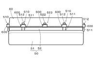
- FIG. 2 is a plan view showing the appearance of the instrument device of FIG.
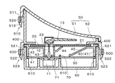
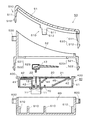
- FIG. 3 is an enlarged cross-sectional view of the instrument device showing the line AA in FIG. 4 is a cross-sectional view of the instrument device showing a state before assembly in FIG.
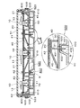
- FIG. 5 is a cross-sectional view showing a portion taken along line BB of FIG.
- FIG. 6 is a cross-sectional view showing an instrument device according to a second embodiment of the present invention.
- FIG. 1 to FIG. 5 show a first embodiment of the present invention, and based on these, an embodiment of the present invention will be described below by taking, for example, an instrument device mounted on an automobile as an example.
- a display board 20 disposed on the front side of a pointer-type indicator 10 such as a speedometer, a tachometer, a fuel meter, a water temperature gauge, and the indicator of the indicator 10
- a circuit board 30 made of a hard material for mounting the main body 11, a middle case 40 made of a resin material disposed on the front side of the circuit board 30 and mounting the display board 20, and a front side of the middle case 40
- the upper case 50 including the see-through panel member 51 that is disposed and made of a resin material that can be seen through at least on the front surface and the facing panel member 52 that partitions the display area of the display panel 20, the middle case 40, and the circuit board 30 are covered.
- a lower case 60 made of a resin material.
- each indicating instrument 10 that displays various information such as a speedometer, a fuel gauge, and a water temperature gauge
- an instrument main body 11 constituting a part of each indicating instrument 10 is assembled on the back side of the circuit board 30.
- a pointer 13 that rotates about the pointer shaft 12 as an axis is press-fitted and fixed to the distal end side of the pointer shaft 12 provided in each instrument body 11.
- a light emitting pointer 13 formed of a transparent synthetic resin such as a polycarbonate resin or an acrylic resin is used.
- the meter body 11 is composed of a movable magnet meter or a stepping motor.
- the meter shaft 11 is disposed behind the circuit board 30 so that the pointer shaft 12 penetrates the shaft hole formed in the circuit board 30. It is mounted and electrically connected to the wiring pattern by appropriate conduction means such as soldering.
- the display plate 20 disposed on the front side of the middle case 40 located behind the pointer 13 is provided with a display unit 21 made of scales, numbers, symbols, and the like.
- the display plate 20 is provided with a through hole 22 at a position corresponding to the pointer shaft 12, and the pointer shaft 12 and the pointer 13 can be connected through the through hole 22.
- the circuit board 30 is made of a hard circuit board in which a wiring pattern (not shown) is applied to a glass epoxy base material, for example, and driving means (not shown) for driving and controlling the instrument body 11, for example, a resistor, Various electronic components (not shown) such as capacitors are conductively connected to the wiring pattern.
- a light source (light emitting diode 70) for transmitting and illuminating the display unit 21 such as the scales and numerals of the display panel 20 facing the inside case 40 of the frame shape and the pointer 13 are illuminated.
- the indicator light source (light emitting diode 71) for mounting is mounted, and the instrument body 11 is assembled and fixed to the back side of the circuit board 30 as described above.
- the middle case 40 has a substantially frame-shaped side wall 41 and a middle part of the side wall 41 in order to support the indicator 10 such as a speedometer, a liquid level gauge, and a water temperature gauge by a white synthetic resin material.
- the light source 71 for pointer illumination described above is disposed on the surface side of the circuit board 30 located at the bottom of the cylindrical portion 43.
- the horizontal wall portion 42 is formed as a placement surface on which the dial 20 is placed.
- the middle case 40 is formed with a reflection wall portion 44 integrally protruding continuously from the middle of the outer peripheral surface of the cylindrical portion 43, and a scale, a number, etc., as described above, are located immediately below the reflection wall portion 44.
- a light source 70 for illumination for transmitting and illuminating the display unit 21 is arranged.
- the middle case 40 also reflects and guides the light from the light source 70 through the reflection wall portion 44, and further reflects and guides the reflected and guided light toward the display portion 21 side of the display plate 20.
- 45 is integrally formed continuously from the horizontal wall portion 42 of the middle case 40.
- the see-through panel member 51 constituting a part of the upper case 50 is made of, for example, a transparent synthetic resin so that the display unit 21 on the display board 20 can be seen through.
- the facing panel member 52 constituting a part of the upper case 50 is made of, for example, black synthetic resin, and is provided so as to partition the display portion 21 area on the display plate 20 into a frame shape so as to be visible. .
- the lower case 60 is made of, for example, a synthetic resin and is formed in a bottomed frame shape so as to cover the back of the circuit board 30 and the outer peripheral surface side of the middle case 40.
- each component of the upper case 50, the middle case 40, and the lower case 60 is used for each component of the upper case 50, the middle case 40, and the lower case 60 as a configuration as an assembly / removal structure of each component of the instrument device in the present embodiment.
- a plurality of locking portions 510 are integrally provided at appropriate positions on the outer peripheral portion of the fluoroscopic panel member 51 at a predetermined interval.
- an elastic arm piece 511 that integrally protrudes from the outer peripheral portion of the fluoroscopic panel member 51 toward the lower case 60 side, and a claw-like shape provided at the distal end portion of the elastic arm piece 511.
- the hook part 512 is formed.
- a frame-like engaging portion 520 is integrally provided at a position facing the engaging portion 510 to receive some of the engaging portions 510 provided on the fluoroscopic panel member 51, and
- a locking portion 523 composed of an elastic arm piece 521 and a hook portion 522 is integrally provided at a proper position on the outer peripheral portion of the facing panel member 52 with a predetermined interval.
- the lower case 60 is provided with an engaging portion 510 including an elastic arm piece 511 and a hook portion 512 provided on the fluoroscopic panel member 51, and an elastic arm piece 521 and a hook portion 522 provided on the facing panel member 52.
- Engaging portions 600 each having a frame shape are provided on the outer peripheral portion of the lower case 60 in order to receive the stopper portions 523, respectively.
- middle case 40 is provided with a flange portion 400 that protrudes outward in the horizontal direction at the upper peripheral edge of the middle case.
- the flange portion 400 is sandwiched and held between the upper case 50 and the lower case 60. It is provided to do.
- the circuit board 30 disposed between the middle case 40 and the lower case 60 is provided so as to be sandwiched and held between the middle case 40 side and the lower case 60 side. ing.
- the lower case 60 is provided with a mounting portion 610 that protrudes from the bottom surface portion of the lower case 60 toward the circuit board 30. A mounting space for the electronic components mounted on the circuit board 30 and the instrument body 11 is secured by the thickness of the mounting portion 610.
- assembly is performed as follows. First, the instrument body 11 constituting a part of each indicating instrument 10 is assembled and fixed to the circuit board 30 and is electrically drawn, and the circuit board 30 is set with the lower case 60 as a reference in this state. . Next, the display panel 20 is placed on the front side of the middle case 40 and set in the lower case 60. Subsequently, the base side of the pointer 13 is press-fitted and fixed to the distal end side of the pointer shaft 12 provided in each instrument body 11. As a result, the circuit board 30, the middle case 40, and the display board 20 to which the instrument body 11 is assembled with the lower case 60 as a reference are set in a stacked state.
- the facing panel member 52 and the see-through panel member 51 which are the upper case 50, are overlapped and assembled on the lower case 60 side, so that the locking portions 523 provided on the facing panel member 52 and the see-through panel member 51, respectively. 510 is fed along the frame-shaped engaging portion 600 provided on the lower case 60 side, and the hook portions 522 and 511 provided in the respective locking portions 523 and 510 are engaged with the frame-shaped engaging portion 600. Retains retention.
- the intermediate case 40 is interposed between the upper case 50 and the lower case 60 only by engaging and fixing the locking portions 523 and 510 provided on the upper case 50 side with the engaging portion 600 of the lower case 60.
- the intermediate case 40 can be clamped and held via the provided flange portion 400.
- the circuit board 30 can be sandwiched and held between the middle case 40 and the lower case 60, and the assembly work can be made more efficient.
- the instrument device can be easily separated by removing only the engaging portion between the engaging portions 523, 510 and the engaging portion 600 provided in the upper and lower cases 50, 60.
- the middle case 40 and the circuit board 30 can be easily removed.
- the pointer illumination light source 71 for illuminating the pointer 13 emits light
- the illumination light is guided inside the cylindrical portion 43 of the middle case 40 and displayed on the display board 20.
- the light guide is guided to the base side of the pointer 13 through the through-hole, and then guided from the base side to the instruction unit, whereby the instruction unit of the pointer 13 is illuminated.
- the light source 70 for illuminating the display unit emits light simultaneously with the illumination of the pointer 13
- the illumination light is reflected by the reflecting wall portion 44 provided immediately above the light source 70, and the reflected light is reflected by the reflecting surface portion 45.
- the display portion 21 of the display board 20 is brightly transmitted and illuminated.
- FIG. 6 shows a second embodiment of the present invention.
- it is placed at an appropriate position on the outer peripheral portion of the fluoroscopic panel member 51.
- a plurality of locking portions 510 are integrally provided at a predetermined interval.
- an elastic arm piece 511 that integrally protrudes from the outer peripheral portion of the fluoroscopic panel member 51 toward the lower case 60 side, and a claw-like shape provided at the distal end portion of the elastic arm piece 511.
- the hook part 512 is formed.
- a frame-like engaging portion 520 is integrally provided at a position facing the engaging portion 510 to receive some of the engaging portions 510 provided on the fluoroscopic panel member 51, and
- a locking portion 523 composed of an elastic arm piece 521 and a hook portion 522 is integrally provided at a proper position on the outer peripheral portion of the facing panel member 52 with a predetermined interval.
- the lower case 60 is provided with an engaging portion 510 including an elastic arm piece 511 and a hook portion 512 provided on the fluoroscopic panel member 51, and an elastic arm piece 521 and a hook portion 522 provided on the facing panel member 52.
- Engaging portions 600 each having a frame shape are provided on the outer peripheral portion of the lower case 60 in order to receive the stopper portions 523, respectively.
- middle case 40 is provided with a flange portion 400 that protrudes outward in the horizontal direction at the upper peripheral edge of the middle case.
- the flange portion 400 is sandwiched and held between the upper case 50 and the lower case 60. It is provided to do.
- the elastic arm piece 401 is integrated with the middle case 40 at an appropriate location (two locations) in the central region of the middle case 40 toward the lower case 60. And a locking portion 403 including a hook portion 402 is provided.
- a mounting portion 620 that is recessed from the bottom surface portion of the middle case 40 is provided at a location corresponding to the locking portion 403 of the middle case 40.
- the mounting portion 620 includes a rising wall portion 621 that is formed to rise toward the circuit board 30 side, and a mounting surface portion 622 that supports the rear side of the circuit board 30 continuously with the rising wall portion 621.
- a recessed space S is formed, an opening window 623 is provided on the mounting surface 622, and a through hole 31 is provided in the circuit board 30 corresponding to the position of the opening window 623.
- the plate 20 is set in a laminated state. Further, the facing panel member 52 and the see-through panel member 51, which are the upper case 50, are overlapped and assembled on the lower case 60 side, so that the locking portions 523 provided on the facing panel member 52 and the see-through panel member 51, respectively. 510 is fed along the frame-shaped engaging portion 600 provided on the lower case 60 side, and the hook portions 522 and 511 provided in the respective locking portions 523 and 510 are engaged with the frame-shaped engaging portion 600. Retains retention.
- the intermediate case 40 is interposed between the upper case 50 and the lower case 60 only by engaging and fixing the locking portions 523 and 510 provided on the upper case 50 side with the engaging portion 600 of the lower case 60.
- the intermediate case 40 can be clamped and held via the provided flange portion 400.
- the circuit board 30 can be sandwiched and held between the middle case 40 and the lower case 60, and the assembly work can be made more efficient.
- the engagement between the engaging portions 600 and the engaging portions 523 and 510 provided in the upper and lower cases 50 and 60 is performed in the same manner as in the first embodiment described above.
- the middle case 40 and the circuit board 30 can be easily removed by removing only the location.
- the circuit board 30 sandwiched and held between the middle case 40 and the lower case 60 is firmly fixed between the lower case 60 by the locking portion 403 provided in the middle case 40.
- An apparatus can be provided, and as a result, the generation of abnormal noise such as stagnation due to resonance or the like can also be suppressed.
- the locking portion 403 provided integrally from the middle case 40 is disposed in the recessed space portion S region of the placement portion 620 including the rising wall portion 621 and the placement surface portion 622, the bottom surface of the lower case 60
- the locking part 403 can be formed without protruding from the side, and the problem that the locking part 403 hits from the outside and breaks can also be prevented.
- a pointer-type indicating instrument 10 will be described as an example. However, it may be used as an indicator by a display device including a liquid crystal display element, for example.
- the circuit board 30 is assembled to the middle case 40, and the middle case 40 with the circuit board 30 assembled is used as the upper case. The work efficiency of assembly / removal can be improved even if it is configured to be sandwiched and fixedly held between 50 and the lower case 60.
- the hook shape of the engaging portion and the engaging portion is not limited to the structure shown in the embodiment, and for example, an engagement formed by a combination of a flat U-shaped elastic piece and a triangular protrusion.
- a hook stop configuration of the stop portion and the engagement portion may be used, and the same effect can be obtained.
- the placement portion 620 provided with the recessed space portion S on which the circuit board 30 is placed is installed according to the components mounted on the circuit board 30, the size of the circuit board 30, the inner case 40, and the like. Should be set.
- the display board 20 may be attached via a double-sided tape, or the display board 20 may be hooked by a hook portion integrally protruding from the middle case 40.
- the fixing means may be set as appropriate.
- the instrument device is not limited to the vehicle instrument device, but is a meter for a special vehicle such as a marine instrument or an agricultural machine or construction machine
- the present invention can be applied to an apparatus and the like, and is not limited to a pointer type or a liquid crystal indicating instrument, but can be applied to an indicator instrument using a display element such as an EL display panel. There is a similar effect.
Abstract
Description
10 指示計器
11 計器本体
12 指針軸
13 指針
20 表示板
21 表示部
22 貫通孔
30 回路基板
31 貫通孔
40 中ケース
41 側壁部
42 水平壁部
43 円筒部
44 反射壁部
45 反射面部
50 上ケース
51 透視パネル部材
52 見返しパネル部材
60 下ケース
70,71 光源(発光ダイオード)
400 フランジ部
401 弾性腕片
402 フック部
403 係止部
510 係止部
511 弾性腕片
512 フック部
520 係合部
521 弾性腕片
522 フック部
523 係止部
600 係合部
610 載置部
620 載置部
621 立ち上がり壁部
622 載置面部
623 開口窓部
DESCRIPTION OF SYMBOLS S Recessed
42 Horizontal wall
43 Cylindrical part
44 Reflecting wall
45 Reflective surface
50 upper case
51 Perspective panel members
52 facing panel member
60 Lower case
70, 71 Light source (light emitting diode)
400 Flange
401 Elastic arm piece
402 Hook
403 Locking part
510
521 Elastic arm piece
522 hook part
523
623 Opening window
Claims (4)
- 指示計器の前面側に配置される表示板、前記指示計器を実装する硬質材料からなる回路基板と、この回路基板の前面側に配置され、前記表示板を載置する樹脂材料からなる中ケースと、この中ケースの前面側に配置され、少なくとも前面が透視可能な樹脂材料からなる上ケースと、前記中ケースと前記回路基板とを覆う樹脂材料からなる下ケースと、を備えてなる計器装置において、前記中ケースの周縁部には、前記上側と下側のケース間に挟んで保持するためのフランジ部が設けられ、前記上ケースまたは前記下ケースの一方側に、それぞれの外周部に間隔を配して係止部が設けられるとともに、この係止部に対応する前記上ケースまたは前記下ケースの他方側に、前記係止部と係合する係合部を設けてなることを特徴とする計器装置。 A display board disposed on the front side of the indicator instrument, a circuit board made of a hard material for mounting the indicator instrument, and a middle case made of a resin material placed on the front side of the circuit board and mounting the display board An instrument device comprising an upper case made of a resin material that is disposed on the front side of the middle case and at least the front surface of which can be seen through, and a lower case made of a resin material that covers the middle case and the circuit board. A flange portion is provided at a peripheral edge portion of the middle case so as to be sandwiched and held between the upper and lower cases, and a gap between each outer peripheral portion is provided on one side of the upper case or the lower case. And an engaging portion that is engaged with the engaging portion is provided on the other side of the upper case or the lower case corresponding to the engaging portion. Instrument device.
- 前記回路基板は、前記下ケースと前記中ケースとの間に挟着保持してなることを特徴とする請求項1に記載の計器装置。 The instrument device according to claim 1, wherein the circuit board is sandwiched and held between the lower case and the middle case.
- 前記下ケースには、その下ケースの底面部分から前記回路基板に向けて突出する載置段部を設けてなることを特徴とする請求項1または請求項2に記載の計器装置。 3. The instrument device according to claim 1, wherein the lower case is provided with a mounting step portion protruding from the bottom surface portion of the lower case toward the circuit board.
- 前記載置段部は、前記回路基板側に向けて立ち上がり形成された立ち上がり壁部と、この立ち上がり壁部と連続して回路基板の背後側を支持する載置部とから形成され、前記載置部に開口窓部が設けられるとともに、この開口窓部位置に対応して前記回路基板に貫通孔を設け、この貫通孔と前記開口窓部に対応して前記中ケースから一体に下ケース側と係合する係止部を設けてなることを特徴とする請求項3に記載の計器装置。
The mounting step portion is formed of a rising wall portion that rises toward the circuit board side, and a mounting portion that supports the back side of the circuit board continuously with the rising wall portion. The circuit board is provided with a through hole corresponding to the position of the opening window, and the lower case side is integrally formed with the through hole and the opening window from the middle case. The instrument device according to claim 3, wherein a locking portion to be engaged is provided.
Priority Applications (2)
| Application Number | Priority Date | Filing Date | Title |
|---|---|---|---|
| US13/518,773 US8988888B2 (en) | 2009-12-25 | 2010-12-14 | Instrument device |
| EP10839230.9A EP2518452B1 (en) | 2009-12-25 | 2010-12-14 | Display device |
Applications Claiming Priority (2)
| Application Number | Priority Date | Filing Date | Title |
|---|---|---|---|
| JP2009293633A JP5493831B2 (en) | 2009-12-25 | 2009-12-25 | Instrument device |
| JP2009-293633 | 2009-12-25 |
Publications (1)
| Publication Number | Publication Date |
|---|---|
| WO2011077997A1 true WO2011077997A1 (en) | 2011-06-30 |
Family
ID=44195527
Family Applications (1)
| Application Number | Title | Priority Date | Filing Date |
|---|---|---|---|
| PCT/JP2010/072427 WO2011077997A1 (en) | 2009-12-25 | 2010-12-14 | Display device |
Country Status (4)
| Country | Link |
|---|---|
| US (1) | US8988888B2 (en) |
| EP (1) | EP2518452B1 (en) |
| JP (1) | JP5493831B2 (en) |
| WO (1) | WO2011077997A1 (en) |
Cited By (1)
| Publication number | Priority date | Publication date | Assignee | Title |
|---|---|---|---|---|
| WO2014185382A1 (en) * | 2013-05-13 | 2014-11-20 | 日本精機株式会社 | Display device |
Families Citing this family (8)
| Publication number | Priority date | Publication date | Assignee | Title |
|---|---|---|---|---|
| JP5493831B2 (en) * | 2009-12-25 | 2014-05-14 | 日本精機株式会社 | Instrument device |
| JP5896217B2 (en) * | 2012-02-22 | 2016-03-30 | 日本精機株式会社 | Display device |
| JP6263842B2 (en) * | 2013-02-22 | 2018-01-24 | 日本精機株式会社 | Display device |
| JP6076154B2 (en) * | 2013-03-15 | 2017-02-08 | 矢崎総業株式会社 | Instrument unit |
| DE102014220348A1 (en) * | 2014-10-08 | 2016-04-14 | Continental Automotive Gmbh | display |
| JP6316741B2 (en) * | 2014-12-24 | 2018-04-25 | 日本精機株式会社 | Display device |
| JP7229984B2 (en) * | 2020-12-09 | 2023-02-28 | 株式会社ホンダアクセス | Instrument panel support device |
| JP7264924B2 (en) * | 2021-02-12 | 2023-04-25 | 矢崎総業株式会社 | projection device |
Citations (6)
| Publication number | Priority date | Publication date | Assignee | Title |
|---|---|---|---|---|
| JPS57124722U (en) * | 1981-01-29 | 1982-08-03 | ||
| JPH08128863A (en) * | 1994-11-01 | 1996-05-21 | Nippon Seiki Co Ltd | Instrument for vehicle |
| JP2001124598A (en) * | 1999-10-29 | 2001-05-11 | Nippon Seiki Co Ltd | Meter device |
| JP2001174292A (en) | 1999-12-16 | 2001-06-29 | Nippon Seiki Co Ltd | Assembling structure of instruments |
| JP2005292074A (en) * | 2004-04-05 | 2005-10-20 | Yazaki Corp | Measuring instrument |
| JP2008075696A (en) | 2006-09-19 | 2008-04-03 | Denso Corp | Fixing structure and instrument for vehicle provided with same |
Family Cites Families (10)
| Publication number | Priority date | Publication date | Assignee | Title |
|---|---|---|---|---|
| JPS57124722A (en) | 1981-01-28 | 1982-08-03 | Nec Corp | Camera |
| DE3800572A1 (en) * | 1987-10-30 | 1989-07-20 | Vdo Schindling | COMBINATION INSTRUMENT FOR MOTOR VEHICLES |
| DE4315027A1 (en) * | 1992-12-02 | 1994-06-09 | Vdo Schindling | Combination instrument |
| US5615080A (en) * | 1993-03-17 | 1997-03-25 | Yazaki Corporation | Meter module, connecting device thereof, wiring harness protector, and connecting device of instrument wiring harness |
| JP2996594B2 (en) * | 1994-08-04 | 2000-01-11 | 矢崎総業株式会社 | Distance integrator unit |
| JP3611263B2 (en) * | 1996-02-19 | 2005-01-19 | カルソニックカンセイ株式会社 | Vehicle instrument |
| JP4414706B2 (en) * | 2002-09-20 | 2010-02-10 | 矢崎総業株式会社 | Dial module and method for manufacturing dial module |
| JP4294303B2 (en) * | 2002-11-29 | 2009-07-08 | 株式会社日本自動車部品総合研究所 | Printed circuit board and meter device |
| JP2007227767A (en) * | 2006-02-24 | 2007-09-06 | Optrex Corp | Electromagnetic shield structure of electronics |
| JP5493831B2 (en) * | 2009-12-25 | 2014-05-14 | 日本精機株式会社 | Instrument device |
-
2009
- 2009-12-25 JP JP2009293633A patent/JP5493831B2/en active Active
-
2010
- 2010-12-14 WO PCT/JP2010/072427 patent/WO2011077997A1/en active Application Filing
- 2010-12-14 US US13/518,773 patent/US8988888B2/en active Active
- 2010-12-14 EP EP10839230.9A patent/EP2518452B1/en active Active
Patent Citations (6)
| Publication number | Priority date | Publication date | Assignee | Title |
|---|---|---|---|---|
| JPS57124722U (en) * | 1981-01-29 | 1982-08-03 | ||
| JPH08128863A (en) * | 1994-11-01 | 1996-05-21 | Nippon Seiki Co Ltd | Instrument for vehicle |
| JP2001124598A (en) * | 1999-10-29 | 2001-05-11 | Nippon Seiki Co Ltd | Meter device |
| JP2001174292A (en) | 1999-12-16 | 2001-06-29 | Nippon Seiki Co Ltd | Assembling structure of instruments |
| JP2005292074A (en) * | 2004-04-05 | 2005-10-20 | Yazaki Corp | Measuring instrument |
| JP2008075696A (en) | 2006-09-19 | 2008-04-03 | Denso Corp | Fixing structure and instrument for vehicle provided with same |
Non-Patent Citations (1)
| Title |
|---|
| See also references of EP2518452A4 |
Cited By (2)
| Publication number | Priority date | Publication date | Assignee | Title |
|---|---|---|---|---|
| WO2014185382A1 (en) * | 2013-05-13 | 2014-11-20 | 日本精機株式会社 | Display device |
| JP2014222180A (en) * | 2013-05-13 | 2014-11-27 | 日本精機株式会社 | Display device |
Also Published As
| Publication number | Publication date |
|---|---|
| JP2011133373A (en) | 2011-07-07 |
| EP2518452B1 (en) | 2017-07-19 |
| EP2518452A4 (en) | 2016-05-25 |
| US8988888B2 (en) | 2015-03-24 |
| EP2518452A1 (en) | 2012-10-31 |
| US20120250280A1 (en) | 2012-10-04 |
| JP5493831B2 (en) | 2014-05-14 |
Similar Documents
| Publication | Publication Date | Title |
|---|---|---|
| JP5493831B2 (en) | Instrument device | |
| JP2011133373A5 (en) | ||
| WO2007086205A1 (en) | Indication instrument | |
| JP2007003630A (en) | Display device | |
| JP5560956B2 (en) | Instrument device | |
| JP2013113590A (en) | Instrument apparatus | |
| JP6201321B2 (en) | Display device | |
| JP6458776B2 (en) | Vehicle display device | |
| JP2012137462A (en) | Pointer type instrument device and method for assembling the same | |
| JP6011293B2 (en) | Vehicle display device | |
| JP2017219310A (en) | Display device | |
| JP5532837B2 (en) | Display device | |
| JP5299846B2 (en) | Waterproof structure in instrumentation | |
| JP5326967B2 (en) | Instrument device | |
| JP2011246082A (en) | Display device | |
| JP6447057B2 (en) | Display device | |
| JP4807079B2 (en) | Instrument device | |
| JP2011158285A (en) | Indicator device | |
| JP6056244B2 (en) | Pointer-type instrument device | |
| JP2011143756A (en) | Vehicle display device attachment structure | |
| JP2011027701A5 (en) | ||
| JP2011028015A (en) | Display device | |
| JP2011185807A (en) | Display device | |
| JP2009128198A (en) | Measuring instrument device | |
| JP5382532B2 (en) | Indicating instrument |
Legal Events
| Date | Code | Title | Description |
|---|---|---|---|
| 121 | Ep: the epo has been informed by wipo that ep was designated in this application |
Ref document number: 10839230 Country of ref document: EP Kind code of ref document: A1 |
|
| WWE | Wipo information: entry into national phase |
Ref document number: 13518773 Country of ref document: US |
|
| NENP | Non-entry into the national phase |
Ref country code: DE |
|
| WWE | Wipo information: entry into national phase |
Ref document number: 1201003178 Country of ref document: TH Ref document number: 5653/DELNP/2012 Country of ref document: IN |
|
| REEP | Request for entry into the european phase |
Ref document number: 2010839230 Country of ref document: EP |
|
| WWE | Wipo information: entry into national phase |
Ref document number: 2010839230 Country of ref document: EP |