WO2011077947A1 - 車両用前照灯 - Google Patents
車両用前照灯 Download PDFInfo
- Publication number
- WO2011077947A1 WO2011077947A1 PCT/JP2010/071982 JP2010071982W WO2011077947A1 WO 2011077947 A1 WO2011077947 A1 WO 2011077947A1 JP 2010071982 W JP2010071982 W JP 2010071982W WO 2011077947 A1 WO2011077947 A1 WO 2011077947A1
- Authority
- WO
- WIPO (PCT)
- Prior art keywords
- reflecting mirror
- axis
- light source
- light
- optical axis
- Prior art date
- Legal status (The legal status is an assumption and is not a legal conclusion. Google has not performed a legal analysis and makes no representation as to the accuracy of the status listed.)
- Ceased
Links
Images








Classifications
-
- F—MECHANICAL ENGINEERING; LIGHTING; HEATING; WEAPONS; BLASTING
- F21—LIGHTING
- F21S—NON-PORTABLE LIGHTING DEVICES; SYSTEMS THEREOF; VEHICLE LIGHTING DEVICES SPECIALLY ADAPTED FOR VEHICLE EXTERIORS
- F21S41/00—Illuminating devices specially adapted for vehicle exteriors, e.g. headlamps
- F21S41/10—Illuminating devices specially adapted for vehicle exteriors, e.g. headlamps characterised by the light source
- F21S41/14—Illuminating devices specially adapted for vehicle exteriors, e.g. headlamps characterised by the light source characterised by the type of light source
- F21S41/141—Light emitting diodes [LED]
- F21S41/155—Surface emitters, e.g. organic light emitting diodes [OLED]
-
- F—MECHANICAL ENGINEERING; LIGHTING; HEATING; WEAPONS; BLASTING
- F21—LIGHTING
- F21S—NON-PORTABLE LIGHTING DEVICES; SYSTEMS THEREOF; VEHICLE LIGHTING DEVICES SPECIALLY ADAPTED FOR VEHICLE EXTERIORS
- F21S41/00—Illuminating devices specially adapted for vehicle exteriors, e.g. headlamps
- F21S41/30—Illuminating devices specially adapted for vehicle exteriors, e.g. headlamps characterised by reflectors
- F21S41/32—Optical layout thereof
- F21S41/36—Combinations of two or more separate reflectors
- F21S41/365—Combinations of two or more separate reflectors successively reflecting the light
Definitions
- the present invention relates to a vehicle headlamp.
- Sufficient brightness is one of the performance requirements for headlights. This is an essential requirement for the basic performance of headlights. In order to achieve sufficient luminance, an approach from two directions is required to increase the efficiency of the optical system and increase the amount of light of the light source itself.
- the former approach is to improve the light utilization efficiency by devising the configuration of the optical system.
- the optical system is downsized, it becomes difficult to maintain the efficiency of the optical system, and therefore it is essential to increase the light quantity of the light source. Therefore, it is necessary to increase the amount of light of the latter approach, that is, the light source itself, but there is a limit to increasing the amount of light with a single LED chip, and it is difficult to secure necessary power.
- the form of using is generally used.
- an optical system for a headlight an optical system composed of an elliptical reflecting mirror and a projection lens is known.
- the light is condensed on the ellipsoidal surface of the ellipsoidal reflector, and light that is substantially parallel to the front of the vehicle is emitted by the projection lens.
- the light source is a point light source
- perfect parallel light can be emitted by adjusting the parameters of the ellipsoid and the projection lens.
- the area of the light source becomes relatively large with respect to the size of the optical system, all the light cannot be emitted as parallel light, and the length in the depth direction (vehicle traveling direction) is long. There is a problem that shortening is difficult.
- a configuration using an elliptical reflecting mirror and a parabolic reflecting mirror in combination is known (see, for example, Patent Documents 1 to 4).
- a light source is arranged at the first focal point of the elliptical surface of the elliptical reflector, basically the second focal point of the elliptical surface and the focal point of the paraboloid are approximately matched, and the light is condensed by the elliptical surface of the elliptical reflective mirror.
- parallel light is emitted on a parabolic surface. According to such a structure, when a point light source is used, the light reflected by the ellipsoid can be made into parallel light.
- each region is set to an optimal shape.
- All the emitted light is configured to be substantially parallel light.
- the configuration of the above conventional example is a configuration in which the best performance is obtained when the light source can be regarded as a point light source. Therefore, when the optical system is downsized and the light source is relatively large, or when the light source has a certain size, the conventional configuration as described above cannot provide sufficient performance. was there. Specifically, the influence of the spread of the light emission position differs depending on the horizontal direction (left-right direction and front-rear direction) with respect to the ground, so that sufficient performance can be obtained when the light source area increases with respect to the light source. difficult.
- Patent Documents 2 to 4 since the paraboloid (or the reflecting surface having a function similar to that) is divided, there are shadowed parts, inflection points, and extreme values, and a specific emission In addition to the problem of increasing the intensity of emitted light at an angle, there are problems that it is difficult to express the shape of the surface by a single formula for connecting a plurality of curved surfaces, and that it is difficult to manufacture.
- the present invention has been made in view of the above circumstances, and in a headlight optical system using a white LED as a light source, it is possible to reduce the size, particularly the front and rear sizes, even though the reflecting surface is smooth and not divided.
- the purpose of the present invention is to provide a vehicular headlamp that can be made compact with high efficiency and excellent cut-off characteristics.
- a surface emitting light source When taking the z axis in the vehicle traveling direction with the vertex of the first reflecting mirror as the origin, the horizontal direction orthogonal to the x axis and the vertical direction as the y axis, In the yz plane, The light source is provided on the curvature center side of the first reflecting mirror; A light beam emitted from the center of the light source in a direction perpendicular to a plane formed by the x-axis and the optical axis of the first reflecting mirror is a principal ray, A point on the second reflecting mirror that is reflected by the first reflecting mirror and incident on the second reflecting mirror is a, The distance from the center of the light source to the point a on the second reflecting mirror is LA, Provided is a vehicular headlamp that satisfies the following expression (1), where fa is a combined focal length of the optical system with respect to the principal ray reflected by the first reflecting mirror and the second reflecting mirror
- FIG. 1 It is a schematic diagram in the yz plane of the vehicle headlamp in the present embodiment.
- the light source is arranged so as to be symmetric in the x-axis direction with respect to the optical axis of the first reflecting mirror, and (a) is from a direction perpendicular to the plane formed from the optical axis of the first reflecting mirror and the x-axis. The case where it sees is shown, (b) is the illumination intensity distribution of the emitted light.
- (A) is the figure which showed the light ray at the time of arrange
- (b) is an enlarged view of (a). It is the figure which showed the light ray at the time of arrange
- FIG. 1 is a schematic diagram in the yz plane when the vehicle headlamp in the present embodiment is viewed from the side.
- the x-axis direction is perpendicular to the traveling direction of the vehicle and horizontal to the ground (left-right direction)
- the y-axis direction is perpendicular to the ground (up-down direction)
- the z-axis direction is the traveling direction of the vehicle.
- the horizontal direction Note that the origin of the xyz axis is the vertex P1 of the first reflecting mirror for convenience.
- the vehicle headlamp 100 includes a light source 2, a first reflecting mirror 1, and a second reflecting mirror 3.
- the light source 2 emits light and is formed in a flat plate shape, for example.
- the surface light emission means that the light emission area is 0.25 mm 2 or more.
- the area of the light emitting surface is a rectangular area formed by a line parallel to the x-axis in contact with the light emitting region so as to surround the light emitting region of the light source 2 and a line parallel to the optical axis A1 of the first reflecting mirror.
- the area of the light emitting surface in the case of having a plurality of light sources 2 is a line parallel to the x axis that is in contact with the light emitting region located on the outermost side so as to surround the plurality of light sources and a line parallel to the optical axis A1 of the first reflecting mirror.
- the area of the rectangle formed by Examples of such a light source 2 include a semiconductor light emitting element such as a white LED or an organic EL element.
- the above formula (5) is a conditional formula that limits the size of the light source 2 in the vehicle traveling direction. By using the surface emitting light source 2 that fits within the conditional formula (5), it is highly efficient, compact and cut. This is effective for obtaining an illuminance distribution with excellent off characteristics.
- the light source 2 is specifically composed of a plurality of LED chips and a phosphor layer formed on the LED chips (not shown).
- the LED chip emits light having a first predetermined wavelength. In the present embodiment, the LED chip emits blue light.
- the wavelength of the LED chip of the present invention and the wavelength of the emitted light from the phosphor are not limited, and the wavelength of the emitted light from the LED chip and the wavelength of the emitted light from the phosphor are in a complementary color relationship and the synthesized light is white. Any combination that provides light can be used.
- an LED chip a well-known blue LED chip can be used.
- the blue LED chip any existing one including In x Ga 1-x N system can be used.
- the emission peak wavelength of the blue LED chip is preferably 440 to 480 nm.
- the LED chip is mounted on the substrate and directly radiated upward or sideward, or the blue LED chip is mounted on a transparent substrate such as a sapphire substrate, and bumps are formed on the surface thereof. Any form of LED chip, such as a so-called flip chip connection type, in which it is formed and turned over and connected to an electrode on a substrate, can be applied.
- the light source 2 is preferably asymmetric in the x-axis direction with respect to the optical axis A1 of the first reflecting mirror 1.
- the arrangement or shape of the light source 2 is asymmetrical in the x-axis direction with the optical axis A1 of the first reflecting mirror 1 interposed therebetween, so that the illuminance distribution is also asymmetrical. (See FIG. 3B).
- FIG. 3A and 2B are illuminance distributions when the arrangement or shape of the light source 2 is symmetric in the x-axis direction with respect to the optical axis A1 of the first reflecting mirror 1.
- the phosphor layer has a phosphor that converts light having a first predetermined wavelength emitted from the LED chip into a second predetermined wavelength.
- blue light emitted from the LED chip is converted into yellow light.
- the phosphor used for such a phosphor layer uses an oxide or a compound that easily becomes an oxide at a high temperature as a raw material of Y, Gd, Ce, Sm, Al, La and Ga, and converts them into a stoichiometric amount.
- the raw material is obtained by thoroughly mixing in a theoretical ratio.
- a coprecipitated oxide obtained by calcining a solution obtained by coprecipitation of oxalic acid with a solution obtained by dissolving a rare earth element of Y, Gd, Ce, and Sm in an acid at a stoichiometric ratio, and aluminum oxide and gallium oxide. Mix to obtain a mixed raw material.
- the compact can be packed in a crucible and fired in air at a temperature range of 1350 to 1450 ° C. for 2 to 5 hours to obtain a sintered body having the phosphor emission characteristics.
- the first reflecting mirror 1 has a curvature, and the surface (reflecting surface) facing the light source 2 is a concave surface.
- the first reflecting mirror 1 is configured by a surface based on an ellipse.
- the first reflecting mirror 1 has a substantially semi-elliptical shape having a curvature obtained by vertically cutting an elliptical sphere having a hollow inside along a plane including the short axis 1b.
- a reflecting mirror may be formed by forming a reflective surface by forming a metal reflective layer or a dielectric multilayer film layer on the surface by vapor deposition or the like after molding glass or a resin substrate.
- the reflection surface of the inner surface 13 (surface facing the light source 2) of the first reflecting mirror 1 can be easily obtained with a high reflectance in a wide wavelength range, and is made of a metal such as Al or Ag or a metal film, for example. Preferably it is.
- the reflective surface is preferably made of a material that hardly deteriorates against heat or light from the LED chip.
- the cut surface having a shape obtained by cutting an elliptical sphere along the minor axis 1 b direction faces the rear side in the vehicle traveling direction or the y-axis direction side as shown in FIG. ing.
- the second reflecting mirror 3 is provided behind or in the same position as the first reflecting mirror 1 in the vehicle traveling direction.
- the second reflecting mirror 3 has a curvature, and a surface (reflecting surface) facing the light source 2 side is a concave surface.
- the curvature here refers to a curvature in a direction perpendicular to a plane formed by the x-axis and the optical axis A1 of the first reflecting mirror 1.
- the second reflecting mirror 3 may be configured by cutting an object having a reflecting curved surface such as an elliptic sphere or a hyperboloid, or the surface shape is required for the second reflecting mirror 3.
- the metal may be directly molded so as to be spherical, or a reflective mirror may be formed by forming a reflective surface by forming a metal reflective layer on the surface by vapor deposition after molding glass or a resin substrate.
- the reflecting surface of the inner surface 31 (the surface facing the light source 2) of the second reflecting mirror 3 can be easily obtained with a high reflectance in a wide wavelength range, for example, composed of a metal such as Al or Ag or a metal film. Preferably it is.
- the reflective surface is preferably made of a material that hardly deteriorates against heat or light from the LED chip.
- the 1st reflective mirror 1 and the 2nd reflective mirror 3 are reflective mirrors which have a curvature, and have the surface shape which can be described with a single type
- first reflecting mirror 1 and the second reflecting mirror 3 are not limited to the shapes shown in FIG. 1, but may be reflecting surfaces based on an ellipsoid, a paraboloid, a hyperboloid, and a decentered sphere, respectively.
- the shape of the reflecting surface of the first reflecting mirror 1 is different in the x-axis direction and the direction perpendicular to the plane constituted by the x-axis and the optical axis A1 of the first reflecting mirror 1.
- the shape of the reflecting surface of the second reflecting mirror 3 is different in the x-axis direction and in a direction perpendicular to the plane formed by the x-axis and the optical axis A2 of the second reflecting mirror 1.
- the direction perpendicular to the x axis in the case of the first reflecting surface 1, the direction perpendicular to the plane formed by the x axis and the optical axis A 1 of the first reflecting mirror 1, in the case of the second reflecting surface 3
- an anamorphic surface with a tight curvature in the x-axis direction a direction perpendicular to the plane formed by the x-axis and the optical axis A2 of the second reflecting mirror 1
- the x-axis direction A wide illuminance distribution can be obtained.
- an illuminance distribution spread in the x-axis direction can be obtained.
- one or both of the first reflecting mirror 1 and the second reflecting mirror 3 is a polynomial aspherical surface. More arbitrary illuminance distribution can be obtained by using a polynomial aspherical reflecting surface.
- one or both of the first reflecting mirror 1 and the second reflecting mirror 3 is asymmetrical in the left and right (x-axis direction) across the optical axis A1 of the first reflecting mirror 1.
- the illuminance distribution can also be asymmetric, and as a result, it is easy to see pedestrians and signs without being dazzled by oncoming vehicles.
- the center S0 of the light source 1 extends from the center S0 of the light source 2 in a direction perpendicular to the plane formed by the x axis and the optical axis A1 of the first reflecting mirror 1.
- the main ray is the light emitted from A point on the second reflecting mirror 3 where the principal ray is reflected by the first reflecting mirror 1 and incident on the second reflecting mirror 3 is defined as a,
- the distance from the center S0 of the light source 1 to the point a on the second reflecting mirror 3 is LA,
- the combined focal length of the entire optical system with respect to the principal ray reflected by the first reflecting mirror 1 and the second reflecting mirror 3 is represented by fa, the following formula (1) is satisfied.
- the optical axis A1 of the first reflecting mirror 1 is 1.
- the axis passing through the apex P1 of the first reflecting mirror 1 perpendicular to the tangent plane in contact with the apex P1 of the first reflecting mirror 1 is defined as the optical axis A1 of the first reflecting mirror 1.
- the intersection line of the z-axis cross section perpendicular to the plane on which the surface emitting light source is placed is defined as the optical axis of the first reflecting mirror.
- the intersection is the vertex P1 of the first reflecting mirror 1, and (b) the first reflecting mirror 1 is not shown.
- the point of the first reflecting mirror is the point where the perpendicular line drawn from the end point closest to the light source of the first reflecting mirror to the optical axis of the first reflecting mirror intersects. Let it be a vertex.
- the center S0 of the light source 2 is surrounded by lines parallel to the x axis and the optical axis A1 of the first reflecting mirror 1, respectively. Refers to the center of the rectangle.
- the concave reflecting surface is a free-form surface (for example, Example 2 described later), or when the light beam is reflected on a part of the optical surface away from the apex (for example, Example 1 described later), or the light beam is a plurality of optical
- the combined focal length fa of the optical system with respect to the principal ray reflected by the first reflecting mirror 1 and the second reflecting mirror 3 in the case of the present embodiment is parallel to the principal ray emitted from the center S0 of the light source and is principal. 0.001 using an angle 2u ′ formed after two light beams, which are shifted from the light beam by ⁇ 0.001 mm on the optical axis A1 of the first reflecting mirror, are reflected by the second reflecting mirror 3 through the first reflecting mirror 1. / U ′.
- the distance from the center S0 of the light source 2 to the first intersection b where the optical axis A1 of the first reflector 1 and the second reflector 3 intersect is ZL, and the second at the first intersection b.
- the focal length of the reflecting mirror 3 is fb, it is desirable to satisfy the following formula (2).
- the end point of the second reflecting mirror closest to the optical axis of the first reflecting mirror is set to the first end point.
- the distance from the vertex position P1 of the first reflecting mirror 1 to the first focal position f11 closest to the vertex position P1 of the first reflecting mirror 1 on the curvature center side of the first reflecting mirror 1 is defined as F11.
- the distance from the apex position P1 of the reflector 1 to the second focus f12 position different from the first focus f11 is F12, and the first reflector 1 is fb away from the first intersection b toward the first reflector 1 side.
- the above formula (4) is a conditional expression of a compact optical system for differentiating from the conventional known invention. By satisfying the above formula (4), more compact and parallel light can be emitted. In addition, if it deviates from the range of this formula (4), it becomes the structure of a large optical system as in the conventional known invention.
- FIG. 5 shows a case where a light shielding member is arranged in order to obtain better cut-off characteristics.
- the first reflecting mirror 1 and the second reflecting mirror 3 are reflecting surfaces based on a hyperboloid, and the light shielding member 4 is provided between the first reflecting mirror 1 and the second reflecting mirror 3 in the vehicle traveling direction. Is arranged.
- the light shielding member 4 By arranging the light shielding member 4 in this way, it is possible to obtain a light distribution having a cut-off line suitable as a beam that passes on the oncoming vehicle side, and also for the pedestrian side to confirm the pedestrian and the sign. The light distribution without the cut-off line.
- FIG. 6 shows a case where an auxiliary reflector is arranged.
- the first reflecting mirror 1 and the second reflecting mirror 3 are reflecting surfaces based on a hyperboloid, and auxiliary reflection is performed between the first reflecting mirror 1 and the second reflecting mirror 3 in the vehicle traveling direction.
- a mirror 5 is arranged.
- Such an auxiliary reflecting mirror 5 makes it possible to obtain a desired illuminance distribution.
- the auxiliary reflecting mirror 5 may be a plane mirror or a mirror such as a cylinder pipe.
- the light source 2 is not shown due to the drawing, but the light source 2 is arranged at the same position as in FIG.
- the light source 2, the first reflecting mirror 1, and the second reflecting mirror 3 are configured, and by satisfying the above formula (1), between the first reflecting mirror 1 and the second reflecting mirror 3. Reduce the distance. As a result, it is effective when the light source 2 is not a point light source but a surface light source, and can be made compact as compared with a conventional optical system. Further, it is possible to obtain an illuminance distribution that is highly efficient and excellent in cut-off characteristics.
- a rotationally symmetric polynomial aspherical expression centered on the optical axis z can be expressed by the following equation (1).
- Z is the sag amount of curvature
- y is the height from the optical axis
- R is the radius of curvature in the yz plane
- ⁇ is the conic coefficient
- the focal point of the reflecting mirror is as follows. 1. In the case of an ellipse Considering a two-dimensional ellipse, it has two focal points at a position (a 2 -b 2 ) 1/2 away from the center of the ellipse (intersection of the major axis and minor axis). 2. In the case of a hyperboloid When considering a two-dimensional hyperbola, it has two focal points at a position (a 2 + b 2 ) 1/2 away from the center of the hyperbola (the intersection of the two asymptotes of the hyperbola).
- Rx curvature radius in x direction
- Ry curvature radius in y direction
- kx conic coefficient in x direction
- ky conic coefficient in y direction.
- N is the number of polynomial coefficients
- Ai is the coefficient of the i-th term.
- the vertex coordinates ( ⁇ , ⁇ ) of the second reflecting mirror shown in Tables 1 to 3 are the x-axis direction in the ⁇ direction, the optical axis A1 direction of the first reflecting mirror in the ⁇ direction, and the origin of the coordinates is the xyz coordinate system.
- the coordinate positions in the orthogonal coordinate system of ⁇ that are matched (with P1 as the origin) are shown. That is, when the xyz coordinate system is rotated in the z ⁇ y direction around the x axis by the angle ⁇ formed by the optical axis A1 of the first reflecting mirror and the y axis, x ⁇ ⁇ , y ⁇ ⁇ , and z ⁇ ⁇ . Indicates the coordinate position in the coordinate system.
- Examples 4, 7 to 11 and Comparative Examples 1 and 2 are biconic surfaces, and Examples 2, 3, 5, and 6 are xy polynomial surfaces.
- Example 6 a light shielding plate as shown in FIG. 4 was inserted only in the positive direction of the x axis (so as to be asymmetric with respect to the optical axis A1 of the first reflecting mirror).
- R V / S [mm]
- S Area of light emitting surface [mm 2 ]
- V Volume of the optical system [mm 3 ] (the volume of the optical system is the maximum horizontal length of the optical system ⁇ the maximum length in the vertical direction ⁇ the maximum length in the vehicle traveling direction)
- S 3 [mm 2 ]
- V 12,000,000 [mm 3 ] (maximum horizontal length: 200 [mm], vertical maximum length: 60 [Mm], the maximum length in the vehicle traveling direction: 100 [mm]) is typical
- R 400000 [mm].
- the case of R ⁇ 62500 which is 1 / 6.4, is defined as a small optical system.
- ⁇ optical system efficiency / R
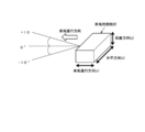
- Optical system efficiency forward outgoing light [Lumen] / outgoing light from the light source [Lumen] Forward: Within ⁇ 25 ° in the horizontal direction from the traveling direction of the vehicle and within ⁇ 10 ° to 10 ° in the vertical direction (see FIG. 7).
- FIGS. 8 (a) and 8 (b) at a position 10 m ahead from the vehicle headlamps of Examples 1 to 11 and Comparative Examples 1 to 2, A virtual screen was provided so that a simulation was performed when the vehicle headlight was used for irradiation. The simulation was performed assuming a Lambertian LED as the light source.
- the illuminance distribution [lx] of the emitted light at this time is shown in FIGS. 9 to 21, the horizontal axis represents the horizontal distance [mm], and the vertical axis represents the vertical distance [mm]. Note that the illuminance distribution in the figure is a case where one vehicle headlamp is used.
- Conditions with good illuminance distribution are (i) a 400 lumin light source, (ii) the strongest central illuminance of 100 lx or more on the screen 10 m ahead from the light source position, and (iii) no hot spot ( (There are no more than two places with the strongest illuminance), and (iv) it does not spread drastically in the y-axis direction.
Landscapes
- Engineering & Computer Science (AREA)
- Physics & Mathematics (AREA)
- Microelectronics & Electronic Packaging (AREA)
- Optics & Photonics (AREA)
- General Engineering & Computer Science (AREA)
- Non-Portable Lighting Devices Or Systems Thereof (AREA)
Abstract
白色LEDを光源としてヘッドライト光学系において、反射面が滑らかで分割されていないにも関わらず、小型化、特に前後サイズの薄型化が可能でコンパクト化でき、また、高効率でかつカットオフ特性に優れた車両用前照灯を提供する。 車両用前照灯は、面発光の光源と第1反射鏡と第2反射鏡とを有し、車両進行方向に向かってz軸を取り、それに直交する水平方向をx軸、鉛直方向をy軸とした際に、yz平面内において、第1反射鏡1の曲率中心側に光源が設けられ、x軸と第1反射鏡1の光軸とで構成される平面に対して垂直な方向に、光源2の中心から出射した光線を主光線とし、主光線が第1反射鏡1で反射され第2反射鏡に入射する第2反射鏡上の点をaとし、光源の中心から第2反射鏡上の点までの距離をLAとし、第1反射鏡及び第2反射鏡によって反射された主光線に対する光学系の合成焦点距離をfaとすると、下記式を満たす。 4fa≧LA
Description
本発明は、車両用前照灯に関する。
近年、環境面への配慮などから小型・軽量なヘッドライトが望まれており、ヘッドライトの光源として白色LEDを使用することが期待されている。
ヘッドライトに要求される性能の一つに十分な輝度が挙げられる。これはヘッドライトの基本的な性能として欠かすことのできない要件である。十分な輝度を達成するためには、光学系の効率を上げること、光源自体の光量を増加させることの2方向からのアプローチが必要である。
前者のアプローチでは、光学系の構成を工夫して光利用効率の向上を図ることである。ただし、光学系を小型化すると光学系の効率を保つのは困難となるため、光源の光量増加が必須となる。従って後者のアプローチ、すなわち光源自体の光量を増加させる必要があるが、LEDチップ単体で光量を増加させるには限界があり必要なパワーを確保することが困難であることから、複数個のチップを使用するという形態が一般的に用いられている。
以上のように、LEDを光源としたヘッドライト光学系では、光学系の小型化が要望されるとともに、複数個のLEDチップを使用する必要があることから、光学系の大きさに対する発光面の面積が相対的に大きくならざるを得ない。このことは、光源が点光源としてみなせないということであり光学系の構成を考える上で、発光位置の空間的な広がりを考慮する必要があることを意味している。
従来より、ヘッドライト用の光学系としては、楕円反射鏡と投影レンズからなる構成のものが知られている。この場合、楕円反射鏡の楕円面で集光し、投影レンズで車両前方にほぼ平行な光を出射する。光源が点光源の場合には、楕円面、投影レンズのパラメータを調整することで、完全な平行光を出射することができる。しかしながら、このような光学系では、光源の面積が光学系の大きさに対して相対的に大きくなった場合に全ての光を平行光として出射できないことや、奥行き方向(車両進行方向)の長さの短縮が難しいといった課題がある。
その他、ヘッドライト用の光学系として、楕円反射鏡と放物面反射鏡とを組み合わせて用いた構成のものが知られている(例えば、特許文献1~4参照)。この場合、楕円反射鏡の楕円面の第1焦点に光源を配置し、基本的には楕円面の第2焦点と放物面の焦点を概略一致させ、楕円反射鏡の楕円面で集光し、投影レンズの代わりに放物面で平行光を出射する。このような構成によれば、点光源を使用した場合には楕円面で反射された光を平行光とすることができる。また、楕円面で反射してから放物面で反射する光路、直接放物面に入射する光路などの光路に応じて、放物面を分割し各領域を最適な形状に設定することで、全ての出射光を略平行光にすることができる構成としている。これらの構成は、楕円反射鏡と投影レンズからなる光学系と比較して、光路を折り曲げているため車両進行方向のサイズを短縮することができるという利点がある。
しかしながら、上記従来例の構成は光源が点光源とみなせる場合に、最良の性能が得られる構成である。そのため、光学系が小型化し、相対的に光源が大きくなった場合や、光源がある大きさを有している場合には、上述したような従来の構成では十分な性能が得られないという課題があった。具体的には、発光位置の広がりの影響は、地面に対して水平な方向(左右方向と前後方向)によって異なるため、光源面積が光源に対して大きくなった場合に十分な性能を得ることが難しい。
また、特許文献1のように第1反射鏡の第1焦点近傍に設置した光源から出射した光を一度、第1反射鏡の第2焦点位置に集光させるような配置を用いている場合、光が最終的に出射される車両進行方向のサイズ短縮が難しかった。
また、特許文献2~4の場合、放物面(もしくはそれに類似の機能を持った反射面)が分割されているため、影になる部分や変曲点や極値が存在し、特定の出射角度で出射光線強度が強くなるという課題の他、複数の曲面をつなぎ合わせるため面の形状を単一の式で表現することが難しく、また、製造が困難であるという課題があった。
本発明は、上記事情に鑑みてなされたもので、白色LEDを光源としてヘッドライト光学系において、反射面が滑らかで分割されていないにも関わらず、小型化、特に前後サイズの薄型化が可能でコンパクト化でき、また、高効率でかつカットオフ特性に優れた車両用前照灯を提供することを目的としている。
本発明の一態様によれば、面発光の光源と、
第1反射鏡と、
第2反射鏡と、を有し、
前記第1反射鏡の頂点を原点として車両進行方向に向かってz軸を取り、それに直交する水平方向をx軸、鉛直方向をy軸とした際に、
yz平面内において、
前記第1反射鏡の曲率中心側に前記光源が設けられ、
x軸と前記第1反射鏡の光軸とで構成される平面に対して垂直な方向に、前記光源の中心から出射した光線を主光線とし、
前記主光線が前記第1反射鏡で反射され、前記第2反射鏡に入射する前記第2反射鏡上の点をaとし、
前記光源の中心から、前記第2反射鏡上の点aまでの距離をLAとし、
前記第1反射鏡及び前記第2反射鏡によって反射された前記主光線に対する光学系の合成焦点距離をfaとすると、下記式(1)を満たすことを特徴とする車両用前照灯が提供される。
第1反射鏡と、
第2反射鏡と、を有し、
前記第1反射鏡の頂点を原点として車両進行方向に向かってz軸を取り、それに直交する水平方向をx軸、鉛直方向をy軸とした際に、
yz平面内において、
前記第1反射鏡の曲率中心側に前記光源が設けられ、
x軸と前記第1反射鏡の光軸とで構成される平面に対して垂直な方向に、前記光源の中心から出射した光線を主光線とし、
前記主光線が前記第1反射鏡で反射され、前記第2反射鏡に入射する前記第2反射鏡上の点をaとし、
前記光源の中心から、前記第2反射鏡上の点aまでの距離をLAとし、
前記第1反射鏡及び前記第2反射鏡によって反射された前記主光線に対する光学系の合成焦点距離をfaとすると、下記式(1)を満たすことを特徴とする車両用前照灯が提供される。
4fa≧LA・・・式(1)
前記第1反射鏡の光軸とは、
1.前記第1反射鏡に頂点が存在する場合、前記第1反射鏡の頂点に接する接平面に垂直な前記第1反射鏡の頂点を通る軸を前記第1反射鏡の光軸とし、
2.前記第1反射鏡が頂点を含まない曲面の場合、前記光源が乗っている平面とその平面に垂直に交わるz軸を含む面との交線を前記第1反射鏡の光軸とする。
前記第1反射鏡の光軸とは、
1.前記第1反射鏡に頂点が存在する場合、前記第1反射鏡の頂点に接する接平面に垂直な前記第1反射鏡の頂点を通る軸を前記第1反射鏡の光軸とし、
2.前記第1反射鏡が頂点を含まない曲面の場合、前記光源が乗っている平面とその平面に垂直に交わるz軸を含む面との交線を前記第1反射鏡の光軸とする。
また、このとき、
(a)前記第1反射鏡と前記第1反射鏡の光軸とが交わる場合、その交点を前記第1反射鏡の頂点とし、(b)前記第1反射鏡と前記第1反射鏡の光軸とが交わらない場合、前記第1反射鏡の最も光源に近い側の端点から前記第1反射鏡の光軸に下ろした垂線とが交わる点を前記第1反射鏡の頂点とする。
(a)前記第1反射鏡と前記第1反射鏡の光軸とが交わる場合、その交点を前記第1反射鏡の頂点とし、(b)前記第1反射鏡と前記第1反射鏡の光軸とが交わらない場合、前記第1反射鏡の最も光源に近い側の端点から前記第1反射鏡の光軸に下ろした垂線とが交わる点を前記第1反射鏡の頂点とする。
本発明によれば、高効率でコンパクトかつカットオフ特性に優れた照度分布を得ることができる。
以下、図面を参照しながら本発明の好ましい実施形態について説明する。
図1は、本実施形態における車両用前照灯を側方から見た場合のyz平面における模式図である。
なお、図中、x軸方向は車両の進行方向と垂直で地面と水平な方向(左右方向)、y軸方向は地面と鉛直な方向(上下方向)、z軸方向は車両進行方向で地面と水平な方向とする。なお、xyz軸の原点は便宜上第1反射鏡の頂点P1とする。以下、特に注意書きが無ければ下記文章内において出てくる様々な値及び記号はx=0のyz平面における値及び記号のことを指すものとする。
図1に示すように、車両用前照灯100は、光源2と、第1反射鏡1と、第2反射鏡3と、を備える。
光源2は、面発光をし、例えば平板状に形成されている。ここで、面発光とは、発光の面積が0.25mm2以上のものを示す。なお、発光面の面積は、光源2の発光領域を囲むように発光領域に接するx軸に平行な線と第1反射鏡の光軸A1に平行な線で形成される長方形の面積とする。また、光源2を複数有する場合の発光面の面積は、複数の光源を囲むように最外部に位置する発光領域に接するx軸に平行な線と第1反射鏡の光軸A1に平行な線で形成される長方形の面積とする。このような光源2としては、白色LEDなどの半導体発光素子又は有機EL素子などが挙げられる。
また、光源2の発光面(図1では上側の面)の面積Sは、第1反射鏡の光軸A1方向の長さをLとし、それと直交する水平方向(x軸方向)の長さをMとすると、S=M×Lと表せ、下記式(5)を満たすことが好ましい。
L≦3(mm)・・・式(5)
上記式(5)は、光源2の車両進行方向の大きさを制限した条件式であって、この条件式(5)内に収まる面発光の光源2とすることにより、高効率でコンパクトかつカットオフ特性に優れた照度分布を得るのに有効となる。
上記式(5)は、光源2の車両進行方向の大きさを制限した条件式であって、この条件式(5)内に収まる面発光の光源2とすることにより、高効率でコンパクトかつカットオフ特性に優れた照度分布を得るのに有効となる。
光源2は、具体的には、図示しないが複数個のLEDチップとLEDチップ上に形成された蛍光体層から構成されている。LEDチップは、第1の所定波長の光を出射するものであり、本実施形態においては青色光を出射するようになっている。ただし、本発明のLEDチップの波長及び蛍光体の出射光の波長は限定されず、LEDチップによる出射光の波長と、蛍光体による出射光の波長とが補色関係にあり合成された光が白色光となる組み合わせであるものであれば、使用可能である。
なお、このようなLEDチップとしては、公知の青色LEDチップを用いることができる。青色LEDチップとしては、InxGa1-xN系をはじめ既存のあらゆるものを使用することができる。青色LEDチップの発光ピーク波長は440~480nmのものが好ましい。また、LEDチップの形態としては、基板上にLEDチップを実装し、そのまま上方または側方に放射させるタイプ、又は、サファイア基板などの透明基板上に青色LEDチップを実装し、その表面にバンプを形成した後、裏返して基板上の電極と接続する、いわゆるフリップチップ接続タイプなど、どのような形態のLEDチップでも適用することが可能である。
また、光源2は、第1反射鏡1の光軸A1に関してx軸方向に非対称であることが好ましい。具体的には、図3(a)に示すように光源2の配置又は形状を第1反射鏡1の光軸A1を挟んでx軸方向に非対称にすることによって、照度分布も非対称にすることができる(図3(b)参照)。その結果、対向車にまぶしくなく歩行者や標識が視認し易くなる。図2(a)、(b)は、光源2の配置又は形状を第1反射鏡1の光軸A1に関してx軸方向に対称とした場合の照度分布である。
蛍光体層は、LEDチップから出射される第1の所定波長の光を第2の所定波長に変換する蛍光体を有している。本実施の形態では、LEDチップから出射される青色光を黄色光に変換するようになっている。
このような蛍光体層に用いられる蛍光体は、Y、Gd、Ce、Sm、Al、La及びGaの原料として酸化物、又は高温で容易に酸化物になる化合物を使用し、それらを化学量論比で十分に混合して原料を得る。又は、Y、Gd、Ce、Smの希土類元素を化学量論比で酸に溶解した溶解液を蓚酸で共沈したものを焼成して得られる共沈酸化物と、酸化アルミニウム、酸化ガリウムとを混合して混合原料を得る。これにフラックスとしてフッ化アンモニウム等のフッ化物を適量混合して加圧し成形体を得る。成形体を坩堝に詰め、空気中1350~1450℃の温度範囲で2~5時間焼成して、蛍光体の発光特性を持った焼結体を得ることができる。
第1反射鏡1は、曲率を有し、光源2側を向く面(反射面)が凹面とされている。ここで言う曲率とは、x軸と第1反射鏡1の光軸A1とで構成される平面に対して垂直なx=0でのyz平面内での曲率を言う。
本実施形態では、第1反射鏡1が楕円を基調とした面で構成されている場合を例として説明する。
例えば図1に示すように、第1反射鏡1は、内部が空洞の楕円球を、短軸1bを含む平面に沿って垂直に切断された曲率を有する略半楕円形状をなしている。但し、第1反射鏡1を形成する際に上記のように切断して成形する必要はなく、表面形状が第1反射鏡1で必要とされる略半楕円球状となるように金属を直接成形してもよいし、ガラスや樹脂基板等を成形した後に表面に蒸着などにより金属反射層や誘電体多層膜層を形成して反射面を構成することで反射鏡としてもよい。第1反射鏡1の内面13(光源2に対向する面)の反射面は広い波長域で高い反射率を容易に得ることが可能な、例えばAl、Ag等の金属あるいは金属膜で構成されていることが好ましい。また、反射面は、熱あるいはLEDチップからの光に対して劣化しにくい材料を用いるのが好ましい。
このような第1反射鏡1は、楕円球を短軸1b方向に沿って切断した形状である切断面が車両進行方向の後方側または図1(b)に示すようにy軸方向側を向いている。
第2反射鏡3は、第1反射鏡1よりも車両進行方向の後方または同じ位置に設けられている。第2反射鏡3は曲率を有し、光源2側を向く面(反射面)が凹面とされている。ここで言う曲率とは、x軸と第1反射鏡1の光軸A1とで構成される平面に対して垂直な方向の曲率を言う。
第2反射鏡3も第1反射鏡1と同様、楕円球や双曲面などの反射曲面を有する物体を切断して構成してもよいし、表面形状が第2反射鏡3で必要とされる球状となるように金属を直接成形してもよいし、ガラスや樹脂基板等を成形した後に表面に蒸着などにより金属反射層を形成して反射面を構成することで反射鏡としてもよい。
第2反射鏡3の内面31(光源2に対向する面)の反射面は広い波長域で高い反射率を容易に得ることが可能な、例えばAl、Ag等の金属あるいは金属膜で構成されていることが好ましい。また、反射面は、熱あるいはLEDチップからの光に対して劣化しにくい材料を用いるのが好ましい。
なお、第1反射鏡1及び第2反射鏡3は、曲率を有する反射鏡であり、単一の式で記述できる面形状を有するが、曲率を有する面の一部が使用されていれば実際に使用される光学面は曲率の頂点を含んでいる必要はない。
また、第1反射鏡1及び第2反射鏡3は、図1に示す形状に限らず、それぞれ楕円面、放物面、双曲面、偏球面を基調とした反射面としても良い。
第1反射鏡1は、x軸方向と、x軸と第1反射鏡1の光軸A1とで構成される平面に対して垂直な方向とで反射面の形状が異なることが好ましい。また、第2反射鏡3は、x軸方向と、x軸と第2反射鏡1の光軸A2とで構成される平面に対して垂直な方向とで反射面の形状が異なることが好ましい。このように第1反射鏡1及び第2反射鏡3のいずれか一方又は両方の反射面を、x軸方向とそれに垂直な方向とでそれぞれパワーを変えることによって、任意の照度分布を得ることができる。例えば、x軸に垂直な方向(第1反射面1の場合はx軸と第1反射鏡1の光軸A1とで構成される平面に対して垂直な方向、第2反射面3の場合はx軸と第2反射鏡1の光軸A2とで構成される平面に対して垂直な方向)には曲率がきつくx軸方向には曲率が緩いアナモフィックな面を用いることで、x軸方向に広がった照度分布を得ることができる。また、例えばx軸に垂直な方向には楕円を基調とした面を、x軸方向には双曲面を基調とした面を用いることで、x軸方向に広がった照度分布を得ることができる。
また、第1反射鏡1及び第2反射鏡3のいずれか一方又は両方は、多項式非球面であることが好ましい。多項式非球面形状の反射面を用いることによって、より任意の照度分布を得ることができる。
また、第1反射鏡1及び第2反射鏡3のいずれか一方又は両方は第1反射鏡1の光軸A1を挟んで左右(x軸方向)に非対称であることが好ましい。左右非対称とすることによって、照度分布も非対称にすることができ、その結果、対向車にまぶしくなく歩行者や標識を視認し易くなる。
ここで、光源2、第1反射鏡1及び第2反射鏡3の配置関係等について詳細に説明する。
図1に示すように、yz平面内において、光源2の中心S0から、x軸と第1反射鏡1の光軸A1とで構成される平面に対して垂直な方向に、光源1の中心S0から出射した光線を主光線とし、
主光線が、第1反射鏡1で反射され、第2反射鏡3に入射する第2反射鏡3上の点をaとし、
光源1の中心S0から、第2反射鏡3上の点aまでの距離をLAとし、
第1反射鏡1及び第2反射鏡3によって反射された主光線に対する光学系全体での合成焦点距離をfaとすると、下記式(1)を満たす。
主光線が、第1反射鏡1で反射され、第2反射鏡3に入射する第2反射鏡3上の点をaとし、
光源1の中心S0から、第2反射鏡3上の点aまでの距離をLAとし、
第1反射鏡1及び第2反射鏡3によって反射された主光線に対する光学系全体での合成焦点距離をfaとすると、下記式(1)を満たす。
4fa≧LA・・・式(1)
第1反射鏡1の光軸A1は、
1.第1反射鏡1に頂点P1が存在する場合、第1反射鏡1の頂点P1に接する接平面に垂直な第1反射鏡1の頂点P1を通る軸を第1反射鏡1の光軸A1とし、
2.第1反射鏡1が頂点P1を含まない曲面の場合、図示しないが、上記面発光光源が乗っている平面と垂直に交わるz軸断面の交線を第1反射鏡の光軸とする。
第1反射鏡1の光軸A1は、
1.第1反射鏡1に頂点P1が存在する場合、第1反射鏡1の頂点P1に接する接平面に垂直な第1反射鏡1の頂点P1を通る軸を第1反射鏡1の光軸A1とし、
2.第1反射鏡1が頂点P1を含まない曲面の場合、図示しないが、上記面発光光源が乗っている平面と垂直に交わるz軸断面の交線を第1反射鏡の光軸とする。
また、このとき、(a)第1反射鏡1と第1反射鏡1の光軸A1とが交わる場合、その交点を第1反射鏡1の頂点P1とし、(b)図示しないが、第1反射鏡と第1反射鏡の光軸とが交わらない場合、第1反射鏡の最も光源に近い側の端点から第1反射鏡の光軸に下ろした垂線とが交わる点を第1反射鏡の頂点とする。
上記式(1)を満たすことによって、平行光を出射でき、コンパクトな光学系を得ることができる。上記式(1)の条件を外れると平行光を出射することが難しくなる。
なお、光源2の中心S0とは、例えば、面発光光源2が複数ある場合はその複数ある面発光光源2の全体をx軸と第1反射鏡1の光軸A1にそれぞれ平行な線で囲まれる長方形の中心のことを指す。
なお、凹面反射面が自由曲面から成る場合(例えば後述の実施例2)や光束が頂点から離れた光学面の一部において反射される場合(例えば後述の実施例1)や光束が複数の光学面で反射される場合、概光線が入射し反射される面における焦点距離fmは曲率半径から求めることは難しい。そこで、凹面反射面で反射された光線の焦点距離fmを以下の例を用いて説明する。
例えば図4に示すように、紙面内において中心主光線PR0がミラーM1(第2反射鏡)の凹面反射面に入射する場合、中心主光線PR0とその入射点m1での凹面反射面の法線とを含む平面、すなわち入射面(plane of incidence)は紙面と一致する。その入射面について考えると、中心主光線PR0に対して平行であり、かつ、中心主光線PR0からその垂線方向に±0.001mmずれた光線のうち、この平面内においてミラーM1の凹面反射面に入射する光線は2本存在する。この入射面において、2本の光線がミラーM1の凹面反射面で反射されて成す角度を2u′(radian)とすると、その平面内における中心主光線PR0が当たる点m1におけるミラーM1の凹面反射面の焦点距離fm1は0.001/u′と定義される。
よって、本実施例の場合の第1反射鏡1及び第2反射鏡3によって反射された主光線に対する光学系の合成焦点距離faは、光源の中心S0から出射される主光線と平行かつ、主光線から第1反射鏡の光軸A1上で±0.001mmずれた2本の光線が第1反射鏡1を経て第2反射鏡3によって反射された後に成す角2u′を用いて0.001/u′となる。
また、yz平面内において、光源2の中心S0から、第1反射鏡1の光軸A1と第2反射鏡3とが交わる第1交点bまでの距離をZLとし、第1交点bにおける第2反射鏡3の焦点距離をfbとすると、下記式(2)を満たすことが望ましい。
2fb≧ZL・・・式(2)
ただし、fbは光源側(光の入射側及び出射側)をプラスとする。
ただし、fbは光源側(光の入射側及び出射側)をプラスとする。
上記式(2)を満たすことによって、よりコンパクトかつ平行光を出射することができる。
また、第1反射鏡の光軸と第2反射鏡とが交わらないように配置されている場合には、第2反射鏡の、第1反射鏡の光軸と最も近い側の端点を第1交点とする。
また、yz平面内において、下記式(3)を満たすことがより好ましい。
|fb-ZL|≦fb/2・・・式(3)
上記式(3)を満たすことによって、よりコンパクトかつ平行光を出射することができる。
上記式(3)を満たすことによって、よりコンパクトかつ平行光を出射することができる。
さらに、第1反射鏡1の頂点位置P1から、第1反射鏡1の曲率中心側の、第1反射鏡1の頂点位置P1に最も近い第1焦点位置f11までの距離をF11とし、第1反射鏡1の頂点位置P1から、第1焦点f11とは異なる第2焦点f12位置までの距離をF12とし、第1交点bから第1反射鏡1側にfbだけ離れた、第1反射鏡1の光軸A1上の点を第2交点Fbとし、第1反射鏡1の頂点位置P1から、第2交点Fbまでの距離をFとすると、下記式(4)を満たすことが好ましい。
|F12|>F・・・式(4)
上記式(4)は、従来の公知発明と差別化するためのコンパクトな光学系の条件式であり、上記式(4)を満たすことによって、よりコンパクトかつ平行光を出射することができる。なお、この式(4)の範囲を外れると従来の公知発明と変わりなく大型な光学系の構成となる。
上記式(4)は、従来の公知発明と差別化するためのコンパクトな光学系の条件式であり、上記式(4)を満たすことによって、よりコンパクトかつ平行光を出射することができる。なお、この式(4)の範囲を外れると従来の公知発明と変わりなく大型な光学系の構成となる。
図5は、より良いカットオフ特性を得るために遮光部材を配置した場合である。
図5では、第1反射鏡1及び第2反射鏡3は双曲面を基調とした反射面となっており、車両進行方向における第1反射鏡1と第2反射鏡3の間に遮光部材4が配置されている。このように遮光部材4を配置することによって、対向車側にはすれ違いようのビームとして好適なカットオフラインを持つ配光とすることができ、また、歩行者側には歩行者や標識確認のためのカットオフラインの無い配光とすることができる。
図6は、補助反射鏡を配置した場合である。
図6においても、第1反射鏡1及び第2反射鏡3は双曲面を基調とした反射面となっており、車両進行方向における第1反射鏡1と第2反射鏡3の間に補助反射鏡5が配置されている。このような補助反射鏡5により、所望の照度分布を得ることが可能となる。補助反射鏡5は、平面ミラーでも良いし、シリンダパイプのようなミラーでも良い。なお、図6では図面の関係上、光源2が図示されていないが、図5(b)と同様の位置に光源2が配置されている。
以上のように、光源2と、第1反射鏡1と、第2反射鏡3とから構成され、上記式(1)を満たすことによって、第1反射鏡1と第2反射鏡3との間の距離を近づける。その結果、点光源ではなく、光源2が面発光の場合に効果を発揮し、従来の光学系と比較してコンパクト化することができる。また、高効率でかつカットオフ特性に優れた照度分布を得ることができる。
以下、本発明について実施例及び比較例について具体的に説明する。
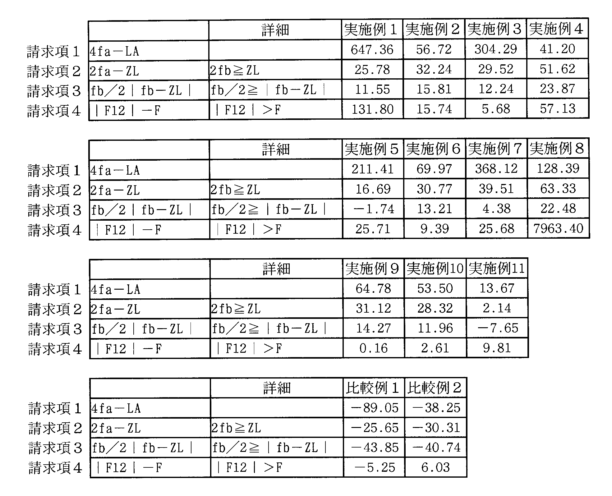
下記表1~3に示すように、各パラメータを所定値となるように設計した車両用前照灯(実施例1~実施例11、比較例1~比較例2)を用いて光源を照射した場合の性能をシミュレーションした結果を、下記表4に示す。
一般に光軸zを中心にした回転対称な多項式非球面の式は下記の数1で表せる。

zは曲率のサグ量、yは光軸からの高さ、Rはyz平面内での曲率半径、κはコーニック係数を表す。
上記式において、y4乗以上の非球面係数A,B,C,D,・・・が0の場合、下記の数2で表せる。

数2を変形すると、下式になる。
y2-2Rz+(1+κ)z2=0
ここで、R/(1+κ)=a、R/(1+κ)1/2=bとおき(κ>-1)、zにZ+aを代入して式変形すると、下記の数3で表せる。
ここで、R/(1+κ)=a、R/(1+κ)1/2=bとおき(κ>-1)、zにZ+aを代入して式変形すると、下記の数3で表せる。

また、κ<-1のときは、下記の数4で表せる。

このとき、反射鏡における焦点は下記の如くなる。
1.楕円のとき
二次元の楕円を考えると、楕円の中心(長軸と短軸の交点)から(a2-b2)1/2離れた位置に二つの焦点を有する。
2.双曲面のとき
二次元の双曲線を考えると、双曲線の中心(双曲線の二つの漸近線の交点)から(a2+b2)1/2離れた位置に二つの焦点を有する。
1.楕円のとき
二次元の楕円を考えると、楕円の中心(長軸と短軸の交点)から(a2-b2)1/2離れた位置に二つの焦点を有する。
2.双曲面のとき
二次元の双曲線を考えると、双曲線の中心(双曲線の二つの漸近線の交点)から(a2+b2)1/2離れた位置に二つの焦点を有する。
以上、これを満たすa,bの値を表1~3に記載する。
3.その他の曲面のとき
二次元的に考えたとき、その曲線の近軸近傍における曲率半径をRとすると、頂点からR/2離れた位置に焦点を有する。
3.その他の曲面のとき
二次元的に考えたとき、その曲線の近軸近傍における曲率半径をRとすると、頂点からR/2離れた位置に焦点を有する。
また、光軸zに対してそれに直交する方向をx,yとすると、バイコーニック面の記述式は下記の数5で表せる。
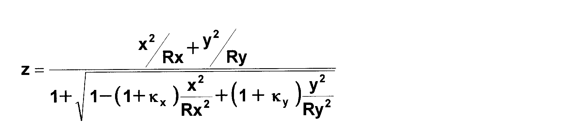
但し、Rx:x方向曲率半径、Ry:y方向曲率半径、kx:x方向のコーニック係数、ky:y方向のコーニック係数である。
xy多項式面の式は下記の数6で表せる。

但し、N:多項式係数の個数、Ai:i番目の項の係数である。
そして、このときの各実施例及び比較例において以下に示す設計性能の評価を行った。

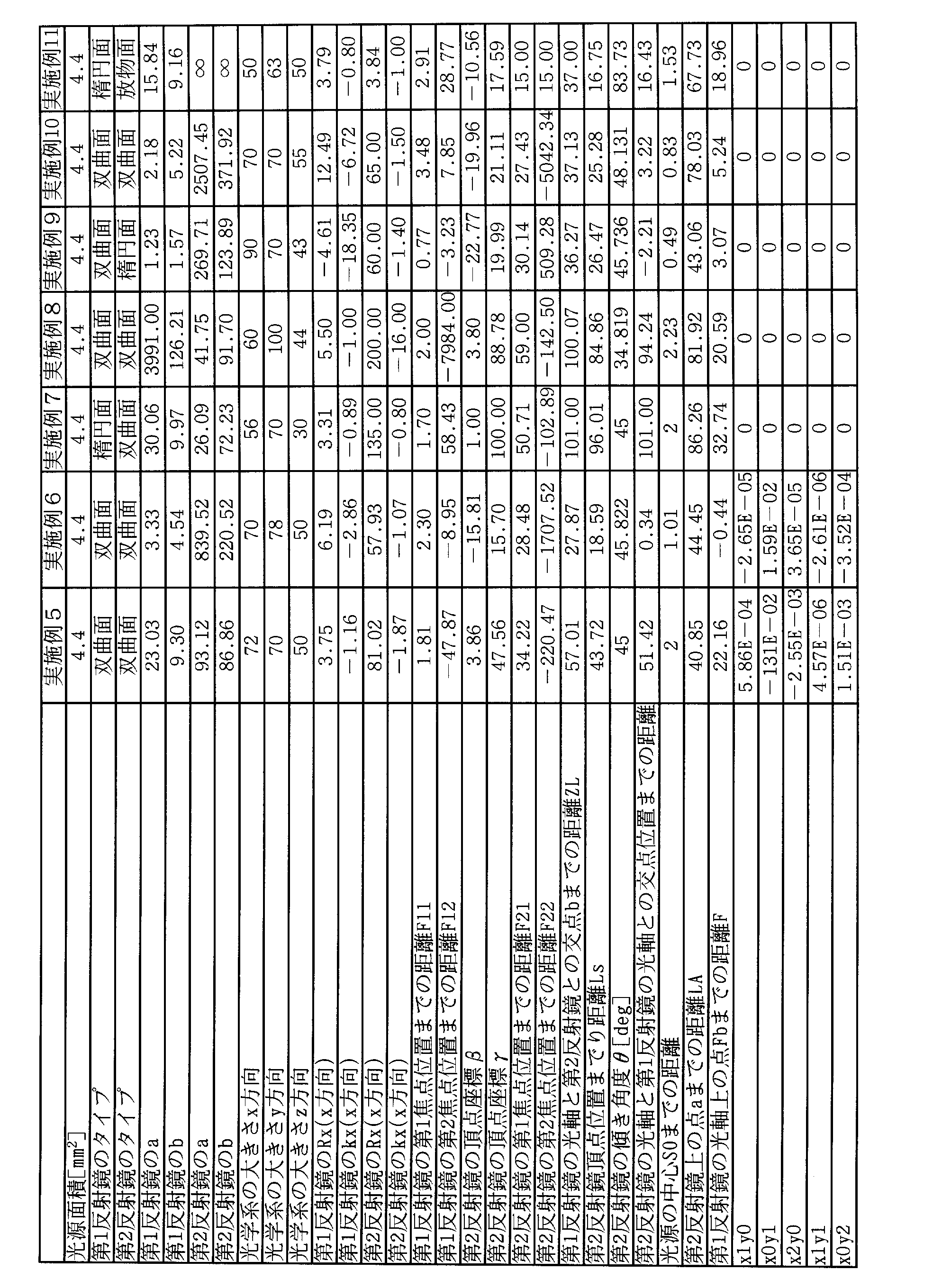
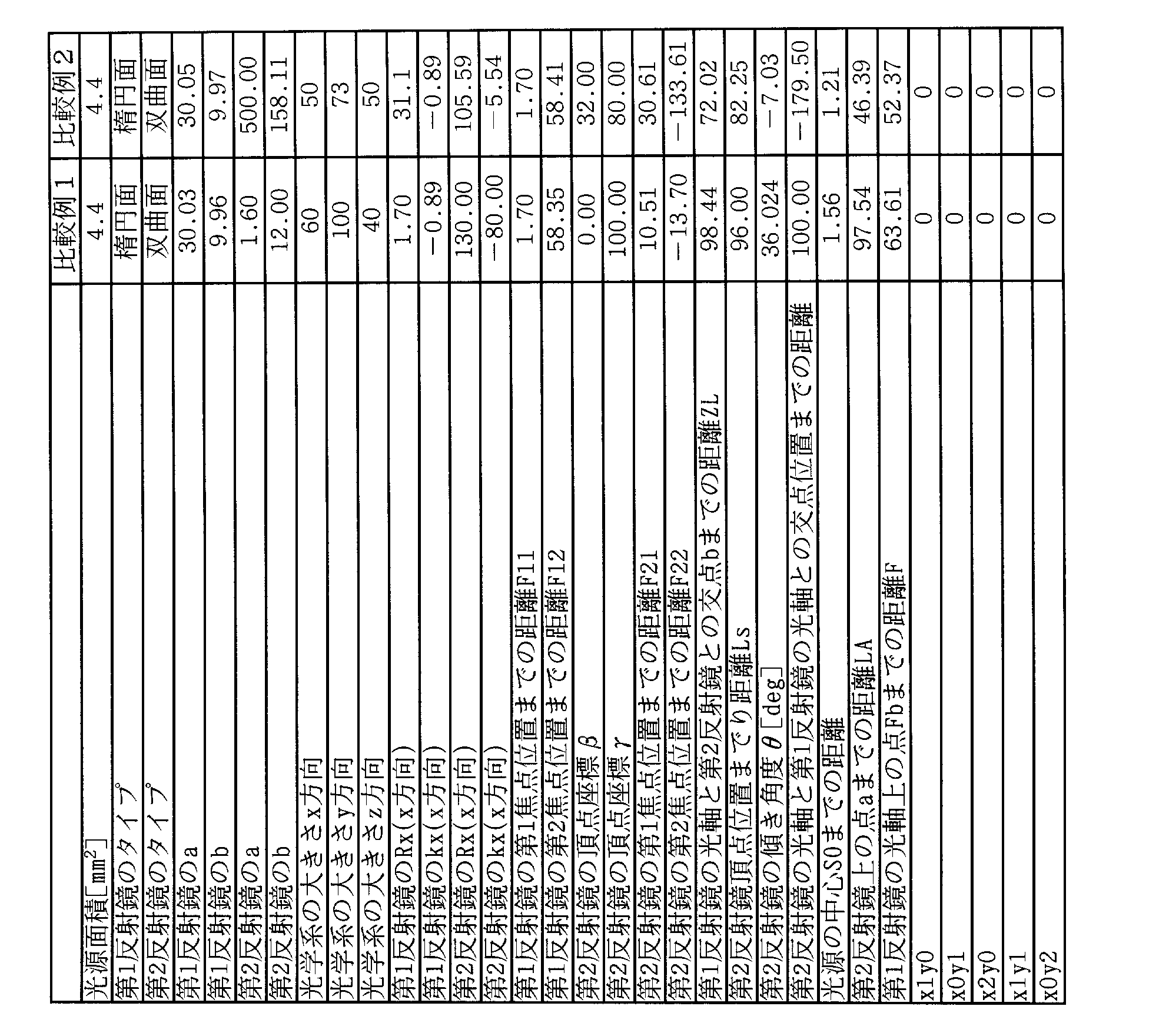
なお、表1~3に示す第2反射鏡の頂点座標(β,γ)は、x軸方向をα方向、第1反射鏡の光軸A1方向をγ方向にとり座標の原点をxyz座標系と一致させた(P1を原点とした)、αβγの直交座標系における座標位置を示す。つまり、xyz座標系を第1反射鏡の光軸A1とy軸との成す角φだけx軸周りにz→y方向に回転させ、x→α,y→γ,z→βとした時に作られる座標系における座標位置を示す。
なお実施例4、7~11及び比較例1,2はバイコーニック面、実施例2、3、5、6はxy多項式面である。また、実施例6は、図4のような遮光板をx軸のプラス方向にのみ(第1反射鏡の光軸A1に対して非対称になるように)挿入した。
[小型化]
小型化の尺度として、発光面の面積に対する光学系が占める体積の比Rを用い、各実施例及び比較例についてRの値を求めた。Rは以下のようにして算出し、その結果を表3に示した。
小型化の尺度として、発光面の面積に対する光学系が占める体積の比Rを用い、各実施例及び比較例についてRの値を求めた。Rは以下のようにして算出し、その結果を表3に示した。
R=V/S[mm]
S:発光面の面積[mm2]
V:光学系の体積[mm3](光学系の体積は、光学系の水平方向の最大長さ×鉛直方向の最大長さ×車両進行方向の最大長さ)
現行の白色LEDを用いた車両用前照灯では、S=3[mm2]、V=1200000[mm3](水平方向の最大長さ:200[mm]、鉛直方向の最大長さ:60[mm]、車両進行方向の最大長さ:100[mm])程度が一般的であり、R=400000[mm]となる。本発明では、この6.4分の1であるR<62500の場合を小型の光学系と定義する。これは、S=4[mm2]に対し、V<250000[mm3](水平方向の最大長さ:100[mm]、鉛直方向の最大長さ:50[mm]、車両進行方向の最大長さ[50mm]に相当する。
[高性能]
白色LED光源の発光面積に対して小型な光学系でありながら高性能であるという点については、下記の尺度ηを用い、各実施例及び比較例についてηの値を求めた。ηは以下のようにして算出し、その結果を表3に示した。ここで一般的に要求される性能を満たすためにはη>1.0E-5(E-5は10-5を表す)であることが好ましい。
S:発光面の面積[mm2]
V:光学系の体積[mm3](光学系の体積は、光学系の水平方向の最大長さ×鉛直方向の最大長さ×車両進行方向の最大長さ)
現行の白色LEDを用いた車両用前照灯では、S=3[mm2]、V=1200000[mm3](水平方向の最大長さ:200[mm]、鉛直方向の最大長さ:60[mm]、車両進行方向の最大長さ:100[mm])程度が一般的であり、R=400000[mm]となる。本発明では、この6.4分の1であるR<62500の場合を小型の光学系と定義する。これは、S=4[mm2]に対し、V<250000[mm3](水平方向の最大長さ:100[mm]、鉛直方向の最大長さ:50[mm]、車両進行方向の最大長さ[50mm]に相当する。
[高性能]
白色LED光源の発光面積に対して小型な光学系でありながら高性能であるという点については、下記の尺度ηを用い、各実施例及び比較例についてηの値を求めた。ηは以下のようにして算出し、その結果を表3に示した。ここで一般的に要求される性能を満たすためにはη>1.0E-5(E-5は10-5を表す)であることが好ましい。
η=光学系の効率/R
光学系の効率=前方への出射光[Lumen]/光源からの出射光[Lumen]
前方:車両進行方向から水平方向に±25°以内、鉛直方向で-10°~10°以内とする(図7参照)。
光学系の効率=前方への出射光[Lumen]/光源からの出射光[Lumen]
前方:車両進行方向から水平方向に±25°以内、鉛直方向で-10°~10°以内とする(図7参照)。

表5の結果より、実施例1~実施例11は、比較例1~比較例2に比べて小型化及び高性能の両立を図れることがわかる。
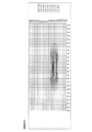
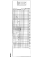
さらに、図8(a),(b)に示すように、実施例1~実施例11及び比較例1~比較例2の車両用前照灯から前方に10m離れた位置に、路面に垂直となるように仮想的なスクリーンを設け、車両用前照灯で照射した場合のシミュレーションを行なった。光源にはランバート分布のLEDを想定してシミュレーションを行った。このときの出射光の照度分布[lx]を図9~図21に示した。図9~図21の図において、横軸は水平方向距離[mm]、縦軸は鉛直方向距離[mm]を表す。なお、図の照度分布は1つの車両用前照灯を使用した場合である。
照度分布が良好な条件(実施例の条件)とは、(i)400lumenの光源で、(ii)光源位置から10m先のスクリーン上において最も強い中心照度100lx以上、(iii)ホットスポットが無い(最も照度の強い箇所が2つ以上無い)、(iv)y軸方向にダラダラと広がっていないことである。
図9~図21の結果より、実施例1~実施例11は、比較例1~比較例2に比べて明らかに照度分布が優れ、高性能であることが認められる。
1 第1反射鏡
2 光源
3 第2反射鏡
100 車両用前照灯
A1 第1反射鏡の光軸
A2 第2反射鏡の光軸
P1 第1反射鏡の頂点
P2 第2反射鏡の頂点
f11 第1反射鏡の第1焦点
f12 第1反射鏡の第2焦点
a 主光線が第1反射鏡で反射され、第2反射鏡に入射する第2反射鏡上の点
b 第1交点
Fb 第2交点
S0 光源中心
2 光源
3 第2反射鏡
100 車両用前照灯
A1 第1反射鏡の光軸
A2 第2反射鏡の光軸
P1 第1反射鏡の頂点
P2 第2反射鏡の頂点
f11 第1反射鏡の第1焦点
f12 第1反射鏡の第2焦点
a 主光線が第1反射鏡で反射され、第2反射鏡に入射する第2反射鏡上の点
b 第1交点
Fb 第2交点
S0 光源中心
Claims (12)
- 面発光の光源と、
第1反射鏡と、
第2反射鏡と、を有し、
前記第1反射鏡の頂点を原点として車両進行方向に向かってz軸を取り、それに直交する水平方向をx軸、鉛直方向をy軸とした際に、
yz平面内において、
前記第1反射鏡の曲率中心側に前記光源が設けられ、
x軸と前記第1反射鏡の光軸とで構成される平面に対して垂直な方向に、前記光源の中心から出射した光線を主光線とし、
前記主光線が前記第1反射鏡で反射され、前記第2反射鏡に入射する前記第2反射鏡上の点をaとし、
前記光源の中心から、前記第2反射鏡上の点aまでの距離をLAとし、
前記第1反射鏡及び前記第2反射鏡によって反射された前記主光線に対する光学系の合成焦点距離をfaとすると、下記式(1)を満たすことを特徴とする車両用前照灯。
4fa≧LA・・・式(1)
前記第1反射鏡の光軸とは、
1.前記第1反射鏡に頂点が存在する場合、前記第1反射鏡の頂点に接する接平面に垂直な前記第1反射鏡の頂点を通る軸を前記第1反射鏡の光軸とし、
2.前記第1反射鏡が頂点を含まない曲面の場合、前記光源が乗っている平面とその平面に垂直に交わるz軸を含む面との交線を前記第1反射鏡の光軸とする。
また、このとき、
(a)前記第1反射鏡と前記第1反射鏡の光軸とが交わる場合、その交点を前記第1反射鏡の頂点とし、(b)前記第1反射鏡と前記第1反射鏡の光軸とが交わらない場合、前記第1反射鏡の最も光源に近い側の端点から前記第1反射鏡の光軸に下ろした垂線とが交わる点を前記第1反射鏡の頂点とする。 - 前記光源の中心から、前記第1反射鏡の光軸と前記第2反射鏡とが交わる第1交点までの距離をZLとし、
前記第1交点における前記第2反射鏡の焦点距離をfbとすると、下記式(2)を満たすことを特徴とする請求項1に記載の車両用前照灯。
2fb≧ZL・・・式(2)
ただし、fbは光源側(光の入射側及び出射側)をプラスとする。 - yz平面内において、下記式(3)を満たすことを特徴とする請求項1または2に記載の車両用前照灯。
|fb-ZL|≦fb/2・・・式(3) - 前記第1反射鏡及び前記第2反射鏡のうち少なくとも一方は、x軸方向とそれに垂直なyz平面内の方向とで反射面の形状が異なることを特徴とする請求項1~3のいずれか一項に記載の車両用前照灯。
- 前記第1反射鏡の頂点位置から、前記第1反射鏡の曲率中心側の、前記第1反射鏡の頂点位置に最も近い第1焦点位置までの距離をF11とし、
前記第1反射鏡の頂点位置から、前記第1焦点とは異なる第2焦点位置までの距離をF12とし、
前記第1交点から前記第1反射鏡側にfbだけ離れた、前記第1反射鏡の光軸上の点を第2交点とし、
前記第1反射鏡の頂点位置から、前記第2交点までの距離をFとすると、下記式(4)を満たすことを特徴とする請求項1~4のいずれか一項に記載の車両用前照灯。
|F12|>F・・・式(4) - 前記第1反射鏡の光軸方向の長さをLとすると、下記式(5)を満たすことを特徴とする請求項1~5のいずれか一項に記載の車両用前照灯。
L≦3(mm)・・・式(5) - 車両進行方向における前記第1反射鏡と前記第2反射鏡との間に、遮光部材が配置されていることを特徴とする請求項1~6のいずれか一項に記載の車両用前照灯。
- 車両進行方向における前記第1反射鏡と前記第2反射鏡との間に、反射板が配置されていることを特徴とする請求項1~7のいずれか一項に記載の車両用前照灯。
- 前記第1反射鏡及び前記第2反射鏡のうち少なくとも一方は、多項式非球面であることを特徴とする請求項1~8のいずれか一項に記載の車両用前照灯。
- 前記光源は、半導体発光素子又は有機EL素子であることを特徴とする請求項1~9のいずれか一項に記載の車両用前照灯。
- 前記第1反射鏡及び前記第2反射鏡のうち少なくとも一方は、x軸に関してx軸方向に非対称であることを特徴とする請求項1~10のいずれか一項に記載の車両用前照灯。
- 前記光源は、x軸に関してx軸方向に非対称であることを特徴とする請求項1~11のいずれか一項に記載の車両用前照灯。
Priority Applications (1)
| Application Number | Priority Date | Filing Date | Title |
|---|---|---|---|
| JP2011547454A JPWO2011077947A1 (ja) | 2009-12-24 | 2010-12-08 | 車両用前照灯 |
Applications Claiming Priority (2)
| Application Number | Priority Date | Filing Date | Title |
|---|---|---|---|
| JP2009292310 | 2009-12-24 | ||
| JP2009-292310 | 2009-12-24 |
Publications (1)
| Publication Number | Publication Date |
|---|---|
| WO2011077947A1 true WO2011077947A1 (ja) | 2011-06-30 |
Family
ID=44195481
Family Applications (1)
| Application Number | Title | Priority Date | Filing Date |
|---|---|---|---|
| PCT/JP2010/071982 Ceased WO2011077947A1 (ja) | 2009-12-24 | 2010-12-08 | 車両用前照灯 |
Country Status (2)
| Country | Link |
|---|---|
| JP (1) | JPWO2011077947A1 (ja) |
| WO (1) | WO2011077947A1 (ja) |
Cited By (3)
| Publication number | Priority date | Publication date | Assignee | Title |
|---|---|---|---|---|
| WO2012176652A1 (ja) * | 2011-06-21 | 2012-12-27 | コニカミノルタアドバンストレイヤー株式会社 | 車両用前照灯 |
| WO2012176653A1 (ja) * | 2011-06-21 | 2012-12-27 | コニカミノルタアドバンストレイヤー株式会社 | 車両用前照灯 |
| JP2021508164A (ja) * | 2017-10-10 | 2021-02-25 | ノルディック ライツ エルティーディー. | 作業用ライト |
Citations (2)
| Publication number | Priority date | Publication date | Assignee | Title |
|---|---|---|---|---|
| JP2006127856A (ja) * | 2004-10-27 | 2006-05-18 | Koito Mfg Co Ltd | 車両用照明灯具 |
| JP2007280959A (ja) * | 2006-04-06 | 2007-10-25 | Valeo Vision | 自動車のライトのヘッドランプのための照明モジュール、およびこのタイプのモジュールを備えたヘッドランプ |
-
2010
- 2010-12-08 WO PCT/JP2010/071982 patent/WO2011077947A1/ja not_active Ceased
- 2010-12-08 JP JP2011547454A patent/JPWO2011077947A1/ja active Pending
Patent Citations (2)
| Publication number | Priority date | Publication date | Assignee | Title |
|---|---|---|---|---|
| JP2006127856A (ja) * | 2004-10-27 | 2006-05-18 | Koito Mfg Co Ltd | 車両用照明灯具 |
| JP2007280959A (ja) * | 2006-04-06 | 2007-10-25 | Valeo Vision | 自動車のライトのヘッドランプのための照明モジュール、およびこのタイプのモジュールを備えたヘッドランプ |
Cited By (5)
| Publication number | Priority date | Publication date | Assignee | Title |
|---|---|---|---|---|
| WO2012176652A1 (ja) * | 2011-06-21 | 2012-12-27 | コニカミノルタアドバンストレイヤー株式会社 | 車両用前照灯 |
| WO2012176653A1 (ja) * | 2011-06-21 | 2012-12-27 | コニカミノルタアドバンストレイヤー株式会社 | 車両用前照灯 |
| JP2021508164A (ja) * | 2017-10-10 | 2021-02-25 | ノルディック ライツ エルティーディー. | 作業用ライト |
| US11162660B2 (en) | 2017-10-10 | 2021-11-02 | Nordic Lights Ltd. | Working light |
| JP7065281B2 (ja) | 2017-10-10 | 2022-05-12 | ノルディック ライツ エルティーディー. | 作業用ライト |
Also Published As
| Publication number | Publication date |
|---|---|
| JPWO2011077947A1 (ja) | 2013-05-02 |
Similar Documents
| Publication | Publication Date | Title |
|---|---|---|
| JP4089866B2 (ja) | 投光ユニットおよび該投光ユニットを具備するled車両用照明灯具 | |
| JP4138586B2 (ja) | 光源用ledランプおよびこれを用いた車両用前照灯 | |
| KR101847932B1 (ko) | 발광모듈 | |
| EP2484964B1 (en) | Lamp unit | |
| EP2322848B1 (en) | Vehicle light | |
| CN101023296A (zh) | 具有非对称准直器的led准直器元件 | |
| US9657913B2 (en) | Vehicle lamp module | |
| CN104296044B (zh) | 一种基于衍射元件的rgb激光车灯 | |
| CN109642707A (zh) | 光源装置 | |
| JP5444046B2 (ja) | 車両用前照灯 | |
| CN210740276U (zh) | 一种近光反射型前照灯模组和车辆 | |
| WO2024093061A1 (zh) | 反射式光学模组及使用其的照明装置及车辆 | |
| JP2011134548A (ja) | 車両用前照灯 | |
| CN104279481B (zh) | 车用灯具及包括该车用灯具的车辆 | |
| WO2011077947A1 (ja) | 車両用前照灯 | |
| Dross et al. | LED headlight architecture that creates a high quality beam pattern independent of LED shortcomings | |
| JP2010129322A (ja) | 車両用灯具 | |
| TW201736773A (zh) | 光源模組及其配光方法、以及車燈裝置 | |
| CN210662689U (zh) | 反射型前照灯模组、前照灯及车辆 | |
| WO2011078008A1 (ja) | 車両用前照灯 | |
| KR101756413B1 (ko) | 발광모듈 | |
| US20260123159A1 (en) | Light emitting diode package and apparatus including the same | |
| JP4182126B2 (ja) | 投影型ledランプ | |
| JP4471399B2 (ja) | Ledランプ | |
| JP2014220209A (ja) | 光源装置 |
Legal Events
| Date | Code | Title | Description |
|---|---|---|---|
| 121 | Ep: the epo has been informed by wipo that ep was designated in this application |
Ref document number: 10839181 Country of ref document: EP Kind code of ref document: A1 |
|
| WWE | Wipo information: entry into national phase |
Ref document number: 2011547454 Country of ref document: JP |
|
| NENP | Non-entry into the national phase |
Ref country code: DE |
|
| 122 | Ep: pct application non-entry in european phase |
Ref document number: 10839181 Country of ref document: EP Kind code of ref document: A1 |