WO2011077626A1 - Roll angle estimation device and transport equipment - Google Patents
Roll angle estimation device and transport equipment Download PDFInfo
- Publication number
- WO2011077626A1 WO2011077626A1 PCT/JP2010/006588 JP2010006588W WO2011077626A1 WO 2011077626 A1 WO2011077626 A1 WO 2011077626A1 JP 2010006588 W JP2010006588 W JP 2010006588W WO 2011077626 A1 WO2011077626 A1 WO 2011077626A1
- Authority
- WO
- WIPO (PCT)
- Prior art keywords
- roll angle
- estimation
- angular velocity
- speed
- offset error
- Prior art date
Links
Images


Classifications
-
- B—PERFORMING OPERATIONS; TRANSPORTING
- B60—VEHICLES IN GENERAL
- B60W—CONJOINT CONTROL OF VEHICLE SUB-UNITS OF DIFFERENT TYPE OR DIFFERENT FUNCTION; CONTROL SYSTEMS SPECIALLY ADAPTED FOR HYBRID VEHICLES; ROAD VEHICLE DRIVE CONTROL SYSTEMS FOR PURPOSES NOT RELATED TO THE CONTROL OF A PARTICULAR SUB-UNIT
- B60W40/00—Estimation or calculation of non-directly measurable driving parameters for road vehicle drive control systems not related to the control of a particular sub unit, e.g. by using mathematical models
- B60W40/10—Estimation or calculation of non-directly measurable driving parameters for road vehicle drive control systems not related to the control of a particular sub unit, e.g. by using mathematical models related to vehicle motion
- B60W40/112—Roll movement
-
- B—PERFORMING OPERATIONS; TRANSPORTING
- B62—LAND VEHICLES FOR TRAVELLING OTHERWISE THAN ON RAILS
- B62J—CYCLE SADDLES OR SEATS; AUXILIARY DEVICES OR ACCESSORIES SPECIALLY ADAPTED TO CYCLES AND NOT OTHERWISE PROVIDED FOR, e.g. ARTICLE CARRIERS OR CYCLE PROTECTORS
- B62J45/00—Electrical equipment arrangements specially adapted for use as accessories on cycles, not otherwise provided for
- B62J45/40—Sensor arrangements; Mounting thereof
- B62J45/41—Sensor arrangements; Mounting thereof characterised by the type of sensor
- B62J45/415—Inclination sensors
- B62J45/4151—Inclination sensors for sensing lateral inclination of the cycle
-
- B—PERFORMING OPERATIONS; TRANSPORTING
- B60—VEHICLES IN GENERAL
- B60W—CONJOINT CONTROL OF VEHICLE SUB-UNITS OF DIFFERENT TYPE OR DIFFERENT FUNCTION; CONTROL SYSTEMS SPECIALLY ADAPTED FOR HYBRID VEHICLES; ROAD VEHICLE DRIVE CONTROL SYSTEMS FOR PURPOSES NOT RELATED TO THE CONTROL OF A PARTICULAR SUB-UNIT
- B60W50/00—Details of control systems for road vehicle drive control not related to the control of a particular sub-unit, e.g. process diagnostic or vehicle driver interfaces
- B60W2050/0001—Details of the control system
- B60W2050/0043—Signal treatments, identification of variables or parameters, parameter estimation or state estimation
- B60W2050/0052—Filtering, filters
- B60W2050/0054—Cut-off filters, retarders, delaying means, dead zones, threshold values or cut-off frequency
- B60W2050/0056—Low-pass filters
-
- B—PERFORMING OPERATIONS; TRANSPORTING
- B60—VEHICLES IN GENERAL
- B60W—CONJOINT CONTROL OF VEHICLE SUB-UNITS OF DIFFERENT TYPE OR DIFFERENT FUNCTION; CONTROL SYSTEMS SPECIALLY ADAPTED FOR HYBRID VEHICLES; ROAD VEHICLE DRIVE CONTROL SYSTEMS FOR PURPOSES NOT RELATED TO THE CONTROL OF A PARTICULAR SUB-UNIT
- B60W2300/00—Indexing codes relating to the type of vehicle
- B60W2300/36—Cycles; Motorcycles; Scooters
-
- B—PERFORMING OPERATIONS; TRANSPORTING
- B60—VEHICLES IN GENERAL
- B60W—CONJOINT CONTROL OF VEHICLE SUB-UNITS OF DIFFERENT TYPE OR DIFFERENT FUNCTION; CONTROL SYSTEMS SPECIALLY ADAPTED FOR HYBRID VEHICLES; ROAD VEHICLE DRIVE CONTROL SYSTEMS FOR PURPOSES NOT RELATED TO THE CONTROL OF A PARTICULAR SUB-UNIT
- B60W2520/00—Input parameters relating to overall vehicle dynamics
- B60W2520/10—Longitudinal speed
- B60W2520/105—Longitudinal acceleration
-
- B—PERFORMING OPERATIONS; TRANSPORTING
- B60—VEHICLES IN GENERAL
- B60W—CONJOINT CONTROL OF VEHICLE SUB-UNITS OF DIFFERENT TYPE OR DIFFERENT FUNCTION; CONTROL SYSTEMS SPECIALLY ADAPTED FOR HYBRID VEHICLES; ROAD VEHICLE DRIVE CONTROL SYSTEMS FOR PURPOSES NOT RELATED TO THE CONTROL OF A PARTICULAR SUB-UNIT
- B60W2520/00—Input parameters relating to overall vehicle dynamics
- B60W2520/12—Lateral speed
- B60W2520/125—Lateral acceleration
-
- B—PERFORMING OPERATIONS; TRANSPORTING
- B60—VEHICLES IN GENERAL
- B60W—CONJOINT CONTROL OF VEHICLE SUB-UNITS OF DIFFERENT TYPE OR DIFFERENT FUNCTION; CONTROL SYSTEMS SPECIALLY ADAPTED FOR HYBRID VEHICLES; ROAD VEHICLE DRIVE CONTROL SYSTEMS FOR PURPOSES NOT RELATED TO THE CONTROL OF A PARTICULAR SUB-UNIT
- B60W2520/00—Input parameters relating to overall vehicle dynamics
- B60W2520/14—Yaw
-
- B—PERFORMING OPERATIONS; TRANSPORTING
- B60—VEHICLES IN GENERAL
- B60W—CONJOINT CONTROL OF VEHICLE SUB-UNITS OF DIFFERENT TYPE OR DIFFERENT FUNCTION; CONTROL SYSTEMS SPECIALLY ADAPTED FOR HYBRID VEHICLES; ROAD VEHICLE DRIVE CONTROL SYSTEMS FOR PURPOSES NOT RELATED TO THE CONTROL OF A PARTICULAR SUB-UNIT
- B60W2520/00—Input parameters relating to overall vehicle dynamics
- B60W2520/16—Pitch
-
- B—PERFORMING OPERATIONS; TRANSPORTING
- B60—VEHICLES IN GENERAL
- B60W—CONJOINT CONTROL OF VEHICLE SUB-UNITS OF DIFFERENT TYPE OR DIFFERENT FUNCTION; CONTROL SYSTEMS SPECIALLY ADAPTED FOR HYBRID VEHICLES; ROAD VEHICLE DRIVE CONTROL SYSTEMS FOR PURPOSES NOT RELATED TO THE CONTROL OF A PARTICULAR SUB-UNIT
- B60W2520/00—Input parameters relating to overall vehicle dynamics
- B60W2520/18—Roll
-
- B—PERFORMING OPERATIONS; TRANSPORTING
- B60—VEHICLES IN GENERAL
- B60Y—INDEXING SCHEME RELATING TO ASPECTS CROSS-CUTTING VEHICLE TECHNOLOGY
- B60Y2200/00—Type of vehicle
- B60Y2200/10—Road Vehicles
- B60Y2200/12—Motorcycles, Trikes; Quads; Scooters
Definitions
- the present invention relates to a roll angle estimation device and a transport device including the roll angle estimation device.
- various estimation devices for estimating a roll angle of a vehicle such as a motorcycle have been proposed. For example, by controlling the direction of the headlight based on the roll angle estimated by the estimation device, the headlight can irradiate light in an appropriate direction regardless of the inclination of the vehicle.
- the conventional estimation device cannot estimate the roll angle of the vehicle with high accuracy.
- the direction of the headlight may be inclined.
- An object of the present invention is to provide a roll angle estimation device capable of estimating the roll angle of a moving body with high accuracy and a transport device including the roll angle estimation device.
- a roll angle estimation device is a roll angle estimation device that estimates a roll angle of a moving body, and is a first method around first and second axes along at least two directions.
- First and second angular velocity detectors for detecting first and second angular velocities, respectively, and first, second and third accelerations for detecting first, second and third accelerations in at least three directions, respectively
- a detector, a speed information detector for detecting information on a moving speed of the moving body in a traveling direction, a roll angle of the moving body, a first angular speed detector, a first angular speed detector and a first angular speed detector;
- an estimation unit configured to estimate at least one offset error of the acceleration detectors, wherein the estimation unit includes detection values of the first and second angular velocity detectors, first, second, and third. Acceleration test
- the roll angle of the moving body and at least one offset error are estimated based on the detected value of the detector, the detected value of the speed information detector, the estimated value of the roll angle
- the first and second angular velocity detectors detect the first and second angular velocities around the first and second axes along at least two directions, respectively.
- first, second, and third accelerations in at least three directions are detected by the first, second, and third acceleration detectors, respectively.
- information on the moving speed of the moving body in the traveling direction is detected by the speed information detector.
- the roll angle of the moving body is estimated by the estimation unit, and the offset error of the detection value by at least one of the first and second angular velocity detectors and the first, second and third acceleration detectors Is estimated.
- the estimation unit detects the detection values of the first and second angular velocity detectors, the detection values of the first, second and third acceleration detectors, the detection values of the velocity information detector in the current estimation operation,
- the roll angle of the moving body and at least one offset error are estimated based on the estimated value of the roll angle by the previous estimation operation and the estimated value of the offset error by the previous estimation operation.
- the offset error is estimated together with the roll angle, and the estimated value of the offset error is used in the next estimation operation.
- a decrease in the estimation accuracy of the roll angle due to the offset error of at least one of the first and second angular velocity detectors and the first, second and third acceleration detectors is compensated.
- the roll angle can be estimated with high accuracy.
- the first and second angular velocity detectors detect the first and second angular velocities around the first and second axes along different directions, respectively.
- the three acceleration detectors may detect first, second, and third accelerations in first, second, and third directions different from each other.
- the first and second angular velocities around the first and second axes along different directions are detected by the first and second angular velocity detectors, respectively.
- the first, second and third accelerations in the first, second and third directions different from each other are detected by the first, second and third acceleration detectors, respectively.
- the estimation unit may estimate at least one offset error of the first and second angular velocity detectors as at least one offset error.
- An angular velocity detector is more likely to cause an offset error than an acceleration detector. Therefore, by using the estimated value of the offset error of at least one of the first and second angular velocity detectors in the next estimation operation, the roll angle estimation accuracy is sufficiently improved.
- the estimation unit may estimate the offset errors of the first and second angular velocity detectors as at least one offset error.
- the estimation accuracy of the roll angle is further improved by using the estimated values of the offset errors of the first and second angular velocity detectors in the next estimation operation.
- the estimation unit may further estimate at least one offset error of the first, second, and third acceleration detectors as at least one offset error.
- the estimated value of the offset error of at least one of the first and second angular velocity detectors is used as the next estimating operation.
- the estimation accuracy of the roll angle is further improved.
- the first acceleration is an acceleration in the vertical direction of the moving body, and the estimation unit may estimate the offset error of the first acceleration detector.
- the vertical acceleration of the moving body hardly changes.
- the influence of the change in the detected value of the vertical acceleration becomes large when the roll angle is estimated. Therefore, by using the estimated value of the offset error of the first acceleration detector in the next estimation operation, the estimation accuracy in the range where the roll angle is small is further improved.
- the moving body has a front wheel and a rear wheel
- the speed information detector includes a rear wheel rotation speed detector that detects the rotation speed of the rear wheel as information
- the estimation unit determines the moving speed of the moving body.
- the detection value of the first and second angular velocity detectors, the detection value of the first, second and third acceleration detectors, and the detection value of the rear wheel velocity detector are configured to be estimated. Based on the estimated value of the roll angle by the previous estimation operation, the estimated value of the offset error by the previous estimation operation, and the estimated value of the moving speed by the previous estimation operation, at least one offset error and the movement of the moving body The moving speed of the body may be estimated.
- the moving speed of the moving body can be estimated based on the detected value of the rotational speed of the rear wheel and the estimated value of the roll angle. Therefore, in the current estimation operation, the detection value of the first and second angular velocity detectors, the detection value of the first, second and third acceleration detectors, the detection value of the rotational speed of the rear wheel, and the previous estimation operation Estimate the roll angle, at least one offset error and the moving speed of the moving body based on the estimated roll angle, the estimated offset error value from the previous estimating action, and the estimated moving speed value from the previous estimating action. can do.
- the rotational speed of the rear wheel is closer to the moving speed of the moving object than the rotational speed of the front wheel. Therefore, by using the detected value of the rotational speed of the rear wheel, the roll angle of the moving body, at least one offset error, and the moving speed of the moving body can be estimated with high accuracy.
- the moving body has a front wheel and a rear wheel, and the speed information detector detects a rotational speed of the rear wheel from a front wheel rotational speed detector that detects the rotational speed of the front wheel and a detection value of the front wheel rotational speed detector.
- a rear wheel rotation speed estimation unit that estimates as information, and the estimation unit is configured to further estimate the moving speed of the moving body, and the detection values of the first and second angular velocity detectors in the current estimation operation, First, second and third acceleration detector detection values, rear wheel speed detector estimation values, roll angle estimation values from previous estimation operations, offset error estimation values from previous estimation operations, and previous estimations
- the roll angle of the moving body, at least one offset error, and the moving speed of the moving body may be estimated based on the estimated value of the moving speed due to the operation.
- the rear wheel rotation speed estimation unit estimates the rear wheel rotation speed from the detection value of the front wheel rotation speed detector. Therefore, even when the front wheel rotation speed detector is provided, the roll angle of the moving body, at least one offset error, and the moving speed of the moving body are increased as in the case where the rear wheel rotation speed detector is provided. It is possible to estimate with accuracy.
- the estimation unit detects the detection values of the first and second angular velocity detectors, the detection values of the first, second, and third acceleration detectors, the detection value of the velocity information detector, and the previous time
- a Kalman filter that estimates the roll angle of the moving body and at least one offset error using the relationship between the estimated value of the roll angle by the previous estimation operation and the estimated value of the offset error by the previous estimation operation may be included.
- the estimation unit can be easily realized by using the Kalman filter algorithm.
- a transportation device is estimated by a movable body configured to be movable, a roll angle estimation device according to the invention that estimates a roll angle of the movable body, and a roll angle estimation device. And a processing unit that performs processing using a roll angle.
- the roll angle of the moving part is estimated with high accuracy by the roll angle estimation device according to the invention. Thereby, the process using the roll angle by the processing unit is performed with high accuracy.
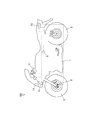
- FIG. 1 is a schematic diagram of a vehicle provided with a roll angle estimation device according to an embodiment of the present invention.
- FIG. 2 is a block diagram showing a configuration of the roll angle estimation apparatus according to the embodiment of the present invention.
- FIG. 3 is a diagram showing the concept of the Kalman filter.
- FIG. 4 is a diagram for explaining the mounting position of the sensor group.
- FIG. 5 is a cross-sectional view of the rear wheel.
- FIG. 6 is a vector representation of the mounting position of the sensor group.
- FIG. 7 is a diagram showing the time transition of the estimated values of the parameters by the roll angle estimating device.
- FIG. 8 is a diagram showing the time transition of the estimated values of the parameters.
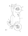
- FIG. 1 is a schematic diagram of a vehicle provided with a roll angle estimation device according to an embodiment of the present invention.
- FIG. 2 is a block diagram showing a configuration of the roll angle estimation apparatus according to the embodiment of the present invention.
- FIG. 3 is a diagram showing the concept of
- FIG. 9 is a schematic diagram of a vehicle provided with a roll angle estimation device according to another embodiment of the present invention.
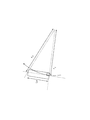
- FIG. 10 is a diagram showing the turning radii of the front wheels and the rear wheels when the vehicle is turning.
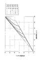
- FIG. 11 is a diagram showing a calculation result of the relationship between the front wheel speed and the rear wheel speed.
- FIG. 1 is a schematic diagram of a vehicle provided with a roll angle estimation device according to an embodiment of the present invention.
- the vehicle 100 in FIG. 1 is a motorcycle.
- the vehicle 100 includes a vehicle body 1.
- a front wheel 2 is attached to the front portion of the vehicle body 1, and a rear wheel 3 is attached to the rear portion of the vehicle body 1.
- a sensor group 5 is attached to the center of the vehicle body 1. Details of the sensor group 5 will be described later.
- a rear wheel speed sensor 7 for detecting the rotation speed of the rear wheel 3 is attached to the wheel of the rear wheel 3.
- a handle 11 is provided at the upper part on the front side of the vehicle body 1 so as to be able to swing left and right.
- a navigation system 12 is provided in the vicinity of the handle 11.
- a headlight 14 and a headlight driving device 15 are provided at the front of the vehicle body 1.
- the headlight driving device 15 controls the direction of the headlight 14.
- An electronic control unit (hereinafter abbreviated as ECU) 20 is provided at the rear portion of the vehicle body 1.
- Output signals of the sensor group 5 and the rear wheel speed sensor 7 are given to the ECU 20.
- ECU20 controls each part of the vehicle body 1, estimates the roll angle of the vehicle body 1, and gives the estimated roll angle to the navigation system 12 and the headlight drive device 15, for example.
- the sensor group 5, the rear wheel speed sensor 9 and the ECU 20 constitute a roll angle estimating device.
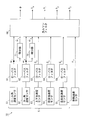
- FIG. 2 is a block diagram showing the configuration of the roll angle estimation device according to one embodiment of the present invention.
- Kalman filter 80 includes a sensor group 5, a rear wheel speed sensor 7, low-pass filters 61 to 65, differentiators 71 and 72, and a Kalman filter 80.
- the function of the Kalman filter 80 is realized by the ECU 20 and the program of FIG.
- Sensor group 5 includes roll angular velocity sensor 51, yaw angular velocity sensor 52, vertical acceleration sensor 53, longitudinal acceleration sensor 54, and lateral acceleration sensor 55.
- the roll angular velocity sensor 51 is provided in the vehicle body 1 so as to detect the roll angular velocity of the vehicle body 1.
- the roll angular velocity is an angular velocity around the longitudinal axis of the vehicle 100.
- the yaw angular velocity sensor 52 is provided in the vehicle body 1 so as to detect the yaw angular velocity of the vehicle body 1.
- the yaw angular velocity is an angular velocity around the vertical axis of the vehicle 100.
- the vertical acceleration sensor 53 is provided on the vehicle body 1 so as to detect the vertical acceleration of the vehicle body 1.
- the vertical acceleration is the vertical acceleration of the vehicle body 1.
- the longitudinal acceleration sensor 54 is provided in the vehicle body 1 so as to detect the longitudinal acceleration of the vehicle body 1.
- the longitudinal acceleration is an acceleration in the longitudinal direction of the vehicle body 1.
- the lateral acceleration sensor 55 is provided in the vehicle body 1 so as to detect the lateral acceleration of the vehicle body 1.
- the lateral acceleration is the lateral acceleration of the vehicle body 1.
- the output signal of the roll angular velocity sensor 51 is given to the Kalman filter 80 and the differentiator 71 as the roll angular velocity through the low pass filter 61.
- the low pass filter 61 removes noise from the output signal of the roll angular velocity sensor 51.
- the differentiator 71 gives a differential value of the roll angular velocity to the Kalman filter 80 as roll angular acceleration.
- the output signal of the yaw angular velocity sensor 52 is given to the Kalman filter 80 and the differentiator 72 as the yaw angular velocity through the low pass filter 62.
- the low-pass filter 62 removes noise from the output signal of the yaw angular velocity sensor 52.
- the differentiator 72 gives the differential value of the yaw angular velocity to the Kalman filter 80 as the yaw angular acceleration.
- the output signal of the vertical acceleration sensor 53 is given to the Kalman filter 80 as the vertical acceleration through the low pass filter 63.
- the output signal of the longitudinal acceleration sensor 54 is given to the Kalman filter 80 as the longitudinal acceleration through the low pass filter 64.
- the output signal of the lateral acceleration sensor 55 is given to the Kalman filter 80 as lateral acceleration through the low pass filter 65.
- the output signal of the rear wheel speed sensor 7 is given to the Kalman filter 80 as the rear wheel speed.
- the rear wheel speed is the rotational speed of the outermost periphery of the tire when it is assumed that no slip occurs between the road surface and the tire of the rear wheel 3.
- the output signal of the rear wheel speed sensor 7 and the size of the tire Is calculated based on In order to simplify the explanation, it is assumed that a signal indicating the rear wheel speed is output from the rear wheel speed sensor 7 in FIG.
- roll angular velocity, roll angular acceleration, yaw angular velocity, yaw angular acceleration, vertical acceleration, longitudinal acceleration, lateral acceleration, and rear wheel velocity are represented by the symbols in the table below.
- symbol showing each parameter means a 1st-order differentiation.
- the Kalman filter 80 estimates and outputs the roll angle, vehicle speed, roll angular velocity sensor offset, yaw angular velocity sensor offset, and vertical acceleration sensor offset based on the above parameters.
- a vertical plane parallel to the traveling direction of the vehicle 100 is referred to as a front-rear vertical plane
- a vertical plane perpendicular to the front-rear vertical plane is referred to as a left-right vertical plane.
- the roll angle is an inclination angle of the vehicle body 1 with respect to the direction of gravity in the left and right vertical plane.
- the vehicle speed is a speed in the traveling direction of the vehicle body 1.
- the roll angular velocity sensor offset is an offset error of the roll angular velocity sensor 51
- the yaw angular velocity sensor offset is an offset error of the yaw angular velocity sensor 52
- the vertical acceleration sensor offset is an offset error of the vertical acceleration sensor 53.
- Vehicle speed, roll angular velocity sensor offset, yaw angular velocity sensor offset, and vertical acceleration sensor offset are represented by the symbols in the table below.
- a roll angular velocity sensor 51 a yaw angular velocity sensor 52, a vertical acceleration sensor 53, a longitudinal acceleration sensor 54, a lateral acceleration sensor 55, and a rear wheel speed sensor 7, which will be described later (
- Five relational expressions 17) and (18) are derived.
- two parameters of the roll angle ⁇ and the vehicle speed V x are estimated. That is, there is redundancy between the number of relational expressions and the estimated number of outputs. In other words, the number of relational expressions is larger than the number of estimated outputs.
- Roll angular rate sensor offset b r by utilizing this redundancy, it is possible to estimate the yaw rate sensor offset b y and the vertical acceleration sensor offset b z.
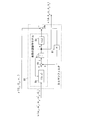
- FIG. 3 is a diagram showing the concept of the Kalman filter 80.
- a kinematic model of the vehicle 100 described below is used.
- the Kalman filter 80 includes a system equation 8a, an addition function 8b, an integration function 8c, an observation equation 8d, a subtraction function 8e, and a Kalman gain 8f.
- the system equation 8a includes a function f (x, u)
- the observation equation 8d includes a function h (x)
- the Kalman gain 8f includes a fifth-order Kalman gain K.
- the detection value of the roll angular velocity omega r As an input parameter u of the system equations 8a, the detection value of the roll angular velocity omega r, the detected value of the roll angular acceleration (differential value of the roll angular velocity omega r), the detection value of the yaw angular velocity omega y, the yaw angular acceleration (The differential value of the yaw angular velocity ⁇ y ) and the detected value of the longitudinal acceleration G x are given.
- the estimated value of the roll angle ⁇ from the previous estimation operation the estimated value of the vehicle speed V x, the estimated value of the roll angular velocity sensor offset b r, estimated value of the yaw angular velocity sensor offset b y and estimated value of the vertical acceleration sensor offset b z is given.
- the output of the system equations 8a is the differential value of the roll angle phi, the differential value of the vehicle speed V x, the differential value of the roll angular velocity sensor offset b r, differentiation of the differential value and the vertical acceleration sensor offset b z of the yaw rate sensor offset b y Value.
- the Kalman filter 80 is provided with a detection value of the vertical acceleration G z, a detection value of the left-right acceleration G y, and a detection value of the rear wheel speed v r as input parameters y.
- the Kalman gain K is calculated based on the difference between the detected value and the calculated value of the vertical acceleration G z , the horizontal acceleration G y, and the rear wheel speed v r .
- the roll angle, roll angle differential value, pitch angle, pitch angle differential value, yaw angle, yaw angle differential value, roll angular velocity, yaw angular velocity, and pitch angular velocity are represented by the following symbols.
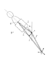
- FIG. 4 is a diagram for explaining the mounting position of the sensor group 5.
- the left side of the vehicle 100 is shown on the left side of FIG. 4, and the front of the vehicle 100 is shown on the right side.
- FIG. 5 is a cross-sectional view of the rear wheel 3.
- FIG. 6 is a vector representation of the mounting position of the sensor group 5.
- the attachment position of the sensor group 5 is PS.
- the horizontal distance from the attachment position PS to the center of the rear wheel 3 is L, and the height from the road surface to the attachment position PS is h.
- the rear wheel 3 is inclined by a roll angle ⁇ with respect to the road surface RD. From the above assumption (d), the road surface RD is not inclined.
- P be the contact point between the tire TR of the rear wheel 3 and the road surface RD.
- the second-order differential vector of the position vector rv the second-order differential vector of the position vector rv 0 , the second-order differential vector of the vector ⁇ v, and the gravitational acceleration vector are represented by the symbols in the following table. Note that the two dots above the sign representing each parameter mean second order differentiation.
- the acceleration vector detected by the vertical acceleration sensor 53, the longitudinal acceleration sensor 54, and the lateral acceleration sensor 55 at the attachment position PS is Gv.
- the acceleration vector Gv is obtained by adding the gravitational acceleration vector to the second derivative vector of the position vector rv as in the following equation.
- [e] [e 1 , e 2 , e 3 ].
- e 1 , e 2, and e 3 are basis vectors fixed to the vehicle body 1
- e 1 is a basis vector in the forward direction of the vehicle body 1
- e 2 is a basis vector in the left direction of the vehicle body 1
- e Reference numeral 3 denotes a base vector in the vertical upward direction of the vehicle body 1.
- ⁇ is a matrix.
- the matrix ⁇ in the above equation (5) is expressed by the following equation from FIGS. 4 and 5.
- a x , a y and a z are functions.
- the functions a x , a y , and a z can be obtained by calculating the above equations (5) and (6).
- the differential value of the roll angle ⁇ and the differential value of the yaw angle ⁇ can be eliminated by using the above formula (3) in the transformation from the above formula (6) to the above formula (7).
- the first-order differential vector of the position vector rv 0 in FIG. 6 is expressed by the following equation using the vehicle speed V x and the skid speed V y .
- [e0] [e0 1 , e0 2 , e0 3 ].
- g is the magnitude of gravitational acceleration.
- the acceleration vector Gv detected at the attachment position PS from the above equations (4), (7), (9), and (10) is expressed as the following equation.
- the acceleration vector Gv detected at the attachment position PS is detected by the longitudinal acceleration G x detected by the longitudinal acceleration sensor 54, the lateral acceleration G y detected by the lateral acceleration sensor 55, and the vertical acceleration sensor 53.
- the vertical acceleration G z is used to express the following equation.
- the extended Kalman filter can be applied by using the above equation (15) as a system equation and the above equation (16) as an observation equation.
- the differential value of the roll angular velocity sensor offset b r, a differential value of the differential value and the vertical acceleration sensor offset b z of the yaw rate sensor offset b y can be regarded as zero.
- the offset error (roll angular velocity sensor offset b r ) of the roll angular velocity sensor 51 and the offset error (yaw angular velocity sensor offset b y ) of the yaw angular velocity sensor 52 are estimated.
- Estimation accuracy of the roll angle ⁇ is sufficiently improved by the use of the estimated value of the roll angular velocity sensor offset b r and the yaw angular velocity sensor offset b y during the next estimation operation.
- the offset error (vertical acceleration sensor offset b z ) of the vertical acceleration sensor 53 is estimated for the following reason. In the range where the roll angle ⁇ of the vehicle body 1 is small, the vertical acceleration of the vehicle body 1 hardly changes. If the detected value of such vertical acceleration is changed by the vertical acceleration sensor offset b z, influence of change in the detected values of vertical acceleration at the time of estimation of the roll angle ⁇ increases. Therefore, by using the estimated value of the vertical acceleration sensor offset b z in the next estimation operation, the estimation accuracy in the range where the roll angle ⁇ is small is further improved.
- FIG. 7 and FIG. 8 are diagrams showing time transition of the estimated value of each parameter when the roll angular velocity sensor 51 has and does not have an offset error.
- a roll angular velocity sensor 51, a yaw angular velocity sensor 52, a vertical acceleration sensor 53, a longitudinal acceleration sensor 54, a lateral acceleration sensor 55, and a rear wheel velocity sensor 7 that do not have an offset error are attached to the vehicle 100, and a roll angular velocity that actually travels is attached.
- estimated values of the respective parameters were calculated.
- an offset error of 3 deg / s was added to the detection value of the roll angular velocity sensor 51, and the estimated value of each parameter was calculated.
- Figure 7 shows an estimate of the roll angle ⁇ and the vehicle speed V x
- Figure 8 shows an estimate of the roll angular velocity sensor offset b r, yaw rate sensor offset b y and the vertical acceleration sensor offset b z.
- Symbol L0 indicates an estimated value of each parameter when no offset is added to the roll angular velocity sensor 51
- Loff indicates an estimated value of each parameter when an offset error is added to the detected value of the roll angular velocity sensor 51.
- the estimated value of the roll angle ⁇ is the roll when the offset error is not added to the detected value of the roll angular velocity sensor 51 in a short time. It agrees with the estimated value of the angle ⁇ . Also, the estimated value of the vehicle speed V x in the case where the offset error is added to the detected value of the roll angular velocity sensor 51, the estimated value of the vehicle speed V x in a case where the detected value of the roll angular velocity sensor 51 is not added offset error It almost matches.
- the roll angular velocity sensor when the detected value of the roll angular velocity sensor offset b estimate of r and the roll angular velocity sensor 51 in the case where the offset error is added to the roll angular velocity sensor 51 detects values not added offset error
- the difference from the estimated value of the offset br becomes equal to the offset error value (3 deg / s).
- the estimated values of the yaw angular velocity sensor offset b y and the vertical acceleration sensor offset b z are substantially zero both when the offset error is not added to the detection value of the roll angular velocity sensor 51 and when it is added.
- the roll angle estimation device 10 it is understood that the roll angle ⁇ can be estimated with high accuracy even when the roll angular velocity sensor 51 has an offset error.
- the roll angle estimating apparatus 10 According to the roll angle estimating apparatus 10 according to the effect the present embodiment of the embodiment, the roll angular velocity with the roll angle ⁇ and the vehicle speed V x sensor offset b r, yaw rate sensor offset b y and the vertical acceleration sensor offset b z is estimated, the roll angular velocity sensor offset b r, estimated value of the yaw angular velocity sensor offset b y and the vertical acceleration sensor offset b z is used when the next estimation operation. Thereby, the roll angular velocity sensor offset b r, decrease in the estimation accuracy of the roll angle ⁇ by the yaw rate sensor offset b y and the vertical acceleration sensor offset b z is compensated. As a result, the roll angle ⁇ can be estimated with high accuracy.
- the estimated offset error values of the roll angular velocity sensor 51 and the yaw angular velocity sensor 52 that are more likely to cause an offset than the acceleration sensor are used for the next estimation operation. Thereby, the estimation accuracy of the roll angle ⁇ is sufficiently improved.
- the estimated value of the offset error of the vertical acceleration sensor 53 is used in the next estimation operation. Thereby, the estimation accuracy in a range where the roll angle ⁇ is small is further improved.
- the detection value of the wheel speed v r after being detected by the rear wheel speed sensor 7 is used for estimation operation. Thereby, even when the vehicle 100 turns at a low speed with a small radius, the roll angle ⁇ , the roll angular velocity sensor offset b r , the yaw angular velocity sensor offset b y , the vertical acceleration sensor offset b z and the vehicle velocity V x of the vehicle body 1 are increased. It is possible to estimate with accuracy.
- the roll angle estimation device 10 estimates the roll angle ⁇ of the vehicle body 1 with high accuracy. Accordingly, the navigation system 12 and the headlight driving device 15 operate accurately based on the roll angle ⁇ estimated by the ECU 20.
- FIG. 9 is a schematic diagram of a vehicle provided with a roll angle estimation device according to another embodiment of the present invention.
- the wheel speed v r after being detected by the rear wheel speed sensor 7 is used, instead of the wheel speed v r after being detected by the rear wheel speed sensor 7, shown in Figure 9
- the rear wheel speed v r may be estimated from the front wheel speed detected by the front wheel speed sensor 6.
- the turning radius of the front wheel 2 is larger than the turning radius of the rear wheel 3.
- the rotational speed of the front wheel 2 detected by the front wheel speed sensor 6 is higher than the rotational speed of the rear wheel 3. Therefore, the rear wheel speed v r can be estimated by the ECU20 from the rotational speed of the front wheel 2 detected by the front wheel speed sensor 6.
- FIG. 10 is a diagram showing turning radii of the front wheels 2 and the rear wheels 3 when the vehicle 100 is turning. Since the above side-slip velocity assumption (c) from the rear wheel 3 of a 0, the following equation of relationship between the turning radius r r of the front wheels 2 turning radius r f and the rear wheel 3 is established.
- La is the wheelbase length of the vehicle 100. From the above equation (19), the following equation is obtained.
- the turning radius r r of the rear wheel 3 is expressed by the following equation using the speed V r of the ground contact point of the rear wheel 3 and the roll angle ⁇ .
- the rear wheel speed v r can be calculated from the rotational speed of the front wheel 2 detected by the front wheel speed sensor 6 (hereinafter referred to as the front wheel speed v f ).
- FIG. 11 is a diagram showing a calculation result of the relationship between the front wheel speed v f and the rear wheel speed v r .
- the horizontal axis in FIG. 10 represents the rear wheel speed v r
- the vertical axis represents the front wheel speed v f .
- the rear wheel speed v r can be estimated from the front wheel speed v f detected by the front wheel speed sensor 6. Accordingly, when only the front wheel speed sensor 6 is provided, the roll angle ⁇ of the vehicle body 1, the vehicle speed V x , the roll angular speed sensor offset b r , and the yaw angular speed sensor are provided as in the case where the rear wheel speed sensor 7 is provided. the offset b y and the vertical acceleration sensor offset b z can be estimated with high accuracy.
- (D) instead of the vertical acceleration sensor 53, the longitudinal acceleration sensor 54, and the lateral acceleration sensor 55 in the above-described embodiment, three or more that detect accelerations in three or more directions different from the vertical direction, the longitudinal direction, and the lateral direction of the vehicle 100
- the acceleration sensor may be used.
- the above equations (17) and (18) can be used.
- the roll angular velocity sensor offset b r and the yaw angular velocity sensor offset b y are estimated by the Kalman filter 80, but the present invention is not limited to this, and only the roll angular velocity sensor offset b r may be estimated. Only yaw rate sensor offset b y may be estimated. When only the roll angular velocity sensor offset br is estimated, the calculation may be performed with other sensor offset values set to zero. Similarly when estimating only the yaw angular velocity sensor offset b y, it is sufficient to calculate the value of other sensors offset zero.
- the vertical acceleration sensor offset b z is estimated.
- the present invention is not limited to this, and the offset error of the longitudinal acceleration sensor 54 may be estimated, or the offset error of the lateral acceleration sensor 55 is It may be estimated.
- the vehicle speed V x is estimated by the Kalman filter 80.
- the vehicle speed V x is not estimated by the Kalman filter 80. Good.
- the Kalman filter 80 is realized by the ECU 20 and the program.
- the present invention is not limited to this, and part or all of the functions of the Kalman filter 80 may be realized by hardware such as an electronic circuit.
- Kalman filter 80 instead of the Kalman filter 80 in the above embodiment, another adaptive filtering method may be used.
- an LMS (least mean square) adaptive filter or H ⁇ filtering may be used.
- the roll angle estimation device 10 is applied to a motorcycle.
- the present invention is not limited to this, and the roll angle estimation device 10 may be another vehicle such as an automobile or a tricycle, a ship, or the like. It can be applied to various transport equipment.
- the roll angle ⁇ estimated by the roll angle estimation device 10 is used in the navigation system 12 and the headlight driving device 15, but is not limited to this, and is estimated by the roll angle estimation device 10.
- the roll angle ⁇ can be used for various processes such as other control of transport equipment.
- the longitudinal axis of the vehicle 100 is an example of the first axis
- the vertical axis of the vehicle 100 is an example of the second axis
- the roll angular velocity ⁇ r is the first angular velocity.
- the yaw angular velocity ⁇ y is an example of the second angular velocity
- the roll angular velocity sensor 51 is an example of the first angular velocity detector
- the yaw angular velocity sensor 52 is an example of the second angular velocity detector.
- the first direction is an example of the vertical direction of the vehicle 100
- the second direction is an example of the longitudinal direction of the vehicle 100
- the third direction is an example of the lateral direction of the vehicle 100
- the vertical acceleration G z is an example of the first acceleration
- longitudinal acceleration G x is an example of the second acceleration
- left-right acceleration G y is an example of the third acceleration
- the vertical acceleration sensor 53 is the first acceleration detector.
- the longitudinal acceleration sensor 54 is an example of a second acceleration detector
- the lateral acceleration sensor 55 is an example of a third acceleration detector.
- the rear wheel speed v r or the front wheel speed v f is an example of information on the moving speed
- the rear wheel speed sensor 7 or the front wheel speed sensor 6 is an example of a speed information detector
- the ECU 20 is an example of an estimation unit. .
- the vehicle 100 or the vehicle body 1 is an example of a moving body
- the front wheel 2 is an example of a front wheel
- the rear wheel 3 is an example of a rear wheel
- the rear wheel speed sensor 7 is an example of a rear wheel speed detector.
- the front wheel speed sensor 6 is an example of a front wheel rotation speed detector
- the ECU 20 is an example of a rear wheel rotation speed estimation unit.
- the low-pass filters 63, 64, 65 are examples of the first, second and third low-pass filters
- the Kalman filter 80 realized by the ECU 20 and the program is an example of the Kalman filter.
- the navigation system 12 or the headlight driving device 15 is an example of the processing unit.
- the present invention can be used for estimating a roll angle of a transportation device or the like.
Abstract
The disclosed roll angle estimation device has a Kalman filter which estimates the roll angle of the vehicle body, the vehicle velocity, the roll angle velocity sensor offset, the yaw angle velocity sensor offset, and the vertical acceleration sensor offset, based on the detection values of the roll angle velocity sensor, the yaw angle velocity sensor, the vertical acceleration sensor, the longitudinal acceleration sensor, the lateral acceleration sensor, and the rear-wheel velocity sensor and also based on the estimated values of the roll angle, the vehicle velocity, the roll angle velocity sensor offset, the yaw angle velocity sensor offset, and the vertical acceleration sensor offset that were found in the previous estimation operation.
Description
本発明は、ロール角推定装置およびそれを備えた輸送機器に関する。
The present invention relates to a roll angle estimation device and a transport device including the roll angle estimation device.
従来より、自動二輪車等の車両のロール角を推定する種々の推定装置が提案されている。例えば、推定装置により推定されたロール角に基づいてヘッドライトの向きを制御することにより車両の傾斜にかかわらずヘッドライトで適切な方向に光を照射することができる。
Conventionally, various estimation devices for estimating a roll angle of a vehicle such as a motorcycle have been proposed. For example, by controlling the direction of the headlight based on the roll angle estimated by the estimation device, the headlight can irradiate light in an appropriate direction regardless of the inclination of the vehicle.
特許文献1に記載された車両姿勢推定装置では、車両運動の前後加速度、横加速度、上下加速度、ヨー加速度およびロール角速度の各検出値、前後車体速度の推定値およびピッチ角速度の推定値に基づいてロール角およびピッチ角が推定される。
特開2009-73466号公報
In the vehicle posture estimation apparatus described in Patent Literature 1, based on detected values of longitudinal acceleration, lateral acceleration, vertical acceleration, yaw acceleration, and roll angular velocity of vehicle motion, estimated values of longitudinal vehicle body velocity, and estimated values of pitch angular velocity. The roll angle and pitch angle are estimated.
JP 2009-73466 A
しかしながら、従来の推定装置では、高い精度で車両のロール角を推定することができない。それにより、例えば、車両が傾斜していないにもかかわらず、ヘッドライトの向きが傾くことがある。
However, the conventional estimation device cannot estimate the roll angle of the vehicle with high accuracy. Thereby, for example, although the vehicle is not inclined, the direction of the headlight may be inclined.
本発明の目的は、移動体のロール角を高い精度で推定することが可能なロール角推定装置およびそれを備えた輸送機器を提供することである。
An object of the present invention is to provide a roll angle estimation device capable of estimating the roll angle of a moving body with high accuracy and a transport device including the roll angle estimation device.
(1)本発明の一局面に従うロール角推定装置は、移動体のロール角を推定するロール角推定装置であって、少なくとも2つの方向に沿った第1および第2の軸の周りでの第1および第2の角速度をそれぞれ検出する第1および第2の角速度検出器と、少なくとも3つの方向における第1、第2および第3の加速度をそれぞれ検出する第1、第2および第3の加速度検出器と、移動体の進行方向の移動速度に関する情報を検出する速度情報検出器と、移動体のロール角を推定するとともに第1および第2の角速度検出器ならびに第1、第2および第3の加速度検出器のうち少なくとも1つのオフセット誤差を推定するように構成された推定部とを備え、推定部は、第1および第2の角速度検出器の検出値、第1、第2および第3の加速度検出器の検出値、速度情報検出器の検出値ならびに前回の推定動作によるロール角の推定値およびオフセット誤差の推定値に基づいて、移動体のロール角および少なくとも1つのオフセット誤差を推定するものである。
(1) A roll angle estimation device according to an aspect of the present invention is a roll angle estimation device that estimates a roll angle of a moving body, and is a first method around first and second axes along at least two directions. First and second angular velocity detectors for detecting first and second angular velocities, respectively, and first, second and third accelerations for detecting first, second and third accelerations in at least three directions, respectively A detector, a speed information detector for detecting information on a moving speed of the moving body in a traveling direction, a roll angle of the moving body, a first angular speed detector, a first angular speed detector and a first angular speed detector; And an estimation unit configured to estimate at least one offset error of the acceleration detectors, wherein the estimation unit includes detection values of the first and second angular velocity detectors, first, second, and third. Acceleration test The roll angle of the moving body and at least one offset error are estimated based on the detected value of the detector, the detected value of the speed information detector, the estimated value of the roll angle and the estimated value of the offset error from the previous estimation operation. .
そのロール角推定装置においては、少なくとも2つの方向に沿った第1および第2の軸の周りでの第1および第2の角速度がそれぞれ第1および第2の角速度検出器により検出される。また、少なくとも3つの方向における第1、第2および第3の加速度がそれぞれ第1、第2および第3の加速度検出器により検出される。さらに、移動体の進行方向の移動速度に関する情報が速度情報検出器により検出される。そして、推定部により移動体のロール角が推定されるとともに第1および第2の角速度検出器ならびに第1、第2および第3の加速度検出器のうち少なくとも1つの検出器による検出値のオフセット誤差が推定される。
In the roll angle estimation device, the first and second angular velocity detectors detect the first and second angular velocities around the first and second axes along at least two directions, respectively. In addition, first, second, and third accelerations in at least three directions are detected by the first, second, and third acceleration detectors, respectively. Furthermore, information on the moving speed of the moving body in the traveling direction is detected by the speed information detector. Then, the roll angle of the moving body is estimated by the estimation unit, and the offset error of the detection value by at least one of the first and second angular velocity detectors and the first, second and third acceleration detectors Is estimated.
この場合、推定部は、現在の推定動作において第1および第2の角速度検出器の検出値、第1、第2および第3の加速度検出器の検出値、速度情報検出器の検出値、前回の推定動作によるロール角の推定値ならびに前回の推定動作によるオフセット誤差の推定値に基づいて、移動体のロール角および少なくとも1つのオフセット誤差を推定する。
In this case, the estimation unit detects the detection values of the first and second angular velocity detectors, the detection values of the first, second and third acceleration detectors, the detection values of the velocity information detector in the current estimation operation, The roll angle of the moving body and at least one offset error are estimated based on the estimated value of the roll angle by the previous estimation operation and the estimated value of the offset error by the previous estimation operation.
このように、ロール角とともにオフセット誤差が推定され、オフセット誤差の推定値が次の推定動作の際に用いられる。それにより、第1および第2の角速度検出器ならびに第1、第2および第3の加速度検出器のうち少なくとも1つのオフセット誤差によるロール角の推定精度の低下が補償される。その結果、ロール角を高い精度で推定することが可能となる。
Thus, the offset error is estimated together with the roll angle, and the estimated value of the offset error is used in the next estimation operation. Thereby, a decrease in the estimation accuracy of the roll angle due to the offset error of at least one of the first and second angular velocity detectors and the first, second and third acceleration detectors is compensated. As a result, the roll angle can be estimated with high accuracy.
(2)第1および第2の角速度検出器は、互いに異なる方向に沿った第1および第2の軸の周りでの第1および第2の角速度をそれぞれ検出し、第1、第2および第3の加速度検出器は、互いに異なる第1、第2および第3の方向における第1、第2および第3の加速度をそれぞれ検出してもよい。
(2) The first and second angular velocity detectors detect the first and second angular velocities around the first and second axes along different directions, respectively. The three acceleration detectors may detect first, second, and third accelerations in first, second, and third directions different from each other.
この場合、互いに異なる方向に沿った第1および第2の軸の周りでの第1および第2の角速度がそれぞれ第1および第2の角速度検出器により検出される。また、互いに異なる第1、第2および第3の方向における第1、第2および第3の加速度がそれぞれ第1、第2および第3の加速度検出器により検出される。
In this case, the first and second angular velocities around the first and second axes along different directions are detected by the first and second angular velocity detectors, respectively. Further, the first, second and third accelerations in the first, second and third directions different from each other are detected by the first, second and third acceleration detectors, respectively.
(3)推定部は、少なくとも1つのオフセット誤差として、第1および第2の角速度検出器の少なくとも一方のオフセット誤差を推定してもよい。
(3) The estimation unit may estimate at least one offset error of the first and second angular velocity detectors as at least one offset error.
角速度検出器では、加速度検出器に比べてオフセット誤差が発生しやすい。したがって、第1および第2の角速度検出器の少なくとも一方のオフセット誤差の推定値を次の推定動作の際に用いることにより、ロール角の推定精度が十分に向上する。
An angular velocity detector is more likely to cause an offset error than an acceleration detector. Therefore, by using the estimated value of the offset error of at least one of the first and second angular velocity detectors in the next estimation operation, the roll angle estimation accuracy is sufficiently improved.
(4)推定部は、少なくとも1つのオフセット誤差として、第1および第2の角速度検出器のオフセット誤差を推定してもよい。
(4) The estimation unit may estimate the offset errors of the first and second angular velocity detectors as at least one offset error.
この場合、第1および第2の角速度検出器のオフセット誤差の推定値を次の推定動作の際に用いることにより、ロール角の推定精度がより向上する。
In this case, the estimation accuracy of the roll angle is further improved by using the estimated values of the offset errors of the first and second angular velocity detectors in the next estimation operation.
(5)推定部は、少なくとも1つのオフセット誤差として、第1、第2および第3の加速度検出器の少なくとも1つのオフセット誤差をさらに推定してもよい。
(5) The estimation unit may further estimate at least one offset error of the first, second, and third acceleration detectors as at least one offset error.
この場合、第1および第2の角速度検出器の少なくとも一方のオフセット誤差の推定値に加えて第1、第2および第3の加速度検出器の少なくとも1つのオフセット誤差の推定値を次の推定動作の際に用いることにより、ロール角の推定精度がさらに向上する。
In this case, in addition to the estimated value of the offset error of at least one of the first and second angular velocity detectors, the estimated value of at least one offset error of the first, second, and third acceleration detectors is used as the next estimating operation. By using this, the estimation accuracy of the roll angle is further improved.
(6)第1の加速度は移動体の上下方向における加速度であり、推定部は、第1の加速度検出器のオフセット誤差を推定してもよい。
(6) The first acceleration is an acceleration in the vertical direction of the moving body, and the estimation unit may estimate the offset error of the first acceleration detector.
移動体のロール角が小さい範囲では、移動体の上下方向の加速度はほとんど変化しない。このような上下方向の加速度の検出値が第1の加速度検出器のオフセット誤差により変化した場合、ロール角の推定の際に上下方向の加速度の検出値の変化の影響が大きくなる。したがって、第1の加速度検出器のオフセット誤差の推定値を次の推定動作の際に用いることにより、ロール角の小さい範囲での推定精度がさらに向上する。
¡In the range where the roll angle of the moving body is small, the vertical acceleration of the moving body hardly changes. When the detected value of the acceleration in the vertical direction changes due to the offset error of the first acceleration detector, the influence of the change in the detected value of the vertical acceleration becomes large when the roll angle is estimated. Therefore, by using the estimated value of the offset error of the first acceleration detector in the next estimation operation, the estimation accuracy in the range where the roll angle is small is further improved.
(7)移動体は、前輪および後輪を有し、速度情報検出器は、情報として後輪の回転速度を検出する後輪回転速度検出器を含み、推定部は、移動体の移動速度をさらに推定するように構成され、現在の推定動作において第1および第2の角速度検出器の検出値、第1、第2および第3の加速度検出器の検出値、後輪速度検出器の検出値、前回の推定動作によるロール角の推定値、前回の推定動作によるオフセット誤差の推定値ならびに前回の推定動作による移動速度の推定値に基づいて、移動体のロール角、少なくとも1つのオフセット誤差および移動体の移動速度を推定してもよい。
(7) The moving body has a front wheel and a rear wheel, the speed information detector includes a rear wheel rotation speed detector that detects the rotation speed of the rear wheel as information, and the estimation unit determines the moving speed of the moving body. Further, the detection value of the first and second angular velocity detectors, the detection value of the first, second and third acceleration detectors, and the detection value of the rear wheel velocity detector are configured to be estimated. Based on the estimated value of the roll angle by the previous estimation operation, the estimated value of the offset error by the previous estimation operation, and the estimated value of the moving speed by the previous estimation operation, at least one offset error and the movement of the moving body The moving speed of the body may be estimated.
移動体の移動速度と後輪の回転速度と移動体のロール角との間には一定の関係がある。そのため、後輪の回転速度の検出値およびロール角の推定値に基づいて移動体の移動速度を推定することができる。したがって、現在の推定動作において第1および第2の角速度検出器の検出値、第1、第2および第3の加速度検出器の検出値、後輪の回転速度の検出値、前回の推定動作によるロール角の推定値、前回の推定動作によるオフセット誤差の推定値ならびに前回の推定動作による移動速度の推定値に基づいて、移動体のロール角、少なくとも1つのオフセット誤差および移動体の移動速度を推定することができる。
There is a certain relationship between the moving speed of the moving body, the rotational speed of the rear wheels, and the roll angle of the moving body. Therefore, the moving speed of the moving body can be estimated based on the detected value of the rotational speed of the rear wheel and the estimated value of the roll angle. Therefore, in the current estimation operation, the detection value of the first and second angular velocity detectors, the detection value of the first, second and third acceleration detectors, the detection value of the rotational speed of the rear wheel, and the previous estimation operation Estimate the roll angle, at least one offset error and the moving speed of the moving body based on the estimated roll angle, the estimated offset error value from the previous estimating action, and the estimated moving speed value from the previous estimating action. can do.
移動体が小さい半径で低速で旋回する場合には、後輪の回転速度は前輪の回転速度に比べて移動体の移動速度に近い。したがって、後輪の回転速度の検出値を用いることにより、移動体のロール角、少なくとも1つのオフセット誤差および移動体の移動速度を高い精度で推定することが可能となる。
When the moving object turns at a low speed with a small radius, the rotational speed of the rear wheel is closer to the moving speed of the moving object than the rotational speed of the front wheel. Therefore, by using the detected value of the rotational speed of the rear wheel, the roll angle of the moving body, at least one offset error, and the moving speed of the moving body can be estimated with high accuracy.
(8)移動体は、前輪および後輪を有し、速度情報検出器は、前輪の回転速度を検出する前輪回転速度検出器と、前輪回転速度検出器の検出値から後輪の回転速度を情報として推定する後輪回転速度推定部とを含み、推定部は、移動体の移動速度をさらに推定するように構成され、現在の推定動作において第1および第2の角速度検出器の検出値、第1、第2および第3の加速度検出器の検出値、後輪速度検出器の推定値、前回の推定動作によるロール角の推定値、前回の推定動作によるオフセット誤差の推定値ならびに前回の推定動作による移動速度の推定値に基づいて、移動体のロール角、少なくとも1つのオフセット誤差および移動体の移動速度を推定してもよい。
(8) The moving body has a front wheel and a rear wheel, and the speed information detector detects a rotational speed of the rear wheel from a front wheel rotational speed detector that detects the rotational speed of the front wheel and a detection value of the front wheel rotational speed detector. A rear wheel rotation speed estimation unit that estimates as information, and the estimation unit is configured to further estimate the moving speed of the moving body, and the detection values of the first and second angular velocity detectors in the current estimation operation, First, second and third acceleration detector detection values, rear wheel speed detector estimation values, roll angle estimation values from previous estimation operations, offset error estimation values from previous estimation operations, and previous estimations The roll angle of the moving body, at least one offset error, and the moving speed of the moving body may be estimated based on the estimated value of the moving speed due to the operation.
移動体が小さい半径で低速で旋回する場合には、前輪の旋回半径は後輪の旋回半径に比べて大きくなる。それにより、前輪回転速度検出器により検出される前輪の回転速度は後輪の回転速度に比べて高くなる。そこで、前輪回転速度検出器の検出値から後輪回転速度推定部により後輪の回転速度が推定される。それにより、前輪回転速度検出器が設けられた場合にも、後輪回転速度検出器が設けられた場合と同様に、移動体のロール角、少なくとも1つのオフセット誤差および移動体の移動速度を高い精度で推定することが可能となる。
When the moving body turns at a low speed with a small radius, the turning radius of the front wheels is larger than the turning radius of the rear wheels. Thereby, the rotational speed of the front wheel detected by the front wheel rotational speed detector becomes higher than the rotational speed of the rear wheel. Therefore, the rear wheel rotation speed estimation unit estimates the rear wheel rotation speed from the detection value of the front wheel rotation speed detector. Thereby, even when the front wheel rotation speed detector is provided, the roll angle of the moving body, at least one offset error, and the moving speed of the moving body are increased as in the case where the rear wheel rotation speed detector is provided. It is possible to estimate with accuracy.
(9)推定部は、現在の推定動作において第1および第2の角速度検出器の検出値、第1、第2および第3の加速度検出器の検出値、速度情報検出器の検出値、前回の推定動作によるロール角の推定値ならびに前回の推定動作によるオフセット誤差の推定値の関係を用いて移動体のロール角および少なくとも1つのオフセット誤差を推定するカルマンフィルタを含んでもよい。
(9) In the current estimation operation, the estimation unit detects the detection values of the first and second angular velocity detectors, the detection values of the first, second, and third acceleration detectors, the detection value of the velocity information detector, and the previous time A Kalman filter that estimates the roll angle of the moving body and at least one offset error using the relationship between the estimated value of the roll angle by the previous estimation operation and the estimated value of the offset error by the previous estimation operation may be included.
この場合、カルマンフィルタのアルゴリズムを用いることにより推定部を容易に実現することができる。
In this case, the estimation unit can be easily realized by using the Kalman filter algorithm.
(10)本発明の他の局面に従う輸送機器は、移動可能に構成された移動体と、移動体のロール角を推定する上記発明に係るロール角推定装置と、ロール角推定装置により推定されたロール角を用いた処理を行う処理部とを備えたものである。
(10) A transportation device according to another aspect of the present invention is estimated by a movable body configured to be movable, a roll angle estimation device according to the invention that estimates a roll angle of the movable body, and a roll angle estimation device. And a processing unit that performs processing using a roll angle.
その輸送機器においては、上記発明に係るロール角推定装置により移動部のロール角が高い精度で推定される。それにより、処理部によるロール角を用いた処理が高い精度で行われる。
In the transport device, the roll angle of the moving part is estimated with high accuracy by the roll angle estimation device according to the invention. Thereby, the process using the roll angle by the processing unit is performed with high accuracy.
本発明によれば、移動体のロール角を高い精度で推定することが可能となる。
According to the present invention, it is possible to estimate the roll angle of the moving body with high accuracy.
以下、本発明の実施の形態に係るロール角推定装置を車両に適用した例を説明する。
Hereinafter, an example in which the roll angle estimation apparatus according to the embodiment of the present invention is applied to a vehicle will be described.
(1)車両の構成
図1は本発明の一実施の形態に係るロール角推定装置を備えた車両の模式図である。図1の車両100は自動二輪車である。 (1) Configuration of Vehicle FIG. 1 is a schematic diagram of a vehicle provided with a roll angle estimation device according to an embodiment of the present invention. Thevehicle 100 in FIG. 1 is a motorcycle.
図1は本発明の一実施の形態に係るロール角推定装置を備えた車両の模式図である。図1の車両100は自動二輪車である。 (1) Configuration of Vehicle FIG. 1 is a schematic diagram of a vehicle provided with a roll angle estimation device according to an embodiment of the present invention. The
図1に示すように、車両100は車体1を備える。車体1の前部に前輪2が取り付けられ、車体1の後部に後輪3が取り付けられる。また、車体1の中央部には、センサ群5が取り付けられる。センサ群5の詳細については、後述する。
As shown in FIG. 1, the vehicle 100 includes a vehicle body 1. A front wheel 2 is attached to the front portion of the vehicle body 1, and a rear wheel 3 is attached to the rear portion of the vehicle body 1. A sensor group 5 is attached to the center of the vehicle body 1. Details of the sensor group 5 will be described later.
後輪3のホイールに後輪3の回転速度を検出する後輪速度センサ7が取り付けられる。
A rear wheel speed sensor 7 for detecting the rotation speed of the rear wheel 3 is attached to the wheel of the rear wheel 3.
車体1の前側の上部には、ハンドル11が左右に揺動可能に設けられる。ハンドル11の近傍にナビゲーションシステム12が設けられる。また、車体1の前部にはヘッドライト14およびヘッドライト駆動装置15が設けられる。ヘッドライト駆動装置15はヘッドライト14の向きを制御する。車体1の後部には、電子制御ユニット(以下、ECUと略記する)20が設けられる。
A handle 11 is provided at the upper part on the front side of the vehicle body 1 so as to be able to swing left and right. A navigation system 12 is provided in the vicinity of the handle 11. A headlight 14 and a headlight driving device 15 are provided at the front of the vehicle body 1. The headlight driving device 15 controls the direction of the headlight 14. An electronic control unit (hereinafter abbreviated as ECU) 20 is provided at the rear portion of the vehicle body 1.
センサ群5および後輪速度センサ7の出力信号は、ECU20に与えられる。ECU20は、車体1の各部を制御するとともに車体1のロール角を推定し、推定したロール角を例えばナビゲーションシステム12およびヘッドライト駆動装置15に与える。
Output signals of the sensor group 5 and the rear wheel speed sensor 7 are given to the ECU 20. ECU20 controls each part of the vehicle body 1, estimates the roll angle of the vehicle body 1, and gives the estimated roll angle to the navigation system 12 and the headlight drive device 15, for example.
本実施の形態では、センサ群5、後輪速度センサ9およびECU20がロール角推定装置を構成する。
In the present embodiment, the sensor group 5, the rear wheel speed sensor 9 and the ECU 20 constitute a roll angle estimating device.
(2)ロール角推定装置の構成
図2は本発明の一実施の形態に係るロール角推定装置の構成を示すブロック図である。 (2) Configuration of Roll Angle Estimation Device FIG. 2 is a block diagram showing the configuration of the roll angle estimation device according to one embodiment of the present invention.
図2は本発明の一実施の形態に係るロール角推定装置の構成を示すブロック図である。 (2) Configuration of Roll Angle Estimation Device FIG. 2 is a block diagram showing the configuration of the roll angle estimation device according to one embodiment of the present invention.
図2のロール角推定装置10は、センサ群5、後輪速度センサ7、ローパスフィルタ61~65、微分器71,72およびカルマンフィルタ80により構成される。カルマンフィルタ80の機能は、図1のECU20およびプログラムにより実現される。
2 includes a sensor group 5, a rear wheel speed sensor 7, low-pass filters 61 to 65, differentiators 71 and 72, and a Kalman filter 80. The function of the Kalman filter 80 is realized by the ECU 20 and the program of FIG.
センサ群5は、ロール角速度センサ51、ヨー角速度センサ52、上下加速度センサ53、前後加速度センサ54および左右加速度センサ55を含む。
Sensor group 5 includes roll angular velocity sensor 51, yaw angular velocity sensor 52, vertical acceleration sensor 53, longitudinal acceleration sensor 54, and lateral acceleration sensor 55.
ロール角速度センサ51は、車体1のロール角速度を検出するように車体1に設けられる。ロール角速度は、車両100の前後軸周りの角速度である。ヨー角速度センサ52は、車体1のヨー角速度を検出するように車体1に設けられる。ヨー角速度は、車両100の上下軸周りの角速度である。
The roll angular velocity sensor 51 is provided in the vehicle body 1 so as to detect the roll angular velocity of the vehicle body 1. The roll angular velocity is an angular velocity around the longitudinal axis of the vehicle 100. The yaw angular velocity sensor 52 is provided in the vehicle body 1 so as to detect the yaw angular velocity of the vehicle body 1. The yaw angular velocity is an angular velocity around the vertical axis of the vehicle 100.
上下加速度センサ53は、車体1の上下加速度を検出するように車体1に設けられる。上下加速度は、車体1の上下方向の加速度である。前後加速度センサ54は、車体1の前後加速度を検出するように車体1に設けられる。前後加速度は、車体1の前後方向の加速度である。左右加速度センサ55は、車体1の左右加速度を検出するように車体1に設けられる。左右加速度は、車体1の左右方向の加速度である。
The vertical acceleration sensor 53 is provided on the vehicle body 1 so as to detect the vertical acceleration of the vehicle body 1. The vertical acceleration is the vertical acceleration of the vehicle body 1. The longitudinal acceleration sensor 54 is provided in the vehicle body 1 so as to detect the longitudinal acceleration of the vehicle body 1. The longitudinal acceleration is an acceleration in the longitudinal direction of the vehicle body 1. The lateral acceleration sensor 55 is provided in the vehicle body 1 so as to detect the lateral acceleration of the vehicle body 1. The lateral acceleration is the lateral acceleration of the vehicle body 1.
ロール角速度センサ51の出力信号は、ローパスフィルタ61を通してロール角速度としてカルマンフィルタ80および微分器71に与えられる。ローパスフィルタ61は、ロール角速度センサ51の出力信号のノイズを除去する。微分器71は、ロール角速度の微分値をロール角加速度としてカルマンフィルタ80に与える。ヨー角速度センサ52の出力信号は、ローパスフィルタ62を通してヨー角速度としてカルマンフィルタ80および微分器72に与えられる。ローパスフィルタ62は、ヨー角速度センサ52の出力信号のノイズを除去する。微分器72は、ヨー角速度の微分値をヨー角加速度としてカルマンフィルタ80に与える。
The output signal of the roll angular velocity sensor 51 is given to the Kalman filter 80 and the differentiator 71 as the roll angular velocity through the low pass filter 61. The low pass filter 61 removes noise from the output signal of the roll angular velocity sensor 51. The differentiator 71 gives a differential value of the roll angular velocity to the Kalman filter 80 as roll angular acceleration. The output signal of the yaw angular velocity sensor 52 is given to the Kalman filter 80 and the differentiator 72 as the yaw angular velocity through the low pass filter 62. The low-pass filter 62 removes noise from the output signal of the yaw angular velocity sensor 52. The differentiator 72 gives the differential value of the yaw angular velocity to the Kalman filter 80 as the yaw angular acceleration.
上下加速度センサ53の出力信号は、ローパスフィルタ63を通して上下加速度としてカルマンフィルタ80に与えられる。前後加速度センサ54の出力信号は、ローパスフィルタ64を通して前後加速度としてカルマンフィルタ80に与えられる。左右加速度センサ55の出力信号は、ローパスフィルタ65を通して左右加速度としてカルマンフィルタ80に与えられる。
The output signal of the vertical acceleration sensor 53 is given to the Kalman filter 80 as the vertical acceleration through the low pass filter 63. The output signal of the longitudinal acceleration sensor 54 is given to the Kalman filter 80 as the longitudinal acceleration through the low pass filter 64. The output signal of the lateral acceleration sensor 55 is given to the Kalman filter 80 as lateral acceleration through the low pass filter 65.
後輪速度センサ7の出力信号は、後輪速度としてカルマンフィルタ80に与えられる。後輪速度は、路面と後輪3のタイヤとの間に滑りが生じないと仮定した場合のタイヤの最外周の回転速度であり、実際には後輪速度センサ7の出力信号およびタイヤのサイズに基づいて算出される。説明を簡略化するために、図2では、後輪速度センサ7から後輪速度を示す信号が出力されるものとする。
The output signal of the rear wheel speed sensor 7 is given to the Kalman filter 80 as the rear wheel speed. The rear wheel speed is the rotational speed of the outermost periphery of the tire when it is assumed that no slip occurs between the road surface and the tire of the rear wheel 3. Actually, the output signal of the rear wheel speed sensor 7 and the size of the tire Is calculated based on In order to simplify the explanation, it is assumed that a signal indicating the rear wheel speed is output from the rear wheel speed sensor 7 in FIG.
ここで、ロール角速度、ロール角加速度、ヨー角速度、ヨー角加速度、上下加速度、前後加速度、左右加速度および後輪速度を下表の符号で表す。なお、各パラメータを表す符号の上の1つのドットは1階微分を意味する。
Here, roll angular velocity, roll angular acceleration, yaw angular velocity, yaw angular acceleration, vertical acceleration, longitudinal acceleration, lateral acceleration, and rear wheel velocity are represented by the symbols in the table below. In addition, one dot on the code | symbol showing each parameter means a 1st-order differentiation.

カルマンフィルタ80は、上記のパラメータに基づいてロール角、車両速度、ロール角速度センサオフセット、ヨー角速度センサオフセットおよび上下加速度センサオフセットを推定して出力する。
The Kalman filter 80 estimates and outputs the roll angle, vehicle speed, roll angular velocity sensor offset, yaw angular velocity sensor offset, and vertical acceleration sensor offset based on the above parameters.
ここで、車両100の進行方向に平行な鉛直面を前後方向鉛直面と呼び、前後方向鉛直面に垂直な鉛直面を左右鉛直面と呼ぶ。ロール角は、左右鉛直面内で重力方向に対する車体1の傾斜角度である。車両速度は、車体1の進行方向の速度である。
Here, a vertical plane parallel to the traveling direction of the vehicle 100 is referred to as a front-rear vertical plane, and a vertical plane perpendicular to the front-rear vertical plane is referred to as a left-right vertical plane. The roll angle is an inclination angle of the vehicle body 1 with respect to the direction of gravity in the left and right vertical plane. The vehicle speed is a speed in the traveling direction of the vehicle body 1.
ロール角速度センサオフセットは、ロール角速度センサ51のオフセット誤差であり、ヨー角速度センサオフセットは、ヨー角速度センサ52のオフセット誤差であり、上下加速度センサオフセットは、上下加速度センサ53のオフセット誤差である。
The roll angular velocity sensor offset is an offset error of the roll angular velocity sensor 51, the yaw angular velocity sensor offset is an offset error of the yaw angular velocity sensor 52, and the vertical acceleration sensor offset is an offset error of the vertical acceleration sensor 53.
車両速度、ロール角速度センサオフセット、ヨー角速度センサオフセットおよび上下加速度センサオフセットを下表の符号で表す。
* Vehicle speed, roll angular velocity sensor offset, yaw angular velocity sensor offset, and vertical acceleration sensor offset are represented by the symbols in the table below.

本実施の形態に係るロール角推定装置10では、ロール角速度センサ51、ヨー角速度センサ52、上下加速度センサ53、前後加速度センサ54、左右加速度センサ55および後輪速度センサ7を用いて後述する式(17),(18)の5つの関係式が導出される。これらの関係式を用いてロール角φおよび車両速度Vxという2つのパラメータが推定される。すなわち、関係式の数と推定される出力の数との間に冗長性が存在する。言い換えると、関係式の数が推定する出力の数よりも多い。この冗長性を利用してロール角速度センサオフセットbr、ヨー角速度センサオフセットbyおよび上下加速度センサオフセットbzを推定することが可能となる。
In the roll angle estimation device 10 according to the present embodiment, a roll angular velocity sensor 51, a yaw angular velocity sensor 52, a vertical acceleration sensor 53, a longitudinal acceleration sensor 54, a lateral acceleration sensor 55, and a rear wheel speed sensor 7, which will be described later ( Five relational expressions 17) and (18) are derived. Using these relational expressions, two parameters of the roll angle φ and the vehicle speed V x are estimated. That is, there is redundancy between the number of relational expressions and the estimated number of outputs. In other words, the number of relational expressions is larger than the number of estimated outputs. Roll angular rate sensor offset b r by utilizing this redundancy, it is possible to estimate the yaw rate sensor offset b y and the vertical acceleration sensor offset b z.
(3)カルマンフィルタ80の構成
図3はカルマンフィルタ80の概念を示す図である。図3のカルマンフィルタ80では、以下に説明する車両100の運動学モデルが用いられる。 (3) Configuration ofKalman Filter 80 FIG. 3 is a diagram showing the concept of the Kalman filter 80. In the Kalman filter 80 of FIG. 3, a kinematic model of the vehicle 100 described below is used.
図3はカルマンフィルタ80の概念を示す図である。図3のカルマンフィルタ80では、以下に説明する車両100の運動学モデルが用いられる。 (3) Configuration of
図3において、カルマンフィルタ80は、システム方程式8a、加算機能8b、積分機能8c、観測方程式8d、減算機能8eおよびカルマンゲイン8fにより構成される。システム方程式8aは関数f(x,u)を含み、観測方程式8dは関数h(x)を含み、カルマンゲイン8fは5次のカルマンゲインKを含む。
3, the Kalman filter 80 includes a system equation 8a, an addition function 8b, an integration function 8c, an observation equation 8d, a subtraction function 8e, and a Kalman gain 8f. The system equation 8a includes a function f (x, u), the observation equation 8d includes a function h (x), and the Kalman gain 8f includes a fifth-order Kalman gain K.
現在の推定動作において、システム方程式8aの入力パラメータuとして、ロール角速度ωrの検出値、ロール角加速度(ロール角速度ωrの微分値)の検出値、ヨー角速度ωyの検出値、ヨー角加速度(ヨー角速度ωyの微分値)および前後加速度Gxの検出値が与えられる。また、システム方程式8aの入力パラメータxとして、前回の推定動作によるロール角φの推定値、車両速度Vxの推定値、ロール角速度センサオフセットbrの推定値、ヨー角速度センサオフセットbyの推定値および上下加速度センサオフセットbzの推定値が与えられる。システム方程式8aの出力は、ロール角φの微分値、車両速度Vxの微分値、ロール角速度センサオフセットbrの微分値、ヨー角速度センサオフセットbyの微分値および上下加速度センサオフセットbzの微分値である。
In the current estimation operation, as an input parameter u of the system equations 8a, the detection value of the roll angular velocity omega r, the detected value of the roll angular acceleration (differential value of the roll angular velocity omega r), the detection value of the yaw angular velocity omega y, the yaw angular acceleration (The differential value of the yaw angular velocity ω y ) and the detected value of the longitudinal acceleration G x are given. Further, as an input parameter x of the system equations 8a, the estimated value of the roll angle φ from the previous estimation operation, the estimated value of the vehicle speed V x, the estimated value of the roll angular velocity sensor offset b r, estimated value of the yaw angular velocity sensor offset b y and estimated value of the vertical acceleration sensor offset b z is given. The output of the system equations 8a is the differential value of the roll angle phi, the differential value of the vehicle speed V x, the differential value of the roll angular velocity sensor offset b r, differentiation of the differential value and the vertical acceleration sensor offset b z of the yaw rate sensor offset b y Value.
ロール角φの微分値、車両速度Vxの微分値、ロール角速度センサオフセットbrの微分値、ヨー角速度センサオフセットbyの微分値および上下加速度センサオフセットbzの微分値に前回の推定動作により得られた5次のカルマンゲインKが加算される。
Differential value of the roll angle phi, the differential value of the vehicle speed V x, the differential value of the roll angular velocity sensor offset b r, the previous estimation operation on the differential value of the differential value and the vertical acceleration sensor offset b z of the yaw rate sensor offset b y The obtained fifth-order Kalman gain K is added.
カルマンゲインKが加算されたロール角φの微分値、車両速度Vxの微分値、ロール角速度センサオフセットbrの微分値、ヨー角速度センサオフセットbyの微分値および上下加速度センサオフセットbzの微分値が積分されることにより、現在の推定動作によるロール角φの推定値、車両速度Vxの推定値、ロール角速度センサオフセットbrの推定値、ヨー角速度センサオフセットbyの推定値および上下加速度センサオフセットbzの推定値が得られる。
Kalman gain K differential value of the roll angle φ of the addition, the differential value of the vehicle speed V x, the differential value of the roll angular velocity sensor offset b r, the differential value and the vertical acceleration sensor offset b z of the yaw rate sensor offset b y differential by the value is integrated, the estimated value of the roll angle φ with the current estimation operation, the estimated value of the vehicle speed V x, the estimated value of the roll angular velocity sensor offset b r, estimate and vertical acceleration of the yaw rate sensor offset b y estimate of sensor offset b z is obtained.
また、観測方程式8dの入力パラメータxとして、ロール角φの推定値、車両速度Vxの推定値、ロール角速度センサオフセットbrの推定値、ヨー角速度センサオフセットbyの推定値および上下加速度センサオフセットbzの推定値が与えられる。観測方程式8dから上下加速度Gzの算出値、左右加速度Gyの算出値および後輪速度vrの算出値が得られる。
Further, as an input parameter x of the observation equation 8d, the estimated value of the roll angle phi, the estimated value of the vehicle speed V x, the roll angular velocity sensor offset b estimate of r, estimate and vertical acceleration sensor offset of the yaw angular velocity sensor offset b y An estimate of b z is given. Calculated value of the vertical acceleration G z from the observation equation 8d, the calculated value of the calculated value and rear wheel speed v r of the lateral acceleration G y is obtained.
また、カルマンフィルタ80には、入力パラメータyとして上下加速度Gzの検出値、左右加速度Gyの検出値および後輪速度vrの検出値が与えられる。上下加速度Gz、左右加速度Gyおよび後輪速度vrの検出値と算出値との差に基づいてカルマンゲインKが算出される。
Further, the Kalman filter 80 is provided with a detection value of the vertical acceleration G z, a detection value of the left-right acceleration G y, and a detection value of the rear wheel speed v r as input parameters y. The Kalman gain K is calculated based on the difference between the detected value and the calculated value of the vertical acceleration G z , the horizontal acceleration G y, and the rear wheel speed v r .
この運動学モデルのシステム方程式8aおよび観測方程式8dを導出することにより、入力パラメータu,yと出力パラメータxとの関係式を導くことができる。
By deriving the system equation 8a and the observation equation 8d of this kinematic model, a relational expression between the input parameters u and y and the output parameter x can be derived.
(4)システム方程式および観測方程式の導出
本実施の形態では、運動学モデルを簡単化するために以下の点を仮定する。 (4) Derivation of system equation and observation equation In this embodiment, the following points are assumed to simplify the kinematic model.
本実施の形態では、運動学モデルを簡単化するために以下の点を仮定する。 (4) Derivation of system equation and observation equation In this embodiment, the following points are assumed to simplify the kinematic model.
(a)車両100はピッチングしない。
(A) The vehicle 100 is not pitched.
(b)後輪3と路面との間に回転方向の滑りは生じない。
(B) No slip in the rotational direction occurs between the rear wheel 3 and the road surface.
(c)後輪3の横滑り速度は0である。
(C) The skid speed of the rear wheel 3 is zero.
(d)路面は平坦でかつ傾斜していない。
(D) The road surface is flat and not inclined.
これらの仮定(a)~(d)に基づいて以下のようにして運動学モデル式を導出する。
Based on these assumptions (a) to (d), a kinematic model formula is derived as follows.
ロール角、ロール角の微分値、ピッチ角、ピッチ角の微分値、ヨー角、ヨー角の微分値、ロール角速度、ヨー角速度およびピッチ角速度を下表の符号で表す。
The roll angle, roll angle differential value, pitch angle, pitch angle differential value, yaw angle, yaw angle differential value, roll angular velocity, yaw angular velocity, and pitch angular velocity are represented by the following symbols.

まず、一般的なオイラー角と角速度との関係式から次式が成立する。
First, the following equation is established from a general relational expression between Euler angle and angular velocity.

上記の仮定(a)からピッチ角およびその微分値は0となる。したがって、上式(1)は次式のようになる。
From the above assumption (a), the pitch angle and its differential value are zero. Therefore, the above equation (1) becomes the following equation.

上式(2)の2行目よりピッチ角速度ωpを削除することができる。それにより、次式が求まる。
The pitch angular velocity ω p can be deleted from the second line of the above equation (2). Thereby, the following equation is obtained.

図4はセンサ群5の取り付け位置を説明するための図である。図4の左側に車両100の左側面を示し、右側に車両100の正面を示す。図5は後輪3の断面図である。図6はセンサ群5の取り付け位置をベクトルで表した図である。
FIG. 4 is a diagram for explaining the mounting position of the sensor group 5. The left side of the vehicle 100 is shown on the left side of FIG. 4, and the front of the vehicle 100 is shown on the right side. FIG. 5 is a cross-sectional view of the rear wheel 3. FIG. 6 is a vector representation of the mounting position of the sensor group 5.
図4において、センサ群5の取り付け位置をPSとする。取り付け位置PSから後輪3の中心までの水平距離をLとし、路面から取り付け位置PSまでの高さをhとする。
In FIG. 4, the attachment position of the sensor group 5 is PS. The horizontal distance from the attachment position PS to the center of the rear wheel 3 is L, and the height from the road surface to the attachment position PS is h.
図5においては、後輪3は路面RDに対してロール角φ傾斜している。上記の仮定(d)より路面RDは傾斜していない。後輪3のタイヤTRと路面RDとの接地点をPとする。また、後輪3のタイヤTRの断面の半径をRcrとし、後輪3の半径をReとする。
In FIG. 5, the rear wheel 3 is inclined by a roll angle φ with respect to the road surface RD. From the above assumption (d), the road surface RD is not inclined. Let P be the contact point between the tire TR of the rear wheel 3 and the road surface RD. Moreover, the radius of the cross section of the tire TR of the rear wheel 3 and R cr, the radius of the rear wheel 3 and R e.
図6において、慣性座標系の原点Oを基準とするセンサ群5の取り付け位置PSの位置ベクトルをrvとし、慣性座標系の原点Oを基準とする接地点Pの位置ベクトルをrv0とし、接地点Pからセンサ群5の取り付け位置PSまでのベクトルをρvとする。この場合、rv=rv0+ρvが成り立つ。
6, the position vector of the mounting position PS of the sensor group 5 relative to the origin O of the inertial coordinate system and rv, the position vector of the ground contact point P relative to the origin O of the inertial coordinate system and rv 0, tangent A vector from the point P to the attachment position PS of the sensor group 5 is represented by ρv. In this case, rv = rv 0 + ρv holds.
ここで、位置ベクトルrvの2階微分ベクトル、位置ベクトルrv0の2階微分ベクトル、ベクトルρvの2階微分ベクトルおよび重力加速度ベクトルを下表の符号で表す。なお、各パラメータを表す符号の上の2つのドットは2階微分を意味する。
Here, the second-order differential vector of the position vector rv, the second-order differential vector of the position vector rv 0 , the second-order differential vector of the vector ρv, and the gravitational acceleration vector are represented by the symbols in the following table. Note that the two dots above the sign representing each parameter mean second order differentiation.

ここで、取り付け位置PSの上下加速度センサ53、前後加速度センサ54および左右加速度センサ55により検出される加速度ベクトルをGvとする。加速度ベクトルをGvは、次式のように、位置ベクトルrvの2階微分ベクトルに重力加速度ベクトルを加算することにより得られる。
Here, the acceleration vector detected by the vertical acceleration sensor 53, the longitudinal acceleration sensor 54, and the lateral acceleration sensor 55 at the attachment position PS is Gv. The acceleration vector Gv is obtained by adding the gravitational acceleration vector to the second derivative vector of the position vector rv as in the following equation.

以下、上式(4)の右辺を算出する。図6のベクトルρvは、次式で表される。
Hereinafter, the right side of the above equation (4) is calculated. The vector ρv in FIG. 6 is expressed by the following equation.

上式(5)において、[e]=[e1,e2,e3]である。e1、e2およびe3は、車体1に固定された基底ベクトルであり、e1は車体1の前方向の基底ベクトルであり、e2は車体1の左方向の基底ベクトルであり、e3は車体1の垂直上方向の基底ベクトルである。また、ρは行列である。上式(5)の行列ρは、図4および図5より次式で表される。
In the above equation (5), [e] = [e 1 , e 2 , e 3 ]. e 1 , e 2, and e 3 are basis vectors fixed to the vehicle body 1, e 1 is a basis vector in the forward direction of the vehicle body 1, e 2 is a basis vector in the left direction of the vehicle body 1, and e Reference numeral 3 denotes a base vector in the vertical upward direction of the vehicle body 1. Ρ is a matrix. The matrix ρ in the above equation (5) is expressed by the following equation from FIGS. 4 and 5.

上式(6)からベクトルρvの2階微分ベクトルは次式のように求まる。
From the above equation (6), the second-order differential vector of the vector ρv is obtained as follows.

上式(7)において、ax、ayおよびazは関数である。関数ax,ay,azは上式(5)および(6)を計算することにより求めることができる。上式(6)から上式(7)への変形の際に上式(3)を用いることによりロール角φの微分値およびヨー角ψの微分値を消去することができる。
In the above equation (7), a x , a y and a z are functions. The functions a x , a y , and a z can be obtained by calculating the above equations (5) and (6). The differential value of the roll angle φ and the differential value of the yaw angle ψ can be eliminated by using the above formula (3) in the transformation from the above formula (6) to the above formula (7).
次に、車両100の横滑り速度をVyとする。図6の位置ベクトルrv0の1階微分ベクトルは、車両速度Vxおよび横滑り速度をVyを用いて次式のように表される。
Next, the side-slip velocity of the vehicle 100 and V y. The first-order differential vector of the position vector rv 0 in FIG. 6 is expressed by the following equation using the vehicle speed V x and the skid speed V y .

上式(8)において、[e0]=[e01,e02,e03]である。e01、e02およびe03は、慣性座標系の基底ベクトル[e]=[e1,e2,e3]をヨー角ψのみ回転させることにより得られる基底ベクトルである。
In the above equation (8), [e0] = [e0 1 , e0 2 , e0 3 ]. e0 1 , e0 2 and e0 3 are basis vectors obtained by rotating the basis vector [e] = [e 1 , e 2 , e 3 ] of the inertial coordinate system only by the yaw angle ψ.
仮定(c)からVy=0とし、上式(8)を1階微分すると、位置ベクトルrv0の2階微分ベクトルは次式のように表される。
When assuming V y = 0 from the assumption (c) and the above equation (8) is first-order differentiated, the second-order derivative vector of the position vector rv 0 is expressed as the following equation.

最後に、重力加速度ベクトルは次式のように表される。
Finally, the gravitational acceleration vector is expressed as follows:

上式(10)においては、gは重力加速度の大きさである。
In the above equation (10), g is the magnitude of gravitational acceleration.
上式(4),(7),(9),(10)から取り付け位置PSにおいて検出される加速度ベクトルGvは次式のように表される。
The acceleration vector Gv detected at the attachment position PS from the above equations (4), (7), (9), and (10) is expressed as the following equation.

ここで、取り付け位置PSで検出される加速度ベクトルGvは、前後加速度センサ54により検出される前後加速度Gx、左右加速度センサ55により検出される左右加速度Gy、および上下加速度センサ53により検出される上下加速度Gzを用いて次式のように表される。
Here, the acceleration vector Gv detected at the attachment position PS is detected by the longitudinal acceleration G x detected by the longitudinal acceleration sensor 54, the lateral acceleration G y detected by the lateral acceleration sensor 55, and the vertical acceleration sensor 53. The vertical acceleration G z is used to express the following equation.
Gv=[e][Gx,Gy,Gz]
したがって、上式(11)より、前後加速度Gx、左右加速度センサ55により検出される左右加速度Gy、および上下加速度センサ53により検出される上下加速度Gzは次式のようになる。 Gv = [e] [G x , G y, G z]
Therefore, from the above equation (11), the longitudinal acceleration G x , the lateral acceleration G y detected by thelateral acceleration sensor 55, and the vertical acceleration G z detected by the vertical acceleration sensor 53 are as follows:
したがって、上式(11)より、前後加速度Gx、左右加速度センサ55により検出される左右加速度Gy、および上下加速度センサ53により検出される上下加速度Gzは次式のようになる。 Gv = [e] [G x , G y, G z]
Therefore, from the above equation (11), the longitudinal acceleration G x , the lateral acceleration G y detected by the

次に、後輪速度vrと車両速度Vxとの関係を求める。上記の仮定(b)から後輪3と路面との間に滑りがないので、図5から後輪速度vrと車両速度Vxとの間には次式の関係が成り立つ。
Next, the relationship between the rear wheel speed v r and the vehicle speed V x is obtained. Since there is no slip between the rear wheel 3 and the road surface from the above assumption (b), the following relationship holds between the rear wheel speed v r and the vehicle speed V x from FIG.

上式(13)から次式が求まる。
The following equation is obtained from the above equation (13).

上式(3),(12),(14)から次式が求まる。
The following equation is obtained from the above equations (3), (12), and (14).


上式(15)をシステム方程式として用い、上式(16)を観測方程式として用いることにより、拡張カルマンフィルタを適用することが可能となる。
The extended Kalman filter can be applied by using the above equation (15) as a system equation and the above equation (16) as an observation equation.
さらに、ロール角速度センサオフセットbr、ヨー角速度センサオフセットbyおよび上下加速度センサオフセットbzが変化する場合でも、それらの値の変化は車両100の動きに比べて遅い。そのため、ロール角速度センサオフセットbrの微分値、ヨー角速度センサオフセットbyの微分値および上下加速度センサオフセットbzの微分値を0とみなすことができる。
Further, even when the roll angular velocity sensor offset b r , the yaw angular velocity sensor offset b y and the vertical acceleration sensor offset b z change, those values change more slowly than the movement of the vehicle 100. Therefore, the differential value of the roll angular velocity sensor offset b r, a differential value of the differential value and the vertical acceleration sensor offset b z of the yaw rate sensor offset b y can be regarded as zero.
また、上式(15),(16)のロール角速度ωr、ヨー角速度ωyおよび上下加速度Gzをそれぞれωr-br、ωy-byおよびGz-bzで置き換えることにより次式を導出することができる。
Further, the above equation (15), following by replacing the roll angular velocity omega r, yaw angular velocity omega y and the vertical acceleration G z, respectively ω r -b r, ω y -b y and G z -b z (16) An expression can be derived.


上式(17),(18)では、ロール角速度センサオフセットbr、ヨー角速度センサオフセットbyおよび上下加速度センサオフセットbzが考慮されている。
The above equation (17) and (18), the roll angular velocity sensor offset b r, yaw rate sensor offset b y and the vertical acceleration sensor offset b z is considered.
上式(17)をシステム方程式とし、上式(18)を観測方程式として、拡張カルマンフィルタを適用することにより、ロール角φ、車両速度Vx、ロール角速度センサオフセットbr、ヨー角速度センサオフセットbyおよび上下加速度センサオフセットbzを推定することができる。
The above equation (17) as a system equation, the above equation (18) as the observation equation, by applying an extended Kalman filter, the roll angle phi, the vehicle speed V x, the roll angular velocity sensor offset b r, yaw rate sensor offset b y And the vertical acceleration sensor offset b z can be estimated.
ここで、上式(17)の右辺が図3の関数f(x,u)に相当し、上式(18)の右辺が図3の関数h(x)に相当する。
Here, the right side of the above equation (17) corresponds to the function f (x, u) in FIG. 3, and the right side of the above equation (18) corresponds to the function h (x) in FIG.
角速度センサでは、加速度センサに比べてオフセット誤差が発生しやすい。したがって、本実施の形態では、ロール角速度センサ51のオフセット誤差(ロール角速度センサオフセットbr)およびヨー角速度センサ52のオフセット誤差(ヨー角速度センサオフセットby)が推定される。ロール角速度センサオフセットbrおよびヨー角速度センサオフセットbyの推定値を次の推定動作の際に用いることによりロール角φの推定精度が十分に向上する。
In an angular velocity sensor, an offset error is likely to occur compared to an acceleration sensor. Therefore, in the present embodiment, the offset error (roll angular velocity sensor offset b r ) of the roll angular velocity sensor 51 and the offset error (yaw angular velocity sensor offset b y ) of the yaw angular velocity sensor 52 are estimated. Estimation accuracy of the roll angle φ is sufficiently improved by the use of the estimated value of the roll angular velocity sensor offset b r and the yaw angular velocity sensor offset b y during the next estimation operation.
また、3つの加速度センサ(上下加速度センサ53、前後加速度センサ54および左右加速度センサ55)のオフセット誤差を推定することができれば、ロール角φの推定精度がさらに向上することが期待される。しかしながら、3つの加速度センサのオフセット誤差を推定する場合には、可観測性を保つことはできない。そこで、本実施の形態では、次の理由により上下加速度センサ53のオフセット誤差(上下加速度センサオフセットbz)を推定する。車体1のロール角φが小さい範囲では、車体1の上下加速度はほとんど変化しない。このような上下加速度の検出値が上下加速度センサオフセットbzにより変化した場合、ロール角φの推定の際に上下加速度の検出値の変化の影響が大きくなる。したがって、上下加速度センサオフセットbzの推定値を次の推定動作の際に用いることにより、ロール角φの小さい範囲での推定精度がさらに向上する。
Further, if the offset errors of the three acceleration sensors (vertical acceleration sensor 53, longitudinal acceleration sensor 54, and lateral acceleration sensor 55) can be estimated, it is expected that the estimation accuracy of the roll angle φ is further improved. However, observability cannot be maintained when the offset errors of the three acceleration sensors are estimated. Therefore, in the present embodiment, the offset error (vertical acceleration sensor offset b z ) of the vertical acceleration sensor 53 is estimated for the following reason. In the range where the roll angle φ of the vehicle body 1 is small, the vertical acceleration of the vehicle body 1 hardly changes. If the detected value of such vertical acceleration is changed by the vertical acceleration sensor offset b z, influence of change in the detected values of vertical acceleration at the time of estimation of the roll angle φ increases. Therefore, by using the estimated value of the vertical acceleration sensor offset b z in the next estimation operation, the estimation accuracy in the range where the roll angle φ is small is further improved.
(5)各パラメータの推定値の算出
図7および図8はロール角速度センサ51がオフセット誤差を有する場合および有しない場合における各パラメータの推定値の時間遷移を示す図である。 (5) Calculation of Estimated Value of Each Parameter FIG. 7 and FIG. 8 are diagrams showing time transition of the estimated value of each parameter when the rollangular velocity sensor 51 has and does not have an offset error.
図7および図8はロール角速度センサ51がオフセット誤差を有する場合および有しない場合における各パラメータの推定値の時間遷移を示す図である。 (5) Calculation of Estimated Value of Each Parameter FIG. 7 and FIG. 8 are diagrams showing time transition of the estimated value of each parameter when the roll
ここでは、車両100にオフセット誤差を有しないロール角速度センサ51、ヨー角速度センサ52、上下加速度センサ53、前後加速度センサ54、左右加速度センサ55および後輪速度センサ7を取り付け、実際に走行するロール角速度センサ51、ヨー角速度センサ52、上下加速度センサ53、前後加速度センサ54、左右加速度センサ55および後輪速度センサ7の検出値に基づいて各パラメータの推定値を算出した。また、ロール角速度センサ51の検出値に3deg/sのオフセット誤差を付加し、各パラメータの推定値を算出した。図7はロール角φおよび車両速度Vxの推定値を示し、図8はロール角速度センサオフセットbr、ヨー角速度センサオフセットbyおよび上下加速度センサオフセットbzの推定値を示す。
Here, a roll angular velocity sensor 51, a yaw angular velocity sensor 52, a vertical acceleration sensor 53, a longitudinal acceleration sensor 54, a lateral acceleration sensor 55, and a rear wheel velocity sensor 7 that do not have an offset error are attached to the vehicle 100, and a roll angular velocity that actually travels is attached. Based on the detection values of the sensor 51, the yaw angular velocity sensor 52, the vertical acceleration sensor 53, the longitudinal acceleration sensor 54, the lateral acceleration sensor 55, and the rear wheel speed sensor 7, estimated values of the respective parameters were calculated. Further, an offset error of 3 deg / s was added to the detection value of the roll angular velocity sensor 51, and the estimated value of each parameter was calculated. Figure 7 shows an estimate of the roll angle φ and the vehicle speed V x, Figure 8 shows an estimate of the roll angular velocity sensor offset b r, yaw rate sensor offset b y and the vertical acceleration sensor offset b z.
符号L0は、ロール角速度センサ51にオフセットが付加されない場合における各パラメータの推定値を示し、Loffは、ロール角速度センサ51の検出値にオフセット誤差が付加された場合における各パラメータの推定値を示す。
Symbol L0 indicates an estimated value of each parameter when no offset is added to the roll angular velocity sensor 51, and Loff indicates an estimated value of each parameter when an offset error is added to the detected value of the roll angular velocity sensor 51.
図7に示すように、ロール角速度センサ51の検出値にオフセット誤差が付加された場合におけるロール角φの推定値は、短時間でロール角速度センサ51の検出値にオフセット誤差が付加されない場合におけるロール角φの推定値に一致している。また、ロール角速度センサ51の検出値にオフセット誤差が付加された場合における車両速度Vxの推定値は、ロール角速度センサ51の検出値にオフセット誤差が付加されない場合における車両速度Vxの推定値にほぼ一致している。
As shown in FIG. 7, when the offset error is added to the detected value of the roll angular velocity sensor 51, the estimated value of the roll angle φ is the roll when the offset error is not added to the detected value of the roll angular velocity sensor 51 in a short time. It agrees with the estimated value of the angle φ. Also, the estimated value of the vehicle speed V x in the case where the offset error is added to the detected value of the roll angular velocity sensor 51, the estimated value of the vehicle speed V x in a case where the detected value of the roll angular velocity sensor 51 is not added offset error It almost matches.
図8に示すように、ロール角速度センサ51検出値にオフセット誤差が付加された場合におけるロール角速度センサオフセットbrの推定値とロール角速度センサ51の検出値にオフセット誤差が付加されない場合におけるロール角速度センサオフセットbrの推定値との差はオフセット誤差の値(3deg/s)に等しくなる。
As shown in FIG. 8, the roll angular velocity sensor when the the detected value of the roll angular velocity sensor offset b estimate of r and the roll angular velocity sensor 51 in the case where the offset error is added to the roll angular velocity sensor 51 detects values not added offset error The difference from the estimated value of the offset br becomes equal to the offset error value (3 deg / s).
なお、ヨー角速度センサオフセットbyおよび上下加速度センサオフセットbzの推定値は、ロール角速度センサ51の検出値にオフセット誤差が付加されない場合にも付加された場合にもほぼ0となった。
Note that the estimated values of the yaw angular velocity sensor offset b y and the vertical acceleration sensor offset b z are substantially zero both when the offset error is not added to the detection value of the roll angular velocity sensor 51 and when it is added.
このように、本実施の形態に係るロール角推定装置10によれば、ロール角速度センサ51がオフセット誤差を有する場合でも、ロール角φを高精度で推定することができることがわかる。
Thus, according to the roll angle estimation device 10 according to the present embodiment, it is understood that the roll angle φ can be estimated with high accuracy even when the roll angular velocity sensor 51 has an offset error.
(6)実施の形態の効果
本実施の形態に係るロール角推定装置10によれば、ロール角φおよび車両速度Vxとともにロール角速度センサオフセットbr、ヨー角速度センサオフセットbyおよび上下加速度センサオフセットbzが推定され、ロール角速度センサオフセットbr、ヨー角速度センサオフセットbyおよび上下加速度センサオフセットbzの推定値が次の推定動作の際に用いられる。それにより、ロール角速度センサオフセットbr、ヨー角速度センサオフセットbyおよび上下加速度センサオフセットbzによるロール角φの推定精度の低下が補償される。その結果、ロール角φを高い精度で推定することが可能となる。 (6) According to the rollangle estimating apparatus 10 according to the effect the present embodiment of the embodiment, the roll angular velocity with the roll angle φ and the vehicle speed V x sensor offset b r, yaw rate sensor offset b y and the vertical acceleration sensor offset b z is estimated, the roll angular velocity sensor offset b r, estimated value of the yaw angular velocity sensor offset b y and the vertical acceleration sensor offset b z is used when the next estimation operation. Thereby, the roll angular velocity sensor offset b r, decrease in the estimation accuracy of the roll angle φ by the yaw rate sensor offset b y and the vertical acceleration sensor offset b z is compensated. As a result, the roll angle φ can be estimated with high accuracy.
本実施の形態に係るロール角推定装置10によれば、ロール角φおよび車両速度Vxとともにロール角速度センサオフセットbr、ヨー角速度センサオフセットbyおよび上下加速度センサオフセットbzが推定され、ロール角速度センサオフセットbr、ヨー角速度センサオフセットbyおよび上下加速度センサオフセットbzの推定値が次の推定動作の際に用いられる。それにより、ロール角速度センサオフセットbr、ヨー角速度センサオフセットbyおよび上下加速度センサオフセットbzによるロール角φの推定精度の低下が補償される。その結果、ロール角φを高い精度で推定することが可能となる。 (6) According to the roll
また、加速度センサに比べてオフセットが発生しやすいロール角速度センサ51およびヨー角速度センサ52のオフセット誤差の推定値が次の推定動作に用いられる。それにより、ロール角φの推定精度が十分に向上する。
Also, the estimated offset error values of the roll angular velocity sensor 51 and the yaw angular velocity sensor 52 that are more likely to cause an offset than the acceleration sensor are used for the next estimation operation. Thereby, the estimation accuracy of the roll angle φ is sufficiently improved.
さらに、上下加速度センサ53のオフセット誤差の推定値が次の推定動作の際に用いられる。それにより、ロール角φの小さい範囲での推定精度がさらに向上する。
Furthermore, the estimated value of the offset error of the vertical acceleration sensor 53 is used in the next estimation operation. Thereby, the estimation accuracy in a range where the roll angle φ is small is further improved.
また、後輪速度センサ7により検出される後輪速度vrの検出値が推定動作に用いられる。それにより、車両100が小さい半径で低速で旋回する場合でも、車体1のロール角φ、ロール角速度センサオフセットbr、ヨー角速度センサオフセットby、上下加速度センサオフセットbzおよび車両速度Vxを高い精度で推定することが可能となる。
The detection value of the wheel speed v r after being detected by the rear wheel speed sensor 7 is used for estimation operation. Thereby, even when the vehicle 100 turns at a low speed with a small radius, the roll angle φ, the roll angular velocity sensor offset b r , the yaw angular velocity sensor offset b y , the vertical acceleration sensor offset b z and the vehicle velocity V x of the vehicle body 1 are increased. It is possible to estimate with accuracy.
このように、ロール角推定装置10により車体1のロール角φが高い精度で推定される。それにより、ECU20により推定されたロール角φに基づいてナビゲーションシステム12およびヘッドライト駆動装置15が正確に動作する。
Thus, the roll angle estimation device 10 estimates the roll angle φ of the vehicle body 1 with high accuracy. Accordingly, the navigation system 12 and the headlight driving device 15 operate accurately based on the roll angle φ estimated by the ECU 20.
(7)他の実施の形態
(a)上記実施の形態に係るロール角推定装置10では、後輪3のホイールに後輪3の回転速度を検出する後輪速度センサ7が取り付けられるが、図9に示すように、後輪速度センサ7の代わりに前輪2のホイールに前輪2の回転速度を検出する前輪速度センサ6が取り付けられてもよい。図9は本発明の他の実施の形態に係るロール角推定装置を備えた車両の模式図である。すなわち、上記実施の形態では、後輪速度センサ7により検出される後輪速度vrが用いられるが、後輪速度センサ7により検出される後輪速度vrの代わりに、図9に示される前輪速度センサ6により検出される前輪速度から後輪速度vrが推定されてもよい。 (7) Other Embodiments (a) In the rollangle estimation device 10 according to the above embodiment, the rear wheel speed sensor 7 for detecting the rotational speed of the rear wheel 3 is attached to the wheel of the rear wheel 3. As shown in FIG. 9, a front wheel speed sensor 6 that detects the rotational speed of the front wheel 2 may be attached to the wheel of the front wheel 2 instead of the rear wheel speed sensor 7. FIG. 9 is a schematic diagram of a vehicle provided with a roll angle estimation device according to another embodiment of the present invention. That is, in the above embodiment, the wheel speed v r after being detected by the rear wheel speed sensor 7 is used, instead of the wheel speed v r after being detected by the rear wheel speed sensor 7, shown in Figure 9 The rear wheel speed v r may be estimated from the front wheel speed detected by the front wheel speed sensor 6.
(a)上記実施の形態に係るロール角推定装置10では、後輪3のホイールに後輪3の回転速度を検出する後輪速度センサ7が取り付けられるが、図9に示すように、後輪速度センサ7の代わりに前輪2のホイールに前輪2の回転速度を検出する前輪速度センサ6が取り付けられてもよい。図9は本発明の他の実施の形態に係るロール角推定装置を備えた車両の模式図である。すなわち、上記実施の形態では、後輪速度センサ7により検出される後輪速度vrが用いられるが、後輪速度センサ7により検出される後輪速度vrの代わりに、図9に示される前輪速度センサ6により検出される前輪速度から後輪速度vrが推定されてもよい。 (7) Other Embodiments (a) In the roll
車両100が小さい半径で低速で旋回する場合には、前輪2の旋回半径は後輪3の旋回半径に比べて大きくなる。それにより、前輪速度センサ6により検出される前輪2の回転速度は後輪3の回転速度に比べて高くなる。そこで、前輪速度センサ6により検出される前輪2の回転速度からECU20により後輪速度vrが推定される。
When the vehicle 100 turns at a low speed with a small radius, the turning radius of the front wheel 2 is larger than the turning radius of the rear wheel 3. Thereby, the rotational speed of the front wheel 2 detected by the front wheel speed sensor 6 is higher than the rotational speed of the rear wheel 3. Therefore, the rear wheel speed v r can be estimated by the ECU20 from the rotational speed of the front wheel 2 detected by the front wheel speed sensor 6.
図10は車両100の旋回時の前輪2および後輪3の旋回半径を示す図である。上記の仮定(c)より後輪3の横滑り速度は0であるため、前輪2の旋回半径rfと後輪3の旋回半径rrとの間には次式の関係が成り立つ。
FIG. 10 is a diagram showing turning radii of the front wheels 2 and the rear wheels 3 when the vehicle 100 is turning. Since the above side-slip velocity assumption (c) from the rear wheel 3 of a 0, the following equation of relationship between the turning radius r r of the front wheels 2 turning radius r f and the rear wheel 3 is established.

ここで、Laは車両100のホイールベース長である。上式(19)より次式が得られる。
Here, La is the wheelbase length of the vehicle 100. From the above equation (19), the following equation is obtained.

前輪2の接地点の速度Vfと後輪3の接地点の速度Vrとの比は前輪2の旋回半径rfと後輪3の旋回半径rrと等しくなる。したがって、次式が成り立つ。
The ratio of the velocity V r of the ground point of the velocity V f and the rear wheel 3 of the ground contact point of the front wheel 2 is equal to the turning radius r r of the rear wheel 3 and the turning radius r f of the front wheel 2. Therefore, the following equation holds.

さらに、車両100が定常旋回していると仮定すると、後輪3の旋回半径rrは後輪3の接地点の速度Vrおよびロール角φを用いて次式で表される。
Furthermore, assuming that the vehicle 100 is making a steady turn, the turning radius r r of the rear wheel 3 is expressed by the following equation using the speed V r of the ground contact point of the rear wheel 3 and the roll angle φ.

上式(22)において、gは重力加速度の大きさである。上式(22)を上式(21)に代入すると、次式が導き出される。
In the above equation (22), g is the magnitude of gravitational acceleration. Substituting the above equation (22) into the above equation (21), the following equation is derived.

上式(23)から後輪3の接地点の速度Vrは次式のように表される。
From the above equation (23), the speed V r of the ground contact point of the rear wheel 3 is expressed by the following equation.

上式(24)は次式の条件が満たされる場合にのみ解を持つ。
The above equation (24) has a solution only when the condition of the following equation is satisfied.

車両100の旋回半径が小さい場合には、上式(25)の条件が満たされない場合が生じる。そのような場合にも解が存在するように、上式(24)を次式のように修正する。
When the turning radius of the vehicle 100 is small, the condition of the above equation (25) may not be satisfied. The above equation (24) is corrected to the following equation so that a solution exists even in such a case.

上式(26)におけるロール角φとしては前回の推定動作におけるロール角φの推定値を用いる。
As the roll angle φ in the above equation (26), the estimated value of the roll angle φ in the previous estimation operation is used.
上式(26)から前輪2の接地点の速度Vfと後輪3の接地点の速度Vrとの関係が求められる。したがって、前輪速度センサ6により検出される前輪2の回転速度(以下、前輪速度vfと呼ぶ)から後輪速度vrを算出することができる。
From the above equation (26), the relationship between the speed V f of the contact point of the front wheel 2 and the speed V r of the contact point of the rear wheel 3 is obtained. Therefore, the rear wheel speed v r can be calculated from the rotational speed of the front wheel 2 detected by the front wheel speed sensor 6 (hereinafter referred to as the front wheel speed v f ).
図11は前輪速度vfと後輪速度vrとの関係の計算結果を示す図である。図10の横軸は後輪速度vrを表し、縦軸は前輪速度vfを表す。
FIG. 11 is a diagram showing a calculation result of the relationship between the front wheel speed v f and the rear wheel speed v r . The horizontal axis in FIG. 10 represents the rear wheel speed v r , and the vertical axis represents the front wheel speed v f .
図11に示すように、前輪速度センサ6により検出される前輪速度vfから後輪速度vrを推定することができる。したがって、前輪速度センサ6のみが設けられる場合にも、後輪速度センサ7が設けられた場合と同様に、車体1のロール角φ、車両速度Vx、ロール角速度センサオフセットbr、ヨー角速度センサオフセットbyおよび上下加速度センサオフセットbzを高い精度で推定することができる。
As shown in FIG. 11, the rear wheel speed v r can be estimated from the front wheel speed v f detected by the front wheel speed sensor 6. Accordingly, when only the front wheel speed sensor 6 is provided, the roll angle φ of the vehicle body 1, the vehicle speed V x , the roll angular speed sensor offset b r , and the yaw angular speed sensor are provided as in the case where the rear wheel speed sensor 7 is provided. the offset b y and the vertical acceleration sensor offset b z can be estimated with high accuracy.
(b)上記実施の形態におけるロール角速度センサ51およびヨー角速度センサ52の代わりに車両100の前後方向および上下方向とは異なる2以上の軸の周りでの角速度を検出する2以上の角速度センサを用いてもよい。この場合、幾何学的方法により2以上の角速度センサの検出値をロール角速度ωrおよびヨー角速度ωyに変換することが可能である。それにより、上式(17),(18)を用いることができる。
(B) Instead of the roll angular velocity sensor 51 and the yaw angular velocity sensor 52 in the above embodiment, two or more angular velocity sensors that detect angular velocities around two or more axes different from the longitudinal direction and the vertical direction of the vehicle 100 are used. May be. In this case, it is possible to convert detection values of two or more angular velocity sensors into a roll angular velocity ω r and a yaw angular velocity ω y by a geometric method. Thereby, the above equations (17) and (18) can be used.
(c)上記実施の形態におけるロール角速度センサ51およびヨー角速度センサ52に加えて、車両100の左右方向の軸の周りでの角速度を検出する角速度センサを用いてもよい。この場合、ロール角φの推定精度がさらに向上する。
(C) In addition to the roll angular velocity sensor 51 and the yaw angular velocity sensor 52 in the above-described embodiment, an angular velocity sensor that detects an angular velocity around the left-right axis of the vehicle 100 may be used. In this case, the estimation accuracy of the roll angle φ is further improved.
(d)上記実施の形態における上下加速度センサ53、前後加速度センサ54および左右加速度センサ55の代わりに車両100の上下方向、前後方向および左右方向とは異なる3以上の方向の加速度を検出する3以上の加速度センサを用いてもよい。この場合、幾何学的方法により3以上の加速度センサの検出値を上下加速度Gz、前後加速度Gxおよび左右加速度Gyに変換することが可能である。それにより、上式(17),(18)を用いることができる。
(D) Instead of the vertical acceleration sensor 53, the longitudinal acceleration sensor 54, and the lateral acceleration sensor 55 in the above-described embodiment, three or more that detect accelerations in three or more directions different from the vertical direction, the longitudinal direction, and the lateral direction of the vehicle 100 The acceleration sensor may be used. In this case, it is possible to convert detected values of three or more acceleration sensors into a vertical acceleration G z , a longitudinal acceleration G x, and a lateral acceleration G y by a geometric method. Thereby, the above equations (17) and (18) can be used.
(e)上記実施の形態では、カルマンフィルタ80によりロール角速度センサオフセットbrおよびヨー角速度センサオフセットbyが推定されるが、これに限定されず、ロール角速度センサオフセットbrのみが推定されてもよく、ヨー角速度センサオフセットbyのみが推定されてもよい。ロール角速度センサオフセットbrのみを推定する場合、その他のセンサオフセットの値をゼロとして計算を行えばよい。同様にヨー角速度センサオフセットbyのみを推定する場合、その他のセンサオフセットの値をゼロとして計算を行えばよい。
(E) In the above embodiment, the roll angular velocity sensor offset b r and the yaw angular velocity sensor offset b y are estimated by the Kalman filter 80, but the present invention is not limited to this, and only the roll angular velocity sensor offset b r may be estimated. only yaw rate sensor offset b y may be estimated. When only the roll angular velocity sensor offset br is estimated, the calculation may be performed with other sensor offset values set to zero. Similarly when estimating only the yaw angular velocity sensor offset b y, it is sufficient to calculate the value of other sensors offset zero.
(f)上記実施の形態では、上下加速度センサオフセットbzが推定されるが、これに限定されず、前後加速度センサ54のオフセット誤差が推定されてもよく、または左右加速度センサ55のオフセット誤差が推定されてもよい。
(F) In the above embodiment, the vertical acceleration sensor offset b z is estimated. However, the present invention is not limited to this, and the offset error of the longitudinal acceleration sensor 54 may be estimated, or the offset error of the lateral acceleration sensor 55 is It may be estimated.
(g)上記実施の形態では、カルマンフィルタ80の入力パラメータの1つとして後輪速度vrが用いられるが、これに限定されず、車両100の走行速度(車両速度)を測定可能な速度センサにより検出される車両速度をカルマンフィルタ80の入力パラメータの1つとして用いてもよい。
(G) In the above embodiment, although the rear wheel speed v r is used as one of the input parameters of the Kalman filter 80 is not limited to this, the measurable velocity sensor the running speed of the vehicle 100 (vehicle speed) The detected vehicle speed may be used as one of the input parameters of the Kalman filter 80.
(h)上記実施の形態では、カルマンフィルタ80により車両速度Vxが推定されるが、例えば、速度センサにより車両速度が検出される場合には、カルマンフィルタ80により車両速度Vxが推定されなくてもよい。
(H) In the above embodiment, the vehicle speed V x is estimated by the Kalman filter 80. For example, when the vehicle speed is detected by the speed sensor, the vehicle speed V x is not estimated by the Kalman filter 80. Good.
(i)上記実施の形態では、カルマンフィルタ80がECU20およびプログラムにより実現されるが、これに限定されず、カルマンフィルタ80の一部またはすべての機能が電子回路等のハードウエアにより実現されてもよい。
(I) In the above embodiment, the Kalman filter 80 is realized by the ECU 20 and the program. However, the present invention is not limited to this, and part or all of the functions of the Kalman filter 80 may be realized by hardware such as an electronic circuit.
(j)上記実施の形態におけるカルマンフィルタ80の代わりに、他の適応フィルタリング手法を用いてもよい。例えば、LMS(最小平均二乗)適応フィルタまたはH∞フィルタリング等を用いてもよい。
(J) Instead of the Kalman filter 80 in the above embodiment, another adaptive filtering method may be used. For example, an LMS (least mean square) adaptive filter or H∞ filtering may be used.
(k)上記実施の形態では、ロール角推定装置10が自動二輪車に適用されるが、これに限定されず、ロール角推定装置10は自動四輪車もしくは自動三輪車等の他の車両または船舶等の種々の輸送機器に適用することができる。
(K) In the above-described embodiment, the roll angle estimation device 10 is applied to a motorcycle. However, the present invention is not limited to this, and the roll angle estimation device 10 may be another vehicle such as an automobile or a tricycle, a ship, or the like. It can be applied to various transport equipment.
(l)上記実施の形態では、ロール角推定装置10により推定されたロール角φがナビゲーションシステム12およびヘッドライト駆動装置15に用いられるが、これに限定されず、ロール角推定装置10により推定されたロール角φは、輸送機器の他の制御等の種々の処理に用いることができる。
(L) In the above embodiment, the roll angle φ estimated by the roll angle estimation device 10 is used in the navigation system 12 and the headlight driving device 15, but is not limited to this, and is estimated by the roll angle estimation device 10. The roll angle φ can be used for various processes such as other control of transport equipment.
(8)請求項の各構成要素と実施の形態の各要素との対応
以下、請求項の各構成要素と実施の形態の各要素との対応の例について説明するが、本発明は下記の例に限定されない。 (8) Correspondence between each constituent element of claim and each element of the embodiment Hereinafter, an example of correspondence between each constituent element of the claim and each element of the embodiment will be described. It is not limited to.
以下、請求項の各構成要素と実施の形態の各要素との対応の例について説明するが、本発明は下記の例に限定されない。 (8) Correspondence between each constituent element of claim and each element of the embodiment Hereinafter, an example of correspondence between each constituent element of the claim and each element of the embodiment will be described. It is not limited to.
上記実施の形態では、車両100の前後方向の軸が第1の軸の例であり、車両100の上下方向の軸が第2の軸の例であり、ロール角速度ωrが第1の角速度の例であり、ヨー角速度ωyが第2の角速度の例であり、ロール角速度センサ51が第1の角速度検出器の例であり、ヨー角速度センサ52が第2の角速度検出器の例である。
In the above embodiment, the longitudinal axis of the vehicle 100 is an example of the first axis, the vertical axis of the vehicle 100 is an example of the second axis, and the roll angular velocity ω r is the first angular velocity. For example, the yaw angular velocity ω y is an example of the second angular velocity, the roll angular velocity sensor 51 is an example of the first angular velocity detector, and the yaw angular velocity sensor 52 is an example of the second angular velocity detector.
また、第1の方向が車両100の上下方向の例であり、第2の方向が車両100の前後方向の例であり、第3の方向が車両100の左右方向の例であり、上下加速度Gzが第1の加速度の例であり、前後加速度Gxが第2の加速度の例であり、左右加速度Gyが第3の加速度の例であり、上下加速度センサ53が第1の加速度検出器の例であり、前後加速度センサ54が第2の加速度検出器の例であり、左右加速度センサ55が第3の加速度検出器の例である。
In addition, the first direction is an example of the vertical direction of the vehicle 100, the second direction is an example of the longitudinal direction of the vehicle 100, the third direction is an example of the lateral direction of the vehicle 100, and the vertical acceleration G z is an example of the first acceleration, longitudinal acceleration G x is an example of the second acceleration, left-right acceleration G y is an example of the third acceleration, and the vertical acceleration sensor 53 is the first acceleration detector. The longitudinal acceleration sensor 54 is an example of a second acceleration detector, and the lateral acceleration sensor 55 is an example of a third acceleration detector.
さらに、後輪速度vrまたは前輪速度vfが移動速度に関する情報の例であり、後輪速度センサ7または前輪速度センサ6が速度情報検出器の例であり、ECU20が推定部の例である。
Further, the rear wheel speed v r or the front wheel speed v f is an example of information on the moving speed, the rear wheel speed sensor 7 or the front wheel speed sensor 6 is an example of a speed information detector, and the ECU 20 is an example of an estimation unit. .
また、車両100または車体1が移動体の例であり、前輪2が前輪の例であり、後輪3が後輪の例であり、後輪速度センサ7が後輪速度検出器の例であり、前輪速度センサ6が前輪回転速度検出器の例であり、ECU20が後輪回転速度推定部の例である。
Further, the vehicle 100 or the vehicle body 1 is an example of a moving body, the front wheel 2 is an example of a front wheel, the rear wheel 3 is an example of a rear wheel, and the rear wheel speed sensor 7 is an example of a rear wheel speed detector. The front wheel speed sensor 6 is an example of a front wheel rotation speed detector, and the ECU 20 is an example of a rear wheel rotation speed estimation unit.
また、ローパスフィルタ63,64,65が第1、第2および第3のローパスフィルタの例であり、ECU20およびプログラムにより実現されるカルマンフィルタ80がカルマンフィルタの例である。ナビゲーションシステム12またはヘッドライト駆動装置15が処理部の例である。
Further, the low- pass filters 63, 64, 65 are examples of the first, second and third low-pass filters, and the Kalman filter 80 realized by the ECU 20 and the program is an example of the Kalman filter. The navigation system 12 or the headlight driving device 15 is an example of the processing unit.
請求項の各構成要素として、請求項に記載されている構成または機能を有する他の種々の要素を用いることもできる。
As the constituent elements of the claims, various other elements having configurations or functions described in the claims can be used.
本発明は、輸送機器等のロール角を推定するために利用することができる。
The present invention can be used for estimating a roll angle of a transportation device or the like.
Claims (10)
- 移動体のロール角を推定するロール角推定装置であって、
互いに異なる少なくとも2つの方向に沿った第1および第2の軸の周りでの第1および第2の角速度をそれぞれ検出する第1および第2の角速度検出器と、
互いに異なる少なくとも3つの方向における第1、第2および第3の加速度をそれぞれ検出する第1、第2および第3の加速度検出器と、
前記移動体の進行方向の移動速度に関する情報を検出する速度情報検出器と、
前記移動体のロール角を推定するとともに前記第1および第2の角速度検出器ならびに前記第1、第2および第3の加速度検出器のうち少なくとも1つのオフセット誤差を推定するように構成された推定部とを備え、
前記推定部は、現在の推定動作において前記第1および第2の角速度検出器の検出値、前記第1、第2および第3の加速度検出器の検出値、前記速度情報検出器の検出値、前の推定動作によるロール角の推定値ならびに前の推定動作によるオフセット誤差の推定値に基づいて、前記移動体のロール角および前記少なくとも1つのオフセット誤差を推定する、ロール角推定装置。 A roll angle estimation device for estimating a roll angle of a moving object,
First and second angular velocity detectors for respectively detecting first and second angular velocities about first and second axes along at least two different directions;
First, second and third acceleration detectors for detecting first, second and third accelerations in at least three different directions, respectively;
A speed information detector for detecting information on the moving speed of the moving body in the traveling direction;
An estimation configured to estimate a roll angle of the moving body and to estimate an offset error of at least one of the first and second angular velocity detectors and the first, second and third acceleration detectors. With
The estimation unit includes a detection value of the first and second angular velocity detectors, a detection value of the first, second and third acceleration detectors, a detection value of the velocity information detector in a current estimation operation, A roll angle estimation device that estimates a roll angle of the mobile body and the at least one offset error based on an estimated value of a roll angle by a previous estimation operation and an estimated value of an offset error by a previous estimation operation. - 前記第1および第2の角速度検出器は、互いに異なる2つの方向に沿った第1および第2の軸の周りでの第1および第2の角速度をそれぞれ検出し、
前記第1、第2および第3の加速度検出器は、互いに異なる3つの方向における第1、第2および第3の加速度をそれぞれ検出する、請求項1記載のロール角推定装置。 The first and second angular velocity detectors detect first and second angular velocities about first and second axes along two different directions, respectively;
The roll angle estimation device according to claim 1, wherein the first, second, and third acceleration detectors detect first, second, and third accelerations in three different directions, respectively. - 前記推定部は、前記少なくとも1つのオフセット誤差として、前記第1および第2の角速度検出器の少なくとも一方のオフセット誤差を推定する、請求項1記載のロール角推定装置。 The roll angle estimation device according to claim 1, wherein the estimation unit estimates an offset error of at least one of the first and second angular velocity detectors as the at least one offset error.
- 前記推定部は、前記少なくとも1つのオフセット誤差として、前記第1および第2の角速度検出器のオフセット誤差を推定する、請求項1記載のロール角推定装置。 The roll angle estimation apparatus according to claim 1, wherein the estimation unit estimates an offset error of the first and second angular velocity detectors as the at least one offset error.
- 前記推定部は、前記少なくとも1つのオフセット誤差として、前記第1、第2および第3の加速度検出器の少なくとも1つのオフセット誤差をさらに推定する、請求項4記載のロール角推定装置。 The roll angle estimation apparatus according to claim 4, wherein the estimation unit further estimates at least one offset error of the first, second, and third acceleration detectors as the at least one offset error.
- 前記第1の加速度は前記移動体の上下方向における加速度であり、
前記推定部は、前記第1の加速度検出器のオフセット誤差を推定する、請求項5記載のロール角推定装置。 The first acceleration is an acceleration in a vertical direction of the moving body,
The roll angle estimation apparatus according to claim 5, wherein the estimation unit estimates an offset error of the first acceleration detector. - 前記移動体は、前輪および後輪を有し、
前記速度情報検出器は、前記情報として前記後輪の回転速度を検出する後輪回転速度検出器を含み、
前記推定部は、前記移動体の移動速度をさらに推定するように構成され、現在の推定動作において前記第1および第2の角速度検出器の検出値、前記第1、第2および第3の加速度検出器の検出値、前記後輪速度検出器の検出値、前回の推定動作によるロール角の推定値、前回の推定動作によるオフセット誤差の推定値ならびに前回の推定動作による移動速度の推定値に基づいて、前記移動体のロール角、前記少なくとも1つのオフセット誤差および前記移動体の移動速度を推定する、請求項1記載のロール角推定装置。 The moving body has a front wheel and a rear wheel,
The speed information detector includes a rear wheel rotation speed detector that detects a rotation speed of the rear wheel as the information,
The estimation unit is configured to further estimate the moving speed of the moving body, and the detected values of the first and second angular velocity detectors, the first, second, and third accelerations in the current estimation operation. Based on the detection value of the detector, the detection value of the rear wheel speed detector, the estimation value of the roll angle by the previous estimation operation, the estimation value of the offset error by the previous estimation operation, and the estimation value of the moving speed by the previous estimation operation The roll angle estimation device according to claim 1, wherein the roll angle of the moving body, the at least one offset error, and the moving speed of the moving body are estimated. - 前記移動体は、前輪および後輪を有し、
前記速度情報検出器は、
前記前輪の回転速度を検出する前輪回転速度検出器と、
前記前輪回転速度検出器の検出値から前記後輪の回転速度を前記情報として推定する後輪回転速度推定部とを含み、
前記推定部は、前記移動体の移動速度をさらに推定するように構成され、現在の推定動作において前記第1および第2の角速度検出器の検出値、前記第1、第2および第3の加速度検出器の検出値、前記後輪速度検出器の推定値、前回の推定動作によるロール角の推定値、前回の推定動作によるオフセット誤差の推定値ならびに前回の推定動作による移動速度の推定値に基づいて、前記移動体のロール角、前記少なくとも1つのオフセット誤差および前記移動体の移動速度を推定する、請求項1記載のロール角推定装置。 The moving body has a front wheel and a rear wheel,
The speed information detector is
A front wheel rotational speed detector for detecting the rotational speed of the front wheel;
A rear wheel rotation speed estimation unit that estimates the rotation speed of the rear wheel as the information from the detection value of the front wheel rotation speed detector,
The estimation unit is configured to further estimate the moving speed of the moving body, and the detected values of the first and second angular velocity detectors, the first, second, and third accelerations in the current estimation operation. Based on the detection value of the detector, the estimation value of the rear wheel speed detector, the estimation value of the roll angle by the previous estimation operation, the estimation value of the offset error by the previous estimation operation, and the estimation value of the moving speed by the previous estimation operation The roll angle estimation device according to claim 1, wherein the roll angle of the moving body, the at least one offset error, and the moving speed of the moving body are estimated. - 前記推定部は、現在の推定動作において前記第1および第2の角速度検出器の検出値、前記第1、第2および第3の加速度検出器の検出値、前記速度情報検出器の検出値、前回の推定動作によるロール角の推定値および前回の推定動作によるオフセット誤差の推定値の関係を用いて前記移動体のロール角および前記少なくとも1つのオフセット誤差を推定するカルマンフィルタを含む、請求項1記載のロール角推定装置。 The estimation unit includes a detection value of the first and second angular velocity detectors, a detection value of the first, second and third acceleration detectors, a detection value of the velocity information detector in a current estimation operation, 2. A Kalman filter that estimates a roll angle of the moving body and the at least one offset error using a relationship between an estimated value of a roll angle by a previous estimation operation and an estimated value of an offset error by a previous estimation operation. Roll angle estimation device.
- 移動可能に構成された移動体と、
前記移動体のロール角を推定する請求項1記載のロール角推定装置と、
前記ロール角推定装置により推定されたロール角を用いた処理を行う処理部とを備えた、輸送機器。 A movable body configured to be movable;
The roll angle estimation device according to claim 1, wherein the roll angle of the mobile body is estimated;
A transportation device comprising: a processing unit that performs processing using the roll angle estimated by the roll angle estimation device.
Priority Applications (2)
| Application Number | Priority Date | Filing Date | Title |
|---|---|---|---|
| US13/518,060 US9630672B2 (en) | 2009-12-21 | 2010-11-10 | Roll angle estimation device and transport equipment |
| EP10838866.1A EP2517941B1 (en) | 2009-12-21 | 2010-11-10 | Roll angle estimation device and transport equipment |
Applications Claiming Priority (2)
| Application Number | Priority Date | Filing Date | Title |
|---|---|---|---|
| JP2009288836A JP5393432B2 (en) | 2009-12-21 | 2009-12-21 | Roll angle estimation device and transport equipment |
| JP2009-288836 | 2009-12-21 |
Publications (1)
| Publication Number | Publication Date |
|---|---|
| WO2011077626A1 true WO2011077626A1 (en) | 2011-06-30 |
Family
ID=44195180
Family Applications (1)
| Application Number | Title | Priority Date | Filing Date |
|---|---|---|---|
| PCT/JP2010/006588 WO2011077626A1 (en) | 2009-12-21 | 2010-11-10 | Roll angle estimation device and transport equipment |
Country Status (4)
| Country | Link |
|---|---|
| US (1) | US9630672B2 (en) |
| EP (1) | EP2517941B1 (en) |
| JP (1) | JP5393432B2 (en) |
| WO (1) | WO2011077626A1 (en) |
Cited By (1)
| Publication number | Priority date | Publication date | Assignee | Title |
|---|---|---|---|---|
| US10502567B2 (en) | 2014-04-25 | 2019-12-10 | Yamaha Hatsudoki Kabushiki Kaisha | Roll angle estimation device and transport apparatus |
Families Citing this family (30)
| Publication number | Priority date | Publication date | Assignee | Title |
|---|---|---|---|---|
| US9406222B2 (en) | 2012-10-18 | 2016-08-02 | Calamp Corp. | Systems and methods for location reporting of detected events in vehicle operation |
| US10107831B2 (en) | 2012-11-21 | 2018-10-23 | Calamp Corp | Systems and methods for efficient characterization of acceleration events |
| US9459277B2 (en) | 2013-02-19 | 2016-10-04 | Calamp Corp. | Systems and methods for 3-axis accelerometer calibration with vertical sample buffers |
| US10466269B2 (en) * | 2013-02-19 | 2019-11-05 | Calamp Corp. | Systems and methods for low latency 3-axis accelerometer calibration |
| KR101500070B1 (en) * | 2013-04-15 | 2015-03-06 | 현대자동차주식회사 | System for estimating a road slope |
| JP6148592B2 (en) * | 2013-10-15 | 2017-06-14 | ヤマハ発動機株式会社 | Vehicle speed determination system, stability control system, and saddle riding type vehicle equipped with the same |
| JP5996572B2 (en) * | 2014-03-27 | 2016-09-21 | 本田技研工業株式会社 | Body roll angle estimation device |
| US9594094B2 (en) | 2014-04-16 | 2017-03-14 | Yamaha Hatsudoki Kabushiki Kaisha | Lateral force estimation system, method of estimating lateral force and vehicle |
| FR3021605B1 (en) * | 2014-06-03 | 2016-05-27 | Valeo Vision | METHOD AND SYSTEM FOR CORRECTING THE ORIENTATION OF THE PROJECTERS OF A MOTOR VEHICLE |
| CN104573322B (en) * | 2014-12-12 | 2017-06-23 | 山东交通学院 | A kind of automobile roll cental axial position dynamic measurement device and its determination method |
| US9644977B2 (en) | 2015-05-22 | 2017-05-09 | Calamp Corp. | Systems and methods for determining vehicle operational status |
| US10214166B2 (en) | 2015-06-11 | 2019-02-26 | Calamp Corp. | Systems and methods for impact detection with noise attenuation of a sensor signal |
| US10293878B2 (en) * | 2015-06-19 | 2019-05-21 | Blubrake S.R.L. | Brake assist system for a cyclist on a bicycle by a haptic feedback |
| JP6502782B2 (en) * | 2015-07-31 | 2019-04-17 | Kyb株式会社 | Bank angle detection device and bank angle detection method |
| JP7232048B2 (en) * | 2016-03-04 | 2023-03-02 | コンティネンタル・テーベス・アクチエンゲゼルシヤフト・ウント・コンパニー・オッフェネ・ハンデルスゲゼルシヤフト | Method and apparatus for measuring vehicle roll angle |
| JP2016137893A (en) * | 2016-04-04 | 2016-08-04 | ヤマハ発動機株式会社 | Vehicle speed determination system, stability control system, and saddle-riding type vehicle having stability control system |
| JP6454021B2 (en) * | 2016-04-06 | 2019-01-16 | ヤマハ発動機株式会社 | Attitude estimation device and transportation equipment |
| US9791279B1 (en) * | 2016-06-30 | 2017-10-17 | U-Blox Ag | System for and method of determining angular position of a vehicle |
| US10055909B2 (en) | 2016-07-08 | 2018-08-21 | Calamp Corp. | Systems and methods for crash determination |
| US10395438B2 (en) | 2016-08-19 | 2019-08-27 | Calamp Corp. | Systems and methods for crash determination with noise filtering |
| US10219117B2 (en) | 2016-10-12 | 2019-02-26 | Calamp Corp. | Systems and methods for radio access interfaces |
| US10473750B2 (en) | 2016-12-08 | 2019-11-12 | Calamp Corp. | Systems and methods for tracking multiple collocated assets |
| JP6531768B2 (en) | 2017-01-13 | 2019-06-19 | トヨタ自動車株式会社 | Sensor error correction apparatus and method |
| IT201700050502A1 (en) | 2017-05-10 | 2018-11-10 | Ducati Motor Holding Spa | MOTORCYCLE WITH A DETECTION DEVICE FOR A VEHICLE THAT OVERALLS FROM THE BACK |
| US10599421B2 (en) | 2017-07-14 | 2020-03-24 | Calamp Corp. | Systems and methods for failsafe firmware upgrades |
| US20190141156A1 (en) | 2017-11-06 | 2019-05-09 | Calamp Corp. | Systems and Methods for Dynamic Telematics Messaging |
| US11206171B2 (en) | 2017-11-07 | 2021-12-21 | Calamp Corp. | Systems and methods for dynamic device programming |
| JP2020091672A (en) * | 2018-12-06 | 2020-06-11 | ロベルト・ボッシュ・ゲゼルシャフト・ミト・ベシュレンクテル・ハフツングRobert Bosch Gmbh | Processing apparatus and processing method for system for supporting rider of saddle-riding type vehicle, system for supporting rider of saddle-riding type vehicle, and saddle-riding type vehicle |
| CN110104102B (en) * | 2019-05-22 | 2020-07-28 | 桂林电子科技大学 | Estimation method for longitudinal slip state of driving wheel of self-balancing bicycle |
| DE102021211388A1 (en) * | 2021-10-08 | 2023-04-13 | Robert Bosch Gesellschaft mit beschränkter Haftung | Method for determining the motion parameters of a two-wheeler |
Citations (7)
| Publication number | Priority date | Publication date | Assignee | Title |
|---|---|---|---|---|
| JP2005271914A (en) * | 2004-03-23 | 2005-10-06 | Continental Teves Inc | Vehicle body condition presumption for vehicle |
| JP2007271605A (en) * | 2006-03-08 | 2007-10-18 | Yamaha Motor Co Ltd | Acceleration estimation device and vehicle |
| WO2007148818A1 (en) * | 2006-06-23 | 2007-12-27 | Toyota Jidosha Kabushiki Kaisha | Posture angle detecting device and posture angle detecting method |
| JP2008094375A (en) * | 2006-09-14 | 2008-04-24 | Toyota Central R&D Labs Inc | Vehicle physical quantity estimating apparatus and program |
| JP2009073466A (en) * | 2007-08-27 | 2009-04-09 | Toyota Central R&D Labs Inc | Vehicle posture angle estimation device and program |
| JP2009530177A (en) * | 2006-03-21 | 2009-08-27 | コーニンクレッカ フィリップス エレクトロニクス エヌ ヴィ | Apparatus and method for determining the roll angle of a motorcycle |
| JP2011011582A (en) * | 2009-06-30 | 2011-01-20 | Kawasaki Heavy Ind Ltd | Bank angle detection device for vehicle and head lamp device |
Family Cites Families (13)
| Publication number | Priority date | Publication date | Assignee | Title |
|---|---|---|---|---|
| JPH095104A (en) | 1995-06-23 | 1997-01-10 | Nippon Telegr & Teleph Corp <Ntt> | Method and apparatus for measurement of three-dimensional attitude angle of moving body |
| JP2904118B2 (en) | 1996-05-27 | 1999-06-14 | 日本電気株式会社 | Attitude angle detection apparatus and method |
| US6834218B2 (en) * | 2001-11-05 | 2004-12-21 | Ford Global Technologies, Llc | Roll over stability control for an automotive vehicle |
| SE523023C2 (en) * | 2000-04-12 | 2004-03-23 | Nira Dynamics Ab | Method and apparatus for determining by recursive filtration a physical parameter of a wheeled vehicle |
| SE0004515D0 (en) * | 2000-06-28 | 2000-12-06 | Nira Automotive Ab | Roll angle indicator |
| JP3559965B2 (en) | 2001-06-29 | 2004-09-02 | 日本航空電子工業株式会社 | Attitude angle detector |
| JP4249513B2 (en) | 2002-09-13 | 2009-04-02 | 川崎重工業株式会社 | Motorcycle headlamp device |
| DE10350047A1 (en) | 2003-10-27 | 2005-05-25 | Schubach, Rudolf, Dipl.-Ing. | Motor bike bend lend angle and instantaneous speed sensor unit for brake and slip control has main axis rotation rate and longitudinal acceleration sensors integrated in single component |
| JP3795498B2 (en) | 2004-03-12 | 2006-07-12 | 日本航空電子工業株式会社 | Attitude angle detector |
| DE102004060292A1 (en) | 2004-12-15 | 2006-07-06 | Robert Bosch Gmbh | Tilt angle determination for a motorcycle |
| US7480547B2 (en) * | 2005-04-14 | 2009-01-20 | Ford Global Technologies, Llc | Attitude sensing system for an automotive vehicle relative to the road |
| US7292925B1 (en) | 2006-03-08 | 2007-11-06 | Yamaha Hatsudoki Kabushiki Kaisha | Acceleration estimation device and vehicle |
| JP4724163B2 (en) | 2007-09-14 | 2011-07-13 | 株式会社豊田中央研究所 | Body speed estimation device |
-
2009
- 2009-12-21 JP JP2009288836A patent/JP5393432B2/en active Active
-
2010
- 2010-11-10 EP EP10838866.1A patent/EP2517941B1/en active Active
- 2010-11-10 US US13/518,060 patent/US9630672B2/en active Active
- 2010-11-10 WO PCT/JP2010/006588 patent/WO2011077626A1/en active Application Filing
Patent Citations (7)
| Publication number | Priority date | Publication date | Assignee | Title |
|---|---|---|---|---|
| JP2005271914A (en) * | 2004-03-23 | 2005-10-06 | Continental Teves Inc | Vehicle body condition presumption for vehicle |
| JP2007271605A (en) * | 2006-03-08 | 2007-10-18 | Yamaha Motor Co Ltd | Acceleration estimation device and vehicle |
| JP2009530177A (en) * | 2006-03-21 | 2009-08-27 | コーニンクレッカ フィリップス エレクトロニクス エヌ ヴィ | Apparatus and method for determining the roll angle of a motorcycle |
| WO2007148818A1 (en) * | 2006-06-23 | 2007-12-27 | Toyota Jidosha Kabushiki Kaisha | Posture angle detecting device and posture angle detecting method |
| JP2008094375A (en) * | 2006-09-14 | 2008-04-24 | Toyota Central R&D Labs Inc | Vehicle physical quantity estimating apparatus and program |
| JP2009073466A (en) * | 2007-08-27 | 2009-04-09 | Toyota Central R&D Labs Inc | Vehicle posture angle estimation device and program |
| JP2011011582A (en) * | 2009-06-30 | 2011-01-20 | Kawasaki Heavy Ind Ltd | Bank angle detection device for vehicle and head lamp device |
Cited By (1)
| Publication number | Priority date | Publication date | Assignee | Title |
|---|---|---|---|---|
| US10502567B2 (en) | 2014-04-25 | 2019-12-10 | Yamaha Hatsudoki Kabushiki Kaisha | Roll angle estimation device and transport apparatus |
Also Published As
| Publication number | Publication date |
|---|---|
| JP2011128093A (en) | 2011-06-30 |
| JP5393432B2 (en) | 2014-01-22 |
| US9630672B2 (en) | 2017-04-25 |
| EP2517941A4 (en) | 2017-03-15 |
| EP2517941B1 (en) | 2020-09-02 |
| US20120259526A1 (en) | 2012-10-11 |
| EP2517941A1 (en) | 2012-10-31 |
Similar Documents
| Publication | Publication Date | Title |
|---|---|---|
| JP5393432B2 (en) | Roll angle estimation device and transport equipment | |
| JP6153493B2 (en) | Roll angle estimation device and transport equipment | |
| JP4281777B2 (en) | Mobile object with tilt angle estimation mechanism | |
| JP5029442B2 (en) | Vehicle attitude angle estimation device and program | |
| JP6454021B2 (en) | Attitude estimation device and transportation equipment | |
| JP2011128093A5 (en) | ||
| EP2942254B1 (en) | Vehicle roll angle estimation device | |
| US11002539B2 (en) | Method for detecting a slope of a road | |
| US10919358B2 (en) | Attitude estimation apparatus and transportation machine | |
| JP5137792B2 (en) | Vehicle lateral force disturbance estimation device | |
| JP5591185B2 (en) | Vehicle position and orientation measurement device | |
| JP7012001B2 (en) | Vehicle posture estimation device | |
| JP2021142969A (en) | Sensor error correction device | |
| JP7349978B2 (en) | Abnormality determination device, abnormality determination method, abnormality determination program, and vehicle state estimation device | |
| JP6976797B2 (en) | Mobile motion control device, mobile motion control method, and mobile motion control program | |
| JP6056142B2 (en) | Vehicle attitude determination device | |
| JP2015093494A (en) | Inverted two-wheel vehicle |
Legal Events
| Date | Code | Title | Description |
|---|---|---|---|
| 121 | Ep: the epo has been informed by wipo that ep was designated in this application |
Ref document number: 10838866 Country of ref document: EP Kind code of ref document: A1 |
|
| NENP | Non-entry into the national phase |
Ref country code: DE |
|
| WWE | Wipo information: entry into national phase |
Ref document number: 13518060 Country of ref document: US |
|
| WWE | Wipo information: entry into national phase |
Ref document number: 2010838866 Country of ref document: EP |