WO2011074203A1 - User equipment, method for performing handover, base station, and radio communication system - Google Patents
User equipment, method for performing handover, base station, and radio communication system Download PDFInfo
- Publication number
- WO2011074203A1 WO2011074203A1 PCT/JP2010/007091 JP2010007091W WO2011074203A1 WO 2011074203 A1 WO2011074203 A1 WO 2011074203A1 JP 2010007091 W JP2010007091 W JP 2010007091W WO 2011074203 A1 WO2011074203 A1 WO 2011074203A1
- Authority
- WO
- WIPO (PCT)
- Prior art keywords
- base station
- component carriers
- handover
- radio communication
- mobile station
- Prior art date
Links
- 238000004891 communication Methods 0.000 title claims abstract description 230
- 238000000034 method Methods 0.000 title claims abstract description 119
- 239000000969 carrier Substances 0.000 claims abstract description 178
- 125000004122 cyclic group Chemical group 0.000 claims description 75
- 230000000977 initiatory effect Effects 0.000 claims description 19
- 238000004590 computer program Methods 0.000 claims description 8
- 238000005259 measurement Methods 0.000 description 45
- 238000012545 processing Methods 0.000 description 23
- 230000002776 aggregation Effects 0.000 description 21
- 238000004220 aggregation Methods 0.000 description 21
- 238000010586 diagram Methods 0.000 description 12
- 230000005540 biological transmission Effects 0.000 description 10
- 230000001360 synchronised effect Effects 0.000 description 8
- 238000003780 insertion Methods 0.000 description 7
- 230000037431 insertion Effects 0.000 description 7
- 230000004931 aggregating effect Effects 0.000 description 6
- 238000007726 management method Methods 0.000 description 6
- 238000005516 engineering process Methods 0.000 description 5
- 230000008569 process Effects 0.000 description 5
- 101100042610 Arabidopsis thaliana SIGB gene Proteins 0.000 description 4
- 230000008859 change Effects 0.000 description 3
- 238000002789 length control Methods 0.000 description 3
- 238000004519 manufacturing process Methods 0.000 description 3
- 230000002093 peripheral effect Effects 0.000 description 3
- 101100421503 Arabidopsis thaliana SIGA gene Proteins 0.000 description 2
- 101100294408 Saccharomyces cerevisiae (strain ATCC 204508 / S288c) MOT2 gene Proteins 0.000 description 2
- 230000010267 cellular communication Effects 0.000 description 2
- 101150117326 sigA gene Proteins 0.000 description 2
- 230000004075 alteration Effects 0.000 description 1
- 238000006243 chemical reaction Methods 0.000 description 1
- 238000012937 correction Methods 0.000 description 1
- 230000007423 decrease Effects 0.000 description 1
- 238000013461 design Methods 0.000 description 1
- 230000000694 effects Effects 0.000 description 1
- 238000005562 fading Methods 0.000 description 1
- 230000007774 longterm Effects 0.000 description 1
- 238000012986 modification Methods 0.000 description 1
- 230000004048 modification Effects 0.000 description 1
- 238000005070 sampling Methods 0.000 description 1
Images


Classifications
-
- H—ELECTRICITY
- H04—ELECTRIC COMMUNICATION TECHNIQUE
- H04W—WIRELESS COMMUNICATION NETWORKS
- H04W36/00—Hand-off or reselection arrangements
- H04W36/0005—Control or signalling for completing the hand-off
- H04W36/0055—Transmission or use of information for re-establishing the radio link
- H04W36/0072—Transmission or use of information for re-establishing the radio link of resource information of target access point
-
- H—ELECTRICITY
- H04—ELECTRIC COMMUNICATION TECHNIQUE
- H04L—TRANSMISSION OF DIGITAL INFORMATION, e.g. TELEGRAPHIC COMMUNICATION
- H04L5/00—Arrangements affording multiple use of the transmission path
- H04L5/0001—Arrangements for dividing the transmission path
- H04L5/0003—Two-dimensional division
- H04L5/0005—Time-frequency
- H04L5/0007—Time-frequency the frequencies being orthogonal, e.g. OFDM(A), DMT
- H04L5/001—Time-frequency the frequencies being orthogonal, e.g. OFDM(A), DMT the frequencies being arranged in component carriers
-
- H—ELECTRICITY
- H04—ELECTRIC COMMUNICATION TECHNIQUE
- H04W—WIRELESS COMMUNICATION NETWORKS
- H04W36/00—Hand-off or reselection arrangements
- H04W36/24—Reselection being triggered by specific parameters
- H04W36/249—Reselection being triggered by specific parameters according to timing information
-
- H—ELECTRICITY
- H04—ELECTRIC COMMUNICATION TECHNIQUE
- H04L—TRANSMISSION OF DIGITAL INFORMATION, e.g. TELEGRAPHIC COMMUNICATION
- H04L27/00—Modulated-carrier systems
- H04L27/26—Systems using multi-frequency codes
- H04L27/2601—Multicarrier modulation systems
- H04L27/2602—Signal structure
- H04L27/2605—Symbol extensions, e.g. Zero Tail, Unique Word [UW]
- H04L27/2607—Cyclic extensions
-
- H—ELECTRICITY
- H04—ELECTRIC COMMUNICATION TECHNIQUE
- H04L—TRANSMISSION OF DIGITAL INFORMATION, e.g. TELEGRAPHIC COMMUNICATION
- H04L27/00—Modulated-carrier systems
- H04L27/26—Systems using multi-frequency codes
- H04L27/2601—Multicarrier modulation systems
- H04L27/2647—Arrangements specific to the receiver only
- H04L27/2655—Synchronisation arrangements
- H04L27/2657—Carrier synchronisation
-
- H—ELECTRICITY
- H04—ELECTRIC COMMUNICATION TECHNIQUE
- H04W—WIRELESS COMMUNICATION NETWORKS
- H04W36/00—Hand-off or reselection arrangements
- H04W36/0005—Control or signalling for completing the hand-off
-
- H—ELECTRICITY
- H04—ELECTRIC COMMUNICATION TECHNIQUE
- H04W—WIRELESS COMMUNICATION NETWORKS
- H04W36/00—Hand-off or reselection arrangements
- H04W36/0005—Control or signalling for completing the hand-off
- H04W36/0055—Transmission or use of information for re-establishing the radio link
- H04W36/0069—Transmission or use of information for re-establishing the radio link in case of dual connectivity, e.g. decoupled uplink/downlink
- H04W36/00692—Transmission or use of information for re-establishing the radio link in case of dual connectivity, e.g. decoupled uplink/downlink using simultaneous multiple data streams, e.g. cooperative multipoint [CoMP], carrier aggregation [CA] or multiple input multiple output [MIMO]
Definitions
- the present invention relates to a user equipment, a method for performing a handover, a base station, and a radio communication system.
- LTE-A Long Term Evolution-Advanced
- BS base station
- eNB evolved Node B
- the bandwidths of frequency bands that are available in LTE are 1.4 MHz, 3.0 MHz, 5.0 MHz, 10 MHz, 15 MHz, and 20 MHz. Accordingly, if five bands of 20 MHz are aggregated as component carriers, a communication channel of 100 MHz in total can be formed.
- Component carriers that are included in one communication channel in the carrier aggregation are not necessarily contiguous to one another in the frequency direction.
- the mode in which component carriers are arranged contiguous to one another in the frequency direction is called a contiguous mode.
- the mode in which component carriers are arranged not contiguous to one another is called a non-contiguous mode.
- the number of component carriers in an uplink and the number of component carriers in a downlink are not necessarily equal.
- the mode in which the number of component carriers in an uplink and the number of component carriers in a downlink are equal is called a symmetric mode.
- the mode in which the number of component carriers in an uplink and the number of component carriers in a downlink are not equal is called an asymmetric mode.
- any one of frequency division duplex (FDD) and time division duplex (TDD) can be used as duplex operation. Because the direction of a link (uplink or downlink) of each component carrier does not change in time in FDD, FDD is better suited to the carrier aggregation compared to TDD.
- a handover which is a basic technique for achieving the mobility of a user equipment in the cellular communication standard, is one of important subjects in LTE-A.
- a user equipment measures a communication quality over a channel with a serving base station (a currently connected base station) and communication qualities with peripheral base stations and transmits a measurement report containing measurements to the serving base station. Receiving the measurement report, the serving base station determines whether to execute a handover based on the measurements contained in the report.
- a handover is carried out among a source base station (the serving base station before a handover), the user equipment, and a target base station (a serving base station after a handover) in accordance with a prescribed procedure (e.g. cf. Patent Literature 1 below)
- a situation occurs where a handover is completed for a part of a plurality of component carriers and a handover is not completed for the rest of the plurality of component carriers.
- a cyclic prefix length used by a source base station and a cyclic prefix length used by a target base station are different, for example, there is a possibility that a radio communication unit of a user equipment needs to handle the both of cyclic prefix lengths simultaneously.
- implementing a user equipment which incorporates a radio communication unit that can simultaneously handle different cyclic prefix lengths results in complication of a circuit, an increase in manufacturing cost and an increase in processing load.
- the necessity of defining a new protocol for aggregating a plurality of signals having different cyclic prefix lengths in an upper layer arises.
- the present invention is directed to a mobile station in a wireless communication network, the mobile station comprising: a radio communication unit configured to communicate with a first base station via a plurality of component carriers; and a control unit configured to control the radio communication unit to initiate a handover procedure to a second base station after receiving at least one handover command for the plurality of component carriers.
- the radio communication unit may be configured to communicate with the first base station via one of the plurality of component carriers having a first cyclic prefix length, and communicate with the second base station via one of the plurality of component carriers having a second cyclic prefix length.
- the radio communication may be configured to receive a plurality of handover commands, each corresponding to one of the plurality of component carriers, and the control unit may be configured to control the radio communication unit to initiate a handover procedure to the second base station for each of the plurality of component carriers after receiving the plurality of handover commands.
- the present invention is directed to a mobile station in a wireless communication network, the mobile station comprising: a radio communication unit configured to communicate with a first base station via a plurality of component carriers each having a first cyclic prefix length; and a control unit configured to control the radio communication unit to initiate a handover procedure from the first base station to a second base station after receiving a handover command, wherein, after a handover for one of the plurality of component carriers, the control unit is configured to control the radio communication unit to communicate with the second base station via a component carrier allocated to a time slot different from a time slot to which each of the plurality of component carriers are allocated, and having a second cyclic prefix length different from the first cyclic prefix length.
- the control unit may be configured to control the radio communication unit to release a first one of the plurality of component carrier connections with the first base station and to connect to the second base station using the component carrier having the second cyclic prefix length.
- the control unit may further be configured to control the radio communication unit to initiate a handover procedure to the second base station for a second one of the plurality of component carriers after the handover procedure for the first one of the plurality of component carriers has been initiated.
- the present invention is directed to a base station in a wireless communication network, the base station comprising: a radio communication unit configured to communicate with a mobile station via a plurality of component carriers; and a control unit configured to control the radio communication unit to initiate a handover procedure to a second base station for one of the plurality of component carriers after receiving a report from the mobile station corresponding to the one of the plurality of component carriers.
- the control unit may be configured to initiate the handover procedure by controlling the radio communication unit to transmit a handover request command to the second base station and transmit a handover command to the mobile station.
- the present invention is directed to a base station in a wireless communication network, the base station comprising: a radio communication unit configured to communicate with a mobile station via a plurality of component carriers each having a first cyclic prefix length; and a control unit configured to control the radio communication unit to initiate a handover procedure to a second base station for one of the plurality of component carriers, wherein, after a handover for one of the plurality of component carriers, the mobile station communicates with the second base station via a component carrier allocated to a time slot different from a time slot to which each of the plurality of component carriers is allocated, and having a second cyclic prefix length different from the first cyclic prefix length.
- the present invention is directed to a handover method performed by a mobile station in a wireless communication network, the method comprising: communicating, by a radio communication unit of the mobile station, with a first base station via a plurality of component carriers; and initiating, by a control unit of the mobile station, a handover procedure to a second base station after receiving at least one handover command for the plurality of component carriers.
- the present invention is directed to a handover method performed by a mobile station in a wireless communication network, the method comprising: communicating, by a radio communication unit of the mobile station, with a first base station via a plurality of component carriers each having a first cyclic prefix length; initiating, by a control unit of the mobile station, a handover procedure from the first base station to the second base station after receiving a handover command; and controlling, by the control unit after a handover for one of the plurality of component carriers, the radio communication unit to communicate with the second base station via a component carrier allocated to a time slot different from a time slot to which each of the plurality of component carriers are allocated, and having a second cyclic prefix length different from the first cyclic prefix length.
- the present invention is directed to a handover method performed by a base station in a wireless communication network, the method comprising: communicating, by a radio communication unit of the base station, with a mobile station via a plurality of component carriers; and initiating, by a control unit of the base station, a handover procedure to a second base station for one of the plurality of component carriers after receiving a report from the mobile station corresponding to the one of the plurality of component carriers.
- the present invention is directed to a handover method performed by a base station in a wireless communication network, the method comprising: communicating, by a radio communication unit of the base station, with a mobile station via a plurality of component carriers each having a first cyclic prefix length; and initiating, by a control unit of the base station, a handover procedure to a second base station for one of the plurality of component carrier; wherein, after a handover for one of the plurality of component carriers, the mobile station communicates with the second base station via a component carrier allocated to a time slot different from a time slot to which each of the plurality of component carriers is allocated, and having a second cyclic prefix length different from the first cyclic prefix length
- the present invention is directed to a non-transitory computer readable medium including computer-program instructions, which when executed by a mobile station in a wireless communication network, cause the mobile station to perform a handover method comprising: communicating with a first base station via a plurality of component carriers; and initiating a handover procedure to a second base station after receiving at least one handover command for the plurality of component carriers.
- the present invention is directed to A non-transitory computer readable medium including computer-program instructions, which when executed by a mobile station in a wireless communication network, cause the mobile station to perform a handover method comprising: communicating with a first base station via a plurality of component carriers each having a first cyclic prefix length; initiating a handover procedure from the first base station to the second base station after receiving a handover command; and communicating, after a handover for one of the plurality of component carriers, with the second base station via a component carrier allocated to a time slot different from a time slot to which each of the plurality of component carriers are allocated, and having a second cyclic prefix length different from the first cyclic prefix length.
- the present invention is directed to a non-transitory computer readable medium including computer-program instructions, which when executed by a base station in a wireless communication network, cause the base station to perform a handover method comprising: communicating with a mobile station via a plurality of component carriers; and initiating a handover procedure to a second base station for one of the plurality of component carriers after receiving a report from the mobile station corresponding to the one of the plurality of component carriers.
- the present invention is directed to a non-transitory computer readable medium including computer-program instructions, which when executed by a base station in a wireless communication network, cause the base station to perform a handover method comprising: communicating with a mobile station via a plurality of component carriers each having a first cyclic prefix length; and initiating a handover procedure to a second base station for one of the plurality of component carriers, wherein, after a handover for one of the plurality of component carriers, the mobile station communicates with the second base station via a component carrier allocated to a time slot different from a time slot to which each of the plurality of component carriers is allocated, and having a second cyclic prefix length different from the first cyclic prefix length.
- the present invention is directed to a wireless communication system comprising: a mobile station including a radio communication unit configured to communicate with a first base station via a plurality of component carriers; a first control unit at the first base station configured to initiate a handover procedure to a second base station for one of the plurality of component carriers after receiving a report from the mobile station corresponding to the one of the plurality of component carriers; and a second control unit at the mobile station configured to initiate a handover procedure to the second base station after receiving at least one handover command for the plurality of component carriers from the first base station.
- the present invention is directed to A wireless communication system comprising: a first base station configured to communicate with a mobile station via a plurality of component carriers each having a first cyclic prefix length ; the mobile station configured to initiate a handover procedure from the first base station to a second base station for one of the plurality of component carriers after receiving a handover command from the first base station; and the second base station configured to communicate with the mobile station via a component carrier allocated to a time slot different from a time slot to which each of the plurality of component carriers is allocated, and having a second cyclic prefix length different from the first cyclic prefix length.
- the user equipment, the method for performing a handover, the base station and the radio communication system according to the embodiments of the present invention can avoid simultaneous handling of different cyclic prefix lengths during a handover procedure in a radio communication involving the carrier aggregation.
- Fig. 1 is a sequence chart to describe a flow of a typical handover procedure.
- Fig. 2 is an explanatory view to describe an example of a structure of a communication resource.
- Fig. 3 is an explanatory view to describe a cyclic prefix length that can be adopted generally.
- Fig. 4 is a schematic view showing an outline of a radio communication system according to an embodiment.
- Fig. 5 is a block diagram showing an example of a configuration of a user equipment according to a first embodiment.
- Fig. 6 is a block diagram showing an example of a detailed configuration of a radio communication unit according to the first embodiment.
- Fig. 7 is a block diagram showing an example of a configuration of a base station according to the first embodiment.
- Fig. 1 is a sequence chart to describe a flow of a typical handover procedure.
- Fig. 2 is an explanatory view to describe an example of a structure of a communication resource.
- Fig. 3 is an explanatory view to
- FIG. 8A is the first half of a sequence chart showing an example of a flow of a handover procedure according to the first embodiment.
- Fig. 8B is the second half of a sequence chart showing an example of a flow of a handover procedure according to the first embodiment.
- Fig. 9 is a sequence chart showing another example of a flow of a handover procedure according to the first embodiment.
- Fig. 10 is an explanatory view to describe an outline of switching of a cyclic prefix length in time division.
- Fig. 11 is a block diagram showing an example of a configuration of a user equipment according to a second embodiment.
- Fig. 12 is a block diagram showing an example of a detailed configuration of a radio communication unit according to the second embodiment.
- Fig. 13 is a block diagram showing an example of a configuration of a base station according to the second embodiment.
- Fig. 14 is an explanatory view to describe an example of a flow of a handover procedure according to the second embodiment.
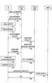
- Fig. 1 shows a flow of a handover procedure in conformity with LTE in a radio communication not involving the carrier aggregation as an example of a typical handover procedure.
- a user equipment (UE), a source base station (source eNB), a target base station (target eNB), and a mobility management entity (MME) are involved in the handover procedure.
- UE user equipment
- source eNB source base station
- target eNB target base station
- MME mobility management entity
- the user equipment first reports the channel quality of a communication channel between the user equipment and the source base station to the source base station (step S2).
- the channel quality may be reported on a regular basis or when the channel quality falls below a predetermined reference value.
- the user equipment can measure the channel quality of the communication channel with the source base station by receiving a reference signal contained in a downlink channel from the source base station.
- the source base station determines the needs of measurement based on the quality report received from the user equipment and, if measurement is necessary, allocates measurement gaps to the user equipment (step S4).
- the user equipment searches for a downlink channel from a peripheral base station (i.e. performs cell search) during the periods of the allocated measurement gaps (step S12).
- a peripheral base station i.e. performs cell search
- the user equipment can recognize a peripheral base station to search according to a list that is provided in advance from the source base station.
- the user equipment When the user equipment acquires synchronization with a downlink channel, the user equipment performs measurement by using a reference signal contained in the downlink channel (step S14). During this period, the source base station restricts an allocation of data communication related to the user equipment so as to avoid occurrence of data transmission by the user equipment.
- the user equipment Upon completion of the measurement, the user equipment transmits a measurement report containing measurements to the source base station (step S22).
- the measurements contained in the measurement report may be the average value or the central value of measured values over a plurality of times of measurement or the like. Further, the measurements may contain data about a plurality of frequency bands.
- the source base station determines whether or not to execute a handover based on the contents of the measurement report. For example, when the channel quality of another base station in the periphery is higher than the channel quality of the source base station by a predetermined threshold or greater, it can be determined that a handover is necessary. In this case, the source base station determines to carry out a handover procedure with the relevant another base station as a target base station, and transmits a handover request message to the target base station (step S24).
- the target base station determines whether it is possible to accept the user equipment according to the availability of a communication service offered by itself or the like. When it is possible to accept the user equipment, the target base station transmits a handover request confirm message to the source base station (step S26).
- the source base station transmits a handover command to the user equipment (step S28). Then, the user equipment acquires synchronization with the downlink channel of the target base station (step S32). After that, the user equipment makes a random access to the target base station by using a random access channel in a given time slot (step S34). During this period, the source base station forwards data addressed to the user equipment to the target base station (step S36). Then, after success in the random access, the user equipment transmits a handover complete message to the target base station (step S42).
- the target base station requests the MME to perform route update for the user equipment (step S44).
- the user equipment Upon updating the route of user data by the MME, the user equipment becomes able to communicate with another device through a new base station (i.e. the target base station). Then, the target base station transmits acknowledgement to the user equipment (step S46). A series of handover procedure thereby ends.
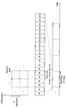
- Fig. 2 shows a structure of a communication resource in LTE as an example of a structure of a communication resource to which the present invention is applicable.
- the communication resource in LTE is segmented in the time direction into radio frames each having a length of 10 msec.
- One radio frame includes ten sub-frames, and one sub-frame is made up of two 0.5 msec slots.
- the sub-frame is one unit of an allocation of a communication resource to each user equipment in the time direction.
- Such one unit is called a resource block.
- One resource block includes twelve sub-carriers in the frequency direction. Specifically, one resource block has a size of 1 msec with 12 sub-carriers in the time-frequency domain.
- Throughput of data communication increases as a larger number of resource blocks are allocated for data communication on condition of the same bandwidth and time length.
- a part of radio frame with a given frequency band is reserved as a random access channel.
- the random access channel can be used for an access to a base station by a user equipment that has changed from an idle mode to an active mode or an initial access to a target base station in a handover procedure, for example.
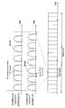
- Fig. 3 is an explanatory view to describe a cyclic prefix length (which is referred to hereinafter as a CP length) that can be adopted generally in the structure of a communication resource which is described above with reference to Fig. 2.
- a CP length cyclic prefix length
- a cyclic prefix length is a guard interval which is inserted between data symbols in order to avoid the occurrence of inter-symbol interference due to frequency selective fading caused by multipath delay spread over a communication channel.
- Fig. 3 shows two types of cyclic prefixes, an extended CP and a normal CP, by way of illustration.
- the extended CP six symbols are included in the 0.5ms slot which is described earlier with reference to Fig. 2. Further, the extended cyclic prefix having a length of 16.7microsec is inserted between the symbols.
- the normal cyclic prefix having a length of 4.7microsec is inserted between the symbols.
- the cyclic prefix typically contains a copy of the last portion of the data symbol.
- the extended CP or the normal CP is to be used is generally determined in each base station. Then, the type of cyclic prefix to be used is notified from a base station to a user equipment through a broadcast channel.
- the extended CP is used in the place where the multipath delay spread is particularly large.
- throughput decreases when using the extended CP compared to when using the normal CP.
- the extended CP and the normal CP are used in the base stations which are adjacent to each other, depending on the effect of the multipath delay spread.
- the user equipment can switch the setting of the CP length of the radio communication unit at the point of synchronization or a random access to the target base station.
- the situation occurs where a handover is completed for only a part of a plurality of component carriers. If, in view of such a situation, a circuit for simultaneously handling different CP lengths is applied in the radio communication unit, disadvantages occur such as complication of the circuit, an increase in manufacturing cost and an increase in processing load. Therefore, it is effective to employ the technique that can avoid simultaneous handling of different CP lengths during a handover procedure as in two embodiments of the present invention which are described in detail below.
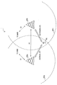
- Fig. 4 is a schematic view showing an outline of a radio communication system 1 according to an embodiment of the present invention.
- the radio communication system 1 includes a user equipment 100, a base station 200a and a base station 200b. It is assumed that the base station 200a is a serving base station for the user equipment 100.
- the user equipment 100 is located inside a cell 202a where a radio communication service is provided by the base station 200a.
- the user equipment 100 can perform a data communication with another user equipment (not shown) via the base station 200a over a communication channel formed by aggregating a plurality of component carriers (i.e. by carrier aggregation).
- a handover is required for the user equipment 100.
- the user equipment 100 is located inside a cell 202b where a radio communication service is provided by the base station 200b. Therefore, the base station 200b can be a candidate for a target base station for a handover of the user equipment 100.
- the base station 200a uses the CP length of the normal CP and the base station 200b uses the CP length of the extended CP, which are described earlier with reference to Fig. 3. Therefore, in order for the user equipment 100 to carry out a handover from the base station 200a to the base station 200b, it is necessary to change the setting of the CP length in the equipment at some point in time during a handover procedure.
- the base station 200a can communicate with the base station 200b through a backhaul link (e.g. X2 interface).
- a backhaul link e.g. X2 interface
- the base station 200a and the base station 200b can communicate with the MME, which is an upper node, through S1 interface, for example.
- base station 200a and the base station 200b are collectively referred to as a base station 200 by omitting the alphabetical letter at the end of the reference symbol. The same applies to the other elements.
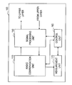
- Fig. 5 is a block diagram showing an example of a configuration of the user equipment 100 according to the embodiment.
- the user equipment 100 includes a radio communication unit 110, a signal processing unit 150, a buffer 152, a control unit 160, and a measurement unit 170.
- the radio communication unit 110 performs a radio communication with the base station 200 over a communication channel formed by aggregating a plurality of component carriers with use of the carrier aggregation technology.
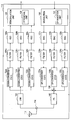
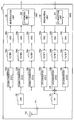
- Fig. 6 is a block diagram showing an example of a more detailed configuration of the radio communication unit 110.
- the radio communication unit 110 includes an antenna 112, a switch 114, a low noise amplifier (LNA) 120, a plurality of down-converters 122a to 122c, a plurality of filters 124a to 124c, a plurality of analogue-to-digital converters (ADCs) 126a to 126c, a demodulation unit 128, a modulation unit 130, a plurality of digital-to-analogue converters (DACs) 132a to 132c, a plurality of filters 134a to 134c, a plurality of up-converters 136a to 136c, a combiner 138, and a power amplifier (PA) 140.
- the demodulation unit 128 includes a CPU removal unit 129.
- the modulation unit 130 includes a CPU insertion unit 131.
- the antenna 112 receives a radio signal transmitted from the base station 200 and outputs the received signal to the LNA 120 through the switch 114.
- the LNA 120 amplifies the received signal.
- the down-converter 122a and the filter 124a separate a baseband signal of the first component carrier (CC1) from the received signal amplified by the LNA 120. Then, the separated baseband signal is converted to a digital signal by the ADC 126a and output to the demodulation unit 128.
- the down-converter 122b and the filter 124b separate a baseband signal of the second component carrier (CC2) from the received signal amplified by the LNA 120.
- the separated baseband signal is converted to a digital signal by the ADC 126b and output to the demodulation unit 128.
- the down-converter 122c and the filter 124c separate a baseband signal of the third component carrier (CC3) from the received signal amplified by the LNA 120.
- the separated baseband signal is converted to a digital signal by the ADC 126c and output to the demodulation unit 128.
- the CPU removal unit 129 removes a cyclic prefix from the baseband signals of the respective component carriers.
- the demodulation unit 128 then generates a data signal by demodulating the baseband signals and outputs the data signal to the signal processing unit 150.
- the modulation unit 130 modulates the data signal and generates baseband signals of the respective component carriers. Further, in the modulation unit 130, the CP insertion unit 131 inserts a cyclic prefix to the baseband signals. Among those baseband signals, the baseband signal of the first component carrier (CC1) is converted to an analog signal by the DAC 132a. Then, a frequency component corresponding to the first component carrier in a transmission signal is generated from the analog signal by the filter 134a and the up-converter 136a. Likewise, the baseband signal of the second component carrier (CC2) is converted to an analog signal by the DAC 132b.
- a frequency component corresponding to the second component carrier in the transmission signal is generated from the analog signal by the filter 134b and the up-converter 136b. Further, the baseband signal of the third component carrier (CC3) is converted to an analog signal by the DAC 132c. Then, a frequency component corresponding to the third component carrier in the transmission signal is generated from the analog signal by the filter 134c and the up-converter 136c. After that, the generated frequency components corresponding to the three component carriers are combined by the combiner 138, and the transmission signal is formed.
- the PA 140 amplifiers the transmission signal and outputs the transmission signal to the antenna 112 through the switch 114. Then, the antenna 112 transmits the transmission signal as a radio signal to the base station 200.
- the radio communication unit 110 handles three component carriers is described in Fig. 6, the number of component carriers handled by the radio communication unit 110 may be two, or four or more.
- the radio communication unit 110 may process the signals of the respective component carriers in the digital region.
- a digital signal converted by one ADC is separated into the signals of the respective component carriers by a digital filter.
- the signal is converted into an analog signal by one DAC.
- the load of the ADC and the DAC is generally smaller when processing the signals of the respective component carriers in the analog region.
- a sampling frequency for AD/DA conversion is higher, and the load of the ADC and the DAC can thereby increase.
- the signal processing unit 150 performs signal processing such as deinterleaving, decoding or error correction on the demodulated data signal that is input from the radio communication unit 110. Then, the signal processing unit 150 outputs the processed data signal to an upper layer. Further, the signal processing unit 150 performs signal processing such as encoding or interleaving on the data signal that is input from the upper layer. Then, the signal processing unit 150 outputs the processed data signal to the radio communication unit 110.
- the control unit 160 controls the overall functions of the user equipment 100 by using a processing device such as a central processing unit (CPU) or a digital signal processor (DSP). For example, the control unit 160 controls the timing of data communication by the radio communication unit 110 according to scheduling information that is received from the base station 200 by the radio communication unit 110. Further, the control unit 160 controls the measurement unit 170 to measure the channel quality by using a reference signal from the base station 200, which is a serving base station, and transmits the channel quality report to the base station 200 through the radio communication unit 110. Further, the control unit 160 controls the measurement unit 170 to execute measurement during the periods of measurement gaps which are allocated by the base station 200.
- a processing device such as a central processing unit (CPU) or a digital signal processor (DSP).
- the control unit 160 controls the timing of data communication by the radio communication unit 110 according to scheduling information that is received from the base station 200 by the radio communication unit 110.
- the control unit 160 controls the measurement unit 170 to measure the channel quality by using a reference signal from the base
- the control unit 160 acquires the CP length being used by the target base station by receiving system information from the relevant target base station.
- the system information is delivered through a broadcast channel which is placed in a prescribed position in the radio frame, for example.
- the control unit 160 controls the radio communication unit 110 to initiate a random access to the target base station after all of handover commands for all of the plurality of component carriers are received from the source base station by the radio communication unit 110.
- the control unit 160 changes the setting of the CP length in the radio communication unit 110 to the CP length being used by the target base station.
- control unit 160 may control the radio communication unit 110 to initiate a random access to the target base after receiving a handover command for any of the component carriers, without waiting for handover commands for the other component carriers. In this case, the control unit 160 does not need to change the setting of the CP length in the radio communication unit 110.
- the measurement unit 170 measures the channel quality for each of the component carriers by using a reference signal from the base station 200 according to control from the control unit 160, for example. Further, the measurement unit 170 executes measurement for a handover with respect to each of the component carriers by using the measurement gaps which are allocated by the base station 200. A result of the measurement executed by the measurement unit 170 is converted to a predetermined format for a measurement report by the control unit 160 and transmitted to the base station 200 through the radio communication unit 110. After that, the base station 200 determines, based on the measurement report, whether a handover should be executed or not for the user equipment 100.
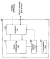
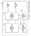
- Fig. 7 is a block diagram showing an example of a configuration of the base station 200 according to the embodiment.
- the base station 200 includes a radio communication unit 210, an interface unit 250, a component carrier (CC) management unit 260, and a control unit 280.
- CC component carrier
- Radio communication unit A specific configuration of the radio communication unit 210 may be similar to the configuration of the radio communication unit 110 of the user equipment 100 which is described above with reference to Fig. 6, although the number of component carriers to be supported, the requirements of processing performance or the like are different.
- the radio communication unit 210 performs a radio communication with the user equipment over a communication channel which is formed by aggregating a plurality of component carriers with use of the carrier aggregation technology.
- the interface unit 250 mediates a communication between the radio communication unit 210 or the control unit 280 and an upper node through the S1 interface illustrated in Fig. 4, for example. Further, the interface unit 250 mediates a communication between the radio communication unit 210 or the control unit 280 and another base station through the X2 interface illustrated in Fig. 4, for example.
- the CC management unit 260 holds data that indicates which component carrier each user equipment is using for communication with respect to each of the user equipments belonging to the cell of the base station 200. Such data can be updated by the control unit 280 when an additional user equipment joins the cell of the base station 200 or when the existing user equipment changes its component carriers. Thus, the control unit 280 can recognize which component carrier the user equipment 100 is using by referring to the data held by the CC management unit 260.
- the control unit 280 controls the overall functions of the base station 200 by using a processing device such as a CPU or a DSP. For example, the control unit 280 allocates communication resources for data communication to the user equipment 100 and other user equipments and then delivers scheduling information over a broadcast channel in a given sub-frame. Further, the control unit 280 delivers other system information over the broadcast channel, for example.
- the system information contains the set value of the CP length being used by the base station 200, for example. Further, the control unit 280 controls the base station 200 to operate in the same manner as the source base station or the target base station in the handover procedure which is descried with reference to Fig. 1.
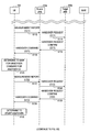
- a handover procedure according to the embodiment is described hereinafter with reference to Figs. 8A and 8B.
- a handover procedure is performed among the user equipment 100, the base station 200a serving as a source base station, and the base station 200b serving as a target base station.
- the user equipment 100 performs a radio communication by using two component carriers.
- explanation is omitted because there is no significant difference.
- the user equipment 100 first transmits a measurement report for the component carrier CC1, for example, to the base station 200a (step S112).
- the base station 200a determines the necessity of a handover based on the measurement report. For example, when a channel quality between the user equipment 100 and the base station 200b is better than a channel quality between the user equipment 100 and the base station 200a by a predetermined threshold or greater, it can be determined that a handover is necessary.
- the base station 200a transmits a handover request message for the component carrier CC1 to the base station 200b (step S114).
- the base station 200b determines whether it is possible to accept the user equipment 100 according to the availability of a communication service offered by itself or the like. When the base station 200b determines that it is possible to accept the user equipment 100, the base station 200b transmits a handover request confirm message to the base station 200a (step S116). Receiving the handover request confirm message, the base station 200a transmits a handover command for the component carrier CC1 to the user equipment 100 (step S118).
- the user equipment 100 acquires the CP length being used by the base station 200b by receiving system information from the base station 200b (for example, the system information may be received during execution of the measurement).
- the CP length being used by the base station 200b is the CP length of the extended CP.
- the CP length being used by the base station 200a is the CP length of the normal CP.
- the user equipment 100 which has received a handover command from the base station 200a determines to wait until a handover command for another component carrier (i.e. CC2) is received, without initiating a handover (S120).
- CC2 another component carrier
- the user equipment 100 transmits a measurement report for the component carrier CC2 to the base station 200a (step S122). Then, the base station 200a transmits a handover request message for the component carrier CC2 to the base station 200b (step S124). Receiving the handover request message, the base station 200b transmits a handover request confirm message to the base station 200a (step S126). Receiving the handover request confirm message, the base station 200a transmits a handover command for the component carrier CC2 to the user equipment 100 (step S128).
- step S128 ends, handover commands for all of the plurality of component carriers constituting the communication channel between the user equipment 100 and the base station 200a have been received by the user equipment 100. As a result, the user equipment 100 determines to initiate a handover (step S130).
- the user equipment 100 which has determined the initiation of a handover first acquires synchronization with the downlink channel of the component carrier CC1 of the base station 200b. Then, the user equipment 100 makes a random access to the base station 200b by using a random access channel in a given time slot of the component carrier CC1 (step S134). During this period, the base station 200a forwards data addressed to the user equipment 100 to the base station 200b (step S136). Then, after success in the random access for the component carrier CC1, the user equipment 100 transmits a handover complete message to the base station 200b (step S142).
- the base station 200b requests the MME to perform route update for the component carrier CC1 of the user equipment 100 (step S144).
- the user equipment 100 Upon updating the route of user data by the MME, the user equipment 100 becomes able to communicate with another device through a new base station (i.e. the base station 200b).
- the request for route update may be performed for each of the plurality of component carriers, or performed only once for the plurality of component carriers.
- the base station 200b transmits acknowledgement for the handover complete message to the user equipment 100 (step S146).
- the user equipment 100 acquires synchronization with the downlink channel of the component carrier CC2 of the base station 200b. Then, the user equipment 100 makes a random access to the base station 200b by using a random access channel in a given time slot of the component carrier CC2 (step S154). During this period, the base station 200a keeps forwarding data addressed to the user equipment 100 to the base station 200b (step S156). Then, after success in the random access for the component carrier CC2, the user equipment 100 transmits a handover complete message to the base station 200b (step S162). Receiving the handover complete message, the base station 200b requests the MME to perform route update for the component carrier CC2 of the user equipment 100 (step S164). Then, the base station 200b transmits acknowledgement for the handover complete message to the user equipment 100 (step S166).
- Fig. 9 is a sequence chart showing another example of a flow of a handover procedure according to the embodiment.
- the user equipment 100 first transmits a measurement report for the component carrier CC1 to the base station 200a (step S212). Further, the user equipment 100 first transmits a measurement report for the component carrier CC2 to the base station 200a (step S213). Note that those measurement reports may be integrated.
- the base station 200a determines the necessity of a handover based on the measurement report.
- the base station 200a first transmits a handover request message for the component carrier CC1 to the base station 200b (step S214).
- the base station 200a then transmits a handover request message for the component carrier CC2 to the base station 200b (step S215).
- the base station 200b determines whether it is possible to accept the user equipment 100 according to the availability of a communication service offered by itself or the like. When the base station 200b determines that it is possible to accept the user equipment 100, the base station 200b first transmits a handover request confirm message for the component carrier CC1 to the base station 200a (step S216). The base station 200b then transmits a handover request confirm message for the component carrier CC2 to the base station 200a (step S217).
- the base station 200a transmits a handover command for the component carrier CC1 to the user equipment 100 (step S218). Further, the base station 200a transmits a handover command for the component carrier CC2 to the user equipment 100 (step S219).
- the user equipment 100 waits until the handover command for the component carrier CC2 is received. Then, when the user equipment 100 receives the handover command for the component carrier CC2, it determines to initiate a handover (step S220).
- the user equipment 100 first acquires synchronization with the downlink channel of the component carrier CC1 of the base station 200b. Further, the user equipment 100 makes a random access to the base station 200b by using a random access channel in a given time slot of the component carrier CC1 (step S222). Then, the user equipment 100 acquires synchronization with the downlink channel of the component carrier CC2 of the base station 200b. Further, the user equipment 100 makes a random access to the base station 200b by using a random access channel in a given time slot of the component carrier CC2 (step S223). During this period, the base station 200a forwards data addressed to the user equipment 100 to the base station 200b (steps S224, S225).
- the user equipment 100 transmits a handover complete message for the component carrier CC1 to the base station 200b (step S232). Further, upon success in the random access for the component carrier CC2, the user equipment 100 transmits a handover complete message for the component carrier CC2 to the base station 200b (step S233). Receiving the handover complete messages, the base station 200b requests the MME to perform route update for the component carriers CC1 and CC2 of the user equipment 100 (steps S234, S235). Then, the base station 200b transmits acknowledgements for the respective handover complete messages to the user equipment 100 (steps S236, S237).
- the control unit 160 of the user equipment 100 initiates a random access to the target base station by the radio communication unit 110 after receiving handover commands for all of the plurality of component carriers constituting the communication channel.
- the control unit 160 of the user equipment 100 initiates a random access to the target base station by the radio communication unit 110 after receiving handover commands for all of the plurality of component carriers constituting the communication channel.
- a situation does not occur where the user equipment performs a communication with the source base station in a certain component carrier and also performs a communication with the target base station in another component carrier at the same time. It is thereby possible to avoid the user equipment 100 from simultaneously handing different CP lengths during a handover procedure.
- the user equipment 100 may initiate a random access soon after receiving a handover command for any of the component carriers, without waiting for a handover command for the other component carrier. It is thereby possible to complete a handover promptly for the component carrier for which a handover request is confirmed when it is not necessary to switch the CP length.
- the user equipment 100 may acquire the CP length being used by the target base station by using the system information which is broadcasted from the relevant target base station.
- the user equipment 100 may receive the system information which is broadcasted from the target base station at the time of measurement, for example. This configuration eliminates the need for exchanging an additional message for determination about waiting for a random access depending on the CP length, and it is thereby possible to reduce the impact on the existing system.
- communication resources are scheduled in such a way that the user equipment can perform a radio communication with the source base station and the target base station by switching the CP length in time division during a handover procedure.
- Fig. 10 is an explanatory view to describe an outline of switching of a cyclic prefix length in time division.
- a series of handover procedure can be divided into four stages.
- the first stage is before a handover.
- all component carriers are connected to the source base station.
- the second stage is after a handover of the component carrier CC1.
- the component carrier CC1 is connected to the target base station, and the component carriers CC2 and CC3 are connected to the source base station.
- the third stage is after a handover of the component carriers CC1 and CC2.
- the component carriers CC1 and CC2 are connected to the target base station, and the component carrier CC3 is connected to the source base station.
- the fourth stage is after a handover of all the component carriers.
- all component carriers are connected to the target base station.
- the user equipment can use the same CP length (e.g. the normal CP) at any point of time. Thus, the source base station can allocate communication resources for each component carrier without depending on the CP length.
- the user equipment can use the same CP length (e.g. the extended CP) at any point of time. Thus, the target base station can allocate communication resources for each component carrier without depending on the CP length.
- a part of a plurality of component carriers is connected to the target base station, and the rest is connected to the source base station.
- a communication resource is allocated only for any one component carrier with respect to each sub-frame by the source base station and the target base station, for example.
- a communication resource of the sub-frame SF1 is allocated for the component carrier CC1
- a communication resource of the sub-frame SF2 is allocated for the component carrier CC2
- a communication resource of the sub-frame SF3 is allocated for the component carrier CC3.
- a communication resource of the sub-frame SF4 is allocated for the component carrier CC1
- a communication resource of the sub-frame SF5 is allocated for the component carrier CC2
- a communication resource of the sub-frame SF6 is allocated for the component carrier CC3.
- Such an allocation of communication resources can be achieved by exchanging scheduling information between the source base station and the target base station through a backhaul link, for example.
- a communication resource is allocated only for any one component carrier with respect to each sub-frame.
- the user equipment can communicate with the respective base stations in time division by changing the setting of the CP length with respect to each sub-frame. Changing the CP length to use with respect to each subframe during a handover procedure results in avoiding simultaneous handling of different cyclic prefix lengths in one user equipment.
- the ratio (ratio in a given time window) of the amount of communication resource allocated for a part of component carrier for which a handover is completed and the amount of communication resource allocated for the rest of the component carriers is substantially the same as the radio of the number of component carriers between the former and the latter.
- the ratio of the amount of communication resources at the second stage is 1:2 (after:before handover).
- the ratio of the amount of communication resources at the third stage is 2:1 (after:before handover).
- Fig. 11 is a block diagram showing an example of a configuration of the user equipment 300 according to the embodiment.
- the user equipment 300 includes a radio communication unit 310, a signal processing unit 150, a control unit 360, and a measurement unit 170.
- the radio communication unit 310 performs a radio communication with the base station 400 over a communication channel formed by aggregating a plurality of component carriers with use of the carrier aggregation technology.
- Fig. 12 is a block diagram showing an example of a detailed configuration of the radio communication unit 310.
- the demodulation unit 128 of the radio communication unit 310 includes a CPU removal unit 329.
- the modulation unit 130 includes a CPU insertion unit 331.
- the CPU removal unit 329 removes a cyclic prefix from the baseband signal of each component carrier which is input to the demodulation unit 128.
- the CP length of the cyclic prefix which is removed by the CPU removal unit 329 can be switched with respect to each sub-frame according to a CP length control signal SIG1 that is input from the control unit 360.
- the CPU insertion unit 331 inserts a cyclic prefix into the baseband signal which is generated by the modulation unit 130.
- the CP length of the cyclic prefix which is inserted by the CPU insertion unit 331 can be switched with respect to each sub-frame according to a CP length control signal SIG2 that is input from the control unit 360.
- the operation of the radio communication unit 310 other than the switching of the setting of the CP length in the CPU removal unit 329 and the CPU insertion unit 331 may be the same as the operation of the radio communication unit 110 according to the first embodiment described above with reference to Fig. 5.
- the control unit 360 controls the overall functions of the user equipment 300, like the control unit 160 according to the first embodiment. For example, the control unit 360 controls the timing of data communication by the radio communication unit 310 according to scheduling information that is received from the base station 400 by the radio communication unit 310. Further, in this embodiment, the control unit 360 switches the setting of the CP length of the CPU removal unit 329 and the CPU insertion unit 331 of the radio communication unit 310 with respect to each sub-frame according to the allocation of communication resources by outputting the CP length control signals SIG1 and SIG2 to the radio communication unit 310 at the state during a handover procedure (e.g. at the second and third stages described with reference to Fig. 10).
- a handover procedure e.g. at the second and third stages described with reference to Fig. 10
- the synchronization to a downlink channel from the base station is performed by using both of a primary synchronization signal that is transmitted in the first sub-frame and a secondary synchronization signal that is transmitted in the sixth sub-frame in one radio frame. Therefore, it is preferred in the synchronization processing to switch the base station to be synchronized with respect to each radio frame, not each sub-frame.
- a synchronous circuit for the normal CP and a synchronous circuit for the extended CP may be placed in parallel in the radio communication unit 310. In this case, it is not necessary to switch the base station to be synchronized with respect to each radio frame. Because the synchronous circuit is implemented only in the physical layer, an impact on the system is small even when a plurality of synchronous circuits are placed in parallel.
- delivery of system information from the base station is also performed in a particular sub-frame in one radio frame. Therefore, for the reception of system information in the user equipment 100, like the synchronization processing described above, it is preferred to switch the base station to be synchronized with respect to each radio frame, not each sub-frame. In this case, because the base station 400 delivers the same system information over a plurality of successive radio frames, the user equipment 300 can acquire the system information of the source base station and the target base station without a loss.
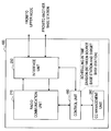
- Fig. 13 is a block diagram showing an example of a configuration of the base station 400 according to the embodiment.
- the base station 400 includes a radio communication unit 210, an interface unit 250, a CC management unit 260, and a control unit 480.
- the control unit 480 controls the overall functions of the base station 400. For example, the control unit 480 allocates communication resources for data communication to the user equipment 300 and other user equipments and then delivers scheduling information over a broadcast channel in a given sub-frame. Further, the control unit 480 delivers other system information over the broadcast channel, for example.
- the system information contains the set value of the CP length being used by the base station 400, for example.
- the control unit 480 of the source base station allocates a communication resource in a sub-frame, which is different from a sub-frame in which a communication resource is allocated by the target base station for a part of component carriers for which a handover is completed, for the rest of the component carriers.
- the control unit 480 acquires scheduling information for a part of component carriers for which a handover is completed from the target base station through a backhaul link, for example. Then, the control unit 480 allocates a communication resource in a sub-frame in which a communication resource is not allocated in the scheduling information for the rest of the component carriers.
- control unit 480 adjusts scheduling so that the ratio of the amount of communication resource allocated for a part of component carriers for which a handover is completed and the amount of communication resource allocated for the rest of the component carriers is substantially the same as the radio of the number of component carriers between the former and the latter.
- control unit 480 of the source base station acquires the ratio between the number of component carriers after handover completion and the number of component carriers before handover completion (which is referred to hereinafter as the ratio of the number of CCs) based on information exchange with the target base station.
- the control unit 480 allocates communication resources to the user equipment 100 in such a way that the ratio of the amount of communication resources is substantially the same as the ratio of the number of CCs.
- the control unit 480 may designate the amount of communication resources which the target base station should allocate to the user equipment 100 to the target base station through a backhaul link.
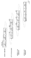
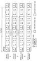
- Fig. 14 is an explanatory view to describe an example of a flow of a handover procedure according to the embodiment.
- Fig. 14 shows an allocation of communication resources at the four stages related to the handover procedure which is performed in the same manner as shown in Fig. 10. Note that, in Fig. 14, like Fig. 10, the user equipment sequentially executes a handover from the source base station to the target base station for three component carriers CC1 to CC3.
- any sub-frame can be allocated for the component carriers before completion of a handover (using the normal CP). Note that it is not practically necessary to allocate communication resources to all of those sub-frames. Further, the synchronization signal is used for the synchronization with the source base station.
- the ratio of the number of CCs is 1:2 (after:before handover). Therefore, among the six successive sub-frames (excluding the sub-frame for the synchronization signal), for example, two sub-frames can be allocated for the component carrier after completion of a handover (using the extended CP), and four sub-frames can be allocated for the component carrier before completion of a handover. For example, when a handover is completed for the component carrier CC1, a first sub-frame (#1) and a second sub-frame (#2) can be allocated for the component carrier CC1. Further, after the synchronization signal in one radio frame is used for the synchronization with the source base station, the synchronization signal in the next radio frame can be used for the synchronization with the target base station.
- the ratio of the number of CCs is 2:1 (after:before handover). Therefore, among the six successive sub-frames (excluding the sub-frame for the synchronization signal), for example, four sub-frames can be allocated for the component carrier after completion of a handover (using the extended CP), and two sub-frames can be allocated for the component carrier before completion of a handover. For example, when a handover is completed for the component carrier CC2 subsequent to the component carrier CC1, a third sub-frame (#3) and a fourth sub-frame (#4) can be allocated for the component carrier CC2. Further, after the synchronization signal in one radio frame is used for the synchronization with the source base station, the synchronization signal in the next radio frame can be used for the synchronization with the target base station.
- any sub-frame can be allocated for the component carriers after completion of a handover. Further, the synchronization signal is used for the synchronization with the target base station.
- the user equipment 300 can sequentially perform radio communications with the source base station and the target base station during a handover procedure by switching the CP length in time division manner. It is thereby possible to avoid simultaneous handling of different cyclic prefix lengths during a handover procedure in a radio communication involving the carrier aggregation.
- scheduling is adjusted so that the ratio of the amount of communication resource allocated by the target base station for the component carrier with handovers completed and the amount of communication resource allocated by the source base station for the component carrier with handovers not yet completed is substantially the same as the radio of the number of component carriers with handovers completed and the number of component carriers with handovers not yet completed.
- the amount of traffic is thereby equally shared among the component carriers, and it is thus possible to carry out data transmission during a handover procedure.
- the user equipment 300 may perform the synchronization with the source base station by using the synchronization signal in a radio frame which is different from a radio frame in which the synchronization signal to be used for the synchronization with the target base station is contained. Further, the user equipment 300 can receive system information from the source base station in a radio frame which is different from a radio frame in which system information from the target base station is received. This configuration eliminates the need for using a plurality of synchronous circuits or a plurality of processing units for handling different CP lengths, and it is thereby possible to suppress the manufacturing cost of the device.
- RADIO COMMUNICATION SYSTEM 100 300 USER EQUIPMENT 110, 310 RADIO COMMUNICATION UNIT (USER EQUIPMENT) 160, 360 CONTROL UNIT (USER EQUIPMENT) 200, 400 BASE STATION 210 RADIO COMMUNICATION UNIT (BASE STATION) 280, 480 CONTROL UNIT (BASE STATION)
Abstract
Description
1. Description of Related Art
1-1. Handover Procedure
1-2. Structure of Communication Resource
1-3. Description of Issue
2. Outline of Radio Communication System
3. Description of First Embodiment
3-1. Exemplary Configuration of User Equipment
3-2. Exemplary Configuration of Base Station
3-3. Flow of Process
3-4. Summary of First Embodiment
4. Description of Second Embodiment
4-1. Exemplary Configuration of User Equipment
4-2. Exemplary Configuration of Base Station
4-3. Flow of Process
4-4. Summary of Second Embodiment
(1-1. Handover Procedure)
A technique related to the present invention is described hereinafter with reference to Figs. 1 to 3. Fig. 1 shows a flow of a handover procedure in conformity with LTE in a radio communication not involving the carrier aggregation as an example of a typical handover procedure. In this example, a user equipment (UE), a source base station (source eNB), a target base station (target eNB), and a mobility management entity (MME) are involved in the handover procedure.
Fig. 2 shows a structure of a communication resource in LTE as an example of a structure of a communication resource to which the present invention is applicable. Referring to Fig. 2, the communication resource in LTE is segmented in the time direction into radio frames each having a length of 10 msec. One radio frame includes ten sub-frames, and one sub-frame is made up of two 0.5 msec slots. In LTE, the sub-frame is one unit of an allocation of a communication resource to each user equipment in the time direction. Such one unit is called a resource block. One resource block includes twelve sub-carriers in the frequency direction. Specifically, one resource block has a size of 1 msec with 12 sub-carriers in the time-frequency domain. Throughput of data communication increases as a larger number of resource blocks are allocated for data communication on condition of the same bandwidth and time length. Further, in such a structure of a communication resource, a part of radio frame with a given frequency band is reserved as a random access channel. The random access channel can be used for an access to a base station by a user equipment that has changed from an idle mode to an active mode or an initial access to a target base station in a handover procedure, for example.
An issue related to a handover procedure in a radio communication involving the carrier aggregation is described hereinafter with reference to Fig. 3. Fig. 3 is an explanatory view to describe a cyclic prefix length (which is referred to hereinafter as a CP length) that can be adopted generally in the structure of a communication resource which is described above with reference to Fig. 2.
Fig. 4 is a schematic view showing an outline of a
A first embodiment of the present invention for avoiding simultaneous handling of different CP lengths during a handover procedure in a radio communication involving the carrier aggregation is described hereinafter with reference to Figs. 5 to 9.
Fig. 5 is a block diagram showing an example of a configuration of the
The
Referring back to Fig. 5, an example of a configuration of the
The
The
Fig. 7 is a block diagram showing an example of a configuration of the
A specific configuration of the
The
The
The
A handover procedure according to the embodiment is described hereinafter with reference to Figs. 8A and 8B. Note that, in the following scenario, it is assumed that a handover procedure is performed among the
The first embodiment of the present invention is described above with reference to Figs. 5 to 9. According to the embodiment, the
A second embodiment of the present invention for avoiding simultaneous handling of different CP lengths during a handover procedure in a radio communication involving the carrier aggregation is described hereinafter with reference to Figs. 10 to 14.
Fig. 11 is a block diagram showing an example of a configuration of the
The
The
Fig. 13 is a block diagram showing an example of a configuration of the
The
Fig. 14 is an explanatory view to describe an example of a flow of a handover procedure according to the embodiment. Fig. 14 shows an allocation of communication resources at the four stages related to the handover procedure which is performed in the same manner as shown in Fig. 10. Note that, in Fig. 14, like Fig. 10, the user equipment sequentially executes a handover from the source base station to the target base station for three component carriers CC1 to CC3.
The second embodiment of the present invention is described above with reference to Figs. 10 to 14. According to the embodiment, when a handover to the target base station is completed only for a part of a plurality of component carriers, a communication resource in a sub-frame which is different from a sub-frame within which a communication resource is allocated by the target base station for the part of the plurality of component carriers is allocated by the source base station for the rest of the plurality of component carriers. In this configuration, a situation does not occur where the
100, 300 USER EQUIPMENT
110, 310 RADIO COMMUNICATION UNIT (USER EQUIPMENT)
160, 360 CONTROL UNIT (USER EQUIPMENT)
200, 400 BASE STATION
210 RADIO COMMUNICATION UNIT (BASE STATION)
280, 480 CONTROL UNIT (BASE STATION)
Claims (20)
- A mobile station in a wireless communication network, the mobile station comprising:
a radio communication unit configured to communicate with a first base station via a plurality of component carriers; and
a control unit configured to control the radio communication unit to initiate a handover procedure to a second base station after receiving at least one handover command for the plurality of component carriers. - The mobile station of claim 1, wherein
the radio communication unit is configured to communicate with the first base station via one of the plurality of component carriers having a first cyclic prefix length, and communicate with the second base station via one of the plurality of component carriers having a second cyclic prefix length. - The mobile station of claim 1, wherein
the radio communication unit is configured to receive a plurality of handover commands, each corresponding to one of the plurality of component carriers, and
the control unit is configured to control the radio communication unit to initiate a handover procedure to the second base station for each of the plurality of component carriers after receiving the plurality of handover commands. - A mobile station in a wireless communication network, the mobile station comprising:
a radio communication unit configured to communicate with a first base station via a plurality of component carriers each having a first cyclic prefix length; and
a control unit configured to control the radio communication unit to initiate a handover procedure from the first base station to a second base station after receiving a handover command,
wherein, after a handover for one of the plurality of component carriers, the control unit is configured to control the radio communication unit to communicate with the second base station via a component carrier allocated to a time slot different from a time slot to which each of the plurality of component carriers are allocated, and having a second cyclic prefix length different from the first cyclic prefix length. - The mobile station of claim 4, wherein
the control unit is configured to control the radio communication unit to release a first one of the plurality of component carrier connections with the first base station and to connect to the second base station using the component carrier having the second cyclic prefix length. - The mobile station of claim 5, wherein
the control unit is configured to control the radio communication unit to initiate a handover procedure to the second base station for a second one of the plurality of component carriers after the handover procedure for the first one of the plurality of component carriers has been initiated. - A base station in a wireless communication network, the base station comprising:
a radio communication unit configured to communicate with a mobile station via a plurality of component carriers; and
a control unit configured to control the radio communication unit to initiate a handover procedure to a second base station for one of the plurality of component carriers after receiving a report from the mobile station corresponding to the one of the plurality of component carriers. - The base station of claim 7, wherein
the control unit is configured to initiate the handover procedure by controlling the radio communication unit to transmit a handover request command to the second base station and transmit a handover command to the mobile station. - A base station in a wireless communication network, the base station comprising:
a radio communication unit configured to communicate with a mobile station via a plurality of component carriers each having a first cyclic prefix length; and
a control unit configured to control the radio communication unit to initiate a handover procedure to a second base station for one of the plurality of component carriers,
wherein, after a handover for one of the plurality of component carriers, the mobile station communicates with the second base station via a component carrier allocated to a time slot different from a time slot to which each of the plurality of component carriers is allocated, and having a second cyclic prefix length different from the first cyclic prefix length. - The base station of claim 9, wherein
the control unit is configured to initiate the handover procedure by controlling the radio communication unit to transmit a handover request command to the second base station and transmit a handover command to the mobile station. - A handover method performed by a mobile station in a wireless communication network, the method comprising:
communicating, by a radio communication unit of the mobile station, with a first base station via a plurality of component carriers; and
initiating, by a control unit of the mobile station, a handover procedure to a second base station after receiving at least one handover command for the plurality of component carriers. - A handover method performed by a mobile station in a wireless communication network, the method comprising:
communicating, by a radio communication unit of the mobile station, with a first base station via a plurality of component carriers each having a first cyclic prefix length;
initiating, by a control unit of the mobile station, a handover procedure from the first base station to the second base station after receiving a handover command; and
controlling, by the control unit after a handover for one of the plurality of component carriers, the radio communication unit to communicate with the second base station via a component carrier allocated to a time slot different from a time slot to which each of the plurality of component carriers are allocated, and having a second cyclic prefix length different from the first cyclic prefix length. - A handover method performed by a base station in a wireless communication network, the method comprising:
communicating, by a radio communication unit of the base station, with a mobile station via a plurality of component carriers; and
initiating, by a control unit of the base station, a handover procedure to a second base station for one of the plurality of component carriers after receiving a report from the mobile station corresponding to the one of the plurality of component carriers. - A handover method performed by a base station in a wireless communication network, the method comprising:
communicating, by a radio communication unit of the base station, with a mobile station via a plurality of component carriers each having a first cyclic prefix length; and
initiating, by a control unit of the base station, a handover procedure to a second base station for one of the plurality of component carrier;
wherein, after a handover for one of the plurality of component carriers, the mobile station communicates with the second base station via a component carrier allocated to a time slot different from a time slot to which each of the plurality of component carriers is allocated, and having a second cyclic prefix length different from the first cyclic prefix length. - A non-transitory computer readable medium including computer-program instructions, which when executed by a mobile station in a wireless communication network, cause the mobile station to perform a handover method comprising:
communicating with a first base station via a plurality of component carriers; and
initiating a handover procedure to a second base station after receiving at least one handover command for the plurality of component carriers. - A non-transitory computer readable medium including computer-program instructions, which when executed by a mobile station in a wireless communication network, cause the mobile station to perform a handover method comprising:
communicating with a first base station via a plurality of component carriers each having a first cyclic prefix length;
initiating a handover procedure from the first base station to the second base station after receiving a handover command; and
communicating, after a handover for one of the plurality of component carriers, with the second base station via a component carrier allocated to a time slot different from a time slot to which each of the plurality of component carriers are allocated, and having a second cyclic prefix length different from the first cyclic prefix length. - A non-transitory computer readable medium including computer-program instructions, which when executed by a base station in a wireless communication network, cause the base station to perform a handover method comprising:
communicating with a mobile station via a plurality of component carriers; and
initiating a handover procedure to a second base station for one of the plurality of component carriers after receiving a report from the mobile station corresponding to the one of the plurality of component carriers. - A non-transitory computer readable medium including computer-program instructions, which when executed by a base station in a wireless communication network, cause the base station to perform a handover method comprising:
communicating with a mobile station via a plurality of component carriers each having a first cyclic prefix length; and
initiating a handover procedure to a second base station for one of the plurality of component carriers,
wherein, after a handover for one of the plurality of component carriers, the mobile station communicates with the second base station via a component carrier allocated to a time slot different from a time slot to which each of the plurality of component carriers is allocated, and having a second cyclic prefix length different from the first cyclic prefix length. - A wireless communication system comprising:
a mobile station including a radio communication unit configured to communicate with a first base station via a plurality of component carriers;
a first control unit at the first base station configured to initiate a handover procedure to a second base station for one of the plurality of component carriers after receiving a report from the mobile station corresponding to the one of the plurality of component carriers; and
a second control unit at the mobile station configured to initiate a handover procedure to the second base station after receiving at least one handover command for the plurality of component carriers from the first base station. - A wireless communication system comprising:
a first base station configured to communicate with a mobile station via a plurality of component carriers each having a first cyclic prefix length;
the mobile station configured to initiate a handover procedure from the first base station to a second base station for one of the plurality of component carriers after receiving a handover command from the first base station; and
the second base station configured to communicate with the mobile station via a component carrier allocated to a time slot different from a time slot to which each of the plurality of component carriers is allocated, and having a second cyclic prefix length different from the first cyclic prefix length.
Priority Applications (6)
| Application Number | Priority Date | Filing Date | Title |
|---|---|---|---|
| EP10837240.0A EP2514235B1 (en) | 2009-12-16 | 2010-12-06 | User equipment, method for performing handover, base station, and radio communication system |
| RU2012123983/07A RU2012123983A (en) | 2009-12-16 | 2010-12-06 | USER DEVICE, METHOD FOR CARRYING OUT SERVICE TRANSFER, BASE STATION AND RADIO COMMUNICATION SYSTEM |
| BR112012013892A BR112012013892A2 (en) | 2009-12-16 | 2010-12-06 | mobile station, base station, transfer method performed by a mobile station on a wireless communication network, non-transient computer readable medium, and wireless communication system |
| IN5076DEN2012 IN2012DN05076A (en) | 2009-12-16 | 2010-12-06 | |
| US13/514,141 US9491670B2 (en) | 2009-12-16 | 2010-12-06 | User equipment, method for performing handover, base station, and radio communication system |
| CN201080056921.XA CN102656920B (en) | 2009-12-16 | 2010-12-06 | Subscriber equipment, changing method, base station and radio communications system |
Applications Claiming Priority (2)
| Application Number | Priority Date | Filing Date | Title |
|---|---|---|---|
| JP2009-285372 | 2009-12-16 | ||
| JP2009285372A JP2011130088A (en) | 2009-12-16 | 2009-12-16 | User equipment, method for performing handover, base station, and radio communication system |
Publications (1)
| Publication Number | Publication Date |
|---|---|
| WO2011074203A1 true WO2011074203A1 (en) | 2011-06-23 |
Family
ID=44166978
Family Applications (1)
| Application Number | Title | Priority Date | Filing Date |
|---|---|---|---|
| PCT/JP2010/007091 WO2011074203A1 (en) | 2009-12-16 | 2010-12-06 | User equipment, method for performing handover, base station, and radio communication system |
Country Status (8)
| Country | Link |
|---|---|
| US (1) | US9491670B2 (en) |
| EP (1) | EP2514235B1 (en) |
| JP (1) | JP2011130088A (en) |
| CN (1) | CN102656920B (en) |
| BR (1) | BR112012013892A2 (en) |
| IN (1) | IN2012DN05076A (en) |
| RU (1) | RU2012123983A (en) |
| WO (1) | WO2011074203A1 (en) |
Cited By (1)
| Publication number | Priority date | Publication date | Assignee | Title |
|---|---|---|---|---|
| CN102843724A (en) * | 2012-07-30 | 2012-12-26 | 东南大学 | Energy conservation method in mobile communication system carrier aggregation scene |
Families Citing this family (12)
| Publication number | Priority date | Publication date | Assignee | Title |
|---|---|---|---|---|
| JP5445186B2 (en) | 2009-10-30 | 2014-03-19 | ソニー株式会社 | Base station, terminal device, communication control method, and radio communication system |
| KR20110111790A (en) * | 2010-04-05 | 2011-10-12 | 주식회사 팬택 | Method and apparatus for signaling component carrier information of handover in communication system using multiple component carrier |
| JP2013070159A (en) * | 2011-09-21 | 2013-04-18 | Sharp Corp | Base station, mobile station, communication control method, and program |
| GB2501953B (en) * | 2012-01-30 | 2014-11-05 | Broadcom Corp | Measurement reporting for mobility procedures |
| RU2631251C2 (en) * | 2013-05-31 | 2017-09-20 | Хуавэй Текнолоджиз Ко., Лтд. | Method of information exchange, base station and user device |
| EP3007497A4 (en) | 2013-09-27 | 2016-07-13 | Huawei Device Co Ltd | Method and user equipment for transmitting direct connection communication signals of user equipment |
| CN104541536B (en) | 2014-03-21 | 2017-04-26 | 华为终端有限公司 | Method, user equipment and base station for detecting device to device signals |
| US9774485B2 (en) | 2014-05-16 | 2017-09-26 | Qualcomm Incorporated | Multiplex modules for carrier aggregation receivers |
| US10390343B2 (en) | 2014-06-23 | 2019-08-20 | Qualcomm Incorporated | Carrier aggregation diversity antenna module with integrated LNA banks |
| CN107517098B (en) * | 2016-06-16 | 2019-10-01 | 上海朗帛通信技术有限公司 | A kind of method and apparatus of wireless transmission |
| CN108093445B (en) * | 2016-11-23 | 2020-11-03 | 韩国电子通信研究院 | Wireless unit selecting method and frame setting method |
| JP7237163B2 (en) * | 2019-01-11 | 2023-03-10 | エルジー エレクトロニクス インコーポレイティド | Method and apparatus for mobility in wireless communication system |
Citations (2)
| Publication number | Priority date | Publication date | Assignee | Title |
|---|---|---|---|---|
| JP2008118309A (en) * | 2006-11-01 | 2008-05-22 | Ntt Docomo Inc | Cell search method, mobile station and base station |
| JP2009232293A (en) | 2008-03-24 | 2009-10-08 | Ntt Docomo Inc | Handover control method, cell reselection method, and mobile station |
Family Cites Families (5)
| Publication number | Priority date | Publication date | Assignee | Title |
|---|---|---|---|---|
| US8582596B2 (en) * | 2004-06-04 | 2013-11-12 | Qualcomm Incorporated | Coding and modulation for broadcast and multicast services in a wireless communication system |
| US8509791B2 (en) * | 2007-03-17 | 2013-08-13 | Qualcomm Incorporated | Handover in wireless communications |
| US8676208B2 (en) * | 2008-06-11 | 2014-03-18 | Mediatek Inc. | Scanning and handover operation in multi-carrier wireless communications systems |
| CN102349329A (en) * | 2009-03-12 | 2012-02-08 | 交互数字专利控股公司 | Method and apparatus for performing component carrier-specific reconfiguration |
| JP2011097443A (en) * | 2009-10-30 | 2011-05-12 | Sony Corp | Method for handover, terminal, base station, and radio communication system |
-
2009
- 2009-12-16 JP JP2009285372A patent/JP2011130088A/en not_active Withdrawn
-
2010
- 2010-12-06 WO PCT/JP2010/007091 patent/WO2011074203A1/en active Application Filing
- 2010-12-06 RU RU2012123983/07A patent/RU2012123983A/en not_active Application Discontinuation
- 2010-12-06 IN IN5076DEN2012 patent/IN2012DN05076A/en unknown
- 2010-12-06 EP EP10837240.0A patent/EP2514235B1/en active Active
- 2010-12-06 CN CN201080056921.XA patent/CN102656920B/en active Active
- 2010-12-06 US US13/514,141 patent/US9491670B2/en active Active
- 2010-12-06 BR BR112012013892A patent/BR112012013892A2/en not_active IP Right Cessation
Patent Citations (2)
| Publication number | Priority date | Publication date | Assignee | Title |
|---|---|---|---|---|
| JP2008118309A (en) * | 2006-11-01 | 2008-05-22 | Ntt Docomo Inc | Cell search method, mobile station and base station |
| JP2009232293A (en) | 2008-03-24 | 2009-10-08 | Ntt Docomo Inc | Handover control method, cell reselection method, and mobile station |
Non-Patent Citations (5)
| Title |
|---|
| 3GPP TSG RAN WG2 MEETING, 24 August 2009 (2009-08-24) |
| 3GPP TSG RAN WG2 MEETING, 29 June 2009 (2009-06-29) |
| CATT: "Handover for Carrier Aggregation", 3GPP TSG RAN WG2 #66 R2-093722, 3 July 2009 (2009-07-03), XP008157247, Retrieved from the Internet <URL:http://ftp.3gpp.org/ftp/tsg_ran/WG2_RL2/TSGR266bis/docs/R2-093722.zip> [retrieved on 20110104] * |
| HUAWEI: "Intra LTE-A UE Handover Procedure inter-eNB for CA", 3GPP TSG RAN WG2 #67 R2-094731, 28 August 2009 (2009-08-28), XP008157210, Retrieved from the Internet <URL:http://ftp.3gpp.org/ftp/tsg_ran/WG2_RL2/TSGR267/docs/R2-094731.zip> [retrieved on 20110104] * |
| See also references of EP2514235A4 |
Cited By (1)
| Publication number | Priority date | Publication date | Assignee | Title |
|---|---|---|---|---|
| CN102843724A (en) * | 2012-07-30 | 2012-12-26 | 东南大学 | Energy conservation method in mobile communication system carrier aggregation scene |
Also Published As
| Publication number | Publication date |
|---|---|
| IN2012DN05076A (en) | 2015-10-09 |
| CN102656920A (en) | 2012-09-05 |
| RU2012123983A (en) | 2013-12-20 |
| EP2514235A4 (en) | 2016-03-16 |
| CN102656920B (en) | 2015-12-09 |
| US9491670B2 (en) | 2016-11-08 |
| EP2514235A1 (en) | 2012-10-24 |
| BR112012013892A2 (en) | 2016-05-03 |
| EP2514235B1 (en) | 2020-11-25 |
| JP2011130088A (en) | 2011-06-30 |
| US20120236830A1 (en) | 2012-09-20 |
Similar Documents
| Publication | Publication Date | Title |
|---|---|---|
| EP2514235B1 (en) | User equipment, method for performing handover, base station, and radio communication system | |
| US11570673B2 (en) | Method for performing handover, user equipment, and radio communication system | |
| US10932172B2 (en) | Method for controlling handover, user equipment, base station, and radio communication system | |
| US20190313299A1 (en) | Method for performing handover, user equipment, base station, and radio communication system | |
| US9578559B2 (en) | Method for performing handover, user equipment, base station, and radio communication system |
Legal Events
| Date | Code | Title | Description |
|---|---|---|---|
| WWE | Wipo information: entry into national phase |
Ref document number: 201080056921.X Country of ref document: CN |
|
| 121 | Ep: the epo has been informed by wipo that ep was designated in this application |
Ref document number: 10837240 Country of ref document: EP Kind code of ref document: A1 |
|
| 121 | Ep: the epo has been informed by wipo that ep was designated in this application |
Ref document number: 10837240 Country of ref document: EP Kind code of ref document: A1 |
|
| WWE | Wipo information: entry into national phase |
Ref document number: 2010837240 Country of ref document: EP |
|
| WWE | Wipo information: entry into national phase |
Ref document number: 13514141 Country of ref document: US |
|
| WWE | Wipo information: entry into national phase |
Ref document number: 2012123983 Country of ref document: RU Ref document number: 5076/DELNP/2012 Country of ref document: IN |
|
| NENP | Non-entry into the national phase |
Ref country code: DE |
|
| REG | Reference to national code |
Ref country code: BR Ref legal event code: B01A Ref document number: 112012013892 Country of ref document: BR |
|
| ENP | Entry into the national phase |
Ref document number: 112012013892 Country of ref document: BR Kind code of ref document: A2 Effective date: 20120608 |