WO2011073876A2 - Mimo feedback schemes for cross-polarized antennas - Google Patents

Mimo feedback schemes for cross-polarized antennas Download PDF

Info

Publication number
WO2011073876A2
WO2011073876A2 PCT/IB2010/055763 IB2010055763W WO2011073876A2 WO 2011073876 A2 WO2011073876 A2 WO 2011073876A2 IB 2010055763 W IB2010055763 W IB 2010055763W WO 2011073876 A2 WO2011073876 A2 WO 2011073876A2
Authority
WO
WIPO (PCT)
Prior art keywords
antennas
feedback
feedback information
matrix
time
Prior art date
Application number
PCT/IB2010/055763
Other languages
French (fr)
Other versions
WO2011073876A3 (en
Inventor
Adoram Erell
Krishna Srikanth Gomadam
Yan Zhang
Ezer Melzer
Original Assignee
Marvell World Trade Ltd
Priority date (The priority date is an assumption and is not a legal conclusion. Google has not performed a legal analysis and makes no representation as to the accuracy of the date listed.)
Filing date
Publication date
Application filed by Marvell World Trade Ltd filed Critical Marvell World Trade Ltd
Priority to CN201080057652.9A priority Critical patent/CN102783120B/en
Priority to EP10837147.7A priority patent/EP2514181B1/en
Priority to JP2012543960A priority patent/JP5637486B2/en
Publication of WO2011073876A2 publication Critical patent/WO2011073876A2/en
Publication of WO2011073876A3 publication Critical patent/WO2011073876A3/en

Links

Classifications

    • HELECTRICITY
    • H04ELECTRIC COMMUNICATION TECHNIQUE
    • H04BTRANSMISSION
    • H04B7/00Radio transmission systems, i.e. using radiation field
    • H04B7/02Diversity systems; Multi-antenna system, i.e. transmission or reception using multiple antennas
    • H04B7/10Polarisation diversity; Directional diversity
    • HELECTRICITY
    • H04ELECTRIC COMMUNICATION TECHNIQUE
    • H04BTRANSMISSION
    • H04B7/00Radio transmission systems, i.e. using radiation field
    • H04B7/02Diversity systems; Multi-antenna system, i.e. transmission or reception using multiple antennas
    • H04B7/04Diversity systems; Multi-antenna system, i.e. transmission or reception using multiple antennas using two or more spaced independent antennas
    • H04B7/06Diversity systems; Multi-antenna system, i.e. transmission or reception using multiple antennas using two or more spaced independent antennas at the transmitting station
    • H04B7/0613Diversity systems; Multi-antenna system, i.e. transmission or reception using multiple antennas using two or more spaced independent antennas at the transmitting station using simultaneous transmission
    • H04B7/0615Diversity systems; Multi-antenna system, i.e. transmission or reception using multiple antennas using two or more spaced independent antennas at the transmitting station using simultaneous transmission of weighted versions of same signal
    • H04B7/0619Diversity systems; Multi-antenna system, i.e. transmission or reception using multiple antennas using two or more spaced independent antennas at the transmitting station using simultaneous transmission of weighted versions of same signal using feedback from receiving side
    • H04B7/0621Feedback content
    • H04B7/063Parameters other than those covered in groups H04B7/0623 - H04B7/0634, e.g. channel matrix rank or transmit mode selection
    • HELECTRICITY
    • H04ELECTRIC COMMUNICATION TECHNIQUE
    • H04BTRANSMISSION
    • H04B7/00Radio transmission systems, i.e. using radiation field
    • H04B7/02Diversity systems; Multi-antenna system, i.e. transmission or reception using multiple antennas
    • H04B7/04Diversity systems; Multi-antenna system, i.e. transmission or reception using multiple antennas using two or more spaced independent antennas
    • H04B7/06Diversity systems; Multi-antenna system, i.e. transmission or reception using multiple antennas using two or more spaced independent antennas at the transmitting station
    • H04B7/0613Diversity systems; Multi-antenna system, i.e. transmission or reception using multiple antennas using two or more spaced independent antennas at the transmitting station using simultaneous transmission
    • H04B7/0615Diversity systems; Multi-antenna system, i.e. transmission or reception using multiple antennas using two or more spaced independent antennas at the transmitting station using simultaneous transmission of weighted versions of same signal
    • H04B7/0619Diversity systems; Multi-antenna system, i.e. transmission or reception using multiple antennas using two or more spaced independent antennas at the transmitting station using simultaneous transmission of weighted versions of same signal using feedback from receiving side
    • H04B7/0636Feedback format
    • H04B7/0641Differential feedback
    • HELECTRICITY
    • H04ELECTRIC COMMUNICATION TECHNIQUE
    • H04BTRANSMISSION
    • H04B7/00Radio transmission systems, i.e. using radiation field
    • H04B7/02Diversity systems; Multi-antenna system, i.e. transmission or reception using multiple antennas
    • H04B7/04Diversity systems; Multi-antenna system, i.e. transmission or reception using multiple antennas using two or more spaced independent antennas
    • H04B7/06Diversity systems; Multi-antenna system, i.e. transmission or reception using multiple antennas using two or more spaced independent antennas at the transmitting station
    • H04B7/0613Diversity systems; Multi-antenna system, i.e. transmission or reception using multiple antennas using two or more spaced independent antennas at the transmitting station using simultaneous transmission
    • H04B7/0615Diversity systems; Multi-antenna system, i.e. transmission or reception using multiple antennas using two or more spaced independent antennas at the transmitting station using simultaneous transmission of weighted versions of same signal
    • H04B7/0619Diversity systems; Multi-antenna system, i.e. transmission or reception using multiple antennas using two or more spaced independent antennas at the transmitting station using simultaneous transmission of weighted versions of same signal using feedback from receiving side
    • H04B7/0658Feedback reduction
    • H04B7/0663Feedback reduction using vector or matrix manipulations

Definitions

  • the present disclosure relates generally to communication systems, and particularly to methods and systems for providing channel feedback in Multiple-Input Multiple-Output (MIMO) communication systems.
  • MIMO Multiple-Input Multiple-Output
  • MIMO Multiple-Input Multiple- Output
  • E-UTRA Evolved Universal Terrestrial Radio Access
  • LTE Long Term Evolution
  • LTE-A LTE-Advanced
  • 3 GPP TSG RAN document Rl -094690 entitled “Use of UL Covariance for Downlink MIMO in FDD,” Jeju, Korea, November 9-13, 2009, which is incorporated herein by reference in its entirety, discusses the use of the uplink covariance matrix for downlink MIMO.
  • Some MIMO feedback schemes use precoding codebooks, i.e., predefined sets of precoding matrices.
  • Codebook-based feedback schemes are described, for example, in 3GPP Technical Specification 36.213, entitled "Technical Specification Group Radio Access
  • E-UTRA Evolved Universal Terrestrial Radio Access
  • Physical Layer Procedures Evolved Universal Terrestrial Radio Access (E-UTRA); Physical Layer Procedures
  • Some MIMO feedback schemes are defined for cross-polarized antenna arrays.
  • An example technique of this kind is described in 3GPP TSG RAN document Rl- 94844, entitled “Low Overhead Feedback of Spatial Covariance Matrix,” Jeju, Korea, November 9-13, 2009, which is incorporated herein by reference in its entirety.
  • Another example is described in 3GPP TSG RAN document Rl-91229, entitled “Discussion on Enhanced DL Beamforming," Seoul, Korea, March 23-27, 2009, which is incorporated herein by reference in its entirety.
  • An embodiment that is described herein provides a method, which includes receiving a Multiple-Input Multiple Output (MIMO) signal over multiple communication channels from an antenna array.
  • the antenna array includes a first set of antennas having a first polarization and a second set of the antennas having a second polarization that is orthogonal to the first polarization.
  • First feedback information is calculated relating to first interrelations between the antennas within either the first set or the second set.
  • Second feedback information is calculated relating at least to second interrelations between the first set and the second set of the antennas.
  • the first feedback information is transmitted at a first time/frequency granularity
  • the second feedback information is transmitted at a second time/frequency granularity that is finer than the first time/frequency granularity.
  • calculating the first and second feedback information includes calculating a feedback matrix, which is represented as a Kronecker product of a first matrix depending on the first interrelations and a second matrix depending on the second interrelations.
  • transmitting the first and second feedback information includes reporting the first matrix at the first time/frequency granularity and reporting the second matrix at the second time/frequency granularity.
  • calculating the feedback matrix includes estimating elements of a Spatial Correlation Function (SCF) matrix.
  • SCF Spatial Correlation Function
  • calculating the feedback matrix includes selecting a precoding matrix to be applied for subsequent transmission of the MIMO signal.
  • selecting the precoding matrix includes choosing the precoding matrix from a predefined set of precoding matrices, at least some of which are represented as Kronecker products of respective first matrices depending on the first interrelations and respective second matrices depending on the second interrelations.
  • transmitting the first and second feedback information at the first and second time/frequency granularities includes transmitting only the second feedback information and not the first feedback information.
  • calculating the second feedback includes computing the second feedback based on at least one additional feedback parameter, which depends on one or more of the antennas in the first set and one or more of the antennas in the second set.
  • calculating the first feedback information includes computing the first feedback information over first time intervals and over first frequency bands
  • calculating the second feedback information includes computing the second feedback information over second time intervals that are shorter than the first time intervals, and over second frequency bands that are narrower than the first frequency bands.
  • apparatus including a receiver, a processor and a transmitter.
  • the receiver is configured to receive a MIMO signal over multiple communication channels from an antenna array including a first set of antennas having a first polarization and a second set of the antennas having a second polarization that is orthogonal to the first polarization.
  • the processor is configured to calculate first feedback information relating to first interrelations between the antennas within either the first set or the second set, and to calculate second feedback information relating at least to second interrelations between the first set and the second set of the antennas.
  • the transmitter is configured to transmit the first feedback information at a first time/frequency granularity, and to transmit the second feedback information at a second time/frequency granularity that is finer than the first time/frequency granularity.
  • a mobile communication terminal includes the disclosed apparatus.
  • a chipset for processing signals in a mobile communication terminal includes the disclosed apparatus.
  • apparatus including an antenna array, a transmitter, a receiver and a processor.
  • the antenna array includes a first set of antennas having a first polarization and a second set of the antennas having a second polarization that is orthogonal to the first polarization.
  • the transmitter is configured to transmit a MIMO signal over multiple communication channels using the antenna array.
  • the receiver is configured to receive, at a first time/frequency granularity, first feedback information relating to first interrelations between the antennas within either the first set or the second set, and to receive, at a second time/frequency granularity that is finer than the first time/frequency granularity, second feedback information relating at least to second interrelations between the first set and the second set of the antennas.
  • the processor is configured to combine the first and second feedback information received respectively at the first and second time/frequency granularities, and to adapt transmission of the MIMO signal based on the combined first and second feedback.
  • Fig. 1 is a block diagram that schematically illustrates a Multiple-Input Multiple-Output (MIMO) communication system, in accordance with an embodiment that is described herein; and
  • MIMO Multiple-Input Multiple-Output
  • Fig. 2 is a flow chart that schematically illustrates a method for providing channel feedback in a MIMO communication system, in accordance with an embodiment that is described herein.
  • a MIMO transmitter e.g., a base station such as an LTE eNodeB transmits a MIMO signal using a cross-polarized antenna array, i.e., an array comprising two sets of antennas having mutually-orthogonal polarizations.
  • the antennas in the cross-polarized array are typically closely spaced, e.g., positioned at half wavelength (A/2) intervals.
  • a receiver e.g., a mobile communication terminal
  • receives the MIMO signal calculates feedback that is indicative of the communication channels corresponding to the different transmitter antennas, and sends the feedback to the transmitter.
  • the transmitter controls subsequent MIMO transmission based on the feedback from the receiver.
  • the level of correlation between the communication channels corresponding to the different transmitter antennas typically determines the rate at which the BS antenna interrelations (e.g., correlation or covariance) vary over time and frequency.
  • Highly-correlated communication channels typically correspond to slow variation of the interrelation over time/frequency, and vice versa.
  • the interrelations between transmitter antennas having the same polarization typically vary slowly over time and frequency, whereas the interrelations between antennas having orthogonal polarizations typically vary more rapidly.
  • the receiver uses the difference in correlation (and thus the difference in the rate of variation of the antenna interrelations) to reduce the volume of feedback information that is calculated and sent to the transmitter.
  • the receiver calculates two types of feedback information.
  • the first type of feedback information is based on interrelations between transmitter antennas having the same polarization.
  • the second type of feedback information is based at least on interrelations between antennas having orthogonal polarizations. Since, as explained above, the first type of feedback is typically slowly-varying, in an embodiment the receiver sends the first type of feedback information at a relatively coarse time/frequency granularity. The second type of feedback usually varies rapidly, and therefore in an embodiment the receiver sends the second type of feedback information at a relatively fine time/frequency granularity.
  • the receiver adds to the second feedback type one or more additional feedback parameters, which do not necessarily depend on antennas having orthogonal polarizations but are nevertheless updated at fine granularity.
  • the receiver By partitioning the feedback information in this manner, and updating part of the feedback information at coarse time/frequency granularity, the receiver reduces the bandwidth that is used for feedback transmission. Therefore, the disclosed techniques improve the spectral efficiency of MIMO communication systems with little or no degradation in feedback quality. Moreover, since part of the feedback information may be calculated at coarse time/frequency granularity, the computational load in the receiver is reduced.
  • PMI Precoding Matrix Index
  • SCF Spatial Correlation Function
  • Fig. 1 is a block diagram that schematically illustrates a Multiple-Input Multiple-Output (MIMO) communication system 20, in accordance with an embodiment that is described herein.
  • system 20 comprises an E-UTRA (LTE) system that operates in accordance with the TS 36.213 specification, cited above.
  • LTE E-UTRA
  • system 20 may operate in accordance with any other suitable communication standard or specification that uses MIMO signals, such as, for example, UMTS Terrestrial Radio Access (UTRA) systems (also sometimes referred to as Wideband Code Division Multiple Access - WCDMA) and WiMAX systems operating in accordance with IEEE 802.16 specifications.
  • UTRA UMTS Terrestrial Radio Access
  • WCDMA Wideband Code Division Multiple Access
  • WiMAX operating in accordance with IEEE 802.16 specifications.
  • System 20 comprises a Base Station (BS) 24 (e.g., an LTE eNodeB), which communicates with a mobile communication terminal 28 (also referred to as User Equipment - UE).
  • BS 24 comprises a BS processor 32, which manages the operation of the BS.
  • a BS transceiver (TRX) 36 generates downlink MIMO signals for transmission to UEs 28 and receives uplink signals from the UEs.
  • BS 24 transmits downlink signals and receives uplink signals using a cross- polarized antenna array 40.
  • Array 40 comprises a first set of antennas 44A...44D having a certain polarization, and a second set of antennas 48A...48D having a polarization that is orthogonal to the polarization of the first set.
  • one set of antennas is horizontally-polarized and the other set is vertically-polarized.
  • one set of antennas has a +45° polarization and the other set has a -45° polarization.
  • any other suitable orthogonal polarizations can be used.
  • array 40 comprises a total of eight antennas, four antennas in each set.
  • the antennas within each set are arranged in a Uniform Linear Array (ULA) configuration, in which the spacing between adjacent antennas is half wavelength (A/2).
  • ULA Uniform Linear Array
  • the antenna array may comprise any suitable number of antennas having any suitable positions.
  • UE 28 comprises one or more antennas 52, which receive the MIMO downlink signals that are transmitted from BS 24, and transmit uplink signals to the BS.
  • UE 28 comprises a downlink receiver (RX) 56 that receives and demodulates the downlink signals, an uplink transmitter (TX) 68 that generates and transmits the uplink signals, and a UE processor 60 that manages the UE operation and controls the various UE elements.
  • RX downlink receiver
  • TX uplink transmitter
  • UE processor 60 that manages the UE operation and controls the various UE elements.
  • UE processor 60 comprises a feedback calculation module 64, which calculates feedback information regarding the downlink communication channels between the BS antennas (44A...44D and 48A...48D) and UE antennas 52.
  • Module 64 calculates the feedback information based on the downlink signals received by downlink receiver 56, e.g., based on reference signals or symbols that are transmitted as part of the downlink signals. Examples of reference signals comprise Common Reference Signals (CRS) in LTE systems, and Channel State Information Reference Signals (CSI-RS) in LTE-A systems.
  • CRS Common Reference Signals
  • CSI-RS Channel State Information Reference Signals
  • module 64 may calculate the feedback information based on any other suitable part of the received downlink signals.
  • Module 64 provides the calculated feedback information to uplink transmitter 68, and the uplink transmitter transmits the feedback information to BS 24.
  • feedback calculation module 64 calculates certain parts of the feedback information at fine time/frequency granularity and other parts of the feedback information at coarse time/frequency granularity, as will be explained below.
  • BS TRX 36 receives and demodulates the uplink signal, so as to extract the feedback information sent by UE 28.
  • BS processor 32 uses the feedback information to control subsequent downlink transmissions.
  • the BS processor sets the downlink precoding scheme (the relative signal phases and amplitudes in the different antennas of array 40) based on the feedback information.
  • the BS processor may use the feedback information to control the downlink transmissions in any other way, such as in making scheduling or channel assignment decisions.
  • the channel feedback information that is calculated by module 64 in UE 28 is indicative of interrelations between the BS antennas.
  • the feedback information is based on correlations or covariances between pairs of BS antennas.
  • the feedback is based on phase or amplitude relationships between sets of antennas, e.g., between antennas 44A...44D and antennas 48A...48D.
  • the term "interrelations between antennas” is used to describe any kind of relationship between the communication channels corresponding to the BS antennas, either between pairs of the antennas or between entire sets of antennas (e.g., between the set having one polarization and the set having the orthogonal polarization), or between the signals that are received from these antennas. Interrelations may comprise, for example, correlation, covariance, average phase and/or amplitude offset, and/or any other suitable quantity. [0034] Typically, there exists high correlation (over time and frequency) between the communication channels of BS antennas having the same polarization, and low correlation between the communication channels of BS antennas having the orthogonal polarizations.
  • the communication channels corresponding to antennas 44A...44D are typically highly-correlated with one another
  • the communication channels corresponding to antennas 48A...48D are typically highly-correlated with one another, but communication channels corresponding to antennas that do not belong to the same antenna set typically have low correlation.
  • the level of correlation between the communication channels of the different BS antennas typically determines the rate at which the BS antenna interrelations (e.g., correlation or covariance) vary over time and frequency. Highly-correlated communication channels typically correspond to slow variation of the interrelation over time/frequency, and vice versa. Thus, the interrelations between BS antennas having the same polarization typically vary slowly over time and frequency, whereas the interrelations between BS antennas having orthogonal polarizations typically vary more rapidly.
  • the BS antenna interrelations e.g., correlation or covariance
  • feedback calculation module 64 calculates two types of feedback information.
  • the first type of feedback information is based on interrelations between antennas having the same polarization (e.g., interrelations among antenna set 44A...44D or interrelations among antenna set 48A...48D).
  • the second type of feedback information is based at least on interrelations between antennas having orthogonal polarizations (e.g., interrelations between set 44A...44D and set 48A...48D).
  • the first type of feedback information is typically slowly-varying over time and frequency, and therefore in an embodiment module 64 is configured to calculate this feedback information at a relatively coarse time/frequency granularity.
  • the second type of feedback information typically varies more rapidly over time and frequency, and therefore in an embodiment module 64 is configured to calculate this feedback information at finer time/frequency granularity than the granularity used for the first type.
  • time granularity refers to the characteristic time duration between successive updates of the feedback information.
  • calculating the feedback information at fine time granularity means updating the feedback information at frequent intervals, and vice versa.
  • frequency granularity refers to the characteristic bandwidth over which the feedback information is averaged or otherwise calculated.
  • calculating the feedback information at fine frequency granularity means computing the feedback information for a large number of narrow sub-bands, and vice versa.
  • the feedback information that is based on interrelations between antennas having the same polarization is referred to as “intra- polarization feedback,” and is sometimes denoted “ULA.”
  • the feedback information that is based on interrelations between antennas having orthogonal polarizations is referred to as “inter-polarization feedback,” and is sometimes denoted "POL.”
  • the inter-polarization feedback is averaged separately in the frequency domain over each of several spectral sub-bands, and averaged and transmitted in the time domain at intervals of several milliseconds.
  • a sub-band may comprise several LTE Resource Blocks (RBs).
  • the intra- polarization feedback is averaged in the frequency domain over the entire operating bandwidth of system 20, averaged in the time domain over a fraction of a second and transmitted at a rate of several times per second, or even once every several seconds.
  • any other suitable time and frequency granularities can be used. Calculating and transmitting the intra-polarization feedback at coarse time/frequency granularity enables considerable reduction in feedback bandwidth and in the computational load on the UE processor.
  • module 64 calculates and feeds back only the inter- polarization feedback and not the intra-polarization feedback.
  • the BS estimates the intra-polarization feedback from uplink signal measurements, assuming that the uplink and downlink channels are at least partially reciprocal.
  • the BS and UE configurations shown in Fig. 1 are example configurations, which are depicted solely for the sake of clarity. In alternative embodiments, any other suitable BS and UE configurations can also be used. Some UE and BS elements that are not mandatory for understanding of the disclosed techniques have been omitted from the figures for the sake of clarity.
  • the different elements of these units are typically implemented using dedicated hardware, such as using one or more Application-Specific Integrated Circuits (ASICs), Radio frequency Integrated Circuits (RFIC) and/or Field-Programmable Gate Arrays (FPGAs). Alternatively, some elements may be implemented using software executing on programmable hardware, or using a combination of hardware and software elements.
  • ASICs Application-Specific Integrated Circuits
  • RFIC Radio frequency Integrated Circuits
  • FPGAs Field-Programmable Gate Arrays
  • some elements may be implemented using software executing on programmable hardware, or using a combination of hardware and software elements.
  • Fig. 2 is a flow chart that schematically illustrates a method for providing channel feedback in a MIMO communication system, in accordance with an embodiment that is described herein. The method begins at a downlink reception operation 70, with downlink receiver 56 of UE 28 receiving downlink MIMO signals from BS 24. Feedback calculation module 64 in UE processor 60 then calculates feedback information based on the received MIMO signal.
  • Module 64 calculates the intra-polarization feedback, i.e., the feedback information that is based on interrelations between antennas having the same polarization, at an intra-polarization calculation operation 74.
  • Module 64 calculates the inter-polarization feedback, i.e., the feedback information that is based on interrelations between antennas having orthogonal polarizations, at an inter-polarization calculation operation 78.
  • the calculation of intra-polarization feedback is performed at coarser time/frequency granularity than the calculation of inter-polarization feedback.
  • uplink transmitter 68 of UE 28 transmits the intra- polarization feedback to BS 24, at an intra-polarization feedback transmission operation 82, and transmits at least the inter-polarization feedback at an inter-polarization feedback transmission operation 86.
  • the transmission of intra-polarization feedback is typically performed at coarser time/frequency granularity than the transmission of inter-polarization feedback.
  • BS 24 adapts subsequent downlink transmissions based on the feedback received from UE 28, at an adaptation operation 90.
  • BS processor 32 of BS 24 sets the precoding scheme in subsequent downlink transmissions to the UE based on the feedback.
  • system 20 uses various kinds of channel feedback between UE 28 and BS 24.
  • Some feedback schemes are explicit, i.e., report the actual estimated channel parameters, sometimes in some compressed form.
  • An example of an explicit feedback scheme is Spatial Correlation Function (SCF) feedback, in which the UE estimates and reports elements of the SCF matrix.
  • the UE reports one or more of the matrix eigenvalues and/or eigenvectors.
  • Other feedback schemes are implicit.
  • the BS and UE use a predefined set of precoding matrices, referred to as a codebook, and the UE reports an index (Precoding Matrix Index - PMI) of a preferred precoding matrix selected from the code book.
  • module 64 in UE 28 partitions the feedback information into a slowly-varying part that is reported at coarse time/frequency granularity and a rapidly-varying part that is reported at fine time/frequency granularity.
  • the BS transmits using a cross- polarized antenna array having four transmit antennas denoted A1...A4, and the UE uses a single receive antenna.
  • Antennas Al and A2 have a certain polarization
  • antennas A3 and A4 have a certain polarization that is orthogonal to the polarization of antennas Al and A2.
  • the SCF matrix R is defined as the expected value of the matrix H ⁇ H, wherein H denotes the channel matrix. The SCF matrix is thus iven by
  • ⁇ > operator denotes expectation over a certain time/frequency range
  • hj denotes the propagation channel corresponding to the signal transmitted from antenna A/ ' .
  • the channel matrix H is typically estimated in the UE based on received reference signals, as explained above.
  • the assumption here is that reference signals are transmitted via all transmit antennas, and that the reference signals transmitted via different transmit antennas are orthogonal.
  • the SCF matrix R is modeled as the following Kronecker product (also known as a direct product or a tensor product):
  • Equation 2 R « RpoL® ⁇ ULA
  • matrix Rpoi has only inter-polarization elements and matrix RJJI has only intra- polarization elements.
  • each element of RpoL depends only on antennas having different polarizations
  • each element of RjjLA depends only on antennas having the same polarization.
  • the SCF matrix R can be represented using five parameters denoted , ⁇ , p, ⁇ and ⁇ :
  • Equation 3 R ⁇ RpoL
  • Module 64 typically estimates these five parameters and then reports them as feedback information to BS 24 using uplink transmitter 68.
  • Module 64 can estimate the five parameters a, ⁇ , p, ⁇ and ⁇ in various ways. In an example embodiment, module 64 evaluates the following expectations over time and frequency:
  • Equation 5 (h 2 * h 2 + lh ⁇ /ihl ⁇ + /I3 /I3 )
  • module 64 evaluates the expectations in Equation 5 above over different time/frequency ranges. In an embodiment, module 64 evaluates the expectations in a and ⁇ over larger bandwidth and/or longer time, and the expectations in p, ⁇ and ⁇ over smaller bandwidth and/or shorter time. Then, the estimated parameters , ⁇ , p, ⁇ and ⁇ are fed back using transmitter 68 at time/frequency granularities that match the bandwidths and time intervals over which they were evaluated.
  • Equation 5 Equation 5
  • the normalization factor ⁇ is related to the overall signal power, which often varies strongly with frequency and time. Therefore, although this normalization factor does not contain inter-polarization terms, it is added to the feedback information that is calculated and fed back at fine time/frequency granularity. Note also that ⁇ does not affect the precoding, and therefore it is not regarded as part of the precoding-related feedback.
  • the above parameterization and parameter estimation example refers to a configuration of four transmit antennas.
  • this technique can be generalized in a straightforward manner to any other suitable number of transmit antennas, such as the eight antenna configuration of Fig. 1 above.
  • the intra-polarization feedback (ULA) is described by three real and six complex values.
  • the inter-polarization feedback (POL), excluding ⁇ , is described by only a single real value (p) and a single complex value ( ⁇ ). If, for example, Tl is a hundred times longer than T2 and BW1 is ten times wider than BW2, the intra-polarization feedback is reduced by a factor of 1000, and the total feedback overhead is reduced from eighteen to three real values per T2 interval and BW2-wide frequency sub-band.
  • module 64 may describe RULA using any other suitable parameterization scheme.
  • Example schemes are described in 3GPP TSG RAN document Rl -94844, cited above.
  • Equation 7 RuLA
  • Equation 7 Each of the covariance matrices in Equation 7 can be written as the product of its correlation matrix and the corresponding magnitude matrix:
  • the correlation matrices are of the form:
  • denotes a scalar parameter of the estimator
  • Equation 12 C— C Pol ®
  • module 64 estimates and feeds back parameters ⁇ , x, y, a and ⁇ .
  • module 64 estimates an empirical (measured) covariance matrix denoted R emp .
  • R emp an empirical (measured) covariance matrix
  • module 64 estimates parameters ⁇ , x, y, a and ⁇ by numerically solving the expression:
  • Module 64 may apply any suitable numerical method for this purpose, such as various gradient descent and fixed-point iteration methods.
  • module 64 exploits the normalized decomposition of the covariance matrix into a correlation component and a magnitude component to simplify the parameter estimation.
  • the optimization problem is given by:
  • module 64 estimates parameters ⁇ , x, y, a and ⁇ by evaluating:
  • BS processor 32 upon receiving the above-described feedback in BS 24, reconstructs the covariance matrix R by evaluating:
  • system 20 uses implicit, PMI-based feedback.
  • BS 24 and UE 28 use a predefined codebook of precoding matrices.
  • Each precoding matrix in the codebook has a corresponding index, and the UE feedback comprises an index of the preferred precoding matrix (PMI).
  • PMI preferred precoding matrix
  • the codebook is represented as a Kronecker product of two sub-codebooks.
  • the precoding matrices in the codebook are constrained to have the form:
  • Equation 18 V— V p Q i ® ⁇ ULA
  • V oi denotes a precoding matrix corresponding to pairs of antennas in which the antennas in each pair have orthogonal polarizations
  • VJJLA denotes a precoding matrix corresponding to pairs of antennas in which both antennas in each pair have the same polarization.
  • module 64 calculates VpQi, and transmitter 68 feeds back Vp i, at a relatively fine time/frequency granularity (e.g., T2/BW2).
  • module 64 calculates VJJ ⁇ , and transmitter 68 feeds back VJJ ⁇ , at a relatively coarse time/frequency granularity (e.g., T1/BW1).
  • Equation 18 holds assuming VJIA has already been chosen.
  • Module 64 may choose the preferred VJIA matrix using any suitable method.
  • module 64 conducts an exhaustive search for the optimal VJI ⁇ .
  • module 64 evaluates all possible VJJI ⁇ matrices and chooses the preferred matrix without introducing delay.
  • T1»T2 module 64 can maintain the first VJJLA matrix that was chosen by the exhaustive search on the first T2 interval within Tl .
  • module 64 searches at a given time and frequency instant both for the preferred VpoL matrix (under the constraint of a previously- chosen VUIA matrix), and for an optimal matrix pair.
  • the current VpoL feedback comprises the former (preferred VpoL assuming a previously-chosen VJJI ), but the chosen Vrji indices from the latter (optimal pair) is stored in memory.
  • the update is determined by performing a majority vote between the indices stored in memory.
  • module 64 estimates R jLA as described in Equation 4 above, and then determines VJJU ⁇ using Singular Value Decomposition (SVD). This technique is useful, for example, in scenarios where BS 24 assumes reciprocity between the uplink and downlink channels for inter-polarization precoding, so that VJJLA does not have to be quantized. If VJJI ⁇ does need to be quantized for feedback, quantization according to any suitable metric, e.g., Chordal distance, can be used.
  • the description above refers to codebooks in which all precoding matrices are structured according to the form of Equation 18. In alternative embodiment, only a subset of the precoding matrices in the codebook are structures in this form, and one or more of the precoding matrices in the codebook are free of this constraint.
  • system 20 uses eigenvalue/eigenvector-based feedback.
  • module 64 in UE 28 calculates and feeds back one or more eigenvalues and/or eigenvectors of the channel covariance matrix R.
  • Matrix R can be written as:
  • V and D denote eigen-matrices, such that V is unitary and D is diagonal.
  • Matrices V and D can be represented using Kronecker products of inter-polarization and intra-polarization matrices:
  • module 64 chooses and feeds back the optimal Vj u at a relatively coarse time/frequency granularity, and selects and feeds back VPQL at a relatively fine time/frequency granularity under the constraint that has already been selected. If the eigenvalue-based feedback is quantized by a codebook, then, similar to the PMI-based embodiments, this codebook should have the structure of Equation 12 above.
  • Module 64 may parameterize and report the inter-polarization and intra- polarization parts of V and D in any suitable way.
  • the following description gives an example parameterization and estimation scheme.
  • the V and D matrices associated with the inter-polarization (POL) feedback are 2-by- 2 matrices
  • the V and D matrices associated with the intra-polarization (ULA) feedback are N-by-N matrices.
  • all the V and D matrices are 2-by-2 matrices, and therefore the unitary V and the diagonal D matrices can generally be represented as:
  • Equation 22 2x2 e ⁇ j(p s s . l - scos
  • V ULA -j- ⁇ sin or —e ⁇ cosa cosy smy
  • A, B, C, E are real positive values and ⁇ is a 2-by-2 matrix whose left-most column refers to the strongest eigenvector:
  • Equation 25 COS a COS 11
  • Equation 24 the largest eigenvalue in Equation 24 is the top-left eigenvalue.
  • the strongest eigenvector, denoted V ⁇ , is thus given by:
  • ⁇ ⁇ is the first column of ⁇ .
  • module 64 computes an empirical covariance matrix R emp averaging over a certain time/frequency range, and decomposing the averaged matrix according to: Equation 28: i emp y emp LJ mp v emp
  • module 64 estimates the four parameters ⁇ a, ⁇ , ⁇ , ⁇ ) from any one of the four eigenvectors, or from some optimal combination of them.
  • module 64 uses only the strongest eigenvector for estimation, since the contribution of the weaker eigenvectors is typically noisier.
  • there is ambiguity in the SVD components with regard to their column order which may complicate the estimation process.
  • module 64 identifies the strongest eigenvector V - e mp of the empirical covariance matrix. Module 64 cancels any redundant phase (that is inherent in the SVD) by the following normalization so as to ensure the top element is real -positive:
  • Module 64 estimates ⁇ and ⁇ by:
  • Module 64 estimates a and yby: Equation 31: V ⁇
  • Module 64 obtains the values of ⁇ & ⁇ and ⁇ - ⁇ by (the left-hand-sides of the following equation should be regarded as composite symbol names and not products of single- letter variables):
  • ccmyc cos "1 ( ⁇ ) + ⁇ (4)) am ⁇ - sin- 1 ( 1 (2) - l 1 (3))
  • module 64 then averages the terms cos l Q and sin l Q after resolving the ambiguity of the sin l () function.
  • module 64 uses only the cos l () term, sacrificing some Signal to Noise Ratio (SNR) gain: Equation 33: ⁇
  • module 64 begins the estimation of the eigenvalues of the inter-polarization and intra-polarization parts by calculating:
  • the elements of D em p may require sorting in order to identify them with the matrix elements in Equation 12 above.
  • the largest element corresponds to (1+£ ⁇ ) ⁇ (1 + ⁇ )
  • the smallest element corresponds to (l-£) (l-v).
  • module 64 therefore tests the two hypotheses and chooses the one that exhibits the best fit between the empirical and modeled R.
  • Module 64 then computes the Euclidean distance between diag(R) and diag(R emp ) under the two hypotheses, and selects the hypothesis resulting in the smaller distance.
  • diag(R) and diag(R emp ) under the two hypotheses, and selects the hypothesis resulting in the smaller distance.
  • module 64 carries out a two-stage process that calculates the intra-polarization feedback at coarse granularity and the inter-polarization feedback at fine granularity. In an embodiment, module 64 computes a long-term empirical R
  • Module 64 then follows the above-described process to estimate , ⁇ , and f from R YB- The estimated values are denoted ⁇ , ⁇ anci £WB > respectively.
  • Module 64 further computes a short-term empirical R (denoted R$B) by averaging over a relatively short time and (possibly) narrowband frequency sub-bands.
  • Module 64 repeats the above-described process to estimate ⁇ , ⁇ , and v from R$B-
  • BS 24 is typically configured to receive the inter-polarization and intra-polarization feedback at different time/frequency granularities, and to combine the two feedback types.
  • the time/frequency granularity for each feedback type is configurable, e.g., set by the BS and signaled to the UE.
  • the BS and UE use an agreed convention with regard to indexing the transmit antennas.
  • the disclosed techniques can be used with any suitable antenna indexing scheme.
  • antennas A1 ,A2,A3,A4 have one polarization
  • antennas A5,A6,A7,A8 have the orthogonal polarization. This scheme was used in the examples above.
  • antennas A2,A4,A6,A8 have one polarization
  • antennas A1 ,A3,A5,A7 have the orthogonal polarization.
  • the second scheme can be defined irrespective of the number of antennas: One set comprises the even-order antennas and the other set comprises the odd-order antennas.

Landscapes

  • Engineering & Computer Science (AREA)
  • Computer Networks & Wireless Communication (AREA)
  • Signal Processing (AREA)
  • Physics & Mathematics (AREA)
  • Mathematical Physics (AREA)
  • Radio Transmission System (AREA)

Abstract

A method includes receiving a Multiple-Input Multiple Output (MIMO) signal over multiple communication channels from an antenna array (40) including a first set of antennas (44A...44D) having a first polarization and a second set of the antennas (48 A...48D) having a second polarization that is orthogonal to the first polarization. First feedback information is calculated relating to first interrelations between the antennas within either the first set or the second set. Second feedback information is calculated relating at least to second interrelations between the first set and the second set of the antennas. The first feedback information is transmitted at a first time/frequency granularity, and the second feedback information is transmitted at a second time/frequency granularity that is finer than the first time/frequency granularity.

Description

MIMO FEEDBACK SCHEMES FOR CROSS-POLARIZED ANTENNAS
CROSS-REFERENCE TO RELATED APPLICATIONS
[0001] This application claims the benefit of U.S. Provisional Patent Application 61/287,652, filed December 17, 2009, and U.S. Provisional Patent Application 61/294,000, filed January 11, 2010, whose disclosures are incorporated herein by reference in their entirety.
FIELD OF THE DISCLOSURE
[0002] The present disclosure relates generally to communication systems, and particularly to methods and systems for providing channel feedback in Multiple-Input Multiple-Output (MIMO) communication systems.
BACKGROUND
[0003] Various communication systems communicate using multiple transmit and/or receive antennas. Such communication schemes are referred to as Multiple-Input Multiple- Output (MIMO) schemes. MIMO configurations are used, for example, in Evolved Universal Terrestrial Radio Access (E-UTRA), also referred to as Long Term Evolution (LTE), and LTE-Advanced (LTE-A) systems. MIMO communication typically involves feeding back communication channel information from the receiver to the transmitter.
[0004] Various techniques for calculating and transmitting channel feedback are known in the art. For example, feedback schemes that are based on reciprocity between uplink and downlink channel are described in document Rl -094443 of the Third generation Partnership Project (3GPP) Technical Specification Group (TSG) Radio Access Network (RAN), entitled "On Channel Reciprocity for Enhanced DL Multi-Antenna Transmission," Jeju, Korea, November 9-13, 2009, which is incorporated herein by reference in its entirety. As another example, 3 GPP TSG RAN document Rl -094690, entitled "Use of UL Covariance for Downlink MIMO in FDD," Jeju, Korea, November 9-13, 2009, which is incorporated herein by reference in its entirety, discusses the use of the uplink covariance matrix for downlink MIMO.
[0005] Some MIMO feedback schemes use precoding codebooks, i.e., predefined sets of precoding matrices. Codebook-based feedback schemes are described, for example, in 3GPP Technical Specification 36.213, entitled "Technical Specification Group Radio Access
Network; Evolved Universal Terrestrial Radio Access (E-UTRA); Physical Layer Procedures
(Release 8)," (3 GPP TS 36.213), version 8.6.0, March, 2009, which is incorporated herein by reference in its entirety. Other codebook-based schemes are described in 3GPP TSG RAN document Rl -94686, entitled "Codebook for 8Tx DL SU-MIMO for LTE-A," Jeju, Korea, November 9-13, 2009, which is incorporated herein by reference in its entirety. Yet another example scheme is described in 3 GPP TSG RAN document Rl-903888, entitled "Precoding Options for 8Tx Antennas in LTE-A DL," Ljubljana, Slovenia, January 12-16, 2009, which is incorporated herein by reference in its entirety.
[0006] Some MIMO feedback schemes are defined for cross-polarized antenna arrays. An example technique of this kind is described in 3GPP TSG RAN document Rl- 94844, entitled "Low Overhead Feedback of Spatial Covariance Matrix," Jeju, Korea, November 9-13, 2009, which is incorporated herein by reference in its entirety. Another example is described in 3GPP TSG RAN document Rl-91229, entitled "Discussion on Enhanced DL Beamforming," Seoul, Korea, March 23-27, 2009, which is incorporated herein by reference in its entirety.
[0007] The description above is presented as a general overview of related art in this field and should not be construed as an admission that any of the information it contains constitutes prior art against the present patent application.
SUMMARY
[0008] An embodiment that is described herein provides a method, which includes receiving a Multiple-Input Multiple Output (MIMO) signal over multiple communication channels from an antenna array. The antenna array includes a first set of antennas having a first polarization and a second set of the antennas having a second polarization that is orthogonal to the first polarization. First feedback information is calculated relating to first interrelations between the antennas within either the first set or the second set. Second feedback information is calculated relating at least to second interrelations between the first set and the second set of the antennas. The first feedback information is transmitted at a first time/frequency granularity, and the second feedback information is transmitted at a second time/frequency granularity that is finer than the first time/frequency granularity.
[0009] In some embodiments, calculating the first and second feedback information includes calculating a feedback matrix, which is represented as a Kronecker product of a first matrix depending on the first interrelations and a second matrix depending on the second interrelations. In a disclosed embodiment, transmitting the first and second feedback information includes reporting the first matrix at the first time/frequency granularity and reporting the second matrix at the second time/frequency granularity. In an embodiment, calculating the feedback matrix includes estimating elements of a Spatial Correlation Function (SCF) matrix.
[0010] In another embodiment, calculating the feedback matrix includes selecting a precoding matrix to be applied for subsequent transmission of the MIMO signal. In an example embodiment, selecting the precoding matrix includes choosing the precoding matrix from a predefined set of precoding matrices, at least some of which are represented as Kronecker products of respective first matrices depending on the first interrelations and respective second matrices depending on the second interrelations.
[0011] In a disclosed embodiment, transmitting the first and second feedback information at the first and second time/frequency granularities includes transmitting only the second feedback information and not the first feedback information. In an embodiment, calculating the second feedback includes computing the second feedback based on at least one additional feedback parameter, which depends on one or more of the antennas in the first set and one or more of the antennas in the second set. In another embodiment, calculating the first feedback information includes computing the first feedback information over first time intervals and over first frequency bands, and calculating the second feedback information includes computing the second feedback information over second time intervals that are shorter than the first time intervals, and over second frequency bands that are narrower than the first frequency bands.
[0012] There is additionally provided, in accordance with an embodiment that is described herein, apparatus including a receiver, a processor and a transmitter. The receiver is configured to receive a MIMO signal over multiple communication channels from an antenna array including a first set of antennas having a first polarization and a second set of the antennas having a second polarization that is orthogonal to the first polarization. The processor is configured to calculate first feedback information relating to first interrelations between the antennas within either the first set or the second set, and to calculate second feedback information relating at least to second interrelations between the first set and the second set of the antennas. The transmitter is configured to transmit the first feedback information at a first time/frequency granularity, and to transmit the second feedback information at a second time/frequency granularity that is finer than the first time/frequency granularity.
[0013] In some embodiments, a mobile communication terminal includes the disclosed apparatus. In some embodiments, a chipset for processing signals in a mobile communication terminal includes the disclosed apparatus. [0014] There is further provided, in accordance with an embodiment that is described herein, apparatus including an antenna array, a transmitter, a receiver and a processor. The antenna array includes a first set of antennas having a first polarization and a second set of the antennas having a second polarization that is orthogonal to the first polarization. The transmitter is configured to transmit a MIMO signal over multiple communication channels using the antenna array. The receiver is configured to receive, at a first time/frequency granularity, first feedback information relating to first interrelations between the antennas within either the first set or the second set, and to receive, at a second time/frequency granularity that is finer than the first time/frequency granularity, second feedback information relating at least to second interrelations between the first set and the second set of the antennas. The processor is configured to combine the first and second feedback information received respectively at the first and second time/frequency granularities, and to adapt transmission of the MIMO signal based on the combined first and second feedback.
[0015] The present disclosure will be more fully understood from the following detailed description of the embodiments thereof, taken together with the drawings in which:
BRIEF DESCRIPTION OF THE DRAWINGS
[0016] Fig. 1 is a block diagram that schematically illustrates a Multiple-Input Multiple-Output (MIMO) communication system, in accordance with an embodiment that is described herein; and
[0017] Fig. 2 is a flow chart that schematically illustrates a method for providing channel feedback in a MIMO communication system, in accordance with an embodiment that is described herein.
DETAILED DESCRIPTION OF EMBODIMENTS
[0018] Embodiments that are described herein provide improved methods and systems for providing channel feedback in MIMO communication systems. In some embodiments, a MIMO transmitter (e.g., a base station such as an LTE eNodeB) transmits a MIMO signal using a cross-polarized antenna array, i.e., an array comprising two sets of antennas having mutually-orthogonal polarizations. The antennas in the cross-polarized array are typically closely spaced, e.g., positioned at half wavelength (A/2) intervals. A receiver (e.g., a mobile communication terminal) receives the MIMO signal, calculates feedback that is indicative of the communication channels corresponding to the different transmitter antennas, and sends the feedback to the transmitter. The transmitter controls subsequent MIMO transmission based on the feedback from the receiver.
[0019] When receiving signals that are transmitted from a cross-polarized antenna array, there is usually high correlation (over time and frequency) between communication channels corresponding to transmitter antennas having the same polarization, and low correlation between communication channels corresponding to antennas having the orthogonal polarizations.
[0020] The level of correlation between the communication channels corresponding to the different transmitter antennas typically determines the rate at which the BS antenna interrelations (e.g., correlation or covariance) vary over time and frequency. Highly-correlated communication channels typically correspond to slow variation of the interrelation over time/frequency, and vice versa. Thus, the interrelations between transmitter antennas having the same polarization typically vary slowly over time and frequency, whereas the interrelations between antennas having orthogonal polarizations typically vary more rapidly.
[0021] In some embodiments, the receiver uses the difference in correlation (and thus the difference in the rate of variation of the antenna interrelations) to reduce the volume of feedback information that is calculated and sent to the transmitter.
[0022] In some embodiments, the receiver calculates two types of feedback information. The first type of feedback information is based on interrelations between transmitter antennas having the same polarization. The second type of feedback information is based at least on interrelations between antennas having orthogonal polarizations. Since, as explained above, the first type of feedback is typically slowly-varying, in an embodiment the receiver sends the first type of feedback information at a relatively coarse time/frequency granularity. The second type of feedback usually varies rapidly, and therefore in an embodiment the receiver sends the second type of feedback information at a relatively fine time/frequency granularity. In some embodiments, the receiver adds to the second feedback type one or more additional feedback parameters, which do not necessarily depend on antennas having orthogonal polarizations but are nevertheless updated at fine granularity.
[0023] By partitioning the feedback information in this manner, and updating part of the feedback information at coarse time/frequency granularity, the receiver reduces the bandwidth that is used for feedback transmission. Therefore, the disclosed techniques improve the spectral efficiency of MIMO communication systems with little or no degradation in feedback quality. Moreover, since part of the feedback information may be calculated at coarse time/frequency granularity, the computational load in the receiver is reduced. Several example schemes for partitioning the feedback information are described below. Some schemes are based on Precoding Matrix Index (PMI) feedback, and other schemes are based on Spatial Correlation Function (SCF) feedback.
[0024] Fig. 1 is a block diagram that schematically illustrates a Multiple-Input Multiple-Output (MIMO) communication system 20, in accordance with an embodiment that is described herein. In the present example, system 20 comprises an E-UTRA (LTE) system that operates in accordance with the TS 36.213 specification, cited above. In alternative embodiments, however, system 20 may operate in accordance with any other suitable communication standard or specification that uses MIMO signals, such as, for example, UMTS Terrestrial Radio Access (UTRA) systems (also sometimes referred to as Wideband Code Division Multiple Access - WCDMA) and WiMAX systems operating in accordance with IEEE 802.16 specifications.
[0025] System 20 comprises a Base Station (BS) 24 (e.g., an LTE eNodeB), which communicates with a mobile communication terminal 28 (also referred to as User Equipment - UE). Although Fig. 1 shows only a single BS and a single UE for the sake of clarity, real-life communication systems typically comprise multiple BSs 24 and multiple UEs 28. BS 24 comprises a BS processor 32, which manages the operation of the BS. A BS transceiver (TRX) 36 generates downlink MIMO signals for transmission to UEs 28 and receives uplink signals from the UEs. BS 24 transmits downlink signals and receives uplink signals using a cross- polarized antenna array 40. Array 40 comprises a first set of antennas 44A...44D having a certain polarization, and a second set of antennas 48A...48D having a polarization that is orthogonal to the polarization of the first set.
[0026] In an example embodiment, one set of antennas is horizontally-polarized and the other set is vertically-polarized. In another example embodiment, one set of antennas has a +45° polarization and the other set has a -45° polarization. Alternatively, any other suitable orthogonal polarizations can be used.
[0027] In the present example, array 40 comprises a total of eight antennas, four antennas in each set. The antennas within each set are arranged in a Uniform Linear Array (ULA) configuration, in which the spacing between adjacent antennas is half wavelength (A/2). Alternatively, however, the antenna array may comprise any suitable number of antennas having any suitable positions.
[0028] UE 28 comprises one or more antennas 52, which receive the MIMO downlink signals that are transmitted from BS 24, and transmit uplink signals to the BS. UE 28 comprises a downlink receiver (RX) 56 that receives and demodulates the downlink signals, an uplink transmitter (TX) 68 that generates and transmits the uplink signals, and a UE processor 60 that manages the UE operation and controls the various UE elements.
[0029] In some embodiments, UE processor 60 comprises a feedback calculation module 64, which calculates feedback information regarding the downlink communication channels between the BS antennas (44A...44D and 48A...48D) and UE antennas 52. Module 64 calculates the feedback information based on the downlink signals received by downlink receiver 56, e.g., based on reference signals or symbols that are transmitted as part of the downlink signals. Examples of reference signals comprise Common Reference Signals (CRS) in LTE systems, and Channel State Information Reference Signals (CSI-RS) in LTE-A systems. Alternatively, module 64 may calculate the feedback information based on any other suitable part of the received downlink signals.
[0030] Module 64 provides the calculated feedback information to uplink transmitter 68, and the uplink transmitter transmits the feedback information to BS 24. In some embodiments, feedback calculation module 64 calculates certain parts of the feedback information at fine time/frequency granularity and other parts of the feedback information at coarse time/frequency granularity, as will be explained below.
[0031] In BS 24, BS TRX 36 receives and demodulates the uplink signal, so as to extract the feedback information sent by UE 28. BS processor 32 uses the feedback information to control subsequent downlink transmissions. In an example embodiment, the BS processor sets the downlink precoding scheme (the relative signal phases and amplitudes in the different antennas of array 40) based on the feedback information. Alternatively, the BS processor may use the feedback information to control the downlink transmissions in any other way, such as in making scheduling or channel assignment decisions.
[0032] Typically, the channel feedback information that is calculated by module 64 in UE 28 is indicative of interrelations between the BS antennas. In some embodiments, the feedback information is based on correlations or covariances between pairs of BS antennas. In other embodiments, the feedback is based on phase or amplitude relationships between sets of antennas, e.g., between antennas 44A...44D and antennas 48A...48D.
[0033] The term "interrelations between antennas" is used to describe any kind of relationship between the communication channels corresponding to the BS antennas, either between pairs of the antennas or between entire sets of antennas (e.g., between the set having one polarization and the set having the orthogonal polarization), or between the signals that are received from these antennas. Interrelations may comprise, for example, correlation, covariance, average phase and/or amplitude offset, and/or any other suitable quantity. [0034] Typically, there exists high correlation (over time and frequency) between the communication channels of BS antennas having the same polarization, and low correlation between the communication channels of BS antennas having the orthogonal polarizations. In system 20, for example, the communication channels corresponding to antennas 44A...44D are typically highly-correlated with one another, the communication channels corresponding to antennas 48A...48D are typically highly-correlated with one another, but communication channels corresponding to antennas that do not belong to the same antenna set typically have low correlation.
[0035] The level of correlation between the communication channels of the different BS antennas typically determines the rate at which the BS antenna interrelations (e.g., correlation or covariance) vary over time and frequency. Highly-correlated communication channels typically correspond to slow variation of the interrelation over time/frequency, and vice versa. Thus, the interrelations between BS antennas having the same polarization typically vary slowly over time and frequency, whereas the interrelations between BS antennas having orthogonal polarizations typically vary more rapidly.
[0036] In some embodiments, feedback calculation module 64 calculates two types of feedback information. The first type of feedback information is based on interrelations between antennas having the same polarization (e.g., interrelations among antenna set 44A...44D or interrelations among antenna set 48A...48D). The second type of feedback information is based at least on interrelations between antennas having orthogonal polarizations (e.g., interrelations between set 44A...44D and set 48A...48D).
[0037] The first type of feedback information is typically slowly-varying over time and frequency, and therefore in an embodiment module 64 is configured to calculate this feedback information at a relatively coarse time/frequency granularity. The second type of feedback information typically varies more rapidly over time and frequency, and therefore in an embodiment module 64 is configured to calculate this feedback information at finer time/frequency granularity than the granularity used for the first type.
[0038] In the present context, the term "time granularity" refers to the characteristic time duration between successive updates of the feedback information. Thus, calculating the feedback information at fine time granularity means updating the feedback information at frequent intervals, and vice versa. The term "frequency granularity" refers to the characteristic bandwidth over which the feedback information is averaged or otherwise calculated. Thus, calculating the feedback information at fine frequency granularity means computing the feedback information for a large number of narrow sub-bands, and vice versa. [0039] In the description that follows, the feedback information that is based on interrelations between antennas having the same polarization is referred to as "intra- polarization feedback," and is sometimes denoted "ULA." The feedback information that is based on interrelations between antennas having orthogonal polarizations is referred to as "inter-polarization feedback," and is sometimes denoted "POL."
[0040] In an example embodiment, the inter-polarization feedback is averaged separately in the frequency domain over each of several spectral sub-bands, and averaged and transmitted in the time domain at intervals of several milliseconds. In an LTE system, for example, a sub-band may comprise several LTE Resource Blocks (RBs). The intra- polarization feedback, on the other hand, is averaged in the frequency domain over the entire operating bandwidth of system 20, averaged in the time domain over a fraction of a second and transmitted at a rate of several times per second, or even once every several seconds. Alternatively, any other suitable time and frequency granularities can be used. Calculating and transmitting the intra-polarization feedback at coarse time/frequency granularity enables considerable reduction in feedback bandwidth and in the computational load on the UE processor.
[0041] In some embodiments, module 64 calculates and feeds back only the inter- polarization feedback and not the intra-polarization feedback. In an example embodiment, the BS estimates the intra-polarization feedback from uplink signal measurements, assuming that the uplink and downlink channels are at least partially reciprocal.
[0042] The BS and UE configurations shown in Fig. 1 are example configurations, which are depicted solely for the sake of clarity. In alternative embodiments, any other suitable BS and UE configurations can also be used. Some UE and BS elements that are not mandatory for understanding of the disclosed techniques have been omitted from the figures for the sake of clarity. The different elements of these units are typically implemented using dedicated hardware, such as using one or more Application-Specific Integrated Circuits (ASICs), Radio frequency Integrated Circuits (RFIC) and/or Field-Programmable Gate Arrays (FPGAs). Alternatively, some elements may be implemented using software executing on programmable hardware, or using a combination of hardware and software elements.
[0043] In some embodiments, some or all of the elements of LTE 28 may be fabricated in a chip-set. When implementing the disclosed techniques in software on a programmable processor, the software may be downloaded to the processor in electronic form, over a network, for example, or it may, alternatively or additionally, be provided and/or stored on non-transitory tangible media, such as magnetic, optical or electronic memory. [0044] Fig. 2 is a flow chart that schematically illustrates a method for providing channel feedback in a MIMO communication system, in accordance with an embodiment that is described herein. The method begins at a downlink reception operation 70, with downlink receiver 56 of UE 28 receiving downlink MIMO signals from BS 24. Feedback calculation module 64 in UE processor 60 then calculates feedback information based on the received MIMO signal.
[0045] Module 64 calculates the intra-polarization feedback, i.e., the feedback information that is based on interrelations between antennas having the same polarization, at an intra-polarization calculation operation 74. Module 64 calculates the inter-polarization feedback, i.e., the feedback information that is based on interrelations between antennas having orthogonal polarizations, at an inter-polarization calculation operation 78. In some embodiments, the calculation of intra-polarization feedback is performed at coarser time/frequency granularity than the calculation of inter-polarization feedback.
[0046] In an embodiment, uplink transmitter 68 of UE 28 transmits the intra- polarization feedback to BS 24, at an intra-polarization feedback transmission operation 82, and transmits at least the inter-polarization feedback at an inter-polarization feedback transmission operation 86. The transmission of intra-polarization feedback is typically performed at coarser time/frequency granularity than the transmission of inter-polarization feedback. BS 24 adapts subsequent downlink transmissions based on the feedback received from UE 28, at an adaptation operation 90. In an example embodiment, BS processor 32 of BS 24 sets the precoding scheme in subsequent downlink transmissions to the UE based on the feedback.
[0047] In various embodiments, system 20 uses various kinds of channel feedback between UE 28 and BS 24. Some feedback schemes are explicit, i.e., report the actual estimated channel parameters, sometimes in some compressed form. An example of an explicit feedback scheme is Spatial Correlation Function (SCF) feedback, in which the UE estimates and reports elements of the SCF matrix. In an example embodiment, the UE reports one or more of the matrix eigenvalues and/or eigenvectors. Other feedback schemes are implicit. In a typical implicit feedback scheme, the BS and UE use a predefined set of precoding matrices, referred to as a codebook, and the UE reports an index (Precoding Matrix Index - PMI) of a preferred precoding matrix selected from the code book.
[0048] The disclosed techniques can be used with any suitable feedback scheme, such as with the above-described explicit and implicit schemes. The description that follows gives several examples of how module 64 in UE 28 partitions the feedback information into a slowly-varying part that is reported at coarse time/frequency granularity and a rapidly-varying part that is reported at fine time/frequency granularity.
[0049] Consider an example system in which the BS transmits using a cross- polarized antenna array having four transmit antennas denoted A1...A4, and the UE uses a single receive antenna. Antennas Al and A2 have a certain polarization, and antennas A3 and A4 have a certain polarization that is orthogonal to the polarization of antennas Al and A2. In SCF feedback schemes, the SCF matrix R is defined as the expected value of the matrix H^H, wherein H denotes the channel matrix. The SCF matrix is thus iven by
Equation 1: R
Figure imgf000012_0001
wherein the < > operator denotes expectation over a certain time/frequency range, and hj denotes the propagation channel corresponding to the signal transmitted from antenna A/'. (With a larger number of receive antennas, the expectation can be viewed as including some averaging over the receive antennas.) Although the description that follows refers to expectations in calculating the feedback information, the disclosed techniques can be used with any other suitable type of averaging.
[0050] The channel matrix H is typically estimated in the UE based on received reference signals, as explained above. The assumption here is that reference signals are transmitted via all transmit antennas, and that the reference signals transmitted via different transmit antennas are orthogonal.
[0051] In an embodiment, the SCF matrix R is modeled as the following Kronecker product (also known as a direct product or a tensor product):
Equation 2: R « RpoL®^ULA
wherein matrix Rpoi has only inter-polarization elements and matrix RJJI has only intra- polarization elements. In other words, each element of RpoL depends only on antennas having different polarizations, and each element of RjjLA depends only on antennas having the same polarization. This modeling is described, for example, in 3GPP TSG RAN document Rl- 94844, cited above.
[0052] (Given an m-by-n matrix X and a p-by-q matrix Y, the Kronecker product of these matrices, denoted C=X®Y, is an m-p-by-n-q matrix whose elements are defined by
Figure imgf000013_0001
and -q(j-\)+l.)
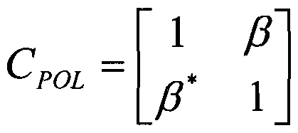
[0053] Using the Kronecker model, the SCF matrix R can be represented using five parameters denoted , β, p, η and δ:
Equation 3: R ~ RpoL
Figure imgf000013_0002
wherein RpoL R jLA mQ given b
Equation 4: RuLA —
Figure imgf000013_0003
[0054] Module 64 typically estimates these five parameters and then reports them as feedback information to BS 24 using uplink transmitter 68. Module 64 can estimate the five parameters a, β, p, η and δ in various ways. In an example embodiment, module 64 evaluates the following expectations over time and frequency:
Equation 5: a = (h2 *h2 + lh^/ihl^ + /I3 /I3 )
P = (h*h2 + h3 * h4)/(h1 *h1 + h3 * h3)
Figure imgf000013_0004
[0055] In order to calculate the inter-polarization and intra-polarization feedback at different time/frequency granularities, module 64 evaluates the expectations in Equation 5 above over different time/frequency ranges. In an embodiment, module 64 evaluates the expectations in a and β over larger bandwidth and/or longer time, and the expectations in p, η and δ over smaller bandwidth and/or shorter time. Then, the estimated parameters , β, p, η and δ are fed back using transmitter 68 at time/frequency granularities that match the bandwidths and time intervals over which they were evaluated.
[0056] Let the time and frequency granularities for the intra-polarization (ULA) feedback be denoted Tl and BW1, respectively. Let the time and frequency granularities for the inter-polarization (POL) feedback be denoted T2 and BW2, respectively. Using this notation, Equation 5 can be written as:
Equation 6: α, β = ( ) TI,BWI /( ) TI,BWI
Ρ' Ή = ( )T2,BW2 ,BW2
δ — ( ) T2,BW2
wherein the expectations in Equation 6 are evaluated over the corresponding terms in Equation 5 above.
[0057] Note that the normalization factor δ is related to the overall signal power, which often varies strongly with frequency and time. Therefore, although this normalization factor does not contain inter-polarization terms, it is added to the feedback information that is calculated and fed back at fine time/frequency granularity. Note also that δ does not affect the precoding, and therefore it is not regarded as part of the precoding-related feedback.
[0058] The above parameterization and parameter estimation example refers to a configuration of four transmit antennas. In alternative embodiments, this technique can be generalized in a straightforward manner to any other suitable number of transmit antennas, such as the eight antenna configuration of Fig. 1 above.
[0059] For eight receive antennas, the intra-polarization feedback (ULA) is described by three real and six complex values. The inter-polarization feedback (POL), excluding δ, is described by only a single real value (p) and a single complex value (η). If, for example, Tl is a hundred times longer than T2 and BW1 is ten times wider than BW2, the intra-polarization feedback is reduced by a factor of 1000, and the total feedback overhead is reduced from eighteen to three real values per T2 interval and BW2-wide frequency sub-band.
[0060] In alternative embodiments, e.g., when using more than two transmit antennas, module 64 may describe RULA using any other suitable parameterization scheme. Example schemes are described in 3GPP TSG RAN document Rl -94844, cited above.
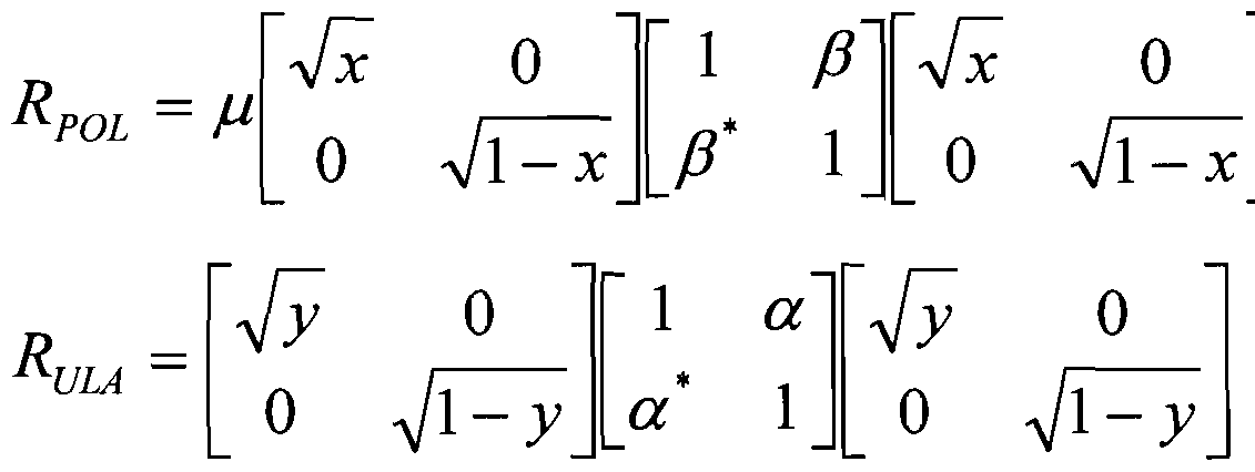
[0061] The following description explains yet another example of a parameterization and estimation scheme that can be used by module 64 for calculating the inter-polarization and intra-polarization feedback in a SCF-based feedback scheme. Without loss of generality, Equation 2 above can be written as: Equation 7: RuLA
Figure imgf000015_0001
[0062] Each of the covariance matrices in Equation 7 can be written as the product of its correlation matrix and the corresponding magnitude matrix:
Equation 8:
Figure imgf000015_0002
The correlation matrices are of the form:
1 a
Equation 9: c ^ULA =
a 1
Figure imgf000015_0003
wherein | α| J β| <1. The corresponding magnitude matrices are given by:
0
ax + a2
Equation 10: MULA = (a, + a2 )
a,
0 1 - a + a2
Figure imgf000015_0004
[0063] Substituting the above matrices into the expression for the covariance matrix R gives:
Equation 11 : R = M° 5CM° 5
wherein μ denotes a scalar parameter of the estimator, and C and are given by:
Equation 12: C— C Pol ®
Figure imgf000015_0005
Figure imgf000016_0001
[0064] In this embodiment, module 64 estimates and feeds back parameters μ, x, y, a and β. In an example embodiment, module 64 estimates an empirical (measured) covariance matrix denoted Remp. Module 64 decomposes this matrix into a normalized correlated form: Equation 13: ^emp = trace{Remp)M^pCempM^p wherein M emp = diag (m x , m 2 , m3 , m 4 ) , mk≤i, and ^emp— icij } .
[0065] In some embodiments, module 64 estimates parameters μ, x, y, a and β by numerically solving the expression:
Equation 14:
{μ, x, y, a, β) OPT arg mm x, y, a, ) - R emp
[0066] Module 64 may apply any suitable numerical method for this purpose, such as various gradient descent and fixed-point iteration methods.
[0067] In an alternative embodiment, module 64 exploits the normalized decomposition of the covariance matrix into a correlation component and a magnitude component to simplify the parameter estimation. In this embodiment, the optimization problem is given by:
Equation 15:
Figure imgf000016_0002
+ .
μ = trace (Remp )
[0068] In yet another embodiment, module 64 estimates parameters μ, x, y, a and β by evaluating:
Equation 16: μ = trace (Remp ) ' 12 + C 34
β = a C13 + C24 x = mx + m2
y = ml + m3
[0069] The latter scheme involves only simple computations such as addition and multiplication, which simplifies implementation in UE 28. This scheme is also computationally robust since it does not involve nonlinearities.
[0070] In an embodiment, upon receiving the above-described feedback in BS 24, BS processor 32 reconstructs the covariance matrix R by evaluating:
Equation 17:
Figure imgf000017_0001
[0071] In some embodiments, system 20 uses implicit, PMI-based feedback. In these embodiments, BS 24 and UE 28 use a predefined codebook of precoding matrices. Each precoding matrix in the codebook has a corresponding index, and the UE feedback comprises an index of the preferred precoding matrix (PMI). In order to partition the feedback into an intra-polarization part and an inter-polarization part, in some embodiments the codebook is represented as a Kronecker product of two sub-codebooks. In these embodiments, the precoding matrices in the codebook are constrained to have the form:
Equation 18: V— V pQi ® ^ULA wherein V oi denotes a precoding matrix corresponding to pairs of antennas in which the antennas in each pair have orthogonal polarizations, and VJJLA denotes a precoding matrix corresponding to pairs of antennas in which both antennas in each pair have the same polarization.
[0072] Certain aspects of precoding codebooks that are constructed using Kronecker products are also addressed in U.S. Patent Application Serial Number 12/652,044, which is assigned to the assignee of the present patent application and whose disclosure is incorporated herein by reference in its entirety, and in 3GPP TSG RAN documents Rl -94686 and Rl- 903888, cited above.
[0073] Typically, module 64 calculates VpQi, and transmitter 68 feeds back Vp i, at a relatively fine time/frequency granularity (e.g., T2/BW2). On the other hand, module 64 calculates VJJ ^, and transmitter 68 feeds back VJJ^, at a relatively coarse time/frequency granularity (e.g., T1/BW1). Upon receiving a certain VpoL feedback at BS 24, the equality in
Equation 18 holds assuming VJIA has already been chosen.
[0074] Module 64 may choose the preferred VJIA matrix using any suitable method.
In an example embodiment, module 64 conducts an exhaustive search for the optimal VJI^. Consider, for example, a scenario in which T1=T2 and BW1»BW2. In an embodiment, module 64 evaluates all possible VJJI^ matrices and chooses the preferred matrix without introducing delay. When T1»T2, module 64 can maintain the first VJJLA matrix that was chosen by the exhaustive search on the first T2 interval within Tl .
[0075] In an alternative embodiment, module 64 searches at a given time and frequency instant both for the preferred VpoL matrix (under the constraint of a previously- chosen VUIA matrix), and for an optimal
Figure imgf000018_0001
matrix pair. The current VpoL feedback comprises the former (preferred VpoL assuming a previously-chosen VJJI ), but the chosen Vrji indices from the latter (optimal
Figure imgf000018_0002
pair) is stored in memory. When an update of VJJ ^ is carried out, the update is determined by performing a majority vote between the indices stored in memory.
[0076] In another alternative embodiment, module 64 estimates R jLA as described in Equation 4 above, and then determines VJJU^ using Singular Value Decomposition (SVD). This technique is useful, for example, in scenarios where BS 24 assumes reciprocity between the uplink and downlink channels for inter-polarization precoding, so that VJJLA does not have to be quantized. If VJJI^ does need to be quantized for feedback, quantization according to any suitable metric, e.g., Chordal distance, can be used. [0077] The description above refers to codebooks in which all precoding matrices are structured according to the form of Equation 18. In alternative embodiment, only a subset of the precoding matrices in the codebook are structures in this form, and one or more of the precoding matrices in the codebook are free of this constraint.
[0078] In some embodiments, system 20 uses eigenvalue/eigenvector-based feedback. In these embodiments, module 64 in UE 28 calculates and feeds back one or more eigenvalues and/or eigenvectors of the channel covariance matrix R. Matrix R can be written as:
Equation 19: R = VDV H wherein V and D denote eigen-matrices, such that V is unitary and D is diagonal. Matrices V and D can be represented using Kronecker products of inter-polarization and intra-polarization matrices:
Figure imgf000019_0001
[0079] In an embodiment, module 64 chooses and feeds back the optimal Vj u at a relatively coarse time/frequency granularity, and selects and feeds back VPQL at a relatively fine time/frequency granularity under the constraint that
Figure imgf000019_0002
has already been selected. If the eigenvalue-based feedback is quantized by a codebook, then, similar to the PMI-based embodiments, this codebook should have the structure of Equation 12 above.
[0080] Module 64 may parameterize and report the inter-polarization and intra- polarization parts of V and D in any suitable way. The following description gives an example parameterization and estimation scheme. In a cross-polarized antenna array of 2N transmit antennas, the V and D matrices associated with the inter-polarization (POL) feedback are 2-by- 2 matrices, whereas the V and D matrices associated with the intra-polarization (ULA) feedback are N-by-N matrices. Thus, for four transmit antennas, all the V and D matrices are 2-by-2 matrices, and therefore the unitary V and the diagonal D matrices can generally be represented as:
Equation 21:
Figure imgf000019_0003
Figure imgf000020_0001
wherein 0≤θ<π, 0<ε<1, and assuming the convention that the first column of matrix V corresponds to the stronger eigenvector (i.e., the eigenvector having the larger eigenvalue).
The general form for either RpoL or ^ULA becomes:
Figure imgf000020_0002
Equation 22: 2x2 e~j(ps s . l - scos
[0081] Using Equation 21 above, the ULA and POL eigen-matrices can be written explicitly as:
cos a
Equation 23: V ULA = -j-β sin or —e ^ cosa cosy smy
Pol
e JJ] s\ny - e J7? cosy
Ι + ε 0
DULA =
0 Ι - ε
Figure imgf000020_0003
wherein 0<ο≤π/2, 0≤γ≤π/2, and whereing the total normalization factor μ is embedded in POI.
[0082] The eigenvalue representation of R can thus be written as:
Equation 24:
Figure imgf000020_0004
whereing Trace(£>)=4/., and where (1+£·)·(1 + ν) denotes the largest eigenvalue. The eigenvector matrix is given by:
Equation 24:
Figure imgf000021_0001
wherein A, B, C, E are real positive values and Φ is a 2-by-2 matrix whose left-most column refers to the strongest eigenvector:
Equation 25: = COS a COS 11
B = sin a sin γ Φ22 = ρ
C = cos a sin γ
E = sin a cos γ
[0083] Note that ε and v are defined to be positive, and therefore the largest eigenvalue in Equation 24 is the top-left eigenvalue. The strongest eigenvector, denoted V\, is thus given by:
Equation 26:
Γ cos a cos γ
Figure imgf000021_0002
wherein Ψ\ is the first column of Ψ.
[0084] The diagonal of matrix R is given by:
Equation 27:
1 + ε cos(2a))(l + v cos(2^))
1 - ε cos(2a))(l + v cos(2^))
diagR = diag(RPol 0 RULA ) = μ
1 + ε cos(2a))(l - v cos(2^))
l - ε cos(2a))(l - v cos(2^))
[0085] In some embodiments, module 64 computes an empirical covariance matrix Remp averaging over a certain time/frequency range, and decomposing the averaged matrix according to: Equation 28: i emp y empLJ mpv emp
[0086] In various embodiments, module 64 estimates the four parameters {a, β, γ, η) from any one of the four eigenvectors, or from some optimal combination of them. In an example embodiment, module 64 uses only the strongest eigenvector for estimation, since the contribution of the weaker eigenvectors is typically noisier. Moreover, as explained further below, there is ambiguity in the SVD components with regard to their column order, which may complicate the estimation process. Using only the strongest eigenvector eliminates this ambiguity. In this embodiment, module 64 identifies the strongest eigenvector V -emp of the empirical covariance matrix. Module 64 cancels any redundant phase (that is inherent in the SVD) by the following normalization so as to ensure the top element is real -positive:
Equation 29:
Figure imgf000022_0001
[0087] Module 64 estimates β and η by:
Equation 30:
Φ,.
Figure imgf000022_0002
ή = (Φ,3 + [(Φ« - β)( οά 2π)] / 2
[0088] Module 64 estimates a and yby: Equation 31: V\
[0089] Module 64 obtains the values of ο&γ and α-γ by (the left-hand-sides of the following equation should be regarded as composite symbol names and not products of single- letter variables):
Equation 32: Ctpyc = COS-1 ( (1) - ^ (4))
ap s = sin-1 (Φ. (2) + Ψ. (3))
ccmyc = cos"1 (Ψ^Ι) + ^ (4)) am^ - sin-1( 1(2) - l 1(3))
[0090] In an embodiment, module 64 then averages the terms cos lQ and sin lQ after resolving the ambiguity of the sin l() function. Alternatively, module 64 uses only the cos l() term, sacrificing some Signal to Noise Ratio (SNR) gain: Equation 33: ί |θ ~ Cpys) ~
Figure imgf000023_0001
apys— π— apys
Figure imgf000023_0002
amys = π - amys opy = j (apyc + apys) amy— {amyc + amys) a = {apy + amy) y = apy - a
[0091] In an embodiment, module 64 begins the estimation of the eigenvalues of the inter-polarization and intra-polarization parts by calculating:
Equation 34: M = Tr(Demp ) / 4
[0092] The elements of Demp may require sorting in order to identify them with the matrix elements in Equation 12 above. By definition, the largest element corresponds to (1+£·)·(1 + ν), and the smallest element corresponds to (l-£) (l-v). However, there is no guarantee as to which of the two remaining elements corresponds to (1-έ)·(1+ν) and which to (1+£·)·(1-ν). In an embodiment, module 64 therefore tests the two hypotheses and chooses the one that exhibits the best fit between the empirical and modeled R.
[0093] For the first hypothesis, ε> v, module 64 evaluates:
Equation 35: D = /μ Demp ([4,2,3, [4,2,3,l]) sl = (Du + D ) - l s2 = -±(D22 + D44 ) + \
Figure imgf000024_0001
v2 = - (D +Du) + \
Figure imgf000024_0002
[0094] For the second hypothesis, £< v, module 64 evaluates: Equation 36: D = /μ Demp ([4,3,2,l], [4,3,2,l])
s\ = ±(Du+D33)-l
El = - {b22+D„) + \
Figure imgf000024_0003
v\ = (bn+D22)-\
v2 = - ( ^+b^) + \
v2= {v\ + v2)
[0095] Module 64 then computes the Euclidean distance between diag(R) and diag(Remp) under the two hypotheses, and selects the hypothesis resulting in the smaller distance. In other words, we define:
Equation 37:
Figure imgf000024_0004
wherein i=\,2 denotes the hypothesis index, and the winning hypothesis is the one producing the smallest d.
[0096] In some embodiments, module 64 carries out a two-stage process that calculates the intra-polarization feedback at coarse granularity and the inter-polarization feedback at fine granularity. In an embodiment, module 64 computes a long-term empirical R
(denoted by RWB) by averaging over a relatively long time and (possibly) wideband frequency sub-bands. Module 64 then follows the above-described process to estimate , β, and f from R YB- The estimated values are denoted αψβ, βψΒ anci £WB> respectively. Module 64 further computes a short-term empirical R (denoted R$B) by averaging over a relatively short time and (possibly) narrowband frequency sub-bands. Module 64 repeats the above-described process to estimate γ,η, and v from R$B-
[0097] In the latter process, however, the calculation of ή in Equation 30, the calculation of γ in Equation 33 and the calculation of d\ in Equation 37 are replaced by:
Equation 38:
ή = [(φ33 +44 - Β)(πιοά 2π)] / 2
γ - αργ - a
Figure imgf000025_0001
[0098] When implementing the disclosed techniques, BS 24 is typically configured to receive the inter-polarization and intra-polarization feedback at different time/frequency granularities, and to combine the two feedback types. In some embodiments, the time/frequency granularity for each feedback type is configurable, e.g., set by the BS and signaled to the UE.
[0099] When implementing the disclosed techniques, in an embodiment the BS and UE use an agreed convention with regard to indexing the transmit antennas. The disclosed techniques can be used with any suitable antenna indexing scheme. For an eight-antenna configuration, for example, in one scheme antennas A1 ,A2,A3,A4 have one polarization, and antennas A5,A6,A7,A8 have the orthogonal polarization. This scheme was used in the examples above. In another scheme, antennas A2,A4,A6,A8 have one polarization, and antennas A1 ,A3,A5,A7 have the orthogonal polarization. The second scheme can be defined irrespective of the number of antennas: One set comprises the even-order antennas and the other set comprises the odd-order antennas. When using this indexing scheme with Kronecker- based partitioning of the feedback, the order of multiplication in the Kronecker product should be reversed (e.g., to RuLA®RpOL m Equation 2, and to Vuu®VpQ in Equation 18). [0100] It is noted that the embodiments described above are cited by way of example, and that the present invention is not limited to what has been particularly shown and described hereinabove. Rather, the scope of the present invention includes both combinations and sub-combinations of the various features described hereinabove, as well as variations and modifications thereof which would occur to persons skilled in the art upon reading the foregoing description and which are not disclosed in the prior art.

Claims

1. A method, comprising:
receiving a Multiple-Input Multiple Output (MIMO) signal over multiple communication channels from an antenna array including a first set of antennas having a first polarization and a second set of the antennas having a second polarization that is orthogonal to the first polarization;
calculating first feedback information relating to first interrelations between the antennas within either the first set or the second set;
calculating second feedback information relating at least to second interrelations between the first set and the second set of the antennas; and
transmitting the first feedback information at a first time/frequency granularity, and transmitting the second feedback information at a second time/frequency granularity that is finer than the first time/frequency granularity.
2. The method according to claim 1, wherein calculating the first and second feedback information comprises calculating a feedback matrix, which is represented as a Kronecker product of a first matrix depending on the first interrelations and a second matrix depending on the second interrelations.
3. The method according to claim 2, wherein transmitting the first and second feedback information comprises reporting the first matrix at the first time/frequency granularity and reporting the second matrix at the second time/frequency granularity.
4. " The method according to claim 2, wherein calculating the feedback matrix comprises estimating elements of a Spatial Correlation Function (SCF) matrix.
5. The method according to claim 2, wherein calculating the feedback matrix comprises selecting a precoding matrix to be applied for subsequent transmission of the MIMO signal.
6. The method according to claim 5, wherein selecting the precoding matrix comprises choosing the precoding matrix from a predefined set of precoding matrices, at least some of which are represented as Kronecker products of respective first matrices depending on the first interrelations and respective second matrices depending on the second interrelations.
7. The method according to claim 1 or 2, wherein transmitting the first and second feedback information at the first and second time/frequency granularities comprises transmitting only the second feedback information and not the first feedback information.
8. The method according to claim 1 or 2, wherein calculating the second feedback comprises computing the second feedback based on at least one additional feedback parameter, which depends on one or more of the antennas in the first set and one or more of the antennas in the second set.
9. The method according to claim 1 or 2, wherein calculating the first feedback information comprises computing the first feedback information over first time intervals and over first frequency bands, and wherein calculating the second feedback information comprises computing the second feedback information over second time intervals that are shorter than the first time intervals, and over second frequency bands that are narrower than the first frequency bands.
10. Apparatus, comprising:
a receiver, which is configured to receive a Multiple-Input Multiple Output (MIMO) signal over multiple communication channels from an antenna array including a first set of antennas having a first polarization and a second set of the antennas having a second polarization that is orthogonal to the first polarization;
a processor, which is configured to calculate first feedback information relating to first interrelations between the antennas within either the first set or the second set, and to calculate second feedback information relating at least to second interrelations between the first set and the second set of the antennas; and
a transmitter, which is configured to transmit the first feedback information at a first time/frequency granularity, and to transmit the second feedback information at a second time/frequency granularity that is finer than the first time/frequency granularity.
1 1. The apparatus according to claim 10, wherein the processor is configured to calculate the first and second feedback information by calculating a feedback matrix, which is represented as a Kronecker product of a first matrix depending on the first interrelations and a second matrix depending on the second interrelations.
12. The apparatus according to claim 11, wherein the transmitter is configured to report the first matrix at the first time/frequency granularity and to report the second matrix at the second time/frequency granularity.
1 . The apparatus according to claim 11, wherein the processor is configured to calculate the feedback matrix by estimating elements of a Spatial Correlation Function (SCF) matrix.
14. The apparatus according to claim 1 1 , wherein the processor is configured to calculate the feedback matrix by selecting a precoding matrix to be applied for subsequent transmission of the MIMO signal.
15. The apparatus according to claim 14, wherein the processor is configured to choose the precoding matrix from a predefined set of precoding matrices, at least some of which are represented as Kronecker products of respective first matrices depending on the first interrelations and respective second matrices depending on the second interrelations.
16. The apparatus according to claim 10 or 11, wherein the transmitter is configured to transmit only the second feedback information and not the first feedback information.
17. The apparatus according to claim 10 or 11, wherein the processor is configured to compute the second feedback based on at least one additional feedback parameter, which depends on one or more of the antennas in the first set and one or more of the antennas in the second set.
18. A mobile communication terminal comprising the apparatus of claim 10.
19. A chipset for processing signals in a mobile communication terminal, comprising the apparatus of claim 10.
20. Apparatus, comprising:
an antenna array, which comprises a first set of antennas having a first polarization and a second set of the antennas having a second polarization that is orthogonal to the first polarization;
a transmitter, which is configured to transmit a Multiple-Input Multiple Output (MIMO) signal over multiple communication channels using the antenna array;
a receiver, which is configured to receive, at a first time/frequency granularity, first feedback information relating to first interrelations between the antennas within either the first set or the second set, and to receive, at a second time/frequency granularity that is finer than the first time/frequency granularity, second feedback information relating at least to second interrelations between the first set and the second set of the antennas; and
a processor, which is configured to combine the first and second feedback information received respectively at the first and second time/frequency granularities, and to adapt transmission of the MIMO signal based on the combined first and second feedback.
PCT/IB2010/055763 2009-12-17 2010-12-12 Mimo feedback schemes for cross-polarized antennas WO2011073876A2 (en)

Priority Applications (3)

Application Number Priority Date Filing Date Title
CN201080057652.9A CN102783120B (en) 2009-12-17 2010-12-12 MIMO feedback schemes for cross-polarized antennas
EP10837147.7A EP2514181B1 (en) 2009-12-17 2010-12-12 Mimo feedback schemes for cross-polarized antennas
JP2012543960A JP5637486B2 (en) 2009-12-17 2010-12-12 MIMO feedback scheme for cross-polarized antennas

Applications Claiming Priority (4)

Application Number Priority Date Filing Date Title
US28765209P 2009-12-17 2009-12-17
US61/287,652 2009-12-17
US29400010P 2010-01-11 2010-01-11
US61/294,000 2010-01-11

Publications (2)

Publication Number Publication Date
WO2011073876A2 true WO2011073876A2 (en) 2011-06-23
WO2011073876A3 WO2011073876A3 (en) 2011-08-11

Family

ID=44151041

Family Applications (1)

Application Number Title Priority Date Filing Date
PCT/IB2010/055763 WO2011073876A2 (en) 2009-12-17 2010-12-12 Mimo feedback schemes for cross-polarized antennas

Country Status (5)

Country Link
US (1) US8761289B2 (en)
EP (1) EP2514181B1 (en)
JP (1) JP5637486B2 (en)
CN (1) CN102783120B (en)
WO (1) WO2011073876A2 (en)

Cited By (3)

* Cited by examiner, † Cited by third party
Publication number Priority date Publication date Assignee Title
JP2013517647A (en) * 2010-01-12 2013-05-16 ゼットティーイー コーポレーション Method and system for spatial channel state information feedback based on Kronecker product
WO2013068915A3 (en) * 2011-11-07 2015-08-06 Marvell World Trade Ltd. Precoding feedback for cross-polarized antennas with magnitude information
JP2017509280A (en) * 2014-03-06 2017-03-30 アルカテル−ルーセント Method and apparatus for quantizing channel state information

Families Citing this family (48)

* Cited by examiner, † Cited by third party
Publication number Priority date Publication date Assignee Title
KR101673497B1 (en) 2009-01-05 2016-11-07 마벨 월드 트레이드 리미티드 Precoding codebooks for mimo communication systems
US8385441B2 (en) 2009-01-06 2013-02-26 Marvell World Trade Ltd. Efficient MIMO transmission schemes
US8238483B2 (en) 2009-02-27 2012-08-07 Marvell World Trade Ltd. Signaling of dedicated reference signal (DRS) precoding granularity
WO2011055238A1 (en) 2009-11-09 2011-05-12 Marvell World Trade Ltd Asymmetrical feedback for coordinated transmission systems
PT2522094E (en) * 2010-01-08 2015-07-17 Huawei Tech Co Ltd Reporting of channel state information
EP2529489B1 (en) * 2010-01-27 2018-10-17 Telefonaktiebolaget LM Ericsson (publ) Closed loop precoding weight estimation
JP5258002B2 (en) 2010-02-10 2013-08-07 マーベル ワールド トレード リミテッド Device, mobile communication terminal, chipset, and method in MIMO communication system
KR101615927B1 (en) * 2010-06-22 2016-05-12 삼성전자주식회사 Multi-user mimo communication system considering feedback loss
US8615052B2 (en) * 2010-10-06 2013-12-24 Marvell World Trade Ltd. Enhanced channel feedback for multi-user MIMO
JP2012100254A (en) 2010-10-06 2012-05-24 Marvell World Trade Ltd Codebook subsampling for pucch feedback
CN102594419B (en) * 2011-01-04 2015-03-04 上海贝尔股份有限公司 Precoding method and precoder used for cross polarized antenna array
US9048970B1 (en) 2011-01-14 2015-06-02 Marvell International Ltd. Feedback for cooperative multipoint transmission systems
US8861391B1 (en) 2011-03-02 2014-10-14 Marvell International Ltd. Channel feedback for TDM scheduling in heterogeneous networks having multiple cell classes
WO2012131612A1 (en) 2011-03-31 2012-10-04 Marvell World Trade Ltd. Channel feedback for cooperative multipoint transmission
US20130115886A1 (en) * 2011-11-04 2013-05-09 Samsung Electronics Co., Ltd. Apparatus and method for polarization alignment in a wireless network
WO2013068916A1 (en) * 2011-11-07 2013-05-16 Marvell World Trade Ltd. Codebook sub-sampling for frequency-selective precoding feedback
US9031597B2 (en) 2011-11-10 2015-05-12 Marvell World Trade Ltd. Differential CQI encoding for cooperative multipoint feedback
FR2983666B1 (en) * 2011-12-01 2014-01-03 Cassidian Sas METHOD OF ESTIMATING A RADIO CHANNEL
US9220087B1 (en) 2011-12-08 2015-12-22 Marvell International Ltd. Dynamic point selection with combined PUCCH/PUSCH feedback
US9590709B2 (en) 2011-12-23 2017-03-07 Nokia Solutions And Networks Oy Methods, apparatuses, and computer-readable storage media for performing multidimensional beamforming
US8902842B1 (en) 2012-01-11 2014-12-02 Marvell International Ltd Control signaling and resource mapping for coordinated transmission
KR102109655B1 (en) 2012-02-23 2020-05-12 한국전자통신연구원 Method for multi-input multi-output communication in a large-scale antenna system
US20150078472A1 (en) * 2012-03-30 2015-03-19 Nokia Solutions And Networks Oy Feedback Methodology for Per-User Elevation MIMO
US9143951B2 (en) 2012-04-27 2015-09-22 Marvell World Trade Ltd. Method and system for coordinated multipoint (CoMP) communication between base-stations and mobile communication terminals
US9520914B2 (en) * 2012-06-25 2016-12-13 Samsung Electronics Co., Ltd. Full-duplex wireless communication system using polarization
US8983002B2 (en) 2012-10-02 2015-03-17 Broadcom Corporation Systems and methods for establishing transmission format parameters between communication devices
CN103812545B (en) * 2012-11-06 2018-11-16 上海诺基亚贝尔股份有限公司 The feedback method and device of channel state information
GB2509958B (en) * 2013-01-18 2016-02-03 Broadcom Corp Methods, apparatus and computer programs for controlling feedbck about channel conditions
KR101978776B1 (en) 2013-02-28 2019-05-16 삼성전자주식회사 Method and apparatus for transmitting and receivintg feedback information in mobile communication system based on full dimension mimo
EP2974134A4 (en) * 2013-03-15 2016-08-03 Hewlett Packard Development Co Energy based network restructuring
JP2014204305A (en) * 2013-04-05 2014-10-27 株式会社Nttドコモ Radio communication system, radio base station and user device
JP6199653B2 (en) * 2013-08-06 2017-09-20 株式会社Nttドコモ Wireless communication system and antenna configuration determination method
US9312944B2 (en) 2013-12-26 2016-04-12 Aruba Networks, Inc. System, apparatus and method for integrated wireless link management for a multi-polarized antenna system
EP3103293B1 (en) 2014-02-14 2022-12-14 Huawei Technologies Co., Ltd. Base station, mobile station and method thereof
CN103929280B (en) * 2014-03-31 2017-06-23 电信科学技术研究院 The generation method and device and code book feedback method and device of multi-stage codebooks
EP3281301B1 (en) * 2015-04-09 2020-06-03 Telefonaktiebolaget LM Ericsson (publ) Efficient channel characteristics handling
KR20180009776A (en) 2015-06-23 2018-01-29 후지쯔 가부시끼가이샤 Wireless communication control method, wireless communication system, receiving apparatus and transmitting apparatus
CN106341167B (en) * 2015-07-15 2019-09-03 上海诺基亚贝尔股份有限公司 A kind of method and apparatus carrying out cell splitting in the sector eNB
CN112088497B (en) * 2018-05-09 2023-07-07 索尼集团公司 Method and device for polarization optimization of MIMO wireless transmission
US10673500B2 (en) 2018-06-25 2020-06-02 Qualcomm Incorporated Hybrid closed-loop multiple-input multiple-output and transparent diversity schemes
US10785695B1 (en) * 2019-02-19 2020-09-22 Sprint Spectrum L.P. System and method for managing data throughput of wireless devices in a wireless network
US11824637B2 (en) 2019-05-22 2023-11-21 At&T Intellectual Property I, L.P. Generating wireless reference signals in a different domain for transmission
US10886991B2 (en) * 2019-05-22 2021-01-05 At&T Intellectual Property I, L.P. Facilitating sparsity adaptive feedback in the delay doppler domain in advanced networks
US10979151B2 (en) 2019-05-22 2021-04-13 At&T Intellectual Property I, L.P. Multidimensional grid sampling for radio frequency power feedback
US11050530B2 (en) 2019-06-27 2021-06-29 At&T Intellectual Property I, L.P. Generating wireless reference signals in a different domain for transmission with a collapsed time-frequency grid
WO2021018402A1 (en) 2019-08-01 2021-02-04 Huawei Technologies Co., Ltd. Adaptive kronecker product mimo precoding for a multi-antenna network entity and a wireless communication device and corresponding methods
CN111917671B (en) * 2020-08-07 2023-11-14 北京信息科技大学 Apparatus and method for wireless communication
US11646506B2 (en) * 2020-12-30 2023-05-09 Qualcomm Incorporated Techniques for beam-specific phase adjustment in non-co-located dual-polarized antenna arrays

Citations (1)

* Cited by examiner, † Cited by third party
Publication number Priority date Publication date Assignee Title
US20080094281A1 (en) 2006-10-24 2008-04-24 Nokia Corporation Advanced codebook for multi-antenna transmission systems

Family Cites Families (201)

* Cited by examiner, † Cited by third party
Publication number Priority date Publication date Assignee Title
US5231629A (en) * 1990-10-01 1993-07-27 Motorola, Inc. Full-duplex communication system
US5263160A (en) * 1991-01-31 1993-11-16 Digital Equipment Corporation Augmented doubly-linked list search and management method for a system having data stored in a list of data elements in memory
US5349567A (en) * 1993-08-24 1994-09-20 Hughes Aircraft Company Least mean square (LMS) normalizer for active sonar
AU4238697A (en) * 1996-08-29 1998-03-19 Cisco Technology, Inc. Spatio-temporal processing for communication
US5940439A (en) * 1997-02-26 1999-08-17 Motorola Inc. Method and apparatus for adaptive rate communication system
US6354733B2 (en) * 1999-01-15 2002-03-12 Ametex, Inc. System and method for determining combustion temperature using infrared emissions
US6512750B1 (en) * 1999-04-16 2003-01-28 Telefonaktiebolaget Lm Ericsson (Publ) Power setting in CDMA systems employing discontinuous transmission
US6757319B1 (en) * 1999-11-29 2004-06-29 Golden Bridge Technology Inc. Closed loop power control for common downlink transport channels
US6865237B1 (en) * 2000-02-22 2005-03-08 Nokia Mobile Phones Limited Method and system for digital signal transmission
US6466904B1 (en) * 2000-07-25 2002-10-15 Conexant Systems, Inc. Method and apparatus using harmonic modeling in an improved speech decoder
US6785341B2 (en) * 2001-05-11 2004-08-31 Qualcomm Incorporated Method and apparatus for processing data in a multiple-input multiple-output (MIMO) communication system utilizing channel state information
JP4084947B2 (en) * 2002-02-15 2008-04-30 ソフトバンクテレコム株式会社 CDMA base station apparatus
EP1481354A2 (en) * 2002-03-05 2004-12-01 BAE Systems PLC Expertise modelling
US7502432B2 (en) * 2003-07-09 2009-03-10 Broadcom Corporation Weight generation method for multi-antenna communication systems utilizing RF-based and baseband signal weighting and combining based upon minimum bit error rate
US7336746B2 (en) 2004-12-09 2008-02-26 Qualcomm Incorporated Data transmission with spatial spreading in a MIMO communication system
SE0400370D0 (en) 2004-02-13 2004-02-13 Ericsson Telefon Ab L M Adaptive MIMO architecture
US7346115B2 (en) * 2004-04-22 2008-03-18 Qualcomm Incorporated Iterative eigenvector computation for a MIMO communication system
US20050250544A1 (en) * 2004-05-07 2005-11-10 Stephen Grant Base station, mobile terminal device and method for implementing a selective-per-antenna-rate-control (S-PARC) technique in a wireless communications network
US8085831B2 (en) 2004-05-17 2011-12-27 Qualcomm Incorporated Interference control via selective blanking/attenuation of interfering transmissions
JP4616338B2 (en) * 2004-06-14 2011-01-19 サムスン エレクトロニクス カンパニー リミテッド Apparatus, system and method for controlling transmission mode in a mobile communication system using multiple transmit / receive antennas
US8116262B2 (en) * 2004-06-22 2012-02-14 Rockstar Bidco Lp Methods and systems for enabling feedback in wireless communication networks
EP1617691B1 (en) * 2004-07-13 2009-09-02 Alcatel Lucent Method for terminal-assisted interference control in a multi-carrier mobile communication system
US7978649B2 (en) 2004-07-15 2011-07-12 Qualcomm, Incorporated Unified MIMO transmission and reception
KR101151130B1 (en) * 2004-08-17 2012-06-04 삼성전자주식회사 Method and apparatus for transmitting and receiving data using full rate full diversity stbc
KR20060038812A (en) * 2004-11-01 2006-05-04 엘지전자 주식회사 Method for transmitting precoding matrix and transmitting signal using the precoding matrix
KR20060043035A (en) * 2004-11-02 2006-05-15 삼성전자주식회사 Improved mimo system and method
CN101099326B (en) * 2004-11-16 2012-10-03 高通股份有限公司 Closed-loop rate control for a mimo communication system
US7428268B2 (en) * 2004-12-07 2008-09-23 Adaptix, Inc. Cooperative MIMO in multicell wireless networks
RU2369027C2 (en) * 2005-01-11 2009-09-27 Самсунг Электроникс Ко., Лтд. Method and system for indicating assignment of data packets in wireless communication system
JP4832087B2 (en) * 2005-01-26 2011-12-07 パナソニック株式会社 Radio base station apparatus and terminal apparatus
KR100922958B1 (en) * 2005-03-14 2009-10-22 삼성전자주식회사 Apparatus and method for user assigning in a mimo wireless system serving multi-user diversity
US9408220B2 (en) * 2005-04-19 2016-08-02 Qualcomm Incorporated Channel quality reporting for adaptive sectorization
WO2006117665A1 (en) 2005-05-04 2006-11-09 Nortel Networks Limited Wireless feedback system and method
DE602005027822D1 (en) * 2005-05-25 2011-06-16 Mitsubishi Electric Corp Encoding matrix in a MIMO system
US7428269B2 (en) * 2005-06-01 2008-09-23 Qualcomm Incorporated CQI and rank prediction for list sphere decoding and ML MIMO receivers
EP1938485A4 (en) * 2005-09-20 2015-04-22 Maxtech Networks Ltd Real time peer to peer network
US20070076810A1 (en) * 2005-09-30 2007-04-05 Herrera Alfonso R System and method for selecting transmission format using effective SNR
US20070165738A1 (en) * 2005-10-27 2007-07-19 Barriac Gwendolyn D Method and apparatus for pre-coding for a mimo system
US20070099578A1 (en) * 2005-10-28 2007-05-03 Kathryn Adeney Pre-coded diversity forward channel transmission system for wireless communications systems supporting multiple MIMO transmission modes
KR20070108304A (en) * 2005-10-31 2007-11-09 삼성전자주식회사 Method and apparatus for transmitting/receiving of channel quality imformation in multi antenna system
WO2007074376A2 (en) * 2005-12-27 2007-07-05 Nokia Corporation Priority based transmission based on channel quality using power sequencing
US9071435B2 (en) 2005-12-29 2015-06-30 Celeno Communications Ltd. System and method for tuning transmission parameters in multi-user multiple-input-multiple-output systems with aged and noisy channel estimation
US20070153731A1 (en) * 2006-01-05 2007-07-05 Nadav Fine Varying size coefficients in a wireless local area network return channel
KR101012553B1 (en) * 2006-02-02 2011-02-07 후지쯔 가부시끼가이샤 Radio transmitting method, radio transmitter and radio receiver
US10044532B2 (en) * 2006-03-20 2018-08-07 Texas Instruments Incorporated Pre-coder selection based on resource block grouping
US8059609B2 (en) * 2006-03-20 2011-11-15 Qualcomm Incorporated Resource allocation to support single-user and multi-user MIMO transmission
US8914015B2 (en) * 2006-03-20 2014-12-16 Qualcomm Incorporated Grouping of users for MIMO transmission in a wireless communication system
US7804800B2 (en) * 2006-03-31 2010-09-28 Intel Corporation Efficient training schemes for MIMO based wireless networks
US7751368B2 (en) * 2006-05-01 2010-07-06 Intel Corporation Providing CQI feedback to a transmitter station in a closed-loop MIMO system
KR101345868B1 (en) 2006-05-09 2014-01-15 인터디지탈 테크날러지 코포레이션 Variable feedback for universal terrestrial radio access
EP2018787B1 (en) * 2006-05-17 2017-03-08 LG Electronics Inc. A method of implementing superposition coding for a forward link in a wireless commnication system
US20150030058A9 (en) * 2006-05-17 2015-01-29 Texas Instruments Inc. Cqi feedback for mimo deployments
TWI343200B (en) 2006-05-26 2011-06-01 Lg Electronics Inc Method and apparatus for signal generation using phase-shift based pre-coding
PL2157707T3 (en) 2006-06-20 2012-12-31 Huawei Tech Co Ltd System and processor for reducing feedback information overhead in precoded MIMO-OFDM systems
KR101295576B1 (en) 2006-06-22 2013-08-09 엘지전자 주식회사 data transfer method using phase-shift based precoding and transmitter implementing the same
US7593729B2 (en) * 2006-07-13 2009-09-22 Designart Networks Ltd Point to point link and communication method
US7941186B2 (en) * 2006-07-25 2011-05-10 Samsung Electronics Co., Ltd. Apparatus and method for scheduling multiuser/single user in multiple input multiple output (MIMO) system
US7450673B2 (en) * 2006-08-10 2008-11-11 Cisco Technology, Inc. System and method for improving the robustness of spatial division multiple access via nulling
CN103986556B (en) * 2006-08-17 2019-07-02 英特尔公司 For providing the method and apparatus of effective precoding feedback in mimo wireless communication system
JP4904994B2 (en) 2006-08-25 2012-03-28 富士通東芝モバイルコミュニケーションズ株式会社 Mobile radio terminal device
KR20080022033A (en) * 2006-09-05 2008-03-10 엘지전자 주식회사 Method for feed back information concerning pre-coding and method for pre-coding
KR20080026019A (en) 2006-09-19 2008-03-24 엘지전자 주식회사 Phase shift based precoding method and tranceiver supporting the same
US8102931B2 (en) * 2006-09-29 2012-01-24 Apple Inc. Method and device for operating a precoded MIMO system
US7702029B2 (en) * 2006-10-02 2010-04-20 Freescale Semiconductor, Inc. MIMO precoding enabling spatial multiplexing, power allocation and adaptive modulation and coding
US20080080635A1 (en) * 2006-10-02 2008-04-03 Nokia Corporation Advanced feedback signaling for multi-antenna transmission systems
US8503560B2 (en) * 2006-10-02 2013-08-06 Samsung Electronics Co., Ltd System and method for performing precoding in a wireless communication system
CN101166052B (en) * 2006-10-19 2012-05-23 株式会社Ntt都科摩 Precoding method for multi-input multi-output system and apparatus using same
US7920511B2 (en) * 2006-10-31 2011-04-05 Samsung Electronics Co., Ltd. Method and system for managing channels in a wireless communication system
JP2008118411A (en) 2006-11-06 2008-05-22 Nec Corp Radio receiver
US8305948B2 (en) * 2006-11-15 2012-11-06 Qualcomm Incorporated Transmissions to multiple stations in wireless communication systems
KR100961745B1 (en) * 2006-11-27 2010-06-07 삼성전자주식회사 Apparatus and method for communicating channel information in relay wireless communication system
US20080130778A1 (en) * 2006-12-04 2008-06-05 Samsung Electronics Co., Ltd. System and method for wireless communication of uncompressed high definition video data using a transfer matrix for beamforming estimation
JP2008147792A (en) 2006-12-06 2008-06-26 Mitsubishi Electric Corp Radio communication apparatus and system, and control device
US8073069B2 (en) * 2007-01-05 2011-12-06 Apple Inc. Multi-user MIMO-SDMA for finite rate feedback systems
US8780771B2 (en) * 2007-02-06 2014-07-15 Qualcomm Incorporated Cyclic delay diversity and precoding for wireless communication
KR20080073624A (en) * 2007-02-06 2008-08-11 삼성전자주식회사 Codebook generating method for multi-polarized mimo system and device of enabling the method
US20080192852A1 (en) * 2007-02-12 2008-08-14 Mark Kent Method and system for an alternating channel delta quantizer for 2x2 mimo pre-coders with finite rate channel state information feedback
EP2899897B1 (en) 2007-02-13 2017-07-26 Telefonaktiebolaget LM Ericsson (publ) Methods and systems for combined precoding and cyclic delay diversity
KR100951089B1 (en) * 2007-02-15 2010-04-05 삼성전자주식회사 Apparatus for optionally supporting time division duplex and frequency division duplex in wireless communication system
FI20075142A0 (en) * 2007-02-26 2007-02-26 Nokia Corp Multipoint Data Transfer
US7809074B2 (en) 2007-03-16 2010-10-05 Freescale Semiconductor, Inc. Generalized reference signaling scheme for multi-user, multiple input, multiple output (MU-MIMO) using arbitrarily precoded reference signals
JP4739259B2 (en) 2007-03-19 2011-08-03 株式会社日立製作所 Wireless communication method
US8411732B2 (en) * 2007-03-21 2013-04-02 Qualcomm Incorporated Fast square root algorithm for MIMO equalization
KR101425981B1 (en) * 2007-03-21 2014-08-05 인터디지탈 테크날러지 코포레이션 Mimo wireless communication method and apparatus for transmitting and decoding resource block structures based on a dedicated reference signal mode
EP3444969B1 (en) * 2007-03-22 2020-02-19 Marvell World Trade Ltd. Variable codebook for mimo system
US8787469B2 (en) * 2007-04-04 2014-07-22 Samsung Electronics Co., Ltd. Method for codebook design and beamforming vector selection in per-user unitary rate control (PU2RC) system
PL2615785T3 (en) 2007-04-30 2018-01-31 Ericsson Telefon Ab L M Method and arrangement for adapting a multi-antenna transmission
US7965689B2 (en) * 2007-05-14 2011-06-21 Motorola Mobility, Inc. Reference sequence construction for fast cell search
US8259824B2 (en) * 2007-05-23 2012-09-04 Texas Instruments Incorporated Nested precoding codebook structures for MIMO systems
US7649831B2 (en) * 2007-05-30 2010-01-19 Samsung Electronics Co., Ltd. Multi-user MIMO feedback and transmission in a wireless communication system
US8179775B2 (en) 2007-08-14 2012-05-15 Texas Instruments Incorporated Precoding matrix feedback processes, circuits and systems
KR100938756B1 (en) * 2007-07-06 2010-01-26 엘지전자 주식회사 Method for performing cell search procedure in wireless communication system
KR100921769B1 (en) * 2007-07-12 2009-10-15 한국전자통신연구원 Method for generating downlink frame, and method for searching cell
CA2690990C (en) 2007-07-16 2016-08-23 Nortel Networks Limited Providing space division multiple access in a wireless network
KR101478362B1 (en) * 2007-08-10 2015-01-28 엘지전자 주식회사 Method for transmitting feedback data in multiple antenna system
US8798183B2 (en) * 2007-08-13 2014-08-05 Qualcomm Incorporated Feedback and rate adaptation for MIMO transmission in a time division duplexed (TDD) communication system
US8989285B2 (en) * 2007-09-26 2015-03-24 Samsung Electronics Co., Ltd. Efficient MIMO precoding feedback scheme
US8320486B2 (en) * 2007-09-28 2012-11-27 Apple Inc. Retransmission method for HARQ in MIMO systems
US8553624B2 (en) * 2007-10-10 2013-10-08 Samsung Electronics Co., Ltd. Asynchronous hybrid ARQ process indication in a MIMO wireless communication system
US20090110114A1 (en) * 2007-10-26 2009-04-30 Eko Nugroho Onggosanusi Open-Loop MIMO Scheme and Signaling Support for Wireless Networks
WO2009061664A2 (en) * 2007-11-09 2009-05-14 Interdigital Patent Holdings, Inc. Method and apparatus for performing rank overriding in long term evolution networks
JP5409388B2 (en) 2007-12-25 2014-02-05 パナソニック株式会社 Radio communication apparatus, radio communication base station apparatus, and radio communication mobile station apparatus
KR101430470B1 (en) * 2008-01-04 2014-08-19 엘지전자 주식회사 Method For Retransmitting Signals In MIMO system employing HARQ scheme
US9130612B2 (en) * 2008-01-07 2015-09-08 Qualcomm Incorporated Unified uplink control signal formats
GB2456217B (en) * 2008-01-09 2013-01-02 Icera Inc System and method of wireless communication
CN101911525B (en) * 2008-01-14 2014-12-03 爱立信电话股份有限公司 Open loop precoder cycling in mimo communications
CA2724153C (en) 2008-03-19 2014-10-28 Sharp Kabushiki Kaisha Mobile station apparatus, base station apparatus, communication method and communication system
KR101481584B1 (en) * 2008-06-24 2015-01-13 엘지전자 주식회사 Method For Specifying Transport Block to Codeword Mapping And Downlink Signal Transmission Method Using The Same
GB2464447B (en) * 2008-07-01 2011-02-23 Toshiba Res Europ Ltd Wireless communications apparatus
ES2522561T3 (en) 2008-07-01 2014-11-17 Telefonaktiebolaget L M Ericsson (Publ) Procedures and devices with precoding matrices in a MIMO telecommunications system
US8098750B2 (en) 2008-07-10 2012-01-17 Infineon Technologies Ag Method and device for transmitting a plurality of data symbols
KR101056614B1 (en) 2008-07-30 2011-08-11 엘지전자 주식회사 Data transmission method in multi-antenna system
US8204151B2 (en) * 2008-08-06 2012-06-19 Samsung Electronics Co., Ltd. Methods and apparatus to generate multiple antennas transmit precoding codebook
US9294160B2 (en) * 2008-08-11 2016-03-22 Qualcomm Incorporated Method and apparatus for supporting distributed MIMO in a wireless communication system
US8208936B2 (en) * 2008-09-04 2012-06-26 Telefonaktiebolaget Lm Ericsson (Publ) Methods and apparatus for improving cell-edge data throughput in a wireless communications system
US8555145B2 (en) 2008-09-04 2013-10-08 Apple Inc. Systems and methods of encoding using a reduced codebook with adaptive resetting
US8170592B2 (en) 2008-09-12 2012-05-01 Broadcom Corporation Method and system for frame timing acquisition in evolved universal terrestrial radio access (EUTRA)
US20100067512A1 (en) 2008-09-17 2010-03-18 Samsung Electronics Co., Ltd. Uplink transmit diversity schemes with 4 antenna ports
US8948704B2 (en) 2008-10-22 2015-02-03 Qualcomm Incorporated Scope of channel quality reporting region in a multi-carrier system
US8934395B2 (en) 2008-10-24 2015-01-13 Qualcomm Incorporated Method and apparatus for uplink network MIMO in a wireless communication system
EP2182754B1 (en) 2008-10-30 2014-01-15 Telefonaktiebolaget LM Ericsson (publ) Method and receiver for estimating and reporting a channel quality measure
US8737507B2 (en) * 2008-11-03 2014-05-27 Telefonaktiebolaget L M Ericsson (Publ) Method for transmitting of reference signals and determination of precoding matrices for multi-antenna transmission
US8780829B2 (en) 2008-12-11 2014-07-15 Lg Electronics Inc. Method for transmitting and receiving a comp reference signal in a multi-cell environment
US8638871B2 (en) * 2008-12-22 2014-01-28 Motorola Mobility Llc System and method for combination multiple input, multiple output (MIMO) and beamforming
KR101673497B1 (en) 2009-01-05 2016-11-07 마벨 월드 트레이드 리미티드 Precoding codebooks for mimo communication systems
US8385441B2 (en) 2009-01-06 2013-02-26 Marvell World Trade Ltd. Efficient MIMO transmission schemes
US8428177B2 (en) * 2009-02-25 2013-04-23 Samsung Electronics Co., Ltd. Method and apparatus for multiple input multiple output (MIMO) transmit beamforming
US8238483B2 (en) 2009-02-27 2012-08-07 Marvell World Trade Ltd. Signaling of dedicated reference signal (DRS) precoding granularity
KR101633326B1 (en) 2009-02-27 2016-06-24 엘지전자 주식회사 Method of transmission
US8401480B2 (en) 2009-03-04 2013-03-19 Lg Electronics Inc. Method for performing CoMP operation and transmitting feedback information in a wireless communication system
EP2409438B1 (en) 2009-03-17 2021-10-13 Nokia Solutions and Networks Oy Configuring the transmission of periodic feedback information on a physical uplink shared channel (pusch)
CN102356567A (en) 2009-03-19 2012-02-15 瑞典爱立信有限公司 Mimo transceiver controlling repeater according to performance parameters
US20100238984A1 (en) 2009-03-19 2010-09-23 Motorola, Inc. Spatial Information Feedback in Wireless Communication Systems
CN102349313B (en) 2009-04-06 2014-05-28 马维尔国际贸易有限公司 Improved feedback strategies for multi-user MIMO communication systems
US8325843B2 (en) * 2009-04-08 2012-12-04 Lg Electronics Inc. MIMO codebook generation
US20100260234A1 (en) 2009-04-09 2010-10-14 Motorola, Inc. Closed-loop transmission feedback in wireless communication systems
KR101276859B1 (en) 2009-04-15 2013-06-18 엘지전자 주식회사 Method and apparatus for transmitting reference signal
WO2010122432A1 (en) 2009-04-21 2010-10-28 Marvell World Trade Ltd Multi-point opportunistic beamforming with selective beam attenuation
US8917707B2 (en) 2009-04-24 2014-12-23 Samsung Electronics Co., Ltd. Techniques for channel state information feedback in wireless communication system
US8238277B2 (en) * 2009-04-27 2012-08-07 Mitsubishi Electric Research Laboratories, Inc. Parametric compression of rank-1 analog feedback
US8208434B2 (en) * 2009-04-28 2012-06-26 Motorola Mobility, Inc. Method of signaling particular types of resource elements in a wireless communication system
WO2010126317A2 (en) 2009-04-30 2010-11-04 Lg Electronics Inc. Method for setting precoder in open loop mimo system
US9178658B2 (en) 2009-05-06 2015-11-03 Futurewei Technologies, Inc. System and method for channel interleaver and layer mapping in a communications system
KR101618283B1 (en) 2009-05-22 2016-05-04 삼성전자주식회사 Method of information feedback for coordinated multiple point communications
KR101751995B1 (en) * 2009-06-19 2017-06-28 엘지전자 주식회사 Method of minimizing feedback overhead using spatial channel covariance in a multi input and multi output (mimo) system
CN101594208B (en) * 2009-06-24 2014-04-09 中兴通讯股份有限公司 Method for allocating pre-coding matrix
US8462647B2 (en) 2009-07-28 2013-06-11 Broadcom Corporation Method and system for multiple frequency hypothesis testing with full synch acquisition in an E-UTRA/LTE UE receiver
US9014138B2 (en) 2009-08-07 2015-04-21 Blackberry Limited System and method for a virtual carrier for multi-carrier and coordinated multi-point network operation
CN101631004B (en) 2009-08-10 2014-05-28 中兴通讯股份有限公司 Pre-coding method and pre-coding system and construction method of pre-coding code book
CN101621492A (en) 2009-08-14 2010-01-06 中兴通讯股份有限公司 Resource determining method of special demodulation data reference signal
US8923905B2 (en) 2009-09-30 2014-12-30 Qualcomm Incorporated Scrambling sequence initialization for coordinated multi-point transmissions
EP2484028B1 (en) 2009-09-30 2023-02-01 LG Electronics Inc. Apparatus and method for transmitting uplink control information
US9667378B2 (en) * 2009-10-01 2017-05-30 Telefonaktiebolaget Lm Ericsson (Publ) Multi-granular feedback reporting and feedback processing for precoding in telecommunications
US8873650B2 (en) * 2009-10-12 2014-10-28 Motorola Mobility Llc Configurable spatial channel information feedback in wireless communication system
US8447005B2 (en) 2009-11-05 2013-05-21 Telefonaktiebolaget L M Ericsson (Publ) Frequency synchronization methods and apparatus
CN102668669B (en) 2009-11-19 2015-11-25 交互数字专利控股公司 Component carrier activation/deactivatinn in multicarrier system
JP5314584B2 (en) 2009-12-09 2013-10-16 株式会社日立製作所 Cellular radio communication system, radio base station apparatus and radio terminal apparatus
EP2333982B1 (en) 2009-12-10 2013-02-27 Alcatel Lucent A method for downlink communication by means of a downlink superimposed radio signal, a base station and a user terminal therefor
EP2333970B1 (en) 2009-12-10 2012-07-18 Telefonaktiebolaget L M Ericsson (publ) Technique for determining a cell-identity
PT2522094E (en) 2010-01-08 2015-07-17 Huawei Tech Co Ltd Reporting of channel state information
JP2013517647A (en) * 2010-01-12 2013-05-16 ゼットティーイー コーポレーション Method and system for spatial channel state information feedback based on Kronecker product
KR101754970B1 (en) 2010-01-12 2017-07-06 삼성전자주식회사 DEVICE AND METHOD FOR COMMUNCATING CSI-RS(Channel State Information reference signal) IN WIRELESS COMMUNICATION SYSTEM
US20120329502A1 (en) 2010-01-15 2012-12-27 Frank Frederiksen Feedback Signaling
US8619542B2 (en) 2010-01-15 2013-12-31 Motorola Mobility Llc Closed-loop feedback in wireless communications system
US9148205B2 (en) 2010-01-25 2015-09-29 Qualcomm Incorporated Feedback for supporting SU-MIMO and MU-MIMO operation in wireless communication
US8614981B2 (en) 2010-01-29 2013-12-24 Qualcomm Incorporated Reporting of channel information to support coordinated multi-point data transmission
KR101567018B1 (en) 2010-02-09 2015-11-06 삼성전자주식회사 System for determining mimo/dsm operating mode based on network backhaul link environment and cooperation level between base stations
WO2011100467A2 (en) 2010-02-10 2011-08-18 Marvell World Trade Ltd. Transmission protection for wireless communications
KR101276855B1 (en) * 2010-03-08 2013-06-18 엘지전자 주식회사 A method and a user equipment for transmitting precoding matrix information, and a method and a base station for configuring a precoding matrix
JP5548815B2 (en) 2010-03-16 2014-07-16 テレフオンアクチーボラゲット エル エム エリクソン(パブル) Switching between open-loop multi-stream transmission and closed-loop multi-stream transmission
EP2372940B1 (en) * 2010-04-01 2020-09-16 Alcatel Lucent Method for scheduling users in a mobile or wireless communication system, corresponding mobile terminal and base station
KR20110111855A (en) 2010-04-05 2011-10-12 주식회사 팬택 Channel information feedback apparatus, method thereof and cell apparatus using the same
BR112012025243A2 (en) 2010-04-07 2016-06-21 Alcatel Lucent Method and apparatus for precoding and returning information
US20110250919A1 (en) 2010-04-13 2011-10-13 Qualcomm Incorporated Cqi estimation in a wireless communication network
US20110255483A1 (en) 2010-04-16 2011-10-20 Research In Motion Limited Signaling of Precoding Granularity for LTE and LTE-A
KR101843019B1 (en) 2010-04-30 2018-03-29 삼성전자주식회사 Multiple-input multiple-output communication system of supporting several reporting modes
US8848817B2 (en) 2010-04-30 2014-09-30 Texas Instruments Incorporated Transmission modes and signaling for uplink MIMO support or single TB dual-layer transmission in LTE uplink
US8509338B2 (en) * 2010-05-05 2013-08-13 Motorola Mobility Llc Method and precoder information feedback in multi-antenna wireless communication systems
EP2391081B1 (en) 2010-05-25 2013-01-02 Telefonaktiebolaget L M Ericsson (PUBL) Technique for cell signature determination
JP5654621B2 (en) 2010-06-14 2015-01-14 シャープ株式会社 User equipment, base station apparatus, communication system, and mobile communication method for uplink control information
US8520576B2 (en) 2010-08-04 2013-08-27 Broadcom Corporation Explicit feedback format within single user, multiple user, multiple access, and/or MIMO wireless communications
EP2418901A3 (en) 2010-08-09 2012-02-29 Samsung Electronics Co., Ltd. Transmission of harq control information from a user equipment for downlink carrier aggregation
WO2012019813A1 (en) 2010-08-12 2012-02-16 Nokia Siemens Networks Oy Methods and devices for exchanging data in a communications network
CN103081389A (en) 2010-08-13 2013-05-01 富士通株式会社 Method and device for transmitting downlink control information, method and device for receiving downlink control information, terminal, base station and communication system
KR101806878B1 (en) 2010-08-16 2018-01-10 삼성전자주식회사 Codebook for 8 transmission antennas and multiple input multiple output communication system of the codebook
US9509391B2 (en) 2010-09-08 2016-11-29 Qualcomm Incorporated Sounding feedback schemes for very high throughput wireless systems
US9042841B2 (en) 2010-09-17 2015-05-26 Samsung Electronics Co., Ltd. System and method for PUCCH subband feedback signaling in a wireless network
WO2012044088A2 (en) 2010-09-29 2012-04-05 엘지전자 주식회사 Method and apparatus for efficient feedback in a wireless communication system that supports multiple antennas
US8615052B2 (en) 2010-10-06 2013-12-24 Marvell World Trade Ltd. Enhanced channel feedback for multi-user MIMO
JP2012100254A (en) 2010-10-06 2012-05-24 Marvell World Trade Ltd Codebook subsampling for pucch feedback
US8908600B2 (en) 2010-10-26 2014-12-09 Qualcomm Incorporated Channel state information feedback frame format and feedback rules for very high throughput wireless systems
US9130631B2 (en) 2010-11-03 2015-09-08 Qualcomm Incorporated Beamforming feedback format
CN103518415B (en) 2011-02-11 2017-05-24 交互数字专利控股公司 Systems and methods for an enhanced control channel
WO2012114161A1 (en) 2011-02-25 2012-08-30 Research In Motion Limited Determining device in-range proximity
JP5908504B2 (en) 2011-03-08 2016-04-26 パナソニック インテレクチュアル プロパティ コーポレーション オブ アメリカPanasonic Intellectual Property Corporation of America Propagation delay difference report for multiple component carriers
US8750358B2 (en) 2011-04-06 2014-06-10 Nec Laboratories America, Inc. Method for improving multiuser MIMO downlink transmissions
US8902921B2 (en) 2011-08-16 2014-12-02 Mediatek Singapore Pte Ltd. Methods for inter-user interference indication feedback and usage in MU-MIMO wireless systems
US8923146B2 (en) 2011-08-31 2014-12-30 Nokia Corporation Channel reservation procedure
GB2496178B (en) 2011-11-04 2013-10-09 Renesas Mobile Corp Processing system, method and computer program for multipoint communications
GB2496198B (en) 2011-11-07 2014-03-19 Broadcom Corp Apparatus, methods and computer programs for coordinated multipoint transmission
US8964632B2 (en) 2012-02-03 2015-02-24 Telefonaktiebolaget L M Ericsson (Publ) Methods and arrangements for channel estimation

Patent Citations (1)

* Cited by examiner, † Cited by third party
Publication number Priority date Publication date Assignee Title
US20080094281A1 (en) 2006-10-24 2008-04-24 Nokia Corporation Advanced codebook for multi-antenna transmission systems

Non-Patent Citations (7)

* Cited by examiner, † Cited by third party
Title
"Codebook for 8Tx DL SU-MIMO for LTE-A", 3GPP TSG RAN DOCUMENT R1-94686, 9 November 2009 (2009-11-09)
"Discussion on Enhanced DL Beamforming", 3GPP TSG RAN DOCUMENT RL-91229, 23 March 2009 (2009-03-23)
"Low Overhead Feedback of Spatial Covariance Matrix", 3GPP TSG RAN DOCUMENT R1-94844, 9 November 2009 (2009-11-09)
"Precoding Options for 8Tx Antennas in LTE-A DL", 3GPP TSG RAN DOCUMENT RL-903888, 12 January 2009 (2009-01-12)
"RI-094443 of the Third generation Partnership Project (3GPP) Technical Specification Group (TSG) Radio Access Network (RAN", ON CHANNEL RECIPROCITY FOR ENHANCED DL MULTI-ANTENNA TRANSMISSION, 9 November 2009 (2009-11-09)
"Use of UL Covariance for Downlink MIMO in FDD", 3GPP TSG RAN DOCUMENT RL-094690, 13 September 2009 (2009-09-13)
See also references of EP2514181A4

Cited By (3)

* Cited by examiner, † Cited by third party
Publication number Priority date Publication date Assignee Title
JP2013517647A (en) * 2010-01-12 2013-05-16 ゼットティーイー コーポレーション Method and system for spatial channel state information feedback based on Kronecker product
WO2013068915A3 (en) * 2011-11-07 2015-08-06 Marvell World Trade Ltd. Precoding feedback for cross-polarized antennas with magnitude information
JP2017509280A (en) * 2014-03-06 2017-03-30 アルカテル−ルーセント Method and apparatus for quantizing channel state information

Also Published As

Publication number Publication date
CN102783120B (en) 2015-07-01
CN102783120A (en) 2012-11-14
US8761289B2 (en) 2014-06-24
WO2011073876A3 (en) 2011-08-11
EP2514181A2 (en) 2012-10-24
EP2514181B1 (en) 2018-10-03
JP5637486B2 (en) 2014-12-10
US20110150052A1 (en) 2011-06-23
EP2514181A4 (en) 2017-07-19
JP2013514703A (en) 2013-04-25

Similar Documents

Publication Publication Date Title
EP2514181B1 (en) Mimo feedback schemes for cross-polarized antennas
RU2565001C2 (en) Feedback message and processing of communication with multiple detailing levels for pre-coding in communication systems
CN103155624B (en) The method and apparatus determined for channel state information
RU2540405C2 (en) Method and apparatus for using factorised precoding
EP2478644B1 (en) System and method for wireless communications with adaptive codebooks
US9020058B2 (en) Precoding feedback for cross-polarized antennas based on signal-component magnitude difference
MX2011010548A (en) Method and system for spatial channel state information feedback based on a kronecker product.
EP2034682A2 (en) Beamforming using a codebook in a multiple-user MIMO communication system
CN110168949B (en) Method for feeding back channel state information, terminal equipment and network equipment
WO2010088092A1 (en) Feedback for transmit precoding in wireless networks
EP2702717A2 (en) Method and system for spatial channel state information feedback for multiple-input multiple-output (mimo)
EP2445288B1 (en) Method and apparatus for obtaining channel state information
US9094075B2 (en) Methods and apparatuses for generating and feeding back high rank adaptive codebook in multiple input multiple output system
US8982973B2 (en) Correlation-matrix feedback method and system for antenna array
CN111602378B (en) Information acquisition method, device, equipment and storage medium
KR101426722B1 (en) Transformation device and method
CN108282196B (en) Method for indicating and determining precoding matrix and receiving and transmitting terminal equipment
US9048970B1 (en) Feedback for cooperative multipoint transmission systems
CN108282197B (en) Method for indicating and determining precoding vector and receiving and transmitting terminal equipment
EP2603981B1 (en) Method of transmitting feedback information in a mimo communication system and device thereof
CN103312440A (en) Data transmitting method and device based on channel state information feedback
KR20100108684A (en) Method and apparatus for feedback channel information matrix in multiple input multiple output wireless communication system

Legal Events

Date Code Title Description
WWE Wipo information: entry into national phase

Ref document number: 201080057652.9

Country of ref document: CN

121 Ep: the epo has been informed by wipo that ep was designated in this application

Ref document number: 10837147

Country of ref document: EP

Kind code of ref document: A1

WWE Wipo information: entry into national phase

Ref document number: 2012543960

Country of ref document: JP

WWE Wipo information: entry into national phase

Ref document number: 2010837147

Country of ref document: EP

121 Ep: the epo has been informed by wipo that ep was designated in this application

Ref document number: 10837147

Country of ref document: EP

Kind code of ref document: A2

NENP Non-entry into the national phase

Ref country code: DE