WO2011064961A1 - Separator for fuel cell and fuel cell provided with same - Google Patents
Separator for fuel cell and fuel cell provided with same Download PDFInfo
- Publication number
- WO2011064961A1 WO2011064961A1 PCT/JP2010/006690 JP2010006690W WO2011064961A1 WO 2011064961 A1 WO2011064961 A1 WO 2011064961A1 JP 2010006690 W JP2010006690 W JP 2010006690W WO 2011064961 A1 WO2011064961 A1 WO 2011064961A1
- Authority
- WO
- WIPO (PCT)
- Prior art keywords
- rib
- fuel cell
- gas
- rib portion
- folded
- Prior art date
Links
Images


Classifications
-
- H—ELECTRICITY
- H01—ELECTRIC ELEMENTS
- H01M—PROCESSES OR MEANS, e.g. BATTERIES, FOR THE DIRECT CONVERSION OF CHEMICAL ENERGY INTO ELECTRICAL ENERGY
- H01M8/00—Fuel cells; Manufacture thereof
- H01M8/02—Details
- H01M8/0202—Collectors; Separators, e.g. bipolar separators; Interconnectors
- H01M8/0258—Collectors; Separators, e.g. bipolar separators; Interconnectors characterised by the configuration of channels, e.g. by the flow field of the reactant or coolant
- H01M8/0263—Collectors; Separators, e.g. bipolar separators; Interconnectors characterised by the configuration of channels, e.g. by the flow field of the reactant or coolant having meandering or serpentine paths
-
- H—ELECTRICITY
- H01—ELECTRIC ELEMENTS
- H01M—PROCESSES OR MEANS, e.g. BATTERIES, FOR THE DIRECT CONVERSION OF CHEMICAL ENERGY INTO ELECTRICAL ENERGY
- H01M8/00—Fuel cells; Manufacture thereof
- H01M8/02—Details
-
- H—ELECTRICITY
- H01—ELECTRIC ELEMENTS
- H01M—PROCESSES OR MEANS, e.g. BATTERIES, FOR THE DIRECT CONVERSION OF CHEMICAL ENERGY INTO ELECTRICAL ENERGY
- H01M8/00—Fuel cells; Manufacture thereof
- H01M8/02—Details
- H01M8/0202—Collectors; Separators, e.g. bipolar separators; Interconnectors
- H01M8/0258—Collectors; Separators, e.g. bipolar separators; Interconnectors characterised by the configuration of channels, e.g. by the flow field of the reactant or coolant
- H01M8/026—Collectors; Separators, e.g. bipolar separators; Interconnectors characterised by the configuration of channels, e.g. by the flow field of the reactant or coolant characterised by grooves, e.g. their pitch or depth
-
- H—ELECTRICITY
- H01—ELECTRIC ELEMENTS
- H01M—PROCESSES OR MEANS, e.g. BATTERIES, FOR THE DIRECT CONVERSION OF CHEMICAL ENERGY INTO ELECTRICAL ENERGY
- H01M8/00—Fuel cells; Manufacture thereof
- H01M8/10—Fuel cells with solid electrolytes
-
- H—ELECTRICITY
- H01—ELECTRIC ELEMENTS
- H01M—PROCESSES OR MEANS, e.g. BATTERIES, FOR THE DIRECT CONVERSION OF CHEMICAL ENERGY INTO ELECTRICAL ENERGY
- H01M8/00—Fuel cells; Manufacture thereof
- H01M8/10—Fuel cells with solid electrolytes
- H01M2008/1095—Fuel cells with polymeric electrolytes
-
- Y—GENERAL TAGGING OF NEW TECHNOLOGICAL DEVELOPMENTS; GENERAL TAGGING OF CROSS-SECTIONAL TECHNOLOGIES SPANNING OVER SEVERAL SECTIONS OF THE IPC; TECHNICAL SUBJECTS COVERED BY FORMER USPC CROSS-REFERENCE ART COLLECTIONS [XRACs] AND DIGESTS
- Y02—TECHNOLOGIES OR APPLICATIONS FOR MITIGATION OR ADAPTATION AGAINST CLIMATE CHANGE
- Y02E—REDUCTION OF GREENHOUSE GAS [GHG] EMISSIONS, RELATED TO ENERGY GENERATION, TRANSMISSION OR DISTRIBUTION
- Y02E60/00—Enabling technologies; Technologies with a potential or indirect contribution to GHG emissions mitigation
- Y02E60/30—Hydrogen technology
- Y02E60/50—Fuel cells
Definitions
- the present invention relates to a fuel cell separator and a fuel cell including the same, and more particularly to a structure of a fuel cell separator.
- a polymer electrolyte fuel cell (hereinafter referred to as PEFC) generates electric power and heat simultaneously by causing an electrochemical reaction between a fuel gas containing hydrogen and an oxidant gas containing oxygen such as air.
- PEFC unit cell (cell) is composed of a polymer electrolyte membrane and a pair of gas diffusion electrodes (anode and cathode), a MEA (Membrane-Electrode-Assembly), a gasket, a conductive plate-like separator, have.
- a manifold hole for forming a manifold for supplying and discharging fuel gas or oxidant gas (these are called reaction gas) is provided on the main surface of the separator.
- a reaction gas flow path formed in a serpentine shape in a groove shape through which the reaction gas flows is provided on the main surface in contact with the gas diffusion electrode so as to communicate with these manifold holes.
- FIG. 8 is a front view schematically showing a schematic configuration of a solid polymer electrolyte fuel cell separator (hereinafter simply referred to as a separator) disclosed in Patent Document 1.
- a separator a solid polymer electrolyte fuel cell separator
- FIG. 8 the up-down direction in a separator is represented as the up-down direction in a figure.
- the linear grooves extending from the boundary 333 between the independent flow groove portions 323 and 324 and the folded groove portion 321 are passed in the extending direction.
- the distance to the end 307 of the flow groove 320 decreases as the distance from the boundary convex portion 325 provided between the independent flow groove portion 323 and the independent flow groove portion 324 increases. That is, the convex portions 323 a and 324 a of the independent flow groove portions 323 and 324 extend so as to approach the end 307 of the flow groove 320 as the distance from the boundary convex portion 325 increases.
- the folded groove portion 321 is substantially semicircular.
- the gas supplied from the independent flow groove portion 323 to the folded groove portion 321 is supplied to the independent flow groove portion 324 through the folded groove portion 321 lattice-like groove. Is done.
- the portion 350A near the uppermost independent flow groove portion 323A extending to the vicinity of the end 307 of the flow groove 320 it is possible to suppress the retention of gas and condensed water. Further, since the convex portions 323a and 324a of the independent flow groove portions 323 and 324 extend, the contact area with the electrode is large, and the contact resistance can be reduced.
- the present invention has been made in view of such problems, and further suppresses retention of reaction gas and condensed water in the folded portion, and further reduces electrical contact resistance between the separator and the electrode. It is an object of the present invention to provide a fuel cell separator and a fuel cell including the same.
- a fuel cell separator is formed in a plate shape, and has a plurality of groove-like linear portions and one or more folded portions on at least one main surface, and is bent.
- a reaction gas flow region through which a reaction gas flows is provided, a first rib portion is formed between the plurality of straight portions, and a plurality of the first rib portions are formed,
- the plurality of straight portions are provided, and the folded portion is the straight portion on the upstream side of the folded portion, the upstream straight portion and the straight portion on the downstream side of the folded portion, and the downstream straight line
- the reaction gas flowing therethrough is folded from the upstream linear portion to the downstream linear portion, and at least one of the one or more folded portions is a gas mixing portion.
- the reaction from the upstream linear portion to the gas mixing portion A gas merging portion for merging the gas and a gas diverting portion for diverting the reaction gas from the gas mixing portion to the downstream straight portion, and the gas mixing portion is erected from a dent portion and a bottom surface of the dent portion A plurality of protrusions, and a base end of the gas merging portion and the gas diverting portion is connected to the first rib portion and formed to extend from the first rib portion.
- Two rib portions are provided, and the first rib portion formed between the upstream straight portion and the downstream straight portion adjacent to each other is defined as a central rib portion, and passes through the center in the width direction of the central rib portion.
- the virtual line extending in the extending direction of the central rib portion is defined as the central line
- all the second rib portions are close to the central rib portion among the two second rib portions adjacent to each other.
- the second rib portion located on the side is located on the far side from the central rib portion.
- the second rib portion is formed so that its length in the extending direction is shorter than that of the second rib portion, and is provided in at least one of the gas merging portion and the gas diverting portion, and the central rib
- the outermost second rib portion which is the second rib portion located on the side farthest from the portion, is formed so as to bend inward toward the center line when viewed from the thickness direction.
- At least one of the gas merging portion and the gas branching portion provided with the outermost second rib portion includes a plurality of the second rib portions at the center.
- the bent second rib portions that are formed to be bent inward toward the line and are the plurality of second rib portions formed to be bent are adjacent to each other and close to the central rib portion
- the distance between the tip of the second rib portion located on the side and the center line is the distance between the tip of the second rib portion located on the side far from the center rib and the center line. You may form so that it may become the above.
- the protrusions may be disposed so as to overlap each other when viewed from the extending direction of the first rib portion.
- the protrusion may be disposed on an extension of the second rib portion.
- the protrusions may be disposed so as to overlap each other when viewed from a direction perpendicular to the extending direction of the first rib portion.
- the protrusions may be arranged in a staggered manner when viewed from a direction perpendicular to the extending direction of the first rib portion.
- At least one or more protrusions may be disposed between a tip of the outermost second rib portion and the center line.
- the outermost second rib portion extends inward from the longitudinal portion extending from the first rib portion and from the tip of the longitudinal portion toward the center line.
- a short portion, and the short portion may be formed to extend along an outer end of the folded portion.
- the outermost second rib portion may be formed in an L shape when viewed from the thickness direction of the fuel cell separator.
- the protrusion is disposed on an extension of a groove formed between a short part of the outermost second rib part and an outer end of the folded part. It may be.
- the protrusion disposed on an extension of a groove formed between a short portion of the outermost second rib portion and an outer end of the folded portion. May be formed at a part of the outer end of the folded portion.
- the bent second rib portion includes a long portion extending from the first rib portion and a short portion extending inward from the tip of the long portion toward the center line.
- the short portion may be formed to extend along an outer end of the folded portion.
- the bent second rib portion may be formed in an L shape when viewed from the thickness direction of the fuel cell separator.
- the reactive gas flow region may be provided so that the number of the upstream linear portions is equal to or greater than the number of the downstream linear portions.
- all the second rib portions are arranged closer to the outer ends of the respective folded portions as they are farther from the central rib portion in the arrangement in the straight portions. You may form so that the distance with the outer end of a folding
- the reaction gas flow region may be formed in a band shape as a whole.
- the reaction gas flow region may be formed in a serpentine shape as a whole.
- the area of the gas mixing portion is S
- the distance from the tip of the second rib portion connected to the central rib portion to the outer end of the folded portion is A
- the gas mixing portion may be formed so that the area S of the gas mixing portion satisfies S ⁇ A ⁇ B ⁇ 2. Good.
- the fuel cell according to the present invention includes a pair of fuel cell separators including a fuel cell separator, and an electrolyte layer and an electrolyte layer-electrode assembly having a pair of electrodes sandwiching the electrolyte layer, The layer-electrode assembly is sandwiched between the pair of fuel cell separators.
- the fuel cell separator and the fuel cell of the present invention it is possible to further suppress the retention of the reaction gas and the condensed water in the folded portion, and to further reduce the electrical contact resistance between the separator and the electrode. It becomes possible.
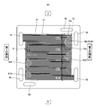
- FIG. 1 is a schematic diagram showing a schematic configuration of a fuel cell according to Embodiment 1 of the present invention.
- FIG. 2 is a schematic diagram showing a schematic configuration of a fuel cell separator in the fuel cell shown in FIG.
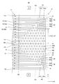
- FIG. 3 is an enlarged schematic view of the vicinity of the folded portion of the fuel gas flow region in the fuel cell separator shown in FIG.
- FIG. 4 is a cross-sectional view schematically showing a schematic configuration of the fuel cell stack in the fuel cell system shown in FIGS. 1 and 2.
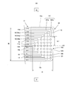
- FIG. 5 is an enlarged schematic view of the vicinity of the folded portion of the fuel gas flow region in the fuel cell separator according to Embodiment 3 of the present invention.
- FIG. 1 is a schematic diagram showing a schematic configuration of a fuel cell according to Embodiment 1 of the present invention.
- FIG. 2 is a schematic diagram showing a schematic configuration of a fuel cell separator in the fuel cell shown in FIG.
- FIG. 3 is an enlarged schematic view of the vicinity of the folded portion
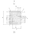
- FIG. 6 is an enlarged schematic view of the vicinity of the folded portion of the fuel gas flow region in the fuel cell separator according to Embodiment 4 of the present invention.
- FIG. 7 is an enlarged schematic view of the vicinity of the folded portion of the fuel gas flow region in the fuel cell separator according to Embodiment 4 of the present invention.
- FIG. 8 is a front view schematically showing a schematic configuration of the solid polymer electrolyte fuel cell separator disclosed in Patent Document 1. As shown in FIG.
- FIG. 1 is a schematic diagram showing a schematic configuration of a fuel cell according to Embodiment 1 of the present invention.
- a fuel cell 100 includes, for example, a cell stack 102, end plates 111A and 111B disposed at both ends of the cell stack 102, and a cell stack. And a fastener (not shown) for fastening the plate 102 and the end plates 111A and 111B in the stacking direction of the cells 101.
- An insulating plate 112A and a current collector plate 113A are disposed between the end plate 111A and the cell stack 102.
- an insulating plate 112B and a current collector plate 113B are disposed between the end plate 111B and the cell stack 102.
- the cell stack 102 includes a plurality of cells 101, and the plurality of cells 101 are stacked in the thickness direction.
- the cell stack 102 is provided with a fuel gas supply manifold, an oxidant gas supply manifold, a cooling medium supply manifold, a fuel gas discharge manifold, an oxidant gas discharge manifold, and a cooling medium discharge manifold (all not shown). ).
- the end plate 111A, the insulating plate 112A, and the current collector plate 113A are provided with through holes corresponding to (communicating with) each manifold such as a fuel gas supply manifold.
- each manifold such as the fuel gas supply manifold of the end plate 111A
- a pipe for supplying or discharging the fuel gas a pipe for supplying or discharging the oxidant gas
- a pipe for supplying or discharging the cooling medium are connected (both not shown).
- fuel gas or the like is supplied to the fuel cell 100, and fuel gas or the like that is not used is discharged from the fuel cell 100.
- a cell 101 includes an MEA (Membrane-Electrode-Assembly: membrane-electrode assembly) 5 and a pair of fuel cell separators according to Embodiment 1 of the present invention (hereinafter simply referred to as separators). 6A, 6B and a pair of gaskets 7A, 7B.
- MEA Membrane-Electrode-Assembly: membrane-electrode assembly
- the MEA 5 includes a pair of electrodes 4A and 4B and an electrolyte layer 1 disposed between the pair of electrodes 4A and 4B.
- the electrode 4A constitutes the anode 4A
- the electrode 4B constitutes the cathode 4B.
- the electrolyte layer 1 for example, a polymer electrolyte membrane that selectively transports hydrogen ions (for example, Nafion (trade name) manufactured by DuPont, USA) can be used.
- the electrolyte layer 1 has a substantially quadrangular (here, rectangular) shape in the first embodiment.
- An anode 4A and a cathode 4B are respectively disposed on both surfaces of the electrolyte layer 1 so as to be located inward from the peripheral edge.
- a fuel gas supply manifold hole, a cooling medium supply manifold hole, an oxidant gas supply manifold hole, a fuel gas discharge manifold hole, a cooling medium discharge manifold hole, and an oxidant gas discharge manifold hole are provided at the periphery of the electrolyte layer 1. It is provided so as to penetrate in the thickness direction (not shown).
- the anode 4A is provided on one main surface of the electrolyte layer 1, and is a mixture of conductive carbon particles carrying an electrode catalyst (for example, platinum and an alloy containing platinum) and a polymer electrolyte having hydrogen ion conductivity. And an anode gas diffusion layer 3A that is provided on the main surface of the anode catalyst layer 2A and has both gas permeability and conductivity.
- the cathode 4B is provided on the other main surface of the electrolyte layer 1, and includes conductive carbon particles carrying an electrode catalyst (for example, platinum and an alloy containing platinum), and a polymer electrolyte having hydrogen ion conductivity.
- a cathode gas diffusion layer 3B provided on the main surface of the cathode catalyst layer 2B and having both gas permeability and conductivity.
- the anode catalyst layer 2A and the cathode catalyst layer 2B use a catalyst layer forming ink containing conductive carbon particles carrying an electrode catalyst made of platinum and an alloy containing platinum, a polymer electrolyte, and a dispersion medium. And can be formed by methods known in the art.
- the material constituting the anode gas diffusion layer 3A and the cathode gas diffusion layer 3B is not particularly limited, and materials known in the art can be used.
- conductive materials such as carbon cloth and carbon paper can be used.
- a porous porous substrate can be used.
- the conductive porous substrate may be subjected to water repellent treatment by a conventionally known method.
- annular gaskets 7A and 7B are sandwiched around the electrolyte layer 1 around the anode 4A and the cathode 4B of the MEA 5 (more precisely, outside the anode gas diffusion layer 3A (cathode gas diffusion layer 3B)). It is arranged. Thereby, it is suppressed that fuel gas and oxidant gas leak out of the cell 101, and these gases are suppressed from being mixed with each other in the cell 101.
- manifold holes (not shown) such as fuel gas supply manifold holes each having a through hole in the thickness direction are provided at the peripheral edge portions of the gaskets 7A and 7B.
- a pair of conductive plate-like separators 6A and 6B are arranged so as to sandwich the MEA 5 and the gaskets 7A and 7B.
- MEA 5 is mechanically fixed, and when a plurality of cells 101 are stacked in the thickness direction, MEA 5 is electrically connected.
- these separators 6A and 6B can use the metal excellent in heat conductivity and electroconductivity, graphite, or what mixed graphite and resin, for example, carbon powder and a binder (solvent).
- a mixture prepared by injection molding or a plate of titanium or stainless steel plated with gold can be used.
- a fuel gas flow region 8 through which fuel gas flows is provided on one main surface that contacts the anode 4A of the separator 6A, and a cooling medium flows on the other main surface.
- a groove-like cooling medium flow area 10 is provided.
- an oxidant gas flow region 9 through which an oxidant gas flows is provided on one main surface that contacts the cathode 4B of the separator 6B, and a cooling surface is provided on the other main surface.
- a groove-shaped cooling medium flow region 10 for flowing the medium is provided.
- each manifold hole such as a fuel gas supply manifold hole is provided in the peripheral portion of the main surface of the separators 6A and 6B (not shown).
- reaction gases fuel gas and oxidant gas (these are called reaction gases) are supplied to the anode 4A and the cathode 4B, respectively, and these reaction gases react to generate electricity and heat, and water is Generated. Further, the generated heat is recovered by flowing a cooling medium such as cooling water through the cooling medium flow area 10.
- the fuel cell 100 is configured such that a plurality of cells 101 are stacked and fastened by the end plates 111A, 111B, and the like.
- the present invention is not limited to this. You may comprise so that it may fasten by 111A and 111B.
- FIG. 2 is a schematic diagram showing a schematic configuration of the separator 6A in the fuel cell 100 shown in FIG.
- the up-down direction in a separator is represented as the up-down direction in a figure.
- the separator 6A has a plate shape and is substantially rectangular.
- a plurality of through holes are formed in the peripheral portion of the main surface of the separator 6A, and these through holes constitute manifold holes such as the fuel gas supply manifold hole 91 and the like.
- a fuel gas supply manifold hole 91 is provided in an upper part of one side part (hereinafter referred to as a first side part) of the separator 6A, and an oxidant gas discharge manifold hole is provided in the lower part thereof. 94 is provided.
- a cooling medium discharge manifold hole 96 is provided inside the oxidant gas discharge manifold hole 94.
- an oxidant gas supply manifold hole 93 is provided in the upper part of the other side part (hereinafter referred to as the second side part) of the separator 6A, and a fuel gas discharge manifold hole 92 is provided in the lower part. It has been.
- a cooling medium supply manifold hole 95 is provided inside the oxidant gas supply manifold hole 93.
- a bent fuel gas flow region 8 is provided on one main surface of the separator 6A so as to connect the fuel gas supply manifold hole 91 and the fuel gas discharge manifold hole 92.
- the fuel gas flow region 8 is formed in a band shape (more specifically, a serpentine shape) as a whole when viewed from the thickness direction of the separator 6A.
- the fuel gas flow region 8 has a plurality of groove-like straight portions 11 and one or more folded portions 12, and the folded portions 12 are connected to the straight portions 11 a (hereinafter referred to as upstream portions) from the folded portions 12.
- the upstream straight portion (see FIG. 3)) and the straight portion 11b on the downstream side of the folded portion 12 (hereinafter, the downstream straight portion (see FIG. 3)). It is formed so as to be folded back from the upstream linear portion 11a to the downstream linear portion 11b.
- the straight portion 11 is formed by a flow channel and is configured so that fuel gas flows (divides).
- at least one (four in the first embodiment) of the one or more folded portions 12 has a gas merging portion 12a, a gas mixing portion 12b, and a gas diverting portion 12c.
- channel which comprises the several linear part 11 forms the 1st rib part 13 contact
- the portion between the flow channel grooves that constitute the plurality of linear portions 11 is defined as the first rib portion 13 that contacts the anode 4A.
- the some linear part 11 is formed in one main surface of the separator 6A so that the some (2 or more) 1st rib part 13 may be formed.
- the plurality of straight line portions 11 are configured such that the number of upstream straight line portions 11a is larger than the number of downstream straight line portions 11b. You may comprise so that the number of the linear parts 11a and the number of the downstream linear parts 11b may become the same.
- the fuel gas flow region 8 includes at least one of the plurality of flow dividing regions 81A, 81C, 81E, 81G, 81I including at least the straight portion 11 among the plurality of straight portions 11 and the one or more folded portions 12.
- the merge area 81B corresponds to the gas mixing section 12b of the folded section 12.
- FIG. 3 is an enlarged schematic view of the vicinity of the folded portion 12 of the fuel gas flow region 8 in the separator 6A shown in FIG.
- the extending direction of the first rib portion 13 is represented as the X-axis direction
- the direction perpendicular to the extending direction of the first rib portion 13 is represented as the Y-axis direction. That is, the direction perpendicular to the extending direction of the first rib portion 13 is the vertical direction in FIG. 3 and not the thickness direction of the separator 6A.
- the up-down direction in the separator 6A is represented as the up-down direction in the figure.
- the folded portion 12 of the fuel gas flow region 8 is formed in a substantially rectangular shape when viewed from the thickness direction of the separator 6A, and is provided with a U-shaped outer peripheral wall.
- One end of the U-shaped outer peripheral wall is flush with the wall of the upstream straight portion 11a located on the uppermost side, and the other end of the U-shaped outer peripheral wall is the lowermost straight line located on the lowermost side. It is flush with the wall of the portion 11b.
- the wall extending in the vertical direction (Y-axis direction) of the outer peripheral wall is referred to as the outer end 12A.
- the first rib portion 13 formed between the upstream straight portion 11a and the downstream straight portion 11b adjacent to each other is a central rib portion 13A, passing through the center in the width direction of the central rib portion 13A, and
- An imaginary line extending in the extending direction of the central rib portion 13A is defined as a center line 131, passing through the tip of the central rib portion 13A and extending in a direction perpendicular to the center line 131 (that is, the vertical direction: Y-axis direction).
- the line is defined as the boundary line 132
- the boundary between the folded portion 12 and the straight line portion 11 is the boundary line 132 in the first embodiment.
- the tip of the first rib portion 13 is an intersection line with the boundary line 132 in the first rib portion 13.
- the folded portion 12 includes the gas merging portion 12a indicated by the broken line in FIG. 3, the gas diversion portion 12c indicated by the alternate long and short dash line, and the gas other than the gas merging portion 12a and the gas diversion portion 12c. And a mixing unit 12b.
- the gas merging portion 12 a and the gas diverting portion 12 c are connected to the first rib portion 13 at the base end, and are provided with a second rib portion 14 extending from the first rib portion 13.
- the second rib portions 14 have the second rib portion 14 located closer to the central rib portion 13A than the central rib portion 13A. It is formed so that the length in the extending direction is shorter than the second rib portion 14 located on the far side.
- the second rib portion 14 located on the side closer to the central rib portion 13A is the one having the shorter vertical distance from the central rib portion 13A.
- the second rib portion 14 is a second rib portion 14 located on the far side of the central rib portion 13A among the two second rib portions 14 adjacent to each other, and the distance in the vertical direction with respect to the central rib portion 13A is The longer second rib portion 14 is referred to.
- the second rib portion 14 positioned on the side closer to the central rib portion 13A is referred to as the second rib portion 14 positioned on the inner side and adjacent to each other.
- the second rib portion 14 located on the far side from the central rib portion 13 ⁇ / b> A may be referred to as the second rib portion 14 located on the outer side.
- the length in the stretching direction refers to the length of the first rib portion 13 in the stretching direction, that is, the length in the X-axis direction (horizontal direction) shown in FIG.
- the length in the extending direction refers to the length from the base end portion of the second rib portion 14 to the end portion that extends most in the X-axis direction. Therefore, as illustrated in FIG. 3, the second rib portion 14 has a shorter length in the X-axis direction in the second rib portion 14 b located on the inner side than in the second rib portion 14 a located on the outer side. It is formed to become.
- the inner second rib portion 14 b and the outer second rib portion 14 a are examples, and for example, the second rib portion 14 a and the second rib portion 14 c positioned above the second rib portion 14 c are contrasted.
- the second rib portion 14c located above the second rib portion 14a is located on the outer side than the second rib portion 14a, the second rib portion 14a becomes the second rib portion located on the inner side.
- the portion 14c is a second rib portion located outside.
- all the second rib portions 14 are folded back with the end closest to the outer end 12A of each folded portion 12 as the distance from the central rib portion 13A increases in the arrangement in the linear portion 11 (in the arrangement in the vertical direction).
- the distance from the outer end 12A of the part 12 is formed to be long.
- the 2nd rib part 14 provided in at least one (both in this Embodiment 1) of the gas confluence
- a second rib portion 141 (hereinafter referred to as an outermost second rib portion) 141 is formed so as to be bent inward toward the center line 131.
- the outermost second rib portion 141 includes a longitudinal portion 141a formed so as to extend from the first rib portion 13 in the extending direction of the first rib portion 13, and a tip end of the longitudinal portion 141a.
- the outermost second rib portion 141 is formed in an L shape when viewed from the thickness direction of the separator 6A.
- At least one of the gas confluence portion 12a and the gas diversion portion 12c (both in the first embodiment) provided with the outermost second rib portion 141 is a plurality of second rib portions 14 adjacent to each other. Is bent inward toward the center line 131.
- the plurality of second rib portions 14 formed to be bent include the outermost second rib portion 141. Therefore, in the first embodiment, the second rib portion 14 formed to be bent includes the outermost second rib portion 141 and the second rib adjacent to the outermost second rib portion 141.
- a portion 142 hereinafter referred to as a bent second rib portion 142
- a second rib portion 143 hereinafter referred to as a bent second rib portion 143 adjacent to the bent second rib portion 142.
- the bent second rib portion 142 includes a longitudinal portion 142a formed so as to extend from the first rib portion 13 in the extending direction of the first rib portion 13, and an inner side from the tip of the longitudinal portion 142a toward the center line 131.
- a short portion 142b extending in the direction, and the short portion 142b is formed to extend along the outer end 12A of the folded portion 12 (along the Y-axis direction).
- the bent second rib portion 142 is formed in an L shape when viewed from the thickness direction of the separator 6A. Since the bent second rib portion 143 is configured in the same manner as the bent second rib portion 142, detailed description thereof is omitted.
- the outermost second rib portion 141 and the bent second rib portions 142 and 143 are the second ribs in which the distance between the tip portion of the second rib portion 14 located on the inner side and the center line 131 is located on the outer side. It is formed so as to be less than or equal to the distance between the tip of the portion 14 and the center line 131.
- the outermost second rib portion 141 and the bent second rib portion 142 are arranged such that the distal end portion and the center line 131 of the bent second rib portion 142 located inside the outermost second rib portion 141. Is formed to be equal to or longer than the distance L1 between the tip of the outermost second rib portion 141 and the center line 131 (the same distance in the first embodiment).
- the bent second rib portion 142 and the bent second rib portion 143 are such that the distance L3 between the distal end portion of the bent second rib portion 143 and the center line 131 is the same as the distal end portion of the bent second rib portion 142 and the center line 131.
- Distance L2 or more the same distance in the first embodiment.
- the plurality of second rib portions 14 formed so as to be bent are centered on the distal end portion of the second rib portion 14 located outside the distal end portion of the second rib portion 14 located on the inner side.
- the gas mixing part 12 b has a recess 121 and a plurality of protrusions 122.
- the recess 121 is formed so as to communicate with a groove formed between the second rib portions 14.
- the protrusion 122 is provided so as to extend in the thickness direction of the separator 6 ⁇ / b> A from the bottom surface of the recess 121, and is formed in a columnar shape (precisely, a true columnar shape).
- the protrusions 122 are disposed so as to overlap each other when viewed from the extending direction of the first rib portion 13 (X-axis direction: horizontal direction).
- the protrusion 122 is an extension of the second rib portion 14 (here, the second rib portion 14 that is not bent) as viewed from the extending direction of the first rib portion 13 (X-axis direction: horizontal direction). It is provided above.
- the protrusions 122 are arranged in a staggered manner when viewed from the direction perpendicular to the extending direction of the first rib portion 13 (Y-axis direction: up-down direction).
- the protrusions 122 are arranged in a staggered manner so that the protrusions 122 adjacent to each other in the Y-axis direction do not overlap each other or part of them overlap when viewed from the Y-axis direction. It is said that it is arranged.
- the protrusion 122 (outer protrusion 122A) is provided on extension of the groove
- the protrusion 122 (outer protrusion 122A) is provided. More specifically, the outer flow path 15 is extended so that a part of the outer protrusion 122A is located when viewed from the extending direction (Y-axis direction: vertical direction) of the short part 141b of the outermost second rib part 141. It is arranged on the top.
- the fuel gas that has flowed through the upstream linear portion 11a flows through the gas merging portion 12a of the turning portion 12 and is supplied to the gas mixing portion 12b.
- the flow of the fuel gas supplied to the gas mixing unit 12b is disturbed by the plurality of projections 122, and gas mixing is promoted.
- the mixed fuel gas is diverted to the gas diverter 12c.
- the fuel gas diverted to the gas diversion part 12c flows through the downstream straight part 11b.
- the protrusion part 122 is formed in the substantially cylindrical shape, it is not limited to this, A cylindrical shape, a triangular prism shape, and a quadrangular prism shape may be sufficient.
- the protrusion 122 has a round cross section perpendicular to the thickness direction of the separator 6 ⁇ / b> A, but is not limited thereto, and may be an ellipse.
- the outermost second rib portion 141 in the gas merge portion 12a of the folded portion 12 is formed to be bent inward toward the center line 131. ing. Accordingly, a groove (outer flow path 15) formed between the outer peripheral wall of the folded portion 12 and the outermost second rib portion 141 of the gas confluence portion 12a is formed to extend downward. Therefore, the fuel gas that has flowed through the outer flow path 15 of the gas merging portion 12a is likely to flow downward, that is, along the outer end of the folded portion 12. Therefore, retention of fuel gas and condensed water (product water) can be suppressed. Further, the contact area between the separator 6A and the anode 4A can be increased, and the electrical contact resistance between the separator 6A and the anode 4A can be reduced.
- the outermost second rib portion 141 in the gas flow dividing portion 12c of the folded portion 12 is formed to be bent inward toward the center line 131.
- turning part 12 and the outermost 2nd rib part 141 of the gas distribution part 12c is formed so that it may extend upwards. Therefore, the fuel gas that has flowed from the gas merging portion 12a through the gas mixing portion 12b is easily supplied to the outer flow path 15 of the gas diverting portion 12c, and the retention of fuel gas and condensed water (product water) is suppressed. it can. Further, the contact area between the separator 6A and the anode 4A can be increased, and the electrical contact resistance between the separator 6A and the anode 4A can be reduced.
- the folded portion is formed from the outer flow path 15 of the gas merging portion 12a. 12
- the fuel gas is more easily supplied to the outer flow path 15 of the gas diverting portion 12c through the vicinity of the outer end 12A, and the retention of the fuel gas and the condensed water (product water) can be further suppressed.
- the contact area with the anode 4A can be increased, and the electrical contact resistance between the separator 6A and the anode 4A can be further reduced.
- the outermost second rib portion 141 and the bent second rib portions 142 and 143 in the gas confluence portion 12a are bent inward toward the center line 131, and The distance between the tip of the second rib portion 14 located on the inner side and the center line 131 is equal to or less than the distance between the tip of the second rib portion 14 located on the outer side and the center line 131. .
- a groove (flow path) formed between the outermost second rib portion 141 and the bent second rib portion 142 and between the bent second rib portion 142 and the bent second rib portion 143 are formed.
- the groove (flow path) is formed to extend downward.
- a groove (flow path) formed between the outermost second rib portion 141 and the bent second rib portion 142 and a bent second rib portion 142 and the bent second rib portion 143 are formed.
- the fuel gas that has flowed through the groove (flow path) is likely to flow downward. Therefore, the stay of fuel gas and condensed water (product water) can be further suppressed.
- the contact area between the separator 6A and the anode 4A can be increased, and the electrical contact resistance between the separator 6A and the anode 4A can be further reduced.
- the outermost second rib portion 141 and the bent second rib portions 142 and 143 in the gas distribution portion 12c are bent inward toward the center line 131, and The distance between the tip of the second rib portion 14 located on the inner side and the center line 131 is equal to or less than the distance between the tip of the second rib portion 14 located on the outer side and the center line 131. .
- a groove (flow path) formed between the outermost second rib portion 141 and the bent second rib portion 142 and between the bent second rib portion 142 and the bent second rib portion 143 are formed.
- the groove (flow path) is formed to extend upward.
- a groove (flow path) and a bent second rib portion formed between the outermost second rib portion 141 and the bent second rib portion 142 through the gas mixing portion 12b from the gas junction portion 12a The fuel gas is more easily supplied to the groove (flow path) formed between 142 and the bent second rib portion 143, and the retention of the fuel gas and the condensed water (product water) can be further suppressed.
- the contact area between the separator 6A and the anode 4A can be increased, and the electrical contact resistance between the separator 6A and the anode 4A can be further reduced.
- the outermost second rib portion 141 and the bent second rib portions 142 and 143 are provided in both the gas merging portion 12a and the gas diverting portion 12c, the gas merging Formed between the outermost second rib portion 141 and the bent second rib portion 142 of the portion 12a and between the bent second rib portion 142 and the bent second rib portion 143.
- tip part of the 2nd rib part 14 located inside and the centerline 131 is the front-end
- the protrusions 122 overlap each other on the extension of the second rib portion 14 when viewed from the extending direction (X-axis direction) of the first rib portion 13. It is arranged like this. That is, the protrusion 122 is not disposed on an extension of a groove (flow path) formed between the adjacent second rib portions 14 in the X-axis direction. For this reason, the movement to the X-axis direction of the fuel gas which flowed through the groove
- the protrusion part 122 is arrange
- the protrusion 122 (outer protrusion 122A) is also disposed on the extension of the outer flow path 15. For this reason, mixing of the fuel gas flowing through the vicinity of the outer end 12A of the folded portion 12 can be promoted.
- FIG. 4 is an enlarged schematic view of the vicinity of the folded portion of the fuel gas flow region in the fuel cell separator according to Embodiment 2 of the present invention. Since the oxidant gas flow region has the same configuration as the fuel gas flow region, detailed description thereof is omitted.
- the fuel cell separator 6A according to the second embodiment of the present invention has the same basic configuration as the fuel cell separator 6A according to the first embodiment, but only in the gas junction 12a.
- the difference is that the outermost second rib portion 141 is provided and only one second rib portion 14 (that is, the outermost second rib portion 141) is formed to be bent.
- the protrusions 122 in the gas mixing portion 12b are mutually viewed from the direction perpendicular to the extending direction of the first rib portion 13 (Y-axis direction: vertical direction). It arrange
- the area of the gas mixing portion 12b is S, and the leading end of the second rib portion 14 connected to the central rib portion 13A to the outer end of the folded portion 12 is used.
- the gas mixing unit 12b is formed so that the area S of the gas mixing unit 12b satisfies the formula (1) when the distance is A and the length in the direction perpendicular to the center line 131 of the folded portion 12 is B. ing.
- the fuel gas flowing through the outer flow path 15 of the gas merging portion 12a is directed downward, that is, It becomes easy to flow along the outer end of the folded portion 12. Therefore, retention of fuel gas and condensed water (product water) can be suppressed. Further, the contact area with the anode 4A can be increased, and the electrical contact resistance between the separator 6A and the anode 4A can be reduced.
- FIG. 5 is an enlarged schematic view of the vicinity of the folded portion of the fuel gas flow region in the fuel cell separator according to Embodiment 3 of the present invention. Since the oxidant gas flow region has the same configuration as the fuel gas flow region, detailed description thereof is omitted.
- the fuel cell separator 6A according to Embodiment 3 of the present invention has the same basic configuration as the fuel cell separator 6A according to Embodiment 2, but the outermost second rib. The difference is that the portion 141 is provided not in the gas confluence portion 12a but in the gas diversion portion 12c.
- the fuel gas that has flowed from the gas merging portion 12a through the gas mixing portion 12b is outside the gas diverting portion 12c. It becomes easy to be supplied to the flow path 15, and the retention of fuel gas and condensed water (product water) can be suppressed. Further, the contact area with the anode 4A can be increased, and the electrical contact resistance between the separator 6A and the anode 4A can be reduced.
- FIG. 6 is an enlarged schematic view of the vicinity of the folded portion of the fuel gas flow region in the fuel cell separator according to Embodiment 4 of the present invention. Since the oxidant gas flow region has the same configuration as the fuel gas flow region, detailed description thereof is omitted.
- the fuel cell separator 6A according to Embodiment 4 of the present invention has the same basic configuration as the fuel cell separator 6A according to Embodiment 1, but only in the gas junction 12a. The difference is that the outermost second rib portion 141 and the bent second rib portions 142 and 143 are provided.
- the outermost second rib portion 141 and the bent second rib portion 142 have a distance L2 between the distal end portion of the bent second rib portion 142 and the center line 131. Is formed to be smaller than the distance L1 between the tip end portion of the outermost second rib portion 141 and the center line 131. Further, the bent second rib portion 142 and the bent second rib portion 143 are such that the distance L3 between the distal end portion of the bent second rib portion 143 and the center line 131 is the same as the distal end portion of the bent second rib portion 142 and the center line 131. It is formed to be smaller than the distance L2.
- the outer flow path 15, the outermost second rib portion 141, and the bent second rib of the gas merging portion 12a The fuel gas flowing through the groove (flow path) formed between the bent portion 142 and the groove (flow path) formed between the bent second rib portion 142 and the bent second rib portion 143 flows downward. It becomes easy to flow toward, that is, along the outer end of the folded portion 12. Therefore, retention of fuel gas and condensed water (product water) can be suppressed.
- the fuel gas flowing through the outer flow path 15 is not restrained from moving inward of the gas mixing part 12b by the bent second rib parts 142 and 143. That is, the second rib portion 14 located on the inner side does not prevent the fuel gas from moving inward of the gas mixing portion 12b. For this reason, mixing of fuel gas is less likely to be suppressed in the gas mixing unit 12b.
- the contact area between the separator 6A and the anode 4A can be increased, and the electrical contact resistance between the separator 6A and the anode 4A can be reduced.
- the outermost second rib portion 141, the bent second rib portion 142, and the bent second rib portion 143 have a distance L2 smaller than the distance L1 and a distance L3 smaller than the distance L2.
- the outermost second rib portion 141, the bent second rib portion 142, and the bent second rib portion 143 are formed such that the distance L2 and the distance L1 are the same length, and the distance L3 is smaller than the distance L2, for example.
- the distance L2 may be smaller than the distance L1, and the distance L3 and the distance L2 may be the same length.
- FIG. 7 is an enlarged schematic view of the vicinity of the folded portion of the fuel gas flow region in the fuel cell separator according to Embodiment 4 of the present invention. Since the oxidant gas flow region has the same configuration as the fuel gas flow region, detailed description thereof is omitted.
- the fuel cell separator 6A according to the fifth embodiment of the present invention has the same basic configuration as the fuel cell separator 6A according to the second embodiment.
- a point in which the ribs 13 are arranged in a staggered manner as viewed from the direction perpendicular to the extending direction of the rib portion 13 (Y-axis direction) and an outer protrusion 122A are formed by a part of the outer end 12A of the folded portion 12. Is different.
- a convex portion 122A is formed so that a part of the wall constituting the outer end 12A of the folded portion 12 protrudes inward (X-axis direction), and the convex portion 122A is formed as the outer protruding portion 122A.
- the outer protrusion 122 ⁇ / b> A is provided so as to contact the outer end 12 ⁇ / b> A of the folded portion 12.
- the mixing of the fuel gas flowing near the outer end 12A of the folded portion 12 can be promoted.
- the outer end 12A of the folded portion 12 in the fuel cell separator 6A according to the first to fourth embodiments is a convex portion like the outer end 12A of the folded portion 12 in the fuel cell separator 6A according to the fifth embodiment. It is good also as a structure which provides 122A.
- the fuel cell separator and the fuel cell including the same according to the present invention can further suppress the retention of the reaction gas at the folded portion, and can further reduce the electrical contact resistance between the separator and the electrode. It is useful in the technical field of fuel cells.
- Electrolyte layer (polymer electrolyte membrane) 2A Anode catalyst layer 2B Cathode catalyst layer 3A Anode gas diffusion layer 3B Cathode gas diffusion layer 4A Anode (electrode) 4B cathode (electrode) 5 MEA (Membrane-Electrode-Assembly) 6A separator 6B separator 7A gasket 7B gasket 8 fuel gas flow region 9 oxidant gas flow region 10 cooling medium flow region 6A fuel cell separator 7A gasket 7B gasket 8 fuel gas flow region 9 oxidant gas flow region 10 Cooling medium flow area 10 Cooling medium flow path 11 Straight portion 11a Upstream straight portion 11b Downstream straight portion 12 Folding portion 12a Gas confluence portion 12b Gas mixing portion 12c Gas diversion portion 12A Outer end 13 First rib portion 13A Central rib portion 14 2nd rib part 14b 2nd rib part 14a 2nd rib part 14c 2nd rib part 15 Outer channel 91 Fuel gas supply manifold hole
Abstract
Description
[燃料電池の構成]
図1は、本発明の実施の形態1に係る燃料電池の概略構成を示す模式図である。 (Embodiment 1)
[Configuration of fuel cell]
FIG. 1 is a schematic diagram showing a schematic configuration of a fuel cell according to
次に、図1及び図2を参照しながら、本発明の実施の形態1に係る燃料電池用セパレータ(ここでは、セパレータ6A)の構成についてさらに詳細に説明する。なお、セパレータ6Bについては、セパレータ6Aと基本的構成が同じであるため、その詳細な説明は省略する。 [Configuration of fuel cell separator]
Next, the configuration of the fuel cell separator (here, the
次に、実施の形態1に係るセパレータ6A及びそれを備える燃料電池100の作用効果を図1乃至図3を参照しながら説明する。なお、酸化剤ガスが通流するセパレータ6Bの作用効果についても、燃料ガスが通流するセパレータ6Aの作用効果と同じであるため、その詳細な説明は省略する。 [Operation effect of fuel cell separator and fuel cell including the same]
Next, functions and effects of the
図4は、本発明の実施の形態2に係る燃料電池用セパレータにおける燃料ガス通流領域の折り返し部近傍を拡大した模式図である。なお、酸化剤ガス通流領域は、燃料ガス通流領域と同様の構成であるため、その詳細な説明は省略する。 (Embodiment 2)
FIG. 4 is an enlarged schematic view of the vicinity of the folded portion of the fuel gas flow region in the fuel cell separator according to Embodiment 2 of the present invention. Since the oxidant gas flow region has the same configuration as the fuel gas flow region, detailed description thereof is omitted.
これにより、セパレータ6Aとアノード4Aとの接触面積を大きくすることができ、セパレータ6Aとアノード4Aとの間の電気的な接触抵抗をより低減することができる。 S <A × B ÷ 2 (1)
Thereby, the contact area between the
図5は、本発明の実施の形態3に係る燃料電池用セパレータにおける燃料ガス通流領域の折り返し部近傍を拡大した模式図である。なお、酸化剤ガス通流領域は、燃料ガス通流領域と同様の構成であるため、その詳細な説明は省略する。 (Embodiment 3)
FIG. 5 is an enlarged schematic view of the vicinity of the folded portion of the fuel gas flow region in the fuel cell separator according to Embodiment 3 of the present invention. Since the oxidant gas flow region has the same configuration as the fuel gas flow region, detailed description thereof is omitted.
図6は、本発明の実施の形態4に係る燃料電池用セパレータにおける燃料ガス通流領域の折り返し部近傍を拡大した模式図である。なお、酸化剤ガス通流領域は、燃料ガス通流領域と同様の構成であるため、その詳細な説明は省略する。 (Embodiment 4)
FIG. 6 is an enlarged schematic view of the vicinity of the folded portion of the fuel gas flow region in the fuel cell separator according to Embodiment 4 of the present invention. Since the oxidant gas flow region has the same configuration as the fuel gas flow region, detailed description thereof is omitted.
図7は、本発明の実施の形態4に係る燃料電池用セパレータにおける燃料ガス通流領域の折り返し部近傍を拡大した模式図である。なお、酸化剤ガス通流領域は、燃料ガス通流領域と同様の構成であるため、その詳細な説明は省略する。 (Embodiment 5)
FIG. 7 is an enlarged schematic view of the vicinity of the folded portion of the fuel gas flow region in the fuel cell separator according to Embodiment 4 of the present invention. Since the oxidant gas flow region has the same configuration as the fuel gas flow region, detailed description thereof is omitted.
2A アノード触媒層
2B カソード触媒層
3A アノードガス拡散層
3B カソードガス拡散層
4A アノード(電極)
4B カソード(電極)
5 MEA(Membrane-Electrode-Assembly:膜-電極接合体)
6A セパレータ
6B セパレータ
7A ガスケット
7B ガスケット
8 燃料ガス通流領域
9 酸化剤ガス通流領域
10 冷却媒体通流領域
6A 燃料電池用セパレータ
7A ガスケット
7B ガスケット
8 燃料ガス通流領域
9 酸化剤ガス通流領域
10 冷却媒体通流領域
10 冷却媒体流路
11 直線部
11a 上流側直線部
11b 下流側直線部
12 折り返し部
12a ガス合流部
12b ガス混合部
12c ガス分流部
12A 外端
13 第1リブ部
13A 中央リブ部
14 第2リブ部
14b 第2リブ部
14a 第2リブ部
14c 第2リブ部
15 外側流路
91 燃料ガス供給マニホールド孔
92 燃料ガス排出マニホールド孔
93 酸化剤ガス供給マニホールド孔
94 酸化剤ガス排出マニホールド孔
95 冷却媒体供給マニホールド孔
96 冷却媒体排出マニホールド孔
100 燃料電池
101 セル
102 セル積層体
111A 端板
111B 端板
112A 絶縁板
112B 絶縁板
113A 集電板
113B 集電板
121 窪み部
122 突起部
122A 外側突起部(凸部)
131 中心線
132 境界線
141 最外方第2リブ部
141a 長手部
141b 短手部
142 屈曲第2リブ部
142a 長手部
142b 短手部
143 屈曲第2リブ部
307 端
320 通流溝
321 溝部
323 独立通流溝部
323A 独立通流溝部
323a 凸部
324 独立通流溝部
324a 凸部
325 境界凸部
333 境界
350A 部分 1 Electrolyte layer (polymer electrolyte membrane)
2A
4B cathode (electrode)
5 MEA (Membrane-Electrode-Assembly)
Claims (18)
- 板状に形成され、少なくとも一方の主面に、溝状の複数の直線部と1以上の折り返し部とを有し、屈曲状に形成され、反応ガスが通流する反応ガス通流領域が設けられ、
前記複数の直線部の間には第1リブ部が形成され、
前記第1リブ部が複数形成されるように、前記複数の直線部が設けられ、
前記折り返し部は、該折り返し部よりも上流側の前記直線部である、上流側直線部と該折り返し部よりも下流側の前記直線部である、下流側直線部とを接続し、通流する反応ガスが前記上流側直線部から前記下流側直線部へ折り返すように形成され、
前記1以上の折り返し部のうち、少なくとも1の折り返し部は、ガス混合部と該ガス混合部に前記上流側直線部からの前記反応ガスを合流させるガス合流部と該ガス混合部から前記下流直線部に前記反応ガスを分流させるガス分流部と、を有し、
前記ガス混合部は、窪み部と該窪み部の底面から立設された複数の突起部とを有し、
前記ガス合流部及び前記ガス分流部には、前記第1リブ部にその基端が接続され、前記第1リブ部から延伸するように形成された第2リブ部が設けられ、
互いに隣接する前記上流側直線部と前記下流側直線部との間に形成された前記第1リブ部を中央リブ部とし、該中央リブ部の幅方向の中心を通り、かつ、該中央リブ部の延伸方向に延びる仮想線を中心線と定義した場合に、
全ての前記第2リブ部は、互いに隣接する2つの第2リブ部のうち、前記中央リブ部に近い側に位置する前記第2リブ部の方が、前記中央リブ部に遠い側に位置する前記第2リブ部よりも、その延伸方向の長さが短くなるように形成され、
前記ガス合流部及び前記ガス分流部の少なくとも一方に設けられた前記第2リブ部であって、前記中央リブ部から最も遠い側に位置する前記第2リブ部である、最外方第2リブ部が、その厚み方向から見て、前記中心線に向かって内側に屈曲するように形成されている、燃料電池用セパレータ。 It is formed in a plate shape, and has a plurality of groove-like straight line portions and one or more folded portions on at least one main surface, and is formed in a bent shape so that a reaction gas flow region through which a reaction gas flows is provided. And
A first rib portion is formed between the plurality of straight portions,
The plurality of linear portions are provided such that a plurality of the first rib portions are formed,
The folded portion connects the upstream straight portion, which is the straight portion upstream from the folded portion, and the downstream straight portion, which is the straight portion downstream from the folded portion, and flows therethrough. The reaction gas is formed so as to be folded back from the upstream linear portion to the downstream linear portion,
Among the one or more folded portions, at least one folded portion includes a gas mixing portion, a gas merging portion that joins the reaction gas from the upstream linear portion to the gas mixing portion, and the downstream straight line from the gas mixing portion. A gas diverting part for diverting the reaction gas to the part,
The gas mixing part has a hollow part and a plurality of protrusions erected from the bottom surface of the hollow part,
The gas merging portion and the gas diverting portion are provided with a second rib portion formed to extend from the first rib portion with a proximal end connected to the first rib portion,
The first rib portion formed between the upstream linear portion and the downstream linear portion adjacent to each other is a central rib portion, passes through the center of the central rib portion in the width direction, and the central rib portion When the imaginary line extending in the stretching direction is defined as the center line,
All the second rib portions are located on the side farther from the central rib portion than the second rib portion, which is located closer to the central rib portion, of the two adjacent second rib portions. It is formed so that the length in the extending direction is shorter than the second rib portion,
The outermost second rib, which is the second rib portion provided in at least one of the gas merging portion and the gas branching portion, and is the second rib portion located on the side farthest from the central rib portion. The fuel cell separator, wherein the portion is formed so as to bend inward toward the center line when viewed from the thickness direction. - 前記最外方第2リブ部が設けられた前記ガス合流部及び前記ガス分流部の少なくとも一方には、複数の前記第2リブ部が、前記中心線に向かって内方に屈曲するように形成され、
屈曲するように形成された前記複数の第2リブ部である屈曲第2リブ部は、互いに隣接し、かつ、前記中央リブ部に近い側に位置する前記第2リブ部の先端部と前記中心線との間の距離が、前記中央リブ部に遠い側に位置する前記第2リブ部の先端部と前記中心線との間の距離以上となるように形成されている、請求項1に記載の燃料電池用セパレータ。 A plurality of the second rib portions are formed so as to bend inward toward the center line in at least one of the gas confluence portion and the gas diversion portion provided with the outermost second rib portion. And
The bent second rib portions, which are the plurality of second rib portions formed to be bent, are adjacent to each other and located on the side closer to the central rib portion and the center of the second rib portion and the center The distance from a line is formed so that it may become more than the distance between the front-end | tip part of the said 2nd rib part located in the side far from the said center rib part, and the said centerline. Fuel cell separator. - 前記突起部は、前記第1リブ部の延伸方向から見て、互いに重なるように配設されている、請求項1又は2に記載の燃料電池用セパレータ。 3. The fuel cell separator according to claim 1, wherein the protrusions are disposed so as to overlap each other when viewed from the extending direction of the first rib portion.
- 前記突起部は、前記第2リブ部の延長上に配設されている、請求項1~3のいずれかに記載の燃料電池用セパレータ。 4. The fuel cell separator according to claim 1, wherein the protrusion is disposed on an extension of the second rib portion.
- 前記突起部は、前記第1リブ部の延伸方向に対する垂直方向から見て、互いに重なるように配設されている、請求項1~4のいずれかに記載の燃料電池用セパレータ。 5. The fuel cell separator according to claim 1, wherein the protrusions are disposed so as to overlap each other when viewed from a direction perpendicular to the extending direction of the first rib portion.
- 前記突起部は、前記第1リブ部の延伸方向に対する垂直方向から見て、千鳥状に配設されている、請求項1~4のいずれかに記載の燃料電池用セパレータ。 The fuel cell separator according to any one of claims 1 to 4, wherein the protrusions are arranged in a staggered manner when viewed from a direction perpendicular to the extending direction of the first rib portion.
- 前記最外方第2リブ部は、前記第1リブ部から延伸する長手部と該長手部の先端から前記中心線に向かって内方に延伸する短手部とを有し、
前記短手部は前記折り返し部の外端に沿って延びるように形成されている、請求項1~6のいずれかに記載の燃料電池用セパレータ。 The outermost second rib portion has a long portion extending from the first rib portion and a short portion extending inward from the tip of the long portion toward the center line.
The fuel cell separator according to any one of claims 1 to 6, wherein the short portion is formed to extend along an outer end of the folded portion. - 前記最外方第2リブ部は、前記燃料電池用セパレータの厚み方向から見て、L字状に形成されている、請求項7に記載の燃料電池用セパレータ。 The fuel cell separator according to claim 7, wherein the outermost second rib portion is formed in an L shape when viewed from the thickness direction of the fuel cell separator.
- 前記最外方第2リブ部の短手部と前記折り返し部の外端との間に形成される溝の延長上に前記突起部が配設されている、請求項7に記載の燃料電池用セパレータ。 8. The fuel cell according to claim 7, wherein the protrusion is disposed on an extension of a groove formed between a short portion of the outermost second rib portion and an outer end of the folded portion. Separator.
- 前記最外方第2リブ部の短手部と前記折り返し部の外端との間に形成される溝の延長上に配設されている前記突起部は、前記折り返し部の外端の一部で形成されている、請求項9に記載の燃料電池用セパレータ。 The protrusion disposed on the extension of the groove formed between the short side portion of the outermost second rib portion and the outer end of the folded portion is a part of the outer end of the folded portion. The fuel cell separator according to claim 9, which is formed by:
- 前記屈曲第2リブ部は、前記第1リブ部から延伸する長手部と該長手部の先端から前記中心線に向かって内方に延伸する短手部とを有し、
前記短手部は前記折り返し部の外端に沿って延びるように形成されている、請求項2~10のいずれかに記載の燃料電池用セパレータ。 The bent second rib portion has a long portion extending from the first rib portion and a short portion extending inward from the tip of the long portion toward the center line.
11. The fuel cell separator according to claim 2, wherein the short portion is formed to extend along an outer end of the folded portion. - 前記屈曲第2リブ部は、前記燃料電池用セパレータの厚み方向から見て、L字状に形成されている、請求項11に記載の燃料電池用セパレータ。 12. The fuel cell separator according to claim 11, wherein the bent second rib portion is formed in an L shape when viewed from the thickness direction of the fuel cell separator.
- 前記反応ガス通流領域は、前記上流側直線部の数が、前記下流側直線部の数以上になるように設けられている、請求項1~12のいずれかに記載の燃料電池用セパレータ。 The fuel cell separator according to any one of claims 1 to 12, wherein the reaction gas flow region is provided so that the number of the upstream straight portions is equal to or greater than the number of the downstream straight portions.
- 全ての前記第2リブ部は、前記直線部における配列において、前記中央リブ部から遠い程、それぞれの前記折り返し部の外端に最も近い端と前記折り返し部の外端との距離が、長くなるように形成されている、請求項1~13のいずれかに記載の燃料電池用セパレータ。 As for all the second rib portions, the distance between the end closest to the outer end of each folded portion and the outer end of the folded portion increases as the distance from the central rib portion increases in the arrangement in the linear portion. The fuel cell separator according to any one of claims 1 to 13, which is formed as described above.
- 前記反応ガス通領域が、全体として、帯状に形成されている、請求項1~14のいずれかに記載の燃料電池用セパレータ。 The fuel cell separator according to any one of claims 1 to 14, wherein the reaction gas passage region is formed in a band shape as a whole.
- 前記反応ガス通流領域が、全体として、サーペンタイン状に形成されている、請求項15に記載の燃料電池用セパレータ。 The fuel cell separator according to claim 15, wherein the reaction gas flow region is formed in a serpentine shape as a whole.
- 前記ガス混合部の面積をSとし、前記中央リブ部に接続された第2リブ部の先端から前記折り返し部の外端までの距離をAとし、前記折り返し部の前記中心線に対する垂直方向の長さをBとした場合に、
前記ガス混合部は、該ガス混合部の面積SがS<A×B÷2を満たすように形成されている、請求項1~16のいずれかに記載の燃料電池用セパレータ。 The area of the gas mixing part is S, the distance from the tip of the second rib part connected to the central rib part to the outer end of the folded part is A, and the length of the folded part in the direction perpendicular to the center line If B is
The fuel cell separator according to any one of claims 1 to 16, wherein the gas mixing section is formed so that an area S of the gas mixing section satisfies S <A × B / 2. - 請求項1~17のいずれかに記載の燃料電池用セパレータを含む一対の燃料電池用セパレータと、
電解質層と該電解質層を挟む一対の電極を有する電解質層-電極接合体と、を備え、
前記電解質層-電極接合体は、一対の前記燃料電池用セパレータに挟まれている、燃料電池。
A pair of fuel cell separators comprising the fuel cell separator according to any one of claims 1 to 17;
An electrolyte layer and an electrolyte layer-electrode assembly having a pair of electrodes sandwiching the electrolyte layer,
The fuel cell, wherein the electrolyte layer-electrode assembly is sandwiched between a pair of fuel cell separators.
Priority Applications (6)
| Application Number | Priority Date | Filing Date | Title |
|---|---|---|---|
| EP10832817.0A EP2482371B1 (en) | 2009-11-25 | 2010-11-15 | Separator for fuel cell and fuel cell provided with same |
| RU2012126110/07A RU2012126110A (en) | 2009-11-25 | 2010-11-15 | FUEL ELEMENT SEPARATOR AND INCLUDING ITS FUEL ELEMENT |
| CA2778885A CA2778885A1 (en) | 2009-11-25 | 2010-11-15 | Fuel cell separator and fuel cell including same |
| US13/508,926 US20120231373A1 (en) | 2009-11-25 | 2010-11-15 | Fuel cell separator and fuel cell including same |
| JP2011543095A JP5079142B2 (en) | 2009-11-25 | 2010-11-15 | Fuel cell separator and fuel cell comprising the same |
| CN2010800532569A CN102630354A (en) | 2009-11-25 | 2010-11-15 | Separator for fuel cell and fuel cell provided with same |
Applications Claiming Priority (2)
| Application Number | Priority Date | Filing Date | Title |
|---|---|---|---|
| JP2009-268045 | 2009-11-25 | ||
| JP2009268045 | 2009-11-25 |
Publications (1)
| Publication Number | Publication Date |
|---|---|
| WO2011064961A1 true WO2011064961A1 (en) | 2011-06-03 |
Family
ID=44066076
Family Applications (1)
| Application Number | Title | Priority Date | Filing Date |
|---|---|---|---|
| PCT/JP2010/006690 WO2011064961A1 (en) | 2009-11-25 | 2010-11-15 | Separator for fuel cell and fuel cell provided with same |
Country Status (8)
| Country | Link |
|---|---|
| US (1) | US20120231373A1 (en) |
| EP (1) | EP2482371B1 (en) |
| JP (1) | JP5079142B2 (en) |
| KR (1) | KR20120096029A (en) |
| CN (1) | CN102630354A (en) |
| CA (1) | CA2778885A1 (en) |
| RU (1) | RU2012126110A (en) |
| WO (1) | WO2011064961A1 (en) |
Cited By (2)
| Publication number | Priority date | Publication date | Assignee | Title |
|---|---|---|---|---|
| WO2013042283A1 (en) * | 2011-09-21 | 2013-03-28 | パナソニック株式会社 | Polymer electrolyte fuel cell and fuel cell system provided with same |
| JP2013093099A (en) * | 2011-10-24 | 2013-05-16 | Panasonic Corp | Fuel cell separator forming material, fuel cell separator and fuel cell |
Families Citing this family (5)
| Publication number | Priority date | Publication date | Assignee | Title |
|---|---|---|---|---|
| KR102140126B1 (en) | 2016-11-14 | 2020-07-31 | 주식회사 엘지화학 | Separator for fuel cell and fuel cell using the same |
| CN107799787A (en) * | 2017-09-28 | 2018-03-13 | 黑泰(上海)材料科技有限公司 | Fuel battery flow field plates |
| JP7331650B2 (en) * | 2018-11-19 | 2023-08-23 | 株式会社豊田自動織機 | power storage device |
| CN112242536B (en) * | 2019-07-16 | 2022-03-18 | 未势能源科技有限公司 | Bipolar plate structure for fuel cell, fuel cell and fuel cell vehicle |
| CN113594488B (en) * | 2021-07-20 | 2022-09-16 | 嘉寓氢能源科技(辽宁)有限公司 | Air-cooled proton exchange membrane fuel cell metal bipolar plate and fuel cell thereof |
Citations (5)
| Publication number | Priority date | Publication date | Assignee | Title |
|---|---|---|---|---|
| JP2000164230A (en) * | 1998-11-27 | 2000-06-16 | Aisin Seiki Co Ltd | Separator for fuel cell, and fuel cell |
| JP2001052723A (en) * | 1999-08-13 | 2001-02-23 | Honda Motor Co Ltd | Fuel cell stack |
| JP2007207744A (en) * | 2005-08-05 | 2007-08-16 | Matsushita Electric Ind Co Ltd | Separator for fuel cell, and fuel cell |
| JP2007266012A (en) * | 2007-07-13 | 2007-10-11 | Toyota Motor Corp | Separator for fuel cell |
| JP2008010179A (en) * | 2006-06-27 | 2008-01-17 | Toyota Motor Corp | Fuel cell separator |
Family Cites Families (2)
| Publication number | Priority date | Publication date | Assignee | Title |
|---|---|---|---|---|
| US7524575B2 (en) * | 2004-06-07 | 2009-04-28 | Hyteon Inc. | Flow field plate for use in fuel cells |
| WO2007018156A1 (en) * | 2005-08-05 | 2007-02-15 | Matsushita Electric Industrial Co., Ltd. | Separator for fuel cell and fuel cell |
-
2010
- 2010-11-15 KR KR1020127016142A patent/KR20120096029A/en active IP Right Grant
- 2010-11-15 US US13/508,926 patent/US20120231373A1/en not_active Abandoned
- 2010-11-15 RU RU2012126110/07A patent/RU2012126110A/en not_active Application Discontinuation
- 2010-11-15 EP EP10832817.0A patent/EP2482371B1/en active Active
- 2010-11-15 WO PCT/JP2010/006690 patent/WO2011064961A1/en active Application Filing
- 2010-11-15 CA CA2778885A patent/CA2778885A1/en not_active Abandoned
- 2010-11-15 JP JP2011543095A patent/JP5079142B2/en active Active
- 2010-11-15 CN CN2010800532569A patent/CN102630354A/en active Pending
Patent Citations (6)
| Publication number | Priority date | Publication date | Assignee | Title |
|---|---|---|---|---|
| JP2000164230A (en) * | 1998-11-27 | 2000-06-16 | Aisin Seiki Co Ltd | Separator for fuel cell, and fuel cell |
| JP4120072B2 (en) | 1998-11-27 | 2008-07-16 | アイシン精機株式会社 | Separator for solid polymer electrolyte fuel cell and solid polymer electrolyte fuel cell |
| JP2001052723A (en) * | 1999-08-13 | 2001-02-23 | Honda Motor Co Ltd | Fuel cell stack |
| JP2007207744A (en) * | 2005-08-05 | 2007-08-16 | Matsushita Electric Ind Co Ltd | Separator for fuel cell, and fuel cell |
| JP2008010179A (en) * | 2006-06-27 | 2008-01-17 | Toyota Motor Corp | Fuel cell separator |
| JP2007266012A (en) * | 2007-07-13 | 2007-10-11 | Toyota Motor Corp | Separator for fuel cell |
Non-Patent Citations (1)
| Title |
|---|
| See also references of EP2482371A4 * |
Cited By (5)
| Publication number | Priority date | Publication date | Assignee | Title |
|---|---|---|---|---|
| WO2013042283A1 (en) * | 2011-09-21 | 2013-03-28 | パナソニック株式会社 | Polymer electrolyte fuel cell and fuel cell system provided with same |
| CN103119767A (en) * | 2011-09-21 | 2013-05-22 | 松下电器产业株式会社 | Polymer electrolyte fuel cell and fuel cell system provided with same |
| JP5204932B1 (en) * | 2011-09-21 | 2013-06-05 | パナソニック株式会社 | POLYMER ELECTROLYTE FUEL CELL AND FUEL CELL SYSTEM INCLUDING THE SAME |
| US9287574B2 (en) | 2011-09-21 | 2016-03-15 | Panasonic Intellectual Property Management Co., Ltd. | Polymer electrolyte fuel cell and fuel cell system including the same |
| JP2013093099A (en) * | 2011-10-24 | 2013-05-16 | Panasonic Corp | Fuel cell separator forming material, fuel cell separator and fuel cell |
Also Published As
| Publication number | Publication date |
|---|---|
| JPWO2011064961A1 (en) | 2013-04-11 |
| KR20120096029A (en) | 2012-08-29 |
| US20120231373A1 (en) | 2012-09-13 |
| CA2778885A1 (en) | 2011-06-03 |
| CN102630354A (en) | 2012-08-08 |
| EP2482371A1 (en) | 2012-08-01 |
| EP2482371B1 (en) | 2014-03-12 |
| RU2012126110A (en) | 2013-12-27 |
| EP2482371A4 (en) | 2012-09-26 |
| JP5079142B2 (en) | 2012-11-21 |
Similar Documents
| Publication | Publication Date | Title |
|---|---|---|
| JP5079142B2 (en) | Fuel cell separator and fuel cell comprising the same | |
| JP4553976B2 (en) | Fuel cell separator and fuel cell comprising the same | |
| US7569301B2 (en) | Fuel cell | |
| EP2549573B1 (en) | Polymer electrolyte fuel cell and fuel cell stack equipped with same | |
| EP2131430B1 (en) | Polymer electrolyte fuel cell and fuel cell stack having the same | |
| US20040106028A1 (en) | Fuel cell | |
| JP5581206B2 (en) | Fuel cell separator and fuel cell comprising the same | |
| US8119306B2 (en) | Bipolar plate and direct liquid feed fuel cell stack | |
| JP5501237B2 (en) | POLYMER ELECTROLYTE FUEL CELL AND FUEL CELL STACK HAVING THE SAME | |
| JP5581207B2 (en) | Fuel cell separator and fuel cell comprising the same | |
| US7951508B2 (en) | Fuel cell | |
| EP3041075B1 (en) | Fuel cell unit | |
| EP2405515B1 (en) | Fuel cell separator and fuel cell including same | |
| JP6512749B2 (en) | Fuel cell | |
| KR20230129263A (en) | Gas diffusion layer, separator and electrochemical reaction device | |
| JP2011124185A (en) | Polymer electrolyte fuel cell and fuel cell stack with the same |
Legal Events
| Date | Code | Title | Description |
|---|---|---|---|
| WWE | Wipo information: entry into national phase |
Ref document number: 201080053256.9 Country of ref document: CN |
|
| 121 | Ep: the epo has been informed by wipo that ep was designated in this application |
Ref document number: 10832817 Country of ref document: EP Kind code of ref document: A1 |
|
| DPE1 | Request for preliminary examination filed after expiration of 19th month from priority date (pct application filed from 20040101) | ||
| WWE | Wipo information: entry into national phase |
Ref document number: 2778885 Country of ref document: CA |
|
| WWE | Wipo information: entry into national phase |
Ref document number: 2010832817 Country of ref document: EP |
|
| WWE | Wipo information: entry into national phase |
Ref document number: 2011543095 Country of ref document: JP |
|
| WWE | Wipo information: entry into national phase |
Ref document number: 13508926 Country of ref document: US |
|
| NENP | Non-entry into the national phase |
Ref country code: DE |
|
| ENP | Entry into the national phase |
Ref document number: 20127016142 Country of ref document: KR Kind code of ref document: A |
|
| WWE | Wipo information: entry into national phase |
Ref document number: 1559/MUMNP/2012 Country of ref document: IN |
|
| WWE | Wipo information: entry into national phase |
Ref document number: 2012126110 Country of ref document: RU |