WO2011058727A1 - 有機光電変換装置およびこれを用いる有機光電変換方法 - Google Patents
有機光電変換装置およびこれを用いる有機光電変換方法 Download PDFInfo
- Publication number
- WO2011058727A1 WO2011058727A1 PCT/JP2010/006543 JP2010006543W WO2011058727A1 WO 2011058727 A1 WO2011058727 A1 WO 2011058727A1 JP 2010006543 W JP2010006543 W JP 2010006543W WO 2011058727 A1 WO2011058727 A1 WO 2011058727A1
- Authority
- WO
- WIPO (PCT)
- Prior art keywords
- solution
- photoelectric conversion
- oxygen
- organic photoelectric
- conversion device
- Prior art date
- Legal status (The legal status is an assumption and is not a legal conclusion. Google has not performed a legal analysis and makes no representation as to the accuracy of the status listed.)
- Ceased
Links
Images





Classifications
-
- H—ELECTRICITY
- H01—ELECTRIC ELEMENTS
- H01M—PROCESSES OR MEANS, e.g. BATTERIES, FOR THE DIRECT CONVERSION OF CHEMICAL ENERGY INTO ELECTRICAL ENERGY
- H01M14/00—Electrochemical current or voltage generators not provided for in groups H01M6/00 - H01M12/00; Manufacture thereof
- H01M14/005—Photoelectrochemical storage cells
-
- B—PERFORMING OPERATIONS; TRANSPORTING
- B82—NANOTECHNOLOGY
- B82Y—SPECIFIC USES OR APPLICATIONS OF NANOSTRUCTURES; MEASUREMENT OR ANALYSIS OF NANOSTRUCTURES; MANUFACTURE OR TREATMENT OF NANOSTRUCTURES
- B82Y10/00—Nanotechnology for information processing, storage or transmission, e.g. quantum computing or single electron logic
-
- H—ELECTRICITY
- H01—ELECTRIC ELEMENTS
- H01G—CAPACITORS; CAPACITORS, RECTIFIERS, DETECTORS, SWITCHING DEVICES, LIGHT-SENSITIVE OR TEMPERATURE-SENSITIVE DEVICES OF THE ELECTROLYTIC TYPE
- H01G9/00—Electrolytic capacitors, rectifiers, detectors, switching devices, light-sensitive or temperature-sensitive devices; Processes of their manufacture
- H01G9/20—Light-sensitive devices
- H01G9/2059—Light-sensitive devices comprising an organic dye as the active light absorbing material, e.g. adsorbed on an electrode or dissolved in solution
-
- H—ELECTRICITY
- H10—SEMICONDUCTOR DEVICES; ELECTRIC SOLID-STATE DEVICES NOT OTHERWISE PROVIDED FOR
- H10K—ORGANIC ELECTRIC SOLID-STATE DEVICES
- H10K85/00—Organic materials used in the body or electrodes of devices covered by this subclass
- H10K85/20—Carbon compounds, e.g. carbon nanotubes or fullerenes
- H10K85/211—Fullerenes, e.g. C60
- H10K85/215—Fullerenes, e.g. C60 comprising substituents, e.g. PCBM
-
- Y—GENERAL TAGGING OF NEW TECHNOLOGICAL DEVELOPMENTS; GENERAL TAGGING OF CROSS-SECTIONAL TECHNOLOGIES SPANNING OVER SEVERAL SECTIONS OF THE IPC; TECHNICAL SUBJECTS COVERED BY FORMER USPC CROSS-REFERENCE ART COLLECTIONS [XRACs] AND DIGESTS
- Y02—TECHNOLOGIES OR APPLICATIONS FOR MITIGATION OR ADAPTATION AGAINST CLIMATE CHANGE
- Y02E—REDUCTION OF GREENHOUSE GAS [GHG] EMISSIONS, RELATED TO ENERGY GENERATION, TRANSMISSION OR DISTRIBUTION
- Y02E10/00—Energy generation through renewable energy sources
- Y02E10/50—Photovoltaic [PV] energy
- Y02E10/542—Dye sensitized solar cells
-
- Y—GENERAL TAGGING OF NEW TECHNOLOGICAL DEVELOPMENTS; GENERAL TAGGING OF CROSS-SECTIONAL TECHNOLOGIES SPANNING OVER SEVERAL SECTIONS OF THE IPC; TECHNICAL SUBJECTS COVERED BY FORMER USPC CROSS-REFERENCE ART COLLECTIONS [XRACs] AND DIGESTS
- Y02—TECHNOLOGIES OR APPLICATIONS FOR MITIGATION OR ADAPTATION AGAINST CLIMATE CHANGE
- Y02E—REDUCTION OF GREENHOUSE GAS [GHG] EMISSIONS, RELATED TO ENERGY GENERATION, TRANSMISSION OR DISTRIBUTION
- Y02E10/00—Energy generation through renewable energy sources
- Y02E10/50—Photovoltaic [PV] energy
- Y02E10/549—Organic PV cells
Definitions
- the present invention relates to an organic photoelectric conversion device that uses organic molecules and converts the energy of irradiated light into electric energy, and an organic photoelectric conversion method using the same.
- an organic solar cell formed by laminating a transparent electrode made of a zinc oxide thin film and an organic photoconductive medium selected from a plurality of types of substances including fullerene is known (for example, Patent Document 1).
- the organic photoelectric conversion device can convert light energy into electric energy but cannot be used as a storage battery. Further, in order to store the extracted electrical energy, there is a problem that a device for storing electricity is required separately.
- An object of the present invention is to convert an organic light energy into an energy form that can be taken out as electric energy, and to store it as electric energy so that it can be taken out, and an organic photoelectric conversion method using the same Is to provide.
- the present invention provides a solution containing a fullerene analog and an electron donor that donates electrons to the excited fullerene analog as a solute, A cell holding the solution; A housing for accommodating the cell, the housing allowing irradiation of the solution with light capable of exciting the fullerene analog; An anode electrode for extracting electrons from the anion of the fullerene analog; An organic photoelectric conversion device comprising: a cathode electrode for supplying electrons to the solution.
- the present invention is characterized in that the electron donor donates an electron to the fullerene analog in an excited state by an irreversible reaction.
- the anode electrode is provided with electrons via molecular oxygen
- the housing is capable of selectively switching between blocking and allowing the dissolution of oxygen in the solution, and allowing the irradiation of light to the solution at least in a state where the dissolution of oxygen in the solution is blocked.
- the present invention is characterized in that the electron donor is a substance capable of donating electrons to an excited fullerene analog that has undergone one-electron transition to the fullerene analog LUMO.
- the electron donor is at least one substance selected from tetraphenylborate anion, triphenylbutylborate anion, and tetradiamineethylene.
- this invention uses the said organic photoelectric conversion apparatus, A degassing step of degassing the dissolved oxygen of the solution; A light irradiation step of irradiating the solution with light capable of exciting the fullerene analog in a state where dissolution of oxygen in the solution is prevented by the housing; and An organic photoelectric conversion method comprising an oxygen supply step of supplying molecular oxygen to the solution.
- the organic photoelectric conversion device includes a solution, a cell, a housing, an anode electrode, and a cathode electrode.
- the solution contains fullerene analogs and electron donors as solutes. The electron donor donates electrons to the excited fullerene analog.
- the cell holds the solution, and the housing houses the cell.
- the housing also allows the solution to be irradiated with light. Light that is allowed by the housing to irradiate the solution can excite the fullerene analog.
- the anode electrode is an electrode for taking out electrons from the anion of the fullerene analog
- the cathode electrode is an electrode for supplying electrons to the solution.
- Fullerene analog anions have a lifetime of several hundred hours or more and are stable, so they can maintain a higher energy state for several hundred hours or more than electrically neutral and ground state fullerene analogs. .
- the energy provided by light irradiation can be stored as chemical energy and extracted as electrical energy. Thereby, it can be stored by light irradiation.
- the electron donor donates electrons to the fullerene analog in an excited state by an irreversible reaction. Accordingly, it is possible to prevent reverse electron transfer from occurring after photoinduced electron transfer from the electron donor to the fullerene analog is caused by light irradiation. Therefore, the anion of the fullerene analog can be maintained sufficiently stably.
- electrons are donated to the anode electrode through molecular oxygen.
- the housing can selectively switch between blocking and allowing the dissolution of oxygen in the solution, and allows the solution to be irradiated with light in a state where the dissolution of oxygen in the solution is at least blocked.
- molecular oxygen can function as an electron transfer medium.
- Molecular oxygen can accept electrons from the fullerene analog anion and is abundant in air, so that the enclosure prevents or allows environmental gases to dissolve in the solution, thereby transferring electrons to the solution. Whether to enter the medium can be switched.
- an electron donor is a chemical species that can donate electrons to an excited fullerene analog that has undergone one-electron transition to the fullerene analog LUMO.
- the electron donor is at least one chemical species selected from tetraphenylborate anion, triphenylbutylborate anion, and tetradiamineethylene.
- Tetraphenylborate anion, triphenylbutylborate anion, and tetradiamineethylene are chemical species that can donate electrons to an excited fullerene analog that has undergone one-electron transition. Electrons can be donated to the fullerene analog.
- the organic photoelectric conversion method includes the deaeration step, the light irradiation step, and the oxygen supply step using the organic photoelectric conversion device.
- the degassing step the dissolved oxygen in the solution is degassed.
- the solution is irradiated with light in a state where dissolution of oxygen in the solution is prevented by the housing.
- the light irradiated in the light irradiation step can excite the fullerene analog.
- molecular oxygen is supplied to the solution.
- the fullerene analog anion has a lifetime of more than several hundred hours in the absence of oxygen and is stable, so it will remain in a higher energy state than the electrically neutral and ground state fullerene analog for several hundred hours or more. Can be maintained over time.
- the energy provided by light irradiation can be stored as chemical energy and extracted as electrical energy. Therefore, it can be stored by light irradiation and discharged after storage.
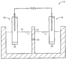
- FIG. 1 is a cross-sectional view of an organic photoelectric conversion device 10 according to the first embodiment of the present invention.
- FIG. 2 is a diagram illustrating a device configuration of the cell 12 according to the first embodiment of the present invention.
- FIG. 3 is a diagram showing the electrochemical configuration of the cell 12 in the first embodiment of the present invention.
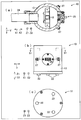
- FIG. 4 is a diagram illustrating the configuration of the organic photoelectric conversion device 10 according to the first embodiment of the present invention.
- FIG. 5 is a diagram showing an ultraviolet-visible-near infrared absorption spectrum 28 of the solution 11 with respect to a change in the light irradiation time in the first embodiment of the present invention.
- FIG. 1 is a cross-sectional view of an organic photoelectric conversion device 10 according to the first embodiment of the present invention.
- FIG. 2 is a diagram illustrating a device configuration of the cell 12 according to the first embodiment of the present invention.
- FIG. 3 is a diagram showing the electrochemical configuration of the cell 12 in the first embodiment of the present
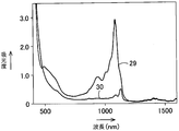
- FIG. 6 is a diagram showing an ultraviolet-visible-near infrared absorption spectrum of the solution 11 under oxygen deaeration and in the presence of dissolved oxygen in the first embodiment of the present invention.
- FIG. 7 is a diagram illustrating an electron spin resonance spectrum (ESR spectrum) of the solution 11 after the solution 11 is irradiated with light in the first embodiment of the present invention.
- FIG. 8 is a flowchart showing the steps of the organic photoelectric conversion method in the first embodiment of the present invention.
- FIG. 9 is a diagram illustrating an electrochemical configuration of the cell 12 in the organic photoelectric conversion device 10 according to the second embodiment of the present invention.
- FIG. 1 is a cross-sectional view of an organic photoelectric conversion device 10 according to the first embodiment of the present invention.
- FIG. 1A shows the organic photoelectric conversion device 10 as viewed from the side Y, with a part of the housing 13 cut away, and
- FIG. 1B shows the organic photoelectric conversion device 10 from the rear X2. As seen, a part of the housing 13 is cut away.
- FIG. 2 is a diagram illustrating a device configuration of the cell 12 according to the first embodiment of the present invention.
- FIG. 3 is a diagram showing the electrochemical configuration of the cell 12 in the first embodiment of the present invention.
- the organic photoelectric conversion device 10 is a device that uses organic molecules to convert the energy of irradiated light into electrical energy.
- the organic photoelectric conversion device 10 includes a solution 11, a cell 12, a housing 13, an anode electrode 14, and a cathode electrode 16.
- the solution 11 contains a fullerene analog 17 and an electron donor 18 as solutes.
- the electron donor 18 donates electrons to the excited fullerene analog 17 by an irreversible reaction.
- the cell 12 holds the solution 11, and the housing 13 stores the solution 11. Further, the housing 13 can selectively switch between prevention and tolerance of dissolution of oxygen in the solution 11. Further, the housing allows the solution 11 to be irradiated with light in a state where the dissolution of oxygen in the solution 11 is prevented. The light that is allowed to be irradiated to the solution 11 by the housing 13 can excite the fullerene analog 17.
- the anode electrode 14 is an electrode for taking out electrons from the anion of the fullerene analog 17, and the cathode electrode 16 is an electrode for supplying electrons to the solution 11. Electrons are donated to the anode electrode 14 through molecular oxygen.
- Organic photoelectric conversion device 10 includes cell 12, and cell 12 holds solution 11.
- the cell 12 is disposed in the housing and includes an anode electrode 14, a cathode electrode 16, and a partition plate 15.
- the anode electrode 14 and the cathode electrode 16 are configured as electrodes that partially include the aqueous phase 20.
- An oil phase 19 and an aqueous phase 20 are formed in the cell 12, and the oil phase 19 and the aqueous phase 20 are partitioned by a partition plate 15.
- One or more communication holes 21 are formed in the partition plate 15 to communicate the space on the oil phase 19 side and the space on the water phase 20 side.
- the thickness of the partition plate 15 and the size of the communication hole 21 are set so that the oil phase 19 and the water phase 20 form an interface at the boundary between each other by surface tension.
- a member that closes the communication hole 21 is provided, and communication between the oil phase 19 and the water phase 20 through the communication hole 21 and blocking of the communication are set to be switchable.
- the organic photoelectric conversion device 10 is placed in an environment without vibration.
- the communication hole 21 may have an inner diameter of about 1 mm.
- the casing 13 is further formed with rubber legs 22. When the casing 13 is placed on the floor surface, the rubber legs 22 are disposed in contact with the floor surface, and the rubber legs 22 allow the casing to be externally provided. The vibration transmitted to 13 is suppressed.
- the oil phase 19 contains fullerene C 60 (hereinafter referred to as “C 60 ”) and tetraphenyl borate as solutes, and nitrobenzene as a solvent.
- the solvent may be orthodichlorobenzene.
- C 60 in the oil phase 19 is 1 millimole (abbreviation “mM” or “mmol / dm 3 ”).
- the counter cation of tetraphenylborate was tetraoctylammonium.
- the counter cation of tetraphenylborate may be tetrabutylammonium.
- tetraphenylborate and its counter cation also have a function as a supporting electrolyte.
- the fullerene analog 17 is the fullerene C 60 , but the fullerene analog 17 is not limited thereto.
- it may be any of many types of fullerenes such as football-shaped C 78 and C 96, and may be a lower carbon nanotube that is soluble in an aromatic organic solvent.
- a colloidal material may be used as long as it can be permanently dispersed in a solvent.
- each substance is indicated by a chemical formula or an abbreviation.
- NaTPB represents sodium tetraphenylborate
- TOATPB represents tetraoctylammonium tetraphenylborate.
- the solvent is shown in parentheses.
- NB represents nitrobenzene and W represents water.
- the cathode electrode 16 partially immersed in the oil phase 19 has a glass tube closed by the salt bridge 23, and the axis line is located in the lower Z2 in the internal space of the glass tube arranged in the vertical direction Z. Is arranged with a water phase containing 10 mM lithium chloride (LiCl) and 10 mM tetraphenylborate sodium salt, and the lower Z2 of the internal space is blocked by the salt bridge 23. A water phase containing 10 mM lithium chloride (LiCl) is disposed in the upper Z1 of the internal space of the glass tube. A silver wire having a silver chloride (AgCl) film formed on the surface thereof is disposed inside the glass tube of the cathode electrode 16.
- a part of the anode electrode 14 is immersed in the aqueous phase 20 adjacent to the oil phase 19 via the partition plate 15, and the anode electrode 14 has a glass tube closed by a salt bridge 23.
- the glass tube has an axis arranged in a substantially vertical direction Z, and a water phase containing 10 mM lithium chloride (LiCl) is arranged in the internal space.
- a silver wire having a silver chloride (AgCl) film formed on the surface is disposed inside the anode electrode 14.
- FIG. 4 is a diagram illustrating a configuration of the organic photoelectric conversion device 10 according to the first embodiment of the present invention.
- 4A is a cross-sectional view showing a part of the housing 13 cut away when viewed from the upper side Z1, and FIG. 4B is a side view viewed from the rear X2, and FIG. ) Is a bottom view.
- FIG. 4A is a cross-sectional view of the organic photoelectric conversion device 10 taken along the cutting plane line S1-S1 shown in FIG. 4B.
- the direction from the cell 12 toward the optical path structure 24 is defined as the front X1, and the opposite direction is defined as the rear X2.
- the organic photoelectric conversion device 10 further includes a light irradiation unit.
- the light irradiation unit includes a light source (not shown) and an optical path configuration body 24 that configures an optical path from the light source to the cell 12. Although the optical path allows light to pass from the outside of the housing 13 into the housing 13, environmental gas outside the housing 13 is prevented from entering the housing 13.
- a xenon flash Xe flash
- Xe flash xenon flash
- the light transmitted through the cell 12 is configured to be able to observe the wavelength spectrum outside the housing 13 through the light beam passing window 26 provided in the rear X2.
- the light passage window 26 is formed of, for example, colorless and transparent sapphire. Thereby, even if the inside of the housing 13 is evacuated, it can withstand the pressure of the environmental gas, here atmospheric pressure.
- a gas flow connector 27 is formed in the housing 13, and the gas in the housing 13 can be taken in and out using the gas flow connector 27 as a passage.
- the electron donor 18 is a chemical species that can donate electrons to the fullerene analog 17 in an excited state in which one electron transition is made to the LUMO (lowest unoccupied molecular orbital) of the fullerene analog 17.
- C 60 ground state molecules are irradiated with light, they are in an excited state, and are in a high energy state corresponding to the excitation energy.
- the excitation energy ⁇ E corresponds to a value of “(wavelength of the peak of the absorption spectrum on the longest wavelength side (nm) + wavelength of the peak of the fluorescence spectrum on the shortest wavelength side (nm)) / 2”.
- the peak wavelength of the fluorescence spectrum on the shortest wavelength side is equal to or longer than the peak wavelength of the absorption spectrum on the longest wavelength side.
- Most wavelength of the peak of the absorption spectrum on the longer wavelength side of the C 60 is because it is near 650 nm, excitation energy ⁇ E of C 60 is at least 1.9eV or more.
- the reduction potential of C 60 is approximately ⁇ 0.98 eV (in toluene / acetonitrile) when a ferrocene / ferrocene radical cation is used as a reference electrode. Therefore, a molecule having an oxidation potential of 0.97 eV or more on the basis of ferrocene / ferrocene radical cation can be an electron donor 18.
- the oxidation-reduction potential when ferrocene / ferrocene radical cation is used as a reference electrode is x (eV)
- the oxidation-reduction potential when Ag / AgNO 3 is used as a reference electrode is x + 0.238 (eV).
- saturated calomel electrode abbreviated as “SCE”.
- SCE saturated calomel electrode
- the redox potential when x is 0.5 + 28 (eV)
- the redox potential when Ag / AgCl is the reference electrode is x + 0.571 (eV)
- the normal hydrogen electrode Abbreviation “NHE”) as a reference electrode
- the redox potential is x + 0.77 (eV).
- FIG. 5 is a diagram showing an ultraviolet-visible-near infrared absorption spectrum 28 of the solution 11 with respect to a change in light irradiation time in the first embodiment of the present invention.
- FIG. 6 is a diagram showing an ultraviolet-visible-near infrared absorption spectrum of the solution 11 under oxygen deaeration and in the presence of dissolved oxygen in the first embodiment of the present invention.
- a spectrum 29 similar to the raised spectrum of FIG. 5 represents the spectrum of the solution 11 under oxygen deaeration
- a spectrum 30 similar to the spectrum before the elevation of FIG. 5 represents the solution 11 in the presence of dissolved oxygen. Represents the spectrum of.
- FIG. 6 represents an ultraviolet-visible-near infrared absorption spectrum 28 of the solution 11 with respect to a change in light irradiation time in the first embodiment of the present invention.
- FIG. 6 is a diagram showing an ultraviolet-visible-near infrared absorption spectrum of the solution 11 under oxygen deaeration and in the presence of dissolved
- FIG. 7 is a diagram illustrating an electron spin resonance spectrum (ESR spectrum) of the solution 11 after the solution 11 is irradiated with light in the first embodiment of the present invention.
- FIG. 7 shows an ESR spectrum of the solution 11 under oxygen deaeration and in the presence of dissolved oxygen.
- an ESR spectrum 31 shown at the top of the paper represents the ESR spectrum of the solution 11 under oxygen deaeration
- an ESR spectrum 32 shown at the bottom of the paper represents the ESR spectrum of the solution 11 in the presence of dissolved oxygen.
- the electron donor 18 is at least one chemical species selected from tetraphenylborate anion, triphenylbutylborate anion, and tetradiamineethylene.
- tetraphenylborate anion triphenylbutylborate anion
- tetradiamineethylene tetraphenylborate anion
- Tetraphenylborate After electron transfer from tetraphenylborate anion to C 60 in an excited state, Tetraphenylborate has been suggested to be converted to biphenyl and triphenylboron.
- FIG. 8 is a flowchart showing the steps of the organic photoelectric conversion method in the first embodiment of the present invention.
- the organic photoelectric conversion method in 1st Embodiment uses the said organic photoelectric conversion apparatus 10, and includes a deaeration process, a light irradiation process, and an oxygen supply process.
- the degassing step the dissolved oxygen in the solution 11 is degassed.
- the light irradiation step the solution 11 is irradiated with light in a state where the housing 13 prevents the dissolution of oxygen in the solution 11.
- the light irradiated in the light irradiation process can excite the fullerene analog 17.
- molecular oxygen is supplied to the solution 11.
- step a1 deaeration step to perform oxygen deaeration.
- a low pressure stage in which the gas in the housing 13 is sucked out of the housing 13 by a vacuum pump to reduce the pressure of the gas in the housing 13, and an inert gas such as nitrogen and argon is supplied to the housing 13.
- the dissolved oxygen in the solution 11 held in the cell 12 is removed by repeating the pressure return step supplied into the cell 12.
- the process proceeds to the light irradiation step of step a2, and the cell 12 is irradiated with light.
- the cell 12 is irradiated with light using a light irradiation unit, that is, the light source and the optical path structure 24, to generate C 60 radical anions.
- a light irradiation unit that is, the light source and the optical path structure 24, to generate C 60 radical anions.
- light energy is stored as chemical energy. Since this can be taken out as electric energy as will be described later, this state is a state of being charged.
- step a3 the process proceeds to the communication process of step a3, and the contact between the oil phase 19 and the water phase 20 is allowed by removing the member that blocks the communication hole 21.
- the member that closes the communication holes 21 blocks all the communication holes 21 in a state before the communication step, thereby preventing contact between the oil phase 19 and the water phase 20. is doing.
- the communication step the oil phase 19 and the water phase 20 are brought into contact with each other by removing at least one member that blocks all or a part of the communication holes 21. As a result, an electromotive force is generated at the interface between the oil phase 19 and the water phase 20.
- oxygen is supplied to the solution 11.
- Oxygen may increase the oxygen concentration of the solution 11 by allowing the gas containing oxygen in the external space of the housing 13, that is, air, to enter the housing 13.
- the oxygen concentration of the solution 11 may be increased by bubbling or bubbling oxygen.
- oxygen may be supplied so as to be dissolved in the oil phase 19, it is important that the oxygen be dissolved in the water phase 20, and the dissolved oxygen in the water phase 20 efficiently converts the electrons from C60 ⁇ ⁇ . Accept.
- the contact between the solution and atmospheric air is controlled to be adjustable.
- C 60 ⁇ dissolved oxygen - adjusting the concentration of electron acceptor that receives electrons from, C 60 ⁇ - is important to adjust the speed of the oxidation reaction of the anion of the fullerene analogues 17 like.
- the communication process in step a3 and the oxygen supply process in step a4 the communication process is performed first in the first embodiment, but in other embodiments, the oxygen supply process is performed before the communication process. May be. In this case, an electromotive force is generated at the interface between the oil phase 19 and the water phase 20 by performing the communication process.
- Electron transfer of molecular oxygen from C 60 ⁇ ⁇ occurs at the interface between the oil phase 19 and the water phase 20.
- Molecular oxygen is the electron donor in the aqueous phase 20, OH - it is O 2 ⁇ - so stable than species that, OH - is considered to become.
- the chemical formula for this reaction is C 60 ⁇ ⁇ + (1/4) O 2 + (1/2) H 2 O ⁇ C 60 + OH ⁇ (2) Equation (2) is obtained.
- the dissolved oxygen in the aqueous phase 20 is 300 ⁇ M (micromoles per litter, abbreviation “ ⁇ M”). Although it can be dissolved up to a moderate concentration, the reaction rate and the electron transfer rate can be increased by setting the concentration of dissolved oxygen high, though it includes an electron transfer reaction via the interface. Thereby, sufficient electromotive force can be ensured.
- the housing 13 allows light irradiation to the solution 11 in a state where the dissolution of oxygen in the solution 11 is prevented.
- the fullerene analog 17 by irradiating the solution 11 with light in a state where the dissolution of oxygen in the solution 11 is blocked. Therefore, electrons can be donated from the electron donor 18 to the fullerene analog 17 in the excited state, and an anion of the fullerene analog 17 can be generated. Since the anion of the fullerene analog 17 has a lifetime of several hundred hours or more in the absence of oxygen and is stable, the anion of the fullerene analog 17 has a higher energy state than the electrically neutral and ground state fullerene analog 17 by several hundred. Can be maintained over time. As a result, the energy provided by light irradiation can be stored as chemical energy and extracted as electrical energy. Thereby, it can be stored by light irradiation.
- the electron donor 18 donates electrons to the excited fullerene analog 17 by an irreversible reaction. Accordingly, it is possible to prevent reverse electron transfer from occurring after photoinduced electron transfer from the electron donor 18 to the fullerene analog 17 is caused by light irradiation. Therefore, the anion of the fullerene analog 17 can be maintained sufficiently stably.
- electrons are provided to the anode electrode 14 through molecular oxygen.
- molecular oxygen can function as an electron transfer medium. Since molecular oxygen can accept electrons from the anion of the fullerene analog 17 and is abundant in the air, the housing 11 prevents or allows dissolution of the environmental gas in the solution 11 by the housing. It is possible to switch whether or not the electron transmission medium can enter.
- the electron donor 18 is a substance that can donate electrons to the excited fullerene analog 17 in which one electron transitions to the LUMO of the fullerene analog 17.
- the anion of the fullerene analog 17 can be generated. Even if the fullerene analog 17 in the excited state transitions to an orbital having an energy level higher than that of LUMO, it becomes an excited state in which one electron has transitioned to LUMO due to relaxation. By allowing the electron donor 18 to donate electrons to the analog 17, an anion of the fullerene analog 17 can be generated.
- the electron donor 18 is at least one chemical species selected from tetraphenylborate anion, triphenylbutylborate anion, and tetradiamineethylene.
- the anion of the fullerene analog 17 can be generated.
- Tetraphenylborate anion, triphenylbutylborate anion, and tetradiamineethylene are chemical species that can donate electrons to excited fullerene analog 17 that has undergone one-electron transition. , Electrons can be donated to the fullerene analog 17.
- the dissolved oxygen in the solution 11 is degassed.
- the solution 11 is irradiated with light in a state where the housing 13 prevents the dissolution of oxygen in the solution 11.
- the light irradiated in the light irradiation process can excite the fullerene analog 17.
- molecular oxygen is supplied to the solution 11.
- the communication hole 21 is maintained in a closed state before the discharge is started.
- C 60 ⁇ produced by photoinduced electron transfer - as electron acceptor which accepts electrons from the molecular oxygen to receive efficiently electrons.
- an electron acceptor that accepts electrons from C 60 ⁇ ⁇ water molecules may also contribute, and in the electron transfer after the photo-induced electron transfer, another type of chemical species is an electron acceptor. It may be functioning as
- FIG. 9 is a diagram illustrating an electrochemical configuration of the cell 12 in the organic photoelectric conversion device 10 according to the second embodiment of the present invention.
- the organic photoelectric conversion device 10 according to the second embodiment is similar to the organic photoelectric conversion device 10 according to the first embodiment, and will be described below with a focus on differences between the second embodiment and the first embodiment.
- the oil phase 19 in the cell 12 is the same as in the first embodiment.
- the aqueous phase 20 contains 10 mM tetrabutylammonium chloride as a supporting electrolyte.
- the anode electrode 14 is a silver electrode having a silver chloride (AgCl) film formed on the surface thereof.
- the cathode electrode 16 is platinum (Pt). Also by this, the same photoinduced electron transfer reaction as in the first embodiment can be caused in the oil phase 19.
- the chemical species of C 60 ⁇ ⁇ can be maintained.
- concentration of dissolved oxygen in the aqueous phase 20 is increased, molecular oxygen is mediated through Is discharged.
- the anode electrode 14 and the cathode electrode 16 are not limited to the embodiments shown in the first and second embodiments.
- the water phase 20 that is in contact with the oil phase 19 via the interface is used, but in other embodiments, the water phase 20 is omitted and the anode electrode 14 is a p-type.
- a semiconductor may be an n-type semiconductor as the cathode electrode 16.
- tetraphenylborate and its counter cation also have a function as a supporting electrolyte.
- copper iodide (CuI) can be used as a supporting electrolyte.
- the receptor of succeeding electronic than photoinduced electron transfer in particular C 60 ⁇ - electron acceptor from, but a configuration has been described in which the molecular oxygen, an electron-accepting
- the electron acceptor to be used is not limited to molecular oxygen. It is also possible to transfer water molecules and other types of molecules depending on the electromotive force required.
- the organic photoelectric conversion device and the organic photoelectric conversion method using the same according to the present invention can convert light energy into an energy form that can be taken out as electric energy, and can be stored as electric energy so that it can be taken out.
- the present invention is useful as an organic photoelectric conversion device that converts energy of light irradiated using organic molecules into electric energy, an organic photoelectric conversion method using the same, and the like.
Landscapes
- Engineering & Computer Science (AREA)
- Chemical & Material Sciences (AREA)
- Power Engineering (AREA)
- Nanotechnology (AREA)
- General Chemical & Material Sciences (AREA)
- Physics & Mathematics (AREA)
- Mathematical Physics (AREA)
- Theoretical Computer Science (AREA)
- Crystallography & Structural Chemistry (AREA)
- Electrochemistry (AREA)
- Materials Engineering (AREA)
- Chemical Kinetics & Catalysis (AREA)
- Microelectronics & Electronic Packaging (AREA)
- Hybrid Cells (AREA)
- Photovoltaic Devices (AREA)
Abstract
有機光電変換装置10において、溶液11は、フラーレン類縁体17と、エレクトロンドナー18とを溶質として含有する。筐体13は、溶液11に対する酸素の溶解の阻止および許容を選択的に切換可能である。また筐体は、前記溶液11に対する酸素の溶解が阻止された状態で、溶液11に対する光の照射を許容する。アノード電極14は、フラーレン類縁体17のアニオンからの電子を取出すための電極であり、カソード電極16は、前記溶液11に電子を供給するための電極である。
Description
本発明は、有機分子を用い、照射される光のエネルギを電気エネルギに変換する有機光電変換装置およびこれを用いる有機光電変換方法に関する。
従来技術に係る有機光電変換装置として、酸化亜鉛薄膜からなる透明電極と、フラーレンを含む複数種類の物質から選ばれる有機光伝導性媒質とを積層して形成される有機太陽電池が知られる(たとえば特許文献1参照)。
従来技術に係る有機光電変換装置では、光エネルギから電気エネルギに変換することはできるけれども、蓄電池として利用できないという問題点がある。また取出した電気エネルギを蓄電するためには、別途、蓄電のための装置が必要になるという問題点がある。
本発明の目的は、光エネルギを、電気エネルギとして取出すことの可能なエネルギ形態に変換し、かつ電気エネルギとして、取出し可能に蓄積することのできる有機光電変換装置、およびこれを用いる有機光電変換方法を提供することである。
本発明は、フラーレン類縁体と、励起状態のフラーレン類縁体に対して電子を供与するエレクトロンドナーとを溶質として含有する溶液と、
前記溶液を保持するセルと、
前記セルを収容する筐体であって、前記フラーレン類縁体を励起可能な光の前記溶液に対する照射を許容する筐体と、
前記フラーレン類縁体のアニオンからの電子を取出すためのアノード電極と、
前記溶液に電子を供給するためのカソード電極とを含むことを特徴とする有機光電変換装置である。
前記溶液を保持するセルと、
前記セルを収容する筐体であって、前記フラーレン類縁体を励起可能な光の前記溶液に対する照射を許容する筐体と、
前記フラーレン類縁体のアニオンからの電子を取出すためのアノード電極と、
前記溶液に電子を供給するためのカソード電極とを含むことを特徴とする有機光電変換装置である。
また本発明は、前記エレクトロンドナーは、励起状態の前記フラーレン類縁体に対して不可逆反応によって電子を供与することを特徴とする。
また本発明は、前記アノード電極には、分子状酸素を介して電子が供与され、
前記筐体は、前記溶液に対する酸素の溶解の阻止および許容を選択的に切換可能であり、かつ前記溶液に対する光の照射を、溶液に対する酸素の溶解が少なくとも阻止された状態において許容することを特徴とする。
前記筐体は、前記溶液に対する酸素の溶解の阻止および許容を選択的に切換可能であり、かつ前記溶液に対する光の照射を、溶液に対する酸素の溶解が少なくとも阻止された状態において許容することを特徴とする。
また本発明は、前記エレクトロンドナーは、フラーレン類縁体のLUMOに1電子遷移した励起状態のフラーレン類縁体に対して電子を供与可能な物質であることを特徴とする。
また本発明は、エレクトロンドナーは、テトラフェニルボレートアニオン、トリフェニルブチルボレートアニオン、およびテトラジアミンエチレンのうちから選ばれる少なくとも1種の物質であることを特徴とする。
また本発明は、前記有機光電変換装置を用い、
前記溶液の溶存酸素を脱気する脱気工程と、
前記筐体によって、前記溶液に対する酸素の溶解が阻止された状態で、前記溶液に、前記フラーレン類縁体を励起可能な光を照射する光照射工程と、
前記溶液に、分子状酸素を供給する酸素供給工程とを含むことを特徴とする有機光電変換方法である。
前記溶液の溶存酸素を脱気する脱気工程と、
前記筐体によって、前記溶液に対する酸素の溶解が阻止された状態で、前記溶液に、前記フラーレン類縁体を励起可能な光を照射する光照射工程と、
前記溶液に、分子状酸素を供給する酸素供給工程とを含むことを特徴とする有機光電変換方法である。
本発明によれば、有機光電変換装置は、溶液と、セルと、筐体と、アノード電極と、カソード電極とを含んで構成される。溶液は、フラーレン類縁体と、エレクトロンドナーとを溶質として含有する。エレクトロンドナーは、励起状態のフラーレン類縁体に対して電子を供与する。セルは、前記溶液を保持し、筐体は、前記セルを収容する。また筐体は、溶液に対する光の照射を許容する。溶液に対する照射が筐体によって許容される光は、前記フラーレン類縁体を励起可能である。アノード電極は、フラーレン類縁体のアニオンからの電子を取出すための電極であり、カソード電極は、前記溶液に電子を供給するための電極である。
これによって、溶液に光を照射し、フラーレン類縁体を励起させることが可能となる。したがって、励起状態のフラーレン類縁体に対してエレクトロンドナーから電子を供与し、フラーレン類縁体のアニオンを充分安定に生成することができる。フラーレン類縁体のアニオンは、数百時間以上の寿命を有し安定であるので、電気的に中性かつ基底状態のフラーレン類縁体よりも高エネルギ状態を、数百時間以上にわたって維持することができる。これによって、光照射によって供与されたエネルギを化学エネルギとして蓄積し、電気エネルギとして取出すことが可能となる。これによって光照射によって蓄電することができる。
また本発明によれば、エレクトロンドナーは、励起状態のフラーレン類縁体に対して不可逆反応によって電子を供与する。これによって、光照射によってエレクトロンドナーからフラーレン類縁体に対して光誘起電子移動が生じた後、逆電子移動が生じることを阻止することができる。したがって、フラーレン類縁体のアニオンを充分安定に維持することができる。
また本発明によれば、アノード電極には、分子状酸素を介して電子が供与される。また筐体は、前記溶液に対する酸素の溶解の阻止および許容を選択的に切換可能であり、かつ溶液に対する酸素の溶解が少なくとも阻止された状態において、溶液に対する光の照射を許容する。これによって、分子状酸素は、電子伝達媒体として機能することができる。分子状酸素は、フラーレン類縁体のアニオンから電子を受容することができ、また空気中に豊富に存在するので、筐体によって溶液に対する環境気体の溶解を阻止または許容することによって、溶液に対する電子伝達媒体の進入の可否を切換えることができる。
また本発明によれば、エレクトロンドナーは、フラーレン類縁体のLUMOに1電子遷移した励起状態のフラーレン類縁体に対して電子を供与可能な化学種である。
これによって、フラーレン類縁体のアニオンを生成することができる。励起状態のフラーレン類縁体は、仮にLUMOよりも高いエネルギ準位の軌道に電子遷移しても、緩和によってLUMOに1電子遷移した励起状態となるので、LUMOに1電子遷移した励起状態のフラーレン類縁体に対してエレクトロンドナーが電子を供与可能であることによって、フラーレン類縁体のアニオンを生成することができる。
また本発明によれば、エレクトロンドナーは、テトラフェニルボレートアニオン、トリフェニルブチルボレートアニオン、およびテトラジアミンエチレンのうちから選ばれる少なくとも1種の化学種である。
これによって、フラーレン類縁体のアニオンを生成することができる。テトラフェニルボレートアニオン、トリフェニルブチルボレートアニオン、およびテトラジアミンエチレンは、1電子遷移した励起状態のフラーレン類縁体に対して電子を供与可能な化学種であるので、フラーレンに光照射を行うことによって、フラーレン類縁体に対して電子を供与することができる。
また本発明によれば、有機光電変換方法は、前記有機光電変換装置を用い、脱気工程と、光照射工程と、酸素供給工程とを含む。脱気工程では、溶液の溶存酸素を脱気する。光照射工程では、筐体によって、前記溶液に対する酸素の溶解が阻止された状態で、前記溶液に、光を照射する。光照射工程で照射される光は、フラーレン類縁体を励起可能である。酸素供給工程では、前記溶液に、分子状酸素を供給する。
これによって、溶液に溶存酸素がほとんどなく、溶液に対する酸素の溶解が阻止された状態で、溶液に光を照射し、フラーレン類縁体を励起させることが可能となる。したがって、励起状態のフラーレン類縁体に対してエレクトロンドナーから電子を供与し、フラーレン類縁体のアニオンを生成することができる。フラーレン類縁体のアニオンは、酸素非存在下では数百時間以上の寿命を有し安定であるので、電気的に中性かつ基底状態のフラーレン類縁体よりも高エネルギな状態を、数百時間以上にわたって維持することができる。これによって、光照射によって供与されたエネルギを化学エネルギとして蓄積し、電気エネルギとして取出すことが可能となる。したがって光照射によって蓄電し、蓄電の後に放電することができる。
以下、図面を参照しながら、本発明を実施するための複数の形態について説明する。以下の説明においては、各形態に先行する形態ですでに説明している事項に対応している部分には同一の参照符を付し、重複する説明を略す場合がある。構成の一部のみを説明している場合、構成の他の部分は、先行して説明している形態と同様とする。実施の各形態で具体的に説明している部分の組合せばかりではなく、特に組合せに支障が生じなければ、実施の形態同士を部分的に組合せることも可能である。またそれぞれの実施形態は、本発明に係る技術を具体化するために例示するものであり、本発明の技術的範囲を限定するものではない。本発明に係る技術内容は、特許請求の範囲に記載された技術的範囲内において、種々の変更を加えることが可能である。以下の説明は、有機光電変換装置10および有機光電変換方法についての説明を含む。
(第1実施形態)
図1は、本発明の第1実施形態に係る有機光電変換装置10の断面図である。図1(a)は、有機光電変換装置10を側方Yから見て、筐体13の一部を切り欠いて示しており、図1(b)は、有機光電変換装置10を後方X2から見て、筐体13の一部を切り欠いて示している。図2は、本発明の第1実施形態におけるセル12の装置構成を表す図である。図3は、本発明の第1実施形態におけるセル12の電気化学的な構成を表す図である。有機光電変換装置10は、有機分子を用い、照射される光のエネルギを電気エネルギに変換する装置である。
図1は、本発明の第1実施形態に係る有機光電変換装置10の断面図である。図1(a)は、有機光電変換装置10を側方Yから見て、筐体13の一部を切り欠いて示しており、図1(b)は、有機光電変換装置10を後方X2から見て、筐体13の一部を切り欠いて示している。図2は、本発明の第1実施形態におけるセル12の装置構成を表す図である。図3は、本発明の第1実施形態におけるセル12の電気化学的な構成を表す図である。有機光電変換装置10は、有機分子を用い、照射される光のエネルギを電気エネルギに変換する装置である。
第1実施形態において、有機光電変換装置10は、溶液11と、セル12と、筐体13と、アノード電極14と、カソード電極16とを含んで構成される。溶液11は、フラーレン類縁体17と、エレクトロンドナー18とを溶質として含有する。エレクトロンドナー18は、励起状態のフラーレン類縁体17に対して不可逆反応によって電子を供与する。セル12は、前記溶液11を保持し、筐体13は、前記溶液11を収容する。また筐体13は、溶液11に対する酸素の溶解の阻止および許容を選択的に切換可能である。また筐体は、前記溶液11に対する酸素の溶解が阻止された状態で、溶液11に対する光の照射を許容する。溶液11に対する照射が筐体13によって許容される光は、前記フラーレン類縁体17を励起可能である。アノード電極14は、フラーレン類縁体17のアニオンからの電子を取出すための電極であり、カソード電極16は、前記溶液11に電子を供給するための電極である。アノード電極14には、分子状酸素を介して電子が供与される。
有機光電変換装置10は、セル12を含み、セル12は、溶液11を保持する。セル12は筐体内に配置され、アノード電極14、カソード電極16および仕切板15を含む。アノード電極14およびカソード電極16は、一部に水相20を含む電極として構成される。セル12には、油相19と水相20とが形成され、油相19と水相20とは、仕切板15によって仕切られている。仕切板15には、油相19側の空間と水相20側の空間とを連通する連通孔21が1つ以上形成される。仕切板15の厚み、および連通孔21の大きさは、油相19および水相20が、表面張力によって互いの境界に界面を形成するように設定される。また第1実施形態では、連通孔21を塞ぐ部材が設けられ、連通孔21による油相19および水相20間の連通と、この連通の阻止とを切換可能に設定される。
第1実施形態において有機光電変換装置10は、振動のない環境下で載置される。具体的には、連通孔21の内径は、1mm程度に形成されてもよい。筐体13には、さらにゴム脚22が形成され、筐体13を床面に載置したときには、床面に対してゴム脚22が接触して配置され、ゴム脚22によって、外部から筐体13に伝達される振動を抑制する。
油相19には、カソード電極16の一部が浸漬され、水相20には、アノード電極14の一部が浸漬される。油相19は、フラーレンC60(以下「C60」と称する)と、テトラフェニルボレートとを溶質として含有し、ニトロベンゼンを溶媒として含む。他の実施形態では、溶媒は、オルトジクロロベンゼンであってもよい。第1実施形態において油相19中のC60は1ミリモーラ(millimoles per litter, 略号「mM」または「mmol/dm3」)とした。テトラフェニルボレートのカウンタカチオンは、テトラオクチルアンモニウムとした。他の実施形態においてテトラフェニルボレートのカウンタカチオンは、テトラブチルアンモニウムであってもよい。油相19中において、テトラフェニルボレートおよびそのカウンタカチオンは、支持電解質としての機能をも有する。
第1実施形態においてフラーレン類縁体17は、フラーレンC60であるものとしたけれども、フラーレン類縁体17は、これに限定するものではない。たとえば、フットボール形のC78,C96など多くの種類のフラーレンのいずれでもよく、また芳香族の有機溶媒に溶解可能な低級のカーボンナノチューブであってもよい。溶媒中で永続的に分散できれば、コロイドをなすものであってもよい。
図3において、各物質は化学式または略称によって示している。NaTPBは、ナトリウム テトラフェニルボレートを表し、TOATPBは、テトラオクチルアンモニウム テトラフェニルボレートを意味している。また各相において括弧内には溶媒を示す。NBは、ニトロベンゼンを表し、Wは水を表している。
油相19に一部が浸漬されているカソード電極16は、塩橋23によって塞がれたガラス管を有し、軸線をほぼ鉛直方向Zに配置されたガラス管の内部空間のうち下方Z2には、10mMの塩化リチウム(LiCl)と10mMのテトラフェニルボレートのナトリウム塩とを含む水の相が配置され、内部空間の下方Z2は塩橋23によって塞がれる。ガラス管の内部空間のうち上方Z1には、10mMの塩化リチウム(LiCl)を含む水の相が配置される。またこのカソード電極16のガラス管の内部には、表面に塩化銀(AgCl)の膜が形成された銀製の針金が配置される。
油相19に対して仕切板15を介して隣接する水相20には、アノード電極14の一部が浸漬され、アノード電極14は、塩橋23によって塞がれたガラス管を有する。ガラス管は、軸線をほぼ鉛直方向Zに配置され、内部空間には10mMの塩化リチウム(LiCl)を含む水の相が配置される。またアノード電極14の内部には、表面に塩化銀(AgCl)の膜が形成された銀製の針金が配置される。
図4は、本発明の第1実施形態に係る有機光電変換装置10の構成を表す図である。図4(a)は、上方Z1から見て筐体13の一部を切り欠いて示した断面図であり、図4(b)は、後方X2から見た側面図であり、図4(c)は、底面図である。図4(a)は、有機光電変換装置10を、図4(b)に示す切断面線S1-S1で切断して見た断面図である。図4において、セル12から光路構成体24に向かう向きを前方X1とし、反対の向きを後方X2とする。有機光電変換装置10は、光照射部をさらに含んで構成される。光照射部は、図示していない光源と、光源からセル12までの光路を構成する光路構成体24とを含む。光路は、筐体13外から筐体13内への光の透過を許容するけれども、筐体13外の環境気体が筐体13内に進入することは阻止されている。光源は、たとえばキセノンフラッシュ(Xeフラッシュ)を用いることができる。
本実施形態では、セル12を透過した光は、後方X2に設けられた光線通過窓26を透過して筐体13外において、その波長スペクトルを観測できるように構成されている。光線通過窓26は、たとえば無色透明なサファイアによって形成される。これによって、筐体13内を真空にしても、環境気体の圧力、ここでは大気圧に耐えることができる。筐体13には、気体流通用コネクタ27が形成され、気体流通用コネクタ27を通路として、筐体13内の気体を出し入れすることができる。
エレクトロンドナー18は、フラーレン類縁体17のLUMO(lowest unoccupied molecular orbital)に1電子遷移した励起状態のフラーレン類縁体17に対して電子を供与可能な化学種である。C60の基底状態の分子が光照射されると励起状態となり、励起エネルギの分、高エネルギな状態となる。励起エネルギΔEは、「(最も長波長側の吸収スペクトルのピークの波長(nm)+最も短波長側の蛍光スペクトルのピークの波長(nm))/2」の値に対応する。これを「励起波長(nm)」と称すると、励起エネルギΔE(eV)は、
ΔE(eV)=1240/励起波長(nm) …(1)
式(1)のように算出される。
ΔE(eV)=1240/励起波長(nm) …(1)
式(1)のように算出される。
励起に寄与する電子遷移については、ストークスシフトの現象があるので、最も短波長側の蛍光スペクトルのピークの波長は、最も長波長側の吸収スペクトルのピークの波長以上である。C60の最も長波長側の吸収スペクトルのピークの波長は、650nm付近であるので、C60の励起エネルギΔEは、少なくとも1.9eV以上である。C60の還元電位は、フェロセン/フェロセンラジカルカチオンを参照電極としたときに、およそ-0.98eV(トルエン/アセトニトリル中)である。したがって、フェロセン/フェロセンラジカルカチオン基準で酸化電位が0.97eV以上である分子は、エレクトロンドナー18となり得る。
フェロセン/フェロセンラジカルカチオンを参照電極としたときの酸化還元電位をx(eV)とすると、Ag/AgNO3を参照電極としたときの酸化還元電位は、x+0.238(eV)となり、カロメル電極(saturated calomel electrode, 略称「SCE」)
を参照電極としたときの酸化還元電位は、x+0.528(eV)となり、Ag/AgClを参照電極としたときの酸化還元電位は、x+0.571(eV)となり、標準水素電極(normal hydrogen electrode, 略称「NHE」)を参照電極としたときの酸化還元電
位は、x+0.77(eV)となる。
を参照電極としたときの酸化還元電位は、x+0.528(eV)となり、Ag/AgClを参照電極としたときの酸化還元電位は、x+0.571(eV)となり、標準水素電極(normal hydrogen electrode, 略称「NHE」)を参照電極としたときの酸化還元電
位は、x+0.77(eV)となる。
図5は、本発明の第1実施形態において光照射時間の変化に対する溶液11の紫外-可視-近赤外吸収スペクトル28を表す図である。図6は、本発明の第1実施形態において酸素脱気下および溶存酸素存在下における溶液11の紫外-可視-近赤外吸収スペクトルを表す図である。図6において、図5の隆起したスペクトルに類似するスペクトル29は、酸素脱気下における溶液11のスペクトルを表し、図5の隆起前のスペクトルに類似するスペクトル30は、溶存酸素存在下における溶液11のスペクトルを表す。図7は、本発明の第1実施形態において、溶液11に光照射を行った後の、溶液11の電子スピン共鳴スペクトル(ESRスペクトル)を表す図である。図7には、酸素脱気下および溶存酸素存在下における溶液11のESRスペクトルを表している。図7において、紙面上方に示されたESRスペクトル31は、酸素脱気下における溶液11のESRスペクトルを表し、紙面下方に示されたESRスペクトル32は、溶存酸素存在下における溶液11のESRスペクトルを表す。
エレクトロンドナー18は、テトラフェニルボレートアニオン、トリフェニルブチルボレートアニオン、およびテトラジアミンエチレンのうちから選ばれる少なくとも1種類の化学種である。たとえば、「J.Chem.Soc.,PERKIN Trans.2,1999,551-556,Konishi,and Ito etal」には、励起状態のC60に対してテトラフェニルボレートアニオンから電子移動が生じたのち、テトラフェニルボレートは、ビフェニルおよびトリフェニルボロンに変換されることが示唆されている。
C60に対して電子供与したのちのテトラフェニルボレートは、C60に対して付加することも考えられるけれども、C60に対して大きな割合でフラーレンC60のラジアルアニオン(C60
・-)の生成が確認され、かつ数百時間という時間変化に対して安定なC60
・-が観測されるので、C60に対する何らかの化学種の付加は、分量としてわずかであるものと予想される。
図5に示すように、酸素脱気下において、油相19に対する光照射を長くすれば長くするほどC60
・-に特有の吸収スペクトルの増大が確認される。図6に示すように、酸素脱気下という状態を維持すれば、C60
・-に特有の吸収スペクトルも数百時間という寿命で維持される。しかし酸素をバブリングなどによって混入させると、C60
・-に特有の吸収スペクトルは、減衰し消滅する。また図7に示すように、酸素脱気下という状態を維持すれば、C60
・-に特有のESRスペクトルも数百時間という寿命で維持される。しかし酸素をバブリングなどによって混入させると、C60
・-に特有のESRスペクトルは、減衰し消滅する。
図8は、本発明の第1実施形態における有機光電変換方法の工程を表すフローチャートである。第1実施形態における有機光電変換方法は、前記有機光電変換装置10を用い、脱気工程と、光照射工程と、酸素供給工程とを含む。脱気工程では、溶液11の溶存酸素を脱気する。光照射工程では、筐体13によって、前記溶液11に対する酸素の溶解が阻止された状態で、前記溶液11に、光を照射する。光照射工程で照射される光は、フラーレン類縁体17を励起可能である。酸素供給工程では、前記溶液11に、分子状酸素を供給する。
本処理は、前述の有機光電変換装置10を準備し、外部からの光が溶液11に照射されない状態を維持した状態で開始される。さらに第1実施形態においては、前記連通孔21が塞がれることによって、油相19と水相20との接触が阻止された状態で開始される。本処理開始後、ステップa1脱気工程に移行し、酸素脱気を行う。脱気工程では、真空ポンプによって筐体13内の気体を筐体13外に吸引し筐体13内の気体の圧力を小さくする低圧化段階と、窒素およびアルゴンなどの不活性ガスを筐体13内に供給する圧力復帰段階とを繰返すことによって、セル12に保持される溶液11の溶存酸素を除去する。
次にステップa2の光照射工程に移行し、セル12に対して光照射を行う。光照射工程では、光照射部、すなわち光源と光路構成体24とを用いてセル12に対して光照射し、C60のラジカルアニオンを発生させる。この状態で、光エネルギが化学エネルギとして蓄積される。これは、後述するように電気エネルギとして取出すことができるので、この状態は、蓄電された状態である。
次にステップa3の連通工程に移行し、連通孔21を塞ぐ部材を除去することによって、油相19と水相20との接触を許容する。連通孔21が複数形成される場合には、連通工程よりも前の状態では、連通孔21を塞ぐ部材は全ての連通孔21を塞ぐことによって、油相19と水相20との接触を阻止している。連通工程では、少なくとも1つ、全部または一部の連通孔21を塞ぐ部材を除去することによって、油相19と水相20とを接触させる。これによって、油相19と水相20との界面において起電力が発生する。
次にステップa4の酸素供給工程に移行し、溶液11に酸素を供給する。酸素は、筐体13の外部空間の酸素を含む気体、すなわち空気の、筐体13内への進入を許容することによって溶液11の酸素濃度を上昇させてもよいけれども、さらに積極的に、空気をバブリングする、あるいは酸素をバブリングすることによって、溶液11の酸素濃度を上昇させてもよい。また酸素は、油相19に溶存するように供給されても構わないけれども、水相20に溶存させることが重要であり、水相20の溶存酸素が、C60
・-からの電子を効率よく受容する。
酸素供給工程において、溶液と大気中の空気との接触は、調整可能に制御される。溶存酸素などC60
・-からの電子を受容するエレクトロンアクセプタの濃度を調整することは、C60
・-などフラーレン類縁体17のアニオンの酸化反応の速度を調整するためには重要である。
酸素供給工程が行われると、有機光電変換装置10では、アノード電極14に電子が供与され、溶液11には、カソード電極16を経て電子が供給される。C60
・-は、分子状酸素の還元電位よりも高い酸化電位を有するので、C60
・-から溶液11に溶存した分子状酸素に電子が供与され、C60は、基底状態の分子に戻り、高エネルギ状態ではなくなる。このようなC60
・-からの電子移動は、分子状酸素存在下という条件において自発的に起こる。このような電子移動によって、アノード電極14およびカソード電極16との間に起電力が生じ、蓄電池の放電が行われる。その後、本処理は終了する。
ステップa3の連通工程とステップa4の酸素供給工程とでは、第1実施形態においては連通工程を先に行う構成としたけれども、他の実施形態においては、酸素供給工程を連通工程よりも先に行ってもよい。この場合には、連通工程が行われることによって、油相19と水相20との界面において起電力が発生する。
C60
・-から分子状酸素の電子移動は、油相19と水相20との界面において生じる。水相20において電子供与された分子状酸素は、OH-がO2
・-という化学種よりも安定なので、OH-となると考えられる。この反応の化学式は、
C60 -・+(1/4)O2+(1/2)H2O→C60+OH- …(2)
式(2)のようになる。
C60 -・+(1/4)O2+(1/2)H2O→C60+OH- …(2)
式(2)のようになる。
水相20において溶存酸素は、300μM(micromoles per litter, 略号「μM」)
ほどの濃度まで溶解可能であるので、界面を介する電子移動反応を含むけれども、反応速度および電子移動速度は、溶存酸素の濃度を高く設定することによって大きくすることができる。これによって、充分な起電力を確保することができる。
ほどの濃度まで溶解可能であるので、界面を介する電子移動反応を含むけれども、反応速度および電子移動速度は、溶存酸素の濃度を高く設定することによって大きくすることができる。これによって、充分な起電力を確保することができる。
第1実施形態によれば、筐体13は、前記溶液11に対する酸素の溶解が阻止された状態で、溶液11に対する光の照射を許容する。これによって、溶液11に対する酸素の溶解が阻止された状態で、溶液11に光を照射し、フラーレン類縁体17を励起させることが可能となる。したがって、励起状態のフラーレン類縁体17に対してエレクトロンドナー18から電子を供与し、フラーレン類縁体17のアニオンを生成することができる。フラーレン類縁体17のアニオンは、酸素非存在下では数百時間以上の寿命を有し安定であるので、電気的に中性かつ基底状態のフラーレン類縁体17よりも高エネルギな状態を、数百時間以上にわたって維持することができる。これによって、光照射によって供与されたエネルギを化学エネルギとして蓄積し、電気エネルギとして取出すことが可能となる。これによって光照射によって蓄電することができる。
また第1実施形態によれば、エレクトロンドナー18は、励起状態のフラーレン類縁体17に対して不可逆反応によって電子を供与する。これによって、光照射によってエレクトロンドナー18からフラーレン類縁体17に対して光誘起電子移動が生じた後、逆電子移動が生じることを阻止することができる。したがって、フラーレン類縁体17のアニオンを充分安定に維持することができる。
また第1実施形態によれば、アノード電極14には、分子状酸素を介して電子が供与される。これによって、分子状酸素は、電子伝達媒体として機能することができる。分子状酸素は、フラーレン類縁体17のアニオンから電子を受容することができ、また空気中に豊富に存在するので、筐体によって溶液11に対する環境気体の溶解を阻止または許容することによって、溶液11に対する電子伝達媒体の進入の可否を切換えることができる。
また第1実施形態によれば、エレクトロンドナー18は、フラーレン類縁体17のLUMOに1電子遷移した励起状態のフラーレン類縁体17に対して電子を供与可能な物質である。これによって、フラーレン類縁体17のアニオンを生成することができる。励起状態のフラーレン類縁体17は、仮にLUMOよりも高いエネルギ準位の軌道に電子遷移しても、緩和によってLUMOに1電子遷移した励起状態となるので、LUMOに1電子遷移した励起状態のフラーレン類縁体17に対してエレクトロンドナー18が電子を供与可能であることによって、フラーレン類縁体17のアニオンを生成することができる。
また第1実施形態によれば、エレクトロンドナー18は、テトラフェニルボレートアニオン、トリフェニルブチルボレートアニオン、およびテトラジアミンエチレンのうちから選ばれる少なくとも1種類の化学種である。これによって、フラーレン類縁体17のアニオンを生成することができる。テトラフェニルボレートアニオン、トリフェニルブチルボレートアニオン、およびテトラジアミンエチレンは、1電子遷移した励起状態のフラーレン類縁体17に対して電子を供与可能な化学種であるので、フラーレンに光照射を行うことによって、フラーレン類縁体17に対して電子を供与することができる。
また第1実施形態によれば、脱気工程では、溶液11の溶存酸素を脱気する。光照射工程では、筐体13によって、前記溶液11に対する酸素の溶解が阻止された状態で、前記溶液11に、光を照射する。光照射工程で照射される光は、フラーレン類縁体17を励起可能である。酸素供給工程では、前記溶液11に、分子状酸素を供給する。
これによって、溶液11に溶存酸素がほとんどなく、溶液11に対する酸素の溶解が阻止された状態で、溶液11に光を照射し、フラーレン類縁体17を励起させることが可能となる。したがって、励起状態のフラーレン類縁体17に対してエレクトロンドナー18から電子を供与し、フラーレン類縁体17のアニオンを生成することができる。フラーレン類縁体17のアニオンは、酸素非存在下では数百時間以上の寿命を有し安定であるので、電気的に中性かつ基底状態のフラーレン類縁体17よりも高エネルギな状態を、数百時間以上にわたって維持することができる。これによって、光照射によって供与されたエネルギを化学エネルギとして蓄積し、電気エネルギとして取出すことが可能となる。したがって光照射によって蓄電し、蓄電の後に放電することができる。
さらに第1実施形態によれば、放電が開始されるよりも前の段階において、連通孔21は、塞がれた状態で維持される。これによって、光照射によってC60
・-が生成しても、油相19と水相20とが接触することは阻止されているので、水分子もC60
・-からの電子を受容するエレクトロンアクセプタとして機能することが阻止され、C60
・-を長時間、安定に維持することができる。したがって、蓄電状態を安定に保つことができる。
第1実施形態において前述したように、光誘起電子移動によって生成したC60
・-からの電子を受容するエレクトロンアクセプタとして、分子状酸素は効率よく電子を受容する。C60
・-からの電子を受容するエレクトロンアクセプタとしては、水分子も寄与している可能性があり、光誘起電子移動よりも後段の電子移動においては、さらに他の種類の化学種がエレクトロンアクセプタとして機能している可能性もある。
またフラーレン類縁体17のアニオンからの電子は、分子状酸素に供与されるけれども、フラーレン類縁体17以外の化学種に対して電子移動が生じた後、その化学種を経て分子状酸素または水分子に電子移動が生じる構成であっても構わない。光誘起電子移動よりも後段における電子移動の経路に関して限定するものではない。
(第2実施形態)
図9は、本発明の第2実施形態に係る有機光電変換装置10において、セル12の電気化学的な構成を表す図である。第2実施形態に係る有機光電変換装置10は、第1実施形態に係る有機光電変換装置10に類似しており、以下、第1実施形態に対する第2実施形態の相違点を中心に説明する。
図9は、本発明の第2実施形態に係る有機光電変換装置10において、セル12の電気化学的な構成を表す図である。第2実施形態に係る有機光電変換装置10は、第1実施形態に係る有機光電変換装置10に類似しており、以下、第1実施形態に対する第2実施形態の相違点を中心に説明する。
第2実施形態に係る有機光電変換装置10において、セル12中の油相19は、第1実施形態と同様である。水相20においては、支持電解質として10mMテトラブチルアンモニウムクロライドを含む。アノード電極14は、表面に塩化銀(AgCl)の膜が形成された銀製の電極とする。カソード電極16は、白金(Pt)とする。これによっても、油相19において第1実施形態と同様の光誘起電子移動反応を起こすことができる。水相20における酸素濃度を可及的に低く設定した状態では、C60
・-の化学種を維持することができ、水相20中の溶存酸素の濃度を上昇させると、分子状酸素を介して放電が行われる。
(変形例)
アノード電極14およびカソード電極16は、第1および第2実施形態に示した実施形態に限定するものではない。たとえば、第1および第2実施形態では、油相19に対して界面を介して接触する水相20を利用したけれども、他の実施形態では、水相20を省略し、アノード電極14としてp型半導体を、カソード電極16としてn型半導体を利用してもよい。また第1および第2実施形態においてテトラフェニルボレートおよびそのカウンタカチオンは、支持電解質としての機能をも有したけれども、たとえば、ヨウ化銅(CuI)を支持電解質とすることもできる。
アノード電極14およびカソード電極16は、第1および第2実施形態に示した実施形態に限定するものではない。たとえば、第1および第2実施形態では、油相19に対して界面を介して接触する水相20を利用したけれども、他の実施形態では、水相20を省略し、アノード電極14としてp型半導体を、カソード電極16としてn型半導体を利用してもよい。また第1および第2実施形態においてテトラフェニルボレートおよびそのカウンタカチオンは、支持電解質としての機能をも有したけれども、たとえば、ヨウ化銅(CuI)を支持電解質とすることもできる。
また第1および第2実施形態において、光誘起電子移動よりも後段の電子の受容体、特にC60
・-からの電子の受容体を、分子状酸素とする構成について説明したけれども、電子を受容するエレクトロンアクセプタは、分子状酸素に限定するものではない。必要となる起電力に応じて水分子およびその他の種類の分子を移用することも可能である。
本発明に係る有機光電変換装置およびこれを用いる有機光電変換方法は、光エネルギを、電気エネルギとして取出すことの可能なエネルギ形態に変換し、かつ電気エネルギとして、取出し可能に蓄積することのできる、有機分子を用い照射される光のエネルギを電気エネルギに変換する有機光電変換装置およびこれを用いる有機光電変換方法等として有用である。
10 有機光電変換装置
11 溶液
12 セル
13 筐体
14 アノード電極
15 仕切板
16 カソード電極
17 フラーレン類縁体
18 エレクトロンドナー
19 油相
20 水相
21 連通孔
22 ゴム脚
23 塩橋
24 光路構成体
26 光線通過窓
27 気体流通用コネクタ
11 溶液
12 セル
13 筐体
14 アノード電極
15 仕切板
16 カソード電極
17 フラーレン類縁体
18 エレクトロンドナー
19 油相
20 水相
21 連通孔
22 ゴム脚
23 塩橋
24 光路構成体
26 光線通過窓
27 気体流通用コネクタ
Claims (6)
- フラーレン類縁体と、励起状態のフラーレン類縁体に対して電子を供与するエレクトロンドナーとを溶質として含有する溶液と、
前記溶液を保持するセルと、
前記セルを収容する筐体であって、前記フラーレン類縁体を励起可能な光の前記溶液に対する照射を許容する筐体と、
前記フラーレン類縁体のアニオンからの電子を取出すためのアノード電極と、
前記溶液に電子を供給するためのカソード電極とを含むことを特徴とする有機光電変換装置。 - 前記エレクトロンドナーは、励起状態の前記フラーレン類縁体に対して不可逆反応によって電子を供与することを特徴とする請求項1に記載の有機光電変換装置。
- 前記アノード電極には、分子状酸素を介して電子が供与され、
前記筐体は、前記溶液に対する酸素の溶解の阻止および許容を選択的に切換可能であり、かつ前記溶液に対する光の照射を、溶液に対する酸素の溶解が少なくとも阻止された状態において許容することを特徴とする請求項1または2に記載の有機光電変換装置。 - 前記エレクトロンドナーは、フラーレン類縁体のLUMOに1電子遷移した励起状態のフラーレン類縁体に対して電子を供与可能な物質であることを特徴とする請求項1~3のいずれか1つに記載の有機光電変換装置。
- エレクトロンドナーは、テトラフェニルボレートアニオン、トリフェニルブチルボレートアニオン、およびテトラジアミンエチレンのうちから選ばれる少なくとも1種の物質であることを特徴とする請求項1~4のいずれか1つに記載の有機光電変換装置。
- 請求項3~5のいずれか1つに記載の有機光電変換装置を用い、
前記溶液の溶存酸素を脱気する脱気工程と、
前記筐体によって、前記溶液に対する酸素の溶解が阻止された状態で、前記溶液に、前記フラーレン類縁体を励起可能な光を照射する光照射工程と、
前記溶液に、分子状酸素を供給する酸素供給工程とを含むことを特徴とする有機光電変換方法。
Applications Claiming Priority (2)
| Application Number | Priority Date | Filing Date | Title |
|---|---|---|---|
| JP2009257554A JP5300695B2 (ja) | 2009-11-10 | 2009-11-10 | 有機光電変換装置およびこれを用いる有機光電変換方法 |
| JP2009-257554 | 2009-11-10 |
Publications (1)
| Publication Number | Publication Date |
|---|---|
| WO2011058727A1 true WO2011058727A1 (ja) | 2011-05-19 |
Family
ID=43991396
Family Applications (1)
| Application Number | Title | Priority Date | Filing Date |
|---|---|---|---|
| PCT/JP2010/006543 Ceased WO2011058727A1 (ja) | 2009-11-10 | 2010-11-08 | 有機光電変換装置およびこれを用いる有機光電変換方法 |
Country Status (2)
| Country | Link |
|---|---|
| JP (1) | JP5300695B2 (ja) |
| WO (1) | WO2011058727A1 (ja) |
Citations (3)
| Publication number | Priority date | Publication date | Assignee | Title |
|---|---|---|---|---|
| JPH08222281A (ja) * | 1995-02-14 | 1996-08-30 | Mitsubishi Chem Corp | フラーレン類を含有する光化学電池、光電変換素子並びに光化学電池用電極の製造方法 |
| JP2004165474A (ja) * | 2002-11-14 | 2004-06-10 | Matsushita Electric Ind Co Ltd | 光電変換素子及びその製造方法 |
| JP2005136315A (ja) * | 2003-10-31 | 2005-05-26 | Akihiko Fujii | 有機太陽電池 |
-
2009
- 2009-11-10 JP JP2009257554A patent/JP5300695B2/ja not_active Expired - Fee Related
-
2010
- 2010-11-08 WO PCT/JP2010/006543 patent/WO2011058727A1/ja not_active Ceased
Patent Citations (3)
| Publication number | Priority date | Publication date | Assignee | Title |
|---|---|---|---|---|
| JPH08222281A (ja) * | 1995-02-14 | 1996-08-30 | Mitsubishi Chem Corp | フラーレン類を含有する光化学電池、光電変換素子並びに光化学電池用電極の製造方法 |
| JP2004165474A (ja) * | 2002-11-14 | 2004-06-10 | Matsushita Electric Ind Co Ltd | 光電変換素子及びその製造方法 |
| JP2005136315A (ja) * | 2003-10-31 | 2005-05-26 | Akihiko Fujii | 有機太陽電池 |
Also Published As
| Publication number | Publication date |
|---|---|
| JP2011103218A (ja) | 2011-05-26 |
| JP5300695B2 (ja) | 2013-09-25 |
Similar Documents
| Publication | Publication Date | Title |
|---|---|---|
| Lv et al. | Semiconducting metal–organic polymer nanosheets for a photoinvolved Li–O2 battery under visible light | |
| Schürmann et al. | Singlet oxygen in electrochemical cells: A critical review of literature and theory | |
| Shang et al. | Aqueous photoelectrochemical CO2 reduction to CO and methanol over a silicon photocathode functionalized with a cobalt phthalocyanine molecular catalyst | |
| Ko et al. | Redox mediators: a solution for advanced lithium–oxygen batteries | |
| Kwak et al. | Mutual conservation of redox mediator and singlet oxygen quencher in lithium–oxygen batteries | |
| Gao et al. | A rechargeable Al/S battery with an ionic‐liquid electrolyte | |
| Zhao et al. | Recent development of aprotic Na− O2 batteries | |
| Shen et al. | Revealing the surface effect of the soluble catalyst on oxygen reduction/evolution in Li–O2 batteries | |
| Huang et al. | Heat-and gas-induced transformation in CH3NH3PbI3 perovskites and its effect on the efficiency of solar cells | |
| Matsuda et al. | Efficient Li2O2 formation via aprotic oxygen reduction reaction mediated by quinone derivatives | |
| Kim et al. | Sodium biphenyl as anolyte for sodium–seawater batteries | |
| Lee et al. | Theoretical evidence for low charging overpotentials of superoxide discharge products in metal–oxygen batteries | |
| US20070184309A1 (en) | Methods for use of a photobiofuel cell in production of hydrogen and other materials | |
| Nichols et al. | The sudden death phenomena in nonaqueous Na–O2 batteries | |
| US11050077B2 (en) | Battery system | |
| Omer et al. | Efficient and Stable Blue Electrogenerated Chemiluminescence of Fluorene‐Substituted Aromatic Hydrocarbons | |
| Liu et al. | Effective design strategy of small bipolar molecules through fused conjugation toward 2.5 V based redox flow batteries | |
| JP6716364B2 (ja) | リチウム−空気電池用液相触媒 | |
| Han et al. | Structural design of oxygen reduction redox mediators (ORRMs) based on anthraquinone (AQ) for the Li–O2 battery | |
| Attanayake et al. | Comparative study of organic radical cation stability and coulombic efficiency for nonaqueous redox flow battery applications | |
| Chiykowski et al. | Comparative analysis of triarylamine and phenothiazine sensitizer donor units in dye-sensitized solar cells | |
| Li et al. | Ion-anchored strategy for MnO2/Mn2+ chemistry without “dead Mn” and corrosion | |
| EP2548260A1 (en) | Electrochemical photovoltaic cells | |
| Leverick et al. | Tunable Redox Mediators for Li–O2 Batteries Based on Interhalide Complexes | |
| Arrechea et al. | Suppression of parasitic chemistry in Li–O2 batteries incorporating thianthrene-based proposed redox mediators |
Legal Events
| Date | Code | Title | Description |
|---|---|---|---|
| 121 | Ep: the epo has been informed by wipo that ep was designated in this application |
Ref document number: 10829691 Country of ref document: EP Kind code of ref document: A1 |
|
| NENP | Non-entry into the national phase |
Ref country code: DE |
|
| 122 | Ep: pct application non-entry in european phase |
Ref document number: 10829691 Country of ref document: EP Kind code of ref document: A1 |