WO2011048744A1 - 画像符号化装置、画像符号化方法、画像復号装置、及び、画像復号方法 - Google Patents
画像符号化装置、画像符号化方法、画像復号装置、及び、画像復号方法 Download PDFInfo
- Publication number
- WO2011048744A1 WO2011048744A1 PCT/JP2010/005556 JP2010005556W WO2011048744A1 WO 2011048744 A1 WO2011048744 A1 WO 2011048744A1 JP 2010005556 W JP2010005556 W JP 2010005556W WO 2011048744 A1 WO2011048744 A1 WO 2011048744A1
- Authority
- WO
- WIPO (PCT)
- Prior art keywords
- image
- unit
- frequency
- frequency component
- prediction
- Prior art date
- Legal status (The legal status is an assumption and is not a legal conclusion. Google has not performed a legal analysis and makes no representation as to the accuracy of the status listed.)
- Ceased
Links
Images







Classifications
-
- H—ELECTRICITY
- H04—ELECTRIC COMMUNICATION TECHNIQUE
- H04N—PICTORIAL COMMUNICATION, e.g. TELEVISION
- H04N19/00—Methods or arrangements for coding, decoding, compressing or decompressing digital video signals
- H04N19/60—Methods or arrangements for coding, decoding, compressing or decompressing digital video signals using transform coding
- H04N19/61—Methods or arrangements for coding, decoding, compressing or decompressing digital video signals using transform coding in combination with predictive coding
Definitions
- the present invention relates to an image encoding technique using intra prediction.
- Video coding method MPEG-4 AVC / H.264 intra-screen coding efficiency is improved by intra-screen prediction.
- MPEG-4 AVC / H. H.264 intra-screen prediction uses a locally decoded adjacent pixel of a block to be encoded as a reference pixel for prediction, and extrapolates the value of the reference pixel to the block to be encoded. How to create. In order to improve the prediction efficiency, it is necessary to create a highly accurate predicted image.
- MPEG-4 AVC / H. In H.264 a plurality of prediction modes are prepared in advance, and a highly accurate prediction image is created by adaptively switching between them.
- Fig. 7 shows MPEG-4 AVC / H. It is a figure which shows the prediction mode of a H.264 4x4 pixel unit. A total of nine types of prediction modes of 8 directions + average value mode are shown with adjacent pixels on the left and upper sides of the encoding target block as reference pixels.
- FIG. 9 is a diagram illustrating an example of a configuration of a conventional intra prediction encoding apparatus.
- the block dividing unit 902 divides the encoding target frame input to the input terminal 901 into predetermined encoding units, and creates an encoding target block.
- the mode determination unit 915 determines a prediction mode that seems to be optimal for encoding the encoding target block, and the adjacent pixel extrapolation unit 910 generates a prediction image based on the determined prediction mode.
- the subtractor 903 subtracts the predicted image from the original image of the encoding target block
- the orthogonal transform unit 904 orthogonally transforms the residual signal created by the subtractor 903, and the quantization unit 905 uses the orthogonal transform unit 904.
- the obtained coefficient is quantized to generate a quantized coefficient.
- the inverse quantization unit 906 inversely quantizes the quantized coefficient
- the inverse transform unit 907 performs inverse orthogonal transform on the value obtained by the inverse quantization unit 906 to generate a local decoded image of the target block.
- the local decoded image is added to the prediction image generated by the adjacent pixel extrapolation unit 910 and the adder 908 and accumulated in the frame buffer 909.
- the quantization coefficient encoding unit 911 entropy encodes the quantization coefficient
- the mode information encoding unit 913 entropy encodes the prediction mode information.
- the multiplexing unit 914 multiplexes the coefficient obtained by the quantization coefficient coding unit 911 and the information obtained by the mode information coding unit 913.
- the multiplexed data is transmitted from the output terminal 912 to the decoding device.
- the conventional intra prediction encoding apparatus encodes the encoding target frame by performing the above procedure for all blocks.
- Specific methods for determining the optimum prediction mode include a method for determining based on the information amount of the residual signal, a method for determining based on the information amount of the quantized transform coefficient, and information on the encoded quantized transform coefficient. There are methods for determining based on the quantity.
- FIG. 10 is a diagram illustrating an example of a configuration of a conventional intra prediction decoding apparatus.
- the syntax analysis unit 1002 parses the bitstream input to the input terminal 1001
- the quantization coefficient decoding unit 1009 decodes the quantization coefficient to generate a quantized transform coefficient
- the mode information decoding unit Prediction mode information in which 1010 is encoded is generated.
- the inverse quantization unit 1003 inversely quantizes the quantized transform coefficient
- the inverse transform unit 1004 performs an inverse orthogonal transform on the coefficient obtained by the inverse quantization unit 1003 to obtain a residual signal.
- the adjacent pixel extrapolation unit 1007 acquires the value of the adjacent reference pixel from the frame buffer 1006, and creates a predicted image using the value of the adjacent reference pixel based on the prediction mode information.
- the adder 1005 adds the predicted image obtained by the adjacent pixel extrapolation unit 1007 and the residual signal obtained by the inverse transform unit 1004 to create a decoded image of the target block.
- the decoded image is output from the output terminal 1008 to the outside of the apparatus.
- the conventional intra prediction decoding apparatus decodes the target frame by performing the above procedure for all blocks.
- Patent Document 1 discloses a technique for efficiently transmitting intra prediction mode information even when many prediction modes are provided.
- the encoded information to be transmitted is a quantized transform coefficient and prediction mode information.
- the encoding target block has a strong component in the direction of the arrow shown in FIG. 7, it is expected that the prediction accuracy will be high, and efficient encoding is possible.
- the encoding target block has a signal distribution as indicated by reference numeral 801 in FIG. 8, even if the mode 700 or the mode 707 (see FIG. 7) that can be most efficiently encoded is adopted, A strong component cannot be removed and a large residual component remains.
- the residual component that cannot be removed is a high-frequency component, which causes a decrease in coding efficiency and signal degradation.
- Patent Document 1 discloses a technique for efficiently suppressing the amount of prediction mode information even when the number of prediction modes is increased.
- the increase in the number of prediction modes is the in-screen prediction efficiency. It cannot be an essential improvement measure to improve
- MPEG-4 AVC / H. In extrapolation prediction such as H.264, even in a block having strong components in a plurality of directions as indicated by reference numeral 803 in FIG. 8, only one direction component can be predicted, so that it cannot be predicted with high accuracy. This is a cause of reducing the efficiency of intra prediction.
- An object of the present invention is to provide an image encoding device and an image encoding method that efficiently execute intra prediction encoding with a small amount of information. It is another object of the present invention to provide an image decoding apparatus and an image decoding method for decoding an image signal encoded by the image encoding apparatus and the image encoding method of the present invention.
- an image encoding device of the present invention performs frequency analysis on a locally decoded image around a block to be encoded, and has a predetermined order or more of the locally decoded image.
- a frequency analysis unit that extracts a frequency component of the encoding target
- a prediction image generation unit that generates a prediction image of the encoding target block by extending the frequency component extracted by the frequency analysis unit to the encoding target block.
- the image coding apparatus further includes a first storage unit that subtracts the frequency component extracted by the frequency analysis unit from the locally decoded image and stores the result in the first holding unit, and the first storage unit holds the first storage unit.
- a second storage unit for adding a prediction signal created from the frequency component extracted by the frequency analysis unit to the signal being stored, and storing it in a second holding unit; and controlling the number of signals extracted by the frequency analysis unit And an extraction repeat control unit.
- the frequency analysis is, for example, a generalized harmonic analysis.
- the image encoding method of the present invention performs a frequency analysis on a locally decoded image around a block to be encoded, and extracts a frequency component of a predetermined order or more of the locally decoded image, Extending a frequency component to the encoding target block and creating a prediction image of the encoding target block.
- the image coding method further includes the step of subtracting the frequency component extracted from the locally decoded image and storing it in the first holding unit, and the frequency component in the signal held in the first holding unit. Adding a prediction signal created from the frequency component extracted in the step of extracting and storing the prediction signal in the second holding unit, and controlling the number of signals extracted in the step of extracting the frequency component .
- the frequency analysis is, for example, a generalized harmonic analysis.
- the image decoding apparatus of the present invention performs frequency analysis on a locally decoded image around a decoding target block, and extracts a frequency component of a predetermined order or more of the locally decoded image; and the frequency A prediction image creating unit that creates a predicted image of the decoding target block by extending the frequency component extracted by the analysis unit to the decoding target block.
- the image decoding apparatus further includes a first storage unit that subtracts the frequency component extracted by the frequency analysis unit from the locally decoded image and stores the result in the first holding unit, and is held by the first holding unit.
- a second storage unit that adds a prediction signal created from the frequency component extracted by the frequency analysis unit to the received signal and stores it in a second holding unit, and controls the number of signals extracted by the frequency analysis unit And an extraction repetition control unit.
- the frequency analysis is, for example, a generalized harmonic analysis.
- the image decoding method of the present invention includes a step of performing frequency analysis on a locally decoded image around a decoding target block, extracting a frequency component of a predetermined order or more of the locally decoded image, and an extracted frequency component Extending to the decoding target block and creating a prediction image of the decoding target block.
- the image decoding method of the present invention further includes the step of subtracting the frequency component extracted from the locally decoded image and storing it in the first holding unit, and the frequency component in the signal held in the first holding unit.
- the step of adding the prediction signal created from the frequency component extracted in the step of extracting and storing it in the second holding unit, and the step of controlling the number of signals extracted in the step of extracting the frequency component may be included.
- the frequency analysis is, for example, a generalized harmonic analysis.
- the present invention can provide an image encoding apparatus and an image encoding method that can efficiently perform intra prediction encoding with a small amount of information.
- the present invention can provide an image decoding apparatus and an image decoding method for decoding an image signal encoded by the image encoding apparatus and the image encoding method of the present invention.
- the image encoding device and the image encoding method of the present invention it is possible to create a highly accurate predicted image regardless of the signal shape of the block to be encoded. Also, the image decoding device and the image decoding method of the present invention Then, since the frequency analysis is performed on the locally decoded images around the block to be decoded, the amount of information obtained by the image encoding device and the image encoding method of the present invention can be reduced as compared with the prior art. Therefore, the present invention can improve the efficiency of intra prediction encoding.
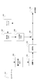
- FIG. 6 is a diagram for describing a procedure for creating a predicted image performed by the encoding device in FIG. 5.
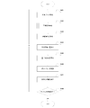
- 6 is a flowchart for explaining an encoding procedure performed by the encoding apparatus of FIG. 5.
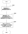
- It is a flowchart for demonstrating the procedure of the prediction image preparation which the encoding apparatus of FIG. 5 performs.
- It is a flowchart for demonstrating the procedure of the decoding which the decoding apparatus of FIG. 6 performs.
- (Encoder) 1 includes an input terminal 101, a block division unit 102, a subtractor 103, an orthogonal transformation unit 104, a quantization unit 105, an inverse quantization unit 106, an inverse transformation unit 107, an adder 108, a frame buffer 109,
- the frequency analysis unit 110, the quantization coefficient encoding unit 111, the output terminal 112, and the predicted image creation unit 113 are configured.
- the input terminal 101 receives the encoding target frame from the outside of the encoding device.
- the block dividing unit 102 receives the encoding target frame from the input terminal 101, and divides the encoding target frame into a plurality of 4 ⁇ 4 pixel rectangular regions. However, the size of the area to be divided may be another size such as 8 ⁇ 8, 16 ⁇ 16, or may not be rectangular.
- the block division unit 102 sends the divided block (hereinafter, encoding target signal) to the subtractor 103.
- the subtracter 103 receives the encoding target signal from the block division unit 102 and also receives the prediction signal from the prediction image creation unit 113. Then, the prediction signal is subtracted from the encoding target signal to generate a residual signal. Then, the generated residual signal is sent to the orthogonal transform unit 104.
- the orthogonal transform unit 104 receives the residual signal from the subtractor 103. Then, a discrete cosine transform (DCT) is performed on the received residual signal to generate a transform coefficient. Then, the generated transform coefficient is sent to the quantization unit 105.
- DCT discrete cosine transform
- the transform performed by the orthogonal transform unit 104 may be another transform (for example, Hadamard transform or discrete sine transform).
- the quantization unit 105 receives the transform coefficient from the orthogonal transform unit 104. Then, the received transform coefficient is quantized to generate a quantized transform coefficient. Then, the quantized transform coefficients are sent to the inverse quantization unit 106 and the quantized coefficient coding unit 111.
- the inverse quantization unit 106 receives the quantized transform coefficient from the quantization unit 105. Then, the quantized transform coefficient is inversely quantized to generate a restored transform coefficient. Then, the restored transform coefficient is sent to the inverse transform unit 107.
- the inverse transform unit 107 receives the restored transform coefficient from the inverse quantization unit 106. Then, inverse DCT is performed on the restored transform coefficient to generate a restored residual signal. Then, the restored residual signal is sent to the adder 108.
- the adder 108 receives the restored residual signal from the inverse transform unit 107 and also receives the prediction signal from the prediction image creation unit 113. Then, a restored signal is generated by adding the prediction signal and the restored residual signal. Then, a restoration signal is sent to the frame buffer 109.
- the frame buffer 109 receives the restoration signal from the adder 108 and stores it at the target position. Also, the reference region of the encoding target block is sent to the frequency analysis unit 110.
- the frequency analysis unit 110 receives the reference signal of the encoding target signal from the frame buffer 109. Then, frequency analysis is performed on the reference signal to extract main components of the reference signal. Then, parameters for creating the main component are sent to the predicted image creation unit 113.
- the main component is a frequency component having a predetermined order or higher.
- the quantization coefficient encoding unit 111 receives the quantized transform coefficient from the quantization unit 105. Then, predetermined entropy encoding is performed on the received quantized transform coefficient to create a bit stream, which is sent to the output terminal 112.
- the output terminal 112 outputs the bit stream to the outside of the encoding device.
- the predicted image creation unit 113 receives parameters for creating the main component of the reference signal from the frequency analysis unit 110. Then, a predicted image of the encoding target block is created using the parameters. The generated predicted image is sent to the subtracter 103.
- the block dividing unit 102 divides the encoding target frame into predetermined regions and creates an encoding target block image (step S401).
- the frequency analysis unit 110 extracts the main component by using the adjacent local decoding region image of the encoding target block from the frame buffer 109 as a reference image. Then, the predicted image creation unit 113 creates a predicted image from the extracted main components (step S402). The predicted image creation procedure will be described later.
- the subtracter 103 subtracts the predicted image from the encoding target block image, thereby creating a residual image (step S403).
- the orthogonal transform unit 104 orthogonally transforms the residual image, and the quantization unit 105 quantizes the coefficient obtained by the orthogonal transform unit 104 to create a quantized transform coefficient (step S404).
- the quantization coefficient encoding unit 111 entropy encodes the quantized transform coefficient to create a quantized transform coefficient bit stream (step S405).
- the inverse quantization unit 106 inversely quantizes the quantized transform coefficient, and the inverse transform unit 107 performs inverse orthogonal transform on the value obtained by the inverse quantization unit 106 to create a decoded residual image (step S406).
- the adder 108 adds the predicted image and the decoded residual image, creates a local decoded image, and stores it in the frame buffer 109 (step S407).
- GMA Generalized harmonic analysis
- x and y are horizontal and vertical positions
- fx and fy are horizontal and vertical frequencies
- phase is a phase
- fx, fy, and phase are arbitrary real numbers. Since it can be expressed in arbitrary fx, fy, and phase, it is possible to perform analysis with higher accuracy than an orthogonal transform method such as DCT generally applied in image coding.
- the frequency analysis unit 110 acquires, from the frame buffer 109, locally decoded images (reference images) of the left, upper, and upper left blocks of the encoding target block (step S301).
- reference numeral 1301 in FIG. 13 is an encoding target block
- reference numeral 1302 is a reference image.
- the reference image is not necessarily limited to the left, upper, and upper left three blocks, and may be only one or two of them, or may be another block such as the upper right. Further, if the right and lower blocks have been decoded, they may be used as reference images. Further, each reference block may not have the same shape as the encoding target block.
- the frequency analysis unit 110 performs a generalized harmonic analysis on the reference image 1302 and extracts one component (step S302).
- the procedure of component extraction is as follows. That is, pattern matching between a signal created by changing fx, fy, and phase and a reference image is repeated, and a signal created by fx, fy, and phase when the mean square error is minimized is used as an extraction component.
- Reference numeral 1304 denotes an extraction component.
- the predicted image creating unit 113 creates a signal of the encoding target block position using fx, fy, and phase of the one extracted component 1304, and sets it as a predicted image 1305 (step S303).
- the predicted image creation procedure of this configuration can be switched adaptively in combination with the conventional predicted image creation procedure.
- efficient encoding cannot be performed by the conventional prediction image creation procedure.
- the prediction method is switched by a switching method using the high frequency component of the encoding target block. .
- (decoder) 2 includes an input terminal 201, a quantized coefficient decoding unit 202, an inverse quantization unit 203, an inverse transform unit 204, an adder 205, a frame buffer 206, a frequency analysis unit 207, an output terminal 208, and a predicted image creation unit. 209.
- the input terminal 201 receives a quantized coefficient bit stream to be decoded from outside the decoding apparatus.
- the quantization coefficient decoding unit 202 receives the quantization coefficient bit stream from the input terminal 201. Then, a predetermined decoding process is performed on the received quantized coefficient bit stream to obtain quantized transform coefficients. Then, the quantized transform coefficient is sent to the inverse quantization unit 203.
- the inverse quantization unit 203 performs a predetermined inverse quantization process on the quantized transform coefficient received from the quantized coefficient decoding unit 202 to obtain a transform coefficient. Then, the transform coefficient is sent to the inverse transform unit 204.
- the inverse transform unit 204 performs a predetermined inverse transform process on the transform coefficient received from the inverse quantization unit 203 to obtain a restored residual signal. Then, the restored residual signal is sent to the adder 205.
- the adder 205 receives the restored residual signal from the inverse transform unit 204, and also receives the prediction signal of the target block from the prediction image creation unit 209. Then, the restored residual signal and the prediction signal are added to create a decoded image of the target block. Then, the generated decoded image is sent to the frame buffer 206 and the output terminal 208.
- the frame buffer 206 receives the decoded image of the target block from the adder 205 and stores it in the target position. Also, the frame buffer 206 sends the reference area of the target block to the frequency analysis unit 207.
- the frequency analysis unit 207 receives the reference signal of the encoding target block from the frame buffer 206. Then, frequency analysis is performed on the reference signal to extract main components of the reference signal. Then, parameters for extracting the main component are sent to the predicted image creation unit 209.
- the output terminal 208 outputs the decoded image to the outside of the decoding device.
- the predicted image creation unit 209 receives parameters for extracting main components of the reference signal from the frequency analysis unit 207. Then, a prediction image of the encoding target block is created using parameters for creating the main component. Then, the generated predicted image is sent to the adder 205.
- the frequency analysis unit 207 uses the adjacent local decoding region image of the block to be encoded from the frame buffer 206 as a reference image, and extracts main components of the reference image. Further, the predicted image creation unit 209 creates a predicted image from the main components of the reference image (step S1101).
- the predicted image creation procedure follows the flowchart of FIG. 3 as in the case of the encoding apparatus.
- the quantized coefficient decoding unit 202 performs a predetermined decoding process on the quantized coefficient bit stream to create a quantized coefficient (step S1102).
- the inverse quantization unit 203 inversely quantizes the quantized coefficient, and the inverse transform unit 204 performs inverse orthogonal transform on the coefficient obtained by the inverse quantization unit 203 to create a decoded residual image (step S1103).
- the adder 205 adds the predicted image and the decoded residual image, creates a local decoded image, and stores it in the frame buffer 206 (step S1104).
- the decoding apparatus repeats the above processing until it reaches the end of the bitstream (step S1105).
- the prediction image creation procedure of the decoding device of this configuration follows FIG. 3 as in the case of the encoding device.
- the frequency analysis unit 110 performs frequency analysis on the adjacent region of the decoding target block to extract main frequency components in the adjacent region, and the predicted image creation unit 113 is extracted. A signal obtained by extending the component is calculated, thereby creating a highly accurate predicted image.
- frequency analysis unit 207 performs the same analysis as frequency analysis unit 110. Therefore, in this embodiment, it is not necessary to send information related to the intra prediction mode. That is, with the configuration of the present embodiment, a highly accurate predicted image can be transmitted with a small amount of information.
- 5 includes an input terminal 501, a block division unit 502, a subtractor 503, an orthogonal transformation unit 504, a quantization unit 505, an inverse quantization unit 506, an inverse transformation unit 507, an adder 508, a frame buffer 509, Frequency analysis unit 510, quantization coefficient encoding unit 511, output terminal 512, reference region buffer 513, prediction image buffer 514, repetition control unit 515, frequency component number encoding unit 516, multiplexing unit 517, prediction image creation unit 519 Consists of.
- the reference region buffer 513, the frequency analysis unit 510, the predicted image creation unit 519, and the predicted image buffer 514 are combined into a multiple frequency analysis unit 518.
- the input terminal 501 receives the encoding target frame from the outside of the encoding device.
- the block dividing unit 502 receives the encoding target frame from the input terminal 501 and divides the encoding target frame into a plurality of 4 ⁇ 4 pixel rectangular areas. However, the size of the area to be divided may be another size such as 8 ⁇ 8, 16 ⁇ 16, or may not be rectangular.
- the block division unit 502 sends the divided block (hereinafter, encoding target signal) to the subtracter 503.
- the subtracter 503 receives the encoding target signal from the block dividing unit 502 and receives the prediction signal from the prediction image buffer 514. Then, the prediction signal is subtracted from the encoding target signal to generate a residual signal. Then, the generated residual signal is sent to the orthogonal transform unit 504.
- the orthogonal transform unit 504 receives the residual signal from the subtracter 503. Then, a discrete cosine transform (DCT) is performed on the received residual signal to generate a transform coefficient. Then, the generated transform coefficient is sent to the quantization unit 505.
- DCT discrete cosine transform
- the calculation performed by the orthogonal transform unit 504 may be another transform (for example, Hadamard transform or discrete sine transform).
- the quantization unit 505 receives the transform coefficient from the orthogonal transform unit 504. Then, the received transform coefficient is quantized to generate a quantized transform coefficient. Then, the quantized transform coefficient is sent to the inverse quantization unit 506 and the quantized coefficient coding unit 511.
- the inverse quantization unit 506 receives the quantized transform coefficient from the quantization unit 505. Then, the quantized transform coefficient is inversely quantized to generate a restored transform coefficient. Then, the restored transform coefficient is sent to the inverse transform unit 507.
- the inverse transform unit 507 receives the restored transform coefficient from the inverse quantization unit 506. Then, inverse DCT is performed on the restored transform coefficient to generate a restored residual signal. Then, the restored residual signal is sent to the adder 508.
- the adder 508 receives the restored residual signal from the inverse transform unit 507 and receives the prediction signal from the prediction image buffer 514. Then, a restored signal is generated by adding the prediction signal and the restored residual signal. Then, the restoration signal is sent to the frame buffer 509.
- the frame buffer 509 receives the restoration signal from the adder 508 and stores it in the target position. Also, the reference area of the encoding target block is sent to the reference area buffer 513.
- the frequency analysis unit 510 receives the reference signal of the encoding target block from the reference area buffer 513. Then, frequency analysis is performed on the reference signal to extract main components. Then, parameters for creating the main component are sent to the predicted image creation unit 519.
- the quantization coefficient encoding unit 511 receives the quantized transform coefficient from the quantization unit 505. Then, predetermined entropy coding is performed on the received quantized transform coefficient, and the resultant is sent to the multiplexing unit 517.
- Output terminal 512 outputs the bit stream to the outside of the encoding device.
- the reference area buffer 513 receives the reference area of the encoding target block from the frame buffer 509 and holds it. Also, the reference area image is sent to the frequency analysis unit 510. Further, the reference region buffer 513 receives the prediction component generated by the prediction image creation unit 519, generates the next reference image by subtracting the prediction component from the held reference image, and holds it again.
- the predicted image buffer 514 creates and holds a predicted signal by adding the predicted components generated by the predicted image creating unit 519 one after another. Then, the generated prediction signal is sent to the subtracter 503.
- the repetition control unit 515 controls the number of components to be analyzed by the frequency analysis unit 510. Then, the number of repetitions (frequency component number) is sent to frequency component number encoding section 516. The repetition control unit 515 ends the repetition when the average square error of each pixel between the original image of the encoding target block and the predicted image stored in the predicted image buffer 514 falls below a predetermined value.
- the evaluation method is not limited to the method using the mean square error, and may be another evaluation method such as a method using the sum of absolute differences.
- the evaluation target signal may be a signal indicating the information amount of the quantized coefficient after encoding or the information amount of the quantized coefficient before encoding.
- the maximum number of repetitions can be set in the repetition control unit 515, or the number of frequency components can be transmitted without setting the number of repetitions as a fixed value.
- the frequency component number encoding unit 516 performs predetermined entropy encoding on the frequency component number received from the repetition control unit 515 and sends the result to the multiplexing unit 517.
- the multiplexing unit 517 performs a predetermined multiplexing process on the quantized coefficient bit stream received from the quantized coefficient encoding unit 511 and the frequency component number bit stream received from the frequency component number encoding unit 516, Create a bitstream of Then, the created bit stream is sent to the output terminal 512.
- the predicted image creation unit 519 receives parameters for creating the main component of the reference signal from the frequency analysis unit 510. Then, a prediction component of the encoding target block is created using the parameters. Then, the generated prediction component is sent to the prediction image buffer 514 and the reference area buffer 513.
- the prediction component creation procedure is the same as that in the embodiment.
- the block dividing unit 502 divides the encoding target frame into predetermined regions and creates an encoding target block image (step S1501).
- the multi-frequency analysis unit 518 uses the adjacent local decoding region image of the block to be encoded from the frame buffer 509 as a reference image, and creates a prediction image (step S1502).
- the predicted image creation procedure will be described later.
- the subtracter 503 creates a residual image by subtracting the predicted image from the encoding target block image (step S1503).
- the orthogonal transform unit 504 performs orthogonal transform on the residual image, and the quantization unit 505 quantizes the coefficient obtained by the orthogonal transform unit 504 to create a quantized transform coefficient (step S1504).
- the quantization coefficient encoding unit 511 entropy encodes the quantized transform coefficient to create a quantized transform coefficient bit stream. Further, the frequency component number encoding unit 516 performs entropy encoding on the frequency component number to create a frequency component number bitstream. Then, the multiplexing unit 517 multiplexes the quantized transform coefficient bit stream and the frequency component number bit stream to create a bit stream (step S1505).
- the inverse quantization unit 506 inversely quantizes the quantized transform coefficient, and the inverse transform unit 507 performs inverse orthogonal transform on the coefficient obtained by the inverse quantization unit 506 to create a decoded residual image (step S1506).
- the adder 508 adds the predicted image and the decoded residual image, creates a local decoded image, and stores it in the frame buffer 509 (step S1507).
- the encoding device performs the above processing for all blocks (step S1508).
- the reference area buffer 513 acquires the locally decoded images (reference images) of the left, upper, and upper left blocks of the encoding target block from the frame buffer 509 (step S1601).
- the reference image is not necessarily limited to the left, upper, and upper left three blocks, and may be only one or two of them, or may be another block such as the upper right. Further, if the right and lower blocks have been decoded, they may be used as reference images. Further, each reference block may not have the same shape as the encoding target block.
- the frequency analysis unit 510 performs a generalized harmonic analysis on the image stored in the reference area buffer 513, and extracts a main component of the reference area. Further, the predicted image creation unit 519 creates a predicted image of the encoding target block using one main component of the reference region created by the frequency analysis unit 510 (step S1602).
- the reference region buffer 513 acquires a component extracted by the frequency analysis unit 510, creates a new reference image by subtracting it from the retained reference region (reference image), and retains it again (step S1603).
- the predicted image buffer 514 acquires a component extracted by the frequency analysis unit 510, adds it to the stored predicted image, creates a new predicted image, and stores it again (step S1604).
- the number of frequency components is incremented (step S1605).
- step S1607 If the number of frequency components is less than the predetermined maximum number of frequency components, the iterative control unit 515 proceeds to step S1607, and if it has reached, the content of the predicted image buffer 514 is set as a predicted image, and the process ends (step S1606). ).
- step S1602 If the average square error between the content of the predicted image buffer 514 and the original image to be encoded is larger than the predetermined error determination value, the process proceeds to step S1602, and the extraction process is continued. Otherwise, the process ends with the content of the predicted image buffer 514 as the predicted image (step S1607).
- a reference numeral 1401 in FIG. 14 indicates a peripheral local decoded image of the encoding target block, and a reference numeral 1402 indicates an encoding target block.
- Reference numeral 1403 indicates a reference area buffer 513, and reference numeral 1404 indicates a predicted image buffer 514.
- Reference numeral 1405 indicates a component extracted by a single frequency analysis process, and reference numeral 1406 indicates a predicted component created by a single frequency analysis process.
- the peripheral local decoded image 1401 of the encoding target block is stored in the reference area buffer 1403 as the first reference image 1407.
- the frequency analysis unit 510 performs frequency analysis on the first reference image 1407, performs component extraction, and creates an analysis result 1409 of the first peripheral region.
- a reference image 1411 for the second time is generated by subtracting the analysis result 1409 of the first peripheral area from the first reference image 1407 stored in the reference area buffer 1403, and the reference area buffer 1403 is updated.
- the predicted image creation unit 519 creates a prediction signal 1410 of the first target block from the analysis result 1409 of the first peripheral region, adds it to the predicted image buffer 1404, and generates a second predicted image 1414.
- the iterative control unit 515 performs end determination, and performs the next extraction if the end condition is not satisfied.
- the frequency analysis unit 510 performs frequency analysis on the second reference image 1411, extracts components, and creates a second peripheral region analysis result 1413.
- the third reference image 1415 is generated by subtracting the second peripheral region analysis result 1413 from the second reference image 1411 stored in the reference region buffer 1403, and the reference region buffer 1403 is updated.
- the predicted image creation unit 519 creates a prediction signal 1414 of the second target block from the analysis result 1413 of the second peripheral region, adds it to the predicted image buffer 1404, and generates a third predicted image 1416.
- the iterative control unit 515 performs end determination, and performs the next extraction if the end condition is not satisfied.
- the encoding apparatus since the multi-frequency analysis unit 518 performs component analysis of adjacent regions a plurality of times, the encoding apparatus according to the first embodiment generates a prediction image for a block having strong components in two or more directions with high accuracy. be able to.
- (decoder) 6 includes an input terminal 601, a syntax analysis unit 602, an inverse quantization unit 603, an inverse transform unit 604, an adder 605, a frame buffer 606, a frequency analysis unit 607, an output terminal 608, a reference region buffer 609, and a prediction.
- the image buffer 610, a repetition control unit 611, a quantization coefficient decoding unit 612, a frequency component number decoding unit 613, and a predicted image creation unit 615 are configured.
- the frequency analysis unit 607, the reference region buffer 609, the predicted image buffer 610, and the predicted image creation unit 615 are combined into a multiple frequency analysis unit 614.
- the input terminal 601 receives a bit stream to be decoded from outside the decoding device.
- the parsing unit 602 receives a bit stream from the input terminal 601. Then, a predetermined parsing process is performed on the received bit stream to obtain a quantized transform coefficient bit stream and a frequency component number bit stream. Then, the quantized transform coefficient bit stream is sent to the quantized coefficient decoding unit 612, and the frequency component number is sent to the frequency component number decoding unit 613.
- the inverse quantization unit 603 performs a predetermined inverse quantization process on the quantized transform coefficient received from the quantized coefficient decoding unit 612 to obtain a transform coefficient. Then, the transform coefficient is sent to the inverse transform unit 604.
- the inverse transform unit 604 performs a predetermined inverse transform process on the transform coefficient received from the inverse quantization unit 603 to obtain a restored residual signal. Then, the restored residual signal is sent to the adder 605.
- the adder 605 receives the restored residual signal from the inverse transform unit 604 and receives the prediction signal of the target block from the prediction image buffer 610. Then, the restored residual signal and the prediction signal are added to create a decoded image of the target block. The generated decoded image is sent to the frame buffer 606 and the output terminal 608.
- the frame buffer 606 receives the decoded image of the target block from the adder 605 and stores it in the target position. Further, the frame buffer 606 sends the reference area of the target block to the reference area buffer 609.
- the frequency analysis unit 607 receives the reference signal of the encoding target block from the reference area buffer 609. Then, frequency analysis is performed on the reference signal to extract main components. Then, parameters for creating the main component are sent to the predicted image creation unit 615.
- the output terminal 608 outputs the decoded image to the outside of the decoding device.
- the reference area buffer 609 receives the reference area of the target block from the frame buffer 606 and holds it. Also, it is sent to the frequency analysis unit 607. Also, the prediction component generated by the prediction image creation unit 615 is received, the prediction component is subtracted from the held reference image, thereby generating the next reference image and holding it again.
- the prediction image buffer 610 generates and holds a prediction signal by adding the prediction components generated by the prediction image creation unit 615 one after another. Then, the generated prediction signal is sent to the adder 605.
- the iterative control unit 611 receives the number of frequency components created by the frequency component number decoding unit 613. Then, the frequency analysis repetition number of the multiple frequency analysis unit 614 is controlled.
- the quantized coefficient decoding unit 612 performs a predetermined decoding process on the quantized coefficient bit stream received from the syntax analysis unit 602 to create a quantized coefficient.
- the generated quantization coefficient is sent to the inverse quantization unit 603.
- the frequency component number decoding unit 613 performs a predetermined decoding process on the frequency analysis component number bit stream received from the syntax analysis unit 602 to create the frequency analysis component number. Then, the generated frequency analysis component number is repeatedly sent to the control unit 611.
- the predicted image creation unit 615 receives parameters for creating the main component of the reference signal from the frequency analysis unit 607. Then, a prediction component of the encoding target block is created using parameters for creating the main component. Then, the generated prediction component is sent to the prediction image buffer 610.
- the prediction component creation procedure is the same as that in the embodiment.
- the multi-frequency analysis unit 614 creates a prediction image using the adjacent local decoding region image of the encoding target block from the frame buffer 606 as a reference image (step S1701).
- the predicted image creation procedure will be described later.
- the parsing unit 602 parses the bit stream and creates a quantization coefficient bit stream and a frequency signal number bit stream.
- the quantization coefficient decoding unit 612 performs a predetermined decoding process on the quantization coefficient bit stream to generate a quantization coefficient
- the frequency component number decoding unit 613 performs a predetermined decoding process on the frequency component number bit stream.
- the number of frequency components is created (step S1702).
- the inverse quantization unit 603 inversely quantizes the quantized transform coefficient, and the inverse transform unit 604 performs inverse orthogonal transform on the coefficient obtained by the inverse quantization unit 603 to create a decoded residual image (step S1703).
- the adder 605 adds the predicted image and the decoded residual image, creates a local decoded image, and stores it in the frame buffer 606 (step S1704).
- the decoding apparatus repeats the above processing until it reaches the end of the bitstream (step S1705).
- the reference area buffer 609 obtains locally decoded images (reference images) of the left, upper, and upper left blocks of the block to be encoded from the frame buffer 606 (step S1201).
- the reference image is not necessarily limited to the left, upper, and upper left three blocks, and may be only one or two of them, or may be another block such as the upper right. Further, if the right and lower blocks have been decoded, they may be used as reference images. Further, each reference block may not have the same shape as the encoding target block.
- the frequency analysis unit 607 performs generalized harmonic analysis on the image stored in the reference area buffer 609 and extracts one component (step S1202).
- the reference area buffer 609 acquires a component extracted by the frequency analysis unit 607, creates a new reference area image by subtracting it from the held reference area, and holds it again (step S1203).
- the predicted image buffer 610 acquires a component extracted by the frequency analysis unit 607, adds it to the stored predicted image, creates a new predicted image, and stores it again (step S1204).
- the number of processed frequency components is incremented (step S1205).
- the repetition control unit 611 proceeds to step S1202 and continues the extraction process. If it has been reached, the content of the predicted image buffer 610 is set as the predicted image, and the process is terminated (step S1206).
- H.264 4 ⁇ 4 mode 0, 701 MPEG-4 AVC / H. H.264 4 ⁇ 4 mode 1, 702 MPEG-4 AVC / H. H.264 4 ⁇ 4 mode 2, 703 MPEG-4 AVC / H. H.264 4 ⁇ 4 mode 3, 704 MPEG-4 AVC / H. H.264 4x4 mode 4, 705 MPEG-4 AVC / H. H.264 4 ⁇ 4 mode 5, 706 MPEG-4 AVC / H. H.264 4x4 mode 6, 707 MPEG-4 AVC / H. H.264 4 ⁇ 4 mode 7, 708 MPEG-4 AVC / H.
- H.264 4 ⁇ 4 mode 8 801 Block that cannot be encoded efficiently by conventional prediction, 802 Block that cannot be encoded efficiently by conventional prediction, 803 Block to be encoded, 804 peripheral image, 1301 block to be encoded, 1302 already decoded Peripheral region, 1303 Frequency analysis result, 1304 Peripheral region analysis result, 1305 Target block prediction signal, 1306 Decoded peripheral region, 1307 Encoding target block, 1308 Target block prediction signal, 1401 Decoded peripheral region, 1402 Encoding Target block, 1403 reference region buffer, 1404 prediction image buffer, 1405 frequency analysis component, 1406 prediction component, 1407 first reference image, 1408 first prediction image 1409 First surrounding area analysis result, 1410 First target block prediction signal, 1411 Second reference image, 1412 Second prediction image, 1413 Second surrounding area analysis result, 1414 Second target block prediction Signal, 1415 3rd reference image, 1416 3rd prediction image.
- the present invention can be used for image coding.
Landscapes
- Engineering & Computer Science (AREA)
- Multimedia (AREA)
- Signal Processing (AREA)
- Compression Or Coding Systems Of Tv Signals (AREA)
Abstract
画像符号化装置は、周波数解析部110と、予測画像作成部113とを有する。周波数解析部110は、符号化対象ブロックの周辺の局所復号済み画像に対し周波数解析を施し、前記局所復号済み画像の所定の次数以上の周波数成分を抽出する。予測画像作成部113は、周波数解析部110によって抽出された周波数成分を符号化対象ブロックに延長して符号化対象ブロックの予測画像を作成する。
Description
本発明は、画面内予測を用いた画像符号化技術に関する。
動画像符号化方式MPEG-4 AVC/H.264では、画面内予測により、画面内符号化効率を向上させている。MPEG-4 AVC/H.264の画面内予測は、符号化対象ブロックの局所復号済み隣接画素を予測のための参照画素とし、参照画素の値を符号化対象ブロックへ外挿することにより、符号化対象ブロックの予測画像を作成する方法である。予測効率を向上させるためには精度の高い予測画像を作成する必要がある。MPEG-4 AVC/H.264では、予め複数の予測モードが用意されており、それらを適応的に切り替えることにより高精度の予測画像を作成する。
図7はMPEG-4 AVC/H.264の4×4画素単位の予測モードを示す図である。符号化対象ブロックの左側と上側の隣接画素を参照画素とし、8方向+平均値モードの計9種の予測モードが示されている。
次に、画面内予測符号化の動作を簡単に説明する。図9は従来の画面内予測符号化装置の構成の一例を示す図である。その構成では、ブロック分割部902が入力端子901に入力された符号化対象フレームを所定の符号化単位に分割し、符号化対象ブロックを作成する。モード判定部915は、符号化対象ブロックを符号化するのに最適と思われる予測モードを決定し、隣接画素外挿部910は、決定された予測モードを元に予測画像を生成する。
減算器903は、符号化対象ブロックの原画像から予測画像を減じ、直交変換部904は、減算器903によって作成された残差信号を直交変換し、量子化部905は、直交変換部904によって得られた係数を量子化して量子化係数を生成する。逆量子化部906は、量子化係数を逆量子化し、逆変換部907は、逆量子化部906によって得られた値を逆直交変換して対象ブロックの局所復号画像を生成する。局所復号画像は、隣接画素外挿部910によって生成された予測画像と加算器908によって足し合わされてフレームバッファ909に蓄積される。
量子化係数符号化部911は、量子化係数をエントロピー符号化し、モード情報符号化部913は、予測モード情報をエントロピー符号化する。多重化部914は、量子化係数符号化部911によって得られた係数と、モード情報符号化部913によって得られた情報とを多重化する。多重化されたデータは、出力端子912から復号装置に伝送される。従来の画面内予測符号化装置は、以上の手順を全てのブロックについて行うことにより、符号化対象フレームを符号化する。
具体的な最適予測モードを決定する方法としては、残差信号の情報量を元に決定する方法、量子化変換係数の情報量を元に決定する方法、及び、符号化量子化変換係数の情報量を元に決定する方法等が存在する。
次に、上記の符号化装置によって生成されたビットストリームを復号する手順について簡単に説明する。図10は従来の画面内予測復号装置の構成の一例を示す図である。その構成では、構文解析部1002が、入力端子1001に入力されたビットストリームを構文解析し、量子化係数復号部1009が量子化係数を復号して量子化変換係数を生成し、モード情報復号部1010が符号化されている予測モード情報を生成する。逆量子化部1003は、量子化変換係数を逆量子化し、逆変換部1004は、逆量子化部1003によって得られた係数を逆直交変換して残差信号を得る。
隣接画素外挿部1007は、フレームバッファ1006から隣接参照画素の値を取得し、予測モード情報を元に、隣接参照画素の値を用いて予測画像を作成する。加算器1005は、隣接画素外挿部1007によって得られた予測画像と、逆変換部1004によって得られた残差信号とを足し合わせて対象ブロックの復号画像を作成する。復号画像は、出力端子1008から装置の外部に出力される。従来の画面内予測復号装置は、以上の手順を全てのブロックについて行うことにより、対象フレームを復号する。
上述したとおり、MPEG-4 AVC/H.264の4×4画素単位で採用されている予測モードは計9種類である。予め用意する予測モード数を増やすことにより、予測精度を高め、残差信号の情報量を削減し、符号化の劣化を抑制することができる。しかしながら、予測モード数の増加は、伝送すべき予測モード情報量の増加を引き起こし、全体の符号化効率向上に直接つながるとは言えない。この問題を解決するために、特許文献1には、多くの予測モードを設けた場合であっても、画面内予測モード情報を効率的に伝送する技術が開示されている。
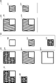
上述したように、MPEG-4 AVC/H.264では、予め用意した複数の画面内予測モードを切り替えることで、画面内符号化効率の向上に繋げている。伝送すべき符号化情報は、量子化変換係数と、予測モード情報である。符号化対象ブロックが図7に示す矢印の方向に強い成分を有する場合は予測精度が高くなることが期待され、効率的な符号化が可能である。しかしながら、例えば符号化対象ブロックが図8の符号801で示すような信号分布であった場合、最も効率的に符号化できると思われるモード700かモード707(図7参照)を採用しても、強い成分を除去しきれず、大きな残差成分が残る。取り切れない残差成分は高周波数成分であり、符号化効率の低下と、信号の劣化を引き起こす。
予測モードの種類を増やすことにより、この問題は回避できるが、予測モード数の増加は、伝送すべきモード情報の量を増加させることになるため、かえって符号化効率を低下させる原因になる。特許文献1には、予測モード数を増やしても予測モード情報の量を効率的に抑圧する技術が開示されているが、入力信号は無数に存在し、予測モード数の増加は画面内予測効率を向上させるための本質的な改善策とはなり得ない。
また、MPEG-4 AVC/H.264のような外挿予測では、図8の符号803のように複数方向に強い成分が存在するブロックにおいても、一方向の成分しか予測できないため、高精度に予測することができず、やはり画面内予測の効率を低下させる原因となっている。
本発明は、少ない情報量で画面内予測符号化を効率良く実行する画像符号化装置及び画像符号化方法を提供することを目的とする。また、本発明は、本発明の画像符号化装置及び画像符号化方法によって符号化された画像信号を復号する画像復号装置及び画像復号方法を提供することを目的とする。
上記課題を解決し上記目的を達成するために、本発明の画像符号化装置は、符号化対象ブロックの周辺の局所復号済み画像に対し周波数解析を施し、前記局所復号済み画像の所定の次数以上の周波数成分を抽出する周波数解析部と、前記周波数解析部によって抽出された周波数成分を前記符号化対象ブロックに延長して前記符号化対象ブロックの予測画像を作成する予測画像作成部とを有する。
本発明の画像符号化装置は、更に、前記局所復号済み画像から前記周波数解析部によって抽出された周波数成分を減じて第1保持部に格納する第1格納部と、前記第1保持部によって保持されている信号に、前記周波数解析部によって抽出された周波数成分から作成された予測信号を加算して第2保持部に格納する第2格納部と、前記周波数解析部が抽出する信号数を制御する抽出繰り返し制御部とを有してもよい。また、前記周波数解析は、例えば、一般化調和解析である。
また、本発明の画像符号化方法は、符号化対象ブロックの周辺の局所復号済み画像に対し周波数解析を施し、前記局所復号済み画像の所定の次数以上の周波数成分を抽出するステップと、抽出した周波数成分を前記符号化対象ブロックに延長して前記符号化対象ブロックの予測画像を作成するステップとを含む。
本発明の画像符号化方法は、更に、前記局所復号済み画像から抽出した周波数成分を減じて第1保持部に格納するステップと、前記第1保持部において保持されている信号に、前記周波数成分を抽出するステップにおいて抽出した周波数成分から作成された予測信号を加算して第2保持部に格納するステップと、前記周波数成分を抽出するステップにおいて抽出する信号数を制御するステップとを含んでもよい。また、前記周波数解析は、例えば、一般化調和解析である。
また、本発明の画像復号装置は、復号対象ブロックの周辺の局所復号済み画像に対し周波数解析を施し、前記局所復号済み画像の所定の次数以上の周波数成分を抽出する周波数解析部と、前記周波数解析部によって抽出された周波数成分を前記復号対象ブロックに延長して前記復号対象ブロックの予測画像を作成する予測画像作成部とを有する。
本発明の画像復号装置は、更に、前記局所復号済み画像から前記周波数解析部によって抽出された周波数成分を減じて第1保持部に格納する第1格納部と、前記第1保持部によって保持されている信号に、前記周波数解析部によって抽出された周波数成分から作成された予測信号を加算して第2保持部に格納する第2格納部と、前記周波数解析部が抽出する信号数を制御する抽出繰り返し制御部とを有してもよい。また、前記周波数解析は、例えば、一般化調和解析である。
また、本発明の画像復号方法は、復号対象ブロックの周辺の局所復号済み画像に対し周波数解析を施し、前記局所復号済み画像の所定の次数以上の周波数成分を抽出するステップと、抽出した周波数成分を前記復号対象ブロックに延長して前記復号対象ブロックの予測画像を作成するステップとを含む。
本発明の画像復号方法は、更に、前記局所復号済み画像から抽出した周波数成分を減じて第1保持部に格納するステップと、前記第1保持部において保持されている信号に、前記周波数成分を抽出するステップにおいて抽出した周波数成分から作成された予測信号を加算して第2保持部に格納するステップと、前記周波数成分を抽出するステップにおいて抽出する信号数を制御するステップとを含んでもよい。前記周波数解析は、例えば、一般化調和解析である。
本発明は、少ない情報量で画面内予測符号化を効率良く実行する画像符号化装置及び画像符号化方法を提供することができる。また、本発明は、本発明の画像符号化装置及び画像符号化方法によって符号化された画像信号を復号する画像復号装置及び画像復号方法を提供することができる。
すなわち、本発明の画像符号化装置及び画像符号化方法により、符号化対象ブロックの信号形状によらず、高精度な予測画像を作成することできる、また、本発明の画像復号装置及び画像復号方法では、復号対象ブロックの周辺の局所復号済み画像に対し周波数解析を施すので、本発明の画像符号化装置及び画像符号化方法により得られる情報の量を従来より削減することができる。よって、本発明は、画面内予測符号化の効率を向上させることができる。
以下に、本発明を実施するための形態を図面を参照して説明する。
(エンコーダ)
図1の符号化装置は、入力端子101、ブロック分割部102、減算器103、直交変換部104、量子化部105、逆量子化部106、逆変換部107、加算器108、フレームバッファ109、周波数解析部110、量子化係数符号化部111、出力端子112、予測画像作成部113により構成されている。
図1の符号化装置は、入力端子101、ブロック分割部102、減算器103、直交変換部104、量子化部105、逆量子化部106、逆変換部107、加算器108、フレームバッファ109、周波数解析部110、量子化係数符号化部111、出力端子112、予測画像作成部113により構成されている。
入力端子101は、符号化装置の外部から符号化対象フレームを受け取る。
ブロック分割部102は、入力端子101から符号化対象フレームを受け取り、符号化対象フレームを複数の4×4画素の矩形領域に分割する。ただし、分割する領域の大きさは、8×8、16×16等、別のサイズであっても構わないし、更に矩形形状でなくとも構わない。ブロック分割部102は、分割したブロック(以下、符号化対象信号)を減算器103へ送る。
減算器103は、ブロック分割部102から符号化対象信号を受け取り、また、予測画像作成部113から予測信号を受け取る。そして、符号化対象信号から予測信号を減じ、残差信号を生成する。そして、生成した残差信号を直交変換部104へ送る。
直交変換部104は、減算器103から残差信号を受け取る。そして、受け取った残差信号に対し、離散コサイン変換(DCT)を施し、変換係数を生成する。そして、生成した変換係数を量子化部105へ送る。ただし、直交変換部104が行う変換は別の変換(例えば、アダマール変換、離散サイン変換)であっても構わない。
量子化部105は、直交変換部104から変換係数を受け取る。そして、受け取った変換係数を量子化して量子化変換係数を生成する。そして、量子化変換係数を逆量子化部106と量子化係数符号化部111へ送る。
逆量子化部106は、量子化部105から量子化変換係数を受け取る。そして、量子化変換係数を逆量子化して復元変換係数を生成する。そして、復元変換係数を逆変換部107へ送る。
逆変換部107は、逆量子化部106から復元変換係数を受け取る。そして、復元変換係数に対し、逆DCTを施し、復元残差信号を生成する。そして、復元残差信号を加算器108へ送る。
加算器108は、逆変換部107から復元残差信号を受け取り、また、予測画像作成部113から予測信号を受け取る。そして、予測信号と復元残差信号を足し合わせることにより、復元信号を生成する。そして、復元信号をフレームバッファ109へ送る。
フレームバッファ109は、加算器108から復元信号を受け取り、対象位置に格納する。また、符号化対象ブロックの参照領域を周波数解析部110へ送る。
周波数解析部110は、フレームバッファ109から符号化対象信号の参照信号を受け取る。そして、参照信号に対し周波数解析を施し、参照信号の主要成分を抽出する。そして、主要成分を作成するためのパラメータを予測画像作成部113へ送る。なお、主要成分は、所定の次数以上の周波数成分である。
量子化係数符号化部111は、量子化部105から量子化変換係数を受け取る。そして、受け取った量子化変換係数に対し所定のエントロピー符号化を施し、ビットストリームを作成し、出力端子112へ送る。
出力端子112は、ビットストリームを符号化装置の外部へ出力する。
予測画像作成部113は、周波数解析部110から参照信号の主要成分を作成するためのパラメータを受け取る。そしてそのパラメータを用いて符号化対象ブロックの予測画像を作成する。そして作成した予測画像を減算器103へ送る。
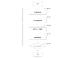
ここで、本構成の符号化装置で1フレームの画像を符号化する手順を図4のフローチャートを用いて説明する。
ブロック分割部102は、符号化対象フレームを所定の領域に分割し、符号化対象ブロック画像を作成する(ステップS401)。
周波数解析部110は、フレームバッファ109からの符号化対象ブロックの隣接局所復号領域画像を参照画像とし、主要成分を抽出する。そして、予測画像作成部113は、抽出された主要成分から予測画像を作成する(ステップS402)。予測画像作成手順については後述する。
減算器103は、符号化対象ブロック画像から予測画像を減じ、それにより、残差画像を作成する(ステップS403)。
直交変換部104は、残差画像を直交変換し、量子化部105は、直交変換部104によって得られた係数を量子化して量子化変換係数を作成する(ステップS404)。
量子化係数符号化部111は、量子化変換係数をエントロピー符号化し、量子化変換係数ビットストリームを作成する(ステップS405)。
逆量子化部106は、量子化変換係数を逆量子化し、逆変換部107は、逆量子化部106によって得られた値を逆直交変換して復号残差画像を作成する(ステップS406)。
加算器108は、予測画像と復号残差画像を足し合わせ、局所復号画像を作成し、フレームバッファ109に格納する(ステップS407)。
以上の処理が全てのブロックに対して行われる(ステップS408)。
ここで、本構成の周波数解析を用いた予測画像生成処理について説明する。本構成の周波数解析として、一般化調和解析(GHA)を適用する。一般化調和解析は、解析対象信号を
signal(x、y)=∫fx,fy,phasesin(2π(fx・x+fy・y+phase))
で表す解析手法である。ただし、x、yはそれぞれ水平方向、垂直方向の位置、fx、fyはそれぞれ水平方向、垂直方向の周波数、phaseは位相である。fx、fy、phaseは任意の実数である。任意のfx,fy,phaseで表現することができるため、一般に画像符号化で適用されるDCT等の直交変換方式に比べ、精度の高い解析が可能である。
signal(x、y)=∫fx,fy,phasesin(2π(fx・x+fy・y+phase))
で表す解析手法である。ただし、x、yはそれぞれ水平方向、垂直方向の位置、fx、fyはそれぞれ水平方向、垂直方向の周波数、phaseは位相である。fx、fy、phaseは任意の実数である。任意のfx,fy,phaseで表現することができるため、一般に画像符号化で適用されるDCT等の直交変換方式に比べ、精度の高い解析が可能である。
次に、図3のフローチャートを用いて、本構成の予測画像作成手順について説明する。
周波数解析部110は、フレームバッファ109から、符号化対象ブロックの左、上、左上のブロックの局所復号画像(参照画像)を取得する(ステップS301)。例えば、図13の符号1301が符号化対象ブロックであり、符号1302が参照画像である。ただし、参照画像は、必ずしも左、上、左上の3ブロックに限定するものではなく、そのうちの1つ、又は2つのみでもよいし、右上等他のブロックであってもよい。また、右、下側ブロックが復号済みであればそれを参照画像として用いてもよい。更に、各参照ブロックは符号化対象ブロックと同一形状でなくてもよい。
周波数解析部110は、参照画像1302に対し一般化調和解析を行い、一成分を抽出する(ステップS302)。成分抽出の手順は次の通りである。すなわち、fx、fy、phaseを変動させ作成した信号と、参照画像と、のパターンマッチングを繰り返し、平均平方誤差が最小となるときのfx、fy、phaseにより作成される信号を抽出成分とする。1304が抽出成分である。
更に予測画像作成部113は、一抽出成分1304のfx、fy、phaseを用いて、符号化対象ブロック位置の信号を作成し、予測画像1305とする(ステップS303)。予測画像1305は、次のようにして作成される。すなわち、ステップS302で作成した参照画像の抽出成分1304を、対象ブロックの位置まで延長させた信号とし、ステップS302で求めたfx、fy、phaseと、符号化対象ブロック内画素位置x、yを用いて、
pred(x、y)=sin(2π(fx・(x+refX)+fy・(y+refY)+phase)
により、予測画像1305を作成する。
pred(x、y)=sin(2π(fx・(x+refX)+fy・(y+refY)+phase)
により、予測画像1305を作成する。
更に予測画像の作成の一例として、符号化対象画像が符号1307であって、参照画像が符号1306である場合のように、上方向の領域のみを参照する場合、
pred(x、y)=sin(2π(fx・x+fy・(y+refY)+phase)
により、予測画像1308を作成する。
pred(x、y)=sin(2π(fx・x+fy・(y+refY)+phase)
により、予測画像1308を作成する。
また、本構成の予測画像作成手順は、従来の予測画像作成手順と併用し、適応的に切り替えることが可能である。符号化対象ブロックがエッジ成分を多く含むような場合、従来の予測画像作成手順では効率的な符号化ができないため、例えば、符号化対象ブロックの高周波数成分を用いた切り替える方法により予測方法を切り替える。
(デコーダ)
図2の復号装置は、入力端子201、量子化係数復号部202、逆量子化部203、逆変換部204、加算器205、フレームバッファ206、周波数解析部207、出力端子208、予測画像作成部209により構成される。
図2の復号装置は、入力端子201、量子化係数復号部202、逆量子化部203、逆変換部204、加算器205、フレームバッファ206、周波数解析部207、出力端子208、予測画像作成部209により構成される。
入力端子201は、復号装置の外部から復号すべき量子化係数ビットストリームを受け取る。
量子化係数復号部202は、入力端子201から、量子化係数ビットストリームを受け取る。そして、受け取った量子化係数ビットストリームに対して所定の復号処理を行い、量子化変換係数を得る。そして、量子化変換係数を逆量子化部203へ送る。
逆量子化部203は、量子化係数復号部202から受け取った量子化変換係数に対し所定の逆量子化処理を行い、変換係数を得る。そして変換係数を逆変換部204へ送る。
逆変換部204は、逆量子化部203から受け取った変換係数に対し所定の逆変換処理を行い、復元残差信号を得る。そして復元残差信号を加算器205へ送る。
加算器205は、逆変換部204から復元残差信号を受け取り、また、予測画像作成部209から、対象ブロックの予測信号を受け取る。そして、復元残差信号と予測信号を足し合わせ、対象ブロックの復号画像を作成する。そして、作成した復号画像をフレームバッファ206と、出力端子208へ送る。
フレームバッファ206は、加算器205から対象ブロックの復号画像を受け取り、対象位置に格納する。また、フレームバッファ206は、対象ブロックの参照領域を周波数解析部207へ送る。
周波数解析部207は、フレームバッファ206から符号化対象ブロックの参照信号を受け取る。そして、参照信号に対し周波数解析を施し、参照信号の主要成分を抽出する。そして、主要成分を抽出するためのパラメータを予測画像作成部209へ送る。
出力端子208は、復号画像を復号装置の外部へ出力する。
予測画像作成部209は、周波数解析部207から参照信号の主要成分を抽出するためのパラメータを受け取る。そして主要成分を作成するためのパラメータを用いて符号化対象ブロックの予測画像を作成する。そして作成した予測画像を加算器205へ送る。
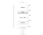
次に、本構成の復号装置で1フレームの画像を復号する手順を図11のフローチャートを用いて説明する。
周波数解析部207は、フレームバッファ206からの符号化対象ブロックの隣接局所復号領域画像を参照画像とし、参照画像の主要成分を抽出する。更に予測画像作成部209は、参照画像の主要成分から予測画像を作成する(ステップS1101)。予測画像作成手順は符号化装置と同様、図3のフローチャートに従う。
量子化係数復号部202は、量子化係数ビットストリームに対し所定の復号処理を行い、量子化係数を作成する(ステップS1102)。
逆量子化部203は、量子化係数を逆量子化し、逆変換部204は、逆量子化部203によって得られた係数を逆直交変換して復号残差画像を作成する(ステップS1103)。
加算器205は、予測画像と復号残差画像を足し合わせ、局所復号画像を作成し、フレームバッファ206に格納する(ステップS1104)。
復号装置は、以上の処理をビットストリームの終端に行きつくまで繰り返す(ステップS1105)。
本構成の復号装置の予測画像作成手順は、符号化装置と同様、図3に従う。
上述したように、本実施の形態の符号化装置では、周波数解析部110が復号対象ブロックの隣接領域を周波数解析して隣接領域の主要な周波数成分を抽出し、予測画像作成部113が抽出された成分を延長した信号を算出し、それにより高精度な予測画像を作成する。本実施の形態の復号装置では、周波数解析部207が周波数解析部110と同様の解析を行う。そのため、本実施の形態では、画面内予測モードに関する情報を送らずに済む。つまり、本実施の形態の構成により、少ない情報量で高精度な予測画像を伝送することができる。
図5の符号化装置は、入力端子501、ブロック分割部502、減算器503、直交変換部504、量子化部505、逆量子化部506、逆変換部507、加算器508、フレームバッファ509、周波数解析部510、量子化係数符号化部511、出力端子512、参照領域バッファ513、予測画像バッファ514、繰り返し制御部515、周波数成分数符号化部516、多重化部517、予測画像作成部519により構成される。参照領域バッファ513と周波数解析部510と予測画像作成部519と予測画像バッファ514を合わせて多重周波数解析部518とする。
入力端子501は、符号化装置の外部から符号化対象フレームを受け取る。
ブロック分割部502は、入力端子501から符号化対象フレームを受け取り、符号化対象フレームを複数の4×4画素の矩形領域に分割する。ただし、分割する領域の大きさは、8×8、16×16等、別のサイズであっても構わないし、更に矩形形状でなくとも構わない。ブロック分割部502は、分割したブロック(以下、符号化対象信号)を減算器503へ送る。
減算器503は、ブロック分割部502から符号化対象信号を受け取り、予測画像バッファ514から予測信号を受け取る。そして、符号化対象信号から予測信号を減じ、残差信号を生成する。そして、生成した残差信号を直交変換部504へ送る。
直交変換部504は、減算器503から残差信号を受け取る。そして、受け取った残差信号に対し、離散コサイン変換(DCT)を施し、変換係数を生成する。そして、生成した変換係数を量子化部505へ送る。ただし、直交変換部504が行う演算は別の変換(例えば、アダマール変換、離散サイン変換)であっても構わない。
量子化部505は、直交変換部504から変換係数を受け取る。そして、受け取った変換係数を量子化して量子化変換係数を生成する。そして、量子化変換係数を逆量子化部506と量子化係数符号化部511へ送る。
逆量子化部506は、量子化部505から量子化変換係数を受け取る。そして、量子化変換係数を逆量子化して復元変換係数を生成する。そして、復元変換係数を逆変換部507へ送る。
逆変換部507は、逆量子化部506から復元変換係数を受け取る。そして、復元変換係数に対し、逆DCTを施し、復元残差信号を生成する。そして、復元残差信号を加算器508へ送る。
加算器508は、逆変換部507から復元残差信号を受け取り、予測画像バッファ514から予測信号を受け取る。そして、予測信号と復元残差信号を足し合わせることにより、復元信号を生成する。そして、復元信号をフレームバッファ509へ送る。
フレームバッファ509は、加算器508から復元信号を受け取り、対象位置に格納する。また、符号化対象ブロックの参照領域を参照領域バッファ513へ送る。
周波数解析部510は、参照領域バッファ513から符号化対象ブロックの参照信号を受け取る。そして、参照信号に対し周波数解析を施し、主要成分を抽出する。そして、主要成分を作成するためのパラメータを、予測画像作成部519へ送る。
量子化係数符号化部511は、量子化部505から量子化変換係数を受け取る。そして、受け取った量子化変換係数に対し所定のエントロピー符号化を施し、多重化部517へ送る。
出力端子512は、ビットストリームを符号化装置の外部へ出力する。
参照領域バッファ513は、フレームバッファ509から符号化対象ブロックの参照領域を受け取り、保持する。また、参照領域画像を周波数解析部510へ送る。また、参照領域バッファ513は、予測画像作成部519によって生成された予測成分を受け取り、保持している参照画像から予測成分を減ずることにより、次の参照画像を生成し、改めて保持する。
予測画像バッファ514は、予測画像作成部519によって生成された予測成分を次々に足し合わせることにより、予測信号を作成し、保持する。そして、作成した予測信号を減算器503へ送る。
繰り返し制御部515は、周波数解析部510で解析する成分の数を制御する。そして、繰り返し数(周波数成分数)を、周波数成分数符号化部516へ送る。繰り返し制御部515は、符号化対象ブロックの原画像と予測画像バッファ514に格納された予測画像との各画素の平均平方誤差が所定の値を下回ったときに繰り返しを終了する。ただし、評価方法は、平均平方誤差を用いる方法に限定されず、差分絶対値和を用いる方法等、別の評価手法であってもかまわない。また、評価対象信号は、符号化後の量子化係数の情報量や符号化前の量子化係数の情報量を示す信号であってもかまわない。また、繰り返し制御部515に、繰り返しの最大値を設定することもできるし、繰り返し数を固定値として、周波数成分数を伝送しないこともできる。
周波数成分数符号化部516は、繰り返し制御部515から受け取った周波数成分数に対し、所定のエントロピー符号化を施し、多重化部517へ送る。
多重化部517は、量子化係数符号化部511から受け取った量子化係数ビットストリームと、周波数成分数符号化部516から受け取った周波数成分数ビットストリームに対し所定の多重化処理を施し、一本のビットストリームを作成する。そして作成したビットストリームを出力端子512へ送る。
予測画像作成部519は、周波数解析部510から参照信号の主要成分を作成するためのパラメータを受け取る。そしてそのパラメータを用いて符号化対象ブロックの予測成分を作成する。そして作成した予測成分を、予測画像バッファ514と、参照領域バッファ513へ送る。予測成分作成手順は実施の形態と同じである。
次に、本構成の符号化装置で1フレームの画像を符号化する手順を図15のフローチャートを用いて説明する。
ブロック分割部502は、符号化対象フレームを所定の領域に分割し、符号化対象ブロック画像を作成する(ステップS1501)。
多重周波数解析部518は、フレームバッファ509からの符号化対象ブロックの隣接局所復号領域画像を参照画像とし、予測画像を作成する(ステップS1502)。予測画像作成手順については後述する。
減算器503は、符号化対象ブロック画像から予測画像を減ずることにより、残差画像を作成する(ステップS1503)。
直交変換部504は、残差画像を直交変換し、量子化部505は、直交変換部504によって得られた係数を量子化して量子化変換係数を作成する(ステップS1504)。
量子化係数符号化部511は、量子化変換係数をエントロピー符号化し、量子化変換係数ビットストリームを作成する。また、周波数成分数符号化部516は、周波数成分数をエントロピー符号化し、周波数成分数ビットストリームを作成する。そして、多重化部517は、量子化変換係数ビットストリームと周波数成分数ビットストリームを多重化しビットストリームを作成する(ステップS1505)。
逆量子化部506は、量子化変換係数を逆量子化し、逆変換部507は、逆量子化部506によって得られた係数を逆直交変換して復号残差画像を作成する(ステップS1506)。
加算器508は、予測画像と復号残差画像を足し合わせ、局所復号画像を作成し、フレームバッファ509に格納する(ステップS1507)。
符号化装置は、以上の処理を全てのブロックに対し行う(ステップS1508)。
次に、本構成の詳細な予測画像作成手順について図16のフローチャートを用いて説明する。
参照領域バッファ513は、フレームバッファ509から符号化対象ブロックの左、上、左上のブロックの局所復号画像(参照画像)を取得する(ステップS1601)。ただし、参照画像は、必ずしも左、上、左上の3ブロックに限定するものではなく、そのうちの1つ、又は2つのみでもよいし、右上等他のブロックであってもよい。また、右、下側ブロックが復号済みであればそれを参照画像として用いてもよい。更に、各参照ブロックは符号化対象ブロックと同一形状でなくてもよい。
周波数解析部510は、参照領域バッファ513に格納された画像に対し一般化調和解析を行い、参照領域の主要な一成分を抽出する。更に予測画像作成部519は、周波数解析部510によって作成された参照領域の主要な一成分を用いて、符号化対象ブロックの予測画像を作成する(ステップS1602)。
参照領域バッファ513は、周波数解析部510によって抽出された成分を取得し、保持している参照領域(参照画像)から減ずることにより、新たな参照画像を作成し、改めて保持する(ステップS1603)。
予測画像バッファ514は、周波数解析部510によって抽出された成分を取得し、保持している予測画像に足すことにより、新たな予測画像を作成し、改めて保持する(ステップS1604)。
周波数成分数をインクリメントする(ステップS1605)。
繰り返し制御部515は、周波数成分数が所定の周波数成分数最大値に満たない場合はステップS1607へ進み、達していた場合は予測画像バッファ514の内容を予測画像として、処理を終了する(ステップS1606)。
予測画像バッファ514の内容と符号化対象原画像との平均平方誤差が所定の誤差判定値より大きい場合、ステップS1602へ進み、抽出処理を継続する。そうでない場合、予測画像バッファ514の内容を予測画像として、処理を終了する(ステップS1607)。
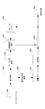
更に予測画像作成手順の一例を、図14を用いて説明する。図14の符号1401は、符号化対象ブロックの周辺局所復号画像を示しており、符号1402は、符号化対象ブロックを示している。符号1403は、参照領域バッファ513を示しており、符号1404は、予測画像バッファ514を示している。また、符号1405は、一回の周波数解析処理で抽出した成分を示しており、符号1406は、一回の周波数解析処理で作成した予測成分を示している。
まず、符号化対象ブロックの周辺局所復号画像1401が最初の参照画像1407として参照領域バッファ1403に格納される。
最初の参照画像1407に対し、周波数解析部510は、周波数解析を行い、成分抽出を行い、最初の周辺領域の解析結果1409を作成する。参照領域バッファ1403に格納された最初の参照画像1407から最初の周辺領域の解析結果1409を減ずることにより2回目の参照画像1411を生成し、参照領域バッファ1403を更新する。また予測画像作成部519は、最初の周辺領域の解析結果1409から最初の対象ブロックの予測信号1410を作成し、予測画像バッファ1404に足しこみ、2回目の予測画像1414を生成する。ここで、繰り返し制御部515は、終了判定を行い、終了条件を満たさなければ次の抽出を行う。
2回目の参照画像1411に対し、周波数解析部510は、周波数解析を行い、成分抽出を行い、2回目の周辺領域の解析結果1413を作成する。参照領域バッファ1403に格納された2回目の参照画像1411から2回目の周辺領域の解析結果1413を減ずることにより3回目の参照画像1415を生成し、参照領域バッファ1403を更新する。また予測画像作成部519は、2回目の周辺領域の解析結果1413から2回目の対象ブロックの予測信号1414を作成し、予測画像バッファ1404に足しこみ、3回目の予測画像1416を生成する。ここで、繰り返し制御部515は、終了判定を行い、終了条件を満たさなければ次の抽出を行う。
以下同様の処理が繰り返され、終了時の予測画像バッファ1404の3回目の予測画像1416を予測画像として予測画像作成処理は終了する。
上述したように、多重周波数解析部518が隣接領域の成分解析を複数回行うので、実施例1の符号化装置は、2方向以上の強い成分が存在するブロックに対する予測画像を高精度で生成することができる。
(デコーダ)
図6の復号装置は、入力端子601、構文解析部602、逆量子化部603、逆変換部604、加算器605、フレームバッファ606、周波数解析部607、出力端子608、参照領域バッファ609、予測画像バッファ610、繰り返し制御部611、量子化係数復号部612、周波数成分数復号部613、予測画像作成部615により構成される。周波数解析部607、参照領域バッファ609、予測画像バッファ610、予測画像作成部615を合わせて多重周波数解析部614とする。
図6の復号装置は、入力端子601、構文解析部602、逆量子化部603、逆変換部604、加算器605、フレームバッファ606、周波数解析部607、出力端子608、参照領域バッファ609、予測画像バッファ610、繰り返し制御部611、量子化係数復号部612、周波数成分数復号部613、予測画像作成部615により構成される。周波数解析部607、参照領域バッファ609、予測画像バッファ610、予測画像作成部615を合わせて多重周波数解析部614とする。
入力端子601は、復号装置の外部から復号すべきビットストリームを受け取る。
構文解析部602は、入力端子601から、ビットストリームを受け取る。そして、受け取ったビットストリームに対して所定の構文解析処理を行い、量子化変換係数ビットストリームと周波数成分数ビットストリームを得る。そして、量子化変換係数ビットストリームを量子化係数復号部612へ送り、周波数成分数を周波数成分数復号部613へ送る。
逆量子化部603は、量子化係数復号部612から受け取った量子化変換係数に対し所定の逆量子化処理を行い、変換係数を得る。そして変換係数を逆変換部604へ送る。
逆変換部604は、逆量子化部603から受け取った変換係数に対し所定の逆変換処理を行い、復元残差信号を得る。そして復元残差信号を加算器605へ送る。
加算器605は、逆変換部604から復元残差信号を受け取り、予測画像バッファ610から対象ブロックの予測信号を受け取る。そして、復元残差信号と予測信号を足し合わせ、対象ブロックの復号画像を作成する。そして、作成した復号画像をフレームバッファ606と、出力端子608へ送る。
フレームバッファ606は、加算器605から対象ブロックの復号画像を受け取り、対象位置に格納する。また、フレームバッファ606は、対象ブロックの参照領域を参照領域バッファ609へ送る。
周波数解析部607は、参照領域バッファ609から符号化対象ブロックの参照信号を受け取る。そして、参照信号に対し周波数解析を施し、主要成分を抽出する。そして、主要成分を作成するためのパラメータを、予測画像作成部615へ送る。
出力端子608は、復号画像を復号装置の外部へ出力する。
参照領域バッファ609は、フレームバッファ606から対象ブロックの参照領域を受け取り、保持する。また、周波数解析部607へ送る。また、予測画像作成部615によって生成された予測成分を受け取り、保持している参照画像から予測成分を減じ、それにより、次の参照画像を生成し、改めて保持する。
予測画像バッファ610は、予測画像作成部615によって生成された予測成分を次々に足し合わせることにより、予測信号を生成し、保持する。そして、生成した予測信号を加算器605へ送る。
繰り返し制御部611は、周波数成分数復号部613によって作成された周波数成分数を受け取る。そして、多重周波数解析部614の周波数解析繰り返し数を制御する。
量子化係数復号部612は、構文解析部602から受け取った量子化係数ビットストリームに対し所定の復号処理を行い、量子化係数を作成する。そして作成した量子化係数を逆量子化部603へ送る。
周波数成分数復号部613は、構文解析部602から受け取った周波数解析成分数ビットストリームに対し所定の復号処理を行い、周波数解析成分数を作成する。そして作成した周波数解析成分数を繰り返し制御部611へ送る。
予測画像作成部615は、周波数解析部607から参照信号の主要成分を作成するためのパラメータを受け取る。そして主要成分を作成するためのパラメータを用いて符号化対象ブロックの予測成分を作成する。そして作成した予測成分を、予測画像バッファ610へ送る。予測成分作成手順は実施の形態と同じである。
次に、本構成の復号装置で1フレームの画像を復号する手順を図17のフローチャートを用いて説明する。
多重周波数解析部614は、フレームバッファ606からの符号化対象ブロックの隣接局所復号領域画像を参照画像とし、予測画像を作成する(ステップS1701)。予測画像作成手順は後述する。
構文解析部602は、ビットストリームを構文解析し、量子化係数ビットストリームと周波数信号数ビットストリームを作成する。量子化係数復号部612は、量子化係数ビットストリームに対し所定の復号処理を行い、量子化係数を作成し、周波数成分数復号部613は、周波数成分数ビットストリームに対し所定の復号処理を行い、周波数成分数を作成する(ステップS1702)。
逆量子化部603は、量子化変換係数を逆量子化し、逆変換部604は、逆量子化部603によって得られた係数を逆直交変換し、復号残差画像を作成する(ステップS1703)。
加算器605は、予測画像と復号残差画像を足し合わせ、局所復号画像を作成し、フレームバッファ606に格納する(ステップS1704)。
復号装置は、以上の処理をビットストリームの終端に行きつくまで繰り返す(ステップS1705)。
次に、本構成の詳細な予測画像作成手順について図12のフローチャートを用いて説明する。
参照領域バッファ609は、フレームバッファ606から符号化対象ブロックの左、上、左上のブロックの局所復号画像(参照画像)を取得する(ステップS1201)。ただし、参照画像は、必ずしも左、上、左上の3ブロックに限定するものではなく、そのうちの1つ、又は2つのみでもよいし、右上等他のブロックであってもよい。また、右、下側ブロックが復号済みであればそれを参照画像として用いてもよい。更に、各参照ブロックは符号化対象ブロックと同一形状でなくてもよい。
周波数解析部607は、参照領域バッファ609に格納された画像に対し一般化調和解析を行い、一成分を抽出する(ステップS1202)。
参照領域バッファ609は、周波数解析部607によって抽出された成分を取得し、保持している参照領域から減ずることにより、新たな参照領域画像を作成し、改めて保持する(ステップS1203)。
予測画像バッファ610は、周波数解析部607によって抽出された成分を取得し、保持している予測画像に足すことにより、新たな予測画像を作成し、改めて保持する(ステップS1204)。
処理済み周波数成分数をインクリメントする(ステップS1205)。
繰り返し制御部611は、処理済み周波数成分数が所定の周波数成分数に満たない場合はステップS1202へ進み、抽出処理を継続する。達していた場合は予測画像バッファ610の内容を予測画像として、処理を終了する(ステップS1206)。
101 入力端子、 102 ブロック分割部、 103 減算器、 104 直交変換部、 105 量子化部、 106 逆量子化部、 107 逆変換部、 108 加算器、 109 フレームバッファ、 110 周波数解析部、 111 量子化係数符号化部、 112 出力端子、 113 予測画像作成部、 201 入力端子、 202 量子化係数復号部、 203 逆量子化部、 204 逆変換部、 205 加算器、 206 フレームバッファ、 207 周波数解析部、 208 出力端子、 209 予測画像作成部、 501 入力端子、 502 ブロック分割部、 503 減算器、 504 直交変換部、 505 量子化部、 506 逆量子化部、 507 逆変換部、 508 加算器、 509 フレームバッファ、 510 周波数解析部、 511 量子化係数符号化部、 512 出力端子、 513 参照領域バッファ、 514 予測画像バッファ、 515 繰り返し制御部、 516 周波数成分数符号化部、 517 多重化部、 518 多重周波数解析部、 519 予測画像作成部、 601 入力端子、 602 構文解析部、 603 逆量子化部、 604 逆変換部、 605 加算器、 606 フレームバッファ、 607 周波数解析部、 608 出力端子、 609 参照領域バッファ、 610 予測画像バッファ、 611 繰り返し制御部、 612 量子化係数復号部、 613 周波数成分数復号部、 614 多重周波数解析部、 615 予測画像作成部、 700 MPEG-4 AVC/H.264 4×4 mode 0、 701 MPEG-4 AVC/H.264 4×4 mode 1、 702 MPEG-4 AVC/H.264 4×4 mode 2、 703 MPEG-4 AVC/H.264 4×4 mode 3、 704 MPEG-4 AVC/H.264 4×4 mode 4、 705 MPEG-4 AVC/H.264 4×4 mode 5、 706 MPEG-4 AVC/H.264 4×4 mode 6、 707 MPEG-4 AVC/H.264 4×4 mode 7、 708 MPEG-4 AVC/H.264 4×4 mode 8、 801 従来予測で効率的に符号化できないブロック、 802 従来予測で効率的に符号化できないブロック、 803 符号化対象ブロック、 804 周辺画像、 1301 符号化対象ブロック、 1302 復号済み周辺領域、 1303 周波数解析結果、 1304 周辺領域の解析結果、 1305 対象ブロックの予測信号、 1306 復号済み周辺領域、 1307 符号化対象ブロック、 1308 対象ブロックの予測信号、 1401 復号済み周辺領域、 1402 符号化対象ブロック、 1403 参照領域バッファ、 1404 予測画像バッファ、 1405 周波数解析成分、 1406 予測成分、 1407 最初の参照画像、 1408 最初の予測画像、 1409 最初の周辺領域の解析結果、 1410 最初の対象ブロックの予測信号、 1411 2回目の参照画像、 1412 2回目の予測画像、 1413 2回目の周辺領域の解析結果、 1414 2回目の対象ブロックの予測信号、 1415 3回目の参照画像、 1416 3回目の予測画像。
本発明は、画像符号化に利用することができる。
Claims (12)
- 符号化対象ブロックの周辺の局所復号済み画像に対し周波数解析を施し、前記局所復号済み画像の所定の次数以上の周波数成分を抽出する周波数解析部と、
前記周波数解析部によって抽出された周波数成分を前記符号化対象ブロックに延長して前記符号化対象ブロックの予測画像を作成する予測画像作成部と
を備える画像符号化装置。 - 更に、
前記局所復号済み画像から前記周波数解析部によって抽出された周波数成分を減じて第1保持部に格納する第1格納部と、
前記第1保持部によって保持されている信号に、前記周波数解析部によって抽出された周波数成分から作成された予測信号を加算して第2保持部に格納する第2格納部と、
前記周波数解析部が抽出する信号数を制御する抽出繰り返し制御部と
を備える請求項1に記載の画像符号化装置。 - 前記周波数解析は、一般化調和解析である
請求項1又は2に記載の画像符号化装置。 - 符号化対象ブロックの周辺の局所復号済み画像に対し周波数解析を施し、前記局所復号済み画像の所定の次数以上の周波数成分を抽出するステップと、
抽出した周波数成分を前記符号化対象ブロックに延長して前記符号化対象ブロックの予測画像を作成するステップと
を含む画像符号化方法。 - 更に、
前記局所復号済み画像から抽出した周波数成分を減じて第1保持部に格納するステップと、
前記第1保持部において保持されている信号に、前記周波数成分を抽出するステップにおいて抽出した周波数成分から作成された予測信号を加算して第2保持部に格納するステップと、
前記周波数成分を抽出するステップにおいて抽出する信号数を制御するステップと
を含む請求項4に記載の画像符号化方法。 - 前記周波数解析は、一般化調和解析である
請求項4又は5に記載の画像符号化方法。 - 復号対象ブロックの周辺の局所復号済み画像に対し周波数解析を施し、前記局所復号済み画像の所定の次数以上の周波数成分を抽出する周波数解析部と、
前記周波数解析部によって抽出された周波数成分を前記復号対象ブロックに延長して前記復号対象ブロックの予測画像を作成する予測画像作成部と
を備える画像復号装置。 - 更に、
前記局所復号済み画像から前記周波数解析部によって抽出された周波数成分を減じて第1保持部に格納する第1格納部と、
前記第1保持部によって保持されている信号に、前記周波数解析部によって抽出された周波数成分から作成された予測信号を加算して第2保持部に格納する第2格納部と、
前記周波数解析部が抽出する信号数を制御する抽出繰り返し制御部と
を備える請求項7に記載の画像復号装置。 - 前記周波数解析は、一般化調和解析である
請求項7又は8に記載の画像復号装置。 - 復号対象ブロックの周辺の局所復号済み画像に対し周波数解析を施し、前記局所復号済み画像の所定の次数以上の周波数成分を抽出するステップと、
抽出した周波数成分を前記復号対象ブロックに延長して前記復号対象ブロックの予測画像を作成するステップと
を含む画像復号方法。 - 更に、
前記局所復号済み画像から抽出した周波数成分を減じて第1保持部に格納するステップと、
前記第1保持部において保持されている信号に、前記周波数成分を抽出するステップにおいて抽出した周波数成分から作成された予測信号を加算して第2保持部に格納するステップと、
前記周波数成分を抽出するステップにおいて抽出する信号数を制御するステップと
を含む請求項10に記載の画像復号方法。 - 前記周波数解析は、一般化調和解析である
請求項10又は11に記載の画像復号方法。
Applications Claiming Priority (2)
| Application Number | Priority Date | Filing Date | Title |
|---|---|---|---|
| JP2009-244662 | 2009-10-23 | ||
| JP2009244662 | 2009-10-23 |
Publications (1)
| Publication Number | Publication Date |
|---|---|
| WO2011048744A1 true WO2011048744A1 (ja) | 2011-04-28 |
Family
ID=43899989
Family Applications (1)
| Application Number | Title | Priority Date | Filing Date |
|---|---|---|---|
| PCT/JP2010/005556 Ceased WO2011048744A1 (ja) | 2009-10-23 | 2010-09-10 | 画像符号化装置、画像符号化方法、画像復号装置、及び、画像復号方法 |
Country Status (1)
| Country | Link |
|---|---|
| WO (1) | WO2011048744A1 (ja) |
Citations (3)
| Publication number | Priority date | Publication date | Assignee | Title |
|---|---|---|---|---|
| JP2000268509A (ja) * | 1999-03-19 | 2000-09-29 | Victor Co Of Japan Ltd | 符号化装置 |
| JP2008245088A (ja) * | 2007-03-28 | 2008-10-09 | Kddi R & D Laboratories Inc | 動画像符号化装置および動画像復号装置のイントラ予測方式 |
| WO2009038056A1 (ja) * | 2007-09-20 | 2009-03-26 | National University Corporation University Of Toyama | 信号解析方法、信号解析装置、及び信号解析プログラム |
-
2010
- 2010-09-10 WO PCT/JP2010/005556 patent/WO2011048744A1/ja not_active Ceased
Patent Citations (3)
| Publication number | Priority date | Publication date | Assignee | Title |
|---|---|---|---|---|
| JP2000268509A (ja) * | 1999-03-19 | 2000-09-29 | Victor Co Of Japan Ltd | 符号化装置 |
| JP2008245088A (ja) * | 2007-03-28 | 2008-10-09 | Kddi R & D Laboratories Inc | 動画像符号化装置および動画像復号装置のイントラ予測方式 |
| WO2009038056A1 (ja) * | 2007-09-20 | 2009-03-26 | National University Corporation University Of Toyama | 信号解析方法、信号解析装置、及び信号解析プログラム |
Non-Patent Citations (1)
| Title |
|---|
| AURELIE MARTIN ET AL.: "Atomic decomposition dedicated to AVC and spatial SVC prediction", 15TH IEEE INTERNATIONAL CONFERENCE ON IMAGE PROCESSING, 2008. ICIP 2008., - 12 October 2008 (2008-10-12), pages 2492 - 2495 * |
Similar Documents
| Publication | Publication Date | Title |
|---|---|---|
| KR102820911B1 (ko) | 영상 정보 부호화 방법 및 복호화 방법 | |
| US9942549B2 (en) | Method and apparatus for encoding and decoding image by using large transform unit | |
| CN107396116B (zh) | 视频编码和解码设备及非暂时性计算机可读存储介质 | |
| US8792741B2 (en) | Method and apparatus for encoding and decoding image by using large transformation unit | |
| US8792740B2 (en) | Image encoding/decoding method for rate-distortion optimization and apparatus for performing same | |
| KR102333153B1 (ko) | 영상 정보 부호화 방법 및 복호화 방법 | |
| WO2011048744A1 (ja) | 画像符号化装置、画像符号化方法、画像復号装置、及び、画像復号方法 | |
| JP6982525B2 (ja) | 動画像の符号化装置および方法、復号装置および方法ならびに符号化復号システム | |
| KR20130041039A (ko) | 큰 크기의 변환 단위를 이용한 영상 부호화, 복호화 방법 및 장치 | |
| KR20130041038A (ko) | 큰 크기의 변환 단위를 이용한 영상 부호화, 복호화 방법 및 장치 |
Legal Events
| Date | Code | Title | Description |
|---|---|---|---|
| 121 | Ep: the epo has been informed by wipo that ep was designated in this application |
Ref document number: 10824599 Country of ref document: EP Kind code of ref document: A1 |
|
| 122 | Ep: pct application non-entry in european phase |
Ref document number: 10824599 Country of ref document: EP Kind code of ref document: A1 |
|
| NENP | Non-entry into the national phase |
Ref country code: JP |