WO2011045949A1 - メモリ管理方法、メモリ管理プログラム、及び、情報処理装置 - Google Patents
メモリ管理方法、メモリ管理プログラム、及び、情報処理装置 Download PDFInfo
- Publication number
- WO2011045949A1 WO2011045949A1 PCT/JP2010/053520 JP2010053520W WO2011045949A1 WO 2011045949 A1 WO2011045949 A1 WO 2011045949A1 JP 2010053520 W JP2010053520 W JP 2010053520W WO 2011045949 A1 WO2011045949 A1 WO 2011045949A1
- Authority
- WO
- WIPO (PCT)
- Prior art keywords
- memory area
- area
- generation
- profiling
- equal
- Prior art date
- Legal status (The legal status is an assumption and is not a legal conclusion. Google has not performed a legal analysis and makes no representation as to the accuracy of the status listed.)
- Ceased
Links
Images


Classifications
-
- G—PHYSICS
- G06—COMPUTING OR CALCULATING; COUNTING
- G06F—ELECTRIC DIGITAL DATA PROCESSING
- G06F12/00—Accessing, addressing or allocating within memory systems or architectures
- G06F12/02—Addressing or allocation; Relocation
- G06F12/0223—User address space allocation, e.g. contiguous or non contiguous base addressing
- G06F12/023—Free address space management
- G06F12/0253—Garbage collection, i.e. reclamation of unreferenced memory
- G06F12/0261—Garbage collection, i.e. reclamation of unreferenced memory using reference counting
Definitions
- the present invention relates to a memory management method, a memory management program, and an information processing apparatus.
- JavaVM Java virtual machine
- VM Java (registered trademark) language processing system
- garbage collector manages the memory area (hereinafter referred to as “Java heap area”) that JavaVM reserves for storing objects, and dynamically creates objects (memory areas to which objects are allocated) during program execution.
- objects that are no longer needed are dynamically released by garbage collection (hereinafter referred to as “GC”; “GC” is an abbreviation for “garbage collection”) (automatic release function) .
- GC garbage collection
- the release of the memory area may be described as the release of the object stored in the memory area.
- One of the GC methods is generational GC.
- the Java heap area is divided into generations, such as the New area and Old area. Furthermore, the New area is divided into an Eden area and a Survivor area, and the Survivor area is divided into a From area and a To area.
- the garbage collector executes CopyGC for the New area only, which requires only a short time to stop executing the application program.
- CopyGC CopyGC
- the objects stored in the Eden area and the objects stored in the From area among the objects that can be reached by sequentially tracing object references from the root set such as registers, runtime stacks, and global variables are copied to Copy to the area.
- the copy destination area is an Old area when the object to be copied has undergone CopyGC more than a certain number of times, that is, a long-lived object.
- the To region is used for an object that has not passed CopyGC more than a certain number of times, that is, an object that is not yet long-lived. Then, an object that has not been copied is released as an unnecessary object. Note that after the end of CopyGC, the roles of the From area and To area are changed in preparation for the next CopyGC.
- the garbage collector executes FullGC for the entire area including both the New area and the Old area, where the execution stop time of the application program is long.
- this FullGC objects that can be reached by sequentially tracing object references from the root set are marked as being necessary for program execution. Then, after all the reachable objects are traced from the root set, the objects not marked are released as unnecessary objects.
- the Java -based system described above (hereinafter referred to as the “Java system”), such as the financial and mission critical systems, must continue to function normally for 24 hours, 365 days, etc. But it is increasingly used. Java systems are also becoming larger and more complex, and the amount of data handled is also increasing. However, if the Java heap area is increased, the amount of data that the garbage collector must process increases, so the business program execution stop time tends to increase due to the occurrence of GC. Therefore, the occurrence of GC in the Java system, especially the occurrence of FullGC, is one of the major problems.
- Patent Document 1 As a method for solving this problem, a method disclosed in Patent Document 1 is known.
- JavaVM in addition to a Java heap area that is a target for object release by GC, a heap area that is a target for object release not by GC (hereinafter referred to as “external heap area”).
- the external heap area is an area that can be managed by a program developer, and the creation and release of an object for the external heap area follows the program source code description by the program developer. That is, it is possible to perform explicit memory management (hereinafter referred to as “explicit memory management”) by program source code description for automatic memory management by the garbage collector.
- the program developer writes the program source code to generate an object in the external heap in the external heap area, so that the external heap is secured as needed during program execution, and the object is generated in the external heap. .
- the external heap is released by describing the program source code so as to release the external heap.
- it is checked whether or not an object necessary for subsequent program execution exists in the external heap to be released. If the required object does not exist as a result of the check, the external heap is released. If a necessary object exists, the object is moved to a heap area different from the external heap to be released, and then the external heap is released. Then, by releasing the external heap, the objects stored in the external heap are released regardless of the GC.
- the program developer estimates the lifetime of the object when the program is executed, and the long-lived object to be stored in the external heap area is the external heap. It is necessary to write program source code to be stored in the area. However, in order to estimate the life of an object, it is necessary to consider the life cycle of the object based on the reference relationship of the object at the time of program execution, and advanced knowledge and experience are required. In addition, for various reasons such as the large scale and complexity of Java systems, program development by sharing of multiple people, and the existence of implicit object generation and object references not described in the program source code, the program developer It is extremely difficult to grasp in advance the reference relationship of objects that dynamically change during program execution.
- An object of the present invention is to make it possible to dynamically detect many long-lived objects to be stored in the external heap area and to store these objects in the external heap area.
- the present invention in a language processing execution system having a memory management mechanism such as a Java system, first analyzes the reference relationship of a long-lived object released in the Old area by FullGC.
- the object corresponding to the root of the reference relationship (hereinafter referred to as “starting object”) is dynamically detected.
- the object generation destination is changed to the external heap, and the starting point object is generated in the external heap area.
- the origin object is released when the member object is moved from the New area to the Old area by CopyGC.
- CopyGC Move the member objects that are released at a high rate to the same external heap as the origin object.
- the present invention it is possible to dynamically detect many long-lived objects to be stored in the external heap area and actually store them in the external heap area.
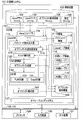
- FIG. 101 It is a figure which shows the structure of the computer system 101 with which JavaVM of embodiment of this invention operate
- FIG. 1 is a diagram showing a configuration of a computer system 101 on which Java VM according to the embodiment of this invention operates, and input / output data.
- the Java source file 104 described in the Java language is compiled by the Java compiler 109, so that the Java VM 110 is interpreted by interpreter execution and is described in byte code that is an executable format.
- a Java class file 103 is generated. Furthermore, a predetermined business process is executed by executing the Java class file 103 by the Java VM 110. Therefore, the Java class file 103 can be said to be a program for executing the predetermined business process.
- the computer system 101 includes hardware resources such as a processor (control unit) 129, a main storage (storage unit) 107, an auxiliary storage (storage unit) 102, an input device 130, and an output device 131.
- the processor 129, the main memory 107, the auxiliary memory 102, the input device 130, and the output device 131 are connected to each other via a bus 128.
- the processor 129 executes various processes by executing various programs stored in the main memory 107.
- the main memory 107 stores programs, information necessary for program execution, and program processing results.
- the main memory 107 may be a volatile memory or a non-volatile memory.
- the main memory 107 stores a Java compiler 109, a Java VM 110, a data area 108, and an operating system 127.
- the auxiliary storage 102 includes a Java class file 103 used for executing business processing, a Java source file 104 for generating the Java class file 103, an object analysis information file 105 used for storing object analysis information 126, and And a setting file 106 for recording a flag for controlling the operation of the Java VM 110 and a threshold value of the parameter.
- the input device 130 is an interface for inputting necessary information to the computer system 101.
- the input device 130 is, for example, a keyboard or a mouse.
- the output device 131 is a device that outputs information such as processing results to the outside.
- the output device 131 is, for example, a display.
- the data area 108 is an area for storing information necessary for program execution and the processing result of the program.
- the data area 108 includes byte code information 112 that is a byte code of a method, a Java heap area (first memory area) 115 that is an object storage area that is a GC target, and an external heap area (first memory area that is an object storage area that is not a GC target). 2 memory area) 116, and object analysis information 126 such as information relating to object generation and information relating to object profiling.
- the external heap area 116 is further secured and released as needed in the external heap area 116, such as the external heap 1 (117), the external heap 2 (118), the external heap 3 (119), and so on. Includes possible areas.
- the Java VM 110 stored in the main memory 107 will be described.
- the JavaVM 110 is a language processing execution system including a memory management mechanism that dynamically releases a memory area that is no longer needed.
- the JavaVM 110 includes a bytecode reading unit 111, an object generation destination changing unit 113, a method executing unit 114, a memory managing unit 120, and an object analyzing unit 125.
- the bytecode reading unit 111, the object generation destination changing unit 113, the method execution unit 114, the memory management unit 120, and the object analysis unit 125 are programs executed by the processor 129.
- the bytecode reading unit 111 reads the bytecode of the method from the Java class file 103 received by the JavaVM 110, and generates bytecode information 112 related to the method in the data area 108. At that time, when the object generation destination of the object generation instruction existing in the bytecode information 112 is changed by executing the object generation destination changing unit 113, or when the object analysis information 126 related to the bytecode information 112 is generated and updated. There is. Details of the processing of the bytecode reading unit 111 will be described with reference to FIG.
- the object generation destination changing unit 113 refers to the object generation information table 301 (see FIG. 4) and changes the object generation destination related to the object generation instruction from the Java heap area 115 to the external heap area 116 as appropriate. Details of the processing of the object generation destination changing unit 113 will be described with reference to FIG.
- the method execution unit 114 executes a method in accordance with each instruction of the bytecode information 112.
- the object generation unit 121 is requested to perform object generation processing (object generation processing request).
- the method execution unit 114 first executes the method as an interpreter.
- the instruction sequence of the bytecode information 112 is dynamically compiled, and the method is compiled code execution. Note that the method execution unit 114 may interpret the method from the beginning to the end, or may execute the compiled code from the beginning.
- the method execution unit 114 stops executing the compile code of the method and temporarily returns to interpreter execution. Processing may continue. Details of the process of the method execution unit 114 will be described with reference to FIG.
- the memory management unit 120 manages the memory area used by the JavaVM 110.
- the memory management unit 120 includes an object generation unit 121 and a GC unit 122.
- the object generation unit 121 When the object generation unit 121 receives the object generation processing request from the method execution unit 114, the object generation unit 121 attempts to generate an object in the Java heap area 115 or the external heap area 116 in accordance with the content of the object generation processing request. Here, when the area for generating the object is empty and the object generation is successful, the generated object is returned to the caller. On the other hand, when there is no free space in the Java heap area 115 and object generation to the Java heap area 115 fails, the GC unit 122 is requested to perform a GC process (GC process request), and the GC unit 122 executes the GC process. The memory area that is no longer necessary in the Java heap area 115 is released.
- GC process request a GC process
- the object generation is attempted again, and if it further fails, an error of insufficient memory is generated. If there is no free space in the external heap area 116 and the object generation in the external heap area 116 fails, the object generation in the Java heap area 115 is attempted. Furthermore, when the object generation to the Java heap area 115 also fails, the GC section 122 is requested to perform the GC process, and the GC section 122 executes the GC process to release the memory area that is no longer needed in the Java heap area 115. To do. Then, the object generation is attempted again, and if it further fails, an error of insufficient memory is generated.
- the object generation unit 121 records an object ID for identifying the generated object as an object generated by the object generation instruction in the generated object, and generates the object by the object generation instruction. This may be recorded in the object profiling information table 302 (see FIG. 5). Details of the processing of the object generation unit 121 will be described with reference to FIG.
- the GC unit 122 includes a CopyGC unit 124 and a FullGC unit 123.
- the GC unit 122 receives the GC processing request from the object generation unit 121, the GC unit 122 actually sends the copy GC unit 124 when the New region is exhausted and the FullGC unit 123 when the Old region is exhausted. Request GC processing. Details of the processing of the GC unit 122 will be described with reference to FIG.
- the copy GC unit 124 executes a copy GC for only the New area in the Java heap area 115.
- the object that has been moved from the New area to the Old area of the Java heap area 115 by CopyGC is an external heap 117 (one of the external heaps secured in the external heap area 116 from the New area. ),
- unnecessary external heap 117 is released, and by executing the object generation destination changing unit 113, the object generation instruction of the object generation instruction existing in the bytecode information 112 is generated. The destination may be changed. Details of the processing of the CopyGC unit 124 will be described with reference to FIG.
- the FullGC unit 123 executes FullGC for all the GC target areas including the New area and the Old area in the Java heap area 115.
- the object analysis unit 125 may be executed to execute object profiling processing. Details of the processing of the FullGC unit 123 will be described with reference to FIG.
- the object analysis unit 125 dynamically detects the starting object corresponding to the root of the reference relationship by analyzing the reference relationship of the long-lived object released in the Old area by FullGC. Then, for each object generation instruction, the number of times the starting object generated by the object generation instruction is released in the Old area by FullGC is profiled. For the member object referenced from the starting point object, the number of times that the member object is released together with the starting point object being released is profiled. Details of the processing of the object analysis unit 125 will be described with reference to FIG.
- the Java VM 110 has a flag for controlling the operation (hereinafter referred to as “setting flag”) and a parameter threshold value (hereinafter referred to as “setting threshold value”).
- setting flag a flag for controlling the operation
- setting threshold value a parameter threshold value
- the default values of the setting flag and the setting threshold value can be changed by specifying them in the setting file 106 or the input device 130.
- the JavaVM 110 detects the objects to be stored in the external heap area 116 by analyzing the reference relationship of the long-lived objects released in the Old area by FullGC, and stores these objects in the external heap area 116. , FullGC will be suppressed.
- the object analysis information file 105 in which the analysis result of the reference relation of a long-lived object released in the Old area by FullGC is used, the object to be stored in the external heap area 116 is changed by the operation change of the Java VM 110 by the setting flag.
- the object profiling for detection may not be performed, and the execution may be performed in a state in which FullGC is suppressed from the time when the Java VM 110 is activated.
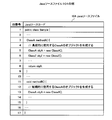
- FIG. 2 is a diagram illustrating an example of the Java source file 104 described in the Java language.
- Lines 1 to 17 show the contents of the Sample class.
- the third to ninth lines and the eleventh to fifteenth lines indicate the contents of the processing of the methodA () method and the methodB () method, respectively.
- Lines 5 and 13 use the new operator to instruct the Java heap area 115 to generate an object whose class type is ClassA.
- the 6th line instructs the new operator to generate an object whose class type is ClassZ in the Java heap area 115.
- methodA () is executed five times, five objects whose class type is ClassA and five objects whose class type is ClassZ are generated.
- methodB () is executed 10 more times, another 10 objects whose class type is ClassA are generated.
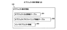
- FIG. 3 is a diagram illustrating an example of the object analysis information 126 according to the embodiment of this invention.
- the object analysis information 126 stores object analysis information related to the bytecode information 112, and includes an object generation information table 301, an object profiling information table 302, and member object information 303. Details of the member object generation information table 301, the object profiling information table 302, and the member object information 303 will be described with reference to FIGS. 4, 5, and 6, respectively.
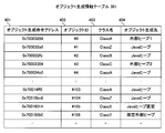
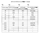
- FIG. 4 is a diagram illustrating an example of the object generation information table 301 according to the embodiment of this invention.
- Each row of the object generation information table 301 stores information related to an object generation command, and includes an object generation command address 401, an object ID (Identifier) 402, a class name 403, and an object generation destination 404.
- the object generation instruction address 401 stores the position of the object generation instruction.
- the position of the object generation instruction is, for example, an address where the object generation instruction exists in the bytecode information 112 corresponding to the object generation instruction such as the new operator in the example of the Java source file 104 shown in FIG. Note that, for example, when the object analysis information 126 is stored in the object analysis information file 105, the position of the object generation instruction may be indicated by an offset from the beginning of the bytecode information 112 to the position where the object generation instruction exists.
- the object ID 402 stores a unique value assigned for each object generation command.
- the object ID field 702 (see FIG. 7) of the object that is the object of the object profiling process stores the object ID 402 related to the object generation command that generated the object. Thereby, it can be determined by which object generation instruction the object is generated. For example, in the example of the Java source file 104 shown in FIG. 2, an object whose generation type is ClassA in line 5 and an object whose generation type is classA in line 13 are class A.
- the object IDs stored in the object header 701 are different such as # 0 and # 4. On the other hand, even if there are multiple objects whose class type is ClassA in the fifth line, the same object ID is # 0 for objects with the same position where the object is generated become.
- the class name 403 stores the name of the class type of the object generated by the object generation command.
- the object generation destination 404 stores the generation destination of the object generated by the object generation command.
- the object generation destination is “Java heap area” in the initial state, but is changed to “external heap 1” by the object generation destination changing unit 113 according to the result of the object profiling process.
- the object generation destination is set to “Java heap fixed” so that the object generation destination changing unit 113 does not change it, or “designated external heap” is set, so that the explicit memory management API (explicit memory management) ("API" is an abbreviation for "application programming interface”). Note that an object generated in the external heap specified by the explicit memory management API is released by the explicit memory management API, and is not automatically released for each unnecessary external heap 117. Details of the object profiling process will be described with reference to FIG.
- FIG. 5 is a diagram illustrating an example of the object profiling information table 302 according to the embodiment of this invention.
- the object profiling information table 302 stores the result of the object profiling process for the object associated with the object ID 402, and includes an object ID 501, an object generation count 502, an object profiling count 503, and a member object information address 504.
- the object ID 501 stores an object ID for linking the row data of the object generation information table 301 and the row data of the object profiling information table 302.
- this object ID By searching using this object ID as a key, the row data of the object generation information table 301 and the row data of the object profiling information table 302 for the object identified by this object ID can be referred to.
- the row data of the object profiling information table 302 is prepared in advance for the row data of the object generation information table 301, the row data of the object generation information table 301 and the row data of the object profiling information table 302 are in a one-to-one relationship.
- the object generation information table 301 and the object profiling information table 302 may be combined into one table.
- the row of the object profiling information table 302 with respect to the row data of the object generation information table 301 is stored. Data may be registered.
- the row data of the object profiling information table 302 is prepared in advance for the row data of the object generation information table 301.
- the object generation information table 301 and the object profiling information table 302 are separately provided. It is shown as a table.
- the object generation number 502 stores the number of times the object identified by the object ID 501 is actually generated by the object generation command related to the object ID 501.
- the object profiling count 503 stores the number of times the object stored in the Old area identified by the object ID 501 has been released by FullGC, that is, the number of times the object profiling processing has been performed on the object identified by the object ID 501. To do. Details of the object profiling process will be described with reference to FIG.
- the member object information address 504 stores the address of the member object information 303 related to the object identified by the object ID 501. Details of the member object information 303 will be described with reference to FIG.
- FIG. 6 is a diagram showing an example of member object information 303 according to the embodiment of this invention.
- the member object information 303 stores information about the state of reference relations of objects profiled by the object profiling process, and a data structure for storing information about the starting object (hereinafter referred to as “starting object data structure”). And a data structure for storing information about member objects (hereinafter referred to as “member object data structure”).
- the starting object is an object stored in the Old area that is the starting point of the object profiling process, and is no longer referenced from the root set or the required object after the end of the previous FullGC and before the start of the current FullGC. An object or an object that is highly likely not to be referenced from a root set or a necessary object.
- member objects are objects that are released together when the starting object is released by FullGC, or may be released together. It is a high object. Details of the object profiling process will be described with reference to FIG.
- the member object information 303 is shown as a tree structure in which the starting object data structure 601 and the member object data structures 602 to 607 are connected by pointers.
- the starting object data structure is indicated by a double-line rectangle
- the member object data structure is indicated by a single-line rectangle.
- the origin object data structure 601 stores a pointer to the member object data structure corresponding to the member object for each object reference field in order to record the status of the reference relationship from the origin object to the reference member object.
- an example of the embodiment of the present invention indicates that the starting object data structure 601 connects the member object data structure 602 and the member object data structure 603 by pointers.
- the member object data structures 602 to 607 store a pointer to the member object data structure corresponding to the reference destination member object for each object reference field in order to record the status of the reference relationship from the member object to the reference destination member object.
- a pointer indicates that the member object data structure 603 connects the member object data structure 605 and the member object data structure 606 with a pointer.
- the pointer 608 indicates that an object whose class type is ClassF has an object reference field, but an object referred to by the object reference field is not recorded (NULL).
- the member object data structures 602 to 607 include the name of the class type of the member object and the number of times the member object is released together with the origin object being released by FullGC, that is, object profiling for the origin object.
- the number of times the object profiling process is executed for the member object (hereinafter referred to as “member object profiling count”) is stored.
- the number of times that the member object of ClassE indicated by the member object data structure 605 is also released together with the release of the origin object indicated by the origin object data structure 601 by FullGC. Indicates twice.
- the number attached to the pointer indicates the member object relevance ratio for convenience.
- the member object conformance rate is a rate at which the member object is released together with the origin object being released by FullGC.
- the membership rate of the ClassF member object indicated by the member object data structure 606 is 0.75 because the starting object of ClassA indicated by the member object data structure 601 is released four times and the member object of ClassF is released three times. become.
- the ClassG member object relevance ratio indicated by the member object data structure 607 is 0.25 because the ClassG member object is released once out of the ClassA starting object indicated by the member object data structure 601 being released four times. become.
- a broken line indicates a convenient boundary where the member object matching rate is 0.6, and an inner side surrounded by the broken line indicates that the member object matching rate is 0.6 or more.
- the member object information address 504 stores the address of the starting object data structure as the address of the member object information 303.
- 0x81b2e23c which is the address of the starting object data structure 601 is stored in the member object information address 504 for the object whose object ID is # 4 stored in the object ID 501. It shows that.
- the starting object data structure 601 includes an object ID (subscript number “4”), an object class type name (Class A), and the number of profiling executions (number in parentheses). "4") is stored for convenience.
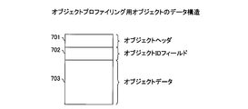
- FIG. 7 is a diagram showing an example of the data structure of the object profiling object according to the embodiment of the present invention.
- the object profiling object includes an object header 701, an object ID field 702, and object data 703.
- the object profiling object is an object to be subjected to object profiling processing.
- the object header 701 is object management information.
- the object ID field 702 stores an object ID for identifying the object. This object ID is the object ID 402 related to the object generation command that generated the object.
- the data structure of a normal object that is not the object of object profiling processing includes an object header 701 and object data 703. Even if the object is to be subjected to object profiling processing, if the object ID can be identified by storing the object ID in an empty area of the object header 701, the object data 703, and an area other than the data structure of the object, the object ID field There is no need to secure a separate area.
- the object data 703 is the data body of the object.
- the lower-order bits of the pointer to the object can be set to 0 according to the size of the object header 701, and can be used as a bit flag. For example, when the size of the object header 701 is 8 bytes, the lower 3 bits of the pointer to the object are 0. In the embodiment of the present invention, the lower-order bits of the pointer to the object may be used as a bit flag.
- FIG. 8 is a diagram illustrating an example of the object type bit according to the embodiment of this invention.
- the value of the object type bit 802 corresponds to the object type 801.
- 2 bits included in the object header 701 are used as object type bits.
- the object type bit 802 when the object type bit 802 is “00”, it indicates that the object is an “unanalyzed” object that is an unanalyzed object in the GC process or the object profiling process. Further, when the object type bit 802 is “01”, it indicates that the object is a “necessary” object that has been determined to be an object necessary for program execution in the FullGC process. Similarly, when the object type bit 802 is “10”, the object is a starting point of the object profiling process, and an object that is not referred to by a necessary object between the previous FullGC and the current FullGC, or This indicates that the object is a “starting point” object that is highly likely not to be referenced from the necessary object.
- object type bit 802 when the object type bit 802 is “11”, among objects that can be reached by sequentially following the object reference from the starting object, objects that are released together when the starting object is released by FullGC, or , Indicating that the object is a “member” object that is likely to be released together.
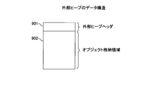
- FIG. 9 is a diagram illustrating an example of a data structure of the external heap 117 according to the embodiment of this invention.
- the external heap 117 includes an external heap header 901 and an object storage area 902.
- the external heap header 901 is object management information, and stores the address of the member object information 303 stored in the member object reference information address 504 relating to the object generation instruction that generated the starting object stored in the external heap 117.
- the object storage area 902 is an area for storing an object.
- FIG. 13 is a flowchart showing a procedure of byte code reading processing according to the embodiment of the present invention. This process is executed when the processor 129 processes the byte code reading unit 111. A description of FIGS. 10 to 12 will be given later.
- the bytecode reading unit 111 When the processor 129 executes the bytecode reading unit 111, the bytecode reading unit 111 first reads the bytecode of the method from the Java class file 103 received by the JavaVM 110, and stores the bytecode information 112 related to the method in the data area 108. Generate (step 1301).
- the JavaVM 110 setting flag is referenced to determine whether or not to change the object generation destination of the object generation instruction existing in the bytecode information 112 related to the method at the time of bytecode reading processing. (Step 1302).
- step 1302 When the object generation destination is changed (the result of step 1302 is “YES”), the execution result of the object analysis information related to the method stored in the object analysis information file 105 accepted by the Java VM 110 is stored in the object analysis information 126.
- the object generation destination changing unit 113 is executed on the object indicated by the row data that is read and registered in the object profiling information table 302 related to the method, and the object generation destination changing process is executed (step 1303).
- Step 1304 it is determined whether or not object profiling is performed with reference to the setting flag of JavaVM 110 (Ste 1304).
- the object analysis information 126 related to the bytecode information 112 generated in the processing of step 1301 is generated, and all objects existing in the bytecode information 112 are generated.
- the object generation instruction address, the unique object ID assigned to the object generation instruction, and the class name of the object generated by the object generation instruction are respectively an object generation instruction address 401, an object ID 402, and a class name. Registered in 403 (including update). Further, the object generation destination 404 is registered in the “Java heap area” (step 1305).
- step 1303 for an object generation instruction that reflects the execution result of the object analysis information related to the method stored in the object analysis information file 105 received by the JavaVM 110 in the object analysis information 126, step 1305 Do not perform the process.
- step 1304 If the object profiling is not performed (the result of step 1304 is “NO”), or after the process of step 1305 ends, this process ends.
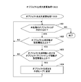
- FIG. 14 is a flowchart showing a procedure of object generation destination change processing 1303 according to the embodiment of this invention. This processing is executed when the processor 129 processes the object generation destination changing unit 113.
- the object generation destination changing unit 113 When the processor 129 executes the object generation destination changing unit 113, the object generation destination changing unit 113 first determines whether or not an unprocessed object ID exists in the object ID 501 in the object profiling table 302 to be processed ( Step 1401).
- the object generation count 502 of the object identified by the object ID is the set threshold value (first threshold value) of the Java VM 110. It is determined whether or not this is the case (step 1402). In this step 1402, it is determined whether or not object generation has been performed a sufficient number of times to determine whether or not to change the object generation destination. For example, if the setting threshold for the number of object generations is 1000, an object generation command whose object ID 501 is # 0 has an object generation number 502 of 5872 (see FIG. 5). It can be determined that the object generation has been performed a sufficient number of times to determine whether or not.
- the object generation command with the object ID 501 of # 104 has the object generation count 502 of 950 (see FIG. 5), the number of objects sufficient to determine whether or not to change the object generation destination It can be determined that the generation has not been performed.
- the object profiling count 503 for the object generation count 502 associated with the object ID is the JavaVM 110 set threshold (second threshold). It is determined whether or not this is the case (step 1403). In this step 1403, the height of the rate at which the object generated by the object generation command related to the object ID is released by FullGC, that is, the object generated by the object generation command should be stored in the external heap area. It is determined whether or not the object generation destination of the object generation instruction should be changed to the external heap area based on the high ratio of becoming a long-lived object.
- the setting threshold value (ratio) of the object profiling count with respect to the object generation count is 0.50
- the object generation destination 404 associated with the object ID is set to “ For example, it is changed to “external heap area 1” other than “Java heap area” (step 1404).
- step 1402 If the object generation count 502 is not greater than or equal to the set threshold (the result of step 1402 is “NO”), the object profiling count 503 for the object generation count 502 is not greater than or equal to the set threshold (the result of step 1403 is “NO”), or After the processing of 1404 is completed, the processing returns to step 1401. Then, the execution of this process is continued for the unprocessed object ID.
- the comparison target value may be weighted according to the class size of the object related to the object ID.
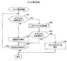
- FIG. 15 is a flowchart illustrating a procedure of method execution processing according to the embodiment of this invention. This process is executed when the processor 129 processes the method execution unit 114.
- the bytecode information 112 related to the execution target method generated by the bytecode reading unit 111 includes one or more instructions, and an instruction type is assigned to each instruction.
- the method execution unit 114 When the processor 129 executes the method execution unit 114, the method execution unit 114 first determines whether or not the instruction type of the method to be executed is an object generation instruction (step 1501).
- step 1504 If the instruction type is not an object generation instruction (the result of step 1501 is “NO”), the instruction is executed (step 1504). If the instruction type is an object generation instruction (the result of step 1501 is “YES”), the object generation unit 121 is executed to execute object generation processing (step 1502).
- step 1503 After the processing in step 1502 is completed, it is determined whether or not the object has been successfully generated (step 1503). If the object generation has failed (the result of step 1503 is “NO”), the execution of the method is interrupted and a memory shortage error is generated (step 1505).
- step 1506 If the object has been successfully generated (the result of step 1503 is “YES”), or after the processing of step 1504 is completed, it is determined whether there is an instruction to be executed next (step 1506). If there is an instruction to be executed next (the result of step 1506 is “YES”), the process of step 1501 is executed and the method execution process is continued.
- step 1506 When there is no instruction to be executed next, that is, when all the instructions have been processed (the result of step 1506 is “NO”), or after the process of step 1505 is ended, this process ends.
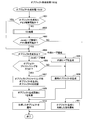
- FIG. 16 is a flowchart showing a procedure of object generation processing 1502 according to the embodiment of this invention. This processing is executed when the processor 129 processes the object generation unit 121.
- the object generation unit 121 When the processor 129 executes the object generation unit 121, the object generation unit 121 first obtains an amount of memory necessary for generating the object requested to be generated from the object generation destination 404 related to the object generation instruction (see FIG. 4). It is determined whether or not the object generation destination stored in (1) can be secured. If the object generation destination is the external heap area 116 and the amount of memory necessary for generating the object requested to be generated cannot be secured in the external heap area 116, the object requested to be generated is further generated. It is determined whether or not a sufficient amount of memory can be secured in the Java heap area 115. (Step 1601).
- step 1601 When an amount of memory necessary for generating the object requested to be generated cannot be secured in the object generation destination (the result of step 1601 is “NO”), an unnecessary memory area in the Java heap area 115 is released. Then, the GC unit 122 is executed to execute the GC process (step 1602).
- step 1603 After the execution of the process of step 1602, it is determined again whether or not the amount of memory required to generate the object requested to be generated can be secured in the Java heap area 115 (step 1603).
- step 1603 If the amount of memory required to generate the object requested to be generated cannot be secured in the Java heap area 115 (the result of step 1603 is “NO”), the object generation has failed in the object generation process execution source. This is notified (step 1611).
- Step 1601 or Step 1603 When the amount of memory necessary for generating the object requested to be generated can be secured in the object generation destination (the result of Step 1601 or Step 1603 is “YES”), where is the current object generation destination? It is determined whether or not there is (step 1604).
- the setting flag of the Java VM 110 is referenced to determine whether or not to perform object profiling (step 1606).
- step 1606 When object profiling is performed (the result of step 1606 is “YES”), an object profiling object is generated in the Java heap area 115, and the object for identifying the object generated by the object generation instruction The object ID 402 related to the generation command is recorded in the object ID field 702 of the object (step 1607).
- step 1607 After the process of step 1607 is completed, in order to record that the object has been generated by the object generation instruction, 1 is added to the value of the object generation count 502 related to the object generation instruction, and the object profiling information table 302 is stored. Update (step 1609).
- the external heap 117 that is the object generation destination is generated. Then, the member object information address 504 related to the generation instruction is recorded in the external heap header 901 of the external heap 117 (step 1605).
- the initial size when the external heap is generated is the sum of the class size of the starting object related to the generation instruction and the class size of the member object whose member object conformance rate is equal to or greater than the set threshold according to the generation instruction. Set based on.
- step 1606 When object profiling is not performed (the result of step 1606 is “NO”), or after the processing of step 1605 ends, a normal object that does not include the object ID field 702 is generated in the object generation destination (step 1608).
- step 1608 After the process of step 1608 is completed or after the process of step 1609 is completed, the generated object is notified to the execution source of the object generation process (step 1610). After the process of step 1610 is finished or after the process of step 1611 is finished, this process is finished.
- a dedicated object generation instruction according to whether the object generation destination or object profiling is performed and an object generation process corresponding thereto are prepared, and a predetermined object generation is performed by appropriately rewriting the object generation instruction of the bytecode information 112 Processing may be executed. In that case, for example, the determination in step 1604 and step 1607 may be unnecessary.
- FIG. 17 is a flowchart showing a procedure of the GC processing 1602 according to the embodiment of this invention. This process is executed when the processor 129 processes the GC unit 122. When the processor 129 executes the GC unit 122, the GC unit 122 first determines whether the area depleted in the object generation processing 1502 is the New area or the Old area of the Java heap area 115 (step 1701).
- Step 1701 If the area depleted in the object generation process 1502 is the New area of the Java heap area 115 (the result of Step 1701 is “New area”), the CopyGC unit 124 is executed and the CopyGC process is executed (Step 1702). ).
- Step 1703 the FullGC unit 123 is executed and the FullGC process is executed (Step 1703). ). After the process of step 1702 is completed or after the process of step 1703 is completed, this process is terminated.
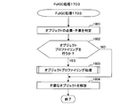
- FIG. 18 is a flowchart showing a procedure of FullGC processing 1703 according to the embodiment of this invention. This processing is executed when the processor 129 processes the FullGC unit 123.
- the FullGC unit 123 When the processor 129 executes the FullGC unit 123, the FullGC unit 123 first sets the object type “unanalyzed” in the object header 701 for all objects that are the target of the full GC. In addition, in order to indicate that the object is necessary for the execution of the subsequent program, an object that can be reached by sequentially tracing the object reference from the root set such as a register, a stack at the time of execution, and a global variable is displayed in the object header 701. Set the object type “Necessary”. Then, after tracing all the objects that can be reached from the root set, an object whose object type is “necessary” in the object header 701 is an object necessary for execution of the subsequent program, and the object type of the object header 701 is “unanalyzed”. Is determined as an object unnecessary for the subsequent program execution (step 1801).
- FIG. 10 is a diagram illustrating the state of the objects stored in the old area of the Java heap area 115 at the end of the process of step 1801 of the full GC process 1703 according to the embodiment of this invention.
- Each node represents an object.
- An object indicated by a double circle is an object in which the object type “necessary” is set in the object header 701 by the processing of Step 1801 of the FullGC processing 1703.
- the symbol in the node indicates the class name, and the number on the lower right of the class name indicates the object ID stored in the object ID field 702.
- a solid line arrow is an object reference traced by the process of step 1801 of the FullGC process 1703
- a broken line arrow is an object that has an object reference but has not been traced by the process of step 1801 of the FullGC process 1703 Indicates a reference.
- Root set 1001 is a register, a runtime stack, a global variable, and the like.
- Step 1801 of the FullGC processing 1703 is executed starting from the object reference held in the route set 1001
- all objects reachable by sequentially tracing the object reference from the route set 1001 are determined as necessary objects. Therefore, as shown in FIG. 10, objects indicated by double circles such as an object 1002, an object 1003, an object 1004, and an object 1005 are necessary objects.
- all objects that could not be reached by sequentially tracing object references from the root set 1001 are determined as unanalyzed objects (unnecessary objects). Therefore, as shown in FIG. 10, objects indicated by single circles such as an object 1006, an object 1007, and an object 1008 are unanalyzed objects.
- unanalyzed objects are objects that are actually released by the FullGC process 1703, but are stored in the external heap area 116 in order to suppress the usage of the Old area of the Java heap 115 and to suppress the occurrence of the FullGC process 1703. However, it is desirable to release it regardless of GC.
- starting objects such as the object 1006, the object 1007, and the object 1008 corresponding to the root of the reference relation in the reference relation of the unanalyzed object are not referred to from the root set 1001 or the necessary object, so that the object is changed from the starting object.
- Objects that can only be reached by tracing sequentially are also released. Therefore, if the reachable objects are stored in the external heap area 116 by sequentially tracing the objects from the starting object including the starting object, the Old usage of the Java heap 115 can be further suppressed. For this purpose, it is necessary to identify starting objects and generate these starting objects in the external heap area 116. A method of specifying the starting object object will be described with reference to FIG.
- step 1801 it is determined whether or not object profiling is performed with reference to the setting flag of JavaVM 110 (step 1802).
- step 1802 When performing object profiling (the result of step 1802 is “YES”), the object analysis unit 125 is executed to execute object profiling processing (step 1803).
- step 1802 When object profiling is not performed (the result of step 1802 is “NO”), or after the processing of step 1803 ends, an object whose object type is not “necessary” in the object header 701 is released as an unnecessary object (step 1804). ). After the process of step 1804 is completed, this process is terminated.
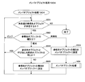
- FIG. 19 is a flowchart showing a procedure of object profiling processing 1803 according to the embodiment of this invention. This processing is executed when the processor 129 processes the object analysis unit 125. By executing the processing from step 1901 to step 1904 of this processing, the starting object can be specified.
- step 1901 it is first determined whether or not there is an unprocessed unnecessary object for all the objects determined as unnecessary in step 1801 (step 1901).
- step 1901 If an unprocessed unnecessary object exists (the result of step 1901 is “YES”), the object type of the object header 701 of the object is referred to and it is determined whether the object type is “unanalyzed”. (Step 1902).
- step 1902 If the object type is “unanalyzed” (the result of step 1902 is “YES”), the object type of the object header 701 of the object is set to “starting point” (step 1903).
- step 1903 After completion of the processing of step 1903, member object processing is called for the starting object of step 1903, and member object processing is executed (step 1904).
- step 1902 If the object type is not “unanalyzed” (the result of step 1902 is “NO”), or after the process of step 1904 is completed, the process returns to step 1901. Then, the execution of this process is continued for the unprocessed unnecessary object.
- the object ID field 702 of the starting object is referred to for the starting object whose object type is “starting” in the object header 701, and Get the object ID of the origin object. Then, 1 is added to the value of the object profiling count 503 related to the object ID, and the object profiling information table 302 is updated. Further, the member object information 303 related to the origin object is referred to by the pointer stored in the member object information address 504 related to the object ID. If member object information 303 relating to the starting object does not exist, member object information 303 relating to the starting object is generated.
- the member object data structure is appropriately added to the member object information 303, and the corresponding member object data structure
- the member object information 303 is updated by adding 1 to the member object profiling count stored in (step 1905). After the process of step 1905 ends, this process ends.
- FIG. 20 is a flowchart showing a procedure of member object processing 1904 according to the embodiment of this invention. This process is executed by being called from the object profiling process 1803 or recursively called from the member object process 1904.
- step 2001 it is first determined whether or not there is an unprocessed reference destination object for the object that is the processing target of this processing (step 2001). If there is an unprocessed reference destination object (the result of step 2001 is “YES”), the object type is determined by referring to the object type of the object header 701 of the reference destination object (step 2002).
- step 2003 it is determined whether or not the reference destination object is the same as the calling source starting object of the member object processing 1803 (step 2003). . If the reference destination object is not the same as the calling source object of the member object processing 1803 (the result of step 2003 is “NO”), the object type of the object header 701 of the reference destination object is set to “member” (step) 2005).
- step 2004 the object type of the object header 701 of the reference destination object is set to “member” (step 2004).
- member object processing 1904 is executed for the referenced object (step 1904).
- step 2002 when the object type is “member” (the result of step 2002 is “member”), when the reference destination object is the same as the calling source object of the member object processing 1803 (the result of step 2003 is “YES”). After the process of step 2005 is completed or after the process of step 1904 executed after step 2004 is completed, the process returns to step 2001. Then, the execution of this process is continued for an unprocessed reference destination object (the result of step 2001 is “YES”). If there is no unprocessed reference destination object (the result of step 2001 is “NO”), this process ends.
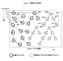
- FIG. 11 is a diagram showing a specific procedure for identifying the starting object by executing the processing from step 1901 to step 1904 of the object profiling processing 1803 according to the embodiment of this invention.
- Each node represents an object.
- An object indicated by a single circle of a thin line is an unnecessary object in which the object type “unanalyzed” is still set in the object header 701 by the processing of step 1801 of the full GC processing 1703.
- the symbol in the node indicates the class name, and the number on the lower right of the class name indicates the object ID stored in the object ID field 702.
- the arrows connecting the objects indicate the object reference relationship.
- a solid line arrow is an object reference traced by executing the processing from step 1901 to step 1904 of the object profiling process 1803, and a broken line arrow is a step 1901 of the object profiling process 1803 although an object reference exists. The object reference which has not been traced yet by executing the processing from step 1904 to step 1904 is shown.
- FIG. 11A shows a state at the end of the process of Step 1801 of the FullGC process 1703. It is assumed that the objects are processed in the order of the object 1009, the object 1011, the object 1008, the object 1010, and the object 1012 from a state in which the object reference relationship is not known.
- FIG. 11B processes the object 1009 and sets the object type of the object header 701 of the object 1009 to “starting point” because the object type is “unanalyzed” in the determination in step 1902 of the object profiling process 1803. Indicates the state. As a result, the starting object 1009 is indicated by a single circle with a bold line.
- FIG. 11C processes the object 1011 that is the reference destination of the object 1009, and the object type is “unanalyzed” in step 2002 of the member object processing 1904. Therefore, the object type of the object header 701 of the object 1011 Indicates that “Member” is set. As a result, the object 1011 which is a member object is indicated by a single circle with a cross. Since the reference destination object of the object 1011 does not exist, the processing of the object 1009 ends here. Further, since the object 1011 is processed and the object type is not “unanalyzed” in the determination in step 1902 of the object profiling process 1803, the process of the object 1011 is ended here.
- FIG. 11D processes the object 1008 and sets the object type of the object header 701 of the object 1008 to “starting point” because the object type is “unanalyzed” in the determination in step 1902 of the object profiling process 1803. Indicates the state.
- FIG. 11 (e) processes the object 1009 that is the reference destination of the object 1008, the object type is “starting point” in the determination in step 2002 of the member object processing 1904, and in the determination in step 2003 of the member object processing 1904, Since the reference destination object 1009 and the call source object 1008 are not the same, the object type of the object header 701 of the reference destination object 1009 is set to “member”. In addition, since the object 1010 that is the reference destination of the object 1008 is processed and the object type is “unanalyzed” in the determination of step 2002 of the member object processing 1904, the object type of the object header 701 of the object 1010 that is the reference destination is changed. The state set to “Member” is shown.
- the object 1012 that is the reference destination of the object 1010 is processed, and the object type is “unanalyzed” in the determination in step 2002 of the member object processing 1904. Therefore, the object type “in the object header 701 of the object 1012 that is the reference destination” This shows a state in which “Member” is set.
- the object 1008 that is the reference destination of the object 1012 has the object type “starting point” in the determination in step 2002 of the member object processing 1904, and is the same as the calling object 1008 in the determination in step 2003 of the member object processing 1904. Therefore, the processing of the object 1008 ends here.
- the object 1010 is processed and the object type is not “unanalyzed” in the determination in step 1902 of the object profiling processing 1803, the processing of the object 1010 ends here. The same applies to the object 1012.
- FIG. 11 (f) shows a state in which all the processing of the object 1009, the object 1011, the object 1008, the object 1010, and the object 1012 has been completed, and it is determined that the object 1008 is the starting object by analyzing the reference relationship of this object. Can be identified. Further, the object 1009, the object 1011, the object 1010, and the object 1012 are member objects, and the object reference 1013 from the member object to the starting object is processed as not existing.
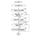
- FIG. 21 is a flowchart showing a procedure of CopyGC processing 1702 according to the embodiment of this invention. This process is executed when the processor 129 processes the CopyGC unit 124.
- the CopyGC unit 124 When the processor 129 executes the CopyGC unit 124, the CopyGC unit 124 first moves the objects necessary for the subsequent program execution stored in the New area to another area in the New area and moves them. The object that did not exist is released as an unnecessary object (step 2101). In the process of step 2101, for an object that can be reached by sequentially tracing object references from the starting object stored in the external heap area 116, the member object moving process is called for the starting object to move the member object. By executing the process, it is moved to an appropriate destination. Details of the member object movement processing will be described with reference to FIG.
- step 2101 After the processing of step 2101 is completed, for example, an object reference to the external heap 117 is inspected, and it is determined whether or not there is an unnecessary external heap 117 that is not referenced from anywhere (step 2102). If there is an unnecessary external heap 117 (the result of step 2102 is “YES”), by releasing the unnecessary external heap area 116, for example, the external heap 1 or the external heap 3, the external heap 1 or the external heap The unnecessary object stored in 3 is released (step 2103).
- step 2104 If there is no unnecessary external heap 117 (the result of step 2102 is “NO”), or after the processing of step 2103 is completed, the setting flag of JavaVM 110 is referred to, and the object generation destination of the object generation instruction is specified during CopyGC processing. It is determined whether or not to change (step 2104). When changing the object generation destination (the result of step 2104 is “YES”), the object generation destination changing unit 113 is executed on the object generation information table 301 to execute the object generation destination changing process (step 1303). ). When the object generation destination is not changed (the result of step 2104 is “NO”), or after the processing of step 1303 is ended, this processing is ended.
- unnecessary external heap release and change of the object generation destination of the object generation instruction are performed at the time of CopyGC processing, but these processing are performed at a predetermined timing other than at the time of CopyGC processing. May be.
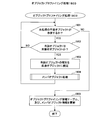
- FIG. 22 is a flowchart illustrating a procedure of member object movement processing according to the embodiment of this invention. This process is executed in the process of Step 2101 of the CopyGC process 1702.
- step 2201 it is first determined whether or not there is an unprocessed reference destination object for the object that is the processing target of this processing. If there is an unprocessed reference destination object (the result of step 2201 is “YES”), whether or not the reference destination object is a target to be moved from the New area to the Old area by the process of step 2101 of the CopyGC process 1702. Is determined (step 2202). Note that a reference object is a target to be moved from the New area to the Old area by CopyGC processing is a long-lived object that has undergone at least a number of CopyGCs to move the reference object to the Old area. Means.
- the member object relevance ratio of the reference destination object is equal to or greater than the setting threshold (third threshold) of the JavaVM 110 It is determined whether or not (step 2203). In this determination, the member object relevance ratio may be weighted according to the class size of the member object.
- the reference destination object is moved to the same external heap as the origin object (step 2204).
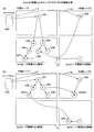
- FIG. 12 shows the New and Old areas of the external heap 1, the external heap 2 and the Java heap 115 at the start and (b) end of the member object move processing according to the embodiment of the present invention. It is a figure which shows the state of the stored object.
- Each node represents an object. Note that symbols in the nodes indicate class names. For example, the class name of the object 1201 whose symbol in the node is “A” is “ClassA”. An arrow connecting the objects indicates the reference relationship of the objects.
- the object 1201 is a starting object stored in the external heap 1.
- An object 1208 is a starting point object stored in the external heap 2.
- a pointer to member object information 303 related to the object 1201 is stored in the external heap header 901 of the external heap 1 in which the object 1201 is stored, and the member object information 303 related to the object 1201 is referred to by this pointer.
- a pointer to the member object information 303 related to the object 1208 is stored in the external heap header 901 of the external heap 2 in which the object 1208 is stored, and the member object information 303 related to the object 1208 is referred to by this pointer.
- the member object information 303 related to the object 1201 is the member object information 303 shown in FIG.
- the starting object data structure 601 of this member object information 303 it can be seen that the starting object of Class A has been released four times in the Old area by FullGC. Further, referring to the member object data structure 606 of the member object information 303, the ClassA member object is released three times in the Old area by releasing the starting object of ClassA by FullGC, the members of the member object information 303 With reference to the object data structure 605, it can be seen that the class A member object was released twice in the Old area by releasing the starting object of Class A by FullGC.
- the member object matching rates of ClassB, ClassC, ClassD, ClassE, ClassF, and ClassG are 1.00, 1.00, 1.00, 0.50, 0.75, and 0.25, respectively.
- a member object with a high member object conformance rate is likely to be unnecessary at the same time as the starting object becomes unnecessary, so by storing a member object with a high member object conformance rate in the same external heap as the starting object, At the same time as the starting object becomes unnecessary, releasing the external heap also increases the possibility of releasing a member object having a high member object matching rate. For this reason, in the member object moving process, a member object having a high member object matching rate is moved to the same external heap as the starting object object.
- the object 1202, the object 1203, the object 1204, and the object 1206 having the member object conformance rate of 0.60 or more are subject to the same external heap as the object 1201 by the member object moving process. Move to 1.
- the object 1205 whose member object relevance rate is not 0.60 or more moves to the same external heap 2 as the object 1208 which is another starting object whose result of step 2203 is “YES” by the member object moving process.
- the object 1207 is an object that can be reached by sequentially tracing the object reference from the starting object stored in the external heap area 116.
- the member object relevance rate is not 0.60 or more, the Old area of the Java heap area 115 Move to.
- step 2204 the member object movement process is called for the reference destination object, and the member object movement process is executed (step 2205).
- step 2202 When the reference destination object is not the object to be moved from the New area to the Old area (the result of step 2202 is “NO”), when the member object precision of the reference destination object is not equal to or greater than the set threshold (the result of step 2203 is “NO”). ), And after the process of step 2205 is completed, the process returns to the process of step 2201. Then, the execution of this process is continued for the unprocessed reference destination object. If there is no unprocessed reference destination object (the result of step 2201 is “NO”), this process ends.
- step 2202 the process of step 2202 may be omitted. That is, whether or not to move the reference object (member object) to the same external heap as the external heap in which the origin object exists may be determined only by the determination in step 2203. In other words, in some cases, it is more convenient to suppress the occurrence of GC by processing the referenced object to move to the same external heap as the starting object, even if the referenced object is not long enough to move to the Old area. . However, although it cannot be generally stated, it is effective to provide the determination in step 2202 and move a longer-lived reference destination object to the same external heap as the origin object, as in the processing of FIG.
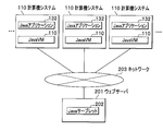
- a plurality of computer systems 101 and a web server 201 are communicably connected via a network 203.
- the computer system 101 has a Java application 132 that functions in accordance with the description content of the Java source file 104, and the Java VM 110 executes the Java application 132 to realize a predetermined service.
- the web server 201 is a computer having hardware resources such as an input device, an output device, a processor, and a storage device.
- the web server 201 has a Java servlet 202, for example.
- the web server 201 dynamically creates a web page by causing the Java servlet 202 to function, and transmits the web page to the computer system 101 that requested the web page.
- the computer system 101 may have a Java applet instead of the Java application 132.
- a predetermined service is realized by executing a Java applet using a web browser that browses a web page provided by the web server 201.
- the Java VM 110 included in the computer system 101 may be previously installed at the time of shipment, or may be acquired from the web server 201.
- the GC handled in this embodiment is a generational GC
- the GC to which the present invention is applicable is not limited to this.
- it can be applied to a parallel GC.
- the object profiling count 503 registered in the object profiling information table 302 may be the number of copy GCs or the number of other GCs instead of the number of full GCs.
Landscapes
- Engineering & Computer Science (AREA)
- Theoretical Computer Science (AREA)
- Physics & Mathematics (AREA)
- General Engineering & Computer Science (AREA)
- General Physics & Mathematics (AREA)
- Memory System (AREA)
- Devices For Executing Special Programs (AREA)
- Stored Programmes (AREA)
- Debugging And Monitoring (AREA)
Applications Claiming Priority (2)
| Application Number | Priority Date | Filing Date | Title |
|---|---|---|---|
| JP2009-236257 | 2009-10-13 | ||
| JP2009236257A JP5199975B2 (ja) | 2009-10-13 | 2009-10-13 | メモリ管理方法、メモリ管理プログラム、及び、情報処理装置 |
Publications (1)
| Publication Number | Publication Date |
|---|---|
| WO2011045949A1 true WO2011045949A1 (ja) | 2011-04-21 |
Family
ID=43876004
Family Applications (1)
| Application Number | Title | Priority Date | Filing Date |
|---|---|---|---|
| PCT/JP2010/053520 Ceased WO2011045949A1 (ja) | 2009-10-13 | 2010-03-04 | メモリ管理方法、メモリ管理プログラム、及び、情報処理装置 |
Country Status (2)
| Country | Link |
|---|---|
| JP (1) | JP5199975B2 (enExample) |
| WO (1) | WO2011045949A1 (enExample) |
Cited By (1)
| Publication number | Priority date | Publication date | Assignee | Title |
|---|---|---|---|---|
| CN110543357A (zh) * | 2018-05-28 | 2019-12-06 | 华为技术有限公司 | 管理应用程序对象的方法,相关装置及系统 |
Families Citing this family (1)
| Publication number | Priority date | Publication date | Assignee | Title |
|---|---|---|---|---|
| WO2014171002A1 (ja) * | 2013-04-19 | 2014-10-23 | 株式会社日立製作所 | メモリ管理方法、計算機及び記録媒体 |
Citations (4)
| Publication number | Priority date | Publication date | Assignee | Title |
|---|---|---|---|---|
| JP2003241967A (ja) * | 2002-02-15 | 2003-08-29 | Matsushita Electric Ind Co Ltd | プログラム実行装置およびその方法、並びにそこで実行されるプログラム |
| US6681234B2 (en) * | 2000-12-12 | 2004-01-20 | Sun Microsystems, Inc. | Method and apparatus for storing long-lived objects in a virtual machine |
| US20070180002A1 (en) * | 2006-01-27 | 2007-08-02 | Sun Microsystems, Inc. | Method and apparatus for reducing object pre-tenuring overhead in a generational garbage collector |
| JP2010044532A (ja) * | 2008-08-11 | 2010-02-25 | Hitachi Ltd | メモリ管理方法、メモリ管理プログラム、および、メモリ管理装置 |
-
2009
- 2009-10-13 JP JP2009236257A patent/JP5199975B2/ja not_active Expired - Fee Related
-
2010
- 2010-03-04 WO PCT/JP2010/053520 patent/WO2011045949A1/ja not_active Ceased
Patent Citations (4)
| Publication number | Priority date | Publication date | Assignee | Title |
|---|---|---|---|---|
| US6681234B2 (en) * | 2000-12-12 | 2004-01-20 | Sun Microsystems, Inc. | Method and apparatus for storing long-lived objects in a virtual machine |
| JP2003241967A (ja) * | 2002-02-15 | 2003-08-29 | Matsushita Electric Ind Co Ltd | プログラム実行装置およびその方法、並びにそこで実行されるプログラム |
| US20070180002A1 (en) * | 2006-01-27 | 2007-08-02 | Sun Microsystems, Inc. | Method and apparatus for reducing object pre-tenuring overhead in a generational garbage collector |
| JP2010044532A (ja) * | 2008-08-11 | 2010-02-25 | Hitachi Ltd | メモリ管理方法、メモリ管理プログラム、および、メモリ管理装置 |
Non-Patent Citations (1)
| Title |
|---|
| MOTOKI KOHATA ET AL.: "Java ni Okeru Meijiteki Memory Kanri", TRANSACTIONS OF INFORMATION PROCESSING SOCIETY OF JAPAN, RONBUNSHI JOURNAL, vol. 50, no. 7, 15 July 2009 (2009-07-15), pages 1693 - 1715 * |
Cited By (2)
| Publication number | Priority date | Publication date | Assignee | Title |
|---|---|---|---|---|
| CN110543357A (zh) * | 2018-05-28 | 2019-12-06 | 华为技术有限公司 | 管理应用程序对象的方法,相关装置及系统 |
| CN110543357B (zh) * | 2018-05-28 | 2023-01-13 | 华为云计算技术有限公司 | 管理应用程序对象的方法,相关装置及系统 |
Also Published As
| Publication number | Publication date |
|---|---|
| JP5199975B2 (ja) | 2013-05-15 |
| JP2011085985A (ja) | 2011-04-28 |
Similar Documents
| Publication | Publication Date | Title |
|---|---|---|
| US7904493B2 (en) | Method and system for object age detection in garbage collection heaps | |
| EP2479673B1 (en) | Software architecture for validating C++ programs using symbolic execution | |
| US8856752B2 (en) | Monitoring asset state to enable partial build | |
| Roemer et al. | Smarttrack: efficient predictive race detection | |
| US20090119649A1 (en) | Static analysis defect detection in the presence of virtual function calls | |
| US20090319554A1 (en) | Unified metadata for external components | |
| US8875111B2 (en) | Intermediate language representation and modification | |
| EP3084598B1 (en) | Execution guards in dynamic programming | |
| US7096339B2 (en) | System and method for detecting memory management programming errors | |
| US7406684B2 (en) | Compiler, dynamic compiler, and replay compiler | |
| CN101482845A (zh) | 一种调用即时调试器的方法和系统 | |
| JP2009026081A (ja) | メモリ管理方法、情報処理装置及びメモリ管理プログラム | |
| CN110187884B (zh) | 一种多线程应用场景下的访存指令插桩优化方法 | |
| US7693919B2 (en) | Eager reference-counting garbage collection | |
| JP5199975B2 (ja) | メモリ管理方法、メモリ管理プログラム、及び、情報処理装置 | |
| US8056061B2 (en) | Data processing device and method using predesignated register | |
| EP3635561B1 (en) | Asynchronous operation query | |
| CN112487438B (zh) | 基于标识符一致性的堆对象Use-After-Free漏洞检测方法 | |
| US11106522B1 (en) | Process memory resurrection: running code in-process after death | |
| EP4291988B1 (en) | Tracking frame states of call stack frames including colorless roots | |
| US12190112B2 (en) | Cooperative garbage collection barrier elision | |
| US8402451B1 (en) | Dual mode evaluation for programs containing recursive computations | |
| EP4288866B1 (en) | Implementing state-based frame barriers to process colorless roots during concurrent execution | |
| US8839207B2 (en) | Debugging extensible markup language | |
| He et al. | A Container-Usage-Pattern-Based Context Debloating Approach for Object-Sensitive Pointer Analysis |
Legal Events
| Date | Code | Title | Description |
|---|---|---|---|
| 121 | Ep: the epo has been informed by wipo that ep was designated in this application |
Ref document number: 10823217 Country of ref document: EP Kind code of ref document: A1 |
|
| NENP | Non-entry into the national phase |
Ref country code: DE |
|
| 122 | Ep: pct application non-entry in european phase |
Ref document number: 10823217 Country of ref document: EP Kind code of ref document: A1 |