WO2011021575A1 - Molten glass manufacturing method, glass-melting furnace, glass product manufacturing method, and glass product manufacturing device - Google Patents
Molten glass manufacturing method, glass-melting furnace, glass product manufacturing method, and glass product manufacturing device Download PDFInfo
- Publication number
- WO2011021575A1 WO2011021575A1 PCT/JP2010/063722 JP2010063722W WO2011021575A1 WO 2011021575 A1 WO2011021575 A1 WO 2011021575A1 JP 2010063722 W JP2010063722 W JP 2010063722W WO 2011021575 A1 WO2011021575 A1 WO 2011021575A1
- Authority
- WO
- WIPO (PCT)
- Prior art keywords
- glass
- particles
- raw material
- liquid
- melting furnace
- Prior art date
Links
Images


Classifications
-
- C—CHEMISTRY; METALLURGY
- C03—GLASS; MINERAL OR SLAG WOOL
- C03B—MANUFACTURE, SHAPING, OR SUPPLEMENTARY PROCESSES
- C03B3/00—Charging the melting furnaces
- C03B3/02—Charging the melting furnaces combined with preheating, premelting or pretreating the glass-making ingredients, pellets or cullet
- C03B3/026—Charging the melting furnaces combined with preheating, premelting or pretreating the glass-making ingredients, pellets or cullet by charging the ingredients into a flame, through a burner or equivalent heating means used to heat the melting furnace
-
- C—CHEMISTRY; METALLURGY
- C03—GLASS; MINERAL OR SLAG WOOL
- C03B—MANUFACTURE, SHAPING, OR SUPPLEMENTARY PROCESSES
- C03B5/00—Melting in furnaces; Furnaces so far as specially adapted for glass manufacture
- C03B5/02—Melting in furnaces; Furnaces so far as specially adapted for glass manufacture in electric furnaces, e.g. by dielectric heating
- C03B5/025—Melting in furnaces; Furnaces so far as specially adapted for glass manufacture in electric furnaces, e.g. by dielectric heating by arc discharge or plasma heating
-
- C—CHEMISTRY; METALLURGY
- C03—GLASS; MINERAL OR SLAG WOOL
- C03B—MANUFACTURE, SHAPING, OR SUPPLEMENTARY PROCESSES
- C03B5/00—Melting in furnaces; Furnaces so far as specially adapted for glass manufacture
- C03B5/04—Melting in furnaces; Furnaces so far as specially adapted for glass manufacture in tank furnaces
-
- C—CHEMISTRY; METALLURGY
- C03—GLASS; MINERAL OR SLAG WOOL
- C03B—MANUFACTURE, SHAPING, OR SUPPLEMENTARY PROCESSES
- C03B5/00—Melting in furnaces; Furnaces so far as specially adapted for glass manufacture
- C03B5/16—Special features of the melting process; Auxiliary means specially adapted for glass-melting furnaces
- C03B5/163—Electrochemical treatments, e.g. to prevent bubbling or to create bubbles
-
- C—CHEMISTRY; METALLURGY
- C03—GLASS; MINERAL OR SLAG WOOL
- C03B—MANUFACTURE, SHAPING, OR SUPPLEMENTARY PROCESSES
- C03B5/00—Melting in furnaces; Furnaces so far as specially adapted for glass manufacture
- C03B5/16—Special features of the melting process; Auxiliary means specially adapted for glass-melting furnaces
- C03B5/235—Heating the glass
- C03B5/2353—Heating the glass by combustion with pure oxygen or oxygen-enriched air, e.g. using oxy-fuel burners or oxygen lances
-
- Y—GENERAL TAGGING OF NEW TECHNOLOGICAL DEVELOPMENTS; GENERAL TAGGING OF CROSS-SECTIONAL TECHNOLOGIES SPANNING OVER SEVERAL SECTIONS OF THE IPC; TECHNICAL SUBJECTS COVERED BY FORMER USPC CROSS-REFERENCE ART COLLECTIONS [XRACs] AND DIGESTS
- Y02—TECHNOLOGIES OR APPLICATIONS FOR MITIGATION OR ADAPTATION AGAINST CLIMATE CHANGE
- Y02P—CLIMATE CHANGE MITIGATION TECHNOLOGIES IN THE PRODUCTION OR PROCESSING OF GOODS
- Y02P40/00—Technologies relating to the processing of minerals
- Y02P40/50—Glass production, e.g. reusing waste heat during processing or shaping
Definitions
- the present invention relates to a glass melting furnace for producing molten glass by forming liquid glass particles from glass raw material particles in a high-temperature gas phase atmosphere, a method for producing molten glass using the glass melting furnace, and a glass equipped with the melting furnace
- the present invention relates to a product manufacturing apparatus and a glass product manufacturing method using the above manufacturing method.
- Patent Documents 1 and 2 as a glass melting furnace for producing a glass melt by melting and collecting glass raw material particles in a high-temperature gas phase atmosphere, a glass raw material particle charging portion and a glass raw material are provided on the ceiling of the glass melting furnace.
- a glass melting furnace having heating means for forming a high-temperature gas phase atmosphere for melting particles is disclosed.
- This glass melting furnace melts glass raw material particles charged into the furnace from the glass raw material particle charging section in a high-temperature gas phase atmosphere heated by a heating means into liquid glass particles.
- the glass melt is accumulated at the bottom to form a glass melt, and the glass melt is temporarily stored at the bottom of the glass melting furnace and discharged.
- Such a method for producing molten glass is known as an air melting method for glass.
- the energy consumption of the glass melting step can be reduced to about 1/3 as compared with the melting method by the conventional Siemens kiln, and melting can be performed in a short time. It is said that it is possible to reduce the size, reduce the heat storage chamber, improve the quality, reduce CO 2 , and shorten the time for changing the glass type.
- Such a glass melting method in the air is attracting attention as an energy-saving technique.
- the glass raw material particles introduced from the glass raw material particle introduction part are generally made of a mixture of glass raw materials and granulated to have a particle size of 1 mm or less.
- the glass raw material particles put into the glass melting furnace are melted into liquid glass particles while descending (flying) in a high-temperature gas phase atmosphere, and the liquid glass particles fall downward to form glass. Accumulate at the bottom of the melting furnace to form a glass melt.
- the liquid glass particles generated from the glass raw material particles can also be expressed as glass droplets. In order to generate liquid glass particles from glass raw material particles in a high temperature gas phase atmosphere in a short time, the particle size of the glass raw material particles needs to be small as described above.
- the individual liquid glass particles generated from the individual glass raw material particles need to be particles having substantially the same glass composition.
- the decomposition gas components generated when the glass raw material particles become liquid glass particles are mostly liquid without being confined inside the generated liquid glass particles because both the glass raw material particles and the liquid glass particles are small particles. Released outside the glass particles. For this reason, there is little possibility that a bubble will arise in the glass melt which liquid glass particles accumulated.
- each glass raw material particle is a particle having substantially uniform constituent raw material components, and the glass composition of each liquid glass particle generated therefrom is also uniform.
- the homogenizing means for homogenizing the glass composition of the glass melt required for the conventional glass melting furnace is hardly required in the air melting method. Even if a small number of liquid glass particles have a glass composition different from that of most other liquid glass particles, the liquid glass particles are a small particle size, so a small number of liquid glass particles having a different glass composition. Thus, the heterogeneous region of the glass composition in the glass melt is small, and this heterogeneous region is easily homogenized and disappears in a short time. Thus, in the air melting method, the heat energy required for homogenization of the glass melt can be reduced, and the time required for homogenization can be shortened.
- the glass melting furnaces of Patent Documents 1 and 2 are provided with a plurality of arc electrodes and oxyfuel combustion nozzles as heating means for forming a high temperature gas phase atmosphere, and a thermal plasma arc and oxyfuel combustion formed by the plurality of arc electrodes.
- a high-temperature gas phase atmosphere of about 1600 ° C. or higher is formed in the furnace by the oxyfuel flame (frame) by the nozzle.
- the glass raw material particles are changed to liquid glass particles in the high temperature gas phase atmosphere.
- the glass raw material particles used in Patent Document 1 can be changed into liquid glass particles in a short time, and the particle size is 0.5 mm (weight average) or less from the viewpoint of easy emission of the generated gas.
- the thing with a particle size of 0.01 mm (weight average) or more is used from a viewpoint of the cost rise by pulverization of glass raw material particle
- molten glass manufactured with the glass melting furnace of patent documents 1 and 2 is supplied to a temperature adjustment tank or a clarification tank from a glass melting furnace, and the temperature which can be formed here (about 1000 degreeC in soda-lime glass) ) Until cooled.
- the molten glass is supplied to glass product forming means such as a float bath, a fusion molding machine, a roll-out molding machine, a blow molding machine, and a press molding machine, where it is formed into glass products of various shapes. Then, the molded glass product is cooled to about room temperature by a slow cooling means, and after that, after being subjected to a cutting process by a cutting means and / or other post processes as necessary, it is manufactured into a desired glass product. .
- the probability of occurrence of bubbles generated when the liquid glass particles come into contact with the surface of the glass melt is low, but dissolved gas remaining in the liquid glass particles themselves immediately after melting in a high-temperature gas phase atmosphere. If the liquid glass particles containing the dissolved gas etc. are in contact with the glass melt and integrated with the glass melt, other liquid glass particles are stacked on the liquid glass particle portion immediately before and after the liquid glass particles. The dissolved gas etc. contained in may be trapped and become bubbles.
- Patent Documents 1 and 2 have a drawback in that it is sometimes impossible to manufacture high-quality molten glass with few bubbles.
- Patent Document 2 discloses a technique of periodically stirring the liquid surface of the molten glass in order to diffuse the liquid glass particles falling on the glass melt surface. Since the air and dissolved gas taken into the melt diffused and entered back into the molten glass, there was a problem that the defoaming efficiency was lowered and a high-quality molten glass could not be produced.
- the present invention has been made in view of such circumstances, and provides a molten glass manufacturing method, a glass melting furnace, a glass product manufacturing method, and a glass product manufacturing apparatus capable of manufacturing high-quality molten glass.
- the purpose is to do.
- the present invention achieves the glass raw material particles as liquid glass particles in the gas phase atmosphere in the glass melting furnace, and collects the liquid glass particles at the bottom of the glass melting furnace to form a glass melt.
- the glass raw material particles are supplied downward from the upper furnace wall in the glass melting furnace, and passed through the gas phase formed by the heating means to form liquid glass particles, The position of the gas phase part is changed over time in a substantially horizontal direction, and the liquid landing position on the glass melt surface of the liquid glass particles formed in the gas phase part is changed over time.
- a method for producing a molten glass is provided.
- changing the liquid landing position with time means that the liquid glass particles fall and move the position in contact with the glass melt surface, and even if the liquid liquid is deposited again at the same position, there is a time interval. It means that liquid is applied to the position.
- the liquid glass particles do not continuously land at the same position on the glass melt surface by changing the liquid landing position of the liquid glass particles on the glass melt surface over time. Therefore, it is possible to prevent a gas such as air from being involved in the glass melt at the liquid glass particle landing position.
- a gas such as air from being involved in the glass melt at the liquid glass particle landing position.
- liquid glass particles do not continuously adhere to the same position on the glass melt surface, it is easy to ensure the time required for defoaming even if air or dissolved gas is taken into the glass melt to form bubbles. It is possible to produce a high-quality molten glass with few bubbles.
- the composition of the glass to be produced, the type of the glass raw material, the dropped amount of the glass raw material particles, the gas phase part formed by the heating means Depending on the temperature and other conditions of melting in the air. For this reason, for example, while observing the glass melt surface as appropriate, an optimal time interval at which no gas is involved may be set, or the time interval may be changed as appropriate based on the observation result.
- the said heating means it is preferable to move the said heating means to a substantially horizontal direction.
- the position of the gas phase portion formed by the heating means can be changed with time in the substantially horizontal direction.
- the heating means is an oxyfuel burner in which a combustion gas supply pipe, an oxygen pipe, and a glass raw material particle supply pipe are configured coaxially, the outlet of the oxyfuel burner (nozzle) even if the oxyfuel burner body is fixed )
- the position of the flame (gas phase portion) formed at the tip of the outlet (nozzle) can be changed over time in the substantially horizontal direction.
- the heating means is an oxyfuel burner in which a combustion gas supply pipe, an oxygen pipe, and a glass raw material particle supply pipe are configured coaxially, glass raw material particles are introduced into the flame from the oxyfuel burner outlet (nozzle).
- nozzle oxyfuel burner outlet
- a plurality of gas phase portions having different horizontal positions are provided, and glass raw material particles are charged into the gas phase portions in a predetermined order, that is, glass raw material particles are charged.
- a liquid glass formed in the gas phase portion into which the glass raw material particles are charged by forming the gas phase portion and the gas phase portion that is not charged and changing the gas phase portion into which the glass raw material particles are charged over time
- the liquid landing position of the particles can be changed over time. In this case, the gas phase portion at the time when the glass raw material particles are not charged may not be formed.
- the gas phase part formed by the heating means is not operated by not operating the heating means for forming the gas phase part when the glass raw material particles are not charged. Can not be formed.
- the heating means is operated to form a gas phase portion. Note that when the gas phase portion is not formed, the glass raw material particles are not supplied to the place.
- this glass raw material particle heating unit By operating this glass raw material particle heating unit, it is possible to simultaneously introduce the glass raw material particles into the gas phase portion and form the gas phase portion by the heating means. Therefore, by providing a plurality of glass raw material particle heating units having different horizontal positions and sequentially operating them, the liquid landing position of the liquid glass particles can be changed over time.
- the present invention provides a glass melt by collecting glass raw material particles as liquid glass particles in a gas phase atmosphere in a glass melting furnace and collecting the liquid glass particles at the bottom of the glass melting furnace.
- a glass melting furnace for discharging the glass melt wherein the glass raw material particle charging portion is disposed downward on the furnace wall portion in the upper portion of the glass melting furnace, and the glass raw material particles are disposed below the glass raw material particle charging portion.
- a glass melting furnace comprising a discharge unit for discharging the glass melt.
- the furnace wall part of the upper part of a glass melting furnace here means the range of the side wall within 1 m from the ceiling part of a glass melting furnace, and the inner wall of a ceiling part.
- the glass melting furnace of the present invention by providing a moving means for moving the gas phase portion in a substantially horizontal direction, the gas phase portion is moved in a substantially horizontal direction, and the liquid glass particles formed in the gas phase portion The horizontal drop position can be changed.
- liquid glass particles do not continuously land at the same position on the glass melt surface formed at the bottom of the furnace, so that gas such as air is entrained in the glass melt at the liquid glass particle landing position. Can be prevented.
- liquid glass particles do not continuously adhere to the same position on the glass melt surface, it is easy to ensure the time required for defoaming even if air or dissolved gas is taken into the glass melt to form bubbles. It is possible to produce a high-quality molten glass with few bubbles.
- the moving means of the gas phase part is preferably a moving means for moving the heating means in a substantially horizontal direction. Further, the moving means is preferably a moving means that changes the position of the gas phase formed by the heating means in a substantially horizontal direction over time even when the heating means is fixed.
- the heating means is an oxyfuel combustion burner in which a combustion gas supply pipe, an oxygen pipe, and a glass raw material particle supply pipe are configured coaxially, even if the oxyfuel combustion burner body is fixed, the outlet of the oxyfuel combustion burner (nozzle) ) In the substantially horizontal direction, the position of the flame (gas phase part) formed at the tip of the outlet (nozzle) of the burner can be changed over time in the substantially horizontal direction.
- the dropping position of the liquid glass particles formed in the moving gas phase portion can be changed over time.
- the glass raw material particle charging portion installed downward on the upper furnace wall in the glass melting furnace moves according to the movement of the gas phase portion.
- the heating means is an oxyfuel combustion burner in which a combustion gas supply pipe, an oxygen pipe and a glass raw material particle supply pipe are configured coaxially, an outlet (nozzle) of the oxyfuel combustion burner and an outlet of the glass raw material particle charging section Since these are integrated, glass raw material particles can be introduced into a flame (gas phase portion) that is moved by the moving means.
- the present invention provides glass raw material particles as liquid glass particles in a gas-phase atmosphere in a glass melting furnace, and the liquid glass particles are accumulated at the bottom of the glass melting furnace.
- a glass melting furnace for discharging the glass melt, wherein the glass raw material particle charging portion is disposed downward on the furnace wall portion in the upper portion of the glass melting furnace, and the glass raw material particles are disposed below the glass raw material particle charging portion.
- a heating means for forming a gas phase part having a liquid glass particle, a plurality of sets of the glass raw material particle charging part and the heating means are provided in a substantially horizontal direction, and the plurality of sets are operated at different times.
- a glass melting furnace comprising an operation control unit, a furnace bottom part for accumulating the liquid glass particles to form a glass melt, and a discharge part for discharging the glass melt.
- the furnace wall part of the upper part of a glass melting furnace here means the range of the side wall within 1 m from the ceiling part of a glass melting furnace, and the inner wall of a ceiling part.
- the second glass melting furnace of the present invention a plurality of sets of glass raw material particle heating units, which will be described later, are provided at different positions in the substantially horizontal direction, and the plurality of sets are operated at different times by the operation control unit.
- the horizontal drop position of the liquid glass particles can be changed over time.
- liquid glass particles do not fall continuously at the same position on the glass melt surface, it is easy to ensure the time required for defoaming even if air or dissolved gas is taken into the glass melt, and it has good quality with few bubbles
- the molten glass can be manufactured.
- the method for producing a molten glass of the present invention or the heating means in the melting furnace is at least one of an oxyfuel burner for generating an oxyfuel flame and a multiphase arc plasma generator comprising a pair of electrodes for generating thermal plasma.
- an oxyfuel burner for generating an oxyfuel flame and a multiphase arc plasma generator comprising a pair of electrodes for generating thermal plasma.
- a high-temperature gas phase atmosphere of about 2000 ° C. can be formed in the case of an oxyfuel flame using an oxyfuel burner, and a high-temperature gas phase atmosphere of 5000 to 20000 ° C. can be formed in the case of thermal plasma. Therefore, the glass raw material particles falling in the high-temperature gas phase atmosphere can be melted in a short time to form liquid glass particles.
- the oxyfuel burner and the multiphase arc plasma generator may be installed alone or in combination.
- an oxygen combustion burner used as a heating means a burner having a form in which a glass raw material particle charging unit is integrated
- the present invention includes a step of producing a molten glass by any one of the methods for producing a molten glass of the present invention, a step of forming the molten glass, and gradually cooling the formed glass.
- the manufacturing method of the glass product characterized by including a process is provided.
- the present invention provides any one of the glass melting furnaces of the present invention, and a molding means for molding the molten glass provided on the downstream side of the discharge portion of the glass melting furnace,
- An apparatus for producing a glass product comprising: a slow cooling means for slowly cooling the glass after molding.
- the liquid glass particles that have landed on the stored glass melt surface are taken in when the liquid glass particles are flattened or when the liquid glass particles have landed. It is possible to ensure time for the bubbles generated by the gas to be defoamed or broken, so that when the liquid glass particles land on the glass melt surface, the bubbles generated in the glass melt can be reduced and further generated. Since it is also easy to remove the foam, a high-quality molten glass with few bubbles can be produced.
- a high-quality molten glass with less bubbles can be manufactured by the molten glass manufacturing method and the glass melting furnace of the present invention. Glass products can be produced.
- the principal part top view of the glass melting furnace which comprises the manufacturing apparatus of the glass product of this invention 1 is a longitudinal sectional view of the glass melting furnace shown in FIG. Longitudinal sectional view of the glass melting furnace of the second embodiment
- the principal part top view of the glass fusing furnace of 3rd Embodiment Vertical section of the glass melting furnace shown in FIG. The flowchart which showed the manufacturing method of the glass product of embodiment
- the heating means for forming the gas phase portion is composed of an oxyfuel combustion burner.
- the gas phase part is composed of a high temperature part in the flame of the oxyfuel burner and in the vicinity of the flame.
- the glass raw material particle input part for supplying glass raw material particles to the gas phase part is integrated with the oxyfuel burner, and a tube for supplying combustion gas, a tube for supplying oxygen and a glass raw material particle are supplied near the outlet of the oxyfuel burner.
- the tube is coaxial.
- the combination of the glass raw material particle charging portion and the oxyfuel combustion burner is referred to as a glass raw material particle heating unit.
- FIG. 1 is a plan view of an essential part of a glass melting furnace 10 of a first embodiment constituting the glass product manufacturing apparatus of the present invention
- FIG. 2 is a longitudinal sectional view of the glass melting furnace 10.
- the glass melting furnace 10 includes a melting tank 12 and an outlet (discharge section: not shown) as a discharge section for the glass melt G.
- the melting tank 12 and the outlet are made of known refractory bricks.
- one glass raw material particle heating unit 16 is arranged on the ceiling wall 18 which is the furnace wall portion on the upper part thereof, thereby converting the glass raw material particles into liquid glass particles in the gas phase atmosphere in the furnace. A high temperature gas phase portion is formed.
- the glass raw material particle heating unit 16 is installed upstream in the flow direction of the glass melt G in the melting tank 12.
- the glass melt G generated by the accumulation of the liquid glass particles at the lower position of the glass raw material particle heating unit 16 increases in homogeneity as it flows downstream.
- the molten glass is cooled to a predetermined temperature and then supplied to a glass product forming apparatus.
- These melting tank 12, the exit, and the defoaming tank are comprised with the well-known firebrick.
- the glass raw material particle heating unit 16 is provided in the flat ceiling wall 18 of the melting tank 12 so as to penetrate the ceiling wall 18 downward. The glass raw material particle heating unit 16 will be described later.
- the shape of the melting tank 12 is not limited to a rectangular parallelepiped shape, and may be a cylindrical shape in an elevational view.
- the ceiling wall 18 of the melting tank 12 was made into a flat shape, not only this but shapes, such as an arch shape and a dome shape, may be sufficient.
- the glass raw material particle heating unit 16 is not on the ceiling wall 18 but on the upper side wall of the melting tank 12 is also within the scope of the present invention.
- the glass raw material particle heating unit 16 is provided on the side wall, the glass raw material particle heating unit 16 is provided on the side wall having a height of 1 m in the vertical direction from the inner wall of the ceiling wall 18 of the melting tank 12.
- the glass raw material particle heating unit 16 is preferably provided at a height of 90 cm in the vertical direction from the inner wall of the ceiling wall 18 of the melting tank 12, and more preferably provided at a height of 50 cm.
- the oxyfuel combustion burner 20 in which the glass raw material particle charging portion and the heating means are integrated is applied.
- This oxyfuel burner 20 is an oxyfuel burner known as an inorganic powder heating burner in which raw material, fuel, and gas supply nozzles are appropriately arranged.
- This oxyfuel burner 20 is configured in a straight bar shape, and a nozzle 22 at the tip thereof has a fuel supply nozzle, a primary gas supply nozzle for primary combustion, a glass raw material particle supply nozzle, and two nozzles from the center to the outer periphery. These nozzles are arranged concentrically as a whole in the order of the secondary combustion supply gas supply nozzles.
- a flame F is jetted downward from the nozzle 22, and glass raw material particles (not shown) are supplied into the flame F (that is, a gas phase portion) from the glass raw material particle supply nozzle by gas transfer or mechanical transfer.
- the oxyfuel combustion burner 20 includes a glass raw material particle supply system that supplies glass raw material particles to the glass raw material particle supply nozzle, a fuel supply system that supplies fuel to the fuel supply nozzle, and a natural gas. Is connected to the primary combustion stationary gas supply nozzle and the secondary combustion stationary gas supply nozzle.
- the oxyfuel combustion burner 20 also serves as the glass raw material particle charging portion. Need not be provided separately. However, a glass raw material particle injection portion for introducing glass raw material particles toward the flame F of the oxyfuel burner 20 may be provided adjacent to the oxyfuel burner 20.
- a multiphase arc plasma generator composed of a pair of electrodes that generate thermal plasma may be applied.
- the oxyfuel burner 20 and the multiphase arc plasma generator Both may be provided in the melting tank 12.
- the temperature of the flame F and the thermal plasma is such that gas generated by rapidly decomposing decomposable compounds (such as carbonates) contained in the glass raw material particles is quickly diffused (hereinafter referred to as gasified gas diffusion).
- gasified gas diffusion In order to advance the vitrification reaction with other glass raw materials, it is preferably set to 1600 ° C. or higher which is higher than the melting temperature of silica sand.
- the glass raw material particles dropped in the furnace are quickly gasified and dissipated by the flame F or thermal plasma, and are melted by being heated at high temperature to become liquid glass particles. It adheres to the glass melt G. And the glass melt G formed by collecting liquid glass particles is continuously heated by the flame F, thermal plasma, and radiant heat from the furnace wall.
- the glass raw material particles dropped in the furnace are rapidly gasified and gasified by being heated to high temperature in the flame F or thermal plasma to become liquid glass particles, and the generated liquid glass particles are melted.
- the glass melt G is landed and accumulated on the bottom of the tank 12.
- the glass melt G formed by the accumulation of the liquid glass particles is continuously heated by the flame F or thermal plasma, so that the liquid form is maintained.
- the center temperature is about 2000 ° C. in the case of oxyfuel combustion, and is 5000 to 20000 ° C. in the case of thermal plasma.
- the average particle diameter (weight average) of the glass raw material particles is preferably 30 to 1000 ⁇ m.
- glass raw material particles having an average particle diameter (weight average) in the range of 50 to 500 ⁇ m are used, and glass raw material particles in the range of 70 to 300 ⁇ m are more preferable.
- the average particle size (weight average) of the liquid glass particles in which the glass material particles are melted is usually about 80% of the average particle size of the glass material particles in many cases.
- particles 26 drawn inside or below the flame F indicate particles or liquid glass particles in the middle of the glass raw material particles becoming liquid glass particles. Since the glass raw material particles are considered to quickly become liquid glass particles in the flame F, these particles are also referred to as liquid glass particles 26 hereinafter.
- the oxyfuel burner 20 is disposed on the ceiling wall 18 so as to be inclined obliquely downward, and is disposed so as to inject a glass raw material obliquely downward from the nozzle 22 and to form a flame F obliquely downward.
- the oxyfuel burner 20 is supported by a spherical bearing 28 provided at the opening of the ceiling wall 18, and is rotated in the swing direction about the vertical axis O by the spherical bearing 28. Therefore, when the oxygen combustion burner 20 is tilted by this moving means and rotated around the vertical axis O, the nozzle 22 at the tip moves in a circle on a horizontal plane.
- the flame F (gas phase portion) formed at the tip of the nozzle 22 also moves in a circle on the horizontal plane.
- the liquid glass particles 26 formed in the flame F fall along the circumference centered on the vertical axis O, and the glass melt G below it falls. Land on the surface. That is, the liquid landing position on the glass melt surface of the liquid glass particles 26 changes with time in the donut-shaped liquid landing area 30 indicated by a two-dot chain line in FIG.
- the upper end portion of the oxyfuel burner 20 is connected via a spherical bearing 34 to a gear 32 that rotates about a vertical axis O.
- the spherical bearing 34 is disposed at a position decentered by a predetermined amount with respect to the vertical axis O.
- a gear 36 is engaged with the gear 32, and the gear 36 is rotated by a motor 38. Further, the rotation speed of the motor 38 is controlled by the control unit 40.
- the liquid level of the glass melt G is monitored by, for example, a television camera attached to the ceiling wall 18, and the number of rotations is determined based on an image showing the occurrence of bubbles. Further, the number of rotations can be changed as appropriate based on image information.
- the inclination angle of the oxyfuel burner 20 depends on the size of the melting tank 12, and is appropriately set according to the size. Further, the rotation mechanism of the oxyfuel burner 20 is not limited to the above-described structure, and any structure can be used as long as the oxyfuel burner 20 is rotated. Furthermore, the time interval until bubbles are less likely to be generated when the liquid glass particles arrive at the same position with a time difference is the type of liquid glass particles, the amount dropped, the heating temperature by the oxyfuel burner 20, and other air Since it changes depending on the melting conditions, an optimal time interval in which no gas is involved is set while appropriately observing the surface of the glass melt G as described above, and the control unit 40 controls the motor 38 based on this time interval. The position where the liquid glass particles are deposited is changed.
- the rotation speed of the oxyfuel burner 20 is controlled by the control unit 40 so that the gas continuously flows into the liquid glass particles 26 and the glass melt G at the same liquid deposition position in the liquid deposition area 30. It is controlled at a speed corresponding to the time for preventing the bubbles from being caught.
- tip of the nozzle 22 is moved to a substantially horizontal direction by moving the nozzle 22 of the oxyfuel combustion burner 20 in a substantially horizontal direction. Move to. Due to the movement of the gas phase portion, the landing position of the liquid glass particles formed in the gas phase portion is moved, and it is difficult for a gas such as air to be caught in the glass melt G at the landing position. Even when a gas such as air is entrained in G, or when dissolved gas remains in the form of bubbles, it is easy to ensure the time for defoaming, so manufacture high-quality molten glass with few bubbles Can do.
- the rotational speed of the oxyfuel burner 20 is controlled based on the above time.
- the liquid landing position is in one region.
- the effect of defoaming can be sufficiently obtained.
- FIG. 3 is a longitudinal sectional view of the glass melting furnace 50 of the second embodiment, and the same or similar members as those of the glass melting furnace 10 shown in FIGS. To do.
- the oxyfuel burner 52 shown in FIG. 3 has substantially the same structure as that of the oxyfuel burner 20, but the nozzle 54 is bent obliquely downward, and a glass material (not shown) is injected obliquely downward from the nozzle 54. At the same time, the flame F is formed obliquely downward.
- the straight pipe portion 56 excluding the nozzle 54 of the oxyfuel burner 52 is arranged in the vertical direction, and the straight pipe portion 56 is arranged to penetrate the ceiling wall 18 of the melting tank 12 in the vertical direction. Further, the straight pipe portion 56 is rotatably provided on the ceiling wall 18 via a bearing 58. Further, a gear 60 is provided at the upper end of the straight pipe portion 56, and a gear 62 is engaged with the gear 60, and the gear 62 is rotated by a motor 64. The rotational speed of the motor 64 is also controlled by the control unit 40 described above.
- the oxyfuel burner 52 While the oxyfuel burner 52 is rotated by the motor 64, the glass raw material particles are dropped and the glass raw material particles are heated by the high-temperature gas phase atmosphere of the flame F of the oxyfuel burner 20 to form liquid glass particles.
- the liquid glass particles 26, 26... Are moved to a liquid landing area (not shown) equivalent to the liquid landing area 30 shown by the two-dot chain line in FIG. While being poured, it pours down and arrives.
- the rotation speed of the oxyfuel burner 52 is controlled by the control unit 40 so that the gas is continuously entrained in the liquid glass particles and the glass melt G at the same liquid landing position in the liquid landing area. And controlled to correspond to the speed at which bubbles are prevented from forming.
- the landing position of the liquid glass particles formed in the gas phase portion is moved by the movement of the gas phase portion. Since it is difficult for the gas to be entrained, and it is easy to ensure the time for degassing even when the gas such as air is entrained in the glass melt G and it becomes bubbles or when the dissolved gas remains as bubbles, Good quality molten glass with few bubbles can be produced.
- the oxyfuel burners 20 and 52 are moved in the upper part of the melting tank 12 by rotating the oxyfuel burners 20 and 52.
- the movement form is limited to rotation. Instead of this, a form in which the oxyfuel burner is moved horizontally along the upper part of the landing area 30 may be used.
- the liquid landing area 30 is not limited to a donut shape, and may be an ellipse or a rectangle. Further, by changing the rotation speed of the oxyfuel burners 20 and 52, the distance from the rotation axis of the liquid glass particle landing position can be changed by the action of centrifugal force.
- the speed of the combustion gas ejected from the rotating oxygen combustion burners 20 and 52 by changing the speed of the combustion gas ejected from the rotating oxygen combustion burners 20 and 52, the horizontal speed of the liquid glass particles accompanying the combustion gas is changed, and the rotation axis of the liquid glass particle landing position is changed.
- the distance from can also be changed.
- FIG. 4 is a plan view of the main part of the glass melting furnace 70 of the third embodiment
- FIG. 5 is a longitudinal sectional view of the glass melting furnace 70, which is the same as the glass melting furnace 10 shown in FIGS. Or, similar members will be described with the same reference numerals.
- a plurality of (8 in FIG. 4) straight rod-like oxyfuel combustion burners 20 A to 20 H are vertically arranged through the ceiling wall 18 on the ceiling wall 18. Yes. These oxyfuel burners 20A to 20H are arranged at predetermined intervals along a concentric circle centering on the center of the arc of the upstream side wall surface 14 formed in a semicircular arc shape (positioned in a substantially horizontal direction). Are arranged differently).
- the melting tank 12 includes a control unit (operation control unit) 72.
- the control unit 72 prevents the generation of bubbles at the liquid landing position of the liquid glass particles 26.
- the combustion burners 20A to 20H are operated in a predetermined order.
- oxyfuel combustion burners 20A ⁇ 20B ⁇ 20C ⁇ 20D ⁇ 20E ⁇ 20F ⁇ 20G ⁇ 20H ⁇ 20A are sequentially operated by the controller 72 at time intervals so that bubbles are not easily generated.
- this melting tank 12 liquid glass particles are prevented from continuously landing at the same position on the glass melt surface, and a gas such as air is entrained at the liquid glass particle landing position. This reduces the risk of bubbles forming in the glass melt.
- a gas such as air
- the time for the dissolved gas to escape from the liquid glass particles and the glass melt surface at the position where the liquid glass particles are deposited is secured. It remains less as bubbles in the glass melt.
- the order in which the oxyfuel burners 20A to 20H are operated is not limited to the above order.
- the order may be 20A ⁇ 20C ⁇ 20E ⁇ 20G ⁇ 20B ⁇ 20D ⁇ 20F ⁇ 20H ⁇ 20A.
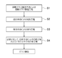
- FIG. 6 is a flowchart showing an embodiment of the glass product manufacturing method of the embodiment.
- the forming step (S2) by the forming means and the slow cooling step (S3) by the slow cooling means, which are components of the glass product manufacturing method, further necessary
- the cutting process used according to this and other post-process (S4) are shown.
- the glass melt G melted in the melting tank 12 of FIGS. 1 to 5 is sent to a molding means through an outlet and a conduit structure (not shown) and molded (molding process).
- the glass after molding is slowly cooled by a slow cooling means (gradual cooling process) so that no residual stress remains in the solidified glass after molding (further cooling process), and further cut (cutting process) as necessary. After that, it becomes a glass product.
- molding process (S2), a slow cooling process (S3), a cutting process, and another post-process (S4) what kind of process may be sufficient in the range which can achieve the objective.
- the glass melt G is formed into a glass ribbon by a forming means, and is slowly cooled by a slow cooling means, then cut to a desired size, and the glass end is polished as necessary.
- Sheet glass is obtained by post-processing such as.
- the molten glass produced by the molten glass production method of the present invention is not limited in terms of composition as long as it is a molten glass produced by an in-air heating melting method. Therefore, it may be soda lime glass or borosilicate glass. Moreover, the use of the manufactured glass product is not limited to architectural use or vehicle use, and examples include flat panel display use and other various uses.
- soda lime glass used for building or vehicle sheet glass it is expressed in terms of mass percentage based on oxide, SiO 2 : 65 to 75%, Al 2 O 3 : 0 to 3%, CaO: 5 to 15%, MgO: 0 to 15%, Na 2 O: 10 to 20%, K 2 O: 0 to 3%, Li 2 O: 0 to 5%, Fe 2 O 3 : 0 to 3%, TiO 2 : 0 to 5%, CeO 2 : 0 to 3%, BaO: 0 to 5%, SrO: 0 to 5%, B 2 O 3 : 0 to 5%, ZnO: 0 to 5%, ZrO 2 : 0 to 5 %, SnO 2 : 0 to 3%, SO 3 : 0 to 0.5%.
- SiO 2 39 to 70%
- Al 2 O 3 3 to 25%
- B 2 O 3 1 to 20%
- SrO: 0 to 20% BaO: 0 to 30% are preferable.
- a mixed alkali glass used for a substrate for a plasma display it is expressed in terms of mass percentage based on oxide, and SiO 2 : 50 to 75%, Al 2 O 3 : 0 to 15%, MgO + CaO + SrO + BaO + ZnO: 6 to 24 %, Na 2 O + K 2 O: preferably 6 to 24%.
- the molten glass produced by the present invention is molded into glass products of various shapes by molding means such as a float bath, a fusion molding machine, a roll-out molding machine, a blow molding machine, and a press molding machine. It should be noted that the entire contents of the specification, claims, drawings and abstract of Japanese Patent Application No. 2009-188348 filed on August 17, 2009 are cited here as disclosure of the specification of the present invention. Incorporated.
- F flame, G ... molten glass, 10 ... glass melting furnace, 12 ... melting tank, 14 ... upstream side wall surface, 16 ... glass raw material particle heating unit (heating means for forming glass raw material particle charging part and gas phase part), DESCRIPTION OF SYMBOLS 18 ... Ceiling wall, 20 ... Oxyfuel combustion burner, 20A-20H ... Oxyfuel combustion burner, 22 ... Nozzle, 26 ... Liquid glass particle, 28 ... Spherical bearing, 30 ... Suction area, 32 ... Gear, 34 ... Spherical bearing, 36 DESCRIPTION OF SYMBOLS ... Gear, 38 ... Motor, 40 ... Control part, 50 ... Glass melting furnace, 52 ... Oxygen combustion burner, 54 ... Nozzle, 56 ... Straight pipe part, 58 ... Bearing, 60 ... Gear, 62 ... Gear, 64 ... Motor, 70: Glass melting furnace, 72: Control unit
Abstract
Description
ガラス原料粒子が液状ガラス粒子となるときに発生する分解ガス成分は、ガラス原料粒子と液状ガラス粒子がともに小さな粒子であることより、生成する液状ガラス粒子の内部に閉じ込められることなくそのほとんどが液状ガラス粒子外部に放出される。このため、液状ガラス粒子が集積したガラス融液中に泡が生じるおそれは少ない。
一方、各ガラス原料粒子は、構成原料成分がほぼ均一な粒子であり、それから生じる各液状ガラス粒子のガラス組成も相互に均一である。液状ガラス粒子間のガラス組成の相違が少ないことより、多数の液状ガラス粒子が堆積して形成されるガラス融液内に、ガラス組成が異なる部分が生じるおそれは少ない。このため、従来のガラス溶融炉に必要とされていたガラス融液のガラス組成を均質化するための均質化手段が、気中溶融法ではほとんど必要とされない。たとえ少数の液状ガラス粒子が他の大部分の液状ガラス粒子とガラス組成が異なる場合が生じたとしても、液状ガラス粒子は粒径の小さな粒子であることより、ガラス組成が異なる少数の液状ガラス粒子から生じた、ガラス融液中のガラス組成の異質領域は小さく、この異質領域は短時間で容易に均質化して消失する。このように、気中溶融法ではガラス融液の均質化に必要とする熱エネルギーを低減し、均質化に要する時間を短くすることができる。 By the way, the glass raw material particles introduced from the glass raw material particle introduction part are generally made of a mixture of glass raw materials and granulated to have a particle size of 1 mm or less. The glass raw material particles put into the glass melting furnace are melted into liquid glass particles while descending (flying) in a high-temperature gas phase atmosphere, and the liquid glass particles fall downward to form glass. Accumulate at the bottom of the melting furnace to form a glass melt. The liquid glass particles generated from the glass raw material particles can also be expressed as glass droplets. In order to generate liquid glass particles from glass raw material particles in a high temperature gas phase atmosphere in a short time, the particle size of the glass raw material particles needs to be small as described above. In a normal case, the individual liquid glass particles generated from the individual glass raw material particles need to be particles having substantially the same glass composition.
The decomposition gas components generated when the glass raw material particles become liquid glass particles are mostly liquid without being confined inside the generated liquid glass particles because both the glass raw material particles and the liquid glass particles are small particles. Released outside the glass particles. For this reason, there is little possibility that a bubble will arise in the glass melt which liquid glass particles accumulated.
On the other hand, each glass raw material particle is a particle having substantially uniform constituent raw material components, and the glass composition of each liquid glass particle generated therefrom is also uniform. Since there is little difference in the glass composition between the liquid glass particles, there is little possibility that a portion having a different glass composition is generated in the glass melt formed by depositing a large number of liquid glass particles. For this reason, the homogenizing means for homogenizing the glass composition of the glass melt required for the conventional glass melting furnace is hardly required in the air melting method. Even if a small number of liquid glass particles have a glass composition different from that of most other liquid glass particles, the liquid glass particles are a small particle size, so a small number of liquid glass particles having a different glass composition. Thus, the heterogeneous region of the glass composition in the glass melt is small, and this heterogeneous region is easily homogenized and disappears in a short time. Thus, in the air melting method, the heat energy required for homogenization of the glass melt can be reduced, and the time required for homogenization can be shortened.
なお、液状ガラス粒子がガラス融液表面に接触した際に生成する泡としては、発生確率は低いと考えられるが、高温の気相雰囲気で溶融直後の液状ガラス粒子自体に残存した溶存ガス等があった場合に、その溶存ガス等を含む液状ガラス粒子がガラス融液に接触してガラス融液と一体化する直前や直後のその液状ガラス粒子部分に他の液状ガラス粒子が積み重なり、液状ガラス粒子に含まれていた溶存ガス等が閉じ込められて泡となることもある。 However, when liquid glass particles are continuously deposited at the same position on the surface of the glass melt, a gas such as air existing in the glass melting furnace is entrained in the liquid glass particles or the glass melt to generate bubbles. There was a fear. The bubbles generated when the liquid glass particles are deposited are bubbles generated by entraining a gas such as air or combustion gas between the liquid glass particles or between the liquid glass particles and the glass melt. For example, before the substantially spherical liquid glass particles in contact with the glass melt surface are integrated with the glass melt and flattened, another liquid glass particle falls on the liquid glass particles before the flattening. Gases such as air may come into contact with each other between the two liquid glass particles or between the two liquid glass particles and the glass melt surface.
In addition, it is considered that the probability of occurrence of bubbles generated when the liquid glass particles come into contact with the surface of the glass melt is low, but dissolved gas remaining in the liquid glass particles themselves immediately after melting in a high-temperature gas phase atmosphere. If the liquid glass particles containing the dissolved gas etc. are in contact with the glass melt and integrated with the glass melt, other liquid glass particles are stacked on the liquid glass particle portion immediately before and after the liquid glass particles. The dissolved gas etc. contained in may be trapped and become bubbles.
ガラス融液面上の同一位置に再び液状ガラス粒子が落下するまでの時間間隔については、製造するガラスの組成やガラス原料の種類、ガラス原料粒子の投下量、加熱手段により形成される気相部の温度、その他の気中溶融の条件によって変化する。このため、例えばガラス融液面を適宜観察しながら、ガスが巻き込まれない最適な時間間隔を設定するか、又は観察結果に基づいて適宜時間間隔を変更してもよい。 According to the production method of the present invention, the liquid glass particles do not continuously land at the same position on the glass melt surface by changing the liquid landing position of the liquid glass particles on the glass melt surface over time. Therefore, it is possible to prevent a gas such as air from being involved in the glass melt at the liquid glass particle landing position. In addition, since liquid glass particles do not continuously adhere to the same position on the glass melt surface, it is easy to ensure the time required for defoaming even if air or dissolved gas is taken into the glass melt to form bubbles. It is possible to produce a high-quality molten glass with few bubbles.
Regarding the time interval until the liquid glass particles fall again at the same position on the surface of the glass melt, the composition of the glass to be produced, the type of the glass raw material, the dropped amount of the glass raw material particles, the gas phase part formed by the heating means Depending on the temperature and other conditions of melting in the air. For this reason, for example, while observing the glass melt surface as appropriate, an optimal time interval at which no gas is involved may be set, or the time interval may be changed as appropriate based on the observation result.
このように、気相部の位置を略水平方向に移動させることにより、移動する気相部中で形成された液状ガラス粒子の着液位置を経時的に変化させることができる。この場合、ガラス溶融炉内の上部の炉壁部から下向きに供給されるガラス原料粒子の気相部への投入位置は、気相部の移動に従って移動することが好ましい。また、加熱手段が燃焼ガス供給管と酸素管とガラス原料粒子供給管とが同軸で構成されている酸素燃焼バーナである場合、酸素燃焼バーナ出口(ノズル)から火炎にガラス原料粒子を投入することにより、移動する火炎(気相部)中にガラス原料粒子を投入することができる。 In the manufacturing method of this invention, it is preferable to move the said heating means to a substantially horizontal direction. By the movement of the heating means, the position of the gas phase portion formed by the heating means can be changed with time in the substantially horizontal direction. Even when the heating means is fixed, the position of the gas phase portion formed by the heating means can be changed with time in the substantially horizontal direction. For example, when the heating means is an oxyfuel burner in which a combustion gas supply pipe, an oxygen pipe, and a glass raw material particle supply pipe are configured coaxially, the outlet of the oxyfuel burner (nozzle) even if the oxyfuel burner body is fixed ) In the substantially horizontal direction, the position of the flame (gas phase portion) formed at the tip of the outlet (nozzle) can be changed over time in the substantially horizontal direction.
In this way, by moving the position of the gas phase portion in the substantially horizontal direction, the liquid landing position of the liquid glass particles formed in the moving gas phase portion can be changed over time. In this case, it is preferable that the charging position of the glass raw material particles, which are supplied downward from the upper furnace wall in the glass melting furnace, into the gas phase part moves as the gas phase part moves. When the heating means is an oxyfuel burner in which a combustion gas supply pipe, an oxygen pipe, and a glass raw material particle supply pipe are configured coaxially, glass raw material particles are introduced into the flame from the oxyfuel burner outlet (nozzle). Thus, glass raw material particles can be introduced into the moving flame (gas phase portion).
本発明の製造方法においては、上記のように、気相部を形成する加熱手段を水平方向の位置を違えて複数備え、前記各加熱手段を異なる時間に作動させることも好ましい。後述のように、ガラス原料粒子投入部と加熱手段は組になっていること(後述のガラス原料粒子加熱ユニット)が好ましい。このガラス原料粒子加熱ユニットを作動させることにより、ガラス原料粒子の気相部への投入と加熱手段による気相部の形成を同時に行うことができる。したがって、水平方向の位置を違えたガラス原料粒子加熱ユニットを複数設けて、それらを順次作動させることより、液状ガラス粒子の着液位置を経時的に変化させることができる。 Further, according to the production method of the present invention, a plurality of gas phase portions having different horizontal positions are provided, and glass raw material particles are charged into the gas phase portions in a predetermined order, that is, glass raw material particles are charged. A liquid glass formed in the gas phase portion into which the glass raw material particles are charged by forming the gas phase portion and the gas phase portion that is not charged and changing the gas phase portion into which the glass raw material particles are charged over time The liquid landing position of the particles can be changed over time. In this case, the gas phase portion at the time when the glass raw material particles are not charged may not be formed. That is, since the gas phase part is formed by the heating means, the gas phase part formed by the heating means is not operated by not operating the heating means for forming the gas phase part when the glass raw material particles are not charged. Can not be formed. When it is time to add the glass raw material particles, the heating means is operated to form a gas phase portion. Note that when the gas phase portion is not formed, the glass raw material particles are not supplied to the place.
In the production method of the present invention, as described above, it is also preferable to provide a plurality of heating means for forming the gas phase part at different positions in the horizontal direction, and to operate each of the heating means at different times. As will be described later, it is preferable that the glass raw material particle charging portion and the heating means are combined (a glass raw material particle heating unit described later). By operating this glass raw material particle heating unit, it is possible to simultaneously introduce the glass raw material particles into the gas phase portion and form the gas phase portion by the heating means. Therefore, by providing a plurality of glass raw material particle heating units having different horizontal positions and sequentially operating them, the liquid landing position of the liquid glass particles can be changed over time.
なお、ここでいうガラス溶融炉の上部の炉壁部とは、ガラス溶融炉の天井部及び天井部の内壁から1m以内の側壁の範囲をいう。 In order to achieve the above object, the present invention provides a glass melt by collecting glass raw material particles as liquid glass particles in a gas phase atmosphere in a glass melting furnace and collecting the liquid glass particles at the bottom of the glass melting furnace. A glass melting furnace for discharging the glass melt, wherein the glass raw material particle charging portion is disposed downward on the furnace wall portion in the upper portion of the glass melting furnace, and the glass raw material particles are disposed below the glass raw material particle charging portion. Heating means for forming a gas phase part with liquid glass particles, moving means for moving the gas phase part in a substantially horizontal direction, a furnace bottom part for accumulating the liquid glass particles to form a glass melt, and There is provided a glass melting furnace comprising a discharge unit for discharging the glass melt.
In addition, the furnace wall part of the upper part of a glass melting furnace here means the range of the side wall within 1 m from the ceiling part of a glass melting furnace, and the inner wall of a ceiling part.
このように、気相部を略水平方向に移動させる移動手段を用いることにより、移動する気相部中で形成された液状ガラス粒子の落下位置を経時的に変化させることができる。この場合、ガラス溶融炉内の上部の炉壁部に下向きに設置されたガラス原料粒子投入部は、気相部の移動に従って移動することが好ましい。また、加熱手段が燃焼ガス供給管と酸素管とガラス原料粒子供給管とが同軸で構成されている酸素燃焼バーナである場合は、酸素燃焼バーナの出口(ノズル)とガラス原料粒子投入部の出口が一体であることより、移動手段により移動する火炎(気相部)中にガラス原料粒子を投入することができる。 The moving means of the gas phase part is preferably a moving means for moving the heating means in a substantially horizontal direction. Further, the moving means is preferably a moving means that changes the position of the gas phase formed by the heating means in a substantially horizontal direction over time even when the heating means is fixed. For example, when the heating means is an oxyfuel combustion burner in which a combustion gas supply pipe, an oxygen pipe, and a glass raw material particle supply pipe are configured coaxially, even if the oxyfuel combustion burner body is fixed, the outlet of the oxyfuel combustion burner (nozzle) ) In the substantially horizontal direction, the position of the flame (gas phase part) formed at the tip of the outlet (nozzle) of the burner can be changed over time in the substantially horizontal direction.
In this way, by using the moving means for moving the gas phase portion in the substantially horizontal direction, the dropping position of the liquid glass particles formed in the moving gas phase portion can be changed over time. In this case, it is preferable that the glass raw material particle charging portion installed downward on the upper furnace wall in the glass melting furnace moves according to the movement of the gas phase portion. Further, when the heating means is an oxyfuel combustion burner in which a combustion gas supply pipe, an oxygen pipe and a glass raw material particle supply pipe are configured coaxially, an outlet (nozzle) of the oxyfuel combustion burner and an outlet of the glass raw material particle charging section Since these are integrated, glass raw material particles can be introduced into a flame (gas phase portion) that is moved by the moving means.
なお、ここでいうガラス溶融炉の上部の炉壁部とは、ガラス溶融炉の天井部及び天井部の内壁から1m以内の側壁の範囲をいう。 Furthermore, in order to achieve the above object, the present invention provides glass raw material particles as liquid glass particles in a gas-phase atmosphere in a glass melting furnace, and the liquid glass particles are accumulated at the bottom of the glass melting furnace. A glass melting furnace for discharging the glass melt, wherein the glass raw material particle charging portion is disposed downward on the furnace wall portion in the upper portion of the glass melting furnace, and the glass raw material particles are disposed below the glass raw material particle charging portion. A heating means for forming a gas phase part having a liquid glass particle, a plurality of sets of the glass raw material particle charging part and the heating means are provided in a substantially horizontal direction, and the plurality of sets are operated at different times. There is provided a glass melting furnace comprising an operation control unit, a furnace bottom part for accumulating the liquid glass particles to form a glass melt, and a discharge part for discharging the glass melt.
In addition, the furnace wall part of the upper part of a glass melting furnace here means the range of the side wall within 1 m from the ceiling part of a glass melting furnace, and the inner wall of a ceiling part.
本発明によれば、酸素燃焼バーナによる酸素燃焼炎の場合には約2000℃の高温の気相雰囲気を形成でき、熱プラズマの場合には5000~20000℃の高温の気相雰囲気を形成できる。よって、その高温の気相雰囲気内で降下するガラス原料粒子を短時間で溶融し、液状ガラス粒子とすることができる。なお、酸素燃焼バーナ及び多相アークプラズマ発生装置は、単独で設置してもよく双方を併用してもよい。なお、加熱手段として使用される酸素燃焼バーナとしては、ガラス原料粒子投入部が一体となった形態のバーナを使用することができる。 The method for producing a molten glass of the present invention or the heating means in the melting furnace is at least one of an oxyfuel burner for generating an oxyfuel flame and a multiphase arc plasma generator comprising a pair of electrodes for generating thermal plasma. One is preferable.
According to the present invention, a high-temperature gas phase atmosphere of about 2000 ° C. can be formed in the case of an oxyfuel flame using an oxyfuel burner, and a high-temperature gas phase atmosphere of 5000 to 20000 ° C. can be formed in the case of thermal plasma. Therefore, the glass raw material particles falling in the high-temperature gas phase atmosphere can be melted in a short time to form liquid glass particles. The oxyfuel burner and the multiphase arc plasma generator may be installed alone or in combination. In addition, as an oxygen combustion burner used as a heating means, a burner having a form in which a glass raw material particle charging unit is integrated can be used.
図示したガラス溶融炉において、気相部を形成する加熱手段は酸素燃焼バーナからなる。気相部は、酸素燃焼バーナの火炎中及び火炎近傍の高温部から構成される。
気相部にガラス原料粒子を供給するためのガラス原料粒子投入部は酸素燃焼バーナと一体となり、酸素燃焼バーナ出口付近で燃焼ガスを供給する管と酸素を供給する管とガラス原料粒子を供給する管が同軸で構成されている。このガラス原料粒子投入部と酸素燃焼バーナとの組み合わせを、ガラス原料粒子加熱ユニットという。 Preferred embodiments of a molten glass production method, a glass melting furnace, a glass product production method, and a glass product production apparatus according to the present invention will be described below with reference to the accompanying drawings.
In the illustrated glass melting furnace, the heating means for forming the gas phase portion is composed of an oxyfuel combustion burner. The gas phase part is composed of a high temperature part in the flame of the oxyfuel burner and in the vicinity of the flame.
The glass raw material particle input part for supplying glass raw material particles to the gas phase part is integrated with the oxyfuel burner, and a tube for supplying combustion gas, a tube for supplying oxygen and a glass raw material particle are supplied near the outlet of the oxyfuel burner. The tube is coaxial. The combination of the glass raw material particle charging portion and the oxyfuel combustion burner is referred to as a glass raw material particle heating unit.
ガラス原料粒子の平均粒径(重量平均)は30~1000μmが好ましい。より好ましくは、平均粒径(重量平均)が50~500μmの範囲内のガラス原料粒子が使用され、さらに70~300μmの範囲内のガラス原料粒子が好ましい。ガラス原料粒子が溶融した液状ガラス粒子の平均粒径(重量平均)は、通常ガラス原料粒子の平均粒径の80%程度となることが多い。
図中、火炎Fの内部やその下方に描いた粒子26は、ガラス原料粒子が液状ガラス粒子となる途中の粒子や液状ガラス粒子を示す。ガラス原料粒子は火炎F中で迅速に液状ガラス粒子となると考えられるので、以下この粒子を液状ガラス粒子26ともいう。 As a result, the glass raw material particles dropped in the furnace are rapidly gasified and gasified by being heated to high temperature in the flame F or thermal plasma to become liquid glass particles, and the generated liquid glass particles are melted. The glass melt G is landed and accumulated on the bottom of the
The average particle diameter (weight average) of the glass raw material particles is preferably 30 to 1000 μm. More preferably, glass raw material particles having an average particle diameter (weight average) in the range of 50 to 500 μm are used, and glass raw material particles in the range of 70 to 300 μm are more preferable. The average particle size (weight average) of the liquid glass particles in which the glass material particles are melted is usually about 80% of the average particle size of the glass material particles in many cases.
In the figure,
火炎Fが水平面上で円を描いて移動するに伴い、火炎F中で形成された液状ガラス粒子26は鉛直軸Oを中心とする円周に沿って落下し、その下方のガラス融液Gの表面に着液する。すなわち、液状ガラス粒子26のガラス融液面上の着液位置は、図1の二点鎖線で示すドーナツ状の着液エリア30内で経時的に変化する。 Meanwhile, the
As the flame F moves while drawing a circle on the horizontal plane, the
なお、2009年8月17日に出願された日本特許出願2009-188348号の明細書、特許請求の範囲、図面及び要約書の全内容をここに引用し、本発明の明細書の開示として、取り入れるものである。 The molten glass produced by the present invention is molded into glass products of various shapes by molding means such as a float bath, a fusion molding machine, a roll-out molding machine, a blow molding machine, and a press molding machine.
It should be noted that the entire contents of the specification, claims, drawings and abstract of Japanese Patent Application No. 2009-188348 filed on August 17, 2009 are cited here as disclosure of the specification of the present invention. Incorporated.
Claims (13)
- ガラス溶融炉内の気相雰囲気中でガラス原料粒子を液状ガラス粒子とし、該液状ガラス粒子をガラス溶融炉の底部に集積してガラス融液とする溶融ガラスの製造方法であって、
前記ガラス原料粒子を、前記ガラス溶融炉内の上部の炉壁部から下向きに供給し、加熱手段により形成された気相部を通過させて液状ガラス粒子とし、
前記気相部の位置を略水平方向に経時的に変化させて、当該気相部中で形成された前記液状ガラス粒子のガラス融液面上の着液位置を経時的に変化させることを特徴とする溶融ガラスの製造方法。 In a gas phase atmosphere in a glass melting furnace, glass raw material particles are made into liquid glass particles, and the liquid glass particles are accumulated at the bottom of the glass melting furnace to make a glass melt,
The glass raw material particles are supplied downward from the upper furnace wall in the glass melting furnace, and passed through the gas phase part formed by the heating means to form liquid glass particles,
The position of the gas phase part is changed over time in a substantially horizontal direction, and the liquid landing position on the glass melt surface of the liquid glass particles formed in the gas phase part is changed over time. A method for producing molten glass. - 前記加熱手段は、酸素燃焼炎を発生させる酸素燃焼バーナ、及び熱プラズマを発生させる一対以上の電極で構成される多相アークプラズマ発生装置のうち少なくとも一つである、請求項1に記載の溶融ガラスの製造方法。 2. The melting according to claim 1, wherein the heating means is at least one of an oxyfuel burner that generates an oxyfuel flame and a multiphase arc plasma generator that includes a pair of electrodes that generate thermal plasma. Glass manufacturing method.
- 前記加熱手段を略水平方向に移動させる、請求項1又は2に記載の溶融ガラスの製造方法。 The method for producing molten glass according to claim 1 or 2, wherein the heating means is moved in a substantially horizontal direction.
- 前記加熱手段は燃焼ガス供給管と酸素管とガラス原料粒子供給管とが同軸で構成されている酸素燃焼バーナであり、前記酸素燃焼バーナの出口を略水平方向に移動させる、請求項1乃至3のいずれか一項に記載の溶融ガラスの製造方法。 The heating means is an oxyfuel combustion burner in which a combustion gas supply pipe, an oxygen pipe, and a glass raw material particle supply pipe are configured coaxially, and the outlet of the oxyfuel combustion burner is moved in a substantially horizontal direction. The manufacturing method of the molten glass as described in any one of these.
- 前記気相部を形成する加熱手段を水平方向の位置を違えて複数備え、前記各加熱手段を異なる時間に作動させる、請求項1又は2に記載の溶融ガラスの製造方法。 The method for producing molten glass according to claim 1 or 2, wherein a plurality of heating means for forming the gas phase part are provided at different positions in the horizontal direction, and the heating means are operated at different times.
- 請求項1乃至5のいずれか一項に記載の溶融ガラスの製造方法により溶融ガラスを製造する工程と、該溶融ガラスを成形する工程と、成形後のガラスを徐冷する工程とを含むことを特徴とするガラス製品の製造方法。 The method of manufacturing a molten glass by the manufacturing method of the molten glass as described in any one of Claims 1 thru | or 5, including the process of shape | molding this molten glass, and the process of slowly cooling the glass after shaping | molding. The manufacturing method of the glass product characterized.
- ガラス溶融炉内の気相雰囲気中でガラス原料粒子を液状ガラス粒子とし、該液状ガラス粒子をガラス溶融炉の底部に集積してガラス融液とし、該ガラス融液を排出するガラス溶融炉であって、
前記ガラス溶融炉内の上部の炉壁部に下向きに設置されたガラス原料粒子投入部、
前記ガラス原料粒子投入部下方にガラス原料粒子を液状ガラス粒子とする気相部を形成するための加熱手段、
前記気相部を略水平方向に移動させる移動手段、
前記液状ガラス粒子を集積してガラス融液を形成する炉底部、および、
前記ガラス融液を排出する排出部、
を備えたことを特徴とするガラス溶融炉。 A glass melting furnace in which glass raw material particles are made into liquid glass particles in a gas phase atmosphere in a glass melting furnace, the liquid glass particles are accumulated at the bottom of the glass melting furnace to form a glass melt, and the glass melt is discharged. And
Glass raw material particle charging unit installed downward on the upper furnace wall in the glass melting furnace,
A heating means for forming a gas phase part having the glass raw material particles as liquid glass particles below the glass raw material particle charging part,
Moving means for moving the gas phase portion in a substantially horizontal direction;
A furnace bottom part that accumulates the liquid glass particles to form a glass melt, and
A discharge part for discharging the glass melt;
A glass melting furnace comprising: - 前記加熱手段は、酸素燃焼炎を発生させる酸素燃焼バーナ、及び熱プラズマを発生させる一対以上の電極で構成される多相アークプラズマ発生装置のうち少なくとも一つである、請求項7に記載のガラス溶融炉。 The glass according to claim 7, wherein the heating means is at least one of an oxyfuel burner that generates an oxyfuel flame and a multiphase arc plasma generator that includes a pair of electrodes that generate thermal plasma. Melting furnace.
- 前記移動手段は、加熱手段を略水平方向に移動させる移動手段である、請求項7又は8に記載のガラス溶融炉。 The glass melting furnace according to claim 7 or 8, wherein the moving means is a moving means for moving the heating means in a substantially horizontal direction.
- 前記加熱手段は燃焼ガス供給管と酸素管とガラス原料粒子供給管とが同軸で構成されている酸素燃焼バーナであり、前記移動手段は前記酸素燃焼バーナの出口を略水平方向に移動させる移動手段である、請求項7乃至9のいずれか一項に記載のガラス溶融炉。 The heating means is an oxyfuel combustion burner in which a combustion gas supply pipe, an oxygen pipe, and a glass raw material particle supply pipe are configured coaxially, and the moving means moves the outlet of the oxyfuel combustion burner in a substantially horizontal direction. The glass melting furnace as described in any one of Claims 7 thru | or 9 which is.
- ガラス溶融炉内の気相雰囲気中でガラス原料粒子を液状ガラス粒子とし、該液状ガラス粒子をガラス溶融炉の底部に集積してガラス融液とし、該ガラス融液を排出するガラス溶融炉であって、
前記ガラス溶融炉内の上部の炉壁部に下向きに設置されたガラス原料粒子投入部、
前記ガラス原料粒子投入部下方にガラス原料粒子を液状ガラス粒子とする気相部を形成するための加熱手段、
前記ガラス原料粒子投入部と前記加熱手段の組を略水平方向に複数備えること、
前記複数の組を異なる時間に作動させるための作動制御部、
前記液状ガラス粒子を集積してガラス融液を形成する炉底部、および、
前記ガラス融液を排出する排出部、
を備えたことを特徴とするガラス溶融炉。 A glass melting furnace in which glass raw material particles are made into liquid glass particles in a gas phase atmosphere in a glass melting furnace, the liquid glass particles are accumulated at the bottom of the glass melting furnace to form a glass melt, and the glass melt is discharged. And
Glass raw material particle charging unit installed downward on the upper furnace wall in the glass melting furnace,
A heating means for forming a gas phase part having the glass raw material particles as liquid glass particles below the glass raw material particle charging part,
Comprising a plurality of sets of the glass raw material particle charging part and the heating means in a substantially horizontal direction;
An operation control unit for operating the plurality of sets at different times;
A furnace bottom part that accumulates the liquid glass particles to form a glass melt, and
A discharge part for discharging the glass melt;
A glass melting furnace comprising: - 前記加熱手段は、酸素燃焼炎を発生させる酸素燃焼バーナ、及び熱プラズマを発生させる一対以上の電極で構成される多相アークプラズマ発生装置のうち少なくとも一つである、請求項11に記載のガラス溶融炉。 The glass according to claim 11, wherein the heating means is at least one of an oxyfuel burner that generates an oxyfuel flame and a multiphase arc plasma generator that includes a pair of electrodes that generate thermal plasma. Melting furnace.
- 請求項7乃至12のいずれか一項に記載のガラス溶融炉と、該ガラス溶融炉の前記排出部の下流側に設けられた溶融ガラスを成形する成形手段と、成形後のガラスを徐冷する徐冷手段とを備えたことを特徴とするガラス製品の製造装置。 A glass melting furnace according to any one of claims 7 to 12, a forming means for forming molten glass provided on the downstream side of the discharge part of the glass melting furnace, and the glass after forming is gradually cooled. An apparatus for producing glass products, comprising a slow cooling means.
Priority Applications (5)
| Application Number | Priority Date | Filing Date | Title |
|---|---|---|---|
| EP10809920.1A EP2468688A4 (en) | 2009-08-17 | 2010-08-12 | Molten glass manufacturing method, glass-melting furnace, glass product manufacturing method, and glass product manufacturing device |
| JP2011527657A JP5614407B2 (en) | 2009-08-17 | 2010-08-12 | Molten glass manufacturing method, glass melting furnace, glass product manufacturing method, and glass product manufacturing apparatus |
| KR1020117027867A KR101807320B1 (en) | 2009-08-17 | 2010-08-12 | Molten glass manufacturing method, glass-melting furnace, glass product manufacturing method, and glass product manufacturing device |
| CN201080037043.7A CN102482131B (en) | 2009-08-17 | 2010-08-12 | Molten glass manufacturing method, glass-melting furnace, glass product manufacturing method, and glass product manufacturing device |
| US13/370,820 US8573007B2 (en) | 2009-08-17 | 2012-02-10 | Process for producing molten glass, glass-melting furnace, process for producing glass products and apparatus for producing glass products |
Applications Claiming Priority (2)
| Application Number | Priority Date | Filing Date | Title |
|---|---|---|---|
| JP2009-188348 | 2009-08-17 | ||
| JP2009188348 | 2009-08-17 |
Related Child Applications (1)
| Application Number | Title | Priority Date | Filing Date |
|---|---|---|---|
| US13/370,820 Continuation US8573007B2 (en) | 2009-08-17 | 2012-02-10 | Process for producing molten glass, glass-melting furnace, process for producing glass products and apparatus for producing glass products |
Publications (1)
| Publication Number | Publication Date |
|---|---|
| WO2011021575A1 true WO2011021575A1 (en) | 2011-02-24 |
Family
ID=43607030
Family Applications (1)
| Application Number | Title | Priority Date | Filing Date |
|---|---|---|---|
| PCT/JP2010/063722 WO2011021575A1 (en) | 2009-08-17 | 2010-08-12 | Molten glass manufacturing method, glass-melting furnace, glass product manufacturing method, and glass product manufacturing device |
Country Status (7)
| Country | Link |
|---|---|
| US (1) | US8573007B2 (en) |
| EP (1) | EP2468688A4 (en) |
| JP (1) | JP5614407B2 (en) |
| KR (1) | KR101807320B1 (en) |
| CN (1) | CN102482131B (en) |
| TW (1) | TW201119960A (en) |
| WO (1) | WO2011021575A1 (en) |
Families Citing this family (14)
| Publication number | Priority date | Publication date | Assignee | Title |
|---|---|---|---|---|
| JP5585581B2 (en) * | 2009-07-01 | 2014-09-10 | 旭硝子株式会社 | Glass melting furnace, molten glass manufacturing method, glass product manufacturing apparatus, and glass product manufacturing method |
| EP2452925A4 (en) * | 2009-07-08 | 2014-03-26 | Asahi Glass Co Ltd | Glass melting furnace, molten glass manufacturing method, glass product manufacturing device, and glass product manufacturing method |
| WO2011021576A1 (en) * | 2009-08-20 | 2011-02-24 | 旭硝子株式会社 | Glass melting furnace, molten glass producing method, glass product producing device, and glass product producing method |
| CN102648163B (en) | 2009-11-20 | 2015-11-25 | 旭硝子株式会社 | The manufacture method of the manufacture method of glass melting furnace, melten glass, the manufacturing installation of glasswork and glasswork |
| WO2011102391A1 (en) * | 2010-02-19 | 2011-08-25 | 日本山村硝子株式会社 | Method for monitoring glass melting furnace, method for controlling introduction of raw material, and device for controlling introduction of raw material |
| US9346696B2 (en) * | 2012-07-02 | 2016-05-24 | Glass Strand Inc. | Glass-melting furnace burner and method of its use |
| BR102012027523A2 (en) * | 2012-10-26 | 2014-10-21 | Astc Tecnologia Ltda | COMBUSTION SYSTEM FOR COATING MANUFACTURING |
| US9518734B2 (en) | 2013-01-28 | 2016-12-13 | General Electric Technology Gmbh | Fluid distribution and mixing grid for mixing gases |
| US20140309099A1 (en) | 2013-04-15 | 2014-10-16 | Ppg Industries Ohio, Inc. | Low iron, high redox ratio, and high iron, high redox ratio, soda-lime-silica glasses and methods of making same |
| US20160200618A1 (en) * | 2015-01-08 | 2016-07-14 | Corning Incorporated | Method and apparatus for adding thermal energy to a glass melt |
| US10337732B2 (en) * | 2016-08-25 | 2019-07-02 | Johns Manville | Consumable tip burners, submerged combustion melters including same, and methods |
| US11912608B2 (en) | 2019-10-01 | 2024-02-27 | Owens-Brockway Glass Container Inc. | Glass manufacturing |
| KR20210081554A (en) * | 2019-12-24 | 2021-07-02 | 코닝 인코포레이티드 | Glass manufacturing apparatus and methods for processing a molten material |
| CN113461312B (en) * | 2021-07-05 | 2022-07-15 | 巨石集团有限公司 | Rotary combustion method of kiln |
Citations (3)
| Publication number | Priority date | Publication date | Assignee | Title |
|---|---|---|---|---|
| JP2006199549A (en) * | 2005-01-21 | 2006-08-03 | Tokyo Institute Of Technology | Method and apparatus for dissolving glass material and glass production apparatus |
| JP2007297239A (en) * | 2006-04-28 | 2007-11-15 | Tokyo Institute Of Technology | Method and apparatus for dissolving glass raw material and glass production apparatus |
| JP2009188348A (en) | 2008-02-08 | 2009-08-20 | Tokyo Electron Ltd | Method for forming insulating film, computer readable storage medium, and processing system |
Family Cites Families (11)
| Publication number | Priority date | Publication date | Assignee | Title |
|---|---|---|---|---|
| FR746004A (en) * | 1932-02-05 | 1933-05-20 | Saint Gobain | Process and devices for manufacturing vitreous products by stretching or rolling |
| US3337324A (en) * | 1963-04-30 | 1967-08-22 | Union Carbide Corp | Process for melting and refining glass batch |
| US3980460A (en) * | 1974-05-02 | 1976-09-14 | Owens-Corning Fiberglas Corporation | Feeder for glass melting furnaces |
| US3929445A (en) * | 1974-07-05 | 1975-12-30 | Alfred Zippe | Mixture feeder for continuous electric glass-melting furnace |
| US4381934A (en) * | 1981-07-30 | 1983-05-03 | Ppg Industries, Inc. | Glass batch liquefaction |
| JPS596253A (en) | 1982-07-02 | 1984-01-13 | Daicel Chem Ind Ltd | Heat- and impact-resistant resin composition |
| GB8321525D0 (en) * | 1983-08-10 | 1983-09-14 | Rockware Group Plc | Glass articles |
| US5579705A (en) * | 1993-03-08 | 1996-12-03 | Kabushiki Kaisha Kobe Seiko Sho | Plasma furnace and a method of operating the same |
| JP2007153676A (en) * | 2005-12-06 | 2007-06-21 | Daido Steel Co Ltd | Premelting method for glass raw material |
| JPWO2007129509A1 (en) | 2006-05-01 | 2009-09-17 | 旭硝子株式会社 | Glass manufacturing method |
| CN201058846Y (en) * | 2007-04-10 | 2008-05-14 | 江苏九鼎新材料股份有限公司 | Scattering device for all-electric hexagon glass-fiber fermentation pit |
-
2010
- 2010-08-12 JP JP2011527657A patent/JP5614407B2/en not_active Expired - Fee Related
- 2010-08-12 WO PCT/JP2010/063722 patent/WO2011021575A1/en active Application Filing
- 2010-08-12 KR KR1020117027867A patent/KR101807320B1/en active IP Right Grant
- 2010-08-12 EP EP10809920.1A patent/EP2468688A4/en not_active Withdrawn
- 2010-08-12 CN CN201080037043.7A patent/CN102482131B/en not_active Expired - Fee Related
- 2010-08-16 TW TW099127277A patent/TW201119960A/en unknown
-
2012
- 2012-02-10 US US13/370,820 patent/US8573007B2/en not_active Expired - Fee Related
Patent Citations (3)
| Publication number | Priority date | Publication date | Assignee | Title |
|---|---|---|---|---|
| JP2006199549A (en) * | 2005-01-21 | 2006-08-03 | Tokyo Institute Of Technology | Method and apparatus for dissolving glass material and glass production apparatus |
| JP2007297239A (en) * | 2006-04-28 | 2007-11-15 | Tokyo Institute Of Technology | Method and apparatus for dissolving glass raw material and glass production apparatus |
| JP2009188348A (en) | 2008-02-08 | 2009-08-20 | Tokyo Electron Ltd | Method for forming insulating film, computer readable storage medium, and processing system |
Non-Patent Citations (1)
| Title |
|---|
| See also references of EP2468688A4 |
Also Published As
| Publication number | Publication date |
|---|---|
| TW201119960A (en) | 2011-06-16 |
| JP5614407B2 (en) | 2014-10-29 |
| EP2468688A4 (en) | 2014-03-26 |
| EP2468688A1 (en) | 2012-06-27 |
| KR20120038927A (en) | 2012-04-24 |
| KR101807320B1 (en) | 2017-12-08 |
| US20120137737A1 (en) | 2012-06-07 |
| CN102482131B (en) | 2014-10-08 |
| JPWO2011021575A1 (en) | 2013-01-24 |
| US8573007B2 (en) | 2013-11-05 |
| CN102482131A (en) | 2012-05-30 |
Similar Documents
| Publication | Publication Date | Title |
|---|---|---|
| JP5614407B2 (en) | Molten glass manufacturing method, glass melting furnace, glass product manufacturing method, and glass product manufacturing apparatus | |
| JP5605767B2 (en) | Glass melting furnace, molten glass manufacturing method, glass product manufacturing apparatus, and glass product manufacturing method | |
| JP5674156B2 (en) | Glass melting furnace, molten glass manufacturing method, glass product manufacturing apparatus, and glass product manufacturing method | |
| JP5585581B2 (en) | Glass melting furnace, molten glass manufacturing method, glass product manufacturing apparatus, and glass product manufacturing method | |
| JP5664872B2 (en) | Molten glass manufacturing method, glass melting furnace, glass product manufacturing apparatus, and glass product manufacturing method | |
| CN102482132B (en) | Glass melting furnace, molten glass producing method, glass product producing device, and glass product producing method | |
| JP5717054B2 (en) | Glass melting furnace, molten glass manufacturing method, glass product manufacturing apparatus, and glass product manufacturing method | |
| KR101965003B1 (en) | Method for producing molten glass, glass-melting furnace, method for producing glass article, and device for producing glass article | |
| JP6032201B2 (en) | Glass melting furnace, molten glass manufacturing method, glass article manufacturing method, and glass article manufacturing apparatus |
Legal Events
| Date | Code | Title | Description |
|---|---|---|---|
| WWE | Wipo information: entry into national phase |
Ref document number: 201080037043.7 Country of ref document: CN |
|
| 121 | Ep: the epo has been informed by wipo that ep was designated in this application |
Ref document number: 10809920 Country of ref document: EP Kind code of ref document: A1 |
|
| ENP | Entry into the national phase |
Ref document number: 20117027867 Country of ref document: KR Kind code of ref document: A |
|
| WWE | Wipo information: entry into national phase |
Ref document number: 2011527657 Country of ref document: JP |
|
| REEP | Request for entry into the european phase |
Ref document number: 2010809920 Country of ref document: EP |
|
| WWE | Wipo information: entry into national phase |
Ref document number: 2010809920 Country of ref document: EP |
|
| NENP | Non-entry into the national phase |
Ref country code: DE |