以下、本発明の実施の形態について、図面を参照しながら説明する。
Hereinafter, embodiments of the present invention will be described with reference to the drawings.
(実施の形態1)
本発明の実施の形態1に係る符号化装置は、入力信号を変換することで、変換出力信号を生成する変換部と、変換出力信号を量子化することで、量子化係数を生成する量子化部と、量子化係数をエントロピー符号化することで、符号化信号を生成するエントロピー符号化部とを備える。そして、変換部は、第1変換係数で構成される第1変換行列を用いて入力信号に第1変換を行うことで、第1変換出力信号を生成する第1変換部と、第1変換出力信号の一部である第1部分信号に、第2変換係数で構成される第2変換行列を用いて第2変換を行うことで、第2変換出力信号を生成し、生成した第2変換出力信号と、第1変換出力信号のうち第1部分信号以外の部分である第2部分信号とを含む前記変換出力信号を出力する第2変換部とを備える。
(Embodiment 1)
The encoding apparatus according to Embodiment 1 of the present invention includes a conversion unit that generates a converted output signal by converting an input signal, and a quantization that generates a quantization coefficient by quantizing the converted output signal. And an entropy encoding unit that generates an encoded signal by entropy encoding the quantized coefficient. And a conversion part performs the 1st conversion to an input signal using the 1st conversion matrix constituted by the 1st conversion coefficient, and the 1st conversion part which generates the 1st conversion output signal, and the 1st conversion output A second conversion output signal is generated by performing a second conversion on the first partial signal, which is a part of the signal, using a second conversion matrix composed of the second conversion coefficient, and the generated second conversion output A second conversion unit that outputs the converted output signal including a signal and a second partial signal that is a portion other than the first partial signal of the first converted output signal.
言い換えると、本発明の実施の形態1に係る符号化装置は、入力信号に対して2段階の変換を行うことを特徴とする。具体的には、本発明の実施の形態1に係る符号化装置は、入力信号に第1変換を行い、第1変換後の信号の一部である第1部分信号に第2変換を行うことを特徴とする。
In other words, the encoding apparatus according to Embodiment 1 of the present invention is characterized by performing two-stage conversion on an input signal. Specifically, the encoding apparatus according to Embodiment 1 of the present invention performs first conversion on an input signal and performs second conversion on a first partial signal that is a part of the signal after the first conversion. It is characterized by.
なお、本明細書においては、変換行列と変換係数とはほぼ同義として用いる場合がある。
In this specification, the conversion matrix and the conversion coefficient may be used almost synonymously.
なお、バタフライ構成やシフトと加算の演算を用いる構成のように、単純な行列演算でなくとも実現できる変換であっても、本明細書では行列表現で記述する場合がある。このように行列表現で記述することは、バタフライ構成や、シフトと加算の演算を用いる構成、あるいは、リフティング構造を用いる構成など、各種の演算量を軽減した変換を除外するものではない。
Note that even in the present specification, even a conversion that can be realized without using a simple matrix operation, such as a butterfly configuration or a configuration using shift and addition operations, may be described in a matrix expression in this specification. Such description in matrix representation does not exclude transformations that reduce the amount of various calculations such as a butterfly configuration, a configuration using shift and addition operations, or a configuration using a lifting structure.
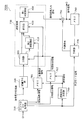
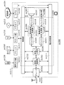
図3は、本発明の実施の形態1に係る符号化装置100の構成の一例を示すブロック図である。図3に示すように、符号化装置100は、変換部110と、量子化部120と、エントロピー符号化部130とを備える。
FIG. 3 is a block diagram showing an example of the configuration of encoding apparatus 100 according to Embodiment 1 of the present invention. As illustrated in FIG. 3, the encoding device 100 includes a conversion unit 110, a quantization unit 120, and an entropy encoding unit 130.
変換部110は、入力信号(変換入力信号)を変換することで、変換出力信号を生成する。変換部110は、図3に示すように、第1変換部200と、分割部210と、第2変換部220と、統合部230とを備える。
The conversion unit 110 generates a converted output signal by converting an input signal (converted input signal). As illustrated in FIG. 3, the conversion unit 110 includes a first conversion unit 200, a division unit 210, a second conversion unit 220, and an integration unit 230.
第1変換部200は、第1変換行列を用いて変換入力信号に第1変換を行うことで、第1変換出力信号を生成する。
The first converter 200 generates a first conversion output signal by performing a first conversion on the conversion input signal using the first conversion matrix.
分割部210は、第1変換出力信号を2つの部分に分割する。具体的には、分割部210は、第1変換部200によって生成された第1変換出力信号を、分割統合情報を用いて第1部分信号と第2部分信号とに分割する。なお、分割統合情報は、第1部分信号が第1変換出力信号のどの部分に対応するかを示す選択範囲情報の一例である。
The dividing unit 210 divides the first converted output signal into two parts. Specifically, the dividing unit 210 divides the first converted output signal generated by the first converting unit 200 into a first partial signal and a second partial signal using the division integration information. The division integration information is an example of selection range information indicating which part of the first converted output signal the first partial signal corresponds to.
第2変換部220は、第2変換行列を用いて第1部分信号に第2変換を行うことで、第2変換出力信号を生成する。
2nd conversion part 220 generates the 2nd conversion output signal by performing the 2nd conversion to the 1st partial signal using the 2nd conversion matrix.
統合部230は、第2変換出力信号と第2部分信号とを統合することで、変換出力信号を生成する。
The integrating unit 230 generates a converted output signal by integrating the second converted output signal and the second partial signal.
上記の変換部110が備える各処理部の詳細な動作については、後で説明する。
The detailed operation of each processing unit included in the conversion unit 110 will be described later.
量子化部120は、変換部110によって生成された変換出力信号を量子化することで、量子化係数を生成する。
The quantization unit 120 generates a quantization coefficient by quantizing the conversion output signal generated by the conversion unit 110.
エントロピー符号化部130は、量子化部120によって生成された量子化係数をエントロピー符号化することで、符号化信号を生成する。
The entropy encoding unit 130 generates an encoded signal by entropy encoding the quantization coefficient generated by the quantization unit 120.
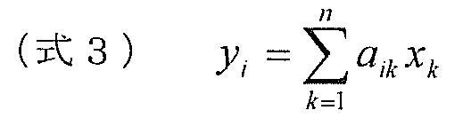
なお、符号化装置100には、音声データ、静止画像データ、動画像データなどの各種データである入力信号が符号化対象信号として入力される。変換部110には、符号化対象信号(Original Signal)、又は、この符号化対象信号と、以前に入力された符号化対象信号に基づいて作成された予測信号との差分である予測誤差信号が、変換入力信号として、入力される。一般的には、予測誤差信号が変換の対象として入力されることが多いが、伝送路にエラーが混入する場合を想定して予測を行わない場合、又は、エネルギーが小さい場合には、予測を行わずに入力信号が変換の対象として入力される。このような変換入力(Transform Input)信号を式4に示すようなベクトルxnと表す。
Note that an input signal, which is various data such as audio data, still image data, and moving image data, is input to the encoding device 100 as an encoding target signal. The conversion unit 110 has an encoding target signal (Original Signal) or a prediction error signal that is a difference between the encoding target signal and a prediction signal created based on the previously input encoding target signal. Are input as converted input signals. In general, a prediction error signal is often input as an object of conversion.However, when prediction is not performed assuming that an error is mixed in the transmission path, or when energy is small, prediction is performed. Instead, the input signal is input as a conversion target. Such a transform input signal is represented as a vector xn as shown in Equation 4.
続いて、本発明の実施の形態1に係る符号化装置100の動作の一例について説明する。
Subsequently, an example of the operation of the encoding apparatus 100 according to Embodiment 1 of the present invention will be described.
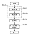
図4は、本発明の実施の形態1に係る符号化装置100の動作の一例を示すフローチャートである。また、図5A及び図5Bは、本発明の実施の形態1に係る符号化装置100における変換部110のデータフローの一例を概念的に示す図である。
FIG. 4 is a flowchart showing an example of the operation of the encoding apparatus 100 according to Embodiment 1 of the present invention. 5A and 5B are diagrams conceptually illustrating an example of the data flow of conversion section 110 in coding apparatus 100 according to Embodiment 1 of the present invention.
まず、変換部110は、変換入力信号xnを変換することで、変換出力信号ynを生成する(ステップS110)。
First, the conversion unit 110 to convert the converted input signal x n, generates a converted output signal y n (step S110).
具体的には、まず、第1変換部200が、第1変換行列を用いて変換入力信号xnに第1変換を行うことで、第1変換出力信号y1
nを生成する(ステップS112)。具体的には、第1変換部200は、変換入力信号xnの相関を軽減し、低周波数帯域にエネルギーを集中させるように、変換入力信号xnを第1変換出力信号y1
nに変換する。
Specifically, the first conversion unit 200 first generates a first converted output signal y 1 n by performing a first conversion on the converted input signal x n using the first conversion matrix (step S112). . Specifically, the first converter 200 converts the converted input signal x n into the first converted output signal y 1 n so as to reduce the correlation of the converted input signal x n and concentrate the energy in the low frequency band. To do.
このとき、第1変換に用いる第1変換係数として、例えば、以前に入力された変換入力信号xnの第1変換の際に、既に算出されている係数を用いることができる。つまり、第1変換を行う度に第1変換係数を算出しなくてもよいので、第1変換係数の算出にかかる演算量を低減することができる。第1変換係数を算出する場合の具体的な処理については、後で説明する。
At this time, as the first conversion coefficient used for the first conversion, for example, a coefficient that has already been calculated in the first conversion of the conversion input signal xn that has been input previously can be used. That is, since it is not necessary to calculate the first conversion coefficient every time the first conversion is performed, the amount of calculation required for calculating the first conversion coefficient can be reduced. Specific processing for calculating the first conversion coefficient will be described later.
次に、分割部210は、第1変換出力信号y1
nを、第1部分信号y1L
mと第2部分信号y1H
n-mとに分割する(ステップS114)。具体的には、分割部210は、分割統合情報に基づいて、第1部分信号y1L
mの相関エネルギーが第2部分信号y1H
n-mの相関エネルギーよりも大きくなるように、第1変換出力信号y1
nを分割する。
Next, the dividing unit 210 divides the first converted output signal y 1 n into a first partial signal y 1L m and a second partial signal y 1H nm (step S114). Specifically, the dividing unit 210 performs the first conversion so that the correlation energy of the first partial signal y 1L m is greater than the correlation energy of the second partial signal y 1H nm based on the division integration information. The output signal y 1 n is divided.
分割統合情報とは、分割部210に対して、低周波数帯域を第1部分信号y1L
mとし、高周波数帯域を第2部分信号y1H
n-mとして分割する制御を行わせるような情報である。分割統合情報は、エネルギーの大きな成分を第1部分信号y1L
mへ、エネルギーの小さな成分を第2部分信号y1H
n-mへと入力に応じて、動的に制御するように指示する情報であってもよい。
The division integration information is information that causes the division unit 210 to perform control to divide the low frequency band as the first partial signal y 1L m and the high frequency band as the second partial signal y 1H nm. is there. The division integration information is information instructing to dynamically control a component having a large energy to the first partial signal y 1L m and a component having a small energy to the second partial signal y 1H nm according to the input. It may be.
このとき、分割統合情報として、例えば、以前に入力された第1変換出力信号y1
nの分割の際に既に決定された分割統合情報を用いることができる。つまり、分割を行う度に、新たな分割統合情報を決定する必要はない。
At this time, as the division integration information, for example, division integration information that has already been determined at the time of dividing the first conversion output signal y 1 n previously input can be used. That is, it is not necessary to determine new division integration information every time division is performed.
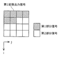
分割部210によって分割された第1部分信号y1L
mは、図5Aに示すように、一次元に並び替えられ、第2変換部220に入力される。
The first partial signal y 1L m divided by the dividing unit 210 is rearranged in one dimension and input to the second converting unit 220 as shown in FIG. 5A.
次に、第2変換部220は、第2変換行列を用いて第1部分信号y1L
mに第2変換を行うことで、第2変換出力信号y2
mを生成する(ステップS116)。具体的には、第2変換部220は、第1部分信号y1L
mの相関を軽減し、より低周波数帯域にエネルギーを集中させるように、第1部分信号y1L
mを第2変換出力信号y2
mに変換する。
Next, the second conversion unit 220 performs the second conversion on the first partial signal y 1L m using the second conversion matrix to generate the second conversion output signal y 2 m (step S116). Specifically, the second conversion unit 220 reduces the correlation of the first partial signal y 1L m and concentrates the first partial signal y 1L m on the second converted output signal so as to concentrate energy in a lower frequency band. Convert to y 2 m .
このとき、第2変換係数として、例えば、以前に入力された第1部分信号y1L
mの第2変換の際に既に算出された係数を用いることができる。つまり、第2変換を行う度に第2変換係数を算出しなくてもよいので、第2変換係数の算出にかかる演算量を低減することができる。第2変換係数を算出する場合の具体的な処理については、後で説明する。
At this time, for example, a coefficient already calculated at the time of the second conversion of the first partial signal y 1L m inputted previously can be used as the second conversion coefficient. That is, since it is not necessary to calculate the second conversion coefficient every time the second conversion is performed, it is possible to reduce the amount of calculation required for calculating the second conversion coefficient. Specific processing for calculating the second conversion coefficient will be described later.
次に、統合部230は、第2変換出力信号y2
mと第2部分信号y1H
n-mとを統合することで、変換出力信号ynを生成する(ステップS118)。具体的には、統合部230は、第2変換出力信号y2
mを一次元に並び替えられる前の次元に並び替え、分割統合情報に基づいて、並び替えた後の第2変換出力信号y2
mと第2部分信号y1H
n-mとを統合する。
Next, the integrating unit 230 generates the converted output signal y n by integrating the second converted output signal y 2 m and the second partial signal y 1H nm (step S118). Specifically, the integration unit 230 rearranges the second converted output signal y 2 m to a dimension before being rearranged in one dimension, and the second converted output signal y after the rearrangement based on the division integration information. 2 m and the second partial signal y 1H nm are integrated.
次に、量子化部120は、以上のようにして生成された変換出力信号ynを量子化することで、量子化係数を生成する(ステップS120)。最後に、エントロピー符号化部130は、量子化係数をエントロピー符号化することで、符号化信号を生成する(ステップS130)。
Then, the quantization unit 120, the converted output signal y n generated as described above by quantization to generate quantized coefficients (step S120). Finally, the entropy encoding unit 130 generates an encoded signal by entropy encoding the quantization coefficient (step S130).
なお、図5Bに示すように、分割部210は、第1部分信号y1L
mを一次元に並び替えることなく、そのまま第2変換部220に出力してもよい。この場合、第2変換部220は、二次元の第1部分信号y1L
mに第2変換を行うことで、二次元の第2変換出力信号y2
mを生成する。ここでは、第2変換部220は、例えば、非分離型の第2変換を行う。そして、統合部230では、第2変換出力信号y2
mの並び替えを行うことなく、第2変換出力信号y2
mと第2部分信号y1H
n-mとを統合する。
As shown in FIG. 5B, the dividing unit 210 may output the first partial signal y 1L m to the second converting unit 220 as it is without rearranging it in a one-dimensional manner. In this case, the second conversion unit 220, by performing a second transformation to the first partial signal y 1L m two-dimensional, to generate a second conversion output signal y 2 m in two dimensions. Here, the second converter 220 performs, for example, non-separable second conversion. Then, the integrating unit 230, without performing the reordering of the second conversion output signal y 2 m, to integrate the second conversion output signal y 2 m and a second partial signal y 1H n-m.
また、図5A及び図5Bでは、第2変換の対象は、第1変換出力信号の任意の領域(非矩形領域)であるように図示したが、これに限るものではなく矩形領域であっても構わない。具体的には、図5A及び図5Bに示す例では、第2変換部220は、第1変換出力信号の低周波成分の係数値を含む、行列表現した場合における非矩形領域に含まれる信号を、第1部分信号として第2変換を行う。これに対して、第2変換部220は、第1変換出力信号の低周波成分の係数値を含む、行列表現した場合における矩形領域に含まれる係数値を含む信号を、第1部分信号として第2変換を行ってもよい。
In FIGS. 5A and 5B, the target of the second conversion is illustrated as an arbitrary region (non-rectangular region) of the first conversion output signal. However, the present invention is not limited to this and may be a rectangular region. I do not care. Specifically, in the example illustrated in FIGS. 5A and 5B, the second conversion unit 220 includes a signal included in a non-rectangular region in the case of a matrix representation including the coefficient value of the low frequency component of the first conversion output signal. The second conversion is performed as the first partial signal. On the other hand, the second conversion unit 220 uses, as a first partial signal, a signal including a coefficient value included in a rectangular area in the case of matrix expression including a coefficient value of a low frequency component of the first conversion output signal. Two conversions may be performed.
次に、第1変換係数、第2変換係数及び分割統合情報を決定する場合の動作及び構成について説明する。
Next, the operation and configuration when determining the first transform coefficient, the second transform coefficient, and the division integration information will be described.
図6は、本発明の実施の形態1に係る変換部110における変換処理の一例を示すフローチャートである。また、図7は、本発明の実施の形態1に係る変換部110における変換係数の導出の一例を示す概念図である。
FIG. 6 is a flowchart showing an example of conversion processing in the conversion unit 110 according to Embodiment 1 of the present invention. FIG. 7 is a conceptual diagram showing an example of the derivation of the transform coefficient in the transform unit 110 according to Embodiment 1 of the present invention.
図7に示すように、変換部110は、さらに、第1変換係数導出部202と、第2変換係数導出部222とを備える。なお、図7には、分割部210及び統合部230は、図示していない。
As shown in FIG. 7, the conversion unit 110 further includes a first conversion coefficient derivation unit 202 and a second conversion coefficient derivation unit 222. In FIG. 7, the dividing unit 210 and the integrating unit 230 are not shown.
まず、図6に示すように、第1変換係数導出部202は、変換入力信号xnに基づいて第1変換係数を決定する(ステップS111)。次に、第1変換部200は、第1変換係数導出部202によって決定された第1変換係数で構成される第1変換行列を用いて、変換入力信号xnに第1変換を行う(ステップS112)。
First, as shown in FIG. 6, the first transform coefficient deriving unit 202 determines the first transform coefficient based on the transform input signal xn (step S111). Next, the first conversion unit 200 performs the first conversion on the conversion input signal xn using the first conversion matrix configured by the first conversion coefficients determined by the first conversion coefficient derivation unit 202 (step) S112).
次に、分割統合情報が決定される(ステップS113)。分割統合情報は、予め決められた分割を行うように分割部210を制御するものであれば、符号化装置100のメモリ等から読み出す。また、分割統合情報が、第1変換出力信号y1
nに応じた分割を行うよう分割部210を制御するものであれば、第1変換出力信号y1
nに基づいてエネルギー状態の分布に鑑みて分割統合情報を導出する。
Next, division integration information is determined (step S113). The division integration information is read from the memory or the like of the encoding device 100 as long as it controls the division unit 210 to perform predetermined division. Also, the segmentation-concatenation information, as long as it controls the division unit 210 to perform the division corresponding to the first conversion output signal y 1 n, in view of the distribution of energy states based on the first conversion output signal y 1 n To derive the division integration information.
このようにして決定された分割統合情報に基づいて、分割部210は、第1変換出力信号y1
nを分割する(ステップS114)。
Based on the division integration information determined in this way, the dividing unit 210 divides the first converted output signal y 1 n (step S114).
次に、第2変換係数導出部222は、第1部分信号y1L
mに基づいて第2変換係数を決定する(ステップS115)。次に、第2変換部220は、決定された第2変換係数で構成される第2変換行列を用いて、第1部分信号y1
nに第2変換を行う(ステップS116)。
Next, the second transform coefficient deriving unit 222 determines a second transform coefficient based on the first partial signal y 1L m (step S115). Next, the second conversion unit 220 performs the second conversion on the first partial signal y 1 n using the second conversion matrix configured with the determined second conversion coefficient (step S116).
最後に、統合部230は、第2変換出力信号y2
mと分割された第2部分信号y1H
n-mとを統合し、変換出力信号ynとして出力する(ステップS118)。
Finally, integrating unit 230, and a second partial signal y IH n-m divided second conversion output signal y 2 m integrates and outputs a conversion output signal y n (step S118).
図7を用いて、第1変換部200における第1変換と第2変換部220における第2変換とについて詳細に説明する。
The first conversion in the first conversion unit 200 and the second conversion in the second conversion unit 220 will be described in detail with reference to FIG.
多くのサンプルを含むある集合SAには、第1変換部200に入力される変換入力信号xnが含まれている。第1変換係数導出部202は、例えば、KLTを用いて、この集合SAに含まれる多くのサンプルに平均的に最適化された第1変換係数を求める。
A certain set S A including many samples includes a converted input signal x n input to the first converter 200. First conversion coefficient deriving unit 202, for example, using a KLT, determining a first transform coefficients averaged optimized for many samples included in this set S A.
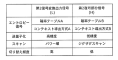
このように多くのサンプルを含む集合SAに基づいて、第1変換係数を求めることにより、個々の変換入力信号xnの統計的性質にあまり影響を受けず、多少異なる性質であっても同じ第1変換係数で構成される第1変換行列を用いて第1変換を行うことができる。よって、第1変換係数の更新頻度を抑えることができ、つまり、図4に示す処理のように、第1変換係数の決定を行わない場合を多くすることができるので、演算量を削減することができる。
By obtaining the first transform coefficient based on the set S A including a large number of samples in this way, the statistical properties of the individual transform input signals xn are not significantly affected, and even if the properties are somewhat different, The first transformation can be performed using a first transformation matrix composed of first transformation coefficients. Therefore, the update frequency of the first transform coefficient can be suppressed, that is, the number of cases where the determination of the first transform coefficient is not performed as in the process shown in FIG. Can do.
また、第1変換係数の更新をする場合であっても、更新前と後の変換係数の個々の値の変化量は小さいため、差分情報量を少なくすることができる。したがって、第1変換係数を復号装置に送信する場合に、符号量の増加を抑制することができる。
In addition, even when the first conversion coefficient is updated, the amount of difference information can be reduced because the amount of change in individual values of the conversion coefficient before and after the update is small. Therefore, when the first transform coefficient is transmitted to the decoding device, an increase in the code amount can be suppressed.
一方、第2変換部220には、第1変換出力信号y1
nを構成する係数値のうち、相関エネルギーの大きな部分である第1部分信号y1L
mが入力される。第2変換係数導出部222は、第1変換係数導出部202と同様に、例えばKLTを用いて、第1部分信号y1L
mを含み、集合SAと比較してサンプル数の少ない集合SCに含まれるサンプルに平均的に最適化された第2変換係数を求める。
On the other hand, the second conversion unit 220 receives the first partial signal y 1L m which is a portion having a large correlation energy among the coefficient values constituting the first conversion output signal y 1 n . Second conversion coefficient deriving unit 222, like the first conversion coefficient deriving unit 202, for example, using a KLT, comprises a first partial signal y 1L m, less number of samples as compared to the set S A set S C The second transform coefficient that is averagely optimized for the samples included in is obtained.
このように、集合SCを集合SAより小さい集合とすることで、入力される第1変換出力信号y1
nの統計的性質の変化に鋭敏に追従でき、さらなる相関の軽減とエネルギー圧縮とが可能となる。なお、小さい集合SCとすることで変換係数の更新頻度は高まるが、第1部分信号y1L
mは、第1変換出力信号y1
nの一部であり、変換入力信号xnよりも次元数が少ないため、第2変換行列の要素数は少なくなり、高効率な変換と、演算量及びデータ量の削減とを両立させることができる。
In this manner, by the set S A smaller set the set S C, sharply can follow changes in the statistical properties of the first conversion output signal y 1 n inputted, and further the correlation reduction and energy compaction Is possible. Although the update frequency of the transform coefficients by a small set S C is increased, the first partial signal y 1L m, a part of the first conversion output signal y 1 n, dimension than converting the input signal x n Since the number is small, the number of elements of the second transformation matrix is small, and it is possible to achieve both high-efficiency conversion and reduction of the calculation amount and data amount.
なお、第2変換部220には、第1変換出力信号y1
nを構成する係数値のうち相関エネルギーの大きな部分である第1部分信号y1L
mが入力されるとしたが、これは、第1変換出力信号y1
nの自己相関の高い位置を選択しているといえる。これに対して、類似の方法として、第1変換出力信号y1
nの相互相関の高い位置を第1部分信号y1L
mとして選択してもよい。
The second conversion unit 220 receives the first partial signal y 1L m , which is a portion having a large correlation energy, among the coefficient values constituting the first conversion output signal y 1 n . It can be said that a position having a high autocorrelation of the first converted output signal y 1 n is selected. On the other hand, as a similar method, a position having a high cross-correlation of the first converted output signal y 1 n may be selected as the first partial signal y 1L m .
なお、第1部分信号y1L
mと第2変換出力信号y2
mとのそれぞれについて、次元の並び替えを分割部210と統合部230とが行うこととしたが、それぞれの並び替えを第2変換部220が行う構成であってもよい。また、符号化の対象が音声データ等の一次元信号である場合、あるいは、一次元信号処理と見なすことができる分離型の各次元の処理において、変換部110に入力される変換入力信号xnは一次元であるため、これらの並び替えの処理は不要となる。
Note that the division unit 210 and the integration unit 230 perform the dimensional rearrangement for each of the first partial signal y 1L m and the second converted output signal y 2 m . The structure which the conversion part 220 performs may be sufficient. Also, when the target of encoding is a one-dimensional signal such as speech data, or in each type of separation-type processing that can be regarded as one-dimensional signal processing, a conversion input signal x n input to the conversion unit 110. Since these are one-dimensional, these sort processes are unnecessary.
以上のように、本発明の実施の形態1に係る符号化装置100は、入力信号に第1変換を行い、第1変換後の信号の一部である第1部分信号に第2変換を行うことを特徴とする。これにより、本発明の実施の形態1に係る符号化装置100によれば、入力信号の統計的性質に基づいて計算される変換係数を用いる変換において、変換の演算量の削減、及び、変換行列の要素数(データ量)の削減を実現することができる。
As described above, encoding apparatus 100 according to Embodiment 1 of the present invention performs first conversion on an input signal and performs second conversion on a first partial signal that is a part of the signal after the first conversion. It is characterized by that. Thereby, according to the encoding apparatus 100 which concerns on Embodiment 1 of this invention, in the conversion using the conversion factor calculated based on the statistical property of an input signal, reduction of the computational complexity of conversion, and a conversion matrix The number of elements (data amount) can be reduced.
なお、上記の実施の形態1に係る符号化装置100では、第1変換出力信号y1
nを第1部分信号y1L
mと第2部分信号y1H
n-mとに分割し、第2変換後に統合するが、明示的に分割しなくてもよく、実質的に分割すればよい。すなわち、第1変換出力信号y1
nのうち、第2変換を実行する対象となる部分を決定すればよい。例えば、第2変換の際に、第2変換の対象とならない要素に対する行の対角要素を1、非対角要素を0にすることで、実質的に第1部分信号y1L
mにのみ、第2変換を行うことができる。図8に行列演算の具体例を示す。
In the encoding apparatus 100 according to the first embodiment described above, by dividing the first conversion output signal y 1 n into a first partial signal y 1L m and the second partial signal y IH n-m, the second conversion Although they will be integrated later, it is not necessary to explicitly divide them. In other words, a portion to be subjected to the second conversion may be determined in the first conversion output signal y 1 n . For example, in the second conversion, by setting the diagonal element of the row for the element that is not subject to the second conversion to 1 and the non-diagonal element to 0, substantially only in the first partial signal y 1L m , A second conversion can be performed. FIG. 8 shows a specific example of matrix operation.
図8(a)のように、4点のベクトルXnのうちの3点(X1,X2,X3)に対して3×3の大きさの行列A3を乗算して得られる結果と、図8(b)のように、A3を4×4へ拡張し、拡張の際、対角要素は1、非対角要素は0を設定した拡張後の行列A4と4点のXとの乗算結果の3点の部分とは、一致する。
As shown in FIG. 8A, the result obtained by multiplying 3 points (X 1 , X 2 , X 3 ) of 4 vectors X n by a 3 × 3 matrix A 3 When, as shown in FIG. 8 (b), the extension of the a 3 to 4 × 4, upon expansion, diagonal elements 1, the off-diagonal elements of the matrix a 4 and 4 points after expansion is set to 0 The three-point portion of the multiplication result with X matches.
図9は、本発明の実施の形態1の変形例に係る符号化装置100aの構成の一例を示すブロック図である。
FIG. 9 is a block diagram showing an example of the configuration of the encoding device 100a according to the modification of the first embodiment of the present invention.
符号化装置100aは、変換部110aと、量子化部120と、エントロピー符号化部130とを備える。なお、図3に示す符号化装置100と同じ動作を行う処理部には、同じ符号を付しており、以下では説明を省略する。
The encoding device 100a includes a conversion unit 110a, a quantization unit 120, and an entropy encoding unit 130. In addition, the same code | symbol is attached | subjected to the process part which performs the same operation | movement as the encoding apparatus 100 shown in FIG. 3, and description is abbreviate | omitted below.
変換部110aは、第1変換部200と、第2変換部220aとを備える。つまり、変換部110aは、図3に示す変換部110と比較して、分割部210と、統合部230とを備えていない点と、さらに、第2変換部220の代わりに第2変換部220aとを備える点とが異なっている。
The conversion unit 110a includes a first conversion unit 200 and a second conversion unit 220a. That is, the conversion unit 110a does not include the division unit 210 and the integration unit 230 as compared with the conversion unit 110 illustrated in FIG. 3, and the second conversion unit 220a instead of the second conversion unit 220. It is different from the point provided with.
第2変換部220aは、第1変換出力信号y1
nの一部である第1部分信号y1L
mを含む集合の統計特性に基づいて決定された第2変換係数で構成される第2変換行列を用いて、第1部分信号y1L
mに第2変換を行うことで、第2変換出力信号y2
mを生成する。具体的には、第2変換部220aは、第1変換出力信号y1
nを構成する係数値のうち、第2変換の対象となる係数値を決定し、決定した係数値から構成される信号を第1部分信号y1L
mとして、第2変換を行う。より具体的には、第2変換部220aは、第1変換出力信号y1
nを構成する複数の係数値のうち、所定の閾値より値の大きな係数値を含む信号を、第1部分信号y1L
mとして、第2変換を行う。
The second conversion unit 220a is a second conversion composed of a second conversion coefficient determined based on the statistical characteristics of the set including the first partial signal y 1L m that is a part of the first conversion output signal y 1 n. The second conversion output signal y 2 m is generated by performing the second conversion on the first partial signal y 1L m using the matrix. Specifically, the second conversion unit 220a determines a coefficient value to be subjected to the second conversion among coefficient values constituting the first conversion output signal y 1 n, and a signal configured from the determined coefficient value. Is the first partial signal y 1L m , and the second conversion is performed. More specifically, the second conversion unit 220a outputs a signal including a coefficient value larger than a predetermined threshold value among the plurality of coefficient values constituting the first converted output signal y 1 n to the first partial signal y. The second conversion is performed with 1L m .
そして、第2変換部220aは、生成した第2変換出力信号y2
mと、第1変換出力信号y1
nのうち第1部分信号y1L
m以外の部分である第2部分信号y1H
n-mとを含む変換出力信号ynを出力する。
The second conversion unit 220a includes a second conversion output signal y 2 m generated, the second partial signal y IH n is a portion other than the first partial signal y 1L m of the first conversion output signal y 1 n and it outputs the converted output signal y n comprising a -m.
図10は、図9に示す符号化装置100aの動作の一例を示すフローチャートである。
FIG. 10 is a flowchart showing an example of the operation of the encoding device 100a shown in FIG.
まず、変換部110aが、入力された変換入力信号xnを変換することで、変換出力信号ynを生成する(ステップS110a)。具体的には、まず、入力された変換入力信号xnに対して、第1変換部200は、第1変換を行うことで、第1変換出力信号y1
nを生成する(ステップS112)。
First, the conversion unit 110a is to convert the converted input signal x n input, generates a converted output signal y n (step S110a). Specifically, first, with respect to the inputted converted input signal x n, the first conversion unit 200, by performing a first conversion, to generate a first conversion output signal y 1 n (step S112).
次に、第2変換部220aが、第1部分信号y1L
mに第2変換を行う(ステップS116a)。例えば、第2変換部220aは、第1変換出力信号y1
nのうち、第2変換を行う対象となる部分を、第1部分信号y1L
mとして決定し、決定した第1部分信号y1L
mに対して第2変換行列を用いて第2変換を行う。
Next, the second conversion unit 220a performs the second conversion on the first partial signal y 1L m (step S116a). For example, the second conversion unit 220a determines, as the first partial signal y 1L m , a portion to be subjected to the second conversion in the first converted output signal y 1 n , and the determined first partial signal y 1L A second transformation is performed on m using a second transformation matrix.
次に、量子化部120は、第2変換出力信号y2
mを含む変換出力信号ynを量子化することで、量子化係数Cnを生成する(ステップS120)。最後に、エントロピー符号化部130は、量子化係数Cnをエントロピー符号化することで、符号化信号を生成する(ステップS130)。
Next, the quantization unit 120 generates a quantization coefficient C n by quantizing the converted output signal y n including the second converted output signal y 2 m (step S120). Finally, the entropy encoding unit 130 generates an encoded signal by entropy encoding the quantization coefficient C n (step S130).
以上のように、実施の形態1の変形例に係る符号化装置100aも、部分的に2段階の変換を行うことで、符号化処理における演算量の増加、及び、変換係数のデータ量の増加を抑制することができる。
As described above, the encoding apparatus 100a according to the modification of the first embodiment also performs an increase in the amount of calculation in the encoding process and the increase in the data amount of the transform coefficient by performing two-stage conversion partially. Can be suppressed.
(実施の形態2)
本発明の実施の形態2に係る復号装置は、符号化信号をエントロピー復号することで、復号量子化係数を生成するエントロピー復号部と、復号量子化係数を逆量子化することで、復号変換出力信号を生成する逆量子化部と、復号変換出力信号を逆変換することで、復号信号を生成する逆変換部とを備える。そして、逆変換部は、第2逆変換係数で構成される第2逆変換行列を用いて、復号変換出力信号の一部である第2復号変換出力信号に第2逆変換を行うことで、第1復号部分信号を生成する第2逆変換部と、第1復号部分信号と、復号変換出力信号のうち第2復号変換出力信号以外の部分である第2復号部分信号とを含む第1復号変換出力信号に、第1逆変換係数で構成される第1逆変換行列を用いて第1逆変換を行うことで、復号信号を生成する第1逆変換部とを備える。
(Embodiment 2)
The decoding apparatus according to Embodiment 2 of the present invention includes an entropy decoding unit that generates a decoded quantized coefficient by entropy decoding the encoded signal, and a decoding conversion output by dequantizing the decoded quantized coefficient. An inverse quantization unit that generates a signal and an inverse transform unit that generates a decoded signal by performing inverse transform on the decoded transform output signal. Then, the inverse transform unit performs the second inverse transform on the second decoded transform output signal that is a part of the decoded transform output signal, using the second inverse transform matrix configured by the second inverse transform coefficient, 1st decoding including the 2nd inverse transformation part which generates the 1st decoding partial signal, the 1st decoding partial signal, and the 2nd decoding partial signal which is parts other than the 2nd decoding conversion output signal among decoding conversion output signals A first inverse transform unit that generates a decoded signal by performing a first inverse transform on the transformed output signal using a first inverse transform matrix configured with a first inverse transform coefficient;
言い換えると、本発明の実施の形態2に係る復号装置は、符号化信号に対して2段階の逆変換を行うことを特徴とする。具体的には、本発明の実施の形態2に係る復号装置は、符号化信号にエントロピー復号及び逆量子化を行うことで生成される復号変換出力信号の一部である第2復号変換出力信号に第2逆変換を行い、第2逆変換後の信号と、復号変換出力信号の残りの部分である第2復号部分信号とを含む第1復号変換出力信号に第1逆変換を行うことを特徴とする。
In other words, the decoding apparatus according to Embodiment 2 of the present invention is characterized by performing a two-step inverse transform on the encoded signal. Specifically, the decoding apparatus according to Embodiment 2 of the present invention provides a second decoded converted output signal that is a part of a decoded converted output signal generated by performing entropy decoding and inverse quantization on the encoded signal. And performing the first inverse transform on the first decoded transform output signal including the signal after the second inverse transform and the second decoded partial signal which is the remaining portion of the decoded transformed output signal. Features.
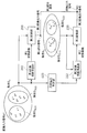
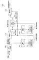
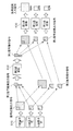
図11Aは、本発明の実施の形態2に係る復号装置300の構成の一例を示すブロック図である。復号装置300には、音声データや動画像データを低ビットレートで符号化した符号化信号が入力され、復号装置300は、符号化信号から音声データや動画像データを復号することで、復号信号を生成する。
FIG. 11A is a block diagram showing an exemplary configuration of decoding apparatus 300 according to Embodiment 2 of the present invention. The decoding device 300 receives an encoded signal obtained by encoding audio data or moving image data at a low bit rate, and the decoding device 300 decodes the audio data or moving image data from the encoded signal to thereby generate a decoded signal. Is generated.
復号装置300は、符号化信号に対してエントロピー復号をし、逆量子化をし、逆変換をするという符号化の処理とほぼ逆の処理を行う。図11Aに示すように、復号装置300は、エントロピー復号部310と、逆量子化部320と、逆変換部330とを備える。
The decoding apparatus 300 performs entropy decoding on the encoded signal, performs inverse quantization, and performs almost the inverse process to the encoding process of performing inverse transform. As illustrated in FIG. 11A, the decoding device 300 includes an entropy decoding unit 310, an inverse quantization unit 320, and an inverse transform unit 330.
エントロピー復号部310は、入力された符号化信号をエントロピー復号することで、復号量子化係数を生成する。復号量子化係数は、実施の形態1に係る量子化部120が生成する量子化係数に相当する。
The entropy decoding unit 310 generates a decoded quantized coefficient by entropy decoding the input encoded signal. The decoded quantization coefficient corresponds to the quantization coefficient generated by the quantization unit 120 according to Embodiment 1.
逆量子化部320は、エントロピー復号部310によって生成された復号量子化係数を逆量子化することで、復号変換出力信号を生成する。復号変換出力信号は、実施の形態1に係る変換部110が生成する変換出力信号に相当する。
The inverse quantization unit 320 generates a decoded transform output signal by inversely quantizing the decoded quantized coefficient generated by the entropy decoding unit 310. The decoded conversion output signal corresponds to the conversion output signal generated by conversion section 110 according to Embodiment 1.
逆変換部330は、逆量子化部320によって生成された復号変換出力信号を逆変換することで、復号信号を生成する。復号信号は、実施の形態1に係る変換部110に入力される変換入力信号に相当する。
The inverse conversion unit 330 generates a decoded signal by performing inverse conversion on the decoded conversion output signal generated by the inverse quantization unit 320. The decoded signal corresponds to a converted input signal input to converting section 110 according to Embodiment 1.
以下では、本発明の実施の形態2に係る逆変換部330について、詳細に説明する。図11Bは、本発明の実施の形態2に係る復号装置300における逆変換部330の構成の一例を示すブロック図である。図11Bに示すように、逆変換部330は、分割部400と、第2逆変換部410と、統合部420と、第1逆変換部430とを備える。
Hereinafter, the inverse transform unit 330 according to Embodiment 2 of the present invention will be described in detail. FIG. 11B is a block diagram showing an exemplary configuration of inverse transform section 330 in decoding apparatus 300 according to Embodiment 2 of the present invention. As illustrated in FIG. 11B, the inverse transform unit 330 includes a dividing unit 400, a second inverse transform unit 410, an integration unit 420, and a first inverse transform unit 430.
分割部400は、復号変換出力信号を2つの部分に分割する。具体的には、分割部400は、逆量子化部320によって生成された復号変換出力信号を、分割統合情報を用いて第2復号変換出力信号と第2復号部分信号とに分割する。
The dividing unit 400 divides the decoded conversion output signal into two parts. Specifically, the dividing unit 400 divides the decoded transformed output signal generated by the inverse quantization unit 320 into a second decoded transformed output signal and a second decoded partial signal using the division integration information.
第2復号変換出力信号は、実施の形態1に係る第2変換部220によって生成された第2変換出力信号に相当する。すなわち、第2復号変換出力信号は、符号化の際に、第2変換が実行された部分に相当し、第2逆変換の対象となる部分である。また、第2復号部分信号は、実施の形態1に係る分割部210によって分割された第2部分信号に相当する。
The second decoded conversion output signal corresponds to the second conversion output signal generated by the second conversion unit 220 according to Embodiment 1. That is, the second decoded conversion output signal corresponds to a portion where the second conversion has been performed at the time of encoding, and is a portion to be subjected to the second inverse conversion. Further, the second decoded partial signal corresponds to the second partial signal divided by dividing section 210 according to Embodiment 1.
第2逆変換部410は、第2復号変換出力信号に第2逆変換を行うことで、第1復号部分信号を生成する。第1復号部分信号は、実施の形態1に係る分割部210によって分割された第1部分信号に相当する。
The second inverse transform unit 410 generates a first decoded partial signal by performing a second inverse transform on the second decoded transform output signal. The first decoded partial signal corresponds to the first partial signal divided by dividing section 210 according to Embodiment 1.
統合部420は、第2逆変換部410によって生成された第1復号部分信号と、第2復号部分信号とを統合することで、第1復号変換出力信号を生成する。第1復号変換出力信号は、実施の形態1に係る第1変換部200によって生成された第1変換出力信号に相当する。
The integrating unit 420 integrates the first decoded partial signal generated by the second inverse converting unit 410 and the second decoded partial signal to generate a first decoded converted output signal. The first decoded conversion output signal corresponds to the first conversion output signal generated by the first conversion unit 200 according to Embodiment 1.
第1逆変換部430は、第1逆変換行列を用いて第1復号変換出力信号に第1逆変換を行うことで、復号信号を生成する。第1復号変換出力信号は、第2復号変換出力信号と第2復号部分信号とを含む信号である。
The first inverse transform unit 430 generates a decoded signal by performing a first inverse transform on the first decoded transform output signal using the first inverse transform matrix. The first decoded converted output signal is a signal including the second decoded converted output signal and the second decoded partial signal.
なお、復号装置300には音声データ、静止画像データ、動画像データなどの各種データである信号を符号化することで生成された符号化信号が入力される。逆変換部330には、この符号化信号をエントロピー復号し、かつ、逆量子化することで生成された信号が、復号変換出力信号y^nとして入力される。ここで、記号「^(ハット)」は、それぞれ直前の文字の上に付される記号を示し、本明細書では、以下、記号「^(ハット)」を同様な意味で使用する。
Note that the decoding apparatus 300 receives an encoded signal generated by encoding a signal that is various data such as audio data, still image data, and moving image data. A signal generated by entropy decoding and dequantizing this encoded signal is input to the inverse transform unit 330 as a decoded transform output signal y n . Here, the symbol “^ (hat)” indicates a symbol added on the immediately preceding character, and the symbol “^ (hat)” is used in the same sense hereinafter.
続いて、本発明の実施の形態2に係る復号装置300の動作の一例について説明する。
Subsequently, an example of the operation of the decoding apparatus 300 according to Embodiment 2 of the present invention will be described.
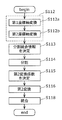
図12は、本発明の実施の形態2に係る復号装置300の動作の一例を示すフローチャートである。また、図13A及び図13Bは、本発明の実施の形態2に係る復号装置300における逆変換部330のデータフローの一例を概念的に示す図である。
FIG. 12 is a flowchart showing an example of the operation of the decoding apparatus 300 according to Embodiment 2 of the present invention. 13A and 13B are diagrams conceptually showing an example of the data flow of inverse transform section 330 in decoding apparatus 300 according to Embodiment 2 of the present invention.
まず、エントロピー復号部310は、符号化信号をエントロピー復号することで、復号量子化係数を生成する(ステップS210)。次に、逆量子化部320は、復号量子化係数を逆量子化することで、復号変換出力信号y^nを生成する(ステップS220)。
First, the entropy decoding unit 310 generates a decoded quantized coefficient by entropy decoding the encoded signal (step S210). Next, the inverse quantization unit 320 generates a decoded transform output signal y ^ n by inversely quantizing the decoded quantized coefficient (step S220).
次に、逆変換部330は、復号変換出力信号y^nを逆変換することで、復号信号x^nを生成する(ステップS230)。
Next, the inverse conversion unit 330 generates a decoded signal x ^ n by performing inverse conversion on the decoded conversion output signal y ^ n (step S230).
具体的には、まず、分割部400が、分割統合情報に基づいて、復号変換出力信号y^nを、2つの領域に分割する(ステップS232)。つまり、分割部400は、復号変換出力信号y^nを第2復号変換出力信号y^2
mと第2復号部分信号y^1H
n-mとに分割する。第2復号変換出力信号y^2
mは、復号変換出力信号y^nを構成する複数の係数値のうち、第2逆変換の対象となる部分である。第2復号部分信号y^1H
n-mは、第2復号変換出力信号y^2
mは、復号変換出力信号y^nを構成する複数の係数値のうち、第2逆変換の対象とならない部分である。
Specifically, first, the dividing unit 400 divides the decoded conversion output signal ^ n into two regions based on the division integration information (step S232). That is, the dividing unit 400 divides the decoded converted output signal ^ n into a second decoded converted output signal ^ 2 m and a second decoded partial signal ^ 1H nm . The second decoded conversion output signal ^ 2 m is a portion to be subjected to the second inverse conversion among a plurality of coefficient values constituting the decoded conversion output signal ^ n . The second decoded partial signal y ^ 1H n-m, the second decoded transformed signals y ^ 2 m, of the plurality of coefficient values that constitute the decoded converted output signal y ^ n, not subject to the second inverse transformation Part.
このとき、分割統合情報として、例えば、以前に入力された復号変換出力信号y^nの分割の際に用いた分割統合情報を用いることができる。つまり、分割を行う度に、新たな分割統合情報を決定する必要はない。
At this time, as the division integration information, for example, the division integration information used at the time of dividing the decoding conversion output signal y ^ n input previously can be used. That is, it is not necessary to determine new division integration information every time division is performed.
分割部400によって分割された第2復号変換出力信号y^2
mは、図13Aに示すように、一次元に並び替えられ、第2逆変換部410に入力される。
The second decoded transformation output signal y 2 m divided by the dividing unit 400 is rearranged in one dimension and input to the second inverse transformation unit 410 as shown in FIG. 13A.
次に、第2逆変換部410は、第2逆変換行列を用いて第2復号変換出力信号y^2
mに第2逆変換を行うことで、第1復号部分信号y^1L
mを生成する(ステップS234)。
Next, the second inverse transform unit 410 generates the first decoded partial signal 第1L m by performing the second inverse transform on the second decoded transform output signal ^ 2 m using the second inverse transform matrix. (Step S234).
このとき、第2逆変換係数として、例えば、以前に入力された第2復号変換出力信号y^2
mの第2逆変換の際に既に決定された係数を用いることができる。つまり、第2逆変換を行う度に、新たな第2逆変換係数を決定する必要はない。
At this time, as the second inverse transform coefficient, for example, a coefficient already determined at the time of the second inverse transform of the previously input second decoded transform output signal y ^ 2 m can be used. That is, it is not necessary to determine a new second inverse transform coefficient each time the second inverse transform is performed.
次に、統合部420は、第2復号部分信号y^1H
n-mと、第1復号部分信号y^1L
mとを統合することで、第1復号変換出力信号y^1
nを生成する(ステップS236)。具体的には、統合部420は、第1復号部分信号y^1L
mを一次元に並び替えられる前の次元に並び替え、分割統合情報に基づいて、並び替えた後の第1復号部分信号y^1L
mと第2復号部分信号y^1H
n-mとを統合する。
Next, the integration unit 420 integrates the second decoded partial signal ^ 1H nm and the first decoded partial signal ^ 1L m to generate the first decoded converted output signal ^ 1 n . (Step S236). Specifically, the integration unit 420 rearranges the first decoded partial signal y 1 L m to the dimension before being rearranged in one dimension, and the first decoded partial signal after rearrangement based on the division integration information. ^ 1L m and the second decoded partial signal ^ 1H nm are integrated.
次に、第1逆変換部430は、第1逆変換行列を用いて、第1復号変換出力信号y^1
nに第1逆変換を行うことで、復号信号x^nを生成する(ステップS238)。
Next, the first inverse transform unit 430 performs the first inverse transform on the first decoded transform output signal ^ 1 n using the first inverse transform matrix, thereby generating the decoded signal x n (step S1). S238).
このとき、第1逆変換係数として、例えば、以前に入力された第1復号変換出力信号y^1
nの第1逆変換の際に既に決定された係数を用いることができる。つまり、第1逆変換を行う度に、新たな第1逆変換係数を決定する必要はない。
At this time, as the first inverse transform coefficient, for example, a coefficient already determined at the time of the first inverse transform of the previously input first decoded transform output signal y 1 n can be used. That is, it is not necessary to determine a new first inverse transform coefficient each time the first inverse transform is performed.
なお、図13Bに示すように、分割部400は、第2復号変換出力信号y^2
mを一次元に並び替えることなく、そのまま第2逆変換部410に出力してもよい。この場合、第2逆変換部410は、二次元の第2復号変換出力信号y^2
mに第2逆変換を行うことで、二次元の第1復号部分信号y^1L
mを生成する。そして、統合部420では、第1復号部分信号y^1L
mの並び替えを行うことなく、第1復号部分信号y^1L
mと第2復号部分信号y^1H
n-mとを統合する。
As illustrated in FIG. 13B, the dividing unit 400 may output the second decoded transformation output signal y ^ 2 m to the second inverse transformation unit 410 as it is without rearranging it in one dimension. In this case, the second inverse transform unit 410 performs the second inverse transform on the two-dimensional second decoded transform output signal y 2 m , thereby generating the two-dimensional first decoded partial signal y 1L m . Then, the integrating unit 420, without performing the reordering of the first decoded partial signal y ^ 1L m, it integrates a first decoded partial signal y ^ 1L m and a second decoded partial signal y ^ 1H n-m.
また、図13A及び図13Bでは、第2逆変換の対象は、復号変換出力信号の任意の領域(非矩形領域)であるように図示したが、これに限るものではなく矩形領域であっても構わない。具体的には、図13A及び図13Bに示す例では、第2逆変換部410は、復号変換出力信号の低周波成分の係数値を含む、行列表現した場合における非矩形領域に含まれる信号を、第2復号変換出力信号として第2逆変換を行う。これに対して、第2逆変換部410は、復号変換出力信号の低周波成分の係数値を含む、行列表現した場合における矩形領域に含まれる係数値を含む信号を、第2復号変換出力信号として第2逆変換を行ってもよい。
In FIGS. 13A and 13B, the target of the second inverse transform is illustrated as an arbitrary region (non-rectangular region) of the decoded transform output signal. However, the present invention is not limited to this and may be a rectangular region. I do not care. Specifically, in the example illustrated in FIGS. 13A and 13B, the second inverse transform unit 410 includes a signal included in the non-rectangular region in the case of matrix representation including the coefficient value of the low frequency component of the decoded transform output signal. Then, the second inverse transformation is performed as the second decoded transformation output signal. On the other hand, the second inverse transform unit 410 converts the signal including the coefficient value included in the rectangular area in the case of matrix representation including the coefficient value of the low frequency component of the decoded conversion output signal to the second decoded conversion output signal. As a result, the second inverse transformation may be performed.
次に、分割統合情報、第1逆変換係数及び第2逆変換係数を決定する場合の動作について説明する。
Next, operations for determining the division integration information, the first inverse transform coefficient, and the second inverse transform coefficient will be described.
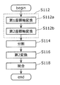
図14は、本発明の実施の形態2に係る逆変換部330における逆変換処理の一例を示すフローチャートである。
FIG. 14 is a flowchart showing an example of the inverse transform process in the inverse transform unit 330 according to Embodiment 2 of the present invention.
これらを用いて、逆変換処理について説明する。
Using these, the inverse conversion process will be described.
まず、図14に示すように、分割部400は、分割統合情報を取得する(ステップS231)。そして、分割部400は、上記で説明した復号変換出力信号y^nを、低周波数帯域を含む第2復号変換出力信号y^2
mと、高周波数帯域を含む第2復号部分信号y^1H
n-mとに分割する(ステップS232)。具体的には、分割部400は、分割統合情報に基づいて、第2復号変換出力信号y^2
mの相関エネルギーが、第2復号部分信号y^1H
n-mの相関エネルギーよりも大きくなるように、復号変換出力信号y^nの分割を行う。
First, as illustrated in FIG. 14, the dividing unit 400 acquires division integration information (step S <b> 231). Then, the dividing unit 400 converts the decoded converted output signal y n described above into the second decoded converted output signal y 2 m including the low frequency band and the second decoded partial signal y 1 H including the high frequency band. Divide into nm (step S232). Specifically, the dividing unit 400 has the correlation energy of the second decoded transform output signal y 2 m larger than the correlation energy of the second decoded partial signal 信号1H nm based on the division integration information. In this way, the decoded conversion output signal y n is divided.
なお、分割統合情報は、実施の形態1で説明したものと同様であり、分割統合情報の取得とは、予め定められたメモリ等に保存されたものを読み出してもよいし、復号変換出力信号y^2
mに応じて動的に決定してもよい。
Note that the division integration information is the same as that described in the first embodiment, and the acquisition of division integration information may be read out from a predetermined memory or the like, or a decoded conversion output signal it may be dynamically determined in accordance with the y ^ 2 m.
次に、第2逆変換部410は、第2逆変換に用いる第2逆変換係数を取得する(ステップS233)。第2逆変換係数で構成される第2逆変換行列は、実施の形態1で説明した第2変換の変換係数の逆行列又はそれに近似した行列である。この第2逆変換係数は、実施の形態1と同様に例えばKLTを用いて、第2復号変換出力信号y^2
mを含む集合SDに基づいて求めてもよいし、符号化装置での第2変換に用いられた第2変換係数から求めてもよい。
Next, the second inverse transform unit 410 acquires a second inverse transform coefficient used for the second inverse transform (step S233). The second inverse transformation matrix configured by the second inverse transformation coefficient is the inverse matrix of the transformation coefficient of the second transformation described in the first embodiment or a matrix approximated thereto. This second inverse transform coefficient may be obtained based on the set S D including the second decoded transform output signal ^ 2 m using, for example, KLT as in the first embodiment, You may obtain | require from the 2nd conversion coefficient used for 2nd conversion.
次に、第2逆変換部410は、決定された第2逆変換係数で構成される第2逆変換行列を用いて、第2復号変換出力信号y^2
mに第2逆変換を行うことで、第1復号部分信号y^1L
mを生成する(ステップS234)。そして、統合部420は、第1復号部分信号y^1L
mと、第2復号部分信号y^1H
n-mとを統合することで、第1復号変換出力信号y^1
nを生成する(ステップS236)。
Next, the second inverse transform unit 410 performs the second inverse transform on the second decoded transform output signal ^ 2 m using the second inverse transform matrix composed of the determined second inverse transform coefficients. Thus, the first decoded partial signal ^ 1L m is generated (step S234). Then, the integration unit 420 integrates the first decoded partial signal ^ 1L m and the second decoded partial signal ^ 1H n−m to generate the first decoded converted output signal y 1 n ( Step S236).
次に、第1逆変換部430は、第1逆変換に用いる第1逆変換係数を取得する(ステップS237)。第1逆変換係数で構成される第1逆変換行列は、実施の形態1で説明した第1変換の変換係数の逆行列又はそれに近似した行列である。この第1逆変換係数は、実施の形態1と同様に例えばKLTを用いて、第1復号変換出力信号y^1
nを含む集合SEに基づいて求めてもよいし、符号化装置での第1変換に用いられた第1変換係数から求めてもよい。このような逆変換係数の算出は以下の実施の形態でも同様に行ってよい。
Next, the first inverse transform unit 430 acquires a first inverse transform coefficient used for the first inverse transform (step S237). The first inverse transformation matrix configured by the first inverse transformation coefficient is the inverse matrix of the transformation coefficient of the first transformation described in the first embodiment or a matrix approximated thereto. This first inverse transform coefficient may be obtained based on the set S E including the first decoded transform output signal ^ 1 n using, for example, KLT as in the first embodiment, You may obtain | require from the 1st conversion coefficient used for the 1st conversion. Such calculation of the inverse transform coefficient may be performed similarly in the following embodiments.
第1逆変換部430は、決定された第1逆変換係数で構成される第1逆変換行列を用いて、第1復号変換出力信号y^1
nに第1逆変換を行うことで、復号信号x^nを生成する(ステップS238)。
The first inverse transform unit 430 performs the first inverse transform on the first decoded transform output signal ^ 1 n using the first inverse transform matrix composed of the determined first inverse transform coefficients, thereby decoding A signal x ^ n is generated (step S238).
なお、集合SDと集合SEは、実施の形態1の集合SCと集合SAの関係にあり、集合SDのほうが集合SEよりも含むサンプル数が少ない小さな集合である。以上のようにして、本発明の実施の形態2に係る逆変換部330を備えた復号装置300は、実施の形態1と同様に、高効率な変換と、演算量及びデータ量の削減とを両立させることができる。
Note that the set S D and the set S E are in the relationship between the set S C and the set S A in the first embodiment, and the set S D is a smaller set with a smaller number of samples than the set S E. As described above, the decoding apparatus 300 including the inverse transform unit 330 according to Embodiment 2 of the present invention performs high-efficiency conversion, and reduces the amount of computation and data, as in Embodiment 1. Both can be achieved.
なお、第2復号変換出力信号y^2
mと第1復号部分信号y^1L
mとのそれぞれについて、次元の並び替えを分割部400と統合部420とが行うこととしたが、それぞれの並び替えを第2逆変換部410が行う構成であってもよい。つまり、分離型の変換を用いてもよいし、図8(b)で示すような対角要素は1で非対角要素は0という行を含む変換行列A4を用いてもよい。また、復号の対象が、音声データ等の一次元信号の場合、あるいは、多次元信号を分離型で構成する場合の各次元の信号は一次元信号と見なせるため、逆変換部330に入力される復号変換出力信号y^nは一次元であり、前述の次元の並び替え(分割部400における一次元信号への並び替え、及び、統合部420における元の次元への並び替え)の処理は不要となる。
Note that the division unit 400 and the integration unit 420 perform the dimensional rearrangement on each of the second decoded conversion output signal ^ 2 m and the first decoded partial signal ^ 1L m. A configuration in which the second inverse conversion unit 410 performs the replacement may be used. That is, a separation type conversion may be used, or a conversion matrix A 4 including a row of 1 for diagonal elements and 0 for non-diagonal elements as shown in FIG. In addition, when a decoding target is a one-dimensional signal such as audio data, or when a multi-dimensional signal is configured as a separation type, each dimensional signal can be regarded as a one-dimensional signal and is input to the inverse transform unit 330. The decoding conversion output signal y ^ n is one-dimensional, and the above-described dimension rearrangement (rearrangement to the one-dimensional signal in the dividing unit 400 and rearrangement to the original dimension in the integrating unit 420) is unnecessary. It becomes.
以上のように、本発明の実施の形態2に係る復号装置300は、符号化信号にエントロピー復号及び逆量子化を行うことで生成される復号変換出力信号の一部である第2復号変換出力信号に第2逆変換を行い、第2逆変換後の信号と、復号変換出力信号の残りの部分である第2復号部分信号とを含む第1復号変換出力信号に第1逆変換を行うことを特徴とする。これにより、本発明の実施の形態2に係る復号装置300によれば、入力信号の統計的性質に基づいて計算される逆変換係数を用いる逆変換において、変換の演算量の削減、及び、逆変換行列の要素数の削減を実現することができる。また、実施の形態1に示す符号化装置100のように、入力信号の統計的性質に基づいて計算される変換係数を用いる変換を含む2段階の変換を行うことで生成された符号化信号を正しく復号することができる。
As described above, decoding apparatus 300 according to Embodiment 2 of the present invention provides the second decoded transform output that is a part of the decoded transform output signal generated by performing entropy decoding and inverse quantization on the encoded signal. Performing a second inverse transform on the signal and performing a first inverse transform on the first decoded transform output signal including the signal after the second inverse transform and the second decoded partial signal which is the remaining portion of the decoded transformed output signal It is characterized by. Thereby, according to decoding apparatus 300 according to Embodiment 2 of the present invention, in the inverse transformation using the inverse transformation coefficient calculated based on the statistical properties of the input signal, the amount of transformation computation is reduced and the inverse Reduction of the number of elements of the transformation matrix can be realized. Further, like the encoding device 100 shown in the first embodiment, an encoded signal generated by performing two-stage conversion including conversion using a conversion coefficient calculated based on statistical properties of an input signal is used. It can be decoded correctly.
なお、上記の実施の形態2に係る復号装置300では、復号変換出力信号y^nを第2復号変換出力信号y^2
mと第2復号部分信号y^1H
n-mとに分割し、第2逆変換後に統合するが、明示的に分割しなくてもよい。すなわち、復号変換出力信号y^nのうち、第2逆変換を実行する対象となる部分を決定すればよい。例えば、第2逆変換の際に、図8(b)で示すような対角要素は1で非対角要素は0という行を含む変換行列A4を用いることで、分割と統合とを実質的に第2逆変換の際に行うことができる。
In the decoding apparatus 300 according to Embodiment 2 described above, the decoded converted output signal y ^ n is divided into the second decoded converted output signal y ^ 2 m and the second decoded partial signal y ^ 1H nm , Although integration is performed after the second inverse transformation, it is not necessary to explicitly divide. That is, it is only necessary to determine a portion to be subjected to the second inverse transformation in the decoded transformation output signal ^ n . For example, at the time of the second inverse transformation, by using a transformation matrix A 4 including rows in which diagonal elements are 1 and non-diagonal elements are 0 as shown in FIG. In particular, this can be done during the second inverse transformation.
図15は、本発明の実施の形態2の変形例に係る復号装置300aの構成の一例を示すブロック図である。
FIG. 15 is a block diagram showing an exemplary configuration of a decoding apparatus 300a according to a modification of the second embodiment of the present invention.
復号装置300aは、エントロピー復号部310と、逆量子化部320と、逆変換部330aとを備える。なお、図11Aに示す復号装置300と同じ動作を行う処理部には、同じ符号を付しており、以下では説明を省略する。
The decoding device 300a includes an entropy decoding unit 310, an inverse quantization unit 320, and an inverse transform unit 330a. In addition, the same code | symbol is attached | subjected to the process part which performs the same operation | movement as the decoding apparatus 300 shown to FIG. 11A, and description is abbreviate | omitted below.
逆変換部330aは、第2逆変換部410aと、第1逆変換部430とを備える。つまり、逆変換部330aは、図11Bに示す逆変換部330と比較して、分割部400と、統合部420とを備えていない点と、さらに、第2逆変換部410の代わりに第2逆変換部410aを備える点とが異なっている。
The inverse transform unit 330a includes a second inverse transform unit 410a and a first inverse transform unit 430. That is, the inverse conversion unit 330a is not provided with the dividing unit 400 and the integration unit 420 as compared with the inverse conversion unit 330 illustrated in FIG. The difference is that the inverse conversion unit 410a is provided.
第2逆変換部410aは、第2逆変換行列を用いて、復号変換出力信号y^nの一部である第2復号変換出力信号y^2
mに第2逆変換を行うことで、第1復号部分信号y^1L
mを生成する。例えば、第2逆変換部410aは、復号変換出力信号y^nを構成する係数値のうち、第2逆変換の対象となる係数値を決定し、決定した係数値から構成される信号を第2復号変換出力信号y^2
mとして、第2逆変換を行う。より具体的には、第2逆変換部410aは、復号変換出力信号y^nを構成する複数の係数値のうち、所定の閾値より値の大きな係数値を含む信号を、第2復号変換出力信号y^2
mとして、第2変換を行う。
Second inverse transform unit 410a, by using a second inverse transformation matrix, a second inverse transform to the second decoded transformed signals y ^ 2 m, which is part of the decoded transform output signal y ^ n, the One decoded partial signal ^ 1L m is generated. For example, the second inverse transform unit 410a determines a coefficient value to be subjected to the second inverse transform among the coefficient values constituting the decoded transform output signal ^ n, and outputs a signal composed of the determined coefficient value. The second inverse transformation is performed as the 2 decoding transformation output signal ^ 2 m . More specifically, the second inverse transform unit 410a outputs a signal including a coefficient value having a value larger than a predetermined threshold among a plurality of coefficient values constituting the decoded converted output signal ^ n to the second decoded converted output. The second conversion is performed as the signal y 2 m .
例えば、第2逆変換部410aは、復号変換出力信号y^nのうち第2逆変換の対象とならない部分である第2復号部分信号y^1H
n-mに乗じられる第2逆変換係数の対角要素が1で非対角要素を0にすることで、実質的に第2復号変換出力信号y^2
mのみに、第2逆変換を行うことができる。
For example, the second inverse transform unit 410a may calculate the second inverse transform coefficient to be multiplied by the second decoded partial signal ^ 1H nm that is a portion not subjected to the second inverse transformation in the decoded transformed output signal ^ n . By setting the diagonal element to 1 and the non-diagonal element to 0, the second inverse transform can be performed substantially only on the second decoded transform output signal 信号2 m .
図16は、図15に示す復号装置300aの動作の一例を示すフローチャートである。
FIG. 16 is a flowchart showing an example of the operation of the decoding device 300a shown in FIG.
まず、エントロピー復号部310は、入力された符号化信号をエントロピー復号することで、復号量子化係数C^nを生成する(ステップS210)。次に、逆量子化部320は、復号量子化係数C^nを逆量子化することで、復号変換出力信号y^nを生成する(ステップS220b)。
First, the entropy decoding unit 310 generates a decoded quantized coefficient C ^ n by entropy decoding the input encoded signal (step S210). Next, the inverse quantization unit 320 generates a decoded transform output signal y ^ n by inversely quantizing the decoded quantized coefficient C ^ n (step S220b).
次に、逆変換部330aが、復号変換出力信号y^nを逆変換することで、復号信号を生成する(ステップS230a)。具体的には、まず、第2逆変換部410aは、復号変換出力信号y^nのうち、第2逆変換の対象となる部分である第2復号変換出力信号y^2
mを逆変換することで、第1復号部分信号y^1L
mを生成する(S234a)。そして、第2逆変換部410aは、生成した第1復号部分信号y^1L
mと、復号変換出力信号y^nのうち第2逆変換の対象とならなかった部分である第2復号部分信号y^1H
n-mとを含む第1復号変換出力信号y^1
nを出力する。
Next, the inverse conversion unit 330a generates a decoded signal by inversely converting the decoded conversion output signal y ^ n (step S230a). More specifically, first, second inverse transform unit 410a, among the decoded transform output signal y ^ n, inversely transforms the second decoded transformed signals y ^ 2 m is subject to parts of the second inverse transformation Thus, the first decoded partial signal y 1 L m is generated (S234a). The second inverse transform unit 410a then generates a second decoded partial signal that is a portion that has not been subjected to the second inverse transformation in the generated first decoded partial signal y 1L m and the decoded transformed output signal ^ n. A first decoded conversion output signal y ^ 1 n including y ^ 1H nm is output.
最後に、第1逆変換部430は、第1逆変換行列を用いて第1復号変換出力信号y^1
nに第1逆変換を行うことで、復号信号x^nを生成する(S238)。
Finally, the first inverse transformation unit 430, by performing the first inverse transformation on the first decoded transformed signals y ^ 1 n by using the first inverse transformation matrix to generate a decoded signal x ^ n (S238) .
以上のように、実施の形態2の変形例に係る復号装置300aによっても、演算量の増加及び逆変換係数のデータ量の増加を抑制するために、2段階の変換が行われた符号化信号を復号することができる。
As described above, even in the decoding apparatus 300a according to the modification of the second embodiment, an encoded signal that has been subjected to two-stage transformation in order to suppress an increase in the calculation amount and an increase in the data amount of the inverse transform coefficient. Can be decrypted.
(実施の形態3)
本発明の実施の形態3に係る符号化装置及び符号化方法は、音声データ、静止画像データ、動画像データなど符号化対象となる信号を、複数種類の変換の組み合わせによって変換を行う変換部及び変換方法を備える。本発明の実施の形態3に係る符号化装置及び符号化方法は、変換入力信号として、符号化対象信号(入力信号)と予測信号との差分である予測誤差信号に対して、2段階の変換を行うことを特徴とする。
(Embodiment 3)
An encoding device and an encoding method according to Embodiment 3 of the present invention include a conversion unit that converts a signal to be encoded, such as audio data, still image data, and moving image data, by a combination of a plurality of types of conversions; A conversion method is provided. The encoding apparatus and encoding method according to Embodiment 3 of the present invention perform two-stage conversion on a prediction error signal that is a difference between a signal to be encoded (input signal) and a prediction signal as a conversion input signal. It is characterized by performing.
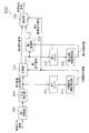
図17は、本発明の実施の形態3に係る符号化装置500の構成の一例を示すブロック図である。図17に示すように、本発明の実施の形態3に係る符号化装置500は、減算器505と、変換部510と、量子化部120と、エントロピー符号化部130と、逆量子化部540と、逆変換部550と、加算器560と、メモリ570と、予測部580と、制御部590とを備える。なお、図3に示す実施の形態1に係る符号化装置100と同じ構成については、同じ符号を付し、以下では説明を省略する。
FIG. 17 is a block diagram showing an example of the configuration of encoding apparatus 500 according to Embodiment 3 of the present invention. As shown in FIG. 17, coding apparatus 500 according to Embodiment 3 of the present invention includes subtractor 505, transform unit 510, quantization unit 120, entropy coding unit 130, and inverse quantization unit 540. A reverse conversion unit 550, an adder 560, a memory 570, a prediction unit 580, and a control unit 590. Note that the same components as those of coding apparatus 100 according to Embodiment 1 shown in FIG. 3 are denoted by the same reference numerals, and description thereof is omitted below.
減算器505は、符号化対象である入力信号と、以前の符号化対象信号から生成された予測信号との差分(予測誤差)を算出する。算出された予測誤差を示す信号が、変換入力信号として、変換部510に入力される。
The subtracter 505 calculates a difference (prediction error) between the input signal to be encoded and the prediction signal generated from the previous encoding target signal. A signal indicating the calculated prediction error is input to the conversion unit 510 as a conversion input signal.
変換部510は、実施の形態1で説明した変換部110と同様に、変換入力信号に対して2段階の変換を行う。すなわち、変換部510は、変換入力信号に第1変換を行うことで、第1変換出力信号を生成し、生成した第1変換出力信号の一部である第1部分信号に第2変換を行うことで、第2変換出力信号を生成する。そして、変換部510は、生成した第2変換出力信号と、第1変換出力信号のうち第1部分信号以外の部分である第2部分信号とを含む変換出力信号を量子化部120に出力する。変換部510の詳細については、後で説明する。ここでは、変換部510には、変換入力信号として、予測誤差画像を示す信号が入力される。
The conversion unit 510 performs two-stage conversion on the conversion input signal, similarly to the conversion unit 110 described in the first embodiment. That is, the conversion unit 510 performs a first conversion on the converted input signal to generate a first converted output signal, and performs a second conversion on the first partial signal that is a part of the generated first converted output signal. Thus, the second conversion output signal is generated. Then, the conversion unit 510 outputs a converted output signal including the generated second converted output signal and the second partial signal that is a portion other than the first partial signal in the first converted output signal to the quantization unit 120. . Details of the conversion unit 510 will be described later. Here, the conversion unit 510 receives a signal indicating a prediction error image as a conversion input signal.
逆量子化部540は、量子化部120によって生成された量子化係数を逆量子化することで、復号変換出力信号を生成する。復号変換出力信号は、変換部510によって生成された変換出力信号に相当する。
The inverse quantization unit 540 generates a decoded conversion output signal by inversely quantizing the quantization coefficient generated by the quantization unit 120. The decoded conversion output signal corresponds to the conversion output signal generated by the conversion unit 510.
逆変換部550は、逆量子化部540によって生成された復号変換出力信号を逆変換することで、復号変換入力信号を生成する。復号変換入力信号は、減算器505によって生成された変換入力信号に相当する。
The inverse transform unit 550 inversely transforms the decoded conversion output signal generated by the inverse quantization unit 540, thereby generating a decoded conversion input signal. The decoded converted input signal corresponds to the converted input signal generated by the subtracter 505.
加算器560は、逆変換部550によって生成された復号変換入力信号と、以前の符号化対象信号から生成された予測信号とを加算することで、復号信号を生成する。
The adder 560 generates a decoded signal by adding the decoded conversion input signal generated by the inverse conversion unit 550 and the prediction signal generated from the previous encoding target signal.
メモリ570は、生成された復号信号を格納するための記憶部の一例である。
The memory 570 is an example of a storage unit for storing the generated decoded signal.
予測部580は、復号信号を用いて、符号化対象信号の予測を行うことで、予測信号を生成する。具体的には、予測部580は、所定の符号化パラメータに基づいて、符号化対象である入力画像に含まれる符号化対象ブロックの予測画素(予測信号)を生成する。減算器505では、符号化対象ブロックの画素と予測画素との差分である予測誤差画像が生成される。
The prediction unit 580 generates a prediction signal by predicting the encoding target signal using the decoded signal. Specifically, the prediction unit 580 generates a prediction pixel (prediction signal) of an encoding target block included in an input image that is an encoding target, based on a predetermined encoding parameter. The subtracter 505 generates a prediction error image that is a difference between the pixel of the encoding target block and the prediction pixel.
制御部590は、局所情報に基づいて、変換部510の動作を制御するための制御信号を出力する。局所情報は、例えば、変換係数及び分割統合情報に対応付けられたインデックス、あるいは、予測モードなどを示す情報である。制御部590は、これらの局所情報に基づいて、変換係数及び分割統合情報を決定し、決定した係数及び情報を示す制御情報を変換部510に出力する。
Control unit 590 outputs a control signal for controlling the operation of conversion unit 510 based on the local information. The local information is, for example, information indicating an index associated with a transform coefficient and division integration information, a prediction mode, or the like. The control unit 590 determines conversion coefficients and division integration information based on the local information, and outputs control information indicating the determined coefficients and information to the conversion unit 510.
本発明の実施の形態3に係る符号化装置500では、制御部590からの制御に基づいて、第2変換の際に、第1部分信号として、第1変換出力信号のうち第2変換の対象となる範囲と、第2変換係数との少なくとも一方を、時間的又は空間的に適応的に決定する。例えば、所定の符号化パラメータに基づいて、第1部分信号として、第1変換出力信号のうち第2変換の対象となる範囲と、第2変換係数との少なくとも一方を決定する。
In encoding apparatus 500 according to Embodiment 3 of the present invention, the second conversion target of the first conversion output signal is used as the first partial signal in the second conversion based on the control from control unit 590. And at least one of the second conversion coefficient is determined adaptively in terms of time or space. For example, based on a predetermined encoding parameter, at least one of the range to be subjected to the second conversion and the second conversion coefficient in the first conversion output signal is determined as the first partial signal.
なお、メモリ570は、符号化対象信号とそれ以前の対象信号から生成された予測信号との比較を可能にする遅延部として動作する。量子化部120の量子化処理によって情報量が圧縮される(情報の損失が発生する)ので、符号化信号に符号化された情報を取り出すために、逆量子化部540は、量子化係数を逆量子化することで、復号変換出力信号を生成し、逆変換部550は、復号変換出力信号を逆変換することで、復号変換入力信号を生成する。
Note that the memory 570 operates as a delay unit that enables comparison between an encoding target signal and a prediction signal generated from a previous target signal. Since the amount of information is compressed by the quantization process of the quantization unit 120 (information loss occurs), the inverse quantization unit 540 extracts the quantization coefficient to extract the information encoded in the encoded signal. By performing inverse quantization, a decoded conversion output signal is generated, and the inverse conversion unit 550 generates a decoded conversion input signal by performing inverse conversion on the decoded conversion output signal.
なお、逆変換部550の逆変換処理は、変換部510の変換処理と逆変換の関係が成り立つ必要がある。ただし、演算に必要なビット長を抑えるための乗算の簡易化や丸め処理の挿入により、変換処理及び逆変換処理は厳密に行列で表現されない場合もあり、また、変換部510の変換処理と逆変換部550の逆変換処理とは、厳密な逆変換の関係を満たさないように設計する場合もある。
It should be noted that the inverse transformation process of the inverse transformation unit 550 needs to satisfy the relationship between the transformation process of the transformation unit 510 and the inverse transformation. However, due to simplification of multiplication for suppressing the bit length necessary for calculation and insertion of a rounding process, the conversion process and the inverse conversion process may not be expressed strictly as a matrix, and the process is reverse to the conversion process of the conversion unit 510. The inverse transformation process of the conversion unit 550 may be designed so as not to satisfy a strict inverse transformation relationship.
なお、音声又はオーディオのデータを符号化する場合には入力信号は一次元であり、静止画像又は動画像のデータを符号化する場合には入力信号は二次元となる。
Note that when encoding voice or audio data, the input signal is one-dimensional, and when encoding still image or moving image data, the input signal is two-dimensional.
次に、図18を用いて、本発明の実施の形態3に係る符号化装置500が実行する符号化処理を説明する。図18は、本発明の実施の形態3に係る符号化装置500の動作の一例を示すフローチャートである。
Next, an encoding process executed by the encoding apparatus 500 according to Embodiment 3 of the present invention will be described with reference to FIG. FIG. 18 is a flowchart showing an example of the operation of coding apparatus 500 according to Embodiment 3 of the present invention.
まず、符号化装置500に符号化対象信号(入力信号)が入力されると、予測部580は、メモリ570に格納された符号化済み信号(復号信号)を用いて予測信号を生成する。そして、減算器505は、入力信号と予測信号との誤差である予測誤差信号を生成する(ステップS305)。なお、予測誤差信号ではなく、入力信号を直接変換する場合には、ステップS305の予測誤差信号を生成するステップは省略される。
First, when an encoding target signal (input signal) is input to the encoding device 500, the prediction unit 580 generates a prediction signal using the encoded signal (decoded signal) stored in the memory 570. Then, the subtracter 505 generates a prediction error signal that is an error between the input signal and the prediction signal (step S305). Note that when the input signal is directly converted instead of the prediction error signal, the step of generating the prediction error signal in step S305 is omitted.
減算器505によって生成された予測誤差信号又は入力信号は、変換部510に入力される。変換へ入力される点のベクトル、すなわち、予測誤差信号を、変換入力(Transform Input)信号xnとする(式4参照)。なお、多くの圧縮符号化において予測が行われるため、変換入力信号xnは、予測誤差(Prediction Error)であることが多いが、伝送路にエラーが混入する場合を想定して予測を行わない場合、あるいは、十分にエネルギーが小さい場合には予測を行わずに、符号化対象信号(Original Signal)、すなわち、入力信号を直接に変換へ入力する場合もある。
The prediction error signal or input signal generated by the subtractor 505 is input to the conversion unit 510. A vector of points input to the transformation, that is, a prediction error signal is defined as a transformation input signal x n (see Equation 4). Since prediction is performed in many compression encodings, the converted input signal xn is often a prediction error, but is not predicted on the assumption that an error is mixed in the transmission path. In some cases, or when the energy is sufficiently small, the signal to be encoded (original signal), that is, the input signal, may be directly input to the conversion without performing prediction.
変換部510は、変換入力信号xnを、ある変換Tで変換することで、変換出力(Transform Output)信号ynを生成する(式5参照)(ステップS110)。また、変換出力信号(変換出力ベクトル)ynは、単に係数(Coefficient)と呼ばれることもある。
Conversion unit 510, a conversion input signal x n, to convert a certain transformation T, which generates conversion output (Transform Output) signal y n (see formula 5) (step S110). The conversion output signal (converted output vector) y n is sometimes simply referred to as a coefficient (Coefficient).
次に、量子化部120は、変換出力信号ynを量子化することで、量子化係数(Quantized Coefficient)Cnを生成する(ステップS120)。量子化部120が行う量子化処理は、丸めオフセットaを加算後に一様量子化ステップsで除算する処理であり、式6のように表現される。a及びsは、符号化装置500において高能率符号化のために制御される。
Then, the quantization unit 120, by quantizing the converted output signal y n, and generates a quantization coefficient (Quantized Coefficient) C n (step S120). The quantization process performed by the quantization unit 120 is a process of adding the rounding offset a and then dividing it by the uniform quantization step s, and is expressed as Expression 6. a and s are controlled by the encoding apparatus 500 for high-efficiency encoding.
次に、エントロピー符号化部130は、量子化係数Cnをエントロピー符号化することで、符号化信号を生成する(ステップS130)。生成された符号化信号は、復号装置へ送られる。
Next, the entropy encoding unit 130 generates an encoded signal by entropy encoding the quantization coefficient C n (step S130). The generated encoded signal is sent to the decoding device.
次に、逆量子化部540は、式7のように、量子化係数Cnに逆量子化を行うことで、復号変換出力(Decoded Transform Output)信号y^nを生成する(ステップS340)。
Next, the inverse quantization unit 540 generates a decoded transformed output signal y ^ n by performing inverse quantization on the quantized coefficient C n as shown in Equation 7 (step S340).
なお、データ量を大幅に削減する代わりに元のデータへ完全に復元することはできないロッシー符号化では、量子化処理によって情報量が失われるため、復号変換出力信号y^nと変換出力信号ynとは一致しない。つまり、復号変換出力信号y^nには、量子化による歪みが混入していることから、変換の前に予測をしている場合には、復号変換出力信号y^nは、量子化予測誤差(Quantized Prediction Error)と呼ばれることもある。なお、ロッシー符号化の場合でも十分なデータ量で符号化する場合には、情報はあまり失われず、y^nとynとはほぼ一致する。
Note that in lossy coding that cannot be completely restored to the original data instead of greatly reducing the amount of data, the amount of information is lost due to the quantization process, so the decoded transformed output signal y n and the transformed output signal y. Does not match n . That is, the decoded transform output signal y ^ n, since the distortion due to quantization is mixed, if you predicted before the conversion, the decoded converted output signal y ^ n the quantization prediction error It may also be called (Quantized Prediction Error). Even in the case of lossy encoding, when encoding is performed with a sufficient amount of data, information is not lost so much and ^ n and y n substantially coincide.
次に、逆変換部550は、式8のように、復号変換出力信号y^nに逆変換T-1を行うことで、復号変換入力ベクトルx^nを生成する(ステップS350)。
Next, the inverse transform unit 550 performs the inverse transform T −1 on the decoded transform output signal ^ n as shown in Equation 8, thereby generating the decoded transform input vector x n n (step S350).
次に、加算器560が、上記予測信号と復号変換入力信号とを加算することで、復号信号を生成する。そして、加算器560は、生成した復号信号をメモリ570に格納して、次のタイミングにて参照できるようにする(ステップS360)。
Next, the adder 560 adds the prediction signal and the decoded conversion input signal to generate a decoded signal. Then, the adder 560 stores the generated decoded signal in the memory 570 so that it can be referred to at the next timing (step S360).
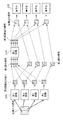
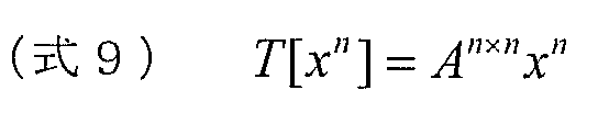
なお、変換T及び逆変換T-1はそれぞれ式9及び式10に示すようなn×nの大きさの変換行列A及びBとの行列積で表現される。
Note that the transformation T and the inverse transformation T −1 are expressed by matrix products with transformation matrices A and B having a size of n × n as shown in Equation 9 and Equation 10, respectively.
一般的な変換(いわゆる直交変換)では、変換行列Bは、Aの逆行列であり転置行列(B=AT)である。ただし、これに限るものではなく、符号化装置500内の逆変換T-1の演算量を抑えるために、BはAの厳密な逆行列や厳密な転置行列とならない場合もある。また、双直交(Biorthogonal)変換と呼ばれる、厳密には直交をしていない変換A及びその逆変換Bであってもよい。
In a general transformation (so-called orthogonal transformation), the transformation matrix B is an inverse matrix of A and a transposed matrix (B = A T ). However, the present invention is not limited to this, and B may not be a strict inverse matrix or a strict transpose matrix of A in order to suppress the amount of computation of the inverse transform T −1 in the encoding apparatus 500. Further, it may be a transformation A called bi-orthogonal transformation, which is not strictly orthogonal, and its inverse transformation B.
式9における、変換入力xnに対する変換行列An×nの行列積は、式11で表現される。変換行列の乗算回数及び変換行列の要素数は、n^2である。
The matrix product of the transformation matrix A n × n with respect to the transformation input x n in Equation 9 is expressed by Equation 11. The number of multiplications of the transformation matrix and the number of elements of the transformation matrix are n ^ 2.
次に、本発明の実施の形態3に係る変換部510の構成及び動作について説明する。図19は、本発明の実施の形態3に係る変換部510の詳細な構成の一例を示すブロック図である。
Next, the configuration and operation of the conversion unit 510 according to Embodiment 3 of the present invention will be described. FIG. 19 is a block diagram showing an example of a detailed configuration of conversion unit 510 according to Embodiment 3 of the present invention.
図19に示すように、変換部510は、第1変換部200と、第1メモリ601と、第1変換係数導出部202と、分割部210と、第2メモリ611と、分割統合情報算出部612と、第2変換部220と、第3メモリ621と、第2変換係数導出部222と、統合部230とを有する。なお、図3に示す変換部110と同じ構成については、同じ符号を付している。
As illustrated in FIG. 19, the conversion unit 510 includes a first conversion unit 200, a first memory 601, a first conversion coefficient derivation unit 202, a division unit 210, a second memory 611, and a division integration information calculation unit. 612, a second conversion unit 220, a third memory 621, a second conversion coefficient derivation unit 222, and an integration unit 230. In addition, the same code | symbol is attached | subjected about the same structure as the conversion part 110 shown in FIG.
変換部510に入力された変換入力信号xnは、第1メモリ601と第1変換部200とに入力される。
The conversion input signal xn input to the conversion unit 510 is input to the first memory 601 and the first conversion unit 200.
第1メモリ601は、複数個の変換入力信号xnに関する情報を記憶するためのメモリである。
The first memory 601 is a memory for storing information related to a plurality of converted input signals xn .
第1変換係数導出部202は、第1メモリ601の情報から第1変換T1に用いる第1変換行列A1
nを構成する第1変換係数を生成し、生成した第1変換係数を第1変換部200へ出力する。
The first transform coefficient deriving unit 202 generates a first transform coefficient constituting the first transform matrix A 1 n used for the first transform T 1 from the information in the first memory 601 and uses the generated first transform coefficient as the first transform coefficient. The data is output to the conversion unit 200.
第1変換部200は、入力された変換入力信号xnに対して、第1変換係数導出部202によって算出された第1変換係数で構成される第1変換行列A1
nを用いて第1変換T1を行うことで、第1変換出力信号y1
nを生成する。第1変換出力信号y1
nは、第2メモリ611及び分割部210に入力される。
The first conversion unit 200 uses the first conversion matrix A 1 n configured by the first conversion coefficient calculated by the first conversion coefficient derivation unit 202 for the input conversion input signal x n . by performing the conversion T 1, to generate a first conversion output signal y 1 n. The first converted output signal y 1 n is input to the second memory 611 and the dividing unit 210.
第2メモリ611には、複数個の第1変換出力信号y1
nに関する情報を記憶するためのメモリである。
The second memory 611 is a memory for storing information related to a plurality of first converted output signals y 1 n .
分割統合情報算出部612は、第2メモリ611の情報から分割統合情報を生成し、生成した分割統合情報を分割部210及び統合部230へ出力する。分割統合情報は、第1変換出力信号y1
nのうち低域の成分を第1部分信号y1L
mへ、高域の成分を第2部分信号y1H
n-mへ分割するような分割の制御情報である。その他、エネルギーの大きな成分を第1部分信号y1L
mへ、エネルギーの小さな成分を第2部分信号y1H
n-mへ分割するような分割するような情報であってもよい。
The division integration information calculation unit 612 generates division integration information from the information in the second memory 611, and outputs the generated division integration information to the division unit 210 and the integration unit 230. Segmentation-concatenation information, the components of the low frequency of the first conversion output signal y 1 n to the first partial signal y 1L m, split so as to divide the components of the high frequency to the second partial signal y IH n-m Control information. In addition, the information may be divided such that a component having a large energy is divided into the first partial signal y 1L m and a component having a small energy is divided into the second partial signal y 1H nm .
分割部210は、第1変換出力信号y1
nを、分割統合情報に基づいて、m点の第1部分信号y1L
mと、n-m点の第2部分信号y1H
n-mへ分割する(ここで、mはnより小さな自然数である)。つまり、分割部210は、n個の係数値から構成される第1変換出力信号y1
nを、m個の係数値から構成される第1部分信号y1L
mと、n-m個の係数値から構成される第2部分信号y1H
n-mとに分割する。第1部分信号y1L
mは、第3メモリ621及び第2変換部220に入力される。また、第2部分信号y1H
n-mは、統合部230に入力される。
Dividing unit 210 divides the first conversion output signal y 1 n, on the basis of the segmentation-concatenation information, the first partial signal y 1L m of m points, the n-m point to the second partial signal y IH n-m (Where m is a natural number smaller than n). That is, the dividing unit 210 converts the first converted output signal y 1 n composed of n coefficient values, the first partial signal y 1L m composed of m coefficient values, and n−m coefficients. The second partial signal y 1H nm is divided into numerical values. The first partial signal y 1L m is input to the third memory 621 and the second conversion unit 220. The second partial signal y 1H nm is input to the integration unit 230.
第3メモリ621は、複数個の第1部分信号y1L
mに関する情報を記憶するためのメモリである。
The third memory 621 is a memory for storing information related to a plurality of first partial signals y 1L m .
第2変換係数導出部222は、第3メモリ621の情報から第2変換T2に用いる第2変換行列A2
mを構成する第2変換係数を生成し、生成した第2変換係数を第2変換部220へ出力する。
The second transform coefficient deriving unit 222 generates a second transform coefficient that constitutes the second transform matrix A 2 m used for the second transform T 2 from the information in the third memory 621, and uses the generated second transform coefficient as the second transform coefficient. The data is output to the conversion unit 220.
第2変換部220は、第2変換係数導出部222によって算出された第2変換係数で構成される第2変換行列A2
mを用いて、第1部分信号y1L
mに第2変換T2を行うことで、第2変換出力信号y2
mを生成する。
Second conversion unit 220, by using the second transformation matrix A 2 m constituted by a second conversion coefficient calculated by the second conversion coefficient deriving unit 222, a second transformation T 2 to the first partial signal y 1L m To generate the second converted output signal y 2 m .
統合部230は、第2変換出力信号y2
mと第2部分信号y1H
n-mとを、分割統合情報に従って統合することで変換出力信号ynを生成する。なお、統合とは、分割の反対の処理である。
The integrating unit 230 generates the converted output signal y n by integrating the second converted output signal y 2 m and the second partial signal y 1H nm according to the division integration information. Note that integration is a process opposite to division.
第2変換係数導出部222によって決定される第2変換係数は、第1部分信号y1L
mに最適に設計された変換係数である。このため、第2変換行列A2
mを用いた第2変換T2は、第1変換出力信号y1
nに残された冗長性を削減できる変換であり、符号化信号の圧縮に寄与する効果をもたらす。
The second transform coefficient determined by the second transform coefficient deriving unit 222 is a transform coefficient designed optimally for the first partial signal y 1L m . For this reason, the second transformation T 2 using the second transformation matrix A 2 m is a transformation that can reduce the redundancy left in the first transformation output signal y 1 n , and contributes to the compression of the encoded signal. Bring.
また、分割部210が第1変換出力信号y1
nを分割することにより、第2変換部220への入力信号(つまり、第1部分信号)の点数(係数値の個数)を減らすことができる。点数が減ることにより、第2変換部220の演算量の削減効果、及び、第2変換部220の変換係数の総数(つまり、データ量)の削減効果が得られる。
Further, the dividing unit 210 divides the first converted output signal y 1 n , thereby reducing the number of points (number of coefficient values) of the input signal (that is, the first partial signal) to the second converting unit 220. . By reducing the number of points, an effect of reducing the amount of calculation of the second conversion unit 220 and an effect of reducing the total number of conversion coefficients (that is, the amount of data) of the second conversion unit 220 are obtained.
ここで、第1変換係数導出部202による第1変換係数の生成、及び、第2変換係数導出部222による第2変換係数の生成について述べる。これらの変換係数の生成には、例えば、上述したKLTを用いる。
Here, generation of the first transform coefficient by the first transform coefficient deriving unit 202 and generation of the second transform coefficient by the second transform coefficient deriving unit 222 will be described. For example, the above-described KLT is used to generate these conversion coefficients.
KLT(カルーネンレーベ変換)は、入力信号を含むある集合の統計的な性質に基づいて、入力信号を完全に無相関化できる周波数領域への変換を設計する手法である。具体的には、入力信号の分散共分散行列(Variance-covariance matrix)の非対角要素が0となるような変換を求めることであり、これは、分散共分散行列の固有値問題を解くことに等しい。導出した固有ベクトルが基底関数となり、固有値が変換係数の各成分の軸の大きさ(つまり、エネルギー)となる。固有値の値(分散、あるいは、エネルギー)の大きな軸から小さな軸へと変換係数を並べる。この順で並べることにより、例えば、変換入力信号がn点のベクトルであるとすると、変換出力信号のn点のベクトルのうち、i番目の要素(1≦i<n)とj番目(i<j≦n)の要素とのエネルギーを比較すると、i番目の要素のエネルギーは、j番目の要素のエネルギーよりも大きくなる(大きくなるように変換係数を設計できる)。
KLT (Karunen-Leve Transform) is a technique for designing a conversion to a frequency domain that can completely decorrelate an input signal based on the statistical properties of a set including the input signal. Specifically, the transformation is such that the off-diagonal elements of the variance-covariance matrix of the input signal are 0, which is to solve the eigenvalue problem of the variance-covariance matrix. equal. The derived eigenvector becomes a basis function, and the eigenvalue becomes the axis size (that is, energy) of each component of the transform coefficient. The conversion coefficients are arranged from a large axis of eigenvalue (dispersion or energy) to a small axis. By arranging in this order, for example, if the converted input signal is an n-point vector, the i-th element (1 ≦ i <n) and the j-th (i <n) of the n-point vectors of the converted output signal. Comparing the energy with the element of j ≦ n), the energy of the i-th element is larger than the energy of the j-th element (the conversion coefficient can be designed to be larger).
本発明において、低周波数帯域、及び、高周波数帯域という表現を使うとき、それらは、それぞれ、相対的に小さい番号を持つ要素、相対的に大きな番号を持つ要素に対応しており、厳密に区切りがどこにあるかを規定するものではない。本発明は、変換及び逆変換等にかかるリソース(演算量や使用メモリ量)の削減を主な目的としているが、リソースと変換性能とには広い意味でトレードオフの関係があり、本発明が使われる方法や装置の目的に応じて設定されるものである。
In the present invention, when the expressions low frequency band and high frequency band are used, they correspond to an element having a relatively small number and an element having a relatively large number, respectively, and are strictly separated. It does not prescribe where is. The main purpose of the present invention is to reduce resources (computation amount and memory usage) related to conversion and inverse conversion, but there is a trade-off relationship between resources and conversion performance in a broad sense. It is set according to the method used and the purpose of the apparatus.
しかし、従来技術の課題で言及したように、変換係数を導出した際に参照した集合とは異なる統計的性質を持つ集合が入力されると、導出した変換係数を用いた変換は最適ではなくなる。これに対して、入力信号の性質に応じて、入力信号が入力される度に変換係数を導出すると、変換係数のデータ量が膨大となる。
However, as mentioned in the problem of the prior art, if a set having statistical properties different from the set referred to when the transform coefficient is derived is input, the transform using the derived transform coefficient is not optimal. On the other hand, if a conversion coefficient is derived every time an input signal is input according to the nature of the input signal, the data amount of the conversion coefficient becomes enormous.
この課題に対し、本実施の形態では、複数の変換を用いる。すなわち、第1変換において、より大きな集合SAの統計的性質に応じて最適に導出された変換係数で構成される変換行列を用いて変換し、第2変換において、より小さな集合SBの(第1変換出力信号の)統計的性質に応じて、最適に導出された変換係数で構成される変換行列を用いて変換する。
In this embodiment, a plurality of conversions are used for this problem. That is, in the first transformation, transformation is performed using a transformation matrix composed of transformation coefficients that are optimally derived according to the statistical properties of the larger set S A , and in the second transformation, the smaller set S B ( Conversion is performed using a conversion matrix composed of optimally derived conversion coefficients according to the statistical properties of the first converted output signal.
なお、本発明の実施の形態3に係る符号化装置500は、第2変換係数を導出する際に、入力信号の特徴を解析する局所集合判定部を備えていてもよい。つまり、本発明の実施の形態3に係る符号化装置500は、変換部510の代わりに、図20に示す変換部510aを備えていてもよい。変換部510aは、図20に示すように、局所集合判定部623を備える。
Note that the encoding apparatus 500 according to Embodiment 3 of the present invention may include a local set determination unit that analyzes the characteristics of the input signal when deriving the second transform coefficient. That is, encoding apparatus 500 according to Embodiment 3 of the present invention may include conversion unit 510a shown in FIG. 20 instead of conversion unit 510. As illustrated in FIG. 20, the conversion unit 510 a includes a local set determination unit 623.
局所集合判定部623は、変換入力信号xnの特徴を解析し、解析結果に基づいて第2変換係数導出部222の制御を行う。なお、図20には図示していないが、局所集合判定部623は、図19に示す分割統合情報算出部612の制御を行ってもよい。局所集合判定部623の具体的な処理については、図21を用いて、以下に説明する。
The local set determination unit 623 analyzes the characteristics of the transform input signal xn and controls the second transform coefficient derivation unit 222 based on the analysis result. Although not shown in FIG. 20, the local set determination unit 623 may control the division integration information calculation unit 612 shown in FIG. Specific processing of the local set determination unit 623 will be described below with reference to FIG.
図21は、本発明の実施の形態3に係る変換部510aにおける変換係数の導出の一例を概念的に示す図である。
FIG. 21 is a diagram conceptually illustrating an example of the derivation of the transform coefficient in the transform unit 510a according to Embodiment 3 of the present invention.
変換入力信号xnは、大きな集合SAに属し、かつ、より小さな集合SB(1)とSB(2)のいずれかに属する場合を想定する。なお、図21では、集合SBは集合SAに含まれるよう図示しているが、変換入力信号xnが集合SBに属し、集合SAに属さないというような、集合SBが集合SAに含まれない場合でも同様の導出方法が適用可能である。
It is assumed that the converted input signal x n belongs to a large set S A and belongs to one of the smaller sets S B (1) and S B (2) . In FIG 21, although the set S B are shown to be included in the set S A, is converted input signal x n belongs to the set S B, such that does not belong to the set S A, the set S B set A similar derivation method can be applied even when it is not included in SA.
第1変換部200が用いる第1変換係数は、第1変換係数導出部202によって生成される。第1変換係数導出部202は、より多くのサンプルを含む集合SAに基づいて、第1変換係数を最適化する。
The first conversion coefficient used by the first conversion unit 200 is generated by the first conversion coefficient derivation unit 202. First conversion coefficient deriving unit 202, based on a set S A containing more samples, to optimize the first transformation coefficient.
集合SAはより多くのサンプルを含むので、第1変換係数は、平均的に最適化され、個々の変換入力の違いの影響をあまり受けないようにできる。これによって、第1変換係数の更新頻度を抑えることができる。また、第1変換係数の更新を行う場合でも、変換係数の個々の値の変化量は小さくなるため、差分情報量を少なくできる。したがって、第1変換係数を復号装置に送信する場合の符号量を削減することができる。
Since the set S A includes more samples, the first transform coefficient can be optimized on the average and less sensitive to differences in individual transform inputs. Thereby, the update frequency of the first conversion coefficient can be suppressed. Even when the first transform coefficient is updated, the amount of difference information can be reduced because the change amount of each value of the transform coefficient is small. Therefore, it is possible to reduce the amount of codes when the first transform coefficient is transmitted to the decoding device.
第2変換係数は、変換入力が集合SB(1)とSB(2)のそれぞれに最適化して導出する。第2変換部220では、第2変換の対象となる第1部分信号の点数が、分割によって変換入力信号の点数よりも減らされているので、演算量と変換係数のデータ量とを削減できる。つまり、第2変換の対象となる第2変換部220への入力信号は、集合SB(1)、SB(2)に含まれる変換入力信号xnそのものではなく、第1変換出力信号y1
nの一部である第1部分信号y1L
mである。
The second transform coefficient is derived by optimizing the transform input for each of the sets SB (1) and SB (2) . In the second conversion unit 220, since the score of the first partial signal to be subjected to the second conversion is reduced by the division than the score of the converted input signal, the amount of calculation and the data amount of the conversion coefficient can be reduced. That is, the input signal to the second converter 220 to be the second transformation, the set S B (1), S B (2) to convert the input signal x n not itself included, first conversion output signal y 1 n is a first partial signal y 1L m which is a part of n .
局所集合判定部623は、変換入力信号xnの特徴を解析することで、小集合の統計的な変動を検出する。変動を検出すると、小集合に属する複数個のサンプルを決定し、第2変換係数導出部222へ通知する。あるいは、局所集合判定部623は、変換入力信号xnが、予め定めた小集合のいずれに属するかを判定してもよい。
The local set determination unit 623 detects the statistical variation of the small set by analyzing the characteristics of the converted input signal xn . When the change is detected, a plurality of samples belonging to the small set are determined and notified to the second transform coefficient deriving unit 222. Alternatively, the local set determination unit 623 may determine to which of a predetermined small set the converted input signal xn belongs.
第2変換部220への入力信号(すなわち、第1部分信号y1L
m)は、予測信号の生成方法に依存する場合がある。このため、局所集合判定部623は、予測信号の生成方法(予測信号モード)、例えば、H.264の面内予測の方向に応じて、第1変換出力信号y1
nを構成する複数の係数値のうち、第1部分信号y1L
mとして第2変換の対象となる範囲を判定してもよい。あるいは、局所集合判定部623は、予めN個の小集合を定め、いずれに属することが最も情報量を軽減できるかを評価した指標を基に、第1部分信号y1L
mとして第2変換の対象となる範囲を判定してもよい。
The input signal (that is, the first partial signal y 1L m ) to the second conversion unit 220 may depend on the prediction signal generation method. For this reason, the local set determination unit 623 uses a prediction signal generation method (prediction signal mode), for example, H.264. 264 depending on the direction of the plane prediction of, among the plurality of coefficient values constituting the first conversion output signal y 1 n, be determined range as the first partial signal y 1L m subject to second conversion Good. Alternatively, the local set determination unit 623 determines N small sets in advance, and uses the second partial conversion y 1L m as the first partial signal y 1L m based on an index that evaluates which belongs to the most can reduce the amount of information. A target range may be determined.
第2変換係数導出部222は、局所集合判定部623によって検出された統計的な変化の指示に基づき、小集合に属する複数個のサンプルの第1変換出力信号y1
nに対して、情報量が最小となるように設計された第2変換係数を導出する。あるいは、第2変換係数導出部222は、予め算出しておいた変換係数をメモリから呼び出す。
Based on the statistical change instruction detected by the local set determining unit 623, the second transform coefficient deriving unit 222 applies the information amount to the first transformed output signal y 1 n of a plurality of samples belonging to the small set. The second transformation coefficient designed to minimize is derived. Alternatively, the second conversion coefficient derivation unit 222 calls a conversion coefficient that has been calculated in advance from the memory.
このとき、分割統合情報算出部612は、変換係数と同様に分割統合情報の決定を行う。あるいは、分割統合情報算出部612は、予め算出しておいた分割統合情報をメモリから呼び出してもよい。
At this time, the division integration information calculation unit 612 determines the division integration information in the same manner as the conversion coefficient. Alternatively, the division integration information calculation unit 612 may call the division integration information calculated in advance from the memory.
より小さな集合SB(1)、SB(2)(の第1変換出力信号)のそれぞれに最適に設計された第2変換係数は、統計的性質の変化に追随でき、無相関化とエネルギー圧縮との効果の上乗せ効果を与える。さらに、第2変換は、分割部210によって入力信号の次元数を軽減しているため、変換行列の要素数及び変換の演算量を軽減できるため効率的である。
Smaller set S B (1), second transform coefficients optimally designed to the respective S B (2) (first conversion output signal) can follow the change in the statistical properties, decorrelated and energy Gives an extra effect with compression. Furthermore, the second transformation is efficient because the number of dimensions of the input signal is reduced by the dividing unit 210, and therefore the number of elements of the transformation matrix and the amount of computation of the transformation can be reduced.
より小さな集合である集合SBは、局所的な変化が生じた変換入力信号xnが含まれる集合であり、例えば、集合SAを時間軸もしくは空間領域で局所に分割したような集合である。あるいは、集合SBは、集合SAに属する変換入力信号xnとは異なる統計的性質を持つ変換入力信号が短時間だけ入力された場合に、その異なる性質を持つような集合である。このように、集合SAに含まれないような集合SBに属する変換入力信号xnが短時間だけ入力された場合であっても、第1変換係数を大きな集合SAに基づいて決定し、第2変換係数を小さな集合SBに基づいて決定することで、変化に対応しながらも演算量が軽減した効率的な変換が可能である。
The set S B which is a smaller set is a set including the transformed input signal x n in which a local change has occurred. For example, the set S B is a set obtained by dividing the set S A locally in the time axis or the spatial domain. . Alternatively, the set S B, when converting an input signal having statistical properties different from the converted input signal x n belonging to the set S A is entered only briefly, a set like having the different properties. Thus, even when the converted input signal x n belonging to the set S B as not included in the set S A is entered only briefly, determined based on a first transform coefficient into a large set S A By determining the second conversion coefficient based on the small set S B , it is possible to perform efficient conversion with a reduced amount of computation while accommodating changes.
具体的には、局所集合判定部623が、所定の符号化パラメータに基づいて、変換係数及び分割統合情報の少なくとも1つを決定する。符号化パラメータは、予め定められた複数の予測方法のうちの1つの予測方法を示す。例えば、局所集合判定部623は、符号化パラメータの一例である面内予測あるいは面間予測の予測モードに応じて、変換係数及び分割統合情報を切り替えてもよい。あるいは、複数の変換係数と分割統合情報とのセットの中から、どれを選択するかを明示的に符号化ストリームに多重化してもよい。
Specifically, the local set determination unit 623 determines at least one of a transform coefficient and division integration information based on a predetermined encoding parameter. The encoding parameter indicates one prediction method among a plurality of predetermined prediction methods. For example, the local set determination unit 623 may switch the transform coefficient and the division integration information according to the prediction mode of the intra prediction or the inter prediction that is an example of the encoding parameter. Or you may explicitly multiplex to an encoding stream which is selected from the set of a some transform coefficient and division | segmentation integration information.
また、面内予測あるいは面間予測モードから変換係数及び分割統合情報を切り替える際、複数の予測モードを1つの変換係数と分割統合情報と対応付けてもよい。分割統合情報は、比較的変化の少ない情報であるので、変換係数よりも切り替えの種類を少なくして、分割統合情報に関連するメモリ使用量を軽減してもよい。
Also, when switching the conversion coefficient and the division integration information from the in-plane prediction or the inter-plane prediction mode, a plurality of prediction modes may be associated with one conversion coefficient and the division integration information. Since the division integration information is information with relatively little change, the type of switching may be less than the conversion coefficient to reduce the memory usage related to the division integration information.
なお、図19では、第1変換係数、分割統合情報、第2変換係数を導出するためのメモリ、及び、導出部を備えた構成を例示していたが、完全な最適解ではなくとも、これらのいずれか1つ又は全ては経験や準最適な方法に基づいて、事前に導出しておいてもよい。図22は、本発明の実施の形態3に係る変換部の別の一例を示すブロック図である。
Although FIG. 19 illustrates the configuration including the first transform coefficient, the division integration information, the memory for deriving the second transform coefficient, and the deriving unit, these are not necessarily optimal solutions. Any one or all of the above may be derived in advance based on experience or a suboptimal method. FIG. 22 is a block diagram showing another example of the conversion unit according to Embodiment 3 of the present invention.
図22に示す変換部510bは、図19に示す変換部510と比較して、第1メモリ601、第2メモリ611、第3メモリ621、第1変換係数導出部202、第2変換係数導出部222及び分割統合情報算出部612を備えていない点が異なっている。つまり、変換部510bは、予め事前に導出されていた第1変換係数、第2変換係数及び分割統合情報を外部から取得し、取得した係数及び情報に基づいて、変換及び分割を行う。
22 is compared with the conversion unit 510 illustrated in FIG. 19, the first memory 601, the second memory 611, the third memory 621, the first conversion coefficient deriving unit 202, and the second conversion coefficient deriving unit. The difference is that 222 and the divided integrated information calculation unit 612 are not provided. That is, the conversion unit 510b acquires the first conversion coefficient, the second conversion coefficient, and the division integration information that are derived in advance from the outside, and performs conversion and division based on the acquired coefficients and information.
なお、第2変換において、高域側の信号に対する変換係数の乗算係数を少なくする(つまり、変換係数の有効精度を落とす)、あるいは、ゼロにすることにより、高域信号に対する演算量を削減する構成もありえる。この場合、分割部と統合部とは明示的にブロック図に現れない(図9参照)が、現れない構成であっても本発明の構成に該当するといえる。
In the second conversion, the amount of calculation for the high frequency signal is reduced by reducing the multiplication coefficient of the conversion coefficient for the high frequency side signal (that is, reducing the effective accuracy of the conversion coefficient) or zero. There can be a configuration. In this case, the dividing unit and the integrating unit do not explicitly appear in the block diagram (see FIG. 9), but it can be said that even a configuration that does not appear corresponds to the configuration of the present invention.
図23は、図20に示す変換部510aを備える符号化装置500aの構成を示すブロック図である。図23に示す符号化装置500aは、図17に示す符号化装置500と比較して、変換部510の代わりに変換部510aを備える点と、制御部590を備えない点とが異なっている。
FIG. 23 is a block diagram illustrating a configuration of an encoding device 500a including the conversion unit 510a illustrated in FIG. The encoding apparatus 500a shown in FIG. 23 differs from the encoding apparatus 500 shown in FIG. 17 in that a conversion unit 510a is provided instead of the conversion unit 510 and a control unit 590 is not provided.
本発明の実施の形態3の変形例に係る変換部510aの変換処理のフローは、実施の形態1と同様である。具体的には、図6に示す通り、まず、第1変換係数導出部202が、第1変換係数を決定する(ステップS111)。次に、第1変換部200は、決定された第1変換係数で構成される第1変換行列を用いて変換入力信号に第1変換を行うことで、第1変換出力信号を生成する(ステップS112)。
The conversion process flow of the conversion unit 510a according to the modification of the third embodiment of the present invention is the same as that of the first embodiment. Specifically, as shown in FIG. 6, first, the first transform coefficient deriving unit 202 determines the first transform coefficient (step S111). Next, the first conversion unit 200 generates the first conversion output signal by performing the first conversion on the conversion input signal using the first conversion matrix configured with the determined first conversion coefficient (step S1). S112).
次に、分割統合情報算出部612(図示せず)又は局所集合判定部623が、分割統合情報を決定する(ステップS113)。そして、分割部210は、第1変換出力信号を第1部分信号と第2部分信号とへ分割する(ステップS110)。このとき、分割部210は、第1部分信号の相関エネルギーが第2部分信号の相関エネルギーよりも大きくなるように分割する。
Next, the division integration information calculation unit 612 (not shown) or the local set determination unit 623 determines division integration information (step S113). Then, the dividing unit 210 divides the first converted output signal into a first partial signal and a second partial signal (step S110). At this time, the dividing unit 210 divides the first partial signal so that the correlation energy of the first partial signal is larger than the correlation energy of the second partial signal.
次に、局所集合判定部623は、第1部分信号の局所的な集合の統計的性質を解析し、第2変換係数導出部222は、解析結果に基づいて第2変換係数を決定する(ステップS115)。次に、第2変換部220は、第1部分信号に対して決定された第2変換係数で構成される第2変換行列を用いて第2変換を行うことで、第2変換出力信号を生成する(ステップS116)。
Next, the local set determining unit 623 analyzes the statistical properties of the local set of the first partial signal, and the second transform coefficient deriving unit 222 determines the second transform coefficient based on the analysis result (step) S115). Next, the second conversion unit 220 generates a second converted output signal by performing a second conversion using a second conversion matrix configured with the second conversion coefficient determined for the first partial signal. (Step S116).
最後に、統合部230は、第2部分信号と第2変換出力信号とを統合することで、変換出力信号を生成する(ステップS118)。なお、ステップS111、ステップS113、ステップS115は別の方法によって決定され、本実施の形態の一部として動作しなくてもよい。
Finally, the integration unit 230 generates a converted output signal by integrating the second partial signal and the second converted output signal (step S118). Note that step S111, step S113, and step S115 are determined by another method and may not operate as part of the present embodiment.
以上に示すように、本発明の実施の形態3に係る符号化装置及び符号化方法によれば、変換入力信号に応じて、適応的に変換係数及び分割統合情報を変更するので、変換処理の演算量と変換係数のデータ量とを抑えつつ、入力信号の統計的性質の変化に適応することができる。
As described above, according to the coding apparatus and the coding method according to Embodiment 3 of the present invention, the transform coefficient and the division integration information are adaptively changed according to the transform input signal. It is possible to adapt to changes in the statistical properties of the input signal while suppressing the amount of calculation and the data amount of the conversion coefficient.
以下では、本発明の実施の形態3の変形例に係る符号化装置について、図24A及び図24Bを用いて説明する。
Hereinafter, an encoding apparatus according to a modification of Embodiment 3 of the present invention will be described with reference to FIGS. 24A and 24B.
本発明の実施の形態3の変形例では、図24Aに示す符号化装置500cのように、予め定めた変換係数(予め導出された変換係数)で構成される所定の変換行列を用いて第2変換を行うこともできる。図24Aは、本発明の実施の形態3の変形例に係る符号化装置500cの構成の一例を示すブロック図である。
In the modification of the third embodiment of the present invention, as in the coding apparatus 500c shown in FIG. 24A, the second is performed using a predetermined transformation matrix composed of predetermined transformation coefficients (transformation coefficients derived in advance). Conversion can also be performed. FIG. 24A is a block diagram showing an exemplary configuration of an encoding apparatus 500c according to a modification of Embodiment 3 of the present invention.
図24Aに示すように、符号化装置500cは、図23に示す符号化装置500aと比較して、変換部510aの代わりに変換部510cを備える点と、新たに、メモリ624を備える点とが異なっている。
As illustrated in FIG. 24A, the encoding device 500c is different from the encoding device 500a illustrated in FIG. 23 in that a conversion unit 510c is provided instead of the conversion unit 510a and a new memory 624 is provided. Is different.
変換部510cは、変換部510aと比較して、第2変換係数導出部222及び局所集合判定部623の代わりに、第2変換係数導出部222c及び局所集合判定部623cを備える点が異なっている。第2変換係数導出部222cは、局所集合判定部623cから出力される導出制御信号に基づいて、第2変換係数を生成する。生成した第2変換係数は、メモリ624に格納される。
The conversion unit 510c is different from the conversion unit 510a in that a second conversion coefficient derivation unit 222c and a local set determination unit 623c are provided instead of the second conversion coefficient derivation unit 222 and the local set determination unit 623. . The second transform coefficient derivation unit 222c generates a second transform coefficient based on the derivation control signal output from the local set determination unit 623c. The generated second conversion coefficient is stored in the memory 624.
メモリ624は、少なくとも1つの第2変換係数を記憶するための記憶部の一例である。メモリ624は、記憶している少なくとも1つの第2変換係数の中から、局所集合判定部623cから出力される選択信号に基づいて選択された第2変換係数を第2変換部220とエントロピー符号化部130とに出力する。
The memory 624 is an example of a storage unit for storing at least one second conversion coefficient. The memory 624 entropy-encodes the second transform coefficient selected from the stored at least one second transform coefficient based on the selection signal output from the local set determination unit 623c and the second transform unit 220. Output to the unit 130.
例えば、メモリ624は、インデックスと第2変換係数とを対応付けて記憶している。選択信号は、インデックスを示す信号であり、メモリ624は、選択信号が示すインデックスに対応付けられた第2変換係数を出力する。
For example, the memory 624 stores the index and the second conversion coefficient in association with each other. The selection signal is a signal indicating an index, and the memory 624 outputs a second transform coefficient associated with the index indicated by the selection signal.
具体的には、メモリ624は、互いに異なる係数値の組を有する複数の変換行列を、第2変換係数の候補として記憶している。複数の変換行列には、符号化パラメータの一例であるインデックス情報が1対1に対応付けられている。そして、第2変換の際に、選択信号が示すインデックス情報によって指定される変換行列が、第2変換係数として決定される。
Specifically, the memory 624 stores a plurality of transformation matrices having different sets of coefficient values as second transformation coefficient candidates. Index information, which is an example of an encoding parameter, is associated one-to-one with a plurality of transformation matrices. In the second conversion, a conversion matrix specified by the index information indicated by the selection signal is determined as the second conversion coefficient.
図25は、本発明の実施の形態3の変形例に係る符号化装置において、メモリに格納された第2変換係数と分割統合情報との対応関係の一例を示す図である。上述したように、メモリ624には、インデックスと第2変換係数とが対応付けて記憶される。また、図25に示すように、メモリ624には、さらに選択範囲情報(ここでは、分割統合情報)とインデックスとが対応付けて記憶されていてもよい。
FIG. 25 is a diagram illustrating an example of a correspondence relationship between the second transform coefficient stored in the memory and the divided integration information in the encoding device according to the modification of the third embodiment of the present invention. As described above, the memory 624 stores the index and the second transform coefficient in association with each other. Further, as shown in FIG. 25, the memory 624 may further store selection range information (here, division integration information) and an index in association with each other.
具体的には、まず、局所集合判定部623cは、入力信号の特性に基づき、あるいは、圧縮された情報量の推定値の大小に基づき、予め定めた変換係数、及び、分割統合情報のいずれを用いるかを選択するための選択信号を出力する。出力された選択信号に基づき、メモリ624は、予め定めた変換係数を第2変換部220へ出力する。また、メモリ624が分割統合情報も保持している場合は、分割統合情報を分割部210及び統合部230へ出力する(図24Aには示していない)。
Specifically, first, the local set determination unit 623c selects either a predetermined conversion coefficient or division integration information based on the characteristics of the input signal or based on the magnitude of the estimated value of the compressed information amount. A selection signal for selecting whether to use is output. Based on the output selection signal, the memory 624 outputs a predetermined conversion coefficient to the second conversion unit 220. When the memory 624 also holds the division integration information, the division integration information is output to the division unit 210 and the integration unit 230 (not shown in FIG. 24A).
選択信号は、必要に応じて情報量の圧縮が適用され(例えば、周辺隣接ブロックのインデックスから予測した予測インデックスとの差分信号を出力する)、エントロピー符号化部130において、符号化信号に多重化される。
The selection signal is subjected to compression of the information amount as necessary (for example, outputting a difference signal from the prediction index predicted from the index of the neighboring neighboring block), and is multiplexed into the encoded signal by the entropy encoding unit 130. Is done.
また、局所集合判定部623cは、新しい第2変換係数を導出するように第2変換係数導出部222cへ指示する導出制御信号を出力することもある。このとき、新しく導出された第2変換係数は、メモリ624に格納される。また、局所集合判定部623cは、分割統合情報算出部(図示せず)に、導出制御信号を出力することで、新たな分割統合情報を算出させてもよい。なお、分割統合情報の算出は、第2変換係数導出部222cが行ってもよい。
Also, the local set determination unit 623c may output a derivation control signal that instructs the second transform coefficient derivation unit 222c to derive a new second transform coefficient. At this time, the newly derived second transform coefficient is stored in the memory 624. Further, the local set determination unit 623c may cause the division integration information calculation unit (not shown) to calculate new division integration information by outputting a derivation control signal. Note that the calculation of the division integration information may be performed by the second transform coefficient deriving unit 222c.
新しい第2変換係数と分割統合情報とは、必要に応じて、情報量が圧縮され、エントロピー符号化部130において、符号化信号に多重化される。言い換えると、図24Aに示す実施の形態3の変形例に係る符号化装置500cは、第2変換係数及び分割統合情報を復号装置へ出力する。なお、第2変換係数そのものを出力するのではなく、インデックスを示す選択信号を送信することで、復号装置側で、復号装置が記憶している第2変換係数を選択させることもできる。
The information amount of the new second transform coefficient and the division integration information is compressed as necessary, and is multiplexed into the encoded signal by the entropy encoding unit 130. In other words, encoding apparatus 500c according to the modification of Embodiment 3 shown in FIG. 24A outputs the second transform coefficient and the division integration information to the decoding apparatus. Note that the second transform coefficient stored in the decoding device can be selected on the decoding device side by transmitting a selection signal indicating an index instead of outputting the second transform coefficient itself.
なお、前述のように変換入力信号は、入力信号と予測信号との差分であるため、予測信号の特性に依存する。予測信号がよく予測できている場合と、できていない場合とでは、変換入力信号の特性は異なる場合も考えられるため、局所集合判定部623cは、変換入力信号の大小に応じて第2変換係数と分割統合情報とを切り替えてもよい。
Note that, as described above, the converted input signal is a difference between the input signal and the prediction signal, and thus depends on the characteristics of the prediction signal. Since the characteristics of the transformed input signal may be different depending on whether the predicted signal is well predicted or not, the local set determining unit 623c determines the second transformation coefficient according to the magnitude of the transformed input signal. And division integration information may be switched.
また、図24Bに示す符号化装置500dのように、予測方法の種別を示す情報(予測モード信号)に基づいて、第2変換係数の導出を制御することもできる。図24Bは、本発明の実施の形態3の変形例に係る符号化装置500dの構成の一例を示すブロック図である。
Also, as in the encoding device 500d shown in FIG. 24B, the derivation of the second transform coefficient can be controlled based on information indicating the type of prediction method (prediction mode signal). FIG. 24B is a block diagram showing an exemplary configuration of coding apparatus 500d according to a modification of Embodiment 3 of the present invention.
図24Bに示すように、符号化装置500dは、図24Aに示す符号化装置500cと比較して、変換部510cの代わりに変換部510dを備える点と、新たに予測制御部585を備える点とが異なっている。また、変換部510dは、変換部510cと比較して、局所集合判定部623cの代わりに、局所集合判定部623dを備える点が異なっている。
As illustrated in FIG. 24B, the encoding device 500d includes a conversion unit 510d instead of the conversion unit 510c and a prediction control unit 585, as compared with the encoding device 500c illustrated in FIG. 24A. Is different. Also, the conversion unit 510d is different from the conversion unit 510c in that a local set determination unit 623d is provided instead of the local set determination unit 623c.
予測制御部585は、予測モード信号を決定し、予測部580へ出力するとともに、局所集合判定部623dへ出力する。予測モード信号は、必要に応じて、近傍ブロックの情報からの推定値との差分をとるなどして情報量を圧縮し、エントロピー符号化部130において、符号化信号へ多重化される。
The prediction control unit 585 determines the prediction mode signal, outputs it to the prediction unit 580, and outputs it to the local set determination unit 623d. The prediction mode signal compresses the amount of information, for example, by taking a difference from the estimated value from the information of neighboring blocks, if necessary, and is multiplexed into the encoded signal by the entropy encoding unit 130.
局所集合判定部623dは、予測モード信号に基づいて、予め定めた変換係数と分割統合情報とを選択するための選択信号を出力する。選択信号に基づき、メモリ624は、予め定めた第2変換係数を第2変換部220へ、分割統合情報を分割部210及び統合部230へ出力する。
The local set determination unit 623d outputs a selection signal for selecting a predetermined transform coefficient and division integration information based on the prediction mode signal. Based on the selection signal, the memory 624 outputs a predetermined second conversion coefficient to the second conversion unit 220 and the division integration information to the division unit 210 and the integration unit 230.
また、局所集合判定部623dは、新しい第2変換係数を導出するように第2変換係数導出部222cへ指示する導出制御信号を出力することもある。このとき、新しく導出された第2変換係数は、メモリ624に格納される。また、局所集合判定部623dは、分割統合情報算出部(図示せず)に、導出制御信号を出力することで、新たな分割統合情報を算出させてもよい。なお、分割統合情報の算出は、第2変換係数導出部222cが行ってもよい。
Also, the local set determining unit 623d may output a derivation control signal that instructs the second transform coefficient deriving unit 222c to derive a new second transform coefficient. At this time, the newly derived second transform coefficient is stored in the memory 624. Further, the local set determination unit 623d may cause the division integration information calculation unit (not shown) to calculate new division integration information by outputting a derivation control signal. Note that the calculation of the division integration information may be performed by the second transform coefficient deriving unit 222c.
新しい第2変換係数と分割統合情報とは、必要に応じて、情報量が圧縮され、エントロピー符号化部130において、符号化信号に多重化される。
The information amount of the new second transform coefficient and the division integration information is compressed as necessary, and is multiplexed into the encoded signal by the entropy encoding unit 130.
なお、局所集合判定部623dは、変換入力信号の大小に応じて、第2変換係数と分割統合情報とを切り替えてもよい。なお、予測の方法は複数種類あり、その1つが予測モード信号で指示される。予測は、フレーム間予測(インター予測)でもフレーム内予測(イントラ予測)でもよい。フレーム内予測は、符号化済み(復号済み)の周辺隣接画素を所定の方向で外挿して予測する方法であってもよい。
Note that the local set determination unit 623d may switch between the second conversion coefficient and the division integration information according to the size of the conversion input signal. There are a plurality of prediction methods, one of which is indicated by a prediction mode signal. The prediction may be inter-frame prediction (inter prediction) or intra-frame prediction (intra prediction). The intra-frame prediction may be a method of predicting by extrapolating encoded (decoded) neighboring pixels in a predetermined direction.
また、分割統合情報は、予測信号を生成した予測方法の角度(フレーム内予測の場合は所定の外挿角度)をもとに、その角度向けに最適化された分割統合を行うことができるように、決定されてもよい。分割統合情報について、図26A~図26Cを用いて概念を説明する。
Further, the division integration information can perform division integration optimized for the angle based on the angle of the prediction method that generated the prediction signal (a predetermined extrapolation angle in the case of intra-frame prediction). It may also be determined. The concept of the division integration information will be described with reference to FIGS. 26A to 26C.
図26Aは、4x4ブロックの第1変換出力信号を示し、左上が低域の例を示している。一般的には、エネルギーが集中しやすい低域側を第1部分信号、それ以外の高域部分を第2部分信号として、第1部分信号に第2変換を行うことで、さらに圧縮を行う。なお、ここでは説明のために、第1変換出力信号のNxN個の要素がどちらの部分に属するかをGij={0,1}、(iは垂直下方向、jは水平右方向、ij共に1起点、第1部分信号に属するなら0、第2部分信号に属するなら1)と定義する。
FIG. 26A shows the first converted output signal of the 4 × 4 block, and the upper left shows an example of the low frequency band. In general, further compression is performed by performing a second conversion on the first partial signal, with the low-frequency side where energy tends to concentrate as the first partial signal and the other high-frequency portion as the second partial signal. For the sake of explanation, Gij = {0, 1}, (i is the vertical downward direction, j is the horizontal right direction, and ij is the part to which the N × N elements of the first converted output signal belong. It is defined as 1) starting point, 0 if belonging to the first partial signal, and 1) if belonging to the second partial signal.
図26Bは、複数個の分割統合情報の中からイントラ予測の予測方向に基づいて、分割統合情報を選択する例を示す概念図である。右上方向を角度の基点として、0からπ[rad]の範囲を幾つかに分割した角度単位に分割統合情報を設計する。図26Bは、4つの分割統合情報を定義した例である。
FIG. 26B is a conceptual diagram illustrating an example of selecting division integration information based on a prediction direction of intra prediction from a plurality of division integration information. The division integration information is designed in units of angles obtained by dividing the range from 0 to π [rad] into several, with the upper right direction as the base point of the angle. FIG. 26B is an example in which four pieces of division integration information are defined.
具体的には、設計角度が水平であるS0は、左側(水平方向でDC)にパワーが集中することを想定し、G0jを優先的に0(つまり、第1部分信号)とする。設計角度が垂直であるS1は、上側(垂直方向でDC)にパワーが集中することを想定し、Gj0を優先的に0(つまり、第1部分信号)とする。設計角度が斜めであるS1とS3とは、例えばGij(i<=1、j<=1)を優先的に0とする。
Specifically, S 0 design angle is level, assuming that the power is concentrated to the left (DC in the horizontal direction), a and preferentially 0 (i.e., the first partial signal) G0j. In S 1 where the design angle is vertical, it is assumed that power is concentrated on the upper side (DC in the vertical direction), and Gj0 is preferentially set to 0 (that is, the first partial signal). For S 1 and S 3 whose design angles are oblique, Gij (i <= 1, j <= 1) is preferentially set to 0, for example.
図26Cは、4x4のブロックのうち4要素を第1部分信号として選ぶ場合において、8種類の角度、すなわち、8種類の分割統合情報を準備する場合の例である。この例に示すように、角度と第1部分信号を構成する係数値との位置には関係性を定義することができ、任意の角度で、第1部分信号を構成する係数値の位置を決定することができる。
FIG. 26C is an example of preparing 8 types of angles, that is, 8 types of division integration information, when selecting 4 elements of the 4 × 4 block as the first partial signal. As shown in this example, a relationship can be defined between the position of the angle and the coefficient value constituting the first partial signal, and the position of the coefficient value constituting the first partial signal is determined at an arbitrary angle. can do.
このように、第2変換の際に、符号化パラメータが所定の方向への外挿を示す予測方法を示す場合、第1変換出力信号を構成する複数の係数値のうち、当該所定の方向の係数値を含む範囲を、第2変換の対象として決定する。所定の方向の係数値を含む範囲とは、具体的には、所定の方向の始点側の係数値、すなわち、外挿方向の始点側の係数値を含む範囲である。
Thus, when the encoding parameter indicates a prediction method indicating extrapolation in a predetermined direction during the second conversion, among the plurality of coefficient values constituting the first conversion output signal, the predetermined direction A range including the coefficient value is determined as a second conversion target. Specifically, the range including the coefficient value in the predetermined direction is a range including the coefficient value on the start point side in the predetermined direction, that is, the coefficient value on the start point side in the extrapolation direction.
例えば、符号化パラメータが略水平方向(右方向)への外挿を示す予測方法を示す場合、第1変換出力信号を構成する複数の係数値のうち、横方向の係数値(具体的には、左側の係数値)を含む範囲を、第2変換の対象として決定する。また、符号化パラメータが略垂直方向(下方向)への外挿を示す予測方法を示す場合、第1変換出力信号を構成する複数の係数値のうち、縦方向の係数値(具体的には、上側の係数値)を含む範囲を、第2変換の対象として決定する。
For example, when the encoding parameter indicates a prediction method indicating extrapolation in a substantially horizontal direction (right direction), the coefficient value in the horizontal direction (specifically, among a plurality of coefficient values constituting the first converted output signal) , The left side coefficient value) is determined as the second conversion target. In addition, when the encoding parameter indicates a prediction method indicating extrapolation in a substantially vertical direction (downward), the coefficient value in the vertical direction (specifically, among the plurality of coefficient values constituting the first converted output signal) , The upper coefficient value) is determined as the second conversion target.
言い換えると、第2変換の対象としてm個の係数値(要素)を決定する場合、第1変換出力信号を構成するn個の係数値の中から、外挿方向の始点側により近いm個の係数値を決定する。より具体的には、左上の係数値と、外挿方向の始点側に近い係数値とを含む。
In other words, when determining m coefficient values (elements) as the second conversion target, m coefficient values closer to the starting point side in the extrapolation direction are selected from n coefficient values constituting the first conversion output signal. Determine the coefficient value. More specifically, the upper left coefficient value and the coefficient value close to the start point side in the extrapolation direction are included.
例えば、図26BのS0のように右方向への外挿方向が選択された場合、当該外挿方向の始点は左側であるので、左側に近いm個の係数値が、第1部分信号として選択される。同様に、図26BのS1のように右下方向への外挿方向が選択された場合、当該外挿方向の始点は左上側であるので、左上側に近いm個の係数値が、第1部分信号として選択される。さらに、図26BのS2のように下方向への外挿方向が選択された場合、当該外挿方向の始点は上側であるので、上側に近いm個の係数値が、第1部分信号として選択される。
For example, when the extrapolation direction to the right is selected as S 0 in FIG. 26B, since the start point of the extrapolation direction is the left side, m coefficient values near the left side are used as the first partial signal. Selected. Similarly, if the extrapolation direction in the lower right direction as the S 1 of FIG. 26B is selected, the start point of the extrapolation direction is the upper left side, m number of coefficient values close to the upper left side, the Selected as one partial signal. Furthermore, if the extrapolation direction downward as S 2 in FIG. 26B is selected, the start point of the extrapolation direction is the upper side, are m coefficient values close to the upper, as a first partial signal Selected.
なお、図26BのS3、又は、図26CのS0、S1、S7のように、外挿方向の始点側が左下や右上などの場合は、第2変換の対象としてm個の係数値(要素)を決定する場合、左上の係数値と、外挿方向の始点側に近い係数値と、外挿方向に沿った係数値とを含むように、m個の係数値を決定する。例えば、図26CのS7は、S6より左に22.5度ずれているので、S7の第2部分信号は、S6のように、左上の係数値((1,1))と、上側の係数値((1,2)及び(1,3))とを含むとともに、外挿方向(左下方向)に沿った係数値((2,1))とを含んでいる。
In addition, when the starting point side in the extrapolation direction is the lower left or upper right, as in S 3 in FIG. 26B or S 0 , S 1 , S 7 in FIG. 26C, m coefficient values are targeted for the second transformation. when determining the (element), and the upper left of the coefficient values so as to include the coefficient value is close to the starting point side of the extrapolation direction, and a coefficient value along the extrapolation direction, to determine the m-number of coefficient values. For example, since S 7 in FIG. 26C is shifted 22.5 degrees to the left from S 6 , the second partial signal of S 7 is the same as the coefficient value ((1, 1)) at the upper left, as in S 6. The upper coefficient values ((1, 2) and (1, 3)) and the coefficient value ((2, 1)) along the extrapolation direction (lower left direction) are included.
(実施の形態4)
本発明の実施の形態4に係る復号装置及び復号方法は、音声データ、静止画像データ、動画像データなどの信号が符号化された符号化信号(例えば、実施の形態1又は3において生成された符号化信号)を、複数種類の変換の組み合わせによって逆変換を行う逆変換部及び逆変換方法を備える。本発明の実施の形態4に係る復号装置及び復号方法は、符号化対象信号(入力信号)と予測信号との差分である予測誤差信号が符号化された信号に対して、2段階の逆変換を行うことを特徴とする。
(Embodiment 4)
The decoding apparatus and decoding method according to the fourth embodiment of the present invention are encoded signals obtained by encoding signals such as audio data, still image data, and moving image data (for example, generated in the first or third embodiment). An inverse transform unit and an inverse transform method for performing inverse transform on a coded signal) by a combination of a plurality of types of transforms are provided. The decoding apparatus and decoding method according to Embodiment 4 of the present invention perform two-stage inverse transform on a signal obtained by encoding a prediction error signal that is a difference between a signal to be encoded (input signal) and a prediction signal. It is characterized by performing.
図27は、本発明の実施の形態4に係る復号装置700の構成の一例を示すブロック図である。図27に示すように、本発明の実施の形態4に係る復号装置700は、エントロピー復号部310と、逆量子化部320と、逆変換部730と、制御部740と、加算器750と、メモリ760と、予測部770とを備える。なお、図11Aに示す実施の形態2に係る復号装置300と同じ構成については、同じ符号を付し、以下では説明を省略する。
FIG. 27 is a block diagram showing an example of the configuration of the decoding apparatus 700 according to Embodiment 4 of the present invention. As shown in FIG. 27, a decoding apparatus 700 according to Embodiment 4 of the present invention includes an entropy decoding unit 310, an inverse quantization unit 320, an inverse transform unit 730, a control unit 740, an adder 750, A memory 760 and a prediction unit 770 are provided. Note that the same components as those of decoding apparatus 300 according to Embodiment 2 shown in FIG. 11A are denoted by the same reference numerals, and description thereof is omitted below.
逆変換部730は、実施の形態2で説明した逆変換部330と同様に、逆量子化部320によって生成された復号変換出力信号を逆変換することで、復号変換入力信号を生成する。具体的には、逆変換部730は、復号変換出力信号に対して2段階の逆変換を行う。なお、制御部740からの制御信号に基づいて、逆変換に用いる逆変換係数及び分割の位置(第2逆変換の対象となる部分)が決定される。逆変換部730の詳細については、後で説明する。
Similarly to the inverse transform unit 330 described in Embodiment 2, the inverse transform unit 730 performs a reverse transform on the decoded transform output signal generated by the inverse quantization unit 320 to generate a decoded transform input signal. Specifically, the inverse transform unit 730 performs two-stage inverse transform on the decoded transform output signal. Note that, based on the control signal from the control unit 740, the inverse transform coefficient used for the inverse transform and the position of division (the portion to be subjected to the second inverse transform) are determined. Details of the inverse transform unit 730 will be described later.
制御部740は、局所情報に基づいて、逆変換部730の動作を制御するための制御信号を出力する。局所情報は、符号化パラメータの一例であり、例えば、逆変換係数及び分割統合情報に対応付けられたインデックス、あるいは、符号化の際に用いた予測モードなどを示す情報である。制御部740は、これらの局所情報に基づいて、逆変換係数及び分割統合情報を決定し、決定した係数及び情報を示す制御情報を逆変換部730に出力する。
The control unit 740 outputs a control signal for controlling the operation of the inverse transform unit 730 based on the local information. The local information is an example of an encoding parameter, and is information indicating, for example, an index associated with an inverse transform coefficient and division integration information, or a prediction mode used at the time of encoding. The control unit 740 determines the inverse transform coefficient and the division integration information based on the local information, and outputs control information indicating the determined coefficient and information to the inverse transform unit 730.
加算器750は、逆変換部730によって生成された復号変換入力信号と、以前の符号化信号から生成された復号信号に基づいた予測により生成された予測信号とを加算することで、復号信号を生成する。
The adder 750 adds the decoded conversion input signal generated by the inverse transform unit 730 and the prediction signal generated by the prediction based on the decoded signal generated from the previous encoded signal, thereby adding the decoded signal. Generate.
メモリ760は、生成された復号信号を格納するための記憶部の一例である。
The memory 760 is an example of a storage unit for storing the generated decoded signal.
予測部770は、以前の符号化信号から生成された復号信号に基づく予測を行うことで、予測信号を生成する。すなわち、予測部770は、メモリ760に格納された復号済みの復号信号をもとに予測信号を生成する。例えば、予測部770は、符号化パラメータに基づいて、予測誤差画像に含まれる復号対象ブロックの予測画素(予測信号)を生成する。そして、予測部770によって生成された予測画素と、復号対象ブロックの画素とが、加算器750によって加算され、入力画像(復号信号)が復元される。
The prediction unit 770 generates a prediction signal by performing prediction based on a decoded signal generated from a previous encoded signal. That is, the prediction unit 770 generates a prediction signal based on the decoded signal stored in the memory 760. For example, the prediction unit 770 generates a prediction pixel (prediction signal) of a decoding target block included in the prediction error image based on the encoding parameter. Then, the prediction pixel generated by the prediction unit 770 and the pixel of the decoding target block are added by the adder 750 to restore the input image (decoded signal).
なお、逆変換部730は、第2逆変換係数及び分割統合情報を符号化装置から取得してもよい。なお、符号化装置から取得するのは第2変換係数であって、第2変換係数から第2逆変換係数を求めても良い。分割統合情報は、第2復号変換出力信号が、復号変換出力信号のどの部分に対応するかを示す選択範囲情報の一例である。
Note that the inverse transform unit 730 may acquire the second inverse transform coefficient and the division integration information from the encoding device. Note that what is acquired from the encoding device is the second transform coefficient, and the second inverse transform coefficient may be obtained from the second transform coefficient. The division integration information is an example of selection range information indicating which part of the decoded converted output signal the second decoded converted output signal corresponds to.
本発明の実施の形態4に係る復号装置700では、制御部740からの制御に基づいて、第2逆変換の際に、第2復号変換出力信号として、復号変換出力信号のうち第2逆変換の対象となる範囲と、第2逆変換係数との少なくとも一方を、時間的又は空間的に適応的に決定する。例えば、所定の符号化パラメータに基づいて、第2復号変換出力信号として、復号変換出力信号のうち第2逆変換の対象となる範囲と、第2逆変換係数との少なくとも一方を決定する。
In decoding apparatus 700 according to Embodiment 4 of the present invention, the second inverse transform of the decoded transform output signals is used as the second decoded transform output signal in the second inverse transform based on the control from control section 740. At least one of the target range and the second inverse transform coefficient is determined adaptively in terms of time or space. For example, based on a predetermined encoding parameter, at least one of the range to be subjected to the second inverse transform and the second inverse transform coefficient in the decoded transform output signal is determined as the second decoded transform output signal.
次に、図28を用いて、本発明の実施の形態4に係る復号装置700が行う復号処理を説明する。図28は、本発明の実施の形態4に係る復号装置700の動作の一例を示すフローチャートである。
Next, a decoding process performed by the decoding apparatus 700 according to Embodiment 4 of the present invention will be described using FIG. FIG. 28 is a flowchart showing an exemplary operation of the decoding apparatus 700 according to Embodiment 4 of the present invention.
まず、予測部770は、メモリ760に格納された復号済みの復号信号をもとに予測信号を生成する(ステップS405)。なお、入力信号を直接変換する符号化方法にて生成された符号化信号を復号する場合には、本ステップS405は省略される。
First, the prediction unit 770 generates a prediction signal based on the decoded signal stored in the memory 760 (step S405). Note that this step S405 is omitted when the encoded signal generated by the encoding method for directly converting the input signal is decoded.
次に、エントロピー復号部310は、入力された符号化信号をエントロピー復号することで、量子化係数を生成する(ステップS210)。逆量子化部320は、量子化係数を逆量子化することで、復号変換出力信号y^nを生成する(ステップS220)。
Next, the entropy decoding unit 310 generates a quantized coefficient by entropy decoding the input encoded signal (step S210). The inverse quantization unit 320 inversely quantizes the quantization coefficient to generate a decoded conversion output signal y ^ n (step S220).
次に、逆変換部730は、復号変換出力信号y^nを逆変換することで、復号変換入力信号x^nを生成する(ステップS230)。具体的には、逆変換部730は、図12又は図14に示すように、2段階の逆変換を行うことで、復号変換入力信号x^nを生成する。なお、ここで、逆変換部730における逆変換とは、復号装置における変換という意味であり、符号化装置の変換の逆変換に限定されるものではない。
Next, inverse transform unit 730, by inverse transforming the decoded transform output signal y ^ n, and generates a decoded conversion input signal x ^ n (step S230). Specifically, as illustrated in FIG. 12 or FIG. 14, the inverse transform unit 730 performs a two-step inverse transform to generate a decoded transform input signal x ^ n . Here, the inverse transformation in the inverse transformation unit 730 means the transformation in the decoding device, and is not limited to the inverse transformation of the transformation in the encoding device.
次に、加算器750は、復号変換入力信号x^nと予測信号とを加算することで、復号信号を生成する。復号信号は、復号装置700全体の出力信号として出力される。また、復号信号は、メモリ760に格納され(ステップS440)、後続の符号化信号の復号の際に参照される。つまり、メモリ760は、遅延部として動作する。
Next, the adder 750 generates a decoded signal by adding the decoded conversion input signal x ^ n and the prediction signal. The decoded signal is output as an output signal of the entire decoding apparatus 700. The decoded signal is stored in the memory 760 (step S440), and is referred to when the subsequent encoded signal is decoded. That is, the memory 760 operates as a delay unit.
なお、音声又はオーディオのデータを復号する場合では、出力信号は一次元であり、静止画像及び動画像復号装置では出力信号は二次元となる。また、予測を行わずに復号信号を直接出力信号とするような復号装置(あるいは動作モード)は、予測部770及びメモリ760を除いて例示できる。
In the case of decoding voice or audio data, the output signal is one-dimensional, and the output signal is two-dimensional in the still picture and moving picture decoding apparatus. A decoding apparatus (or operation mode) that directly outputs a decoded signal without performing prediction can be exemplified except for the prediction unit 770 and the memory 760.
次に、図29を用いて、本発明の実施の形態4に係る逆変換部730の構成に突いて説明する。図29は、本発明の実施の形態4に係る逆変換部730の構成の一例を示すブロック図である。
Next, with reference to FIG. 29, the configuration of the inverse transform unit 730 according to Embodiment 4 of the present invention will be described. FIG. 29 is a block diagram illustrating an exemplary configuration of the inverse transform unit 730 according to Embodiment 4 of the present invention.
逆変換部730は、分割部400と、第2逆変換部410と、統合部420と、第1逆変換部430とを備える。逆変換部730には、復号変換出力信号y^nが入力される。なお、復号変換出力信号y^nは、図17に示す変換部510が生成した変換出力信号ynに相当する。
The inverse transform unit 730 includes a dividing unit 400, a second inverse transform unit 410, an integration unit 420, and a first inverse transform unit 430. The inverse conversion unit 730 receives the decoded conversion output signal y ^ n . Incidentally, the decoded converted output signal y ^ n corresponds to the converted output signal y n of the conversion unit 510 shown in FIG. 17 was produced.
分割部400は、分割統合情報に従って、復号変換出力信号y^nを第2復号変換出力信号と、第2復号部分信号とに分割する。
The dividing unit 400 divides the decoded converted output signal ^ n into a second decoded converted output signal and a second decoded partial signal according to the divided integration information.
第2逆変換部410は、第2逆変換行列を用いて、第2復号変換出力信号を逆変換することで、第1復号部分信号を生成する。
The second inverse transform unit 410 generates the first decoded partial signal by inversely transforming the second decoded transform output signal using the second inverse transform matrix.
統合部420は、第2復号部分信号と第1復号部分信号とを、分割統合情報に従って統合することで、第1復号変換出力信号を生成する。
The integration unit 420 integrates the second decoded partial signal and the first decoded partial signal according to the division integration information, thereby generating a first decoded conversion output signal.
第1逆変換部430は、第1逆変換行列を用いて、第1復号変換出力信号を逆変換することで、復号変換入力信号を生成する。なお、復号変換入力信号は、図17に示す変換部510に入力される変換入力信号に相当する。
The first inverse transform unit 430 generates a decoded transformed input signal by inversely transforming the first decoded transformed output signal using the first inverse transformed matrix. Note that the decoded converted input signal corresponds to the converted input signal input to the converting unit 510 shown in FIG.
分割統合情報は、上述した実施の形態に記載したものと同等であり、分割部400への入力(復号変換出力信号)の次元数はn、第2逆変換部410への入力(第2復号変換出力信号)の次元数はmである(m<nの自然数)。なお、第2逆変換部410への入力時の次元数はnとしておき、第2逆変換部410は、図8(b)で示すような対角要素は1で非対角要素は0という行を含む変換行列A4を用いてもよい。第2変換部は分離型であってもよい。
The division integration information is equivalent to that described in the above-described embodiment, the number of dimensions of the input to the division unit 400 (decoding conversion output signal) is n, and the input to the second inverse conversion unit 410 (second decoding). The number of dimensions of the converted output signal) is m (natural number where m <n). Note that the number of dimensions at the time of input to the second inverse transform unit 410 is n, and the second inverse transform unit 410 has a diagonal element of 1 and a non-diagonal element of 0 as shown in FIG. it may be using the transformation matrix a 4 containing the line. The second conversion unit may be a separation type.
第2逆変換に用いる第2逆変換行列は、実施の形態1又は3に記載した第2変換の変換行列の逆行列又は逆行列の近似の関係にある。第1逆変換に用いる第1逆変換行列は、実施の形態1又は3に記載した第1変換行列の逆行列又は逆行列の近似の関係にある。逆変換の演算に必要な演算精度を低く抑えるために、第1逆変換係数と、第2逆変換係数との有効精度を低くすることもある。この場合、逆変換部の演算精度が符号化及び復号全体に与える歪みにおいて支配的になるので、実施の形態2又は本実施の形態に記載する第1逆変換係数をもとに、実施の形態1又は3に記載した第1変換係数を導出し、同様に第2逆変換係数をもとに第2変換係数を導出することが好ましい。
The second inverse transformation matrix used for the second inverse transformation has an inverse matrix of the transformation matrix of the second transformation described in the first or third embodiment or an approximate relationship of the inverse matrix. The first inverse transformation matrix used for the first inverse transformation has an inverse matrix of the first transformation matrix described in the first or third embodiment or an approximate relationship of the inverse matrix. In order to keep the calculation accuracy necessary for the calculation of the inverse transform low, the effective accuracy of the first inverse transform coefficient and the second inverse transform coefficient may be lowered. In this case, since the calculation accuracy of the inverse transform unit becomes dominant in the distortion given to the entire encoding and decoding, the embodiment is based on the first inverse transform coefficient described in the second embodiment or the present embodiment. It is preferable to derive the first transform coefficient described in 1 or 3 and similarly derive the second transform coefficient based on the second inverse transform coefficient.
なお、第2逆変換係数、第1逆変換係数、及び、分割統合情報は、符号化信号に多重化されて、符号化装置から復号装置に通知される。なお、別の伝送チャネルを用いて、符号化信号に多重化されずに通知される、又は、伝送・蓄積フォーマットによって通知されてもよい。あるいは、ある規格や規格のプロファイル・レベルの規定値として通知される、又は、復号装置と符号化装置との両者で得られる情報に基づいて通知される、などでもよい。
Note that the second inverse transform coefficient, the first inverse transform coefficient, and the division integration information are multiplexed into the encoded signal and notified from the encoding device to the decoding device. In addition, it may be notified without being multiplexed with the encoded signal using another transmission channel, or may be notified by a transmission / storage format. Alternatively, it may be notified as a specified value of a standard or a profile level of the standard, or may be notified based on information obtained by both the decoding device and the encoding device.
本発明の実施の形態4の逆変換処理の動作は、実施の形態2と同様である。具体的には、図14に示す通り、まず、分割部400は、分割統合情報を取得する(ステップS231)。そして、分割部400は、取得した分割統合情報に従い、復号変換出力信号を第2復号変換出力信号と第2復号部分信号とに分割する(ステップS232)。
The operation of the inverse conversion process of the fourth embodiment of the present invention is the same as that of the second embodiment. Specifically, as illustrated in FIG. 14, first, the division unit 400 acquires division integration information (step S <b> 231). Then, division section 400 divides the decoded converted output signal into the second decoded converted output signal and the second decoded partial signal according to the acquired divided integration information (step S232).
次に、第2逆変換部410は、第2逆変換係数を取得する(ステップS233)。そして、第2逆変換部410は、第2復号変換出力信号に対して第2逆変換を行うことで、第1復号部分信号を生成する(ステップS234)。
Next, the second inverse transform unit 410 acquires the second inverse transform coefficient (step S233). Then, the second inverse transform unit 410 generates the first decoded partial signal by performing the second inverse transform on the second decoded transform output signal (step S234).
次に、統合部420は、分割統合情報に従い、第1復号部分信号と第2復号部分信号とを統合することで、第1復号変換出力信号を生成する(ステップS236)。
Next, the integration unit 420 generates a first decoded conversion output signal by integrating the first decoded partial signal and the second decoded partial signal according to the division integration information (step S236).
次に、第1逆変換部430は、第1逆変換係数を取得する(ステップS237)。そして、第1逆変換部430は、第1復号変換出力信号に対して第1逆変換を行うことで、復号変換入力信号を生成する(ステップS238)。
Next, the first inverse transform unit 430 acquires the first inverse transform coefficient (step S237). Then, the first inverse transform unit 430 performs a first inverse transform on the first decoded transform output signal, thereby generating a decoded transform input signal (step S238).
なお、分割統合情報を取得するステップS231、逆変換係数を取得するステップS232及びステップS234は、前述したように通知のバリエーションが多数あるため、本フローのタイミングで実施されるとは限らず、また、本実施の形態の一部として必須の動作ではない。
Note that step S231 for acquiring the division integration information, step S232 for acquiring the inverse transform coefficient, and step S234 are not necessarily performed at the timing of this flow because there are many notification variations as described above. This is not an essential operation as a part of this embodiment.
以上のように、本発明の実施の形態4に係る復号装置及び復号方法により、変換処理の演算量と逆変換係数のデータ量とを抑えつつ、入力信号の統計的性質の変化に適応できる。また、実施の形態3に示す符号化装置500のように、入力信号の統計的性質に基づいて計算される変換係数を用いる変換を含む2段階の変換を行うことで生成された符号化信号を正しく復号することができる。
As described above, the decoding apparatus and the decoding method according to Embodiment 4 of the present invention can adapt to changes in the statistical properties of the input signal while suppressing the amount of conversion processing and the amount of inverse transform coefficients. In addition, an encoded signal generated by performing two-stage conversion including conversion using a conversion coefficient calculated based on the statistical properties of an input signal, as in encoding apparatus 500 shown in the third embodiment. It can be decoded correctly.
なお、図30に示す復号装置700aのように、予め定めた逆変換係数及び分割統合情報を、符号化信号から復号した選択信号に基づき選択し、選択した逆変換係数及び分割統合情報を用いて逆変換することもできる。図30は、本発明の実施の形態4に係る復号装置700aの構成の一例を示すブロック図である。
In addition, like the decoding apparatus 700a shown in FIG. 30, a predetermined inverse transform coefficient and division integration information are selected based on a selection signal decoded from the encoded signal, and the selected inverse transformation coefficient and division integration information are used. Inverse conversion can also be performed. FIG. 30 is a block diagram showing an example of a configuration of a decoding device 700a according to Embodiment 4 of the present invention.
図30に示すように、復号装置700aは、図27に示す復号装置700と比較して、新たに、メモリ781及び782を備える点が異なっている。
30, the decoding device 700a is different from the decoding device 700 shown in FIG. 27 in that it newly includes memories 781 and 782.
メモリ781には、第2逆変換係数がインデックスと対応付けて記憶されている。また、メモリ782には、分割及び統合に用いる分割統合情報がインデックスと対応付けて記憶されている。
The memory 781 stores the second inverse transform coefficient in association with the index. The memory 782 stores division integration information used for division and integration in association with indexes.
具体的には、メモリ781は、互いに異なる係数値の組を有する複数の変換行列を、第2逆変換行列の候補として記憶している。複数の変換行列には、符号化パラメータの一例であるインデックス情報が1対1に対応付けられている。そして、第2逆変換の際に、選択信号が示すインデックス情報によって指定される変換行列の係数が、第2逆変換係数として決定される。
Specifically, the memory 781 stores a plurality of transformation matrices having different sets of coefficient values as candidates for the second inverse transformation matrix. Index information, which is an example of an encoding parameter, is associated one-to-one with a plurality of transformation matrices. In the second inverse transformation, the coefficient of the transformation matrix specified by the index information indicated by the selection signal is determined as the second inverse transformation coefficient.
メモリ781及び782はそれぞれ、エントロピー復号部310から出力される選択信号に基づいて、逆変換部730に逆変換係数及び分割統合情報を選択して出力する。具体的には、選択信号は、例えば、インデックスを示す信号であり、選択信号が示すインデックスに対応付けられた逆変換係数及び分割統合情報が出力される。
The memories 781 and 782 select and output the inverse transform coefficient and the division integration information to the inverse transform unit 730 based on the selection signal output from the entropy decoding unit 310, respectively. Specifically, the selection signal is, for example, a signal indicating an index, and an inverse transform coefficient and division integration information associated with the index indicated by the selection signal are output.
具体的には、エントロピー復号部310は、符号化信号をエントロピー復号することで、圧縮済み選択信号を取り出し、圧縮済み選択信号から選択信号を復号する。そして、エントロピー復号部310は、復号した選択信号を、メモリ781とメモリ782とへ出力する。メモリ781及び782のそれぞれから、第2逆変換係数と、分割統合情報とが、逆変換部730へ出力される。
Specifically, the entropy decoding unit 310 extracts the compressed selection signal by entropy decoding the encoded signal, and decodes the selection signal from the compressed selection signal. Then, the entropy decoding unit 310 outputs the decoded selection signal to the memory 781 and the memory 782. From each of the memories 781 and 782, the second inverse transform coefficient and the division integration information are output to the inverse transform unit 730.
この選択的な仕組みは、時間空間的に適応され、選択信号に基づいて、ブロック単位、マクロブロック単位、マクロブロックを複数個まとめた単位、又は、スライス単位で行われてもよい。また、面内予測モードと選択信号とを組み合わせて、適応的に行ってもよい。なお、復号量子化係数の非ゼロ係数の総数、低域領域の非ゼロ係数の総数、非ゼロ係数のレベルの総和、逆量子化部320の出力する復号変換出力信号y^の総和、低域領域の総和などに応じて、第2逆変換係数、及び、分割統合情報を切り替えてもよい。
This selective mechanism is applied in time and space, and may be performed in block units, macro block units, a unit in which a plurality of macro blocks are combined, or a slice unit based on a selection signal. Moreover, you may perform adaptively combining the in-plane prediction mode and a selection signal. Note that the total number of non-zero coefficients of the decoded quantized coefficients, the total number of non-zero coefficients in the low frequency region, the sum of the levels of the non-zero coefficients, the total sum of the decoded transform output signals y ^ output from the inverse quantization unit 320, the low frequency The second inverse transform coefficient and the division integration information may be switched according to the total area.
また、図31に示す復号装置700bのように、予め定めた逆変換係数及び分割統合情報を、符号化信号から復号した予測信号に基づき選択し、選択した逆変換係数及び分割統合情報を用いて逆変換することもできる。図31は、本発明の実施の形態4に係る復号装置700bの構成の一例を示すブロック図である。
Further, as in the decoding device 700b shown in FIG. 31, a predetermined inverse transform coefficient and division integration information are selected based on a prediction signal decoded from the encoded signal, and the selected inverse transformation coefficient and division integration information are used. Inverse conversion can also be performed. FIG. 31 is a block diagram showing an exemplary configuration of decoding apparatus 700b according to Embodiment 4 of the present invention.
図31に示すように、復号装置700bは、図30に示す復号装置700aと比較して、新たに選択信号決定部790を備える点が異なっている。
31, the decoding device 700b is different from the decoding device 700a shown in FIG. 30 in that a selection signal determination unit 790 is newly provided.
選択信号決定部790は、エントロピー復号部310から出力される予測モード信号を取得し、取得した予測モード信号に基づいて、選択信号を生成する。選択信号は、例えば、インデックスを示す信号であり、メモリ781及び782からは、選択信号が示すインデックスに対応付けられた逆変換係数及び分割統合情報が逆変換部730に出力される。
The selection signal determination unit 790 acquires the prediction mode signal output from the entropy decoding unit 310, and generates a selection signal based on the acquired prediction mode signal. The selection signal is, for example, a signal indicating an index. From the memories 781 and 782, an inverse transform coefficient and division integration information associated with the index indicated by the selection signal are output to the inverse transform unit 730.
具体的には、エントロピー復号部310は、符号化信号をエントロピー復号することで、圧縮済み予測モード信号を取り出し、近傍ブロックの情報からの推定値と組み合わせて予測モード信号を復号する。予測モード信号は、予測部770へ出力され、予測部770は予測信号を生成する。
Specifically, the entropy decoding unit 310 takes out the compressed prediction mode signal by entropy decoding the encoded signal, and decodes the prediction mode signal in combination with the estimated value from the information of the neighboring blocks. The prediction mode signal is output to the prediction unit 770, and the prediction unit 770 generates a prediction signal.
また、予測モード信号は、選択信号決定部790へ送られ、選択信号決定部790は、予測モード信号に対応する、逆変換係数、及び、分割統合情報を選択するための選択信号を出力する。選択信号は、メモリ781と、メモリ782とへ出力され、それぞれのメモリから、第2逆変換係数と分割統合情報とが、逆変換部730へ出力される。
Also, the prediction mode signal is sent to the selection signal determination unit 790, and the selection signal determination unit 790 outputs a selection signal for selecting an inverse transform coefficient and division integration information corresponding to the prediction mode signal. The selection signal is output to the memory 781 and the memory 782, and the second inverse transform coefficient and the division integration information are output to the inverse transform unit 730 from each memory.
この選択的な仕組みは、時間空間的に適応され、選択信号に基づいて、ブロック単位、マクロブロック単位、マクロブロックを複数個まとめた単位、又は、スライス単位で行われてもよい。また、図31で述べる予測モード信号に対応する選択信号と、図30で説明した符号化信号から復号した選択信号とを組み合わせてもよい。
This selective mechanism is applied in time and space, and may be performed in block units, macro block units, a unit in which a plurality of macro blocks are combined, or a slice unit based on a selection signal. Further, the selection signal corresponding to the prediction mode signal described in FIG. 31 may be combined with the selection signal decoded from the encoded signal described in FIG.
なお、復号量子化係数の非ゼロ係数の個数、低域領域の非ゼロ係数の個数、非ゼロ係数のレベルの総和、逆量子化部320の出力する復号変換出力y^の総和、低域領域の総和などに応じて、第2逆変換係数、及び、分割統合情報を切り替えてもよい。なお、復号量子化係数の総和のパリティ(偶数又は奇数の状態)に基づいて、第2逆変換係数、及び、分割統合情報を切り替えてもよい。なお、復号量子化係数の総和が1であるとき、第2逆変換は行わないとしてもよい。
Note that the number of non-zero coefficients of the decoded quantized coefficients, the number of non-zero coefficients in the low frequency region, the sum of the levels of the non-zero coefficients, the sum of the decoded transform outputs y ^ output from the inverse quantization unit 320, the low frequency region The second inverse transform coefficient and the division integration information may be switched according to the sum of the two. Note that the second inverse transform coefficient and the division and integration information may be switched based on the parity (even or odd state) of the sum of the decoded quantized coefficients. Note that when the sum of the decoded quantized coefficients is 1, the second inverse transform may not be performed.
なお、本発明の実施の形態4では、実施の形態3で示したように、第2逆変換の際に、符号化パラメータが所定の方向への外挿を示す予測方法を示す場合、復号変換出力信号を構成する複数の係数値のうち、当該所定の方向の係数値を含む範囲を、第2逆変換の対象として決定する。所定の方向の係数値を含む範囲とは、具体的には、所定の方向の始点側の係数値を含む範囲である。
In the fourth embodiment of the present invention, as shown in the third embodiment, when the encoding parameter indicates a prediction method indicating extrapolation in a predetermined direction at the time of the second inverse transform, decoding transform is performed. Among the plurality of coefficient values constituting the output signal, a range including the coefficient value in the predetermined direction is determined as a target of the second inverse transformation. Specifically, the range including the coefficient value in the predetermined direction is a range including the coefficient value on the start point side in the predetermined direction.
例えば、符号化パラメータが略水平方向への外挿を示す予測方法を示す場合、復号変換出力信号を構成する複数の係数値のうち、横方向の係数値(具体的には、左側の係数値)を含む範囲を、第2逆変換の対象として決定する。また、符号化パラメータが略垂直方向への外挿を示す予測方法を示す場合、復号変換出力信号を構成する複数の係数値のうち、縦方向の係数値(具体的には、上側の係数値)を含む範囲を、第2逆変換の対象として決定する。
For example, when the encoding parameter indicates a prediction method indicating extrapolation in a substantially horizontal direction, the coefficient value in the horizontal direction (specifically, the coefficient value on the left side of the plurality of coefficient values constituting the decoded transform output signal). ) Is determined as the second inverse transformation target. In addition, when the encoding parameter indicates a prediction method indicating extrapolation in a substantially vertical direction, the coefficient value in the vertical direction (specifically, the coefficient value on the upper side among the plurality of coefficient values constituting the decoded conversion output signal) ) Is determined as the second inverse transformation target.
(実施の形態5)
本発明の実施の形態5に係る符号化装置及び符号化方法は、音声データ、静止画像データ、動画像データなど符号化対象となる信号を、複数種類の変換の組み合わせによって変換を行う変換部及び変換方法を備える。本発明の実施の形態5に係る符号化装置及び符号化方法では、予め定められた固定の変換係数で構成される固定の変換行列を用いて第1変換を行うことを特徴とする。上述した実施の形態と同様の構成については同様の符号を付し、説明を省略する場合がある。
(Embodiment 5)
Encoding apparatus and encoding method according to the fifth embodiment of the present invention, audio data, still image data, a signal to be encoded, such as moving image data, converting unit for converting a combination of a plurality of types of conversion and A conversion method is provided. The encoding apparatus and the encoding method according to Embodiment 5 of the present invention are characterized in that the first conversion is performed using a fixed conversion matrix composed of predetermined fixed conversion coefficients. The same components as those in the above-described embodiment are denoted by the same reference numerals, and description thereof may be omitted.
本発明の実施の形態5における変換部及び変換方法を、図32を用いて説明する。図32は、本発明の実施の形態5に係る変換部810の構成の一例を示すブロック図である。なお、本発明の実施の形態5に係る符号化装置は、実施の形態1又は3と比較して、変換部の構成のみが異なっているので、以下では、変換部の構成及び動作について説明する。
The conversion unit and conversion method in Embodiment 5 of the present invention will be described with reference to FIG. FIG. 32 is a block diagram showing an example of the configuration of conversion section 810 according to Embodiment 5 of the present invention. In addition, since the encoding apparatus according to Embodiment 5 of the present invention differs from Embodiment 1 or 3 only in the configuration of the conversion unit, the configuration and operation of the conversion unit will be described below. .
図32に示すように、変換部810は、第1変換部200と、分割部210と、第2変換部220と、統合部230と、第2メモリ611と、分割統合情報算出部612と、第3メモリ621と、第2変換係数導出部222とを備える。変換部810は、図19に示す変換部510と比較して、第1変換部200の代わりに第1変換部900を備える点と、第1メモリ601と、第1変換係数導出部202とを備えない点が異なっている。
As illustrated in FIG. 32, the conversion unit 810 includes a first conversion unit 200, a division unit 210, a second conversion unit 220, an integration unit 230, a second memory 611, a division integration information calculation unit 612, A third memory 621 and a second transform coefficient deriving unit 222 are provided. Compared with the conversion unit 510 shown in FIG. 19, the conversion unit 810 includes a first conversion unit 900 instead of the first conversion unit 200, a first memory 601, and a first conversion coefficient derivation unit 202. It differs in that it does not provide.
変換入力信号は、第1変換部900へ入力される。第1変換部900は、予め定められた変換係数及び/又は基底関数で構成される変換行列を用いて変換入力信号に第1変換を行うことで、第1変換出力信号を生成する。第1変換部900は、変換係数を任意に取りうる自由度を放棄して、規定の変換を行うように限定する。これにより、処理の複雑度を軽減し、演算量を削減することができる。なお、ここでは、このような変換を固定変換と呼ぶこととする。
The conversion input signal is input to the first conversion unit 900. The first conversion unit 900 generates a first conversion output signal by performing a first conversion on the conversion input signal using a conversion matrix composed of predetermined conversion coefficients and / or basis functions. The first conversion unit 900 abandons the degree of freedom in which a conversion coefficient can be arbitrarily taken and limits the conversion to a specified conversion. Thereby, the complexity of processing can be reduced and the amount of calculation can be reduced. Here, such conversion is referred to as fixed conversion.
なお、図32では、分割統合情報、第2変換係数を導出するためのメモリ及び導出部を備えた構成を示したが、実施の形態3で説明した場合と同様に完全な最適解ではなくとも、これらのいずれか1つ又は全てを、経験や準最適な方法に基づいて、事前に導出しておいてもよい。
Note that FIG. 32 shows the configuration including the division integration information, the memory for deriving the second transform coefficient, and the deriving unit. However, as in the case described in the third embodiment, it may not be a perfect optimal solution. Any one or all of these may be derived in advance based on experience or a suboptimal method.
本発明の実施の形態5に係る変換部810では、複数の変換を用いて、第1変換として、固定変換を用いて変換し、第2変換として、より小さな集合SBの(第1変換出力信号の)統計的性質に応じて最適に導出された変換係数で構成される変換行列を用いた変換を行う。以下では、図33を用いて、本発明の実施の形態5に係る変換方法の概念を説明する。なお、図7及び図21とほぼ同じであり、相違する点のみ説明する。
The conversion unit 810 according to the fifth embodiment of the present invention, by using a plurality of conversion, as the first transformation, transformed using the fixed conversion as a second conversion, the smaller the set S B (first conversion output A transformation is performed using a transformation matrix composed of transformation coefficients that are optimally derived according to the statistical properties of the signal. Hereinafter, the concept of the conversion method according to the fifth embodiment of the present invention will be described with reference to FIG. Note that this is substantially the same as FIG. 7 and FIG. 21, and only differences will be described.
第1変換係数は、集合SAを非常に大きくとったときに、集合SAの統計的な性質に基づいて最適となるように予め設計する。集合SAを非常に大きくとって設計することで、第1変換部900の変換係数を更新する必要を無くすことができ、固定変換にできる。したがって、入力信号に対して異なる変換係数をとる自由度がないので、変換部810は、実施の形態3に記載の第1メモリ601及び第1変換係数導出部202を備える必要がなくなる。
The first conversion coefficient is designed in advance so as to be optimal based on the statistical properties of the set S A when the set S A is very large. By designing the set S A to be very large, it is possible to eliminate the need to update the conversion coefficient of the first conversion unit 900 and to perform fixed conversion. Therefore, since there is no flexibility to take different conversion coefficient for an input signal, conversion unit 810 does not need to comprise a first memory 601 and the first conversion coefficient deriving unit 202 according to the third embodiment.
さらには、既存規格の変換を第1変換として用いてもよい。例えば、MPEG-1/2/4ビデオ符号化規格搭載の離散コサイン変換や、H.264/AVC規格採用の整数精度DCTなどを用いてもよい。これらの変換はバタフライ構成をとることができ、n次元の入力に対する乗算回数をn×Log2(n)まで軽減できる(実施の形態3の第1変換の場合はn×n)。
Furthermore, the conversion of the existing standard may be used as the first conversion. For example, discrete cosine transform equipped with MPEG-1 / 2/4 video coding standard, An integer precision DCT adopted by the H.264 / AVC standard may be used. These conversions can take a butterfly configuration, and the number of multiplications for an n-dimensional input can be reduced to n × Log 2 (n) (n × n in the case of the first conversion of Embodiment 3).
なお、既存規格の変換は、変換入力信号を含む非常に大きな集合SAに対して厳密には最適化されていない可能性がある。符号化装置への入力信号が撮像素子などの特性の影響を受けて特殊な相関を持つ場合、あるいは、変換入力信号が予測誤差である場合などは、予測信号が特殊な相関を持っているために、変換入力信号が特殊な相関を持っていることが原因として考えられる。
The conversion of an existing standard is strictly might not optimized for very large set S A containing transformed input signal. If the input signal to the coding device has a special correlation influenced by the characteristics of an imaging device, or the like when the conversion input signal is the prediction error, since the prediction signal has a special correlation Another reason is that the converted input signal has a special correlation.
このような相関は、各実施の形態の第2変換係数の設計時に反映させることで、第2変換において無相関化とエネルギー圧縮とを行うことで補償できる。具体的には、第1変換出力信号の集合SCのうち、集合SB(1)を第1変換部900で変換した集合を集合SC(1)とし、集合SB(2)を第1変換部900で変換した集合を集合SC(2)とする。この場合に、集合SC(1)、及び、集合SC(2)に対してそれぞれ独立に、第2変換係数導出部222において、第2変換係数を導出する。
Such correlation can be compensated by performing decorrelation and energy compression in the second conversion by reflecting the second conversion coefficient in designing each embodiment when designing. Specifically, among the set S C of the first conversion output signal, a set of set S B (1) was converted by the first conversion unit 900 and the set S C (1), the set S B (2) the The set converted by the 1 conversion unit 900 is set as a set SC (2) . In this case, the second transform coefficient deriving unit 222 derives the second transform coefficient independently of each of the sets S C (1) and S C (2) .
ただし、第2変換部220は、分割部210によって信号の一部のみが入力される構成のため、実施の形態3と比べると、無相関化とエネルギー圧縮との性能は、若干低下する。しかしながら、本発明の実施の形態5に係る符号化装置によれば、第1変換係数を算出する必要がなくなるため、演算量の低下を実現することができる。また、第1変換係数を導出するためのメモリ及び導出部を備える必要がなくなるので、回路の小型化を実現することができる。
However, since the second conversion unit 220 is configured such that only a part of the signal is input by the dividing unit 210, the performance of decorrelation and energy compression is slightly reduced as compared with the third embodiment. However, according to the encoding apparatus according to Embodiment 5 of the present invention, it is not necessary to calculate the first transform coefficient, so that it is possible to reduce the amount of calculation. In addition, since it is not necessary to provide a memory and a derivation unit for deriving the first transform coefficient, it is possible to reduce the size of the circuit.
なお、本発明の実施の形態5の変換処理のフローは、実施の形態1又は3のフローとほぼ同様である。第1変換が固定変換であるため、図6のステップS111が省略され、ステップS112~ステップS118の処理が実行される。このとき、第1変換は既存の変換であり、第1変換入力信号に対して最適な設計がされていないので、第2変換の変換係数の最適化(ステップS115)にて反映させる。なお、ステップS113、ステップS115は別の方法によって決定され、本実施の形態の一部として動作しなくてもよい。
The flow of the conversion process according to the fifth embodiment of the present invention is almost the same as the flow according to the first or third embodiment. Since the first conversion is a fixed conversion, step S111 in FIG. 6 is omitted, and the processes of steps S112 to S118 are executed. At this time, since the first conversion is an existing conversion and is not optimally designed for the first conversion input signal, it is reflected by optimization of the conversion coefficient of the second conversion (step S115). Note that step S113 and step S115 are determined by another method and may not operate as part of the present embodiment.
以上のように、本発明の実施の形態5に係る符号化装置及び符号化方法により、変換処理の演算量と変換係数のデータ量を抑えつつ、入力信号の統計的性質の変化に適応できる。さらに、固定変換を用いることで、演算量を削減できる。
As described above, the encoding device and the encoding method according to Embodiment 5 of the present invention can adapt to changes in the statistical properties of the input signal while suppressing the amount of conversion processing and the amount of conversion coefficient data. Furthermore, the amount of calculation can be reduced by using fixed conversion.
なお、固定変換として、H.264/AVC規格採用の整数精度DCTなどの、乗算を用いずにシフトと加算演算で構成される変数は、変換行列の基底の大きさ(ノルム)が揃わない場合がある。したがって、第1変換として固定変換を用いた場合には、ノルムの補正を行うことが好ましい。
As a fixed conversion, H. In some cases, such as integer precision DCT adopted by H.264 / AVC standard, variables composed of shift and addition without using multiplication do not have the same base size (norm) of the transformation matrix. Therefore, when a fixed conversion is used as the first conversion, it is preferable to correct the norm.
図34は、本発明の実施の形態5の変形例に係る変換部810aの構成の一例を示すブロック図である。変換部810aは、変換部810と比較して、さらに、ノルム補正部940を備える。
FIG. 34 is a block diagram showing an example of the configuration of the conversion unit 810a according to the modification of the fifth embodiment of the present invention. The conversion unit 810a further includes a norm correction unit 940 as compared with the conversion unit 810.
ノルム補正部940は、第1変換部900によって生成された第1変換出力信号にノルム補正を行う。そして、ノルム補正後の信号が、分割部210に出力される。ノルム補正部940は、第1変換行列に基づいて決定される補正パラメータを用いて、第1変換出力信号を正規化することで、第1変換出力信号を補正する。補正パラメータは、例えば、第1変換行列のノルムである。
The norm correction unit 940 performs norm correction on the first conversion output signal generated by the first conversion unit 900. Then, the norm-corrected signal is output to the dividing unit 210. The norm correction unit 940 corrects the first conversion output signal by normalizing the first conversion output signal using the correction parameter determined based on the first conversion matrix. The correction parameter is, for example, the norm of the first transformation matrix.
ノルム補正部940は、第1変換に用いた第1変換行列A1
nから算出したノルムを用いて、入力される第1変換出力信号y1
nを補正する。ノルムは、以下の式12によって算出される。
The norm correction unit 940 corrects the input first conversion output signal y 1 n using the norm calculated from the first conversion matrix A 1 n used for the first conversion. The norm is calculated by the following expression 12.
ここで、a(i,k)は、第1変換行列A1
nに含まれる要素である。
Here, a (i, k) is an element included in the first transformation matrix A 1 n .
なお、第1変換行列A1
nが適応的に変化する場合、ノルムも変化するので、ノルム補正部940は、ノルムを算出し、算出したノルムを用いて第1変換出力信号y1
nを補正する。第1変換行列A1
nが固定の行列である場合、ノルム補正部940は、内部メモリなどにノルムを保持しておけばよい。
When the first transformation matrix A 1 n changes adaptively, the norm also changes. Therefore, the norm correction unit 940 calculates the norm, and corrects the first converted output signal y 1 n using the calculated norm. To do. When the first transformation matrix A 1 n is a fixed matrix, the norm correction unit 940 may hold the norm in an internal memory or the like.
ノルム補正部940は、式13に従って、第1変換出力信号y1
nを補正する。つまり、ノルム補正部940は、第1変換出力信号y1
nにノルムの逆数を乗じることで、補正後の第1変換出力信号y’1
nを生成する。言い換えると、ノルム補正部940は、第1変換出力信号y1
nをノルムで除算することで、補正後の第1変換出力信号y’1
nを生成する。
The norm correction unit 940 corrects the first converted output signal y 1 n according to Equation 13. That is, the norm correction unit 940 generates a corrected first converted output signal y ′ 1 n by multiplying the first converted output signal y 1 n by the inverse of the norm. In other words, the norm correction unit 940 generates the corrected first conversion output signal y ′ 1 n by dividing the first conversion output signal y 1 n by the norm.
なお、ノルムを用いた乗算及び除算は、第1変換出力信号y1
nに含まれる要素毎に行われる。すなわち、ノルム補正部940は、第1変換出力信号y1
nの要素y1(i)にノルムN(i)の逆数を乗じることで、補正後の第1変換出力信号y’1
nの要素y’1(i)を生成する。
Note that multiplication and division using the norm are performed for each element included in the first converted output signal y 1 n . That is, the norm correction unit 940 multiplies the element y 1 (i) of the first converted output signal y 1 n by the inverse of the norm N (i), thereby correcting the element of the corrected first converted output signal y ′ 1 n . Generate y ′ 1 (i).
なお、上記のノルム補正は、分割部210による分割後の第1部分信号と第2部分信号とに別々に行ってもよい。
Note that the norm correction described above may be performed separately for the first partial signal and the second partial signal after being divided by the dividing unit 210.
図35は、本発明の実施の形態5の変形例に係る変換部810bの構成の一例を示すブロック図である。変換部810bは、変換部810と比較して、さらに、ノルム補正部941及び942を備える。
FIG. 35 is a block diagram showing an example of the configuration of the conversion unit 810b according to the modification of the fifth embodiment of the present invention. The conversion unit 810b further includes norm correction units 941 and 942 as compared with the conversion unit 810.
ノルム補正部941は、第1部分信号y1L
mにノルム補正を行う。そして、ノルム補正後の第1部分信号y’1L
mが第2変換部220に出力される。具体的には、ノルム補正部941は、第1変換に用いた第1変換行列A1
nから算出したノルムNを用いて、入力される第1部分信号y1L
mを補正する(式13参照、y’1(i)はy’1L(i)に、y1(i)はy1L(i)に読み替える)。また、ノルムNは、上記の式12によって算出される。
The norm correction unit 941 performs norm correction on the first partial signal y 1L m . Then, the first partial signal y ′ 1L m after the norm correction is output to the second conversion unit 220. Specifically, the norm correction unit 941 corrects the input first partial signal y 1L m using the norm N calculated from the first conversion matrix A 1 n used for the first conversion (see Equation 13). , Y ′ 1 (i) is read as y ′ 1L (i), and y 1 (i) is read as y 1L (i)). The norm N is calculated by the above equation 12.
ノルム補正部942は、第2部分信号y1H
n-mにノルム補正を行う。そして、ノルム補正後の第2部分信号y’1H
n-mが統合部230に出力される。具体的には、ノルム補正部942は、第1変換に用いた第1変換行列A1
nから算出したノルムNを用いて、入力される第2部分信号y1H
n-mを補正する(式13参照、y’1(i)はy’1H(i)に、y1(i)はy1H(i)に読み替える)。また、ノルムNは、上記の式12によって算出される。
The norm correction unit 942 performs norm correction on the second partial signal y 1H nm . Then, the second partial signal y ′ 1H nm after the norm correction is output to the integration unit 230. Specifically, the norm correction unit 942 corrects the input second partial signal y 1H nm using the norm N calculated from the first conversion matrix A 1 n used for the first conversion (formula 13, y ′ 1 (i) is read as y ′ 1H (i), and y 1 (i) is read as y 1H (i)). The norm N is calculated by the above equation 12.
なお、第1部分信号y1L
mにノルム補正を行うのではなく、第2変換行列A2
mにノルム補正を行っても同様の効果が得られる。以下では、第2変換行列A2
mにノルム補正を行う場合について説明する。
The same effect can be obtained by performing norm correction on the second conversion matrix A 2 m instead of performing norm correction on the first partial signal y 1L m . Hereinafter, a case where the norm correction is performed on the second transformation matrix A 2 m will be described.
ノルム補正部941は、第1変換行列A1
nから算出したノルムを用いて、第2変換行列A2
mを構成する第2変換係数を補正することで、修正係数を導出する。なお、ノルムは、式12によって算出される。
The norm correction unit 941 derives a correction coefficient by correcting the second conversion coefficient constituting the second conversion matrix A 2 m using the norm calculated from the first conversion matrix A 1 n . The norm is calculated by Equation 12.
具体的には、ノルム補正部941は、式14に従って、第2変換行列A2
mを構成する第2変換係数を補正する。つまり、ノルム補正部941は、第2変換行列A2
mにノルムの逆数を乗じることで、補正後の第2変換行列A’2
mを生成する。言い換えると、ノルム補正部941は、第2変換係数をノルムで除算することで、修正係数である補正後の第2変換係数を生成する。
Specifically, the norm correction unit 941 corrects the second conversion coefficient constituting the second conversion matrix A 2 m according to Equation 14. That is, the norm correction unit 941 generates a corrected second conversion matrix A ′ 2 m by multiplying the second conversion matrix A 2 m by the inverse of the norm. In other words, the norm correction unit 941 generates a corrected second conversion coefficient that is a correction coefficient by dividing the second conversion coefficient by the norm.
なお、ノルムを用いた乗算及び除算は、第2変換行列A2
mの第2変換係数である要素毎に行われる。すなわち、ノルム補正部941は、第2変換係数a2(i,j)にノルムN(i)の逆数を乗じることで、補正後の第2変換係数a’2(i,j)を生成する。
Note that multiplication and division using the norm are performed for each element that is the second conversion coefficient of the second conversion matrix A 2 m . That is, the norm correction unit 941 generates the corrected second conversion coefficient a ′ 2 (i, j) by multiplying the second conversion coefficient a 2 (i, j) by the inverse of the norm N (i). .
そして、第2変換部220は、補正後の第2変換行列A’2
mを用いて第1部分信号y1L
mを変換することで、第2変換出力信号y2
mを生成する。
Then, the second conversion unit 220 generates the second converted output signal y 2 m by converting the first partial signal y 1L m using the corrected second conversion matrix A ′ 2 m .
以上のように、第1変換後の信号に対してノルム補正を行うことで、変換行列の基底を揃えることができ、変換の精度を高めることができる。
As described above, by performing norm correction on the signal after the first conversion, the bases of the conversion matrix can be made uniform, and the conversion accuracy can be improved.
また、ノルム補正を行うとともに、H.264では量子化部で行っていた量子化マトリクス(Qmatrix)のウェイトスケールの重み付けを、上記のノルム補正部940(又はノルム補正部941及び942)が行ってもよい。なお、量子化マトリクスのウェイトスケールは、補正パラメータの一例である。
Also, norm correction is performed and H. The weight scale weights 264 in the quantization matrix which has been performed by the quantization unit (QMatrix), the above norm correction unit 940 (or the norm correcting unit 941 and 942) may be performed. The weight scale of the quantization matrix is an example of a correction parameter.
ノルム補正部940は、量子化部120で用いられる量子化マトリクスを用いて第1部分信号を重み付けることで、第1変換出力信号y1
nを補正する。具体的には、ノルム補正部940は、式15及び式16に従って、第1変換出力信号y1
nを補正する。つまり、ノルム補正部940は、第1変換出力信号y1
nに量子化マトリクスの逆数mfを乗じることで、補正後の第1変換出力信号y’1
nを生成する。言い換えると、ノルム補正部940は、第1変換出力信号y1
nを量子化マトリクスで除算することで、補正後の第1変換出力信号y’1
nを生成する。
The norm correction unit 940 corrects the first converted output signal y 1 n by weighting the first partial signal using the quantization matrix used in the quantization unit 120. Specifically, the norm correction unit 940 corrects the first converted output signal y 1 n according to Equations 15 and 16. That is, the norm correction unit 940 generates the corrected first converted output signal y ′ 1 n by multiplying the first converted output signal y 1 n by the inverse mf of the quantization matrix. In other words, the norm correction unit 940 generates the corrected first converted output signal y ′ 1 n by dividing the first converted output signal y 1 n by the quantization matrix.
なお、f(i)は、量子化マトリクスから導出されるウェイトスケール(weightScale)の各要素の値である。
Note that f (i) is the value of each element of the weight scale derived from the quantization matrix.
なお、第2変換後に、さらに、ポストスケール補正を行うことが好ましい。
Note that post-scale correction is preferably further performed after the second conversion.
量子化マトリクスから算出される補正係数mf_2を統合部230から出力される信号y’nに乗じることで、変換出力信号ynを生成する。具体的には、式17及び式18に従って、統合後の信号y’nを補正することで、変換出力信号ynを生成する。
The conversion output signal y n is generated by multiplying the signal y ′ n output from the integration unit 230 by the correction coefficient mf_2 calculated from the quantization matrix. Specifically, the converted output signal y n is generated by correcting the signal y ′ n after integration according to the equations 17 and 18.
なお、S(i)は、式19で示される行列の要素である。
Note that S (i) is an element of the matrix expressed by Equation 19.
図35に示す変換部810bにおいても、上記と同様にして、量子化マトリクスのウェイトスケールの重み付けを行うことができる。なお、上記のポストスケール補正は、第2変換部220によって生成された第2変換出力信号に行えばよい。
35 can weight the quantization matrix weight scale in the same manner as described above. The post-scale correction described above may be performed on the second conversion output signal generated by the second conversion unit 220.
また、図35の例において、量子化マトリクスのウェイトスケールの重み付けにおいても、第1部分信号y1L
mではなく、第2変換行列A2
mを補正してもよい。
In the example of FIG. 35, the second transformation matrix A 2 m may be corrected instead of the first partial signal y 1L m in the weighting of the quantization matrix weight scale.
このとき、ノルム補正部941は、量子化マトリクスを用いて第2変換行列A2
mを補正する。具体的には、ノルム補正部941は、式20に従って、第2変換行列A2
mを補正する。式20に示すように、ノルム補正部941は、第2変換係数a2(i,j)毎に、量子化マトリクスの要素の逆数mf(i)と、量子化マトリクスから算出される補正係数mf_2(j)とを乗じる。
At this time, the norm correction unit 941 corrects the second transformation matrix A 2 m using the quantization matrix. Specifically, the norm correction unit 941 corrects the second transformation matrix A 2 m according to Equation 20. As shown in Expression 20, the norm correction unit 941 performs the inverse of the quantization matrix element mf (i) and the correction coefficient mf_2 calculated from the quantization matrix for each second transformation coefficient a 2 (i, j). Multiply with (j).
以上のように、第1部分信号y1L
mではなく、第2変換行列A2
mを補正することによっても、同様に、符号化効率を高める効果を得ることができる。
As described above, the effect of improving the coding efficiency can be obtained in the same manner by correcting the second transformation matrix A 2 m instead of the first partial signal y 1L m .
なお、ノルム補正と量子化マトリクスの重み付けとを組み合わせてもよい。すなわち、ノルム補正部941は、第1部分信号y1L
m又は第2変換行列A2
mに、ノルム補正と量子化マトリクスの補正との両方を行ってもよい。
The norm correction and the quantization matrix weighting may be combined. That is, the norm correction unit 941 may perform both norm correction and quantization matrix correction on the first partial signal y 1L m or the second transformation matrix A 2 m .
例えば、第1部分信号y1L
mを補正する場合、ノルム補正部941は、式21に従って、第1部分信号y1L
mを補正する。具体的には、ノルム補正部941は、第1部分信号y1L
mの要素y1L(i)毎に、第1変換行列A1
nから算出されたノルムN(i)の逆数と、量子化マトリクスの要素の逆数mf(i)とを乗じることで、補正後の第1部分信号y’1L
mを生成する。
For example, when correcting the first partial signal y 1L m , the norm correction unit 941 corrects the first partial signal y 1L m according to Equation 21. Specifically, the norm correction unit 941 calculates the inverse of the norm N (i) calculated from the first transformation matrix A 1 n and the quantization for each element y 1L (i) of the first partial signal y 1L m . The corrected first partial signal y ′ 1L m is generated by multiplying the inverse of the matrix element mf (i).
また、第2変換行列A2
mを補正する場合、ノルム補正部941は、式22に従って、第2変換行列A2
mを補正する。具体的には、ノルム補正部941は、第2変換係数a2(i,j)毎に、第1変換行列A1
nから算出されたノルムN(i)の逆数と、量子化マトリクスの要素の逆数mf(i)と、量子化マトリクスから算出される補正係数mf_2(j)とを乗じることで、補正後の第2変換行列A’2
mを生成する。
When correcting the second conversion matrix A 2 m , the norm correction unit 941 corrects the second conversion matrix A 2 m according to Equation 22. Specifically, the norm correction unit 941 calculates the inverse of the norm N (i) calculated from the first transformation matrix A 1 n and the elements of the quantization matrix for each second transformation coefficient a 2 (i, j). Is multiplied by the correction coefficient mf_2 (j) calculated from the quantization matrix to generate a corrected second transformation matrix A ′ 2 m .
以上のような構成であっても、より適した第2変換を第1部分信号に適用することができる。
Even with the above configuration, a more suitable second conversion can be applied to the first partial signal.
なお、第2変換における有効データ長が所定の値以下に収まるように、第2変換部220へ入力する第1部分信号を構成する係数値をシフトダウンすることで、第1変換出力信号を補正してもよい。これにより、第2変換部220の内部処理の必要精度を下げ、回路資源を節約することができる。
The first conversion output signal is corrected by shifting down the coefficient value constituting the first partial signal input to the second conversion unit 220 so that the effective data length in the second conversion falls below a predetermined value. May be. Thereby, the required accuracy of the internal processing of the second conversion unit 220 can be reduced, and circuit resources can be saved.
また、第1変換前の第1部分信号又は第2変換後の第1部分信号(第2変換出力信号)を構成する係数値のビット長が、第2部分信号を構成する係数値のビット長と同じになるように、第1部分信号又は第2変換出力信号を構成する係数値をシフトダウンしてもよい。
Further, the bit length of the coefficient value constituting the first partial signal before the first conversion or the first partial signal after the second conversion (second converted output signal) is the bit length of the coefficient value constituting the second partial signal. The coefficient values constituting the first partial signal or the second converted output signal may be shifted down so as to be the same as.
(実施の形態6)
本発明の実施の形態6に係る復号装置及び復号方法は、音声データ、静止画像データ、動画像データなどの信号が符号化された符号化信号(例えば、実施の形態5において生成された符号化信号)を、複数種類の変換の組み合わせによって逆変換を行う逆変換部及び逆変換方法を備える。本発明の実施の形態6に係る復号装置及び復号方法では、予め定められた固定の逆変換係数で構成される逆変換行列を用いて第1逆変換を行うことを特徴とする。上述した実施の形態と同様の構成については同じ符号を付し、説明を省略する場合がある。
(Embodiment 6)
A decoding apparatus and a decoding method according to Embodiment 6 of the present invention are encoded signals obtained by encoding signals such as audio data, still image data, and moving image data (for example, the encoding generated in Embodiment 5). A reverse conversion unit and a reverse conversion method for performing reverse conversion of a signal) by a combination of a plurality of types of conversion. The decoding apparatus and decoding method according to Embodiment 6 of the present invention are characterized in that the first inverse transformation is performed using an inverse transformation matrix composed of predetermined fixed inverse transformation coefficients. The same components as those in the above-described embodiment are denoted by the same reference numerals, and description thereof may be omitted.
本発明の実施の形態6に係る逆変換部及び逆変換方法を、図36を用いて説明する。図36は、本発明の実施の形態6に係る逆変換部1030の構成の一例を示すブロック図である。なお、本発明の実施の形態6に係る復号装置は、実施の形態2又は4と比較して、逆変換部の構成のみが異なっているので、以下では、逆変換部の構成及び動作について説明する。
The inverse transform unit and inverse transform method according to Embodiment 6 of the present invention will be described with reference to FIG. FIG. 36 is a block diagram showing an example of the configuration of the inverse transform unit 1030 according to Embodiment 6 of the present invention. Note that the decoding apparatus according to Embodiment 6 of the present invention differs from Embodiment 2 or 4 only in the configuration of the inverse transform unit, and therefore the configuration and operation of the inverse transform unit will be described below. To do.
図36に示すように、逆変換部1030は、分割部400と、第2逆変換部410と、統合部420と、第1逆変換部1130とを備える。逆変換部1030は、図29に示す逆変換部730と比較して、第1逆変換部430の代わりに第1逆変換部1130を備える点が異なっている。
36, the inverse transform unit 1030 includes a dividing unit 400, a second inverse transform unit 410, an integration unit 420, and a first inverse transform unit 1130. The inverse transform unit 1030 is different from the inverse transform unit 730 illustrated in FIG. 29 in that a first inverse transform unit 1130 is provided instead of the first inverse transform unit 430.
第1逆変換部1130は、第1復号変換出力信号に対して、予め定められた固定の逆変換処理を行うことで、復号変換入力信号を生成する。第1逆変換部1130は、予め定められた固定の逆変換を行うので、外部(例えば、符号化装置)から第1(逆)変換係数を取得する必要はない。
The first inverse transform unit 1130 performs a predetermined fixed inverse transform process on the first decoded transform output signal to generate a decoded transform input signal. Since the first inverse transform unit 1130 performs a fixed inverse transform that is determined in advance, it is not necessary to acquire the first (inverse) transform coefficient from the outside (for example, an encoding device).
さらに、第1逆変換部1130は、例えば、MPEG-1/2/4ビデオ符号化規格搭載の離散コサイン変換や、H.264/AVC規格採用の整数精度DCTを第1逆変換として用いて、演算量を軽減してもよい。
Further, the first inverse transform unit 1130 is, for example, a discrete cosine transform equipped with an MPEG-1 / 2/4 video encoding standard, The integer precision DCT using the H.264 / AVC standard may be used as the first inverse transform to reduce the amount of calculation.
本発明の実施の形態6の逆変換処理のフローは、実施の形態2又は4のフローとほぼ同様である。第1逆変換が固定の逆変換であるため、図14のステップS237が省略され、ステップS231~S236、S238の処理が実行される。なお、分割統合情報を取得するステップS231、第2逆変換係数を取得するステップS233は、前述したように通知のバリエーションが多数あるため、本フローのタイミングで実施されるとは限らず、また、本実施の形態の一部として必須の動作ではない。
The flow of the inverse conversion process of the sixth embodiment of the present invention is almost the same as the flow of the second or fourth embodiment. Since the first inverse transformation is a fixed inverse transformation, step S237 in FIG. 14 is omitted, and the processes of steps S231 to S236 and S238 are executed. Note that step S231 for obtaining the division integration information and step S233 for obtaining the second inverse transform coefficient are not necessarily performed at the timing of this flow because there are many notification variations as described above. This is not an essential operation as part of this embodiment.
以上のように、本発明の実施の形態6に係る復号装置及び復号方法により、変換処理の演算量と逆変換係数のデータ量とを抑えつつ、入力信号の統計的性質の変化に適応できる。さらに、固定変換を用いることで、演算量を削減できる。
As described above, the decoding device and the decoding method according to Embodiment 6 of the present invention can adapt to changes in the statistical properties of the input signal while suppressing the amount of conversion processing and the amount of inverse transform coefficients. Furthermore, the amount of calculation can be reduced by using fixed conversion.
なお、固定の逆変換として、H.264/AVC規格採用の整数精度DCTなど、乗算を用いずシフトと加算演算で構成させる変換は、逆変換行列の基底の大きさ(ノルム)が揃わない場合がある。したがって、第1逆変換としてノルムの不揃いな逆変換を用いた場合には、ノルムの補正を行うことが好ましい。
As a fixed inverse transform, H. For transforms configured by shift and addition operations without using multiplication, such as integer precision DCT using the H.264 / AVC standard, the base size (norm) of the inverse transform matrix may not be uniform. Therefore, it is preferable to correct the norm when an inverse transform with irregular norms is used as the first inverse transform.
H.264では、逆量子化部においてノルム補正処理を行っているが、本発明の実施の形態6に係る復号装置では、例えば、図37に示すように、第1逆変換部1130への入力信号に対して行う。つまり、第2逆変換を行った後に、第1復号変換出力信号を補正する。
H. In H.264, the norm correction processing is performed in the inverse quantization unit. However, in the decoding apparatus according to Embodiment 6 of the present invention, for example, as shown in FIG. 37, the input signal to the first inverse transform unit 1130 is used as the input signal. Against. That is, after the second inverse transform is performed, the first decoded transform output signal is corrected.
図37は、本発明の実施の形態6の変形例に係る逆変換部1030aの構成の一例を示すブロック図である。逆変換部1030aは、逆変換部1030と比較して、さらに、ノルム補正部1140を備える。
FIG. 37 is a block diagram showing an example of the configuration of the inverse transform unit 1030a according to the modification of the sixth embodiment of the present invention. The inverse transform unit 1030a further includes a norm correction unit 1140 as compared with the inverse transform unit 1030.
ノルム補正部1140は、統合部420によって統合された第1復号部分信号と第2復号部分信号とを含む信号に、ノルム補正を行うことで、第1復号変換出力信号を生成する。ノルム補正部1140は、第1逆変換行列に基づいて決定される補正パラメータを用いて、第1復号部分信号を正規化することで、第1復号変換出力信号を補正する。補正パラメータは、例えば、第1逆変換行列のノルムである。
The norm correction unit 1140 generates a first decoded conversion output signal by performing norm correction on the signal including the first decoded partial signal and the second decoded partial signal integrated by the integrating unit 420. The norm correction unit 1140 corrects the first decoded transform output signal by normalizing the first decoded partial signal using a correction parameter determined based on the first inverse transform matrix. The correction parameter is, for example, the norm of the first inverse transformation matrix.
ノルム補正部1140は、第1逆変換行列A-1
1
nから算出したノルムを用いて、統合後の信号y^’1
nを補正する。ノルムは、実施の形態5と同様に、式12に従って算出される。
The norm correction unit 1140 corrects the combined signal y ^ ′ 1 n using the norm calculated from the first inverse transformation matrix A −1 1 n . The norm is calculated according to Equation 12 as in the fifth embodiment.
なお、符号化信号に第1逆変換係数行列A-1
1
nが含まれている場合など、第1逆変換行列A-1
1
nが適応的に変化する場合、ノルムも変化するので、ノルム補正部1140は、ノルムを算出し、算出したノルムを用いて統合後の信号y^’1
nを補正する。第1逆変換係数が固定の係数である場合、ノルム補正部1140は、内部メモリなどにノルムを保持しておけばよい。
Note that when the first inverse transformation matrix A −1 1 n changes adaptively, such as when the encoded signal includes the first inverse transformation coefficient matrix A −1 1 n , the norm also changes. The correcting unit 1140 calculates a norm and corrects the signal y ^ ′ 1 n after integration using the calculated norm. When the first inverse transform coefficient is a fixed coefficient, the norm correction unit 1140 may hold the norm in an internal memory or the like.
ノルム補正部1140は、実施の形態5の変形例に係るノルム補正部940と反対の処理を行う。具体的には、ノルム補正部1140は、式23に示すように、統合後の信号y^’1
nにノルムを乗じることで、第1復号変換出力信号y^1
nを生成する。
The norm correction unit 1140 performs a process opposite to that of the norm correction unit 940 according to the modification of the fifth embodiment. Specifically, the norm correction unit 1140, as shown in Equation 23, by multiplying the signal y ^ 'norm 1 n after integration, to produce a first decoded transformed signals y ^ 1 n.
なお、式23に示す乗算は、統合後の信号y^’1
nに含まれる要素毎に行われる。すなわち、ノルム補正部1140は、統合後の信号y^’1
nの要素y^’1(i)に、ノルムN(i)を乗じることで、第1復号変換出力信号y^1
nの要素y^1(i)を生成する。
Note that the multiplication shown in Expression 23 is performed for each element included in the integrated signal y ^ ′ 1 n . That is, the norm correction unit 1140 multiplies the element y ^ ' 1 (i) of the integrated signal y ^' 1 n by the norm N (i), thereby obtaining the element of the first decoded conversion output signal y ^ 1 n . y ^ 1 (i) is generated.
なお、上記のノルム補正は、統合部420による統合前の2つの入力信号である第2復号部分信号、及び、第1復号部分信号に別々に行ってもよい。
Note that the norm correction described above may be separately performed on the second decoded partial signal and the first decoded partial signal which are two input signals before integration by the integration unit 420.
図38は、本発明の実施の形態6の変形例に係る逆変換部1030bの構成の一例を示すブロック図である。逆変換部1030bは、逆変換部1030と比較して、さらに、ノルム補正部1141及び1142を備える。
FIG. 38 is a block diagram showing an example of the configuration of the inverse transform unit 1030b according to the modification of the sixth embodiment of the present invention. The inverse transform unit 1030b further includes norm correction units 1141 and 1142 compared to the inverse transform unit 1030.
ノルム補正部1141は、第1復号部分信号y^’1L
mにノルム補正を行う。具体的には、ノルム補正部1141は、第1逆変換に用いる第1逆変換行列A-1
1
nから算出したノルムNを用いて、入力される第1復号部分信号y^’1L
mを補正する(式23参照、y^1(i)はy^1L(i)に、y^’1(i)はy^’1L(i)に読み替える)。なお、ノルムNは、上記の式12によって算出される。
The norm correction unit 1141 performs norm correction on the first decoded partial signal y ^ ′ 1L m . Specifically, the norm correction unit 1141 uses the norm N calculated from the first inverse transformation matrix A −1 1 n used for the first inverse transformation to convert the input first decoded partial signal y ^ ′ 1L m . (Refer to Equation 23, y ^ 1 (i) is read as y ^ 1L (i), and y ^ ' 1 (i) is read as y ^' 1L (i)). The norm N is calculated by the above equation 12.
ノルム補正部1142は、第2復号部分信号y^’1H
n-mにノルム補正を行う。具体的には、ノルム補正部1142は、第1逆変換に用いる第1逆変換行列A-1
1
nから算出したノルムNを用いて、入力される第2復号部分信号y^’1H
n-mを補正する(式23参照、y^1(i)はy^1H(i)に、y^’1(i)はy^’1H(i)に読み替える)。
The norm correction unit 1142 performs norm correction on the second decoded partial signal y ^ ′ 1H nm . Specifically, the norm correction unit 1142 uses the norm N calculated from the first inverse transformation matrix A −1 1 n used for the first inverse transformation to input the second decoded partial signal y ^ ′ 1H n−. m is corrected (see Equation 23, y ^ 1 (i) is replaced with y ^ 1H (i), and y ^ ' 1 (i) is replaced with y ^' 1H (i)).
統合部420は、ノルム補正が行われた第1復号部分信号と第2復号部分信号とを統合することで、第1復号変換出力信号を生成する。なお、ノルムNは、上記の式12によって算出される。
The integrating unit 420 generates the first decoded conversion output signal by integrating the first decoded partial signal and the second decoded partial signal that have been subjected to norm correction. The norm N is calculated by the above equation 12.
なお、第2逆変換後の第2復号変換出力信号y^’1L
mにノルム補正を行うのではなく、第2逆変換行列A-1
2
mにノルム補正を行っても同様の効果が得られる。
Note that the same effect can be obtained by performing norm correction on the second inverse transformation matrix A −1 2 m instead of performing norm correction on the second decoded transformation output signal ^ ′ 1L m after the second inverse transformation. It is done.
ノルム補正部1141は、第1逆変換行列A-1
1
nから算出したノルムを用いて、第2変換係数を補正する。なお、ノルムは、式12によって算出される。具体的には、ノルム補正部1141は、式24に従って第2逆変換係数を補正する。つまり、ノルム補正部1141は、第2逆変換係数にノルムを乗じることで、補正後の第2逆変換係数を生成する。
The norm correction unit 1141 corrects the second transformation coefficient using the norm calculated from the first inverse transformation matrix A −1 1 n . The norm is calculated by Equation 12. Specifically, the norm correction unit 1141 corrects the second inverse transform coefficient according to Equation 24. That is, the norm correction unit 1141 generates the corrected second inverse transform coefficient by multiplying the second inverse transform coefficient by the norm.
第2逆変換部410は、補正後の第2逆変換行列A-1’2
mを用いて、第2復号変換出力信号y^2
mを逆変換することで、第1復号部分信号y^1L
mを生成する。
The second inverse transform unit 410 inversely transforms the second decoded transform output signal ^ 2 m using the corrected second inverse transform matrix A −1 ′ 2 m , so that the first decoded partial signal ^ 1L m is generated.
以上のように、第1逆変換前の信号に対してノルム補正を行うことで、逆変換行列の基底を揃えることができ、変換の精度を高めることができる。
As described above, by performing norm correction on the signal before the first inverse transformation, the basis of the inverse transformation matrix can be made uniform, and the accuracy of the transformation can be improved.
なお、図37に示す構成と図38に示す構成とを比較すると、図37の構成は、ノルム補正部が単一であるので、実装が単純化することができるという効果がある。一方で、図38の構成は、2つの信号の有効性が異なる場合に、それぞれの有効精度に応じた最小限の有効精度を備えるノルム補正部を実現できる効果がある。
Note that when the configuration shown in FIG. 37 is compared with the configuration shown in FIG. 38, the configuration in FIG. 37 has an effect that the implementation can be simplified because the norm correction unit is single. On the other hand, the configuration of FIG. 38 has an effect of realizing a norm correction unit having minimum effective accuracy corresponding to each effective accuracy when the effectiveness of two signals is different.
また、ノルム補正と同様に、H.264では逆量子化部で行っていた、量子化マトリクス(Qmatrix)のウェイトスケールの重み付け処理を、図37又は図38で示すノルム補正部で行ってもよい。つまり、量子化マトリクスのウェイトスケールを用いて第1復号部分信号を重み付けすることで、第1復号変換出力信号を補正してもよい。
Also, as with norm correction, H. In H.264, the weight scale weighting processing of the quantization matrix (Qmatrix), which was performed by the inverse quantization unit, may be performed by the norm correction unit shown in FIG. That is, the first decoded conversion output signal may be corrected by weighting the first decoded partial signal using the weight scale of the quantization matrix.
ノルム補正部1140は、実施の形態5の変形例に係るノルム補正部940が行う処理と反対の処理を行う。具体的には、ノルム補正部1140は、統合後の信号y^’1
nに量子化パラメータを乗じることで、第1復号変換出力信号y1
nを生成する。なお、これは、式25に示すように、補正係数mfで統合後の信号y^’1
nを除算することと等価である。
The norm correction unit 1140 performs a process opposite to the process performed by the norm correction unit 940 according to the modification of the fifth embodiment. Specifically, the norm correction unit 1140 generates the first decoded conversion output signal y 1 n by multiplying the integrated signal y ^ ′ 1 n by a quantization parameter. Note that this is equivalent to dividing the integrated signal y ^ ′ 1 n by the correction coefficient mf as shown in Equation 25.
なお、補正係数mfは、式16によって表される。
The correction coefficient mf is expressed by Equation 16.
また、図38に示すように、第1復号部分信号に量子化マトリクスのスケーリングを行う場合は、第2逆変換前にポストスケール逆補正を行うことが好ましい。
Also, as shown in FIG. 38, when scaling the quantization matrix to the first decoded partial signal, it is preferable to perform post-scale inverse correction before the second inverse transformation.
具体的には、量子化マトリクスから算出される補正係数mf_2の逆数を第2復号変換出力信号y^2
mに乗じることで、逆補正後の第2復号変換出力信号y^’2
mを生成する。なお、これは、式26に示すように、補正係数mf_2で第2復号変換出力信号y^2
mを除算することと等価である。
Specifically, the second decoded conversion output signal y ^ 2 m is generated by multiplying the second decoded conversion output signal y ^ 2 m by the inverse of the correction coefficient mf_2 calculated from the quantization matrix. To do. Note that this is equivalent to dividing the second decoded conversion output signal y ^ 2 m by the correction coefficient mf_2 as shown in Expression 26.
なお、補正係数mf_2(j)は、式18及び式19によって表される。
Note that the correction coefficient mf_2 (j) is expressed by Expression 18 and Expression 19.
また、図38の例において、量子化マトリクスのウェイトスケールの重み付けにおいても、逆変換後の第2復号変換出力信号y^’1L
mではなく、第2逆変換行列A-1
2
mを補正してもよい。
In the example of FIG. 38, the weighting of the quantization matrix weight scale also corrects the second inverse transformation matrix A −1 2 m , not the second decoded transformation output signal y ^ ′ 1L m after the inverse transformation. May be.
このとき、ノルム補正部1141は、量子化マトリクスを用いて第2逆変換行列A-1
2
mを補正する。具体的には、ノルム補正部1141は、式27に従って、第2逆変換行列A-1
2
mを補正する。式27に示すように、ノルム補正部1141は、第2逆変換係数a-1
2(i,j)毎に、量子化マトリクスの要素の逆数mf(i)と、量子化マトリクスから算出される補正係数mf_2(j)とで除算する。
At this time, the norm correction unit 1141 corrects the second inverse transformation matrix A −1 2 m using the quantization matrix. Specifically, the norm correction unit 1141 corrects the second inverse transformation matrix A −1 2 m according to Equation 27. As shown in Equation 27, the norm correction unit 1141 is calculated from the inverse number mf (i) of the quantization matrix element and the quantization matrix for each second inverse transform coefficient a −1 2 (i, j). Divide by the correction coefficient mf_2 (j).
以上のように、逆変換後の第2復号変換出力信号y^’1L
mではなく、第2逆変換行列A-1
2
mを補正することによっても、同様に、符号化効率を高める効果を得ることができる。
As described above, by correcting the second inverse transformation matrix A −1 2 m instead of the second decoded transformation output signal y ^ ′ 1L m after the inverse transformation, the effect of increasing the coding efficiency can be similarly obtained. Obtainable.
なお、ノルム補正と量子化パラメータの重み付けとを組み合わせてもよい。すなわち、ノルム補正部1141は、逆変換後の第2復号変換出力信号y^’1L
m又は第2逆変換行列A-1
2
mに、ノルム補正と量子化マトリクスの重み付けとの両方を行ってもよい。
In addition, you may combine norm correction | amendment and weighting of a quantization parameter. That is, the norm correction unit 1141 performs both norm correction and weighting of the quantization matrix on the second decoded conversion output signal y ^ ′ 1L m or the second inverse conversion matrix A −1 2 m after the inverse conversion. Also good.
例えば、逆変換後の第2復号変換出力信号y^’1L
mを補正する場合、ノルム補正部1141は、式28に従って、逆変換後の第2復号変換出力信号y^’1L
mを補正する。具体的には、ノルム補正部1141は、逆変換後の第2復号変換出力信号y^’1L
mの要素y^’1L(i)毎に、第1逆変換行列A-1
1
nから算出されたノルムN(i)を乗じ、量子化マトリクスの要素の逆数mf(i)を除算することで、第1復号部分信号y^1L
mを生成する。
For example, 'the case of correcting a 1L m, the norm correction unit 1141, according to equation 28, the second decoding conversion output signal y ^ after the inverse transform' second decoded transformed signals y ^ after inverse transformation to correct 1L m . Specifically, the norm correction unit 1141 calculates from the first inverse transformation matrix A −1 1 n for each element y ^ ′ 1L (i) of the second decoded transformed output signal y ^ ′ 1L m after the inverse transformation. The first decoded partial signal y 1 L m is generated by multiplying the obtained norm N (i) and dividing the inverse mf (i) of the quantization matrix element.
また、第2逆変換行列A-1
2
mを補正する場合、ノルム補正部1141は、式29に従って、第2逆変換行列A-1
2
mを補正する。具体的には、ノルム補正部1141は、第2変換係数a-1
2(i,j)毎に、第1逆変換行列A-1
1
nから算出されたノルムN(i)を乗じ、量子化マトリクスの要素の逆数mf(i)と、量子化マトリクスから算出される補正係数mf_2(j)とで除算することで、補正後の第2逆変換行列A-1’2
mを生成する。
When correcting the second inverse transformation matrix A −1 2 m , the norm correction unit 1141 corrects the second inverse transformation matrix A −1 2 m according to Equation 29. Specifically, the norm correction unit 1141 multiplies the norm N (i) calculated from the first inverse transformation matrix A −1 1 n for each second transformation coefficient a −1 2 (i, j), By dividing the reciprocal number mf (i) of the quantization matrix by the correction coefficient mf_2 (j) calculated from the quantization matrix, a corrected second inverse transformation matrix A -1 ' 2 m is generated.
以上のような構成であっても、より適した第2逆変換を第2復号変換出力信号に適用することができる。
Even with the above configuration, a more suitable second inverse transform can be applied to the second decoded transform output signal.
なお、変換入力信号のデータ量が多い場合には、ノルムの補正処理とウェイトスケールの重み付け処理とを省略して、演算量を削減し、変換入力信号のデータ量が少ない場合のみ、これらの処理を行ってもよい。なお、ノルムの補正処理とウェイトスケールの重み付けとは、補正対象の信号が非ゼロの場合のみに限定し、演算量を削減してもよい。
When the amount of data of the converted input signal is large, the norm correction processing and the weight scale weighting processing are omitted to reduce the amount of calculation, and only when the amount of data of the converted input signal is small May be performed. Note that the norm correction processing and the weight scale weighting are limited to the case where the correction target signal is non-zero, and the amount of calculation may be reduced.
なお、変換入力信号のデータ量が多い場合とは、具体的には、変換のブロックのサイズが4×4画素、8×8画素、16×16画素、32×32画素などのように複数種類定義される時、32×32は4×4や8×8よりデータ量が多いと考える。あるいは、変換行列の非ゼロ係数が多い場合を指すと考えてもよい。
Note that the case where there is a large amount of data of the conversion input signal specifically means that there are multiple types of conversion block sizes such as 4 × 4 pixels, 8 × 8 pixels, 16 × 16 pixels, and 32 × 32 pixels. When defined, 32x32 is considered to have more data than 4x4 or 8x8. Or you may think that it points out when there are many non-zero coefficients of a transformation matrix.
なお、変換入力信号のデータ量が多い場合には、ノルムの補正処理とウェイトスケールの重み付け処理とについて、乗算ではなく、シフトと加算とのみからなるように近似して、乗算回数を削減してもよい。
Note that when large amount of data of conversion input signal is, for the weighting process of the correction process and the weight scale norm rather than the multiplication, and approximated to a shift and addition and only, to reduce the number of multiplications Also good.
なお、数値を正確に表現するのに必要なメモリのデータサイズ(ここでは必要ビット長とする)は、一般的に行列演算によって増加する。第2復号部分信号は、第2逆変換が行われない一方で、第1復号部分信号は第2逆変換部410において乗算が行われているため、必要ビット長が相違する可能性がある。したがって、第2逆変換部410において必要ビット長がMビット増加する場合、第2復号部分信号は、Mビット分シフトアップしておいてもよい。
It should be noted that the data size of the memory necessary for accurately expressing the numerical value (here, the required bit length) is generally increased by matrix operation. The second decoded partial signal is not subjected to the second inverse transform, while the first decoded partial signal is multiplied by the second inverse transform unit 410, so that the required bit length may be different. Therefore, when the required bit length increases by M bits in the second inverse transform unit 410, the second decoded partial signal may be shifted up by M bits.
例えば、図36の構成においては、第1逆変換部1130へ入力する前の時点でビット長を一致させる補正を行うことで、第1逆変換部1130を切り替える必要がなくなり、第1逆変換部1130の構成を簡略化できる。また、図37に示す構成において、ノルム補正部1140へ入力する前の時点で必要ビット長を一致させる補正を行うことで、ノルム補正部1140の処理を、第2復号部分信号と、第1復号部分信号とに切り替える必要がなくなり、ノルム補正部1140の構成を簡略化できる。
For example, in the configuration of FIG. 36, it is not necessary to switch the first inverse transform unit 1130 by performing the correction to match the bit lengths before the input to the first inverse transform unit 1130, and the first inverse transform unit The configuration of 1130 can be simplified. Also, in the configuration shown in FIG. 37, the norm correction unit 1140 performs the process of the second decoded partial signal and the first decoding by performing a correction to match the required bit length before the input to the norm correction unit 1140. It is not necessary to switch to the partial signal, and the configuration of the norm correction unit 1140 can be simplified.
また、図38に示す構成の場合、第2復号部分信号が入力されるノルム補正部1142は、入力信号の必要ビット長が低いままのため、内部の信号処理に必要な必要ビット長を低く抑え、回路資源を節約することができる。あるいは、入力信号の必要ビット長の低い分だけ、ノルム補正部1142において乗算する、ノルム補正量、及び、ウェイトスケールの重み付け量の有効精度を上げてもよく、この場合、ノルム補正とウェイトスケールの重み付けとの演算精度を向上できる。
In the case of the configuration shown in FIG. 38, the norm correction unit 1142 to which the second decoded partial signal is input keeps the required bit length required for internal signal processing low because the required bit length of the input signal remains low. , Circuit resources can be saved. Alternatively, the effective accuracy of the norm correction amount and the weight scale weighting amount multiplied by the norm correction unit 1142 may be increased by the amount of the required bit length of the input signal, and in this case, the norm correction and the weight scale may be increased. The calculation accuracy with weighting can be improved.
あるいは、第2逆変換部410へ入力する第2復号変換出力信号を予めNビットシフトダウンしておき、第2逆変換部410の内部処理の必要精度を下げ、回路資源を節約してもよい。なお、第2逆変換部410の変換によって増加するビット長がMビットであるとき、NはMよりも小さく設定してもよい。この場合、第2逆変換への入力時にNビットのシフトダウンを行うとき、第2逆変換の出力に対してM-Nビットのシフトダウンを行う。
Alternatively, the second decoded conversion output signal input to the second inverse transform unit 410 may be shifted down by N bits in advance, thereby reducing the required accuracy of internal processing of the second inverse transform unit 410 and saving circuit resources. . Note that when the bit length increased by the conversion of the second inverse transform unit 410 is M bits, N may be set smaller than M. In this case, when an N-bit shift down is performed at the time of input to the second inverse transform, an MN bit shift down is performed on the output of the second inverse transform.
このように、第2逆変換における有効データ長が所定の値以下に収まるように、第2逆変換部410へ入力する第2復号変換出力信号を構成する係数値をシフトダウンすることで、第2復号変換出力信号を補正してもよい。これにより、第2逆変換部410の内部処理の必要精度を下げ、回路資源を節約することができる。
As described above, the coefficient value constituting the second decoded transform output signal input to the second inverse transform unit 410 is shifted down so that the effective data length in the second inverse transform falls within a predetermined value. You may correct | amend 2 decoding conversion output signals. Thereby, the required accuracy of the internal processing of the second inverse transform unit 410 can be reduced, and circuit resources can be saved.
また、第1復号部分信号又は第2復号変換出力信号を構成する係数値のビット長が、第2復号部分信号を構成する係数値のビット長と同じになるように、第1復号部分信号又は第2復号変換出力信号を構成する係数値をシフトダウンしてもよい。
Further, the first decoded partial signal or the first decoded partial signal or the second decoded converted output signal so that the bit length of the coefficient value constituting the second decoded partial signal is the same as the bit length of the coefficient value constituting the second decoded partial signal. The coefficient values constituting the second decoded conversion output signal may be shifted down.
なお、本実施の形態で述べたビット操作のビット長は、シーケンス単位、GOP単位、フレーム単位、ブロック単位に制御してもよい。第2復号変換出力信号のブロックの有効ビット長(ある瞬間に実際にメモリを消費しているサイズ)に基づいて、ブロック単位にビット長を制御することにより、演算精度を高めることができる。例えば、第2復号変換出力のブロックの有効ビット長が長いときは、第2逆変換部410への入力前のシフトダウン量を大きくし、そうではないときは、第2逆変換部410への入力前のシフトダウン量を小さくしてもよい。
Note that the bit length of the bit operation described in this embodiment may be controlled in sequence units, GOP units, frame units, or block units. By controlling the bit length in units of blocks based on the effective bit length of the block of the second decoding conversion output signal (the size that actually consumes the memory at a certain moment), the calculation accuracy can be improved. For example, when the effective bit length of the block of the second decoding conversion output is long, the shift down amount before the input to the second inverse conversion unit 410 is increased, and otherwise, the block to the second inverse conversion unit 410 is increased. The shift down amount before input may be reduced.
また、第1変換及び第1逆変換は、離散コサイン変換と、離散サイン変換とを切り替える構成であってもよい。切り替えフラグ情報は符号化装置において符号化信号に多重化され、復号装置において復号され、符号化装置から復号装置へ通知される。離散コサイン変換と、離散サイン変換とは、位相が相互pi/2にずれた変換であるため、第2変換と第2逆変換係数は、相互にpi/2だけずれた関係を持たせ、逆変換係数の情報量を削減してもよい。
Further, the first transformation and the first inverse transformation may be configured to switch between discrete cosine transformation and discrete sine transformation. The switching flag information is multiplexed with the encoded signal in the encoding device, decoded in the decoding device, and notified from the encoding device to the decoding device. Since the discrete cosine transform and the discrete sine transform are transforms whose phases are shifted to each other pi / 2, the second transform and the second inverse transform coefficient have a relationship shifted by pi / 2 from each other, and are reversed. You may reduce the information content of a conversion coefficient.
(実施の形態7)
本発明の実施の形態7に係る符号化装置及び符号化方法は、音声データ、静止画像データ、動画像データなど符号化対象となる信号を、複数種類の変換の組み合わせによって変換を行う変換部及び変換方法を備える。本発明の実施の形態7に係る符号化装置及び符号化方法では、多次元の信号に対して分離型及び非分離型の変換を行うことを特徴とする。上述した実施の形態と同様の構成については同様の符号を付し、説明を省略する場合がある。
(Embodiment 7)
An encoding apparatus and an encoding method according to Embodiment 7 of the present invention include a conversion unit that converts a signal to be encoded, such as audio data, still image data, and moving image data, by a combination of a plurality of types of conversions; A conversion method is provided. The encoding apparatus and encoding method according to Embodiment 7 of the present invention are characterized by performing separation-type and non-separation-type conversion on multidimensional signals. The same components as those in the above-described embodiment are denoted by the same reference numerals, and description thereof may be omitted.
本発明の実施の形態7に係る符号化装置では、変換入力信号、第1変換出力信号、第2部分信号、及び、変換出力信号は、P(Pは2以上の整数)次元信号である。第2変換部220は、P次元信号を入出力する場合と、一次元信号を入出力する場合のどちらであってもよい。第2変換部220が一次元信号を入出力する場合、第2変換部220は、実施の形態1、3及び5と同じである。
In the encoding apparatus according to Embodiment 7 of the present invention, the converted input signal, the first converted output signal, the second partial signal, and the converted output signal are P (P is an integer of 2 or more) dimensional signals. The second conversion unit 220 may be either for inputting / outputting a P-dimensional signal or for inputting / outputting a one-dimensional signal. When the second conversion unit 220 inputs and outputs a one-dimensional signal, the second conversion unit 220 is the same as in the first, third, and fifth embodiments.
分割部210は、P次元の変換入力信号を分割統合情報に従って第1部分信号と第2部分信号とに分割した後、さらに、第1部分信号を一次元に並び替える。並び替えの順序情報は、分割統合情報に追加的に格納される。
The dividing unit 210 divides the P-dimensional conversion input signal into the first partial signal and the second partial signal according to the division integration information, and further rearranges the first partial signal in one dimension. The rearrangement order information is additionally stored in the division integration information.
統合部230は、第2変換出力信号と第2部分信号とを分割統合情報に従って統合することで、変換出力信号を生成する。この際、統合部230は、一次元信号である第2変換出力信号を、分割統合情報に格納された並び替え情報に基づいてP次元信号へ並び替えた後、P次元の第2変換出力信号とP次元の第2部分信号とを統合する。なお、第2変換部220がP次元信号を入出力する場合、一次元信号への並び替えを行わなくてもよい。
The integrating unit 230 generates a conversion output signal by integrating the second conversion output signal and the second partial signal according to the division integration information. At this time, the integration unit 230 rearranges the second conversion output signal, which is a one-dimensional signal, into a P-dimensional signal based on the rearrangement information stored in the division integration information, and then the P-dimensional second conversion output signal. And the P-dimensional second partial signal. In addition, when the 2nd conversion part 220 inputs / outputs a P-dimensional signal, it does not need to rearrange to a one-dimensional signal.
さらにこの場合、第2変換部220は、分離型(水平軸方向と垂直軸方向の2段階変換)の変換を行ってもよい。すなわち、第2変換部220は、水平方向に行単位に変換を行い、垂直方向に列単位に変換を行う。なお、水平と垂直の順は逆でもよい。
Furthermore, in this case, the second conversion unit 220 may perform separation type conversion (two-stage conversion in the horizontal axis direction and the vertical axis direction). That is, the second conversion unit 220 performs conversion in units of rows in the horizontal direction and performs conversion in units of columns in the vertical direction. The horizontal and vertical order may be reversed.
また、要素数が1個の行または列単位の変換は、実質処理をしていないのと同等であるため処理をスキップしてもよく、あるいは、後段のノルム補正の処理をここで行ってもよい。また、行変換の変換係数と列変換の変換係数とは、同じでも異なってもよい。行変換の変換係数は、全ての行で同じ変換係数を用いて変換係数のデータ量を削減してもよく、行単位に異なる変換係数を用いて、行単位の統計的な性質の違いに適応させ変換性能を上げてもよい。列変換についても行変換と同様であり、全列で同じ変換係数を用いてもよく、あるいは、異なる変換係数を用いてもよい。
In addition, since the conversion in units of rows or columns having one element is equivalent to not performing substantial processing, the processing may be skipped, or the norm correction processing in the subsequent stage may be performed here. Good. Further, the conversion coefficient for row conversion and the conversion coefficient for column conversion may be the same or different. The conversion coefficient of row conversion may reduce the data amount of conversion coefficient by using the same conversion coefficient in all rows, and adapt to the difference in statistical properties of row units by using different conversion coefficients for each row. The conversion performance may be improved. The column conversion is similar to the row conversion, and the same conversion coefficient may be used for all the columns, or different conversion coefficients may be used.
これらの相違は、P次元信号を変換の入力時点で一次元に並び替える非分離型であるか、変換内部で一次元単位で処理を行う分離型の構成をとるかである。
These differences are whether the P-dimensional signal is a non-separable type in which the P-dimensional signal is rearranged in a one-dimensional manner at the time of conversion input, or a separate type configuration in which processing is performed in a one-dimensional unit inside the conversion.
なお、第2変換係数の一部にゼロを設定することで、その係数の乗算処理を削減してもよい。ゼロに設定する係数は、上記のようにエネルギーの低い要素とする。特に、第2変換行列の大きさが第1変換行列の大きさと同じ場合は、分割部210において、第2変換部220へ入力する信号(第1部分信号)と入力しない信号(第2部分信号)とを分ける必要はなくなる。したがって、統合部230も必要ではなくなる。
Note that by setting zero to a part of the second conversion coefficient, the multiplication processing of the coefficient may be reduced. The coefficient set to zero is a low energy element as described above. In particular, when the size of the second transformation matrix is the same as the size of the first transformation matrix, the dividing unit 210 receives a signal (first partial signal) input to the second conversion unit 220 and a signal not input (second partial signal). ) Is no longer necessary. Therefore, the integration unit 230 is not necessary.
つまり、分割部210と統合部230とを用いない場合は、図8(b)で示すように、第2変換の対象ではない要素に対応する変換行列の行について、対角要素は1で非対角要素は0という変換行列を用いることで、当該第2変換の対象ではない要素にかかる乗算処理を削減することを特徴としてもよい。第2変換の対象外とするのは、第1変換出力のうちエネルギーの小さな要素に対応する行としてもよい。あるいは、第1変換出力の相互相関の小さな要素に対応する変換行列の要素をゼロに設定してもよい。
That is, when the dividing unit 210 and the integrating unit 230 are not used, as shown in FIG. 8B, the diagonal element is 1 and the non-diagonal element is set for the row of the transformation matrix corresponding to the element that is not the second transformation target. The diagonal element may be characterized by using a conversion matrix of 0 to reduce multiplication processing for elements that are not the target of the second conversion. The line not corresponding to the second conversion may be a line corresponding to a low energy element in the first conversion output. Or you may set the element of the conversion matrix corresponding to the element with a small cross correlation of a 1st conversion output to zero.
第2変換部220の前後の動作について、4×4×2の三次元ブロック信号(入力点数n=32)が入力された場合について、図39を用いて説明する。
The operation before and after the second conversion unit 220 will be described with reference to FIG. 39 when a 4 × 4 × 2 three-dimensional block signal (number of input points n = 32) is input.
P次元(例ではP=3)の第1変換出力信号は、分割部210において分割統合情報に従い、第1部分信号と第2部分信号とに分割される。第2変換部220は、第1部分信号に、第2変換行列を用いて第2変換を行うことで、第2変換出力信号を生成する。統合部230は、第2変換出力信号と、第2部分信号とを統合することで、変換出力信号として出力される。
The first conversion output signal of P dimension (P = 3 in the example) is divided into a first partial signal and a second partial signal according to the division integration information in the division unit 210. The second conversion unit 220 generates a second converted output signal by performing a second conversion on the first partial signal using the second conversion matrix. The integrating unit 230 integrates the second converted output signal and the second partial signal, and outputs the result as a converted output signal.
まず、第1変換部200が行う第1変換について説明する。第1変換部200は、P次元の入力信号(例えば、複数の二次元の変換入力信号)のそれぞれに第1変換を行うことで、複数の第1変換出力信号を生成する。
First, a description will be given of the first conversion first conversion unit 200 performs. The first conversion unit 200 performs a first conversion on each of the P-dimensional input signals (for example, a plurality of two-dimensional conversion input signals) to generate a plurality of first conversion output signals.
P次元の信号である変換入力信号に対して、図39に示すようにP-1次元の第1変換を複数回適用し、第1変換出力信号を生成してもよい。例えば、図39で示す例では、第1変換部200は、4×4×2の三次元の変換入力信号に対して、4×4の二次元の第1変換を2回行う。
The first conversion output signal may be generated by applying the P-1 dimensional first conversion a plurality of times as shown in FIG. 39 to the conversion input signal which is a P dimensional signal. For example, in the example illustrated in FIG. 39, the first conversion unit 200 performs the 4 × 4 two-dimensional first conversion twice on the 4 × 4 × 2 three-dimensional conversion input signal.
なお、図39では、説明を分かりやすくするため、2つの第1変換部200を示しているが、1つの第1変換部200が2回の二次元の第1変換を行えばよい。また、実際に変換部が2つの第1変換部200を備え、2つの第1変換部200がそれぞれ1回ずつ二次元の第1変換を行ってもよい。
Note that, in FIG. 39, two first conversion units 200 are shown for ease of explanation, but one first conversion unit 200 may perform two-dimensional first conversion twice. Further, the conversion unit may actually include two first conversion units 200, and the two first conversion units 200 may perform the two-dimensional first conversion once each.
あるいは、第1変換部200は、P次元の変換入力信号に対して、P次元の第1変換を1回行ってもよい。P次元の第1変換は分離型でもよく、あるいは、非分離型であってもよい。
Alternatively, the first conversion unit 200 may perform the first P-dimensional conversion once for the P-dimensional conversion input signal. The first transformation in the P dimension may be a separation type or a non-separation type.
次に、第2変換部220が行う第2変換について説明する。第2変換部220は、複数の第1変換出力信号の一部である複数の第1部分信号を含む一括信号に、一括して第2変換を行う。
The following describes the second transformation second conversion unit 220 performs. The second conversion unit 220 collectively performs a second conversion on a batch signal including a plurality of first partial signals that are a part of the plurality of first conversion output signals.
図40は、分離型の構成の第2変換のデータフローを概念的に示す図である。2つの二次元ブロックを含む信号が入力された場合、まず、第2変換部220は、二次元信号の水平方向に変換を行う(S501)。次に、第2変換部220は、垂直方向に変換を行う(S502)。最後に、第2変換部220は、ブロックをまたがる方向に変換を行う(S503)。なお、この順序は一例であり、水平、垂直、ブロックをまたがる方向の処理の順番は、これに限るものではない。また、分離型の構成の第2逆変換も、図40と同様に、水平方向、垂直方向、ブロックをまたがる方向などの順で逆変換を行う。逆変換の順番も、これに限るものではない。
FIG. 40 is a diagram conceptually showing the data flow of the second conversion having the separation type configuration. When a signal including two two-dimensional blocks is input, first, the second conversion unit 220 converts the two-dimensional signal in the horizontal direction (S501). Next, the second conversion unit 220 performs conversion in the vertical direction (S502). Finally, the second conversion unit 220 performs conversion in a direction across blocks (S503). This order is an example, and the order of processing in the horizontal, vertical, and cross-block directions is not limited to this. Also, the second inverse transformation of the separation type configuration performs the inverse transformation in the order of the horizontal direction, the vertical direction, the direction across blocks, and the like, as in FIG. The order of the inverse transform is also not limited to this.
このように、本発明の実施の形態7に係る第2変換部220は、P次元のそれぞれに対して一次元の変換をP回行う分離型の第2変換を、P次元の第1部分信号に行う。すなわち、図40に示す例では、三次元のそれぞれに対して一次元の変換を3回行う分離型の第2変換を、三次元の第1部分信号に行う。
As described above, the second conversion unit 220 according to Embodiment 7 of the present invention performs the separation-type second conversion for performing the one-dimensional conversion P times for each of the P dimensions, and the P-dimensional first partial signal. To do. In other words, in the example illustrated in FIG. 40, the separation-type second conversion in which the one-dimensional conversion is performed three times for each of the three dimensions is performed on the three-dimensional first partial signal.
本発明の実施の形態7の変換処理のフローは、実施の形態1、3、5とほぼ同様であるため、ここでは、図6を用いて説明する。
Since the flow of the conversion process according to the seventh embodiment of the present invention is almost the same as that according to the first, third, and fifth embodiments, a description will be given here with reference to FIG.
なお、本発明の実施の形態7に係る符号化装置に入力される入力信号は、例えば、入力画像又は予測誤差画像を構成する複数のブロックのそれぞれに対応する画像信号である。具体的には、複数のブロックは、図41に示すように、入力画像又は予測誤差画像の輝度ブロック又は色差ブロックを含む。あるいは、複数のブロックは、図42に示すように、入力画像又は予測誤差画像内において互いに空間的に隣接するブロックを含んでもよい。
Note that the input signal input to the encoding apparatus according to Embodiment 7 of the present invention is, for example, an image signal corresponding to each of a plurality of blocks constituting an input image or a prediction error image. Specifically, as shown in FIG. 41, the plurality of blocks include a luminance block or a color difference block of the input image or the prediction error image. Alternatively, the plurality of blocks may include blocks spatially adjacent to each other in the input image or the prediction error image, as shown in FIG.
まず、第1変換係数導出部202は、第1変換係数を決定する(ステップS111)。次に、第1変換部200は、P次元の変換入力信号に第1変換を行うことで、第1変換出力信号を生成する(ステップS112)。このとき、第1変換は、入力信号の次元よりも低い次元で複数回行われてもよい。
First, the first transform coefficient deriving unit 202 determines the first transform coefficient (step S111). Next, the 1st conversion part 200 produces | generates a 1st conversion output signal by performing 1st conversion to a P-dimensional conversion input signal (step S112). At this time, the first conversion may be performed a plurality of times in a dimension lower than the dimension of the input signal.
次に、分割統合情報算出部612は、分割統合情報を決定する(ステップS113)。次に、分割部210は、分割統合情報に基づいて、第1変換出力信号を第1部分信号と第2部分信号へ分割する(ステップS114)。このとき、分割部210は、第1部分信号の相関エネルギーが第2部分信号の相関エネルギーよりも大きくなるように分割する。
Next, the division integration information calculation unit 612 determines division integration information (step S113). Next, the dividing unit 210 divides the first converted output signal into a first partial signal and a second partial signal based on the division integration information (step S114). At this time, the dividing unit 210 divides the first partial signal so that the correlation energy of the first partial signal is larger than the correlation energy of the second partial signal.
次に、第2変換係数導出部222は、第1部分信号の局所的な集合の統計的性質に基づいて、第2変換係数を決定する(ステップS115)。そして、第2変換部220は、第1部分信号に対して第2変換行列を用いて第2変換を行うことで、第2変換出力信号を生成する(ステップS116)。
Next, the second transform coefficient deriving unit 222 determines the second transform coefficient based on the statistical properties of the local set of the first partial signals (step S115). And the 2nd conversion part 220 produces | generates a 2nd conversion output signal by performing 2nd conversion with respect to a 1st partial signal using a 2nd conversion matrix (step S116).
最後に、統合部230は、第2変換出力信号と第2部分信号とを統合することで、変換出力信号を生成する(ステップS118)。
Finally, the integration unit 230 generates a converted output signal by integrating the second converted output signal and the second partial signal (step S118).
なお、第1変換が固定変換の場合には、ステップS111は省略される。なお、ステップS111、ステップS113、ステップS115は別の方法によって決定され、本実施の形態の一部として動作しなくてもよい。また、第2変換が分離型である場合は、ステップS114において、分割部210が、第1部分信号をP次元から一次元へ並び替え、ステップS118において、統合部230が、第2変換出力信号を一次元からP次元に並び替えた後、統合する。
If the first conversion is a fixed conversion, step S111 is omitted. Note that step S111, step S113, and step S115 are determined by another method and may not operate as part of the present embodiment. If the second conversion is a separation type, the dividing unit 210 rearranges the first partial signal from the P dimension to the one dimension in step S114, and the integrating unit 230 outputs the second conversion output signal in step S118. Are rearranged from the first dimension to the P dimension, and then integrated.
なお、上述したように、本実施の形態では、多次元の変換入力信号は、輝度信号(Y信号)及び色差信号(U信号、V信号)でもよい。図41は、多次元の変換入力信号がYUVの信号である場合のデータフローの一例を概念的に示す図である。
As described above, in the present embodiment, the multi-dimensional conversion input signal may be a luminance signal (Y signal) and a color difference signal (U signal, V signal). FIG. 41 is a diagram conceptually illustrating an example of a data flow when the multidimensional conversion input signal is a YUV signal.
輝度信号(Y信号)と2つの色差信号(U信号とV信号)とは、第1変換部200において、同時に三次元の第1変換が行われるか、あるいは、個別に二次元の第1変換が行われる。
The luminance signal (Y signal) and the two color difference signals (U signal and V signal) are subjected to a first three-dimensional conversion at the same time in the first conversion unit 200, or individually two-dimensional first conversion. Is done.
第2変換部220は、Y信号の第1変換出力信号と、U信号の第1変換出力信号と、V信号の第1変換出力信号とのうち、エネルギーの大きな低域側領域である第1部分信号に対して、第2変換を行い、第2変換出力信号を生成する。このとき、第2変換部220は、例えば、図40に示すような順で、複数の第2変換出力信号に一括して第2変換を行う。
The second conversion unit 220 is a first low-frequency region having high energy among the first conversion output signal of the Y signal, the first conversion output signal of the U signal, and the first conversion output signal of the V signal. A second conversion is performed on the partial signal to generate a second converted output signal. At this time, the second conversion unit 220 performs the second conversion on the plurality of second conversion output signals in the order shown in FIG. 40, for example.
そして、第2変換出力信号と、第2変換を適用されなかった領域である第2部分信号とは統合されることで、変換出力信号が生成される。Y信号の変換出力信号、U信号の変換出力信号、及び、V信号の変換出力信号は、それぞれ個別にスキャンされ、量子化される。なお、実施の形態11で述べるように、第2変換出力信号に対しては、第2部分信号とは独立のスキャン、量子化を行ってもよい。
And the 2nd conversion output signal and the 2nd partial signal which is the field where the 2nd conversion was not applied are unified, and a conversion output signal is generated. The Y signal converted output signal, the U signal converted output signal, and the V signal converted output signal are individually scanned and quantized. As described in the eleventh embodiment, the second converted output signal may be scanned and quantized independently of the second partial signal.
また、本実施の形態では、多次元の変換入力信号は、空間的に隣接するブロックの画像信号でもよい。図42は、多次元の変換入力信号が空間的に隣接するブロックの信号である場合のデータフローの一例を概念的に示す図である。
In the present embodiment, the multidimensional conversion input signal may be an image signal of spatially adjacent blocks. FIG. 42 is a diagram conceptually illustrating an example of a data flow in a case where a multidimensional conversion input signal is a signal of a block that is spatially adjacent.
空間的に隣接する複数個の小ブロック(図42に示す例では、4個)は、第1変換部200によって、個別に第1変換が行われる。次に、第2変換部220は、それぞれの第1変換出力信号のうち、エネルギーの大きい要素を含む低域側領域である第1部分信号に対して、第2変換を行うことで、第2変換出力信号を生成する。このとき、第2変換部220は、例えば、図40に示すような順で、複数の第2変換出力信号に一括して第2変換を行う。
A plurality of small blocks (four in the example shown in FIG. 42) that are spatially adjacent are first converted individually by the first converter 200. Next, the second conversion unit 220 performs the second conversion on the first partial signal that is a low-frequency region including a high-energy element among the respective first conversion output signals, and thereby performs the second conversion. A conversion output signal is generated. At this time, the second conversion unit 220 performs the second conversion on the plurality of second conversion output signals in the order shown in FIG. 40, for example.
そして、第2変換出力信号と、第2変換を適用されなかった領域である第2部分信号とは統合されることで、変換出力信号が生成される。小ブロックの変換出力信号は、それぞれ個別にスキャンされ、量子化される。なお、実施の形態11で述べるように、第2変換出力信号に対しては、第2部分信号とは独立のスキャン、量子化を行ってもよい。
And the 2nd conversion output signal and the 2nd partial signal which is the field where the 2nd conversion was not applied are unified, and a conversion output signal is generated. The small block transform output signals are individually scanned and quantized. As described in the eleventh embodiment, the second converted output signal may be scanned and quantized independently of the second partial signal.
以上のように、本発明の実施の形態7に係る符号化装置及び符号化方法により、変換処理の演算量と変換係数のデータ量とを抑えつつ、入力信号の統計的性質の変化に適応できる。特に、P次元(Pは2以上の整数)の入力信号に対して効果的である。
As described above, the encoding apparatus and the encoding method according to Embodiment 7 of the present invention can adapt to changes in the statistical properties of the input signal while suppressing the amount of conversion processing and the amount of data of conversion coefficients. . In particular, it is effective for P-dimensional (P is an integer of 2 or more) input signals.
なお、本発明の実施の形態7において、第2変換部220は、非分離型の第2変換を行ってもよい。すなわち、第2変換部220は、P次元の信号を一次元の信号に並び替え、並び替えた後の信号に変換を行う非分離型の第2変換を、P次元の第1部分信号に行ってもよい。具体的には、実施の形態1などで説明した場合と同様であるので、ここでは説明を省略する。
In the seventh embodiment of the present invention, the second conversion unit 220 may perform non-separable second conversion. That is, the second conversion unit 220 rearranges the P-dimensional signal into a one-dimensional signal, and performs non-separable second conversion for converting the rearranged signal into the rearranged signal, on the P-dimensional first partial signal. May be. Specifically, since it is the same as that described in the first embodiment, the description is omitted here.
(実施の形態8)
本発明の実施の形態8に係る復号装置及び復号方法は、音声データ、静止画像データ、動画像データなどの信号が符号化された符号化信号(例えば、実施の形態7において生成された符号化信号)を、複数種類の変換の組み合わせによって逆変換を行う逆変換部及び逆変換方法を備える。本発明の実施の形態8に係る復号装置及び復号方法は、多次元の信号に対して分離型及び非分離型の逆変換を行うことを特徴とする。上述した実施の形態と同様の構成については同じ符号を付し、説明を省略する場合がある。
(Embodiment 8)
The decoding apparatus and decoding method according to the eighth embodiment of the present invention provides an encoded signal obtained by encoding a signal such as audio data, still image data, or moving image data (for example, the encoding generated in the seventh embodiment). A reverse conversion unit and a reverse conversion method for performing reverse conversion of a signal) by a combination of a plurality of types of conversion. The decoding apparatus and decoding method according to Embodiment 8 of the present invention are characterized by performing separation-type and non-separation-type inverse transforms on multidimensional signals. The same components as those in the above-described embodiment are denoted by the same reference numerals, and description thereof may be omitted.
本発明の実施の形態8に係る復号装置では、復号変換出力信号、復号変換入力信号、復号信号、予測信号がP次元信号(Pは2以上の整数)である。つまり、復号変換出力信号、第2復号部分信号、第1復号変換出力信号、復号変換入力信号は、P次元信号である。第2逆変換部410は、P次元信号を入出力する場合と一次元信号を入出力する場合のどちらであってもよい。第2逆変換部410が一次元信号を入出力する場合、第2逆変換部410は、実施の形態2、4及び6と同じである。
In the decoding apparatus according to Embodiment 8 of the present invention, the decoded conversion output signal, the decoded conversion input signal, the decoded signal, and the prediction signal are P-dimensional signals (P is an integer of 2 or more). That is, the decoded converted output signal, the second decoded partial signal, the first decoded converted output signal, and the decoded converted input signal are P-dimensional signals. The second inverse transform unit 410 may be either for inputting / outputting a P-dimensional signal or for inputting / outputting a one-dimensional signal. When the second inverse transform unit 410 inputs and outputs a one-dimensional signal, the second inverse transform unit 410 is the same as in the second, fourth, and sixth embodiments.
分割部400は、P次元信号を分割統合情報に従って、第2復号変換出力信号と第2復号部分信号とに分割した後、さらに、第2復号変換出力信号を一次元に並び替える。並び替えの順序情報は、分割統合情報に追加的に格納されている。
After dividing the P-dimensional signal into the second decoded conversion output signal and the second decoded partial signal according to the division integration information, the dividing unit 400 further rearranges the second decoded conversion output signal in one dimension. Rearrangement order information is additionally stored in the division integration information.
統合部420は、第1復号部分信号と第2復号部分信号とを分割統合情報に従って統合することで、第1復号変換出力信号を生成する。この際、統合部420は、一次元信号である第1復号部分信号を、分割統合情報に格納された並び替え情報に基づいてP次元信号へ並び替えた後、P次元の第1復号部分信号とP次元の第2復号部分信号とを統合する。なお、第2逆変換部410がP次元信号を入出力する場合、一次元信号への並び替えを行わなくてもよい。この場合のデータフローの概念図は、図13Bになる。
The integration unit 420 generates a first decoded conversion output signal by integrating the first decoded partial signal and the second decoded partial signal according to the division integration information. At this time, the integration unit 420 rearranges the first decoded partial signal, which is a one-dimensional signal, into a P-dimensional signal based on the rearrangement information stored in the divided integration information, and then the P-dimensional first decoded partial signal. And the P-dimensional second decoded partial signal. In addition, when the 2nd inverse transformation part 410 inputs / outputs a P-dimensional signal, it does not need to rearrange to a one-dimensional signal. Conceptual diagram of the data flow in this case is in Figure 13B.
さらに、この場合、第2逆変換部410は、分離型(水平軸方向と垂直軸方向の2段階変換)の変換を行ってもよい。この場合のデータフローの概念図は、図43となる。すなわち、第2逆変換部410は、水平方向に行単位に逆変換を行い、垂直方向に列単位に逆変換を行う。なお、水平と垂直の順は逆でもよい。
Further, in this case, the second inverse conversion unit 410 may perform a separation type (two-stage conversion in the horizontal axis direction and the vertical axis direction). A conceptual diagram of the data flow in this case is shown in FIG. That is, the second inverse conversion unit 410 performs inverse conversion in units of rows in the horizontal direction and performs inverse conversion in units of columns in the vertical direction. The horizontal and vertical order may be reversed.
また、要素数が1個の行または列単位の変換は実質処理をしていないのと同等であるため処理をスキップしてもよく、あるいは、後段のノルム補正の処理をここで行ってもよい。また、行変換の逆変換係数と列変換の逆変換係数とは、同じでも異なってもよい。行変換の逆変換係数は、全ての行で同じ逆変換係数を用いることで、逆変換係数のデータ量を削減してもよく、行単位に異なる逆変換係数を用いて、行単位の統計的な性質の違いに適応させ変換性能を上げてもよい。列変換についても行変換と同様であり、全列で同じ逆変換係数を用いてもよく、あるいは、異なる逆変換係数を用いてもよい。
In addition, since the conversion in units of one row or column with the number of elements is equivalent to not performing substantial processing, the processing may be skipped, or the norm correction processing in the subsequent stage may be performed here. . Further, the row conversion inverse conversion coefficient and the column conversion inverse conversion coefficient may be the same or different. The inverse transformation coefficient of row transformation may reduce the data amount of the inverse transformation coefficient by using the same inverse transformation coefficient for all rows, and use different inverse transformation coefficients for each row, The conversion performance may be improved by adapting to the difference in characteristics. The column transformation is the same as the row transformation, and the same inverse transformation coefficient may be used for all the columns, or different inverse transformation coefficients may be used.
これらの相違は、P次元信号を逆変換の入力時点で一次元に並び替える非分離型であるか、逆変換の内部で一次元単位で処理を行う分離型の構成をとるかである。
These differences are whether the P-dimensional signal is a non-separable type in which the P-dimensional signal is rearranged one-dimensionally at the time of input of the inverse transformation, or a separation-type configuration in which processing is performed in one-dimensional units inside the inverse transformation.
なお、第2逆変換係数の一部にゼロを設定することで、その係数の乗算処理を削減してもよい。ゼロに設定する係数は、上記のようにエネルギーの低い要素とする。特に、第2逆変換行列の大きさが第1逆変換行列の大きさと同じ場合は、分割部400において、第2逆変換部410へ入力する信号(第2復号変換出力信号)と入力しない信号(第2復号部分信号)とを分ける必要はなくなる。したがって、統合部420も必要ではなくなる。
Note that by setting zero to a part of the second inverse transform coefficient, the multiplication processing of the coefficient may be reduced. The coefficient set to zero is a low energy element as described above. In particular, when the size of the second inverse transformation matrix is the same as the size of the first inverse transformation matrix, the signal input to the second inverse transform unit 410 (second decoded transform output signal) and the signal not input in the dividing unit 400 it becomes unnecessary to divide the (second decoding portion signal) and. Therefore, the integration unit 420 is not necessary.
つまり、分割部400と統合部420とを用いない場合は、第2逆変換係数に複数個の非ゼロ係数を設定することで、当該係数にかかる乗算処理を削減することを特徴としてもよい。また、このとき、ゼロ係数を設定するのは、エネルギーの小さな位置としてもよく、相互相関の小さな係数のみとしてもよい。なお、非対角要素を全て0とする基底では、対角要素は1とする。
That is, when the dividing unit 400 and the integrating unit 420 are not used, a plurality of non-zero coefficients may be set as the second inverse transform coefficient to reduce multiplication processing related to the coefficient. At this time, the zero coefficient may be set at a position where the energy is small or only a coefficient having a small cross-correlation. It should be noted that the diagonal element is 1 in the base where all the non-diagonal elements are 0.
図44は、本発明の実施の形態8に係る逆変換部のデータフローを概念的に示す図である。
FIG. 44 is a diagram conceptually showing the data flow of the inverse transform unit according to Embodiment 8 of the present invention.
P次元(図44の例では、4×4×2の三次元信号、入力点数n=32)の復号変換出力信号は、分割部400において、分割統合情報に従って、第2復号変換出力信号(入力点数m=6)と、第2復号部分信号とに分割される。第2逆変換部410は、第2復号変換出力信号に対して、第2逆変換係数で構成される第2逆変換行列を用いて第2逆変換を行うことで、第1復号部分信号を生成する。すなわち、第2逆変換部410は、複数の符号化信号の一部に対応する第2復号変換出力信号(図44の例では、2つの二次元の第2復号変換出力信号)を含む一括信号に、一括して第2逆変換を行うことで、複数の第1復号部分信号を生成する。
The P-dimensional (in the example of FIG. 44, a 4 × 4 × 2 three-dimensional signal, the number of input points n = 32) is converted into a second decoding conversion output signal (input by the dividing unit 400 according to the division integration information). It is divided into a score m = 6) and a second decoded partial signal. The second inverse transform unit 410 performs the second inverse transform on the second decoded transform output signal using the second inverse transform matrix composed of the second inverse transform coefficients, thereby obtaining the first decoded partial signal. Generate. That is, the second inverse transform unit 410 includes a batch signal including a second decoded transform output signal (in the example of FIG. 44, two two-dimensional second decoded transform output signals) corresponding to a part of the plurality of encoded signals. In addition, a plurality of first decoded partial signals are generated by collectively performing the second inverse transform.
統合部420は、第1復号部分信号と第2復号部分信号とを統合することで、第1復号変換出力信号を生成する。そして、第1逆変換部430は、第1復号変換出力信号に対して、第1逆変換係数で構成される第1逆変換行列を用いて第1逆変換することで、復号変換入力信号を生成する。すなわち、第1逆変換部430は、複数の第1部分信号のそれぞれと、対応する第2復号部分信号とを含む第1復号変換出力信号のそれぞれに、第1逆変換を行うことで、復号変換入力信号を生成する。
The integrating unit 420 generates a first decoded conversion output signal by integrating the first decoded partial signal and the second decoded partial signal. Then, the first inverse transform unit 430 performs the first inverse transform on the first decoded transform output signal using the first inverse transform matrix configured by the first inverse transform coefficient, thereby converting the decoded transform input signal. Generate. That is, the first inverse transform unit 430 performs decoding by performing first inverse transform on each of the first decoded transform output signals including each of the plurality of first partial signals and the corresponding second decoded partial signal. A converted input signal is generated.
なお、第2逆変換部410は、2つの二次元ブロックを含む信号が入力された場合、図40と同様に、水平方向、垂直方向、ブロックをまたがる方向などの順で逆変換を行う。逆変換の順番は、これに限るものではない。
Note that, when a signal including two two-dimensional blocks is input, the second inverse transform unit 410 performs inverse transform in the order of the horizontal direction, the vertical direction, the direction across blocks, and the like, as in FIG. The order of the inverse transform is not limited to this.
また、第1逆変換部430では、図44に示すようにP-1次元の第1逆変換を複数回適用することで、復号変換入力信号を生成してもよい。例えば、図44で示す例では、第1逆変換部430は、4×4×2の三次元の第1復号変換出力信号に対して、4×4の二次元の第1逆変換を2回行う。
Also, the first inverse transform unit 430 may generate the decoded transform input signal by applying the P-1 dimensional first inverse transform a plurality of times as shown in FIG. For example, in the example illustrated in FIG. 44, the first inverse transform unit 430 performs the 4 × 4 two-dimensional first inverse transform twice on the 4 × 4 × 2 three-dimensional first decoded transform output signal. Do.
なお、図44では、説明を分かりやすくするため、2つの第1逆変換部430を示しているが、1つの第1逆変換部430が2回の二次元の第1変換を行えばよい。また、実際に変換部が2つの第1逆変換部430を備え、2つの第1逆変換部430がそれぞれ1回ずつ二次元の第1変換を行ってもよい。
In FIG. 44, two first inverse transform units 430 are shown for ease of explanation, but one first inverse transform unit 430 may perform two-dimensional first transformation twice. In addition, the conversion unit may actually include two first inverse conversion units 430, and the two first inverse conversion units 430 may perform the first two-dimensional conversion once each.
あるいは、第1逆変換部430は、P次元の変換入力信号に対して、P次元の第1変換を1回行ってもよい。P次元の第1変換は分離型でもよく、あるいは、非分離型であってもよい。
Alternatively, the first inverse transformation unit 430 may perform the first P-dimensional transformation once on the P-dimensional transformation input signal. The first transformation in the P dimension may be a separation type or a non-separation type.
このように、本発明の実施の形態8に係る第2逆変換部410は、P次元のそれぞれに対して一次元の変換をP回行う分離型の第2逆変換を、P次元の第2復号変換出力信号に行う。すなわち、図44に示す例では、三次元のそれぞれに対して一次元の変換を3回行う分離型の第2逆変換を、三次元の第2復号変換出力信号に行う(図40参照)。
As described above, the second inverse transform unit 410 according to Embodiment 8 of the present invention performs the separation-type second inverse transform in which the one-dimensional transformation is performed P times for each of the P dimensions. Decode converted output signal. That is, in the example shown in FIG. 44, the separation-type second inverse transformation that performs the one-dimensional transformation three times for each of the three dimensions is performed on the three-dimensional second decoded transformation output signal (see FIG. 40).
本発明の実施の形態8の逆変換処理のフローは、実施の形態2、4、6とほぼ同様であるため、ここでは、図14を用いて説明する。
Since the flow of the inverse conversion process according to the eighth embodiment of the present invention is almost the same as that according to the second, fourth, and sixth embodiments, a description will be given here with reference to FIG.
なお、本発明の実施の形態8に係る復号装置に入力される符号化信号は、例えば、入力画像又は予測誤差画像を構成する複数のブロックのそれぞれに対応する画像信号が符号化された信号である。具体的には、複数のブロックは、図45に示すように、入力画像又は予測誤差画像の輝度ブロック又は色差ブロックを含む。あるいは、複数のブロックは、図46に示すように、入力画像又は予測誤差画像内において互いに空間的に隣接するブロックを含んでもよい。
The encoded signal input to the decoding apparatus according to Embodiment 8 of the present invention is, for example, a signal obtained by encoding an image signal corresponding to each of a plurality of blocks constituting an input image or a prediction error image. is there. Specifically, as shown in FIG. 45, the plurality of blocks include a luminance block or a color difference block of the input image or the prediction error image. Alternatively, the plurality of blocks may include blocks spatially adjacent to each other in the input image or the prediction error image, as shown in FIG.
まず、分割部400は、分割統合情報を取得する(ステップS231)。次に、分割部400は、分割統合情報に従い、復号変換出力信号を第2復号変換出力信号と第2復号部分信号とに分割する(ステップS232)。
First, the division unit 400 acquires division integration information (step S231). Next, division section 400 divides the decoded conversion output signal into the second decoded conversion output signal and the second decoded partial signal according to the division integration information (step S232).
次に、第2逆変換部410は、第2逆変換係数を取得する(ステップS233)。そして、第2逆変換部410は、第2復号変換出力信号に対して第2逆変換を行うことで、第1復号部分信号を生成する(ステップS234)。
Next, the second inverse transform unit 410 acquires the second inverse transform coefficient (step S233). Then, the second inverse transform unit 410 generates the first decoded partial signal by performing the second inverse transform on the second decoded transform output signal (step S234).
次に、統合部420は、分割統合情報に従い、第1復号部分信号と第2復号部分信号とを統合することで、第1復号変換出力信号を生成する(ステップS236)。
Next, the integration unit 420 generates a first decoded conversion output signal by integrating the first decoded partial signal and the second decoded partial signal according to the division integration information (step S236).
次に、第1逆変換部430は、第1逆変換係数を取得する(ステップS237)。そして、第1逆変換部430は、第1復号変換出力信号に対して第1逆変換を行うことで、復号変換入力信号を生成する(ステップS238)。
Next, the first inverse transform unit 430 acquires the first inverse transform coefficient (step S237). Then, the first inverse transform unit 430 performs a first inverse transform on the first decoded transform output signal, thereby generating a decoded transform input signal (step S238).
なお、分割統合情報を取得するステップS231、逆変換係数を取得するステップS233、S237などは、前述したように通知のバリエーションが多数あるため、本フローのタイミングで実施されるとは限らず、また、本実施の形態の一部として必須の動作ではない。また、第2逆変換が分離型である場合は、ステップS232において、分割部400が、第2復号変換出力信号をP次元から一次元へ並び替え、ステップS236において、第1復号部分信号を一次元からP次元に並び替えた後、統合する。
Note that step S231 for acquiring the division integration information, steps S233 and S237 for acquiring the inverse transform coefficient, etc. are not always performed at the timing of this flow because there are many notification variations as described above. This is not an essential operation as a part of this embodiment. When the second inverse transform is a separation type, in step S232, the dividing unit 400 rearranges the second decoded transform output signal from the P dimension to the one dimension, and in step S236, the first decoded partial signal is converted into the primary signal. After reordering from the original P dimension, integrate.
なお、上述したように本実施の形態では、多次元の復号変換出力信号は、輝度信号(Y信号)及び色差信号(U信号、V信号)でもよい。図45は、多次元の復号変換出力信号がYUVの信号である場合の逆変換のデータフローの一例を概念的に示す図である。
As described above, in the present embodiment, the multi-dimensional decoding conversion output signal may be a luminance signal (Y signal) and a color difference signal (U signal, V signal). FIG. 45 is a diagram conceptually illustrating an example of the data flow of inverse conversion when the multidimensional decoding conversion output signal is a YUV signal.
Y信号の復号量子化係数、U信号の復号量子化係数、V信号の復号量子化係数は、逆量子化部320において逆量子化され、復号変換出力信号が生成される。逆量子化は、YUV信号それぞれに対して行ってもよく、実施の形態11で述べるように、第2逆変換部410に入力される部分については、まとめて逆量子化されてもよい。
The decoded quantized coefficient of the Y signal, the decoded quantized coefficient of the U signal, and the decoded quantized coefficient of the V signal are dequantized in the dequantizing unit 320, and a decoded transform output signal is generated. The inverse quantization may be performed on each YUV signal, and as described in the eleventh embodiment, the parts input to the second inverse transform unit 410 may be collectively inversely quantized.
第2逆変換部410は、復号変換出力信号のうちエネルギーの大きな低域側領域である第2復号変換出力信号に、第2逆変換を行うことで、第1復号部分信号を生成する。第1復号部分信号は、第2逆変換が行われなかった部分である第2復号部分信号と統合されることで、第1復号変換出力が生成される。
The second inverse transform unit 410 generates the first decoded partial signal by performing the second inverse transform on the second decoded conversion output signal that is a low-frequency region having a large energy among the decoded converted output signals. The first decoded partial signal is integrated with the second decoded partial signal, which is the portion that has not been subjected to the second inverse transformation, thereby generating a first decoded converted output.
第1逆変換部430は、第1復号変換出力信号に対して第1逆変換を行うことで、Y信号、U信号、V信号の復号変換入力信号を生成する。第1逆変換部430は、YUV信号をまとめた三次元の変換を一括して行ってもよく、あるいは、YUV信号を個別に二次元の変換を行ってもよい。なお、実施の形態11で述べるように、第2逆変換が適用される部分(第1復号部分信号)に対しては、適用されない部分(第2復号部分信号)とは独立の逆スキャン、逆量子化を行ってもよい。
The first inverse transform unit 430 performs a first inverse transform on the first decoded transform output signal, thereby generating a decoded transform input signal of a Y signal, a U signal, and a V signal. The first inverse conversion unit 430 may collectively perform three-dimensional conversion of YUV signals, or may individually perform two-dimensional conversion of YUV signals. Note that, as described in the eleventh embodiment, the reverse scan and reverse independent of the portion to which the second inverse transform is applied (the first decoded partial signal) (the second decoded partial signal). Quantization may be performed.
また、本実施の形態では、多次元の復号変換出力信号は、空間的に隣接するブロックの画像信号でもよい。図46は、多次元の復号変換出力信号が空間的に隣接するブロックの信号である場合のデータフローの一例を概念的に示す図である。
Further, in the present embodiment, the multidimensional decoding conversion output signal may be an image signal of spatially adjacent blocks. FIG. 46 is a diagram conceptually illustrating an example of a data flow in a case where the multidimensional decoding conversion output signal is a signal of a block that is spatially adjacent.
空間的に隣接する複数個の小ブロック(図46に示す例では、4個)に対応する復号量子化係数は、逆量子化部320において逆量子化され、復号変換出力信号が生成される。逆量子化は、4つの小ブロックに対応するデータに対して個別に行われる。あるいは、第2逆変換部410に入力される部分に対応するデータをまず逆量子化し、4つの小ブロックに対応するデータのうち、第2逆変換部410に入力されない部分を個別に逆量子化してもよい。
Decoded quantized coefficients corresponding to a plurality of spatially adjacent small blocks (four in the example shown in FIG. 46) are dequantized by the dequantization unit 320 to generate a decoded transform output signal. Inverse quantization is performed individually on data corresponding to four small blocks. Alternatively, the data corresponding to the part input to the second inverse transform unit 410 is first inverse quantized, and the part of the data corresponding to the four small blocks that is not input to the second inverse transform unit 410 is individually dequantized. May be.
第2逆変換部410は、4つの小ブロックに対応する復号変換出力信号のうち、エネルギーの大きい要素を含む低域側領域である第2復号変換出力信号に対して、第2逆変換を行うことで、第1復号部分信号を生成する。そして、第2逆変換の出力である第1復号部分信号と、第2逆変換を適用されなかった領域である第2復号部分信号とは統合されることで、第1復号変換出力信号が生成される。
The second inverse transform unit 410 performs the second inverse transform on the second decoded transform output signal that is a low frequency region including a high energy element among the decoded transform output signals corresponding to the four small blocks. Thus, the first decoded partial signal is generated. Then, the first decoded partial signal that is the output of the second inverse transform and the second decoded partial signal that is the region to which the second inverse transform is not applied are integrated to generate the first decoded converted output signal. Is done.
第1逆変換部430は、第1復号変換出力信号のそれぞれの小ブロック単位に、第1逆変換を行うことで、復号変換入力信号を生成する。なお、実施の形態11で述べるように、第2逆変換が適用される部分(第1復号部分信号)に対しては、第2逆変換が適用されない領域(第2復号部分信号)とは、独立の逆スキャン、逆量子化を行ってもよい。また、第2逆変換が適用される領域の量子化係数の状態に応じて、第2逆変換が適用されない領域に対する逆スキャン、逆量子化、エントロピー復号の内部状態変数を切り替えてもよい。
The first inverse transform unit 430 performs a first inverse transform on each small block unit of the first decoded transform output signal to generate a decoded transform input signal. As described in the eleventh embodiment, the region where the second inverse transform is not applied (the second decoded partial signal) to the portion to which the second inverse transform is applied (the first decoded partial signal) is Independent reverse scanning and inverse quantization may be performed. Also, the internal state variables of inverse scanning, inverse quantization, and entropy decoding for the region to which the second inverse transform is not applied may be switched according to the state of the quantization coefficient in the region to which the second inverse transform is applied.
また、第1逆変換行列のノルムを補正する処理は、図37及び図38に示すように、第1逆変換の前で行う。具体的には、第2逆変換が行われる部分については、第2逆変換の後で行い、第2逆変換が行われない部分については、第1逆変換の前のいずれの時点で行ってもよい。
Also, the process for correcting the norm of the first inverse transformation matrix is performed before the first inverse transformation, as shown in FIGS. Specifically, the portion where the second inverse transformation is performed is performed after the second inverse transformation, and the portion where the second inverse transformation is not performed is performed at any time before the first inverse transformation. Also good.
以上のように、本発明の実施の形態8に係る復号装置及び復号方法により、変換処理の演算量と逆変換係数のデータ量とを抑えつつ、入力信号の統計的性質の変化に適応できる。特に、P次元(Pは2以上の整数)の入力信号に対して効果的である。
As described above, the decoding apparatus and decoding method according to Embodiment 8 of the present invention can adapt to changes in the statistical properties of the input signal while suppressing the amount of conversion processing and the amount of data of inverse transform coefficients. In particular, it is effective for P-dimensional (P is an integer of 2 or more) input signals.
なお、本発明の実施の形態8において、第2逆変換部410は、非分離型の第2逆変換を行ってもよい。すなわち、第2逆変換部410は、P次元の信号を一次元の信号に並び替え、並び替えた後の信号に変換を行う非分離型の第2変換を、P次元の第2復号変換出力信号に行ってもよい。具体的には、実施の形態1などで説明した場合と同様であるので、ここでは説明を省略する。
In the eighth embodiment of the present invention, the second inverse transform unit 410 may perform a non-separable second inverse transform. In other words, the second inverse transform unit 410 rearranges the P-dimensional signal into a one-dimensional signal and performs a non-separable second transformation for transforming the rearranged signal into a P-dimensional second decoded transform output. You may go to the signal. Specifically, since it is the same as that described in the first embodiment, the description is omitted here.
(実施の形態9)
本発明の実施の形態9に係る符号化装置及び符号化方法は、音声データ、静止画像データ、動画像データなど符号化対象となる信号を、複数種類の変換の組み合わせによって変換を行う変換部及び変換方法を備える。本発明の実施の形態9に係る符号化装置は、分離型の変換を第1変換及び第2変換の少なくとも一方で実行することを特徴とする。上述した実施の形態と同様の構成については同様の符号を付し、説明を省略する場合がある。
(Embodiment 9)
An encoding device and an encoding method according to Embodiment 9 of the present invention include a conversion unit that converts a signal to be encoded such as audio data, still image data, and moving image data by a combination of a plurality of types of conversions; A conversion method is provided. The encoding apparatus according to Embodiment 9 of the present invention is characterized in that the separation-type conversion is executed by at least one of the first conversion and the second conversion. The same components as those in the above-described embodiment are denoted by the same reference numerals, and description thereof may be omitted.
本発明の実施の形態9に係る符号化装置及び符号化方法では、入力信号がP次元信号(Pは2以上の整数)である。そのため、変換出力信号、復号変換出力信号、復号変換入力信号、復号信号、予測信号もP次元となる。
In the encoding apparatus and encoding method according to Embodiment 9 of the present invention, the input signal is a P-dimensional signal (P is an integer of 2 or more). Therefore, the converted output signal, the decoded converted output signal, the decoded converted input signal, the decoded signal, and the prediction signal are also P-dimensional.
本発明の実施の形態9における第1変換部200は、演算処理の一部又は全てにおいて、固定の変換処理を用いる。具体的には、例えば、MPEG-1/2/4ビデオ符号化規格搭載の離散コサイン変換や、H.264/AVC規格採用の整数精度DCTを用いる。あるいは、実施の形態1、3、5、7で説明した変換を分離型変換の一部として用いてもよい。
The first conversion unit 200 according to the ninth embodiment of the present invention uses a fixed conversion process in a part or all of the calculation process. Specifically, for example, discrete cosine transform equipped with the MPEG-1 / 2/4 video coding standard, The integer precision DCT adopted in the H.264 / AVC standard is used. Alternatively, the conversion described in the first, third, fifth, and seventh embodiments may be used as part of the separation type conversion.
4×4の二次元信号が変換入力信号として入力された場合について、図47を用いて説明する。図47は、本発明の実施の形態9に係る変換部のデータフローの一例を概念的に示す図である。
A case where a 4 × 4 two-dimensional signal is input as a conversion input signal will be described with reference to FIG. FIG. 47 is a diagram conceptually illustrating an example of the data flow of the conversion unit according to the ninth embodiment of the present invention.
第1変換部200は、P次元信号(図47に示す例では、P=2)の変換入力信号に、分離型変換である第1変換を行うことで、第1変換出力信号を生成する。分離型変換である第1変換部200は、行方向の変換を行う第1座標軸変換を行い、次に、列方向の変換を行う第2座標軸変換を行う。なお、行方向と列方向との処理は入れ替わる構成もありえる。
The first conversion unit 200 generates the first conversion output signal by performing the first conversion which is the separation type conversion on the conversion input signal of the P-dimensional signal (P = 2 in the example shown in FIG. 47). The first conversion unit 200, which is a separation type conversion, performs a first coordinate axis conversion that performs a row direction conversion, and then performs a second coordinate axis conversion that performs a column direction conversion. Note that the processing in the row direction and the column direction may be interchanged.
n×nの二次元信号の入力は、次元数がn×nであり、変換の演算量が膨大となるため、分離型の構成をとることが好ましい。分離型では、行又は列の1つの変換単位において、次元数はnであり、分離型ではない変換の次元数n×nと比べて低いため、演算量を軽減できる。分割部210、第2変換部220、統合部230の動作は、実施の形態1、3、5、7と同じであるため説明を省略する。
The input of an n × n two-dimensional signal has n × n dimensions, and the amount of calculation for conversion becomes enormous. Therefore, it is preferable to adopt a separation type configuration. In the separation type, the number of dimensions is n in one conversion unit of a row or a column, which is lower than the number of dimensions n × n of conversion that is not a separation type, so that the amount of calculation can be reduced. Since the operations of the dividing unit 210, the second converting unit 220, and the integrating unit 230 are the same as those in the first, third, fifth, and seventh embodiments, the description thereof is omitted.
図48Aを用いて、本発明の実施の形態9に係る変換部110が行う変換方法を説明する。図48Aは、本発明の実施の形態9に係る変換部110の動作の一例を示すフローチャートである。
A conversion method performed by the conversion unit 110 according to the ninth embodiment of the present invention will be described with reference to FIG. 48A. FIG. 48A is a flowchart showing an example of operation of the conversion unit 110 according to Embodiment 9 of the present invention.
まず、第1変換部200は、変換入力信号に第1変換を行うことで、第1変換出力信号を生成する(ステップS112)。ステップS112は、次の2つのステップを含んでいる。
First, the first conversion unit 200 generates a first converted output signal by performing a first conversion on the converted input signal (step S112). Step S112 includes the following two steps.
具体的には、まず、第1変換部200は、変換入力信号を第1座標軸方向に変換することで、第1座標軸変換信号を生成する(ステップS112a)。そして、第1変換部200は、第1座標軸変換信号を第2座標軸方向に変換することで、第2座標軸変換信号を生成する(ステップS112b)。このようにして生成された第2座標軸変換信号が、実施の形態1、3、5、7における第1変換出力信号に相当する。
Specifically, first, the first conversion unit 200 generates a first coordinate axis conversion signal by converting the conversion input signal in the first coordinate axis direction (step S112a). Then, the first conversion unit 200 generates the second coordinate axis conversion signal by converting the first coordinate axis conversion signal in the second coordinate axis direction (step S112b). The second coordinate axis conversion signal generated in this way corresponds to the first conversion output signal in the first, third, fifth, and seventh embodiments.
次に、分割統合情報算出部612は、分割統合情報を決定する(ステップS113)。そして、分割部210は、分割統合情報に基づいて、第1変換出力信号である第2座標軸変換信号を第1部分信号と第2部分信号とへ分割する(ステップS114)。このとき、分割部210は、第1部分信号の相関エネルギーが第2部分信号の相関エネルギーよりも大きくなるように分割する。さらに、分割部210は、P次元(Pは2以上の整数)の第1部分信号を一次元に並び替える。
Next, the division integration information calculation unit 612 determines division integration information (step S113). Then, the dividing unit 210 divides the second coordinate axis conversion signal, which is the first conversion output signal, into the first partial signal and the second partial signal based on the division integration information (step S114). At this time, the dividing unit 210 divides the first partial signal so that the correlation energy of the first partial signal is larger than the correlation energy of the second partial signal. Furthermore, the dividing unit 210 rearranges the P-dimensional (P is an integer of 2 or more) first partial signals into one dimension.
次に、第2変換係数導出部222は、第1部分信号の局所的な集合の統計的性質に基づいて、第2変換係数を決定する(ステップS115)。そして、第2変換部220は、第1部分信号に対して第2変換行列を用いて第2変換を行うことで、第2変換出力信号を生成する(ステップS116)。
Next, the second transform coefficient deriving unit 222 determines the second transform coefficient based on the statistical properties of the local set of the first partial signals (step S115). And the 2nd conversion part 220 produces | generates a 2nd conversion output signal by performing 2nd conversion with respect to a 1st partial signal using a 2nd conversion matrix (step S116).
最後に、統合部230は、一次元信号の第2変換出力信号をP次元に並び替え、第2部分信号と、一次元からP次元に並び替えた第2変換出力信号とを統合することで、変換出力信号を生成する(ステップS118)。
Finally, the integration unit 230 rearranges the second conversion output signal of the one-dimensional signal into the P dimension, and integrates the second partial signal and the second conversion output signal rearranged from the one dimension into the P dimension. Then, a converted output signal is generated (step S118).
なお、図48Bに示すように、分割統合情報の決定(ステップS113)と、第2変換係数の決定(ステップS115)とは別の方法によって決定され、本実施の形態の一部として動作しなくてもよい。
As shown in FIG. 48B, the determination of the division integration information (step S113) and the determination of the second transform coefficient (step S115) are determined by different methods and do not operate as part of the present embodiment. May be.
また、前述の第1座標軸変換及び第2座標軸変換(ステップS112a、ステップS112b)は、実施の形態1、3、5、7記載の第1変換であってもよい。前述の第1座標軸変換及び第2座標軸変換(ステップS112a、ステップS112b)は、例えば、MPEG-1/2/4ビデオ符号化規格搭載の離散コサイン変換や、H.264/AVC規格採用の整数精度DCTの変換であってもよい。
Further, the first coordinate axis conversion and the second coordinate axis conversion (step S112a, step S112b) described above may be the first conversion described in the first, third, fifth, and seventh embodiments. The first coordinate axis conversion and the second coordinate axis conversion (step S112a, step S112b) described above are performed by, for example, discrete cosine conversion equipped with the MPEG-1 / 2/4 video encoding standard, It may be conversion of integer precision DCT adopting H.264 / AVC standard.
また、本実施の形態で第1変換について述べたのと同様に、第2変換も分離型の構成であってもよい。第1変換と第2変換とが分離型である場合、例えば、入力が二次元信号とすると、分離された各次元において一次元の信号処理となり、本実施の形態1から8で述べた2段階の変換処理が適用可能である。
Also, as described for the first conversion in the present embodiment, the second conversion may have a separable configuration. When the first transformation and the second transformation are separation types, for example, if the input is a two-dimensional signal, one-dimensional signal processing is performed in each separated dimension, and the two stages described in the first to eighth embodiments are performed. The conversion process can be applied.
図49は、本発明の実施の形態9の変形例に係る変換部110の動作の一例を示すフローチャートである。図48A及び図48Bと同じ動作をするステップには同じ符号を付与し、説明を省略する。
FIG. 49 is a flowchart showing an example of the operation of the conversion unit 110 according to the modification of the ninth embodiment of the present invention. The same reference numerals were given to the steps of the same operations as in FIG. 48A and FIG. 48B, the description thereof is omitted.
分割部210は、第1変換出力信号を第1部分信号と第2部分信号とに分割する(ステップS114)。このとき、分割部210は、P次元の第1部分信号を一次元に並び替えない。
The dividing unit 210 divides the first converted output signal into a first partial signal and a second partial signal (step S114). At this time, the division unit 210 is not rearranged in a one-dimensional first partial signal of the P-dimensional.
そして、第2変換部220は、第2変換の第1座標軸変換として行方向の変換処理を行うことで、第1座標軸変換信号を生成する(S116a)。続いて、第2変換部220は、第1座標軸変換信号に対して、第2変換の第2座標軸変換として列方向の変換処理を行うことで、第2座標軸変換信号を生成する(S116b)。このようにして、生成された第2座標軸変換信号が、第2変換出力信号に相当する。なお、行と列の変換の順序は、入れ替わってもよい。
And the 2nd conversion part 220 produces | generates a 1st coordinate axis conversion signal by performing the conversion process of a row direction as 1st coordinate axis conversion of 2nd conversion (S116a). Subsequently, the second conversion unit 220 generates a second coordinate axis conversion signal by performing a conversion process in the column direction as the second coordinate axis conversion of the second conversion on the first coordinate axis conversion signal (S116b). The second coordinate axis conversion signal thus generated corresponds to the second conversion output signal. Note that the order of row and column conversion may be switched.
なお、第1方向の変換処理と第2方向の変換処理とを続けて行ってもよい。図50は、本発明の実施の形態9の変形例に係る変換部110の動作の一例を示すフローチャートである。
It is also so now conversion processing of the first direction and a conversion process in the second direction. FIG. 50 is a flowchart showing an example of the operation of the conversion unit 110 according to the modification of the ninth embodiment of the present invention.
図49とは、処理の順番を入れ替え、第1変換部200が、行方向の第1変換の第1座標軸変換を行った後(S112a)、分割部210が、行方向に分割を行う(S114a)。そして、第2変換部220は、行方向の第2変換の第1座標軸変換を行った後(S116a)、統合部230が、行方向の統合処理を行う(S118a)。
49, the order of processing is changed, and after the first conversion unit 200 performs the first coordinate axis conversion of the first conversion in the row direction (S112a), the dividing unit 210 performs the division in the row direction (S114a). ). Then, the second conversion unit 220 performs the first coordinate axis conversion of the second conversion in the row direction (S116a), and then the integration unit 230 performs the integration process in the row direction (S118a).
続いて、第1変換部200が、列方向の第1変換の第2座標軸変換を行った後(S112b)、分割部210が、列方向の分割を行う(S114b)。そして、第2変換部220は、列方向の第2変換の第2座標軸変換を行った後(S116b)、統合部230が、列方向の統合処理を行う(S118b)。
Subsequently, after the first conversion unit 200 performs the second coordinate axis conversion of the first conversion in the column direction (S112b), the division unit 210 performs the division in the column direction (S114b). The second conversion unit 220 performs the second coordinate axis conversion of the second conversion in the column direction (S116b), and then the integration unit 230 performs the integration process in the column direction (S118b).
なお、行と列の処理順番は入れ替わってもよい。また、分割処理と統合処理とは、変換係数がゼロ係数を含む場合は、明示的なステップとして現れなくてもよい。
Note that the processing order of rows and columns may be changed. Further, the dividing process and the integrating process may not appear as explicit steps when the transform coefficient includes a zero coefficient.
以上のように、本発明の実施の形態9に係る符号化装置及び符号化方法により、変換処理の演算量と変換係数のデータ量とを抑えつつ、入力信号の統計的性質の変化に適応できる。特に、P次元(Pは2以上の整数)の入力信号に対して効果的である。
As described above, the encoding apparatus and encoding method according to Embodiment 9 of the present invention can adapt to changes in the statistical properties of the input signal while suppressing the amount of conversion processing and the amount of data of conversion coefficients. . In particular, it is effective for P-dimensional (P is an integer of 2 or more) input signals.
(実施の形態10)
本発明の実施の形態10に係る復号装置及び復号方法は、音声データ、静止画像データ、動画像データなどの信号が符号化された符号化信号(実施の形態9において生成された符号化信号)を、複数種類の変換の組み合わせによって逆変換を行う逆変換部及び逆変換方法を備える。本発明の実施の形態10に係る復号装置及び復号方法は、分離型の逆変換を第1逆変換及び第2逆変換の少なくとも一方で実行することを特徴とする。上述した実施の形態と同様の構成については同様の符号を付し、説明を省略する場合がある。
(Embodiment 10)
The decoding apparatus and decoding method according to Embodiment 10 of the present invention provides an encoded signal in which signals such as audio data, still image data, and moving image data are encoded (the encoded signal generated in Embodiment 9). Are provided with an inverse transform unit and an inverse transform method for performing inverse transform by combining a plurality of types of transforms. The decoding apparatus and decoding method according to Embodiment 10 of the present invention are characterized in that the separation-type inverse transform is executed by at least one of the first inverse transform and the second inverse transform. The same components as those in the above-described embodiment are denoted by the same reference numerals, and description thereof may be omitted.
本発明の実施の形態10に係る復号装置及び復号方法では、復号変換出力信号、復号変換入力信号、復号信号、予測信号がP次元信号(Pは2以上の整数)である。
In the decoding apparatus and decoding method according to Embodiment 10 of the present invention, the decoded conversion output signal, the decoded conversion input signal, the decoded signal, and the prediction signal are P-dimensional signals (P is an integer of 2 or more).
第1逆変換部430は、演算処理の一部又は全てにおいて、固定の変換処理を用いる。具体的には、例えば、MPEG-1/2/4ビデオ符号化規格搭載の離散コサイン変換や、H.264/AVC規格採用の整数精度DCTを用いる。あるいは、上述した実施の形態2、4、6、8の逆変換を分離型変換の一部として用いてもよい。
First inverse transform unit 430, in some or all of the processing, using the conversion of fixed. Specifically, for example, discrete cosine transform equipped with the MPEG-1 / 2/4 video coding standard, The integer precision DCT adopted in the H.264 / AVC standard is used. Or you may use the inverse transformation of Embodiment 2, 4, 6, 8 mentioned above as a part of separation type transformation.
分割部400は、P次元(例えば、P=2)の復号変換出力信号が入力され、分割統合情報に従って、復号変換出力信号を、第2復号変換出力信号と第2復号部分信号とに分割する。第2逆変換部410は、第2逆変換行列を用いて、第2復号変換出力信号に第2逆変換を行うことで、第1復号部分信号を生成する。
Divider 400 receives a P-dimensional (for example, P = 2) decoded conversion output signal, and divides the decoded converted output signal into a second decoded converted output signal and a second decoded partial signal according to the division integration information. . The second inverse transform unit 410 generates a first decoded partial signal by performing a second inverse transform on the second decoded transform output signal using the second inverse transform matrix.
統合部420は、第2復号部分信号と第1復号部分信号とを、分割統合情報に従って統合することで、第1復号変換出力信号を生成する。
The integration unit 420 integrates the second decoded partial signal and the first decoded partial signal according to the division integration information, thereby generating a first decoded conversion output signal.
第1逆変換部430は、第1復号変換出力信号に、分離型変換である第1逆変換を行うことで、復号変換入力信号を生成する。第1逆変換部430では、行方向の変換を行う第1分離変換(すなわち、第1座標軸逆変換)を行い、次に、列方向の変換を行う第2分離変換(すなわち、第2座標軸逆変換)を行う。行方向と列方向の処理は、入れ替わる構成もありえる。
The first inverse transform unit 430 performs a first inverse transform, which is a separation-type transform, on the first decoded transform output signal, thereby generating a decoded transform input signal. The first inverse conversion unit 430 performs first separation conversion (that is, first coordinate axis reverse conversion) that performs row direction conversion, and then performs second separation conversion (that is, second coordinate axis reverse) that performs column direction conversion. Conversion). The processing in the row direction and the column direction may be switched.
n×nの二次元信号の入力は、次元数がn×nであり、変換の演算量が膨大となるため、分離型の構成をとることが好ましい。分離型では、行又は列の1つの変換単位において、次元数はnであり、分離型ではない変換の次元数n×nと比べて低いため、演算量を軽減できる。分割部400、第2逆変換部410、統合部420の動作は、上述した実施の形態2、4、6、8と同じであるため説明を省略する。
The input of an n × n two-dimensional signal has n × n dimensions, and the amount of calculation for conversion becomes enormous. Therefore, it is preferable to adopt a separation type configuration. In the separation type, the number of dimensions is n in one conversion unit of a row or a column, which is lower than the number of dimensions n × n of conversion that is not a separation type, so that the amount of calculation can be reduced. Since the operations of the dividing unit 400, the second inverse transform unit 410, and the integrating unit 420 are the same as those of the second, fourth, sixth, and eighth embodiments described above, description thereof is omitted.
図51Aを用いて、本発明の実施の形態10に係る逆変換部330が行う逆変換方法を説明する。図51Aは、本発明の実施の形態10に係る逆変換部330の動作の一例を示すフローチャートである。
A reverse conversion method performed by the reverse conversion unit 330 according to Embodiment 10 of the present invention will be described with reference to FIG. 51A. FIG. 51A is a flowchart showing an example of the operation of the inverse transform unit 330 according to Embodiment 10 of the present invention.
まず、分割部400は、分割統合情報を取得する(ステップS231)。そして、分割部400は、分割統合情報に従い、P次元信号(Pは2以上の整数)である復号変換出力信号を一次元に並び替え、第2復号変換出力信号と第2復号部分信号とに分割する(ステップS232)。
First, the division unit 400 acquires division integration information (step S231). Then, according to the division integration information, the division unit 400 rearranges the decoded conversion output signal, which is a P-dimensional signal (P is an integer of 2 or more), into one dimension, and converts it into a second decoded conversion output signal and a second decoded partial signal. Divide (step S232).
次に、第2逆変換部410は、第2逆変換係数を取得する(ステップS233)。そして、第2逆変換部410は、第2復号変換出力信号に対して第2逆変換を行うことで、第1復号部分信号を生成する(ステップS234)。
Next, the second inverse transform unit 410 acquires the second inverse transform coefficient (step S233). Then, the second inverse transform unit 410 generates the first decoded partial signal by performing the second inverse transform on the second decoded transform output signal (step S234).
次に、統合部420は、分割統合情報に従い、一次元信号である第1復号部分信号をP次元信号に並び替え、並び替えた信号と第2復号部分信号を統合することで、第1復号変換出力信号を生成する(ステップS236)。
Next, the integration unit 420 rearranges the first decoded partial signal, which is a one-dimensional signal, into a P-dimensional signal according to the division integration information, and integrates the rearranged signal and the second decoded partial signal, thereby performing the first decoding. A converted output signal is generated (step S236).
次に、第1逆変換部430は、第1逆変換係数を取得する(ステップS237)。そして、第1逆変換部430は、第1復号変換出力信号に対して第1逆変換を行うことで、復号変換入力信号を生成する(ステップS238)。ここで、ステップS238は、次の2つのステップを含んでいる。
Next, the first inverse transform unit 430 acquires the first inverse transform coefficient (step S237). Then, the first inverse transform unit 430 performs a first inverse transform on the first decoded transform output signal, thereby generating a decoded transform input signal (step S238). Here, step S238 includes the following two steps.
すなわち、具体的には、第1逆変換部430は、第1復号変換出力信号を第1座標軸方向に逆変換することで、第1座標軸逆変換信号を生成する(ステップS238a)。次に、第1逆変換部430は、第1座標軸逆変換信号を第2座標軸方向に逆変換することで、第2座標軸逆変換信号を生成する(ステップS238b)。このようにして生成された第2座標軸逆変換信号が、上述した実施の形態2、4、6、8における、復号変換入力信号に相当する。
Specifically, the first inverse transform unit 430 generates a first coordinate axis inverse transform signal by inversely transforming the first decoded transform output signal in the first coordinate axis direction (step S238a). Next, the first inverse conversion unit 430 generates a second coordinate axis inverse conversion signal by inversely converting the first coordinate axis inverse conversion signal in the second coordinate axis direction (step S238b). The second coordinate axis inverse transformation signal generated in this way corresponds to the decoded transformation input signal in the above-described second, fourth, sixth, and eighth embodiments.
なお、図51Bに示すように、分割統合情報の取得(ステップS231)と、逆変換係数の取得(ステップS233及びステップS237)は、前述したように通知のバリエーションが多数あるため、本フローのタイミングで実施されるとは限らない。
As shown in FIG. 51B, the acquisition of division integration information (step S231) and the acquisition of inverse transform coefficients (step S233 and step S237) have a large number of notification variations as described above. It is not always implemented in.
また、前述の第1座標軸逆変換及び第2座標軸逆変換(ステップS238a、ステップS238b)は、上述した実施の形態2、4、6、8に記載の第1逆変換であってもよい。また、前述の第1座標軸逆変換及び第2座標軸逆変換(ステップS238a、ステップS238b)は、例えば、MPEG-1/2/4ビデオ符号化規格搭載の離散コサイン変換や、H.264/AVC規格採用の整数精度DCTの変換であってもよい。
Further, the first coordinate axis inverse transformation and the second coordinate axis inverse transformation (step S238a, step S238b) described above may be the first inverse transformation described in the above-described second, fourth, sixth, and eighth embodiments. In addition, the first coordinate axis inverse transformation and the second coordinate axis inverse transformation (step S238a, step S238b) described above are performed by, for example, discrete cosine transformation equipped with the MPEG-1 / 2/4 video coding standard, It may be conversion of integer precision DCT adopting H.264 / AVC standard.
また、本実施の形態で第1逆変換について述べたのと同様に、第2逆変換も分離型の構成であってもよい。第1逆変換と第2逆変換とが分離型である場合、例えば、入力が二次元信号とすると、分離された各次元において一次元の信号処理となり、本実施の形態1から8で述べた2段階の変換処理が適用可能である。
Also, as described for the first inverse transform in the present embodiment, the second inverse transform may have a separation type configuration. When the first inverse transform and the second inverse transform are separation types, for example, if the input is a two-dimensional signal, one-dimensional signal processing is performed in each separated dimension, and as described in the first to eighth embodiments. A two-stage conversion process can be applied.
図52は、本発明の実施の形態10の変形例に係る逆変換部330の動作の一例を示すフローチャートである。図51A及び図51Bと同じ動作をするステップには同じ符号を付与し、説明を省略する。
FIG. 52 is a flowchart showing an example of the operation of the inverse transform unit 330 according to the modification of the tenth embodiment of the present invention. Steps that perform the same operations as in FIGS. 51A and 51B are given the same reference numerals, and descriptions thereof are omitted.
分割部400は、復号変換出力信号を第1部分信号と第2部分信号とに分割する(ステップS232)。このとき、分割部400は、P次元の第1部分信号を一次元に並び替えない。
The dividing unit 400 divides the decoded conversion output signal into the first partial signal and the second partial signal (step S232). At this time, the division unit 400 is not rearranged in a one-dimensional first partial signal of the P-dimensional.
第2逆変換部410は、第2逆変換の第1座標軸変換として、行方向の逆変換処理を行うことで、第1座標軸逆変換信号を生成する(S234a)。続いて、第2逆変換部410は、第2逆変換の第2座標軸変換として、列方向の逆変換処理を行うことで、第2座標軸逆変換信号を生成する(S234b)。このようにして、生成された第2座標軸変換信号が、第1復号部分信号に相当する。なお、行と列の変換の順序は入れ替わってもよい。
The second inverse transformation unit 410 generates a first coordinate axis inverse transformation signal by performing an inverse transformation process in the row direction as the first coordinate axis transformation of the second inverse transformation (S234a). Subsequently, the second inverse transformation unit 410 generates a second coordinate axis inverse transformation signal by performing an inverse transformation process in the column direction as the second coordinate axis transformation of the second inverse transformation (S234b). The second coordinate axis conversion signal thus generated corresponds to the first decoded partial signal. Note that the order of row and column conversion may be switched.
なお、第1方向の逆変換処理と第2方向の逆変換処理とを続けて行ってもよい。図53は、本発明の実施の形態10の変形例に係る逆変換部330の動作の一例を示すフローチャートである。
It is also so now the inverse conversion processing of the first direction and the inverse conversion process of the second direction. FIG. 53 is a flowchart showing an example of the operation of the inverse transform unit 330 according to the modification of the tenth embodiment of the present invention.
まず、分割部400が、行方向の分割を行い(S232a)、第2逆変換部410が、行方向の第2逆変換の第1座標軸変換を行う(S234a)。そして、統合部420が、行方向の統合処理を行い(S236a)、第1逆変換部430が、行方向の第1逆変換の第1座標軸変換を行う(S238a)。
First, the dividing unit 400 performs division in the row direction (S232a), and the second inverse transformation unit 410 performs first coordinate axis transformation of the second inverse transformation in the row direction (S234a). Then, the integration unit 420 performs integration processing in the row direction (S236a), and the first inverse conversion unit 430 performs first coordinate axis conversion of the first inverse conversion in the row direction (S238a).
続いて、分割部400が、列方向の分割を行い(S232b)、第2逆変換部410が、列方向の第2逆変換の第2座標軸変換を行う(S234b)。そして、統合部420が、列方向の統合処理を行い(S236b)、第1逆変換部430が、列方向の第1逆変換の第2座標軸変換を行う(S238b)。
Subsequently, the dividing unit 400 performs division in the column direction (S232b), and the second inverse transformation unit 410 performs second coordinate axis transformation of the second inverse transformation in the column direction (S234b). Then, the integration unit 420 performs integration processing in the column direction (S236b), and the first inverse conversion unit 430 performs second coordinate axis conversion of the first inverse conversion in the column direction (S238b).
なお、行と列の処理順番は入れ替わってもよい。分割処理と統合処理とは、逆変換係数がゼロ係数を含む場合は、明示的なステップとして現れなくてもよい。
Note that the processing order of rows and columns may be changed. The division process and the integration process may not appear as explicit steps when the inverse transform coefficient includes a zero coefficient.
以上のように、本発明の実施の形態10に係る復号装置及び復号方法により、変換処理の演算量と逆変換係数のデータ量とを抑えつつ、入力信号の統計的性質の変化に適応できる。特に、P次元(Pは2以上の整数)の入力信号に対して効果的である。
As described above, the decoding apparatus and decoding method according to Embodiment 10 of the present invention can adapt to changes in the statistical properties of the input signal while suppressing the amount of conversion processing and the amount of data of inverse transform coefficients. In particular, it is effective for P-dimensional (P is an integer of 2 or more) input signals.
(実施の形態11)
本発明の実施の形態11に係る符号化装置及び符号化方法は、音声データ、静止画像データ、動画像データなど符号化対象となる信号を、複数種類の変換の組み合わせによって変換を行う変換部及び変換方法を備える。本発明の実施の形態11に係る符号化装置及び符号化方法は、第2変換が適用された部分と、第2変換が適用されなかった部分とに対して異なる処理を行うことを特徴とする。上述した実施の形態と同様の構成については同様の符号を付し、説明を省略する場合がある。
(Embodiment 11)
An encoding apparatus and encoding method according to Embodiment 11 of the present invention include a conversion unit that converts a signal to be encoded, such as audio data, still image data, and moving image data, by a combination of a plurality of types of conversions; A conversion method is provided. The encoding apparatus and encoding method according to Embodiment 11 of the present invention are characterized in that different processing is performed on a portion to which the second transformation is applied and a portion to which the second transformation is not applied. . The same components as those in the above-described embodiment are denoted by the same reference numerals, and description thereof may be omitted.
本発明の実施の形態11に係る符号化装置について、図54Aを用いて説明する。図54Aは、本発明の実施の形態11に係る符号化装置1200の構成の一例を示すブロック図である。
An encoding apparatus according to Embodiment 11 of the present invention will be described with reference to FIG. 54A. FIG. 54A is a block diagram showing an exemplary configuration of coding apparatus 1200 according to Embodiment 11 of the present invention.
図54Aに示すように、符号化装置1200は、図17に示す実施の形態3に係る符号化装置500と比較して、変換部510、量子化部120、エントロピー符号化部130、逆量子化部540及び逆変換部550の代わりに、変換部1210、量子化部1220、エントロピー符号化部1230、逆量子化部1240及び逆変換部1250を備える点が異なっている。以下では、実施の形態3に係る符号化装置500と同じ構成については、説明を省略し、異なる点を中心に説明する。
As illustrated in FIG. 54A, the encoding device 1200 is different from the encoding device 500 according to Embodiment 3 illustrated in FIG. 17 in that a transform unit 510, a quantization unit 120, an entropy encoding unit 130, and an inverse quantization. Instead of the unit 540 and the inverse transform unit 550, the difference is that a transform unit 1210, a quantization unit 1220, an entropy encoding unit 1230, an inverse quantization unit 1240, and an inverse transform unit 1250 are provided. Hereinafter, description of the same configuration as that of encoding apparatus 500 according to Embodiment 3 will be omitted, and different points will be mainly described.
本実施の形態では、変換部1210の出力は、第2変換の適用の有無によって、2つに分離されて出力される。つまり、変換部1210は、変換入力信号に第1変換及び第2変換を行うことで、変換出力信号を生成し、生成した変換出力信号のうち、第2変換が適用された部分と、第2変換が適用されなかった部分とをそれぞれ2つの信号として出力する。言い換えると、変換部1210は、前述の第2変換出力信号を変換出力信号Lとして出力し、前述の第2部分信号を、変換出力信号Hとして出力する。
In the present embodiment, the output of the conversion unit 1210 is output after being divided into two depending on whether or not the second conversion is applied. That is, the conversion unit 1210 performs a first conversion and a second conversion on the conversion input signal to generate a conversion output signal, and among the generated conversion output signal, the portion to which the second conversion is applied, and the second The part to which no conversion is applied is output as two signals. In other words, the converter 1210 outputs the second converted output signal as the converted output signal L and outputs the second partial signal as the converted output signal H.
第2変換出力信号は、統計的な性質が第2部分信号とは異なっているため、後続の処理も別々に行うことで、さらなる性能向上ができる。具体的には、量子化部1220は、変換出力信号Lと変換出力信号Hとをスキャンし、量子化することで、それぞれ、量子化係数Lと量子化係数Hとを生成する。言い換えると、量子化部1220は、変換出力信号を構成する係数値をスキャンし、スキャンされた係数値を含むスキャン信号を量子化することで、量子化係数を生成する。
Since the second converted output signal has a statistical property different from that of the second partial signal, further performance improvement can be achieved by performing subsequent processing separately. Specifically, the quantization unit 1220 generates a quantization coefficient L and a quantization coefficient H by scanning and quantizing the conversion output signal L and the conversion output signal H, respectively. In other words, the quantization unit 1220 scans the coefficient values constituting the converted output signal and quantizes the scan signal including the scanned coefficient values, thereby generating a quantized coefficient.
その際において、量子化部1220は、量子化係数Lの量子化による損失を低く抑えるように制御し、主観画質に与える影響の大きい低域信号に割り当てるデータ量を優遇してもよい。すなわち、量子化部1220は、スキャン信号のうち、第2変換出力信号に対応する第1スキャン信号を第1精度で量子化し、第2部分信号に対応する第2スキャン信号を、第1精度より低い第2精度で量子化する。なお、量子化部1220では、量子化精度の切り替えが可能である。
At that time, the quantization unit 1220 may control the loss due to the quantization of the quantization coefficient L to be low, and may preferentially treat the amount of data allocated to the low-frequency signal that has a large influence on the subjective image quality. That is, the quantization unit 1220 quantizes the first scan signal corresponding to the second converted output signal in the scan signal with the first accuracy, and the second scan signal corresponding to the second partial signal with the first accuracy. Quantize with low second accuracy. Note that the quantization unit 1220 can switch the quantization accuracy.
また、量子化部1220は、変換出力信号Lに含まれる係数値に対するスキャンの動作と、変換出力信号Hに含まれる係数値に対するスキャンの動作とを切り替えてもよい。なお、量子化部1220では、スキャン方式が切り替え可能である。
Also, the quantization unit 1220 may switch between a scan operation for the coefficient value included in the converted output signal L and a scan operation for the coefficient value included in the converted output signal H. Note that the quantization unit 1220 can switch the scan method.
例えば、量子化部1220は、第2変換が非分離型の構成の場合、一次元に並び替えた列である第2変換出力信号の順にスキャンし、第2変換を適用しない第2部分信号については、ジグザグスキャン等の水平方向と垂直方向とにほぼ同時に移動し、ブロックの端で切り返すスキャンを行う。つまり、量子化部1220は、第2変換出力信号を構成する係数値を、第2変換のパワー順にスキャンし、かつ、第2部分信号を構成する係数値を、ジグザグスキャンでスキャンする。
For example, when the second transform has a non-separable configuration, the quantization unit 1220 scans in order of the second transform output signal that is a one-dimensionally rearranged sequence, and the second partial signal to which the second transform is not applied. Moves in the horizontal and vertical directions, such as zigzag scanning, and scans back at the end of the block. That is, the quantization unit 1220 scans the coefficient values constituting the second transformed output signal in the power order of the second transformation, and scans the coefficient values constituting the second partial signal by zigzag scanning.
なお、変換の入出力が多次元信号の場合、第2部分信号については、多次元のジグザグスキャンを行ってもよく、あるいは、二次元のジグザグスキャンを逐次行ってもよい。例えば、YUV信号を入力とする例では、Y信号の第2部分信号をジグザグスキャンし、U信号の第2部分信号をジグザグスキャンし、V信号の第2部分信号をジグザグスキャンしてもよい。YUVの処理の順序はこれに限るものではない。
When the input / output of the conversion is a multidimensional signal, the second partial signal may be subjected to multidimensional zigzag scanning or may be sequentially subjected to two-dimensional zigzag scanning. For example, in an example in which a YUV signal is input, the second partial signal of the Y signal may be zigzag scanned, the second partial signal of the U signal may be zigzag scanned, and the second partial signal of the V signal may be zigzag scanned. The order of YUV processing is not limited to this.
エントロピー符号化部1230は、量子化係数Lをエントロピー符号化することで、符号化信号Lを生成し、量子化係数Hをエントロピー符号化することで、符号化信号Hを生成する。そして、エントロピー符号化部1230は、符号化信号Lと符号化信号Hとを多重化して出力する。
The entropy encoding unit 1230 generates an encoded signal L by entropy encoding the quantized coefficient L, and generates an encoded signal H by entropy encoding the quantized coefficient H. Then, the entropy encoding unit 1230 multiplexes the encoded signal L and the encoded signal H and outputs the multiplexed signal.
また、量子化係数Lと量子化係数Hとは、統計的な性質が異なるため、エントロピー符号化部1230は、内部状態変数(発生確率、コンテキスト等)を独立に管理する。なお、エントロピー符号化部1230では、エントロピー符号化方式の切り替えが可能である。また、2値化、コンテキスト導出方法を切り替えてもよい。エントロピー符号化の内部状態変数は、状態を記憶するためにメモリを消費するため、削減が望まれる場合がある。したがって、例えば、変換出力信号Lに対するそれらは密に設け、変換出力信号Hに対するそれらは疎に設ける構成であってもよい。密あるいは疎というのは、変換出力信号の個数に対する独立な内部状態変数の個数の比の大小関係を示すものである。
Also, since the quantized coefficient L and the quantized coefficient H have different statistical properties, the entropy coding unit 1230 manages internal state variables (occurrence probability, context, etc.) independently. In the entropy coding unit 1230, it is possible to switch the entropy coding scheme. Also, binarization and context derivation methods may be switched. The internal state variable of entropy coding consumes memory to store the state, so it may be desired to reduce it. Therefore, for example, a configuration in which those for the converted output signal L are provided densely and those for the converted output signal H may be provided sparsely. Dense or sparse indicates the magnitude relationship of the ratio of the number of independent internal state variables to the number of converted output signals.
つまり、エントロピー符号化部1230は、量子化係数のうち、第2変換出力信号に対応する第1量子化係数と、第2部分信号に対応する第2量子化係数とに対して、それぞれ異なる確率テーブルを用いてエントロピー符号化する。あるいは、エントロピー符号化部1230は、量子化係数のうち第1量子化係数と第2量子化係数とに対して、それぞれ異なるコンテキスト導出を行うことで、量子化係数をエントロピー符号化してもよい。
That is, the entropy encoding unit 1230 has different probabilities for the first quantization coefficient corresponding to the second transformed output signal and the second quantization coefficient corresponding to the second partial signal among the quantization coefficients. Entropy encoding is performed using a table. Alternatively, the entropy encoding unit 1230 may entropy encode the quantized coefficients by performing different context derivations on the first quantized coefficient and the second quantized coefficient among the quantized coefficients.
逆量子化部1240は、量子化係数Lを逆量子化することで、復号変換出力信号Lを生成し、量子化係数Hを逆量子化することで復号変換出力信号Hを生成する。逆量子化部1240は、量子化部1220が行う処理と反対の処理を行う。
The inverse quantization unit 1240 generates a decoded conversion output signal L by inverse quantization of the quantization coefficient L, and generates a decoded conversion output signal H by inverse quantization of the quantization coefficient H. The inverse quantization unit 1240 performs a process opposite to the process performed by the quantization unit 1220.
逆変換部1250は、復号変換出力信号Lと復号変換出力信号Hとを逆変換することで、復号信号を生成する。逆変換部1250は、変換部1210が行う処理と反対の処理を行う。
The inverse conversion unit 1250 generates a decoded signal by inversely converting the decoded converted output signal L and the decoded converted output signal H. The inverse conversion unit 1250 performs a process opposite to the process performed by the conversion unit 1210.
なお、変換出力信号Lに対する処理(スキャン、量子化、エントロピー符号化)は、変換出力信号Hに対する処理(スキャン、量子化、エントロピー符号化)よりも処理順は、早めにしておいてもよい。この処理優先順位とした場合、変換出力信号Lに対するそれら処理の結果に応じて、変換出力信号Hに対するそれら処理の動作を切り替えてもよい。例えば、変換出力信号Lの非ゼロ係数の量に応じて、量子化係数Hに対するエントロピー符号化の内部状態変数を切り替えてもよい。
Note that the processing order of the conversion output signal L (scan, quantization, entropy encoding) may be earlier than the processing of the conversion output signal H (scan, quantization, entropy encoding). In the case of this processing priority, the processing operations for the conversion output signal H may be switched according to the results of the processing for the conversion output signal L. For example, the internal state variable of entropy coding for the quantized coefficient H may be switched according to the amount of non-zero coefficients of the transform output signal L.
図54Bは、本発明の実施の形態11に係る符号化装置1200における、信号毎の処理の違いの一例を示す図である。図54Bに示すように、本発明の実施の形態11に係る符号化装置1200では、スキャン、量子化、エントロピー符号化の少なくとも1つにおいて、第2変換出力信号と第2部分信号とのそれぞれに対応する信号に対して異なる処理を行う。
FIG. 54B is a diagram showing an example of processing differences for each signal in coding apparatus 1200 according to Embodiment 11 of the present invention. As shown in FIG. 54B, in coding apparatus 1200 according to Embodiment 11 of the present invention, at least one of scan, quantization, and entropy coding is used for each of the second transformed output signal and the second partial signal. Different processing is performed on the corresponding signal.
本発明の実施の形態11の符号化処理フローは、上述した実施の形態の符号化処理フローとほぼ同様であるため、以下では、図18を用いて説明する。
Since the encoding process flow according to the eleventh embodiment of the present invention is substantially the same as the encoding process flow according to the above-described embodiment, a description will be given below with reference to FIG.
まず、予測誤差信号を入力信号として用いる場合には、予測部580は、予測誤差信号を生成する(ステップS305)。次に、変換部1210は、予測誤差信号あるいは入力信号を変換することで、第2変換が適用された変換出力信号Lと第2変換が適用されていない変換出力信号Hとを生成する(ステップS110)。
First, when using a prediction error signal as an input signal, the prediction unit 580 generates a prediction error signal (step S305). Next, the conversion unit 1210 generates a converted output signal L to which the second conversion is applied and a converted output signal H to which the second conversion is not applied by converting the prediction error signal or the input signal (Step S12). S110).
次に、量子化部1220は、変換出力信号Lを量子化することで、量子化係数Lを生成し、変換出力信号Hを量子化することで、量子化係数Hを生成する(ステップS120)。続いて、エントロピー符号化部1230は、量子化係数Lをエントロピー符号化し、かつ、量子化係数Hをエントロピー符号化することで、符号化信号を生成する(ステップS130)。なお、量子化係数Lのエントロピー符号化と量子化係数Hのエントロピー符号化とは、内部状態変数が独立である。
Next, the quantization unit 1220 quantizes the transformed output signal L to generate a quantized coefficient L, and quantizes the transformed output signal H to generate a quantized coefficient H (step S120). . Subsequently, the entropy encoding unit 1230 generates an encoded signal by entropy encoding the quantization coefficient L and entropy encoding the quantization coefficient H (step S130). Note that the entropy coding of the quantization coefficient L and the entropy coding of the quantization coefficient H are independent in internal state variables.
次に、逆量子化部1240は、量子化係数Lを逆量子化することで、復号変換出力信号Lを生成し、量子化係数Hを逆量子化することで、復号変換出力信号Hを生成する(ステップS340)。次に、逆変換部1250は、復号変換出力信号Lと復号変換出力信号Hとを逆変換することで、復号信号を生成する(ステップS350)。最後に、生成した復号信号をメモリ570に格納する(ステップS360)。
Next, the inverse quantization unit 1240 generates a decoded transform output signal L by dequantizing the quantized coefficient L, and generates a decoded transform output signal H by dequantizing the quantized coefficient H. (Step S340). Next, the inverse conversion unit 1250 generates a decoded signal by inversely converting the decoded conversion output signal L and the decoded conversion output signal H (step S350). Finally, the generated decoded signal is stored in the memory 570 (step S360).
なお、実施の形態3で述べた入力信号の局所的な統計的性質の変動に応じて第2変換係数を制御する構成では、それらの変動に応じて、スキャン、量子化、エントロピー符号化の内部状態変数を切り替えてもよい。ただし、切り替えの種類の増加によって、内部メモリ量が増加するというデメリットがあるため、変換出力信号Lに対する、スキャン、量子化、エントロピー符号化の内部状態変数、エントロピー符号化のコンテキスト導出方法、は切り替えるが、変換出力信号Hに対するそれらは連動させない、つまり、同一のメモリを使用して、メモリ使用量を抑えてもよい。また、スキャン、量子化、エントロピー符号化の内部状態変数、コンテキスト導出方法は、同時に連動と非連動とを切り替えるのではなく、個別に、連動と非連動とを切り替えてもよい。
In the configuration in which the second transform coefficient is controlled in accordance with the local statistical property variation of the input signal described in the third embodiment, scanning, quantization, and entropy coding are performed in accordance with the variation. You may switch state variables. However, since there is a demerit that the amount of internal memory increases due to an increase in the type of switching, scanning, quantization, internal state variables for entropy encoding, and context deriving method for entropy encoding for the converted output signal L are switched. However, they are not linked to the conversion output signal H, that is, the same memory may be used to reduce the memory usage. In addition, the internal state variables of scan, quantization, and entropy encoding, and the context derivation method may be switched individually between linked and unlinked, instead of switching between linked and unlinked simultaneously.
なお、スキャンは、予め定めた固定のパターンや、量子化係数の発生頻度に基づいて更新される動的なパターンでもよい。スキャン方式、量子化精度、エントロピー符号化方式の切り替えの頻度は、第2変換出力信号に対応する信号の方が、第2部分信号に対応する信号より高くてもよい。
The scan may be a predetermined fixed pattern or a dynamic pattern that is updated based on the frequency of occurrence of quantization coefficients. The frequency of switching between the scan method, the quantization accuracy, and the entropy coding method may be higher for the signal corresponding to the second converted output signal than for the signal corresponding to the second partial signal.
以上のように、本発明の実施の形態11に係る符号化装置及び符号化方法により、変換処理の演算量と変換係数のデータ量とを抑えつつ、入力信号の統計的性質の変化に適応できる。
As described above, the encoding apparatus and the encoding method according to Embodiment 11 of the present invention can adapt to changes in the statistical properties of the input signal while suppressing the amount of conversion processing and the amount of conversion coefficient data. .
(実施の形態12)
本発明の実施の形態12に係る復号装置及び復号方法は、音声データ、静止画像データ、動画像データなどの信号が符号化された符号化信号(実施の形態11において生成された符号化信号)を、複数種類の変換の組み合わせによって逆変換を行う逆変換部及び逆変換方法を備える。本発明の実施の形態12に係る復号装置及び復号方法は、第2変換が適用された部分と、第2変換が適用されなかった部分とに異なる処理を行うことを特徴とする。上述した実施の形態と同様の構成については同様の符号を付し、説明を省略する場合がある。
(Embodiment 12)
The decoding apparatus and decoding method according to the twelfth embodiment of the present invention are encoded signals obtained by encoding signals such as audio data, still image data, and moving image data (encoded signals generated in the eleventh embodiment). Are provided with an inverse transform unit and an inverse transform method for performing inverse transform by combining a plurality of types of transforms. The decoding apparatus and decoding method according to Embodiment 12 of the present invention are characterized in that different processing is performed on a portion to which the second transformation is applied and a portion to which the second transformation is not applied. The same components as those in the above-described embodiment are denoted by the same reference numerals, and description thereof may be omitted.
本発明の実施の形態12に係る復号装置について、図55Aを用いて説明する。図55Aは、本発明の実施の形態12に係る復号装置1300の構成の一例を示すブロック図である。
A decoding apparatus according to Embodiment 12 of the present invention will be described using FIG. 55A. FIG. 55A is a block diagram showing an exemplary configuration of decoding apparatus 1300 according to Embodiment 12 of the present invention.
図55Aに示すように、復号装置1300は、図27に示す実施の形態4に係る復号装置700と比較して、エントロピー復号部310、逆量子化部320及び逆変換部730の代わりに、エントロピー復号部1310、逆量子化部1320及び逆変換部1330を備える点が異なっている。以下では、実施の形態4に係る復号装置700と同じ構成については説明を省略し、異なる点を中心に説明する。
As illustrated in FIG. 55A, the decoding apparatus 1300 is different from the decoding apparatus 700 according to Embodiment 4 illustrated in FIG. 27 in place of the entropy decoding unit 310, the inverse quantization unit 320, and the inverse transform unit 730. decoding section 1310, that it includes an inverse quantization unit 1320 and the inverse transformation unit 1330 is different. Hereinafter, description of the same configuration as that of decoding apparatus 700 according to Embodiment 4 will be omitted, and different points will be mainly described.
エントロピー復号部1310は、符号化信号をエントロピー復号することで、復号量子化係数Lと復号量子化係数Hとを生成する。エントロピー復号において、復号量子化係数Lと復号量子化係数Hとに対する内部状態変数(確率状態変数、コンテキスト)は独立である。
The entropy decoding unit 1310 generates a decoded quantized coefficient L and a decoded quantized coefficient H by entropy decoding the encoded signal. In entropy decoding, internal state variables (probability state variables, contexts) for the decoded quantization coefficient L and the decoded quantization coefficient H are independent.
また、2値化、コンテキスト導出方法を切り替えてもよい。なお、エントロピー復号部1310では、エントロピー復号方式の切り替えが可能である。エントロピー復号の内部状態変数は、状態を記憶するためにメモリを消費するため、削減が望まれる場合がある。復号量子化係数Lに対するそれらは密に設け、復号量子化係数Hに対するそれらは疎に設ける構成であってもよい。密あるいは疎というのは、復号量子化係数の個数に対する独立な内部状態変数の個数の比の大小関係を示すものである。
Also, binarization and context derivation methods may be switched. Note that the entropy decoding unit 1310 can switch the entropy decoding method. The internal state variable of entropy decoding consumes memory to store the state and may be desired to be reduced. A configuration may be adopted in which those for the decoded quantization coefficient L are provided densely and for the decoded quantization coefficient H are provided sparsely. Dense or sparse indicates the magnitude relationship of the ratio of the number of independent internal state variables to the number of decoded quantized coefficients.
つまり、エントロピー復号部1310は、符号化信号のうち、第2復号変換出力信号に対応する第1符号化信号と、第2復号部分信号に対応する第2符号化信号とに対して、それぞれ異なる確率テーブルを用いてエントロピー復号する。あるいは、エントロピー復号部1310は、符号化信号のうち第1符号化信号と第2符号化信号とに対して、それぞれ異なるコンテキスト導出を行うことで、符号化信号をエントロピー復号してもよい。
That is, the entropy decoding unit 1310 is different for each of the first encoded signal corresponding to the second decoded transform output signal and the second encoded signal corresponding to the second decoded partial signal among the encoded signals. Entropy decoding is performed using a probability table. Alternatively, the entropy decoding unit 1310 may perform entropy decoding on the encoded signal by performing different context derivations on the first encoded signal and the second encoded signal among the encoded signals.
逆量子化部1320は、復号量子化係数Lを逆量子化し、逆スキャンすることで、復号変換出力信号Lを生成する。さらに、逆量子化部1320は、復号量子化係数Hを逆量子化し、逆スキャンすることで、復号変換出力信号Hを生成する。すなわち、逆量子化部1320は、復号量子化係数を逆量子化することで、復号スキャン信号を生成し、復号スキャン信号を構成する係数値を構成する係数値をスキャンする。これにより、スキャンされた係数値を含む復号変換出力信号を生成する。
The inverse quantization unit 1320 dequantizes the decoded quantized coefficient L and performs inverse scan to generate a decoded conversion output signal L. Further, the inverse quantization unit 1320 generates a decoded conversion output signal H by inversely quantizing the decoded quantization coefficient H and performing inverse scanning. That is, the inverse quantization unit 1320 generates a decoded scan signal by inversely quantizing the decoded quantized coefficient, and scans the coefficient value constituting the coefficient value constituting the decoded scan signal. Thus, a decoded conversion output signal including the scanned coefficient value is generated.
なお、逆量子化部1320は、復号量子化係数のうち、第2復号変換出力信号に対応する第1復号量子化係数を第1精度で逆量子化し、第2復号部分信号に対応する第2復号量子化係数を、第1精度より低い第2精度で逆量子化してもよい。なお、量子化部1220では、量子化精度の切り替えが可能である。
The inverse quantization unit 1320 inversely quantizes the first decoded quantized coefficient corresponding to the second decoded transform output signal among the decoded quantized coefficients with the first accuracy, and outputs the second decoded quantized signal corresponding to the second decoded partial signal. The decoded quantization coefficient may be inversely quantized with a second accuracy lower than the first accuracy. Note that the quantization unit 1220 can switch the quantization accuracy.
逆変換部1330は、復号変換出力信号Lと復号変換出力信号Hとを逆変換することで、復号変換入力信号を生成する。なお、復号変換出力信号Lと復号変換出力信号Hとはそれぞれ、第2復号変換出力信号、第2復号部分信号に相当する。
The inverse conversion unit 1330 generates a decoded conversion input signal by performing inverse conversion between the decoded converted output signal L and the decoded converted output signal H. Note that the decoded converted output signal L and the decoded converted output signal H correspond to a second decoded converted output signal and a second decoded partial signal, respectively.
なお、逆量子化部1320において、復号量子化係数Lに対する逆スキャンと、復号量子化係数Hに対する逆スキャンの動作を切り替えてもよい。なお、逆量子化部1320では、スキャン方式の切り替えが可能である。第2逆変換が非分離型の構成の場合、一次元に並び替えた列である第1復号部分信号の順に逆スキャンし、第2逆変換を適用しない第2復号部分信号については、ジグザグスキャン等の水平方向と垂直方向とにほぼ同時に移動しブロックの端で切り返す逆スキャンを行う。
Note that the inverse quantization unit 1320 may switch the operation of the inverse scan for the decoded quantization coefficient L and the inverse scan for the decoded quantization coefficient H. Note that the inverse quantization unit 1320 can switch the scan method. When the second inverse transform is a non-separable configuration, reverse scanning is performed in the order of the first decoded partial signal that is a one-dimensionally rearranged sequence, and zigzag scanning is performed for the second decoded partial signal to which the second inverse transform is not applied. performing an inverse scan Kirikaesu at the end of almost simultaneously moving blocks to the horizontal and vertical directions equal.
つまり、逆量子化部1320は、復号スキャン信号のうち、第2復号変換出力信号に対応する第1復号スキャン信号を構成する係数値を、第2逆変換のパワー順にスキャンし、かつ、第2復号部分信号に対応する第2復号スキャン信号を構成する係数値を、ジグザグスキャンでスキャンする。
That is, the inverse quantization unit 1320 scans the coefficient values constituting the first decoded scan signal corresponding to the second decoded transform output signal among the decoded scan signals in the order of the power of the second inverse transform, and the second A coefficient value constituting the second decoded scan signal corresponding to the decoded partial signal is scanned by zigzag scanning.
なお、変換の入出力が多次元信号の場合、第2復号部分信号については、多次元のジグザグスキャンを行ってもよく、あるいは、二次元のジグザグスキャンを逐次行ってもよい。例えば、YUV信号を入力とする構成では、Y信号の第2復号部分信号を逆ジグザグスキャンし、U信号の第2復号部分信号を逆ジグザグスキャンし、V信号の第2復号部分信号を逆ジグザグスキャンしてもよい。YUVの処理の順序は、これに限るものではない。
When the input / output of the conversion is a multidimensional signal, the second decoded partial signal may be subjected to a multidimensional zigzag scan or may be sequentially subjected to a two-dimensional zigzag scan. For example, in a configuration in which a YUV signal is input, the second decoded partial signal of the Y signal is reverse zigzag scanned, the second decoded partial signal of the U signal is reverse zigzag scanned, and the second decoded partial signal of the V signal is reverse zigzag scanned. You may scan. The order of YUV processing is not limited to this.
なお、復号量子化係数Lに対する処理は、復号量子化係数Hに対する処理よりも処理順は早めにしておいてもよい。この処理優先順位とした場合、復号量子化係数Lに対するそれら処理の結果に応じて、復号量子化係数Hに対するそれら処理の動作を切り替えてもよい。
Note that the processing order for the decoded quantization coefficient L may be earlier than the processing order for the decoded quantization coefficient H. When this processing priority is set, the operation of the processes for the decoded quantized coefficient H may be switched according to the result of the processes for the decoded quantized coefficient L.
図55Bは、本発明の実施の形態12に係る復号装置1300における、信号毎の各処理の違いの一例を示す図である。図55Bに示すように、本発明の実施の形態12に係る復号装置1300では、エントロピー復号、逆量子化及びスキャンの少なくとも1つにおいて、第2復号変換出力信号と第2復号部分信号とのそれぞれに対応する信号に対して異なる処理を行う。
FIG. 55B is a diagram illustrating an example of a difference in each process for each signal in the decoding device 1300 according to Embodiment 12 of the present invention. As shown in FIG. 55B, in decoding apparatus 1300 according to Embodiment 12 of the present invention, each of the second decoded transformed output signal and the second decoded partial signal in at least one of entropy decoding, dequantization, and scanning, respectively. Different processing is performed on the signal corresponding to.
本発明の実施の形態12の復号処理フローは、上述した実施の形態の復号処理フローとほぼ同様であるため、図28を用いて説明する。
The decoding process flow according to the twelfth embodiment of the present invention is substantially the same as the decoding process flow according to the above-described embodiment, and will be described with reference to FIG.
まず、予測部770は、メモリ760に格納された符号化済み信号をもとに、予測信号を生成する(ステップS405)。なお、入力信号を直接変換する符号化方法にて生成された符号化信号を復号する場合には、本ステップS405は省略される。
First, the prediction unit 770 generates a prediction signal based on the encoded signal stored in the memory 760 (step S405). Note that this step S405 is omitted when the encoded signal generated by the encoding method for directly converting the input signal is decoded.
次に、エントロピー復号部1310は、符号化信号をエントロピー復号することで、復号量子化係数Lと復号量子化係数Hとを生成する(ステップS210)。ここで、エントロピー復号において、復号量子化係数Lと復号量子化係数Hとに対する内部状態変数(確率状態変数、コンテキスト)は独立である。
Next, the entropy decoding unit 1310 generates a decoded quantized coefficient L and a decoded quantized coefficient H by entropy decoding the encoded signal (step S210). Here, in entropy decoding, internal state variables (probability state variables, contexts) for the decoded quantization coefficient L and the decoded quantization coefficient H are independent.
次に、逆量子化部1320は、復号量子化係数Lを逆量子化することで、復号変換出力信号Lを生成し、復号量子化係数Hを逆量子化することで、復号変換出力信号Hを生成する(ステップS220)。そして、逆変換部1330は、復号変換出力信号Lと復号変換出力信号Hとを逆変換することで、復号変換入力信号を生成する(ステップS230)。
Next, the inverse quantization unit 1320 dequantizes the decoded quantization coefficient L to generate a decoded conversion output signal L, and inversely quantizes the decoded quantization coefficient H, thereby decoding the decoded conversion output signal H. Is generated (step S220). Then, the inverse transform unit 1330 inversely transforms the decoded conversion output signal L and the decoded conversion output signal H to generate a decoded conversion input signal (step S230).
次に、加算器750は、前述の予測信号と復号変換入力信号とを加算することで、復号信号を生成する。そして、復号信号をメモリ760に格納し、次のタイミングにて参照できるようにする(ステップS440)。
Next, the adder 750 generates a decoded signal by adding the predicted signal and the decoded conversion input signal. Then, the decoded signal is stored in the memory 760 so that it can be referred to at the next timing (step S440).
なお、実施の形態3で述べた入力信号の局所的な統計的性質の変動に応じて第2逆変換係数を制御する構成では、それら変動に応じて、エントロピー復号のコンテキストの導出方法、エントロピー復号の内部状態変数、逆量子化、逆スキャンを切り替えてもよい。ただし、切り替えの種類の増加によって、内部メモリ量が増加するというデメリットがあるため、復号量子化係数Lを出力するエントロピー復号の内部状態変数、復号量子化係数Lに対する逆量子化、それに対する逆スキャンは切り替えるが、復号量子化係数Hに関連するそれら処理は連動させない、つまり、同一のメモリを使用して、メモリ使用量を抑えてもよい。エントロピー復号のコンテキスト導出方法、エントロピー復号の内部状態変数、逆量子化、逆スキャンは、同時に連動と非連動を切り替えるのではなく、個別に、連動と非連動を切り替えてもよい。
In the configuration in which the second inverse transform coefficient is controlled according to the local statistical property variation of the input signal described in the third embodiment, the entropy decoding context deriving method and the entropy decoding are performed according to the variation. The internal state variable, inverse quantization, and inverse scan may be switched. However, since there is a demerit that the amount of internal memory increases due to an increase in the type of switching, the internal state variable of entropy decoding that outputs the decoded quantized coefficient L, the inverse quantization for the decoded quantized coefficient L, and the inverse scan for it However, the processes related to the decoded quantization coefficient H are not linked, that is, the same memory may be used to reduce the memory usage. Entropy decoding context derivation method, entropy decoding internal state variable, inverse quantization, and inverse scan may be switched individually between linked and unlinked, instead of simultaneously switching between linked and unlinked.
なお、逆スキャンは予め定めた固定のパターンや、量子化係数の発生頻度に基づいて更新される動的なパターンでもよい。スキャン方式、逆量子化精度、エントロピー復号方式の切り替えの頻度は、第2復号変換出力信号に対応する信号の方が、第2復号部分信号に対応する信号より高くてもよい。
Note that the reverse scan may be a predetermined fixed pattern or a dynamic pattern that is updated based on the frequency of occurrence of quantization coefficients. The frequency of switching between the scan method, the inverse quantization accuracy, and the entropy decoding method may be higher in the signal corresponding to the second decoded transform output signal than in the signal corresponding to the second decoded partial signal.
以上のように、本発明の実施の形態12に係る復号装置及び復号方法により、変換処理の演算量と逆変換係数のデータ量とを抑えつつ、入力信号の統計的性質の変化に適応できる。
As described above, the decoding apparatus and decoding method according to Embodiment 12 of the present invention can adapt to changes in the statistical properties of the input signal while suppressing the amount of conversion processing and the amount of data of inverse transform coefficients.
(実施の形態13)
本発明の実施の形態13に係る符号化装置、符号化方法、復号装置及び復号方法は、第2変換係数及び第2逆変換係数の特徴を利用して、符号化効率が高まるように、変換係数を符号化及び復号することを特徴とする。第2変換行列、及び、第2逆変換行列は、以下に示すような、特徴的な行列であるため、変換性能の向上、又は、変換係数のデータ量削減ができる。
(Embodiment 13)
The encoding apparatus, the encoding method, the decoding apparatus, and the decoding method according to Embodiment 13 of the present invention use the characteristics of the second transform coefficient and the second inverse transform coefficient so as to increase the coding efficiency. Coefficients are encoded and decoded. Since the second transformation matrix and the second inverse transformation matrix are characteristic matrices as shown below, the transformation performance can be improved or the data amount of the transformation coefficient can be reduced.
本実施の形態では、一例として、4個の要素からなる第1部分信号y1L
mが第2変換部220に入力され、第2変換部220は、4×4行列の第2変換行列A2
mを用いて第1部分信号y1L
mを変換することで、第1部分変換出力信号y2
mを出力する場合を想定する。
In the present embodiment, as an example, a first partial signal y 1L m composed of four elements is input to the second conversion unit 220, and the second conversion unit 220 uses a second conversion matrix A 2 of a 4 × 4 matrix. It is assumed that the first partial conversion output signal y 2 m is output by converting the first partial signal y 1L m using m .
図56Aに示すように、第2変換行列A2
mを構成する第2変換係数は、a(i,j)(あるいは、aij)で表される。なお、i=1、2、3、4、及びj=1、2、3、4である。このとき、図56Aに示すように、i=jとなる要素(aii)が対角要素であり、i≠jとなる要素が非対角要素である。さらに、非対角要素は、i<jとなる要素である上三角要素と、i>jとなる要素である下三角要素とに分類される。
As shown in FIG. 56A, the second transform coefficient constituting the second transform matrix A 2 m is represented by a (i, j) (or a ij ). Note that i = 1, 2, 3, 4 and j = 1, 2, 3, 4. At this time, as shown in FIG. 56A, the element (a ii ) where i = j is a diagonal element, and the element where i ≠ j is a non-diagonal element. Further, the non-diagonal elements are classified into an upper triangular element that is an element satisfying i <j and a lower triangular element that is an element satisfying i> j.
以下では、まず、第2変換行列A2
mの対角要素の特徴について説明する。
Hereinafter, it will be described first aspect of the diagonal elements of the second transformation matrix A 2 m.
仮に、第1変換が完全な無相関化を達成できる変換である場合、第2変換は、第1変換出力信号をそれ以上無相関化することができないので、対角要素を全て1(すなわち、8ビット精度の係数の場合255)に設定し、非対角要素の全てを0に設定することができる。
If the first transform is a transform that can achieve complete decorrelation, the second transform cannot further decorrelate the first transformed output signal, so that all diagonal elements are 1 (ie, In the case of 8-bit precision coefficients, it can be set to 255) and all off-diagonal elements can be set to zero.
しかしながら、上述したように、第1変換係数導出部202は、集合SAに含まれる複数の変換入力信号xnに平均的に最適化された第1変換行列A1
nを導出するので、個々の変換入力信号xnには最適化されていない。このため、第1変換部200は、完全な無相関化を達成することはできず、第1変換出力信号y1
n、及び、その一部である第1部分信号y1L
mは、完全に無相関化されていない。したがって、第2変換係数導出部222が導出する第2変換係数で構成される第2変換行列A2
mの対角要素は必ずしも1にはならず、非対角要素は必ずしも0にはならない。
However, as described above, the first transform coefficient deriving unit 202 derives the first transform matrix A 1 n that is averagely optimized for the plurality of transform input signals x n included in the set S A. The conversion input signal xn is not optimized. Therefore, the first conversion unit 200 cannot achieve complete decorrelation, and the first conversion output signal y 1 n and the first partial signal y 1L m that is a part of the first conversion output signal y 1 n are completely Not correlated. Accordingly, the diagonal elements of the second transformation matrix A 2 m configured by the second transformation coefficients derived by the second transformation coefficient derivation unit 222 are not necessarily 1 and the non-diagonal elements are not necessarily 0.
しかしながら、第1部分信号y1L
mは、第1変換によりある程度は無相関化されているので、第2変換行列A2
mの対角要素は1に近い値に、非対角要素は0に近い値に設定してもよい。したがって、第2変換係数を符号化する際には、対角要素a(i,i)と1との差分は、0に近い値となるので、符号化すべき情報量を削減することができるので、より符号化効率を高めることができる。
However, since the first partial signal y 1L m is decorrelated to some extent by the first transformation, the diagonal elements of the second transformation matrix A 2 m are close to 1 and the non-diagonal elements are 0. A close value may be set. Therefore, when the second transform coefficient is encoded, the difference between the diagonal elements a (i, i) and 1 becomes a value close to 0, so that the amount of information to be encoded can be reduced. Thus, the encoding efficiency can be further increased.
また、対角要素は、高域成分になるほど特殊な相関の影響を受けやすいため、1から外れるように設定してもよい。つまり、右下の対角要素ほど、1から外れるように設定してもよい。例えば、左上から右下にかけて、一次関数又は等差級数的に値が小さくなるように、第2変換行列の対角要素を決定してもよい。逆行列についても同様である。
Also, the diagonal elements are more susceptible to special correlation as they become higher frequency components, so they may be set so as to deviate from 1. That is, the lower right diagonal element may be set so as to deviate from 1. For example, the diagonal elements of the second transformation matrix may be determined so that the value decreases in a linear function or an arithmetic series from the upper left to the lower right. The same applies to the inverse matrix.
図56Bは、第2変換行列及び第2逆変換行列の一例を示す図である。図56Bに示すように、対角要素の値の大きさは、非対角要素の値の大きさの4倍以上に設定してもよい。さまざまなノイズ信号などの外乱が入る場合などでは、対角要素の値の大きさは、非対角要素の値の大きさの2倍以上に設定してもよい。言い換えると、第2変換部220は、行列表現した場合において、全ての対角要素の値が、非対角要素の値の2倍以上の値である変換係数を、第2変換係数として用いて第2変換を行ってもよい。同様に、第2逆変換部410は、行列表現した場合において、全ての対角要素の値が、非対角要素の値の2倍以上の値である逆変換係数を、第2逆変換係数として用いて第2逆変換を行ってもよい。
FIG. 56B is a diagram illustrating an example of the second transformation matrix and the second inverse transformation matrix. As shown in FIG. 56B, the magnitude of the value of the diagonal element may be set to four times or more the magnitude of the value of the non-diagonal element. When disturbances such as various noise signals are input, the value of the diagonal element may be set to be twice or more the value of the non-diagonal element. In other words, the second conversion unit 220 uses, as the second conversion coefficient, a conversion coefficient whose values of all diagonal elements are more than twice the values of non-diagonal elements in the matrix representation. A second conversion may be performed. Similarly, in the case of matrix representation, the second inverse transform unit 410 converts the inverse transform coefficient whose values of all diagonal elements are more than twice the values of the non-diagonal elements into the second inverse transform coefficient. May be used as the second inverse transform.
続いて、非対角要素の係数に関して、変換係数がa(i,j)で示される場合、a(j,i)で示される折り返し要素は、ほぼ絶対値を同等に設定してもよい。図56Bは、非対角要素の変換係数が、折り返し要素とほぼ同等の絶対値を持たせた例である。a12=48とa21=-58のペア、a13=64とa31=-57のペアなどが典型例である。なお、ほぼ同等とは絶対値で2割以内の誤差の意味である。
Subsequently, regarding the coefficient of the non-diagonal element, when the conversion coefficient is represented by a (i, j), the folding element represented by a (j, i) may be set to have almost the same absolute value. FIG. 56B is an example in which the conversion coefficient of the non-diagonal element has an absolute value substantially equal to that of the folded element. A pair of a 12 = 48 and a 21 = −58, a pair of a 13 = 64 and a 31 = −57, and the like are typical examples. Note that “substantially equivalent” means an error within 20% in absolute value.
図56Cは、所定の要素と折り返し要素との絶対値の平均値を示す図である。図56B及び図56Cに示すように、各要素と、対応する平均値とが略同じになるように、変換係数を決定する。
FIG. 56C is a diagram showing an average value of absolute values of a predetermined element and a folded element. As shown in FIG. 56B and FIG. 56C, the conversion coefficient is determined so that each element and the corresponding average value are substantially the same.
なお、図56Dは、図56Bに示す非対角要素と図56Cに示す絶対平均値との差分を示す図である。本実施の形態では、図56Dに示す差分が小さくなるように、第2変換係数値を決定することができる。
FIG. 56D is a diagram showing a difference between the non-diagonal element shown in FIG. 56B and the absolute average value shown in FIG. 56C. In the present embodiment, the second transform coefficient value can be determined so that the difference shown in FIG. 56D becomes smaller.
また、第2変換係数には、特徴的な関係として、対象要素の符号(a(i,j))と折り返し要素a(j,i)との符号とは互いに異なっていることが多いという関係がある。例えば、図56Bに示すように、a12=48とa21=-58のペア、a13=64とa31=-57のペアなどが典型例である。
The second transform coefficient has a characteristic relationship that the code of the target element (a (i, j)) and the code of the folded element a (j, i) are often different from each other. There is. For example, as shown in FIG. 56B, a pair of a 12 = 48 and a 21 = −58, a pair of a 13 = 64 and a 31 = −57, and the like are typical examples.
また、図56Eに示すような関係を満たすように、変換係数を決定することもできる。なお、図56Eは、上三角要素と下三角要素との間の符号の関係を示す図である。具体的には、上三角要素の符号は正であることが多く、下三角要素の符号は負であることが多いという関係である。
Also, so as to satisfy the relationship shown in FIG. 56E, it is also possible to determine the transform coefficients. Note that FIG. 56E is a diagram illustrating a sign relationship between an upper triangular element and a lower triangular element. Specifically, the sign of the upper triangular element is often positive, and the sign of the lower triangular element is often negative.
なお、変換係数にゼロを設定することで、乗算処理回数の削減と、変換係数を保持するメモリ量の削減とを実現できるが、本実施の形態で述べた特徴を持つ変換係数を基準として、絶対値が小さい変換係数をゼロに設定してもよい。言い換えると、第2変換部220は、行列表現した場合における少なくとも1つの非対角要素の値が0である変換係数を、第2変換係数として用いて第2変換を行ってもよい。同様に、第2逆変換部410は、行列表現した場合における少なくとも1つの非対角要素の値が0である逆変換係数を、第2逆変換係数として用いて第2逆変換を行ってもよい。
Note that by setting the conversion coefficient to zero, it is possible to realize a reduction in the number of multiplication processes and a reduction in the amount of memory that holds the conversion coefficient, but with reference to the conversion coefficient having the characteristics described in this embodiment, A conversion coefficient having a small absolute value may be set to zero. In other words, the second conversion unit 220 may perform the second conversion by using, as the second conversion coefficient, a conversion coefficient whose value of at least one off-diagonal element in matrix representation is 0. Similarly, the second inverse transform unit 410 may perform the second inverse transform using an inverse transform coefficient having a value of at least one off-diagonal element of 0 in a matrix representation as the second inverse transform coefficient. Good.
例えば、図56Bでは、a14=10、a24=10、a34=2、a41=-3、a42=-25、a43=-28をゼロに設定してもよい。非対角要素の少なくとも1つが0に設定された第2変換係数の例を、図56Fに示す。
For example, in FIG. 56B, a 14 = 10, a 24 = 10, a 34 = 2, a 41 = −3, a 42 = −25, and a 43 = −28 may be set to zero. An example of the second transform coefficient in which at least one of the non-diagonal elements is set to 0 is shown in FIG. 56F.
以上のように、本発明の実施の形態3に係る符号化装置、符号化方法、復号装置及び復号方法によれば、特徴的な性質を有するように変換係数を決定するので、当該特徴的な性質を利用して変換係数を符号化又は復号することができ、符号化効率を高めることができる。
As described above, according to the encoding device, the encoding method, the decoding device, and the decoding method according to Embodiment 3 of the present invention, the transform coefficient is determined so as to have a characteristic property. The transform coefficient can be encoded or decoded using the property, and the encoding efficiency can be improved.
(実施の形態14)
本発明の実施の形態14に係る符号化装置及び符号化方法は、音声データ、静止画像データ、動画像データなど符号化対象となる信号を、複数種類の変換の組み合わせによって変換を行う変換部及び変換方法を備える。本発明の実施の形態14に係る符号化装置及び符号化方法は、第2変換処理と量子化処理とを並列して行うことを特徴とする。上述した実施の形態と同様の構成については同様の符号を付し、説明を省略する場合がある。
(Embodiment 14)
An encoding apparatus and an encoding method according to Embodiment 14 of the present invention include a conversion unit that converts a signal to be encoded, such as audio data, still image data, and moving image data, by a combination of a plurality of types of conversions; A conversion method is provided. The encoding apparatus and encoding method according to Embodiment 14 of the present invention are characterized in that the second transform process and the quantization process are performed in parallel. The same components as those in the above-described embodiment are denoted by the same reference numerals, and description thereof may be omitted.
本発明の実施の形態14では、変換部110と量子化部120とは、一部の処理を並行して行うことで、処理時間を短縮する。図57Aは、本発明の実施の形態14に係る変換及び量子化のタイミングチャートの一例を示す図である。
In the fourteenth embodiment of the present invention, the conversion unit 110 and the quantization unit 120 reduce the processing time by performing a part of the processing in parallel. FIG. 57A is a diagram showing an example of a timing chart of conversion and quantization according to Embodiment 14 of the present invention.
図57Aに示す例では、変換入力信号の次元数nは8、第2変換への入力(第1部分信号)の次元数mは3である。第1変換処理T1の後、第2変換処理1401(T2(1)~T2(3))を行う。この例では、第1部分信号に含まれる要素数は、3要素であるので、3単位時間かかるとする。なお、1単位時間は、例えば、1つの要素の第2変換処理に係る時間である。
In the example shown in FIG. 57A, the dimension number n of the converted input signal is 8, and the dimension number m of the input to the second conversion (first partial signal) is 3. After the first conversion process T 1, performing the second conversion processing 1401 (T 2 (1) ~ T 2 (3)). In this example, since the number of elements included in the first partial signal is three elements, it is assumed that it takes three unit times. In addition, 1 unit time is the time concerning the 2nd conversion process of one element, for example.
そして、図57Aに示すように、1単位時間遅れて並行して、第2変換出力信号に対して、量子化処理1402(Q2(1)~Q2(3))を行う。この後、第2部分信号に対して量子化処理1403(Q1(1)~Q1(5))を行う。
Then, as shown in FIG. 57A, in parallel with a delay of one unit time, quantization processing 1402 (Q 2 (1) to Q 2 (3)) is performed on the second converted output signal. Thereafter, quantization processing 1403 (Q 1 (1) to Q 1 (5)) is performed on the second partial signal.
以上のように、本発明の実施の形態14に係る符号化装置及び符号化方法では、第1部分信号のk+1(kは自然数)番目の要素の第2変換と、第2変換出力信号のk番目の要素の量子化とを、並列して行う。例えば、図57Aに示すように、第1部分信号の2番目の要素の第2変換(T2(2))と、第2変換出力信号の1番目の量子化(Q2(1))とが、同じ時間に並列して行われる。これにより、変換部における処理時間を短縮することができる。
As described above, in the encoding device and the encoding method according to Embodiment 14 of the present invention, the second conversion of the k + 1 (k is a natural number) element of the first partial signal and the k of the second conversion output signal. The quantization of the second element is performed in parallel. For example, as shown in FIG. 57A, the second transformation (T 2 (2)) of the second element of the first partial signal and the first quantization (Q 2 (1)) of the second transformation output signal Are performed in parallel at the same time. Thereby, the processing time in a conversion part can be shortened.
なお、図57Aに示す例では、第2変換処理1401とこれに対する量子化処理1402を1単位時間の遅れのみで並列化できており、第2変換の導入による遅延は小さい。第2変換の1要素に対する処理は、m回の積和演算が必要であり、演算量が多い。したがって、この第2変換処理の処理時間を延ばし、演算回路の並列度を落とすことで、回路規模を抑えることができる。
In the example shown in FIG. 57A, the second conversion process 1401 and the quantization process 1402 corresponding thereto can be parallelized with a delay of only one unit time, and the delay due to the introduction of the second conversion is small. The process for one element of the second conversion requires m product-sum operations, and the amount of operations is large. Therefore, the circuit scale can be reduced by extending the processing time of the second conversion process and reducing the parallelism of the arithmetic circuits.
具体的には、図57Bに示すように、第2変換処理1401とこれに対する量子化処理1402とを1単位時間の遅れで並列化する。ただし、第2変換処理1401の処理時間が延びているので、これに対する量子化処理1402には空き時間が発生している。この空き時間を利用して、第2部分信号に対する量子化処理1403を並行して行う。
Specifically, as shown in FIG. 57B, the second conversion process 1401 and the quantization process 1402 corresponding thereto are parallelized with a delay of one unit time. However, since the processing time of the second conversion process 1401 is extended, a free time is generated in the quantization process 1402 for this. Using this idle time, the quantization process 1403 for the second partial signal is performed in parallel.
例えば、図57Bに示すように、第1部分信号の1番目の要素に対する第2変換処理(T2(1))中に、第2部分信号の1番目の要素と2番目の要素とに対する量子化処理((Q2(1)、Q2(2))とを行う。これにより、回路規模を抑えつつ、処理時間の短縮を実現することができる。
For example, as shown in FIG. 57B, during the second conversion process (T 2 (1)) for the first element of the first partial signal, the quantum for the first element and the second element of the second partial signal. Processing ((Q 2 (1), Q 2 (2)) is performed, whereby the processing time can be shortened while the circuit scale is reduced.
以上のように、本発明の実施の形態14に係る符号化装置及び符号化方法により、変換処理の演算量と変換係数のデータ量とを抑えつつ、入力信号の統計的性質の変化に適応できる。特に、処理時間の増加量を軽減できる。
As described above, the encoding device and the encoding method according to Embodiment 14 of the present invention can adapt to changes in the statistical properties of the input signal while suppressing the amount of conversion processing and the amount of data of conversion coefficients. . In particular, the increase in processing time can be reduced.
(実施の形態15)
本発明の実施の形態15に係る復号装置及び復号方法は、音声データ、静止画像データ、動画像データなどの信号が符号化された符号化信号(実施の形態14において生成された符号化信号)を、複数種類の変換の組み合わせによって逆変換を行う逆変換部及び逆変換方法を備える。本発明の実施の形態15に係る復号装置及び復号方法は、第2逆変換処理と逆量子化処理とを並列して行うことを特徴とする。上述した実施の形態と同様の構成については同様の符号を付し、説明を省略する場合がある。
(Embodiment 15)
The decoding apparatus and decoding method according to the fifteenth embodiment of the present invention are encoded signals obtained by encoding signals such as audio data, still image data, and moving image data (encoded signals generated in the fourteenth embodiment). Are provided with an inverse transform unit and an inverse transform method for performing inverse transform by combining a plurality of types of transforms. The decoding apparatus and decoding method according to Embodiment 15 of the present invention are characterized in that the second inverse transform process and the inverse quantization process are performed in parallel. The same components as those in the above-described embodiment are denoted by the same reference numerals, and description thereof may be omitted.
本発明の実施の形態15では、逆量子化部320と逆変換部330とは、一部の処理を並行して行うことで、処理時間を短縮する。図58Aは、本発明の実施の形態14に係る変換及び量子化のタイミングチャートの一例を示す図である。
In the fifteenth embodiment of the present invention, the inverse quantization unit 320 and the inverse transform unit 330 perform part of the processing in parallel to shorten the processing time. FIG. 58A is a diagram showing an example of a timing chart of conversion and quantization according to Embodiment 14 of the present invention.
図58Aに示す例では、復号量子化係数の次元数nは8、第2逆変換への入力(第2復号変換出力信号)の次元数mは3である。第2復号量子化係数の逆量子化処理1501(Q2(1)~Q2(3))の後、第2変換出力信号の第2逆変換処理1502(T2(1)~T2(3))、及び、第2復号部分信号の逆量子化処理1503(Q1(1)~Q1(5))を行う。
In the example shown in FIG. 58A, the dimension number n of the decoded quantization coefficient is 8, and the dimension number m of the input to the second inverse transform (second decoded transform output signal) is 3. After the inverse quantization process 1501 (Q 2 (1) to Q 2 (3)) of the second decoded quantized coefficient, the second inverse transform process 1502 (T 2 (1) to T 2 ( 3)) and inverse quantization processing 1503 (Q 1 (1) to Q 1 (5)) of the second decoded partial signal.
以上のように、本発明の実施の形態15に係る復号装置及び復号方法では、第2復号変換出力信号のk(kは自然数)番目の要素の第2逆変換と、第2復号量子化係数のk番目の要素の逆量子化とを、並列して行う。例えば、図58Aに示すように、第2復号変換出力信号の1番目の要素の第2逆変換(T2(1))と、第2復号量子化係数の1番目の逆量子化(Q1(1))とが、同じ時間に並列して行われる。このように、第2逆変換処理1502と逆量子化処理1503とを並行して実行するので、逆量子化及び逆変換の全体の処理時間を短く抑えることができる。
As described above, in the decoding apparatus and decoding method according to Embodiment 15 of the present invention, the second inverse transform of the k-th element (k is a natural number) of the second decoded transform output signal, and the second decoded quantization coefficient Inverse quantization of the k-th element is performed in parallel. For example, as shown in FIG. 58A, the second inverse transform (T 2 (1)) of the first element of the second decoded transform output signal and the first inverse quantization (Q 1 ) of the second decoded quantized coefficient. (1)) is performed in parallel at the same time. As described above, since the second inverse transformation process 1502 and the inverse quantization process 1503 are executed in parallel, the overall processing time of the inverse quantization and inverse transformation can be kept short.
なお、並列の構成は、上記の例には限られない。例えば、第2復号変換出力信号のk(kは自然数)番目の要素の第2逆変換と、第1復号量子化係数のk+1番目の要素の逆量子化とを、並列して行うこともできる。
Note that the parallel configuration is not limited to the above example. For example, the second inverse transform of the k-th element (k is a natural number) of the second decoded transform output signal and the inverse quantization of the k + 1-th element of the first decoded quantized coefficient can be performed in parallel. .
また、逆変換処理の並列度を下げ、所要時間を延ばすことも可能である。図58Bに示すように、第2逆変換処理1502と逆量子化処理1503とを並行して実行する。具体的には、第2逆変換処理1502の空き時間に、第2復号量子化係数に対する逆量子化処理1503を並行して行う。
Furthermore, lowering the parallelism of the inverse transform process, it is also possible to extend the time required. As shown in FIG. 58B, the second inverse transform process 1502 and the inverse quantization process 1503 are executed in parallel. Specifically, the inverse quantization process 1503 for the second decoded quantized coefficient is performed in parallel with the idle time of the second inverse transform process 1502.
例えば、図58Bに示すように、第2復号変換出力信号の1番目の要素に対する第2変換処理(T2(1))中に、第2復号量子化係数の1番目の要素と2番目の要素とに対する量子化処理((Q2(1)、Q2(2))とを行う。これにより、回路規模を抑えつつ、処理時間の短縮を実現することができる。
For example, as shown in FIG. 58B, during the second conversion process (T 2 (1)) for the first element of the second decoded conversion output signal, the first element and the second element of the second decoded quantization coefficient Quantization processing ((Q 2 (1), Q 2 (2))) is performed on the elements, whereby the processing time can be shortened while suppressing the circuit scale.
以上のように、本発明の実施の形態15に係る復号装置及び復号方法により、変換処理の演算量と逆変換係数のデータ量とを抑えつつ、入力信号の統計的性質の変化に適応できる。特に、処理時間の増加量を軽減できる。
As described above, the decoding apparatus and decoding method according to Embodiment 15 of the present invention can adapt to changes in the statistical properties of the input signal while suppressing the amount of conversion processing and the amount of data of inverse transform coefficients. In particular, the increase in processing time can be reduced.
(実施の形態16)
上記各実施の形態で示した動画像符号化方法又は動画像復号方法の構成を実現するためのプログラムを記憶メディアに記録することにより、上記各実施の形態で示した処理を独立したコンピュータシステムにおいて簡単に実施することが可能となる。記憶メディアは、磁気ディスク、光ディスク、光磁気ディスク、ICカード、半導体メモリ等、プログラムを記録できるものであればよい。
(Embodiment 16)
By recording a program for realizing the configuration of the moving picture encoding method or the moving picture decoding method shown in each of the above embodiments on a storage medium, the processing shown in each of the above embodiments can be performed in an independent computer system. It becomes possible to carry out easily. The storage medium may be any medium that can record a program, such as a magnetic disk, an optical disk, a magneto-optical disk, an IC card, and a semiconductor memory.
さらにここで、上記各実施の形態で示した動画像符号化方法や動画像復号方法の応用例とそれを用いたシステムを説明する。
Furthermore, application examples of the moving picture encoding method and moving picture decoding method shown in the above embodiments and a system using the same will be described.
図59は、コンテンツ配信サービスを実現するコンテンツ供給システムex100の全体構成を示す図である。通信サービスの提供エリアを所望の大きさに分割し、各セル内にそれぞれ固定無線局である基地局ex107~ex110が設置されている。
FIG. 59 is a diagram showing an overall configuration of a content supply system ex100 that realizes a content distribution service. The communication service providing area is divided into desired sizes, and base stations ex107 to ex110, which are fixed wireless stations, are installed in each cell.
このコンテンツ供給システムex100は、インターネットex101にインターネットサービスプロバイダex102及び電話網ex104、及び基地局ex107~ex110を介して、コンピュータex111、PDA(Personal Digital Assistant)ex112、カメラex113、携帯電話ex114、ゲーム機ex115などの各機器が接続される。
The content supply system ex100 includes a computer ex111, a PDA (Personal Digital Assistant) ex112, a camera ex113, a mobile phone ex114, a game machine ex115 via an Internet service provider ex102, a telephone network ex104, and base stations ex107 to ex110. Etc. are connected.
しかし、コンテンツ供給システムex100は図59のような構成に限定されず、いずれかの要素を組み合わせて接続するようにしてもよい。また、固定無線局である基地局ex107~ex110を介さずに、各機器が電話網ex104に直接接続されてもよい。また、各機器が近距離無線等を介して直接相互に接続されていてもよい。
However, the content supply system ex100 is not limited to the configuration shown in FIG. 59, and may be connected by combining any of the elements. Further, each device may be directly connected to the telephone network ex104 without going through the base stations ex107 to ex110 which are fixed wireless stations. In addition, the devices may be directly connected to each other via short-range wireless or the like.
カメラex113はデジタルビデオカメラ等の動画撮影が可能な機器であり、カメラex116はデジタルカメラ等の静止画撮影、動画撮影が可能な機器である。また、携帯電話ex114は、GSM(Global System for Mobile Communications)方式、CDMA(Code Division Multiple Access)方式、W-CDMA(Wideband-Code Division Multiple Access)方式、もしくはLTE(Long Term Evolution)方式、HSPA(High Speed Packet Access)の携帯電話機、又はPHS(Personal Handyphone System)等であり、いずれでも構わない。
The camera ex113 is a device that can shoot moving images such as a digital video camera, and the camera ex116 is a device that can shoot still images and movies such as a digital camera. In addition, the mobile phone ex114 is a GSM (Global System for Mobile Communications) method, a CDMA (Code Division Multiple Access) method, a W-CDMA (Wideband-Code Division Multiple Access L (Semiconductor Access) method, a W-CDMA (Wideband-Code Division Multiple Access L method, or a high access). A High Speed Packet Access) mobile phone or a PHS (Personal Handyphone System) may be used.
コンテンツ供給システムex100では、カメラex113等が基地局ex109、電話網ex104を通じてストリーミングサーバex103に接続されることで、ライブ配信等が可能になる。ライブ配信では、ユーザがカメラex113を用いて撮影するコンテンツ(例えば、音楽ライブの映像等)に対して上記各実施の形態で説明したように符号化処理を行い、ストリーミングサーバex103に送信する。一方、ストリーミングサーバex103は要求のあったクライアントに対して送信されたコンテンツデータをストリーム配信する。クライアントとしては、上記符号化処理されたデータを復号することが可能な、コンピュータex111、PDAex112、カメラex113、携帯電話ex114、ゲーム機ex115等がある。配信されたデータを受信した各機器では、受信したデータを復号処理して再生する。
In the content supply system ex100, the camera ex113 and the like are connected to the streaming server ex103 through the base station ex109 and the telephone network ex104, thereby enabling live distribution and the like. In the live distribution, the content (for example, music live video) that is shot by the user using the camera ex113 is encoded as described in the above embodiments, and transmitted to the streaming server ex103. On the other hand, the streaming server ex103 streams the content data transmitted to the requested client. Examples of the client include a computer ex111, a PDA ex112, a camera ex113, a mobile phone ex114, a game machine ex115, and the like that can decode the encoded data. Each device that has received the distributed data decodes and reproduces the received data.
なお、撮影したデータの符号化処理はカメラex113で行っても、データの送信処理をするストリーミングサーバex103で行ってもよいし、互いに分担して行ってもよい。同様に配信されたデータの復号処理はクライアントで行っても、ストリーミングサーバex103で行ってもよいし、互いに分担して行ってもよい。また、カメラex113に限らず、カメラex116で撮影した静止画像及び/又は動画像データを、コンピュータex111を介してストリーミングサーバex103に送信してもよい。この場合の符号化処理はカメラex116、コンピュータex111、ストリーミングサーバex103のいずれで行ってもよいし、互いに分担して行ってもよい。
Note that the encoded processing of the captured data may be performed by the camera ex113, the streaming server ex103 that performs the data transmission processing, or may be performed in a shared manner. Similarly, the decryption processing of the distributed data may be performed by the client, the streaming server ex103, or may be performed in a shared manner. In addition to the camera ex113, still images and / or moving image data captured by the camera ex116 may be transmitted to the streaming server ex103 via the computer ex111. The encoding process in this case may be performed by any of the camera ex116, the computer ex111, and the streaming server ex103, or may be performed in a shared manner.
また、これら符号化・復号処理は、一般的にコンピュータex111や各機器が有するLSIex500において処理する。LSIex500は、ワンチップであっても複数チップからなる構成であってもよい。なお、動画像符号化・復号用のソフトウェアをコンピュータex111等で読み取り可能な何らかの記録メディア(CD-ROM、フレキシブルディスク、ハードディスクなど)に組み込み、そのソフトウェアを用いて符号化・復号処理を行ってもよい。さらに、携帯電話ex114がカメラ付きである場合には、そのカメラで取得した動画データを送信してもよい。このときの動画データは携帯電話ex114が有するLSIex500で符号化処理されたデータである。
These encoding / decoding processes are generally performed by the computer ex111 and the LSI ex500 included in each device. LSIex500 may be even configured of a single chip or a plurality of chips. It should be noted that moving image encoding / decoding software may be incorporated in any recording medium (CD-ROM, flexible disk, hard disk, etc.) that can be read by the computer ex111 and the like, and encoding / decoding processing may be performed using the software. Good. Furthermore, when the mobile phone ex114 is equipped with a camera, moving image data acquired by the camera may be transmitted. The moving image data at this time is data encoded by the LSI ex500 included in the mobile phone ex114.
また、ストリーミングサーバex103は複数のサーバや複数のコンピュータであって、データを分散して処理したり記録したり配信するものであってもよい。
Also, the streaming server ex103 may be a plurality of servers or a plurality of computers, and may process, record, and distribute data in a distributed manner.
以上のようにして、コンテンツ供給システムex100では、符号化されたデータをクライアントが受信して再生することができる。このようにコンテンツ供給システムex100では、ユーザが送信した情報をリアルタイムでクライアントが受信して復号し、再生することができ、特別な権利や設備を有さないユーザでも個人放送を実現できる。
As described above, in the content supply system ex100, the encoded data can be received and reproduced by the client. As described above, in the content supply system ex100, the information transmitted by the user can be received, decrypted and reproduced in real time by the client, and even a user who does not have special rights or facilities can realize personal broadcasting.
このコンテンツ供給システムを構成する各機器の符号化、復号には上記各実施の形態で示した画像符号化方法あるいは画像復号方法を用いるようにすればよい。
The image encoding method or the image decoding method described in each of the above embodiments may be used for encoding and decoding of each device constituting the content supply system.
その一例として携帯電話ex114について説明する。
As an example, a mobile phone ex114 will be described.
図60は、上記実施の形態で説明した画像符号化方法と画像復号方法を用いた携帯電話ex114を示す図である。携帯電話ex114は、基地局ex110との間で電波を送受信するためのアンテナex601、CCDカメラ等の映像、静止画を撮ることが可能なカメラ部ex603、カメラ部ex603で撮影した映像、アンテナex601で受信した映像等が復号されたデータを表示する液晶ディスプレイ等の表示部ex602、操作キーex604群から構成される本体部、音声出力をするためのスピーカ等の音声出力部ex608、音声入力をするためのマイク等の音声入力部ex605、撮影した動画もしくは静止画のデータ、受信したメールのデータ、動画のデータもしくは静止画のデータ等、符号化されたデータまたは復号されたデータを保存するための記録メディアex607、携帯電話ex114に記録メディアex607を装着可能とするためのスロット部ex606を有している。記録メディアex607はSDカード等のプラスチックケース内に電気的に書換えや消去が可能な不揮発性メモリであるEEPROM(Electrically Erasable and Programmable Read Only Memory)の一種であるフラッシュメモリ素子を格納したものである。
FIG. 60 is a diagram illustrating the mobile phone ex114 using the image encoding method and the image decoding method described in the above embodiment. The cellular phone ex114 includes an antenna ex601 for transmitting and receiving radio waves to and from the base station ex110, a video from a CCD camera, a camera unit ex603 capable of taking a still image, a video shot by the camera unit ex603, and an antenna ex601. A display unit ex602 such as a liquid crystal display that displays data obtained by decoding received video and the like, a main body unit composed of a group of operation keys ex604, an audio output unit ex608 such as a speaker for outputting audio, and a voice input Audio input unit ex605 such as a microphone, recorded moving image or still image data, received mail data, moving image data or still image data, etc., for storing encoded data or decoded data Recording media ex607 can be attached to media ex607 and mobile phone ex114 And a slot unit ex606 for. The recording medium ex607 stores a flash memory element, which is a kind of EEPROM (Electrically Erasable and Programmable Read Only Memory), which is a nonvolatile memory that can be electrically rewritten and erased, in a plastic case such as an SD card.
さらに、携帯電話ex114について図61を用いて説明する。携帯電話ex114は表示部ex602及び操作キーex604を備えた本体部の各部を統括的に制御するようになされた主制御部ex711に対して、電源回路部ex710、操作入力制御部ex704、画像符号化部ex712、カメラインターフェース部ex703、LCD(Liquid Crystal Display)制御部ex702、画像復号部ex709、多重分離部ex708、記録再生部ex707、変復調回路部ex706及び音声処理部ex705が同期バスex713を介して互いに接続されている。
Further, the cellular phone ex114 will be described with reference to FIG. The mobile phone ex114 has a power supply circuit ex710, an operation input control unit ex704, and an image encoding unit for a main control unit ex711 that is configured to control the respective units of the main body unit including the display unit ex602 and the operation key ex604. Unit ex712, camera interface unit ex703, LCD (Liquid Crystal Display) control unit ex702, image decoding unit ex709, demultiplexing unit ex708, recording / reproducing unit ex707, modulation / demodulation circuit unit ex706, and audio processing unit ex705 are connected to each other via a synchronization bus ex713. It is connected.
電源回路部ex710は、ユーザの操作により終話及び電源キーがオン状態にされると、バッテリパックから各部に対して電力を供給することによりカメラ付デジタル携帯電話ex114を動作可能な状態に起動する。
When the end call and power key are turned on by a user operation, the power supply circuit ex710 activates the camera-equipped digital mobile phone ex114 by supplying power from the battery pack to each unit. .
携帯電話ex114は、CPU、ROM及びRAM等でなる主制御部ex711の制御に基づいて、音声通話モード時に音声入力部ex605で集音した音声信号を音声処理部ex705によってデジタル音声データに変換し、これを変復調回路部ex706でスペクトラム拡散処理し、送受信回路部ex701でデジタルアナログ変換処理及び周波数変換処理を施した後にアンテナex601を介して送信する。また携帯電話ex114は、音声通話モード時にアンテナex601で受信した受信データを増幅して周波数変換処理及びアナログデジタル変換処理を施し、変復調回路部ex706でスペクトラム逆拡散処理し、音声処理部ex705によってアナログ音声データに変換した後、これを音声出力部ex608を介して出力する。
The mobile phone ex114 converts the audio signal collected by the audio input unit ex605 in the audio call mode into digital audio data by the audio processing unit ex705 based on the control of the main control unit ex711 including a CPU, a ROM, a RAM, and the like. The modulation / demodulation circuit unit ex706 performs spread spectrum processing, the transmission / reception circuit unit ex701 performs digital analog conversion processing and frequency conversion processing, and then transmits the result via the antenna ex601. In addition, the cellular phone ex114 amplifies the received data received by the antenna ex601 in the voice call mode, performs frequency conversion processing and analog-digital conversion processing, performs spectrum despreading processing by the modulation / demodulation circuit unit ex706, and analog audio by the voice processing unit ex705. After the data is converted, it is output via the audio output unit ex608.
さらに、データ通信モード時に電子メールを送信する場合、本体部の操作キーex604の操作によって入力された電子メールのテキストデータは操作入力制御部ex704を介して主制御部ex711に送出される。主制御部ex711は、テキストデータを変復調回路部ex706でスペクトラム拡散処理し、送受信回路部ex701でデジタルアナログ変換処理及び周波数変換処理を施した後にアンテナex601を介して基地局ex110へ送信する。
Further, when an e-mail is transmitted in the data communication mode, text data of the e-mail input by operating the operation key ex604 on the main body is sent to the main control unit ex711 via the operation input control unit ex704. The main control unit ex711 performs spread spectrum processing on the text data in the modulation / demodulation circuit unit ex706, performs digital analog conversion processing and frequency conversion processing in the transmission / reception circuit unit ex701, and then transmits the text data to the base station ex110 via the antenna ex601.
データ通信モード時に画像データを送信する場合、カメラ部ex603で撮像された画像データをカメラインターフェース部ex703を介して画像符号化部ex712に供給する。また、画像データを送信しない場合には、カメラ部ex603で撮像した画像データをカメラインターフェース部ex703及びLCD制御部ex702を介して表示部ex602に直接表示することも可能である。
When transmitting image data in the data communication mode, the image data captured by the camera unit ex603 is supplied to the image encoding unit ex712 via the camera interface unit ex703. When image data is not transmitted, the image data captured by the camera unit ex603 can be directly displayed on the display unit ex602 via the camera interface unit ex703 and the LCD control unit ex702.
画像符号化部ex712は、本願発明で説明した画像符号化装置を備えた構成であり、カメラ部ex603から供給された画像データを上記実施の形態で示した画像符号化装置に用いた符号化方法によって圧縮符号化することにより符号化画像データに変換し、これを多重分離部ex708に送出する。また、このとき同時に携帯電話ex114は、カメラ部ex603で撮像中に音声入力部ex605で集音した音声を音声処理部ex705を介してデジタルの音声データとして多重分離部ex708に送出する。
The image encoding unit ex712 is configured to include the image encoding device described in the present invention, and an encoding method using the image data supplied from the camera unit ex603 in the image encoding device described in the above embodiment. Is converted into encoded image data by compression encoding and sent to the demultiplexing unit ex708. At the same time, the mobile phone ex114 sends the sound collected by the audio input unit ex605 during imaging by the camera unit ex603 to the demultiplexing unit ex708 via the audio processing unit ex705 as digital audio data.
多重分離部ex708は、画像符号化部ex712から供給された符号化画像データと音声処理部ex705から供給された音声データとを所定の方式で多重化し、その結果得られる多重化データを変復調回路部ex706でスペクトラム拡散処理し、送受信回路部ex701でデジタルアナログ変換処理及び周波数変換処理を施した後にアンテナex601を介して送信する。
The demultiplexing unit ex708 multiplexes the encoded image data supplied from the image encoding unit ex712 and the audio data supplied from the audio processing unit ex705 by a predetermined method, and the resulting multiplexed data is a modulation / demodulation circuit unit A spectrum spread process is performed at ex706, a digital-analog conversion process and a frequency conversion process are performed at the transmission / reception circuit unit ex701, and then the signal is transmitted via the antenna ex601.
データ通信モード時にホームページ等にリンクされた動画像ファイルのデータを受信する場合、アンテナex601を介して基地局ex110から受信した受信データを変復調回路部ex706でスペクトラム逆拡散処理し、その結果得られる多重化データを多重分離部ex708に送出する。
When data of a moving image file linked to a home page or the like is received in the data communication mode, the received data received from the base station ex110 via the antenna ex601 is subjected to spectrum despreading processing by the modulation / demodulation circuit unit ex706, and the resulting multiplexing is obtained. Data is sent to the demultiplexing unit ex708.
また、アンテナex601を介して受信された多重化データを復号するには、多重分離部ex708は、多重化データを分離することにより画像データのビットストリームと音声データのビットストリームとに分け、同期バスex713を介して当該符号化画像データを画像復号部ex709に供給すると共に当該音声データを音声処理部ex705に供給する。
In addition, in order to decode multiplexed data received via the antenna ex601, the demultiplexing unit ex708 separates the multiplexed data into a bit stream of image data and a bit stream of audio data, and a synchronization bus The encoded image data is supplied to the image decoding unit ex709 via ex713 and the audio data is supplied to the audio processing unit ex705.
次に、画像復号部ex709は、本願発明で説明した画像復号装置を備えた構成であり、画像データのビットストリームを上記実施の形態で示した符号化方法に対応した復号方法で復号することにより再生動画像データを生成し、これをLCD制御部ex702を介して表示部ex602に供給し、これにより、例えばホームページにリンクされた動画像ファイルに含まれる動画データが表示される。このとき同時に音声処理部ex705は、音声データをアナログ音声データに変換した後、これを音声出力部ex608に供給し、これにより、例えばホームページにリンクされた動画像ファイルに含まる音声データが再生される。
Next, the image decoding unit ex709 has a configuration including the image decoding device described in the present invention, and decodes a bit stream of image data by a decoding method corresponding to the encoding method described in the above embodiment. Reproduced moving image data is generated and supplied to the display unit ex602 via the LCD control unit ex702, whereby, for example, moving image data included in a moving image file linked to a home page is displayed. At the same time, the audio processing unit ex705 converts the audio data into analog audio data, and then supplies the analog audio data to the audio output unit ex608. Thus, for example, the audio data included in the moving image file linked to the home page is reproduced. The
なお、上記システムの例に限られず、最近は衛星、地上波によるデジタル放送が話題となっており、図62に示すようにデジタル放送用システムにも上記実施の形態の少なくとも画像符号化装置または画像復号装置のいずれかを組み込むことができる。具体的には、放送局ex201では音声データ、映像データ又はそれらのデータが多重化されたビットストリームが電波を介して通信または放送衛星ex202に伝送される。これを受けた放送衛星ex202は、放送用の電波を発信し、この電波を衛星放送受信設備をもつ家庭のアンテナex204で受信し、テレビ(受信機)ex300またはセットトップボックス(STB)ex217などの装置によりビットストリームを復号してこれを再生する。また、記録媒体であるCDやDVD等の蓄積メディアex215、216に記録した画像データと、音声データが多重化されたビットストリームを読み取り、復号するリーダ/レコーダex218にも上記実施の形態で示した画像復号装置を実装することが可能である。この場合、再生された映像信号はモニタex219に表示される。また、ケーブルテレビ用のケーブルex203または衛星/地上波放送のアンテナex204に接続されたセットトップボックスex217内に画像復号装置を実装し、これをテレビのモニタex219で再生する構成も考えられる。このときセットトップボックスではなく、テレビ内に画像復号装置を組み込んでも良い。また、アンテナex205を有する車ex210で衛星ex202からまたは基地局等から信号を受信し、車ex210が有するカーナビゲーションex211等の表示装置に動画を再生することも可能である。
Note that the present invention is not limited to the above-described system, and recently, digital broadcasting by satellite and terrestrial has become a hot topic. As shown in FIG. Any of the decoding devices can be incorporated. Specifically, in the broadcasting station ex201, audio data, video data, or a bit stream in which such data is multiplexed is transmitted to a communication or broadcasting satellite ex202 via radio waves. Receiving this, the broadcasting satellite ex202 transmits a radio wave for broadcasting, and receives the radio wave with a home antenna ex204 having a satellite broadcasting receiving facility, such as a television (receiver) ex300 or a set top box (STB) ex217. The device decodes the bitstream and reproduces it. Also, the reader / recorder ex218 that reads and decodes the bit stream in which the image data recorded on the storage media ex215 and 216 such as CD and DVD, which are recording media, and audio data are multiplexed is also shown in the above embodiment. It is possible to implement an image decoding device. In this case, the reproduced video signal is displayed on the monitor ex219. Further, a configuration in which an image decoding device is mounted in a set-top box ex217 connected to a cable ex203 for cable television or an antenna ex204 for satellite / terrestrial broadcasting, and this is reproduced on the monitor ex219 of the television is also conceivable. At this time, the image decoding apparatus may be incorporated in the television instead of the set top box. In addition, a car ex210 having an antenna ex205 can receive a signal from a satellite ex202 or a base station or the like, and a moving image can be reproduced on a display device such as a car navigation ex211 included in the car ex210.
また、DVD、BD等の記録メディアex215に記録した音声データ、映像データ又はそれらのデータが多重化された符号化ビットストリームを読み取り復号する、又は記録メディアex215に音声データ、映像データ又はそれらのデータを符号化し、多重化データとして記録するリーダ/レコーダex218にも上記各実施の形態で示した動画像復号装置又は動画像符号化装置を実装することが可能である。この場合、再生された映像信号はモニタex219に表示され、符号化ビットストリームが記録された記録メディアex215により他の装置やシステムにおいて映像信号を再生することができる。また、ケーブルテレビ用のケーブルex203又は衛星/地上波放送のアンテナex204に接続されたセットトップボックスex217内に動画像復号装置を実装し、これをテレビのモニタex219で表示してもよい。このときセットトップボックスではなく、テレビ内に動画像復号装置を組み込んでもよい。
Also, it reads and decodes audio data, video data, or an encoded bitstream in which those data are multiplexed, recorded on a recording medium ex215 such as a DVD or BD, or audio data, video data or their data on a recording medium ex215. It is possible to mount the moving picture decoding apparatus or moving picture encoding apparatus shown in the above embodiments also in the reader / recorder ex 218 that encodes and records as multiplexed data. In this case, the reproduced video signal is displayed on the monitor ex219, and the video signal can be reproduced in another device or system by the recording medium ex215 in which the encoded bitstream is recorded. Alternatively, a moving picture decoding device may be mounted in a set-top box ex217 connected to a cable ex203 for cable television or an antenna ex204 for satellite / terrestrial broadcasting and displayed on a monitor ex219 on the television. At this time, the moving picture decoding apparatus may be incorporated in the television instead of the set top box.
図63は、上記各実施の形態で説明した動画像復号方法及び動画像符号化方法を用いたテレビ(受信機)ex300を示す図である。テレビex300は、上記放送を受信するアンテナex204又はケーブルex203等を介して映像情報のビットストリームを取得、又は出力するチューナex301と、受信した符号化データを復調する、又は外部に送信する符号化データに変調する変調/復調部ex302と、復調した映像データ、音声データを分離する、又は符号化された映像データ、音声データを多重化する多重/分離部ex303を備える。また、テレビex300は、音声データ、映像データそれぞれを復号する、又はそれぞれの情報を符号化する音声信号処理部ex304、映像信号処理部ex305を有する信号処理部ex306と、復号した音声信号を出力するスピーカex307、復号した映像信号を表示するディスプレイ等の表示部ex308を有する出力部ex309とを有する。さらに、テレビex300は、ユーザ操作の入力を受け付ける操作入力部ex312等を有するインターフェース部ex317を有する。さらに、テレビex300は、各部を統括的に制御する制御部ex310、各部に電力を供給する電源回路部ex311を有する。インターフェース部ex317は、操作入力部ex312以外に、リーダ/レコーダex218等の外部機器と接続されるブリッジex313、SDカード等の記録メディアex216を装着可能とするためのスロット部ex314、ハードディスク等の外部記録メディアと接続するためのドライバex315、電話網と接続するモデムex316等を有していてもよい。なお記録メディアex216は、格納する不揮発性/揮発性の半導体メモリ素子により電気的に情報の記録を可能としたものである。テレビex300の各部は同期バスを介して互いに接続されている。
FIG. 63 is a diagram showing a television (receiver) ex300 that uses the moving picture decoding method and the moving picture encoding method described in the above embodiments. The television ex300 obtains or outputs a bit stream of video information via the antenna ex204 or the cable ex203 that receives the broadcast, and the encoded data that demodulates the received encoded data or transmits it to the outside. And a multiplexing / separating unit ex303 that separates demodulated video data and audio data or multiplexes encoded video data and audio data. Also, the television ex300 decodes each of the audio data and the video data, or encodes each information, an audio signal processing unit ex304, a signal processing unit ex306 including the video signal processing unit ex305, and outputs the decoded audio signal. A speaker ex307 and an output unit ex309 including a display unit ex308 such as a display for displaying the decoded video signal; Furthermore, the television ex300 includes an interface unit ex317 including an operation input unit ex312 that receives an input of a user operation. Furthermore, the television ex300 includes a control unit ex310 that controls each unit in an integrated manner, and a power supply circuit unit ex311 that supplies power to each unit. In addition to the operation input unit ex312, the interface unit ex317 includes a bridge ex313 connected to an external device such as a reader / recorder ex218, a slot unit ex314 for enabling recording media ex216 such as an SD card, and an external recording such as a hard disk A driver ex315 for connecting to a medium, a modem ex316 for connecting to a telephone network, and the like may be included. The recording medium ex216 is capable of electrically recording information by using a nonvolatile / volatile semiconductor memory element to be stored. Each part of the television ex300 is connected to each other via a synchronous bus.
まず、テレビex300がアンテナex204等により外部から取得したデータを復号し、再生する構成について説明する。テレビex300は、リモートコントローラex220等からのユーザ操作を受け、CPU等を有する制御部ex310の制御に基づいて、変調/復調部ex302で復調した映像データ、音声データを多重/分離部ex303で分離する。さらにテレビex300は、分離した音声データを音声信号処理部ex304で復号し、分離した映像データを映像信号処理部ex305で上記各実施の形態で説明した復号方法を用いて復号する。復号した音声信号、映像信号は、それぞれ出力部ex309から外部に向けて出力される。出力する際には、音声信号と映像信号が同期して再生するよう、バッファex318、ex319等に一旦これらの信号を蓄積するとよい。また、テレビex300は、放送等からではなく、磁気/光ディスク、SDカード等の記録メディアex215、ex216から符号化された符号化ビットストリームを読み出してもよい。次に、テレビex300が音声信号や映像信号を符号化し、外部に送信又は記録メディア等に書き込む構成について説明する。テレビex300は、リモートコントローラex220等からのユーザ操作を受け、制御部ex310の制御に基づいて、音声信号処理部ex304で音声信号を符号化し、映像信号処理部ex305で映像信号を上記各実施の形態で説明した符号化方法を用いて符号化する。符号化した音声信号、映像信号は多重/分離部ex303で多重化され外部に出力される。多重化する際には、音声信号と映像信号が同期するように、バッファex320、ex321等に一旦これらの信号を蓄積するとよい。なお、バッファex318~ex321は図示しているように複数備えていてもよいし、一つ以上のバッファを共有する構成であってもよい。さらに、図示している以外に、例えば変調/復調部ex302や多重/分離部ex303の間等でもシステムのオーバフロー、アンダーフローを避ける緩衝材としてバッファにデータを蓄積することとしてもよい。
First, a configuration in which the television ex300 decodes and reproduces data acquired from the outside by the antenna ex204 and the like will be described. The television ex300 receives a user operation from the remote controller ex220 or the like, and demultiplexes the video data and audio data demodulated by the modulation / demodulation unit ex302 by the multiplexing / separation unit ex303 based on the control of the control unit ex310 having a CPU or the like. . Furthermore, in the television ex300, the separated audio data is decoded by the audio signal processing unit ex304, and the separated video data is decoded by the video signal processing unit ex305 using the decoding method described in the above embodiments. The decoded audio signal and video signal are output to the outside from the output unit ex309. When outputting, these signals may be temporarily stored in the buffers ex318, ex319, etc. so that the audio signal and the video signal are reproduced in synchronization. Further, the television ex300 may read the encoded bitstream encoded from the recording media ex215 and ex216 such as a magnetic / optical disk and an SD card, not from a broadcast or the like. Next, a configuration in which the television ex300 encodes an audio signal or a video signal and writes the signal to the outside or a recording medium will be described. The television ex300 receives a user operation from the remote controller ex220 or the like, and encodes an audio signal with the audio signal processing unit ex304 based on the control of the control unit ex310, and converts the video signal with the video signal processing unit ex305. Encoding is performed using the encoding method described in (1). The encoded audio signal and video signal are multiplexed by the multiplexing / demultiplexing unit ex303 and output to the outside. When multiplexing, these signals may be temporarily stored in the buffers ex320 and ex321 so that the audio signal and the video signal are synchronized. Note that a plurality of buffers ex318 to ex321 may be provided as shown in the figure, or a configuration in which one or more buffers are shared may be used. Further, in addition to the illustrated example, data may be stored in the buffer as a buffer material that prevents system overflow and underflow, for example, between the modulation / demodulation unit ex302 and the multiplexing / demultiplexing unit ex303.
また、テレビex300は、放送等や記録メディア等から音声データ、映像データを取得する以外に、マイクやカメラのAV入力を受け付ける構成を備え、それらから取得したデータに対して符号化処理を行ってもよい。なお、ここではテレビex300は上記の符号化処理、多重化、及び外部出力ができる構成として説明したが、これらの処理を行うことはできず、上記受信、復号処理、外部出力のみが可能な構成であってもよい。
In addition to acquiring audio data and video data from broadcasts, recording media, and the like, the television ex300 has a configuration for receiving AV input of a microphone and a camera, and performs encoding processing on the data acquired from them. Also good. Here, the television ex300 has been described as a configuration that can perform the above-described encoding processing, multiplexing, and external output. However, these processing cannot be performed, and only the reception, decoding processing, and external output can be performed. It may be.
また、リーダ/レコーダex218で記録メディアから符号化ビットストリームを読み出す、又は書き込む場合には、上記復号処理又は符号化処理はテレビex300、リーダ/レコーダex218のいずれで行ってもよいし、テレビex300とリーダ/レコーダex218が互いに分担して行ってもよい。
When the encoded bitstream is read or written from the recording medium by the reader / recorder ex218, the decoding process or the encoding process may be performed by either the television ex300 or the reader / recorder ex218. The reader / recorder ex218 may be shared with each other.
一例として、光ディスクからデータの読み込み又は書き込みをする場合の情報再生/記録部ex400の構成を図64に示す。情報再生/記録部ex400は、以下に説明する要素ex401~ex407を備える。光ヘッドex401は、光ディスクである記録メディアex215の記録面にレーザスポットを照射して情報を書き込み、記録メディアex215の記録面からの反射光を検出して情報を読み込む。変調記録部ex402は、光ヘッドex401に内蔵された半導体レーザを電気的に駆動し記録データに応じてレーザ光の変調を行う。再生復調部ex403は、光ヘッドex401に内蔵されたフォトディテクタにより記録面からの反射光を電気的に検出した再生信号を増幅し、記録メディアex215に記録された信号成分を分離して復調し、必要な情報を再生する。バッファex404は、記録メディアex215に記録するための情報及び記録メディアex215から再生した情報を一時的に保持する。ディスクモータex405は記録メディアex215を回転させる。サーボ制御部ex406は、ディスクモータex405の回転駆動を制御しながら光ヘッドex401を所定の情報トラックに移動させ、レーザスポットの追従処理を行う。システム制御部ex407は、情報再生/記録部ex400全体の制御を行う。上記の読み出しや書き込みの処理はシステム制御部ex407が、バッファex404に保持された各種情報を利用し、また必要に応じて新たな情報の生成・追加を行うと共に、変調記録部ex402、再生復調部ex403、サーボ制御部ex406を協調動作させながら、光ヘッドex401を通して、情報の記録再生を行うことにより実現される。システム制御部ex407は例えばマイクロプロセッサで構成され、読み出し書き込みのプログラムを実行することでそれらの処理を実行する。
As an example, FIG. 64 shows a configuration of the information reproducing / recording unit ex400 when data is read from or written to an optical disk. The information reproducing / recording unit ex400 includes elements ex401 to ex407 described below. The optical head ex401 irradiates a laser spot on the recording surface of the recording medium ex215 that is an optical disc to write information, and detects information reflected from the recording surface of the recording medium ex215 to read the information. The modulation recording unit ex402 electrically drives a semiconductor laser built in the optical head ex401 and modulates the laser beam according to the recording data. The reproduction demodulator ex403 amplifies the reproduction signal obtained by electrically detecting the reflected light from the recording surface by the photodetector built in the optical head ex401, separates and demodulates the signal component recorded on the recording medium ex215, and is necessary. To play back information. The buffer ex404 temporarily holds information to be recorded on the recording medium ex215 and information reproduced from the recording medium ex215. The disk motor ex405 rotates the recording medium ex215. The servo control unit ex406 moves the optical head ex401 to a predetermined information track while controlling the rotational drive of the disk motor ex405, and performs a laser spot tracking process. The system control unit ex407 controls the entire information reproduction / recording unit ex400. In the reading and writing processes described above, the system control unit ex407 uses various kinds of information held in the buffer ex404, and generates and adds new information as necessary, as well as the modulation recording unit ex402, the reproduction demodulation unit This is realized by recording / reproducing information through the optical head ex401 while operating the ex403 and the servo control unit ex406 in a coordinated manner. The system control unit ex407 is composed of, for example, a microprocessor, and executes these processes by executing a read / write program.
以上では、光ヘッドex401はレーザスポットを照射するとして説明したが、近接場光を用いてより高密度な記録を行う構成であってもよい。
In the above, the optical head ex401 has been described as irradiating a laser spot, but it may be configured to perform higher-density recording using near-field light.
図65に光ディスクである記録メディアex215の模式図を示す。記録メディアex215の記録面には案内溝(グルーブ)がスパイラル状に形成され、情報トラックex230には、あらかじめグルーブの形状の変化によってディスク上の絶対位置を示す番地情報が記録されている。この番地情報はデータを記録する単位である記録ブロックex231の位置を特定するための情報を含み、記録や再生を行う装置において情報トラックex230を再生し番地情報を読み取ることで記録ブロックを特定することができる。また、記録メディアex215は、データ記録領域ex233、内周領域ex232、外周領域ex234を含んでいる。ユーザデータを記録するために用いる領域がデータ記録領域ex233であり、データ記録領域ex233より内周又は外周に配置されている内周領域ex232と外周領域ex234は、ユーザデータの記録以外の特定用途に用いられる。情報再生/記録部ex400は、このような記録メディアex215のデータ記録領域ex233に対して、符号化された音声データ、映像データ又はそれらのデータを多重化した符号化データの読み書きを行う。
FIG. 65 shows a schematic diagram of a recording medium ex215 that is an optical disk. Guide grooves (grooves) are formed in a spiral shape on the recording surface of the recording medium ex215, and address information indicating the absolute position on the disc is recorded in advance on the information track ex230 by changing the shape of the groove. This address information includes information for specifying the position of the recording block ex231 that is a unit for recording data, and the recording block is specified by reproducing the information track ex230 and reading the address information in a recording or reproducing apparatus. Can do. Further, the recording medium ex215 includes a data recording area ex233, an inner peripheral area ex232, and an outer peripheral area ex234. The area used for recording user data is the data recording area ex233, and the inner circumference area ex232 and the outer circumference area ex234 arranged on the inner circumference or outer circumference of the data recording area ex233 are used for specific purposes other than user data recording. Used. The information reproducing / recording unit ex400 reads / writes encoded audio data, video data, or encoded data obtained by multiplexing these data to / from the data recording area ex233 of the recording medium ex215.
以上では、1層のDVD、BD等の光ディスクを例に挙げ説明したが、これらに限ったものではなく、多層構造であって表面以外にも記録可能な光ディスクであってもよい。また、ディスクの同じ場所にさまざまな異なる波長の色の光を用いて情報を記録したり、さまざまな角度から異なる情報の層を記録したりなど、多次元的な記録/再生を行う構造の光ディスクであってもよい。
In the above description, an optical disk such as a single-layer DVD or BD has been described as an example. However, the present invention is not limited to these, and an optical disk having a multilayer structure and capable of recording other than the surface may be used. Also, an optical disc with a multi-dimensional recording / reproducing structure, such as recording information using light of different wavelengths in the same place on the disc, or recording different layers of information from various angles. It may be.
また、デジタル放送用システムex200において、アンテナex205を有する車ex210で衛星ex202等からデータを受信し、車ex210が有するカーナビゲーションex211等の表示装置に動画を再生することも可能である。なお、カーナビゲーションex211の構成は例えば図63に示す構成のうち、GPS受信部を加えた構成が考えられ、同様なことがコンピュータex111や携帯電話ex114等でも考えられる。また、上記携帯電話ex114等の端末は、テレビex300と同様に、符号化器・復号器を両方持つ送受信型端末の他に、符号化器のみの送信端末、復号器のみの受信端末という3通りの実装形式が考えられる。
Also, in the digital broadcasting system ex200, the car ex210 having the antenna ex205 can receive data from the satellite ex202 and the like, and the moving image can be reproduced on a display device such as the car navigation ex211 that the car ex210 has. For example, the configuration of the car navigation ex211 may include a configuration in which a GPS receiver is added in the configuration illustrated in FIG. 63, and the same may be applied to the computer ex111, the mobile phone ex114, and the like. In addition to the transmission / reception terminal having both an encoder and a decoder, there are three types of terminals such as the mobile phone ex114, such as a transmitting terminal having only an encoder and a receiving terminal having only a decoder. The implementation form of can be considered.
このように、上記各実施の形態で示した動画像符号化方法あるいは動画像復号方法を上述したいずれの機器・システムに用いることは可能であり、そうすることで、上記各実施の形態で説明した効果を得ることができる。
As described above, the moving picture encoding method or the moving picture decoding method described in each of the above embodiments can be used in any of the above-described devices / systems, and as a result, described in each of the above embodiments. Effects can be obtained.
また、本発明は係る上記実施形態に限定されるものではなく、本発明の範囲を逸脱することなく種々の変形又は修正が可能である。
Further, the present invention is not limited to the above-described embodiment, and various changes and modifications can be made without departing from the scope of the present invention.
(実施の形態17)
上記各実施の形態で示した動画像符号化方法及び装置、動画像復号方法及び装置は、典型的には集積回路であるLSIで実現される。一例として、図66に1チップ化されたLSIex500の構成を示す。LSIex500は、以下に説明する要素ex501~ex509を備え、各要素はバスex510を介して接続している。電源回路部ex505は電源がオン状態の場合に各部に対して電力を供給することで動作可能な状態に起動する。
(Embodiment 17)
The moving picture encoding method and apparatus and moving picture decoding method and apparatus described in the above embodiments are typically realized by an LSI that is an integrated circuit. As an example, FIG. 66 shows a configuration of an LSI ex500 that is made into one chip. The LSI ex500 includes elements ex501 to ex509 described below, and each element is connected via a bus ex510. The power supply circuit unit ex505 starts up to an operable state by supplying power to each unit when the power supply is in an on state.
例えば符号化処理を行う場合には、LSIex500は、CPUex502、メモリコントローラex503、ストリームコントローラex504等を有する制御部ex501の制御に基づいて、AV I/Oex509によりマイクex117やカメラex113等からAV信号を入力する。入力されたAV信号は、一旦SDRAM等の外部のメモリex511に蓄積される。制御部ex501の制御に基づいて、蓄積したデータは処理量や処理速度に応じて適宜複数回に分けるなどされ信号処理部ex507に送られ、信号処理部ex507において音声信号の符号化及び/又は映像信号の符号化が行われる。ここで映像信号の符号化処理は上記各実施の形態で説明した符号化処理である。信号処理部ex507ではさらに、場合により符号化された音声データと符号化された映像データを多重化するなどの処理を行い、ストリームI/Oex506から外部に出力する。この出力されたビットストリームは、基地局ex107に向けて送信されたり、又は記録メディアex215に書き込まれたりする。なお、多重化する際には同期するよう、一旦バッファex508にデータを蓄積するとよい。
For example, when performing an encoding process, the LSI ex500 inputs an AV signal from the microphone ex117, the camera ex113, and the like by the AV I / Oex 509 based on the control of the control unit ex501 having the CPU ex502, the memory controller ex503, the stream controller ex504, and the like. To do. The input AV signal is temporarily stored in an external memory ex511 such as SDRAM. Based on the control of the control unit ex501, the accumulated data is divided into a plurality of times as appropriate according to the processing amount and the processing speed and sent to the signal processing unit ex507, where the signal processing unit ex507 encodes an audio signal and / or video. Signal encoding is performed. Here, the encoding process of the video signal is the encoding process described in the above embodiments. The signal processing unit ex507 further performs processing such as multiplexing the encoded audio data and the encoded video data according to circumstances, and outputs the result from the stream I / Oex 506 to the outside. This output bit stream is transmitted to the base station ex107 or written to the recording medium ex215. It should be noted that data should be temporarily stored in the buffer ex508 so as to be synchronized when multiplexing.
また、例えば復号処理を行う場合には、LSIex500は、制御部ex501の制御に基づいて、ストリームI/Oex506によって基地局ex107を介して、又は記録メディアex215から読み出して得た符号化データを一旦メモリex511等に蓄積する。制御部ex501の制御に基づいて、蓄積したデータは処理量や処理速度に応じて適宜複数回に分けるなどされ信号処理部ex507に送られ、信号処理部ex507において音声データの復号及び/又は映像データの復号が行われる。ここで映像信号の復号処理は上記各実施の形態で説明した復号処理である。さらに、場合により復号された音声信号と復号された映像信号を同期して再生できるようそれぞれの信号を一旦バッファex508等に蓄積するとよい。復号された出力信号はメモリex511等を適宜介しながら、携帯電話ex114、ゲーム機ex115、テレビex300等の各出力部から出力される。
Further, for example, when performing decoding processing, the LSI ex500 temporarily stores the encoded data obtained by reading from the recording medium ex215 via the base station ex107 by the stream I / Oex 506 based on the control of the control unit ex501. It accumulates in ex511 etc. Based on the control of the control unit ex501, the accumulated data is divided into a plurality of times as appropriate according to the processing amount and the processing speed and sent to the signal processing unit ex507, where the signal processing unit ex507 decodes audio data and / or video data. Is decrypted. Here, the decoding process of the video signal is the decoding process described in the above embodiments. Further, in some cases, each signal may be temporarily stored in the buffer ex508 or the like so that the decoded audio signal and the decoded video signal can be reproduced in synchronization. The decoded output signal is output from each output unit such as the mobile phone ex114, the game machine ex115, and the television ex300 through the memory ex511 and the like as appropriate.
なお、上記では、メモリex511がLSIex500の外部の構成として説明したが、LSIex500の内部に含まれる構成であってもよい。バッファex508も一つに限ったものではなく、複数のバッファを備えていてもよい。また、LSIex500は1チップ化されてもよいし、複数チップ化されてもよい。
In the above description, the memory ex511 has been described as an external configuration of the LSI ex500. However, a configuration included in the LSI ex500 may be used. Buffer ex508 is also not limited to one, may be provided with a plurality of buffers. The LSI ex500 may be made into one chip or a plurality of chips.
なお、ここでは、LSIとしたが、集積度の違いにより、IC、システムLSI、スーパーLSI、ウルトラLSIと呼称されることもある。
In addition, although it was set as LSI here, it may be called IC, system LSI, super LSI, and ultra LSI depending on the degree of integration.
また、集積回路化の手法はLSIに限るものではなく、専用回路又は汎用プロセッサで実現してもよい。LSI製造後に、プログラムすることが可能なFPGA(Field Programmable Gate Array)や、LSI内部の回路セルの接続や設定を再構成可能なリコンフィギュラブル・プロセッサを利用してもよい。
Also, the method of circuit integration is not limited to LSI, and may be realized by a dedicated circuit or a general-purpose processor. An FPGA (Field Programmable Gate Array) that can be programmed after manufacturing the LSI or a reconfigurable processor that can reconfigure the connection and setting of circuit cells inside the LSI may be used.
さらには、半導体技術の進歩又は派生する別技術によりLSIに置き換わる集積回路化の技術が登場すれば、当然、その技術を用いて機能ブロックの集積化を行ってもよい。バイオ技術の適応等が可能性としてありえる。
Furthermore, if integrated circuit technology that replaces LSI emerges as a result of advances in semiconductor technology or other derived technology, it is naturally also possible to integrate functional blocks using this technology. Biotechnology can be applied.
以上、本発明に係る符号化方法、符号化装置、復号方法及び復号装置について、実施の形態に基づいて説明したが、本発明は、これらの実施の形態に限定されるものではない。本発明の趣旨を逸脱しない限り、当業者が思いつく各種変形を当該実施の形態に施したものや、異なる実施の形態における構成要素を組み合わせて構築される形態も、本発明の範囲内に含まれる。
As mentioned above, although the encoding method, the encoding device, the decoding method, and the decoding device according to the present invention have been described based on the embodiments, the present invention is not limited to these embodiments. Unless it deviates from the meaning of this invention, the form which carried out the various deformation | transformation which those skilled in the art can think to the said embodiment, and the form constructed | assembled combining the component in a different embodiment is also contained in the scope of the present invention. .