WO2011001730A1 - Lid-section mechanism for rotor - Google Patents
Lid-section mechanism for rotor Download PDFInfo
- Publication number
- WO2011001730A1 WO2011001730A1 PCT/JP2010/056381 JP2010056381W WO2011001730A1 WO 2011001730 A1 WO2011001730 A1 WO 2011001730A1 JP 2010056381 W JP2010056381 W JP 2010056381W WO 2011001730 A1 WO2011001730 A1 WO 2011001730A1
- Authority
- WO
- WIPO (PCT)
- Prior art keywords
- knob
- lid
- rotor
- shaft
- leaf spring
- Prior art date
Links
Images


Classifications
-
- B—PERFORMING OPERATIONS; TRANSPORTING
- B04—CENTRIFUGAL APPARATUS OR MACHINES FOR CARRYING-OUT PHYSICAL OR CHEMICAL PROCESSES
- B04B—CENTRIFUGES
- B04B5/00—Other centrifuges
- B04B5/02—Centrifuges consisting of a plurality of separate bowls rotating round an axis situated between the bowls
-
- B—PERFORMING OPERATIONS; TRANSPORTING
- B04—CENTRIFUGAL APPARATUS OR MACHINES FOR CARRYING-OUT PHYSICAL OR CHEMICAL PROCESSES
- B04B—CENTRIFUGES
- B04B5/00—Other centrifuges
- B04B5/04—Radial chamber apparatus for separating predominantly liquid mixtures, e.g. butyrometers
- B04B5/0407—Radial chamber apparatus for separating predominantly liquid mixtures, e.g. butyrometers for liquids contained in receptacles
- B04B5/0414—Radial chamber apparatus for separating predominantly liquid mixtures, e.g. butyrometers for liquids contained in receptacles comprising test tubes
-
- B—PERFORMING OPERATIONS; TRANSPORTING
- B04—CENTRIFUGAL APPARATUS OR MACHINES FOR CARRYING-OUT PHYSICAL OR CHEMICAL PROCESSES
- B04B—CENTRIFUGES
- B04B7/00—Elements of centrifuges
- B04B7/02—Casings; Lids
-
- B—PERFORMING OPERATIONS; TRANSPORTING
- B04—CENTRIFUGAL APPARATUS OR MACHINES FOR CARRYING-OUT PHYSICAL OR CHEMICAL PROCESSES
- B04B—CENTRIFUGES
- B04B7/00—Elements of centrifuges
- B04B7/02—Casings; Lids
- B04B2007/025—Lids for laboratory centrifuge rotors
Definitions
- the present invention relates to a rotor lid mechanism for covering a rotary shaft, a rotary head fixed to one end of the rotary shaft, and an upper surface of a rotor of a centrifuge having a rotor attached to the rotary head.
- Patent Document 1 The method of Patent Document 1 is known as a conventional technique for fixing a centrifuge rotor and lid to a rotary head.
- the centrifuge of Patent Document 1 includes a rotating shaft, a rotating head fixed to one end of the rotating shaft, a rotor attached to the rotating head, and a lid that covers the upper surface of the rotor. Further, the knob and the knob shaft are fixed. Then, by rotating the knob and screwing the knob shaft to the rotary head, not only the lid but also the rotor is fixed to the rotary head. Accordingly, since the rotor is also fixed when the lid is tightened, both the lid and the rotor can be easily fixed.
- An object of the present invention is to prevent loosening of the lid.
- the centrifuge targeted by the present invention includes a rotating shaft, a rotating head fixed to one end of the rotating shaft, a rotor attached to the rotating head, and a lid.
- the rotor has a sample insertion portion for inserting a sample, and the lid covers the surface of the rotor where the sample insertion portion is located.
- the rotor lid mechanism of the present invention includes a lid, a knob, a knob shaft, a disc, a leaf spring, and an elastic body. The knob is rotated when attaching or removing the lid.
- the knob shaft is a cylinder fixed to the knob so that the center of the knob coincides with the center of the knob, passes through the lid, and has a threaded portion at the tip.
- the disk is attached to a surface facing the knob of the lid, and has a plurality of click holes formed on a circumference whose center coincides with the axis of the rotating shaft, and a shaft hole through which the knob shaft passes.
- the leaf spring is attached to the surface of the knob facing the disc, and when the knob and the lid are less than a predetermined distance, a part of the leaf spring is caught in the click hole.
- the elastic body is disposed between the knob and the lid, and presses the lid against the rotor according to the distance between the knob and the lid.
- the rotor lid mechanism of the present invention when the knob is rotated in a state where the knob and the lid are not more than the predetermined interval, the leaf spring is caught in the click hole, and the leaf spring is bent and detached from the click hole. repeat. At this time, sound and vibration are generated by the leaf spring. The sound and vibration are reliably recognized by the user by using a disk or lid as a resonator. Therefore, it can be confirmed that the knob is sufficiently tightened regardless of individual differences among users.
- FIG. 3 is a cross-sectional view showing the internal configuration of the centrifuge of Example 1.
- FIG. 4A is a diagram illustrating a configuration of a knob and a leaf spring according to Modification 1, and is a view of the knob as viewed from the lower side.
- 4B is a cross-sectional view taken along the line CC of FIG. 4A. Sectional drawing which shows the structure inside the centrifuge of the modification 2.
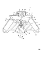
- FIG. 1 is a cross-sectional view showing the internal configuration of the centrifuge of the first embodiment.
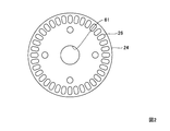
- FIG. 2 is a plan view of the disc
- FIG. 3 is a diagram showing the relationship between the disc and the leaf spring.
- a rotary shaft 3 having a vertical axis 9, a rotary head 2 attached to the top of the rotary shaft 3, a rotor 20 disposed on the top of the rotary head 2, and the top of the rotor 20 are illustrated.
- a cover 21, a knob 22, a knob shaft 25, a disc 24, a leaf spring 27, an elastic body 29, and the like are shown.
- the rotor lid mechanism of the present invention includes at least a lid 21, a knob 22, a knob shaft 25, a disk 24, a leaf spring 27, and an elastic body 29.
- a motor for rotating the rotary shaft 3 and a casing for covering the whole are components of the centrifuge 1.
- the upper side of the rotor 20 is a portion for inserting a sample, and includes a plurality of sample insertion portions 31.
- the lid 21 covers the surface on which the sample insertion portion 31 of the rotor 20 is present.
- the rotor 20 also includes a rotor hole 34 into which the rotary head 2 is inserted, a frame 32, a guide pin 33, and the like.
- the rotor hole 34 is a hole having a circular cross section with a diameter that gradually decreases to a predetermined depth and thereafter has a constant diameter.
- the frame 32 has a hole through which the knob shaft 25 passes.
- the rotary head 2 includes a rotor coupling portion 6 and a drive pin 7 at the top.
- the rotor coupling portion 6 has a cylindrical shape centered on the axis 9 of the rotating shaft.
- the rotary head 2 also has a cylindrical portion 4 having a constant diameter and a circular cross-section that fits in the rotor hole 34, and a circular truncated cone portion 5 having a circular cross-section that increases in diameter toward the bottom. Further, a screw portion 8 is formed in the portion of the axial center 9 of the cylindrical portion 4.
- the knob 22 is rotated when the lid 21 is attached or removed.
- the knob shaft 25 has a columnar shape fixed to the knob 22 so that the center of the knob 22 coincides with the center thereof, or a columnar shape formed integrally with the knob 22.
- the knob shaft 25 penetrates the lid 21 and has a screw portion 23 at the tip.
- the screw part 23 is screwed to the screw part 8 of the rotary head 2 by aligning the center of the knob shaft 25 with the axis 9 of the rotary shaft 3 and rotating the knob 22.
- the disc 24 is attached to the surface of the lid 21 that faces the knob 22.
- the disc 24 has a plurality of click holes 26 formed on the circumference whose center coincides with the axis 9 of the rotary shaft 3 and a shaft hole 61 through which the knob shaft passes.
- the knob shaft 25 may be fastened by a snap ring 30 or the like.
- the leaf spring 27 is attached to the surface of the knob 22 facing the disc 24 with screws 62. As for the leaf spring 27, when the knob 22 and the lid 21 are equal to or less than a predetermined distance, the distal end portion 28 is caught in the click hole 26.
- the elastic body 29 is disposed between the knob 22 and the lid 21 (or the disc 24), and presses the lid 21 against the rotor 20 according to the distance between the knob 22 and the lid 21.
- the predetermined interval is an interval that determines the length of the elastic body 29. When the predetermined interval or less, the natural length of the elastic body 29, the elastic coefficient, etc. are set so that the force for pressing the lid 21 is sufficient. Just decide.
- the guide pin 33 fixed to the frame 32 can move only between the drive pins 7, when the rotary head 2 rotates, power is transmitted from the drive pin 7 to the guide pins 33, and the rotor 20 rotates. Also, when the rotary head 2 stops, the drive pin 7 limits the movement range of the guide pin 33, so the rotor 20 stops together with the rotary head 2.
- the lid 21 is placed on the rotor 20 together with the knob 22 so that the screw portion 23 of the knob shaft 25 can be screwed to the screw portion 8 of the rotary head 2. Then, the knob 22 is turned to screw the screw portion 23 into the screw portion 8 of the rotary head 2. When the interval between the knob 22 and the lid 21 reaches a predetermined interval, the distal end portion 28 of the leaf spring 27 starts to be caught in the click hole 26 of the disc 24. When the knob 22 is further rotated, the distal end portion 28 of the leaf spring 27 is hooked on the click hole 26 and the leaf spring 27 is bent and detached from the click hole 26 is repeated. At this time, sound and vibration are generated by the leaf spring.
- the leaf spring 27 bends with the point 36 as a fulcrum.
- the sound and vibration generated by the leaf spring 27 are surely recognized by the user, for example, by using a disc or lid as a resonator.
- the lid is sufficiently tightened regardless of individual differences among users.
- the rotor lid mechanism of the present invention sound and vibration do not occur when the force required to turn the knob 22 becomes strong, but when the gap between the knob 22 and the lid 21 becomes a predetermined interval. To occur.
- the knob 22 may be turned without the knob shaft 25 being accurately inserted into the rotary head.
- the screw portion 8 of the knob shaft 25 is not normally inserted into the screw portion 8 of the rotary head 2, the screw portion 8 meshes with the screw portion 8 in an abnormal state, and the gap between the knob 22 and the lid 21.
- the mechanism of the present invention cannot be achieved by a mechanism that allows the user to recognize that it has been idled when it exceeds a predetermined force, such as a torque wrench or a lid of an automobile fuel filler, and has been tightened with a necessary force by sound or vibration. .
- a predetermined force such as a torque wrench or a lid of an automobile fuel filler
- the rotor lid mechanism of the present invention can recognize that the interval between the knob 22 and the lid 21 has become a predetermined interval, so that the knob is sufficiently tightened regardless of individual differences among users. Can be confirmed.
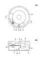
- FIG. 4 shows the configuration of the knob and the leaf spring of this modification.
- FIG. 4A is a view of the knob viewed from the lower side, and the knob shaft 25 is omitted.
- 4B is a cross-sectional view taken along the line CC of FIG. 4A.
- the leaf spring 50 has a curved portion and is attached to the surface of the knob 22 facing the disc 24 with a screw 63. As for the leaf spring 50, when the knob 22 and the lid 21 are less than a predetermined distance, the tip 53 is caught in the click hole 26.
- a reinforcing plate 51 is disposed below the leaf spring 50, and a space 52 is formed above the leaf spring 50.
- the leaf spring 50 bends in the direction opposite to the arrow 54.
- the fulcrum at this time is point 56. Since the distance between the point 56 and the tip portion 53 is longer than the distance between the point 55 and the tip portion 53, the stress applied to the leaf spring 50 is reduced.
- the fulcrum is different between when tightening and when loosening, the portion where the stress is concentrated varies depending on when tightening and when loosening. Therefore, the life of the leaf spring 50 is structurally longer than that of the leaf spring 27. Furthermore, since the leaf spring 50 has a curved portion, the bent portion can be dispersed. This is also a point that can extend the life.
- the user can confirm that the knob is sufficiently tightened by sound and vibration as in the first embodiment. Furthermore, since the life of the leaf spring can be extended, the reliability of the centrifuge can be maintained for a long time.
- the knob shaft 25 is screwed to the rotary head 2.
- the knob shaft 25 ′ is fastened to the rotor 20.
- the rotor 20 is securely fastened to the rotary head 2.
- FIG. 5 is a cross-sectional view showing the internal configuration of the centrifuge of this modification. Differences from FIG. 1 will be described.
- the frame 32 ' is pressed against the rotary head 2, and the rotor 20 is also fixed.
- the lid 21 is fixed to the rotor 20 by tightening the screw portion 23 ′ of the knob shaft 25 ′ to the screw portion 8 ′ formed on the rotor 20.
- Other configurations are the same as those of the first embodiment (FIG. 1).
Abstract
Description
まず、なぜ蓋やロータが離脱する課題が残っているのかを検討した。その結果、遠心分離機の蓋の締め付けを行う人たちの個人差が大きいことが要因であると思われる。詳細に説明すると、遠心分離機の蓋の締め付けは、エンドユーザが行うものである。そして、エンドユーザには、力の強い人と力の弱い人、遠心分離機の使用に慣れている人と慣れていない人、遠心分離機の危険性について熟知している人と知らない人など、いろいろな人がいる。したがって、蓋の締め付けが十分と感じる程度には個人差がある。また、不慣れな人の場合、つまみシャフトを正確に回転ヘッドに差し込んでいない状態で、つまみを回してしまうこともありえる。このような場合には正常でない状態でネジが噛み合ってしまい、強い力でつまみを回したとしても、蓋は十分に締め付けられていない。このような個人差によって、蓋の締め付けの強さが変化する。そこで、本発明では、蓋の締め付けが緩くなることを防ぐために、遠心分離機の蓋の締め付けの個人差をなくす。 Examination of the cause First of all, we examined why there are still problems with lids and rotors coming off. As a result, it seems that this is due to the large individual differences among the people who tighten the centrifuge lids. More specifically, the centrifuge lid is tightened by the end user. And for end users, strong and weak people, people who are used and unfamiliar with the use of centrifuges, people who are familiar with the dangers of centrifuges and those who do not know There are various people. Therefore, there are individual differences in the degree to which the lid is sufficiently tightened. In addition, in the case of an unfamiliar person, the knob may be turned without the knob shaft being accurately inserted into the rotary head. In such a case, the screws mesh with each other in an abnormal state, and the lid is not sufficiently tightened even if the knob is turned with a strong force. Due to such individual differences, the strength of the lid tightening changes. Therefore, in the present invention, in order to prevent the tightening of the lid from being loosened, individual differences in the tightening of the lid of the centrifuge are eliminated.
図1は、実施例1の遠心分離機の内部の構成を示す断面図である。図2は円板の平面図、図3は円板と板バネの関係を示す図である。図1には、軸心9が鉛直方向である回転シャフト3と、回転シャフト3の上部に取り付けられた回転ヘッド2と、回転ヘッド2の上部に配置されるロータ20と、ロータ20の上部を覆う蓋21、つまみ22、つまみシャフト25、円板24、板バネ27、弾性体29などが示されている。本発明のロータ用蓋部機構は、少なくとも蓋21、つまみ22、つまみシャフト25、円板24、板バネ27、弾性体29で構成される。なお、図示されていないが、回転シャフト3を回転させるためのモータ、全体を覆うための筺体なども、遠心分離機1の構成要素である。 Configuration FIG. 1 is a cross-sectional view showing the internal configuration of the centrifuge of the first embodiment. FIG. 2 is a plan view of the disc, and FIG. 3 is a diagram showing the relationship between the disc and the leaf spring. In FIG. 1, a
本変形例では、板バネの形状と板バネの止め方を変更し、板バネの長寿命化を図る。図4に、本変形例のつまみと板バネの構成を示す。図4Aは、つまみを下部側から見た図であって、つまみシャフト25は省略している。図4Bは、図4AのC-C線での断面図である。板バネ50は、湾曲した部分を有しており、つまみ22の円板24と対向する面にネジ63で取り付けられる。板バネ50は、つまみ22と蓋21とが所定間隔以下になるとクリック穴26に、先端部53が引っかかる。また、板バネ50の下側には補強板51が配置されており、板バネ50の上側には空間52が形成されている。 [Modification 1]
In this modification, the shape of the leaf spring and the method of stopping the leaf spring are changed to extend the life of the leaf spring. FIG. 4 shows the configuration of the knob and the leaf spring of this modification. FIG. 4A is a view of the knob viewed from the lower side, and the
実施例1と変形例1では、つまみシャフト25は回転ヘッド2にネジ止めされた。本変形例では、つまみシャフト25’をロータ20に締め付ける。また、ロータ20は回転ヘッド2に確実に締め付ける。 [Modification 2]
In the first embodiment and the first modification, the
3 回転シャフト 4 円柱部分
5 円錐台部分 6 ロータ結合部
7 駆動ピン 8、78 ネジ部分
9 軸心 20 ロータ
21 蓋 22 つまみ
23 ネジ部 24 円板
25 つまみシャフト 26 クリック穴
27 板バネ 28 先端部
29 弾性体 30 スナップリング
31 試料挿入部 32 フレーム
33 ガイドピン 34 ロータ穴
50 板バネ 51 補強板
52 空間 53 先端部
61 シャフト穴 62、63、79 ネジ DESCRIPTION OF
Claims (5)
- 回転シャフトと、前記回転シャフトの一端に固定された回転ヘッドと、試料を入れる試料挿入部を有し前記回転ヘッドに取り付けられるロータを備える遠心分離機の前記ロータの前記試料挿入部がある面を覆うためのロータ用蓋部機構であって、
前記ロータの前記試料挿入部がある面を覆う蓋と、
前記蓋の取り付け、取り外しのときに回転させるつまみと、
前記つまみの中心と中心が一致するように、前記つまみに固着された円柱状の形状もしくは前記つまみと一体的に形成された円柱状の形状であって、前記蓋を貫通しており、先端にネジ部を有するつまみシャフトと、
前記蓋の前記つまみと対向する面に取り付けられ、前記回転シャフトの軸心と中心が一致する円周上に形成された複数のクリック穴と、前記つまみシャフトを通過させるシャフト穴を有する円板と、
前記つまみの前記円板と対向する面に取り付けられ、前記つまみと前記蓋とが所定間隔以下になると前記クリック穴に引っかかる板バネと、
前記つまみと前記蓋との間に配置され、前記つまみと前記蓋との間の距離に応じて前記蓋を押さえる弾性体と
を備え、
前記つまみを、前記つまみと前記蓋とが前記所定間隔以下の状態で回転させると、前記板バネがクリック穴に引っかかること、前記板バネがたわんで当該クリック穴から外れることを繰り返す
ことを特徴とするロータ用蓋部機構。 A rotating shaft, a rotating head fixed to one end of the rotating shaft, and a surface having the sample inserting portion of the rotor of the centrifuge having a sample inserting portion for inserting a sample and a rotor attached to the rotating head. A rotor lid mechanism for covering,
A lid that covers the surface of the rotor where the sample insertion portion is located;
A knob that rotates when the lid is attached and removed;
A cylindrical shape fixed to the knob or a cylindrical shape formed integrally with the knob so that the center of the knob coincides with the center, and penetrates the lid, A knob shaft having a threaded portion;
A plurality of click holes attached to a surface of the lid facing the knob and formed on a circumference whose center coincides with the axis of the rotary shaft; and a disk having a shaft hole through which the knob shaft passes. ,
A leaf spring that is attached to a surface of the knob facing the disc, and that hooks into the click hole when the knob and the lid are less than a predetermined distance;
An elastic body that is disposed between the knob and the lid and holds the lid according to a distance between the knob and the lid;
When the knob is rotated in a state where the knob and the lid are less than or equal to the predetermined interval, the leaf spring is repeatedly hooked into the click hole, and the leaf spring is bent and detached from the click hole. The rotor lid mechanism. - 請求項1記載のロータ用蓋部機構であって、
前記板バネは、前記つまみを固定する方向に回転させるときと、前記つまみを開放する方向に回転させるときで、たわむときの支点が異なり、
前記つまみを固定する方向に回転させるときの支点の方が、前記クリック穴に引っかかる部分に近い
ことを特徴とするロータ用蓋部機構。 The rotor lid mechanism according to claim 1,
When the leaf spring is rotated in the direction to fix the knob and when it is rotated in the direction to open the knob, the fulcrum when bending is different,
A rotor lid mechanism, wherein a fulcrum when rotating the knob in a fixing direction is closer to a portion caught in the click hole. - 請求項1または2記載のロータ用蓋部機構であって、
前記板バネは、湾曲した部分を有している
ことを特徴とするロータ用蓋部機構。 The rotor lid mechanism according to claim 1 or 2,
The said leaf | plate spring has a curved part. The cover part mechanism for rotors characterized by the above-mentioned. - 請求項1から3のいずれかに記載のロータ用蓋部機構であって、
前記つまみシャフトのネジ部が、前記ロータにネジ止めされる
ことを特徴とするロータ用蓋部機構。 The rotor lid mechanism according to any one of claims 1 to 3,
The rotor lid portion mechanism, wherein a screw portion of the knob shaft is screwed to the rotor. - 請求項1から3のいずれかに記載のロータ用蓋部機構であって、
前記つまみシャフトのネジ部が、前記回転ヘッドにネジ止めされる
ことを特徴とするロータ用蓋部機構。 The rotor lid mechanism according to any one of claims 1 to 3,
The rotor lid mechanism, wherein a screw portion of the knob shaft is screwed to the rotary head.
Priority Applications (4)
| Application Number | Priority Date | Filing Date | Title |
|---|---|---|---|
| KR1020117020878A KR101275680B1 (en) | 2009-06-30 | 2010-04-08 | Lid-section mechanism for rotor |
| EP10793901.9A EP2450107B1 (en) | 2009-06-30 | 2010-04-08 | Lid-section mechanism for rotor |
| CN2010800174319A CN102405108B (en) | 2009-06-30 | 2010-04-08 | Lid-section mechanism for rotor |
| US13/256,428 US8414466B2 (en) | 2009-06-30 | 2010-04-08 | Centrifuge rotor cover |
Applications Claiming Priority (2)
| Application Number | Priority Date | Filing Date | Title |
|---|---|---|---|
| JP2009-155611 | 2009-06-30 | ||
| JP2009155611A JP5438396B2 (en) | 2009-06-30 | 2009-06-30 | Rotor lid mechanism |
Publications (1)
| Publication Number | Publication Date |
|---|---|
| WO2011001730A1 true WO2011001730A1 (en) | 2011-01-06 |
Family
ID=43410814
Family Applications (1)
| Application Number | Title | Priority Date | Filing Date |
|---|---|---|---|
| PCT/JP2010/056381 WO2011001730A1 (en) | 2009-06-30 | 2010-04-08 | Lid-section mechanism for rotor |
Country Status (6)
| Country | Link |
|---|---|
| US (1) | US8414466B2 (en) |
| EP (1) | EP2450107B1 (en) |
| JP (1) | JP5438396B2 (en) |
| KR (1) | KR101275680B1 (en) |
| CN (1) | CN102405108B (en) |
| WO (1) | WO2011001730A1 (en) |
Families Citing this family (6)
| Publication number | Priority date | Publication date | Assignee | Title |
|---|---|---|---|---|
| JP5438396B2 (en) * | 2009-06-30 | 2014-03-12 | 株式会社久保田製作所 | Rotor lid mechanism |
| JP6168448B2 (en) * | 2012-09-14 | 2017-07-26 | パナソニックIpマネジメント株式会社 | Screw fixing mechanism |
| JP1619045S (en) * | 2018-03-09 | 2018-11-26 | ||
| JP1634437S (en) * | 2018-04-30 | 2019-06-17 | ||
| KR102417012B1 (en) | 2020-06-15 | 2022-07-05 | (주)노바프로 | Fixed angle rotor |
| CN113522540B (en) * | 2021-09-13 | 2022-02-18 | 深圳市瑞沃德生命科技有限公司 | Rotor and centrifugal machine with same |
Citations (7)
| Publication number | Priority date | Publication date | Assignee | Title |
|---|---|---|---|---|
| JPS52114369U (en) * | 1976-02-25 | 1977-08-30 | ||
| JPH0721137U (en) * | 1993-09-27 | 1995-04-18 | 株式会社久保田製作所 | Angle rotor and tube holding plate for centrifuge |
| JP2002086017A (en) | 2000-09-20 | 2002-03-26 | Kubota Seisakusho:Kk | Attaching structure for rotor centrifuge |
| JP2005526604A (en) * | 2002-04-22 | 2005-09-08 | ケンドロ ラボラトリー プロダクツ, リミテッドパートナーシップ | Method and apparatus for attaching a cover |
| JP2006130485A (en) * | 2004-11-09 | 2006-05-25 | Hitachi Koki Co Ltd | Rotor for centrifugal machine, and centrifugal machine |
| WO2007134624A1 (en) * | 2006-05-23 | 2007-11-29 | Eppendorf Ag | Lid for closing a centrifuge rotor |
| JP2008307495A (en) * | 2007-06-18 | 2008-12-25 | Hitachi Koki Co Ltd | Rotor for centrifuge and centrifuge equipped therewith |
Family Cites Families (10)
| Publication number | Priority date | Publication date | Assignee | Title |
|---|---|---|---|---|
| US3819111A (en) * | 1973-04-09 | 1974-06-25 | Sorvall Inc Ivan | Centrifuge rotor cover |
| JPS52114369A (en) | 1976-03-22 | 1977-09-26 | Seiko Epson Corp | Dial of timepiece driven by solar battery |
| US4360151A (en) * | 1980-07-01 | 1982-11-23 | Beckman Instruments, Inc. | Aerosol resistant bowl rotor |
| US4753631A (en) * | 1986-11-03 | 1988-06-28 | E. I. Du Pont De Nemours And Company | Speed limiting arrangement for a centrifuge rotor having an axial mounting bolt |
| US5344380A (en) * | 1992-09-30 | 1994-09-06 | Beckman Instruments, Inc. | Release handle for centrifuge rotor and lid |
| JPH0721137A (en) | 1993-06-22 | 1995-01-24 | Hitachi Ltd | Device and processor for communication |
| FR2770154B1 (en) * | 1997-10-23 | 1999-11-26 | Jouan | CENTRIFUGE WITH REMOVABLE ROTOR AND WITH AXIAL LOCKING DEVICE OF THE ROTOR ON A DRIVE HEAD, AND ROTOR FOR SUCH A CENTRIFUGE |
| US6764438B2 (en) | 2002-04-22 | 2004-07-20 | Kendro Laboratory Products, Lp | Cover attachment apparatus |
| DE102005014218B4 (en) * | 2005-03-29 | 2008-03-06 | Thermo Electron Led Gmbh | Fastening device of a lid for a centrifuge rotor |
| JP5438396B2 (en) * | 2009-06-30 | 2014-03-12 | 株式会社久保田製作所 | Rotor lid mechanism |
-
2009
- 2009-06-30 JP JP2009155611A patent/JP5438396B2/en active Active
-
2010
- 2010-04-08 KR KR1020117020878A patent/KR101275680B1/en active IP Right Grant
- 2010-04-08 WO PCT/JP2010/056381 patent/WO2011001730A1/en active Application Filing
- 2010-04-08 EP EP10793901.9A patent/EP2450107B1/en active Active
- 2010-04-08 US US13/256,428 patent/US8414466B2/en active Active
- 2010-04-08 CN CN2010800174319A patent/CN102405108B/en active Active
Patent Citations (7)
| Publication number | Priority date | Publication date | Assignee | Title |
|---|---|---|---|---|
| JPS52114369U (en) * | 1976-02-25 | 1977-08-30 | ||
| JPH0721137U (en) * | 1993-09-27 | 1995-04-18 | 株式会社久保田製作所 | Angle rotor and tube holding plate for centrifuge |
| JP2002086017A (en) | 2000-09-20 | 2002-03-26 | Kubota Seisakusho:Kk | Attaching structure for rotor centrifuge |
| JP2005526604A (en) * | 2002-04-22 | 2005-09-08 | ケンドロ ラボラトリー プロダクツ, リミテッドパートナーシップ | Method and apparatus for attaching a cover |
| JP2006130485A (en) * | 2004-11-09 | 2006-05-25 | Hitachi Koki Co Ltd | Rotor for centrifugal machine, and centrifugal machine |
| WO2007134624A1 (en) * | 2006-05-23 | 2007-11-29 | Eppendorf Ag | Lid for closing a centrifuge rotor |
| JP2008307495A (en) * | 2007-06-18 | 2008-12-25 | Hitachi Koki Co Ltd | Rotor for centrifuge and centrifuge equipped therewith |
Non-Patent Citations (1)
| Title |
|---|
| See also references of EP2450107A4 * |
Also Published As
| Publication number | Publication date |
|---|---|
| JP5438396B2 (en) | 2014-03-12 |
| US8414466B2 (en) | 2013-04-09 |
| CN102405108A (en) | 2012-04-04 |
| KR20110114711A (en) | 2011-10-19 |
| EP2450107A1 (en) | 2012-05-09 |
| CN102405108B (en) | 2013-04-10 |
| KR101275680B1 (en) | 2013-06-17 |
| EP2450107B1 (en) | 2013-07-31 |
| US20120004089A1 (en) | 2012-01-05 |
| EP2450107A4 (en) | 2013-01-23 |
| JP2011011119A (en) | 2011-01-20 |
Similar Documents
| Publication | Publication Date | Title |
|---|---|---|
| WO2011001730A1 (en) | Lid-section mechanism for rotor | |
| US11111929B2 (en) | Blower fan having impeller and motor | |
| KR20120037510A (en) | Vibration-isolating fastening assembly | |
| JP5511962B2 (en) | Holding member for fixing the device | |
| JP5597477B2 (en) | Nut loosening prevention device | |
| JP2011251635A (en) | Tire valve unit | |
| EP2741282B1 (en) | Percussion attachment | |
| EP0824195A1 (en) | Sound attenuating motor end shield | |
| US10883514B2 (en) | Blower fan | |
| JP5860501B2 (en) | Power transmission device | |
| US7871219B2 (en) | Connection mechanism of plate member and shaft member | |
| JP5212907B2 (en) | centrifuge | |
| EP1850094A2 (en) | Rotation sensor | |
| JP2007107561A (en) | Power transmission device | |
| EP3786596B1 (en) | A vibration detection instrument assembly and method of assembling a vibration detection instrument assembly | |
| JP2009527662A (en) | Door or window handle fixing mechanism | |
| KR20190107028A (en) | Mixer with clamping sleeve assembly | |
| US20080010529A1 (en) | Shock prevention structure for motor | |
| JP2003144977A (en) | Centrifuge | |
| JPH0135248Y2 (en) | ||
| JP2009103158A (en) | Relaxing-stop mounting bolt and fixing unit using the same | |
| JP2007120643A (en) | Power transmission device | |
| JPS62159041A (en) | Fixed sensor structure | |
| JP3952251B2 (en) | Disc brake device and disc rotor of the device | |
| JP2009041945A (en) | Rotation detection sensor mounting structure |
Legal Events
| Date | Code | Title | Description |
|---|---|---|---|
| WWE | Wipo information: entry into national phase |
Ref document number: 201080017431.9 Country of ref document: CN |
|
| 121 | Ep: the epo has been informed by wipo that ep was designated in this application |
Ref document number: 10793901 Country of ref document: EP Kind code of ref document: A1 |
|
| ENP | Entry into the national phase |
Ref document number: 20117020878 Country of ref document: KR Kind code of ref document: A |
|
| WWE | Wipo information: entry into national phase |
Ref document number: 13256428 Country of ref document: US |
|
| WWE | Wipo information: entry into national phase |
Ref document number: 2010793901 Country of ref document: EP |
|
| NENP | Non-entry into the national phase |
Ref country code: DE |