WO2010143401A1 - Offset printing device - Google Patents
Offset printing device Download PDFInfo
- Publication number
- WO2010143401A1 WO2010143401A1 PCT/JP2010/003776 JP2010003776W WO2010143401A1 WO 2010143401 A1 WO2010143401 A1 WO 2010143401A1 JP 2010003776 W JP2010003776 W JP 2010003776W WO 2010143401 A1 WO2010143401 A1 WO 2010143401A1
- Authority
- WO
- WIPO (PCT)
- Prior art keywords
- guide rail
- printing
- plate
- gantry
- guide
- Prior art date
Links
Images


Classifications
-
- B—PERFORMING OPERATIONS; TRANSPORTING
- B41—PRINTING; LINING MACHINES; TYPEWRITERS; STAMPS
- B41F—PRINTING MACHINES OR PRESSES
- B41F3/00—Cylinder presses, i.e. presses essentially comprising at least one cylinder co-operating with at least one flat type-bed
- B41F3/46—Details
- B41F3/58—Driving, synchronising, or control gear
- B41F3/60—Driving, synchronising, or control gear for type-beds
-
- B—PERFORMING OPERATIONS; TRANSPORTING
- B41—PRINTING; LINING MACHINES; TYPEWRITERS; STAMPS
- B41F—PRINTING MACHINES OR PRESSES
- B41F3/00—Cylinder presses, i.e. presses essentially comprising at least one cylinder co-operating with at least one flat type-bed
- B41F3/18—Cylinder presses, i.e. presses essentially comprising at least one cylinder co-operating with at least one flat type-bed of special construction or for particular purposes
- B41F3/20—Cylinder presses, i.e. presses essentially comprising at least one cylinder co-operating with at least one flat type-bed of special construction or for particular purposes with fixed type-beds and travelling impression cylinders
-
- B—PERFORMING OPERATIONS; TRANSPORTING
- B41—PRINTING; LINING MACHINES; TYPEWRITERS; STAMPS
- B41F—PRINTING MACHINES OR PRESSES
- B41F3/00—Cylinder presses, i.e. presses essentially comprising at least one cylinder co-operating with at least one flat type-bed
- B41F3/18—Cylinder presses, i.e. presses essentially comprising at least one cylinder co-operating with at least one flat type-bed of special construction or for particular purposes
- B41F3/26—Cylinder presses, i.e. presses essentially comprising at least one cylinder co-operating with at least one flat type-bed of special construction or for particular purposes with type-beds and impression cylinders simultaneously movable relative to one another
-
- B—PERFORMING OPERATIONS; TRANSPORTING
- B41—PRINTING; LINING MACHINES; TYPEWRITERS; STAMPS
- B41F—PRINTING MACHINES OR PRESSES
- B41F3/00—Cylinder presses, i.e. presses essentially comprising at least one cylinder co-operating with at least one flat type-bed
- B41F3/18—Cylinder presses, i.e. presses essentially comprising at least one cylinder co-operating with at least one flat type-bed of special construction or for particular purposes
- B41F3/36—Cylinder presses, i.e. presses essentially comprising at least one cylinder co-operating with at least one flat type-bed of special construction or for particular purposes for intaglio or heliogravure printing
-
- B—PERFORMING OPERATIONS; TRANSPORTING
- B41—PRINTING; LINING MACHINES; TYPEWRITERS; STAMPS
- B41F—PRINTING MACHINES OR PRESSES
- B41F3/00—Cylinder presses, i.e. presses essentially comprising at least one cylinder co-operating with at least one flat type-bed
- B41F3/46—Details
- B41F3/51—Type-beds; Supports therefor
-
- B—PERFORMING OPERATIONS; TRANSPORTING
- B41—PRINTING; LINING MACHINES; TYPEWRITERS; STAMPS
- B41F—PRINTING MACHINES OR PRESSES
- B41F3/00—Cylinder presses, i.e. presses essentially comprising at least one cylinder co-operating with at least one flat type-bed
- B41F3/46—Details
- B41F3/54—Impression cylinders; Supports therefor
- B41F3/56—Devices for adjusting cylinders relative to type-beds and setting in adjusted position
-
- H—ELECTRICITY
- H05—ELECTRIC TECHNIQUES NOT OTHERWISE PROVIDED FOR
- H05K—PRINTED CIRCUITS; CASINGS OR CONSTRUCTIONAL DETAILS OF ELECTRIC APPARATUS; MANUFACTURE OF ASSEMBLAGES OF ELECTRICAL COMPONENTS
- H05K3/00—Apparatus or processes for manufacturing printed circuits
- H05K3/10—Apparatus or processes for manufacturing printed circuits in which conductive material is applied to the insulating support in such a manner as to form the desired conductive pattern
- H05K3/12—Apparatus or processes for manufacturing printed circuits in which conductive material is applied to the insulating support in such a manner as to form the desired conductive pattern using thick film techniques, e.g. printing techniques to apply the conductive material or similar techniques for applying conductive paste or ink patterns
Definitions
- the present invention relates to an offset printing apparatus used for printing a fine print pattern on a printing object with high printing accuracy, as in the case of forming an electrode pattern on a substrate by printing.
- One of the printing technologies is offset printing.
- the ink is once transferred (received) to a blanket roll that rolls from the inked intaglio, and then the ink is retransferred (printed) from the blanket roll to the printing target.
- the printing pattern of the said intaglio can be printed on the surface of printing object with sufficient reproducibility.
- the required accuracy differs slightly depending on the object.
- the overlay shift is suppressed to several ⁇ m. A very high position accuracy is required.
- a flat printing apparatus using a flat plate similar to the printing target is used as a plate.
- a printing apparatus shown in FIG. 4 has been proposed as one method for improving the printing accuracy by reducing the positional error between the blanket roll and the plate or the printing target when performing offset printing.
- a plate carriage (plate table) 2 that supports a platen table (not shown) on which a flat plate 1 is placed, and a glass substrate 3 to be printed (printed material) are placed.
- Sliders 5 and 6 are provided below the printing carriage (table to be printed) 4 that supports a printing surface plate (not shown).
- the sliders 5 and 6 have the same dimensions and are fixed to the lower portions of the plate carriage 2 and the printing carriage 4 in the same arrangement.
- the plate carriage 2 and the printing carriage 4 are provided on the same rail (guide rail) 7 so as to travel (reciprocate) via sliders 5 and 6, respectively.
- a blanket cylinder (blanket roll) 8 is provided so as to straddle the rail 7. According to such a configuration, even if the straightness of the rail 7 decreases directly below the blanket cylinder 8 and the postures of the printing carriage 2 and the printing carriage 4 are inclined at the position, the two carriages 2 and 4 have the same inclination. It becomes.
- the posture error between the plate 1 and the glass substrate 3 is suppressed, and the transfer (resin transfer) between the plate 1 and the blanket cylinder 8 is the same as the retransfer (pattern transfer) from the blanket cylinder 8 to the glass substrate 3. Since printing is performed at the position, the printing accuracy can be improved (see, for example, Patent Document 3).
- Patent Document 4 discloses a resin-coated substrate manufacturing apparatus shown in FIGS. 5 and 6.
- a pair of left and right guide rails 10 extending in the front-rear direction are installed on both sides of the fixed frame 9, and a pair of left and right sliders 11 are slidably attached to each guide rail 10.
- a pair of left and right movable frames 12 that rotatably hold the left and right rotation shafts of the transfer cylinder 13 are mounted on the pair of sliders 11, and the left and right movable frames are moved along with the movement of the sliders 11 along the guide rails 10.
- the transfer cylinder 13 can be moved relative to the fixed frame 9 in the front-rear direction together with 12.
- a letterpress reverse printing is performed on a substrate (not shown) as a printing target held on the fixed frame 9 via the transfer cylinder 13 to manufacture a resin coated substrate.
- a pair of horizontal surfaces 14 and a pair of vertical surfaces 15 for supporting the guide rail 10 in the vertical direction and the horizontal direction are provided on both sides of the fixed frame 9 by polishing so as to increase linearity, respectively.
- a pair of left and right guide rails 10 are provided on a horizontal plane 14 and a vertical plane 15 provided on the left and right sides of the fixed frame 9.
- Japanese Patent No. 2797567 Japanese Patent No. 3904433 JP 2008-129362 A Japanese Patent No. 4108012
- the present invention has been made in view of the above-described problems, and can obtain highly accurate position reproducibility when performing transfer from a plate to a blanket roll and retransfer from the blanket roll to a printing target.
- An object of the present invention is to provide an offset printing apparatus capable of achieving very high positional accuracy when it is required to suppress the positional deviation of a fine printed pattern such as electrode pattern formation to several ⁇ m.
- An offset printing apparatus includes a gantry, a guide rail provided on the gantry, a plurality of guide blocks provided on the guide rail, and a part of the plurality of guide blocks.
- the blanket roll is sequentially brought into contact with the printing target held on the printing target table from above, and the transfer from the plate to the blanket roll and the re-transfer from the blanket roll to the printing target are performed.
- An offset printing apparatus includes a gantry, a guide rail provided on the gantry, a plurality of guide blocks provided on the guide rail, and a part of the plurality of guide blocks.
- a plate table that travels through a guide block, a printing target table that travels through some other guide blocks of the plurality of guide blocks, and a blanket roll provided on the gantry.
- the blanket roll is sequentially brought into contact with the printing plate held on the table and the printing target held on the printing target table from above to transfer the plate to the blanket roll, and from the blanket roll to the printing target.
- a positioning step consisting of a vertical surface formed so as to have high linearity and a horizontal surface is provided, and one side surface and a bottom surface of the guide rail are pressed against and fixed to the vertical surface and the horizontal surface of the step portion.
- a step portion comprising a vertical surface formed so as to be highly linear by machining and a horizontal surface is provided, One side surface and an upper surface of the guide block are pressed against and fixed to the vertical surface and the horizontal surface of the stepped portion, respectively.
- the guide rail installation locations on the top surface of the gantry are two locations spaced at a predetermined interval in the width direction, and the step difference is provided at each of the installation locations of the guide rail.
- the parts may be provided so as to be both outward in the width direction or inward in the width direction.
- a stepped portion formed of a vertical surface and a horizontal surface formed so as to have high linearity by machining is provided at the central portion in the width direction of the frame, and the guide rail on the upper surface of the frame.
- a step portion consisting of a vertical surface and a horizontal surface formed so as to increase linearity by machining is provided. You may attach in the state which pressed the one side and upper surface of the needle
- a plate table and a printing target table that travel via individual guide blocks are provided on a guide rail provided on a gantry, a plate held on the plate table, and a printing target
- Steps for positioning are provided at the left and right guide rail installation locations on the upper surface of the gantry, each of which includes a vertical surface formed so as to have high linearity by machining and a horizontal surface that is aligned horizontally.
- the plate on the table and the printing target on the printing target table are in contact with the blanket roll in a state where straightness is enhanced. Therefore, the reproducibility of the position when the plate on the plate table contacts the blanket roll and the position when the printing target on the printing target table contacts the blanket roll can be improved. Therefore, it is possible to print the printing pattern of the plate on the printing object through the blanket roll with high positional accuracy and high reproducibility. Therefore, it is possible to achieve very high positional accuracy when it is required to suppress the positional deviation of a fine printed pattern such as electrode pattern formation to several ⁇ m.
- a stepped portion made up of a vertical surface and a horizontal surface formed so as to have high linearity by machining is provided at a position arranged above the guide rail in the bottom surface portion of the plate table and the printing target table.
- One side and the top of the guide block corresponding to the guide rail are pressed and fixed to the vertical and horizontal surfaces of the step, respectively, and fixed along the guide rail fixed along the highly linear step.
- the plate on the plate table that runs integrally with the guide block and the printing target on the printing target table may be in contact with the blanket roll in a state where straightness is enhanced.
- the posture of the plate table and the printing target table with respect to the blanket roll can be easily set to a desired posture, and the printing plate on the plate table and the printing target on the printing target table are arranged facing the blanket roll. It becomes possible to contact with.
- the guide rail installation locations on the top surface of the gantry are two locations with a predetermined interval in the width direction, and the step portions consisting of a vertical surface and a horizontal surface are both outside the width direction at the guide rail installation locations. You may provide so that it may become direction or width direction inward. With this configuration, it is possible to increase the rigidity against the external force in the lateral direction of the plate table or the printing target table that travels along the guide rail that is attached to each guide rail along the stepped portion. Therefore, even when a lateral external force is applied to the plate table or the printing target table, it is possible to prevent deterioration in printing accuracy.
- a stepped portion made of a vertical surface and a horizontal surface formed so as to have high linearity by machining at the center in the width direction of the gantry is parallel to the stepped portion provided at the guide rail installation location on the top surface of the gantry.
- a step part consisting of a vertical surface and a horizontal surface formed so as to have high linearity by machining was provided, and one side surface and the upper surface of the linear motor movable element were pressed against the vertical surface and the horizontal surface of the step part.
- a step portion comprising a vertical surface and a horizontal surface formed so as to have high linearity by machining, and a step portion provided at a guide rail installation location on the upper surface of the gantry, It may be provided in parallel and attached by pressing one side surface and the bottom surface of the linear scale against the vertical surface and the horizontal surface of the stepped portion provided at the required location on the upper surface portion of the gantry.
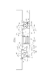
- FIG. 1 is a schematic side view showing an offset printing apparatus according to an embodiment of the present invention.
- FIG. 2 is a view of the offset printing apparatus of FIG.
- FIG. 3 is an enlarged front view showing a main part of the offset printing apparatus of FIG.
- FIG. 4 is a schematic plan view showing a conventional offset printing apparatus.
- FIG. 5 is a schematic front view showing a conventional resin-coated substrate manufacturing apparatus.
- FIG. 6 is an enlarged front view showing the guide rail installation structure on one side of the fixed frame in the resin-coated substrate manufacturing apparatus of FIG.
- FIG. 1 to 3 show an offset printing apparatus according to an embodiment of the present invention.
- the offset printing apparatus is provided on a horizontal base 19, a pair of left and right guide rails 20a and 20b extending in one direction (X-axis direction), and above each guide rail 20a and 20b.
- a plate table 23 that can hold a flat plate 22, a print target table 25 that is provided above the guide rails 20 a and 20 b and can hold a flat print target 24 such as a substrate, and each guide rail.
- the plate table 23 and the printing target table 25 are slidably attached to the guide rails 20a and 20b via the guide blocks 21a and 21b, respectively.
- a stator 27 of the linear motor 26 is installed on the gantry 19 along the X-axis direction.
- a mover 28 of a linear motor 26 is installed on each of the plate table 23 and the printing target table 25.
- the plate table 23 and the printing target table 25 can reciprocate (run) independently along the guide rails 20 a and 20 b by driving the linear motor 26.
- the transfer mechanism 29 is provided with the blanket roll 30, the elevation drive mechanism 31 such as a ball screw mechanism for raising and lowering the blanket roll 30, and the rotation drive motor 32 for rotationally driving the blanket roll 30.
- the guide rails 20 a, 20 b are located at a midway position different from the transfer mechanism 29 within the range in which the plate table 23 can travel, for example, the guide rails 20 a
- An inking device 33 for inking the plate 22 held on the plate table 23 is provided at a position separated by a predetermined distance toward one end side in the longitudinal direction of 20b.
- Base members 34 a and 34 b for fixing the guide rails 20 a and 20 b are fixed to the upper surface of the gantry 19 at two positions in the left-right width direction, which are the installation positions of the left and right guide rails 20 a and 20 b.
- the base members 34a and 34b extend in the X-axis direction.
- the horizontal surfaces 37 of the base members 34a and 34b are parallel to each other and at the same height level.
- the left and right guide rails 20a and 20b are arranged on the base members 34a and 34b.
- a plurality of fixing bolts 38 as horizontal plane pressing means, a wedge-shaped guide presser 39 as vertical surface pressing means, and its fixing bolt 40 are provided at a plurality of positions with a predetermined interval in the longitudinal direction of each guide rail 20a, 20b.
- it is fixed to the corresponding base members 34a and 34b, respectively.
- each wedge-shaped guide retainer 39 causes the base members 34a and 34b to have the one side surface and the bottom surface serving as the reference surfaces of the guide rails 20a and 20b at the predetermined intervals in the longitudinal direction of the guide rails 20a and 20b. It can be accurately fixed to the vertical surface 36 and the horizontal surface 37 of each step 35 provided. Further, the linearity of each guide rail 20a, 20b in the X-axis direction can be ensured according to the accuracy of machining when the step portions 35 are provided on the base members 34a, 34b. Furthermore, by fixing each wedge-shaped guide holding member 39, the lateral rigidity of each guide rail 20a, 20b can be increased.
- a stepped portion (positioning shoulder) 41 composed of a vertical surface 42 and a horizontal surface 43 is ground so that the linearity along the X-axis direction of the vertical surface 42 is increased. It is provided by machining.
- the step portion 41 is provided on one of the left and right guide rails 20a and 20b, on one of the left and right guide blocks 20a and 21b. It is provided at the mounting location of the guide block arranged above. Further, on the bottom surface of the plate table 23 and the printing target table 25, the mounting position of the other guide block disposed on the right guide rail 20b in FIG.
- a level horizontal surface 44 is provided by machining such as grinding.
- the plate table 23 and the printing target table 25 are slidably attached to the corresponding guide rails 20a at the mounting position of one guide block provided with the step portion 41 on the bottom surface of the plate table 23 and the printing target table 25.
- the guide block 21a is arranged.
- one side surface and the upper surface, which are the reference surfaces of the guide block 21a are pressed against the vertical surface 42 and the horizontal surface 43 of the step portion 41 provided on the bottom surfaces of the tables 23 and 25, respectively.
- the guide block 21a is fixed to the bottom surfaces of the corresponding tables 23 and 25 by a plurality of fixing bolts 45 as horizontal surface pressing means, a wedge-shaped guide presser 46 as vertical surface pressing means and its fixing bolt 47, respectively. To do.
- each wedge-shaped guide presser 46 accurately aligns one side surface and the upper surface serving as the reference surface of the guide block 21a with the vertical surface 42 and the horizontal surface 43 of each stepped portion 41 provided on the bottom surfaces of the tables 23 and 25, respectively. Can be fixed to. Further, a straight line in the X-axis direction corresponding to the accuracy of machining when the stepped portion 41 is provided on the bottom surface of the plate table 23 and the printing target table 25 with the guide block 21a to be attached to the left guide rail 20a in FIG. It can be installed in a state where the property is secured. Furthermore, by fixing with the wedge-shaped guide holding 46, the lateral rigidity of the guide block 21a can be increased.
- a guide block 21b for slidably mounting the plate table 23 and the printing target table 25 on the other guide rail 20b is mounted on the horizontal plane 44 provided at the other guide block mounting portion on the bottom surface of the printing table 23 and the printing target table 25. Is placed.
- the guide block 21b is positioned on the guide rail 20a in which the linearity in the X-axis direction is secured on the gantry 19 with the guide block 21a positioned by the step portion 41 to ensure the linearity in the X-axis direction.
- the guide block 21b is fixed to the bottom surfaces of the corresponding tables 23 and 25 by the fixing bolt 45 in the same manner as the fixing bolt 45 of one guide rail 20a.
- the guide rails 20a and 20b are installed on the gantry 19 in a state in which linearity in the X-axis direction is ensured, and the left and right guide blocks 21a and 21b corresponding to the guide rails 20a and 20b.
- One of the guide blocks 21a is attached to the plate table 23 and the printing target table 25 in a state where the linearity in the X-axis direction is ensured along the guide rails 20a and 20b. Therefore, when the plate table 23 and the printing target table 25 are moved, the machining accuracy of the step portions 35 provided on the base members 34a and 34b on the gantry 19 and the step portions 41 provided on the bottom surfaces of the tables 23 and 25 is improved.
- the straightness in the X-axis direction according to the can be ensured.
- one of the base members 34 a and 34 b mounted on the gantry 19, for example, the left base member 34 a in FIG. 3, has a wide width that reaches the center in the width direction of the gantry 19.
- a stepped portion comprising a vertical surface 49 parallel to the vertical surface 36 of the stepped portion 35 for mounting each guide rail 20a, 20b and a horizontal surface 50 at a position corresponding to the widthwise central portion of the gantry 19.
- (Positioning shoulder) 48 is provided by machining such as grinding so that the linearity along the X-axis direction of the vertical surface 49 is increased.
- a block-like attachment member 52 having a required vertical dimension is attached to an intermediate portion in the left-right width direction on the bottom surface of the plate table 23 and the printing target table 25.
- a stepped portion positioning portion for positioning
- the linear motor 26 for moving the plate table 23 and the printing target table 25 along the guide rails 20a and 20b is also provided with the stepped portion 48 for positioning the stator 27 provided on the base member 34a, and the attachment.
- the straightness in the X-axis direction according to the machining accuracy of the stepped portion 53 for positioning the mover 28 provided on the member 52 can be ensured.
- a vertical surface 57 parallel to 36 and a stepped portion (positioning shoulder) 56 composed of a horizontal surface 58 are provided by machining such as grinding so that the linearity along the X-axis direction of the vertical surface 57 is increased.
- a linear scale 59 is installed with reference to the vertical surface 57 and the horizontal surface 58 of the stepped portion 56. Thereby, in the linear scale 59, the linearity of the X-axis direction according to the machining precision of the step part 56 is ensured. Therefore, the linear scale 59 can detect the position along the X-axis direction of the plate table 23 and the printing target table 25 moving along the guide rails 20a and 20b with high accuracy.
- the left and right guide rails 20a and 20b on the mount 19 are located on the inner side of the left and right widths of the plate 22 and the print target 24 held on the plate table 23 and the print target table 25 as shown in FIG. Arrangement is preferred.
- the blanket roll 30 is brought into contact with the plate 22 held on the plate table 23 or the print target 24 held on the print target table 25 from above in the transfer mechanism 29 as described later.
- the load that the printing plate 22 and the printing object 24 receive from the blanket roll 30 when the pressure is applied It can be transmitted to the guide rails 20a and 20b located in the position.
- the joints 60 of the respective guide rails 20 a and 20 b are positioned at the place where the transfer mechanism 29 is installed. Further, the joints 60 of the left and right guide rails 20a and 20b are arranged so as to be shifted from each other by a predetermined dimension in the X-axis direction. Thereby, it is possible to suppress the running disturbance of the tables 23 and 25 caused by the plate table 23 and the printing target table 25 passing through the joints 60 of the left and right guide rails 20a and 20b at the same time. Further, when passing through the transfer mechanism 29, it is possible to prevent the running of the tables 23 and 25 from being disturbed.
- the plate 22 is held on the plate table 23 and the print target 24 is held on the print target table 25.
- the plate table 23 holding the plate 22 is moved to the inking device 33 by the linear motor 26 to perform inking.
- the plate table 23 holding the inked plate 22 and the print target table 25 holding the print target 24 are moved to a position upstream of the transfer mechanism 29 in the table running direction during transfer. Wait.
- the blanket roll 30 rotated by the circumferential movement amount synchronized with the movement amount of the plate 22 on the plate table 23 is changed to the plate table.
- the ink is transferred from the plate 22 to the blanket roll 30 by pressing the plate 22 on the plate 23 from above with a predetermined contact pressure.
- the plate table 23 is guided in the moving direction in a state where straightness is ensured by the guide rails 20a and 20b in which linearity in the X-axis direction is ensured and lateral rigidity is increased. Further, the plate table 23 is driven by a linear motor 26 that ensures straightness in the X-axis direction.
- the movement amount of the plate table 23 is detected by a linear scale 59 that ensures linearity in the X-axis direction. Therefore, the position control of the plate 22 on the plate table 23 can be performed with high accuracy, and the printing pattern of the plate 22 is transferred to the surface of the blanket roll 30 with high accuracy reproducibility.
- the blanket roll 30 rotated by the circumferential movement amount synchronized with the movement amount of the printing target 24 on the printing target table 25 is moved. Then, the printing object 24 on the printing object table 25 is pressed from above with a predetermined contact pressure, and the ink is retransferred from the blanket roll 30 to the printing object 24. At this time, like the plate table 23, the printing target table 25 moves in a state in which straightness is ensured by the guide rails 20a and 20b in which linearity in the X-axis direction is ensured and lateral rigidity is increased. Direction is guided.
- the printing target table 25 is driven by a linear motor 26 that ensures straightness in the X-axis direction. Furthermore, the movement amount of the print target table 25 is detected by a linear scale 59 that ensures linearity in the X-axis direction. Therefore, the position of the print target 24 on the print target table 25 can be controlled with high accuracy, and the print pattern transferred from the plate 22 onto the surface of the blanket roll 30 can be reproduced with high accuracy reproducibility. Transferred to the surface.
- the plate table 23 holding the plate 22 and the print target table 25 holding the print target 24 are placed under the same blanket roll 30 of the transfer mechanism 29. It can guide by guide rail 20a, 20b.
- the guide rails 20a and 20b ensure linearity in the X-axis direction according to the machining accuracy when the corresponding stepped portions 35 are provided. Therefore, the straightness of the plate table 23 holding the plate 22 and the print target table 25 holding the print target 24 can be ensured below the blanket roll 30 of the transfer mechanism unit 29, and the printing pattern of the plate 22 can be secured.
- the guide rails 20a and 20b are fixed along the vertical surfaces 36 of the step portions 35 facing outward in the width direction provided on the upper surfaces of the base members 34a and 34b fixed on the gantry 19. Furthermore, a wedge-shaped guide presser 39 is used as a fixing means for the guide rails 20a and 20b. Accordingly, the rigidity of the guide rails 20a and 20b against the lateral external force can be increased. Therefore, even when a lateral external force is applied to the guide rails 20a and 20b, it is possible to prevent deterioration in printing accuracy.
- this invention is not limited only to the said embodiment.
- the stepped portion 35 having the vertical surface 36 and the horizontal surface 37 for positioning the mounting position of each guide rail 20a, 20b on the upper surface portion of the mount 19 on the base members 34a, 34b provided on the mount 19.
- the stepped portion 35 may be provided directly on the top surface of the gantry 19.
- step-difference part 35 which consists of the vertical surface 36 and the horizontal surface 37 for pressing the side surface used as the reference surface of each guide rail 20a, 20b and the bottom face to each base member 34a, 34b is changed to the width direction.
- each step 35 may be inward in the width direction.
- the rigidity of the guide rails 20a and 20b against the external force in the lateral direction can be increased, and even if the external force in the lateral direction acts on the guide rails 20a and 20b, the printing accuracy is deteriorated. Can be prevented.
- vertical surface pressing means for pressing against the vertical surface 42 of the stepped portion 41 provided on the guide rail 20a, 20b or the guide block 21a it is pressed from the opposite side of the vertical surfaces 36, 42 of the stepped portions 35, 41.
- the transfer mechanism 29 can bring the blanket roll 30 into contact with the plate 22 held on the plate table 23 traveling along the guide rails 20a and 20b and the printing target 24 held on the printing target table 25 from above. If possible, any type of transfer mechanism 29 may be used.
- the inking device 33 may use any type of inking device 33 as long as appropriate inking can be performed on the plate 22 held on the plate table 23.
- the offset printing apparatus of the present invention may be applied when printing is performed on the printing object 24 other than the substrate.
- the offset printing apparatus of the present invention it is possible to improve the reproducibility of the position when the plate on the plate table contacts the blanket roll and the position when the printing object on the printing target table contacts the blanket roll. Therefore, the printing pattern of the plate can be printed on the printing target via the blanket roll with high positional accuracy and high reproducibility. Therefore, it is possible to achieve very high positional accuracy when it is required to suppress the positional deviation of a fine printed pattern such as electrode pattern formation to several ⁇ m.
Abstract
Description
本願は、2009年6月9日に、日本に出願された特願2009-138698号に基づき優先権を主張し、その内容をここに援用する。 The present invention relates to an offset printing apparatus used for printing a fine print pattern on a printing object with high printing accuracy, as in the case of forming an electrode pattern on a substrate by printing.
This application claims priority based on Japanese Patent Application No. 2009-138698 filed in Japan on June 9, 2009, the contents of which are incorporated herein by reference.
液晶ディスプレイ等の電極パターンを基板に形成する場合は、10μm程度の微細な電極幅が要求されることがある。更に、基板上に複数の電極パターンを重ね合わせて形成する場合は、版を代えて電極パターンの重ね刷りを行う。この場合、印刷位置がずれると電極パターンが崩れてしまうことから、対象によって要求精度は多少異なるが、電極幅が10μm程度であるような微細な電極パターンでは、重ね合わせずれを数μmに抑えるような非常に高い位置精度が必要とされる。 In recent years, as a method for forming electrode patterns (conductive patterns) on substrates, such as liquid crystal displays, printing techniques using conductive paste as printing ink instead of fine processing such as etching of metal deposition films, such as intaglio offset There has been proposed a method of printing and forming an electrode pattern on a substrate to be printed using a printing technique (see, for example,
When an electrode pattern such as a liquid crystal display is formed on a substrate, a fine electrode width of about 10 μm may be required. Further, when a plurality of electrode patterns are formed on the substrate in an overlapping manner, the electrode patterns are overprinted instead of the plate. In this case, since the electrode pattern collapses when the printing position is shifted, the required accuracy differs slightly depending on the object. However, in a fine electrode pattern having an electrode width of about 10 μm, the overlay shift is suppressed to several μm. A very high position accuracy is required.
更に、オフセット印刷を行う際にブランケットロールと版や印刷対象との位置誤差を小さくして印刷精度の向上を図るための手法の1つとして、図4に示される印刷装置が提案されている。この印刷装置では、平らな版1が載置される版定盤(図示せず)を支持する版台車(版テーブル)2と、印刷対象(被印刷物)となるガラス基板3が載置される印刷定盤(図示せず)を支持する印刷台車(印刷対象テーブル)4の下側に、スライダ5と6が設けられる。スライダ5と6は、それぞれ、同一寸法であり、同一配置で版台車2および印刷台車4の下部に固着される。版台車2と印刷台車4は、同一のレール(ガイドレール)7に、それぞれスライダ5と6を介して走行(往復動)するように設けられる。更に、レール7を跨ぐようにブランケット胴(ブランケットロール)8が設けられる。
かかる構成によれば、ブランケット胴8の直下でレール7の真直度が低下して、当該位置で版台車2及び印刷台車4の姿勢が傾いたとしても、双方の台車2と4が同一の傾きとなる。したがって、版1とガラス基板3との姿勢誤差が抑制され、版1とブランケット胴8との間の転写(樹脂転移)と、ブランケット胴8からガラス基板3への再転写(絵柄転写)が同一位置で行われるため、印刷精度を高めることができる(たとえば、特許文献3参照)。 Incidentally, as an offset printing apparatus for performing offset printing on a printing target with high printing accuracy, a flat printing apparatus using a flat plate similar to the printing target is used as a plate.
Furthermore, a printing apparatus shown in FIG. 4 has been proposed as one method for improving the printing accuracy by reducing the positional error between the blanket roll and the plate or the printing target when performing offset printing. In this printing apparatus, a plate carriage (plate table) 2 that supports a platen table (not shown) on which a
According to such a configuration, even if the straightness of the
更に、特許文献4に示された装置では、各ガイドレール10についての直線性、平行性の乱れを減少させることができる。しかしながら、各ガイドレール10に沿ってスライドする各スライダ11に取り付けた左右の可動フレーム12同士は、回転する転写胴13を介して連結されている。したがって、左右の可動フレーム12同士の前後方向の位置ずれがわずかにでも生じると、固定フレーム9上に固定される図示しない凸版や印刷対象としての基板に対して、転写胴13を正対させることができなくなってしまう。そのために、従来要求されていた印刷精度は満足させることができるとしても、電極パターン形成等の微細な印刷パターンの位置ずれを数μmに抑えることが要求される場合における非常に高い位置精度を達成することは難しい。 Further, in the apparatus for performing letterpress reverse printing described in
Furthermore, in the apparatus shown in
(1)本発明のオフセット印刷装置では、架台上に設けたガイドレール上に、個別のガイドブロックを介して走行する版テーブルと印刷対象テーブルを備え、版テーブルに保持させた版と、印刷対象テーブルに保持させた印刷対象に、ブランケットロールを上方より順次接触させることで、版からブランケットロールへの転写と、ブランケットロールから印刷対象への再転写を行う。架台の上面部における左右のガイドレール設置個所に、機械加工により直線性が高くなるよう形成した垂直面と、互いに水平に揃う水平面とからなる位置決め用の段差部を設ける。この段差部の垂直面と水平面に、ガイドレールの基準面となる一側面と底面をそれぞれ押し当てて固定し、直線性の高い段差部に沿わせて固定したガイドレールに沿わせて走行させる版テーブル上の版及び印刷対象テーブル上の印刷対象が、真直性が高められた状態でブランケットロールと接する。したがって、版テーブル上の版がブランケットロールに接触するときの位置と、印刷対象テーブル上の印刷対象がブランケットロールに接触するときの位置の再現性を高めることができる。よって、版の印刷パターンをブランケットロールを介して印刷対象に高い位置精度、高い再現性で印刷することができる。よって、電極パターン形成等の微細な印刷パターンの位置ずれを数μmに抑えることが要求される場合における非常に高い位置精度を達成することができる。 According to the offset printing apparatus of the present invention, the following excellent effects are exhibited.
(1) In the offset printing apparatus according to the present invention, a plate table and a printing target table that travel via individual guide blocks are provided on a guide rail provided on a gantry, a plate held on the plate table, and a printing target By sequentially bringing the blanket roll into contact with the printing object held on the table from above, transfer from the plate to the blanket roll and retransfer from the blanket roll to the printing object are performed. Steps for positioning are provided at the left and right guide rail installation locations on the upper surface of the gantry, each of which includes a vertical surface formed so as to have high linearity by machining and a horizontal surface that is aligned horizontally. A plate that runs along a guide rail that is fixed along a stepped portion with high linearity. The plate on the table and the printing target on the printing target table are in contact with the blanket roll in a state where straightness is enhanced. Therefore, the reproducibility of the position when the plate on the plate table contacts the blanket roll and the position when the printing target on the printing target table contacts the blanket roll can be improved. Therefore, it is possible to print the printing pattern of the plate on the printing object through the blanket roll with high positional accuracy and high reproducibility. Therefore, it is possible to achieve very high positional accuracy when it is required to suppress the positional deviation of a fine printed pattern such as electrode pattern formation to several μm.
図1乃至図3は本発明の一実施形態のオフセット印刷装置を示す。
先ず、本発明の一実施形態のオフセット印刷装置の全体構成について概説する。オフセット印刷装置は、水平な架台19と、水平な架台19の上側に設けられ、一方向(X軸方向)に延びる左右一対のガイドレール20a,20bと、各ガイドレール20a,20bの上側に設けられ、平板状の版22を保持可能な版テーブル23と、各ガイドレール20a,20bの上側に設けられ、基板等の平板状の印刷対象24を保持可能な印刷対象テーブル25と、各ガイドレール20a,20b上に設けられる左右2つずつ計4つのガイドブロック21a,21bと、を備える。版テーブル23および印刷対象テーブル25は、ガイドレール20a,20bに、ガイドブロック21a,21bを介してそれぞれスライド可能に取り付けられる。
更に、架台19上には、リニアモータ26の固定子27がX軸方向に沿って設置される。版テーブル23と印刷対象テーブル25には、リニアモータ26の可動子28がそれぞれ設置される。版テーブル23及び印刷対象テーブル25は、リニアモータ26の駆動により各ガイドレール20a,20bに沿って独立して往復動(走行)できる。 Hereinafter, embodiments for carrying out the present invention will be described with reference to the drawings.
1 to 3 show an offset printing apparatus according to an embodiment of the present invention.
First, the overall configuration of an offset printing apparatus according to an embodiment of the present invention will be outlined. The offset printing apparatus is provided on a
Further, a
左右の各ガイドレール20a,20bの設置個所となる左右幅方向の2個所において、各ガイドレール20a,20bをそれぞれ固定するためのベース部材34a,34bが、架台19の上面に固定される。ベース部材34a,34bは、X軸方向に延びる。
架台19上に固定した各ベース部材34a,34bの上面部には、垂直面36と水平面37からなる幅方向外向きの段差部(位置決め用の肩)35が、各垂直面36のX軸方向に沿う直線性が高くなるよう研削加工等の機械加工により設けられる。ベース部材34a,34bの垂直面36は、互いに平行である。ベース部材34a,34bの水平面37は、互いに平行かつ同一の高さレベルである。 Next, the main part of the offset printing apparatus of the present invention will be described in detail with reference to FIG.
On the upper surface of each
一方、版テーブル23及び印刷対象テーブル25の底面における左右幅方向の中間部には、所要の上下寸法を有するブロック状の取付部材52が取り付けられる。取付部材52の下端部には、各テーブル23,25の底面の一方のガイドブロック取付個所に設けた段差部41の垂直面42に平行な垂直面54と、水平面55からなる段差部(位置決め用の肩)53が、段差部53の垂直面54のX軸方向に沿う直線性が高くなるよう研削加工等の機械加工により設けられる。段差部53の垂直面54と水平面55にリニアモータ26の可動子28の基準面となる片側の側面と上面を押し当てた状態で、可動子28を取付部材52に、図示しない固定手段を介して固定する。これにより、版テーブル23及び印刷対象テーブル25を各ガイドレール20a,20bに沿って移動させるためのリニアモータ26にも、ベース部材34aに設けた固定子27位置決め用の段差部48、及び、取付部材52に設けた可動子28位置決め用の段差部53の機械加工の精度に応じたX軸方向の真直性を担保することができる。 Further, one of the
On the other hand, a block-
次に、インキングした版22を保持した版テーブル23と、印刷対象24を保持した印刷対象テーブル25を、転写機構部29よりも転写時におけるテーブル走行方向の上流側となる位置に移動させて待機させる。 When the offset printing apparatus of the present invention having the above configuration is used, the
Next, the plate table 23 holding the inked
よって、電極パターン形成等の微細な印刷パターンの位置ずれを数μmに抑えることが要求される場合における非常に高い位置精度を達成することができる。 As described above, according to the offset printing apparatus of the present invention, the plate table 23 holding the
Therefore, it is possible to achieve very high positional accuracy when it is required to suppress the positional deviation of a fine printed pattern such as electrode pattern formation to several μm.
又、上記実施の形態では、各ベース部材34a,34bに、各ガイドレール20a,20bの基準面となる側面と底面を押し付けるための垂直面36と水平面37とからなる段差部35を、幅方向外向きに設けが、各段差部35を、幅方向内向きとしてもよい。この場合にも、各ガイドレール20a,20bの横方向の外力に対する剛性を高めることができて、ガイドレール20a,20bに横方向の外力が作用する場合であっても、印刷精度の精度劣化を防止することができる。
ガイドレール20a,20bを架台19上のベース部材34a,34bに設けた対応する段差部35の垂直面36に押し当てるための垂直面押圧手段、及び、ガイドブロック21aを各テーブル23,25の底面に設けた段差部41の垂直面42に押し当てるための垂直面押圧手段としては、ガイドレール20a,20bやガイドブロック21aに対して段差部35,41の垂直面36,42の反対側から押し付け力を作用させて各段差部35,41に正確に固定し、かつ、横方向の剛性を高くするという観点からすると、楔状のガイド押さえ39,46とその固定ボルト40,47を用いることが好ましい。しかしながら、ガイドレール20a,20bやガイドブロック21aに対して段差部35,41の垂直面36,42の反対側から押し付け力を作用させることができれば、偏心したボルト挿通孔を備えた円筒状のガイド押さえとその固定ボルト等、楔状のガイド押さえ39,46とその固定ボルト40,47以外の垂直面押圧手段を用いるようにしてもよい。 In addition, this invention is not limited only to the said embodiment. In the above-described embodiment, the stepped
Moreover, in the said embodiment, the level | step-
Vertical surface pressing means for pressing the
インキング装置33は、版テーブル23に保持された版22へ適正なインキングが行えるようにしてあれば、任意の形式のインキング装置33を用いるようにしてよい。
本発明のオフセット印刷装置は、基板以外の印刷対象24に印刷を行う場合に適用してもよい。 The
The inking
The offset printing apparatus of the present invention may be applied when printing is performed on the
20a,20b ガイドレール
21a,21b ガイドブロック
22 版
23 版テーブル
24 印刷対象
25 印刷対象テーブル
26 リニアモータ
27 固定子
28 可動子
30 ブランケットロール
35 段差部
36 垂直面
37 水平面
41 段差部
42 垂直面
43 水平面
48 段差部
49 垂直面
50 水平面
53 段差部
54 垂直面
55 水平面
56 段差部
57 垂直面
58 水平面
59 リニアスケール DESCRIPTION OF
Claims (6)
- オフセット印刷装置であって、
架台と、
前記架台上に設けられるガイドレールと、
前記ガイドレール上に設けられる複数のガイドブロックと、
前記複数のガイドブロックのうち一部のガイドブロックを介して走行する版テーブルと、
前記複数のガイドブロックのうち他の一部のガイドブロックを介して走行する印刷対象テーブルと、
前記架台上に設けられるブランケットロールと、を備え、
前記版テーブルに保持させた版と、前記印刷対象テーブルに保持させた印刷対象に、前記ブランケットロールを上方より順次接触させることで、前記版から前記ブランケットロールへの転写と、前記ブランケットロールから前記印刷対象への再転写を行い、
前記架台の上面部における前記ガイドレールの設置個所に、機械加工により直線性が高くなるよう形成した垂直面と、水平面とからなる位置決め用の段差部を設けて、
前記段差部の前記垂直面と前記水平面に、前記ガイドレールの一側面と底面をそれぞれ押し当てて固定する。 An offset printing device,
A frame,
A guide rail provided on the mount;
A plurality of guide blocks provided on the guide rail;
A plate table that travels through some of the plurality of guide blocks;
A printing target table that travels through another part of the plurality of guide blocks;
A blanket roll provided on the mount,
The blanket roll is brought into contact with the printing plate held on the printing table and the printing target held on the printing target table sequentially from above, so that the transfer from the printing plate to the blanket roll, and the blanket roll Re-transfer to the print target,
In the installation position of the guide rail in the upper surface portion of the gantry, a stepped portion for positioning consisting of a vertical surface formed so as to increase linearity by machining and a horizontal surface is provided,
One side surface and a bottom surface of the guide rail are pressed against and fixed to the vertical surface and the horizontal surface of the stepped portion, respectively. - 前記版テーブルと前記印刷対象テーブルの底面部における前記ガイドレールの上方に配置される個所に、機械加工により直線性が高くなるよう形成した垂直面と、水平面とからなる段差部を設けて、
前記段差部の前記垂直面と前記水平面に、前記ガイドブロックの一側面と上面をそれぞれ押し当てて固定する
請求項1に記載のオフセット印刷装置。 Provided in the place arranged above the guide rail in the bottom part of the plate table and the table to be printed is a stepped part composed of a vertical surface formed so as to be highly linear by machining and a horizontal surface,
The offset printing apparatus according to claim 1, wherein one side surface and an upper surface of the guide block are pressed against and fixed to the vertical surface and the horizontal surface of the stepped portion. - 前記架台の前記上面部における前記ガイドレールの設置個所を幅方向に所定の間隔をあけた2個所とし、前記ガイドレールの前記設置個所のそれぞれに、前記段差部を、共に幅方向外向きとなるように設ける請求項1に記載のオフセット印刷装置。 The guide rail installation locations on the top surface of the gantry are two locations spaced apart in the width direction, and the stepped portions are both outward in the width direction at the installation locations of the guide rail. The offset printing apparatus according to claim 1, provided as described above.
- 前記架台の前記上面部における前記ガイドレールの設置個所を幅方向に所定の間隔をあけた2個所とし、前記ガイドレールの前記設置個所のそれぞれに、前記段差部を、共に幅方向内向きとなるように設ける請求項1に記載のオフセット印刷装置。 The guide rail installation locations on the top surface of the gantry are two locations spaced apart by a predetermined distance in the width direction, and the stepped portions are both inward in the width direction at the installation locations of the guide rail. The offset printing apparatus according to claim 1, provided as described above.
- 前記架台の幅方向中央部に、機械加工により直線性が高くなるよう形成した垂直面と水平面からなる段差部を、前記架台の前記上面部の前記ガイドレールの設置個所に設けた前記段差部と平行に設けて、
前記架台の幅方向中央部の前記段差部の前記垂直面と前記水平面に、リニアモータの固定子の一側面と下面を押し当てた状態で取り付け、
前記版テーブルと前記印刷対象テーブルの前記底面部の幅方向中央部に、機械加工により直線性が高くなるよう形成した垂直面と水平面からなる段差部を設けて、
前記版テーブルと前記印刷対象テーブルの幅方向中央部の前記段差部の前記垂直面と前記水平面に、前記リニアモータの可動子の一側面と上面を押し当てた状態で取り付ける
請求項1に記載のオフセット印刷装置。 A stepped portion formed of a vertical surface and a horizontal surface formed so as to have high linearity by machining at a center portion in the width direction of the pedestal, and the stepped portion provided at an installation position of the guide rail on the upper surface portion of the pedestal. In parallel,
Attached to the vertical surface and the horizontal surface of the stepped portion at the center in the width direction of the gantry in a state in which one side surface and the lower surface of the stator of the linear motor are pressed against each other,
In the central portion in the width direction of the bottom surface portion of the plate table and the printing target table, a step portion comprising a vertical surface and a horizontal surface formed so as to have high linearity by machining is provided,
2. The plate table and the printing target table are attached to the vertical surface and the horizontal surface of the stepped portion at the center in the width direction in a state where one side surface and an upper surface of the linear motor are pressed against each other. Offset printing device. - 前記架台の前記上面部における所定個所に、機械加工により直線性が高くなるよう形成した垂直面と水平面からなる段差部を、前記架台の前記上面部の前記ガイドレールの設置個所に設けた前記段差部と平行に設けて、
前記架台の前記上面部における前記所定個所に設けた前記段差部の前記垂直面と前記水平面に、リニアスケールの一側面と底面を押し付けて取り付ける
請求項1に記載のオフセット印刷装置。 The step provided at a predetermined position on the upper surface of the gantry at a position where the guide rail of the upper surface of the gantry is provided with a step formed of a vertical surface and a horizontal surface so as to have high linearity by machining. Provided in parallel with the
The offset printing apparatus according to claim 1, wherein one side surface and a bottom surface of a linear scale are pressed against and attached to the vertical surface and the horizontal surface of the stepped portion provided at the predetermined position on the upper surface portion of the gantry.
Priority Applications (4)
| Application Number | Priority Date | Filing Date | Title |
|---|---|---|---|
| US13/377,012 US8733246B2 (en) | 2009-06-09 | 2010-06-07 | Offset printing apparatus which can attain high positional accuracy |
| SG2011091261A SG176765A1 (en) | 2009-06-09 | 2010-06-07 | Offset printing apparatus |
| KR1020117030517A KR101345699B1 (en) | 2009-06-09 | 2010-06-07 | Offset printing device |
| CN201080034963.3A CN102802949B (en) | 2009-06-09 | 2010-06-07 | Offset printing device |
Applications Claiming Priority (2)
| Application Number | Priority Date | Filing Date | Title |
|---|---|---|---|
| JP2009138698A JP2010284828A (en) | 2009-06-09 | 2009-06-09 | Offset printer |
| JP2009-138698 | 2009-06-09 |
Publications (1)
| Publication Number | Publication Date |
|---|---|
| WO2010143401A1 true WO2010143401A1 (en) | 2010-12-16 |
Family
ID=43308664
Family Applications (1)
| Application Number | Title | Priority Date | Filing Date |
|---|---|---|---|
| PCT/JP2010/003776 WO2010143401A1 (en) | 2009-06-09 | 2010-06-07 | Offset printing device |
Country Status (7)
| Country | Link |
|---|---|
| US (1) | US8733246B2 (en) |
| JP (1) | JP2010284828A (en) |
| KR (1) | KR101345699B1 (en) |
| CN (1) | CN102802949B (en) |
| SG (1) | SG176765A1 (en) |
| TW (1) | TWI445632B (en) |
| WO (1) | WO2010143401A1 (en) |
Cited By (2)
| Publication number | Priority date | Publication date | Assignee | Title |
|---|---|---|---|---|
| CN107187190A (en) * | 2017-06-01 | 2017-09-22 | 昆山市华创塑胶有限公司 | A kind of injecting products flexowrite |
| CN109263262A (en) * | 2018-10-15 | 2019-01-25 | 贵州西牛王印务有限公司 | A kind of printing equipment Anti-dislocation guide rail |
Families Citing this family (1)
| Publication number | Priority date | Publication date | Assignee | Title |
|---|---|---|---|---|
| CN103601016A (en) * | 2013-11-27 | 2014-02-26 | 邱浩 | Printing paper feeding slide base |
Citations (2)
| Publication number | Priority date | Publication date | Assignee | Title |
|---|---|---|---|---|
| JP2002059529A (en) * | 2000-08-21 | 2002-02-26 | Shiki:Kk | Multi-color printing machine |
| JP2008129362A (en) * | 2006-11-21 | 2008-06-05 | Mitsubishi Heavy Ind Ltd | Printing device and method for controlling posture error in printing device |
Family Cites Families (12)
| Publication number | Priority date | Publication date | Assignee | Title |
|---|---|---|---|---|
| GB1433511A (en) | 1973-06-29 | 1976-04-28 | Ici Ltd | Regulating plant growth |
| JP2797567B2 (en) | 1989-12-15 | 1998-09-17 | 松下電器産業株式会社 | Method of forming electrode pattern |
| JPH04108012A (en) | 1990-08-29 | 1992-04-09 | Toyota Motor Corp | Suspension arm in vehicle suspension device |
| JP3904433B2 (en) | 2001-11-16 | 2007-04-11 | 住友ゴム工業株式会社 | Conductive paste and conductive pattern forming method using the same |
| JP4195635B2 (en) | 2002-06-12 | 2008-12-10 | 住友ゴム工業株式会社 | Offset printing method and printing ink used therefor |
| JP4108012B2 (en) * | 2003-07-08 | 2008-06-25 | 光村印刷株式会社 | Resin coated substrate manufacturing equipment |
| KR101157967B1 (en) * | 2005-11-28 | 2012-06-25 | 엘지디스플레이 주식회사 | Printing system and Method of manufacturing of Liquid Crystal Display Device using the same |
| CN103223246B (en) * | 2006-03-03 | 2015-12-23 | 哈姆游乐设施股份有限公司 | The recreation facility that linear electric motors drive and method |
| CN2885577Y (en) * | 2006-04-21 | 2007-04-04 | 东莞市科隆威自动化设备有限公司 | Platform automatic adjusting mechanism of full-automatic printing machine |
| US8067245B2 (en) * | 2006-07-24 | 2011-11-29 | Medica Corporation | Automated microscope for blood cell analysis |
| TWM346481U (en) * | 2008-08-13 | 2008-12-11 | Jeenxi Technology Co Ltd | Sliding track device for machine tool |
| TWM355141U (en) | 2008-12-09 | 2009-04-21 | Litz Hitech Corp | Automatic working platform switching device for horizontal tool machine |
-
2009
- 2009-06-09 JP JP2009138698A patent/JP2010284828A/en active Pending
-
2010
- 2010-06-07 KR KR1020117030517A patent/KR101345699B1/en not_active IP Right Cessation
- 2010-06-07 WO PCT/JP2010/003776 patent/WO2010143401A1/en active Application Filing
- 2010-06-07 SG SG2011091261A patent/SG176765A1/en unknown
- 2010-06-07 CN CN201080034963.3A patent/CN102802949B/en not_active Expired - Fee Related
- 2010-06-07 US US13/377,012 patent/US8733246B2/en not_active Expired - Fee Related
- 2010-06-08 TW TW099118504A patent/TWI445632B/en not_active IP Right Cessation
Patent Citations (2)
| Publication number | Priority date | Publication date | Assignee | Title |
|---|---|---|---|---|
| JP2002059529A (en) * | 2000-08-21 | 2002-02-26 | Shiki:Kk | Multi-color printing machine |
| JP2008129362A (en) * | 2006-11-21 | 2008-06-05 | Mitsubishi Heavy Ind Ltd | Printing device and method for controlling posture error in printing device |
Cited By (3)
| Publication number | Priority date | Publication date | Assignee | Title |
|---|---|---|---|---|
| CN107187190A (en) * | 2017-06-01 | 2017-09-22 | 昆山市华创塑胶有限公司 | A kind of injecting products flexowrite |
| CN109263262A (en) * | 2018-10-15 | 2019-01-25 | 贵州西牛王印务有限公司 | A kind of printing equipment Anti-dislocation guide rail |
| CN109263262B (en) * | 2018-10-15 | 2024-02-27 | 贵州西牛王印务有限公司 | Dislocation preventing guide rail for printing equipment |
Also Published As
| Publication number | Publication date |
|---|---|
| KR101345699B1 (en) | 2013-12-30 |
| TW201103768A (en) | 2011-02-01 |
| CN102802949B (en) | 2015-05-20 |
| CN102802949A (en) | 2012-11-28 |
| US8733246B2 (en) | 2014-05-27 |
| TWI445632B (en) | 2014-07-21 |
| KR20120024808A (en) | 2012-03-14 |
| SG176765A1 (en) | 2012-01-30 |
| US20120079953A1 (en) | 2012-04-05 |
| JP2010284828A (en) | 2010-12-24 |
Similar Documents
| Publication | Publication Date | Title |
|---|---|---|
| JP2010274429A (en) | Alignment stage | |
| CN103687728B (en) | Screen printer | |
| JP5526651B2 (en) | Printing position error correction method and apparatus | |
| WO2010140386A1 (en) | Offset printing device | |
| WO2010143401A1 (en) | Offset printing device | |
| JP2010241069A (en) | Offset printing method and press | |
| KR20070088327A (en) | Printing machine | |
| WO2010122809A1 (en) | Method and device for offset printing | |
| JP5552902B2 (en) | Offset printing method and apparatus | |
| KR101176639B1 (en) | Roll-to-Roll Align System and Method, and Printing Apparatus and Method Having the Same | |
| JP2010253885A (en) | Offset printing method and offset printing device | |
| JP2011161810A (en) | Alignment method and alignment apparatus for printer | |
| JP5293494B2 (en) | Printing device | |
| JP5310321B2 (en) | Printing position correction method and apparatus | |
| JP5310277B2 (en) | Offset printing method and apparatus | |
| CN102241185B (en) | Printing stencil positioning arrangement for screen printing unit | |
| JP5257305B2 (en) | Offset printing device | |
| JP5192126B2 (en) | Printing apparatus and printing method | |
| JP2011173393A (en) | Printing roll and form plate, and inclination correction device for printing object | |
| JP2011104956A (en) | Inking apparatus | |
| JP5445078B2 (en) | Base for printing apparatus and offset printing apparatus using the printing base | |
| JP5359708B2 (en) | Printing roll pressure device for printing device | |
| KR20120006249A (en) | Roll-to-plate type film align system and method, and roll-to-plate type film printing apparatus and method having the same |
Legal Events
| Date | Code | Title | Description |
|---|---|---|---|
| WWE | Wipo information: entry into national phase |
Ref document number: 201080034963.3 Country of ref document: CN |
|
| 121 | Ep: the epo has been informed by wipo that ep was designated in this application |
Ref document number: 10785933 Country of ref document: EP Kind code of ref document: A1 |
|
| WWE | Wipo information: entry into national phase |
Ref document number: 13377012 Country of ref document: US |
|
| NENP | Non-entry into the national phase |
Ref country code: DE |
|
| ENP | Entry into the national phase |
Ref document number: 20117030517 Country of ref document: KR Kind code of ref document: A |
|
| 122 | Ep: pct application non-entry in european phase |
Ref document number: 10785933 Country of ref document: EP Kind code of ref document: A1 |