WO2010140326A1 - Container - Google Patents
Container Download PDFInfo
- Publication number
- WO2010140326A1 WO2010140326A1 PCT/JP2010/003587 JP2010003587W WO2010140326A1 WO 2010140326 A1 WO2010140326 A1 WO 2010140326A1 JP 2010003587 W JP2010003587 W JP 2010003587W WO 2010140326 A1 WO2010140326 A1 WO 2010140326A1
- Authority
- WO
- WIPO (PCT)
- Prior art keywords
- container
- container body
- projecting portion
- face
- body portion
- Prior art date
- Legal status (The legal status is an assumption and is not a legal conclusion. Google has not performed a legal analysis and makes no representation as to the accuracy of the status listed.)
- Ceased
Links
Images












Classifications
-
- A—HUMAN NECESSITIES
- A47—FURNITURE; DOMESTIC ARTICLES OR APPLIANCES; COFFEE MILLS; SPICE MILLS; SUCTION CLEANERS IN GENERAL
- A47F—SPECIAL FURNITURE, FITTINGS, OR ACCESSORIES FOR SHOPS, STOREHOUSES, BARS, RESTAURANTS OR THE LIKE; PAYING COUNTERS
- A47F1/00—Racks for dispensing merchandise; Containers for dispensing merchandise
- A47F1/04—Racks or containers with arrangements for dispensing articles, e.g. by means of gravity or springs
- A47F1/12—Racks or containers with arrangements for dispensing articles, e.g. by means of gravity or springs dispensing from the side of an approximately horizontal stack
-
- A—HUMAN NECESSITIES
- A47—FURNITURE; DOMESTIC ARTICLES OR APPLIANCES; COFFEE MILLS; SPICE MILLS; SUCTION CLEANERS IN GENERAL
- A47F—SPECIAL FURNITURE, FITTINGS, OR ACCESSORIES FOR SHOPS, STOREHOUSES, BARS, RESTAURANTS OR THE LIKE; PAYING COUNTERS
- A47F7/00—Show stands, hangers, or shelves, adapted for particular articles or materials
- A47F7/28—Show stands, hangers, or shelves, adapted for particular articles or materials for containers, e.g. flasks, bottles, tins, milk packs
Definitions
- the present invention relates to a container.
- containers such as PET bottles, filled with drink are placed to stand upright on a display device.
- the display device as described above is arranged, for example, in a sloping state so that each container moves frontward in the display case due to its own weight.
- one container at a front side in the front row
- other containers following that container move toward the front side due to their own weight.
- a plastic flat plate is provided, because of good sliding of containers, to a part on which the containers are placed in the display device.
- a display device in which a large number of rotatable rollers are arranged has been proposed in recent years (for example, refer to Patent Literature 1).
- containers are supplied from a back side of a display device in general, there is proposed a display device allowing containers to be supplied from a front side, and allowing a container, which has moved backward, to move to the front side again so as to be displayed (for example, refer to Patent Literature 2).
- An outer face of a container is provided with a mark, such as a trade name or a trademark, in order to differentiate a product from other products. If this mark does not face a side from which a purchaser takes out the container, the purchaser finds it difficult to identify the product, and also the product does not look good when being displayed. For this reason, it is preferable that marks on displayed containers face a predetermined direction which is, for example, a front direction or the like.
- the mark attached on the container can be made to face a predetermined direction by rotating the container in a circumferential direction, for example.
- This rotation can be performed, for example, by applying a load to a protrusion or the like that is provided at a bottom portion of a projecting portion, such as an annulus portion, formed on the container.
- a protrusion or the like may be used when a cap is mounted on the container; and in such a case, the provision of the protrusion or the like at the bottom portion of the projecting portion may make the mount of a cap to the container difficult.
- the above-mentioned projecting portion may be also used when the container is transported; and in such a case, the provision of the protrusion or the like at the bottom portion of the projecting portion may make this transportation difficult.
- a container to which the present invention is applied is a container that is displayable in a display device moving a displayed object to display the displayed object, the container including: a container body portion that is formed into a tubular shape and that has an outer circumferential face; a first projecting portion that projects from the outer circumferential face of the container body portion; a receiving portion that is provided below the first projecting portion and placed toward an outside of the container body portion with respect to the outer circumferential face of the container body portion, and that receives resistance force for rotating the container body portion in a circumferential direction thereof from the display device side when the container body portion moves in the display device; and a second projecting portion that is provided separately from the first projecting portion, and that projects from the outer circumferential face of the container body portion.
- the second projecting portion is provided below the receiving portion or above the first projecting portion.
- the second projecting portion is provided along the circumferential direction of the container body portion. Further, the second projecting portion is annularly formed.
- the second projecting portion provided above the first projecting portion is provided in a state where there is a gap between the first projecting portion and the second projecting portion.
- the second projecting portion provided below the receiving portion is provided along the circumferential direction of the container body portion and annularly formed
- the first projecting portion is provided along the circumferential direction of the container body portion and annularly formed
- the receiving portion is placed on the container body portion side with respect to an outer peripheral portion of the first projecting portion and on the container body portion side with respect to an outer peripheral portion of the second projecting portion.
- a container to which the present invention is applied is a container including: a container body portion that has an outer circumferential face; a first projecting portion that projects from the outer circumferential face of the container body portion; a face forming portion that is arranged below the first projecting portion, and that is provided, in a circumferential direction of the container body portion, with a plurality of faces arranged in an intersecting relationship with the outer circumferential face and arranged toward an outside of the container body portion with respect to the outer circumferential face; and a second projecting portion that is provided in a different position from a position at which the first projecting portion is provided, and that projects from the outer circumferential face of the container body portion.
- the second projecting portion is provided below the face forming portion or above the first projecting portion.
- the first projecting portion and the second projecting portion are provided along the circumferential direction of the container body portion and annularly formed. Further, the second projecting portion is provided at an upper part of the container body portion.
- the container body portion has an opening to be covered by a cap, at an upper part of the container body portion, and the second projecting portion is provided below the opening and on the upper part side of the container body portion.
- the container further includes a third projecting portion that is provided so as to project from the outer circumferential face of the container body portion and be along the outer circumferential face; and the third projecting portion has a plurality of step portions on any one of a top face and a bottom face thereof, and each of the faces of the face forming portion is formed of one of the step portions of the third projecting portion.
- the container further includes a plurality of protrusions that project from the outer circumferential face of the container body portion and that are provided at positions different from each other in the circumferential direction of the container body portion; and each of the faces of the face forming portion is formed of one of the protrusions.
- the first projecting portion is formed along the circumferential direction of the container body portion and annularly formed
- the container further includes a plurality of protrusions that are provided so as to project from the first projecting portion in a height direction of the container body portion, and that are provided at positions different from each other in the circumferential direction of the container body portion, and each of the faces of the face forming portion is formed of one of the protrusions.
- the outer circumferential face of the container body portion is capable of being attached with a mark, and the face forming portion is arranged in a predetermined positional relationship with a position where the mark is to be attached.
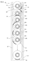
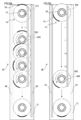
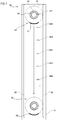
- FIG. 1 is a view showing a schematic configuration of the display device according to the exemplary embodiment of the present invention.
- FIG. 2-1 is a top view and a side view of the display device.
- FIG. 2-2 is a cross-sectional view taken along the line II2-II2 in FIG. 2-1.
- FIG. 3 is a view for explaining the container.
- FIG. 4 is a view for explaining the container.
- FIG. 5 is a view for explaining the behavior of the container in the display device.
- FIG. 6 is a view showing another example of behavior of the container.
- FIG. 7 is a view showing another example of behavior of the container.
- FIG. 8 is a view showing a modified example of the container.
- FIG. 9 is a view showing a modified example of the container.
- FIG. 10 is a view showing a modified example of the display device.
- FIG. 11 is a view showing another modified example of the container.
- FIG. 12 is a view showing another modified example of the container.
- FIG. 13 is a view for explaining the behavior of the container in the display device.
- FIG. 14 is a view showing another modified example of the container.
- FIG. 15 is a view showing another modified example of the container.
- FIG. 16 is a view for explaining the behavior of the container in the display device.
- FIG. 17 is a view for explaining the arrangement positions of the identification marks on the container.
- FIG. 18 is a view showing another modified example of the container.
- FIG. 19 is a view showing another modified example of the container.
- FIG. 20 is a view showing another modified example of the container.
- FIG. 21 is a view for explaining the behavior of the container in the display device.
- FIG. 22 is a view showing another configuration example of the container.
- FIG. 23 is a view showing another configuration example of the container.
- FIG. 24 is a view showing the behavior of the container in the display device.
- FIG. 25 is a view showing a modified example of the container.
- FIG. 26 is a view showing a modified example of the container.
- FIG. 27 is a view showing another modified example of the container.
- FIG. 28 is a view showing another modified example of the container.
- FIG. 29 is a view showing behavior of the container in the display device,
- FIG. 30 is a view showing another example of the modified examples of the container.
- FIG. 31 is a view showing another example of the modified examples of the container.
- FIG. 32 is a view illustrating an aspect of the arrangement of the first to fifth protrusions.
- FIG. 1 is a view showing a schematic configuration of a display device according to the present exemplary embodiment.
- a display device 30 includes: a placement unit 31 on which containers 20 are to be placed; and guides 32 that form a movement route (a movement path) of the containers 20, and that guide movement of the containers 20.
- the containers 20 each have a film F, with a pattern printed thereon, mounted on the outer circumferential face thereof, and filled with drink therein.
- the display device 30 also includes a regulation plate 34 that is preferably formed transparently, arranged along one side of the placement unit 31 and that stops movement of the containers 20.
- the display device 30 also includes a rotation mechanism 50 that rotates the container 20, so that an identification mark 23 attached on the container 20 is caused to face frontward.
- the display device 30 is, as shown in FIG. IB, put inside a display case 10 installed in a convenience store, a super market or the like.
- This display case 10 includes: a case main body unit 1OA formed into a rectangular parallelepiped shape; and doors 1OB provided so as to be openable and closable with respect to this case main body unit 1OA, which form the main part of the display case 10.
- the display device 30 is placed on a shelf (not shown in the figure) provided to the display case 10. On this occasion, the display device 30 is placed so that the side thereof where the regulation plate 34 is provided is located at the side where the doors 1OB are provided. Additionally, the placement unit 31 of the display device 30 is arranged so that the side thereof where the regulation plate 34 is provided is positioned at a lower level than a side thereof opposite to the side where the regulation plate 34 is provided. That is, the placement unit 31 of the display device 30 is arranged in the downward sloping state from the back side of the display case 10 toward the front side thereof (the side of a taken-out portion) from which the containers 20 are taken out.
- the display case 10 in this exemplary embodiment also has a door (not shown in the figure) provided on the back side thereof, whereby the back side becomes also openable.
- the containers 20 are supplied to the display device 30 from this back side. That is, the display case 10 has a configuration where a supplying portion for the containers 20 is provided at the back side of the display case 10, and at the back side of the display device 30.
- the containers 20 having been supplied move on the placement unit 31 toward the side of the doors 1OB. That is, the containers 20 having been supplied move toward purchasers who purchase the containers 20.
- the side where the doors 1OB are provided is sometimes referred to as a front side (frontward), whereas the side opposite to the doors 1OB is sometimes referred to as a back side (backward).
- the width direction (a direction orthogonal to a direction in which the containers 20 move) of the display case 10 is sometimes referred to as a lateral direction, or as a width direction.
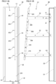
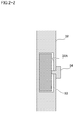
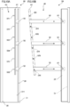
- FIG. 2-1 (FIGs. 2- IA and 2- IB) is a top view and a side view of the display device 30. Specifically, FIG. 2- IA shows a top view, and FIG. 2- IB shows a right side view. Also, FIG. 2-2 is a cross-sectional view taken along the line II2-II2 of FIG. 2- IB.
- the placement unit 31 is provided with plural roll-shaped members 311. As described specifically, the placement unit 31 is provided with a first roller array 312 formed of the plural roll-shaped members 311 arrayed in the front-back direction, and a second roller array 313 formed of the plural roll-shaped members 311 arrayed in the front-back direction in the same manner. Each of the roll-shaped members 311 is provided so as to be rotatable along the movement route of the containers 20, and smoothly moves the containers 20 frontward.
- the display device 30 includes the rotation mechanism 50 that rotates the container 20 to make the identification mark 23 attached on the container 20 face frontward, as mentioned above.
- the rotation mechanism 50 includes: a rod-shaped member 51 that is provided along the movement route of the containers 20 and above the placement unit 31; and first to sixth pins 521 to 526 that are attached to the rod- shaped member 51, and that protrude into the movement route of the containers 20.
- the first pin 521 is arranged on the most upstream side in the movement direction of the containers 20, while the sixth pin 526 is arranged on the most downstream side in the movement direction.
- the first to sixth pins 521 to 526 are arranged at regular intervals.
- the rotation mechanism 50 includes fixing members 53 that fix the rod-shaped member 51 to a guide 32 of the right-hand side.
- the rod-shaped member 51 is sloped so as to be away from the placement unit 31 toward the front.
- the first pin 521 is arranged closest to the placement unit 31, whereas the sixth pin 526 is located at a farthest position away from the placement unit 31.
- the first to sixth pins 521 to 526 are arranged in different positions with respect to one another in a height direction. Note that in FIG. 2- IB, the slope of the rod-shaped member 51 is shown as being greater than its actual slope in order to facilitate understanding.
- the fixing members 53 in this exemplary embodiment are inserted in the guide 32 of the right-hand side and are slidable with respect to the guide 32 of the right-hand side.
- the fixing members 53 may be slid with respect to the guide 32 of the right-hand side thereby to move the first to sixth pins 521 to 526 in the height direction.
- the guide 32 of the right- hand side includes holes 32A each in a rectangular form. Then, in this exemplary embodiment, the fixing members 53 are slidably inserted in the holes 32A, respectively. Then, the fixing members 53 inserted in the holes 32A may be slid thereby to move the first to sixth pins 521 to 526 in the height direction. Also, the fixing members 53 are fixed by being pressed against inner walls of the holes 32A by the screws 54, respectively.
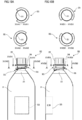
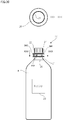
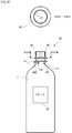
- FIG. 3 (FIGs. 3A and 3B) and FIG. 4 (FIGs. 4A and 4B) are views for explaining the container 20.
- FIG. 3A shows a front elevational view of the container 20, and FIG. 3B shows a left side view of the container 20.
- FIG. 4A shows a rear elevational view of the container 20, and FIG. 4B shows a right side view of the container 20.
- views shown in upper parts of FIGs. 3A and 3B and FIGs. 4A and 4B show cross- sectional views taken along the line IIIA-IIIA, the line IIIB-IIIB, the line IVA-IVA, and the line IVB-IVB, respectively.
- the container 20 is illustrated as a container made of a resin material such as PET (polyethylene terephthalate).
- a resin material such as PET (polyethylene terephthalate).
- an injection molding (blow molding) method using a resin material, or a method that involves molding a preform by use of a resin material and then blow- molding the preform may be used to manufacture such a container 20.
- the container 20 includes: a container body 21 that has an opening (a lip) in the upper portion thereof, and that is formed into a tubular form and filled with drink therein; and a cap 22 that closes the opening of the container body 21.
- the film F is mounted on the outer circumferential face of the container body 21.
- the diameter of the container body 21 on the upper portion side is smaller than the diameter thereof on the bottom portion side. In other words, the container body 21 is such that the upper portion side has the reduced diameter.
- the identification mark 23 for differentiating the container 20 from other products is printed on the film F, as shown in FIG. 3A.
- the container 20 includes a first projecting portion 24 that is provided at an upper part of the container body 21 (below the cap 22) and that annularly projects from the outer circumferential face of the container body 21 in the radial direction of the container body 21.
- the container 20 includes the first projecting portion 24 that is provided along the circumferential direction of the container body 21 and that is annularly formed.
- the first projecting portion 24 is integrally formed with the container body 21.
- the container 20 includes a convex portion 25 (an example of a third projecting portion) that is provided below the first projecting portion 24 and that projects into the radial direction of the container 20.
- the container 20 has the convex portion 25 at a position placed toward an outside of the container body 21 with respect to the outer circumferential face of the container body 21.
- the amount of projection of the convex portion 25 is smaller than the amount of projection of the first projecting portion 24. This instance reduces the likelihood that, when a user operates the cap 22, his or her fingers will be caught on the convex portion 25, as compared to an instance where the convex portion 25 projects beyond the first projecting portion 24. Also, as shown in the cross-sectional view of FIG.
- the convex portion 25 is provided so as to wrap around the container body 21, from the side thereof on which the identification mark 23 is provided, to the opposite side thereof to the side on which the identification mark 23 is provided.
- the convex portion 25 is provided in a clockwise direction, from the side on which the identification mark 23 is provided, toward the opposite side.
- the convex portion 25 is provided within a predetermined range in the circumferential direction of the container body 21.
- the container 20 is configured so that the convex portion 25 is not provided on a right side face of the container 20 as viewed from the side thereof on which the identification mark 23 is provided (see FIG. 3A).
- the right side face of the container 20 (a region adjacent to the convex portion 25) is such that the container body 21 is exposed.
- a configuration is such that the convex portion 25 is not provided to the container 20 at a position rightward of a tangent line (see the cross-sectional view of FIG. 3A) that is tangent to a right side face of the container body 21, that extends from a front face side of the container 20 toward a rear face side thereof, and that passes through the provided position of the above- mentioned convex portion 25 in the height direction.
- the convex portion 25 is formed at its bottom face in a stepped form, and is configured by including plural step portions. As described specifically, the convex portion 25 is formed at its bottom face in a stepped form so that its height decreases in the clockwise direction.
- the convex portion 25 in this exemplary embodiment is configured by including, in its bottom portion, first to sixth flat faces 251 to 256 (an example of a face having an intersecting relationship with the outer circumferential face of the container body 21), the positions of which are different from one another in the height direction.
- the convex portion 25 includes plural end faces, the positions of which are different from one another in the height direction and are also different from one another in the circumferential direction of the container body 21.
- a region where the convex portion 25 (the first to sixth flat faces 251 to 256) is provided may be considered as a face forming portion.
- the convex portion 25 (the first to sixth flat faces 251 to 256) may also be considered as a receiving portion that receives resistance force for rotating the container body 21 in the circumferential direction thereof, from the side of the display device 30.
- each of the first to sixth flat faces 251 to 256 is arranged so as to intersect with (be substantially orthogonal to) the outer circumferential face of the container body 21, as shown in FIG. 3 A.
- the first flat face 251 is located on the side on which the identification mark 23 is provided, as shown in FIG. 3A.
- the sixth flat face 256 is located on the opposite side to the side on which the identification mark 23 is provided, as shown in FIG. 4A.
- the second to fifth flat faces 252 to 255 are provided so that the second flat face 252, the third flat face 253, the fourth flat face 254 and the fifth flat face 255 are arranged in this order in a direction from the first flat face 251 to the sixth flat face 256.
- first to sixth flat faces 251 toward 256 are provided at intervals of a predetermined angle in the circumferential direction of the container 20. Also, the first flat face 251 is located in the lowermost portion, and the sixth flat face 256 is located in the uppermost portion.
- the above-mentioned convex portion 25 or later-described first to fifth protrusions 241 to 245 may be formed at the time of formation of the container 20. Alternatively, attachment or the like of other members such as resin pieces or metal pieces may be separately performed to form the convex portion 25 or the first to fifth protrusions 241 to 245. [0029] Description will now be given with regard to behavior of the container 20 in the display device 30.
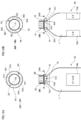
- FIG. 5 is a view for explaining the behavior of the container 20 in the display device 30. Illustration of the first roller array 312, the second roller array 313 and the fixing members 53 is omitted from FIG. 5. Also, in the following drawings, the first pin 521 and the like are shown above the first projecting portion 24 in order that the drawings may be readily seen.
- the container 20 makes circumferential rotation in sequence by the third flat face 253 engaging against the third pin 523, the fourth flat face 254 engaging against the fourth pin 524, and the fifth flat face 255 engaging against the fifth pin 525. Finally, the sixth flat face 256 engages against the sixth pin 526, so that the identification mark 23 comes to face frontward (see the reference numeral 5C). After that, the container 20 slides on the placement unit 31 and reaches the front of the display device 30.
- the identification mark 23 and the region where the convex portion 25 are arranged with a predetermined positional relationship. Also, the identification mark 23 and the region where the convex portion 25 is not provided are likewise arranged with a predetermined positional relationship. Specifically, when the identification mark 23 faces one direction, the region where the convex portion 25 is not provided faces a direction orthogonal to the one direction.
- the container 20 rotates when the identification mark 23 faces a direction other than frontward, whereas the container 20 does not rotate when the identification mark 23 faces frontward.
- the identification mark 23 ends up facing frontward when the container 20 reaches the front side of the display device 30.
- the identification mark 23 will come to face frontward.
- the positions of the first to sixth pins 521 to 526 in the height direction are adjusted in advance, although description has been omitted above. Specifically, the positions of the first to third pins 521 to 523 in the height direction are adjusted in advance so that the first pin 521 engages against the first flat face 251, so that the second pin 522 engages against the second flat face 252, and so that the third pin 523 engages against the third flat face 253. Also, the positions of the fourth to sixth pins 524 to 526 in the height direction are adjusted in advance so that the fourth pin 524 engages against the fourth flat face 254, so that the fifth pin 525 engages against the fifth flat face 255, and so that the sixth pin 526 engages against the sixth flat face 256.
- FIG. 6 (FIGs. 6A and 6B) and FIG. 7 are views showing another example of behavior of the container 20.
- the container 20 when the container 20 is supplied with the identification mark 23 facing toward the back side of the display device 30, the third flat face 253 faces toward the front of the display device 30. Then, the container 20 moves frontward, while the third flat face 253 passes above the first pin 521 and the second pin 522 (see also FIG. 2- IB). Thus, the container 20 reaches the third pin 523 without rotating. Then, the container 20 receives rotational force from the third pin 523 and thus makes rotation in the same manner as described above. Then, the container 20 reaches the front of the display device 30 with the identification mark 23 facing frontward, in the same manner as described above.
- the sixth flat face 256 faces toward the front of the display device 30. Then, the container 20 moves frontward, while the sixth flat face 256 passes above the first to fifth pins 521 to 525 (see also FIG. 2- IB). Thus, the container 20 reaches the sixth pin 526 without rotating. Then, the container 20 receives rotational force from the sixth pin 526 and thus makes rotation in the same manner as described above. Then, the container 20 reaches the front of the display device 30 with the identification mark 23 facing frontward, in the same manner as described above.
- the container 20 may be supplied with the identification mark 23 facing frontward.
- the convex portion 25 is not present on a side face of the container 20 facing the side on which the first to sixth pins 521 to 526 are arranged.
- the region (the face) where the convex portion 25 is not present is opposed to the side on which the first to sixth pins 521 to 526 are arranged.
- the first to sixth flat faces 251 to 256 that engage against the first to sixth pins 521 to 526 are not located on the right side face of the container 20 in the drawing.
- the container 20 may have the following configuration.
- FIG. 8 (FIGs. 8A and 8B) and FIG. 9 (FIGs. 9A and 9B) are views showing a modified example of the container 20.
- FIG. 8A shows a front elevational view of the container 20, and FIG. 8B shows a left side view of the container 20.
- FIG. 9A shows a rear elevational view of the container 20, and FIG. 9B shows a right side view of the container 20.
- views shown in upper parts of FIGs. 8A and 8B and FIGs. 9A and 9B show cross-sectional views taken along the line VIIIA- VIIIA, the line VIIIB-VIIIB, the line IXA-IXA, and the line IXB-IXB, respectively.
- the stepped portions of the convex portion 25 are provided on the bottom face (the bottom portion) of the convex portion 25; however, in this modified example, the stepped portions are provided on a top face (a top portion) of the convex portion 25.
- the display device 30 shown in FIG. 10 FIG. 10 (FIGs. 1OA and 10B) (a view showing a modified example of the display device 30) is used.
- the slope of the rod-shaped member 51 is made different from the slope of the rod-shaped member 51 shown in FIGs. 2-1A and 2-1B.
- the rod-shaped member 51 in this modified example is arranged so as to be closer to the placement unit 31 toward the front.
- the sixth pin 526 is arranged closest to the placement unit 31, whereas the first pin 521 is located at a farthest position away from the placement unit 31.
- FIG. 11 FIGs. HA and HB
- FIG. 12 FIG. 12A and 12B
- FIG. 1 IA shows a front elevational view of the container 20
- FIG. 1 IB shows a left side view of the container 20
- FIG. 12A shows a rear elevational view of the container 20
- FIG. 12B shows a right side view of the container 20.
- views shown in upper parts of FIGs. 1 IA and 1 IB and FIGs. 12A and 12B show cross-sectional views taken along the line XIA-XIA, the line XIB-XIB, the line XIIA-XIIA, and the line XIIB-XIIB, respectively.
- the container 20 in this modified example is provided with two identification marks 23.
- the container 20 is provided with a first identification mark 23a and a second identification mark 23b.
- the first identification mark 23a and the second identification mark 23b are arranged with their phases shifted 180 degrees in the circumferential direction of the container 20.
- the second identification mark 23b is provided on the opposite side to the side on which the first identification mark 23 a is provided.
- the container 20 according to this modified example is provided with two convex portions 25. Specifically, one of the convex portions 25 is provided above the first identification mark 23a, while the other convex portion 25 is provided above the second identification mark 23b. As further described, a configuration is such that the convex portions 25 are not provided at positions where their phases are shifted 90 degrees with respect to the first identification mark 23a and the second identification mark 23b.
- Each of the convex portions 25 is formed at its bottom face in a stepped form and includes the first to third flat faces 251 to 253 in its bottom portion, as in the case of the above.
- FIG. 13 is a view for explaining the behavior of the container 20 in the display device 30.
- the first flat face 251 of one of the two convex portions 25 faces toward the front of the display device 30. Then, the container 20 moves frontward. On this occasion, the first flat face 251 engages against the first pin 521. As a result, the container 20 rotates counterclockwise. After that, the second flat face 252 engages against the second pin 522, and thus, the container 20 further rotates. Also, the third flat face 253 engages against the third pin 523, and thus, the container 20 further rotates. Thereby, the first identification mark 23 a comes to face frontward.
- the first flat face 251 of the other of the two convex portions 25 faces toward the front of the display device 30. Then, the container 20 moves frontward. On this occasion, the first flat face 251 engages against the first pin 521. As a result, the container 20 rotates counterclockwise. After that, the second flat face 252 engages against the second pin 522, and thus, the container 20 further rotates. Also, the third flat face 253 engages against the third pin 523, and thus, the container 20 further rotates. Thereby, the second identification mark 23b comes to face frontward.
- each of the convex portions 25 is provided with three flat faces.
- the display device 30 therefore, three pins are provided corresponding to the three flat faces, respectively. That is, this modified example may reduce the number of pins, because rotation of close to 360 degrees of the container 20 is not necessary (see FIG. 5).
- a configuration is such that the rotation mechanism 50 is provided only in an upper portion of the display device 30, as shown in FIGs. 13A and 13B.
- the first to sixth pins 521 to 526 are provided on the right-hand side of the movement route of the containers 20; however, it may be desired that the first to sixth pins 521 to 526 be provided on the left-hand side of the movement route, from the viewpoint of installation space or the like.
- supply of the above-mentioned container 20 to the display device 30 having such a configuration may not lead to rotation of the container 20. Therefore, the container 20 may have the following configuration.
- FIG. 14 and FIG. 15 are views showing another modified example of the container 20.
- FIG. 14A shows a front elevational view of the container 20, and FIG. 14B shows a left side view of the container 20.
- FIG. 15A shows a rear elevational view of the container 20, and FIG. 15B shows a right side view of the container 20.
- 15A and 15B show cross sections taken along the line XIVAl -XIVAl, the line XIVA2-XIVA2, the line XIVBl -XIVBl, the line XIVB2-XIVB2, the line XVAl-XVAl, the line XVA2-XVA2, the line XVBl-XVBl, and the line XVB2-XVB2.
- the container 20 according to this modified example is provided with two convex portions 25, as in the case of the above.
- the two convex portions 25 are arranged as shifted vertically with respect to each other.
- one of the convex portions 25 is provided above, while the other convex portion 25 is provided below.
- the one convex portion 25 arranged above has the same configuration as the convex portion 25 shown in FIGs. 8 A and 8B as well as FIGs. 9 A and 9B, except for its dimension in the height direction.
- the other convex portion 25 arranged below has basically the same configuration as the convex portion 25 shown in FIGs. 3 A and 3B as well as FIGs. 4A and 4B.
- the other convex portions 25 are provided so as to wrap around the container body 21, from the side thereof on which the identification mark 23 is provided, toward the opposite side thereof to the side on which the identification mark 23 is provided.
- the other convex portion 25 arranged below is provided, from the side thereof on which the identification mark 23 is provided, in a counterclockwise direction, as distinct from the convex portion 25 positioned above.
- a configuration is such that, at the position of the lower convex portion 25 in the height direction, the convex portion 25 is not provided on a left side face of the container 20 (see FIG. 14A). As mentioned in addition, the container body 21 is exposed on this left side face thereof.
- FIG. 16 is a view for explaining the behavior of the container 20 in the display device 30.
- FIG. 16 shows the display device 30 in which the first to sixth pins 521 to 526 are provided on the left-hand side of the movement route of the containers 20.
- the container 20 when the container 20 is supplied to the display device 30 with the identification mark 23 facing diagonally forward left, the first flat face 251 of the convex portion 25 positioned below engages against the first pin 521. Thereby, rotational force is applied to the container 20, so that the container 20 makes clockwise rotation. Then, as the container 20 moves frontward, the second flat face 252 engages against the second pin 522 (see the reference numeral 16B), and thus, the container 20 likewise makes clockwise rotation.
- the container 20 makes clockwise rotation in sequence by the third flat face 253 engaging against the third pin 523, the fourth flat face 254 engaging against the fourth pin 524, and the fifth flat face 255 engaging against the fifth pin 525. Finally, the sixth flat face 256 engages against the sixth pin 526, so that the identification mark 23 faces frontward (see the reference numeral 16C). After that, the container 20 slides on the placement unit 31 and reaches the front of the display device 30 with the identification mark 23 facing frontward.
- the container 20 is not limited to being provided with one identification mark 23 but is often provided with two identification marks 23.
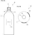
- the two provided identification marks 23 are not limited to being arranged with their phases shifted 180 degrees but may be arranged with their phases shifted degrees other than 180 degrees, as shown in FIG. 17 (FIGs. 17A and 17B) (a view for explaining the arrangement positions of the identification marks 23 on the container 20).
- Such a container 20 may be provided with the convex portions 25 in the following manner.
- FIG. 18 is a view showing another modified example of the container 20.
- FIG. 18A shows a view of the container 20 as seen from the side thereof on which the first identification mark 23a is provided
- FIG. 18B shows a view of the container 20 as seen from the side thereof on which the second identification mark 23b is provided.
- views shown in upper parts of FIGs. 18A and 18B show cross sections taken along the line XVIIIAl -XVIIIAl, the line XVIIIA2-XVIIIA2, the line XVIIIBl -XVIIIBl, and the line XVIIIB2-XVIIIB2.
- FIGs. 18A and 18B illustrate a case where the first identification mark 23a and the second identification mark 23b are arranged with their phases shifted 120 degrees.
- the container 20 according to this modified example is also provided with two convex portions 25.
- One of the convex portions 25 is arranged above, while the other convex portion 25 is arranged below. Also, the one convex portion 25 and the other convex portion 25 are provided as shifted with respect to each other in the circumferential direction of the container 20.
- Each of the two convex portions 25 has the same configuration as the convex portion 25 shown in FIGs. 3A and 3B as well as FIGs. 4A and 4B, except for its dimension in the height direction.
- the convex portion 25 positioned above is provided corresponding to the first identification mark 23a, while the convex portion 25 positioned below is provided corresponding to the second identification mark 23b.
- the convex portion 25 is not provided on a right side face of the container body 21, so that the container body 21 is exposed (see FIG. 18A). Also, at the position where the lower convex portion 25 is provided (the position thereof in the height direction), the convex portion 25 is not provided on a right side face of the container body 21, so that the container body 21 is exposed (see FIG. 18B).
- the positions of the fixing members 53 in the height direction are adjusted thereby to arrange the above-mentioned first to sixth pins 521 to 526 so as to correspond to the convex portion 25 positioned above. Then, when the container 20 is supplied to the display device 30 in this state, the first identification mark 23a comes to face frontward, as described above. Also, in order for the display device 30 to make the second identification mark 23b face frontward, the positions of the fixing members 53 in the height direction are adjusted thereby to arrange the first to sixth pins 521 to 526 so as to correspond to the convex portion 25 positioned below. Then, when the container 20 is supplied in this state, the second identification mark 23b comes to face frontward.
- the container 20 may have the following configuration.
- FIGs. 19 and 20 are views showing another modified example of the container 20.
- FIG. 19 is a front elevational view of the container 20
- FIG. 20 is a rear elevational view of the container 20.
- two views shown in an upper part of FIG. 20 show cross-sectional views taken along the line XXA-XXA and the line XXB-XXB, respectively.
- the container 20 is provided with one identification mark 23 as shown in FIG.
- the container 20 is provided with two convex portions 25 on the opposite side thereof to the side on which the identification mark 23 is provided, as shown in FIG.
- the two convex portions 25 are provided at positions such that their phases are shifted 180 degrees with respect to the identification mark 23. Also, the convex portions 25 are configured so as not be provided at positions such that their phases are shifted 90 degrees and -90 degrees with respect to the identification mark 23.
- the two convex portions 25 are arranged as vertically shifted with respect to each other. As mentioned in addition, one of the convex portions 25 is provided above, while the other convex portion 25 is provided below.
- the one convex portion 25 arranged above has the same configuration as the convex portion 25 shown in FIG. 1 IA, except for its dimension in the height direction.
- the one convex portion 25 arranged above is formed at its bottom face in a stepped form and includes the first to third flat faces 251 to 253 in its bottom portion.
- the first to third flat faces 251 to 253 are provided so that the first flat face 251, the second flat face 252 and the third flat face 253 are arranged in this order in the clockwise direction.
- the other convex portion 25 arranged below has basically the same configuration as the above-mentioned one convex portion 25 arranged above.
- the first to third flat faces 251 to 253 are provided so that the third flat face 253, the second flat face 252 and the first flat face 251 are provided in this order in the clockwise direction.
- FIG. 21 is a view for explaining the behavior of the container 20 in the display device 30.
- FIGs. 21A and 21B shows the display device 30 in which the first to third pins 521 to 523 are provided on the left-hand side of the movement route of the container 20, and the first to third pins 521 to 523 are also provided on the right-hand side of the movement route of the container 20.
- the first flat face 251 of one of the above-mentioned two convex portions 25 faces toward the front of the display device 30. Then, the container 20 moves frontward. On this occasion, the first flat face 251 engages against the first pin 521 provided on the right-hand side of the movement route. As a result, the container 20 rotates counterclockwise. After that, the second flat face 252 engages against the second pin 522 provided on the same right-hand side, and thus, the container 20 further rotates. Also, the third flat face 253 engages against the third pin 523 provided on the same right-hand side, and thus, the container 20 further rotates. Thereby, the identification mark 23 comes to face frontward.
- the first flat face 251 of the other of the above-mentioned two convex portions 25 faces toward the front of the display device 30. Then, the container 20 moves frontward. On this occasion, the first flat face 251 engages against the first pin 521 on the left-hand side of the movement route. As a result, the container 20 rotates clockwise. After that, the second flat face 252 engages against the second pin 522 on the same left-hand side, and thus, the container 20 further rotates. Also, the third flat face 253 engages against the third pin 523 on the same left-hand side, and thus, the container 20 further rotates. Thereby, the identification mark 23 comes to face frontward.
- the first to third pins 521 to 523 located on the left-hand side of the movement route are positioned below the first to third pins 521 to 523 located on the right-hand side of the movement route (on a side closer to the placement unit 31) for correspondence with the above-mentioned other convex portion 25 (the lower convex portion 25).
- FIGs. 2- IA to 4B may be adopted to make the identification mark 23 face toward the front; however, this configuration requires six pins, namely, the first to sixth pins 521 to 526, as described above. As mentioned in addition, rotation of close to 360 degrees of the container 20 is required, and therefore, the pins are arranged up to the vicinity of the taken-out portion for the containers 20, as shown also in FIGs. 2- IA and 2- IB. This situation might render it difficult to take out the containers 20. [0068] In the case of the container 20 shown in FIGs. 19 and 20, the number of pins may be reduced as compared to the configuration shown in FIGs.
- the pins may be provided for example on an upper side of the display device 30. This makes it easier to take out the containers 20. Also, when six pins, namely, the first to sixth pins 521 to 526, are required (when rotation of close to 360 degrees of the container 20 is required), the length of the display device 30 becomes longer in the front-back direction thereof. In the case of the configuration shown in FIGs. 19 to 2 IB, the container 20 has to be rotated only by 180 degrees at the maximum, and thus, the display device 30 may have a short length in the front-back direction.
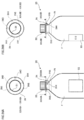
- FIG. 22 FIGs. 22A and 22B
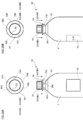
- FIG. 23 FIGs. 23A and 23B
- FIG. 22A shows a front elevational view of the container 20
- FIG. 22B shows a left side view of the container 20
- FIG. 23A shows a rear elevational view of the container 20
- FIG. 23B shows a right side view of the container 20.
- 23A and 23B show cross-sectional views taken along the line XXIIA-XXIIA, the line XXIIB-XXIIB, the line XXIIIA-XXIIIA, and the line XXIIIB- XXIIIB, respectively.
- the container 20 includes first to fifth protrusions 241 to 245 each in the form of a rod, provided below the first projecting portion 24 and projecting downward from the first projecting portion 24.
- the first to fifth protrusions 241 to 245 are provided in the circumferential direction of the container 20.
- the first to fifth protrusions 241 to 245 are provided so that the first protrusion 241, the second protrusion 242, the third protrusion 243, the fourth protrusion 244 and the fifth protrusion 245 are arranged in this order in the circumferential direction of the container 20 (in the clockwise direction). Further, the first to fifth protrusions 241 to 245 are arranged at substantially equal intervals.
- the first protrusion 241 is provided on a side closer to the side on which the identification mark 23 is provided and which is closer to the right side face of the container 20 (see FIG. 22A).
- the fifth protrusion 245 is provided on a side which is opposite to the side on which the identification mark 23 is provided and which is closer to the right side face of the container 20 (see the cross-sectional view of FIG. 22A).
- the second to fourth protrusions 242 to 244 are arranged between the first protrusion 241 and the fifth protrusion 245.
- the first protrusion 241 is largest in the amount of projection from the first projecting portion 24, which is followed by the second protrusion 242. Also, the amount of projection of the third protrusion 243 is smaller than that of the second protrusion 242, and the amount of projection of the fourth protrusion 244 is smaller than that of the third protrusion 243. The amount of projection of the fifth protrusion 245 is smallest.
- the container 20 according to this exemplary embodiment is not provided with any protrusions at a position rightward of the tangent line to the container body 21 (see also FIG. 3A).
- FIG. 24 is a view showing the behavior of the container 20 in the display device 30.
- the first protrusion 241 engages against the first pin 521.
- rotational force is applied to the container 20, so that the container 20 makes counterclockwise rotation.
- the second protrusion 242 engages against the second pin 522 (see the reference numeral 21B), and thus, the container 20 likewise makes counterclockwise rotation.
- the container 20 makes circumferential rotation in sequence by the third protrusion 243 engaging against the third pin 523, and then the fourth protrusion 244 engaging against the fourth pin 524. Finally, the fifth protrusion 245 engages against the fifth pin 525 (see the reference numeral 21C), so that the identification mark 23 comes to face frontward. After that, the container 20 slides on the placement unit 31 and reaches the front of the display device 30.
- the display device 30 shown in FIGs. 2- IA and 2- IB is used as the display device 30 shown in FIG. 24.
- the number of pins is five corresponding to the number of protrusions (the first to fifth protrusions 241 to 245).
- the container 20 may be configured in the following manner.
- FIG. 25 (FIGs. 25A and 25B) and FIG. 26 (FIGs. 26A and 26B) are views showing a modified example of the container 20.
- FIG. 25A shows a front elevational view of the container 20, and FIG. 25B shows a left side view of the container 20.
- FIG. 26A shows a rear elevational view of the container 20, and FIG. 26B shows a right side view of the container 20.
- views shown in upper parts of FIGs. 25A and 25B and FIGs. 26A and 26B show cross-sectional views taken along the line XXVA-XXVA, the line XXVB-XXVB, the line XXVIA-XXVIA, and the line XXVIB-XXVIB, respectively.
- the first to fifth protrusions 241 to 245 are each given the form of a plate (or a rib), rather than the form of a rod. Also, the first to fifth protrusions 241 to 245 are radially arranged. Also, the first to fifth protrusions 241 to 245 are supported not only by the first projecting portion 24 but also by the container body 21. Thus, in the container 20 according to this modified example, strength of the first to fifth protrusions 241 to 245 may be increased, as compared to an aspect shown in FIGs. 22A to 23B.
- the container 20 may have the following configuration.
- FIG. 27 (FIGs. 27A and 27B) and FIG. 28 (FIGs. 28A and 28B) are views of another modified example of the container 20.
- FIG. 27A shows a front elevational view of the container 20, and
- FIG. 27B shows a left side view of the container 20.
- FIG. 28A shows a rear elevational view of the container 20, and
- FIG. 28B shows a right side view of the container 20.
- 28A and 28B are cross-sectional views taken along the line XXVIIA-XXVIIA, the line XXVIIB -XXVIIB, the line XX VIII A-XX VIIIA, and the line XXVIIIB- XXVIIIB, respectively.
- the first to fifth protrusions 241 to 245 are made different from one another in height, and the first to fifth pins 521 to 525 of the display device 30 are made different from one another in height.
- the first to fifth protrusions 241 to 245 may have the same dimension in the height direction, as shown in FIGs. 27A to 28B.
- a configuration may be such that there is no difference in the dimension in the height direction among the first to fifth protrusions 241 to 245.
- the heights of the first to fifth pins 521 to 525 of the display device 30 (the heights of the first to fifth pins 521 to 525 from the placement unit 31) may be the same.
- FIG. 29 is a view showing behavior of the container 20 in the display device 30.
- the heights of the first to fifth pins 521 to 525 are not made different from one another, and thus, the first to fifth pins 521 to 525 are arranged at substantially the same height from the placement unit 31.
- the container 20 when the container 20 is supplied with the identification mark 23 facing diagonally forward right, the first protrusion 241 first engages against the first pin 521. Thereby, the container 20 makes counterclockwise rotation. After that, the container 20 makes rotation in sequence by the second protrusion 242 engaging against the second pin 522, the third protrusion 243 engaging against the third pin 523, and the fourth protrusion 244 engaging against the fourth pin 524. Then, the container 20 further rotates by the fifth protrusion 245 engaging against the fifth pin 525. As a result, the identification mark 23 comes to face frontward. [0081] Also, as shown for example in FIG.
- the container 20 may have the following configuration.
- FIG. 30 is a view showing another example of the modified examples of the container 20.
- a view shown in an upper part of FIG. 30 is a cross-sectional view taken along the line XXX-XXX.
- the container 20 shown in FIG. 30 is configured so that a second projecting portion 26 having a similar shape to the first projecting portion 24 and formed separately from the first projecting portion 24 is provided below the first to fifth protrusions 241 to 245.
- a configuration is such that the second projecting portion 26 provided along the circumferential direction of the container body 21 and annularly formed is provided at an upper part of the container body 21 and below a region where the convex portion 25 or the first to fifth protrusions 241 to 245 are provided.
- the second projecting portion 26 is provided below the opening (not shown in the figure) formed at an upper part of the container body 21. Furthermore, the second projecting portion 26 is formed into a disk shape (an annulus shape). The diameter of the second projecting portion 26 is substantially the same as that of the first projecting portion 24. Also, in FIG. 30, the first to fifth protrusions 241 to 245 as an example of the receiving portion are provided on the container body 21 side with respect to an outer peripheral portion of the first projecting portion 24 and on the container body 21 side with respect to an outer peripheral portion of the second projecting portion 26. Such a configuration makes the first to fifth protrusions 241 to 245 difficult to break or to do the like.
- a portion projecting annularly from the container body 21, as is the case with the first projecting portion 24, may be supported from below by two rails or the like, thereby to allow smooth transport of the container 20 in some cases.
- the cap 22 when the cap 22 is mounted after drink filling, it may be desired to support the first projecting portion 24 from below in some cases.
- the provision of the first to fifth protrusions 241 to 245 or the convex portion 25 might render it difficult to transport the container 20, or render it difficult to mount the cap 22.
- the provision of the second projecting portion 26 below the first to fifth protrusions 241 to 245, as is the case with this exemplary embodiment, may prevent the above-mentioned problems from arising.
- first to fifth protrusions 241 to 245 each in the form of a rod are illustrated in FIG. 30, these protrusions may be in the form of a rib, as described above. Also, a configuration may be such that the first to fifth protrusions 241 to 245 are supported by not the first projecting portion 24 but the second projecting portion 26. Also, a configuration may be such that the first to fifth protrusions 241 to 245 are supported by the container body 21, the first projecting portion 24 and the second projecting portion 26.
- the container 20 may have a shape as given below.
- FIG. 31 is a view showing another example of the modified examples of the container 20.
- a view shown in an upper part of FIG. 31 is a cross-sectional view taken along the line XXXI-XXXI.
- the first projecting portion 24 is positioned below its position shown in FIG. 30, and the first to fifth protrusions 241 to 245 are provided below the first projecting portion 24.
- the second projecting portion 26 is provided above the first projecting portion 24.
- the second projecting portion 26 is arranged with a gap between the second projecting portion 26 and the first projecting portion 24, and the gap is configured to admit the above-mentioned rails.
- the container 20 shown in FIG. 31 also may prevent the above- mentioned problems from arising.
- FIG. 31 illustrates a case where the first to fifth protrusions 241 to 245 are provided below the first projecting portion 24; however, obviously, the above-mentioned convex portion 25 may alternatively be provided below the first projecting portion 24.
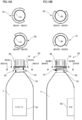
- first to fifth protrusions 241 to 245 each in the form of a rod (see FIGs. 22A to 23B) be arranged on an outer periphery side of the first projecting portion 24.
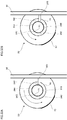
- FIG. 32B FIG. 32 (FIGs. 32A and 32B) is a view for explaining an aspect of the arrangement of the first to fifth protrusions 241 to 245.
- the first to fifth protrusions 241 to 245 are arranged on the outer periphery (the outer peripheral portion) side of the first projecting portion 24, the amount of rotation of the container 20 per one rotation may become larger as shown in FIG. 32A. As a result, an increase in the number of protrusions (the first to fifth protrusions 241 to 245) and an increase in the number of pins (the first to sixth pins 521 to 526) may be suppressed. For the same reason as described above, it is preferable that the first to fifth protrusions 241 to 245 each in the form of a rib (see FIGs. 25A to 26B) be provided extending as far as the outer periphery of the first projecting portion 24.
- the container 20 filled with drink has been described by way of example; however, the container 20 is not limited to that filled with drink.
- a container 20 filled with cosmetics, a container 20 filled with liquid soap, or the like may be given by way of example.
Landscapes
- Details Of Rigid Or Semi-Rigid Containers (AREA)
- Containers Having Bodies Formed In One Piece (AREA)
Abstract
There is provided a container which allows a cap to be mounted and the container to be transported even when a protrusion or the like used for rotating the container is provided below a projecting portion. The container 20 is provided with a second projecting portion 26, having a similar shape to a first projecting portion 24 and formed separately from the first projecting portion 24, below a first protrusion 241, a second protrusion 242, a third protrusion 243, a fourth protrusion 244 and a fifth protrusion 245. As mentioned in addition, the second projecting portion 26 provided along the circumferential direction of the container body 21 and annularly formed is provided at an upper part of the container body 21 and below a region where the convex portion 25 or the first to fifth protrusions 241 to 245 are provided.
Description
The present invention relates to a container.
When being sold, for example, in a convenience store, containers, such as PET bottles, filled with drink are placed to stand upright on a display device. There, the display device as described above is arranged, for example, in a sloping state so that each container moves frontward in the display case due to its own weight. When one container at a front side (in the front row) is taken out, other containers following that container move toward the front side due to their own weight.
Here, for example, a plastic flat plate is provided, because of good sliding of containers, to a part on which the containers are placed in the display device. Meanwhile, a display device in which a large number of rotatable rollers are arranged has been proposed in recent years (for example, refer to Patent Literature 1). Additionally, although containers are supplied from a back side of a display device in general, there is proposed a display device allowing containers to be supplied from a front side, and allowing a container, which has moved backward, to move to the front side again so as to be displayed (for example, refer to Patent Literature 2). Furthermore, with regard to a container, there has been proposed a can having inside concave portions and vertical ribs alternately formed, in a circumferential direction, in an inner circumferential wall of an annular convex portion formed on a bottom of the can (for example, refer to Patent Literature 3).
An outer face of a container is provided with a mark, such as a trade name or a trademark, in order to differentiate a product from other products. If this mark does not face a side from which a purchaser takes out the container, the purchaser finds it difficult to identify the product, and also the product does not look good when being displayed. For this reason, it is preferable that marks on displayed containers face a predetermined direction which is, for example, a front direction or the like.
The mark attached on the container can be made to face a predetermined direction by rotating the container in a circumferential direction, for example. This rotation can be performed, for example, by applying a load to a protrusion or the like that is provided at a bottom portion of a projecting portion, such as an annulus portion, formed on the container. However, the above-mentioned projecting portion may be used when a cap is mounted on the container; and in such a case, the provision of the protrusion or the like at the bottom portion of the projecting portion may make the mount of a cap to the container difficult. The above-mentioned projecting portion may be also used when the container is transported; and in such a case, the provision of the protrusion or the like at the bottom portion of the projecting portion may make this transportation difficult.
The mark attached on the container can be made to face a predetermined direction by rotating the container in a circumferential direction, for example. This rotation can be performed, for example, by applying a load to a protrusion or the like that is provided at a bottom portion of a projecting portion, such as an annulus portion, formed on the container. However, the above-mentioned projecting portion may be used when a cap is mounted on the container; and in such a case, the provision of the protrusion or the like at the bottom portion of the projecting portion may make the mount of a cap to the container difficult. The above-mentioned projecting portion may be also used when the container is transported; and in such a case, the provision of the protrusion or the like at the bottom portion of the projecting portion may make this transportation difficult.
A container to which the present invention is applied is a container that is displayable in a display device moving a displayed object to display the displayed object, the container including: a container body portion that is formed into a tubular shape and that has an outer circumferential face; a first projecting portion that projects from the outer circumferential face of the container body portion; a receiving portion that is provided below the first projecting portion and placed toward an outside of the container body portion with respect to the outer circumferential face of the container body portion, and that receives resistance force for rotating the container body portion in a circumferential direction thereof from the display device side when the container body portion moves in the display device; and a second projecting portion that is provided separately from the first projecting portion, and that projects from the outer circumferential face of the container body portion.
The second projecting portion is provided below the receiving portion or above the first projecting portion. The second projecting portion is provided along the circumferential direction of the container body portion. Further, the second projecting portion is annularly formed. The second projecting portion provided above the first projecting portion is provided in a state where there is a gap between the first projecting portion and the second projecting portion. Furthermore, the second projecting portion provided below the receiving portion is provided along the circumferential direction of the container body portion and annularly formed, the first projecting portion is provided along the circumferential direction of the container body portion and annularly formed, and the receiving portion is placed on the container body portion side with respect to an outer peripheral portion of the first projecting portion and on the container body portion side with respect to an outer peripheral portion of the second projecting portion.
According to another aspect of the present invention, a container to which the present invention is applied is a container including: a container body portion that has an outer circumferential face; a first projecting portion that projects from the outer circumferential face of the container body portion; a face forming portion that is arranged below the first projecting portion, and that is provided, in a circumferential direction of the container body portion, with a plurality of faces arranged in an intersecting relationship with the outer circumferential face and arranged toward an outside of the container body portion with respect to the outer circumferential face; and a second projecting portion that is provided in a different position from a position at which the first projecting portion is provided, and that projects from the outer circumferential face of the container body portion.
The second projecting portion is provided below the face forming portion or above the first projecting portion. The first projecting portion and the second projecting portion are provided along the circumferential direction of the container body portion and annularly formed. Further, the second projecting portion is provided at an upper part of the container body portion. The container body portion has an opening to be covered by a cap, at an upper part of the container body portion, and the second projecting portion is provided below the opening and on the upper part side of the container body portion. Moreover, the container further includes a third projecting portion that is provided so as to project from the outer circumferential face of the container body portion and be along the outer circumferential face; and the third projecting portion has a plurality of step portions on any one of a top face and a bottom face thereof, and each of the faces of the face forming portion is formed of one of the step portions of the third projecting portion.
Also, the container further includes a plurality of protrusions that project from the outer circumferential face of the container body portion and that are provided at positions different from each other in the circumferential direction of the container body portion; and each of the faces of the face forming portion is formed of one of the protrusions. Further, the first projecting portion is formed along the circumferential direction of the container body portion and annularly formed, the container further includes a plurality of protrusions that are provided so as to project from the first projecting portion in a height direction of the container body portion, and that are provided at positions different from each other in the circumferential direction of the container body portion, and each of the faces of the face forming portion is formed of one of the protrusions. The outer circumferential face of the container body portion is capable of being attached with a mark, and the face forming portion is arranged in a predetermined positional relationship with a position where the mark is to be attached.
It is possible to perform mounting of a cap and transporting a container smoothly as compared with a case where the present invention is not employed, even when a protrusion or the like is provided below a projecting portion.
Exemplary embodiments for carrying out the present invention will be described below in detail with reference to the accompanying drawings.
FIG. 1 (FIGs. 1A and 1B) is a view showing a schematic configuration of a display device according to the present exemplary embodiment.
As shown in FIG. 1A, adisplay device 30 according to this exemplary embodiment includes: a placement unit 31 on which containers 20 are to be placed; and guides 32 that form a movement route (a movement path) of the containers 20, and that guide movement of the containers 20. The containers 20 each have a film F, with a pattern printed thereon, mounted on the outer circumferential face thereof, and filled with drink therein. The display device 30 also includes a regulation plate 34 that is preferably formed transparently, arranged along one side of the placement unit 31 and that stops movement of the containers 20. The display device 30 also includes a rotation mechanism 50 that rotates the container 20, so that an identification mark 23 attached on the container 20 is caused to face frontward.
FIG. 1 (FIGs. 1A and 1B) is a view showing a schematic configuration of a display device according to the present exemplary embodiment.
As shown in FIG. 1A, a
The display device 30 is, as shown in FIG. 1B, put inside a display case 10 installed in a convenience store, a super market or the like. This display case 10 includes: a case main body unit 10A formed into a rectangular parallelepiped shape; and doors 10B provided so as to be openable and closable with respect to this case main body unit 10A, which form the main part of the display case 10.
Here, thedisplay device 30 is placed on a shelf (not shown in the figure) provided to the display case 10. On this occasion, the display device 30 is placed so that the side thereof where the regulation plate 34 is provided is located at the side where the doors 10B are provided. Additionally, the placement unit 31 of the display device 30 is arranged so that the side thereof where the regulation plate 34 is provided is positioned at a lower level than a side thereof opposite to the side where the regulation plate 34 is provided. That is, the placement unit 31 of the display device 30 is arranged in the downward sloping state from the back side of the display case 10 toward the front side thereof (the side of a taken-out portion) from which the containers 20 are taken out.
Here, the
Here, the display case 10 in this exemplary embodiment also has a door (not shown in the figure) provided on the back side thereof, whereby the back side becomes also openable. The containers 20 are supplied to the display device 30 from this back side. That is, the display case 10 has a configuration where a supplying portion for the containers 20 is provided at the back side of the display case 10, and at the back side of the display device 30. The containers 20 having been supplied move on the placement unit 31 toward the side of the doors 10B. That is, the containers 20 having been supplied move toward purchasers who purchase the containers 20. Note that, in this description of the invention, the side where the doors 10B are provided is sometimes referred to as a front side (frontward), whereas the side opposite to the doors 10B is sometimes referred to as a back side (backward). The width direction (a direction orthogonal to a direction in which the containers 20 move) of the display case 10 is sometimes referred to as a lateral direction, or as a width direction.
Description will now be given with regard to the display device 30 in more detail.
FIG. 2-1 (FIGs. 2-1A and 2-1B) is a top view and a side view of thedisplay device 30. Specifically, FIG. 2-1A shows a top view, and FIG. 2-1B shows a right side view. Also, FIG. 2-2 is a cross-sectional view taken along the line II2-II2 of FIG. 2-1B.
In thedisplay device 30 according to this exemplary embodiment, as shown in FIG. 2-1A, the placement unit 31 is provided with plural roll-shaped members 311. As described specifically, the placement unit 31 is provided with a first roller array 312 formed of the plural roll-shaped members 311 arrayed in the front-back direction, and a second roller array 313 formed of the plural roll-shaped members 311 arrayed in the front-back direction in the same manner. Each of the roll-shaped members 311 is provided so as to be rotatable along the movement route of the containers 20, and smoothly moves the containers 20 frontward.
FIG. 2-1 (FIGs. 2-1A and 2-1B) is a top view and a side view of the
In the
Also, the display device 30 includes the rotation mechanism 50 that rotates the container 20 to make the identification mark 23 attached on the container 20 face frontward, as mentioned above.
Here, as shown in FIG. 2-1A, therotation mechanism 50 includes: a rod-shaped member 51 that is provided along the movement route of the containers 20 and above the placement unit 31; and first to sixth pins 521 to 526 that are attached to the rod-shaped member 51, and that protrude into the movement route of the containers 20. Here, in this exemplary embodiment, the first pin 521 is arranged on the most upstream side in the movement direction of the containers 20, while the sixth pin 526 is arranged on the most downstream side in the movement direction. Also, the first to sixth pins 521 to 526 are arranged at regular intervals. Also, the rotation mechanism 50 includes fixing members 53 that fix the rod-shaped member 51 to a guide 32 of the right-hand side.
Here, as shown in FIG. 2-1A, the
Also, as shown in FIG. 2-1B, the rod-shaped member 51 is sloped so as to be away from the placement unit 31 toward the front. Thus, in this exemplary embodiment, the first pin 521 is arranged closest to the placement unit 31, whereas the sixth pin 526 is located at a farthest position away from the placement unit 31. As mentioned in addition, the first to sixth pins 521 to 526 are arranged in different positions with respect to one another in a height direction. Note that in FIG. 2-1B, the slope of the rod-shaped member 51 is shown as being greater than its actual slope in order to facilitate understanding.
Also, the fixing members 53 in this exemplary embodiment are inserted in the guide 32 of the right-hand side and are slidable with respect to the guide 32 of the right-hand side. Thus, in the display device 30 according to this exemplary embodiment, the fixing members 53 may be slid with respect to the guide 32 of the right-hand side thereby to move the first to sixth pins 521 to 526 in the height direction. Also, in this exemplary embodiment, there are provided screws 54 that position the respective fixing members 53 in the guide 32 of the right-hand side.
As described in further detail with reference to FIG. 2-2, the guide 32 of the right-hand side includes holes 32A each in a rectangular form. Then, in this exemplary embodiment, the fixing members 53 are slidably inserted in the holes 32A, respectively. Then, the fixing members 53 inserted in the holes 32A may be slid thereby to move the first to sixth pins 521 to 526 in the height direction. Also, the fixing members 53 are fixed by being pressed against inner walls of the holes 32A by the screws 54, respectively.
Description will now be given with regard to the container 20.
FIG. 3 (FIGs. 3A and 3B) and FIG. 4 (FIGs. 4A and 4B) are views for explaining thecontainer 20. FIG. 3A shows a front elevational view of the container 20, and FIG. 3B shows a left side view of the container 20. Also, FIG. 4A shows a rear elevational view of the container 20, and FIG. 4B shows a right side view of the container 20. Also, views shown in upper parts of FIGs. 3A and 3B and FIGs. 4A and 4B show cross-sectional views taken along the line IIIA-IIIA, the line IIIB-IIIB, the line IVA-IVA, and the line IVB-IVB, respectively.
FIG. 3 (FIGs. 3A and 3B) and FIG. 4 (FIGs. 4A and 4B) are views for explaining the
The container 20 according to this exemplary embodiment is illustrated as a container made of a resin material such as PET (polyethylene terephthalate). For example, an injection molding (blow molding) method using a resin material, or a method that involves molding a preform by use of a resin material and then blow-molding the preform may be used to manufacture such a container 20.
As shown in FIG. 3A, thecontainer 20 according to this exemplary embodiment includes: a container body 21 that has an opening (a lip) in the upper portion thereof, and that is formed into a tubular form and filled with drink therein; and a cap 22 that closes the opening of the container body 21. Also, the film F is mounted on the outer circumferential face of the container body 21. The diameter of the container body 21 on the upper portion side is smaller than the diameter thereof on the bottom portion side. In other words, the container body 21 is such that the upper portion side has the reduced diameter.
As shown in FIG. 3A, the
Here, the identification mark 23 for differentiating the container 20 from other products, such as a trade name or a trademark, is printed on the film F, as shown in FIG. 3A.
Also, thecontainer 20 includes a first projecting portion 24 that is provided at an upper part of the container body 21 (below the cap 22) and that annularly projects from the outer circumferential face of the container body 21 in the radial direction of the container body 21. As mentioned in addition, the container 20 includes the first projecting portion 24 that is provided along the circumferential direction of the container body 21 and that is annularly formed. Here, the first projecting portion 24 is integrally formed with the container body 21.
Also, the
Further, the container 20 includes a convex portion 25 (an example of a third projecting portion) that is provided below the first projecting portion 24 and that projects into the radial direction of the container 20. As mentioned in addition, the container 20 has the convex portion 25 at a position placed toward an outside of the container body 21 with respect to the outer circumferential face of the container body 21. Here, the amount of projection of the convex portion 25 is smaller than the amount of projection of the first projecting portion 24. This instance reduces the likelihood that, when a user operates the cap 22, his or her fingers will be caught on the convex portion 25, as compared to an instance where the convex portion 25 projects beyond the first projecting portion 24. Also, as shown in the cross-sectional view of FIG. 3A, the convex portion 25 is provided so as to wrap around the container body 21, from the side thereof on which the identification mark 23 is provided, to the opposite side thereof to the side on which the identification mark 23 is provided. As mentioned in addition, the convex portion 25 is provided in a clockwise direction, from the side on which the identification mark 23 is provided, toward the opposite side. As further described, the convex portion 25 is provided within a predetermined range in the circumferential direction of the container body 21.
As further described, the container 20 is configured so that the convex portion 25 is not provided on a right side face of the container 20 as viewed from the side thereof on which the identification mark 23 is provided (see FIG. 3A). As mentioned in addition, at the provided position of the convex portion 25 in the height direction, the right side face of the container 20 (a region adjacent to the convex portion 25) is such that the container body 21 is exposed. As further described, a configuration is such that the convex portion 25 is not provided to the container 20 at a position rightward of a tangent line (see the cross-sectional view of FIG. 3A) that is tangent to a right side face of the container body 21, that extends from a front face side of the container 20 toward a rear face side thereof, and that passes through the provided position of the above-mentioned convex portion 25 in the height direction.
Also, the convex portion 25 is formed at its bottom face in a stepped form, and is configured by including plural step portions. As described specifically, the convex portion 25 is formed at its bottom face in a stepped form so that its height decreases in the clockwise direction. Thus, the convex portion 25 in this exemplary embodiment is configured by including, in its bottom portion, first to sixth flat faces 251 to 256 (an example of a face having an intersecting relationship with the outer circumferential face of the container body 21), the positions of which are different from one another in the height direction. As mentioned in addition, the convex portion 25 includes plural end faces, the positions of which are different from one another in the height direction and are also different from one another in the circumferential direction of the container body 21. Here, a region where the convex portion 25 (the first to sixth flat faces 251 to 256) is provided may be considered as a face forming portion. Also, the convex portion 25 (the first to sixth flat faces 251 to 256) may also be considered as a receiving portion that receives resistance force for rotating the container body 21 in the circumferential direction thereof, from the side of the display device 30.
Here, each of the first to sixth flat faces 251 to 256 is arranged so as to intersect with (be substantially orthogonal to) the outer circumferential face of the container body 21, as shown in FIG. 3A. Also, the first flat face 251 is located on the side on which the identification mark 23 is provided, as shown in FIG. 3A. Also, the sixth flat face 256 is located on the opposite side to the side on which the identification mark 23 is provided, as shown in FIG. 4A. Also, the second to fifth flat faces 252 to 255 are provided so that the second flat face 252, the third flat face 253, the fourth flat face 254 and the fifth flat face 255 are arranged in this order in a direction from the first flat face 251 to the sixth flat face 256. Further, the first to sixth flat faces 251 toward 256 are provided at intervals of a predetermined angle in the circumferential direction of the container 20. Also, the first flat face 251 is located in the lowermost portion, and the sixth flat face 256 is located in the uppermost portion.
The above-mentioned convex portion 25 or later-described first to fifth protrusions 241 to 245 may be formed at the time of formation of the container 20. Alternatively, attachment or the like of other members such as resin pieces or metal pieces may be separately performed to form the convex portion 25 or the first to fifth protrusions 241 to 245.
Description will now be given with regard to behavior of the container 20 in the display device 30.
FIG. 5 is a view for explaining the behavior of thecontainer 20 in the display device 30. Illustration of the first roller array 312, the second roller array 313 and the fixing members 53 is omitted from FIG. 5. Also, in the following drawings, the first pin 521 and the like are shown above the first projecting portion 24 in order that the drawings may be readily seen.
FIG. 5 is a view for explaining the behavior of the
As indicated by the reference numeral 5A in FIG. 5, when the container 20 is supplied to the display device 30 with the identification mark 23 facing diagonally forward right, the first flat face 251 engages against the first pin 521. Thereby, rotational force is applied to the container 20, so that the container 20 makes counterclockwise rotation. Then, as the container 20 moves frontward, the second flat face 252 engages against the second pin 522 (see the reference numeral 5B), and thus, the container 20 likewise makes counterclockwise rotation.
After that, the container 20 makes circumferential rotation in sequence by the third flat face 253 engaging against the third pin 523, the fourth flat face 254 engaging against the fourth pin 524, and the fifth flat face 255 engaging against the fifth pin 525. Finally, the sixth flat face 256 engages against the sixth pin 526, so that the identification mark 23 comes to face frontward (see the reference numeral 5C). After that, the container 20 slides on the placement unit 31 and reaches the front of the display device 30.
In this exemplary embodiment, the identification mark 23 and the region where the convex portion 25 (the first to sixth flat faces 251 to 256) is provided are arranged with a predetermined positional relationship. Also, the identification mark 23 and the region where the convex portion 25 is not provided are likewise arranged with a predetermined positional relationship. Specifically, when the identification mark 23 faces one direction, the region where the convex portion 25 is not provided faces a direction orthogonal to the one direction.
Thus, in this exemplary embodiment, the container 20 rotates when the identification mark 23 faces a direction other than frontward, whereas the container 20 does not rotate when the identification mark 23 faces frontward. As mentioned in addition, even if the container 20 is supplied without the identification mark 23 facing frontward, the identification mark 23 ends up facing frontward when the container 20 reaches the front side of the display device 30. In other words, in this exemplary embodiment, even if the supplier who supplies the containers 20 to the display device 30 does not perform any particular operations, the identification mark 23 will come to face frontward.
Note that the positions of the first to sixth pins 521 to 526 in the height direction are adjusted in advance, although description has been omitted above. Specifically, the positions of the first to third pins 521 to 523 in the height direction are adjusted in advance so that the first pin 521 engages against the first flat face 251, so that the second pin 522 engages against the second flat face 252, and so that the third pin 523 engages against the third flat face 253. Also, the positions of the fourth to sixth pins 524 to 526 in the height direction are adjusted in advance so that the fourth pin 524 engages against the fourth flat face 254, so that the fifth pin 525 engages against the fifth flat face 255, and so that the sixth pin 526 engages against the sixth flat face 256.
Description will now be given with regard to another example of behavior of the container 20.
FIG. 6 (FIGs. 6A and 6B) and FIG. 7 are views showing another example of behavior of thecontainer 20.
As shown in FIG. 6A, when thecontainer 20 is supplied with the identification mark 23 facing toward the back side of the display device 30, the third flat face 253 faces toward the front of the display device 30. Then, the container 20 moves frontward, while the third flat face 253 passes above the first pin 521 and the second pin 522 (see also FIG. 2-1B). Thus, the container 20 reaches the third pin 523 without rotating. Then, the container 20 receives rotational force from the third pin 523 and thus makes rotation in the same manner as described above. Then, the container 20 reaches the front of the display device 30 with the identification mark 23 facing frontward, in the same manner as described above.
FIG. 6 (FIGs. 6A and 6B) and FIG. 7 are views showing another example of behavior of the
As shown in FIG. 6A, when the
Also, as shown for example in FIG. 6B, when the container 20 is supplied with the identification mark 23 facing diagonally forward left, the sixth flat face 256 faces toward the front of the display device 30. Then, the container 20 moves frontward, while the sixth flat face 256 passes above the first to fifth pins 521 to 525 (see also FIG. 2-1B). Thus, the container 20 reaches the sixth pin 526 without rotating. Then, the container 20 receives rotational force from the sixth pin 526 and thus makes rotation in the same manner as described above. Then, the container 20 reaches the front of the display device 30 with the identification mark 23 facing frontward, in the same manner as described above.
Further, as shown for example in FIG. 7, the container 20 may be supplied with the identification mark 23 facing frontward. In this case, the convex portion 25 is not present on a side face of the container 20 facing the side on which the first to sixth pins 521 to 526 are arranged. As mentioned in addition, the region (the face) where the convex portion 25 is not present is opposed to the side on which the first to sixth pins 521 to 526 are arranged. As further mentioned, the first to sixth flat faces 251 to 256 that engage against the first to sixth pins 521 to 526 are not located on the right side face of the container 20 in the drawing. Thus, the container 20 reaches the front of the display device 30 without making rotation. In other words, the container 20 reaches the front of the display device 30 while keeping its state with the identification mark 23 facing frontward.
The behavior of the container 20 in a case of one container 20 being supplied has been described above. If plural containers 20 are already displayed in the display device 30, taking out the container 20 located at the front forms space equivalent to this container 20. Then, the second container 20 moves toward this space. Then, movement of the container 20 following after the second container 20 also starts. On this occasion, each of the containers 20 is rotated by the first to sixth pins 521 to 526, and thus, the identification mark 23 of each container 20 comes to face frontward.
The container 20 may have the following configuration.
FIG. 8 (FIGs. 8A and 8B) and FIG. 9 (FIGs. 9A and 9B) are views showing a modified example of thecontainer 20. FIG. 8A shows a front elevational view of the container 20, and FIG. 8B shows a left side view of the container 20. Also, FIG. 9A shows a rear elevational view of the container 20, and FIG. 9B shows a right side view of the container 20. Also, views shown in upper parts of FIGs. 8A and 8B and FIGs. 9A and 9B show cross-sectional views taken along the line VIIIA-VIIIA, the line VIIIB-VIIIB, the line IXA-IXA, and the line IXB-IXB, respectively.
FIG. 8 (FIGs. 8A and 8B) and FIG. 9 (FIGs. 9A and 9B) are views showing a modified example of the
In the container 20 shown in FIGs. 3A and 3B as well as FIGs. 4A and 4B, the stepped portions of the convex portion 25 are provided on the bottom face (the bottom portion) of the convex portion 25; however, in this modified example, the stepped portions are provided on a top face (a top portion) of the convex portion 25. When the container 20 having such a configuration is used, the display device 30 shown in FIG. 10 (FIGs. 10A and 10B) (a view showing a modified example of the display device 30) is used.
In thisdisplay device 30, the slope of the rod-shaped member 51 is made different from the slope of the rod-shaped member 51 shown in FIGs. 2-1A and 2-1B. Specifically, the rod-shaped member 51 in this modified example is arranged so as to be closer to the placement unit 31 toward the front. Thus, in the display device 30, the sixth pin 526 is arranged closest to the placement unit 31, whereas the first pin 521 is located at a farthest position away from the placement unit 31.
In this
A modified example of the container 20 will be further described.
FIG. 11 (FIGs. 11A and 11B) and FIG. 12 (FIGs. 12A and 12B) are views of another modified example of thecontainer 20. FIG. 11A shows a front elevational view of the container 20, and FIG. 11B shows a left side view of the container 20. Also, FIG. 12A shows a rear elevational view of the container 20, and FIG. 12B shows a right side view of the container 20. Also, views shown in upper parts of FIGs. 11A and 11B and FIGs. 12A and 12B show cross-sectional views taken along the line XIA-XIA, the line XIB-XIB, the line XIIA-XIIA, and the line XIIB-XIIB, respectively.
FIG. 11 (FIGs. 11A and 11B) and FIG. 12 (FIGs. 12A and 12B) are views of another modified example of the
The container 20 in this modified example is provided with two identification marks 23. Specifically, the container 20 is provided with a first identification mark 23a and a second identification mark 23b. Here, the first identification mark 23a and the second identification mark 23b are arranged with their phases shifted 180 degrees in the circumferential direction of the container 20. As mentioned in addition, the second identification mark 23b is provided on the opposite side to the side on which the first identification mark 23a is provided.
Also, the container 20 according to this modified example is provided with two convex portions 25. Specifically, one of the convex portions 25 is provided above the first identification mark 23a, while the other convex portion 25 is provided above the second identification mark 23b. As further described, a configuration is such that the convex portions 25 are not provided at positions where their phases are shifted 90 degrees with respect to the first identification mark 23a and the second identification mark 23b. Each of the convex portions 25 is formed at its bottom face in a stepped form and includes the first to third flat faces 251 to 253 in its bottom portion, as in the case of the above.
Description will now be given with regard to behavior of the container 20 in the display device 30.
FIG. 13 (FIGs. 13A and 13B) is a view for explaining the behavior of thecontainer 20 in the display device 30.
As shown in FIG. 13A, when thecontainer 20 is supplied for example with the first identification mark 23a facing toward the back side of the display device 30, the first flat face 251 of one of the two convex portions 25 faces toward the front of the display device 30. Then, the container 20 moves frontward. On this occasion, the first flat face 251 engages against the first pin 521. As a result, the container 20 rotates counterclockwise. After that, the second flat face 252 engages against the second pin 522, and thus, the container 20 further rotates. Also, the third flat face 253 engages against the third pin 523, and thus, the container 20 further rotates. Thereby, the first identification mark 23a comes to face frontward.
FIG. 13 (FIGs. 13A and 13B) is a view for explaining the behavior of the
As shown in FIG. 13A, when the
Also, as shown in FIG. 13B, when the container 20 is supplied for example with the second identification mark 23b facing toward the back side of the display device 30, the first flat face 251 of the other of the two convex portions 25 faces toward the front of the display device 30. Then, the container 20 moves frontward. On this occasion, the first flat face 251 engages against the first pin 521. As a result, the container 20 rotates counterclockwise. After that, the second flat face 252 engages against the second pin 522, and thus, the container 20 further rotates. Also, the third flat face 253 engages against the third pin 523, and thus, the container 20 further rotates. Thereby, the second identification mark 23b comes to face frontward.
In the above-mentioned container 20, each of the convex portions 25 is provided with three flat faces. In the display device 30, therefore, three pins are provided corresponding to the three flat faces, respectively. That is, this modified example may reduce the number of pins, because rotation of close to 360 degrees of the container 20 is not necessary (see FIG. 5). As a result, a configuration is such that the rotation mechanism 50 is provided only in an upper portion of the display device 30, as shown in FIGs. 13A and 13B.
In the display device 30 shown in FIGs. 2-1A and 2-1B, the first to sixth pins 521 to 526 are provided on the right-hand side of the movement route of the containers 20; however, it may be desired that the first to sixth pins 521 to 526 be provided on the left-hand side of the movement route, from the viewpoint of installation space or the like. Incidentally, supply of the above-mentioned container 20 to the display device 30 having such a configuration may not lead to rotation of the container 20. Therefore, the container 20 may have the following configuration.
FIG. 14 (FIGs. 14A and 14B) and FIG. 15 (FIGs. 15A and 15B) are views showing another modified example of the container 20. FIG. 14A shows a front elevational view of the container 20, and FIG. 14B shows a left side view of the container 20. Also, FIG. 15A shows a rear elevational view of the container 20, and FIG. 15B shows a right side view of the container 20. Also, views shown in upper parts of FIGs. 14A and 14B and FIGs. 15A and 15B show cross sections taken along the line XIVA1-XIVA1, the line XIVA2-XIVA2, the line XIVB1-XIVB1, the line XIVB2-XIVB2, the line XVA1-XVA1, the line XVA2-XVA2, the line XVB1-XVB1, and the line XVB2-XVB2.
Here, the container 20 according to this modified example is provided with two convex portions 25, as in the case of the above. However, the two convex portions 25 are arranged as shifted vertically with respect to each other. As mentioned in addition, one of the convex portions 25 is provided above, while the other convex portion 25 is provided below.
Here, the one convex portion 25 arranged above has the same configuration as the convex portion 25 shown in FIGs. 8A and 8B as well as FIGs. 9A and 9B, except for its dimension in the height direction.
Also, the otherconvex portion 25 arranged below has basically the same configuration as the convex portion 25 shown in FIGs. 3A and 3B as well as FIGs. 4A and 4B. In other words, the other convex portions 25 are provided so as to wrap around the container body 21, from the side thereof on which the identification mark 23 is provided, toward the opposite side thereof to the side on which the identification mark 23 is provided.
However, the otherconvex portion 25 arranged below is provided, from the side thereof on which the identification mark 23 is provided, in a counterclockwise direction, as distinct from the convex portion 25 positioned above. As further described, a configuration is such that, at the position of the lower convex portion 25 in the height direction, the convex portion 25 is not provided on a left side face of the container 20 (see FIG. 14A). As mentioned in addition, the container body 21 is exposed on this left side face thereof.
Also, the other
However, the other
Description will now be given with regard to behavior of the container 20 in the display device 30.
FIG. 16 is a view for explaining the behavior of thecontainer 20 in the display device 30. Here, FIG. 16 shows the display device 30 in which the first to sixth pins 521 to 526 are provided on the left-hand side of the movement route of the containers 20.
As indicated by thereference numeral 16A in FIG. 16, when the container 20 is supplied to the display device 30 with the identification mark 23 facing diagonally forward left, the first flat face 251 of the convex portion 25 positioned below engages against the first pin 521. Thereby, rotational force is applied to the container 20, so that the container 20 makes clockwise rotation. Then, as the container 20 moves frontward, the second flat face 252 engages against the second pin 522 (see the reference numeral 16B), and thus, the container 20 likewise makes clockwise rotation.
FIG. 16 is a view for explaining the behavior of the
As indicated by the
After that, the container 20 makes clockwise rotation in sequence by the third flat face 253 engaging against the third pin 523, the fourth flat face 254 engaging against the fourth pin 524, and the fifth flat face 255 engaging against the fifth pin 525. Finally, the sixth flat face 256 engages against the sixth pin 526, so that the identification mark 23 faces frontward (see the reference numeral 16C). After that, the container 20 slides on the placement unit 31 and reaches the front of the display device 30 with the identification mark 23 facing frontward.
Note that if the first to sixth pins 521 to 526 are provided at positions corresponding to the upper convex portion 25, the above-mentioned rotation of the container 20 is unfeasible. Thus, when the first to sixth pins 521 to 526 are provided on the left-hand side of the movement route of the containers 20, it is required that the positions of the first to sixth pins 521 to 526 (the fixing members 53) be adjusted so that the first to sixth pins 521 to 526 correspond to the lower convex portion 25.
Incidentally, the container 20 is not limited to being provided with one identification mark 23 but is often provided with two identification marks 23. Also, the two provided identification marks 23 are not limited to being arranged with their phases shifted 180 degrees but may be arranged with their phases shifted degrees other than 180 degrees, as shown in FIG. 17 (FIGs. 17A and 17B) (a view for explaining the arrangement positions of the identification marks 23 on the container 20). Such a container 20 may be provided with the convex portions 25 in the following manner.
FIG. 18 (FIGs. 18A and 18B) is a view showing another modified example of the container 20.
Here, thecontainer 20 in FIGs. 18A and 18B is provided with two identification marks 23, namely, the first identification mark 23a and the second identification mark 23b. FIG. 18A shows a view of the container 20 as seen from the side thereof on which the first identification mark 23a is provided, and FIG. 18B shows a view of the container 20 as seen from the side thereof on which the second identification mark 23b is provided. Also, views shown in upper parts of FIGs. 18A and 18B show cross sections taken along the line XVIIIA1-XVIIIA1, the line XVIIIA2-XVIIIA2, the line XVIIIB1-XVIIIB1, and the line XVIIIB2-XVIIIB2. Here, FIGs. 18A and 18B illustrate a case where the first identification mark 23a and the second identification mark 23b are arranged with their phases shifted 120 degrees.
Here, the
The container 20 according to this modified example is also provided with two convex portions 25. One of the convex portions 25 is arranged above, while the other convex portion 25 is arranged below. Also, the one convex portion 25 and the other convex portion 25 are provided as shifted with respect to each other in the circumferential direction of the container 20. Each of the two convex portions 25 has the same configuration as the convex portion 25 shown in FIGs. 3A and 3B as well as FIGs. 4A and 4B, except for its dimension in the height direction.
Also, the convex portion 25 positioned above is provided corresponding to the first identification mark 23a, while the convex portion 25 positioned below is provided corresponding to the second identification mark 23b.
Thus, at the position where the upperconvex portion 25 is provided (the position thereof in the height direction), the convex portion 25 is not provided on a right side face of the container body 21, so that the container body 21 is exposed (see FIG. 18A). Also, at the position where the lower convex portion 25 is provided (the position thereof in the height direction), the convex portion 25 is not provided on a right side face of the container body 21, so that the container body 21 is exposed (see FIG. 18B).
Thus, at the position where the upper
Here, in order for the display device 30 to make the first identification mark 23a face frontward, the positions of the fixing members 53 in the height direction are adjusted thereby to arrange the above-mentioned first to sixth pins 521 to 526 so as to correspond to the convex portion 25 positioned above. Then, when the container 20 is supplied to the display device 30 in this state, the first identification mark 23a comes to face frontward, as described above. Also, in order for the display device 30 to make the second identification mark 23b face frontward, the positions of the fixing members 53 in the height direction are adjusted thereby to arrange the first to sixth pins 521 to 526 so as to correspond to the convex portion 25 positioned below. Then, when the container 20 is supplied in this state, the second identification mark 23b comes to face frontward.
Alternatively, the container 20 may have the following configuration.
FIGs. 19 and 20 are views showing another modified example of thecontainer 20. FIG. 19 is a front elevational view of the container 20, and FIG. 20 is a rear elevational view of the container 20. Also, two views shown in an upper part of FIG. 20 show cross-sectional views taken along the line XXA-XXA and the line XXB-XXB, respectively.
FIGs. 19 and 20 are views showing another modified example of the
Here, the container 20 is provided with one identification mark 23 as shown in FIG. 19, and is provided with the first projecting portion 24 as in the case of the above. Further, the container 20 is provided with two convex portions 25 on the opposite side thereof to the side on which the identification mark 23 is provided, as shown in FIG. 20. As further described, the two convex portions 25 are provided at positions such that their phases are shifted 180 degrees with respect to the identification mark 23. Also, the convex portions 25 are configured so as not be provided at positions such that their phases are shifted 90 degrees and -90 degrees with respect to the identification mark 23.
The two convex portions 25 are arranged as vertically shifted with respect to each other. As mentioned in addition, one of the convex portions 25 is provided above, while the other convex portion 25 is provided below.
Here, the oneconvex portion 25 arranged above has the same configuration as the convex portion 25 shown in FIG. 11A, except for its dimension in the height direction. Specifically, the one convex portion 25 arranged above is formed at its bottom face in a stepped form and includes the first to third flat faces 251 to 253 in its bottom portion. As further described also with reference to the cross-sectional view taken along the line XXA-XXA, the first to third flat faces 251 to 253 are provided so that the first flat face 251, the second flat face 252 and the third flat face 253 are arranged in this order in the clockwise direction.
Here, the one
Also, the other convex portion 25 arranged below has basically the same configuration as the above-mentioned one convex portion 25 arranged above. However, as shown in the cross-sectional view taken along the line XXB-XXB, the first to third flat faces 251 to 253 are provided so that the third flat face 253, the second flat face 252 and the first flat face 251 are provided in this order in the clockwise direction.
Description will now be given with regard to behavior of the container 20 in the display device 30.
FIG. 21 (FIGs. 21A and 21B) is a view for explaining the behavior of thecontainer 20 in the display device 30. Here, FIGs. 21A and 21B shows the display device 30 in which the first to third pins 521 to 523 are provided on the left-hand side of the movement route of the container 20, and the first to third pins 521 to 523 are also provided on the right-hand side of the movement route of the container 20.
FIG. 21 (FIGs. 21A and 21B) is a view for explaining the behavior of the
As shown in FIG. 21A, when the container 20 is supplied for example with the identification mark 23 facing toward the left side and the back side of the display device 30, the first flat face 251 of one of the above-mentioned two convex portions 25 (the upper convex portion 25) faces toward the front of the display device 30. Then, the container 20 moves frontward. On this occasion, the first flat face 251 engages against the first pin 521 provided on the right-hand side of the movement route. As a result, the container 20 rotates counterclockwise. After that, the second flat face 252 engages against the second pin 522 provided on the same right-hand side, and thus, the container 20 further rotates. Also, the third flat face 253 engages against the third pin 523 provided on the same right-hand side, and thus, the container 20 further rotates. Thereby, the identification mark 23 comes to face frontward.
Also, as shown in FIG. 21B, when the container 20 is supplied for example with the identification mark 23 facing toward the right side and the back side of the display device 30, the first flat face 251 of the other of the above-mentioned two convex portions 25 (the lower convex portion 25) faces toward the front of the display device 30. Then, the container 20 moves frontward. On this occasion, the first flat face 251 engages against the first pin 521 on the left-hand side of the movement route. As a result, the container 20 rotates clockwise. After that, the second flat face 252 engages against the second pin 522 on the same left-hand side, and thus, the container 20 further rotates. Also, the third flat face 253 engages against the third pin 523 on the same left-hand side, and thus, the container 20 further rotates. Thereby, the identification mark 23 comes to face frontward.
Here, the first to third pins 521 to 523 located on the left-hand side of the movement route are positioned below the first to third pins 521 to 523 located on the right-hand side of the movement route (on a side closer to the placement unit 31) for correspondence with the above-mentioned other convex portion 25 (the lower convex portion 25).
In the case of the container 20 provided with one identification mark 23, the configuration shown in FIGs. 2-1A to 4B may be adopted to make the identification mark 23 face toward the front; however, this configuration requires six pins, namely, the first to sixth pins 521 to 526, as described above. As mentioned in addition, rotation of close to 360 degrees of the container 20 is required, and therefore, the pins are arranged up to the vicinity of the taken-out portion for the containers 20, as shown also in FIGs. 2-1A and 2-1B. This situation might render it difficult to take out the containers 20.
In the case of the container 20 shown in FIGs. 19 and 20, the number of pins may be reduced as compared to the configuration shown in FIGs. 2-1A and 2-1B, and the pins may be provided for example on an upper side of the display device 30. This makes it easier to take out the containers 20. Also, when six pins, namely, the first to sixth pins 521 to 526, are required (when rotation of close to 360 degrees of the container 20 is required), the length of the display device 30 becomes longer in the front-back direction thereof. In the case of the configuration shown in FIGs. 19 to 21B, the container 20 has to be rotated only by 180 degrees at the maximum, and thus, the display device 30 may have a short length in the front-back direction.
Description has been given above with regard to an example in which the convex portion 25 is used to make the identification mark 23 of the container 20 face frontward. Incidentally, the container 20 may be configured in the following manner.
FIG. 22 (FIGs. 22A and 22B) and FIG. 23 (FIGs. 23A and 23B) are views showing another configuration example of thecontainer 20. FIG. 22A shows a front elevational view of the container 20, and FIG. 22B shows a left side view of the container 20. Also, FIG. 23A shows a rear elevational view of the container 20, and FIG. 23B shows a right side view of the container 20. Also, views shown in upper parts of FIGs. 22A and 22B and FIGs. 23A and 23B show cross-sectional views taken along the line XXIIA-XXIIA, the line XXIIB-XXIIB, the line XXIIIA-XXIIIA, and the line XXIIIB-XXIIIB, respectively.
FIG. 22 (FIGs. 22A and 22B) and FIG. 23 (FIGs. 23A and 23B) are views showing another configuration example of the
The container 20 according to this exemplary embodiment includes first to fifth protrusions 241 to 245 each in the form of a rod, provided below the first projecting portion 24 and projecting downward from the first projecting portion 24. Here, the first to fifth protrusions 241 to 245 are provided in the circumferential direction of the container 20. Also, the first to fifth protrusions 241 to 245 are provided so that the first protrusion 241, the second protrusion 242, the third protrusion 243, the fourth protrusion 244 and the fifth protrusion 245 are arranged in this order in the circumferential direction of the container 20 (in the clockwise direction). Further, the first to fifth protrusions 241 to 245 are arranged at substantially equal intervals.
Also, the first protrusion 241 is provided on a side closer to the side on which the identification mark 23 is provided and which is closer to the right side face of the container 20 (see FIG. 22A). Also, the fifth protrusion 245 is provided on a side which is opposite to the side on which the identification mark 23 is provided and which is closer to the right side face of the container 20 (see the cross-sectional view of FIG. 22A). Also, the second to fourth protrusions 242 to 244 are arranged between the first protrusion 241 and the fifth protrusion 245.
Further, the first protrusion 241 is largest in the amount of projection from the first projecting portion 24, which is followed by the second protrusion 242. Also, the amount of projection of the third protrusion 243 is smaller than that of the second protrusion 242, and the amount of projection of the fourth protrusion 244 is smaller than that of the third protrusion 243. The amount of projection of the fifth protrusion 245 is smallest. The container 20 according to this exemplary embodiment is not provided with any protrusions at a position rightward of the tangent line to the container body 21 (see also FIG. 3A).
Description will now be given with regard to behavior of the container 20 according to this exemplary embodiment.
FIG. 24 is a view showing the behavior of thecontainer 20 in the display device 30. As indicated for example by the reference numeral 21A in FIG. 24, when the container 20 is supplied to the display device 30 with the identification mark 23 facing diagonally forward right, the first protrusion 241 engages against the first pin 521. Thereby, rotational force is applied to the container 20, so that the container 20 makes counterclockwise rotation. Then, as the container 20 moves frontward, the second protrusion 242 engages against the second pin 522 (see the reference numeral 21B), and thus, the container 20 likewise makes counterclockwise rotation.
FIG. 24 is a view showing the behavior of the
After that, the container 20 makes circumferential rotation in sequence by the third protrusion 243 engaging against the third pin 523, and then the fourth protrusion 244 engaging against the fourth pin 524. Finally, the fifth protrusion 245 engages against the fifth pin 525 (see the reference numeral 21C), so that the identification mark 23 comes to face frontward. After that, the container 20 slides on the placement unit 31 and reaches the front of the display device 30. Here, the display device 30 shown in FIGs. 2-1A and 2-1B is used as the display device 30 shown in FIG. 24. In the display device 30, the number of pins is five corresponding to the number of protrusions (the first to fifth protrusions 241 to 245). In this exemplary embodiment, description has been given by taking a case where five protrusions, namely, the first to fifth protrusions 241 to 245, and five pins, namely, the first to fifth pins 521 to 525, are provided, as an example; however, the numbers of protrusions and pins may be appropriately increased.
The container 20 may be configured in the following manner.
FIG. 25 (FIGs. 25A and 25B) and FIG. 26 (FIGs. 26A and 26B) are views showing a modified example of thecontainer 20. FIG. 25A shows a front elevational view of the container 20, and FIG. 25B shows a left side view of the container 20. Also, FIG. 26A shows a rear elevational view of the container 20, and FIG. 26B shows a right side view of the container 20. Also, views shown in upper parts of FIGs. 25A and 25B and FIGs. 26A and 26B show cross-sectional views taken along the line XXVA-XXVA, the line XXVB-XXVB, the line XXVIA-XXVIA, and the line XXVIB-XXVIB, respectively.
FIG. 25 (FIGs. 25A and 25B) and FIG. 26 (FIGs. 26A and 26B) are views showing a modified example of the
In the container 20 shown in these figures, the first to fifth protrusions 241 to 245 are each given the form of a plate (or a rib), rather than the form of a rod. Also, the first to fifth protrusions 241 to 245 are radially arranged. Also, the first to fifth protrusions 241 to 245 are supported not only by the first projecting portion 24 but also by the container body 21. Thus, in the container 20 according to this modified example, strength of the first to fifth protrusions 241 to 245 may be increased, as compared to an aspect shown in FIGs. 22A to 23B.
Further, the container 20 may have the following configuration.
FIG. 27 (FIGs. 27A and 27B) and FIG. 28 (FIGs. 28A and 28B) are views of another modified example of thecontainer 20. FIG. 27A shows a front elevational view of the container 20, and FIG. 27B shows a left side view of the container 20. Also, FIG. 28A shows a rear elevational view of the container 20, and FIG. 28B shows a right side view of the container 20. Also, views shown in upper parts of FIGs. 27A and 27B and FIGs. 28A and 28B are cross-sectional views taken along the line XXVIIA-XXVIIA, the line XXVIIB-XXVIIB, the line XXVIIIA-XXVIIIA, and the line XXVIIIB-XXVIIIB, respectively.
FIG. 27 (FIGs. 27A and 27B) and FIG. 28 (FIGs. 28A and 28B) are views of another modified example of the
In the above FIGs. 22A to 26B, the first to fifth protrusions 241 to 245 are made different from one another in height, and the first to fifth pins 521 to 525 of the display device 30 are made different from one another in height. Meanwhile, the first to fifth protrusions 241 to 245 may have the same dimension in the height direction, as shown in FIGs. 27A to 28B. In other words, a configuration may be such that there is no difference in the dimension in the height direction among the first to fifth protrusions 241 to 245. Also, the heights of the first to fifth pins 521 to 525 of the display device 30 (the heights of the first to fifth pins 521 to 525 from the placement unit 31) may be the same.
Here, FIG. 29 (FIGs. 29A and 29B) is a view showing behavior of the container 20 in the display device 30. In the display device 30 in FIGs. 29A and 29B, the heights of the first to fifth pins 521 to 525 are not made different from one another, and thus, the first to fifth pins 521 to 525 are arranged at substantially the same height from the placement unit 31.
Here, as shown for example in FIG. 29A, when the container 20 is supplied with the identification mark 23 facing diagonally forward right, the first protrusion 241 first engages against the first pin 521. Thereby, the container 20 makes counterclockwise rotation. After that, the container 20 makes rotation in sequence by the second protrusion 242 engaging against the second pin 522, the third protrusion 243 engaging against the third pin 523, and the fourth protrusion 244 engaging against the fourth pin 524. Then, the container 20 further rotates by the fifth protrusion 245 engaging against the fifth pin 525. As a result, the identification mark 23 comes to face frontward.
Also, as shown for example in FIG. 29B, when the container 20 is supplied with the identification mark 23 facing backward, the third protrusion 243 first engages against the first pin 521. Thereby, the container 20 makes counterclockwise rotation. After that, the container 20 makes rotation in sequence by the fourth protrusion 244 engaging against the second pin 522, and the fifth protrusion 245 engaging against the third pin 523. Thereby, the identification mark 23 comes to face frontward. Then, in this case, a portion where the first to fifth protrusions 241 to 245 are not provided is in such a position to face the side on which the first to fifth pins 521 to 525 are arranged. As a result, the container 20 moves frontward without engaging against the remaining fourth and fifth pins 524 and 525.
Also, the container 20 may have the following configuration.
FIG. 30 is a view showing another example of the modified examples of thecontainer 20. A view shown in an upper part of FIG. 30 is a cross-sectional view taken along the line XXX-XXX.
Thecontainer 20 shown in FIG. 30 is configured so that a second projecting portion 26 having a similar shape to the first projecting portion 24 and formed separately from the first projecting portion 24 is provided below the first to fifth protrusions 241 to 245. As mentioned in addition, a configuration is such that the second projecting portion 26 provided along the circumferential direction of the container body 21 and annularly formed is provided at an upper part of the container body 21 and below a region where the convex portion 25 or the first to fifth protrusions 241 to 245 are provided.
FIG. 30 is a view showing another example of the modified examples of the
The
As further described, the second projecting portion 26 is provided below the opening (not shown in the figure) formed at an upper part of the container body 21. Furthermore, the second projecting portion 26 is formed into a disk shape (an annulus shape). The diameter of the second projecting portion 26 is substantially the same as that of the first projecting portion 24. Also, in FIG. 30, the first to fifth protrusions 241 to 245 as an example of the receiving portion are provided on the container body 21 side with respect to an outer peripheral portion of the first projecting portion 24 and on the container body 21 side with respect to an outer peripheral portion of the second projecting portion 26. Such a configuration makes the first to fifth protrusions 241 to 245 difficult to break or to do the like.
Here, a portion projecting annularly from the container body 21, as is the case with the first projecting portion 24, may be supported from below by two rails or the like, thereby to allow smooth transport of the container 20 in some cases. Also, when the cap 22 is mounted after drink filling, it may be desired to support the first projecting portion 24 from below in some cases.
In such a case, the provision of the first tofifth protrusions 241 to 245 or the convex portion 25 might render it difficult to transport the container 20, or render it difficult to mount the cap 22. The provision of the second projecting portion 26 below the first to fifth protrusions 241 to 245, as is the case with this exemplary embodiment, may prevent the above-mentioned problems from arising.
In such a case, the provision of the first to
Although the first to fifth protrusions 241 to 245 each in the form of a rod are illustrated in FIG. 30, these protrusions may be in the form of a rib, as described above. Also, a configuration may be such that the first to fifth protrusions 241 to 245 are supported by not the first projecting portion 24 but the second projecting portion 26. Also, a configuration may be such that the first to fifth protrusions 241 to 245 are supported by the container body 21, the first projecting portion 24 and the second projecting portion 26.
The container 20 may have a shape as given below.
FIG. 31 is a view showing another example of the modified examples of thecontainer 20. A view shown in an upper part of FIG. 31 is a cross-sectional view taken along the line XXXI-XXXI.
FIG. 31 is a view showing another example of the modified examples of the
In the container 20 shown in FIG. 31, the first projecting portion 24 is positioned below its position shown in FIG. 30, and the first to fifth protrusions 241 to 245 are provided below the first projecting portion 24. Also, in the container 20, the second projecting portion 26 is provided above the first projecting portion 24. Here, the second projecting portion 26 is arranged with a gap between the second projecting portion 26 and the first projecting portion 24, and the gap is configured to admit the above-mentioned rails. The container 20 shown in FIG. 31 also may prevent the above-mentioned problems from arising. FIG. 31 illustrates a case where the first to fifth protrusions 241 to 245 are provided below the first projecting portion 24; however, obviously, the above-mentioned convex portion 25 may alternatively be provided below the first projecting portion 24.
It is preferable that the above-described first to fifth protrusions 241 to 245 each in the form of a rod (see FIGs. 22A to 23B) be arranged on an outer periphery side of the first projecting portion 24. For example, if the first to fifth protrusions 241 to 245 are arranged near the container body 21 as shown in FIG. 32B (FIG. 32 (FIGs. 32A and 32B) is a view for explaining an aspect of the arrangement of the first to fifth protrusions 241 to 245.), the amount of rotation of the container 20 per one rotation becomes small.
On the other hand, when the first to fifth protrusions 241 to 245 are arranged on the outer periphery (the outer peripheral portion) side of the first projecting portion 24, the amount of rotation of the container 20 per one rotation may become larger as shown in FIG. 32A. As a result, an increase in the number of protrusions (the first to fifth protrusions 241 to 245) and an increase in the number of pins (the first to sixth pins 521 to 526) may be suppressed. For the same reason as described above, it is preferable that the first to fifth protrusions 241 to 245 each in the form of a rib (see FIGs. 25A to 26B) be provided extending as far as the outer periphery of the first projecting portion 24.
In the above-described configurations, the container 20 filled with drink has been described by way of example; however, the container 20 is not limited to that filled with drink. For example, a container 20 filled with cosmetics, a container 20 filled with liquid soap, or the like may be given by way of example.
20 Container
21 Container body
22 Cap
23 Identification mark
24 First projecting portion
25 Convex portion
26 Second projecting portion
30 Display device
241 First protrusion
242 Second protrusion
243 Third protrusion
244 Fourth protrusion
245 Fifth protrusion
251 First flat face
252 Second flat face
253 Third flat face
254 Fourth flat face
255 Fifth flat face
256 Sixth flat face
21 Container body
22 Cap
23 Identification mark
24 First projecting portion
25 Convex portion
26 Second projecting portion
30 Display device
241 First protrusion
242 Second protrusion
243 Third protrusion
244 Fourth protrusion
245 Fifth protrusion
251 First flat face
252 Second flat face
253 Third flat face
254 Fourth flat face
255 Fifth flat face
256 Sixth flat face
Claims (15)
- A container that is displayable in a display device moving a displayed object to display the displayed object, the container comprising:
a container body portion that is formed into a tubular shape and that has an outer circumferential face;
a first projecting portion that projects from the outer circumferential face of the container body portion;
a receiving portion that is provided below the first projecting portion and placed toward an outside of the container body portion with respect to the outer circumferential face of the container body portion, and that receives resistance force for rotating the container body portion in a circumferential direction thereof from the display device side when the container body portion moves in the display device; and
a second projecting portion that is provided separately from the first projecting portion, and that projects from the outer circumferential face of the container body portion. - The container according to claim 1, wherein the second projecting portion is provided below the receiving portion or above the first projecting portion.
- The container according to any one of claims 1 and 2, wherein the second projecting portion is provided along the circumferential direction of the container body portion.
- The container according to claim 3, wherein the second projecting portion is annularly formed.
- The container according to any one of claims 1 to 4, wherein the second projecting portion provided above the first projecting portion is provided in a state where there is a gap between the first projecting portion and the second projecting portion.
- The container according to claim 1, wherein
the second projecting portion provided below the receiving portion is provided along the circumferential direction of the container body portion and annularly formed,
the first projecting portion is provided along the circumferential direction of the container body portion and annularly formed, and
the receiving portion is placed on the container body portion side with respect to an outer peripheral portion of the first projecting portion and on the container body portion side with respect to an outer peripheral portion of the second projecting portion. - A container comprising:
a container body portion that has an outer circumferential face;
a first projecting portion that projects from the outer circumferential face of the container body portion;
a face forming portion that is arranged below the first projecting portion, and that is provided, in a circumferential direction of the container body portion, with a plurality of faces arranged in an intersecting relationship with the outer circumferential face and arranged toward an outside of the container body portion with respect to the outer circumferential face; and
a second projecting portion that is provided in a different position from a position at which the first projecting portion is provided, and that projects from the outer circumferential face of the container body portion. - The container according to claim 7, wherein the second projecting portion is provided below the face forming portion or above the first projecting portion.
- The container according to any one of claims 7 and 8, wherein the first projecting portion and the second projecting portion are provided along the circumferential direction of the container body portion and annularly formed.
- The container according to any one of claims 7 to 9, wherein the second projecting portion is provided at an upper part of the container body portion.
- The container according to any one of claims 7 to 9, wherein
the container body portion has an opening to be covered by a cap, at an upper part of the container body portion, and
the second projecting portion is provided below the opening and on the upper part side of the container body portion. - The container according to any one of claims 7 to 11, further comprising a third projecting portion that is provided so as to project from the outer circumferential face of the container body portion and be along the outer circumferential face, wherein
the third projecting portion has a plurality of step portions on any one of a top face and a bottom face thereof, and
each of the faces of the face forming portion is formed of one of the step portions of the third projecting portion. - The container according to any one of claims 7 to 11, further comprising a plurality of protrusions that project from the outer circumferential face of the container body portion and that are provided at positions different from each other in the circumferential direction of the container body portion, wherein
each of the faces of the face forming portion is formed of one of the protrusions. - The container according to any one of claims 7 to 11, wherein
the first projecting portion is formed along the circumferential direction of the container body portion and annularly formed,
the container further comprises a plurality of protrusions that are provided so as to project from the first projecting portion in a height direction of the container body portion, and that are provided at positions different from each other in the circumferential direction of the container body portion, and
each of the faces of the face forming portion is formed of one of the protrusions. - The container according to any one of claims 7 to 14, wherein
the outer circumferential face of the container body portion is capable of being attached with a mark, and
the face forming portion is arranged in a predetermined positional relationship with a position where the mark is to be attached.
Applications Claiming Priority (2)
| Application Number | Priority Date | Filing Date | Title |
|---|---|---|---|
| JP2009132771 | 2009-06-02 | ||
| JP2009-132771 | 2009-06-02 |
Publications (1)
| Publication Number | Publication Date |
|---|---|
| WO2010140326A1 true WO2010140326A1 (en) | 2010-12-09 |
Family
ID=43297469
Family Applications (1)
| Application Number | Title | Priority Date | Filing Date |
|---|---|---|---|
| PCT/JP2010/003587 Ceased WO2010140326A1 (en) | 2009-06-02 | 2010-05-28 | Container |
Country Status (3)
| Country | Link |
|---|---|
| JP (1) | JP2011011823A (en) |
| TW (1) | TW201105274A (en) |
| WO (1) | WO2010140326A1 (en) |
Citations (4)
| Publication number | Priority date | Publication date | Assignee | Title |
|---|---|---|---|---|
| JPS6193093A (en) * | 1984-10-01 | 1986-05-12 | 日本クラウンコルク株式会社 | Method of sealing resin bottle |
| JP2004224414A (en) * | 2003-01-24 | 2004-08-12 | Yoshino Kogyosho Co Ltd | Bottle mouth structure and cap tightening device |
| JP2007112486A (en) * | 2005-10-21 | 2007-05-10 | Yoshino Kogyosho Co Ltd | Synthetic resin container |
| JP2007223666A (en) * | 2006-02-27 | 2007-09-06 | Yoshino Kogyosho Co Ltd | Synthetic resin bottle |
-
2010
- 2010-05-27 JP JP2010121577A patent/JP2011011823A/en active Pending
- 2010-05-28 WO PCT/JP2010/003587 patent/WO2010140326A1/en not_active Ceased
- 2010-05-31 TW TW99117419A patent/TW201105274A/en unknown
Patent Citations (4)
| Publication number | Priority date | Publication date | Assignee | Title |
|---|---|---|---|---|
| JPS6193093A (en) * | 1984-10-01 | 1986-05-12 | 日本クラウンコルク株式会社 | Method of sealing resin bottle |
| JP2004224414A (en) * | 2003-01-24 | 2004-08-12 | Yoshino Kogyosho Co Ltd | Bottle mouth structure and cap tightening device |
| JP2007112486A (en) * | 2005-10-21 | 2007-05-10 | Yoshino Kogyosho Co Ltd | Synthetic resin container |
| JP2007223666A (en) * | 2006-02-27 | 2007-09-06 | Yoshino Kogyosho Co Ltd | Synthetic resin bottle |
Also Published As
| Publication number | Publication date |
|---|---|
| JP2011011823A (en) | 2011-01-20 |
| TW201105274A (en) | 2011-02-16 |
Similar Documents
| Publication | Publication Date | Title |
|---|---|---|
| US6206237B1 (en) | Bottle dispenser | |
| JP5649700B2 (en) | Articles and mounting members | |
| WO2010140326A1 (en) | Container | |
| JP5613476B2 (en) | Display system, display device, and rotating unit | |
| JP5530847B2 (en) | Caps, containers, and display systems | |
| WO2010073537A1 (en) | Mounting member and lidded container | |
| JP2010279522A (en) | Article display system and display device | |
| JP2010168115A (en) | Method and system for manufacturing resin-made container, and container for beverage | |
| JP2011183605A (en) | Method of manufacturing container and mold | |
| JP4279895B1 (en) | Display system and display device | |
| WO2010119917A1 (en) | Display system, display device, container, and cap | |
| WO2010073581A2 (en) | Container, display system and display device | |
| JP2010280407A (en) | container | |
| JP5610906B2 (en) | Installation unit | |
| JP4203118B1 (en) | Beverage container | |
| JP2011037494A (en) | Manufacturing method and manufacturing system for container | |
| JP2010187873A (en) | Rotation mechanism support device, display system, and display device | |
| JP2011177376A (en) | Display system and container | |
| JP4575994B1 (en) | Display system, container, cap, preform, and mounting member | |
| JP2011167414A (en) | Display device | |
| WO2010137304A1 (en) | Article display system, display device and article | |
| JP5451192B2 (en) | Vending machine product dispensing device | |
| JP2011218034A (en) | Display system and display device | |
| JP2010172591A (en) | Display device and display system | |
| WO2010018673A1 (en) | Drink container and mounting member |
Legal Events
| Date | Code | Title | Description |
|---|---|---|---|
| 121 | Ep: the epo has been informed by wipo that ep was designated in this application |
Ref document number: 10783114 Country of ref document: EP Kind code of ref document: A1 |
|
| NENP | Non-entry into the national phase |
Ref country code: DE |
|
| 122 | Ep: pct application non-entry in european phase |
Ref document number: 10783114 Country of ref document: EP Kind code of ref document: A1 |