WO2010134401A1 - Fuel cell system and method for controlling same - Google Patents
Fuel cell system and method for controlling same Download PDFInfo
- Publication number
- WO2010134401A1 WO2010134401A1 PCT/JP2010/056782 JP2010056782W WO2010134401A1 WO 2010134401 A1 WO2010134401 A1 WO 2010134401A1 JP 2010056782 W JP2010056782 W JP 2010056782W WO 2010134401 A1 WO2010134401 A1 WO 2010134401A1
- Authority
- WO
- WIPO (PCT)
- Prior art keywords
- fuel
- gas supply
- fuel cell
- oxidant gas
- power generation
- Prior art date
Links
Images


Classifications
-
- H—ELECTRICITY
- H01—ELECTRIC ELEMENTS
- H01M—PROCESSES OR MEANS, e.g. BATTERIES, FOR THE DIRECT CONVERSION OF CHEMICAL ENERGY INTO ELECTRICAL ENERGY
- H01M8/00—Fuel cells; Manufacture thereof
- H01M8/04—Auxiliary arrangements, e.g. for control of pressure or for circulation of fluids
- H01M8/04298—Processes for controlling fuel cells or fuel cell systems
- H01M8/04313—Processes for controlling fuel cells or fuel cell systems characterised by the detection or assessment of variables; characterised by the detection or assessment of failure or abnormal function
- H01M8/04537—Electric variables
- H01M8/04604—Power, energy, capacity or load
- H01M8/04626—Power, energy, capacity or load of auxiliary devices, e.g. batteries, capacitors
-
- H—ELECTRICITY
- H01—ELECTRIC ELEMENTS
- H01M—PROCESSES OR MEANS, e.g. BATTERIES, FOR THE DIRECT CONVERSION OF CHEMICAL ENERGY INTO ELECTRICAL ENERGY
- H01M8/00—Fuel cells; Manufacture thereof
- H01M8/04—Auxiliary arrangements, e.g. for control of pressure or for circulation of fluids
- H01M8/04298—Processes for controlling fuel cells or fuel cell systems
- H01M8/04313—Processes for controlling fuel cells or fuel cell systems characterised by the detection or assessment of variables; characterised by the detection or assessment of failure or abnormal function
- H01M8/0432—Temperature; Ambient temperature
-
- H—ELECTRICITY
- H01—ELECTRIC ELEMENTS
- H01M—PROCESSES OR MEANS, e.g. BATTERIES, FOR THE DIRECT CONVERSION OF CHEMICAL ENERGY INTO ELECTRICAL ENERGY
- H01M8/00—Fuel cells; Manufacture thereof
- H01M8/04—Auxiliary arrangements, e.g. for control of pressure or for circulation of fluids
- H01M8/04298—Processes for controlling fuel cells or fuel cell systems
- H01M8/04694—Processes for controlling fuel cells or fuel cell systems characterised by variables to be controlled
- H01M8/04746—Pressure; Flow
- H01M8/04753—Pressure; Flow of fuel cell reactants
-
- H—ELECTRICITY
- H01—ELECTRIC ELEMENTS
- H01M—PROCESSES OR MEANS, e.g. BATTERIES, FOR THE DIRECT CONVERSION OF CHEMICAL ENERGY INTO ELECTRICAL ENERGY
- H01M8/00—Fuel cells; Manufacture thereof
- H01M8/04—Auxiliary arrangements, e.g. for control of pressure or for circulation of fluids
- H01M8/04298—Processes for controlling fuel cells or fuel cell systems
- H01M8/04694—Processes for controlling fuel cells or fuel cell systems characterised by variables to be controlled
- H01M8/04858—Electric variables
- H01M8/04925—Power, energy, capacity or load
- H01M8/04932—Power, energy, capacity or load of the individual fuel cell
-
- H—ELECTRICITY
- H01—ELECTRIC ELEMENTS
- H01M—PROCESSES OR MEANS, e.g. BATTERIES, FOR THE DIRECT CONVERSION OF CHEMICAL ENERGY INTO ELECTRICAL ENERGY
- H01M8/00—Fuel cells; Manufacture thereof
- H01M8/04—Auxiliary arrangements, e.g. for control of pressure or for circulation of fluids
- H01M8/04298—Processes for controlling fuel cells or fuel cell systems
- H01M8/04694—Processes for controlling fuel cells or fuel cell systems characterised by variables to be controlled
- H01M8/04955—Shut-off or shut-down of fuel cells
-
- Y—GENERAL TAGGING OF NEW TECHNOLOGICAL DEVELOPMENTS; GENERAL TAGGING OF CROSS-SECTIONAL TECHNOLOGIES SPANNING OVER SEVERAL SECTIONS OF THE IPC; TECHNICAL SUBJECTS COVERED BY FORMER USPC CROSS-REFERENCE ART COLLECTIONS [XRACs] AND DIGESTS
- Y02—TECHNOLOGIES OR APPLICATIONS FOR MITIGATION OR ADAPTATION AGAINST CLIMATE CHANGE
- Y02E—REDUCTION OF GREENHOUSE GAS [GHG] EMISSIONS, RELATED TO ENERGY GENERATION, TRANSMISSION OR DISTRIBUTION
- Y02E60/00—Enabling technologies; Technologies with a potential or indirect contribution to GHG emissions mitigation
- Y02E60/30—Hydrogen technology
- Y02E60/50—Fuel cells
Definitions
- the present invention relates to a fuel cell system and a control method thereof. More specifically, the present invention relates to a fuel cell system capable of generating necessary power according to an external load without consuming excess fuel, and a control method thereof.
- a fuel cell assembly for supplying power to a load at a selected efficiency and within an operating temperature range, comprising: (a) a plurality of fuel cell sub-stacks; (b) an unreacted fuel conduit; Each fuel cell in each fuel cell sub-stack is connected to an oxide source and a fuel source, and an unreacted fuel conduit is connected to each fuel cell and each burner in each sub-stack. Unreacted fuel discharged from the fuel cell of the substack can flow through the unreacted fuel conduit and has a condition that is directed to a burner in one or more substacks to heat the substack
- Patent Document 1 A battery assembly has been proposed (see Patent Document 1).
- the present invention has been made in view of such problems of the prior art, and the object of the present invention is to generate necessary power according to an external load without consuming excess fuel. It is an object of the present invention to provide a fuel cell system and a control method thereof.
- the inventors of the present invention have made extensive studies to achieve the above object. As a result, the inventors have found that the above object can be achieved by, for example, a configuration having a fuel gas supply path for connecting the fuel electrodes of a plurality of fuel cells in series, and the present invention has been completed.
- the fuel cell system of the present invention includes (a) a plurality of fuel cells that can be electrically connected in series and / or in parallel via a connection terminal, and all or part of the fuel electrodes of the plurality of fuel cells.
- a power generation means having a fuel gas supply path connected in series and an oxidant gas supply path connecting all or some of the air electrodes of the plurality of fuel cells in series; and (b) means for connecting the connection terminal to an external load.
- Switching means for switching an electrical connection state between the fuel gas supply path, (c) fuel gas supply means for supplying fuel gas to the fuel gas supply path, and oxidant gas supply means for supplying oxidant gas to the oxidant gas supply path And (d) load detection means for detecting the load of the external load, and (e) the load detection means based on the relationship between the total power generation output curve corresponding to the number of fuel cell connections acquired in advance and the operating temperature region. In response to input from The output curve is selected in the inversion temperature region, and the number of fuel cell connections with the highest fuel cell voltage value is selected to control the switching means, the fuel gas supply means, and the oxidant gas supply means. And a control means.
- a plurality of fuel cells connectable in series and / or in parallel via a connection terminal, and all or some of the fuel electrodes of the plurality of fuel cells are connected in series.
- a power generation means having a fuel gas supply path and an oxidant gas supply path for connecting all or some of the plurality of fuel cells in series; and (b) electrical connection between the connection terminal and the external load connection means.
- a fuel gas supply means for supplying a fuel gas to the fuel gas supply path, an oxidant gas supply means for supplying an oxidant gas to the oxidant gas supply path, and (d) ) Load detection means for detecting the load of the external load; and (e) Input from the load detection means based on the relationship between the total power generation output curve corresponding to the number of fuel cell connections acquired in advance and the operating temperature range.
- a control unit for selecting the line and selecting the number of fuel cell connections where the voltage value of the fuel cell is the highest, and controlling the switching unit, the fuel gas supply unit, and the oxidant gas supply unit
- FIG. 4 is a graph showing a current (I) -voltage (V) characteristic and a current (I) -power generation output (P) characteristic of a fuel cell in an example of a fuel cell system according to the present embodiment. It is a figure which shows the relationship map of the number of fuel cell connections in one example of the fuel cell system which concerns on this embodiment, a fuel cell voltage (voltage between terminals), and gross power generation output. It is a top view which shows the relationship map of the number of fuel cell connections in one example of the fuel cell system which concerns on this embodiment, a fuel cell voltage, and gross power generation efficiency.
- FIG. 1 current Embodiment
- FIG. 4 is a three-dimensional diagram (a three-dimensional diagram illustrating a relationship map of the number of fuel cell connections, fuel cell voltage, and gross power generation efficiency in an example of the fuel cell system according to the present embodiment. It is a figure which shows the relationship map of the number of fuel cell connections in one example of the fuel cell system which concerns on this embodiment, a fuel cell voltage, and the thermal radiation amount from all the fuel cells. It is a relationship map of the number of fuel cell connections in one example of the fuel cell system concerning this embodiment, fuel cell voltage, and gross power generation output. It is a relationship map of the number of fuel cell connections in one example of the fuel cell system concerning this embodiment, fuel cell voltage, and gross power generation efficiency.
- the fuel cell system according to the present embodiment includes a power generation means, a switching means, a fuel gas supply means, an oxidant gas supply means, a load detection means, and a control means.
- the power generation means includes a plurality of fuel cells, a fuel gas supply path that connects all or some of the fuel electrodes of the plurality of fuel cells in series, and all or some of the air electrodes of the plurality of fuel cells in series. It has an oxidant gas supply path for connection.
- the plurality of fuel cells can be electrically connected to either one or both of series and parallel via a connection terminal.
- the switching means switches the electrical connection state between the connection terminal and the connection means of the external load.
- the fuel gas supply means supplies fuel gas to the fuel gas supply path, and the oxidant gas supply means supplies oxidant gas to the oxidant gas supply path.
- the load detection means detects a load of an external load.
- the control means includes a switching means, a fuel gas supply means according to an input from the load detection means based on the relationship between the total power generation output curve corresponding to the number of fuel cell connections acquired in advance and the operating temperature region. The oxidant gas supply means is controlled.
- Such a fuel cell system is capable of standby with high efficiency without consuming excess fuel, so that it is possible to generate necessary power according to an external load.
- the high-temperature gas flows from the upstream fuel cell to the downstream fuel cell. For example, consider a case where the electrical connection state between the connection terminal of the downstream fuel cell and the connection means of the external load is disconnected by the switching means, and the power generation of the downstream fuel cell is stopped. At this time, the temperature of the downstream fuel cell gradually approaches the outlet temperature of the upstream fuel cell.
- the temperature drops due to heat dissipation, so the temperature does not become the same, but the temperature drop is suppressed by appropriately setting the arrangement of the fuel cell, fuel gas supply path, oxidant gas supply path, etc.
- the power is reconnected by the switching means, the power generation level is satisfactory.
- the fuel cell is put into a standby state. That is, it can be held in an open circuit (OCV) state.
- OCV open circuit
- the fuel cell is a combination of one or more unit fuel cells that can generate electricity alone, and should be interpreted to include not only a single fuel cell but also a fuel cell stack. Therefore, in the fuel cell, when the unit fuel cells are combined in series, the current flowing through each unit fuel cell of the fuel cell is constant. Further, in the fuel cell, when unit fuel cells are combined in parallel, the terminal voltage of each unit fuel cell of the fuel cell becomes constant.
- both the fuel gas supply path and the oxidant gas supply path have a circulation path. Since such a fuel cell system enables high-efficiency standby without consuming excess fuel, it is possible not only to generate necessary power according to the external load, but also to the most upstream.
- the fuel cell need not always be in a power generation state. Therefore, if one of the fuel cells is in a power generation state, another fuel cell connected by a circulation path can be put into a standby state. For example, the fuel cell is selected according to the situation such as deterioration of the fuel cell. can do. Furthermore, there is an advantage that it is possible to reduce the size by removing the combustor or the heat exchanger for heating the gas.
- the fuel cell system of the present embodiment it is desirable that a plurality of fuel cells, a fuel gas supply path, and an oxidant gas supply path are disposed inside the heat insulating means. Since such a fuel cell system enables highly efficient standby without consuming extra fuel, it is possible not only to generate necessary power according to the external load, but also to the power generation state and The temperature of each fuel cell in the standby state can be kept constant. In particular, since all the fuel cells are collectively disposed inside the heat insulating means, variations in performance and deterioration of each fuel cell can be further suppressed.
- control means further outputs to the switching means in response to an external power generation output request input or heat request input. Since such a fuel cell system enables high-efficiency standby without consuming excess fuel, it is possible not only to generate necessary power according to the external load, but also from the outside. An optimal system operating state can be selected according to the power generation output request input and the heat request input.
- the control means outputs the switching means according to the external power generation output request input or the heat request input, based on the operation map for each number of connected fuel cells. It is desirable to control the number of connected fuel cells.
- Such a fuel cell system is capable of standby with high efficiency without consuming excess fuel, so that it is possible to generate necessary power according to an external load. Furthermore, it becomes possible to have a control target that is not affected by transient fluctuations when the operating state of the system is changed, and the operating state of the system can be changed smoothly.
- low power generation output request means a request for power generation output such that when each fuel cell continues to generate power in response to the power generation output request, the heat balance of the fuel cell system cannot maintain the temperature at which it can generate power.
- Such a fuel cell system is capable of standby with high efficiency without consuming excess fuel, so that it is possible to generate necessary power according to an external load.
- the power generation efficiency is basically improved at low output.
- the power generation efficiency improves as the number of fuel cells increases.
- the amount of heat released from the fuel cell decreases. Therefore, when the power generation output request falls below a certain value, there is a possibility that the amount of heat released from the fuel cell will be less than the amount of heat for maintaining the heat balance of the system. Even in such a case, it is possible to avoid burning the fuel with a combustor or the like by reducing the number of connected fuel cells and increasing the heat radiation from the fuel cell.
- the fuel cell system when the control means outputs to the switching means in response to an external high heat request input, the fuel cell system is based on the operation map for each number of connected fuel cells. It is desirable to reduce the number of connections.
- the “high heat requirement” refers to a request for a heat dissipation amount that exceeds the heat dissipation amount naturally radiated from the fuel cell of the power generation means, the fuel gas supply means, the oxidant gas supply means, and the like.
- Such a fuel cell system is capable of standby with high efficiency without consuming excess fuel, so that it is possible to generate necessary power according to an external load.
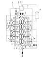
- FIG. 1 is an explanatory diagram schematically showing an example of the fuel cell system of the present embodiment.
- the fuel cell system includes a power generation means 10, a switching means 20, a fuel gas supply means 31, an oxidant gas supply means 32, a load detection means 40, and a control means 50.
- the power generation means 10 includes five solid oxide fuel cells 11A to 11E and fuel gas supply paths 13 and five fuel cells 12A to 12E connected in series to all the fuel electrodes 12A to 12E of the five solid oxide fuel cells.
- an oxidant gas supply path 15 for connecting all the air electrodes 14A to 14E of the solid oxide fuel cells 11A to 11E in series.
- the fuel gas supply path 13 and the oxidant gas supply path 15 have circulation paths 16 and 17, respectively.
- the solid oxide fuel cells 11A to 11E, the fuel gas supply path 13, the oxidant gas supply path 15, and the circulation paths 16 and 17 are disposed inside the heat insulating means 60 made of a heat insulating material. ing.
- these five solid oxide fuel cells 11A to 11E employ a so-called fuel cell stack in which unit fuel cells (not shown) are connected in series. As can be seen from FIG.
- connection terminals 18A to 18E and 19A to 19E can be electrically connected in parallel via connection terminals 18A to 18E and 19A to 19E.
- the switching means 20 switches the electrical connection state between the connection terminals 18A to 18E, 19A to 19E and, for example, the connection means 110 of the external load (motor) 100.
- a so-called switch is used.
- the connection means 110 employs a circuit including an inverter (not shown).
- the fuel gas supply means 31 supplies fuel gas to the fuel gas supply path 13, and in this example, is constituted by fuel pumps 31A and 31B and a flow rate regulator 31C.
- the oxidant gas supply means 32 supplies oxidant gas to the oxidant gas supply path 15, and in this example, is constituted by an air blower 32A and a flow rate regulator 32B.
- the load detection means 40 detects the load of the external load (motor) 100, and an accelerator opening sensor is applied in this example. Further, the control means 50 outputs to the switching means 20, the fuel gas supply means 31, and the oxidant gas supply means 32 in response to an input from the load detection means 40.
- the control means 50 stores the number of fuel cells connected to be described later, the power generation output with respect to the voltage (or current density) between the terminals, the data of the relationship map of the power generation efficiency and the heat dissipation amount, and values preset from these data, It is possible to apply a control device that outputs in response to the above.
- the fuel cell system of this example includes a fuel reformer 70 upstream of the fuel gas supply path 13. The fuel reformer 70 can generate reformed fuel from the air supplied by the air blower 71 and the fuel and water supplied by the fuel pumps 31A and 31B and the flow rate regulator 31C.
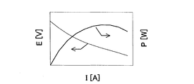
- each fuel cell exhibits current (I) -voltage (V) characteristics and current (I) -power generation output (P) characteristics as shown in FIG.
- V current
- I current
- P power generation output
- FIG. 3 shows a relationship map of the number of connected fuel cells, the fuel cell voltage (inter-terminal voltage), and the gross power generation output (output not including power consumption such as auxiliary devices) in this example.
- the gross power generation output has a peak with respect to the voltage of the fuel cell (corresponding to the voltage of the fuel cell system because of the parallel connection in this example). The higher the voltage than the peak, the lower the gross power output, and the lower the voltage from the peak, the lower the gross power output.
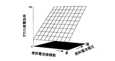
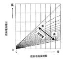
- 4A and 4B are a plan view and a three-dimensional view showing a relationship map of the number of connected fuel cells, fuel cell voltage, and gross power generation efficiency (efficiency not including power consumption such as auxiliary devices) in this example. . As shown in the figure, regardless of the number of connected fuel cells, the higher the voltage, the higher the gross power generation efficiency.
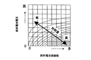
- FIG. 5 shows a relationship map of the number of fuel cells connected in this example, the fuel cell voltage (terminal voltage), and the amount of heat released from all fuel cells.
- the smaller the number of fuel cells connected the lower the heat radiation amount, and the larger the number of fuel cell connections, the higher the heat radiation amount.
- the higher the voltage of the fuel cell corresponding to the voltage of the fuel cell system because it is connected in parallel
- the lower the amount of heat dissipation the higher the voltage of the fuel cell, the higher the amount of heat dissipation.
- the number of fuel cells connected and the voltage of the fuel cell are controlled.
- the gross power generation efficiency on the thick line in FIG. 6B and the heat radiation amount on the thick line in FIG. 6C can be achieved.
- gross power generation efficiency is basically improved when a low power generation output request is input.
- the gross power generation efficiency improves as the number of connected fuel cells increases.
- the amount of heat released from the fuel cell decreases.
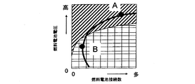
- the hatched portions in FIGS. 6A, 6B, and 6C indicate regions where the amount of heat released from the fuel cell is below the amount of heat that maintains the heat balance of the fuel cell system.
- the conventional fuel cell system requires additional fuel to be burned by the combustor, and the overall efficiency has deteriorated.
- the fuel cell system of this example for example, by reducing the number of connected fuel cells and operating at point B instead of point A on the thick line, the heat radiation amount is improved while satisfying the gross power generation output requirement. Can be made.
- standby can be performed with high efficiency without consuming excess fuel, so that necessary power can be generated according to the external load.
- fuel combustion that does not directly contribute to power generation can be suppressed, and the overall efficiency of the combined power generation and heat dissipation can be improved.
- the gross power generation efficiency on the thick line in FIG. 7B and the heat radiation amount on the thick line in FIG. 7C can be achieved.
- the gross power generation efficiency can be increased by increasing the number of connected fuel cells and operating the system (for example, when operating at point A).
- the amount of heat radiation can be improved while satisfying the gross power generation output requirement. Can do.
- FIG. 8 is a flowchart showing the operation of the fuel cell system.
- Step 1 (abbreviated as “S1” in the figure. The same applies hereinafter) proceeds to Step 2 when an output change command is input from the outside to the control means by a power generation output request input or a heat request input.
- Step 2 calculates and selects the operating point, that is, the number of connected fuel cells with reference to the fuel cell operation maps shown in FIGS. At this time, the operating point can be set while avoiding the operating point at the shaded portion in FIG. 6A, FIG. 6B, and FIG. 6C.
- the above control corresponds to selecting operating points such as point A and point B in FIGS. 6A, 6B, 6C, 7A, 7B, and 7C.
- Step 3 switches the switch to control the number of connected fuel cells so as to realize the set operating point, and controls the fuel gas supply means and the oxidant gas supply means to control the fuel gas flow rate and the air flow rate. Control. The operation control is performed in this way, and a transition is made to steady operation.
- the values on the horizontal axis of the operation maps of FIGS. 3 to 5 can be used as the number of connected fuel cells.
- the fuel gas flow rate and the air flow rate are the relationship map of the number of fuel cell connections, fuel cell voltage, and gross power generation output in FIG. 3, and the number of fuel cell connections, fuel cell voltage, and gross power generation efficiency in FIGS. 4A and 4B. A preset value can be used according to the relationship map.
- FIG. 9 is an explanatory diagram schematically showing another example of the fuel cell system of the present embodiment.
- the fuel cell system includes a power generation means 10, a switching means 20, a fuel gas supply means 31, an oxidant gas supply means 32, a load detection means 40, and a control means 50. It is a thing.
- the power generation means 10 includes five solid oxide fuel cells 11A to 11E and fuel gas supply paths 13 and five fuel cells 12A to 12E connected in series to all the fuel electrodes 12A to 12E of the five solid oxide fuel cells.
- an oxidant gas supply path 15 for connecting all the air electrodes 14A to 14E of the solid oxide fuel cells 11A to 11E in series.
- the fuel gas supply path 13 and the oxidant gas supply path 15 have circulation paths 16 and 17, respectively.
- the solid oxide fuel cells 11A to 11E, the fuel gas supply passage 13, the oxidant gas passage 15, and the circulation passages 16 and 17 are disposed inside the heat insulating means 60 made of a heat insulating material. Yes.
- these five solid oxide fuel cells 11A to 11E employ a so-called fuel cell stack in which unit fuel cells (not shown) are connected in series. As can be seen from FIG.
- these solid oxide fuel cells 11A to 11E can be electrically connected in series via connection terminals 18A to 18E and 19A to 19E.
- the switching means 20 switches the electrical connection state between the connection terminals 18A to 18E, 19A to 19E and, for example, the connection means 110 of the external load (motor) 100. In this example, a so-called switch is used. Applicable.
- the connection means 110 employs a circuit including an inverter (not shown).
- the fuel gas supply means 31 supplies fuel gas to the fuel gas supply path 13, and in this example, is constituted by fuel pumps 31A and 31B and a flow rate regulator 31C.
- the oxidant gas supply means 32 supplies oxidant gas to the oxidant gas supply path 15, and in this example, is constituted by an air blower 32A and a flow rate regulator 32B.
- the load detection means 40 detects the load of the external load (motor) 100, and an accelerator opening sensor is applied in this example.
- the control means 50 outputs to the switching means 20, the fuel gas supply means 31, and the oxidant gas supply means 32 in response to an input from the load detection means 40.
- the control means 50 stores the number of fuel cell connections (to be described later), gross power generation output with respect to the fuel cell voltage (terminal voltage), data on the relationship map of gross power generation efficiency and heat dissipation, and values preset from these.
- a control device that outputs in response to an input can be applied.
- the fuel cell system of this example includes a fuel reformer 70 upstream of the fuel gas supply path 13.
- the fuel reformer 70 can generate reformed fuel from the air supplied by the air blower 71 and the fuel and water supplied by the fuel pumps 31A and 31B and the flow rate regulator 31C.
- the map which shows the relationship between the number of fuel cell connection of this example, a fuel cell voltage, and gross power generation output (output which does not consider power consumption, such as auxiliary equipment) is shown in FIG.
- the gross power generation output has a peak with respect to the fuel cell voltage. The higher the fuel cell voltage from the peak, the lower the gross power output, and the lower the fuel cell voltage from the peak, the lower the gross power output.
- FIG. 11 shows a map showing the relationship between the number of connected fuel cells, the fuel cell voltage, and the gross power generation efficiency (efficiency without taking into account power consumption such as auxiliary devices) in this example. As shown in the figure, the gross power generation efficiency increases as the number of fuel cell connections increases, and the gross power generation efficiency increases as the fuel cell voltage increases.
- FIG. a map showing the relationship between the number of connected fuel cells, the fuel cell voltage, and the amount of heat released from all the fuel cells in this example is shown in FIG.
- the smaller the number of fuel cells connected the higher the heat radiation amount, and the larger the number of fuel cell connections, the lower the heat radiation amount.
- the lower the fuel cell voltage the higher the heat dissipation amount.
- the higher the fuel cell voltage the lower the heat dissipation amount.
- step 1 proceeds to step 2 when an output change command is input from the outside to the control means by power generation output request input or heat request input.
- Step 2 refers to the fuel cell operation map FIGS. 10 to 12, calculates and selects the operation point, that is, the number of connected fuel cells, and proceeds to Step 3.
- the above selection is equivalent to selecting operating points such as point A and point B in FIGS. 6A, 6B, 6C, 7A, 7B, and 7C.
- Step 3 switches the switch to control the number of connected fuel cells so as to realize the set operating point, and controls the fuel gas supply means and the oxidant gas supply means to control the fuel gas flow rate and the air flow rate. Control. The operation control is performed in this way, and a transition is made to steady operation. Note that the values on the horizontal axis of the operation maps of FIGS. 10 to 12 can be used as the number of connected fuel cells.
- the fuel gas flow rate and the air flow rate correspond to the relationship map of the number of fuel cell connections, the fuel cell voltage and the gross power generation output in FIG. 10, and the relationship map of the number of fuel cell connections, the fuel cell voltage and the gross power generation efficiency in FIG. Thus, a preset value can be used.
- each fuel cell in the first embodiment can be replaced with five fuel cells in the second embodiment, and each fuel cell in the second embodiment can be replaced with that in the first embodiment. It is possible to replace it with five fuel cells.
- Electric power generation means 11A, 11B, 11C, 11D, 11E Solid oxide fuel cell 12A, 12B, 12C, 12D, 12E Fuel electrode 13 Fuel gas supply path 14A, 14B, 14C, 14D, 14E Air electrode 15 Oxidant gas supply Route 16, 17 Circulation path 18A, 18B, 18C, 18D, 18E, 19A, 19B, 19C, 19D, 19E Connection terminal 20 Switching means 31 Fuel gas supply means 31A, 31B Fuel pump 31C, 32B Flow rate regulator 32 Oxidant gas Supply means 32A, 71 Air blower 40 Load detection means (accelerator opening sensor) 50 control means 60 heat insulation means (heat insulation material) 70 Fuel reformer 100 External load (motor) 110 Connection means
Abstract
Description
その結果、複数の燃料電池の燃料極等を直列に接続する燃料ガス供給路を有する構成とすること等により、上記目的が達成できることを見出し、本発明を完成するに至った。 The inventors of the present invention have made extensive studies to achieve the above object.
As a result, the inventors have found that the above object can be achieved by, for example, a configuration having a fuel gas supply path for connecting the fuel electrodes of a plurality of fuel cells in series, and the present invention has been completed.
本実施形態の燃料電池システムは、発電手段と、切替手段と、燃料ガス供給手段と、酸化剤ガス供給手段と、負荷検知手段と、制御手段とを備えたものである。
そして、前記発電手段は、複数の燃料電池と、複数の燃料電池の全部又は一部の燃料極を直列に接続する燃料ガス供給路及び複数の燃料電池の全部又は一部の空気極を直列に接続する酸化剤ガス供給路を有する。また、これら複数の燃料電池は、接続端子を介して電気的に直列及び並列のいずれか一方又は双方に接続可能なものである。
また、前記切替手段は、接続端子と外部負荷の接続手段との電気的な接続状態を切り替えるものである。
更に、前記燃料ガス供給手段は、燃料ガス供給路に燃料ガスを供給するものであり、更に前記酸化剤ガス供給手段は、酸化剤ガス供給路に酸化剤ガスを供給するものである。
また、前記負荷検知手段は、外部負荷の負荷を検知するものである。
更に又、前記制御手段は、予め取得してある燃料電池接続数に対応する全体発電出力曲線と運転温度領域との関係から、負荷検知手段からの入力に応じて、切替手段、燃料ガス供給手段、酸化剤ガス供給手段を制御するものである。 Hereinafter, a fuel cell system according to an embodiment of the present invention will be described in detail.
The fuel cell system according to the present embodiment includes a power generation means, a switching means, a fuel gas supply means, an oxidant gas supply means, a load detection means, and a control means.
The power generation means includes a plurality of fuel cells, a fuel gas supply path that connects all or some of the fuel electrodes of the plurality of fuel cells in series, and all or some of the air electrodes of the plurality of fuel cells in series. It has an oxidant gas supply path for connection. The plurality of fuel cells can be electrically connected to either one or both of series and parallel via a connection terminal.
The switching means switches the electrical connection state between the connection terminal and the connection means of the external load.
The fuel gas supply means supplies fuel gas to the fuel gas supply path, and the oxidant gas supply means supplies oxidant gas to the oxidant gas supply path.
The load detection means detects a load of an external load.
Furthermore, the control means includes a switching means, a fuel gas supply means according to an input from the load detection means based on the relationship between the total power generation output curve corresponding to the number of fuel cell connections acquired in advance and the operating temperature region. The oxidant gas supply means is controlled.
つまり、複数の燃料電池の少なくとも一部の燃料極を直列に接続する燃料ガス供給路及び複数の燃料電池の少なくとも一部の空気極を直列に接続する酸化剤ガス供給路を有する構成とすることにより、上流側の燃料電池から下流側の燃料電池に高温ガスが流れることとなる。
例えば、下流側の燃料電池の接続端子と外部負荷の接続手段との電気的な接続状態を、切替手段によって切断し、下流側の燃料電池の発電を停止させる場合を考える。
このとき、下流側の燃料電池の温度は、上流側の燃料電池の出口温度に漸近する。
実際には、放熱による温度低下が生じるため、同じ温度にはならないが、燃料電池や燃料ガス供給路、酸化剤ガス供給路などの配設状態を適宜設定することによって、温度低下を抑制することができ、切替手段により再接続したときに発電に問題のないレベルとなる。
そして、このように下流側の燃料電池が発電を停止した状態で、燃料ガス供給路に燃料ガスを存在させ、且つ酸化剤ガス供給路に酸化剤ガスを存在させると、この燃料電池を待機状態、すなわち開回路(OCV)状態に保持することができる。
これにより、高温状態である燃料電池において、燃料極が酸化されることや空気極が還元されることを回避できる。なお、このような下流側の燃料電池は発電していないため、下流側の燃料電池内において、燃料ガスや酸化剤ガスが減少することはない。
なお、燃料電池とは、単独で発電可能な単位燃料電池セルを1つ以上組み合わせたものであり、燃料電池単セルのみならず、燃料電池スタックをも含む意味に解釈されなければならない。
したがって、燃料電池においては、単位燃料電池セルが直列に組み合わさった場合、燃料電池の各単位燃料電池セルに流れる電流は一定になる。また、燃料電池においては、単位燃料電池セルが並列に組み合わさった場合、燃料電池の各単位燃料電池セルの端子間電圧は一定になる。 Such a fuel cell system is capable of standby with high efficiency without consuming excess fuel, so that it is possible to generate necessary power according to an external load.
In other words, the fuel gas supply path that connects at least some of the fuel electrodes of the plurality of fuel cells in series and the oxidant gas supply path that connects at least some of the air electrodes of the plurality of fuel cells in series. As a result, the high-temperature gas flows from the upstream fuel cell to the downstream fuel cell.
For example, consider a case where the electrical connection state between the connection terminal of the downstream fuel cell and the connection means of the external load is disconnected by the switching means, and the power generation of the downstream fuel cell is stopped.
At this time, the temperature of the downstream fuel cell gradually approaches the outlet temperature of the upstream fuel cell.
In practice, the temperature drops due to heat dissipation, so the temperature does not become the same, but the temperature drop is suppressed by appropriately setting the arrangement of the fuel cell, fuel gas supply path, oxidant gas supply path, etc. When the power is reconnected by the switching means, the power generation level is satisfactory.
When the fuel gas is present in the fuel gas supply path and the oxidant gas is present in the oxidant gas supply path in a state where the power generation of the downstream fuel cell is stopped in this manner, the fuel cell is put into a standby state. That is, it can be held in an open circuit (OCV) state.
Thereby, in the fuel cell in a high temperature state, it is possible to avoid the oxidation of the fuel electrode and the reduction of the air electrode. In addition, since such a downstream fuel cell does not generate electric power, the fuel gas and the oxidant gas do not decrease in the downstream fuel cell.
The fuel cell is a combination of one or more unit fuel cells that can generate electricity alone, and should be interpreted to include not only a single fuel cell but also a fuel cell stack.
Therefore, in the fuel cell, when the unit fuel cells are combined in series, the current flowing through each unit fuel cell of the fuel cell is constant. Further, in the fuel cell, when unit fuel cells are combined in parallel, the terminal voltage of each unit fuel cell of the fuel cell becomes constant.
このような燃料電池システムは、余分な燃料を消費することなく高効率な待機が可能になるため、外部負荷に応じて、必要な電力を発電することが可能になるだけでなく、最上流の燃料電池を常に発電状態にする必要がなくなる。したがって、いずれかの燃料電池を発電状態にしておけば、循環路でつながれた他の燃料電池を待機状態にすることができ、例えば、燃料電池の劣化などの状況に応じて、燃料電池を選択することができる。更に、ガス加熱のための燃焼器や熱交換器などを取り去り小型化することが可能になるという利点もある。 In the fuel cell system of this embodiment, it is desirable that both the fuel gas supply path and the oxidant gas supply path have a circulation path.
Since such a fuel cell system enables high-efficiency standby without consuming excess fuel, it is possible not only to generate necessary power according to the external load, but also to the most upstream. The fuel cell need not always be in a power generation state. Therefore, if one of the fuel cells is in a power generation state, another fuel cell connected by a circulation path can be put into a standby state. For example, the fuel cell is selected according to the situation such as deterioration of the fuel cell. can do. Furthermore, there is an advantage that it is possible to reduce the size by removing the combustor or the heat exchanger for heating the gas.
このような燃料電池システムは、余分な燃料を消費することなく高効率な待機が可能になるため、外部負荷に応じて、必要な電力を発電することが可能になるだけでなく、発電状態や待機状態にある各燃料電池の温度を一定に保つことができる。特に、全燃料電池が一括に断熱手段の内部に配設されることによって、各燃料電池の性能や劣化のばらつきをより抑制することができる。 Furthermore, in the fuel cell system of the present embodiment, it is desirable that a plurality of fuel cells, a fuel gas supply path, and an oxidant gas supply path are disposed inside the heat insulating means.
Since such a fuel cell system enables highly efficient standby without consuming extra fuel, it is possible not only to generate necessary power according to the external load, but also to the power generation state and The temperature of each fuel cell in the standby state can be kept constant. In particular, since all the fuel cells are collectively disposed inside the heat insulating means, variations in performance and deterioration of each fuel cell can be further suppressed.
このような燃料電池システムは、余分な燃料を消費することなく高効率な待機が可能になるため、外部負荷に応じて、必要な電力を発電することが可能になるだけでなく、外部からの発電出力要求入力や熱要求入力に応じて、最適なシステムの運転状態を選択することができる。 In the fuel cell system of the present embodiment, it is desirable that the control means further outputs to the switching means in response to an external power generation output request input or heat request input.
Since such a fuel cell system enables high-efficiency standby without consuming excess fuel, it is possible not only to generate necessary power according to the external load, but also from the outside. An optimal system operating state can be selected according to the power generation output request input and the heat request input.
このような燃料電池システムは、余分な燃料を消費することなく高効率な待機が可能になるため、外部負荷に応じて、必要な電力を発電することが可能になる。更に、システムの運転状態の変更時における過渡変動に影響されない制御目標を持つことが可能になり、システムの運転状態の変更を円滑に行うことができる。 Further, in the fuel cell system of the present embodiment, the control means outputs the switching means according to the external power generation output request input or the heat request input, based on the operation map for each number of connected fuel cells. It is desirable to control the number of connected fuel cells.
Such a fuel cell system is capable of standby with high efficiency without consuming excess fuel, so that it is possible to generate necessary power according to an external load. Furthermore, it becomes possible to have a control target that is not affected by transient fluctuations when the operating state of the system is changed, and the operating state of the system can be changed smoothly.
ここで、「低発電出力要求」とは、かかる発電出力要求に応じて各燃料電池が発電しつづけたときに、燃料電池システムの熱バランスが発電可能な温度を維持できないような発電出力の要求をいう。
このような燃料電池システムは、余分な燃料を消費することなく高効率な待機が可能になるため、外部負荷に応じて、必要な電力を発電することが可能になる。更に、システムの運転状態の変更時における過渡変動に影響されない制御目標を持つことが可能になり、システムの運転状態の変更を円滑に行うことができる。更にまた、発電に直接寄与しない燃料燃焼を抑制して、発電量と放熱量とを合わせた全体としての効率を向上させることができる。
つまり、低出力時は、基本的には発電効率が向上する。そして、燃料電池の数が多くなるほど、発電効率は向上する。これに伴い、燃料電池からの放熱量は低下する。したがって、発電出力要求がある一定値以下となった場合、燃料電池からの放熱量が、システムの熱バランスを維持するための熱量を下回る可能性が生じる。このような場合でも、燃料電池の接続数を削減し、燃料電池からの放熱量を増加させることによって、燃料を燃焼器などで燃焼させることなどを回避することができる。 Further, in the fuel cell system of the present embodiment, for example, when the control means outputs to the switching means in response to an external low power generation output request input, the fuel is based on the operation map for each number of connected fuel cells. It is desirable to reduce the number of battery connections.
Here, “low power generation output request” means a request for power generation output such that when each fuel cell continues to generate power in response to the power generation output request, the heat balance of the fuel cell system cannot maintain the temperature at which it can generate power. Say.
Such a fuel cell system is capable of standby with high efficiency without consuming excess fuel, so that it is possible to generate necessary power according to an external load. Furthermore, it becomes possible to have a control target that is not affected by transient fluctuations when the operating state of the system is changed, and the operating state of the system can be changed smoothly. Furthermore, fuel combustion that does not directly contribute to power generation can be suppressed, and the overall efficiency of the combined power generation and heat dissipation can be improved.
In other words, the power generation efficiency is basically improved at low output. And the power generation efficiency improves as the number of fuel cells increases. Along with this, the amount of heat released from the fuel cell decreases. Therefore, when the power generation output request falls below a certain value, there is a possibility that the amount of heat released from the fuel cell will be less than the amount of heat for maintaining the heat balance of the system. Even in such a case, it is possible to avoid burning the fuel with a combustor or the like by reducing the number of connected fuel cells and increasing the heat radiation from the fuel cell.
ここで、「高熱要求」とは、発電手段の燃料電池や燃料ガス供給手段、酸化剤ガス供給手段などから、自然に放熱される放熱量を超える放熱量の要求をいう。
このような燃料電池システムは、余分な燃料を消費することなく高効率な待機が可能になるため、外部負荷に応じて、必要な電力を発電することが可能になる。更に、システムの運転状態の変更時における過渡変動に影響されない制御目標を持つことが可能になり、システムの運転状態の変更を円滑に行うことができる。更にまた、外部からの熱要求が多い状況下において、発電量と放熱量とを合わせた全体としての効率を向上させることが可能となる。 Furthermore, in the fuel cell system of the present embodiment, for example, when the control means outputs to the switching means in response to an external high heat request input, the fuel cell system is based on the operation map for each number of connected fuel cells. It is desirable to reduce the number of connections.
Here, the “high heat requirement” refers to a request for a heat dissipation amount that exceeds the heat dissipation amount naturally radiated from the fuel cell of the power generation means, the fuel gas supply means, the oxidant gas supply means, and the like.
Such a fuel cell system is capable of standby with high efficiency without consuming excess fuel, so that it is possible to generate necessary power according to an external load. Furthermore, it becomes possible to have a control target that is not affected by transient fluctuations when the operating state of the system is changed, and the operating state of the system can be changed smoothly. Furthermore, under a situation where there is a large amount of heat demand from the outside, it is possible to improve the overall efficiency of the combined power generation and heat dissipation.
ここで、本実施形態に係る燃料電池システムの一例について図面を参照しながら詳細に説明する。
図1は、本実施形態の燃料電池システムの一例を概略的に示す説明図である。同図に示すように、この燃料電池システムは、発電手段10と、切替手段20と、燃料ガス供給手段31及び酸化剤ガス供給手段32と、負荷検知手段40と、制御手段50とを備えたものである。
そして、前記発電手段10は、5つの固体酸化物形燃料電池11A~11Eと、5つの固体酸化物形燃料電池の全部の燃料極12A~12Eを直列に接続する燃料ガス供給路13及び5つの固体酸化物形燃料電池11A~11Eの全部の空気極14A~14Eを直列に接続する酸化剤ガス供給路15とを有している。
なお、本例において、燃料ガス供給路13及び酸化剤ガス供給路15は、それぞれ循環路16、17を有している。
また、本例において、固体酸化物形燃料電池11A~11E、燃料ガス供給路13及び酸化剤ガス供給路15、更に循環路16、17は、断熱材からなる断熱手段60の内部に配設されている。
更に、本例において、これら5つの固体酸化物形燃料電池11A~11Eは、図示しない単位燃料電池セルを直列に接続した、いわゆる燃料電池スタックを適用している。
図1より知れる様に、これら固体酸化物形燃料電池11A~11Eは、接続端子18A~18E、19A~19Eを介して電気的に並列に接続可能なものとなっている。
また、前記切替手段20は、接続端子18A~18E、19A~19Eと例えば外部負荷(モーター)100の接続手段110との電気的な接続状態を切り替えるものであり、本例においては、いわゆるスイッチを適用している。なお、接続手段110は、図示しないインバータを備えた回路を適用している。
更に、前記燃料ガス供給手段31は、燃料ガス供給路13に燃料ガスを供給するものであり、本例においては、燃料ポンプ31A、31B及び流量調整器31Cにより構成されている。また、前記酸化剤ガス供給手段32は、酸化剤ガス供給路15に酸化剤ガスを供給するものであり、本例においては、空気ブロワ32A及び流量調整器32Bにより構成されている。
また、前記負荷検知手段40は、外部負荷(モーター)100の負荷を検知するものであり、本例においては、アクセル開度センサを適用している。
更に、前記制御手段50は、負荷検知手段40からの入力に応じて、切替手段20、燃料ガス供給手段31、酸化剤ガス供給手段32に出力するものである。なお、該制御手段50は、後述する燃料電池接続数、端子間電圧(又は電流密度)に対する発電出力、発電効率及び放熱量の関係マップのデータやこれらから予め設定される値を格納し、入力に応じて出力する制御装置を適用することができる。
また、本例の燃料電池システムにおいては、燃料ガス供給路13の上流に燃料改質器70を備えている。該燃料改質器70は、空気ブロワ71により供給される空気と、燃料ポンプ31A、31B及び流量調整器31Cにより供給される燃料や水とから改質燃料を生成することができる。 (First embodiment)
Here, an example of the fuel cell system according to the present embodiment will be described in detail with reference to the drawings.
FIG. 1 is an explanatory diagram schematically showing an example of the fuel cell system of the present embodiment. As shown in the figure, the fuel cell system includes a power generation means 10, a switching means 20, a fuel gas supply means 31, an oxidant gas supply means 32, a load detection means 40, and a control means 50. Is.
The power generation means 10 includes five solid
In this example, the fuel
In this example, the solid
Further, in this example, these five solid
As can be seen from FIG. 1, these solid
The switching means 20 switches the electrical connection state between the
Further, the fuel gas supply means 31 supplies fuel gas to the fuel
The load detection means 40 detects the load of the external load (motor) 100, and an accelerator opening sensor is applied in this example.
Further, the control means 50 outputs to the switching means 20, the fuel gas supply means 31, and the oxidant gas supply means 32 in response to an input from the load detection means 40. The control means 50 stores the number of fuel cells connected to be described later, the power generation output with respect to the voltage (or current density) between the terminals, the data of the relationship map of the power generation efficiency and the heat dissipation amount, and values preset from these data, It is possible to apply a control device that outputs in response to the above.
Further, the fuel cell system of this example includes a
同図に示すように、各燃料電池は、電流値が高くなると、電圧値が低くなる。また、各燃料電池は、電流値がある値であるときに、最大発電出力値を示す。 In this example, each fuel cell exhibits current (I) -voltage (V) characteristics and current (I) -power generation output (P) characteristics as shown in FIG.
As shown in the figure, the voltage value of each fuel cell decreases as the current value increases. Each fuel cell shows a maximum power generation output value when the current value is a certain value.
同図に示すように、燃料電池の接続数が少ないほどグロス発電出力が低くなり、燃料電池の接続数が多いほどグロス発電出力が高くなる。また、同じ接続数で見た場合、グロス発電出力は、燃料電池の電圧(本例では並列接続であるため燃料電池システムの電圧に相当)に対してピークを持っている。ピークより電圧が高いほど、グロス発電出力が低くなり、ピークより電圧を低くすると、グロス発電出力も低くなる。 Here, FIG. 3 shows a relationship map of the number of connected fuel cells, the fuel cell voltage (inter-terminal voltage), and the gross power generation output (output not including power consumption such as auxiliary devices) in this example.
As shown in the figure, the smaller the number of fuel cells connected, the lower the gross power generation output, and the larger the number of fuel cells connected, the higher the gross power generation output. Further, when viewed with the same number of connections, the gross power generation output has a peak with respect to the voltage of the fuel cell (corresponding to the voltage of the fuel cell system because of the parallel connection in this example). The higher the voltage than the peak, the lower the gross power output, and the lower the voltage from the peak, the lower the gross power output.
同図に示すように、燃料電池の接続数にかかわらず、電圧が高いほど、グロス発電効率が高くなる。 4A and 4B are a plan view and a three-dimensional view showing a relationship map of the number of connected fuel cells, fuel cell voltage, and gross power generation efficiency (efficiency not including power consumption such as auxiliary devices) in this example. .
As shown in the figure, regardless of the number of connected fuel cells, the higher the voltage, the higher the gross power generation efficiency.
同図に示すように、燃料電池の接続数が少ないほど放熱量が低くなり、燃料電池の接続数が多いほど放熱量が高くなる。また、燃料電池の電圧(並列接続であるため燃料電池システムの電圧に相当)が高いほど、放熱量が低くなり、燃料電池の電圧が低くなるにつれて、放熱量が高くなる。 Further, FIG. 5 shows a relationship map of the number of fuel cells connected in this example, the fuel cell voltage (terminal voltage), and the amount of heat released from all fuel cells.
As shown in the figure, the smaller the number of fuel cells connected, the lower the heat radiation amount, and the larger the number of fuel cell connections, the higher the heat radiation amount. Further, the higher the voltage of the fuel cell (corresponding to the voltage of the fuel cell system because it is connected in parallel), the lower the amount of heat dissipation, and the higher the voltage of the fuel cell, the higher the amount of heat dissipation.
但し、低発電出力要求入力のときは、基本的にグロス発電効率が向上する。特に、燃料電池の接続数が多くなるほど、グロス発電効率が向上する。これに伴い、燃料電池からの放熱量が低下する。
図6A, 図6B及び図6Cにおける斜線部は、燃料電池からの放熱量が、燃料電池システムの熱バランスを維持する熱量を下回る領域を示している。この領域においては、従来の燃料電池システムにおいては、追加燃料を燃焼器で燃焼させることを要し、全体としての効率が悪化していた。
一方、本例の燃料電池システムにおいては、例えば燃料電池の接続数を削減して太線上のA点ではなく、B点で運転することにより、グロス発電出力要求を満足したまま、放熱量を向上させることができる。
このように、本例の燃料電池システムにおいては、余分な燃料を消費することなく高効率な待機が可能になるため、外部負荷に応じて、必要な電力を発電することが可能になる。また、システムの運転状態の変更時における過渡変動に影響されない制御目標を持つことが可能になり、システムの運転状態の変更を円滑に行うことができる。更に、発電に直接寄与しない燃料燃焼を抑制して、発電量と放熱量とを合わせた全体としての効率を向上させることができる。 Here, in the fuel cell system of this example, when there is an external gross power generation output request input (for example, the value on the thick line in FIG. 6A), the number of fuel cells connected and the voltage of the fuel cell are controlled. The gross power generation efficiency on the thick line in FIG. 6B and the heat radiation amount on the thick line in FIG. 6C can be achieved.
However, gross power generation efficiency is basically improved when a low power generation output request is input. In particular, the gross power generation efficiency improves as the number of connected fuel cells increases. Along with this, the amount of heat released from the fuel cell decreases.
The hatched portions in FIGS. 6A, 6B, and 6C indicate regions where the amount of heat released from the fuel cell is below the amount of heat that maintains the heat balance of the fuel cell system. In this region, the conventional fuel cell system requires additional fuel to be burned by the combustor, and the overall efficiency has deteriorated.
On the other hand, in the fuel cell system of this example, for example, by reducing the number of connected fuel cells and operating at point B instead of point A on the thick line, the heat radiation amount is improved while satisfying the gross power generation output requirement. Can be made.
In this way, in the fuel cell system of this example, standby can be performed with high efficiency without consuming excess fuel, so that necessary power can be generated according to the external load. In addition, it is possible to have a control target that is not affected by transient fluctuations when the operating state of the system is changed, and the operating state of the system can be changed smoothly. Furthermore, fuel combustion that does not directly contribute to power generation can be suppressed, and the overall efficiency of the combined power generation and heat dissipation can be improved.
低熱要求入力のときは、燃料電池の接続数を増やして、システムを運転することにより、グロス発電効率を高くすることができる(例えば、A点で運転する場合。)。
一方、高熱要求入力のときは、例えば燃料電池の接続数を削減して太線上のA点ではなく、B点で運転することにより、グロス発電出力要求を満足したまま、放熱量を向上させることができる。
このように、本例の燃料電池システムにおいては、余分な燃料を消費することなく高効率な待機が可能になるため、外部負荷に応じて、必要な電力を発電することが可能になる。また、システムの運転状態の変更時における過渡変動に影響されない制御目標を持つことが可能になり、システムの運転状態の変更を円滑に行うことができる。更に、発電に直接寄与しない燃料燃焼を抑制して、発電量と放熱量とを合わせた全体としての効率を向上させることができる。 Further, in the fuel cell system of this example, when there is a gross power generation output request input from the outside (for example, the value on the thick line in FIG. 7A), by controlling the number of fuel cell connections and the fuel cell voltage, The gross power generation efficiency on the thick line in FIG. 7B and the heat radiation amount on the thick line in FIG. 7C can be achieved.
At the time of low heat request input, the gross power generation efficiency can be increased by increasing the number of connected fuel cells and operating the system (for example, when operating at point A).
On the other hand, at the time of high heat demand input, for example, by reducing the number of connected fuel cells and operating at point B instead of point A on the thick line, the amount of heat radiation can be improved while satisfying the gross power generation output requirement. Can do.
In this way, in the fuel cell system of this example, standby can be performed with high efficiency without consuming excess fuel, so that necessary power can be generated according to the external load. In addition, it is possible to have a control target that is not affected by transient fluctuations when the operating state of the system is changed, and the operating state of the system can be changed smoothly. Furthermore, fuel combustion that does not directly contribute to power generation can be suppressed, and the overall efficiency of the combined power generation and heat dissipation can be improved.
なお、燃料電池の接続数は図3~図5の運転マップの横軸の値を用いることができる。また、燃料ガス流量及び空気流量は、図3の燃料電池接続数、燃料電池電圧、及びグロス発電出力の関係マップ、及び図4A, 図4Bの燃料電池接続数、燃料電池電圧、及びグロス発電効率の関係マップに応じて、予め設定された値を用いることができる。 Step 3 switches the switch to control the number of connected fuel cells so as to realize the set operating point, and controls the fuel gas supply means and the oxidant gas supply means to control the fuel gas flow rate and the air flow rate. Control. The operation control is performed in this way, and a transition is made to steady operation.
Note that the values on the horizontal axis of the operation maps of FIGS. 3 to 5 can be used as the number of connected fuel cells. In addition, the fuel gas flow rate and the air flow rate are the relationship map of the number of fuel cell connections, fuel cell voltage, and gross power generation output in FIG. 3, and the number of fuel cell connections, fuel cell voltage, and gross power generation efficiency in FIGS. 4A and 4B. A preset value can be used according to the relationship map.
次に、本実施形態に係る燃料電池システムの他の例について図面を参照しながら詳細に説明する。
図9は、本実施形態の燃料電池システムの他の例を概略的に示す説明図である。同図に示すように、この燃料電池システムは、発電手段10と、切替手段20と、燃料ガス供給手段31と、酸化剤ガス供給手段32と、負荷検知手段40と、制御手段50とを備えたものである。
そして、この発電手段10は、5つの固体酸化物形燃料電池11A~11Eと、5つの固体酸化物形燃料電池の全部の燃料極12A~12Eを直列に接続する燃料ガス供給路13及び5つの固体酸化物形燃料電池11A~11Eの全部の空気極14A~14Eを直列に接続する酸化剤ガス供給路15とを有している。
なお、本例において、燃料ガス供給路13及び酸化剤ガス供給路15は、それぞれ循環路16、17を有している。
また、本例において、固体酸化物形燃料電池11A~11E、燃料ガス供給路13、酸化剤ガス通路15、更に循環路16、17は、断熱材からなる断熱手段60の内部に配設されている。
更に、本例において、これら5つの固体酸化物形燃料電池11A~11Eは、図示しない単位燃料電池セルを直列に接続した、いわゆる燃料電池スタックを適用している。
図9より知れる様に、これら固体酸化物形燃料電池11A~11Eは、接続端子18A~18E、19A~19Eを介して電気的に直列に接続可能なものとなっている。
また、前記切替手段20は、接続端子18A~18E、19A~19Eと例えば外部負荷(モーター)100の接続手段110との電気的な接続状態を切り替えるものであり、本例においては、いわゆるスイッチを適用している。なお、接続手段110は、図示しないインバータを備えた回路を適用している。
更に、前記燃料ガス供給手段31は、燃料ガス供給路13に燃料ガスを供給するものであり、本例においては、燃料ポンプ31A、31B及び流量調整器31Cにより構成されている。また、前記酸化剤ガス供給手段32は、酸化剤ガス供給路15に酸化剤ガスを供給するものであり、本例においては、空気ブロワ32A及び流量調整器32Bにより構成されている。
また、前記負荷検知手段40は、外部負荷(モーター)100の負荷を検知するものであり、本例においては、アクセル開度センサを適用している。
更に、前記制御手段50は、負荷検知手段40からの入力に応じて、切替手段20、燃料ガス供給手段31、酸化剤ガス供給手段32に出力するものである。なお、該制御手段50は、後述する燃料電池接続数、燃料電池電圧(端子間電圧)に対するグロス発電出力、グロス発電効率及び放熱量の関係マップのデータやこれらから予め設定される値を格納し、入力に応じて出力する制御装置を適用することができる。
また、本例の燃料電池システムにおいては、燃料ガス供給路13の上流に燃料改質器70を備えている。該燃料改質器70は、空気ブロワ71により供給される空気と、燃料ポンプ31A、31B及び流量調整器31Cにより供給される燃料や水とから改質燃料を生成することができる。 (Second Embodiment)
Next, another example of the fuel cell system according to the present embodiment will be described in detail with reference to the drawings.
FIG. 9 is an explanatory diagram schematically showing another example of the fuel cell system of the present embodiment. As shown in the figure, the fuel cell system includes a power generation means 10, a switching means 20, a fuel gas supply means 31, an oxidant gas supply means 32, a load detection means 40, and a control means 50. It is a thing.
The power generation means 10 includes five solid
In this example, the fuel
In this example, the solid
Further, in this example, these five solid
As can be seen from FIG. 9, these solid
The switching means 20 switches the electrical connection state between the
Further, the fuel gas supply means 31 supplies fuel gas to the fuel
The load detection means 40 detects the load of the external load (motor) 100, and an accelerator opening sensor is applied in this example.
Further, the control means 50 outputs to the switching means 20, the fuel gas supply means 31, and the oxidant gas supply means 32 in response to an input from the load detection means 40. The control means 50 stores the number of fuel cell connections (to be described later), gross power generation output with respect to the fuel cell voltage (terminal voltage), data on the relationship map of gross power generation efficiency and heat dissipation, and values preset from these. A control device that outputs in response to an input can be applied.
Further, the fuel cell system of this example includes a
同図に示すように、燃料電池の接続数が少ないほどグロス発電出力が低くなり、燃料電池の接続数が多いほどグロス発電出力が高くなる。また、同じ接続数で見た場合、グロス発電出力は、燃料電池電圧に対してピークを持っている。ピークより燃料電池電圧が高いほど、グロス発電出力が低くなり、ピークより燃料電池電圧を低くすると、グロス発電出力も低くなる。 Here, the map which shows the relationship between the number of fuel cell connection of this example, a fuel cell voltage, and gross power generation output (output which does not consider power consumption, such as auxiliary equipment) is shown in FIG.
As shown in the figure, the smaller the number of fuel cells connected, the lower the gross power generation output, and the larger the number of fuel cells connected, the higher the gross power generation output. Further, when viewed with the same number of connections, the gross power generation output has a peak with respect to the fuel cell voltage. The higher the fuel cell voltage from the peak, the lower the gross power output, and the lower the fuel cell voltage from the peak, the lower the gross power output.
同図に示すように、燃料電池の接続数が多いほどグロス発電効率が高くなり、燃料電池電圧が高いほどグロス発電効率が高くなる。 FIG. 11 shows a map showing the relationship between the number of connected fuel cells, the fuel cell voltage, and the gross power generation efficiency (efficiency without taking into account power consumption such as auxiliary devices) in this example.
As shown in the figure, the gross power generation efficiency increases as the number of fuel cell connections increases, and the gross power generation efficiency increases as the fuel cell voltage increases.
同図に示すように、燃料電池の接続数が少ないほど放熱量が高くなり、燃料電池の接続数が多いほど放熱量が低くなる。また、燃料電池電圧が低いほど放熱量が高くなり、燃料電池電圧が高くなるにつれて、放熱量が低くなる。 Furthermore, a map showing the relationship between the number of connected fuel cells, the fuel cell voltage, and the amount of heat released from all the fuel cells in this example is shown in FIG.
As shown in the figure, the smaller the number of fuel cells connected, the higher the heat radiation amount, and the larger the number of fuel cell connections, the lower the heat radiation amount. In addition, the lower the fuel cell voltage, the higher the heat dissipation amount. The higher the fuel cell voltage, the lower the heat dissipation amount.
なお、燃料電池の接続数は図10~図12の運転マップの横軸の値を用いることができる。また、燃料ガス流量及び空気流量は、図10の燃料電池接続数、燃料電池電圧及びグロス発電出力の関係マップ、及び図11の燃料電池接続数、燃料電池電圧及びグロス発電効率の関係マップに応じて、予め設定された値を用いることができる。 Step 3 switches the switch to control the number of connected fuel cells so as to realize the set operating point, and controls the fuel gas supply means and the oxidant gas supply means to control the fuel gas flow rate and the air flow rate. Control. The operation control is performed in this way, and a transition is made to steady operation.
Note that the values on the horizontal axis of the operation maps of FIGS. 10 to 12 can be used as the number of connected fuel cells. The fuel gas flow rate and the air flow rate correspond to the relationship map of the number of fuel cell connections, the fuel cell voltage and the gross power generation output in FIG. 10, and the relationship map of the number of fuel cell connections, the fuel cell voltage and the gross power generation efficiency in FIG. Thus, a preset value can be used.
例えば、第1の実施形態の各燃料電池をそれぞれ第2の実施形態の5つ燃料電池に置き換えることも可能であり、また、第2の実施形態の各燃料電池をそれぞれ第1の実施形態の5つの燃料電池に置き換えることも可能である。 In the above embodiment, only the case where the fuel cells can be connected in parallel (first embodiment) and the case where the fuel cells can be connected in series (second embodiment) have been described. However, the fuel cells are connected in parallel. Needless to say, the present invention can also be applied to cases where connection is possible in a combination of series.
For example, each fuel cell in the first embodiment can be replaced with five fuel cells in the second embodiment, and each fuel cell in the second embodiment can be replaced with that in the first embodiment. It is possible to replace it with five fuel cells.
11A、11B、11C、11D、11E 固体酸化物形燃料電池
12A、12B、12C、12D、12E 燃料極
13 燃料ガス供給路
14A、14B、14C、14D、14E 空気極
15 酸化剤ガス供給路
16、17 循環路
18A、18B、18C、18D、18E、19A、19B、19C、19D、19E 接続端子
20 切替手段
31 燃料ガス供給手段
31A、31B 燃料ポンプ
31C、32B 流量調整器
32 酸化剤ガス供給手段
32A、71 空気ブロワ
40 負荷検知手段(アクセル開度センサ)
50 制御手段
60 断熱手段(断熱材)
70 燃料改質器
100 外部負荷(モーター)
110 接続手段
DESCRIPTION OF
50 control means 60 heat insulation means (heat insulation material)
70
110 Connection means
Claims (5)
- 接続端子を介して電気的に直列及び/又は並列に接続可能な複数の燃料電池と、該複数の燃料電池の全部又は一部の燃料極を直列に接続する燃料ガス供給路及び該複数の燃料電池の全部又は一部の空気極を直列に接続する酸化剤ガス供給路を有する発電手段と、
上記接続端子と外部負荷の接続手段との電気的な接続状態を切り替える切替手段と、
上記燃料ガス供給路に燃料ガスを供給する燃料ガス供給手段及び上記酸化剤ガス供給路に酸化剤ガスを供給する酸化剤ガス供給手段と、
上記外部負荷の負荷を検知する負荷検知手段と、
予め取得してある燃料電池接続数に対応する全体発電出力曲線と運転温度領域との関係から、上記負荷検知手段からの入力に応じて、運転温度領域の中で出力曲線を選択し、かつ燃料電池の電圧値が最も高くなる燃料電池接続数を選択して上記切替手段、上記燃料ガス供給手段及び上記酸化剤ガス供給手段に出力する制御手段と、
を備えたことを特徴とする燃料電池システム。 A plurality of fuel cells that can be electrically connected in series and / or in parallel via a connection terminal, a fuel gas supply path for connecting all or some of the fuel electrodes of the plurality of fuel cells in series, and the plurality of fuels A power generation means having an oxidant gas supply path for connecting all or part of the air electrodes of the battery in series;
Switching means for switching the electrical connection state between the connection terminal and the external load connection means;
Fuel gas supply means for supplying fuel gas to the fuel gas supply path and oxidant gas supply means for supplying oxidant gas to the oxidant gas supply path;
Load detecting means for detecting the load of the external load;
Based on the relationship between the total power generation output curve corresponding to the number of fuel cell connections acquired in advance and the operating temperature range, an output curve is selected in the operating temperature range according to the input from the load detection means, and the fuel A control means for selecting the number of fuel cell connections where the voltage value of the battery is highest and outputting it to the switching means, the fuel gas supply means and the oxidant gas supply means;
A fuel cell system comprising: - 上記燃料ガス供給路及び上記酸化剤ガス供給路の少なくとも一方が、循環路を有することを特徴とする請求項1に記載の燃料電池システム。 2. The fuel cell system according to claim 1, wherein at least one of the fuel gas supply path and the oxidant gas supply path has a circulation path.
- 上記複数の燃料電池と上記燃料ガス供給路及び上記酸化剤ガス供給路とが、断熱手段の内部に配設されていることを特徴とする請求項1又は2に記載の燃料電池システム。 The fuel cell system according to claim 1 or 2, wherein the plurality of fuel cells, the fuel gas supply path, and the oxidant gas supply path are disposed inside a heat insulating means.
- 上記制御手段が、外部からの発電出力要求入力又は熱要求入力に応じて、上記切替手段に出力することを特徴とする請求項1~3のいずれか1つの項に記載の燃料電池システム。 The fuel cell system according to any one of claims 1 to 3, wherein the control means outputs to the switching means in response to an external power generation output request input or heat request input.
- 接続端子を介して電気的に直列及び/又は並列に接続可能な複数の燃料電池と、該複数の燃料電池の全部又は一部の燃料極を直列に接続する燃料ガス供給路及び該複数の燃料電池の全部又は一部の空気極を直列に接続する酸化剤ガス供給路を有する発電手段と、上記接続端子と外部負荷の接続手段との電気的な接続状態を切り替える切替手段と、上記燃料ガス供給路に燃料ガスを供給する燃料ガス供給手段及び上記酸化剤ガス供給路に酸化剤ガスを供給する酸化剤ガス供給手段と、上記外部負荷の負荷を検知する負荷検知手段と、更に、制御手段から成る燃料電池システムを制御する方法であって、該方法が下記の制御手段の動作に基づく:
予め取得してある燃料電池接続数に対応する全体発電出力曲線と運転温度領域との関係から、上記負荷検知手段からの入力に応じて、運転温度領域の中で出力曲線を選択し、かつ燃料電池の電圧値が最も高くなる燃料電池接続数を選択して、上記切替手段、上記燃料ガス供給手段及び上記酸化剤ガス供給手段を制御する。 A plurality of fuel cells that can be electrically connected in series and / or in parallel via a connection terminal, a fuel gas supply path for connecting all or some of the fuel electrodes of the plurality of fuel cells in series, and the plurality of fuels A power generation means having an oxidant gas supply path for connecting all or some of the air electrodes of the battery in series; a switching means for switching an electrical connection state between the connection terminal and the connection means of the external load; and the fuel gas Fuel gas supply means for supplying fuel gas to the supply path, oxidant gas supply means for supplying oxidant gas to the oxidant gas supply path, load detection means for detecting the load of the external load, and control means A method of controlling a fuel cell system comprising: the method is based on the operation of the following control means:
Based on the relationship between the total power generation output curve corresponding to the number of fuel cell connections acquired in advance and the operating temperature range, an output curve is selected in the operating temperature range according to the input from the load detection means, and the fuel The number of fuel cell connections with the highest voltage value of the battery is selected to control the switching means, the fuel gas supply means, and the oxidant gas supply means.
Priority Applications (4)
| Application Number | Priority Date | Filing Date | Title |
|---|---|---|---|
| CN201080022196.4A CN102439774B (en) | 2009-05-20 | 2010-04-15 | Fuel cell system and method for controlling same |
| JP2011514366A JP5257516B2 (en) | 2009-05-20 | 2010-04-15 | Fuel cell system and control method thereof |
| US13/264,241 US9048474B2 (en) | 2009-05-20 | 2010-04-15 | Fuel cell system and method for controlling same |
| EP10777636.1A EP2434569B1 (en) | 2009-05-20 | 2010-04-15 | Fuel cell system and method for controlling same |
Applications Claiming Priority (2)
| Application Number | Priority Date | Filing Date | Title |
|---|---|---|---|
| JP2009-121680 | 2009-05-20 | ||
| JP2009121680 | 2009-05-20 |
Publications (1)
| Publication Number | Publication Date |
|---|---|
| WO2010134401A1 true WO2010134401A1 (en) | 2010-11-25 |
Family
ID=43126089
Family Applications (1)
| Application Number | Title | Priority Date | Filing Date |
|---|---|---|---|
| PCT/JP2010/056782 WO2010134401A1 (en) | 2009-05-20 | 2010-04-15 | Fuel cell system and method for controlling same |
Country Status (5)
| Country | Link |
|---|---|
| US (1) | US9048474B2 (en) |
| EP (1) | EP2434569B1 (en) |
| JP (1) | JP5257516B2 (en) |
| CN (1) | CN102439774B (en) |
| WO (1) | WO2010134401A1 (en) |
Cited By (6)
| Publication number | Priority date | Publication date | Assignee | Title |
|---|---|---|---|---|
| JP2016134287A (en) * | 2015-01-19 | 2016-07-25 | 東京瓦斯株式会社 | Fuel battery system, operation method for the same and configuration method for the same |
| WO2019103388A1 (en) * | 2017-11-24 | 2019-05-31 | (주)두산 모빌리티 이노베이션 | Fuel cell power pack and power supply control method thereof |
| JP2019526150A (en) * | 2016-11-30 | 2019-09-12 | シーアールアールシー チンタオ シーファン カンパニー,リミティッド | Fuel cell control method, apparatus and system, and railway vehicle |
| US11145883B2 (en) | 2018-08-24 | 2021-10-12 | Toyota Jidosha Kabushiki Kaisha | Fuel cell system |
| WO2022014914A1 (en) * | 2020-07-17 | 2022-01-20 | (주)두산 모빌리티 이노베이션 | System and method for activating fuel cell |
| US11462758B2 (en) | 2018-08-24 | 2022-10-04 | Toyota Jidosha Kabushiki Kaisha | Fuel cell system |
Families Citing this family (1)
| Publication number | Priority date | Publication date | Assignee | Title |
|---|---|---|---|---|
| JP6488112B2 (en) * | 2014-11-19 | 2019-03-20 | 東京瓦斯株式会社 | Fuel cell system |
Citations (6)
| Publication number | Priority date | Publication date | Assignee | Title |
|---|---|---|---|---|
| JP2002358991A (en) * | 2001-03-28 | 2002-12-13 | Mitsubishi Heavy Ind Ltd | Operating method of fuel cell power generation system and fuel cell power generation system |
| JP2004079537A (en) * | 2002-08-16 | 2004-03-11 | Hewlett-Packard Development Co Lp | Fuel cell device |
| JP2004311112A (en) * | 2003-04-03 | 2004-11-04 | Toyota Motor Corp | Fuel cell system, vehicle with fuel cell system, and method for controlling fuel cell system |
| JP2006107819A (en) * | 2004-10-01 | 2006-04-20 | Nitto Denko Corp | Power source device |
| JP2007509470A (en) | 2003-10-21 | 2007-04-12 | アルバータ リサーチ カウンシル インコーポレイテッド | Operation control of solid oxide fuel cells |
| JP2007242266A (en) * | 2006-03-06 | 2007-09-20 | Canon Inc | Fuel cell device, and operation method of fuel cell |
Family Cites Families (3)
| Publication number | Priority date | Publication date | Assignee | Title |
|---|---|---|---|---|
| JP4742501B2 (en) * | 2004-02-17 | 2011-08-10 | 日産自動車株式会社 | Fuel cell system |
| JP4984543B2 (en) * | 2005-07-21 | 2012-07-25 | 日産自動車株式会社 | Fuel cell system |
| JP5040042B2 (en) * | 2005-11-24 | 2012-10-03 | トヨタ自動車株式会社 | Fuel cell |
-
2010
- 2010-04-15 US US13/264,241 patent/US9048474B2/en not_active Expired - Fee Related
- 2010-04-15 JP JP2011514366A patent/JP5257516B2/en not_active Expired - Fee Related
- 2010-04-15 WO PCT/JP2010/056782 patent/WO2010134401A1/en active Application Filing
- 2010-04-15 EP EP10777636.1A patent/EP2434569B1/en not_active Not-in-force
- 2010-04-15 CN CN201080022196.4A patent/CN102439774B/en not_active Expired - Fee Related
Patent Citations (6)
| Publication number | Priority date | Publication date | Assignee | Title |
|---|---|---|---|---|
| JP2002358991A (en) * | 2001-03-28 | 2002-12-13 | Mitsubishi Heavy Ind Ltd | Operating method of fuel cell power generation system and fuel cell power generation system |
| JP2004079537A (en) * | 2002-08-16 | 2004-03-11 | Hewlett-Packard Development Co Lp | Fuel cell device |
| JP2004311112A (en) * | 2003-04-03 | 2004-11-04 | Toyota Motor Corp | Fuel cell system, vehicle with fuel cell system, and method for controlling fuel cell system |
| JP2007509470A (en) | 2003-10-21 | 2007-04-12 | アルバータ リサーチ カウンシル インコーポレイテッド | Operation control of solid oxide fuel cells |
| JP2006107819A (en) * | 2004-10-01 | 2006-04-20 | Nitto Denko Corp | Power source device |
| JP2007242266A (en) * | 2006-03-06 | 2007-09-20 | Canon Inc | Fuel cell device, and operation method of fuel cell |
Non-Patent Citations (1)
| Title |
|---|
| See also references of EP2434569A4 * |
Cited By (10)
| Publication number | Priority date | Publication date | Assignee | Title |
|---|---|---|---|---|
| JP2016134287A (en) * | 2015-01-19 | 2016-07-25 | 東京瓦斯株式会社 | Fuel battery system, operation method for the same and configuration method for the same |
| JP2019526150A (en) * | 2016-11-30 | 2019-09-12 | シーアールアールシー チンタオ シーファン カンパニー,リミティッド | Fuel cell control method, apparatus and system, and railway vehicle |
| WO2019103388A1 (en) * | 2017-11-24 | 2019-05-31 | (주)두산 모빌리티 이노베이션 | Fuel cell power pack and power supply control method thereof |
| KR20190060417A (en) * | 2017-11-24 | 2019-06-03 | (주)두산 모빌리티 이노베이션 | Fuel cell power pack, and power supply control method thereof |
| KR102038201B1 (en) * | 2017-11-24 | 2019-10-29 | (주)두산 모빌리티 이노베이션 | Fuel cell power pack, and power supply control method thereof |
| US11145883B2 (en) | 2018-08-24 | 2021-10-12 | Toyota Jidosha Kabushiki Kaisha | Fuel cell system |
| US11462758B2 (en) | 2018-08-24 | 2022-10-04 | Toyota Jidosha Kabushiki Kaisha | Fuel cell system |
| WO2022014914A1 (en) * | 2020-07-17 | 2022-01-20 | (주)두산 모빌리티 이노베이션 | System and method for activating fuel cell |
| KR20220010258A (en) * | 2020-07-17 | 2022-01-25 | (주)두산 모빌리티 이노베이션 | Fuel cell activation system and method |
| KR102424731B1 (en) * | 2020-07-17 | 2022-07-25 | (주)두산 모빌리티 이노베이션 | Fuel cell activation system and method |
Also Published As
| Publication number | Publication date |
|---|---|
| JPWO2010134401A1 (en) | 2012-11-08 |
| US20120040265A1 (en) | 2012-02-16 |
| EP2434569A1 (en) | 2012-03-28 |
| CN102439774B (en) | 2014-03-12 |
| EP2434569A4 (en) | 2014-12-31 |
| US9048474B2 (en) | 2015-06-02 |
| JP5257516B2 (en) | 2013-08-07 |
| EP2434569B1 (en) | 2016-01-27 |
| CN102439774A (en) | 2012-05-02 |
Similar Documents
| Publication | Publication Date | Title |
|---|---|---|
| JP5257516B2 (en) | Fuel cell system and control method thereof | |
| KR101133698B1 (en) | Air-cooled fuel cell system | |
| US6444338B1 (en) | Fuel cell system with improved startability | |
| JP2006294621A (en) | Method and device for controlled solid oxide fuel cell (sofc)/turbine hybrid power generation | |
| JP5643194B2 (en) | Fuel cell system and method for stabilizing fuel cell power supply | |
| JP2011165636A (en) | Parallel fuel cell power system | |
| US20090102291A1 (en) | Fuel-Cell Based Power Generating System Having Power Conditioning Apparatus | |
| JP6475023B2 (en) | FUEL CELL SYSTEM, ITS OPERATION METHOD, AND ITS CONFIGURATION METHOD | |
| JP4934950B2 (en) | Fuel cell power generator and operation control method | |
| JP2009158463A (en) | Fuel cell power generation system | |
| JP2009193921A (en) | Fuel cell stack and fuel cell system | |
| CA2414226A1 (en) | Method for regulating the operation of fuel cell installations controlled according to heat and/or power requirement | |
| JP2010067354A (en) | Fuel cell system | |
| JP6520252B2 (en) | Fuel cell system | |
| KR101510066B1 (en) | Fuel cell assembly and method of control | |
| JP2006318808A (en) | Fuel cell system | |
| JP6643938B2 (en) | Distributed power generation system | |
| JP6492874B2 (en) | Fuel cell system | |
| JP2016110967A (en) | Fuel cell system | |
| JP2016134258A (en) | Control device for fuel battery system | |
| JP6183334B2 (en) | Fuel cell system and fuel cell control method | |
| JP6847184B2 (en) | Combined heat and power system | |
| US20220320535A1 (en) | Fuel cell power systems | |
| JP6643939B2 (en) | Combined heat and power system | |
| CN117480700A (en) | Fuel cell power system |
Legal Events
| Date | Code | Title | Description |
|---|---|---|---|
| WWE | Wipo information: entry into national phase |
Ref document number: 201080022196.4 Country of ref document: CN |
|
| 121 | Ep: the epo has been informed by wipo that ep was designated in this application |
Ref document number: 10777636 Country of ref document: EP Kind code of ref document: A1 |
|
| WWE | Wipo information: entry into national phase |
Ref document number: 2011514366 Country of ref document: JP |
|
| WWE | Wipo information: entry into national phase |
Ref document number: 13264241 Country of ref document: US |
|
| NENP | Non-entry into the national phase |
Ref country code: DE |
|
| WWE | Wipo information: entry into national phase |
Ref document number: 2010777636 Country of ref document: EP |