WO2010125832A1 - タギングmr画像における撮像対象の運動解析方法及びmri装置 - Google Patents
タギングmr画像における撮像対象の運動解析方法及びmri装置 Download PDFInfo
- Publication number
- WO2010125832A1 WO2010125832A1 PCT/JP2010/050173 JP2010050173W WO2010125832A1 WO 2010125832 A1 WO2010125832 A1 WO 2010125832A1 JP 2010050173 W JP2010050173 W JP 2010050173W WO 2010125832 A1 WO2010125832 A1 WO 2010125832A1
- Authority
- WO
- WIPO (PCT)
- Prior art keywords
- pixel
- imaging target
- series
- motion
- sequence
- Prior art date
- Legal status (The legal status is an assumption and is not a legal conclusion. Google has not performed a legal analysis and makes no representation as to the accuracy of the status listed.)
- Ceased
Links
- 0 C*C(*)C(*)(CCC1)CC1(CC*(CCC[C@](C)(CCCCCCCCC1)I)C[C@]1I)[U] Chemical compound C*C(*)C(*)(CCC1)CC1(CC*(CCC[C@](C)(CCCCCCCCC1)I)C[C@]1I)[U] 0.000 description 2
Images










Classifications
-
- A—HUMAN NECESSITIES
- A61—MEDICAL OR VETERINARY SCIENCE; HYGIENE
- A61B—DIAGNOSIS; SURGERY; IDENTIFICATION
- A61B5/00—Measuring for diagnostic purposes; Identification of persons
- A61B5/05—Detecting, measuring or recording for diagnosis by means of electric currents or magnetic fields; Measuring using microwaves or radio waves
- A61B5/055—Detecting, measuring or recording for diagnosis by means of electric currents or magnetic fields; Measuring using microwaves or radio waves involving electronic [EMR] or nuclear [NMR] magnetic resonance, e.g. magnetic resonance imaging
-
- A—HUMAN NECESSITIES
- A61—MEDICAL OR VETERINARY SCIENCE; HYGIENE
- A61B—DIAGNOSIS; SURGERY; IDENTIFICATION
- A61B5/00—Measuring for diagnostic purposes; Identification of persons
- A61B5/103—Measuring devices for testing the shape, pattern, colour, size or movement of the body or parts thereof, for diagnostic purposes
- A61B5/11—Measuring movement of the entire body or parts thereof, e.g. head or hand tremor or mobility of a limb
- A61B5/1107—Measuring contraction of parts of the body, e.g. organ or muscle
-
- G—PHYSICS
- G01—MEASURING; TESTING
- G01R—MEASURING ELECTRIC VARIABLES; MEASURING MAGNETIC VARIABLES
- G01R33/00—Arrangements or instruments for measuring magnetic variables
- G01R33/20—Arrangements or instruments for measuring magnetic variables involving magnetic resonance
- G01R33/44—Arrangements or instruments for measuring magnetic variables involving magnetic resonance using nuclear magnetic resonance [NMR]
- G01R33/48—NMR imaging systems
- G01R33/54—Signal processing systems, e.g. using pulse sequences ; Generation or control of pulse sequences; Operator console
- G01R33/56—Image enhancement or correction, e.g. subtraction or averaging techniques, e.g. improvement of signal-to-noise ratio and resolution
- G01R33/563—Image enhancement or correction, e.g. subtraction or averaging techniques, e.g. improvement of signal-to-noise ratio and resolution of moving material, e.g. flow contrast angiography
- G01R33/56308—Characterization of motion or flow; Dynamic imaging
- G01R33/56325—Cine imaging
-
- G—PHYSICS
- G01—MEASURING; TESTING
- G01R—MEASURING ELECTRIC VARIABLES; MEASURING MAGNETIC VARIABLES
- G01R33/00—Arrangements or instruments for measuring magnetic variables
- G01R33/20—Arrangements or instruments for measuring magnetic variables involving magnetic resonance
- G01R33/44—Arrangements or instruments for measuring magnetic variables involving magnetic resonance using nuclear magnetic resonance [NMR]
- G01R33/48—NMR imaging systems
- G01R33/54—Signal processing systems, e.g. using pulse sequences ; Generation or control of pulse sequences; Operator console
- G01R33/56—Image enhancement or correction, e.g. subtraction or averaging techniques, e.g. improvement of signal-to-noise ratio and resolution
- G01R33/563—Image enhancement or correction, e.g. subtraction or averaging techniques, e.g. improvement of signal-to-noise ratio and resolution of moving material, e.g. flow contrast angiography
- G01R33/56308—Characterization of motion or flow; Dynamic imaging
- G01R33/56333—Involving spatial modulation of the magnetization within an imaged region, e.g. spatial modulation of magnetization [SPAMM] tagging
-
- G—PHYSICS
- G06—COMPUTING OR CALCULATING; COUNTING
- G06T—IMAGE DATA PROCESSING OR GENERATION, IN GENERAL
- G06T7/00—Image analysis
- G06T7/20—Analysis of motion
- G06T7/246—Analysis of motion using feature-based methods, e.g. the tracking of corners or segments
-
- G—PHYSICS
- G01—MEASURING; TESTING
- G01R—MEASURING ELECTRIC VARIABLES; MEASURING MAGNETIC VARIABLES
- G01R33/00—Arrangements or instruments for measuring magnetic variables
- G01R33/20—Arrangements or instruments for measuring magnetic variables involving magnetic resonance
- G01R33/44—Arrangements or instruments for measuring magnetic variables involving magnetic resonance using nuclear magnetic resonance [NMR]
- G01R33/48—NMR imaging systems
- G01R33/54—Signal processing systems, e.g. using pulse sequences ; Generation or control of pulse sequences; Operator console
- G01R33/56—Image enhancement or correction, e.g. subtraction or averaging techniques, e.g. improvement of signal-to-noise ratio and resolution
- G01R33/561—Image enhancement or correction, e.g. subtraction or averaging techniques, e.g. improvement of signal-to-noise ratio and resolution by reduction of the scanning time, i.e. fast acquiring systems, e.g. using echo-planar pulse sequences
- G01R33/5613—Generating steady state signals, e.g. low flip angle sequences [FLASH]
-
- G—PHYSICS
- G06—COMPUTING OR CALCULATING; COUNTING
- G06T—IMAGE DATA PROCESSING OR GENERATION, IN GENERAL
- G06T2207/00—Indexing scheme for image analysis or image enhancement
- G06T2207/10—Image acquisition modality
- G06T2207/10072—Tomographic images
- G06T2207/10088—Magnetic resonance imaging [MRI]
-
- G—PHYSICS
- G06—COMPUTING OR CALCULATING; COUNTING
- G06T—IMAGE DATA PROCESSING OR GENERATION, IN GENERAL
- G06T2207/00—Indexing scheme for image analysis or image enhancement
- G06T2207/30—Subject of image; Context of image processing
- G06T2207/30004—Biomedical image processing
- G06T2207/30048—Heart; Cardiac
Definitions
- the present invention relates to a motion analysis method and an MRI apparatus for an imaging target in a tagging MR image.
- a tagging MRI method that magnetically labels human tissue is often used.
- the tagging MRI method it is possible to analyze the three-dimensional motion of the heart wall by analyzing time-series tagging MR images (time-series MR images (cine MRI)).
- Non-Patent Document 2 proposes a method using a gabor filter bank. This method uses the spatial expansion of the tag, and is effective in analyzing the global movement of the tissue. However, there is a problem that an analysis error tends to occur in the local tag movement analysis.
- An object of the present invention is to provide a technique for enabling a motion of an imaging target to be analyzed in a tagging MR image based on an idea different from that for extracting a tag by image processing.
- the present invention is a motion analysis method of an imaging target in a tagging MR image, and cine imaging is performed N L times (N L is a positive integer of 2 or more) with different tag patterns for the same motion of the imaging target. It is a step of obtaining N L pieces tagging MR image of the sequence the imaging time for a plurality of time phases in the movement of the imaging target, N L for the same pixel in the N L-number of tagged MR images of each time phase The pixel value series having the length N L for the pixel and the pixel value series in different time phases are detected in the time series different from each other, thereby detecting the pixels constituting the same code series.
- each of the tag patterns is a pattern formed so that the pixel value series constitutes a predetermined code series.
- the time phase means a phase in the motion of the imaging target
- the motion to be imaged includes a plurality of time phases (phases).
- phases For example, when the same movement is cine imaged multiple times by causing the imaging target to repeat movements such as movement and deformation a plurality of times, the same time phase (movement) is obtained in a plurality of cine images obtained by multiple cine imaging. Those in phase) indicate the same state (position, shape, etc.) of the imaging target.
- those in different time phases (motion phases) may show different states (position, shape, etc.) depending on the motion of the imaging target.
- the pixel includes not only a two-dimensional pixel but also a three-dimensional voxel.
- the pixel value may be a luminance value signal or a phase value signal.
- a ratio occupied by each of a plurality of code sequences mixed in each pixel is calculated based on the pixel value series, and based on the ratio, less than one pixel size. It is preferable to calculate the momentum of the imaging target. In this case, the motion can be analyzed with a size less than one pixel.
- the present invention is a motion analysis method of an imaging target in a tagging MR image, and a plurality of time phases in the motion of the imaging target are obtained by performing cine imaging on the imaging target with a predetermined tag pattern. obtaining a tagged MR images of time-series captured, the respective pixel values of pixels of the N L-number contained in tagged MR images of each time phase (N L is a positive integer of 2 or more), the N L pieces
- the time series tagging MR is detected by detecting a region in which the pixel value series constitutes the same code series in a different time phase from the step of making the length N L pixel value series for the area consisting of the pixels of Analyzing the motion of the imaging target in the image, wherein the predetermined tag pattern is a pattern formed so that the pixel value series constitutes a predetermined code series.
- the predetermined tag pattern is a pattern formed so that the pixel value series constitutes a predetermined code series.
- the motion of the imaging target can be analyzed
- the code sequence is preferably excellent in noise resistance, for example, preferably an orthogonal code sequence, preferably a spreading code sequence, more preferably a PN sequence, , M series.
- the present invention viewed from still another viewpoint is an MRI apparatus capable of executing the above steps.
- FIG. 1 is an overall configuration diagram of an MRI apparatus. It is a flowchart which shows the process sequence in an MRI apparatus. It is a flowchart of cine imaging. It is a pulse sequence diagram for MRI imaging. It is explanatory drawing of the method of the multiple times of cine imaging. It is a flowchart of the motion analysis of an imaging target. It is a figure explaining how to generate a pixel value series from a plurality of cine imaging. It is a figure which shows the movement tracking of a pixel. It is a figure which shows a tag pattern. It is a figure which shows the example of allocation of the code series to a pixel. It is an image photograph which shows an experimental result.
- the MRI apparatus 1 can perform imaging by the position information encoding MRI method of the present invention. Since the position information encoding MRI method in the present embodiment uses a tagging MRI method that magnetically labels (tags) an imaging target (for example, a human tissue), the MRI apparatus 1 performs imaging by the tagging MRI method. It is comprised so that it can do. In addition, as a tag on which an imaging target is superimposed, a striped or grid-like tag in an arbitrary direction can be generated. In this embodiment, the motion of the heart wall is described as an example of the motion of the analysis target. However, the motion of the imaging target and the analysis target in the present invention is not limited to these.
- the MRI apparatus 1 transmits a RF pulse to an imaging object and receives a signal generated at the imaging object, and a magnetic field generator 2 for generating a static magnetic field and a gradient magnetic field.
- the MRI apparatus 1 includes an RF transmitter 4 for generating a predetermined RF pulse transmitted from the RF coil 3 and an RF receiver for processing a reception signal (MRI signal) received by the RF coil 3.
- the tag pulse sequence can be generated by a combination of an RF pulse generated by the RF transmitter 4 and transmitted from the RF coil 3 and a gradient magnetic field generated by the magnetic field generator 2.
- the MRI signal output from the RF receiver 5 is given to the computer 8 via the A / D converter 4.
- the computer 8 performs processing such as image processing and motion analysis described later based on the acquired MRI signal.
- the computer 8 gives necessary instructions to the RF transmitter 4 and the controller 6 to control them.
- the computer 8 includes a processing processor 9, a storage unit 10 having an internal storage device and / or an external storage device, and a display unit 11 including a display.
- a computer program for controlling the MRI apparatus 1, a computer program for motion analysis of an imaging target, and other necessary computer programs are installed in the storage unit 10, and these programs are executed by a processing processor. Thus, the processing described below is realized.
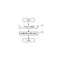
- FIG. 2 shows the procedure of the motion analysis processing of the imaging target (heart) of the MRI apparatus 1.
- the motion analysis process MRI apparatus 1, a plurality of times (N L times) cine imaging (moving imaging) capturing a step (step S1), the AND COMPUTER 8, N L pieces of cineMR obtained by imaging step It is roughly divided into an analysis processing step (step S2) for performing analysis processing of motion of the imaging target based on the image (time series MR image).
- step S1 The imaging process of step S1, the same movement of the same imaging target in the same imaging range, repeating the cine imaging N L times. These N L times of imaging are performed with different N L types of tag patterns. That is, in the imaging step of step S1, N L time-series tagging MR images (cine tagging MR images) showing the same movement of the imaging target but having different tag patterns in the image are obtained.
- the imaging process of step S1 is a loop for repeating one cine imaging (steps S12 to S15) until i becomes 1 to N L (N L times).
- the processing steps S11, S16, S17
- processing steps S12 to S15 for each cine imaging is provided in this loop.
- the computer 8 selects a tag pattern used for imaging (step S12).
- the storage unit 19 of the computer 8 stores N L types of tag patterns from the first tag pattern to the N L tag pattern, and the i-th tag in the i (i: 1 to N L ) th cine imaging. A pattern is selected. The details of the N L types of tag patterns will be described later.
- the computer 8 causes the transmitter 4 to generate an RF pulse that constitutes the i-th tagging sequence for the selected i-th tag pattern, transmits the RF pulse from the RF coil 3, and also generates a predetermined i-tagging sequence.
- generates a gradient magnetic field by the magnetic field generation part 2 is performed (step S13).
- the computer 8 executes a process for performing the i-th cine imaging (step S14).
- the time-series tagging MR image obtained by this cine imaging is stored in the storage unit 10 of the computer 8 (step S15).
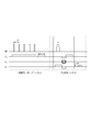
- FIG. 4 shows a pulse sequence when one cine imaging process (steps S12 to S15) is performed.
- This pulse sequence is a sequence by the FLASH method (FLASH sequence), and a DANTE tagging sequence for generating a selected tag pattern is added to the preparation portion of this FLASH sequence.
- the FLASH sequence in FIG. 4 is for capturing one still tagging MR image, and the FLASH sequence shown in the drawing is repeated M times per one cine imaging, and consists of M stationary tagging MR images. A series tagging MR image is obtained.
- a time series tagging MR image composed of M pieces of still tagging MR images is a time series tagging MR image corresponding to M time phases.
- a rectangular wave was used as the excitation RF pulse in the DANTE tagging sequence.
- the rectangular wave pulse interval t int in the DANTE tagging sequence may be set as appropriate, and the offset frequency f 0 or the phase offset may be set as appropriate in each RF pulse.
- the pulse intervals t int and G x are inversely proportional to the interval d int of the tag (a low-brightness marker portion in the image).
- the offset frequency f 0 or the phase offset of each RF pulse moves the center frequency position of the tag to an arbitrary position.
- N L types of tag patterns can be obtained.
- the MRI imaging sequence is not limited to the FLASH sequence, and the sequence for generating the tag pattern is not limited to the DANTE sequence.
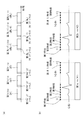
- FIG. 5A shows a pulse sequence when one cine imaging process (steps S12 to S15) as shown in FIG. 4 is performed N L times.
- the first tagging sequence to the NL tagging sequence in FIG. 5A correspond to the DANTE tagging sequence in FIG. 4, respectively.
- the first tagging sequence to the NL tagging sequence are for generating different tag patterns.
- the first cine (# 1) to the NL cine (#N L ) in FIG. 5A correspond to the FLASH sequence in FIG. 4, respectively, and the first cine imaging (# 1) to the Nth cine. This is for the L- th cine imaging (#N L ).
- Cine imaging each time (N L-th from the first time) (second 1cine (# 1) ⁇ a N L cine (#N L)), respectively, is to image the same motion of the imaging target. That is, when the imaging target is a heart, it is assumed that, for example, one cine imaging is performed during a time period corresponding to one heartbeat in a repeated heartbeat as illustrated in FIG. Each cine imaging is performed at the same timing (time phase) with respect to the cardiac cycle. As a result, in each cine imaging, the same motion of the heart is imaged. Therefore, in the time series tagging MR images of each time (from the first time to the NL time), the position and shape of the heart in the image are the same position and shape in the same time phase.
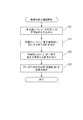
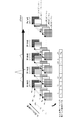
- the computer 8 performs the analysis processing of the motion of the imaging target based on the N L time-series tagging MR images obtained by the imaging step of step S1. Specifically, as shown in FIG. 6, first, the computer 8 converts the N L pixel values existing for each pixel of the tagging image into a pixel value series (length) of the length N L for the pixel. N L signal) is performed (step S21). Note that the pixel value here is a luminance value of the pixel, but may be a phase value of the pixel. As shown in FIG. 7, when N L time-series tagging MR images are arranged with the same time phase, N L tagging images are obtained for each time phase.
- N L pixel values for each pixel in each time phase, and these N L pixel values are arranged in the order of imaging, and the length N L is set.
- a pixel value series is assumed.
- the tag is present a low luminance region (black portion) and +1, the other region (the white part) regarded as -1, the pixel value sequence of length N L (signal length N L) is It can be considered that the pixel value is modulated by a code sequence of length N L. That is, a code sequence is assigned to each pixel in the first time phase. Therefore, when the imaging target does not move, the position of the pixel can be specified if the code sequence can be specified. Further, the tag is superimposed on the imaging target itself, and the tag moves as the imaging target moves.
- the computer 8 determines a code series corresponding to the pixel value series for each pixel by calculating a correlation function described later (step S22), and detects and tracks the positions of the pixels constituting the same code series between the respective time phases. By doing so (step S23), the movement of the tag can also be tracked. Therefore, the motion analysis of the imaging target can be performed without performing conventional image processing for tag position detection. Specifically, in each time phase, the position of the pixel having the same code sequence is stored in the storage unit 10, and the movement locus of the pixel having the same code sequence is displayed on the display unit 11. One user can accurately grasp the state of motion of the imaging target.
- the positional information (code sequence L 1 ) given to the pixel (x 1 , y 1 ) in the tag pattern in the initial time phase (first time phase) is changed by the movement of the imaging object. It is assumed that the pixel exists in the pixel (x 2 , y 2 ) in the M X time phase. In this case, the pixel (x 1 , y 1 ) in the initial time phase is the transmitting station that transmitted the code sequence L 1 , and the pixel (x 2 , y 2 ) in the M X time phase is transmitted from the transmitting station. It can be considered that the receiving station has received the code sequence L 1 .
- the receiving station can identify the code sequence indicated by the received signal by decoding the received signal (pixel value sequence). Accordingly, the tracking of the moving locus in the present embodiment is the same as detecting the receiving station (pixel) that has received the code sequence L 1 . Further, the tagging MR image, with the passage of time phase, since the tag contrast decreases, the pixel value sequence of the pixel in the M X time phase becomes a low SN ratio, it will be similar to poor communication environment. However, it is possible to cope with a decrease in tag contrast in a tagging MR image by selecting an appropriate code sequence as well as being able to cope with a poor communication environment by selecting an appropriate code sequence in communication. Can do.
- the low luminance area corresponding to the tag area is detected. Therefore, only the boundary of the tag area is the target of motion analysis. It was necessary to estimate the motion by interpolation. In order to estimate motion in detail using the conventional method, it is necessary to reduce both the tag area and the non-tag area. However, the relationship between the width of the tag area and the non-tag area and the pixel size, or between the two areas. Since the boundary is not an accurate rectangle, if the width of the tag area and the non-tag area is narrowed, the contrast between the two areas is lowered and detection becomes difficult.
- the position information is encoded for all pixels, and therefore, it is possible to analyze the motion at the pixel size for all the pixels. Therefore, detailed motion analysis is possible.
- a spread code is used as a code sequence, and spread spectrum (Spread Spectrum; SS).
- Spread spectrum is a communication method in which a narrowband modulated signal is modulated into a wideband signal having a spectrum several hundred to several thousand times by a spreading code and transmitted, and converted to the original narrowband signal on the receiving side and then demodulated.
- SS has the characteristics of being resistant to jamming and being resistant to poor transmission paths. In this way, by using the property of being strong against a transmission path with inferior spread spectrum, it is possible to perform a highly accurate motion analysis against a decrease in tag contrast due to the passage of time.
- PN sequence pseudo noise sequence
- the definition of PN sequence in a narrow sense is that the autocorrelation value is a periodic sequence in which only two levels are taken, and that the number of +1 and -1 in one cycle differs only by one. is there.
- the main PN sequence includes the M sequence. In the present embodiment, this M sequence is used as a code sequence. Note that the spread code sequence, the PN sequence, and the M sequence all have orthogonality in which codes are almost orthogonal, and are also orthogonal code sequences.
- a set of code sequences of length N L and number of sequences N s is L.
- the i-th code sequence of the code sequence set L is L i (1 ⁇ i ⁇ N s ), and each code element is l ij (1 ⁇ i ⁇ N s , 1 ⁇ j ⁇ N L ).
- l ij ⁇ ⁇ 1, -1 ⁇ .
- S (i) ⁇ S j (i) ⁇ (1 ⁇ j ⁇ N L ).
- the pixel value g (i) (x, y, p, j) of the obtained image is set as m j (i) , and considering the modulation using the MRI tagging method, It can be expressed as.
- k 1 is the pixel value contrast between the tag and the non-tag area
- k 2 corresponds to the pixel value in the non-tag area.
- k that minimizes ⁇ k indicates a code sequence used for modulation of the pixel. If the pixel having the smallest ⁇ k is traced from 1 to N L time phases, it is possible to track the movement of the pixel located at (x, y) in the initial time phase.
- Equation 6 is It becomes.
- k 3 corresponds to the contrast of the tag. Assuming that k 3 (x, y, j) is almost constant regardless of j, the correlation function ⁇ k is Thus, the code sequence corresponding to each pixel can be determined by obtaining k that minimizes ⁇ k.
- an M sequence is used as a code sequence.
- N L 7.
- a periodic tag pattern in which a tag region having a fixed length and a non-tag region having a fixed length are alternately repeated can be realized.
- a periodic tag pattern can be formed in all photographing.
- each horizontal column corresponds to one tag pattern.
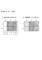
- Seven tag patterns (a part of the image (18 ⁇ 18 pixels) when the DANTE tagging sequence is designed so that “ ⁇ 1” in Table 1 is a high luminance region and “1” is a low luminance region corresponding to the tag.
- FIG. 9 shows an enlarged view of min).
- Each tag pattern in FIG. 9 is obtained when code sequences L 1 to L 6 are assigned to each pixel in the corresponding image area (18 ⁇ 18 pixels) as shown in FIG.
- the code sequences L 1 to L 6 assigned to each pixel indicate the position information of the pixel.
- the position information can be encoded without error up to about twice the longitudinal relaxation time T1 of the imaging target.
- the same code sequence is all assigned in the vertical direction. This is because all the tag patterns are vertically striped for simplification. However, it is natural that code sequences having different vertical directions in FIG. 10 may be assigned. In order to make the code sequences of adjacent pixels different in the horizontal direction and the vertical direction, it can be realized by mixing a plurality of tag patterns with horizontal stripes or grids. Such a tag pattern can also be generated by appropriately setting a tagging sequence.
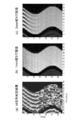
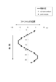
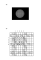
- FIG. 11B is a time-series image of a phantom that sine-moves in the left-right direction (from the first time phase to the 33rd time phase).
- An area of about 50 pixels in the horizontal direction) is cut out, and this strip-shaped area is arranged in the vertical axis direction of FIG. 11 along the time (time phase). That is, the vertical axis in FIG. 11A represents time (from the first time phase to the 33rd time phase), and the horizontal axis represents the pixel position.
- the determined code sequences L 1 to L 6 are shown distinguished by the brightness of the pixels. That is, in FIG. 11A, pixels having the same brightness are determined to be the same code series.
- FIG. 11B illustrates a tag in which the left and right widths of the tag area (low luminance area) and the non-tag area (high luminance area) are 1 mm (for one pixel) among the seven cine images constituting the M series. It is the image which image
- FIG. 11C shows the left and right widths of the tag area (low luminance area) and the non-tag area (high luminance area) among the seven cine images constituting the M series. Is an image obtained by photographing a phantom with the tag pattern (corresponding to any of the third to fifth tag patterns in FIG. 9 when the width of one pixel is 1 mm).
- an area at the same position is cut out from each time phase image.
- an area at the same position is cut out from each time phase image.
- the phantom is spaced at 1 mm (1 pixel) intervals up to the 13th to 14th time phases (13th to 14th rows from the top). Movement (sine motion in the left-right direction) can be determined almost correctly.
- the tag area and the non-tag area are thin, the contrast of both areas is lowered, and the tag pattern disappears by the tenth time phase. No further tracking is possible.
- the tag pattern can be traced with a light contrast from the 13th to 14th time phases as in the determination result by the M series. The determination resolution is only 3 mm.
- the time in which the position can be detected is shortened, or the detection accuracy is lowered.
- the code determination using N L images in FIG. 11A the position of the imaging target can be detected with high accuracy for a relatively long time.
- FIG. 13 shows an enlarged view in the initial time phase (first time phase) of the time-series tagging MR image obtained by imaging the imaging target (phantom) to which the tag pattern is attached.
- FIG. 13 shows a total of 6 pixels of 3 horizontal pixels (X1, X2, X3) ⁇ 2 vertical pixels (Y1, Y2).
- X1, X2, X3 horizontal pixels
- Y1, Y2 vertical pixels
- the horizontal width of the black region is exactly two pixels.
- FIG. 14 shows the actual position and the pixel value in the photographed image when the imaging target moves to the left by 0.25 pixels from the position of FIG.
- FIG. 15 shows the actual position and the pixel value in the imaged layer when the imaging target moves 0.5 pixels to the left from the position shown in FIG.
- the imaging target has moved 0.25 pixels to the left.
- pixel values luminance values
- FIG. 14B the pixel value in the captured image is a light gray region in which X2 pixel is a black region, while X2 pixel is a black region.
- the pixel is a dark gray area in which black is slightly whitened.
- the meshes drawn in the pixels of FIGS. 13 to 15 correspond to the size of the pixel value (brightness). The rougher the mesh is, the closer it is to white (high brightness), and the finer the mesh is, the black ( It is close to (low brightness).
- the imaging target has moved 0.5 pixels to the left.
- the pixel value X2 is a black region, but the pixels X1 and X2 are a gray region between white and black.
- the horizontal width of the black region here is originally two pixels as shown in FIG. 13, but when the imaging target moves less than one pixel, it is shown in FIGS. 14 (b) and 15 (b). Thus, the boundary between the black area and the white area becomes blurred.
- the detection of the code sequence (code determination) described above is performed in units of pixels. Accordingly, in the initial time phase shown in FIG. 13, the pixel X1 is first code sequence L 1, the pixel X2 and the second code sequence L 2, assuming that the pixel X3 corresponds to the third code sequence L 3 14, the pixel value series of the pixel X1 is the first code series L 1 , the pixel value series of the pixel X2 is the second code series L 2 , and the pixel value series of the pixel X3 is the third, as in FIG. There is a high possibility that the code sequence L 3 is detected. In this case, it is determined that the imaging target has not moved at all even though the imaging target has moved 0.25 pixels to the left.
- the detection is performed in the same manner as in FIG. 14, or the pixel value series of the pixel X1 is the second code series L 2 , the pixel value series of the pixel X2 is the third code series L 3 , and the pixel X3 Is likely to be detected as the fourth code sequence L 4 .
- the imaging target has not moved at all even though it has moved 0.5 pixels to the left.
- it is determined that the imaging target has moved by one pixel even though the imaging target has moved only 0.5 pixels to the left.
- Detection is performed including the possibility that a plurality of code sequences (L 1 to L 6 ) are mixed in each pixel.
- a plurality of code sequences (L 1 ⁇ L 6) is detected, including possibly a mix in each pixel, a plurality of the pixel value sequence of each pixel code sequence (L 1 ⁇ L 6) with the respective Use correlation values.
- the correlation value between the pixel value series and the specific code series is represented by 0 to 1, where “1” indicates the highest correlation, and “0” indicates the lowest correlation.
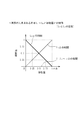
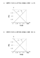
- the correlation value between the pixel value series of each pixel and each of the plurality of code series (L 1 to L 6 ) is theoretically as shown in FIG. Specifically, for the pixel X1, the correlation with the first code sequence L 1 is maximized, and the correlation with the other code sequences L 2 to L 6 is minimized. For the pixel X2, the correlation with the second code sequence L 2 is maximized, and the correlation with the other code sequences L 1 , L 3 to L 6 is minimized. For the pixel X3, the correlation with the third code sequence L 3 is maximized, and the correlation with the other code sequences L 1 , L 2 , L 4 to L 6 is minimized.
- each pixel takes a value corresponding to the size of the area occupied by the code sequences L 1 and L 2 .
- the pixels X2 and X3 take values corresponding to the size of the area occupied by the code sequences of the mixed code sequences.
- the processor 9 Based on the correlation value with each of a plurality of code sequences (L 1 to L 6 ) for each pixel as shown in FIGS. 14 and 15, the processor 9 performs one or more codes included in each pixel.
- the series (L 1 to L 6 ) is specified, and the ratio of each code series in each pixel is obtained.
- information defining the relationship between the correlation value with each of the plurality of code sequences (L 1 to L 6 ) and the movement amount is provided.
- the processor 9 is preset, and the processing processor 9 refers to the information shown in FIGS. 16 to 18 to specify the code sequence and the like.
- the code sequence L 2 enters from a state where only the code sequence L 1 exists in a certain pixel (the position of “0” on the horizontal axis in FIG. 16), and the pixel is the code sequence L 2.
- Change of the correlation value between the pixel value series of the pixel and each of the code series (L 1 to L 6 ) until the state is occupied only by (position of “one pixel” on the horizontal axis in FIG. 16) Is shown.
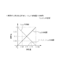
- the code sequence L 3 enters from a state where only the code sequence L 2 exists in a certain pixel (position “0” on the horizontal axis in FIG. 17), and the pixel is the code sequence L 3.
- Change of the correlation value between the pixel value series of the pixel and each of the code series (L 1 to L 6 ) until the state is occupied only by (position of “one pixel” on the horizontal axis in FIG. 16) Is shown.
- the code sequence L 4 enters from a state where only the code sequence L 3 exists in a certain pixel (the position of “0” on the horizontal axis in FIG. 18), and the pixel is the code sequence L 4. Change of the correlation value between the pixel value series of the pixel and each of the code series (L 1 to L 6 ) until the state occupied by only (the position of “one pixel” on the horizontal axis in FIG. 18) Is shown.
- FIGS. 16 to 18 show only three pieces of information (movement amount specifying information) related to the movement of the imaging target in FIGS. 13 to 15, but in reality, they can exist simultaneously in one pixel. Information corresponding to the number of combinations of code sequences that have a characteristic is set in the storage unit 10.
- the processing processor 9 stores information (movement amount) stored in the storage unit 10. (Specific information) is searched, and information that fits the obtained correlation value is selected.
- the code sequence of the pixel X1 is the code sequence L 1 in the previous time phase (initial time phase; FIG. 13)
- the horizontal axis 0 of the information stored in the storage unit 10
- Information having the maximum correlation value with the code sequence L 1 at the position is selected.
- the code sequence L 2 enters with reference to the information shown in FIG. It is determined that the amount of movement that has been made is “0.25”.
- the movement amount (ratio of the pixels) of the mixed code sequence and the code sequence that has entered can be obtained. it can.
- FIG. 19 shows an image of an analysis result when subpixel analysis and pixel analysis are performed on an imaging target (phantom) that sine-moves in the left-right direction.
- the movement becomes a sine movement as indicated by a solid line (theoretical position) in FIG.
- the position can be detected only in units of 1 mm.
- the subpixel analysis since a movement of less than 1 mm can be detected, a position close to the theoretical position can be detected.
- the code sequence (position information) is assigned to each pixel.
- the target to which the code sequence (position information) is assigned is not limited to one pixel, but may be an image region including a plurality of pixels. Good.
- the code sequence when the target to which the code sequence (position information) is assigned is an image region composed of N L pixels in one time-series tagging MR image, the code sequence is not in the N L direction but in the image direction (two-dimensional X direction or Y direction of an image, or X direction, Y direction, or Z direction of a three-dimensional image). In this case, it is not necessary to capture a plurality of time-series tagging MR images, and the imaging time can be shortened.
- FIG. 20 shows an example in which code sequences “1, ⁇ 1, ⁇ 1, 1, ⁇ 1, 1, 1” are assigned to the image direction (X direction).
- the image moves to the right.
- the pixel value of the pixel X1 is This is a value with a blackness of intensity corresponding to the size of the black area occupying the pixel X1. Further, when the black region portion moves from the adjacent pixel to a pixel in which only the black region portion is captured (for example, the pixel X3 in FIG. 21), the pixel value of the pixel X3 is the white region occupying the pixel X3. It becomes a value with whiteness of strength according to the size.
- the pixel value (luminance) and the movement amount when the black area portion moves to the white area pixel are: It is shown as in FIG. Further, the pixel value (luminance) and the movement amount when the white area portion moves to the black area pixel are shown as in FIG.
- the pixel values in FIG. 24 are normalized with the pixel values in the time-series MR image without the tag pattern for the same motion of the same imaging target.
- the pixel value may be different even in the same white region or black region, and the tag pattern disappears over time (for example, the black region also becomes a white region)
- the relationship shown in FIG. 24 can be applied even if different pixel values (brightness) are obtained depending on conditions.
- normalization may be performed using pixel values of white regions or black regions in the same time phase, or their contrasts, not pixel values in a time-series MR image without a tag pattern.
- ratios f w and f B are obtained by normalizing the pixel value of a certain pixel. For example, when the black region of the tag pattern disappears as time passes, the value taken by the black region for each time phase changes because it approaches the value of the white region. In order to cope with this, in the time-series MR image in which the tag pattern is not attached to the same motion of the same imaging target, the same time phase and the same position as the pixel for which the ratios f w and f B are calculated.
- the pixel value of the pixel for which the ratios f w and f B are to be calculated is divided by the pixel value of the corresponding pixel.
- the pixel value of the pixel value to be calculated is normalized by a value from “1” (only the white area) to “0” (only the black area), and the value becomes f W.
- f B can be obtained by the calculation of [1 ⁇ f W ].
- the amount of movement (amount of movement) of the white area or the black area from the ratios f w and f B to the calculation target pixel is less than one pixel using the relationship shown in FIG. It can be determined by size.
- the moving direction can be estimated based on the arrangement of the white area or the black area in the past time phase or the pixel values of the pixels around the calculation target pixel, but assumes a regular left-right sine motion. In this case, it is possible to analyze the motion only by knowing the movement amount.
- the pixel region to which the code sequence (position information) is assigned is a one-dimensional (only in the X direction) region, but may be a two-dimensional or three-dimensional region.
- a two-dimensional image is a three-dimensional region of the image X direction, the image Y direction, and the imaging direction.
- it may be a four-dimensional region in the image X direction, the image Y direction, the image Z direction, and the imaging direction.
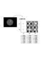
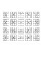
- the tag pattern shown in FIG. 25A is a pattern for extending the modification to two dimensions. This pattern is a pattern having horizontal stripes (horizontal stripe pattern) and vertical stripes (vertical stripe pattern) as shown in FIG. In the pattern of FIG.
- the shaded area is a black area
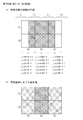
- the white area is a white area.
- FIG. 27B shows other examples in which the modification examples are extended to two dimensions.
- the pattern shown in FIG. 27B is also a pattern having horizontal stripes (horizontal stripe pattern) and vertical stripes (vertical stripe pattern).
- the shaded area is a black area
- the white area is a white area.
- the distinction between the pixels A ′, F ′, K ′, P ′, and U ′ and the pixels A, F, K, P, and U ′ includes nine pixels (its own pixels). And 8 pixels in the vicinity thereof; 3 ⁇ 3 pixel area), and further discrimination by focusing on peripheral pixels (for example, the own pixel and 24 pixels in the vicinity thereof; 5 ⁇ 5 pixel area) Is possible. Note that all 30 pixels may be encoded in a 5 ⁇ 5 pixel area.
- the matter disclosed above is an exemplification, and does not limit the present invention, and various modifications are possible.
- the pixel signal may be a phase value instead of or in addition to the luminance value.
- the motion analysis instead of simply detecting movement or the like, the elastic modulus of the imaging target may be obtained from the detected movement amount.
- the imaging object of the present invention is not particularly limited. However, from the viewpoint of analysis accuracy, the basic form is retained even if movement, contraction, or expansion occurs in the myocardial tissue, etc., compared to an imaging target that does not have a basic form such as fluid such as blood. The imaging target is preferable because good analysis accuracy can be easily obtained.
- the portion located upstream in the blood flow direction overtakes the portion located downstream, and the continuous arrangement relationship of imaging objects (blood flow) in a certain time phase is There is a possibility that it will collapse at a later time phase, making it difficult to obtain good analysis accuracy.
- myocardial tissue is a continuum that maintains the continuous positional relationship of myocardial tissue in a certain phase even if it moves (moves / contracts / expands). Easy to get.
Landscapes
- Health & Medical Sciences (AREA)
- Physics & Mathematics (AREA)
- Engineering & Computer Science (AREA)
- Life Sciences & Earth Sciences (AREA)
- Nuclear Medicine, Radiotherapy & Molecular Imaging (AREA)
- General Health & Medical Sciences (AREA)
- General Physics & Mathematics (AREA)
- Radiology & Medical Imaging (AREA)
- High Energy & Nuclear Physics (AREA)
- Pathology (AREA)
- Heart & Thoracic Surgery (AREA)
- Veterinary Medicine (AREA)
- Public Health (AREA)
- Animal Behavior & Ethology (AREA)
- Vascular Medicine (AREA)
- Biophysics (AREA)
- Signal Processing (AREA)
- Biomedical Technology (AREA)
- Condensed Matter Physics & Semiconductors (AREA)
- Medical Informatics (AREA)
- Molecular Biology (AREA)
- Surgery (AREA)
- Oral & Maxillofacial Surgery (AREA)
- Dentistry (AREA)
- Physiology (AREA)
- Multimedia (AREA)
- Computer Vision & Pattern Recognition (AREA)
- Theoretical Computer Science (AREA)
- Magnetic Resonance Imaging Apparatus (AREA)
Abstract
Description
[1.MRI装置の構成]
本実施形態に係るMRI装置1は、本発明の位置情報符号化MRI法による撮像が行えるものである。本実施形態における位置情報符号化MRI法は、撮像対象物(例えば、人体の組織)を磁気的に標識(タギング)するタギングMRI法を利用するため、前記MRI装置1は、タギングMRI法による撮像が行えるように構成されている。なお、撮像対象を重畳されるタグとしては、任意の方向の縞状又は格子状のものを生成できる。
また、本実施形態では、解析対象の運動として、心壁の運動を例として説明するが、本発明における撮像対象物や解析対象の運動がこれらに限られるものではない。
また、MRI装置1は、RFコイル3から発信される所定のRFパルスを生成するためのRF送信部4と、RFコイル3にて受信した受信信号(MRI信号)を処理するためのRF受信部5と、を備え、RF送信部4で生成しRFコイル3から発信されるRFパルスと磁場発生部2で生成される傾斜磁場の組み合わせによりタグパルスシーケンスを生成できる。
RF受信部5から出力されたMRI信号は、A/D変換部4を介して、コンピュータ8に与えられる。コンピュータ8は、取得したMRI信号に基づいて、画像処理や後述の運動解析等の処理を行う。
また、コンピュータ8は、RF送信部4及び制御部6に対して、必要な指令を与えて、これらを制御する。
図2は、MRI装置1の撮像対象(心臓)の運動解析処理の手順を示している。この運動解析処理は、MRI装置1が、複数回(NL回)のcine撮像(動画撮像)を行う撮像工程(ステップS1)、及び、コンピュータ8が、撮像工程によって得たNL個のcineMR画像(時系列MR画像)に基づいて撮像対象の運動の解析処理を行う解析処理工程(ステップS2)に大別される。
ステップS1の撮像工程では、同一撮像対象の同じ動きを同一撮影範囲で、NL回のcine撮像を繰り返し行う。これらのNL回の撮像は、それぞれ、異なるNL種類のタグパターンで行われる。つまり、ステップS1の撮像工程によって、撮像対象の同じ動きを示すものの、画像中のタグパターンが互いに異なるNL個の時系列タギングMR画像(cineタギングMR画像)が得られる。
図4のFLASHシーケンスは、1回の静止タギングMR画像を撮像するためのものであり、1回のcine撮像あたり、図示のFLASHシーケンスがM回繰り返され、M個の静止タギングMR画像からなる時系列タギングMR画像が得られる。ここで、1個の静止タギングMR画像を一つの時相とすると、M個の静止タギングMR画像からなる時系列タギングMR画像は、M時相分の時系列タギングMR画像となる。
なお、FLASHシーケンスは、例えば、エコー時間TE=12msとし、励起RFパルスにフリップ角α=30度のhermiteパルスを利用することができる。
なお、MRIの撮影シーケンスは、FLASHシーケンスに限られるものではなく、タグパターンを生成するためのシーケンスもDANTEシーケンスに限られるものではない。
また、図5(a)における第1cine(#1)から第NLcine(#NL)は、それぞれ、図4のFLASHシーケンスに対応し、第1回目のcine撮像(#1)から第NL回目のcine撮像(#NL)をするためのものである。
つまり、撮像対象が心臓である場合、図5(b)に示すように繰り返される心拍において、例えば、1心拍分の時間の間において、1回のcine撮像を行うものとする。そして、各回のcine撮像は、心拍周期に関して同一のタイミング(時相)で行われる。
この結果、各回のcine撮像では、心臓の同じ運動を撮像することになる。したがって、各回(1回目からNL回目)の時系列タギングMR画像において、画像中の心臓の位置・形状は、同一時相であれば同じ位置・形状となる。
ステップS2の解析処理工程では、コンピュータ8が、ステップS1の撮像工程によって得たNL個の時系列タギングMR画像に基づいて撮像対象の運動の解析処理を行う。
具体的には、図6に示すように、まず、コンピュータ8は、タギング画像の各画素それぞれについて存在するNL個の画素値を、当該画素についての長さNLの画素値系列(長さNLの信号)とする処理を行う(ステップS21)。なお、ここでの画素値は、画素の輝度値であるが、画素の位相値であってもよい。
図7に示すように、NL個の時系列タギングMR画像を、時相をそろえて並べた場合、各時相それぞれについて、タギング画像がNL枚得られたことになる。したがって、タギング画像の個々の画素に着目すると、各時相の各画素について、NL個の画素値が存在することになり、これらNL個の画素値を撮像順に並べて、長さNLの画素値系列とする。
具体的には、各時相において、同一符号系列を持つ画素の位置を記憶部10に記憶しておき、また、同一符号系列を持つ画素の移動軌跡を表示部11に表示することで、装置1のユーザは、撮像対象の運動の様子を的確に把握することができる。
この場合、初期時相における画素(x1,y1)が符号系列L1を送信した送信局であり、第MX時相における画素(x2,y2)が当該送信局から送信された符号系列L1を受信した受信局であるとみなすことができる。通信において、受信局は、受信信号(画素値系列)を復号することにより受信信号が示す符号系列を識別することができる。
したがって、本実施形態における上記の移動軌跡の追跡は、符号系列L1を受信した受信局(画素)を検出することと同様である。
また、タギングMR画像では、時相の経過によって、タグコントラストが低下するため、第MX時相における画素の画素値系列は、低SN比となり、劣悪な通信環境に類似することになる。しかし、通信において、適切な符号系列を選択することで、劣悪な通信環境に対応できるのと同様に、適切な符号系列を選択することで、タギングMR画像におけるタグコントラストの低下にも対応することができる。
しかし、心壁の厚さは10mm程度であるため、このような間隔ではタグ領域が最大でも2回程度しか現れず、壁の厚み方向における運動の差違に関する詳細な検討は難しかった。
前記符号系列として、耐雑音特性、耐混信特定の高いものを用いることで、符号系列が割り当てられた画素の位置を高い精度で特定することができる。例えば、符号系列としては拡散符号を用い、スペクトル拡散(Spread
Spectrum; SS)を行うことができる。スペクトル拡散とは、狭帯域変調信号を拡散符号によって数百~数千倍のスペクトルを持つ広帯域信号に変調して伝送し、受信側で元の狭帯域信号に変換した後に復調する通信方式である。SSには耐妨害性、劣悪な伝送路に強いという特長がある。
このように、スペクトラム拡散の劣悪な伝送路に強いという性質を利用することで、時相の経過によるタグコントラストの低下に対し、精度の高い運動解析が可能となる。
なお、上記の拡散符号系列、PN系列、及びM系列は、いずれも符号がほぼ直交する直交性を有しており、直交符号系列でもある。
[4.1.相関関数の計算]
長さNL、系列数Nsの符号系列の集合をLとする。符号系列集合Lのi番目の符号系列をLi(1≦i≦Ns)とし、各符号要素をlij(1≦i≦Ns,1≦j≦NL)とする。ただし、lij∈{1,-1}とする。情報符号S^∈{1,-1}を拡散符号系列Liで拡散した結果をS(i)={Sj (i)}(1≦j≦NL)とする。このとき、Sj (i)=S^×lij∈{1,-1}となる。
符号系列LkとSj (i)との相関関数Φkは次のように計算される。ただし、本実施形態の手法では、τ=0しか生じないため、相関関数もτ=0でのみ計算するものとし、また、簡単のためS^=1とする。




あるFOV(Field Of View)について、解像度WMTX[pixel]、時相間の間隔tph[sec]でM時相分のcine撮像を行うものとする。時刻t=tph×pにおける画素(x,y)の画素値(画像信号)をa(x,y,p)と表す。ただし、初期時相(第1時相)の時刻はt=tph×0とするため、0≦p≦M-1である。
ここで、長さNLの拡散符号系列Li={lij}を考える。画素値a(x,y,p)と拡散符号lij(j=1,2,・・・,NL)の積を取ると、スペクトル拡散変調された画素値g(i)(x,y,p,j)が得られる。得られる画像の画素値g(i)(x,y,p,j)を簡単のため、mj (i)とおき、MRIタギング法を用いた変調を考えると、





ここでは、符号系列としてM系列を利用する。M系列は、NL=2n-1の符号長、系列数を持ち、τ=0における自己相関値と相互相関値の比が-NL:1となる。本実施形態において、画素値系列から符号系列を特定する際には、自己相関値がピークを持っていることが望ましいため、NLは大きいことが望まれる。一方、NLが大きいと、NL個の時系列タギングMR画像を撮像する必要があり、撮像に時間を要する。そこで、ここでは、NL=7とした。
NL=7のM系列として、2次の原始多項式x2+x+1で生成される符号系列を用いた。前述のDANTEタギングシーケンス(又はSPAMMタギングシーケンス)では、一定長さのタグ領域と一定長さの非タグ領域が交互に繰り返す周期的なタグパターンが実現できるため、生成した7つのM系列から符号系列を選択し、適切に空間配置することで、全ての撮影において周期的なタグパターンを成すことができる。

図9の各タグパターンは、対応する画像領域(18×18画素分)内の各画素に、図10に示すように、符号系列L1~L6を割り当てた場合のものである。各画素に割り当てられた符号系列L1~L6は、画素の位置情報を示していることになる。
図11(a)~(c)は、図12に示すファントム(撮像対象)が、左右方向に正弦運動する様子をタギングMRI装置1にて撮影した結果を示している。
図11(a)は、図9に示す7つのタグパターンにて7個のcine画像をMRI装置1にて撮像し(NL=7)、先に説明したNL=7のM系列にて、ファントムの位置の変位を判定した結果を示している。
図11(a)においては、判定した符号系列L1~L6を、画素の明暗で区別して示している。つまり、図11(a)においては、明暗度が同じ画素は同一の符号系列であると判定された画素となっている。
また、図11(c)は、上記M系列を構成する7個のcine画像のうち、タグ領域(低輝度領域)及び非タグ領域(高輝度領域)それぞれの左右幅が3mm(3画素分)のタグパターン(1画素の幅を1mmとすると図9の第3~第5タグパターンのいずれかに相当)でファントムを撮影した画像である。
これに対し、図11(b)に示す1mm幅のタギングMRI画像では、タグ領域及び非タグ領域が細いため、両領域のコントラストが低くなり、第10時相までにタグパターンは消失し、それ以降の追跡ができない。
また、図11(c)に示す3mm幅のタギングMRI画像では、M系列による判定結果と同様に、第13~14時相まで淡いコントラストでタグパターンを追跡できるが、太いタグパターンのため、位置判定の分解能は3mmにすぎない。
上記のM系列による判定では、1画素単位の解析(Pixel analysis)となり、位置検出の精度は1画素単位である。したがって、1画素未満の移動量を検出することはできない。
図13に示すように、初期時相では、撮像対象に標識されたタグパターンにおける低輝度領域(黒領域)と高輝度領域(白領域)との境界は、画素の境界と一致している。図13において、黒領域の横幅は、ちょうど2画素分である。
ここでは、画素値系列と特定の符号系列との相関値を0~1で表し、「1」の場合、相関が最も高く、「0」の場合、相関が最も低いものとする。
図14(a)に示すように、画素X1については、第1符号系列L1及び第2符号系列L2が混在している。このため、他の符号系列L3~L6との相関は最小となるのに対し、第1符号系列L1との相関は0.75、第2符号系列L2との相関は0.25というように、各画素において符号系列L1,L2が占める領域の面積の大小に応じた値をとる。画素X2,X3についても同様に、混在する符号系列についてそれらの符号系列が占める領域の面積の大小に応じた値をとる。
そして、符号系列L1との相関値=0.75及び符号系列L2との相関値=0.25という混在状況に基づいて、図16に示す情報を参照して、符号系列L2が進入してきた移動量は「0.25」であると判定する。
また、図16~図18に示す情報(移動量特定情報)では、相関値と移動量との関係が線形となっているが、実際には、非線形となることが多い。相関値と移動量との関係が非線形性となる場合は、各符号系列の組み合わせ毎に、予め符号系列から計算により求めて置いた関係、あるいは予め実測によりもとめておいた関係を、移動量特定情報として用いるのが好ましい。
図19は、左右方向に正弦運動する撮像対象(ファントム)に対してサブピクセル解析とピクセル解析とを行った場合の解析結果のイメージを示している。撮像対象のある点に着目すると、図19における実線(理論位置)で示すように、運動は正弦運動となる。この撮像対象に対して、ピクセル解析を行った場合、位置は、1mm単位でしか検出できないことになる。これに対し、サブピクセル解析では、1mm未満の移動も検出できるため、理論位置に近い位置を検出することが可能となる。
上記実施形態では、一つの画素それぞれに符号系列(位置情報)を割り当てたが、符号系列(位置情報)を割り当てる対象は、一つの画素に限らず、複数の画素からなる画像領域であってもよい。
例えば、図示のように、時相t=t1の符号系列「1,-1,-1,1,-1,1,1」の位置と同じ位置で相関をとった場合、その位置から1画素分右へ移動した位置で相関をとった場合、2画素分右へ移動した位置で相関をとった場合、及び3画素分右へ移動した位置で相関をとった場合では、3画素分右へ移動した位置で相関をとった場合に相関が最も高くなり、その他の場合では、相関が-1(最小値)である。したがって、時相t=t1においては、符号系列「1,-1,-1,1,-1,1,1」が割り当てられた領域は、3画素分右へ移動した位置にあることを検出することができる。
この変形例においても、1画素単位の解析(ピクセル解析)だけでなく、1画素未満の解析(サブピクセル解析)を行うことができる。この変形例において、サブピクセル解析を行う場合には、各画素の画素値(輝度値)から移動量(白領域又は黒領域の占める割合)を求める。
つまり、タグパターンにおいて、白領域と黒領域の境界が1つの画素中に位置した場合、図22(b)及び図23(b)のように、その画素は、白領域と黒領域との間の中間色(中間輝度)となる。例えば、白領域部分だけが撮影された画素(例えば図21の画素X1)に、隣の画素(例えば、図21の画素X2)から黒領域部分が移動してきた場合、その画素X1の画素値は、その画素X1に占める黒領域の大きさに応じた強さの黒みがかかった値となる。
また、黒領域部分だけが撮影された画素(例えば図21の画素X3)に、隣の画素から黒領域部分が移動してきた場合、その画素X3の画素値は、その画素X3に占める白領域の大きさに応じた強さの白みがかかった値となる。
例えば、時間が経つにつれて、タグパターンの黒領域が消失する場合、時相ごとに黒領域がとる値は、白領域の値に近づいていくため変化する。これに対処するには、同じ撮像対象の同じ運動についてタグパターンが付されていない時系列MR画像において、割合fw,fBの算出対象となっている画素と、同一時相かつ同一位置の画素(対応画素)に着目する。正規化では、割合fw,fBの算出対象となっている画素の画素値を、対応画素の画素値で除算する。これにより、算出対象の画素値の画素値は、「1」(白領域のみ)から「0」(黒領域のみ)の値で正規化され、その値がfWとなる。fBは、[1-fW]の演算で求めることができる。
なお、図20において、符号系列(位置情報)が割り当てられる画素の領域は、1次元(X方向のみ)の領域であったが、2次元又は3次元の領域であってもよい。また、図7に示す複数回(例えば、NL回)の撮像方向も加えて考えた場合、2次元画像であれば画像X方向、画像Y方向、及び撮像方向の3次元における領域であってもよいし、3次元画像であれば、画像X方向、画像Y方向、画像Z方向、及び撮像方向の4次元における領域であってもよい。
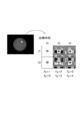
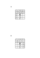
図25(a)に示すタグパターンは、変形例を2次元に拡張するためのパターンである。このパターンは、図25(b)にも示すように、横縞(水平の縞模様)と縦縞(垂直の縞模様)とを有するパターンである。図25(b)のパターンは、画像の縦方向にみたときに、横縞の白領域(白帯)幅:黒領域(黒帯)幅=3:1であり、画像の横方向にみたときに、縦縞の白領域(白帯)幅:黒領域(黒帯)幅=3:2である。なお、図25(b)の斜線部分が黒領域であり、白抜き領域が白領域である。
A-Tの20個の画素について、それぞれを中心とする例えば9個の画素(自身の画素及びその近傍の8個の画素;3×3画素の領域)の白黒パターンに注目すると、図26に示すように、20個の3×3画素の領域は、すべて異なる白黒パターンとなっている。これは、20個の画素に特有の画像パターン(長さNL=9の符号系列;位置情報)とみなすことができ、タグパターンによって画像の各画素をコーディングできたことと等価である。
図27(b)に示すパターンも、横縞(水平の縞模様)と縦縞(垂直の縞模様)とを有するパターンである。図27(b)のパターンは、画像の縦方向にみたときに、横縞の白領域(白帯)幅:黒領域(黒帯)幅=3:2であり、画像の横方向にみたときに、縦縞の第1白領域幅:第1黒領域幅:第2白領域幅:第2黒領域幅=3:1:1:1である。なお、図27(b)の斜線部分が黒領域であり、白抜き領域が白領域である。
A-Yの30個の画素について、それぞれを中心とする例えば9個の画素(自身の画素及びその近傍の8個の画素;3×3画素の領域)の白黒パターンに注目すると、A’,F’,K’,P’,U’は、A,F,F,P,Uと同じパターンになるため、図28に示すように、25個の白黒パターンが得られ、これら25個の3×3画素の領域は、すべて異なる白黒パターンとなっている。これは、25個の画素に特有の画像パターン(長さNL=9の符号系列;位置情報)とみなすことができ、タグパターンによって25個の画素をコーディングできたことと等価である。
例えば、画素信号が、輝度値に代えて、又は加えて、位相値であってもよい。
また、運動解析としては、単に、移動などを検出するのではなく、検出された移動量から撮像対象の弾性率を求めるものであってもよい。
さらに、本発明の撮像対象は、特に限定されない。ただし、解析精度の観点からは、血液などの流体のように基本的形態を持たない撮像対象よりも、心筋組織などのように移動・収縮・拡張などが生じるとしても基本的形態が保持される撮像対象の方が、良好な解析精度を得やすく好ましい。つまり、例えば血流を想定すると、血流方向の上流側に位置する部分が、下流側に位置する部分を追い越してしまい、ある時相における撮像対象(血流)の連続的な配置関係が、後の時相では崩れてしまう可能性があり、良好な解析精度を得るのを困難にする。一方、心筋組織は、運動(移動・収縮・拡張)しても、ある時相における心筋組織の連続的な配置関係が維持される連続体であるため、解析が容易となり、良好な解析精度を得るのが容易となる。
2 磁場発生部
3 RFコイル
4 RF送信部
5 RF受信部
6 制御部
7 A/D変換部
8 コンピュータ
9 処理プロセッサ
10 記憶部
11 表示部
Claims (16)
- タギングMR画像における撮像対象の運動解析方法であって、
撮像対象の同じ運動に対して、異なるタグパターンよるNL回(NLは2以上の正の整数)のcine撮像をすることで、前記撮像対象の前記運動における複数の時相について撮像された時系列のタギングMR画像をNL個得る工程と、
各時相のNL個のタギングMR画像における同一画素についてのNL個の画素値を、当該画素についての長さNLの画素値系列とする工程と、
異なる時相において、前記画素値系列が同一の符号系列を構成する画素を検出することで、時系列のタギングMR画像における撮像対象の運動を解析する工程と、
を含み、
前記タグパターンそれぞれは、前記画素値系列が、所定の符号系列を構成するようにパターンが形成されたものである、
ことを特徴とするタギングMR画像における撮像対象の運動解析方法。 - 撮像対象の運動を解析する前記工程では、前記画素値系列に基づいて、各画素において混在する複数の符号系列それぞれが占める割合を算出し、当該割合に基づいて、1画素の大きさ未満での撮像対象の運動量を算出する
請求項1記載の運動解析方法。 - 前記符号系列は、直交符号系列である請求項1記載のタギングMR画像における撮像対象の運動解析方法。
- 前記符号系列は、拡散符号系列である請求項1記載のタギングMR画像における撮像対象の運動解析方法。
- 前記符号系列は、PN系列である請求項1記載のタギングMR画像における撮像対象の運動解析方法。
- 前記符号系列は、M系列である請求項1記載のタギングMR画像における撮像対象の運動解析方法。
- タギングMR画像における撮像対象の運動解析方法であって、
撮像対象に対し、所定のタグパターンでcine撮像することで、前記撮像対象の運動における複数の時相について撮像された時系列のタギングMR画像を得る工程と、
各時相のタギングMR画像に含まれるNL個(NLは2以上の正の整数)の画素それぞれの画素値を、当該NL個の画素からなる領域についての長さNL個の画素値系列とする工程と、
異なる時相において、前記画素値系列が同一の符号系列を構成する領域を検出することで、時系列のタギングMR画像における撮像対象の運動を解析する工程と、を含み、
前記所定のタグパターンは、前記画素値系列が、所定の符号系列を構成するようにパターンが形成されたものである、
ことを特徴とするタギングMR画像における撮像対象の運動解析方法。 - 撮像対象の運動を解析する前記工程では、各画素の画素値の大きさに基づいて、タグパターンの明領域又は暗領域が各画素の範囲内において本来占めるべき割合を算出し、当該割合に基づいて1画素の大きさ未満での撮像対象の運動量を算出する
請求項7記載の運動解析方法。 - MRI装置であって、
撮像対象の同じ運動に対して、異なるタグパターンよるNL回(NLは2以上の正数)のcine撮像をすることで、前記撮像対象の前記運動における複数の時相について撮像された時系列のタギングMR画像をNL個得る手段と、
特定の時相のNL個のタギングMR画像における同一画素についてのNL個の画素値からなる画素値系列を、前記特定の時相において当該画素を示す長さNLの符号系列とみなし、前記符号系列と同じ符号系列となる画素値系列を持つ画素を、前記特定の時相以外の時相のNL個のタギングMR画像において検出することで、時系列のタギングMR画像における撮像対象の運動を解析する手段と、
を備え、
前記タグパターンそれぞれは、前記画素値系列が、所定の符号系列を構成するようにパターンが形成されたものである、
ことを特徴とするMRI装置。 - 撮像対象の運動を解析する前記手段では、前記画素値系列に基づいて、各画素において混在する複数の符号系列それぞれが占める割合を算出し、当該割合に基づいて、1画素の大きさ未満での撮像対象の運動量を算出する
請求項9記載のMRI装置 - 前記符号系列は、直交符号系列である請求項9記載のMRI装置。
- 前記符号系列は、拡散符号系列である請求項9記載のMRI装置。
- 前記符号系列は、PN系列である請求項9記載のMRI装置。
- 前記符号系列は、M系列である請求項9記載のMRI装置。
- MRI装置であって、
撮像対象に対し、所定のタグパターンでcine撮像することで、前記撮像対象の運動における複数の時相について撮像された時系列のタギングMR画像を得る手段と、
特定の時相のタギングMR画像に含まれるNL個(NLは2以上の正の整数)の画素それぞれの画素値からなる画素値系列を、当該NL個の画素からなる領域を示す長さNLの符号系列とみなし、前記符号系列と同じ符号系列となる画素値系列を持つ領域を、前記特定の時相以外の時相のタギングMR画像において検出することで、時系列のタギングMR画像における撮像対象の運動を解析する手段と、
を備え、
前記所定のタグパターンは、前記画素値系列が、所定の符号系列を構成するようにパターンが形成されたものである、
ことを特徴とするMRI装置。 - 撮像対象の運動を解析する前記手段では、各画素の画素値の大きさに基づいて、タグパターンの明領域又は暗領域が各画素の範囲内において本来占めるべき割合を算出し、当該割合に基づいて1画素の大きさ未満での撮像対象の運動量を算出する
請求項15記載のMRI装置。
Priority Applications (2)
| Application Number | Priority Date | Filing Date | Title |
|---|---|---|---|
| JP2011511330A JP5419024B2 (ja) | 2009-04-30 | 2010-01-08 | タギングmr画像における撮像対象の運動解析方法及びmri装置 |
| US13/266,244 US8538104B2 (en) | 2009-04-30 | 2010-01-08 | Method of analyzing motion of imaging target by means of tagged MR images, and MRI device |
Applications Claiming Priority (2)
| Application Number | Priority Date | Filing Date | Title |
|---|---|---|---|
| JP2009111371 | 2009-04-30 | ||
| JP2009-111371 | 2009-04-30 |
Publications (1)
| Publication Number | Publication Date |
|---|---|
| WO2010125832A1 true WO2010125832A1 (ja) | 2010-11-04 |
Family
ID=43031988
Family Applications (1)
| Application Number | Title | Priority Date | Filing Date |
|---|---|---|---|
| PCT/JP2010/050173 Ceased WO2010125832A1 (ja) | 2009-04-30 | 2010-01-08 | タギングmr画像における撮像対象の運動解析方法及びmri装置 |
Country Status (3)
| Country | Link |
|---|---|
| US (1) | US8538104B2 (ja) |
| JP (1) | JP5419024B2 (ja) |
| WO (1) | WO2010125832A1 (ja) |
Cited By (1)
| Publication number | Priority date | Publication date | Assignee | Title |
|---|---|---|---|---|
| JP2020081722A (ja) * | 2018-11-30 | 2020-06-04 | 学校法人慶應義塾 | 磁気共鳴イメージング方法及び磁気共鳴イメージング装置 |
Families Citing this family (4)
| Publication number | Priority date | Publication date | Assignee | Title |
|---|---|---|---|---|
| US8538104B2 (en) * | 2009-04-30 | 2013-09-17 | Kyoto University | Method of analyzing motion of imaging target by means of tagged MR images, and MRI device |
| US9671482B2 (en) | 2012-10-18 | 2017-06-06 | Samsung Electronics Co., Ltd. | Method of obtaining image and providing information on screen of magnetic resonance imaging apparatus, and apparatus thereof |
| DE102016214775A1 (de) * | 2016-08-09 | 2018-02-15 | Siemens Healthcare Gmbh | Bestimmung einer Eigenschaft eines Organs |
| KR101784502B1 (ko) * | 2016-09-05 | 2017-11-06 | 성균관대학교산학협력단 | 동적 태그 자기 공명 영상 장치 및 방법 |
Citations (1)
| Publication number | Priority date | Publication date | Assignee | Title |
|---|---|---|---|---|
| JP2007190114A (ja) * | 2006-01-18 | 2007-08-02 | Hitachi Medical Corp | 磁気共鳴イメージング装置 |
Family Cites Families (6)
| Publication number | Priority date | Publication date | Assignee | Title |
|---|---|---|---|---|
| ATE545873T1 (de) * | 1999-04-22 | 2012-03-15 | Univ Johns Hopkins | Messung der herzbewegung durch magnetresonanzbildgebung mit kineharmonischen phasen |
| JP3877926B2 (ja) * | 2000-02-22 | 2007-02-07 | 株式会社日立製作所 | 核磁気共鳴撮影装置 |
| JP4342809B2 (ja) * | 2003-02-14 | 2009-10-14 | 株式会社東芝 | Mri装置 |
| US7813537B2 (en) * | 2006-05-15 | 2010-10-12 | Siemens Medical Solutions Usa, Inc. | Motion-guided segmentation for cine DENSE images |
| US8538104B2 (en) * | 2009-04-30 | 2013-09-17 | Kyoto University | Method of analyzing motion of imaging target by means of tagged MR images, and MRI device |
| US8581582B2 (en) * | 2009-09-18 | 2013-11-12 | Kabushiki Kaisha Toshiba | MRI non-contrast time-slip angiography using variably positioned cine sub-sequence |
-
2010
- 2010-01-08 US US13/266,244 patent/US8538104B2/en not_active Expired - Fee Related
- 2010-01-08 WO PCT/JP2010/050173 patent/WO2010125832A1/ja not_active Ceased
- 2010-01-08 JP JP2011511330A patent/JP5419024B2/ja not_active Expired - Fee Related
Patent Citations (1)
| Publication number | Priority date | Publication date | Assignee | Title |
|---|---|---|---|---|
| JP2007190114A (ja) * | 2006-01-18 | 2007-08-02 | Hitachi Medical Corp | 磁気共鳴イメージング装置 |
Non-Patent Citations (1)
| Title |
|---|
| YU SHIMIZU ET AL.: "Shinzo 3-jigen MRI Tagging Gazo kara no Tag Kosaten Kenshutsuho", DAI 26 KAI JAPANESE SOCEITY OF MEDICAL IMAGING TECHNOLOGY TAIKAI SHOROKU-SHU (CD-ROM), 2007 * |
Cited By (2)
| Publication number | Priority date | Publication date | Assignee | Title |
|---|---|---|---|---|
| JP2020081722A (ja) * | 2018-11-30 | 2020-06-04 | 学校法人慶應義塾 | 磁気共鳴イメージング方法及び磁気共鳴イメージング装置 |
| JP7233902B2 (ja) | 2018-11-30 | 2023-03-07 | 慶應義塾 | 磁気共鳴イメージング方法及び磁気共鳴イメージング装置 |
Also Published As
| Publication number | Publication date |
|---|---|
| JPWO2010125832A1 (ja) | 2012-10-25 |
| JP5419024B2 (ja) | 2014-02-19 |
| US8538104B2 (en) | 2013-09-17 |
| US20120045107A1 (en) | 2012-02-23 |
Similar Documents
| Publication | Publication Date | Title |
|---|---|---|
| JP7246866B2 (ja) | 医用画像処理装置 | |
| Qi et al. | Non-rigid respiratory motion estimation of whole-heart coronary MR images using unsupervised deep learning | |
| JP5419024B2 (ja) | タギングmr画像における撮像対象の運動解析方法及びmri装置 | |
| Song et al. | Improving the spatial resolution of landsat TM/ETM+ through fusion with SPOT5 images via learning-based super-resolution | |
| IL301395A (en) | Motion-compensated laser speckle contrast imaging | |
| US9361686B2 (en) | Method and apparatus for the assessment of medical images | |
| CN113272869A (zh) | 医学成像中从定位片进行三维形状重构 | |
| CN101297321A (zh) | 配准图像的方法,用于执行配准图像的方法的算法,用于使用所述算法配准图像的程序以及处理生物医学图像以减少由对象移动导致的成像伪影的方法 | |
| CN111065328B (zh) | 用于有策略地获取的梯度回波成像的系统和方法 | |
| US20140105475A1 (en) | Image processing apparatus and image processing method | |
| US20010007593A1 (en) | Method and unit for displaying images | |
| WO2013094152A1 (ja) | 画像処理装置および画像処理方法、並びに、画像処理プログラム | |
| Zhang et al. | LPAQR-Net: efficient vertebra segmentation from biplanar whole-spine radiographs | |
| JP2004535871A (ja) | 組織構造および組織構造の時間変化を定量化するためのシステムおよび方法 | |
| Kalpana et al. | MRI and SPECT brain image analysis using image fusion | |
| JP6629247B2 (ja) | 微細構造解析データのデータ品質を評価し向上させる方法 | |
| Gao et al. | CT‐based synthetic iodine map generation using conditional denoising diffusion probabilistic model | |
| CA3245137A1 (en) | Motion-Compensating Laser Granularity Contrast Imaging | |
| Mazaheri et al. | Hybrid Pixel‐Based Method for Cardiac Ultrasound Fusion Based on Integration of PCA and DWT | |
| KR20230060888A (ko) | 의료 이미지 스티칭 방법 및 장치 | |
| Lin et al. | GMmorph: dynamic spatial matching registration model for 3D medical image based on gated Mamba | |
| Xue-jun et al. | A medical image fusion algorithm based on lifting wavelet transform | |
| WO2017198518A1 (en) | Image data processing device | |
| Jailin et al. | Deformable registration with intensity correction for CESM monitoring response to Neoadjuvant Chemotherapy | |
| Nonsakhoo et al. | A Novel Method for Motion Blur Detection and Quantification Using Signal Analysis on a Controlled Empirical Image Dataset |
Legal Events
| Date | Code | Title | Description |
|---|---|---|---|
| 121 | Ep: the epo has been informed by wipo that ep was designated in this application |
Ref document number: 10769532 Country of ref document: EP Kind code of ref document: A1 |
|
| ENP | Entry into the national phase |
Ref document number: 2011511330 Country of ref document: JP Kind code of ref document: A |
|
| WWE | Wipo information: entry into national phase |
Ref document number: 13266244 Country of ref document: US |
|
| NENP | Non-entry into the national phase |
Ref country code: DE |
|
| 122 | Ep: pct application non-entry in european phase |
Ref document number: 10769532 Country of ref document: EP Kind code of ref document: A1 |