WO2010123789A1 - Thickness-independent computation of horizontal and vertical permeability - Google Patents
Thickness-independent computation of horizontal and vertical permeability Download PDFInfo
- Publication number
- WO2010123789A1 WO2010123789A1 PCT/US2010/031538 US2010031538W WO2010123789A1 WO 2010123789 A1 WO2010123789 A1 WO 2010123789A1 US 2010031538 W US2010031538 W US 2010031538W WO 2010123789 A1 WO2010123789 A1 WO 2010123789A1
- Authority
- WO
- WIPO (PCT)
- Prior art keywords
- permeability
- pressure data
- packer
- horizontal
- probe
- Prior art date
Links
- 230000035699 permeability Effects 0.000 title claims abstract description 164
- 230000015572 biosynthetic process Effects 0.000 claims abstract description 98
- 239000000523 sample Substances 0.000 claims abstract description 82
- 238000000034 method Methods 0.000 claims abstract description 42
- 238000012360 testing method Methods 0.000 claims abstract description 37
- 230000009977 dual effect Effects 0.000 claims abstract description 34
- 239000012530 fluid Substances 0.000 claims abstract description 32
- 238000004519 manufacturing process Methods 0.000 claims description 13
- 238000005755 formation reaction Methods 0.000 description 71
- 238000004458 analytical method Methods 0.000 description 21
- 238000012545 processing Methods 0.000 description 19
- 239000010410 layer Substances 0.000 description 17
- 238000005553 drilling Methods 0.000 description 11
- 238000004891 communication Methods 0.000 description 10
- 238000009877 rendering Methods 0.000 description 8
- 230000001052 transient effect Effects 0.000 description 7
- 230000006870 function Effects 0.000 description 6
- 230000008569 process Effects 0.000 description 6
- 238000005259 measurement Methods 0.000 description 5
- 208000018747 cerebellar ataxia with neuropathy and bilateral vestibular areflexia syndrome Diseases 0.000 description 4
- 230000003068 static effect Effects 0.000 description 4
- 238000003860 storage Methods 0.000 description 4
- 230000008901 benefit Effects 0.000 description 3
- 238000005206 flow analysis Methods 0.000 description 3
- 238000000611 regression analysis Methods 0.000 description 3
- 230000009471 action Effects 0.000 description 2
- 238000009530 blood pressure measurement Methods 0.000 description 2
- 238000011161 development Methods 0.000 description 2
- 238000011156 evaluation Methods 0.000 description 2
- 229930195733 hydrocarbon Natural products 0.000 description 2
- 150000002430 hydrocarbons Chemical class 0.000 description 2
- 229910052500 inorganic mineral Inorganic materials 0.000 description 2
- 238000007726 management method Methods 0.000 description 2
- 239000011707 mineral Substances 0.000 description 2
- 230000004044 response Effects 0.000 description 2
- 239000011435 rock Substances 0.000 description 2
- 238000005070 sampling Methods 0.000 description 2
- 238000012546 transfer Methods 0.000 description 2
- 239000004215 Carbon black (E152) Substances 0.000 description 1
- BVKZGUZCCUSVTD-UHFFFAOYSA-L Carbonate Chemical compound [O-]C([O-])=O BVKZGUZCCUSVTD-UHFFFAOYSA-L 0.000 description 1
- 235000019738 Limestone Nutrition 0.000 description 1
- 230000006399 behavior Effects 0.000 description 1
- 238000004422 calculation algorithm Methods 0.000 description 1
- 238000004364 calculation method Methods 0.000 description 1
- 230000008859 change Effects 0.000 description 1
- 238000012512 characterization method Methods 0.000 description 1
- 238000004590 computer program Methods 0.000 description 1
- 230000000994 depressogenic effect Effects 0.000 description 1
- 238000013461 design Methods 0.000 description 1
- 238000006073 displacement reaction Methods 0.000 description 1
- 230000000694 effects Effects 0.000 description 1
- 230000001747 exhibiting effect Effects 0.000 description 1
- 238000011065 in-situ storage Methods 0.000 description 1
- 239000006028 limestone Substances 0.000 description 1
- 239000004973 liquid crystal related substance Substances 0.000 description 1
- 230000007246 mechanism Effects 0.000 description 1
- 238000005065 mining Methods 0.000 description 1
- 238000012544 monitoring process Methods 0.000 description 1
- -1 oil Chemical class 0.000 description 1
- 230000003287 optical effect Effects 0.000 description 1
- 230000000704 physical effect Effects 0.000 description 1
- 238000011084 recovery Methods 0.000 description 1
- 238000004088 simulation Methods 0.000 description 1
- 239000002356 single layer Substances 0.000 description 1
- 238000009662 stress testing Methods 0.000 description 1
- 238000006467 substitution reaction Methods 0.000 description 1
- 230000001360 synchronised effect Effects 0.000 description 1
- XLYOFNOQVPJJNP-UHFFFAOYSA-N water Substances O XLYOFNOQVPJJNP-UHFFFAOYSA-N 0.000 description 1
Classifications
-
- E—FIXED CONSTRUCTIONS
- E21—EARTH OR ROCK DRILLING; MINING
- E21B—EARTH OR ROCK DRILLING; OBTAINING OIL, GAS, WATER, SOLUBLE OR MELTABLE MATERIALS OR A SLURRY OF MINERALS FROM WELLS
- E21B49/00—Testing the nature of borehole walls; Formation testing; Methods or apparatus for obtaining samples of soil or well fluids, specially adapted to earth drilling or wells
- E21B49/008—Testing the nature of borehole walls; Formation testing; Methods or apparatus for obtaining samples of soil or well fluids, specially adapted to earth drilling or wells by injection test; by analysing pressure variations in an injection or production test, e.g. for estimating the skin factor
Definitions
- Operations such as surveying, drilling, wireline testing, completions, production, planning and field analysis, are typically performed to locate and gather valuable downhole fluids.
- Surveys are often performed using acquisition methodologies, such as seismic scanners or surveyors to generate maps of underground formations. These formations are often analyzed to determine the presence of subterranean assets, such as valuable fluids or minerals, or to determine if the formations have characteristics suitable for storing fluids.
- oilfield and “oilfield operation” may be used interchangeably with the terms “field” and “field operation” to refer to a field having any types of valuable fluids or minerals and field operations relating to any of such subterranean assets.
- data is typically collected for analysis and/or monitoring of the operations.
- data may include, for instance, information regarding subterranean formations, equipment, and historical and/or other data.
- Data concerning the subterranean formation is collected using a variety of sources.
- Such formation data may be static or dynamic.
- Static data relates to, for instance, formation structure and geological stratigraphy that define geological structures of the subterranean formation.
- Dynamic data relates to, for instance, fluids flowing through the geologic structures of the subterranean formation over time. Such static and/or dynamic data may be collected to learn more about the formations and the valuable assets contained therein.
- Permeability is a relevant parameter for managing a reservoir and adjusting well performance. Due to permeability's effect on reservoir displacement processes, the determination of permeability and permeability anisotropy (the ratio of vertical and horizontal permeability, k v /k h ) is becoming increasingly important as emphasis shifts from primary to secondary and tertiary recovery.
- IPTT Interval pressure transient testing along the wellbore using packer- probe formation testers provides dynamic permeability and anisotropy information with increased vertical resolution as compared to conventional well testing.
- IPTT Interval pressure transient testing
- the test tool is positioned at the interval to be tested and flow is induced from a dual packer tool module or from a sink probe while vertically displaced observation probes monitor the pressure response.
- the acquired flow and buildup transient data are used to obtain and analyze individual layer horizontal and vertical permeabilities.
- This testing technique yields formation properties well beyond the invaded zone, usually within "tens of feet" away from the wellbore in horizontal and vertical directions.
- thickness-independent computation of horizontal and vertical permeability relates to a method for determining permeability of a reservoir using a packer-probe formation testing tool.
- the elements of the method include generating, using a dual packer tool module, fluid flows from the reservoir into a wellbore, obtaining pressure data associated with the fluid flows using an observation probe tool module, wherein the packer-probe formation testing tool comprises the dual packer module and the observation probe tool module, identifying a portion of the pressure data corresponding to a spherical flow regime, determining horizontal permeability based on the portion of the pressure data, and displaying an output generated using the horizontal permeability.
- FIG. 1 depicts an earth formation penetrated by a wellbore and having an example wireline formation tester (WFT) for thickness-independent computation of horizontal and vertical permeability in accordance with one or more embodiments.
- WFT wireline formation tester
- FIG. 2 depicts a system in which one or more embodiments of thickness- independent computation of horizontal and vertical permeability may be implemented.
- FIG. 3 depicts an example method for thickness-independent computation of horizontal and vertical permeability in accordance with one or more embodiments.
- FIGS. 4.1, 4.2, and 4.3 depict example pressure profiles for thickness- independent computation of horizontal and vertical permeability in accordance with one or more embodiments.
- FIGS. 5.1, 5.2, and 5.3 depict example pressure profiles for thickness- independent computation of horizontal and vertical permeability in accordance with one or more embodiments.
- FIG. 5.1 is separated into two portions (as FIGS. 5.1.1 and 5.1.2) for clarity.
- FIG. 6 depicts a computer system in which one or more embodiments of thickness-independent computation of horizontal and vertical permeability may be implemented.
- a method using a straight-line analysis procedure for the estimation of horizontal and vertical permeability from pressure transient data at an observation probe, acquired by dual-packer-probe WFTs in single-layer systems is described.
- the analysis procedure is based on an analytical solution derived for the spherical flow regime, which is often exhibited by observation probe pressures acquired by packer-probe WFTs.
- the analytical solution may apply for all inclination angles of the wellbore, including vertical and horizontal wells, provided that a spherical flow regime is observed at the observation probe.
- the analysis procedure assumes that the values of the porosity-total compressibility product and fluid viscosity are known a priori; however, there is no requirement that formation thickness be known. It is understood that the analysis procedure does not require that a radial flow regime be observed at the dual-packer and observation probe. Therefore, both horizontal and vertical permeability can be estimated from an observation probe pressure data exhibiting spherical flow of packer-probe WFTs.
- horizontal permeability and vertical permeability are commonly used in the oilfield industry to refer to permeability parameters parallel to the formation bed boundaries and perpendicular to the formation bed boundaries, respectively.
- horizontal permeability and vertical permeability are used to refer to permeability parallel to the bed boundaries and perpendicular to the bed boundaries, respectively, throughout this document.
- horizontal permeability and vertical permeability may be associated with a formation layer, which has a specific thickness; however, the computation of the horizontal permeability and vertical permeability disclosed herein does not require knowledge of the parameters for formation layer thickness (i.e., the horizontal permeability and vertical permeability may be calculated independent of formation layer thickness).
- a “vertical well” is considered to be a wellbore drilled perpendicular to the formation bed boundaries, while a “horizontal well” is considered to be a wellbore drilled parallel to the formation bed boundaries.
- a “vertical well” and a “horizontal well” will not actually be vertical and horizontal, respectively.
- the results of the analysis procedure give unique estimates of the individual values of horizontal and vertical permeability from an observation probe pressure data obtained along vertical and horizontal wellbores, but not from those obtained along slanted wellbores. For slanted well cases, the analysis procedure provides two possible solutions for the horizontal and vertical permeability.
- nonlinear regression analysis based on history matching of dual-packer and/or observation probe pressure measurements from slanted wellbores may also help to check the validity of the two solutions as well as to estimate correct values of horizontal and vertical permeability.
- the analysis procedure also provides initial parameter estimates of horizontal and vertical permeability that can be further refined when nonlinear regression analysis of the dual-packer and probe pressure measurements is used for parameter estimation.
- the applicability of the analysis procedure is illustrated by two examples. The first example is based on a synthetic (i.e., simulated) packer-probe WFT data set and the second example is based on a field example.
- a dual-packer WFT is set against the formation and acts as the flow source. Pressure is monitored at both the packer interval and an observation probe. If there is a pressure drop at the probe due to production from the packer interval, this clearly indicates pressure communication between packer and probe locations. Interpretation of packer and probe data provides permeability in both the vertical and horizontal direction. Therefore, the near-wellbore heterogeneity may be resolved from such IPTT testing.
- FIG. 1 depicts an earth formation penetrated by a wellbore (105) and having an example WFT for thickness-independent computation of horizontal and vertical permeability (104) in accordance with one or more embodiments.
- the earth formation includes geological structures such as formation layer (100) with boundaries (102) and (103).
- a formation layer may be a sandstone layer, limestone layer, shale layer, etc.
- Embodiments of thickness-independent computation of horizontal and vertical permeability may be practiced in a sandstone layer with sufficient porosity to form a reservoir.
- the formation layer (100) includes elongated rock grains (101) disposed parallel to the formation layer boundaries (102) and (103). Accordingly, horizontal and vertical permeability (104) of the formation layer (100) are defined based on the orientation of the formation layer boundaries (102) and (103).
- the wellbore includes an interval (106) open to flow associated with a dual packer module (109).
- the dual packer module (109) and an observation probe (107) are attached to a wireline (108), which form the wireline formation tester (WFT) for performing interval pressure transient testing (IPTT).
- WFT wireline formation tester
- IPTT interval pressure transient testing
- FIG. 2 depicts a system (200) incorporated with a portion of a field, as shown and described above with respect to FIG. 1.
- the system (200) includes a surface unit (202) operatively connected to a wellsite system (204), servers (206), and a permeability determining system (208) via an interface (230) on the permeability determining system (208).
- the permeability determining system (208) is also operatively linked, via the interface (230), to the servers (206).
- the surface unit (202) and wellsite system (204) may include various field tools and wellsite facilities.
- communication links are provided between the surface unit (202) and the wellsite system (204), servers (206), and permeability determining system (208).
- a communication link is also provided between the permeability determining system (208) and the servers (206).
- a variety of links may be provided to facilitate the flow of data through the system (200).
- the communication links may provide for continuous, intermittent, one-way, two-way and/or selective communication throughout the system (200).
- the communication links may be of any type, including but not limited to wired and wireless.
- the wellsite system (204) may be associated with a rig, a wellbore (e.g., wellbore (105) of FIG. 1), and other wellsite equipment and is configured to perform oilfield operations as described above.
- the wellsite system (204) may be configured to perform operations (e.g., drilling, fracturing, production, or other oilfield operations) as directed by a surface unit (202).
- the surface unit (202) is provided with an acquisition component (212), a controller (214), a display unit (216), a processor (218), and a transceiver (220).
- the acquisition component (212) collects and/or stores data of the field. This data may be measured by sensors at the wellsite. This data may also be received from other sources, such as those described with respect to FIG. 1 above.
- the controller (214) may be enabled to enact commands at the field.
- the controller (214) may be provided with actuation means that can perform drilling operations, such as steering, advancing, etc., or otherwise taking action for other operations, such as fracturing, production, etc. at the wellsite.
- Commands may be generated based on logic of the processor (218), or by commands received from other sources.
- the processor (218) is provided with functionality for manipulating and analyzing the data.
- the processor (218) may be provided with additional functionality to perform field operations.
- a display unit (216) may be provided at the wellsite and/or remote locations for viewing field data (not shown).
- the field data represented by the display unit (216) may be raw data, processed data and/or data outputs generated from various data.
- the display unit (216) is adapted to provide flexible views of the data, so that the screens depicted may be customized as desired.
- a user may plan, adjust, and/or otherwise perform field operations (e.g., determine the desired course of action during field operations) based on reviewing the displayed field data.
- the field operations may be selectively adjusted in response to viewing the data on the display unit (216).
- the display unit (216) may include a two-dimensional (2D) display or a three-dimensional (3D) display for viewing field data or various aspects of the field operations.
- the transceiver (220) provides a means for providing data access to and/or from other sources.
- the transceiver (220) may also provide a means for communicating with other components, such as the servers (206), the wellsite system (204), the surface unit (202), and/or the permeability determining system (208).
- the servers (206) may be configured to transfer data from a surface unit
- the servers (206) include an onsite server (222), a remote server (224), and a third party server (226).
- the onsite server (222) may be positioned at the wellsite and/or other locations for distributing data from the surface unit (202).
- the remote server (224) is positioned at a location away from the field and provides data from remote sources.
- the third party server (226) may be onsite or remote, but is often operated by a third party, such as a client.
- the servers (206) are capable of transferring data, such as logs, drilling events, trajectory, seismic data, historical data, economics data, other field data, and/or other data that may be of use during analysis.
- the type of server is not intended to limit thickness-independent computation of horizontal and vertical permeability.
- the system is adapted to function with any type of server that may be employed.
- the servers (206) communicate with the permeability determining system (208) through the communication links. As indicated by the multiple arrows, the servers (206) may have separate communication links with the permeability determining system (208) and the surface unit (202). One or more of the servers (206) may be combined or linked to provide a combined communication link.
- the servers (206) collect a wide variety of data.
- the data may be collected from a variety of channels that provide a certain type of data, such as well logs and other acoustic measurement profiles.
- the data from the servers is passed to the permeability determining system (208) for processing.
- the servers (206) may also be configured to store and/or transfer data.
- the data may be collected at the wellsite system (204) using measurements-while-drilling (MWD) tools, logging-while-drilling (LWD) tools, wireline tools, any other similar types of measurement tools, or any combination thereof.
- MWD measurements-while-drilling
- LWD logging-while-drilling
- the MWD tools, LWD tools, and/or wireline tools may be configured to obtain information related to fluid pressure and flow rate of the wellbore and the formation during a drilling, fracturing, or logging operation of the wellbore at the wellsite system (204).
- a wireline log is a continuous measurement of formation properties with electrically powered instruments to infer properties and make decisions about drilling and production operations.
- the record of the measurements typically on a long strip of paper, may also be referred to a log.
- Measurements obtained by a wireline tool may include fluid pressure and flow rate data.
- the wireline tool used for thickness- independent computation of horizontal and vertical permeability includes a dual packer tool module and an observation probe as described in reference to FIG. 1 above. Examples of fluid pressure and flow rate data obtained by the dual packer module and the observation probe are described in reference to FIGS. 4.1 and 5.1 below.
- a MWD tool may be configured to evaluate physical properties during the drilling/fracturing of a wellbore, for example by obtaining magnetometer data and/or accelerometer data for determining the wellbore orientation.
- a section of the wellbore may be vertical, horizontal, or slanted with respect to the formation layer.
- the permeability determining system (208) is operatively linked to the surface unit (202) for receiving data therefrom.
- the permeability determining system (208) and/or server(s) (206) may be positioned at the wellsite.
- the permeability determining system (208) and/or server(s) (206) may also be positioned at various locations.
- the permeability determining system (208) may be operatively linked to the surface unit (202) via the server(s) (206).
- the permeability determining system (208) may also be included in or located near the surface unit (202).
- the permeability determining system (208) includes an interface (230), a processing unit (232), a data repository (234), a data rendering unit (236), and a permeability determining unit (248).
- the permeability determining unit (248) may be configured to use downhole properties obtained by MWD tools, LWD tools, and/or wireline tools at the wellsite system (204) to identify a spherical flow regime for computing horizontal and vertical permeability.
- the downhole properties may be obtained from the servers (206), where the wellsite system (204) and surface unit (202) are configured to store the downhole properties in the servers (206) in real time.
- the permeability determining unit (248) may be configured to calculate horizontal permeability and/or vertical permeability of the formation. Specifically, the permeability determining unit (248) may be configured to process pressure data obtained by the observation probe, identify a spherical flow regime from the processed pressure data, calculate spherical permeability of the formation based on the spherical flow regime, and calculate horizontal permeability and vertical permeability of the formation. Further, in one or more embodiments, calculating the horizontal and vertical permeability may involve determining whether the wellbore section is vertical, horizontal, or slanted. More details of processing pressure data, identifying spherical flow regime, calculating spherical permeability, and calculating the horizontal/vertical permeability are discussed below with respect to FIGS. 3-5.3.
- the interface (230) of the permeability determining system (208) is configured to communicate with the servers (206) and the surface unit (202).
- the interface (230) may also be configured to communicate with other oilfield or non-oilfield sources.
- the interface (230) may be configured to receive the data and map the data for processing.
- data from the servers (206) is sent along predefined channels, which may be selected by the interface (230).
- the interface (230) selects the data channel of the server(s) (206) and receives the data.
- the interface (230) also maps the data channels to data from the wellsite.
- the data may then be passed from the interface (230) to the processing modules (242) of the processing unit (232).
- the data is immediately incorporated into the permeability determining system (208) for real time sessions and/or modeling.
- the interface (230) may create data requests (e.g., profiles, surveys, logs, MWD/LWD data, wireline data, etc.), display the user interface, and monitor connection state events.
- the interface (230) also instantiates the data into a data object for processing.
- the processing unit (232) includes formatting modules (240), processing modules (242), and utility modules (246). These modules are configured to manipulate the field data for analysis, potentially in real time.
- the formatting modules (240) transform the data to a desired format for processing. Incoming data may be formatted, translated, converted, or otherwise manipulated for use. In one or more embodiments, the formatting modules (240) are configured to enable the data from a variety of sources to be formatted and used so that the data processes and displays in real time.
- the utility modules (246) provide support functions to the permeability determining system (208).
- the utility modules (246) include a logging component (not shown) and a user interface (UI) manager component (not shown).
- the logging component provides a common call for the logging data, which allows the logging destination to be set by the application using the utility modules (246).
- the logging component may also be provided with other features, such as a debugger, a messenger, and a warning system, among others.
- the debugger sends a debug message to users of the system.
- the messenger sends information to subsystems, users, and others.
- the information sent by the messenger may or may not interrupt the operation and may be distributed to various locations and/or users throughout the system.
- the warning system may be configured to send error messages and warnings to various locations and/or users throughout the system. In some cases, the warning messages may interrupt the process and display alerts.
- the user interface (UI) manager component includes
- the UI manager component defines user input screens, such as menu items, context menus, toolbars, and settings windows.
- the UI manager may also be configured to direct events relating to these user input screens.
- the processing modules (242) are configured to analyze the data and generate outputs.
- the data analyzed by the processing modules (242) may include static data, dynamic data, historic data, real time data, or other types of data.
- the data analyzed by the processing modules (242) may relate to various aspects of the field operations, such as formation structure, geological stratigraphy, core sampling, well logging, density, resistivity, fluid composition, flow rate, downhole condition, surface condition, equipment condition, or other aspects of the field operations.
- the data is processed by the processing module (242) into multiple volume data sets for storage and retrieval.
- the data repository (234) stores the data for the permeability determining system (208).
- the data stored in the data repository (234) may be in a format available for use in real time (e.g., information is updated at approximately the same rate that the information is received).
- the data is passed to the data repository (234) from the processing modules (242).
- the data can be persisted in the file system (e.g., as an extensible markup language (XML) file) or in a database.
- XML extensible markup language
- the user may determine which storage is the most appropriate to use for a given piece of data and stores the data in a manner to enable automatic flow of the data through the rest of the system in a seamless and integrated fashion.
- the system may also facilitate manual and automated workflows (e.g., modeling, geological, and geophysical workflows) based upon the persisted data.
- the data rendering unit (236) performs rendering algorithm calculations to provide one or more displays for visualizing the data.
- the displays for visualizing the data may be presented, using one or more communication links, to a user at the display unit (216) of the surface unit (202).
- the data rendering unit (236) may contain a 2D canvas, a 3D canvas, a well section canvas, or other canvases, either by default or as selected by a user.
- the data rendering unit (236) may selectively provide displays composed of any combination of one or more canvases.
- the canvases may or may not be synchronized with each other during display.
- the data rendering unit (236) is provided with mechanisms for actuating various canvases or other functions in the system. Further, the data rendering unit (236) may selectively provide displays composed of any combination of one or more volume data sets.
- the volume data sets typically contain exploration and production data.
- components may have combined functionalities and may be implemented as software, hardware, firmware, or suitable combinations thereof.
- components e.g., the processing modules (242), the data rendering unit (236), etc
- the permeability determining system (208) may be located in an onsite server (222) or in distributed locations where a remote server (224) and/or a third party server (226) may be involved.
- the onsite server (222) may be located within the surface unit (202).
- FIG. 3 depicts an example method for thickness-independent computation of horizontal and vertical permeability in accordance with one or more embodiments.
- the method depicted in FIG. 3 may be practiced using the system (200) described in reference to FIG. 2 above for computing horizontal and vertical permeability of the formation layer (100) described in reference to FIG. 1 above.
- one or more of the elements shown in FIG. 3 may be omitted, repeated, and/or performed in a different order. Accordingly, embodiments of thickness-independent computation of horizontal and vertical permeability should not be considered limited to the specific arrangements of elements shown in FIG. 3.
- fluid flows are generated from the reservoir into the dual packer wellbore interval using a dual packer module.
- a drawdown operation and a shut-in operation are performed using a dual packer module to generate the fluid flows.
- fluids are drawn from the reservoir into the wellbore during the drawdown operation (i.e., production or fluid production) by maintaining a wellbore pressure lower than that of the formation.
- fluid flow is stopped for pressure to buildup back to the pressure in the formation during the shut-in operation (i.e., buildup period).
- the flow rate is maintained as a constant during the drawdown operation.
- pressure data i.e., IPTT data
- This tool module is disposed on the same formation testing tool (e.g., WFT) as the dual packer module.
- WFT formation testing tool
- the observation probe and the dual packer tool module are configured as described in reference to FIG. 1 above.
- packer-probe IPTT data starts with an independent interpretation of the pressure data set. That is, the first step in the pressure transient analysis is flow regime identification, typically performed on pressure build-up data. Initial estimates of parameters such as spherical permeability can be obtained from a straight-line analysis. Secondly, other data, such as open hole logs, are added to the interpretation of the packer-probe IPTT data. Porosity and rock compressibility for the model are based on log data; fluid compressibility and viscosity are based on pressure/volume/temperature (PVT) analysis of fluid samples.
- PVT pressure/volume/temperature
- a portion of the pressure data is identified as corresponding to a spherical flow regime.
- Pressure data obtained during the drawdown operation may be subject to flow rate variations while pressure data obtained during the shut-in operation may be free of such dependencies.
- pressure data obtained during the shut-in operation are used to identify the portion of pressure data corresponding to a spherical flow regime.
- the spherical flow regime is identified based on a minus half slope line fitted to a time based plot of the pressure data. More details of identifying the spherical flow regime are described in reference to FIGS. 4.1-5.3 below.
- a spherical flow slope is determined by analyzing the portion of the pressure data corresponding to the spherical flow regime.
- a spherical superposition time scale is determined for the drawdown operation and the shut-in operation so that the portion of the pressure data corresponding to the spherical flow regime may be plotted versus the spherical superposition time scale to generate a spherical flow plot.
- the spherical flow slope is determined based on the spherical flow plot. More details of determining spherical flow slope are described in reference to FIGS. 4.1-5.3 below.
- Element 305 horizontal permeability and/or vertical permeability are determined and displayed.
- spherical permeability is determined as an interim step prior to determining the horizontal permeability.
- vertical permeability is determined from the spherical and horizontal permeability. For example, the following equations may be used in determining the spherical and horizontal permeability.
- a ⁇ represents the horizontal permeability
- k v represents the vertical
- l w represents half length of the open interval of the dual packer tool module in an equivalent isotropic formation
- Z 0 represents a distance from a center of the open interval of the dual packer tool module
- p ws o represents an intercept of the spherical flow plot where the spherical superposition time scale is at zero value
- p o represents formation pressure at the observation probe
- t p represents production time of the drawdown operation
- the following equation is also used to determine the horizontal permeability.
- the following equation is also used to determine the horizontal permeability.
- the following equation is also used to determine the horizontal permeability.
- vertical permeability is calculated based on the following equation.
- the operations of the oilfield are adjusted based on the horizontal and/or vertical permeability.
- oilfield development decisions ⁇ e.g., drilling and/or completion decision
- vertical permeability may also be considered for adjusting the operations of the oilfield.
- FIGS. 4.1, 4.2, 4.3, 5.1, 5.2, and 5.3 depict example pressure profiles for thickness-independent computation of horizontal and vertical permeability in accordance with one or more embodiments. Specifically, FIGS. 4.1, 4.2, and 4.3 are based on simulation results while FIGS. 5.1, 5.2, and 5.3 are based on field data. The following describes various equations used for analyzing the pressure data of FIGS. 4.1, 4.2, 4.3, 5.1, 5.2, and 5.3 to compute horizontal and vertical permeability.
- spherical permeability ⁇ is the porosity
- C t is the total compressibility
- tb $ is the buildup spherical superposition time function defined as the following.
- spherical permeability k s may be computed by using the following.
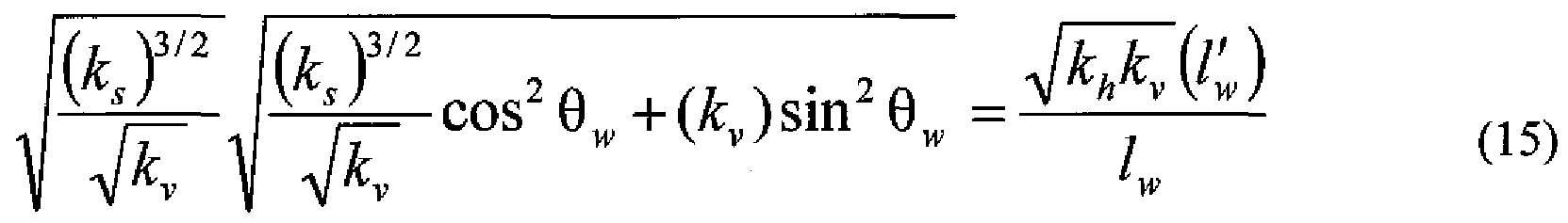
- V A v (U is explicitly given in terms of l w and kf/k v as the following.
- O Uft)TM 526 +( ⁇ v )sin 2 ⁇ w (H)
- Eq. (11) can be rearranged as the following.
- Eqs. (12) and (13) may be solved by applying the method of substitution to determine individual values of kfo and k v from Eqs. (12) and (13) as the following.
- Raphson procedure may be used to determine the positive root of Eq. (17) for k v . Once k v is determined, either Eq.
- (12) or (13) may be used to solve for kfr.
- a nonlinear equation in terms of kfr may also be obtained as the following.
- Raphson procedure as is known to those skilled in the art may be used to determine the positive root(s) of Eq. (21) for kfj. Once k ⁇ is determined, either
- Eq. (12) or (13) may be used to solve for k v .
- Either Eq. (17) or Eq. (21) may be preferred. Here, Eq. (21) was chosen.
- Eq. (22) may be rearranged as the following.
- Eq. (23) is a cubic equation, where existing analytical formulas may be used to compute the roots of the cubic equation.
- a well may be determined to be vertical or horizontal within a tolerance of approximately 10 degrees.
- K v is computed using the computed Kf 1 value and the k s value estimated from spherical slope m sp .
- Eqs. (31) and (32) indicate that OC is always negative, while ⁇ is always positive. Substituting Eqs. (31) and (32) into Eq. (30) results in the following.
- Eq. (33) is known as a "depressed" cubic equation in mathematical terms.
- D may be zero, greater than zero, or less than zero.
- the imaginary roots are omitted because they are non-physical.
- the value of the real root is given by the following.
- Kf 1 and k ⁇ values are not uniquely determined.
- FIGS. 4.1, 4.2, and 4.3 depict simulated pressure profiles for thickness-independent computation of horizontal and vertical permeability in accordance with one or more embodiments.
- the "MDTLYR Test Design" program is used to simulate pressure vs. time for a constant-rate pressure test, using the parameters from Table 1.
- the drawdown period (i.e., 0-4 hours) and buildup period ⁇ i.e., 4-8 hours) are each 4 hours as indicated by the flow rate curve (403-1).
- the simulated packer interval pressure curve (401-1) and probe pressure curve (402-1) are plotted using logarithmic scales in FIG. 4, 1 as the pressure change from the initial reservoir pressure of SOOOpsi.
- Table 1 Formation and fluid properties for mobility examples.
- FIG. 4.2 shows the buildup portions of the packer interval pressure curve
- FIG. 4.3 shows the buildup portion of the probe pressure curve (402-1) plotted using spherical superposition time scale tfa as defined by Eq. (6) above to generate the spherical flow plot (402-4).
- a straight line (404-2) is fitted to the spherical flow plot (402-4) using spherical flow straight-line analysis, known to those skilled in the art, to obtain the straight-line slope TYl sp ⁇ i.e., spherical flow
- the spherical flow slope Wl S p is estimated as -4.91
- k v is computed as 2.4 md using Eq. (18) above.
- the kfr and k v values agree very well with the input values shown in Table 1.
- Kf 1 may be estimated solely from the spherical flow equation using observation probe pressure data.
- FIGS. 5.1, 5.2, and 5.3 depict example pressure profiles for thickness-independent computation of horizontal and vertical permeability based on field data.
- the example involves a packer probe in a drilled vertical well in a carbonate formation.
- viscosity is 2.3 cp
- total compressibility is le-5 1/psi
- porosity is 0.21.
- FIG. 5.1 which is drawn separately as FIGS. 5.1.1 and 5.1.2, shows the packer pressure curve (501-1) and the probe pressure curve (502-1), respectively.
- the flow period (i.e., drawdown period) identified by the flow rate curve (503-1) is approximately 1.3 hours (4680 sec.) and the build-up period is approximately 1.9 hours (6840 sec).
- FIG. 5.2 shows the buildup portions of the packer interval pressure curve (501-1) and probe pressure curve (502-1) plotted using log/log scales as packer interval pressure curve for buildup (501-2) and probe pressure curve for buildup (502-2). Further, time derivatives for both packer interval pressure and probe pressure in the buildup period are plotted as (501-3) and (502-3), respectively. As shown, a spherical flow regime is observed/detected between 0,3 hour to 0.8 hour based on a minus half slope line (504-1) fitted to the packer interval pressure derivative curve (501-3) and/or the probe pressure derivative curve (502-3).
- FIG. 5.3 shows the buildup portion of the probe pressure curve (502-1) plotted using spherical superposition time scale tfc as defined by Eq. (6) above to generate the spherical flow plot (502-4).
- a straight line (504-2) is fitted to the spherical flow plot (502-4) using spherical flow straight-line analysis, known to those skilled in the art, to obtain the straight-line slope 7 ⁇ l sp (i.e., spherical flow
- the spherical flow slope Tii S p is estimated as -1.33
- a computer system includes one or more processor(s) (602) such as a central processing unit (CPU) or other hardware processor, associated memory (604) (e.g., random access memory (RAM), cache memory, flash memory, etc.), a storage device (606) (e.g., a hard disk, an optical drive such as a compact disk drive or digital video disk (DVD) drive, a flash memory stick, etc.), and numerous other elements and functionalities typical of today's computers (not shown).
- processor(s) such as a central processing unit (CPU) or other hardware processor
- associated memory e.g., random access memory (RAM), cache memory, flash memory, etc.
- storage device e.g., a hard disk, an optical drive such as a compact disk drive or digital video disk (DVD) drive, a flash memory stick, etc.
- numerous other elements and functionalities typical of today's computers not shown.
- the computer (600) may also include input means, such as a keyboard (608), a mouse (610), or a microphone (not shown). Further, the computer (600) may include output means, such as a monitor (612) (e.g., a liquid crystal display LCD, a plasma display, or cathode ray tube (CRT) monitor).
- a monitor e.g., a liquid crystal display LCD, a plasma display, or cathode ray tube (CRT) monitor.
- the computer system (600) may be connected to a network (614) (e.g., a local area network (LAN), a wide area network (WAN) such as the Internet, or any other similar type of network) via a network interface connection (not shown).
- a network e.g., a local area network (LAN), a wide area network (WAN) such as the Internet, or any other similar type of network
- the computer system (600) includes at least the minimal processing, input, and/or output means necessary to practice one or more embodiments.
- one or more elements of the aforementioned computer system (600) may be located at a remote location and connected to the other elements over a network.
- one or more embodiments may be implemented on a distributed system having a plurality of nodes, where each portion of the implementation (e.g., the direction tool, the servers) may be located on a different node within the distributed system.
- the node corresponds to a computer system.
- the node may correspond to a processor with associated physical memory.
- the node may alternatively correspond to a processor with shared memory and/or resources.
- software instructions to perform one or more embodiments may be stored on a computer readable medium such as a compact disc (CD), a diskette, a tape, or any other computer readable storage device.
- the systems and methods provided relate to the acquisition of hydrocarbons from an oilfield. It will be appreciated that the same systems and methods may be used for performing subsurface operations, such as mining, water retrieval and acquisition of other underground fluids or other geomaterials from other fields. Further, portions of the systems and methods may be implemented as software, hardware, firmware, or combinations thereof. While thickness-independent computation of horizontal and vertical permeability has been described with respect to a limited number of embodiments, those skilled in the art, having benefit of this disclosure, will appreciate that other embodiments may be devised which do not depart from the scope of thickness-independent computation of horizontal and vertical permeability as disclosed herein. Accordingly, the scope of thickness- independent computation of horizontal and vertical permeability should be limited only by the attached claims.
Landscapes
- Life Sciences & Earth Sciences (AREA)
- Engineering & Computer Science (AREA)
- Geology (AREA)
- Mining & Mineral Resources (AREA)
- Chemical & Material Sciences (AREA)
- Analytical Chemistry (AREA)
- Physics & Mathematics (AREA)
- Environmental & Geological Engineering (AREA)
- Fluid Mechanics (AREA)
- General Life Sciences & Earth Sciences (AREA)
- Geochemistry & Mineralogy (AREA)
- Investigation Of Foundation Soil And Reinforcement Of Foundation Soil By Compacting Or Drainage (AREA)
Abstract
Description


Claims


Priority Applications (1)
| Application Number | Priority Date | Filing Date | Title |
|---|---|---|---|
| BRPI1014895A BRPI1014895A2 (en) | 2009-04-24 | 2010-04-19 | method for determining permeability of a reservoir using a packer probe formation test tool, system for determining permeability of a reservoir using a packer probe formation test tool, and computer readable storage storing instructions for determining permeability of a reservoir using a packer probe formation test tool. |
Applications Claiming Priority (4)
| Application Number | Priority Date | Filing Date | Title |
|---|---|---|---|
| US17237809P | 2009-04-24 | 2009-04-24 | |
| US61/172,378 | 2009-04-24 | ||
| US12/758,398 US8473214B2 (en) | 2009-04-24 | 2010-04-12 | Thickness-independent computation of horizontal and vertical permeability |
| US12/758,398 | 2010-04-12 |
Publications (1)
| Publication Number | Publication Date |
|---|---|
| WO2010123789A1 true WO2010123789A1 (en) | 2010-10-28 |
Family
ID=42992864
Family Applications (1)
| Application Number | Title | Priority Date | Filing Date |
|---|---|---|---|
| PCT/US2010/031538 WO2010123789A1 (en) | 2009-04-24 | 2010-04-19 | Thickness-independent computation of horizontal and vertical permeability |
Country Status (3)
| Country | Link |
|---|---|
| US (1) | US8473214B2 (en) |
| BR (1) | BRPI1014895A2 (en) |
| WO (1) | WO2010123789A1 (en) |
Cited By (1)
| Publication number | Priority date | Publication date | Assignee | Title |
|---|---|---|---|---|
| CN112798503A (en) * | 2021-04-19 | 2021-05-14 | 中南大学 | Permeameter |
Families Citing this family (10)
| Publication number | Priority date | Publication date | Assignee | Title |
|---|---|---|---|---|
| US8826977B2 (en) * | 2009-08-18 | 2014-09-09 | Baker Hughes Incorporated | Remediation of relative permeability blocking using electro-osmosis |
| US20120179379A1 (en) * | 2011-01-10 | 2012-07-12 | Saudi Arabian Oil Company | Flow Profile Modeling for Wells |
| US10370965B2 (en) * | 2012-02-13 | 2019-08-06 | Schlumberger Technology Corporation | Method for determining a permeability or mobility of a radial flow response of a reservoir |
| WO2014120323A1 (en) * | 2013-01-31 | 2014-08-07 | Schlumberger Canada Limited | Methods for analyzing formation tester pretest data |
| US9353620B2 (en) * | 2013-03-11 | 2016-05-31 | Schlumberger Technology Corporation | Detection of permeability anisotropy in the horizontal plane |
| US9714570B2 (en) | 2013-07-03 | 2017-07-25 | Schlumberger Technology Corporation | Packer-packer vertical interference testing |
| US9347299B2 (en) | 2013-12-20 | 2016-05-24 | Schlumberger Technology Corporation | Packer tool including multiple ports |
| US9422811B2 (en) | 2013-12-20 | 2016-08-23 | Schlumberger Technology Corporation | Packer tool including multiple port configurations |
| FR3034191B1 (en) * | 2015-03-23 | 2019-08-23 | Services Petroliers Schlumberger | DETERMINATION OF TRAINING PRESSURE |
| CN111443024B (en) * | 2020-04-01 | 2021-04-13 | 清华大学 | System and method for underground measurement of rock in-situ permeability |
Citations (6)
| Publication number | Priority date | Publication date | Assignee | Title |
|---|---|---|---|---|
| US4890487A (en) * | 1987-04-07 | 1990-01-02 | Schlumberger Technology Corporation | Method for determining horizontal and/or vertical permeability of a subsurface earth formation |
| US5247830A (en) * | 1991-09-17 | 1993-09-28 | Schlumberger Technology Corporation | Method for determining hydraulic properties of formations surrounding a borehole |
| US5602334A (en) * | 1994-06-17 | 1997-02-11 | Halliburton Company | Wireline formation testing for low permeability formations utilizing pressure transients |
| US20060042370A1 (en) * | 2004-08-26 | 2006-03-02 | Baker Hughes Incorporated | Determination of correct horizontal and vertical permeabilities in a deviated well |
| US20060241867A1 (en) * | 2005-04-26 | 2006-10-26 | Fikri Kuchuk | System and methods of characterizing a hydrocarbon reservoir |
| US7290443B2 (en) * | 2002-09-09 | 2007-11-06 | Schlumberger Technology Corporation | Method for measuring formation properties with a time-limited formation test |
Family Cites Families (3)
| Publication number | Priority date | Publication date | Assignee | Title |
|---|---|---|---|---|
| US7031841B2 (en) * | 2004-01-30 | 2006-04-18 | Schlumberger Technology Corporation | Method for determining pressure of earth formations |
| GB2419424B (en) * | 2004-10-22 | 2007-03-28 | Schlumberger Holdings | Method and system for estimating the amount of supercharging in a formation |
| US8078403B2 (en) * | 2007-11-21 | 2011-12-13 | Schlumberger Technology Corporation | Determining permeability using formation testing data |
-
2010
- 2010-04-12 US US12/758,398 patent/US8473214B2/en active Active
- 2010-04-19 WO PCT/US2010/031538 patent/WO2010123789A1/en active Application Filing
- 2010-04-19 BR BRPI1014895A patent/BRPI1014895A2/en not_active IP Right Cessation
Patent Citations (6)
| Publication number | Priority date | Publication date | Assignee | Title |
|---|---|---|---|---|
| US4890487A (en) * | 1987-04-07 | 1990-01-02 | Schlumberger Technology Corporation | Method for determining horizontal and/or vertical permeability of a subsurface earth formation |
| US5247830A (en) * | 1991-09-17 | 1993-09-28 | Schlumberger Technology Corporation | Method for determining hydraulic properties of formations surrounding a borehole |
| US5602334A (en) * | 1994-06-17 | 1997-02-11 | Halliburton Company | Wireline formation testing for low permeability formations utilizing pressure transients |
| US7290443B2 (en) * | 2002-09-09 | 2007-11-06 | Schlumberger Technology Corporation | Method for measuring formation properties with a time-limited formation test |
| US20060042370A1 (en) * | 2004-08-26 | 2006-03-02 | Baker Hughes Incorporated | Determination of correct horizontal and vertical permeabilities in a deviated well |
| US20060241867A1 (en) * | 2005-04-26 | 2006-10-26 | Fikri Kuchuk | System and methods of characterizing a hydrocarbon reservoir |
Cited By (1)
| Publication number | Priority date | Publication date | Assignee | Title |
|---|---|---|---|---|
| CN112798503A (en) * | 2021-04-19 | 2021-05-14 | 中南大学 | Permeameter |
Also Published As
| Publication number | Publication date |
|---|---|
| US20100274490A1 (en) | 2010-10-28 |
| BRPI1014895A2 (en) | 2016-04-19 |
| US8473214B2 (en) | 2013-06-25 |
Similar Documents
| Publication | Publication Date | Title |
|---|---|---|
| US8473214B2 (en) | Thickness-independent computation of horizontal and vertical permeability | |
| US9864353B2 (en) | Flow balancing for a well | |
| US8599643B2 (en) | Joint structural dip removal | |
| US7890264B2 (en) | Waterflooding analysis in a subterranean formation | |
| EP2464824B1 (en) | Reservoir architecture and connectivity analysis | |
| US8567526B2 (en) | Wellbore steering based on rock stress direction | |
| US10557333B2 (en) | Estimating measures of formation flow capacity and phase mobility from pressure transient data under segregated oil and water flow conditions | |
| US8245795B2 (en) | Phase wellbore steering | |
| US20160063150A1 (en) | Enhanced oil recovery using digital core sample | |
| Tobola et al. | Determination of Reservoir Permeabiiity From Repeated induction Logging | |
| US8120357B2 (en) | Method and system for fluid characterization of a reservoir | |
| EP3245384A1 (en) | Measuring inter-reservoir cross flow rate between adjacent reservoir layers form transient pressure tests | |
| Strickland et al. | Practical aspects of reserve determinations for shale gas | |
| Gupta et al. | Haynesville shale: predicting long-term production and residual analysis to identify well interference and fracture hits | |
| Alpak et al. | Compositional modeling of oil-based mud-filtrate cleanup during wireline formation tester sampling | |
| Williams-Kovacs et al. | Analysis of multi-well and stage-by-stage flowback from multi-fractured horizontal wells | |
| Shchipanov et al. | Step rate test as a way to understand well performance in fractured carbonates | |
| Jackson et al. | An integrated approach to interval pressure transient test analysis using analytical and numerical methods | |
| US11320565B2 (en) | Petrophysical field evaluation using self-organized map | |
| Hadibeik et al. | Petrophysical properties of unconventional low-mobility reservoirs (shale gas and heavy oil) by using newly developed adaptive testing approach | |
| Gulrajani et al. | Pressure-history inversion for interpretation of fracture treatments | |
| Sharma et al. | A Workflow to Model Performance of Low Permeability Reservoirs for Devising Most Optimal Development Strategy Using Rate Transient Analysis and Single Well Modeling | |
| Akuanyionwu et al. | Examination of hydraulic fracture production modeling techniques | |
| US20230205948A1 (en) | Machine learning assisted completion design for new wells | |
| Wu et al. | Reservoir Characterization through Automatic History Matching of Underbalanced Drilling (UBD) Data in a Horizontal Well |
Legal Events
| Date | Code | Title | Description |
|---|---|---|---|
| 121 | Ep: the epo has been informed by wipo that ep was designated in this application |
Ref document number: 10767567 Country of ref document: EP Kind code of ref document: A1 |
|
| NENP | Non-entry into the national phase |
Ref country code: DE |
|
| 122 | Ep: pct application non-entry in european phase |
Ref document number: 10767567 Country of ref document: EP Kind code of ref document: A1 |
|
| REG | Reference to national code |
Ref country code: BR Ref legal event code: B01A Ref document number: PI1014895 Country of ref document: BR |
|
| ENP | Entry into the national phase |
Ref document number: PI1014895 Country of ref document: BR Kind code of ref document: A2 Effective date: 20111024 |