WO2010122876A1 - Base station apparatus, terminal apparatus, wireless communication system, transmission method, reception method, and program - Google Patents
Base station apparatus, terminal apparatus, wireless communication system, transmission method, reception method, and program Download PDFInfo
- Publication number
- WO2010122876A1 WO2010122876A1 PCT/JP2010/055595 JP2010055595W WO2010122876A1 WO 2010122876 A1 WO2010122876 A1 WO 2010122876A1 JP 2010055595 W JP2010055595 W JP 2010055595W WO 2010122876 A1 WO2010122876 A1 WO 2010122876A1
- Authority
- WO
- WIPO (PCT)
- Prior art keywords
- base station
- power
- reference signal
- transmission symbol
- data signal
- Prior art date
Links
Images


Classifications
-
- H—ELECTRICITY
- H04—ELECTRIC COMMUNICATION TECHNIQUE
- H04B—TRANSMISSION
- H04B7/00—Radio transmission systems, i.e. using radiation field
- H04B7/02—Diversity systems; Multi-antenna system, i.e. transmission or reception using multiple antennas
- H04B7/022—Site diversity; Macro-diversity
- H04B7/024—Co-operative use of antennas of several sites, e.g. in co-ordinated multipoint or co-operative multiple-input multiple-output [MIMO] systems
-
- H—ELECTRICITY
- H04—ELECTRIC COMMUNICATION TECHNIQUE
- H04J—MULTIPLEX COMMUNICATION
- H04J11/00—Orthogonal multiplex systems, e.g. using WALSH codes
- H04J11/0023—Interference mitigation or co-ordination
- H04J11/005—Interference mitigation or co-ordination of intercell interference
- H04J11/0053—Interference mitigation or co-ordination of intercell interference using co-ordinated multipoint transmission/reception
-
- H—ELECTRICITY
- H04—ELECTRIC COMMUNICATION TECHNIQUE
- H04W—WIRELESS COMMUNICATION NETWORKS
- H04W52/00—Power management, e.g. TPC [Transmission Power Control], power saving or power classes
- H04W52/04—TPC
- H04W52/06—TPC algorithms
- H04W52/16—Deriving transmission power values from another channel
-
- H—ELECTRICITY
- H04—ELECTRIC COMMUNICATION TECHNIQUE
- H04W—WIRELESS COMMUNICATION NETWORKS
- H04W52/00—Power management, e.g. TPC [Transmission Power Control], power saving or power classes
- H04W52/04—TPC
- H04W52/38—TPC being performed in particular situations
- H04W52/42—TPC being performed in particular situations in systems with time, space, frequency or polarisation diversity
Definitions
- the present invention relates to a multicarrier communication technique using a wireless communication technique, and more particularly to a power allocation technique and a notification technique thereof when performing cooperative communication using a plurality of base stations.
- Evolved Universal Terrestrial Radio Access Currently evolved third generation radio access (Evolved Universal Terrestrial Radio Access, hereinafter referred to as “EUTRA”) and evolved third generation radio access network (hereinafter referred to as Evolved Universal Terrestrial Radio Access, hereinafter referred to as “Evolved Universal Radio Access,” hereinafter referred to as “Evolved Universal Radio Access,” hereinafter referred to as “Evolved Universal Terrestrial Radio Access”). ) Is being considered. These are also referred to as Long Term Evolution (LTE). In addition, an advanced long term evolution (LTE-A: Long Term Evolution-Advanced) is being studied as an advanced form.
- LTE Long Term Evolution
- LTE-A Long Term Evolution-Advanced
- An OFDMA (Orthogonal Frequency Division Multiplexing Access) scheme is used for the downlink of LTE and LTE-A.
- the downlink radio channel in the OFDMA scheme uses resources of the frequency axis (subcarrier) and time axis (OFDM symbol) of the OFDM signal, and uses time division multiplexing TDM (Time Division Multiplexing), frequency division multiplexing FDM (Frequency Division Multiplexing). ), Or a combination of TDM and FDM, multiplexed in time and frequency.
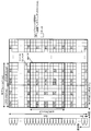
- FIG. 6 is a configuration example of a downlink radio frame of EUTRA proposed in 3GPP, and is a diagram illustrating an example of radio channel mapping in four transmission antennas.
- the downlink radio frame shown in FIG. 6 is composed of a plurality of subcarriers on the frequency axis (vertical axis) and is composed of a frequency bandwidth Bch and a symbol on the time axis (horizontal axis).
- one slot consists of seven symbols, and two slots constitute one subframe.
- a two-dimensional radio resource block is configured by 12 subcarriers ⁇ 7 symbols, and a resource block pair (RB pair) surrounded by a thick line in FIG. 6 is formed by two radio resource blocks continuous on the time axis. It is configured.
- a plurality of resource block pairs (RB pairs) are collected to form a radio frame.
- a minimum unit composed of one subcarrier and one OFDM symbol is referred to as a resource element.
- the entire downlink spectrum (base station-specific system frequency bandwidth Bch) is 20 MHz, one radio frame is 10 ms, and the subframe SF is 1 ms.
- a resource block pair (RB pair) is composed of one subcarrier and one subframe (1 ms).
- the subcarrier frequency bandwidth Bsc is 15 kHz
- the frequency bandwidth Bch of the resource block is 180 kHz (15 kHz ⁇ 12)
- 1200 subcarriers are included in the entire 20 MHz band in the downlink.
- the radio frame includes 100 RBs.
- the first, fifth, eighth, and twelfth OFDM symbols are collectively referred to as the reference (reference) signal RS1 of the first antenna (Ant1) and the second antenna (Ant2). It can be seen that the reference signal RS2 is included. Also, the third antenna reference signal RS3 and the fourth antenna reference signal RS4 are similarly arranged in the second and ninth OFDM symbols.
- data is multiplexed and transmitted from each transmission antenna. The radio channel mapping in the two transmission antennas is obtained by removing the reference signal RS3 of the third antenna and the reference signal RS4 of the fourth antenna in FIG. 6, and data is transmitted instead.
- the radio channel mapping in one transmission antenna is obtained by removing the reference signal RS2 of the second antenna, the reference signal RS3 of the third antenna, and the reference signal RS4 of the fourth antenna in FIG. Data is sent. (See Non-Patent Document 1 below).
- a terminal apparatus demodulates a data signal based on a reference signal.
- the power of the data signal can be obtained from the ratio ⁇ A between the data signal and the reference signal and the power of the reference signal received by the terminal device, which are individually notified from the base station device for each terminal device.
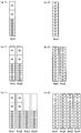
- FIG. 7 is a diagram showing the value of ⁇ A defined by EUTRA (see Non-Patent Document 2 below).
- the power of the data signal (referred to as type B) in the OFDM symbol that transmits the reference signal is different from that of the data signal (referred to as type A) in the OFDM symbol that does not transmit the reference signal. It is supposed to be.
- the power excluding the power of the reference signal is used as the power of the data signal (type B) to maintain the power balance between symbols (see Non-Patent Document 3 below). Note that the value of ⁇ A in FIG. 7 described above is the ratio between the type A data signal and the reference signal.
- FIG. 10 is a diagram showing such a concept.
- A-1) in FIG. 10 is a diagram schematically showing the power distribution of the reference signal and the data signal in the fifth OFDM symbol, which is the OFDM symbol in which the reference signal in one transmission antenna exists.
- (a-2) is a diagram schematically showing the power distribution of the reference signal and the data signal in the sixth OFDM symbol, which is an OFDM symbol in which no reference signal exists.
- two reference signals and 10 data signals are arranged in the fifth OFDM symbol
- 12 data signals are arranged in the sixth OFDM symbol.
- (b-1) schematically represents the power distribution of the reference signal and the data signal in the fifth OFDM symbol, which is the OFDM symbol in which the reference signal exists in the two transmission antennas, for each transmission antenna.
- (b-2) is a diagram schematically showing the power distribution of the reference signal and the data signal in the sixth OFDM symbol, which is an OFDM symbol in which no reference signal exists, for each transmission antenna.
- two reference signals for each transmit antenna and eight data signals are arranged in the fifth OFDM symbol
- twelve data signals are arranged in the sixth OFDM symbol.
- (c-1) is a diagram schematically showing the power distribution of the reference signal and the data signal in the fifth OFDM symbol, which is an OFDM symbol in which reference signals in the four transmission antennas exist, for each transmission antenna.
- (c-2) is a diagram schematically showing the power distribution of the reference signal and the data signal in the sixth OFDM symbol, which is an OFDM symbol in which no reference signal exists, for each transmission antenna. With 4 transmit antennas, 2 reference signals for each transmit antenna and 8 data signals are arranged in the 5th OFDM symbol, and 12 data signals are arranged in the 6th OFDM symbol.
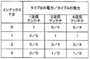
- Non-Patent Document 2 the value of FIG. 11 is determined as the ratio of the data power of type B and type A for each number of transmission antennas of the base station. Will be notified. This value is determined for each base station apparatus in EUTRA, and the same value is used for all terminal apparatuses that communicate with the same base station apparatus.
- FIG. 8 is a diagram illustrating an LTE channel configuration example.
- the downlink of LTE (communication from the base station apparatus BS to the terminal apparatus UE) includes a downlink control area designation channel (PCFICH: Physical Control Format Channel) and a downlink complex retransmission request channel (PHICH: Physical Hybrid ARQ Indicator).
- PCFICH Physical Control Format Channel
- PHICH Physical Hybrid ARQ Indicator
- PMCH Physical Multicast Channel
- PDSCH Physical Downlink Shared Channel
- PDCCH Physical Downlink Control Channel
- radcast Channel Physical Downlink Control Channel
- SCH Synchronization Channel
- RS Reference Signal
- the uplink of LTE (communication from the terminal device UE to the base station device BS) includes a random access channel (RACH: Random Access Channel), an uplink shared channel (PUSCH: Physical Uplink Shared Channel), and uplink control. It is comprised by the channel (PUCCH: Physical Uplink Control Channel).
- RACH Random Access Channel
- PUSCH Physical Uplink Shared Channel
- PUCCH Physical Uplink Control Channel
- a reference signal (RS: Reference Signal) used as a reference when measuring signal quality and demodulating a received signal is also transmitted from the terminal apparatus UE to the base station apparatus BS.
- RS Reference Signal
- Coordinated multi-base station communication by transmitting signals from a plurality of base station devices, to obtain an improvement in reception quality due to the transmission diversity effect,
- the transmission capacity is increased by the spatial multiplexing effect.
- signals are simultaneously transmitted from a plurality of base station devices, and the terminal device receives signals from the plurality of base station devices.
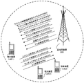
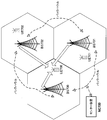
- FIG. 9 is a diagram showing an outline of the cooperative multiple base station communication method.
- the terminal apparatus UE700 present at the cell edge also receives signals from the neighboring base station apparatuses BS701 and BS702 at the same time.
- the terminal device UE700 When the distance between the terminal device UE700 and the base station device BS700 is long, generally the reception characteristics deteriorate. By receiving signals from other base station apparatuses BS701 and BS702 at the same time, deterioration of characteristics is suppressed. Similarly, the terminal device UE701 communicates with the main base station device BS701, but does not perform cooperative reception because the distance is short. Depending on the position of the terminal apparatus UE, the position and number of base station apparatuses used for multiple cooperative communication are adaptively changed. The base station apparatuses are connected by a communication line called a backhaul.
- the data to be transmitted to the terminal device UE700 includes data transmitted from the base station device 700 and data transmitted from the BS 701 through the backhaul.
- the backhaul may be a wired line or a wireless line.
- a wireless line there are an in-band method using the same frequency band as that used during signal communication and an out-of-band method using a frequency band different from the band used during signal communication.
- each base station device controls the cooperation between the base station devices.
- the cooperation between the base station devices is controlled by the center device NC700 connected to the backhaul, or each base station device also has the function of the center device, and each base station device while coordinating in the communication between the base station devices. Is performed by independent control.
- htm 3GPP TS 36.213, V8.5.0 (2008-12), Technical Specification Group Radio Access Network; Evolved Universal Terrestrial Radio Access (E-TR) (E-TR). http: // www. 3 gpp. org / ftp / Specs / html-info / 36213. htm 3GPP TS 36.814, V1.0.0 (2009-02), 3rd Generation Partnership Project; Technical Specification Group Radio Access Network 9: FurtherAdvanceTrump
- the received power at the terminal device is a combination of signals received from base station devices that perform cooperative multi-base station communication.
- FIG. 12 shows a reference signal R, a type A data signal Da, and a type B data signal Db in the case where cooperative base station communication is performed using two base station apparatuses (base station apparatus 1 and base station apparatus 2). It is a schematic diagram showing electric power. The vertical direction represents power.
- the numbers after R, Da, and Db are base station device numbers, that is, number 1 represents a signal from the base station device 1, and number 2 represents a signal from the base station device 2.
- (A-1) and (a-2) are the transmission signal powers from the base station apparatus 1 and the base station apparatus 2, respectively, and (b-1) and (b-2) are the base station apparatus 1 and And the power after the transmission signal from the base station apparatus 2 receives attenuation
- damping of a propagation path is represented.
- the amount of attenuation differs for each base station apparatus depending on the propagation distance and state from each base station apparatus to the terminal apparatus.
- (C) is a composite signal from each base station apparatus received by the terminal apparatus.
- the power of the reference signal in both base station apparatuses is as follows.
- Base station apparatus 1 P (R1)
- Base station device 2 P (R2) Further, if the ratio ⁇ A between the type A data signal and the reference signal is the same value, the following setting is made.
- the type B transmission signal power is set as follows.
- Reference signal power P ′ (R2) P (R2) ⁇ k2
- a data power P ′ (Da2) P (R2) ⁇ ⁇ A ⁇ k2
- Type B data power P ′ (Db2) P (R2) ⁇ ⁇ A ⁇ ⁇ B ⁇ k2 Since the signal received by the terminal device is a composite signal of these, it is as follows.
- Reference signal power P ′′ (R) P (R1) ⁇ k1 + P (R2) ⁇ k2
- the value of ⁇ B is a value determined for each base station apparatus.
- the value of ⁇ B is semi-fixed in consideration of the number of antennas of the base station apparatus, cell radius, reference signal power, and the like.
- the values of ⁇ B are not necessarily equal between base station apparatuses performing multiple base station communication.
- the signals received by the terminal apparatus are as follows.
- the present invention has been made in view of such circumstances, and an object of the present invention is to provide a technique capable of correctly deriving the power of a data signal of a received signal when performing a plurality of base station communications. .
- a base station apparatus that communicates with a terminal apparatus alone or in cooperation with another base station apparatus, the means for setting whether or not to perform the coordinated communication, and the cooperation Means for determining a ratio between the power of the data signal in the transmission symbol including the reference signal and the power of the data signal in the transmission symbol not including the reference signal, depending on whether communication is performed or not.
- a base station apparatus is provided. It is preferable to include means for transmitting information indicating the ratio of the power of the data signal in the transmission symbol including the reference signal and the power of the data signal in the transmission symbol not including the reference signal to the terminal apparatus.
- the present invention is a terminal apparatus that communicates with a base station apparatus that cooperates with another base station apparatus, and the power of a data signal in a transmission symbol including a reference signal and the data in a transmission symbol that does not include the reference signal
- a terminal device comprising means for receiving information indicating a ratio of signal power to the base station device.
- a wireless communication system that performs coordinated multi-base station communication between a plurality of base station apparatuses and terminal apparatuses, wherein communication is performed using a transmission symbol that includes a reference signal and a transmission symbol that does not include a reference signal.
- the transmitting device of the base station device at least means for communicating with the network between base station devices of the wireless communication system, means for setting whether to implement the cooperative multiple base station communication, Means for determining a power of the data signal in the transmission symbol including the reference signal and a power ratio of the data signal in the transmission symbol not including the reference signal; a power of the data signal in the transmission symbol including the reference signal; Means for transmitting each of the information on the power of the data signal in the transmission symbol not including the reference signal, and
- the means for determining the power ratio of the data signal in the transmission symbol including the reference signal and the data signal in the transmission symbol not including the reference signal includes the power ratio setting when the cooperative multi-base station communication is not performed, and the cooperation Wireless communication characterized in that it is a
- the wireless communication system includes power of a data signal in a transmission symbol including the reference signal and a reference signal between base station apparatuses that perform the cooperative multiple base station communication when performing cooperative multiple base station communication. It is preferable to set the ratio to the power of the data signal in the non-transmitted symbols to the same value.
- the base station apparatus includes a power of a data signal in a transmission symbol including the reference signal and a reference signal between base stations performing the coordinated multi-base station communication. It is preferable to set the ratio of the power of the data signal in a transmission symbol that does not exist to the same value, and notify the terminal device of the ratio of the power of the data signal and the power of the reference signal in a transmission symbol that does not include the reference signal.
- the base station apparatus individually notifies the terminal apparatus of a power ratio setting when the cooperative multiple base station communication is not performed and a power ratio setting when the cooperative multiple base station communication is performed. .
- the present invention is a wireless communication system that performs coordinated multiple base station communication between a plurality of base station apparatuses and terminal apparatuses, and includes a transmission symbol including a reference signal and a transmission symbol not including a reference signal.
- a base station apparatus in a multi-carrier communication system that performs communication using the base station apparatus, wherein the transmission apparatus of the base station apparatus communicates with at least a network between base station apparatuses of the wireless communication system, and the coordinated multiple base station communication Means for determining whether or not to implement, a means for determining a ratio between the power of the data signal in the transmission symbol including the reference signal and the power of the data signal in the transmission symbol not including the reference signal, and the reference signal Information of the power of the data signal in the transmission symbol including the data signal power in the transmission symbol not including the reference signal And means for determining the ratio between the power of the data signal in the transmission symbol including the reference signal and the power of the data signal in the transmission symbol not including the reference signal.
- a power ratio setting when no station communication is performed and a power ratio setting when the cooperative multi-base station communication is performed are respectively performed, and the power ratio is determined depending on whether or not the cooperative multi-base station communication is performed.
- the power of the data signal in the transmission symbol including the reference signal and the data signal in the transmission symbol not including the reference signal between the base station apparatuses performing the coordinated multi-base station communication It is preferable to set the ratio of the power to the same value.
- the power of the data signal in the transmission symbol including the reference signal and the data signal in the transmission symbol not including the reference signal is set to the same value and the terminal device is notified of the ratio of the power of the data signal and the power of the reference signal in the transmission symbol not including the reference signal. It is preferable that the terminal device is individually notified of the power ratio setting when the cooperative multiple base station communication is not performed and the power ratio setting when the cooperative multiple base station communication is performed.
- the present invention is a wireless communication system that performs coordinated multiple base station communication between at least a plurality of base station apparatuses and a terminal apparatus, and includes a transmission symbol that includes a reference signal, a transmission symbol that does not include a reference signal,
- the transmission apparatus of the base station apparatus at least means for communicating with the inter-base station network of the wireless communication system, and whether or not the cooperative multiple base station communication can be performed.
- the receiving device of the terminal device includes at least means for receiving a reference signal of each base station device that performs the coordinated multiple base station communication, and means for estimating a propagation path from each base station device to the terminal device.
- It is a wireless communication system characterized by being a terminal device having means for calculating the received data power at the time.
- a wireless communication system that performs coordinated multiple base station communication between at least a plurality of base station apparatuses and a terminal apparatus, using a transmission symbol that includes a reference signal and a transmission symbol that does not include a reference signal
- the transmitting device of the base station apparatus includes at least means for communicating with an inter-base station network of the wireless communication system, and means for setting whether to perform the cooperative multi-base station communication.
- a terminal device used in a multicarrier communication system wherein the receiving device of the terminal device includes at least means for receiving a reference signal of each base station device that performs the coordinated multiple base station communication, and the terminal device from each base station device Information on the ratio between the power of the data signal in the transmission symbol including the reference signal in each base station apparatus and the power of the data signal in the transmission symbol not including the reference signal is received. Means for receiving power ratio information between the power of the reference signal in each base station apparatus and the power of the data signal in a transmission symbol not including the reference signal, and calculating received data power at the time of cooperative multi-base station communication
- the terminal device is characterized by being a terminal device having means for performing the processing.
- the present invention provides a radio communication system that performs coordinated multi-base station communication between a plurality of base station apparatuses and terminal apparatuses, using a transmission symbol that includes a reference signal and a transmission symbol that does not include a reference signal.
- a multicarrier communication method for performing communication wherein the base station device transmits to the terminal device a power of a reference signal in a transmission symbol including a reference signal at the time of single base station communication and a data signal in a transmission symbol not including a reference signal Information to the terminal device and information on the ratio between the power of the data signal in the transmission symbol including the reference signal and the power of the data signal in the transmission symbol not including the reference signal at the time of single base station communication
- the step of transmitting, and the power of the reference signal and the reference signal in the transmission symbol including the reference signal at the time of cooperative multi-base station communication when performing cooperative multi-base station communication The ratio of the power of the data signal in the transmission symbol not including the ratio, and the ratio of the power of the data signal in the transmission symbol including the reference
- the present invention provides a radio communication system that performs coordinated multi-base station communication between a plurality of base station apparatuses and terminal apparatuses, using a transmission symbol that includes a reference signal and a transmission symbol that does not include a reference signal.
- a multi-carrier communication method for performing communication wherein the terminal apparatus receives a base station-specific reference signal for each base station apparatus performing the coordinated multi-base station communication, and the received base station for each base station apparatus.
- Information on the ratio of the power of the data signal in the symbol to the transmission symbol not including the power of the data signal in the transmission symbol including the reference signal and the reference signal Receiving information on the ratio of data signal power to the base station device, the base station-specific reference signal and the calculated channel attenuation amount between the base station device and the terminal device for each base
- the present invention may be a program for causing a computer to execute the transmission / reception method described above, or a computer-readable recording medium for recording the program.
- the program may be acquired by a transmission medium such as the Internet.
- a communication system that performs multi-base station communication, in a multicarrier communication system that performs communication using a transmission symbol that includes a reference signal and a transmission symbol that does not include a reference signal, The power of the data signal can be correctly derived.
- Reception antenna 33 ... Reception RF part 34 ... A / D unit, 35 ... CP removal unit, 36 ... FFT unit, 37 ... demultiplexing unit, 38 ... propagation channel estimation unit, 39 ... propagation channel compensation unit, 40 ... multimode restoration unit, 41 ... data demodulation Part, 42 ... turbo recovery Parts, 43 ... propagation channel compensation unit, 44 ... multiplexing mode restoring unit, 45 ... QPSK demodulation unit, 46 ... convolutional decoder, 47 ... controller, 48 ... signal power determination unit, 49 ... receiving device.
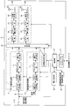
- FIG. 1 is a functional block diagram showing a configuration example of a transmission apparatus in a base station apparatus when the multicarrier communication system according to the first embodiment of the present invention is applied to two transmission antennas.
- the data to be transmitted is input to the transmission device 1.
- information on power control to be applied, and part of information are input together with data transmitted in the form of a data signal.
- These data are input to the turbo encoding unit 4 in the data signal processing unit 3.
- the turbo coding unit 4 performs error correction coding using a turbo code to increase error tolerance of input data in accordance with a coding rate instruction from the control unit (CPU) 15.
- the next-stage data modulation unit 5 includes QPSK (Quadrature Phase Shift Keying; four-phase phase shift keying), 16QAM (16 Quadrature Amplitude Modulation), 64QAM (64 Quadrature Amplitude Modulation value, etc.).
- QPSK Quadratture Phase Shift Keying; four-phase phase shift keying
- 16QAM (16 Quadrature Amplitude Modulation
- 64QAM 64 Quadrature Amplitude Modulation value, etc.
- the precoding unit 6 transmits the signal modulated by the data modulation unit 5 to each mobile station apparatus by performing phase rotation, weighting, redundancy, etc. according to the multiplexing mode instructed from the control unit 15 A signal for each transmitting antenna to be generated is generated.
- the weighting unit 7 weights the signal from the precoding unit 6 based on the power determined by the power determination unit 14 and outputs the result to the multiplexing unit 18.
- the weighting unit 7 may be included as part of the weighting function of the precoding unit 6, but will be described as a separate configuration in FIG.
- a plurality of data signal processing units 3 are provided as shown. Each processing content is the same.
- the control information is input to the convolutional code unit 9 of the control signal processing unit 8.
- the convolutional code unit 9 performs error correction coding using a convolutional code to increase the error tolerance of the input information in accordance with the coding rate instruction from the control unit 15.
- the QPSK modulation unit 10 modulates the control information that has been subjected to error correction coding by the convolutional coding unit 9 using the QPSK modulation method.
- the precoding unit 11 transmits the signal modulated by the QPSK modulation unit 10 to each mobile station apparatus by performing phase rotation, weighting, redundancy, etc. according to the multiplexing mode instructed by the control unit 15 A control signal for each transmission antenna to be generated is generated.
- the weighting unit 12 weights the signal from the precoding unit 11 based on the power determined by the power determination unit 14 and outputs the weighted signal to the multiplexing unit 18.
- the weighting unit 7 may be included as part of the weighting function of the precoding unit 6 as in the case of the data signal processing unit 3.
- the reference signal generation unit 13 generates a reference signal transmitted by each transmission antenna 23 of the transmission device 1.
- the power determination unit 14 sets powers such as a reference signal, a data signal, and a control signal, and sets values of ⁇ A and ⁇ B.
- the coordinated multi-base station communication setting unit 16 performs settings related to the coordinated multi-base station communication for the terminal device designated to perform the coordinated multi-base station communication through the backhaul interface 17.
- the backhaul interface 17 serves as an interface for communicating settings related to cooperative multi-base station communication, data exchange, and other network-related information with other base station devices and center devices through the inter-base station device network.
- the multiplexing unit 18 transmits the transmission data, control information, and reference signal output from the data signal processing unit 3, the control signal processing unit 8, and the reference signal generation unit 13 in the transmission mode indicated by the control unit 15. Accordingly, the allocation to the resource element is determined, a signal for each antenna is generated, and the signal is sent to the OFDM transmitter 24 of each antenna.
- Each OFDM transmitter 24 (in the figure, two OFDM transmitters 24 are provided corresponding to two antennas 23), in order from the input side, respectively, IFFT (Inverse Fourier Transform) unit 19, CP insertion unit 20, a D / A unit 21, a transmission RF unit 22, and a transmission antenna 23.
- IFFT Inverse Fourier Transform
- CP insertion unit 20 a D / A unit 21, a transmission RF unit 22, and a transmission antenna 23.
- the functions of the plurality of OFDM transmitters 24 are the same.
- the IFFT unit 19 performs fast inverse Fourier transform on the signal input from the multiplexing unit 18 to perform OFDM modulation.
- the CP insertion unit 20 generates a symbol in the OFDM scheme by adding a cyclic prefix (CP) to the OFDM-modulated signal.
- the cyclic prefix can be obtained by a known method for duplicating a part of the beginning or end of a symbol to be transmitted.
- the D / A unit 21 D / A converts the baseband digital signal input from the CP insertion unit 20 into an analog signal.
- the transmission RF unit 22 generates an in-phase component and a quadrature component of the intermediate frequency from the analog signal input from the D / A unit 21, removes an extra frequency component with respect to the intermediate frequency band, and converts the intermediate frequency signal to a high frequency.
- the signal is converted (up-converted) into the above signal, excess frequency components are removed, power amplification is performed, and the signal is output to the transmission antenna 23.
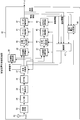
- FIG. 2 is a functional block diagram showing a configuration example of the receiving device of the terminal device of the multicarrier communication device according to the embodiment of the present invention.
- the reception processing unit 49 of the receiving apparatus according to the present embodiment includes an antenna 32, a reception RF unit 33, an A / D unit 34, a CP removal unit 35, an FFT unit 36, and a multiplexing unit.
- the reception RF unit 33 amplifies the signal received via the reception antenna 32, converts it to an intermediate frequency (down-conversion), removes unnecessary frequency components, and sets the amplification level so that the signal level is properly maintained. Control and perform quadrature demodulation based on the in-phase and quadrature components of the received signal.
- the A / D unit 34 converts the analog signal orthogonally demodulated by the reception RF unit 33 into a digital signal.
- the CP removing unit 35 removes a portion corresponding to a cyclic prefix from the digital signal output from the A / D unit 34.
- the FFT unit 36 performs fast Fourier transform on the signal input from the CP removal unit 35 and performs demodulation of the OFDM method.
- the propagation path compensation unit 39 to the turbo decoding unit 42 are used for data signal demodulation processing, and the propagation path compensation unit 43 to the convolutional decoding unit 46 are used for control information signal demodulation processing.
- the demultiplexing unit 37 Based on an instruction from the control unit 47, the demultiplexing unit 37 extracts a reference signal from the signal that is FFT-transformed by the FFT unit 36, that is, a received signal demodulated by the OFDM method, from the arranged resource elements and outputs the extracted reference signal. Specifically, the demultiplexing unit 37 extracts a reference signal having a fixed arrangement and outputs the reference signal to the propagation path estimation unit 38. The demultiplexer 37 also separates the data signal and the control information signal.
- the propagation path estimation unit 38 estimates propagation path fluctuations for each of the transmission antenna 1 and the transmission antenna 2 of the transmission apparatus 1 based on the reception results of the known reference signals separated and extracted by the demultiplexing unit 37, and propagation path fluctuations Output the compensation value.
- the propagation path compensators 39 and 43 compensate the propagation path fluctuation of the input signal based on the propagation path fluctuation compensation value from the propagation path estimation section 38.
- the multimode restoration units 40 and 44 use the data power determined by the signal power determination unit 48 based on the transmission mode used by the transmission apparatus for the signals that the propagation path compensation units 39 and 43 compensate for the propagation path fluctuation. Considering this, the frequency set of each antenna of the transmission signal generated by the transmission apparatus is reproduced and combined to generate a signal before redundancy.
- the data demodulation unit 41 demodulates the data signal generated by the multiple mode restoration unit 40. This demodulation is performed corresponding to the modulation method used in the data modulation unit 5 of the transmission apparatus 1, and information on the modulation method is instructed from the control unit 47.
- the turbo decoder 42 decodes the data signal demodulated by the data demodulator 41. Notification information and broadcast information are extracted from the decoded data and input to the control unit 47. Information regarding power is input to the signal power determination unit 48.
- the QPSK demodulator 45 performs QPSK demodulation of the control information signal generated by the multimode restoration unit 44.
- the convolutional decoding unit 46 decodes the control information signal demodulated by the multimode restoration unit 44.
- the signal power determination unit 48 determines the power of the received signal from the reference signal power separated by the demultiplexing unit 37 and information included in the control information, broadcast information, and notification information.
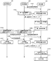
- FIG. 3 is a flowchart showing an example of the power setting method according to the first embodiment of the present invention.
- the base station apparatus 100 transmits a base station specific reference signal (L101). Note that the base station-specific reference signal is always transmitted regardless of whether the single base station communication is a coordinated multiple base station communication, regardless of the timing shown in the figure, and whether or not the terminal device exists. .
- the terminal apparatus 102 directly determines the received power of the reference signal from the received reference signal (S102).
- the base station apparatus 100 transmits ⁇ A and ⁇ B, which are power setting parameters during single base station communication, to the terminal apparatus (L102).
- the terminal device can determine the power of type A and type B data from the power of the reference signal and the received ⁇ A and ⁇ B (S103), and can demodulate and receive the data (S104).
- the terminal device when the terminal device performs cooperative multiple base station communication (CoMP), the terminal device also receives a signal from the base station device 101 used for CoMP. As described above, the base station apparatus always transmits a base station specific reference signal (L103). The terminal device also receives a base station specific reference signal from the base station device (herein referred to as a cooperative base station) 101. On the other hand, a base station specific reference signal from a conventional base station apparatus (referred to as a main base station here) is also received (L104), and the power of each reference signal is determined (S109).
- a base station specific reference signal from a conventional base station apparatus (referred to as a main base station here) is also received (L104), and the power of each reference signal is determined (S109).
- ⁇ A and ⁇ B which are power parameters, are set to the same value.
- ⁇ B is originally a setting unique to the base station as described above and cannot be changed.
- the same value is set in both base station apparatuses as a CoMP parameter, and is sent to the terminal apparatus. Notify (L106).
- the value of ⁇ B may be different from the value of ⁇ B unique to the base station at the time of single base station communication. Further, as shown in FIG.
- ⁇ B when the number of antennas of a base station that performs coordinated multi-base station communication is one transmission antenna, and the other base station apparatuses are 2 to 4 transmission antennas, ⁇ B is set.
- P_B which is an index to be expressed, is an interpretation of ⁇ B that varies depending on the number of antennas. For example, this may be an interpretation that always follows the number of antennas of the main base station device, or always one transmission antenna when performing coordinated multi-base station communication. Alternatively, it may be interpreted as a case of 2, 4 transmission antennas. In the latter case, the base station device may explicitly inform the terminal device whether or not cooperative multi-base station communication is being performed, and whether to interpret one transmission antenna or two or four transmission antennas. May be communicated explicitly.
- a new value may be defined when performing cooperative multiple base station communication.
- This power parameter notification is performed for each terminal.
- the base station that performs CoMP while sending the parameter ⁇ B for the conventional single base station communication mode.
- the parameter ⁇ B for CoMP can be sent.
- the terminal device can calculate the power of type A and type B from the received ⁇ A, ⁇ B and the power of the previous reference signal (S110), and can perform CoMP reception (S111).
- this notification is sent only from the main base station apparatus 100.
- the notification may be sent from the coordinated base station apparatus 101 or sent from both sides. You may do it.
- ⁇ B which is a setting unique to the base station apparatus
- ⁇ B which is a setting unique to the base station apparatus
- the terminal since the apparatus knows both ⁇ B, there is an advantage that the data power can be correctly determined in accordance with the switching.
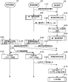
- FIG. 4 is a flowchart showing an example of power setting steps in the case where the notification of ⁇ B at the time of CoMP is not explicitly performed according to the second embodiment of this invention.
- ⁇ B at the time of CoMP is notified separately from ⁇ B at the time of reception of a single base station, but in that case, it is necessary to newly notify.
- the notification as ⁇ B is not performed. Notification is performed by changing ⁇ A, which is the power ratio between the type A and the reference signal. Since ⁇ A is originally notified for each terminal device, there is an advantage that the amount of notification does not change even when ⁇ A is changed and notified.
- the procedure for entering the CoMP mode is not described in the same way as in the first embodiment.
- the same description is omitted for receiving the reference signal from each base station apparatus.
- Base station apparatuses 100 and 101 that perform CoMP similarly adjust usage parameters and scheduling between base station apparatuses (L105), and determine CoMP parameters (S108 and S107).
- the power parameters ⁇ A and ⁇ B are set to the same values as in the first embodiment, but parameter notification is not newly performed for ⁇ B. Instead, ⁇ A is set for CoMP and notified (L206).
- the notification of ⁇ B is not newly performed, there is an advantage that the amount of signaling is not changed compared to the case of single base station communication.
- ⁇ A and ⁇ B are not notified for the CoMP mode, but the power of type A and type B is all determined in the terminal device.
- the same values ⁇ A and ⁇ B may be set for CoMP between base station apparatuses that perform CoMP in the CoMP mode, or different values may be set.
- the same ⁇ A and ⁇ B as in the case where each base station apparatus performs single base station communication may be used as they are during CoMP, or different values of ⁇ A and ⁇ B may be used during CoMP.
- each base station apparatus notifies each terminal apparatus of ⁇ A and ⁇ B.
- FIG. 5 shows a case where ⁇ B is not explicitly notified in CoMP according to the third embodiment of the present invention, and ⁇ A and ⁇ B are not set to the same value for CoMP in each base station apparatus. It is a flowchart showing an example of the step of the electric power setting of. Instead of setting ⁇ A and ⁇ B for CoMP to the same value from the base station device to the terminal device, the values of ⁇ A and ⁇ B for the main transmission base station device and the coordinated base station are notified (L306, L307). . If the values of ⁇ A and ⁇ B are the same as those at the time of single base station communication, this notification can be omitted. Further, this notification may be transmitted collectively from one base station apparatus without being individually performed from each base station apparatus.
- the terminal apparatus receives the reference signals from the base station apparatuses 100 and 101 that perform CoMP (L104, L103), and can know the power of the reference signals (S109). Further, by performing propagation path estimation from the reference signal (S310), the channel attenuation k1 between the base station apparatus 100 and the terminal apparatus 102, the channel attenuation k2 between the base station apparatus 101 and the terminal apparatus 102, and Can know.
- the received powers of the reference signals received from the main base station apparatus and the coordinated base station apparatus are P ′ (R1) and P ′ (R2), respectively, and ⁇ A of the main base station apparatus and the coordinated transmission apparatus are ⁇ A1 and ⁇ A2, respectively.
- Type A data power P ′′ (Da) P ′ (R1) ⁇ ⁇ A1 + P ′ (R2) ⁇ ⁇ A2
- Type B data power P ′′ (Db) P ′ (R1) ⁇ ⁇ A1 ⁇ ⁇ B1 + P ′ (R2) ⁇ ⁇ A2 ⁇ ⁇ B2
- the reference signal powers of the base station device 100 and the base station device 101 received by the terminal device are P ′ (R1) and P ′ (R2), respectively.
- the terminal apparatus does not have to set ⁇ A and ⁇ B for CoMP between the main base station apparatus and the coordinated base station apparatus. There is an advantage that data power can be determined correctly.
- a program for realizing the functions described in the present embodiment is recorded on a computer-readable recording medium, and the program recorded on the recording medium is read into a computer system and executed to execute processing of each unit. May be performed.
- the “computer system” here includes an OS and hardware such as peripheral devices.
- the “computer system” includes a homepage providing environment (or display environment) if a WWW system is used.
- the “computer-readable recording medium” means a storage device such as a flexible disk, a magneto-optical disk, a portable medium such as a ROM and a CD-ROM, and a hard disk incorporated in a computer system. Furthermore, the “computer-readable recording medium” dynamically holds a program for a short time like a communication line when transmitting a program via a network such as the Internet or a communication line such as a telephone line. In this case, a volatile memory in a computer system serving as a server or a client in that case is also used to hold a program for a certain period of time.
- the program may be a program for realizing a part of the above-described functions, or may be a program that can realize the above-described functions in combination with a program already recorded in a computer system.
- the present invention can be used for communication devices.
Abstract
When a terminal apparatus (102) is communicating with a base station apparatus (100) by single base station communication, that base station apparatus (100) transmits base station specific reference signals (L101). The terminal apparatus (102) determines the received power of the direct reference signals from the received reference signals (S102). The base station apparatus (100) transmits, to the terminal apparatus, power setting parameters ρA and ρB at the time of single base station communication (L102). The terminal apparatus can determine the power for type A and type B data based on the power of the reference signals from earlier and the received ρA and ρB (S103), and demodulate then receive data (S104). When the terminal apparatus is communicating by coordinated multipoint communication (CoMP), the terminal apparatus will also receive signals from a base station apparatus (101) used in CoMP. As stated earlier, base station apparatuses constantly transmit base station specific reference signals (L103). The terminal apparatus receives the base station specific reference signals from this base station apparatus (referred to here as the coordinated multipoint base station) (101), also receives the base station specific reference signals from the conventional base station apparatus (referred to here as the main base station) (L104), and determines the power of the respective reference signals (S109). The base station apparatuses (100, 101) carrying out CoMP adjust the used parameters and scheduling between each other (L105), and determine their respective CoMP parameters (S108, S107). At the time of CoMP, the same values for the parameters for CoMP are set for both base station apparatuses, and are notified to the terminal apparatus (L106). This notification is sent per terminal, and in the case of terminal apparatuses which do not perform CoMP but are under the same base station apparatus, a parameter ρB for use in the conventional single base station communication mode can be sent, while in the case of base station apparatuses performing CoMP, a parameter ρB for use in CoMP can be sent. The terminal apparatus can calculate the type A and type B power based on the power of the received ρA, ρB and the earlier reference signals (S110), and can perform CoMP reception (S111). Due to this, when carrying out coordinated multipoint communication, the terminal apparatus can correctly determine the power for the data at the time of coordinated multipoint communication in cases when the ratios of the power for the data at the transmission symbols containing the reference signals to the power for the data at the transmission symbols not containing the reference signals are different values between the base stations carrying out coordinated multipoint communication.
Description
本発明は、無線通信技術を利用したマルチキャリア通信技術に関し、特に、複数の基地局を用いて協調通信を行う際の電力割り当て技術およびその通知技術に関する。
The present invention relates to a multicarrier communication technique using a wireless communication technique, and more particularly to a power allocation technique and a notification technique thereof when performing cooperative communication using a plurality of base stations.
現在、進化した第三世代無線アクセス(Evolved Universal Terrestrial Radio Access、以下、「EUTRA」と称する。)及び進化した第三世代無線アクセスネットワーク(Evolvde Universal Terrestrial Radio Access Network、以下、「EUTRAN」と称する。)が検討されている。これらは、ロングタームエボルーション(LTE:Long Term Evolution)とも呼ばれる。また、その発展形として、進化したロングタームエボルーション(LTE-A:Long Term Evolution-Advanced)が検討されている。
Currently evolved third generation radio access (Evolved Universal Terrestrial Radio Access, hereinafter referred to as “EUTRA”) and evolved third generation radio access network (hereinafter referred to as Evolved Universal Terrestrial Radio Access, hereinafter referred to as “Evolved Universal Radio Access,” hereinafter referred to as “Evolved Universal Radio Access,” hereinafter referred to as “Evolved Universal Terrestrial Radio Access”). ) Is being considered. These are also referred to as Long Term Evolution (LTE). In addition, an advanced long term evolution (LTE-A: Long Term Evolution-Advanced) is being studied as an advanced form.
以下、LTE、LTE-Aで使用される技術の内容について簡単に説明する。
The following is a brief description of the technology used in LTE and LTE-A.
(1)LTE、LTE-Aの下りリンク無線フレーム構成に関する説明
LTE、LTE-Aの下りリンクには、OFDMA(Orthogonal Frequency Division Multiplexing Access)方式が用いられる。OFDMA方式における下りリンク無線チャネルは、OFDM信号の周波数軸(サブキャリア)と時間軸(OFDMシンボル)とのリソースを用いて、時間分割多重TDM(Time Divion Multiplexing)、周波数分割多重FDM(Frequency Divion Multiplexing)、または、TDM・FDMの組み合わせで、時間・周波数に多重して配置される。 (1) Description of LTE and LTE-A Downlink Radio Frame Configuration An OFDMA (Orthogonal Frequency Division Multiplexing Access) scheme is used for the downlink of LTE and LTE-A. The downlink radio channel in the OFDMA scheme uses resources of the frequency axis (subcarrier) and time axis (OFDM symbol) of the OFDM signal, and uses time division multiplexing TDM (Time Division Multiplexing), frequency division multiplexing FDM (Frequency Division Multiplexing). ), Or a combination of TDM and FDM, multiplexed in time and frequency.
LTE、LTE-Aの下りリンクには、OFDMA(Orthogonal Frequency Division Multiplexing Access)方式が用いられる。OFDMA方式における下りリンク無線チャネルは、OFDM信号の周波数軸(サブキャリア)と時間軸(OFDMシンボル)とのリソースを用いて、時間分割多重TDM(Time Divion Multiplexing)、周波数分割多重FDM(Frequency Divion Multiplexing)、または、TDM・FDMの組み合わせで、時間・周波数に多重して配置される。 (1) Description of LTE and LTE-A Downlink Radio Frame Configuration An OFDMA (Orthogonal Frequency Division Multiplexing Access) scheme is used for the downlink of LTE and LTE-A. The downlink radio channel in the OFDMA scheme uses resources of the frequency axis (subcarrier) and time axis (OFDM symbol) of the OFDM signal, and uses time division multiplexing TDM (Time Division Multiplexing), frequency division multiplexing FDM (Frequency Division Multiplexing). ), Or a combination of TDM and FDM, multiplexed in time and frequency.
図6は、3GPPで提案されているEUTRAの下りリンク無線フレーム構成例であり、4送信アンテナにおける無線チャネルマッピングの例を示す図である。図6に示す下りリンク無線フレームは、周波数軸(縦軸)の複数サブキャリアのかたまりで周波数帯域幅Bchと時間軸(横軸)のシンボルにより構成されている。図示するように、1スロットは7シンボルからなっており、2スロットで1サブフレームを構成する。12サブキャリア×7シンボルにより、2次元の無線リソースブロックが構成されており、時間軸上において連続する2つの無線リソースブロックにより、図6において太線で囲まれているリソースブロックペア(RBペア)が構成されている。このリソースブロックペア(RBペア)が複数集まって、無線フレームを構成する。尚、1つのサブキャリアと1つのOFDMシンボルとから構成される、最小の単位をリソースエレメントと称する。
FIG. 6 is a configuration example of a downlink radio frame of EUTRA proposed in 3GPP, and is a diagram illustrating an example of radio channel mapping in four transmission antennas. The downlink radio frame shown in FIG. 6 is composed of a plurality of subcarriers on the frequency axis (vertical axis) and is composed of a frequency bandwidth Bch and a symbol on the time axis (horizontal axis). As shown in the figure, one slot consists of seven symbols, and two slots constitute one subframe. A two-dimensional radio resource block is configured by 12 subcarriers × 7 symbols, and a resource block pair (RB pair) surrounded by a thick line in FIG. 6 is formed by two radio resource blocks continuous on the time axis. It is configured. A plurality of resource block pairs (RB pairs) are collected to form a radio frame. A minimum unit composed of one subcarrier and one OFDM symbol is referred to as a resource element.
例えば、図6に示すように、周波数軸では、下りリンクの全体のスペクトル(基地局固有のシステム周波数帯域幅Bch)が20MHz、1つの無線フレームが10ms、サブフレームSFが1msであり、12本のサブキャリアと1つのサブフレーム(1ms)とでリソースブロックペア(RBペア)が構成される。サブキャリア周波数帯域幅Bscを15kHzとする場合、リソースブロックの周波数帯域幅Bchは180kHz(15kHz×12)であり、下りリンクでは、20MHz帯域全体で1200本のサブキャリアが含まれる。無線フレームには100個のRBが含まれる。
For example, as shown in FIG. 6, on the frequency axis, the entire downlink spectrum (base station-specific system frequency bandwidth Bch) is 20 MHz, one radio frame is 10 ms, and the subframe SF is 1 ms. A resource block pair (RB pair) is composed of one subcarrier and one subframe (1 ms). When the subcarrier frequency bandwidth Bsc is 15 kHz, the frequency bandwidth Bch of the resource block is 180 kHz (15 kHz × 12), and 1200 subcarriers are included in the entire 20 MHz band in the downlink. The radio frame includes 100 RBs.
4送信アンテナの場合には、全体で見ると、第1、第5、第8、第12のOFDMシンボルに、第1のアンテナ(Ant1)の参照(リファレンス)信号RS1と第2のアンテナ(Ant2)の参照信号RS2とが含まれていることがわかる。また、第2、第9OFDMシンボルには、第3のアンテナの参照信号RS3と第4のアンテナの参照信号RS4とが同様に配置されている。参照信号が存在しないリソースエレメントにおいては、各送信アンテナからデータが多重されて送信される。尚、2送信アンテナにおける無線チャネルマッピングは、図6において第3のアンテナの参照信号RS3と第4のアンテナの参照信号RS4とを除いたものであり、代わりにデータが送信される。また、1送信アンテナにおける無線チャネルマッピングは、図6において第2のアンテナの参照信号RS2と第3のアンテナの参照信号RS3と第4のアンテナの参照信号RS4とを除いたものであり、代わりにデータが送信される。(下記非特許文献1参照)。
In the case of four transmitting antennas, the first, fifth, eighth, and twelfth OFDM symbols are collectively referred to as the reference (reference) signal RS1 of the first antenna (Ant1) and the second antenna (Ant2). It can be seen that the reference signal RS2 is included. Also, the third antenna reference signal RS3 and the fourth antenna reference signal RS4 are similarly arranged in the second and ninth OFDM symbols. In a resource element where no reference signal exists, data is multiplexed and transmitted from each transmission antenna. The radio channel mapping in the two transmission antennas is obtained by removing the reference signal RS3 of the third antenna and the reference signal RS4 of the fourth antenna in FIG. 6, and data is transmitted instead. Further, the radio channel mapping in one transmission antenna is obtained by removing the reference signal RS2 of the second antenna, the reference signal RS3 of the third antenna, and the reference signal RS4 of the fourth antenna in FIG. Data is sent. (See Non-Patent Document 1 below).
(2)各アンテナのサブキャリアの電力
EUTRAでは、端末装置は、参照信号を基準にデータ信号の復調を行う。データ信号の電力は基地局装置より端末装置毎に個別に通知される、データ信号と参照信号との比ρAと、端末装置が受信する参照信号の電力と、から求めることができる。図7はEUTRAで規定されているρAの値を示す図である(下記非特許文献2参照)。 (2) Subcarrier power of each antenna In EUTRA, a terminal apparatus demodulates a data signal based on a reference signal. The power of the data signal can be obtained from the ratio ρA between the data signal and the reference signal and the power of the reference signal received by the terminal device, which are individually notified from the base station device for each terminal device. FIG. 7 is a diagram showing the value of ρA defined by EUTRA (see Non-PatentDocument 2 below).
EUTRAでは、端末装置は、参照信号を基準にデータ信号の復調を行う。データ信号の電力は基地局装置より端末装置毎に個別に通知される、データ信号と参照信号との比ρAと、端末装置が受信する参照信号の電力と、から求めることができる。図7はEUTRAで規定されているρAの値を示す図である(下記非特許文献2参照)。 (2) Subcarrier power of each antenna In EUTRA, a terminal apparatus demodulates a data signal based on a reference signal. The power of the data signal can be obtained from the ratio ρA between the data signal and the reference signal and the power of the reference signal received by the terminal device, which are individually notified from the base station device for each terminal device. FIG. 7 is a diagram showing the value of ρA defined by EUTRA (see Non-Patent
EUTRAでは、参照信号が全てのOFDMシンボルには配置されず、また、1つのOFDMシンボルにおいては一部のアンテナに関する参照信号しか配置されない。従って、OFDMシンボル間およびアンテナ間で送信される電力にアンバランスが生じる。これを解消するため、参照信号を送信するOFDMシンボルにおけるデータ信号(タイプBと称する)の電力と参照信号を送信しないOFDMシンボルにおけるデータ信号(タイプAと称する)とでは、データ電力の値を異なるものとしている。参照信号を送信するOFDMシンボルについては参照信号の電力を除いた電力をデータ信号(タイプB)の電力とすることにより、シンボル間の電力バランスを保つものである(下記非特許文献3参照)。尚、前述した図7のρAの値は、タイプAのデータ信号と参照信号との比である。
In EUTRA, reference signals are not arranged in all OFDM symbols, and only reference signals for some antennas are arranged in one OFDM symbol. Therefore, an imbalance occurs in the power transmitted between OFDM symbols and between antennas. In order to solve this problem, the power of the data signal (referred to as type B) in the OFDM symbol that transmits the reference signal is different from that of the data signal (referred to as type A) in the OFDM symbol that does not transmit the reference signal. It is supposed to be. For an OFDM symbol that transmits a reference signal, the power excluding the power of the reference signal is used as the power of the data signal (type B) to maintain the power balance between symbols (see Non-Patent Document 3 below). Note that the value of ρA in FIG. 7 described above is the ratio between the type A data signal and the reference signal.
図10は、このような概念を示す図である。図10の(a-1)は、1送信アンテナにおける参照信号が存在するOFDMシンボルである第5OFDMシンボルにおける参照信号およびデータ信号の電力分布を模式的に表した図である。また、(a-2)は参照信号が存在しないOFDMシンボルである第6OFDMシンボルにおける参照信号およびデータ信号の電力分布を模式的に表した図である。1送信アンテナでは、第5OFDMシンボルには参照信号が2つ、データ信号が10個配置され、第6OFDMシンボルにはデータ信号が12個配置される。このとき、例えば参照信号1つ当たりの電力を、参照信号が存在しないOFDMシンボル中のデータ信号(タイプA)の電力の3倍に設定する場合に、参照信号が存在するOFDMシンボル中のデータ信号(タイプB)の電力をタイプAの電力の3/5に設定することにより、各OFDMシンボル間の電力バランスを保つことができる。この点を式で表すと、R1の電力=3、D1(タイプB)の電力=3/5、D1(タイプA)の電力=1として、
2×3 + 10×3/5 = 12×1
の関係が成り立っている。 FIG. 10 is a diagram showing such a concept. (A-1) in FIG. 10 is a diagram schematically showing the power distribution of the reference signal and the data signal in the fifth OFDM symbol, which is the OFDM symbol in which the reference signal in one transmission antenna exists. Further, (a-2) is a diagram schematically showing the power distribution of the reference signal and the data signal in the sixth OFDM symbol, which is an OFDM symbol in which no reference signal exists. In one transmission antenna, two reference signals and 10 data signals are arranged in the fifth OFDM symbol, and 12 data signals are arranged in the sixth OFDM symbol. At this time, for example, when the power per reference signal is set to three times the power of the data signal (type A) in the OFDM symbol in which no reference signal exists, the data signal in the OFDM symbol in which the reference signal exists By setting the power of (Type B) to 3/5 of the power of Type A, the power balance between OFDM symbols can be maintained. When this point is expressed by an equation, R1 power = 3, D1 (type B) power = 3/5, D1 (type A) power = 1,
2 x 3 + 10 x 3/5 = 12 x 1
The relationship is established.
同様に(b-1)は2送信アンテナにおける参照信号が存在するOFDMシンボルである第5OFDMシンボルにおける参照信号およびデータ信号の電力分布を送信アンテナ毎に模式的に表したものである。また、(b-2)は参照信号が存在しないOFDMシンボルである第6OFDMシンボルにおける参照信号およびデータ信号の電力分布を送信アンテナ毎に模式的に表した図である。2送信アンテナでは、第5OFDMシンボルには参照信号が各送信アンテナについて2つ、データ信号が8個配置され、第6OFDMシンボルにはデータ信号が12個配置される。このとき、例えば参照信号1つ当たりの電力を、参照信号が存在しないOFDMシンボル中のデータ信号(タイプA)の電力の3倍に設定する場合に、参照信号が存在するOFDMシンボル中のデータ信号(タイプB)の電力をタイプAの電力の3/4に設定することにより、各OFDMシンボル間の電力バランスを保つことができる。式で表すと、R1の電力=3、D1(タイプB)の電力=3/4、D1(タイプA)の電力=1として、
2×3 + 8×3/4 = 12×1の関係がそれぞれの送信アンテナについて成り立っている。 Similarly, (b-1) schematically represents the power distribution of the reference signal and the data signal in the fifth OFDM symbol, which is the OFDM symbol in which the reference signal exists in the two transmission antennas, for each transmission antenna. Further, (b-2) is a diagram schematically showing the power distribution of the reference signal and the data signal in the sixth OFDM symbol, which is an OFDM symbol in which no reference signal exists, for each transmission antenna. In the two transmit antennas, two reference signals for each transmit antenna and eight data signals are arranged in the fifth OFDM symbol, and twelve data signals are arranged in the sixth OFDM symbol. At this time, for example, when the power per reference signal is set to three times the power of the data signal (type A) in the OFDM symbol in which no reference signal exists, the data signal in the OFDM symbol in which the reference signal exists By setting the power of (Type B) to 3/4 of the power of Type A, the power balance between OFDM symbols can be maintained. Expressed by the equation, R1 power = 3, D1 (type B) power = 3/4, D1 (type A) power = 1,
The relationship of 2 × 3 + 8 × 3/4 = 12 × 1 holds for each transmitting antenna.
同様に(c-1)は4送信アンテナにおける参照信号が存在するOFDMシンボルである第5OFDMシンボルにおける参照信号およびデータ信号の電力分布を送信アンテナ毎に模式的に表した図である。また、(c-2)は参照信号が存在しないOFDMシンボルである第6OFDMシンボルにおける参照信号およびデータ信号の電力分布を送信アンテナ毎に模式的に表した図である。4送信アンテナでは、第5OFDMシンボルには参照信号が各送信アンテナについて2つ、データ信号が8個配置され、第6OFDMシンボルにはデータ信号が12個配置される。このとき、例えば参照信号1つ当たりの電力を、参照信号が存在しないOFDMシンボル中のデータ信号(タイプA)の電力の3倍に設定する場合、参照信号が存在するOFDMシンボル中のデータ信号(タイプB)の電力をタイプAの電力の3/4に設定することにより、各OFDMシンボル間の電力バランスを保つことができる。式で表すと、R1の電力=3、D1(タイプB)の電力=4/5、D1(タイプA)の電力=1として、
2×3 + 8×3/4 = 12×1
の関係がそれぞれの送信アンテナについて成り立っている。 Similarly, (c-1) is a diagram schematically showing the power distribution of the reference signal and the data signal in the fifth OFDM symbol, which is an OFDM symbol in which reference signals in the four transmission antennas exist, for each transmission antenna. Further, (c-2) is a diagram schematically showing the power distribution of the reference signal and the data signal in the sixth OFDM symbol, which is an OFDM symbol in which no reference signal exists, for each transmission antenna. With 4 transmit antennas, 2 reference signals for each transmit antenna and 8 data signals are arranged in the 5th OFDM symbol, and 12 data signals are arranged in the 6th OFDM symbol. At this time, for example, when the power per reference signal is set to three times the power of the data signal (type A) in the OFDM symbol in which no reference signal exists, the data signal in the OFDM symbol in which the reference signal exists ( By setting the power of type B) to 3/4 of the power of type A, the power balance between OFDM symbols can be maintained. Expressed by the equation, R1 power = 3, D1 (type B) power = 4/5, D1 (type A) power = 1,
2 x 3 + 8 x 3/4 = 12 x 1
This relationship holds for each transmitting antenna.
上記非特許文献2においては、基地局の送信アンテナ数毎にこれらのタイプBとタイプAとのデータ電力の比として、図11の値が定められており、インデックスP_Bで基地局装置から端末装置に通知される。この値は、EUTRAでは基地局装置毎に定められることになっており、同一の基地局装置と通信を行う端末装置に対しては全て同じ値が使用される。
In Non-Patent Document 2, the value of FIG. 11 is determined as the ratio of the data power of type B and type A for each number of transmission antennas of the base station. Will be notified. This value is determined for each base station apparatus in EUTRA, and the same value is used for all terminal apparatuses that communicate with the same base station apparatus.
(3)LTEの上りリンクおよび下りリンクのチャネル構成例
図8は、LTEにおけるチャネル構成例を示す図である。LTEの下りリンク(基地局装置BSから端末装置UEへの通信)は、下りリンク制御領域指定チャネル(PCFICH:Physical Control Format Indicator Channel)、下りリンク複合再送要求チャネル(PHICH:Physical Hybrid ARQ Indicator Channel)、下りリンクマルチキャストチャネル(PMCH:Physical Multicast Channel)、下りリンク共用チャネル(PDSCH:Physical Downlink Shared Channel)、下りリンク制御チャネル(PDCCH:Physical Downlink Control Channel)、および下りリンク報知チャネル(PBCH:Physical Boradcast Channel)、により構成されている。 (3) LTE uplink and downlink channel configuration example FIG. 8 is a diagram illustrating an LTE channel configuration example. The downlink of LTE (communication from the base station apparatus BS to the terminal apparatus UE) includes a downlink control area designation channel (PCFICH: Physical Control Format Channel) and a downlink complex retransmission request channel (PHICH: Physical Hybrid ARQ Indicator). Downlink multicast channel (PMCH: Physical Multicast Channel), Downlink shared channel (PDSCH: Physical Downlink Shared Channel), Downlink control channel (PDCCH: Physical Downlink Control Channel, Downlink Channel P) radcast Channel), and is made of.
図8は、LTEにおけるチャネル構成例を示す図である。LTEの下りリンク(基地局装置BSから端末装置UEへの通信)は、下りリンク制御領域指定チャネル(PCFICH:Physical Control Format Indicator Channel)、下りリンク複合再送要求チャネル(PHICH:Physical Hybrid ARQ Indicator Channel)、下りリンクマルチキャストチャネル(PMCH:Physical Multicast Channel)、下りリンク共用チャネル(PDSCH:Physical Downlink Shared Channel)、下りリンク制御チャネル(PDCCH:Physical Downlink Control Channel)、および下りリンク報知チャネル(PBCH:Physical Boradcast Channel)、により構成されている。 (3) LTE uplink and downlink channel configuration example FIG. 8 is a diagram illustrating an LTE channel configuration example. The downlink of LTE (communication from the base station apparatus BS to the terminal apparatus UE) includes a downlink control area designation channel (PCFICH: Physical Control Format Channel) and a downlink complex retransmission request channel (PHICH: Physical Hybrid ARQ Indicator). Downlink multicast channel (PMCH: Physical Multicast Channel), Downlink shared channel (PDSCH: Physical Downlink Shared Channel), Downlink control channel (PDCCH: Physical Downlink Control Channel, Downlink Channel P) radcast Channel), and is made of.
これらのチャネルに加えて、端末装置UEが基地局装置BSと同期を取るための基準信号である同期信号(SCH:Synchronization Channel)、および、信号品質を測定する際および受信信号を復調する際に基準として用いる参照信号(RS:Reference Signal)も、基地局装置BSから端末装置UEに送信される。
In addition to these channels, when the terminal apparatus UE measures a synchronization signal (SCH: Synchronization Channel) that is a reference signal for synchronizing with the base station apparatus BS, and when demodulating a received signal A reference signal (RS: Reference Signal) used as a reference is also transmitted from the base station apparatus BS to the terminal apparatus UE.
一方、LTEの上りリンク(端末装置UEから基地局装置BSへの通信)は、ランダムアクセスチャネル(RACH:Random Access Channel)、上りリンク共用チャネル(PUSCH:Physical Uplink Shared Channel)、および、上りリンク制御チャネル(PUCCH:Physical Uplink Control Channel)、により構成されている。
On the other hand, the uplink of LTE (communication from the terminal device UE to the base station device BS) includes a random access channel (RACH: Random Access Channel), an uplink shared channel (PUSCH: Physical Uplink Shared Channel), and uplink control. It is comprised by the channel (PUCCH: Physical Uplink Control Channel).
これらのチャネルに加えて、信号品質を測定する際および受信信号を復調する際に基準として用いる参照信号(RS:Reference Sygnal)も、端末装置UEから基地局装置BSに送信される。
In addition to these channels, a reference signal (RS: Reference Signal) used as a reference when measuring signal quality and demodulating a received signal is also transmitted from the terminal apparatus UE to the base station apparatus BS.
(4)協調複数基地局通信に関する説明
協調複数基地局通信(CoMP:Coordinated Multipoint Transmission)は、複数の基地局装置から信号を送信することによって、送信ダイバシティ効果による受信品質の向上効果を得たり、空間多重効果により伝送容量の増大を図ったりするものである。セル端での端末装置の受信特性改善のため複数の基地局装置から信号を同時に送信し、端末装置では複数の基地局装置からの信号を受信する。 (4) Coordinated multi-base station communication explanation Coordinated multi-base station communication (CoMP: Coordinated Multipoint Transmission), by transmitting signals from a plurality of base station devices, to obtain an improvement in reception quality due to the transmission diversity effect, The transmission capacity is increased by the spatial multiplexing effect. In order to improve the reception characteristics of the terminal device at the cell edge, signals are simultaneously transmitted from a plurality of base station devices, and the terminal device receives signals from the plurality of base station devices.
協調複数基地局通信(CoMP:Coordinated Multipoint Transmission)は、複数の基地局装置から信号を送信することによって、送信ダイバシティ効果による受信品質の向上効果を得たり、空間多重効果により伝送容量の増大を図ったりするものである。セル端での端末装置の受信特性改善のため複数の基地局装置から信号を同時に送信し、端末装置では複数の基地局装置からの信号を受信する。 (4) Coordinated multi-base station communication explanation Coordinated multi-base station communication (CoMP: Coordinated Multipoint Transmission), by transmitting signals from a plurality of base station devices, to obtain an improvement in reception quality due to the transmission diversity effect, The transmission capacity is increased by the spatial multiplexing effect. In order to improve the reception characteristics of the terminal device at the cell edge, signals are simultaneously transmitted from a plurality of base station devices, and the terminal device receives signals from the plurality of base station devices.
図9は、協調複数基地局通信方式の概要を示す図である。セル端に存在する端末装置UE700は、主となる基地局装置BS700からの信号を受信する他に、周辺の基地局装置BS701およびBS702からの信号も同時に受信する。
FIG. 9 is a diagram showing an outline of the cooperative multiple base station communication method. In addition to receiving signals from the main base station apparatus BS700, the terminal apparatus UE700 present at the cell edge also receives signals from the neighboring base station apparatuses BS701 and BS702 at the same time.
端末装置UE700と基地局装置BS700との距離が離れている場合、一般的には受信特性が低下する。これを他の基地局装置BS701およびBS702からの信号も同時に受信することによって特性の劣化を抑える。端末装置UE701は同じく主となる基地局装置BS701と通信するが、距離が近いため協調受信は行わない。端末装置UEの位置により、複数協調通信に用いる基地局装置の位置および数を適応的に変化させる。基地局装置間はバックハウルと呼ばれる通信回線で接続されている。
When the distance between the terminal device UE700 and the base station device BS700 is long, generally the reception characteristics deteriorate. By receiving signals from other base station apparatuses BS701 and BS702 at the same time, deterioration of characteristics is suppressed. Similarly, the terminal device UE701 communicates with the main base station device BS701, but does not perform cooperative reception because the distance is short. Depending on the position of the terminal apparatus UE, the position and number of base station apparatuses used for multiple cooperative communication are adaptively changed. The base station apparatuses are connected by a communication line called a backhaul.
例えば、端末装置UE700へ送信するデータは、基地局装置700から送信されるデータと、バックハウルを通じてBS701から送信されるデータとにより構成される。バックハウルは有線回線であることもあり、無線回線であることもある。また、無線回線の場合、信号通信時に使用する帯域と同じ周波数帯域を用いるインバンド方式と、信号通信時に使用する帯域とは異なる周波数帯域を用いるアウトオブバンド方式と、がある。
For example, the data to be transmitted to the terminal device UE700 includes data transmitted from the base station device 700 and data transmitted from the BS 701 through the backhaul. The backhaul may be a wired line or a wireless line. In the case of a wireless line, there are an in-band method using the same frequency band as that used during signal communication and an out-of-band method using a frequency band different from the band used during signal communication.
各基地局装置間の協調はバックハウルに接続されたセンター装置NC700が制御するか、もしくは、センター装置の機能を各基地局装置が併せ持ち、基地局装置間通信において協調を行いながら各基地局装置が自立制御することにより行われる。
The cooperation between the base station devices is controlled by the center device NC700 connected to the backhaul, or each base station device also has the function of the center device, and each base station device while coordinating in the communication between the base station devices. Is performed by independent control.
協調複数基地局通信において、端末装置における受信電力は協調複数基地局通信を行う基地局装置から送信される信号を受信したものの合成となる。図12は、2つの基地局装置(基地局装置1、基地局装置2)を用いて協調複数基地局通信を行う場合の参照信号R、タイプAのデータ信号Da、タイプBのデータ信号Dbの電力を表した模式図である。縦方向は電力を表す。ここで、R、Da、Dbの後の数字は基地局装置の番号であり、すなわち番号1は基地局装置1からの信号、番号2は基地局装置2からの信号を表すものとする。(a-1)、(a-2)は、それぞれ、基地局装置1および基地局装置2からの送信信号電力を、(b-1)、(b-2)は、それぞれ、基地局装置1および基地局装置2からの送信信号が伝搬路の減衰を受けた後の電力を表す。各基地局装置から端末装置までの伝搬距離や状態により、基地局装置毎に減衰量は異なる。(c)は端末装置で受信する各基地局装置からの合成信号である。
In cooperative multi-base station communication, the received power at the terminal device is a combination of signals received from base station devices that perform cooperative multi-base station communication. FIG. 12 shows a reference signal R, a type A data signal Da, and a type B data signal Db in the case where cooperative base station communication is performed using two base station apparatuses (base station apparatus 1 and base station apparatus 2). It is a schematic diagram showing electric power. The vertical direction represents power. Here, the numbers after R, Da, and Db are base station device numbers, that is, number 1 represents a signal from the base station device 1, and number 2 represents a signal from the base station device 2. (A-1) and (a-2) are the transmission signal powers from the base station apparatus 1 and the base station apparatus 2, respectively, and (b-1) and (b-2) are the base station apparatus 1 and And the power after the transmission signal from the base station apparatus 2 receives attenuation | damping of a propagation path is represented. The amount of attenuation differs for each base station apparatus depending on the propagation distance and state from each base station apparatus to the terminal apparatus. (C) is a composite signal from each base station apparatus received by the terminal apparatus.
ここで、双方の基地局装置における参照信号の電力をそれぞれ下記とする。
Here, the power of the reference signal in both base station apparatuses is as follows.
基地局装置1: P(R1)
基地局装置2: P(R2)
また、タイプAのデータ信号と参照信号との比ρAは、双方とも同じ値とすると、下記設定がなされる。 Base station apparatus 1: P (R1)
Base station device 2: P (R2)
Further, if the ratio ρA between the type A data signal and the reference signal is the same value, the following setting is made.
基地局装置2: P(R2)
また、タイプAのデータ信号と参照信号との比ρAは、双方とも同じ値とすると、下記設定がなされる。 Base station apparatus 1: P (R1)
Base station device 2: P (R2)
Further, if the ratio ρA between the type A data signal and the reference signal is the same value, the following setting is made.
基地局装置1: P(Da1)=P(R1)*ρA
基地局装置2: P(Da2)=P(R2)*ρA
ここで、タイプBのデータ信号とタイプAのデータ信号との比ρBを双方とも同じ値とすると、タイプBの送信信号電力は下記設定がなされる。 Base station apparatus 1: P (Da1) = P (R1) * ρA
Base station apparatus 2: P (Da2) = P (R2) * ρA
Here, if the ratio ρB between the type B data signal and the type A data signal is set to the same value, the type B transmission signal power is set as follows.
基地局装置1: P(Db1)=P(Da1)*ρB
基地局装置2: P(Db2)=P(Da2)*ρB
次に、基地局装置1から端末装置への減衰、および、基地局装置2から端末装置への減衰をそれぞれk1、k2とすると、減衰後のそれぞれの基地局装置からの信号電力は、上式から、
基地局装置1:
参照信号電力 P’(R1) =P(R1)×k1
タイプAデータ電力 P’(Da1)=P(R1)×ρA×k1
タイプBデータ電力 P’(Db1)=P(R1)×ρA×ρB×k1
基地局装置2:
参照信号電力 P’(R2) =P(R2)×k2
タイプAデータ電力 P’(Da2)=P(R2)×ρA×k2
タイプBデータ電力 P’(Db2)=P(R2)×ρA×ρB×k2
端末装置が受信する信号は、これらの合成信号であるので、下記となる。 Base station apparatus 1: P (Db1) = P (Da1) * ρB
Base station apparatus 2: P (Db2) = P (Da2) * ρB
Next, assuming that attenuation from thebase station apparatus 1 to the terminal apparatus and attenuation from the base station apparatus 2 to the terminal apparatus are k1 and k2, respectively, the signal power from each base station apparatus after attenuation is expressed by the above equation. From
Base station apparatus 1:
Reference signal power P ′ (R1) = P (R1) × k1
Type A data power P ′ (Da1) = P (R1) × ρA × k1
Type B data power P ′ (Db1) = P (R1) × ρA × ρB × k1
Base station device 2:
Reference signal power P ′ (R2) = P (R2) × k2
Type A data power P ′ (Da2) = P (R2) × ρA × k2
Type B data power P ′ (Db2) = P (R2) × ρA × ρB × k2
Since the signal received by the terminal device is a composite signal of these, it is as follows.
基地局装置2: P(Db2)=P(Da2)*ρB
次に、基地局装置1から端末装置への減衰、および、基地局装置2から端末装置への減衰をそれぞれk1、k2とすると、減衰後のそれぞれの基地局装置からの信号電力は、上式から、
基地局装置1:
参照信号電力 P’(R1) =P(R1)×k1
タイプAデータ電力 P’(Da1)=P(R1)×ρA×k1
タイプBデータ電力 P’(Db1)=P(R1)×ρA×ρB×k1
基地局装置2:
参照信号電力 P’(R2) =P(R2)×k2
タイプAデータ電力 P’(Da2)=P(R2)×ρA×k2
タイプBデータ電力 P’(Db2)=P(R2)×ρA×ρB×k2
端末装置が受信する信号は、これらの合成信号であるので、下記となる。 Base station apparatus 1: P (Db1) = P (Da1) * ρB
Base station apparatus 2: P (Db2) = P (Da2) * ρB
Next, assuming that attenuation from the
Base station apparatus 1:
Reference signal power P ′ (R1) = P (R1) × k1
Type A data power P ′ (Da1) = P (R1) × ρA × k1
Type B data power P ′ (Db1) = P (R1) × ρA × ρB × k1
Base station device 2:
Reference signal power P ′ (R2) = P (R2) × k2
Type A data power P ′ (Da2) = P (R2) × ρA × k2
Type B data power P ′ (Db2) = P (R2) × ρA × ρB × k2
Since the signal received by the terminal device is a composite signal of these, it is as follows.
参照信号電力 P’’(R) =P(R1)×k1+P(R2)×k2
タイプAデータ電力 P’’(Da)=(P(R1)×k1+P(R2)×k2)×ρA
=P’’(R)×ρA
タイプBデータ電力 P‘’(Db)=(P(R1)×k1+P(R2)×k2)×ρA×ρB
=P’’(R)×ρA×ρB
ρA、ρBの値は、あらかじめ、基地局装置から端末装置へ通知されているので、端末装置は受信した参照信号の電力を基に、タイプAのデータ電力およびタイプBのデータ電力を計算することができる。 Reference signal power P ″ (R) = P (R1) × k1 + P (R2) × k2
Type A data power P ″ (Da) = (P (R1) × k1 + P (R2) × k2) × ρA
= P ″ (R) × ρA
Type B data power P ″ (Db) = (P (R1) × k1 + P (R2) × k2) × ρA × ρB
= P ″ (R) × ρA × ρB
Since the values of ρA and ρB are notified from the base station apparatus to the terminal apparatus in advance, the terminal apparatus calculates type A data power and type B data power based on the received reference signal power. Can do.
しかしながら、前述したようにρBの値は基地局装置毎に定められた値である。ρBの値は基地局装置のアンテナ数やセル半径、参照信号電力等を勘案して半固定的に定められている。複数協調通信を行う場合、複数基地局通信を行う基地局装置間でρBの値が必ずしも等しいとは限らない。ここで、ρBの値が基地局装置間で異なる場合を考えると、その値をそれぞれの基地局装置についてρB1、ρB2とすると、端末装置が受信する信号はそれぞれ下記となる。
However, as described above, the value of ρB is a value determined for each base station apparatus. The value of ρB is semi-fixed in consideration of the number of antennas of the base station apparatus, cell radius, reference signal power, and the like. When performing multiple cooperative communication, the values of ρB are not necessarily equal between base station apparatuses performing multiple base station communication. Here, considering the case where the value of ρB differs between base station apparatuses, assuming that the values are ρB1 and ρB2 for the respective base station apparatuses, the signals received by the terminal apparatus are as follows.
参照信号電力 P’’(R) =P(R1)×k1+P(R2)×k2
タイプAデータ電力 P’’(Da)=(P(R1)×k1+P(R2)×k2)×ρA
=P’’(R)×ρA
タイプBデータ電力 P’’(Db)=(P(R1)×k1×ρB1
+P(R2)×k2×ρB2)×ρA
となり、タイプBのデータ電力を、受信した参照信号と通知されるρA、ρB1、ρB2の値とからは求めることはできない。これはQAM変調のような、復調にデータ電力情報を必要とする多値変調方式においては、タイプBのデータを復調できないことになり問題となる。 Reference signal power P ″ (R) = P (R1) × k1 + P (R2) × k2
Type A data power P ″ (Da) = (P (R1) × k1 + P (R2) × k2) × ρA
= P ″ (R) × ρA
Type B data power P ″ (Db) = (P (R1) × k1 × ρB1
+ P (R2) × k2 × ρB2) × ρA
Thus, the type B data power cannot be obtained from the received reference signal and the notified values of ρA, ρB1, and ρB2. This is a problem in a multi-level modulation method that requires data power information for demodulation, such as QAM modulation, because type B data cannot be demodulated.
本発明は、このような事情に鑑みてなされたものであり、その目的は、複数基地局通信を行う場合に受信信号のデータ信号の電力を正しく導出することの出来る技術を提供することにある。
The present invention has been made in view of such circumstances, and an object of the present invention is to provide a technique capable of correctly deriving the power of a data signal of a received signal when performing a plurality of base station communications. .
本発明の一観点によれば、単独あるいは他の基地局装置と協調して端末装置と通信を行う基地局装置であって、前記協調した通信の実施の可否を設定する手段と、前記協調した通信の実施の可否に応じて、参照信号を含む送信シンボルにおけるデータ信号の電力と、参照信号を含まない送信シンボルにおけるデータ信号の電力との比と、を決定する手段と、を有することを特徴とする基地局装置が提供される。前記参照信号を含む送信シンボルにおけるデータ信号の電力と、前記参照信号を含まない送信シンボルにおけるデータ信号の電力との比とを示す情報を、前記端末装置に送信する手段を有することが好ましい。
According to one aspect of the present invention, a base station apparatus that communicates with a terminal apparatus alone or in cooperation with another base station apparatus, the means for setting whether or not to perform the coordinated communication, and the cooperation Means for determining a ratio between the power of the data signal in the transmission symbol including the reference signal and the power of the data signal in the transmission symbol not including the reference signal, depending on whether communication is performed or not. A base station apparatus is provided. It is preferable to include means for transmitting information indicating the ratio of the power of the data signal in the transmission symbol including the reference signal and the power of the data signal in the transmission symbol not including the reference signal to the terminal apparatus.
また、本発明は、他の基地局装置と協調した基地局装置と通信を行う端末装置であって、参照信号を含む送信シンボルにおけるデータ信号の電力と、前記参照信号を含まない送信シンボルにおけるデータ信号の電力との比とを示す情報を、前記基地局装置から受信する手段を有することを特徴とする端末装置である。
In addition, the present invention is a terminal apparatus that communicates with a base station apparatus that cooperates with another base station apparatus, and the power of a data signal in a transmission symbol including a reference signal and the data in a transmission symbol that does not include the reference signal A terminal device comprising means for receiving information indicating a ratio of signal power to the base station device.
また、複数の基地局装置と端末装置との間で協調複数基地局通信を行う無線通信システムであって、参照信号を含む送信シンボルと、参照信号を含まない送信シンボルと、を用いて通信を行うマルチキャリア通信システムにおいて、前記基地局装置の送信装置は少なくとも、前記無線通信システムの基地局装置間ネットワークと通信を行う手段と、前記協調複数基地局通信の実施の可否を設定する手段と、前記参照信号を含む送信シンボルにおけるデータ信号の電力と、参照信号を含まない送信シンボルにおけるデータ信号の電力比と、を決定する手段と、前記参照信号を含む送信シンボルにおけるデータ信号の電力と、前記参照信号を含まない送信シンボルにおけるデータ信号の電力と、の情報のそれぞれを送信する手段と、を有し、前記参照信号を含む送信シンボルにおけるデータ信号の電力と、参照信号を含まない送信シンボルにおけるデータ信号の電力比を決定する手段は、前記協調複数基地局通信を実施しない場合の電力比設定および、前記協調複数基地局通信を実施する場合の電力比設定をそれぞれ行い、前記協調複数基地局通信の実施の可否により前記電力比を決定することを特徴とする基地局装置であることを特徴とする無線通信システムが提供される。
A wireless communication system that performs coordinated multi-base station communication between a plurality of base station apparatuses and terminal apparatuses, wherein communication is performed using a transmission symbol that includes a reference signal and a transmission symbol that does not include a reference signal. In the multicarrier communication system to perform, the transmitting device of the base station device at least means for communicating with the network between base station devices of the wireless communication system, means for setting whether to implement the cooperative multiple base station communication, Means for determining a power of the data signal in the transmission symbol including the reference signal and a power ratio of the data signal in the transmission symbol not including the reference signal; a power of the data signal in the transmission symbol including the reference signal; Means for transmitting each of the information on the power of the data signal in the transmission symbol not including the reference signal, and The means for determining the power ratio of the data signal in the transmission symbol including the reference signal and the data signal in the transmission symbol not including the reference signal includes the power ratio setting when the cooperative multi-base station communication is not performed, and the cooperation Wireless communication characterized in that it is a base station apparatus that performs power ratio setting in the case of performing multi-base station communication, and determines the power ratio according to whether or not the cooperative multi-base station communication is performed A system is provided.
前記無線通信システムは、協調複数基地局通信を実施する場合には、前記協調複数基地局通信を行う基地局装置間で、前記参照信号を含む送信シンボルにおけるデータ信号の電力と、参照信号を含まない送信シンボルにおけるデータ信号の電力との比を同じ値に設定することが好ましい。前記基地局装置は、前記協調複数基地局通信を実施する場合には、前記協調複数基地局通信を行う基地局間で、前記参照信号を含む送信シンボルにおけるデータ信号の電力と、参照信号を含まない送信シンボルにおけるデータ信号の電力との比を同じ値に設定し、前記参照信号を含まない送信シンボルにおけるデータ信号の電力と参照信号の電力との比を端末装置に通知することが好ましい。また、前記基地局装置は、前記協調複数基地局通信を実施しない場合の電力比設定および、前記協調複数基地局通信を実施する場合の電力比設定をそれぞれ個別に端末装置へ通知することが好ましい。
The wireless communication system includes power of a data signal in a transmission symbol including the reference signal and a reference signal between base station apparatuses that perform the cooperative multiple base station communication when performing cooperative multiple base station communication. It is preferable to set the ratio to the power of the data signal in the non-transmitted symbols to the same value. When the base station apparatus performs the coordinated multi-base station communication, the base station apparatus includes a power of a data signal in a transmission symbol including the reference signal and a reference signal between base stations performing the coordinated multi-base station communication. It is preferable to set the ratio of the power of the data signal in a transmission symbol that does not exist to the same value, and notify the terminal device of the ratio of the power of the data signal and the power of the reference signal in a transmission symbol that does not include the reference signal. Moreover, it is preferable that the base station apparatus individually notifies the terminal apparatus of a power ratio setting when the cooperative multiple base station communication is not performed and a power ratio setting when the cooperative multiple base station communication is performed. .
また、本発明は、複数の基地局装置と端末装置との間で協調複数基地局通信を行う無線通信システムであって、参照信号を含む送信シンボルと、参照信号を含まない送信シンボルと、を用いて通信を行うマルチキャリア通信システムにおける基地局装置であって、前記基地局装置の送信装置は少なくとも、前記無線通信システムの基地局装置間ネットワークと通信を行う手段と、前記協調複数基地局通信の実施の可否を設定する手段と、前記参照信号を含む送信シンボルにおけるデータ信号の電力と、参照信号を含まない送信シンボルにおけるデータ信号の電力との比と、を決定する手段と、前記参照信号を含む送信シンボルにおけるデータ信号の電力と、前記参照信号を含まない送信シンボルにおけるデータ信号の電力と、の情報のそれぞれを送信する手段と、を有し、前記参照信号を含む送信シンボルにおけるデータ信号の電力と、参照信号を含まない送信シンボルにおけるデータ信号の電力との比を決定する手段は、前記協調複数基地局通信を実施しない場合の電力比設定および、前記協調複数基地局通信を実施する場合の電力比設定をそれぞれ行い、前記協調複数基地局通信の実施の可否により前記電力比を決定することを特徴とする基地局装置である。協調複数基地局通信を実施する場合には、前記協調複数基地局通信を行う基地局装置間で、前記参照信号を含む送信シンボルにおけるデータ信号の電力と、参照信号を含まない送信シンボルにおけるデータ信号の電力との比を同じ値に設定することが好ましい。前記協調複数基地局通信を実施する場合には、前記協調複数基地局通信を行う基地局間で、前記参照信号を含む送信シンボルにおけるデータ信号の電力と、参照信号を含まない送信シンボルにおけるデータ信号の電力との比を同じ値に設定し、前記参照信号を含まない送信シンボルにおけるデータ信号の電力と参照信号の電力との比を端末装置に通知することが好ましい。前記協調複数基地局通信を実施しない場合の電力比設定および、前記協調複数基地局通信を実施する場合の電力比設定をそれぞれ個別に端末装置へ通知することが好ましい。
Further, the present invention is a wireless communication system that performs coordinated multiple base station communication between a plurality of base station apparatuses and terminal apparatuses, and includes a transmission symbol including a reference signal and a transmission symbol not including a reference signal. A base station apparatus in a multi-carrier communication system that performs communication using the base station apparatus, wherein the transmission apparatus of the base station apparatus communicates with at least a network between base station apparatuses of the wireless communication system, and the coordinated multiple base station communication Means for determining whether or not to implement, a means for determining a ratio between the power of the data signal in the transmission symbol including the reference signal and the power of the data signal in the transmission symbol not including the reference signal, and the reference signal Information of the power of the data signal in the transmission symbol including the data signal power in the transmission symbol not including the reference signal And means for determining the ratio between the power of the data signal in the transmission symbol including the reference signal and the power of the data signal in the transmission symbol not including the reference signal. A power ratio setting when no station communication is performed and a power ratio setting when the cooperative multi-base station communication is performed are respectively performed, and the power ratio is determined depending on whether or not the cooperative multi-base station communication is performed. Is a base station apparatus. When performing coordinated multi-base station communication, the power of the data signal in the transmission symbol including the reference signal and the data signal in the transmission symbol not including the reference signal between the base station apparatuses performing the coordinated multi-base station communication It is preferable to set the ratio of the power to the same value. When performing the coordinated multi-base station communication, between the base stations performing the coordinated multi-base station communication, the power of the data signal in the transmission symbol including the reference signal and the data signal in the transmission symbol not including the reference signal It is preferable that the ratio of the power of the data signal is set to the same value and the terminal device is notified of the ratio of the power of the data signal and the power of the reference signal in the transmission symbol not including the reference signal. It is preferable that the terminal device is individually notified of the power ratio setting when the cooperative multiple base station communication is not performed and the power ratio setting when the cooperative multiple base station communication is performed.
また、本発明は、少なくとも複数の基地局装置と、端末装置との間で協調複数基地局通信を行う無線通信システムであって、参照信号を含む送信シンボルと、参照信号を含まない送信シンボルと、を用いて通信を行うマルチキャリア通信システムにおいて、前記基地局装置の送信装置は少なくとも、前記無線通信システムの基地局間ネットワークと通信を行う手段と、前記協調複数基地局通信の実施の可否を設定する手段と、前記参照信号を含む送信シンボルにおけるデータ信号の電力と、参照信号を含まない送信シンボルにおけるデータ信号の電力との比を決定する手段と、前記参照信号を含む送信シンボルにおけるデータ信号の電力と、前記参照信号を含まない送信シンボルにおけるデータ信号の電力との情報をそれぞれ送信する手段と、を有し、前記端末装置の受信装置は少なくとも、前記協調複数基地局通信を行う各基地局装置の参照信号を受信する手段と、各基地局装置から端末装置までの伝搬路推定を行う手段と、各基地局装置における前記参照信号を含む送信シンボルにおけるデータ信号の電力と、前記参照信号を含まない送信シンボルにおけるデータ信号の電力との比の情報を受信する手段と、協調複数基地局通信時の受信データ電力を算出する手段を有する端末装置であることを特徴とする無線通信システムである。
In addition, the present invention is a wireless communication system that performs coordinated multiple base station communication between at least a plurality of base station apparatuses and a terminal apparatus, and includes a transmission symbol that includes a reference signal, a transmission symbol that does not include a reference signal, In the multi-carrier communication system that performs communication using, the transmission apparatus of the base station apparatus at least means for communicating with the inter-base station network of the wireless communication system, and whether or not the cooperative multiple base station communication can be performed. Means for setting; means for determining a ratio of the power of the data signal in the transmission symbol including the reference signal to the power of the data signal in the transmission symbol not including the reference signal; and the data signal in the transmission symbol including the reference signal And means for transmitting information on the power of the data signal in the transmission symbol not including the reference signal, respectively And the receiving device of the terminal device includes at least means for receiving a reference signal of each base station device that performs the coordinated multiple base station communication, and means for estimating a propagation path from each base station device to the terminal device. And means for receiving information on the ratio between the power of the data signal in the transmission symbol including the reference signal in each base station apparatus and the power of the data signal in the transmission symbol not including the reference signal, and cooperative multi-base station communication It is a wireless communication system characterized by being a terminal device having means for calculating the received data power at the time.
また、少なくとも複数の基地局装置と、端末装置との間で協調複数基地局通信を行う無線通信システムであって、参照信号を含む送信シンボルと、参照信号を含まない送信シンボルと、を用いて通信を行うマルチキャリア通信システムにおいて、前記基地局装置の送信装置は少なくとも、前記無線通信システムの基地局間ネットワークと通信を行う手段と、前記協調複数基地局通信の実施の可否を設定する手段と、前記参照信号を含む送信シンボルにおけるデータ信号の電力と、参照信号を含まない送信シンボルにおけるデータ信号の電力との比を決定する手段と、前記参照信号を含む送信シンボルにおけるデータ信号の電力と、前記参照信号を含まない送信シンボルにおけるデータ信号の電力との情報をそれぞれ送信する手段と、を有するマルチキャリア通信システムに用いられる端末装置であって、前記端末装置の受信装置は少なくとも、前記協調複数基地局通信を行う各基地局装置の参照信号を受信する手段と、各基地局装置から端末装置までの伝搬路推定を行う手段と、各基地局装置における前記参照信号を含む送信シンボルにおけるデータ信号の電力と、前記参照信号を含まない送信シンボルにおけるデータ信号の電力との比の情報を受信する手段と、各基地局装置における前記参照信号の電力と前記参照信号を含まない送信シンボルにおけるデータ信号の電力との電力比情報を受信する手段と、協調複数基地局通信時の受信データ電力を算出する手段を有する端末装置であることを特徴とする端末装置である。
A wireless communication system that performs coordinated multiple base station communication between at least a plurality of base station apparatuses and a terminal apparatus, using a transmission symbol that includes a reference signal and a transmission symbol that does not include a reference signal In the multi-carrier communication system that performs communication, the transmitting device of the base station apparatus includes at least means for communicating with an inter-base station network of the wireless communication system, and means for setting whether to perform the cooperative multi-base station communication. Means for determining a ratio between the power of the data signal in the transmission symbol including the reference signal and the power of the data signal in the transmission symbol not including the reference signal; and the power of the data signal in the transmission symbol including the reference signal; Means for transmitting information on the power of the data signal in the transmission symbol not including the reference signal, respectively. A terminal device used in a multicarrier communication system, wherein the receiving device of the terminal device includes at least means for receiving a reference signal of each base station device that performs the coordinated multiple base station communication, and the terminal device from each base station device Information on the ratio between the power of the data signal in the transmission symbol including the reference signal in each base station apparatus and the power of the data signal in the transmission symbol not including the reference signal is received. Means for receiving power ratio information between the power of the reference signal in each base station apparatus and the power of the data signal in a transmission symbol not including the reference signal, and calculating received data power at the time of cooperative multi-base station communication The terminal device is characterized by being a terminal device having means for performing the processing.
また、本発明は、複数の基地局装置と端末装置との間で協調複数基地局通信を行う無線通信システムにおいて、参照信号を含む送信シンボルと、参照信号を含まない送信シンボルと、を用いて通信を行うマルチキャリア通信方法であって、前記基地局装置は前記端末装置へ、単一基地局通信時の参照信号を含む送信シンボルにおける参照信号の電力と参照信号を含まない送信シンボルにおけるデータ信号の電力との比の情報と、単一基地局通信時の参照信号を含む送信シンボルにおけるデータ信号の電力と参照信号を含まない送信シンボルにおけるデータ信号の電力との比の情報とを端末装置へ送信するステップと、協調複数基地局通信を行う場合に協調複数基地局通信時の参照信号を含む送信シンボルにおける参照信号の電力と参照信号を含まない送信シンボルにおけるデータ信号の電力との比、および協調複数基地局通信時の参照信号を含む送信シンボルにおけるデータ信号の電力と参照信号を含まない送信シンボルにおけるデータ信号の電力との比とを基地局装置間で同じ値に設定するステップと、協調複数基地局通信時の、参照信号を含む送信シンボルにおける参照信号の電力と参照信号を含まない送信シンボルにおけるデータ信号の電力との比の情報と、参照信号を含む送信シンボルにおけるデータ信号の電力と参照信号を含まない送信シンボルにおけるデータ信号の電力との比の情報とを端末装置へ送信するステップと、協調複数基地局通信の実施の可否に応じて前記参照信号を含む送信シンボルにおける参照信号の電力と参照信号を含まない送信シンボルにおけるデータ信号の電力との比、および参照信号を含む送信シンボルにおけるデータ信号の電力と参照信号を含まない送信シンボルにおけるデータ信号の電力との比を切り替えるステップと、を有することを特徴とする基地局装置の送信方法である。
Further, the present invention provides a radio communication system that performs coordinated multi-base station communication between a plurality of base station apparatuses and terminal apparatuses, using a transmission symbol that includes a reference signal and a transmission symbol that does not include a reference signal. A multicarrier communication method for performing communication, wherein the base station device transmits to the terminal device a power of a reference signal in a transmission symbol including a reference signal at the time of single base station communication and a data signal in a transmission symbol not including a reference signal Information to the terminal device and information on the ratio between the power of the data signal in the transmission symbol including the reference signal and the power of the data signal in the transmission symbol not including the reference signal at the time of single base station communication The step of transmitting, and the power of the reference signal and the reference signal in the transmission symbol including the reference signal at the time of cooperative multi-base station communication when performing cooperative multi-base station communication The ratio of the power of the data signal in the transmission symbol not including the ratio, and the ratio of the power of the data signal in the transmission symbol including the reference signal at the time of cooperative multi-base station communication and the power of the data signal in the transmission symbol not including the reference signal Information on the ratio between the power of the reference signal in the transmission symbol including the reference signal and the power of the data signal in the transmission symbol not including the reference signal at the time of cooperative multi-base station communication, the step of setting the same value between the base station devices Transmitting information on the ratio of the power of the data signal in the transmission symbol including the reference signal to the power of the data signal in the transmission symbol not including the reference signal to the terminal device, and whether or not to perform cooperative multi-base station communication Depending on the power of the reference signal in the transmission symbol including the reference signal and the transmission symbol not including the reference signal And switching the ratio between the power of the data signal in the transmission symbol including the reference signal and the power of the data signal in the transmission symbol not including the reference signal. It is a transmission method of a station apparatus.
また、本発明は、複数の基地局装置と端末装置との間で協調複数基地局通信を行う無線通信システムにおいて、参照信号を含む送信シンボルと、参照信号を含まない送信シンボルと、を用いて通信を行うマルチキャリア通信方法であって、前記基地局装置は前記端末装置へ、単一基地局通信時の参照信号を含む送信シンボルにおける参照信号の電力と参照信号を含まない送信シンボルにおけるデータ信号の電力との比の情報と、単一基地局通信時の参照信号を含む送信シンボルにおけるデータ信号の電力と参照信号を含まない送信シンボルにおけるデータ信号の電力との比の情報とを端末装置へ送信するステップと、協調複数基地局通信を行う場合に協調複数基地局通信時の参照信号を含む送信シンボルにおける参照信号の電力と参照信号を含まない送信シンボルにおけるデータ信号の電力との比、および協調複数基地局通信時の参照信号を含む送信シンボルにおけるデータ信号の電力と参照信号を含まない送信シンボルにおけるデータ信号の電力との比とを基地局装置間で同じ値に設定するステップと、協調複数基地局通信時の、参照信号を含む送信シンボルにおける参照信号の電力と参照信号を含まない送信シンボルにおけるデータ信号の電力との比の情報を、協調複数基地局通信時用の値として端末装置へ送信するステップと、協調基地局通信の実施の可否に応じて前記参照信号を含む送信シンボルにおける参照信号の電力と参照信号を含まない送信シンボルにおけるデータ信号の電力との比、および参照信号を含む送信シンボルにおけるデータ信号の電力と参照信号を含まない送信シンボルにおけるデータ信号の電力との比を切り替えるステップと、を有することを特徴とする基地局装置の送信方法である。
Further, the present invention provides a radio communication system that performs coordinated multi-base station communication between a plurality of base station apparatuses and terminal apparatuses, using a transmission symbol that includes a reference signal and a transmission symbol that does not include a reference signal. A multicarrier communication method for performing communication, wherein the base station device transmits to the terminal device a power of a reference signal in a transmission symbol including a reference signal at the time of single base station communication and a data signal in a transmission symbol not including a reference signal Information to the terminal device and information on the ratio between the power of the data signal in the transmission symbol including the reference signal and the power of the data signal in the transmission symbol not including the reference signal at the time of single base station communication The step of transmitting, and the power of the reference signal and the reference signal in the transmission symbol including the reference signal at the time of cooperative multi-base station communication when performing cooperative multi-base station communication The ratio of the power of the data signal in the transmission symbol not including the ratio, and the ratio of the power of the data signal in the transmission symbol including the reference signal at the time of cooperative multi-base station communication and the power of the data signal in the transmission symbol not including the reference signal Information on the ratio between the power of the reference signal in the transmission symbol including the reference signal and the power of the data signal in the transmission symbol not including the reference signal at the time of cooperative multi-base station communication, the step of setting the same value between the base station devices Are transmitted to the terminal device as a value for cooperative multi-base station communication, and transmission without reference signal power and reference signal in a transmission symbol including the reference signal depending on whether or not cooperative base station communication is performed The ratio of the data signal power in the symbol and the power of the data signal in the transmission symbol including the reference signal A step of switching the ratio of the power of the data signal in the absence of transmission symbols, a transmission method of a base station device characterized by having a.
さらに、本発明は、複数の基地局装置と端末装置との間で協調複数基地局通信を行う無線通信システムにおいて、参照信号を含む送信シンボルと、参照信号を含まない送信シンボルと、を用いて通信を行うマルチキャリア通信方法であって、前記端末装置は前記協調複数基地局通信を行う基地局装置毎に、基地局固有参照信号を受信するステップと、前記受信した基地局装置毎の基地局固有参照信号より、それぞれの基地局装置と端末装置との間のチャネル減衰量を算出するステップと、前記基地局装置毎に参照信号を含む送信シンボルにおける参照信号の電力と参照信号を含まない送信シンボルにおけるデータ信号の電力との比の情報、および参照信号を含む送信シンボルにおけるデータ信号の電力と参照信号を含まない送信シンボルにおけるデータ信号の電力との比の情報とを受信するステップと、前記基地局装置毎の、前記基地局固有参照信号および前記算出した基地局装置と端末装置との間のチャネル減衰量、および前記受信した参照信号を含む送信シンボルにおける参照信号の電力と参照信号を含まない送信シンボルにおけるデータ信号の電力との比の情報、および参照信号を含む送信シンボルにおけるデータ信号の電力と参照信号を含まない送信シンボルにおけるデータ信号の電力との比の情報、とから受信データ信号の電力を算出するステップと、を有することを特徴とする端末装置の受信方法である。ρA、ρBの値は単一基地局通信時のそれと同じ値であるのであれば、この通知を省略することもできる。また、この通知はそれぞれの基地局装置から個別に行わずに一方の基地局装置からまとめて送信しても良い。
Furthermore, the present invention provides a radio communication system that performs coordinated multi-base station communication between a plurality of base station apparatuses and terminal apparatuses, using a transmission symbol that includes a reference signal and a transmission symbol that does not include a reference signal. A multi-carrier communication method for performing communication, wherein the terminal apparatus receives a base station-specific reference signal for each base station apparatus performing the coordinated multi-base station communication, and the received base station for each base station apparatus A step of calculating a channel attenuation amount between each base station apparatus and the terminal apparatus from the unique reference signal, and a reference signal power and a transmission not including the reference signal in a transmission symbol including the reference signal for each base station apparatus Information on the ratio of the power of the data signal in the symbol to the transmission symbol not including the power of the data signal in the transmission symbol including the reference signal and the reference signal Receiving information on the ratio of data signal power to the base station device, the base station-specific reference signal and the calculated channel attenuation amount between the base station device and the terminal device for each base station device, and Information on the ratio between the power of the reference signal in the transmission symbol including the received reference signal and the power of the data signal in the transmission symbol not including the reference signal, and the power of the data signal and the reference signal in the transmission symbol including the reference signal are not included And a step of calculating the power of the received data signal from information on the ratio of the transmission symbol to the power of the data signal. If the values of ρA and ρB are the same as those at the time of single base station communication, this notification can be omitted. Further, this notification may be transmitted collectively from one base station apparatus without being individually performed from each base station apparatus.
本発明は、上記の送受信方法をコンピュータに実行させるためのプログラムであっても良く、該プログラムを記録するコンピュータ読みとり可能な記録媒体であっても良い。プログラムは、インターネットなどの伝送媒体によって取得されても良い。
The present invention may be a program for causing a computer to execute the transmission / reception method described above, or a computer-readable recording medium for recording the program. The program may be acquired by a transmission medium such as the Internet.
本明細書は本願の優先権の基礎である日本国特許出願2009-105371号の明細書および/または図面に記載される内容を包含する。
This specification includes the contents described in the specification and / or drawings of Japanese Patent Application No. 2009-105371, which is the basis of the priority of the present application.
本発明によれば、複数基地局通信を行う通信システムであって、参照信号を含む送信シンボルと、参照信号を含まない送信シンボルと、を用いて通信を行うマルチキャリア通信システムにおいて、端末装置においてデータ信号の電力を正しく導出することができる。
According to the present invention, a communication system that performs multi-base station communication, in a multicarrier communication system that performs communication using a transmission symbol that includes a reference signal and a transmission symbol that does not include a reference signal, The power of the data signal can be correctly derived.
1…送信装置、3…データ信号処理部、4…ターボ符号部、5…データ変調部、6…プリコーディング部、7…重み付け部、8…制御信号処理部、9…畳込み符号部、10…QPSK変調部、11…プリコーディング部、12…重み付け部、13…参照信号発生部、14…電力決定部、15…制御部、16…協調複数基地局通信設定部、17…バックハウルインタフェース、18…多重部、19…IFFT部、20…CP挿入部、21…D/A部、22…送信RF部、23…送信アンテナ、24…OFDM送信部、32…受信アンテナ、33…受信RF部、34…A/D部、35…CP除去部、36…FFT部、37…多重分離部、38…伝搬路推定部、39…伝搬路補償部、40…多重モード復元部、41…データ復調部、42…ターボ復号部、43…伝搬路補償部、44…多重モード復元部、45…QPSK復調部、46…畳込み復号部、47…制御部、48…信号電力決定部、49…受信装置。
DESCRIPTION OF SYMBOLS 1 ... Transmission apparatus, 3 ... Data signal processing part, 4 ... Turbo coding part, 5 ... Data modulation part, 6 ... Precoding part, 7 ... Weighting part, 8 ... Control signal processing part, 9 ... Convolution coding part, 10 QPSK modulation unit, 11 precoding unit, 12 weighting unit, 13 reference signal generation unit, 14 power determination unit, 15 control unit, 16 cooperative multiple base station communication setting unit, 17 backhaul interface, DESCRIPTION OF SYMBOLS 18 ... Multiplexing part, 19 ... IFFT part, 20 ... CP insertion part, 21 ... D / A part, 22 ... Transmission RF part, 23 ... Transmission antenna, 24 ... OFDM transmission part, 32 ... Reception antenna, 33 ... Reception RF part 34 ... A / D unit, 35 ... CP removal unit, 36 ... FFT unit, 37 ... demultiplexing unit, 38 ... propagation channel estimation unit, 39 ... propagation channel compensation unit, 40 ... multimode restoration unit, 41 ... data demodulation Part, 42 ... turbo recovery Parts, 43 ... propagation channel compensation unit, 44 ... multiplexing mode restoring unit, 45 ... QPSK demodulation unit, 46 ... convolutional decoder, 47 ... controller, 48 ... signal power determination unit, 49 ... receiving device.
以下に、本発明の実施の形態によるマルチキャリア通信技術について図面を参照しながら説明を行う。図1は、本発明の第1の実施の形態によるマルチキャリア通信システムを2送信アンテナに適用した場合の、基地局装置内の送信装置の一構成例を示す機能ブロック図である。
Hereinafter, the multicarrier communication technique according to the embodiment of the present invention will be described with reference to the drawings. FIG. 1 is a functional block diagram showing a configuration example of a transmission apparatus in a base station apparatus when the multicarrier communication system according to the first embodiment of the present invention is applied to two transmission antennas.
送信装置1には、送信されるデータが入力される。また、適用する電力制御に関する情報や、送信アンテナ数、協調複数基地局通信モード等の情報(報知情報、通知情報)の一部もデータ信号の形式で送信されるデータと合わせて入力される。これらのデータは、データ信号処理部3内のターボ符号部4へ入力される。
The data to be transmitted is input to the transmission device 1. In addition, information on power control to be applied, and part of information (broadcast information, notification information) such as the number of transmission antennas and cooperative multi-base station communication mode are input together with data transmitted in the form of a data signal. These data are input to the turbo encoding unit 4 in the data signal processing unit 3.
ターボ符号部4は、制御部(CPU)15からの符号化率の指示に従い、入力されたデータの誤り耐性を高めるためのターボ符号による誤り訂正符号化を行う。次段のデータ変調部5は、QPSK(Quadrature Phase Shift Keying;4相位相偏移変調)、16QAM(16Quadrature Amplitude Modulation;16値直交振幅変調)、64QAM(64Quadrature Amplitude Modulation;64値直交振幅変調)等のようないくつかの変調方式のうち、制御部15から指示された変調方式で、ターボ符号部4により誤り訂正符号化されたデータを変調する。プリコーディング部6は、データ変調部5により変調された信号を、制御部15から指示された多重モードに応じて、位相回転、重み付け、冗長化等を行うことにより、各移動局装置宛に送信する送信アンテナ毎の信号を生成する。
The turbo coding unit 4 performs error correction coding using a turbo code to increase error tolerance of input data in accordance with a coding rate instruction from the control unit (CPU) 15. The next-stage data modulation unit 5 includes QPSK (Quadrature Phase Shift Keying; four-phase phase shift keying), 16QAM (16 Quadrature Amplitude Modulation), 64QAM (64 Quadrature Amplitude Modulation value, etc.). Among these modulation schemes, the data that has been subjected to error correction coding by the turbo coding unit 4 is modulated by a modulation scheme instructed by the control unit 15. The precoding unit 6 transmits the signal modulated by the data modulation unit 5 to each mobile station apparatus by performing phase rotation, weighting, redundancy, etc. according to the multiplexing mode instructed from the control unit 15 A signal for each transmitting antenna to be generated is generated.
重み付け部7は、プリコーディング部6からの信号に対し、電力決定部14で定められた電力に基づき重み付けを行い、多重部18へ出力する。重み付け部7は、プリコーディング部6の重み付け機能の一部として含めても良いが、図1では分けた構成として説明する。
The weighting unit 7 weights the signal from the precoding unit 6 based on the power determined by the power determination unit 14 and outputs the result to the multiplexing unit 18. The weighting unit 7 may be included as part of the weighting function of the precoding unit 6, but will be described as a separate configuration in FIG.
複数のデータ系列を処理するために、データ信号処理部3は図示するように複数設けられている。それぞれの処理内容は同じである。制御情報は、制御信号処理部8の畳込み符号部9に入力される。畳込み符号部9は、制御部15からの符号化率の指示に従い、入力された情報の誤り耐性を高めるための畳込符号による誤り訂正符号化を行う。
In order to process a plurality of data series, a plurality of data signal processing units 3 are provided as shown. Each processing content is the same. The control information is input to the convolutional code unit 9 of the control signal processing unit 8. The convolutional code unit 9 performs error correction coding using a convolutional code to increase the error tolerance of the input information in accordance with the coding rate instruction from the control unit 15.
QPSK変調部10は、QPSK変調方式で、畳込み符号部9により誤り訂正符号化された制御情報を変調する。プリコーディング部11は、QPSK変調部10により変調された信号を、制御部15から指示された多重モードに応じて、位相回転、重み付け、冗長化等を行うことにより、各移動局装置宛に送信する送信アンテナ毎の制御信号を生成する。重み付け部12はプリコーディング部11からの信号に対し、電力決定部14で定められた電力に基づき重み付けを行い、多重部18へ出力する。この重み付け部7を、プリコーディング部6の重み付け機能の一部として含めても良い点は、データ信号処理部3の場合と同様である。
The QPSK modulation unit 10 modulates the control information that has been subjected to error correction coding by the convolutional coding unit 9 using the QPSK modulation method. The precoding unit 11 transmits the signal modulated by the QPSK modulation unit 10 to each mobile station apparatus by performing phase rotation, weighting, redundancy, etc. according to the multiplexing mode instructed by the control unit 15 A control signal for each transmission antenna to be generated is generated. The weighting unit 12 weights the signal from the precoding unit 11 based on the power determined by the power determination unit 14 and outputs the weighted signal to the multiplexing unit 18. The weighting unit 7 may be included as part of the weighting function of the precoding unit 6 as in the case of the data signal processing unit 3.
参照信号発生部13は、送信装置1の各送信アンテナ23が送信する参照信号を生成する。
The reference signal generation unit 13 generates a reference signal transmitted by each transmission antenna 23 of the transmission device 1.
電力決定部14は、参照信号、データ信号、制御信号等の電力を設定し、ρA、ρBの値を設定する。協調複数基地局通信設定部16は、バックハウルインタフェース17を通じて協調複数基地局通信の実施を指定された端末装置に対して、協調複数基地局通信に関する設定を行う。バックハウルインタフェース17は、協調複数基地局通信に関する設定やデータのやり取り、その他ネットワークに関する情報を、基地局装置間ネットワークを通じて他の基地局装置やセンター装置と通信を行う際のインタフェースの役割を果たす。
The power determination unit 14 sets powers such as a reference signal, a data signal, and a control signal, and sets values of ρA and ρB. The coordinated multi-base station communication setting unit 16 performs settings related to the coordinated multi-base station communication for the terminal device designated to perform the coordinated multi-base station communication through the backhaul interface 17. The backhaul interface 17 serves as an interface for communicating settings related to cooperative multi-base station communication, data exchange, and other network-related information with other base station devices and center devices through the inter-base station device network.
多重部18では、それぞれのデータ信号処理部3、制御信号処理部8および参照信号発生部13から出力された各送信データ、制御情報および参照信号を、制御部15から指示された送信モードの方式に従い、リソースエレメントへの配置を決定し、アンテナ毎の信号を生成して、各アンテナのOFDM送信部24へ送る。
The multiplexing unit 18 transmits the transmission data, control information, and reference signal output from the data signal processing unit 3, the control signal processing unit 8, and the reference signal generation unit 13 in the transmission mode indicated by the control unit 15. Accordingly, the allocation to the resource element is determined, a signal for each antenna is generated, and the signal is sent to the OFDM transmitter 24 of each antenna.
各OFDM送信部24(図では2つのアンテナ23に対応して2つのOFDM送信部24が設けられている)は、入力側から順番に、それぞれ、IFFT(逆フーリエ変換)部19、CP挿入部20、D/A部21、送信RF部22、送信アンテナ23、を具備する。複数のOFDM送信部24のそれぞれの機能は同じである。
Each OFDM transmitter 24 (in the figure, two OFDM transmitters 24 are provided corresponding to two antennas 23), in order from the input side, respectively, IFFT (Inverse Fourier Transform) unit 19, CP insertion unit 20, a D / A unit 21, a transmission RF unit 22, and a transmission antenna 23. The functions of the plurality of OFDM transmitters 24 are the same.
IFFT部19は、多重部18から入力された信号を高速逆フーリエ変換し、OFDM方式の変調を行う。CP挿入部20は、OFDM変調済みの信号にサイクリックプレフィクス(CP)を付加することにより、OFDM方式におけるシンボルを生成する。サイクリックプレフィクスは、伝送するシンボルの先頭又は末尾の一部を複製する公知の方法によって得ることができる。D/A部21は、CP挿入部20から入力されたベースバンドのディジタル信号をアナログ信号にD/A変換する。送信RF部22は、D/A部21から入力されたアナログ信号から、中間周波数の同相成分及び直交成分を生成し、中間周波数帯域に対する余分な周波数成分を除去し、中間周波数の信号を高周波数の信号に変換(アップコンバート)し、余分な周波数成分を除去し、電力増幅し、送信アンテナ23に出力する。
The IFFT unit 19 performs fast inverse Fourier transform on the signal input from the multiplexing unit 18 to perform OFDM modulation. The CP insertion unit 20 generates a symbol in the OFDM scheme by adding a cyclic prefix (CP) to the OFDM-modulated signal. The cyclic prefix can be obtained by a known method for duplicating a part of the beginning or end of a symbol to be transmitted. The D / A unit 21 D / A converts the baseband digital signal input from the CP insertion unit 20 into an analog signal. The transmission RF unit 22 generates an in-phase component and a quadrature component of the intermediate frequency from the analog signal input from the D / A unit 21, removes an extra frequency component with respect to the intermediate frequency band, and converts the intermediate frequency signal to a high frequency. The signal is converted (up-converted) into the above signal, excess frequency components are removed, power amplification is performed, and the signal is output to the transmission antenna 23.
尚、本実施の形態では、OFDM送信部を2つ具備する例を示しているが、1アンテナ、4アンテナの場合は、OFDM送信部はそれぞれ1つ、4つ具備する。
In this embodiment, an example in which two OFDM transmission units are provided is shown, but in the case of one antenna and four antennas, one and four OFDM transmission units are provided.
図2は、本発明の一実施の形態によるマルチキャリア通信装置の端末装置の受信装置の一構成例を示す機能ブロック図である。図2に示すように、本実施の形態による受信装置の受信処理部49は、アンテナ32と、受信RF部33と、A/D部34と、CP除去部35と、FFT部36と、多重分離部37と、伝搬路推定部38と、伝搬路補償部39と、多重モード復元部40と、データ復調部41と、ターボ復号部42と、伝搬路補償部43と、多重モード復元部44と、QPSK復調部45と、畳込み復号部46と、制御部47と、信号電力決定部48と、を具備する。
FIG. 2 is a functional block diagram showing a configuration example of the receiving device of the terminal device of the multicarrier communication device according to the embodiment of the present invention. As shown in FIG. 2, the reception processing unit 49 of the receiving apparatus according to the present embodiment includes an antenna 32, a reception RF unit 33, an A / D unit 34, a CP removal unit 35, an FFT unit 36, and a multiplexing unit. Separation unit 37, propagation channel estimation unit 38, propagation channel compensation unit 39, multimode restoration unit 40, data demodulation unit 41, turbo decoding unit 42, propagation channel compensation unit 43, and multimode restoration unit 44 A QPSK demodulator 45, a convolutional decoder 46, a controller 47, and a signal power determiner 48.
受信RF部33は、受信アンテナ32を介して受信した信号を増幅し、中間周波数に変換し(ダウンコンバート)、不要な周波数成分を除去し、信号レベルが適切に維持されるように増幅レベルを制御し、受信した信号の同相成分及び直交成分に基づいて、直交復調する。A/D部34は、受信RF部33により直交復調されたアナログ信号をディジタル信号に変換する。CP除去部35は、A/D部34の出力したディジタル信号からサイクリックプレフィクスに相当する部分を除去する。FFT部36は、CP除去部35から入力された信号を高速フーリエ変換し、OFDM方式の復調を行う。伝搬路補償部39からターボ復号部42まではデータ信号の復調処理に、伝搬路補償部43から畳込み復号部46までは制御情報信号の復調処理に用いられる。
The reception RF unit 33 amplifies the signal received via the reception antenna 32, converts it to an intermediate frequency (down-conversion), removes unnecessary frequency components, and sets the amplification level so that the signal level is properly maintained. Control and perform quadrature demodulation based on the in-phase and quadrature components of the received signal. The A / D unit 34 converts the analog signal orthogonally demodulated by the reception RF unit 33 into a digital signal. The CP removing unit 35 removes a portion corresponding to a cyclic prefix from the digital signal output from the A / D unit 34. The FFT unit 36 performs fast Fourier transform on the signal input from the CP removal unit 35 and performs demodulation of the OFDM method. The propagation path compensation unit 39 to the turbo decoding unit 42 are used for data signal demodulation processing, and the propagation path compensation unit 43 to the convolutional decoding unit 46 are used for control information signal demodulation processing.
多重分離部37は、制御部47からの指示に基づき、FFT部36がフーリエ変換した信号、すなわちOFDM方式により復調された受信信号から参照信号を、配置されたリソースエレメントから抽出して出力する。具体的には、多重分離部37は固定の配置である参照信号を抽出して、伝搬路推定部38に出力する。また、多重分離部37はデータ信号と制御情報信号との分離も行なう。
Based on an instruction from the control unit 47, the demultiplexing unit 37 extracts a reference signal from the signal that is FFT-transformed by the FFT unit 36, that is, a received signal demodulated by the OFDM method, from the arranged resource elements and outputs the extracted reference signal. Specifically, the demultiplexing unit 37 extracts a reference signal having a fixed arrangement and outputs the reference signal to the propagation path estimation unit 38. The demultiplexer 37 also separates the data signal and the control information signal.
伝搬路推定部38は、多重分離部37が分離、抽出した既知の参照信号の受信結果に基づいて送信装置1の送信アンテナ1、送信アンテナ2の各々に対する伝搬路変動を推定し、伝搬路変動補償値を出力する。伝搬路補償部39、43は、伝搬路推定部38からの伝搬路変動補償値に基づいて、入力された信号の伝搬路変動の補償を行う。多重モード復元部40、44は、伝搬路補償部39、43がそれぞれ伝搬路変動の補償を行った信号について、送信装置が使用する送信モードに基づき、信号電力決定部48が決定したデータ電力を考慮して、送信装置が生成した送信信号の各アンテナの周波数セットを再生し、合成して冗長化前の信号を生成する。
The propagation path estimation unit 38 estimates propagation path fluctuations for each of the transmission antenna 1 and the transmission antenna 2 of the transmission apparatus 1 based on the reception results of the known reference signals separated and extracted by the demultiplexing unit 37, and propagation path fluctuations Output the compensation value. The propagation path compensators 39 and 43 compensate the propagation path fluctuation of the input signal based on the propagation path fluctuation compensation value from the propagation path estimation section 38. The multimode restoration units 40 and 44 use the data power determined by the signal power determination unit 48 based on the transmission mode used by the transmission apparatus for the signals that the propagation path compensation units 39 and 43 compensate for the propagation path fluctuation. Considering this, the frequency set of each antenna of the transmission signal generated by the transmission apparatus is reproduced and combined to generate a signal before redundancy.
データ復調部41は、多重モード復元部40により生成されたデータ信号の復調を行う。この復調は、送信装置1のデータ変調部5で用いた変調方式に対応したものが行われ、変調方式に関する情報は制御部47から指示される。ターボ復号部42は、データ復調部41が復調したデータ信号を復号する。復号されたデータのうち、通知情報や報知情報が抽出され、制御部47へ入力される。また、電力に関する情報は、信号電力決定部48に入力される。QPSK復調部45は、多重モード復元部44により生成された制御情報信号のQPSK復調を行う。畳込み復号部46は、多重モード復元部44が復調した制御情報信号を復号する。信号電力決定部48では、多重分離部37で分離した参照信号の電力と、制御情報、報知情報、通知情報に含まれる情報から受信信号の電力を決定する。
The data demodulation unit 41 demodulates the data signal generated by the multiple mode restoration unit 40. This demodulation is performed corresponding to the modulation method used in the data modulation unit 5 of the transmission apparatus 1, and information on the modulation method is instructed from the control unit 47. The turbo decoder 42 decodes the data signal demodulated by the data demodulator 41. Notification information and broadcast information are extracted from the decoded data and input to the control unit 47. Information regarding power is input to the signal power determination unit 48. The QPSK demodulator 45 performs QPSK demodulation of the control information signal generated by the multimode restoration unit 44. The convolutional decoding unit 46 decodes the control information signal demodulated by the multimode restoration unit 44. The signal power determination unit 48 determines the power of the received signal from the reference signal power separated by the demultiplexing unit 37 and information included in the control information, broadcast information, and notification information.
〔第1の実施の形態〕
図3は本発明の第1の実施の形態における電力設定方法の一例を示すフロー図である。端末装置102が、基地局装置100と単一基地局通信を行う場合、基地局装置100は基地局固有参照信号を送信する(L101)。尚、基地局固有参照信号は図示したタイミングに係わらず、単一基地局通信が協調複数基地局通信か否かに係わらず、また端末装置が存在しているかどうかに係わらず常に送信されている。端末装置102は受信した参照信号より直接参照信号の受信電力を決定する(S102)。次に、基地局装置100は単一基地局通信時の電力設定パラメータであるρA、ρBを端末装置へ送信する(L102)。端末装置は先ほどの参照信号の電力と、受信したρA、ρBとからタイプAおよびタイプBのデータの電力を決定し(S103)、データの復調を行い受信をすることができる(S104)。 [First Embodiment]
FIG. 3 is a flowchart showing an example of the power setting method according to the first embodiment of the present invention. When theterminal apparatus 102 performs single base station communication with the base station apparatus 100, the base station apparatus 100 transmits a base station specific reference signal (L101). Note that the base station-specific reference signal is always transmitted regardless of whether the single base station communication is a coordinated multiple base station communication, regardless of the timing shown in the figure, and whether or not the terminal device exists. . The terminal apparatus 102 directly determines the received power of the reference signal from the received reference signal (S102). Next, the base station apparatus 100 transmits ρA and ρB, which are power setting parameters during single base station communication, to the terminal apparatus (L102). The terminal device can determine the power of type A and type B data from the power of the reference signal and the received ρA and ρB (S103), and can demodulate and receive the data (S104).
図3は本発明の第1の実施の形態における電力設定方法の一例を示すフロー図である。端末装置102が、基地局装置100と単一基地局通信を行う場合、基地局装置100は基地局固有参照信号を送信する(L101)。尚、基地局固有参照信号は図示したタイミングに係わらず、単一基地局通信が協調複数基地局通信か否かに係わらず、また端末装置が存在しているかどうかに係わらず常に送信されている。端末装置102は受信した参照信号より直接参照信号の受信電力を決定する(S102)。次に、基地局装置100は単一基地局通信時の電力設定パラメータであるρA、ρBを端末装置へ送信する(L102)。端末装置は先ほどの参照信号の電力と、受信したρA、ρBとからタイプAおよびタイプBのデータの電力を決定し(S103)、データの復調を行い受信をすることができる(S104)。 [First Embodiment]
FIG. 3 is a flowchart showing an example of the power setting method according to the first embodiment of the present invention. When the
次に、端末装置が協調複数基地局通信(CoMP)を行う場合、端末装置はCoMPに用いる基地局装置101からの信号も受信することとなる。前述したように、基地局装置は常に基地局固有参照信号を送信している(L103)。端末装置はこの基地局装置(ここでは協調基地局と称す。)101からの基地局固有参照信号も受信する。一方、従来の基地局装置(ここでは主基地局と称す)からの基地局固有参照信号も受信し(L104)、おのおのの参照信号の電力を決定する(S109)。
Next, when the terminal device performs cooperative multiple base station communication (CoMP), the terminal device also receives a signal from the base station device 101 used for CoMP. As described above, the base station apparatus always transmits a base station specific reference signal (L103). The terminal device also receives a base station specific reference signal from the base station device (herein referred to as a cooperative base station) 101. On the other hand, a base station specific reference signal from a conventional base station apparatus (referred to as a main base station here) is also received (L104), and the power of each reference signal is determined (S109).
CoMPを行う基地局装置100、101は基地局装置間で使用パラメータやスケジューリングの調整を行い(L105)、CoMP用パラメータをそれぞれ決定する(S108、S107)。このとき、電力用パラメータであるρA、ρBは同じものに設定する。ρBは本来、前述したように基地局固有の設定であり変更することはできないのであるが、本発明においてはCoMP時にはCoMP用のパラメータとして双方の基地局装置で同じ値を設定し、端末装置へ通知する(L106)。結果としてこのρBの値が、単一基地局通信時の基地局固有のρBの値と異なる値となってもかまわない。また、図11に示したように、協調複数基地局通信を行う基地局のアンテナ数が1つの基地局装置は1送信アンテナで、他の基地局装置が2ないし4送信アンテナの場合、ρBを表すインデックスであるP_Bはアンテナ数により異なるρBの解釈となるが、これは例えば常に主基地局装置のアンテナ数に従う解釈としてもよいし、もしくは協調複数基地局通信を行う場合は常に1本送信アンテナもしくは2、4本送信アンテナの場合として解釈するようにしてもよい。後者の場合、基地局装置は端末装置に協調複数基地局通信を行っているか否かを明示的に伝えてもよいし、1本送信アンテナもしくは2、4本送信アンテナのどちらの解釈にするかを明示的に伝えてもよい。もしくは協調複数基地局通信を行う場合は新たな値を定義してもよい。この電力用パラメータの通知は端末毎に行うことで、同一基地局装置に所属するCoMPを行わない端末装置については従来の単一基地局通信モード用のパラメータρBを送りつつ、CoMPを行う基地局装置についてはCoMP用のパラメータρBを送ることができる。端末装置は受信したρA、ρBおよび先の参照信号の電力とから、タイプAおよびタイプBの電力を計算でき(S110)、CoMP受信を行うことができる(S111)。なお、本実施の形態においては、この通知は主基地局装置100からのみ通知するようにしている例を説明しているが、協調基地局装置101から送るようにしても良いし、双方から送るようにしても良い。
The base station apparatuses 100 and 101 that perform CoMP adjust usage parameters and scheduling between base station apparatuses (L105), and determine CoMP parameters (S108 and S107). At this time, ρA and ρB, which are power parameters, are set to the same value. ρB is originally a setting unique to the base station as described above and cannot be changed. However, in the present invention, at the time of CoMP, the same value is set in both base station apparatuses as a CoMP parameter, and is sent to the terminal apparatus. Notify (L106). As a result, the value of ρB may be different from the value of ρB unique to the base station at the time of single base station communication. Further, as shown in FIG. 11, when the number of antennas of a base station that performs coordinated multi-base station communication is one transmission antenna, and the other base station apparatuses are 2 to 4 transmission antennas, ρB is set. P_B, which is an index to be expressed, is an interpretation of ρB that varies depending on the number of antennas. For example, this may be an interpretation that always follows the number of antennas of the main base station device, or always one transmission antenna when performing coordinated multi-base station communication. Alternatively, it may be interpreted as a case of 2, 4 transmission antennas. In the latter case, the base station device may explicitly inform the terminal device whether or not cooperative multi-base station communication is being performed, and whether to interpret one transmission antenna or two or four transmission antennas. May be communicated explicitly. Alternatively, a new value may be defined when performing cooperative multiple base station communication. This power parameter notification is performed for each terminal. For terminal devices that do not perform CoMP belonging to the same base station device, the base station that performs CoMP while sending the parameter ρB for the conventional single base station communication mode. For the device, the parameter ρB for CoMP can be sent. The terminal device can calculate the power of type A and type B from the received ρA, ρB and the power of the previous reference signal (S110), and can perform CoMP reception (S111). In the present embodiment, an example is described in which this notification is sent only from the main base station apparatus 100. However, the notification may be sent from the coordinated base station apparatus 101 or sent from both sides. You may do it.
このように、本発明の実施の形態においては、基地局装置固有の設定であるρBについて、CoMP時にCoMPを行う基地局装置間共通設定のρBの値を別に設定することにより、CoMP時においても端末装置においてデータ電力を正しく決定することができる。また、単一基地局受信時とCoMP時のρBを別々に通知することにより、例えばCoMPを行うかどうかの切替を下りリンク制御チャネル等を用いてサブフレーム毎にダイナミックに行う場合においても、端末装置は双方のρBを知り得ているため、切替に合わせて正しくデータ電力を決定できる利点がある。
As described above, in the embodiment of the present invention, for ρB, which is a setting unique to the base station apparatus, by separately setting the value of ρB of the common setting between base station apparatuses that performs CoMP at the time of CoMP, even at the time of CoMP Data power can be correctly determined in the terminal device. In addition, by separately reporting ρB at the time of reception of a single base station and at the time of CoMP, for example, when switching whether to perform CoMP dynamically using a downlink control channel or the like for each subframe, the terminal Since the apparatus knows both ρB, there is an advantage that the data power can be correctly determined in accordance with the switching.
〔第2の実施の形態〕
図4は本発明の第2の実施の形態である、CoMP時のρBの通知を明示的に行わない場合の電力設定のステップの一例を表すフロー図である。第1の実施の形態においては、CoMP時のρBを単一基地局受信時のρBとは別に通知していたが、その場合には新たに通知を行う必要があった。 [Second Embodiment]
FIG. 4 is a flowchart showing an example of power setting steps in the case where the notification of ρB at the time of CoMP is not explicitly performed according to the second embodiment of this invention. In the first embodiment, ρB at the time of CoMP is notified separately from ρB at the time of reception of a single base station, but in that case, it is necessary to newly notify.
本実施形態においては、CoMP時に基地局装置がタイプBのデータ電力とタイプAのデータ電力の比を変更しても、ρBとしての通知は行わない。タイプAと参照信号との電力比であるρAを変更して通知を行う。ρAはもともと端末装置毎固有に通知することとなっているため、ρAを変更して通知を行っても通知量は変わらないという利点がある。
In this embodiment, even when the base station apparatus changes the ratio of the type B data power to the type A data power during CoMP, the notification as ρB is not performed. Notification is performed by changing ρA, which is the power ratio between the type A and the reference signal. Since ρA is originally notified for each terminal device, there is an advantage that the amount of notification does not change even when ρA is changed and notified.
図4にて、CoMPモードに入るまでの手順は第1の実施形態と同じ説明を省略する。各基地局装置からの参照信号受信についても同じ説明を省略する。CoMPを行う基地局装置100、101は基地局装置間で使用パラメータやスケジューリングの調整を同様に行い(L105)、CoMP用パラメータをそれぞれ決定する(S108、S107)。このとき、電力用パラメータであるρA、ρBは第1の実施と同様に同じものに設定するが、パラメータの通知はρBに対しては新たには行わない。代わりにρAをCoMP用と設定して通知を行う(L206)。このように、本実施形態においてはρBの通知を新たに行わないので、シグナリングの量は単一基地局通信の場合に比べて変わらない利点がある。
In FIG. 4, the procedure for entering the CoMP mode is not described in the same way as in the first embodiment. The same description is omitted for receiving the reference signal from each base station apparatus. Base station apparatuses 100 and 101 that perform CoMP similarly adjust usage parameters and scheduling between base station apparatuses (L105), and determine CoMP parameters (S108 and S107). At this time, the power parameters ρA and ρB are set to the same values as in the first embodiment, but parameter notification is not newly performed for ρB. Instead, ρA is set for CoMP and notified (L206). Thus, in this embodiment, since the notification of ρB is not newly performed, there is an advantage that the amount of signaling is not changed compared to the case of single base station communication.
〔第3の実施の形態〕
本発明の第3の実施の形態においては、CoMPモード用にρA、ρBを通知するのではなく、端末装置において全てタイプA、タイプBの電力を決定する。このとき、CoMPモード時にCoMPを行う基地局装置間でCoMP用に同じ値ρA、ρBを設定しても良いし、違う値を設定しても構わない。また、それぞれの基地局装置が単一基地局通信を行う場合と同じρA、ρBをそのままCoMP時に用いても良いし、別の値のρA、ρBをCoMP時に用いてもよい。但し、CoMP用にρA、ρBを同じ値に設定しない場合は、それぞれの基地局装置はそれぞれのρA、ρBを端末装置に通知する。図5は本発明の第3の実施の形態である、CoMP時のρBの通知を明示的に行わない場合で、それぞれの基地局装置でのCoMP用にρA、ρBを同じ値に設定しない場合の電力設定のステップの一例を表すフロー図である。基地局装置から端末装置に対してCoMP用のρA、ρBを同じ値に設定しない代わりに、主送信基地局装置用および協調基地局用のρA、ρBの値をそれぞれ通知する(L306、L307)。これらρA、ρBの値は単一基地局通信時のそれと同じ値であるのであれば、この通知を省略することもできる。また、この通知はそれぞれの基地局装置から個別に行わずに一方の基地局装置からまとめて送信しても良い。端末装置はCoMPを行う各基地局装置100、101からの参照信号を受信し(L104、L103)、参照信号の電力を知ることができる(S109)。また、参照信号から伝搬路推定を行う(S310)ことで、基地局装置100と端末装置102との間のチャネル減衰量k1、基地局装置101と端末装置102との間のチャネル減衰量k2とを知ることができる。 [Third Embodiment]
In the third embodiment of the present invention, ρA and ρB are not notified for the CoMP mode, but the power of type A and type B is all determined in the terminal device. At this time, the same values ρA and ρB may be set for CoMP between base station apparatuses that perform CoMP in the CoMP mode, or different values may be set. Further, the same ρA and ρB as in the case where each base station apparatus performs single base station communication may be used as they are during CoMP, or different values of ρA and ρB may be used during CoMP. However, when ρA and ρB are not set to the same value for CoMP, each base station apparatus notifies each terminal apparatus of ρA and ρB. FIG. 5 shows a case where ρB is not explicitly notified in CoMP according to the third embodiment of the present invention, and ρA and ρB are not set to the same value for CoMP in each base station apparatus. It is a flowchart showing an example of the step of the electric power setting of. Instead of setting ρA and ρB for CoMP to the same value from the base station device to the terminal device, the values of ρA and ρB for the main transmission base station device and the coordinated base station are notified (L306, L307). . If the values of ρA and ρB are the same as those at the time of single base station communication, this notification can be omitted. Further, this notification may be transmitted collectively from one base station apparatus without being individually performed from each base station apparatus. The terminal apparatus receives the reference signals from the base station apparatuses 100 and 101 that perform CoMP (L104, L103), and can know the power of the reference signals (S109). Further, by performing propagation path estimation from the reference signal (S310), the channel attenuation k1 between the base station apparatus 100 and the terminal apparatus 102, the channel attenuation k2 between the base station apparatus 101 and the terminal apparatus 102, and Can know.
本発明の第3の実施の形態においては、CoMPモード用にρA、ρBを通知するのではなく、端末装置において全てタイプA、タイプBの電力を決定する。このとき、CoMPモード時にCoMPを行う基地局装置間でCoMP用に同じ値ρA、ρBを設定しても良いし、違う値を設定しても構わない。また、それぞれの基地局装置が単一基地局通信を行う場合と同じρA、ρBをそのままCoMP時に用いても良いし、別の値のρA、ρBをCoMP時に用いてもよい。但し、CoMP用にρA、ρBを同じ値に設定しない場合は、それぞれの基地局装置はそれぞれのρA、ρBを端末装置に通知する。図5は本発明の第3の実施の形態である、CoMP時のρBの通知を明示的に行わない場合で、それぞれの基地局装置でのCoMP用にρA、ρBを同じ値に設定しない場合の電力設定のステップの一例を表すフロー図である。基地局装置から端末装置に対してCoMP用のρA、ρBを同じ値に設定しない代わりに、主送信基地局装置用および協調基地局用のρA、ρBの値をそれぞれ通知する(L306、L307)。これらρA、ρBの値は単一基地局通信時のそれと同じ値であるのであれば、この通知を省略することもできる。また、この通知はそれぞれの基地局装置から個別に行わずに一方の基地局装置からまとめて送信しても良い。端末装置はCoMPを行う各基地局装置100、101からの参照信号を受信し(L104、L103)、参照信号の電力を知ることができる(S109)。また、参照信号から伝搬路推定を行う(S310)ことで、基地局装置100と端末装置102との間のチャネル減衰量k1、基地局装置101と端末装置102との間のチャネル減衰量k2とを知ることができる。 [Third Embodiment]
In the third embodiment of the present invention, ρA and ρB are not notified for the CoMP mode, but the power of type A and type B is all determined in the terminal device. At this time, the same values ρA and ρB may be set for CoMP between base station apparatuses that perform CoMP in the CoMP mode, or different values may be set. Further, the same ρA and ρB as in the case where each base station apparatus performs single base station communication may be used as they are during CoMP, or different values of ρA and ρB may be used during CoMP. However, when ρA and ρB are not set to the same value for CoMP, each base station apparatus notifies each terminal apparatus of ρA and ρB. FIG. 5 shows a case where ρB is not explicitly notified in CoMP according to the third embodiment of the present invention, and ρA and ρB are not set to the same value for CoMP in each base station apparatus. It is a flowchart showing an example of the step of the electric power setting of. Instead of setting ρA and ρB for CoMP to the same value from the base station device to the terminal device, the values of ρA and ρB for the main transmission base station device and the coordinated base station are notified (L306, L307). . If the values of ρA and ρB are the same as those at the time of single base station communication, this notification can be omitted. Further, this notification may be transmitted collectively from one base station apparatus without being individually performed from each base station apparatus. The terminal apparatus receives the reference signals from the
受信した主基地局装置および協調基地局装置からの参照信号の受信電力をそれぞれP’(R1)、P’(R2)、主基地局装置および協調送信装置のρAをそれぞれρA1、ρA2、主基地局装置および協調基地局装置のρBをそれぞれρB1、ρB2、とすると、タイプAおよびタイプBの受信データ電力は、
タイプAデータ電力 P’’(Da)=P’(R1)×ρA1+P’(R2)×ρA2
タイプBデータ電力 P’’(Db)=P’(R1)×ρA1×ρB1
+P’(R2)×ρA2×ρB2
ここで、端末装置で受信する基地局装置100および基地局装置101の参照信号電力はそれぞれP’(R1)、P’(R2)とすると、
参照信号電力 P’(R1) =P(R1)×k1
P’(R2) =P(R2)×k2 であるので、端末装置は受信するデータ電力を正しく求めることができる。 The received powers of the reference signals received from the main base station apparatus and the coordinated base station apparatus are P ′ (R1) and P ′ (R2), respectively, and ρA of the main base station apparatus and the coordinated transmission apparatus are ρA1 and ρA2, respectively. Assuming that ρB of the station apparatus and the coordinated base station apparatus are ρB1 and ρB2, respectively, the received data power of type A and type B is
Type A data power P ″ (Da) = P ′ (R1) × ρA1 + P ′ (R2) × ρA2
Type B data power P ″ (Db) = P ′ (R1) × ρA1 × ρB1
+ P ′ (R2) × ρA2 × ρB2
Here, the reference signal powers of thebase station device 100 and the base station device 101 received by the terminal device are P ′ (R1) and P ′ (R2), respectively.
Reference signal power P ′ (R1) = P (R1) × k1
Since P ′ (R2) = P (R2) × k2, the terminal device can correctly obtain the received data power.
タイプAデータ電力 P’’(Da)=P’(R1)×ρA1+P’(R2)×ρA2
タイプBデータ電力 P’’(Db)=P’(R1)×ρA1×ρB1
+P’(R2)×ρA2×ρB2
ここで、端末装置で受信する基地局装置100および基地局装置101の参照信号電力はそれぞれP’(R1)、P’(R2)とすると、
参照信号電力 P’(R1) =P(R1)×k1
P’(R2) =P(R2)×k2 であるので、端末装置は受信するデータ電力を正しく求めることができる。 The received powers of the reference signals received from the main base station apparatus and the coordinated base station apparatus are P ′ (R1) and P ′ (R2), respectively, and ρA of the main base station apparatus and the coordinated transmission apparatus are ρA1 and ρA2, respectively. Assuming that ρB of the station apparatus and the coordinated base station apparatus are ρB1 and ρB2, respectively, the received data power of type A and type B is
Type A data power P ″ (Da) = P ′ (R1) × ρA1 + P ′ (R2) × ρA2
Type B data power P ″ (Db) = P ′ (R1) × ρA1 × ρB1
+ P ′ (R2) × ρA2 × ρB2
Here, the reference signal powers of the
Reference signal power P ′ (R1) = P (R1) × k1
Since P ′ (R2) = P (R2) × k2, the terminal device can correctly obtain the received data power.
以上のように、本発明の実施の形態においては、基地局装置においてCoMPを行う場合でも主基地局装置と協調基地局装置との間でρA、ρBをCoMP用に設定しなくとも端末装置で正しくデータ電力を決定できる利点がある。
As described above, in the embodiment of the present invention, even when CoMP is performed in the base station apparatus, the terminal apparatus does not have to set ρA and ρB for CoMP between the main base station apparatus and the coordinated base station apparatus. There is an advantage that data power can be determined correctly.
尚、上記の実施の形態において、添付図面に図示されている構成等については、これらに限定されるものではなく、本発明の効果を発揮する範囲内で適宜変更することが可能である。その他、本発明の目的の範囲を逸脱しない限りにおいて適宜変更して実施することが可能である。
In the above-described embodiment, the configuration and the like illustrated in the accompanying drawings are not limited to these, and can be appropriately changed within a range where the effects of the present invention are exhibited. In addition, various modifications can be made without departing from the scope of the object of the present invention.
また、本実施の形態で説明した機能を実現するためのプログラムをコンピュータ読み取り可能な記録媒体に記録して、この記録媒体に記録されたプログラムをコンピュータシステムに読み込ませ、実行することにより各部の処理を行ってもよい。尚、ここでいう「コンピュータシステム」とは、OSや周辺機器等のハードウェアを含むものとする。
In addition, a program for realizing the functions described in the present embodiment is recorded on a computer-readable recording medium, and the program recorded on the recording medium is read into a computer system and executed to execute processing of each unit. May be performed. The “computer system” here includes an OS and hardware such as peripheral devices.
また、「コンピュータシステム」は、WWWシステムを利用している場合であれば、ホームページ提供環境(あるいは表示環境)も含むものとする。
In addition, the “computer system” includes a homepage providing environment (or display environment) if a WWW system is used.
また、「コンピュータ読み取り可能な記録媒体」とは、フレキシブルディスク、光磁気ディスク、ROM、CD-ROM等の可搬媒体、コンピュータシステムに内蔵されるハードディスク等の記憶装置のことをいう。さらに「コンピュータ読み取り可能な記録媒体」とは、インターネット等のネットワークや電話回線等の通信回線を介してプログラムを送信する場合の通信線のように、短時間の間、動的にプログラムを保持するもの、その場合のサーバやクライアントとなるコンピュータシステム内部の揮発性メモリのように、一定時間プログラムを保持しているものも含むものとする。また前記プログラムは、前述した機能の一部を実現するためのものであっても良く、さらに前述した機能をコンピュータシステムにすでに記録されているプログラムとの組み合わせで実現できるものであっても良い。
Further, the “computer-readable recording medium” means a storage device such as a flexible disk, a magneto-optical disk, a portable medium such as a ROM and a CD-ROM, and a hard disk incorporated in a computer system. Furthermore, the “computer-readable recording medium” dynamically holds a program for a short time like a communication line when transmitting a program via a network such as the Internet or a communication line such as a telephone line. In this case, a volatile memory in a computer system serving as a server or a client in that case is also used to hold a program for a certain period of time. The program may be a program for realizing a part of the above-described functions, or may be a program that can realize the above-described functions in combination with a program already recorded in a computer system.
本発明は、通信装置に利用可能である。
The present invention can be used for communication devices.
本明細書で引用した全ての刊行物、特許および特許出願をそのまま参考として本明細書にとり入れるものとする。
All publications, patents and patent applications cited in this specification shall be incorporated into the present specification as they are.
Claims (18)
- 単独あるいは他の基地局装置と協調して端末装置と通信を行う基地局装置であって、
前記協調した通信の実施の可否を設定する手段と、
前記協調した通信の実施の可否に応じて、参照信号を含む送信シンボルにおけるデータ信号の電力と、参照信号を含まない送信シンボルにおけるデータ信号の電力との比と、を決定する手段と、を有することを特徴とする基地局装置。 A base station device that communicates with a terminal device alone or in cooperation with another base station device,
Means for setting whether or not to implement the coordinated communication;
Means for determining a ratio between the power of the data signal in the transmission symbol including the reference signal and the power of the data signal in the transmission symbol not including the reference signal, depending on whether or not the cooperative communication is performed. A base station apparatus. - 前記参照信号を含む送信シンボルにおけるデータ信号の電力と、前記参照信号を含まない送信シンボルにおけるデータ信号の電力との比とを示す情報を、前記端末装置に送信する手段を有することを特徴とする請求項1に記載の基地局装置。 It has a means to transmit the information which shows the ratio of the power of the data signal in the transmission symbol which contains the reference signal, and the power of the data signal in the transmission symbol which does not contain the reference signal to the terminal unit The base station apparatus according to claim 1.
- 他の基地局装置と協調した基地局装置と通信を行う端末装置であって、
参照信号を含む送信シンボルにおけるデータ信号の電力と、前記参照信号を含まない送信シンボルにおけるデータ信号の電力との比とを示す情報を、前記基地局装置から受信する手段を有することを特徴とする端末装置。 A terminal device that communicates with a base station device in cooperation with another base station device,
It has means for receiving information indicating the ratio between the power of the data signal in the transmission symbol including the reference signal and the power of the data signal in the transmission symbol not including the reference signal from the base station apparatus. Terminal device. - 複数の基地局装置と端末装置との間で協調複数基地局通信を行う無線通信システムであって、参照信号を含む送信シンボルと、参照信号を含まない送信シンボルと、を用いて通信を行うマルチキャリア通信システムにおいて、
前記基地局装置の送信装置は少なくとも、
前記無線通信システムの基地局装置間ネットワークと通信を行う手段と、
前記協調複数基地局通信の実施の可否を設定する手段と、
前記参照信号を含む送信シンボルにおけるデータ信号の電力と、参照信号を含まない送信シンボルにおけるデータ信号の電力比と、を決定する手段と、
前記参照信号を含む送信シンボルにおけるデータ信号の電力と、前記参照信号を含まない送信シンボルにおけるデータ信号の電力と、の情報のそれぞれを送信する手段と、を有し、
前記参照信号を含む送信シンボルにおけるデータ信号の電力と、参照信号を含まない送信シンボルにおけるデータ信号の電力比を決定する手段は、前記協調複数基地局通信を実施しない場合の電力比設定および、前記協調複数基地局通信を実施する場合の電力比設定をそれぞれ行い、前記協調複数基地局通信の実施の可否により前記電力比を決定することを特徴とする無線通信システム。 A wireless communication system that performs coordinated multi-base station communication between a plurality of base station apparatuses and terminal apparatuses, and performs communication using a transmission symbol that includes a reference signal and a transmission symbol that does not include a reference signal In a carrier communication system,
The base station apparatus transmitting device is at least:
Means for communicating with a network between base station devices of the wireless communication system;
Means for setting whether or not to implement the cooperative multiple base station communication;
Means for determining a power of a data signal in a transmission symbol including the reference signal and a power ratio of a data signal in a transmission symbol not including the reference signal;
Means for transmitting each of the information of the power of the data signal in the transmission symbol including the reference signal and the power of the data signal in the transmission symbol not including the reference signal,
The means for determining the power ratio of the data signal in the transmission symbol including the reference signal and the data signal in the transmission symbol not including the reference signal is a power ratio setting when the cooperative multi-base station communication is not performed, and A wireless communication system, wherein a power ratio is set in a case where cooperative multi-base station communication is performed, and the power ratio is determined depending on whether or not the cooperative multi-base station communication is performed. - 前記無線通信システムは、協調複数基地局通信を実施する場合には、前記協調複数基地局通信を行う基地局装置間で、前記参照信号を含む送信シンボルにおけるデータ信号の電力と、参照信号を含まない送信シンボルにおけるデータ信号の電力との比を同じ値に設定することを特徴とする請求項4に記載の無線通信システム。 The wireless communication system includes power of a data signal in a transmission symbol including the reference signal and a reference signal between base station apparatuses that perform the cooperative multiple base station communication when performing cooperative multiple base station communication. 5. The wireless communication system according to claim 4, wherein a ratio with a power of a data signal in a non-transmitted symbol is set to the same value.
- 前記基地局装置は、前記協調複数基地局通信を実施する場合には、前記協調複数基地局通信を行う基地局間で、前記参照信号を含む送信シンボルにおけるデータ信号の電力と、参照信号を含まない送信シンボルにおけるデータ信号の電力との比を同じ値に設定し、前記参照信号を含まない送信シンボルにおけるデータ信号の電力と参照信号の電力との比を端末装置に通知することを特徴とする請求項4に記載の無線通信システム。 When the base station apparatus performs the coordinated multi-base station communication, the base station apparatus includes a power of a data signal in a transmission symbol including the reference signal and a reference signal between base stations performing the coordinated multi-base station communication. The ratio between the power of the data signal in the transmission symbol not included in the transmission symbol is set to the same value, and the ratio between the power of the data signal in the transmission symbol not including the reference signal and the power of the reference signal is notified to the terminal device. The wireless communication system according to claim 4.
- 前記基地局装置は、前記協調複数基地局通信を実施しない場合の電力比設定および、前記協調複数基地局通信を実施する場合の電力比設定をそれぞれ個別に端末装置へ通知することを特徴とする請求項4から6までのいずれか1項に記載の無線通信システム。 The base station apparatus individually notifies the terminal apparatus of a power ratio setting when the cooperative multi-base station communication is not performed and a power ratio setting when the cooperative multi-base station communication is performed. The radio | wireless communications system of any one of Claim 4-6.
- 複数の基地局装置と端末装置との間で協調複数基地局通信を行う無線通信システムであって、参照信号を含む送信シンボルと、参照信号を含まない送信シンボルと、を用いて通信を行うマルチキャリア通信システムにおける基地局装置であって、
前記基地局装置の送信装置は少なくとも、
前記無線通信システムの基地局装置間ネットワークと通信を行う手段と、
前記協調複数基地局通信の実施の可否を設定する手段と、
前記参照信号を含む送信シンボルにおけるデータ信号の電力と、参照信号を含まない送信シンボルにおけるデータ信号の電力との比と、を決定する手段と、
前記参照信号を含む送信シンボルにおけるデータ信号の電力と、前記参照信号を含まない送信シンボルにおけるデータ信号の電力と、の情報のそれぞれを送信する手段と、を有し、
前記参照信号を含む送信シンボルにおけるデータ信号の電力と、参照信号を含まない送信シンボルにおけるデータ信号の電力との比を決定する手段は、前記協調複数基地局通信を実施しない場合の電力比設定および、前記協調複数基地局通信を実施する場合の電力比設定をそれぞれ行い、前記協調複数基地局通信の実施の可否により前記電力比を決定することを特徴とする基地局装置。 A wireless communication system that performs coordinated multi-base station communication between a plurality of base station apparatuses and terminal apparatuses, and performs communication using a transmission symbol that includes a reference signal and a transmission symbol that does not include a reference signal A base station apparatus in a carrier communication system,
The base station apparatus transmitting device is at least:
Means for communicating with a network between base station devices of the wireless communication system;
Means for setting whether or not to implement the cooperative multiple base station communication;
Means for determining a ratio between the power of the data signal in the transmission symbol including the reference signal and the power of the data signal in the transmission symbol not including the reference signal;
Means for transmitting each of the information of the power of the data signal in the transmission symbol including the reference signal and the power of the data signal in the transmission symbol not including the reference signal,
The means for determining the ratio between the power of the data signal in the transmission symbol including the reference signal and the power of the data signal in the transmission symbol not including the reference signal is a power ratio setting when the cooperative multi-base station communication is not performed. A base station apparatus that performs power ratio setting in the case of performing the cooperative multi-base station communication, and determines the power ratio according to whether or not the cooperative multi-base station communication is performed. - 協調複数基地局通信を実施する場合には、前記協調複数基地局通信を行う基地局装置間で、前記参照信号を含む送信シンボルにおけるデータ信号の電力と、参照信号を含まない送信シンボルにおけるデータ信号の電力との比を同じ値に設定することを特徴とする請求項8に記載の基地局装置。 When performing coordinated multi-base station communication, the power of the data signal in the transmission symbol including the reference signal and the data signal in the transmission symbol not including the reference signal between the base station apparatuses performing the coordinated multi-base station communication The base station apparatus according to claim 8, wherein the ratio of the power to the power is set to the same value.
- 前記協調複数基地局通信を実施する場合には、前記協調複数基地局通信を行う基地局間で、前記参照信号を含む送信シンボルにおけるデータ信号の電力と、参照信号を含まない送信シンボルにおけるデータ信号の電力との比を同じ値に設定し、前記参照信号を含まない送信シンボルにおけるデータ信号の電力と参照信号の電力との比を端末装置に通知することを特徴とする請求項8に記載の基地局装置。 When performing the coordinated multi-base station communication, between the base stations performing the coordinated multi-base station communication, the power of the data signal in the transmission symbol including the reference signal and the data signal in the transmission symbol not including the reference signal The ratio to the power of the reference signal is set to the same value, and the ratio of the power of the data signal and the power of the reference signal in the transmission symbol not including the reference signal is notified to the terminal apparatus. Base station device.
- 前記協調複数基地局通信を実施しない場合の電力比設定および、前記協調複数基地局通信を実施する場合の電力比設定をそれぞれ個別に端末装置へ通知することを特徴とする請求項8から10までのいずれか1項に記載の基地局装置。 The power ratio setting when the cooperative multi-base station communication is not performed and the power ratio setting when the cooperative multi-base station communication is performed are individually notified to the terminal device, respectively. The base station apparatus according to any one of the above.
- 少なくとも複数の基地局装置と、端末装置との間で協調複数基地局通信を行う無線通信システムであって、参照信号を含む送信シンボルと、参照信号を含まない送信シンボルと、を用いて通信を行うマルチキャリア通信システムにおいて、
前記基地局装置の送信装置は少なくとも、
前記無線通信システムの基地局間ネットワークと通信を行う手段と、
前記協調複数基地局通信の実施の可否を設定する手段と、
前記参照信号を含む送信シンボルにおけるデータ信号の電力と、参照信号を含まない送信シンボルにおけるデータ信号の電力との比を決定する手段と、
前記参照信号を含む送信シンボルにおけるデータ信号の電力と、前記参照信号を含まない送信シンボルにおけるデータ信号の電力との情報をそれぞれ送信する手段と、を有し、
前記端末装置の受信装置は少なくとも、
前記協調複数基地局通信を行う各基地局装置の参照信号を受信する手段と、
各基地局装置から端末装置までの伝搬路推定を行う手段と、
各基地局装置における前記参照信号を含む送信シンボルにおけるデータ信号の電力と、前記参照信号を含まない送信シンボルにおけるデータ信号の電力との比の情報を受信する手段と、
協調複数基地局通信時の受信データ電力を算出する手段を有する端末装置であることを特徴とする無線通信システム。 A wireless communication system that performs coordinated multi-base station communication between at least a plurality of base station apparatuses and a terminal apparatus, wherein communication is performed using a transmission symbol that includes a reference signal and a transmission symbol that does not include a reference signal. In a multi-carrier communication system that performs
The base station apparatus transmitting device is at least:
Means for communicating with a network between base stations of the wireless communication system;
Means for setting whether or not to implement the cooperative multiple base station communication;
Means for determining a ratio between the power of the data signal in the transmission symbol including the reference signal and the power of the data signal in the transmission symbol not including the reference signal;
Means for respectively transmitting information on the power of the data signal in the transmission symbol including the reference signal and the power of the data signal in the transmission symbol not including the reference signal;
The receiving device of the terminal device is at least
Means for receiving a reference signal of each base station apparatus performing the coordinated multiple base station communication;
Means for estimating a propagation path from each base station device to a terminal device;
Means for receiving information on the ratio between the power of the data signal in the transmission symbol including the reference signal in each base station apparatus and the power of the data signal in the transmission symbol not including the reference signal;
A wireless communication system, characterized in that it is a terminal device having means for calculating received data power at the time of cooperative multi-base station communication. - 少なくとも複数の基地局装置と、端末装置との間で協調複数基地局通信を行う無線通信システムであって、参照信号を含む送信シンボルと、参照信号を含まない送信シンボルと、を用いて通信を行うマルチキャリア通信システムにおいて、前記基地局装置の送信装置は少なくとも、前記無線通信システムの基地局間ネットワークと通信を行う手段と、前記協調複数基地局通信の実施の可否を設定する手段と、前記参照信号を含む送信シンボルにおけるデータ信号の電力と、参照信号を含まない送信シンボルにおけるデータ信号の電力との比を決定する手段と、
前記参照信号を含む送信シンボルにおけるデータ信号の電力と、前記参照信号を含まない送信シンボルにおけるデータ信号の電力との情報をそれぞれを送信する手段と、を有するマルチキャリア通信システムに用いられる端末装置であって、
前記端末装置の受信装置は少なくとも、
前記協調複数基地局通信を行う各基地局装置の参照信号を受信する手段と、
各基地局装置から端末装置までの伝搬路推定を行う手段と、
各基地局装置における前記参照信号を含む送信シンボルにおけるデータ信号の電力と、前記参照信号を含まない送信シンボルにおけるデータ信号の電力との比の情報を受信する手段と、
各基地局装置における前記参照信号の電力と前記参照信号を含まない送信シンボルにおけるデータ信号の電力との電力比情報を受信する手段と、
協調複数基地局通信時の受信データ電力を算出する手段を有する端末装置であることを特徴とする無線通信システム。 A wireless communication system that performs coordinated multi-base station communication between at least a plurality of base station apparatuses and a terminal apparatus, wherein communication is performed using a transmission symbol that includes a reference signal and a transmission symbol that does not include a reference signal. In the multi-carrier communication system to perform, the transmitting device of the base station device at least means for communicating with the inter-base station network of the wireless communication system, means for setting whether to perform the cooperative multiple base station communication, Means for determining a ratio between the power of the data signal in the transmission symbol including the reference signal and the power of the data signal in the transmission symbol not including the reference signal;
A terminal device used in a multicarrier communication system, comprising: means for transmitting information on data signal power in a transmission symbol including the reference signal and data signal power in a transmission symbol not including the reference signal. There,
The receiving device of the terminal device is at least
Means for receiving a reference signal of each base station apparatus performing the coordinated multiple base station communication;
Means for estimating a propagation path from each base station device to a terminal device;
Means for receiving information on the ratio between the power of the data signal in the transmission symbol including the reference signal in each base station apparatus and the power of the data signal in the transmission symbol not including the reference signal;
Means for receiving power ratio information between the power of the reference signal in each base station apparatus and the power of the data signal in a transmission symbol not including the reference signal;
A wireless communication system, characterized in that it is a terminal device having means for calculating received data power at the time of cooperative multi-base station communication. - 複数の基地局装置と端末装置との間で協調複数基地局通信を行う無線通信システムにおいて、参照信号を含む送信シンボルと、参照信号を含まない送信シンボルと、を用いて通信を行うマルチキャリア通信方法であって、
前記基地局装置は前記端末装置へ、単一基地局通信時の参照信号を含む送信シンボルにおける参照信号の電力と参照信号を含まない送信シンボルにおけるデータ信号の電力との比の情報と、単一基地局通信時の参照信号を含む送信シンボルにおけるデータ信号の電力と参照信号を含まない送信シンボルにおけるデータ信号の電力との比の情報とを端末装置へ送信するステップと、
協調複数基地局通信を行う場合に協調複数基地局通信時の参照信号を含む送信シンボルにおける参照信号の電力と参照信号を含まない送信シンボルにおけるデータ信号の電力との比、および協調複数基地局通信時の参照信号を含む送信シンボルにおけるデータ信号の電力と参照信号を含まない送信シンボルにおけるデータ信号の電力との比とを基地局装置間で同じ値に設定するステップと、
協調複数基地局通信時の、参照信号を含む送信シンボルにおける参照信号の電力と参照信号を含まない送信シンボルにおけるデータ信号の電力との比の情報と、参照信号を含む送信シンボルにおけるデータ信号の電力と参照信号を含まない送信シンボルにおけるデータ信号の電力との比の情報とを端末装置へ送信するステップと、協調複数基地局通信の実施の可否に応じて前記参照信号を含む送信シンボルにおける参照信号の電力と参照信号を含まない送信シンボルにおけるデータ信号の電力との比、および参照信号を含む送信シンボルにおけるデータ信号の電力と参照信号を含まない送信シンボルにおけるデータ信号の電力との比を切り替えるステップと、を有することを特徴とする基地局装置の送信方法。 Multi-carrier communication in which communication is performed using a transmission symbol including a reference signal and a transmission symbol not including a reference signal in a wireless communication system that performs coordinated multiple base station communication between a plurality of base station devices and a terminal device A method,
The base station apparatus transmits, to the terminal apparatus, information on a ratio between the power of a reference signal in a transmission symbol including a reference signal during communication with a single base station and the power of a data signal in a transmission symbol not including the reference signal, Transmitting the information on the ratio of the power of the data signal in the transmission symbol including the reference signal at the time of base station communication and the power of the data signal in the transmission symbol not including the reference signal to the terminal device;
When performing coordinated multi-base station communication, the ratio between the power of the reference signal in the transmission symbol including the reference signal during the coordinated multi-base station communication and the power of the data signal in the transmission symbol not including the reference signal, and coordinated multi-base station communication Setting the ratio of the power of the data signal in the transmission symbol including the time reference signal and the power of the data signal in the transmission symbol not including the reference signal to the same value between the base station devices;
Information on the ratio between the power of the reference signal in the transmission symbol including the reference signal and the power of the data signal in the transmission symbol not including the reference signal and the power of the data signal in the transmission symbol including the reference signal during coordinated multi-base station communication And information on the ratio of the power of the data signal in the transmission symbol that does not include the reference signal to the terminal device, and the reference signal in the transmission symbol that includes the reference signal depending on whether or not to implement cooperative multi-base station communication The ratio of the power of the data signal in the transmission symbol not including the reference signal and the ratio of the power of the data signal in the transmission symbol including the reference signal to the power of the data signal in the transmission symbol not including the reference signal And a transmission method for a base station apparatus. - 複数の基地局装置と端末装置との間で協調複数基地局通信を行う無線通信システムにおいて、参照信号を含む送信シンボルと、参照信号を含まない送信シンボルと、を用いて通信を行うマルチキャリア通信方法であって、
前記基地局装置は前記端末装置へ、単一基地局通信時の参照信号を含む送信シンボルにおける参照信号の電力と参照信号を含まない送信シンボルにおけるデータ信号の電力との比の情報と、単一基地局通信時の参照信号を含む送信シンボルにおけるデータ信号の電力と参照信号を含まない送信シンボルにおけるデータ信号の電力との比の情報とを端末装置へ送信するステップと、
協調複数基地局通信を行う場合に協調複数基地局通信時の参照信号を含む送信シンボルにおける参照信号の電力と参照信号を含まない送信シンボルにおけるデータ信号の電力との比、および協調複数基地局通信時の参照信号を含む送信シンボルにおけるデータ信号の電力と参照信号を含まない送信シンボルにおけるデータ信号の電力との比とを基地局装置間で同じ値に設定するステップと、
協調複数基地局通信時の、参照信号を含む送信シンボルにおける参照信号の電力と参照信号を含まない送信シンボルにおけるデータ信号の電力との比の情報を、協調複数基地局通信時用の値として端末装置へ送信するステップと、協調基地局通信の実施の可否に応じて前記参照信号を含む送信シンボルにおける参照信号の電力と参照信号を含まない送信シンボルにおけるデータ信号の電力との比、および参照信号を含む送信シンボルにおけるデータ信号の電力と参照信号を含まない送信シンボルにおけるデータ信号の電力との比を切り替えるステップと、を有することを特徴とする基地局装置の送信方法。 Multi-carrier communication in which communication is performed using a transmission symbol including a reference signal and a transmission symbol not including a reference signal in a wireless communication system that performs coordinated multiple base station communication between a plurality of base station devices and a terminal device A method,
The base station apparatus transmits, to the terminal apparatus, information on a ratio between the power of a reference signal in a transmission symbol including a reference signal during communication with a single base station and the power of a data signal in a transmission symbol not including the reference signal, Transmitting the information on the ratio of the power of the data signal in the transmission symbol including the reference signal at the time of base station communication and the power of the data signal in the transmission symbol not including the reference signal to the terminal device;
When performing coordinated multi-base station communication, the ratio between the power of the reference signal in the transmission symbol including the reference signal during the coordinated multi-base station communication and the power of the data signal in the transmission symbol not including the reference signal, and coordinated multi-base station communication Setting the ratio of the power of the data signal in the transmission symbol including the time reference signal and the power of the data signal in the transmission symbol not including the reference signal to the same value between the base station devices;
Information on the ratio between the power of the reference signal in the transmission symbol including the reference signal and the power of the data signal in the transmission symbol not including the reference signal at the time of cooperative multi-base station communication is used as a value for the communication at the time of cooperative multi-base station communication A ratio between the step of transmitting to the apparatus, the power of the reference signal in the transmission symbol including the reference signal and the power of the data signal in the transmission symbol not including the reference signal, depending on whether or not cooperative base station communication is performed, and the reference signal And switching the ratio of the power of the data signal in the transmission symbol including the data signal power in the transmission symbol not including the reference signal to the base station apparatus. - 複数の基地局装置と端末装置との間で協調複数基地局通信を行う無線通信システムにおいて、参照信号を含む送信シンボルと、参照信号を含まない送信シンボルと、を用いて通信を行うマルチキャリア通信方法であって、
前記端末装置は前記協調複数基地局通信を行う基地局装置毎に、基地局固有参照信号を受信するステップと、前記受信した基地局装置毎の基地局固有参照信号より、それぞれの基地局装置と端末装置との間のチャネル減衰量を算出するステップと、前記基地局装置毎に参照信号を含む送信シンボルにおける参照信号の電力と参照信号を含まない送信シンボルにおけるデータ信号の電力との比の情報、および参照信号を含む送信シンボルにおけるデータ信号の電力と参照信号を含まない送信シンボルにおけるデータ信号の電力との比の情報とを受信するステップと、
前記基地局装置毎の、前記基地局固有参照信号および前記算出した基地局装置と端末装置との間のチャネル減衰量、および前記受信した参照信号を含む送信シンボルにおける参照信号の電力と参照信号を含まない送信シンボルにおけるデータ信号の電力との比の情報、および参照信号を含む送信シンボルにおけるデータ信号の電力と参照信号を含まない送信シンボルにおけるデータ信号の電力との比の情報、とから受信データ信号の電力を算出するステップと、を有することを特徴とする端末装置の受信方法。 Multi-carrier communication in which communication is performed using a transmission symbol including a reference signal and a transmission symbol not including a reference signal in a wireless communication system that performs coordinated multiple base station communication between a plurality of base station devices and a terminal device A method,
The terminal device receives a base station specific reference signal for each base station device that performs the coordinated multi-base station communication, and, based on the received base station specific reference signal for each base station device, Information on the ratio of the power of the reference signal in the transmission symbol including the reference signal and the power of the data signal in the transmission symbol not including the reference signal for each base station device, and calculating the channel attenuation amount with the terminal device And receiving information on the ratio of the power of the data signal in the transmission symbol including the reference signal and the power of the data signal in the transmission symbol not including the reference signal;
For each base station device, the base station-specific reference signal, the calculated channel attenuation amount between the base station device and the terminal device, and the power and reference signal of the reference signal in the transmission symbol including the received reference signal Received data from information on the ratio of the power of the data signal in the transmission symbol not including, and information on the ratio of the power of the data signal in the transmission symbol including the reference signal and the power of the data signal in the transmission symbol not including the reference signal And a step of calculating the power of the signal. - 請求項14から16までに記載の送受信方法をコンピュータに実行させるためのプログラム。 A program for causing a computer to execute the transmission / reception method according to claim 14.
- 請求項17に記載のプログラムを記録するコンピュータ読みとり可能な記録媒体。 A computer-readable recording medium for recording the program according to claim 17.
Priority Applications (1)
| Application Number | Priority Date | Filing Date | Title |
|---|---|---|---|
| US13/265,102 US20120033604A1 (en) | 2009-04-23 | 2010-03-29 | Base station device, terminal device, radio communication system, transmission method, reception method, and program |
Applications Claiming Priority (2)
| Application Number | Priority Date | Filing Date | Title |
|---|---|---|---|
| JP2009-105371 | 2009-04-23 | ||
| JP2009105371A JP2010258693A (en) | 2009-04-23 | 2009-04-23 | Multi-carrier transmitter, receiver, communication system, transmission method, reception method, and program |
Publications (1)
| Publication Number | Publication Date |
|---|---|
| WO2010122876A1 true WO2010122876A1 (en) | 2010-10-28 |
Family
ID=43010999
Family Applications (1)
| Application Number | Title | Priority Date | Filing Date |
|---|---|---|---|
| PCT/JP2010/055595 WO2010122876A1 (en) | 2009-04-23 | 2010-03-29 | Base station apparatus, terminal apparatus, wireless communication system, transmission method, reception method, and program |
Country Status (3)
| Country | Link |
|---|---|
| US (1) | US20120033604A1 (en) |
| JP (1) | JP2010258693A (en) |
| WO (1) | WO2010122876A1 (en) |
Cited By (3)
| Publication number | Priority date | Publication date | Assignee | Title |
|---|---|---|---|---|
| WO2014183553A1 (en) * | 2013-05-13 | 2014-11-20 | 华为技术有限公司 | Precoding method and apparatus for heterogeneous network coordinated multiple points transmission |
| JP2016506192A (en) * | 2013-01-04 | 2016-02-25 | ゼットティーイー コーポレーションZte Corporation | Method and apparatus for setting downlink power parameter |
| JP2020503757A (en) * | 2016-12-23 | 2020-01-30 | 華為技術有限公司Huawei Technologies Co.,Ltd. | Signal transmission method and base station |
Families Citing this family (9)
| Publication number | Priority date | Publication date | Assignee | Title |
|---|---|---|---|---|
| US8422885B2 (en) * | 2009-04-16 | 2013-04-16 | Trex Enterprises Corp | Bandwidth allocation and management system for cellular networks |
| JP5962650B2 (en) * | 2011-03-31 | 2016-08-03 | 富士通株式会社 | COMMUNICATION SYSTEM, BASE STATION DEVICE, TERMINAL DEVICE, AND COMMUNICATION METHOD |
| US8725101B2 (en) * | 2011-07-06 | 2014-05-13 | Broadcom Corporation | Wireless device and method of operation |
| WO2013108901A1 (en) * | 2012-01-19 | 2013-07-25 | 京セラ株式会社 | Base station and communication control method |
| US20130303230A1 (en) * | 2012-05-10 | 2013-11-14 | Samsung Electronics Co., Ltd | Method and apparatus for aggregated cqi for coordinated multipoint transmission |
| WO2014157397A1 (en) * | 2013-03-27 | 2014-10-02 | 京セラ株式会社 | Communication control method, user terminal, and base station |
| WO2014188573A1 (en) | 2013-05-23 | 2014-11-27 | 富士通株式会社 | Base station, terminal, and scheduling method |
| US20170164252A1 (en) * | 2015-12-04 | 2017-06-08 | Wipro Limited | Methods and Systems for Coordination Multi Point Set Determination for a Wireless Network |
| WO2020065885A1 (en) * | 2018-09-27 | 2020-04-02 | 株式会社Nttドコモ | User equipment, radio base station, and radio communication method |
Family Cites Families (1)
| Publication number | Priority date | Publication date | Assignee | Title |
|---|---|---|---|---|
| RU2486707C1 (en) * | 2009-03-17 | 2013-06-27 | Хуавэй Текнолоджиз Ко., Лтд. | Method, apparatus and system for allocating downlink power |
-
2009
- 2009-04-23 JP JP2009105371A patent/JP2010258693A/en active Pending
-
2010
- 2010-03-29 US US13/265,102 patent/US20120033604A1/en not_active Abandoned
- 2010-03-29 WO PCT/JP2010/055595 patent/WO2010122876A1/en active Application Filing
Non-Patent Citations (2)
| Title |
|---|
| "3rd Generation Partnership Project;Technical Specification Group Radio Access Network", FURTHER ADVANCEMENTS FOR E-UTRAPHYSICAL LAYER ASPECTS(RELEASE 9), 3GPP TR 36.814 VO.4.1, 3RD GENERATION PARTNERSHIP PROJECT, February 2009 (2009-02-01), pages 8 * |
| "3rd Generation Partnership Project;Technical Specification Group Radio Access Network; Evolved Universal Terrestrial Radio Access (E-UTRA)", PHYSICAL LAYER PROCEDURES(RELEASE 8), 3GPP TS36.213 V8.6.0, 3RD GENERATION PARTNERSHIP PROJECT, March 2009 (2009-03-01), pages 15 - 16 * |
Cited By (5)
| Publication number | Priority date | Publication date | Assignee | Title |
|---|---|---|---|---|
| JP2016506192A (en) * | 2013-01-04 | 2016-02-25 | ゼットティーイー コーポレーションZte Corporation | Method and apparatus for setting downlink power parameter |
| WO2014183553A1 (en) * | 2013-05-13 | 2014-11-20 | 华为技术有限公司 | Precoding method and apparatus for heterogeneous network coordinated multiple points transmission |
| US9807702B2 (en) | 2013-05-13 | 2017-10-31 | Huawei Technologies Co., Ltd. | Precoding method and apparatus for heterogeneous network coordinated multi-point transmission |
| JP2020503757A (en) * | 2016-12-23 | 2020-01-30 | 華為技術有限公司Huawei Technologies Co.,Ltd. | Signal transmission method and base station |
| US10944507B2 (en) | 2016-12-23 | 2021-03-09 | Huawei Technologies Co., Ltd. | Signal transmission method and base station |
Also Published As
| Publication number | Publication date |
|---|---|
| JP2010258693A (en) | 2010-11-11 |
| US20120033604A1 (en) | 2012-02-09 |
Similar Documents
| Publication | Publication Date | Title |
|---|---|---|
| WO2010122876A1 (en) | Base station apparatus, terminal apparatus, wireless communication system, transmission method, reception method, and program | |
| JP5410437B2 (en) | BASE STATION DEVICE, TERMINAL DEVICE, RADIO COMMUNICATION SYSTEM EQUIPPED WITH THE SAME, AND PROGRAM RUNNED BY THE BASE STATION | |
| US10103854B2 (en) | Communication system, mobile station device, base station device, communication method, and integrated circuit | |
| KR101790040B1 (en) | Method and apparatus for transmission of dedicated control channel with dedicated reference signal in wireless communication system | |
| WO2018143405A1 (en) | Base station device, terminal device, communication method, and integrated circuit | |
| WO2018143402A1 (en) | Base station device, terminal device, communication method, and integrated circuit | |
| RU2581037C2 (en) | Method for reporting channel state information, radio base station, user terminal and radio communication system | |
| EP2495905B1 (en) | Wireless communication system, base station device, mobile station device, wireless communication method, and integrated circuit | |
| US9055571B2 (en) | Wireless communication system, communication device and communication method | |
| RU2507720C2 (en) | Mobile terminal, radio base station and method of transmitting common channel signal | |
| CN105230066B (en) | Terminal installation, wireless communications method and integrated circuit | |
| CN104769868A (en) | Terminal device, integrated circuit, radio communication method, and base station device | |
| US20180063819A1 (en) | Radio base station, user terminal and radio communication method | |
| WO2017094320A1 (en) | Base station device, terminal device, and communication method | |
| WO2013011933A1 (en) | User terminal, wireless base station device, wireless communication system, and wireless communication method | |
| WO2016041570A1 (en) | Downlink control channel for single carrier transmission | |
| US20190380096A1 (en) | Method and device in ue and base station for power adjustment | |
| JPWO2017051660A1 (en) | Base station apparatus, terminal apparatus and communication method | |
| US20150003408A1 (en) | Control Channel Modulation and Demodulation Method, Base Station, and User Equipment | |
| CA2998997A1 (en) | Device, method, and program | |
| JP2009164816A (en) | Wireless communication system, first wireless communication apparatus, second wireless communication apparatus, wireless receiving method, and wireless transmitting method | |
| WO2017077971A1 (en) | Terminal apparatus and base station apparatus | |
| JP2009188675A (en) | Radio communication system, base station device, mobile station device and radio communication method | |
| WO2010087334A1 (en) | Base station apparatus, terminal apparatus, wireless communication system including those apparatuses, and programs to be executed by base station apparatus and terminal apparatus | |
| JP2009060420A (en) | Radio communication system, radio transmission apparatus, radio reception apparatus, program, and radio communication method |
Legal Events
| Date | Code | Title | Description |
|---|---|---|---|
| 121 | Ep: the epo has been informed by wipo that ep was designated in this application |
Ref document number: 10766935 Country of ref document: EP Kind code of ref document: A1 |
|
| WWE | Wipo information: entry into national phase |
Ref document number: 13265102 Country of ref document: US |
|
| NENP | Non-entry into the national phase |
Ref country code: DE |
|
| 122 | Ep: pct application non-entry in european phase |
Ref document number: 10766935 Country of ref document: EP Kind code of ref document: A1 |