WO2010116546A1 - Cam for lifting/lowering exhaust valve, 4-cycle engine equipped with supercharger, and method for controlling valve timing - Google Patents
Cam for lifting/lowering exhaust valve, 4-cycle engine equipped with supercharger, and method for controlling valve timing Download PDFInfo
- Publication number
- WO2010116546A1 WO2010116546A1 PCT/JP2009/064397 JP2009064397W WO2010116546A1 WO 2010116546 A1 WO2010116546 A1 WO 2010116546A1 JP 2009064397 W JP2009064397 W JP 2009064397W WO 2010116546 A1 WO2010116546 A1 WO 2010116546A1
- Authority
- WO
- WIPO (PCT)
- Prior art keywords
- cylinder
- exhaust
- valve
- exhaust valve
- lift
- Prior art date
Links
Images


Classifications
-
- F—MECHANICAL ENGINEERING; LIGHTING; HEATING; WEAPONS; BLASTING
- F02—COMBUSTION ENGINES; HOT-GAS OR COMBUSTION-PRODUCT ENGINE PLANTS
- F02D—CONTROLLING COMBUSTION ENGINES
- F02D13/00—Controlling the engine output power by varying inlet or exhaust valve operating characteristics, e.g. timing
- F02D13/02—Controlling the engine output power by varying inlet or exhaust valve operating characteristics, e.g. timing during engine operation
- F02D13/0242—Variable control of the exhaust valves only
- F02D13/0246—Variable control of the exhaust valves only changing valve lift or valve lift and timing
-
- F—MECHANICAL ENGINEERING; LIGHTING; HEATING; WEAPONS; BLASTING
- F01—MACHINES OR ENGINES IN GENERAL; ENGINE PLANTS IN GENERAL; STEAM ENGINES
- F01L—CYCLICALLY OPERATING VALVES FOR MACHINES OR ENGINES
- F01L1/00—Valve-gear or valve arrangements, e.g. lift-valve gear
- F01L1/02—Valve drive
- F01L1/04—Valve drive by means of cams, camshafts, cam discs, eccentrics or the like
- F01L1/08—Shape of cams
-
- F—MECHANICAL ENGINEERING; LIGHTING; HEATING; WEAPONS; BLASTING
- F02—COMBUSTION ENGINES; HOT-GAS OR COMBUSTION-PRODUCT ENGINE PLANTS
- F02D—CONTROLLING COMBUSTION ENGINES
- F02D41/00—Electrical control of supply of combustible mixture or its constituents
- F02D41/0025—Controlling engines characterised by use of non-liquid fuels, pluralities of fuels, or non-fuel substances added to the combustible mixtures
- F02D41/0047—Controlling exhaust gas recirculation [EGR]
- F02D41/006—Controlling exhaust gas recirculation [EGR] using internal EGR
-
- F—MECHANICAL ENGINEERING; LIGHTING; HEATING; WEAPONS; BLASTING
- F02—COMBUSTION ENGINES; HOT-GAS OR COMBUSTION-PRODUCT ENGINE PLANTS
- F02B—INTERNAL-COMBUSTION PISTON ENGINES; COMBUSTION ENGINES IN GENERAL
- F02B37/00—Engines characterised by provision of pumps driven at least for part of the time by exhaust
-
- F—MECHANICAL ENGINEERING; LIGHTING; HEATING; WEAPONS; BLASTING
- F02—COMBUSTION ENGINES; HOT-GAS OR COMBUSTION-PRODUCT ENGINE PLANTS
- F02D—CONTROLLING COMBUSTION ENGINES
- F02D13/00—Controlling the engine output power by varying inlet or exhaust valve operating characteristics, e.g. timing
- F02D13/02—Controlling the engine output power by varying inlet or exhaust valve operating characteristics, e.g. timing during engine operation
- F02D13/0261—Controlling the valve overlap
-
- F—MECHANICAL ENGINEERING; LIGHTING; HEATING; WEAPONS; BLASTING
- F02—COMBUSTION ENGINES; HOT-GAS OR COMBUSTION-PRODUCT ENGINE PLANTS
- F02M—SUPPLYING COMBUSTION ENGINES IN GENERAL WITH COMBUSTIBLE MIXTURES OR CONSTITUENTS THEREOF
- F02M26/00—Engine-pertinent apparatus for adding exhaust gases to combustion-air, main fuel or fuel-air mixture, e.g. by exhaust gas recirculation [EGR] systems
- F02M26/01—Internal exhaust gas recirculation, i.e. wherein the residual exhaust gases are trapped in the cylinder or pushed back from the intake or the exhaust manifold into the combustion chamber without the use of additional passages
-
- F—MECHANICAL ENGINEERING; LIGHTING; HEATING; WEAPONS; BLASTING
- F02—COMBUSTION ENGINES; HOT-GAS OR COMBUSTION-PRODUCT ENGINE PLANTS
- F02M—SUPPLYING COMBUSTION ENGINES IN GENERAL WITH COMBUSTIBLE MIXTURES OR CONSTITUENTS THEREOF
- F02M26/00—Engine-pertinent apparatus for adding exhaust gases to combustion-air, main fuel or fuel-air mixture, e.g. by exhaust gas recirculation [EGR] systems
- F02M26/13—Arrangement or layout of EGR passages, e.g. in relation to specific engine parts or for incorporation of accessories
- F02M26/42—Arrangement or layout of EGR passages, e.g. in relation to specific engine parts or for incorporation of accessories having two or more EGR passages; EGR systems specially adapted for engines having two or more cylinders
-
- Y—GENERAL TAGGING OF NEW TECHNOLOGICAL DEVELOPMENTS; GENERAL TAGGING OF CROSS-SECTIONAL TECHNOLOGIES SPANNING OVER SEVERAL SECTIONS OF THE IPC; TECHNICAL SUBJECTS COVERED BY FORMER USPC CROSS-REFERENCE ART COLLECTIONS [XRACs] AND DIGESTS
- Y02—TECHNOLOGIES OR APPLICATIONS FOR MITIGATION OR ADAPTATION AGAINST CLIMATE CHANGE
- Y02T—CLIMATE CHANGE MITIGATION TECHNOLOGIES RELATED TO TRANSPORTATION
- Y02T10/00—Road transport of goods or passengers
- Y02T10/10—Internal combustion engine [ICE] based vehicles
- Y02T10/12—Improving ICE efficiencies
-
- Y—GENERAL TAGGING OF NEW TECHNOLOGICAL DEVELOPMENTS; GENERAL TAGGING OF CROSS-SECTIONAL TECHNOLOGIES SPANNING OVER SEVERAL SECTIONS OF THE IPC; TECHNICAL SUBJECTS COVERED BY FORMER USPC CROSS-REFERENCE ART COLLECTIONS [XRACs] AND DIGESTS
- Y02—TECHNOLOGIES OR APPLICATIONS FOR MITIGATION OR ADAPTATION AGAINST CLIMATE CHANGE
- Y02T—CLIMATE CHANGE MITIGATION TECHNOLOGIES RELATED TO TRANSPORTATION
- Y02T10/00—Road transport of goods or passengers
- Y02T10/10—Internal combustion engine [ICE] based vehicles
- Y02T10/40—Engine management systems
Definitions
- the present invention relates to an exhaust valve lift cam for use in an exhaust gas recirculation apparatus which reduces exhaust gas by recirculating exhaust gas, a supercharged 4-cycle engine including the same, and a valve timing control method.
- the present invention relates to a large four-stroke diesel engine used for land generators, ships and the like.
- An exhaust gas recirculation system that reduces the concentration of generated NOx by reducing the oxygen concentration inside the cylinder is widely known, but this generally applies to the exhaust manifold of the exhaust manifold.
- the EGR device is established by the relationship between the exhaust side and the air supply side.
- the pressure of the charge gas in the charge manifold is higher than the pressure of the exhaust gas in the exhaust manifold, and the exhaust gas is supplied. It has been difficult to perform a large amount of general exhaust gas recirculation (EGR) circulating to the air side.
- EGR exhaust gas recirculation
- Patent Document 1 exhaust gas recirculation technology has been developed in which the exhaust gas exhausted from the exhaust port of one cylinder is directly fed to the exhaust port of the other cylinder (see, for example, Patent Document 1).
- a pair of three cylinders or cylinders as multiples of the pair is provided, and further, a supercharger connected to an exhaust manifold, and fresh air of the same supercharger
- An air supply manifold connected to the suction system is provided.
- the valve timing diagram has a phase difference of 240 degrees in the order of the first cylinder, the second cylinder, and the third cylinder for the intake and exhaust valves of the three cylinders.
- Patent Document 1 For example, in the case of a six-cylinder four-stroke diesel engine, the following valve opening / closing operation is required for the exhaust gas recirculation operation of Patent Document 1 to be performed. This will be described with reference to FIG. In FIG. 10, the exhaust valves of the first cylinder are closed, and the exhaust valves of the fifth and third cylinders are open.
- the blowoff pressure to the exhaust manifold of the third cylinder is sufficiently high at the beginning of the exhaust valve opening of the third cylinder.
- it is intended to cause exhaust gas to flow backward from inside the cylinder of the third cylinder into the cylinder of the first cylinder through the exhaust port of the third cylinder and the exhaust port of the first cylinder. It is done. It is preferable from the viewpoint of the concentration of NOx in the exhaust gas, because it is possible to carry out a large amount of EGR if the amount of backflow gas of the exhaust gas is made as large as possible and the temperature is lowered.
- the pressure from the fifth cylinder to the exhaust manifold is low because a sufficient time has elapsed since the valve of the fifth cylinder was opened, and the pressure from the inside of the fifth cylinder to the fifth cylinder is low.
- the amount of exhaust gas flowing back into the cylinder of the first cylinder via the exhaust port and the exhaust port of the first cylinder is small, and the substantial exhaust gas backflow effect is small. Note that backflow is performed at a time indicated by a portion A in FIG. 10, focusing on the first cylinder.
- the exhaust valve is moved up and down once. This is because this engine is a four-stroke diesel engine and the piston reciprocates twice. Inhalation, compression, explosion and evacuation take place, and one cycle.
- the period during which the recirculation from the third cylinder to the first cylinder is performed is about 60 ° after passing the top dead center (TDC) of the first cylinder, but the exhaust valve of the first cylinder is passed after the top dead center
- TDC top dead center
- the exhaust valve of the first cylinder is passed after the top dead center
- the exhaust valve of the first cylinder is open at top dead center and the piston is at its highest position at top dead center. And may interfere with each other (see FIG. 11).
- one of the measures is to enlarge the so-called combustion chamber formed by the cylinder head and the piston located at the top dead center.
- increasing the size of the combustion chamber reduces the thermal efficiency.
- a valve recess may be formed on the top of the piston to prevent interference between the piston and the valve (see, for example, Patent Document 2).
- Patent Document 2 a valve recess may be formed on the top of the piston to prevent interference between the piston and the valve.
- the valve recess is large, the volume of the main combustion chamber decreases, and the concentration of hydrocarbons and black smoke in the exhaust gas increases (see, for example, Patent Document 2). Therefore, it is preferable to avoid the interference between the piston and the valve and divert the exhaust gas from the exhaust port of one cylinder to the exhaust port of the other cylinder without making a design change for enlarging the valve recess.
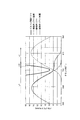
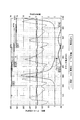
- FIG. 12 is a graph showing the relationship between the conventional crank angle and the exhaust pressure / boost pressure / in-cylinder pressure.
- This figure shows only the first to third cylinders, and the fourth to sixth cylinders are omitted.
- the exhaust pressure of the first to third cylinders oscillates synchronously in a cycle of 240 °.
- This waveform is pulsating.
- the amplitude of the pulsations falls generally in the range of 60 to 250 kPa.
- the boost pressure is stable at about 150 kPa.
- the in-cylinder pressure of the first cylinder reaches a peak when the crank angle slightly exceeds 360 °, and then reaches the next peak when the crankshaft rotates 720 °.
- variable valve timing mechanism is performed as a method of changing the open / close timing of the valve, the mechanism becomes complicated, the load of calculation increases, and the program becomes complicated, It was disadvantageous in terms of cost.
- the present invention is an exhaust that can circulate as much exhaust gas as possible from another cylinder to one cylinder without contact between the piston and the exhaust valve and without electronic control.
- An object of the present invention is to provide a valve lift cam and a four-stroke engine with a supercharger and a valve timing control method.
- the cam for raising and lowering the exhaust valve according to the present invention is an exhaust gas recirculation device which circulates the exhaust gas exhausted from the exhaust port of the other cylinder into the cylinder of the one cylinder through the exhaust port of the one cylinder.
- An exhaust lift is provided to delay the closing timing of the exhaust valve or maintain a high lift amount, and the exhaust main lift and the reflux lift avoid contact with the exhaust valve and the piston while exhausting the other cylinders. It is characterized in that it is raised from the base circle so as to increase the amount of overlap with the valve.
- the exhaust valve lift cam and the exhaust lift valve lift cam are formed on the exhaust valve pressing cam, and the exhaust valve can be raised and lowered so as to avoid contact between the exhaust valve and the piston.
- the circulating lift portion a convex portion smaller than the exhaust main lift portion is formed, a linear outline is formed, or an equal lift or equal velocity lift period is provided.
- the product of the valve lift amount and the width of the crank angle in the conventional normal valve lift line diagram that is, the accumulated opening area over time of the exhaust port An increase is made. This increases the product of the opening area of the exhaust port and time.
- the amount of the recirculated exhaust gas flowing in from the exhaust port after the top dead center is increased by the presence of the reflux lift portion.
- the cylinder through which exhaust gas is circulated is referred to as one cylinder, and the other cylinders are referred to as other cylinders.
- the reflux lift portion has an equal lift portion in which the lift amount of the exhaust valve is constant for a predetermined period.
- the exhaust valve does not descend for a predetermined period, and accordingly, the product of the valve lift amount and the width of the crank angle (a cumulative opening area of the port over time) increases, and the recirculated exhaust gas from other cylinders Can increase the amount of
- the exhaust valve of one cylinder is opened in order to open the exhaust valve of one cylinder while the exhaust pressure of the other cylinder is higher than the charging pressure of the one cylinder.
- the timing of closing is set to 24 ° to 130 ° after compression top dead center, and in order to promote mixing of the supplied air within the one cylinder and the exhaust gas circulated from the other cylinder,
- the opening timing of the intake valve of the cylinder is set to 55 ° to 5 ° before compression top dead center.
- the product of the valve lift amount and the width of the crank angle (port) is more than the line (relationship between the crank angle and the valve lift amount) of the normal curved valve lift amount. It is possible to increase the cumulative aperture area) of That is, it is possible to further increase the amount of recirculated exhaust gas. Note that closing as it is means that the exhaust valve is seated in the state of constant velocity lift.
- the reflux lift portion has a constant velocity lift portion in which the lift speed of the exhaust valve is constant.
- the constant velocity lift portion is provided as described above, the amount of recirculated exhaust gas is increased accordingly.
- the degree of freedom in design is high, and it is possible to design the exhaust valve of one cylinder close to the piston top surface as much as possible. It can be increased significantly.
- cam profile used for each cylinder is usually the same, it is preferable to combine a plurality of cam profiles according to the difference in the amount of reflux as one embodiment of the present invention.
- Increase the exhaust pressure more than the charge pressure (boost pressure) the closing timing of the exhaust valves of the 2nd and 3rd cylinders have a later profile, and the exhaust pressure becomes larger than the charge pressure (boost pressure)
- the closing timing of the exhaust valve of the first cylinder which has a short period, has a profile that closes earlier than the second and third cylinders.
- the supercharged four-stroke engine includes an exhaust gas recirculation system for recirculating the exhaust gas exhausted from the exhaust port of the other cylinder into the cylinder of the one cylinder via the exhaust port of the one cylinder,
- the exhaust valve pressing cam for one cylinder is for increasing the exhaust gas flow rate flowing into the exhaust port of one cylinder from the other exhaust main lift portion for exhausting exhaust gas from the inside of the cylinder and the other cylinder.
- An exhaust valve is formed on the rotation direction down side of the exhaust valve pressing cam to delay the closing timing of the exhaust valve or maintain the lift amount high, and the exhaust valve and the exhaust valve of the other cylinder while avoiding contact with the piston.
- the engine exhaust side is provided with a supercharger into which exhaust gas exhausted from each cylinder flows in, so as to increase the overlap amount with the base circle. It is characterized in.
- the valve timing is appropriately adjusted mechanically.
- exhaust of the third cylinder is performed in the first cylinder using the common portion of the exhaust manifold
- the gas can circulate the exhaust gas of the fourth cylinder to the sixth cylinder, which greatly contributes to NOx reduction.
- the mechanism since it is only necessary to change the shape of the cam when applying the present invention, the mechanism is not complicated, the computational burden on the engine control unit (ECU) is not increased, and the program is complicated. There is no need to In short, the present invention can be applied with minor design changes to conventional mass-produced products.
- the present invention is preferably applied to a large diesel engine. For example, it can be applied to land generators, ships and trucks.
- An exhaust manifold provided on the engine exhaust side is connected to a first exhaust side pipe into which exhaust gas exhausted from each cylinder of multiple cylinders flows, and a central portion of the exhaust side first pipe, and is a turbine of the turbocharger. It is preferable to provide the exhaust side second piping connected to.
- the first cylinder is the exhaust gas of the third cylinder
- the second cylinder is the exhaust gas of the first cylinder
- the third cylinder is the exhaust gas of the second cylinder
- the exhaust gas from the fifth cylinder can be circulated to the fourth cylinder, the exhaust gas from the sixth cylinder to the fifth cylinder, and the exhaust gas from the fourth cylinder to the sixth cylinder.
- the amount of overlap between the exhaust valve and the intake valve is greater than the amount of overlap between the second to fifth cylinders. You should make it smaller.
- the length of flow through the exhaust manifold is for two cylinders between the first and third cylinders and between the fourth and fifth cylinders, and the intake of exhaust gas to the first and sixth cylinders is the other It is difficult to do so compared to the intake of exhaust gas to the cylinder. Therefore, as in the present invention, reducing the amount of overlap between the exhaust valves and the intake valves of the first and sixth cylinders does not significantly affect the NOx reduction effect. If the amount of exhaust gas recirculation increases excessively, black smoke specific to the diesel engine increases. Rather, it is preferable to reduce the amount of overlap between the first cylinder and the sixth cylinder to suppress the generation of black smoke.
- the present invention is applicable not only to a six-cylinder engine but also to an engine consisting of an even-numbered one of six to sixteen cylinders.
- the amount of overlap between the intake valve and the exhaust valve in the first cylinder and the sixth cylinder may not be reduced, but the cylinder itself may be reduced.
- the cylinder reduction operation may be preferentially performed from a cylinder with a low intake amount of the exhaust gas to be circulated.
- This is not limited to six-cylinder engines.
- a diesel fuel-natural gas dual fuel engine that uses natural gas as the main fuel and a small amount of pilot fuel gas oil as the ignition source, it has been confirmed that combustion is reduced because the natural gas premixed fuel is diluted at low load. Therefore, by reducing the number of operating cylinders and increasing the load per cylinder, it is possible to increase the natural gas concentration and reduce the oxygen concentration, to reduce NOx at low load and improve the thermal efficiency.
- valve timing control method of the present invention the same function and effect as those in the case where the engine is driven using the exhaust valve lift cam can be obtained.
- the valve timing is appropriately adjusted mechanically, so for example, the first cylinder, the fifth cylinder, the third cylinder, the sixth cylinder, the second cylinder, the fourth cylinder have an ignition order.
- the first cylinder is the exhaust gas of the third cylinder
- the second cylinder is the exhaust gas of the first cylinder
- the third cylinder is the exhaust gas of the second cylinder
- the exhaust gas of the fifth cylinder can be circulated to the fourth cylinder, the exhaust gas of the sixth cylinder to the fifth cylinder, and the exhaust gas of the fourth cylinder to the sixth cylinder.
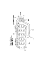
- FIG. 1 shows an outline of a supercharged 4-cycle engine of the present invention.
- the four-stroke engine of this embodiment assumes a diesel engine. Then, on the air supply side of the exhaust system 1 of the engine according to the present embodiment, a comb-teeth-like first air supply side pipe K1 into which the air supply air drawn into each of the six cylinders flows, and the turbocharger 2 And a second supply pipe K2 connected to the central portion of the first supply pipe K1.
- An air supply manifold KM is configured by the air supply side first pipe K1 and the air supply side second pipe K2.
- the exhaust side of the four-stroke engine is connected to a comb-like first exhaust side pipe H1 into which exhaust gas exhausted from each of the six cylinders flows, and a central portion of the exhaust side first pipe H1 for turbo And a single exhaust side second pipe H2 connected to the turbine 22 of the turbocharger 2.
- An exhaust manifold HM is configured by the exhaust side first pipe H1 and the exhaust side second pipe H2.
- Each cylinder is provided with an intake valve 3A and an exhaust valve 3B.
- two intake valves 3A and two exhaust valves 3B are provided for each cylinder.
- the two intake valves 3A and the exhaust valves 3B for each cylinder move up and down in synchronization with each other.
- the pressure change in the exhaust system determines the recirculation direction of the exhaust gas, so the pressure in the turbine 22 of the turbocharger 2 also affects the momentum and direction of the recirculation.
- the first cylinder (denoted # 1 in the figure) to the sixth cylinder (denoted # 6 in the figure) are arranged in order, and the first cylinder is the third cylinder.
- the exhaust gas is the second cylinder, the exhaust gas of the first cylinder, the exhaust gas of the second cylinder is the third cylinder, the exhaust gas of the fifth cylinder is the fourth cylinder, and the exhaust gas of the sixth cylinder is the fifth cylinder.
- the valve timing is such that the exhaust gas of the fourth cylinder is recirculated to the sixth cylinder. This valve timing is made by devising the shape of the cam as described later. This is the biggest feature of the present invention.
- the firing order of the present embodiment is the order of the first cylinder, the fifth cylinder, the third cylinder, the sixth cylinder, the second cylinder, and the fourth cylinder. Therefore, with respect to the first cylinder, the phase difference between the second cylinder is 480 °, the third cylinder is 240 °, the fourth cylinder is 600 °, the fifth cylinder is 120 °, and the sixth cylinder is 360 °. is there. Therefore, the exhaust gas recirculation from the third cylinder to the first cylinder and the exhaust gas recirculation from the fourth cylinder to the sixth cylinder are performed with a phase difference of 360 °.
- the circulation of the exhaust gas from the first cylinder to the second cylinder and the circulation of the exhaust gas from the sixth cylinder to the fifth cylinder are performed with a phase difference of 360 °. Furthermore, the circulation of the exhaust gas from the second cylinder to the third cylinder and the circulation of the exhaust gas from the fifth cylinder to the fourth cylinder are performed with a phase difference of 360 °. In this six-cylinder engine, one explosion is performed in any of the cylinders each time the crankshaft rotates 120 degrees.
- the ignition order is, for example, the order of the first cylinder, the fourth cylinder, the second cylinder, the sixth cylinder, the third cylinder, and the fifth cylinder
- the crank angle of 120.degree When there is a phase difference, the second cylinder to the first cylinder, the third cylinder to the second cylinder, the first cylinder to the third cylinder, the fourth cylinder to the fifth cylinder, the sixth cylinder to the fourth cylinder , Circulation is performed from the fifth cylinder to the sixth cylinder.
- the first to third cylinders are the first cylinder when the ignition order is continuously arranged without dividing the circulation.
- the order may be such that the cylinders are arranged in order, and the fourth to sixth cylinders are arbitrarily inserted one by one between the first to third cylinders.
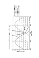
- FIG. 2 shows the relationship between the crank angle and the valve lift in the first embodiment of the supercharged 4-cycle engine of the present invention.
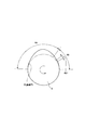
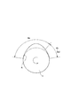
- FIG. 3 shows the shape of the cam used in the first embodiment.
- the graph shown by the solid line in the figure the graph of the conventional valve lift amount shown by the one-dot chain line in the figure is divided into two areas L1 and L2, and these areas are connected by the area L3 where the constant lift amount continues. It is At this time, in order to make the graph smooth, after the exhaust valve descent starts, the reduction rate of the valve lift amount is slightly faster than before, and it reverses around top dead center (crank angle 720 °) to area L3. move on.
- the thick solid line indicates the position of the top face of the piston, and it is designed to avoid the valve and the valve conflict when the valve head enters the area inside the thick solid line. .
- the dashed-dotted line is a graph of the valve lift amount of the conventional exhaust valve, which has the same shape as the graph of the intake valve shown by the broken line in the drawing. That is, conventionally, the same type of cam is used for the intake valve and the exhaust valve.
- the lift amount change of the exhaust valve of the present embodiment is as shown by the solid line in the figure as described above.
- the valve lift amount of the solid line is larger than the one-dot chain line (conventional product) from the front of the crank angle of 720 °.
- the valve lift amount becomes constant at about 740 ° to 755 °.
- This portion corresponds to the equal lift portion 4b1 shown in FIG.
- This portion corresponds to an arc portion which is a part of a concentric circle slightly larger than the base circle R.
- the valve lift amount shown by a solid line monotonously decreases monotonously.
- the top dead center (TDC) is the crank angle 720 ° at which the height of the piston top is the highest, and the valve lift amount is larger than that of the conventional product from near the top dead center. Gas circulates from the exhaust port into the cylinder.
- the return lift portion 4b formed on the rotational direction down side of the exhaust valve pressing cam 4 has the equal lift portion 4b1 in which the lift amount of the exhaust valve 3B is constant for a predetermined period. Since the exhaust valve 3B does not descend, the product of the valve lift amount and the width of the crank angle increases, that is, the cumulative opening area of the exhaust port increases with time, and the amount of recirculated exhaust gas from other cylinders increases. Do. Note that the predetermined period refers to a partial period from when the exhaust valve 3B starts to descend until it is seated. When the valve lift amount is constant for a predetermined period, it becomes parallel to the horizontal axis. That is, constant means that the valve lift does not change. If it becomes a straight line having an inclination with respect to this horizontal axis, it becomes not an equal lift part but an equal velocity lift part.
- the exhaust valve pressing cam 4 has the exhaust main lift portion 4a raised from the base circle R so as to increase the overlap amount with the exhaust valves of the other cylinders while avoiding contact between the exhaust valve and the piston. have.
- the exhaust main lift portion 4a is formed to exhaust the exhaust gas from the inside of the cylinder.
- a reflux lift portion 4b is formed to increase the flow rate of the exhaust gas to the air supply side. Due to the presence of the lift portion 4b for reflux, it is possible to delay the closing timing of the exhaust valve 3B and maintain the lift amount as high as possible.
- the equal lift portion 4b1 is included in the return lift portion 4b.
- the basic configuration is that the contour curve of the cam is determined by superposing the arc-shaped swelled portion of the exhaust main lift portion 4a and the arc-shaped swelled portion of the return lift portion 4b, and as a result, the equal lift portion 4b1 and a constant velocity lift unit described later are formed.
- a hump-shaped cam outer contour may be formed.
- the top dead center of the piston may be between the two bumps while avoiding contact between the piston and the valve.
- the lift portion 4 b for reflux is formed only on the downstream side of the main lift portion 4 a in the cam rotation direction, but the cam shape may be symmetrical. Even if the closing timing of the exhaust valve 3B of the first cylinder is delayed to widen the opening area of the exhaust port of the first cylinder at the time of recirculation, the timing to start the opening of the exhaust valve 3B of the third cylinder is advanced to exhaust the third cylinder. Even if the opening area of the port is expanded, it contributes to the recirculation of the exhaust gas from the third cylinder to the first cylinder.
- the reflux lift portion 4b and the exhaust main lift portion 4a are formed with respect to a base circle R centered on the rotation center, and a plurality of raised portions are superimposed on each other. Therefore, the division of the strict areas L1 to L3 is not made. Therefore, the positions of the areas L1 to L3 in the graph of FIG. 2 also include some errors.
- the present embodiment is characterized in that the equal lift portion (area L3) is provided between the area L1 and the area L2 of the conventional product, whereby the product of the crank angle and the valve lift amount is increased.
- the circulation flow rate of the exhaust gas from the cylinder of the above may be increased.
- the elevating mechanism of the valve may be performed via a tappet, a push rod, a rocker arm, or even if a cup-shaped valve lifter is sandwiched between the cam and the valve and the valve lifter is struck directly at the bulging portion of the cam.
- this mechanism is not particularly limited.
- the cam is integrally formed on the camshaft, and the angle around the camshaft is changed for each cylinder in accordance with the phase shift between the cylinders.
- the valve timing is appropriately adjusted. Therefore, the exhaust gas of the third cylinder is transmitted to the first cylinder, the exhaust gas of the first cylinder to the second cylinder, The exhaust gas of the second cylinder is circulated to the third cylinder, the exhaust gas of the fifth cylinder to the fourth cylinder, the exhaust gas of the sixth cylinder to the fifth cylinder, and the exhaust gas of the fourth cylinder to the sixth cylinder. it can.
- the mechanism since it is only necessary to change the shape of the cam upon application of the present embodiment, the mechanism does not become complicated, the computational load on the engine control unit (ECU) does not increase, and the program There is no complication. That is, this embodiment can be applied to a conventional mass product with minor design changes.
- the width of the crank angle in the areas L1 to L3 is adjusted, and the overlap amount between the exhaust valve 3B and the intake valve 3A in the first cylinder and the sixth cylinder It is better to make it smaller than the overlap amount of 5 cylinders.
- the length flowing through the exhaust manifold HM is for two cylinders between the first and third cylinders and between the fourth and fifth cylinders, and the intake of exhaust gas to the first and sixth cylinders is It is difficult to do compared to the intake of exhaust gas to the Therefore, as in the present embodiment, even if the overlap amount between the exhaust valve 3B and the intake valve 3A of the first cylinder and the sixth cylinder is reduced, the NOx reduction effect is not significantly affected.
- the present invention is applicable not only to a six-cylinder engine but also to an engine consisting of an even number of six or more cylinders.
- the cylinder itself may be reduced.
- the cylinder reduction operation may be preferentially performed from a cylinder with a small intake amount of the reflux exhaust gas.
- a diesel fuel-natural gas dual fuel engine that uses natural gas as the main fuel and a small amount of pilot fuel gas oil as the ignition source, it has been confirmed that combustion is reduced because the natural gas premixed fuel is diluted at low load. Therefore, by reducing the number of operating cylinders and increasing the load per cylinder, it is possible to increase the natural gas concentration and reduce the oxygen concentration, to reduce NOx at low load and improve the thermal efficiency.
- the present invention may change the exhaust manifold HM as follows. That is, as shown in FIG. 4, an exhaust manifold HH having a common exhaust portion to which exhaust gas exhausted from each cylinder flows in and is connected to the turbine 22 of the turbocharger 2 may be provided. In this configuration, the exhaust gas of the third cylinder is circulated to the first cylinder, and the exhaust gas of the fourth cylinder is circulated to the sixth cylinder. Even with this configuration, the same effect as that of the above-described embodiment can be obtained.
- FIG. 5 shows a valve timing diagram applied to a second embodiment of the supercharged four-stroke engine of the present invention.
- the same members as those in the first embodiment are denoted by the same reference numerals, and the description thereof will be omitted.
- the exhaust valve pressing cam 4 for one cylinder prevents the contact between the exhaust valve 3B and the piston while the overlap amount of the exhaust valve 3B of the other cylinder
- the exhaust main lift 4a for exhausting the exhaust gas from the inside of the cylinder raised from the base circle R so as to increase the flow rate of the exhaust gas to the exhaust ports of other cylinders And a lift unit 4b.
- one cylinder is opened in order to open the intake valve 3A and the exhaust valve 3B of one cylinder while the exhaust pressure of the other cylinder is higher than the air supply pressure of the one cylinder.
- the closing timing of the exhaust valve 3B is set to 24.degree. To 130.degree. After compression top dead center.
- the opening timing of the intake valve 3A of one cylinder is set to 55 ° to 5 ° before the compression top dead center. ing.
- the exhaust main lift 4a for exhausting the exhaust gas from the inside of the cylinder to the exhaust valve pressing cam 4 for one cylinder, and the flow rate to the air supply side of the exhaust gas are increased.
- a lift portion 4b for reflux The lift portions 4a and 4b are raised from the base circle R so as to increase the amount of overlap of the exhaust valves 3B of the other cylinders while avoiding contact between the exhaust valve 3B and the piston.
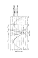
- FIG. 6 shows the relationship between the crank angle and the valve lift amount in the third embodiment of the supercharged 4-cycle engine of the present invention.
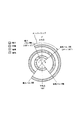
- FIG. 7 shows the shape of a cam used in the third embodiment.
- the same members as those in the first embodiment are denoted by the same reference numerals, and the description thereof will be omitted.
- the graph shown by the solid line in FIG. 6 is a graph in which the conventional valve lift graph shown by the one-dot chain line is divided into area L1 and area L2 and the exhaust valve lifts at the same speed in area L2. is there.
- the return lift portion 4b of the exhaust valve pressing cam 4 corresponds to a constant velocity lift portion 4b2 in which the exhaust valve 3B lifts at a constant velocity.
- the relationship between the crank angle and the valve lift amount is graphed using the exhaust valve pressing cam 4 as shown in FIG. That is, in the figure, the solid-line chevron portion corresponds to the exhaust main lift portion 4a, and the straight portion from the top dead center (crank angle of about 710 °) following the exhaust main lift portion 4a is the constant velocity lift portion 4b2. Equivalent to.
- the inclination of the constant velocity lift portion 4b2 is made as gentle as possible, and it is possible to increase the product of the valve lift amount and the width of the crank angle, that is, the accumulated opening area of the port with time. That is, it is possible to further increase the amount of reflux gas over time.
- the straight line of the constant velocity lift portion 4b2 directly collides with the horizontal axis of the valve lift 0. Leads to the axis of the crank angle. That is, at the end of the constant velocity lift portion 4b2, the exhaust valve is seated and closed just right. Due to the presence of the constant velocity lift portion 4b2, the closing timing of the exhaust valve 3B can be delayed and the lift amount can be maintained high, as compared with the conventional product shown by the one-dot chain line in FIG.
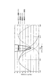
- FIG. 8 shows the relationship between the crank angle and the valve lift amount in the fourth embodiment of the supercharged 4-cycle engine of the present invention.
- FIG. 9 shows the shape of a cam used in the fourth embodiment. The same members as those in the first embodiment are denoted by the same reference numerals, and the description thereof will be omitted.
- the graph shown by the solid line in FIG. 8 the graph of the conventional valve lift amount shown by the one-dot chain line in the figure is divided into two areas L1 and L2, and lifts between area L1 and area L2 at the same speed. It is drawn to connect in the area L3 where the amount decreases.
- the reflux lift portion 4b has a constant velocity lift portion 4b2 in which the lift speed of the exhaust valve 3B is constant.
- the third embodiment differs from the third embodiment in that the valve is closed at the end of the constant velocity lift portion 4b2, but in the present embodiment, as shown in FIG. 8, the valve is smooth after the constant velocity lift portion 4b2. This is the point at which the valve lift decreases in the curve.
- the closing timing of the valve lift amount is delayed and the lift amount is maintained high.
- the amount of reflux gas increases accordingly.
- a raised portion from the base circle R can be formed in three stages, the degree of freedom in design is high, and the exhaust gas amount of one cylinder is made close to the piston top surface as much as possible. It is possible to increase In the embodiment described above, an example in which one constant velocity lift portion 4b2 is formed has been described, but a plurality may be formed and the exhaust valve 3B may be lowered stepwise.
- Fifth Embodiment Profiles are selected for each of the cylinders according to the exhaust pulsations that are different for each of the cylinders. That is, the exhaust main lift portion and the return lift portion are provided, and the shape of the exhaust valve lift cam is provided for each cylinder. As a result, it is possible to relatively increase the amount of exhaust pulsation recirculation exhaust gas that matches each of the cylinders.
- exhaust valve lifting cam and supercharger 4-cycle engine and valve timing control method of the present invention as much exhaust gas as possible can be circulated to other cylinders without contact between the piston and the exhaust valve. It can be applied to land generators, marine engines, etc.
Abstract
Description
しかし、陸用発電機や船舶などに使用される大型過給機付き4サイクルディーゼルエンジンでは、排気マニホルドの排気ガスの圧力より給気マニホルドの給気ガスの圧力の方が高く、排気ガスを給気側に循環させる一般的な排気ガス再循環(EGR)を大量に行うことが困難であった。 An exhaust gas recirculation system (EGR system) that reduces the concentration of generated NOx by reducing the oxygen concentration inside the cylinder is widely known, but this generally applies to the exhaust manifold of the exhaust manifold. To reduce the oxygen concentration inside the cylinder, and the EGR device is established by the relationship between the exhaust side and the air supply side.
However, in a large supercharged 4-cycle diesel engine used for land generators, ships, etc., the pressure of the charge gas in the charge manifold is higher than the pressure of the exhaust gas in the exhaust manifold, and the exhaust gas is supplied. It has been difficult to perform a large amount of general exhaust gas recirculation (EGR) circulating to the air side.
なお、従来、4サイクルディーゼルエンジンでは、非特許文献1に示すようなタイミングでのバルブの開閉が一般的に行われていた。このバルブ開閉タイミングについては、特許文献1では具体的には開示されていなかった。 Therefore, exhaust gas recirculation technology has been developed in which the exhaust gas exhausted from the exhaust port of one cylinder is directly fed to the exhaust port of the other cylinder (see, for example, Patent Document 1). In the four-stroke diesel engine disclosed in
In the conventional four-stroke diesel engine, opening and closing of the valve at the timing as shown in Non-Patent
そこで、この干渉を避けるために、対策の1つとして、シリンダヘッドと、上死点に位置するピストンとで形成されるいわゆる燃焼室を大きくする方法が挙げられる。しかし、燃焼室を大きくすると熱効率が低下する。この熱効率の低下を避けるためには、例えば、ピストン頂面にバルブリセスを形成しピストンとバルブとの干渉を防止するとよい(例えば、特許文献2参照)。しかし、バルブリセスが大きいと主燃焼室の容積が減少し、排気ガス中の炭化水素及び黒煙の濃度が上昇する(例えば、特許文献2参照)。そのため、バルブリセスを大きくする設計変更を行わないで、ピストンとバルブとの干渉を避け、且つ、一の気筒の排気ポートから他の気筒の排気ポートへ排気ガスを環流させることが好ましい。
なお、6気筒の4サイクルエンジンの着火順序としては、第1気筒、第4気筒、第2気筒、第6気筒、第3気筒、第5気筒の順、又は第1気筒、第3気筒、第5気筒、第6気筒、第4気筒、第2気筒の順で行われる旨が開示されている(非特許文献2参照)。 However, the period during which the recirculation from the third cylinder to the first cylinder is performed is about 60 ° after passing the top dead center (TDC) of the first cylinder, but the exhaust valve of the first cylinder is passed after the top dead center When designed to sit on the valve seat at 60 ° and close the exhaust port, the exhaust valve of the first cylinder is open at top dead center and the piston is at its highest position at top dead center. And may interfere with each other (see FIG. 11).
In order to avoid this interference, one of the measures is to enlarge the so-called combustion chamber formed by the cylinder head and the piston located at the top dead center. However, increasing the size of the combustion chamber reduces the thermal efficiency. In order to avoid this reduction in thermal efficiency, for example, a valve recess may be formed on the top of the piston to prevent interference between the piston and the valve (see, for example, Patent Document 2). However, when the valve recess is large, the volume of the main combustion chamber decreases, and the concentration of hydrocarbons and black smoke in the exhaust gas increases (see, for example, Patent Document 2). Therefore, it is preferable to avoid the interference between the piston and the valve and divert the exhaust gas from the exhaust port of one cylinder to the exhaust port of the other cylinder without making a design change for enlarging the valve recess.
In addition, as the firing order of the six-cylinder four-stroke engine, the first cylinder, the fourth cylinder, the second cylinder, the sixth cylinder, the third cylinder, the fifth cylinder, or the first cylinder, the third cylinder, the fourth cylinder. It is disclosed that the five cylinders, the sixth cylinder, the fourth cylinder, and the second cylinder are performed in this order (see Non-Patent Document 2).
本発明の排気バルブ昇降用カムは、他の気筒の排気ポートから排気された排気ガスを一の気筒の排気ポートを介して該一の気筒のシリンダ内に環流させる排気環流装置であって、排気ガスをシリンダ内から排気するための排気主リフト部と、他の気筒から一の気筒の排気ポートへ流入する排気ガス環流量を増加させるために前記排気バルブ押圧カムの回転方向ダウン側に形成され排気バルブの閉時期を遅らせ又はリフト量を高く維持する環流用リフト部とが設けられ、前記排気主リフト部と環流用リフト部は排気バルブとピストンとの接触を回避しつつ他の気筒の排気バルブとのオーバーラップ量を増加させるように、基礎円から盛り上げられて形成されていることを特徴とする。 The present invention has been made as means for solving such problems.
The cam for raising and lowering the exhaust valve according to the present invention is an exhaust gas recirculation device which circulates the exhaust gas exhausted from the exhaust port of the other cylinder into the cylinder of the one cylinder through the exhaust port of the one cylinder. The exhaust main lift for exhausting gas from the inside of the cylinder, and the rotational direction down side of the exhaust valve pressing cam for increasing the flow rate of the exhaust gas ring flowing from the other cylinder to the exhaust port of one cylinder An exhaust lift is provided to delay the closing timing of the exhaust valve or maintain a high lift amount, and the exhaust main lift and the reflux lift avoid contact with the exhaust valve and the piston while exhausting the other cylinders. It is characterized in that it is raised from the base circle so as to increase the amount of overlap with the valve.
なお、本発明では、一の気筒に着目した場合に、排気ガスが環流される気筒を一の気筒と称し、この気筒以外を他の気筒と称している。 In this invention, the exhaust valve lift cam and the exhaust lift valve lift cam are formed on the exhaust valve pressing cam, and the exhaust valve can be raised and lowered so as to avoid contact between the exhaust valve and the piston. As the circulating lift portion, a convex portion smaller than the exhaust main lift portion is formed, a linear outline is formed, or an equal lift or equal velocity lift period is provided. Thus, in the present invention, the product of the valve lift amount and the width of the crank angle in the conventional normal valve lift line diagram (relationship diagram between crank angle and valve lift amount), that is, the accumulated opening area over time of the exhaust port An increase is made. This increases the product of the opening area of the exhaust port and time. Then, the amount of the recirculated exhaust gas flowing in from the exhaust port after the top dead center is increased by the presence of the reflux lift portion.
In the present invention, when focusing on one cylinder, the cylinder through which exhaust gas is circulated is referred to as one cylinder, and the other cylinders are referred to as other cylinders.
このようにすると、排気バルブが所定期間下降しなくなるので、その分、バルブリフト量とクランク角の幅との積(ポートの経時的累積開口面積)が増加し、他の気筒からの環流排気ガスの量を増加させることができる。 As one aspect of the present invention, it is preferable that the reflux lift portion has an equal lift portion in which the lift amount of the exhaust valve is constant for a predetermined period.
In this case, the exhaust valve does not descend for a predetermined period, and accordingly, the product of the valve lift amount and the width of the crank angle (a cumulative opening area of the port over time) increases, and the recirculated exhaust gas from other cylinders Can increase the amount of
そして、酸素濃度の濃淡があると、酸素濃度の低いところで黒鉛の発生が多く、酸素濃度の高いところでNOxの発生が多いため、好ましくない。酸素濃度の濃淡を防止するためにはシリンダ内のスワール比を大きくする方法があるが、スワール比を大きくすると一般的にはエアの吸入量の低下を伴うので、排気を新気と衝突させて攪拌させる方がエアの吸入量の低下もなく好適である。 In this setting, since the overlap amount of the open period of the exhaust valve and the intake valve of one cylinder is taken as long as possible, the air from the intake port and the exhaust gas from the exhaust port are sufficient. Mix. With this mixing, concentration of oxygen concentration does not easily occur in the combustion process, and the mixture is homogenized, so that the generation of soot after combustion and the generation of NOx are reduced. In particular, if the exhaust gas is circulated at the timing of performing the reflux of the present embodiment, there is a time margin for approximately one revolution of the engine until the actual combustion, so diffusion of gas in the mixture and homogenization of the mixture are realized. Will be done well. In addition, although what is made into the cam shape which seats twice in one cycle of four exhaust valves is known, in this case, the mixing time which homogenizes air-fuel mixture can not fully be ensured.
And, if there is concentration of oxygen concentration, it is not preferable because a large amount of graphite is generated at a low oxygen concentration and a large amount of NOx is generated at a high oxygen concentration. In order to prevent concentration of oxygen concentration, there is a method of increasing the swirl ratio in the cylinder. However, increasing the swirl ratio generally reduces the intake amount of air, so the exhaust gas collides with fresh air. Stirring is preferable without a reduction in the amount of intake of air.
このように、なるべく緩やかに等速リフトさせることにより、通常の湾曲したバルブリフト量のライン(クランク角とバルブリフト量との関係図)よりもバルブリフト量とクランク角の幅との積(ポートの経時的累積開口面積)を多くすることが可能である。すなわち、環流排気ガス量をより多くすることが可能である。なお、そのままクローズするとは、等速リフトの状態で排気バルブが着座することをいう。 Alternatively, as one aspect of the present invention, in the lift unit for reflux, it is preferable that the exhaust valve lifts at a constant velocity, and the exhaust valve closes in the constant velocity state.
In this way, by making the constant velocity lift as gentle as possible, the product of the valve lift amount and the width of the crank angle (port) is more than the line (relationship between the crank angle and the valve lift amount) of the normal curved valve lift amount. It is possible to increase the cumulative aperture area) of That is, it is possible to further increase the amount of recirculated exhaust gas. Note that closing as it is means that the exhaust valve is seated in the state of constant velocity lift.
このように等速リフト部を設けると、その分、環流排気ガス量が増加する。また、基礎円から盛り上がった部分を3段階に分ける形状であるので、設計の自由度が高く、なるべくピストン頂面に一の気筒の排気バルブを近づけるように設計することができ、環流ガス量を大幅に増加させることが可能である。 Alternatively, as one aspect of the present invention, it is preferable that the reflux lift portion has a constant velocity lift portion in which the lift speed of the exhaust valve is constant.
When the constant velocity lift portion is provided as described above, the amount of recirculated exhaust gas is increased accordingly. In addition, since it is a shape that divides the raised portion from the base circle into three steps, the degree of freedom in design is high, and it is possible to design the exhaust valve of one cylinder close to the piston top surface as much as possible. It can be increased significantly.
排気圧力が給気圧力(ブースト圧力)より大きくなる期間が長くなる、第2、第3気筒の排気バルブの閉じタイミングはより遅くなるプロフィールとし、排気圧力が給気圧力(ブースト圧力)より大きくなる期間が短い、第1気筒の排気バルブの閉じタイミングは第2、第3気筒に比べ早く閉じるプロフィールとする。還流量をできるだけ多くするためには排気バルブの開いている期間を長くしたいが、全気筒共通で長くすると、第1気筒では排気圧力が給気圧力に負け、給気が吹き抜けてしまい効果を減ずる。
このように排気脈動にそれぞれ合わせたプロフィールを選定すると、その分、環流排気ガス量を相対的に増加させることが可能である。 In addition, although the cam profile used for each cylinder is usually the same, it is preferable to combine a plurality of cam profiles according to the difference in the amount of reflux as one embodiment of the present invention.
Increase the exhaust pressure more than the charge pressure (boost pressure), the closing timing of the exhaust valves of the 2nd and 3rd cylinders have a later profile, and the exhaust pressure becomes larger than the charge pressure (boost pressure) The closing timing of the exhaust valve of the first cylinder, which has a short period, has a profile that closes earlier than the second and third cylinders. In order to increase the amount of recirculation as much as possible, it is desirable to lengthen the open period of the exhaust valve, but if the length is common to all cylinders, the exhaust pressure loses the charge pressure in the first cylinder and the charge is blown away, reducing the effect .
Thus, if the profiles respectively matched to the exhaust pulsation are selected, it is possible to relatively increase the amount of recirculated exhaust gas.
本発明は大型のディーゼルエンジンに好適に適用される。例えば、陸用発電機、船舶及びトラックに適用可能である。 In the four-stroke engine with supercharger having the above-described configuration, the valve timing is appropriately adjusted mechanically. For example, in the case of six cylinders, exhaust of the third cylinder is performed in the first cylinder using the common portion of the exhaust manifold The gas can circulate the exhaust gas of the fourth cylinder to the sixth cylinder, which greatly contributes to NOx reduction. In addition, since it is only necessary to change the shape of the cam when applying the present invention, the mechanism is not complicated, the computational burden on the engine control unit (ECU) is not increased, and the program is complicated. There is no need to In short, the present invention can be applied with minor design changes to conventional mass-produced products.
The present invention is preferably applied to a large diesel engine. For example, it can be applied to land generators, ships and trucks.
このような構成にすると、例えば、6気筒の場合、第1気筒に第3気筒の排気ガスを、第2気筒に第1気筒の排気ガスを、第3気筒に第2気筒の排気ガスを、第4気筒に第5気筒の排気ガスを、第5気筒に第6気筒の排気ガスを、第6気筒に第4気筒の排気ガスを環流させることができる。 An exhaust manifold provided on the engine exhaust side is connected to a first exhaust side pipe into which exhaust gas exhausted from each cylinder of multiple cylinders flows, and a central portion of the exhaust side first pipe, and is a turbine of the turbocharger. It is preferable to provide the exhaust side second piping connected to.
With such a configuration, for example, in the case of six cylinders, the first cylinder is the exhaust gas of the third cylinder, the second cylinder is the exhaust gas of the first cylinder, and the third cylinder is the exhaust gas of the second cylinder, The exhaust gas from the fifth cylinder can be circulated to the fourth cylinder, the exhaust gas from the sixth cylinder to the fifth cylinder, and the exhaust gas from the fourth cylinder to the sixth cylinder.
排気マニホルドを流れる長さが、第1気筒と第3気筒、及び第4気筒と第5気筒との間では、2気筒分あり、第1気筒と第6気筒への排気ガスの吸入が他の気筒への排気ガスの吸入に比べて行い難い。そのため、本発明のように、第1気筒及び第6気筒の排気バルブと吸気バルブのオーバーラップ量を減らしても、NOx低減効果にあまり影響しない。排気ガスの還流量が過剰に増加すると、ディーゼルエンジン特有の黒煙が増加するため、むしろ、第1気筒と第6気筒とのオーバーラップ量を減らして黒煙の発生を抑える方が好ましい。 In the above-mentioned exhaust-circulable supercharged 4-cycle engine, which consists of six cylinders, in the first and sixth cylinders, the amount of overlap between the exhaust valve and the intake valve is greater than the amount of overlap between the second to fifth cylinders. You should make it smaller.
The length of flow through the exhaust manifold is for two cylinders between the first and third cylinders and between the fourth and fifth cylinders, and the intake of exhaust gas to the first and sixth cylinders is the other It is difficult to do so compared to the intake of exhaust gas to the cylinder. Therefore, as in the present invention, reducing the amount of overlap between the exhaust valves and the intake valves of the first and sixth cylinders does not significantly affect the NOx reduction effect. If the amount of exhaust gas recirculation increases excessively, black smoke specific to the diesel engine increases. Rather, it is preferable to reduce the amount of overlap between the first cylinder and the sixth cylinder to suppress the generation of black smoke.
また、6気筒エンジンにおいて、第1気筒と第6気筒での吸気バルブと排気バルブとのオーバーラップ量を小さくするのでなく、気筒自体を減筒運転してもよい。言い換えれば、環流される排気ガスの吸入量の低い気筒から優先的に減筒運転するようにしてもよい。これは、6気筒エンジンに限定されない。
天然ガスを主燃料として少量パイロットした軽油を着火源とする軽油-天然ガスデュアルフューエルエンジンでは、天然ガスの予混合気が低負荷時に希薄化するため燃焼が低下することが確認されている。そこで、運転する気筒を減らし、1気筒当たりの負荷を増大させることで、天然ガス濃度を高めて酸素濃度を減らし、低負荷時のNOxの低減及び熱効率の向上などを図ることができる。 Of course, the present invention is applicable not only to a six-cylinder engine but also to an engine consisting of an even-numbered one of six to sixteen cylinders.
Further, in the six-cylinder engine, the amount of overlap between the intake valve and the exhaust valve in the first cylinder and the sixth cylinder may not be reduced, but the cylinder itself may be reduced. In other words, the cylinder reduction operation may be preferentially performed from a cylinder with a low intake amount of the exhaust gas to be circulated. This is not limited to six-cylinder engines.
In a diesel fuel-natural gas dual fuel engine that uses natural gas as the main fuel and a small amount of pilot fuel gas oil as the ignition source, it has been confirmed that combustion is reduced because the natural gas premixed fuel is diluted at low load. Therefore, by reducing the number of operating cylinders and increasing the load per cylinder, it is possible to increase the natural gas concentration and reduce the oxygen concentration, to reduce NOx at low load and improve the thermal efficiency.
以下、本発明を図に示した実施形態を用いて詳細に説明する。ただし、この実施形態に記載されている構成部品の寸法、材質、形状、その相対位置などは特に記載がない限り、この発明の範囲をそれのみに限定する趣旨ではない。 Hereinafter, the present invention will be described in detail using embodiments shown in the drawings. However, the dimensions, materials, shapes, relative positions, etc. of the component parts described in this embodiment are not intended to limit the scope of the present invention to only the specific description unless specifically described otherwise, and merely illustrative examples It is only
Hereinafter, the present invention will be described in detail using embodiments shown in the drawings. However, the dimensions, materials, shapes, relative positions, and the like of the components described in this embodiment are not intended to limit the scope of the present invention thereto unless otherwise specified.
図1は、本発明の過給機付き4サイクルエンジンの概要を示している。本実施形態の4サイクルエンジンは、ディーゼルエンジンを想定している。そして、本実施形態のエンジンの排気装置1の給気側は、6気筒の各気筒に吸入される給気エアが流入する櫛歯状の給気側第1配管K1と、ターボ過給機2のコンプレッサ21と給気側第1配管K1の中央部とに接続された1本の給気側第2配管K2と、を備えている。給気側第1配管K1と給気側第2配管K2とで給気マニホルドKMが構成されている。
また、4サイクルエンジンの排気側は、6気筒の各気筒から排気される排気ガスが流入する櫛歯状の排気側第1配管H1と、該排気側第1配管H1の中央部に接続されターボ過給機2のタービン22に接続される1本の排気側第2配管H2と、を備えている。排気側第1配管H1と排気側第2配管H2とで排気マニホルドHMが構成されている。
また、各気筒には、吸気バルブ3Aと排気バルブ3Bが設けられている。例えば、1気筒毎に2本ずつの吸気バルブ3Aと排気バルブ3Bが設けられる。この場合、気筒毎の2本の吸気バルブ3Aと排気バルブ3Bとは、それぞれ同期して昇降する。
なお、本実施形態では、排気装置内の圧力変化が排気ガスの環流方向を決定するため、ターボ過給機2のタービン22内の圧力も環流の勢いや方向に影響を与える。 First Embodiment
FIG. 1 shows an outline of a supercharged 4-cycle engine of the present invention. The four-stroke engine of this embodiment assumes a diesel engine. Then, on the air supply side of the
Further, the exhaust side of the four-stroke engine is connected to a comb-like first exhaust side pipe H1 into which exhaust gas exhausted from each of the six cylinders flows, and a central portion of the exhaust side first pipe H1 for turbo And a single exhaust side second pipe H2 connected to the
Each cylinder is provided with an
In the present embodiment, the pressure change in the exhaust system determines the recirculation direction of the exhaust gas, so the pressure in the
本実施形態の着火順序は第1気筒、第5気筒、第3気筒、第6気筒、第2気筒、第4気筒の順である。そのため、第1気筒に対して、第2気筒は480°、第3気筒は240°、第4気筒は600°、第5気筒は120°、第6気筒は360°のクランク角の位相差がある。このため、第3気筒から第1気筒への排気ガスの環流と、第4気筒から第6気筒への排気ガス環流は、360°の位相差を持って行われる。また、第1気筒から第2気筒への排気ガスの環流と、第6気筒から第5気筒への排気ガスの環流は、360°の位相差を持って行われる。さらに、第2気筒から第3気筒への排気ガスの環流と、第5気筒から第4気筒への排気ガスの環流は、360°の位相差を持って行われる。この6気筒エンジンでは、クランクシャフトが120°回転する毎に、いずれかのシリンダ内で1回の爆発が行われる。 In the figure, from the one side to the other side, the first cylinder (denoted # 1 in the figure) to the sixth cylinder (denoted # 6 in the figure) are arranged in order, and the first cylinder is the third cylinder. The exhaust gas is the second cylinder, the exhaust gas of the first cylinder, the exhaust gas of the second cylinder is the third cylinder, the exhaust gas of the fifth cylinder is the fourth cylinder, and the exhaust gas of the sixth cylinder is the fifth cylinder. However, the valve timing is such that the exhaust gas of the fourth cylinder is recirculated to the sixth cylinder. This valve timing is made by devising the shape of the cam as described later. This is the biggest feature of the present invention.
The firing order of the present embodiment is the order of the first cylinder, the fifth cylinder, the third cylinder, the sixth cylinder, the second cylinder, and the fourth cylinder. Therefore, with respect to the first cylinder, the phase difference between the second cylinder is 480 °, the third cylinder is 240 °, the fourth cylinder is 600 °, the fifth cylinder is 120 °, and the sixth cylinder is 360 °. is there. Therefore, the exhaust gas recirculation from the third cylinder to the first cylinder and the exhaust gas recirculation from the fourth cylinder to the sixth cylinder are performed with a phase difference of 360 °. Further, the circulation of the exhaust gas from the first cylinder to the second cylinder and the circulation of the exhaust gas from the sixth cylinder to the fifth cylinder are performed with a phase difference of 360 °. Furthermore, the circulation of the exhaust gas from the second cylinder to the third cylinder and the circulation of the exhaust gas from the fifth cylinder to the fourth cylinder are performed with a phase difference of 360 °. In this six-cylinder engine, one explosion is performed in any of the cylinders each time the crankshaft rotates 120 degrees.
図中、実線で示すグラフは、図中、1点鎖線で示す従来のバルブリフト量のグラフをエリアL1とエリアL2とに2分割し、このエリア間を一定リフト量が継続するエリアL3で接続したものである。この際、グラフをスムーズにするために、排気バルブ下降開始後は、従来よりもバルブリフト量の減少速度が僅かに速く、上死点(クランク角720°)付近で、逆転し、エリアL3に進む。
図中、太実線は、ピストン頂面の位置を示しており、太実線の内側のエリアにバルブの傘部が入ると、ピストンとバルブとが抵触するため、これを避けるように設計されている。 FIG. 2 shows the relationship between the crank angle and the valve lift in the first embodiment of the supercharged 4-cycle engine of the present invention. FIG. 3 shows the shape of the cam used in the first embodiment.
In the graph shown by the solid line in the figure, the graph of the conventional valve lift amount shown by the one-dot chain line in the figure is divided into two areas L1 and L2, and these areas are connected by the area L3 where the constant lift amount continues. It is At this time, in order to make the graph smooth, after the exhaust valve descent starts, the reduction rate of the valve lift amount is slightly faster than before, and it reverses around top dead center (crank
In the figure, the thick solid line indicates the position of the top face of the piston, and it is designed to avoid the valve and the valve conflict when the valve head enters the area inside the thick solid line. .
本実施形態の排気バルブのリフト量変化は、上述したように図中、実線に示すようになる。同図では、クランク角720°の手前から、1点鎖線(従来品)よりも実線(本願発明品)のバルブリフト量が大きくなっている。そして、本願発明品では、740°~755°程度でバルブリフト量が一定となる。この部分は、図3で示す等リフト部4b1に相当する。この部分は、基礎円Rより少し大きめの同心円の一部である円弧部に相当する。
等リフト部4b1の後、実線で示すバルブリフト量は、なだらかに単調減少する。この実線のグラフによれば、ピストン頂面の高さが最も高くなるクランク角720°が上死点(TDC)であり、この上死点付近からバルブリフト量が従来品より大きくなり、より多くのガスが排気ポートからシリンダ内に環流する。 As described above, in the drawing, the dashed-dotted line is a graph of the valve lift amount of the conventional exhaust valve, which has the same shape as the graph of the intake valve shown by the broken line in the drawing. That is, conventionally, the same type of cam is used for the intake valve and the exhaust valve.
The lift amount change of the exhaust valve of the present embodiment is as shown by the solid line in the figure as described above. In the same figure, the valve lift amount of the solid line (invention product of the present invention) is larger than the one-dot chain line (conventional product) from the front of the crank angle of 720 °. And in the product of the present invention, the valve lift amount becomes constant at about 740 ° to 755 °. This portion corresponds to the equal lift portion 4b1 shown in FIG. This portion corresponds to an arc portion which is a part of a concentric circle slightly larger than the base circle R.
After the equal lift portion 4b1, the valve lift amount shown by a solid line monotonously decreases monotonously. According to the solid line graph, the top dead center (TDC) is the
また、バルブの昇降機構は、タペット、プッシュロッド、ロッカーアームを介して行ってもよいし、カムとバルブの間にカップ状のバルブリフターを挟み、バルブリフターをカムの盛り上がり部で直接叩いてもよいが、この機構は特に限定されることはない。また、カムは、カムシャフトに一体形成され、各気筒間の位相のずれに合わせて、気筒毎にカムシャフト周りの角度が変更されている。 In the exhaust
Also, the elevating mechanism of the valve may be performed via a tappet, a push rod, a rocker arm, or even if a cup-shaped valve lifter is sandwiched between the cam and the valve and the valve lifter is struck directly at the bulging portion of the cam. Although it is good, this mechanism is not particularly limited. Further, the cam is integrally formed on the camshaft, and the angle around the camshaft is changed for each cylinder in accordance with the phase shift between the cylinders.
勿論、本発明は、6気筒エンジンだけでなく、6気筒以上の偶数気筒からなるエンジンにも適用可能である。 Further, in the
Of course, the present invention is applicable not only to a six-cylinder engine but also to an engine consisting of an even number of six or more cylinders.
天然ガスを主燃料として少量パイロットした軽油を着火源とする軽油-天然ガスデュアルフューエルエンジンでは、天然ガスの予混合気が低負荷時に希薄化するため燃焼が低下することが確認されている。そこで、運転する気筒を減らし、1気筒当たりの負荷を増大させることで、天然ガス濃度を高めて酸素濃度を減らし、低負荷時のNOxの低減及び熱効率の向上などを図ることができる。 Further, instead of reducing the overlap amount between the intake valve and the exhaust valve in the first cylinder and the sixth cylinder, the cylinder itself may be reduced. In other words, the cylinder reduction operation may be preferentially performed from a cylinder with a small intake amount of the reflux exhaust gas.
In a diesel fuel-natural gas dual fuel engine that uses natural gas as the main fuel and a small amount of pilot fuel gas oil as the ignition source, it has been confirmed that combustion is reduced because the natural gas premixed fuel is diluted at low load. Therefore, by reducing the number of operating cylinders and increasing the load per cylinder, it is possible to increase the natural gas concentration and reduce the oxygen concentration, to reduce NOx at low load and improve the thermal efficiency.
また、上述した第1実施形態では、過給機としてターボ過給機2を用いた例について説明したが、排気通路に排圧を上昇せしめる何らかの負荷装置が接続されていればよく、排圧の上昇によって他の気筒から一の気筒の排気ポートへ流入する排気ガス環流量を増加させることによって、本発明の排気環流によるNOx低減効果を得ることが可能となる。 In the first embodiment described above, an example in which one equal lift portion 4b1 is formed has been described. However, a plurality of equal lift portions 4b1 may be provided and the
In the above-described first embodiment, an example in which the
図5は、本発明の過給機付き4サイクルエンジンの第2実施形態に適用されるバルブ・タイミング・ダイヤグラムを示している。なお、本第2実施形態では、第1実施形態と同一の部材には同一の符号を付し、その説明を省略する。
この第2実施形態では、第1実施形態と同様に、一の気筒用の排気バルブ押圧カム4は、排気バルブ3Bとピストンとの接触を回避しつつ他の気筒の排気バルブ3Bのオーバーラップ量を増加させるように基礎円Rから盛り上げられた、排気ガスをシリンダ内から排気するための排気主リフト部4aと、排気ガスの他の気筒の排気ポートへの環流量を増加させるための環流用リフト部4bと、を有している。 Second Embodiment
FIG. 5 shows a valve timing diagram applied to a second embodiment of the supercharged four-stroke engine of the present invention. In the second embodiment, the same members as those in the first embodiment are denoted by the same reference numerals, and the description thereof will be omitted.
In the second embodiment, as in the first embodiment, the exhaust
そして、酸素濃度の濃淡があると、酸素濃度の低いところで黒鉛の発生が多く、酸素濃度の高いところでNOxの発生が多いため、好ましくない。酸素濃度の濃淡を防止するためにはシリンダ内のスワール比を大きくする方法があるが、スワール比を大きくすると一般的にはエアの吸入量の低下を伴うので、排気を新気と衝突させて攪拌させる方がエアの吸入量の低下もなく好適である。 In this setting, since the overlap amount of the open period of the
And, if there is concentration of oxygen concentration, it is not preferable because a large amount of graphite is generated at a low oxygen concentration and a large amount of NOx is generated at a high oxygen concentration. In order to prevent concentration of oxygen concentration, there is a method of increasing the swirl ratio in the cylinder. However, increasing the swirl ratio generally reduces the intake amount of air, so the exhaust gas collides with fresh air. Stirring is preferable without a reduction in the amount of intake of air.
図6は、本発明の過給機付き4サイクルエンジンの第3実施形態におけるクランク角とバルブリフト量との関係を示している。図7は、本第3実施形態に用いられるカムの形状を示している。なお、本第3実施形態では、第1実施形態と同一の部材には同一の符号を付し、その説明を省略する。
図6中、実線で示すグラフは、1点鎖線で示す従来のバルブリフト量のグラフをエリアL1とエリアL2とに2分割し、エリアL2において排気バルブが等速リフトするように変更したグラフである。 Third Embodiment
FIG. 6 shows the relationship between the crank angle and the valve lift amount in the third embodiment of the supercharged 4-cycle engine of the present invention. FIG. 7 shows the shape of a cam used in the third embodiment. In the third embodiment, the same members as those in the first embodiment are denoted by the same reference numerals, and the description thereof will be omitted.
The graph shown by the solid line in FIG. 6 is a graph in which the conventional valve lift graph shown by the one-dot chain line is divided into area L1 and area L2 and the exhaust valve lifts at the same speed in area L2. is there.
等速リフト部4b2の傾きは、なるべく緩やかにされ、従来品よりもバルブリフト量とクランク角の幅との積、すなわちポートの経時的累積開口面積を多くすることができる。すなわち、経時的な環流ガス量をより多くすることが可能である。
この等速リフト部4b2の直線は、そのままバルブリフト0の横軸とぶつかる。クランク角の軸に至る。すなわち、等速リフト部4b2の終端で排気バルブが丁度、着座しクローズする。この等速リフト部4b2の存在により、図6中、1点鎖線で示す従来品と比べて、排気バルブ3Bの閉時期を遅らせ且つリフト量を高く維持することができる。 As shown in FIG. 7, the
The inclination of the constant velocity lift portion 4b2 is made as gentle as possible, and it is possible to increase the product of the valve lift amount and the width of the crank angle, that is, the accumulated opening area of the port with time. That is, it is possible to further increase the amount of reflux gas over time.
The straight line of the constant velocity lift portion 4b2 directly collides with the horizontal axis of the
図8は、本発明の過給機付き4サイクルエンジンの第4実施形態におけるクランク角とバルブリフト量との関係を示している。図9は、本第4実施形態に用いられるカムの形状を示している。なお、第1実施形態と同一の部材には同一の符号を付し、その説明を省略する。
図8中、実線で示すグラフは、図中、1点鎖線で示す従来のバルブリフト量のグラフをエリアL1とエリアL2とに2分割し、エリアL1とエリアL2との間を等速でリフト量が減少するエリアL3で接続するように描かれている。
この第4実施形態では、環流用リフト部4bは、排気バルブ3Bのリフト速度が一定となる等速リフト部4b2を有している。第3実施形態と異なる点は、第3実施形態では等速リフト部4b2の終端でバルブがクローズするが、本実施形態では、図8に示すように、等速リフト部4b2の後、なだらかなカーブでバルブリフト量が減少する点である。 Fourth Embodiment
FIG. 8 shows the relationship between the crank angle and the valve lift amount in the fourth embodiment of the supercharged 4-cycle engine of the present invention. FIG. 9 shows the shape of a cam used in the fourth embodiment. The same members as those in the first embodiment are denoted by the same reference numerals, and the description thereof will be omitted.
In the graph shown by the solid line in FIG. 8, the graph of the conventional valve lift amount shown by the one-dot chain line in the figure is divided into two areas L1 and L2, and lifts between area L1 and area L2 at the same speed. It is drawn to connect in the area L3 where the amount decreases.
In the fourth embodiment, the
なお、上述した実施形態では、等速リフト部4b2を1つ形成した例について説明したが、複数形成して、段階的に排気バルブ3Bを下降させてもよい。 When the constant velocity lift portion 4b2 is provided as described above, the closing timing of the valve lift amount is delayed and the lift amount is maintained high. The amount of reflux gas increases accordingly. In addition, since a raised portion from the base circle R can be formed in three stages, the degree of freedom in design is high, and the exhaust gas amount of one cylinder is made close to the piston top surface as much as possible. It is possible to increase
In the embodiment described above, an example in which one constant velocity lift portion 4b2 is formed has been described, but a plurality may be formed and the
気筒ごとに異なる排気脈動にそれぞれ合わせたプロフィールを気筒ごとに選定する。すなわち、排気主リフト部と、環流用リフト部とが設けられ排気バルブ昇降用カムの形状を気筒毎にそれぞれ設ける。その結果、それぞれの気筒毎に合った排気脈動環流排気ガス量を相対的に増加させることが可能である。 Fifth Embodiment
Profiles are selected for each of the cylinders according to the exhaust pulsations that are different for each of the cylinders. That is, the exhaust main lift portion and the return lift portion are provided, and the shape of the exhaust valve lift cam is provided for each cylinder. As a result, it is possible to relatively increase the amount of exhaust pulsation recirculation exhaust gas that matches each of the cylinders.
Claims (18)
- 他の気筒の排気ポートから排気された排気ガスを一の気筒の排気ポートを介して該一の気筒のシリンダ内に環流させる排気環流装置に使用される一の気筒用の排気バルブ昇降用カムであって、
排気ガスをシリンダ内から排気するための排気主リフト部と、他の気筒から一の気筒の排気ポートへ流入する排気ガス環流量を増加させるために前記排気バルブ押圧カムの回転方向ダウン側に形成され排気バルブの閉時期を遅らせ又はリフト量を高く維持する環流用リフト部とが設けられ、前記排気主リフト部と環流用リフト部は排気バルブとピストンとの接触を回避しつつ他の気筒の排気バルブとのオーバーラップ量を増加させるように、基礎円から盛り上げられて形成されている
ことを特徴とする排気バルブ昇降用カム。 An exhaust valve elevating cam for a cylinder used in an exhaust gas recirculation apparatus for circulating exhaust gas exhausted from an exhaust port of another cylinder into a cylinder of the one cylinder through an exhaust port of one cylinder There,
The exhaust main lift for exhausting the exhaust gas from the inside of the cylinder, and the rotational direction down side of the exhaust valve pressing cam for increasing the flow rate of the exhaust gas ring flowing from the other cylinder to the exhaust port of one cylinder The exhaust lift is provided to delay the closing timing of the exhaust valve or maintain the lift amount high, and the exhaust main lift and the reflux lift avoid contact between the exhaust valve and the piston while the other cylinders A cam for raising and lowering an exhaust valve characterized by being raised from a base circle so as to increase an overlap amount with the exhaust valve. - 前記環流用リフト部は、排気バルブのリフト量が所定期間一定となる等リフト部を有していることを特徴とする請求項1に記載の排気バルブ昇降用カム。 The exhaust valve lift cam according to claim 1, wherein the return lift portion has an equal lift portion in which a lift amount of the exhaust valve is constant for a predetermined period.
- 前記一の気筒の給気圧力より他の気筒の排気圧力が高くなる期間、一の気筒の排気バルブを開状態にするために、前記一の気筒の排気バルブの閉じるタイミングが圧縮上死点後24°~130°に設定され、
前記一の気筒内での給気エアと前記他の気筒から環流させた排気ガスとの混合を促進させるために、前記一の気筒の吸気バルブの開くタイミングが圧縮上死点前55°~5°に設定されていることを特徴とする請求項1に記載の排気バルブ昇降用カム。 In order to open the exhaust valve of one cylinder while the exhaust pressure of the other cylinder is higher than the charge pressure of the one cylinder, the closing timing of the exhaust valve of the one cylinder is after compression top dead center Set from 24 ° to 130 °,
The opening timing of the intake valve of the one cylinder is 55 ° to 5 ° before the compression top dead center in order to promote mixing of the charge air in the one cylinder and the exhaust gas circulated from the other cylinder. The exhaust valve raising / lowering cam according to claim 1, characterized in that it is set to °. - 前記環流用リフト部では、排気バルブは等速リフトし、その等速状態で排気バルブがクローズすることを特徴とする請求項1に記載の排気バルブ昇降用カム。 The exhaust valve lift cam according to claim 1, wherein the exhaust valve lifts at a constant velocity in the return lift portion, and the exhaust valve is closed at the constant velocity state.
- 前記環流用リフト部では、排気バルブのリフト速度が一定となる等速リフト部を有していることを特徴とする請求項1に記載の排気バルブ昇降用カム。 The exhaust valve lift cam according to claim 1, wherein the reflux lift section has a constant velocity lift section that makes the lift speed of the exhaust valve constant.
- 一の気筒の排気カムプロフィールと、他の気筒の排気カムプロフィールを異ならせ、排気脈動に応じたバルブタイミングで閉じることを特徴とする請求項1ないし請求項5のいずれかに記載の排気バルブ昇降用カム。 The exhaust valve as claimed in any one of claims 1 to 5, wherein the exhaust cam profile of one cylinder and the exhaust cam profile of the other cylinder are made different from each other and the valve timing is closed according to the exhaust pulsation. Cam for.
- 他の気筒の排気ポートから排気された排気ガスを一の気筒の排気ポートを介して該一の気筒のシリンダ内に環流させる排気環流装置を備え、
一の気筒用の排気バルブ押圧カムは、
排気ガスをシリンダ内から排気するための排気主リフト部と、他の気筒から一の気筒の排気ポートへ流入する排気ガス環流量を増加させるために前記排気バルブ押圧カムの回転方向ダウン側に形成され排気バルブの閉時期を遅らせ又はリフト量を高く維持する環流用リフト部とが、排気バルブとピストンとの接触を回避しつつ他の気筒の排気バルブとのオーバーラップ量を増加させるように、基礎円から盛り上げられて形成され、
エンジン排気側には、各気筒から排気される排気ガスが流入する過給機が設けられていることを特徴とする過給機付き4サイクルエンジン。 And an exhaust gas recirculation device for recirculating the exhaust gas exhausted from the exhaust port of the other cylinder into the cylinder of the one cylinder through the exhaust port of the one cylinder,
The exhaust valve pressing cam for one cylinder is
The exhaust main lift for exhausting the exhaust gas from the inside of the cylinder, and the rotational direction down side of the exhaust valve pressing cam for increasing the flow rate of the exhaust gas ring flowing from the other cylinder to the exhaust port of one cylinder And the return lift portion for delaying the closing timing of the exhaust valve or maintaining the lift amount high, so as to increase the overlap amount with the exhaust valve of the other cylinder while avoiding the contact between the exhaust valve and the piston, It is raised and formed from the basic circle,
On the exhaust side of the engine, there is provided a supercharger into which exhaust gas exhausted from each cylinder flows. - エンジン排気側に設けられた排気マニホルドは、多気筒の各気筒から排気される排気ガスが流入する排気側第1配管と、該排気側第1配管の中央部に接続され前記過給機に接続される排気側第2配管と、を備えていることを特徴とする請求項7に記載の過給機付き4サイクルエンジン。 An exhaust manifold provided on the engine exhaust side is connected to an exhaust side first pipe, into which exhaust gas exhausted from each cylinder of multiple cylinders flows, and a central portion of the exhaust side first pipe, and is connected to the supercharger The turbocharged four-stroke engine according to claim 7, further comprising: an exhaust side second piping.
- 前記環流用リフト部は、排気バルブのリフト量が所定期間一定となる等リフト部を有していることを特徴とする請求項7又は請求項8に記載の過給機付き4サイクルエンジン。 9. The supercharged 4-cycle engine according to claim 7, wherein the return lift section has an equal lift section in which the lift amount of the exhaust valve is constant for a predetermined period.
- 前記一の気筒の給気圧力より他の気筒の排気圧力が高くなる期間、一の気筒の排気バルブを開状態にするために、前記一の気筒の排気バルブの閉じるタイミングが圧縮上死点後24°~130°に設定され、前記一の気筒内での給気エアと前記他の気筒から環流させた排気ガスとの混合を促進させるために、前記一の気筒の吸気バルブの開くタイミングが圧縮上死点前55°~5°に設定されていることを特徴とする請求項7又は請求項8に記載の過給機付き4サイクルエンジン。 In order to open the exhaust valve of one cylinder while the exhaust pressure of the other cylinder is higher than the charge pressure of the one cylinder, the closing timing of the exhaust valve of the one cylinder is after compression top dead center The timing at which the intake valve of the one cylinder is opened is set to 24 ° to 130 ° in order to promote the mixing of the supplied air in the one cylinder and the exhaust gas circulated from the other cylinder. 9. The supercharged 4-cycle engine according to claim 7, which is set at 55 ° to 5 ° before compression top dead center.
- 前記環流用リフト部では、排気バルブは等速リフトし、その等速状態で排気バルブがクローズすることを特徴とする請求項7又は請求項8に記載の過給機付き4サイクルエンジン。 9. The supercharged 4-cycle engine according to claim 7, wherein the exhaust valve lifts at a constant velocity in the return lift portion, and the exhaust valve closes at the constant velocity state.
- 前記環流用リフト部では、排気バルブのリフト速度が一定となる等速リフト部を有していることを特徴とする請求項7又は請求項8に記載の過給機付き4サイクルエンジン。 The four-stroke engine with supercharger according to claim 7 or 8, wherein the return lift portion has a constant velocity lift portion that makes the lift speed of the exhaust valve constant.
- 低負荷時に、環流される排気ガスの吸入量の低い気筒から優先的に減筒運転されることを特徴とする請求項7ないし請求項12のいずれかに記載の過給機付き4サイクルエンジン。 13. The supercharged 4-cycle engine according to any one of claims 7 to 12, wherein at a low load, a cylinder with a reduced intake amount of exhaust gas to be recirculated is preferentially reduced.
- 他の気筒の排気ポートから排気された排気ガスを一の気筒の排気ポートを介して該一の気筒のシリンダ内に環流させる排気バルブのバルブタイミング制御方法であって、
排気ガスをシリンダ内から排気するための排気主リフト部と、前記排気バルブ押圧カムの回転方向ダウン側に形成されて排気バルブの閉時期を遅らせ又はリフト量を高く維持する環流用リフト部とを備えた一の気筒用の排気バルブ押圧カムを用い、
排気バルブとピストンとの接触を回避しつつ他の気筒の排気バルブとのオーバーラップ量を増加させるタイミングで、前記一の気筒の排気バルブを昇降する ことを特徴とするバルブタイミング制御方法。 A method of controlling valve timing of an exhaust valve, wherein exhaust gas exhausted from an exhaust port of another cylinder is circulated into a cylinder of the one cylinder via the exhaust port of the one cylinder,
An exhaust main lift portion for exhausting exhaust gas from inside the cylinder, and a circulating lift portion which is formed on the downside of the exhaust valve pressing cam in the rotational direction and delays the closing timing of the exhaust valve or maintains the lift amount high. Using the provided exhaust valve pressing cam for one cylinder,
A valve timing control method comprising: raising and lowering an exhaust valve of one cylinder at a timing at which an overlap amount between an exhaust valve and an exhaust valve of another cylinder is increased while avoiding contact between the exhaust valve and a piston. - 前記排気ガスの環流中に、排気バルブを所定期間等リフトさせることを特徴とする請求項14に記載のバルブタイミング制御方法。 15. The valve timing control method according to claim 14, wherein the exhaust valve is lifted for a predetermined period, etc. during the reflux of the exhaust gas.
- 前記一の気筒の給気圧力より他の気筒の排気圧力が高くなる期間、一の気筒の排気バルブを開状態にするために、
前記一の気筒の排気バルブの閉じるタイミングを圧縮上死点後24°~130°に設定し、
前記一の気筒内での給気エアと前記他の気筒から環流させた排気ガスとの混合を促進させるために、前記一の気筒の吸気バルブの開くタイミングを圧縮上死点前55°~5°に設定することを特徴とする請求項14に記載のバルブタイミング制御方法。 In order to open the exhaust valve of one cylinder while the exhaust pressure of the other cylinder is higher than the charging pressure of the one cylinder,
The closing timing of the exhaust valve of the one cylinder is set to 24 ° to 130 ° after compression top dead center,
In order to promote mixing of the charge air in the one cylinder and the exhaust gas circulated from the other cylinder, the opening timing of the intake valve of the one cylinder is 55 ° to 5 ° before compression top dead center The valve timing control method according to claim 14, wherein the valve timing is set to °°. - 前記排気ガス環流中に、排気バルブを等速リフトさせ、その等速状態で排気バルブをクローズさせることを特徴とする請求項14に記載のバルブタイミング制御方法。 The valve timing control method according to claim 14, wherein the exhaust valve is lifted at a constant velocity during the exhaust gas recirculation, and the exhaust valve is closed at the constant velocity state.
- 前記排気ガス環流中に、排気バルブを所定期間等速リフトさせることを特徴とする請求項14に記載のバルブタイミング制御方法。 The valve timing control method according to claim 14, wherein the exhaust valve is lifted at a constant velocity for a predetermined period during the exhaust gas recirculation.
Priority Applications (3)
| Application Number | Priority Date | Filing Date | Title |
|---|---|---|---|
| EP09843052.3A EP2418372B1 (en) | 2009-04-08 | 2009-08-17 | Cam for lifting/lowering exhaust valve, 4-cycle engine equipped with supercharger, and method for controlling valve timing |
| CN200980158390.2A CN102365448B (en) | 2009-04-08 | 2009-08-17 | Cam for lifting/lowering exhaust valve, 4-cycle engine equipped with supercharger, and method for controlling valve timing |
| US13/262,851 US20120042649A1 (en) | 2009-04-08 | 2009-08-17 | Exhaust-valve lifting and lowering cam, turbocharged four stroke engine and valve timing control method |
Applications Claiming Priority (2)
| Application Number | Priority Date | Filing Date | Title |
|---|---|---|---|
| JP2009094263A JP5107296B2 (en) | 2009-04-08 | 2009-04-08 | Exhaust valve lifting cam, 4-cycle engine with turbocharger |
| JP2009-094263 | 2009-04-08 |
Publications (1)
| Publication Number | Publication Date |
|---|---|
| WO2010116546A1 true WO2010116546A1 (en) | 2010-10-14 |
Family
ID=42935850
Family Applications (1)
| Application Number | Title | Priority Date | Filing Date |
|---|---|---|---|
| PCT/JP2009/064397 WO2010116546A1 (en) | 2009-04-08 | 2009-08-17 | Cam for lifting/lowering exhaust valve, 4-cycle engine equipped with supercharger, and method for controlling valve timing |
Country Status (5)
| Country | Link |
|---|---|
| US (1) | US20120042649A1 (en) |
| EP (1) | EP2418372B1 (en) |
| JP (1) | JP5107296B2 (en) |
| CN (1) | CN102365448B (en) |
| WO (1) | WO2010116546A1 (en) |
Families Citing this family (18)
| Publication number | Priority date | Publication date | Assignee | Title |
|---|---|---|---|---|
| US8671920B2 (en) | 2010-08-31 | 2014-03-18 | GM Global Technology Operations LLC | Internal combustion engine |
| US9752531B2 (en) * | 2010-11-19 | 2017-09-05 | GM Global Technology Operations LLC | Engine assembly including combustion chambers with different port arrangements |
| US9032921B2 (en) | 2010-12-07 | 2015-05-19 | GM Global Technology Operations LLC | Engine assembly including variable valve lift arrangement |
| US8616173B2 (en) | 2010-12-08 | 2013-12-31 | GM Global Technology Operations LLC | Engine assembly including modified intake port arrangement |
| US8651075B2 (en) | 2010-12-08 | 2014-02-18 | GM Global Technology Operations LLC | Engine assembly including camshaft with independent cam phasing |
| US8544436B2 (en) | 2010-12-08 | 2013-10-01 | GM Global Technology Operations LLC | Engine assembly including camshaft with multimode lobe |
| CN104321577B (en) * | 2012-02-23 | 2016-08-17 | 雅各布斯车辆系统公司 | Use engine braking mechanism is used for engine system and the operational approach that exhaust valve is opened in advance |
| EP2657490B1 (en) * | 2012-04-23 | 2019-04-03 | Ford Global Technologies, LLC | Method for operating an externally ignited combustion engine with at least two cylinders |
| DK177695B1 (en) * | 2012-11-16 | 2014-03-17 | Man Diesel & Turbo Deutschland | A large slow running turbocharged two-stoke uniflow internal combustion engine with crosshead and a cam driven exhaust valve actuation system |
| JP6235378B2 (en) * | 2014-02-28 | 2017-11-22 | 三菱重工業株式会社 | Supercharged internal combustion engine |
| US9441551B2 (en) * | 2014-07-29 | 2016-09-13 | Ford Global Technologies, Llc | Method for a variable displacement engine |
| US9534517B2 (en) * | 2014-08-12 | 2017-01-03 | Ford Global Technologies, Llc | Systems and methods for a modified cylinder firing interval in a dedicated EGR engine |
| US10605209B2 (en) * | 2015-10-28 | 2020-03-31 | Cummins Inc. | Thermal management via exhaust gas recirculation |
| US10337449B2 (en) * | 2017-01-02 | 2019-07-02 | Ford Global Technologies, Llc | Internal combustion engine with cylinder head |
| CN106545371B (en) * | 2017-01-23 | 2022-03-22 | 广西玉柴机器股份有限公司 | Exhaust cam of engine camshaft |
| JP7119403B2 (en) * | 2018-02-09 | 2022-08-17 | トヨタ自動車株式会社 | engine controller |
| NL2020546B1 (en) * | 2018-03-07 | 2019-09-13 | Daf Trucks Nv | Engine configuration |
| JP2020041481A (en) * | 2018-09-11 | 2020-03-19 | 川崎重工業株式会社 | Power generation system and propulsion device with the same |
Citations (6)
| Publication number | Priority date | Publication date | Assignee | Title |
|---|---|---|---|---|
| JPS58110809A (en) | 1981-12-23 | 1983-07-01 | Nissan Motor Co Ltd | Vortex flow chamber type diesel engine |
| JP2001065320A (en) * | 1999-08-23 | 2001-03-13 | Toyota Motor Corp | Valve characteristic control device for internal combustion engine |
| JP2003184588A (en) * | 2001-12-18 | 2003-07-03 | Toyota Motor Corp | Method for detecting amount of adjust-correction of internal exhaust-gas recirculation rate of internal combustion engine, and method and apparatus for controlling internal exhaust-gas recirculation |
| JP2005291210A (en) * | 2004-03-31 | 2005-10-20 | Inst Fr Petrole | Method of controlling recirculation of exhaust gas of internal combustion supercharged engine and engine using such method |
| JP3940799B2 (en) | 2003-09-10 | 2007-07-04 | 独立行政法人海上技術安全研究所 | NOx reduction type diesel engine |
| JP2007263050A (en) * | 2006-03-29 | 2007-10-11 | Mitsubishi Fuso Truck & Bus Corp | Internal combustion engine |
Family Cites Families (25)
| Publication number | Priority date | Publication date | Assignee | Title |
|---|---|---|---|---|
| FR2418332A1 (en) * | 1978-02-24 | 1979-09-21 | Semt | PROCESS FOR IMPROVING THE EXTERNAL COOLING OF AN EXHAUST VALVE OF AN INTERNAL COMBUSTION ENGINE, IN PARTICULAR OF A SUPERCHARGED DIESEL ENGINE, AND DEVICE FOR IMPLEMENTING THE SAID PROCEDURE |
| FR2448032A1 (en) * | 1979-02-05 | 1980-08-29 | Semt | PROCESS FOR IMPROVING THE EFFICIENCY OF AN INTERNAL COMBUSTION ENGINE, ESPECIALLY SUPERCHARGED |
| FR2512496A1 (en) * | 1981-09-10 | 1983-03-11 | Semt | METHOD FOR THE AMENAGEMENT OF THE OPERATING CONDITIONS OF AN INTERNAL COMBUSTION ENGINE AND A MOTOR THUS DONE |
| DE3419963A1 (en) * | 1984-05-29 | 1985-12-05 | Peter 7442 Neuffen Schüle | FOUR-STROKE COMBUSTION ENGINE WITH A DEVICE FOR RECYCLING GAS FROM A EXHAUST PIPE TO THE COMBUSTION COMPARTMENT |
| JPH07127403A (en) * | 1993-11-05 | 1995-05-16 | Toyota Motor Corp | Valve system for internal combustion engine |
| AUPN567195A0 (en) * | 1995-09-27 | 1995-10-19 | Orbital Engine Company (Australia) Proprietary Limited | Valve timing for four stroke internal combustion engines |
| EP1169558B1 (en) * | 1999-04-14 | 2006-06-21 | Jacobs Vehicle Systems, Inc. | Exhaust and intake rocker arm assemblies for modifying valve lift and timing during positive power |
| JP2001107714A (en) * | 1999-10-08 | 2001-04-17 | Toyota Motor Corp | Internal combustion engine |
| JP3963144B2 (en) * | 2002-10-04 | 2007-08-22 | マツダ株式会社 | Control device for spark ignition engine |
| US6805093B2 (en) * | 2002-04-30 | 2004-10-19 | Mack Trucks, Inc. | Method and apparatus for combining exhaust gas recirculation and engine exhaust braking using single valve actuation |
| KR100751607B1 (en) * | 2002-09-12 | 2007-08-22 | 디이젤 엔진 리타더스, 인코포레이티드 | System and method for internal exhaust gas recirculation |
| US6810866B2 (en) * | 2002-10-22 | 2004-11-02 | General Motors Corporation | Engine with modified cam profiles for internal EGR control |
| DE10337430A1 (en) * | 2003-08-13 | 2005-03-17 | Fev Motorentechnik Gmbh | Internal combustion engine with shift cam |
| US6901897B2 (en) * | 2003-09-05 | 2005-06-07 | General Motors Corporation | Method and intake cam for retaining exhaust residuals for emissions reduction in a diesel engine |
| CN2841989Y (en) * | 2004-01-26 | 2006-11-29 | 本田技研工业株式会社 | Valve operating system for internal combustion engine |
| JP5085315B2 (en) * | 2004-03-15 | 2012-11-28 | ジェイコブス ビークル システムズ、インコーポレイテッド | Valve bridge with integrated lost motion system |
| JP4305355B2 (en) * | 2004-10-04 | 2009-07-29 | トヨタ自動車株式会社 | Multi-cylinder internal combustion engine |
| US7308872B2 (en) * | 2004-12-30 | 2007-12-18 | Delphi Technologies, Inc. | Method and apparatus for optimized combustion in an internal combustion engine utilizing homogeneous charge compression ignition and variable valve actuation |
| JP4977993B2 (en) * | 2005-10-19 | 2012-07-18 | いすゞ自動車株式会社 | Diesel engine exhaust purification system |
| JP4551311B2 (en) * | 2005-11-02 | 2010-09-29 | 三菱重工業株式会社 | 4-cycle engine with internal EGR system |
| US7392774B2 (en) * | 2006-06-19 | 2008-07-01 | Ford Global Technologies, Llc | Method for controlling valve overlap of a variable valvetrain engine |
| US7500475B2 (en) * | 2006-09-13 | 2009-03-10 | Perkins Engines Company Limited | Engine and method for operating an engine |
| JP2008075621A (en) * | 2006-09-25 | 2008-04-03 | Hino Motors Ltd | Internal egr device |
| FR2916241B1 (en) * | 2007-05-15 | 2013-01-18 | Valeo Sys Controle Moteur Sas | METHOD FOR RECYCLING EXHAUST GAS BY OPENING AN EXHAUST VALVE OF A CYLINDER IN THE ADMISSION PHASE |
| JP5910034B2 (en) * | 2011-11-29 | 2016-04-27 | マツダ株式会社 | Exhaust system for multi-cylinder engine |
-
2009
- 2009-04-08 JP JP2009094263A patent/JP5107296B2/en not_active Expired - Fee Related
- 2009-08-17 EP EP09843052.3A patent/EP2418372B1/en not_active Not-in-force
- 2009-08-17 US US13/262,851 patent/US20120042649A1/en not_active Abandoned
- 2009-08-17 CN CN200980158390.2A patent/CN102365448B/en not_active Expired - Fee Related
- 2009-08-17 WO PCT/JP2009/064397 patent/WO2010116546A1/en active Application Filing
Patent Citations (6)
| Publication number | Priority date | Publication date | Assignee | Title |
|---|---|---|---|---|
| JPS58110809A (en) | 1981-12-23 | 1983-07-01 | Nissan Motor Co Ltd | Vortex flow chamber type diesel engine |
| JP2001065320A (en) * | 1999-08-23 | 2001-03-13 | Toyota Motor Corp | Valve characteristic control device for internal combustion engine |
| JP2003184588A (en) * | 2001-12-18 | 2003-07-03 | Toyota Motor Corp | Method for detecting amount of adjust-correction of internal exhaust-gas recirculation rate of internal combustion engine, and method and apparatus for controlling internal exhaust-gas recirculation |
| JP3940799B2 (en) | 2003-09-10 | 2007-07-04 | 独立行政法人海上技術安全研究所 | NOx reduction type diesel engine |
| JP2005291210A (en) * | 2004-03-31 | 2005-10-20 | Inst Fr Petrole | Method of controlling recirculation of exhaust gas of internal combustion supercharged engine and engine using such method |
| JP2007263050A (en) * | 2006-03-29 | 2007-10-11 | Mitsubishi Fuso Truck & Bus Corp | Internal combustion engine |
Non-Patent Citations (2)
| Title |
|---|
| "Engine Data Book (Engines manufactured during 1994 toward 1995 in Japan)", 15 August 1995, ISHIKAWA TEIJI OF SANKAIDOU, INC. |
| NAGAO FUJIO: "Lectures on Internal Combustion Engine", vol. I, 20 March 1960, YOKENDOU INC. |
Also Published As
| Publication number | Publication date |
|---|---|
| CN102365448A (en) | 2012-02-29 |
| CN102365448B (en) | 2014-03-12 |
| EP2418372A4 (en) | 2016-01-06 |
| EP2418372A1 (en) | 2012-02-15 |
| EP2418372B1 (en) | 2017-07-26 |
| JP2010242678A (en) | 2010-10-28 |
| US20120042649A1 (en) | 2012-02-23 |
| JP5107296B2 (en) | 2012-12-26 |
Similar Documents
| Publication | Publication Date | Title |
|---|---|---|
| WO2010116546A1 (en) | Cam for lifting/lowering exhaust valve, 4-cycle engine equipped with supercharger, and method for controlling valve timing | |
| Sellnau et al. | Pathway to 50% brake thermal efficiency using gasoline direct injection compression ignition | |
| Hong et al. | Review and analysis of variable valve timing strategies—eight ways to approach | |
| US7487750B2 (en) | Variable intake valve and exhaust valve timing strategy for improving performance in a hydrogen fueled engine | |
| US8468800B2 (en) | Secondary air and exhaust gas recirculation for a four-stroke internal combustion engine | |
| US8534261B2 (en) | Four-cycle engine | |
| US10221791B2 (en) | Method for operating a combustion engine following a cold start | |
| JP5351233B2 (en) | Control device for internal combustion engine | |
| US20100242901A1 (en) | Control of internal combustion engine | |
| US8235013B2 (en) | Internal combustion engine | |
| US8479509B2 (en) | Internal combustion engine | |
| JP5880258B2 (en) | Multi-cylinder gasoline engine | |
| JP2004263562A (en) | Control method of premixed compression self-ignition type internal combustion engine | |
| JP2008025534A (en) | Premixed compression self-ignition internal combustion engine | |
| JP2009041488A (en) | Control device of internal combustion engine | |
| JP2008025543A (en) | Exhaust gas recirculation system for internal-combustion engine | |
| US20130104840A1 (en) | Internal combustion engine operable in homogeneous-charge compression mode | |
| JP5880259B2 (en) | Multi-cylinder gasoline engine | |
| AU2004203345A1 (en) | Method and intake cam for retaining exhaust residuals for emissions reduction in a diesel engine | |
| JP2009162113A (en) | Control device of internal combustion engine | |
| JPH05187326A (en) | Exhaust gas reflux device for internal combustion engine | |
| US20160305373A1 (en) | Multi-cylinder engine | |
| US20130074801A1 (en) | Internal combustion engine | |
| JP2020153235A (en) | Internal combustion engine | |
| US10738684B2 (en) | Applied-ignition internal combustion engine with two cylinder-specific valves and method for mixture formation in an internal combustion engine of said type |
Legal Events
| Date | Code | Title | Description |
|---|---|---|---|
| WWE | Wipo information: entry into national phase |
Ref document number: 200980158390.2 Country of ref document: CN |
|
| 121 | Ep: the epo has been informed by wipo that ep was designated in this application |
Ref document number: 09843052 Country of ref document: EP Kind code of ref document: A1 |
|
| REEP | Request for entry into the european phase |
Ref document number: 2009843052 Country of ref document: EP |
|
| WWE | Wipo information: entry into national phase |
Ref document number: 2009843052 Country of ref document: EP |
|
| WWE | Wipo information: entry into national phase |
Ref document number: 13262851 Country of ref document: US |
|
| NENP | Non-entry into the national phase |
Ref country code: DE |