WO2010114068A1 - Coaxial cable connector - Google Patents
Coaxial cable connector Download PDFInfo
- Publication number
- WO2010114068A1 WO2010114068A1 PCT/JP2010/055945 JP2010055945W WO2010114068A1 WO 2010114068 A1 WO2010114068 A1 WO 2010114068A1 JP 2010055945 W JP2010055945 W JP 2010055945W WO 2010114068 A1 WO2010114068 A1 WO 2010114068A1
- Authority
- WO
- WIPO (PCT)
- Prior art keywords
- coaxial cable
- fitting portion
- slide ring
- opening end
- connector
- Prior art date
Links
Images


Classifications
-
- H—ELECTRICITY
- H01—ELECTRIC ELEMENTS
- H01R—ELECTRICALLY-CONDUCTIVE CONNECTIONS; STRUCTURAL ASSOCIATIONS OF A PLURALITY OF MUTUALLY-INSULATED ELECTRICAL CONNECTING ELEMENTS; COUPLING DEVICES; CURRENT COLLECTORS
- H01R24/00—Two-part coupling devices, or either of their cooperating parts, characterised by their overall structure
- H01R24/38—Two-part coupling devices, or either of their cooperating parts, characterised by their overall structure having concentrically or coaxially arranged contacts
- H01R24/40—Two-part coupling devices, or either of their cooperating parts, characterised by their overall structure having concentrically or coaxially arranged contacts specially adapted for high frequency
-
- H—ELECTRICITY
- H01—ELECTRIC ELEMENTS
- H01R—ELECTRICALLY-CONDUCTIVE CONNECTIONS; STRUCTURAL ASSOCIATIONS OF A PLURALITY OF MUTUALLY-INSULATED ELECTRICAL CONNECTING ELEMENTS; COUPLING DEVICES; CURRENT COLLECTORS
- H01R13/00—Details of coupling devices of the kinds covered by groups H01R12/70 or H01R24/00 - H01R33/00
- H01R13/62—Means for facilitating engagement or disengagement of coupling parts or for holding them in engagement
- H01R13/627—Snap or like fastening
- H01R13/6277—Snap or like fastening comprising annular latching means, e.g. ring snapping in an annular groove
-
- H—ELECTRICITY
- H01—ELECTRIC ELEMENTS
- H01R—ELECTRICALLY-CONDUCTIVE CONNECTIONS; STRUCTURAL ASSOCIATIONS OF A PLURALITY OF MUTUALLY-INSULATED ELECTRICAL CONNECTING ELEMENTS; COUPLING DEVICES; CURRENT COLLECTORS
- H01R13/00—Details of coupling devices of the kinds covered by groups H01R12/70 or H01R24/00 - H01R33/00
- H01R13/648—Protective earth or shield arrangements on coupling devices, e.g. anti-static shielding
- H01R13/658—High frequency shielding arrangements, e.g. against EMI [Electro-Magnetic Interference] or EMP [Electro-Magnetic Pulse]
- H01R13/6581—Shield structure
- H01R13/6582—Shield structure with resilient means for engaging mating connector
-
- H—ELECTRICITY
- H01—ELECTRIC ELEMENTS
- H01R—ELECTRICALLY-CONDUCTIVE CONNECTIONS; STRUCTURAL ASSOCIATIONS OF A PLURALITY OF MUTUALLY-INSULATED ELECTRICAL CONNECTING ELEMENTS; COUPLING DEVICES; CURRENT COLLECTORS
- H01R2103/00—Two poles
Definitions
- the present invention relates to a coaxial cable connector that is attached to an end of a coaxial cable and connects the coaxial cable to a coaxial plug such as a television terminal.
- television terminals installed on the walls of buildings and antenna terminals provided on various receivers have F-type plugs that are coaxial and project on the outer conductor side and are threaded on the outer peripheral surface. in use.
- a cylindrical shape inserted between an insulating member around the core wire of the coaxial cable and an outer conductor around the insulating member Provided on the side opposite the coaxial cable side of the insertion portion, the flange portion that contacts the outer conductor or a covering member around the outer conductor when the insertion portion is inserted into the coaxial cable, and positions the coaxial cable And a fitting portion that can be fitted (externally fitted) to the outer conductor of the F-type connector.
- the coaxial cable connector has a fitting portion rotatably fixed to the insertion portion, and can be screwed onto the inner peripheral surface of the fitting portion with a thread formed around the outer conductor of the F-type plug.
- a thread formed on the inner peripheral surface of the fitting part and a threaded part not inserted on the inner peripheral surface of the fitting part, and the outer conductor of the F-type plug inserted into the fitting part are known.
- the former can use the thread formed on the outer conductor side of the F-type plug to fix the coaxial cable firmly to the F-type plug. Since it is necessary to rotate a fitting part at the time of mounting
- the F-type plug used as a TV terminal or antenna terminal protrudes from the outer conductor side, the F-type plug at the installation location (that is, the wall of the building or the housing of the receiving device).
- a recess may be formed so as not to protrude outward.
- the fitting portion cannot be rotated when the coaxial cable connector is mounted, and thus the former coaxial cable connector cannot be used.
- the coaxial cable connector in which the outer conductor of the F-type plug is inserted into the fitting portion without forming a screw thread on the inner peripheral surface of the fitting portion, so there is no need to rotate the fitting portion.
- the structure becomes simple, and even if the F-type plug is provided in the recess, it can be easily attached to the F-type plug.
- a slit is formed on the opening end side of the fitting portion so that the diameter on the opening end side of the fitting portion can be enlarged / reduced. It has been proposed to provide a ring spring around the end side and a slide collar that moves the ring spring in the axial direction of the fitting portion (see, for example, Patent Document 1).
- the diameter of the opening end side of the fitting portion can be enlarged / reduced, so that the coaxial cable connector is attached to the F-type plug with the opening portion of the fitting portion widened. Then, by reducing the diameter of the opening end of the fitting portion, the coaxial cable connector (and thus the coaxial cable) can be firmly fixed to the F-type plug.
- the proposed coaxial cable connector has a problem in that the configuration is complicated because a ring spring and a slide collar are used to enlarge / reduce the diameter of the opening end of the fitting portion.
- the slide collar is merely for moving the ring spring, the slit formed on the opening end side of the fitting portion cannot be electrically shielded, and noise enters through the slit. There was a thing.
- the present invention has been made in view of these problems.
- the coaxial cable can be firmly fixed to an F-type plug such as a television terminal or an antenna terminal, and the structure is simple and noise can be reliably prevented.
- An object of the present invention is to provide a coaxial cable connector that can be used.
- a first aspect of the present invention made to achieve the above object is a coaxial cable connector, which is composed of a conductive metal formed in a cylindrical shape, and one open end side can be connected to an outer conductor of the coaxial cable.
- a connector main body through which the core wire of the coaxial cable or a rod-shaped terminal connected to the core wire can be inserted into the internal space, and a conductive metal, and the connector main body is opposite to the coaxial cable.
- a cylindrical fitting portion that is provided at the opening end and can be fitted with a coaxial plug to be connected;
- the fitting part is formed in a tapered shape whose opening end side opposite to the connector body has a diameter increasing outwardly, and the taper part extends from the opening end side to the central axis of the fitting part.
- the periphery of the fitting portion is made of a conductive metal formed in a cylindrical shape, and the center axis of the fitting portion from the connector body side to the opening end side where the slit is formed or in the opposite direction. Is provided with a slide ring that is movable in both directions.
- the second aspect of the present invention is the coaxial cable connector according to the first aspect, wherein the opening end side inner peripheral surface of the fitting portion is related to a thread formed on the outer peripheral surface of the coaxial plug. It is characterized in that a projecting ridge is formed.
- a third aspect of the present invention is the coaxial cable connector according to the first aspect or the second aspect, wherein the slide ring is provided on at least one of an inner peripheral surface of the slide ring and an outer peripheral surface of the fitting portion.
- the slide ring is engaged with the engagement portion on the fitting portion side or the slide ring side at a specific position moved to the opening end side of the fitting portion to reduce the diameter of the fitting portion.
- An engaging projection for positioning is formed.
- a fourth aspect of the present invention is the coaxial cable connector according to the third aspect, wherein the engaging portion formed on the outer peripheral surface of the fitting portion has the slide ring on the opening end side of the fitting portion. Formed in the vicinity of the opening end of the fitting portion so that when it is moved and engaged with the engaging portion of the slide ring, the opening end of the fitting portion expands and contracts and hits the inner peripheral surface of the slide ring to generate sound It is characterized by being.
- a fifth aspect of the present invention is the coaxial cable connector according to any one of the first to fourth aspects, wherein a resin ring cover is provided around the slide ring. It is characterized by.
- a sixth aspect of the present invention is the coaxial cable connector according to the fifth aspect, wherein the slide ring includes the fitting portion that is directed from the opening end opposite to the connector body toward the connector body.
- a plurality of slits are formed so as to be shorter than the slits and not overlap with the slits of the fitting portion, and the ring cover is provided at the end of the slide ring on the connector main body side. It is characterized by.
- a seventh aspect of the present invention is the coaxial cable connector according to any one of the first to sixth aspects, wherein a rod-like terminal to which a core wire of the coaxial cable is crimped is provided in the internal space of the connector body.
- An insulative member is provided for holding in a state of protruding into the fitting portion, On the outer peripheral surface of the insulating member in contact with the inner peripheral surface of the connector main body, a space is formed between the inner peripheral surface of the connector main body at a position corresponding to the crimped portion between the core wire and the rod-shaped terminal of the coaxial cable. A recess to be formed is formed.
- an eighth aspect of the present invention is the coaxial cable connector according to any one of the first to seventh aspects, wherein when the coaxial plug is inserted into the fitting portion, A leaf spring is provided between the inner peripheral surface of the fitting portion and the outer peripheral surface of the coaxial plug, and biases the outer peripheral surface of the coaxial plug.
- the opening end side opposite to the connector main body of the fitting portion is formed in a tapered shape whose diameter increases outward, and the tapered portion extends from the opening end side. Divided into a plurality of slits by a plurality of slits formed along the central axis of the fitting portion.
- the periphery of the fitting portion is made of a conductive metal formed in a cylindrical shape, from the connector main body side to the opening end side where the slit is formed, or in the opposite direction, to the central axis of the fitting portion.
- a slide ring is provided that can move in both directions along.
- the opening end side of the fitting portion formed in a tapered shape is formed. If the diameter is reduced and conversely moved from the opening end side to the connector main body side, the opening end side of the fitting portion expands in a taper shape, and the diameter increases.
- the configuration is simpler and can be realized at a lower cost than the conventional one in which the ring spring and the slide collar are provided in order to enlarge / reduce the diameter on the opening end side of the fitting portion.
- the slide ring is made of a conductive metal formed in a cylindrical shape, when the coaxial cable connector is attached to the coaxial connector and the slide ring is moved to the opening end side of the fitting portion, Not only can the diameter of the opening end of the fitting part be reduced and fixed to a coaxial plug (such as the F-type plug mentioned above), but the slit formed on the opening end side of the fitting part should be surrounded by a slide ring. , Noise can be prevented from entering through the slit.
- the protrusion that can be engaged with the thread formed on the outer peripheral surface of the coaxial plug is formed on the inner peripheral surface of the fitting end on the opening end side. Therefore, when the coaxial cable connector is attached to the coaxial connector and the slide ring is moved to the opening end side of the fitting portion, not only the opening end of the fitting portion is reduced in diameter but also the opening A protrusion formed on the inner peripheral surface of the end engages with a thread formed on the coaxial plug.
- the fitting portion is prevented from being detached from the coaxial plug, and the coaxial cable is more connected to the coaxial plug. It can be firmly fixed.
- the protrusion may be formed in an annular shape around the central axis of the fitting portion, but more preferably formed in a spiral shape corresponding to the shape of the thread formed on the outer peripheral surface of the coaxial plug. Good. And if it does in this way, since a protrusion can be engaged with a screw thread in the substantially whole region, it can prevent more reliably that a coaxial cable connector remove
- the slide ring is moved to the opening end side of the fitting portion on at least one of the inner peripheral surface of the slide ring and the outer peripheral surface of the fitting portion.
- Engagement protrusions for positioning the slide ring are formed by engaging with the engagement portion on the fitting portion side or the slide ring side at the reduced position.
- the slide ring is moved to the opening end side of the fitting portion, and the coaxial cable is fixed to the coaxial connector, the slide ring is positioned by the engaging protrusion.
- the slide ring can be prevented from moving toward the connector body.
- the coaxial cable connector is attached to the coaxial connector and the slide ring is moved to the opening end side of the fitting portion, noise and vibration are generated when the engagement protrusion engages with the engagement portion.
- the operator of the ring can detect that the slide ring has been moved to a predetermined fixed position, and the usability can be improved.
- the slide ring is moved to the opening end side of the engagement portion, and the engagement protrusion is engaged.
- the opening end of the fitting part opens by an amount corresponding to the protruding amount of the engaging projection (in other words, expands and contracts), and the fitting part comes into contact with the inner peripheral surface of the slide ring, It is desirable to form the engaging portion in the vicinity of the opening end where the coaxial plug is inserted so as to generate sound.
- the resin ring cover is provided around the slide ring, when the user manually moves the slide ring, the ring cover is It becomes slippery and can improve usability when operating the slide ring.
- the ring cover electrically insulates the slide ring from the user, so that an electrical signal flows through the outer conductor of the coaxial cable.
- the signal it is possible to prevent the signal from being transmitted to the user and improve safety.
- the slide ring is shorter than the slit of the fitting portion from the opening end opposite to the connector main body toward the connector main body side, A plurality of slits are formed so as not to overlap.
- the opening of the slide ring is widened and can be moved smoothly. Therefore, the operability can be improved.
- the slit of the slide ring is shorter than the slit of the fitting part, and does not overlap with the slit of the fitting part, so the opening end of the fitting part divided by the slit is urged from the outside, The diameter of the opening end of the fitting portion can be reduced, and the function of the slide ring described above is not impaired.
- the ring cover used when the user manually moves the slide ring is formed at the end of the slide ring on the connector body side, and thus is formed on the slide ring. It is possible to prevent the slit from being blocked and impairing its function.
- an insulating member is provided in the internal space of the connector body, and the rod-shaped terminal, to which the core wire of the coaxial cable is crimped, is fitted in the fitting portion by the insulating member. It is made to hold
- the core wire of the coaxial cable and the central conductor of the coaxial plug to be connected can be connected via the rod-shaped terminal.
- the reliability when connecting to the coaxial plug is more reliable. Can be improved.
- a position corresponding to the crimping portion between the core wire of the coaxial cable and the rod-shaped terminal is Since a recess that forms a space between the inner peripheral surface and the inner peripheral surface is formed, by appropriately setting the size of the recess, mismatching of transmission impedance that occurs at the crimped portion between the core wire of the coaxial cable and the rod-shaped terminal It is possible to prevent the transmission characteristics of the transmission path formed via the coaxial cable connector from deteriorating.
- the outer peripheral surface of the coaxial plug is biased. Since the leaf spring is provided, the outer conductor of the coaxial plug and the fitting portion can be brought into surface contact to ensure shielding properties.
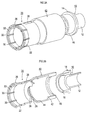
- FIG. 2A is a cross-sectional view of the coaxial cable connector showing a state where the opening end side of the fitting portion of the coaxial cable connector is expanded, and FIG. 2B shows a state where the diameter of the opening end side of the fitting portion is reduced.
- FIG. 3A is an exploded perspective view of the coaxial cable connector, and FIG. 3B is a partially broken perspective view showing a state in which components of the coaxial cable connector are cut along a plane along the central axis. It is sectional drawing showing the structure of the coaxial cable connector which provided the leaf
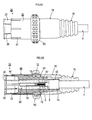
- FIG. 6A is a side view showing the appearance of a coaxial cable connector having a rod-like terminal crimped to the core wire of the coaxial cable and having a slit formed in the slide ring
- FIG. 6B is a cross-sectional view showing the internal configuration of the coaxial connector. It is. It is explanatory drawing showing the structure of the coaxial cable connector formed in the L shape.
- the coaxial cable connector of this embodiment is for connecting a coaxial cable 4 to an F-type plug 2 that constitutes a TV terminal, an antenna terminal, or the like.
- the connector main body 10 for connecting the coaxial cable 4, and the plug connection part 20 for connecting the F-type plug 2 are provided.
- the connector main body 10 includes a cylindrical insertion portion 12 that can be inserted between the insulating member 6 around the core wire 5 of the coaxial cable 4 and the outer conductor 7 around the insulating member 6. Then, when the insertion portion 12 is inserted into the coaxial cable 4, the outer conductor 7 of the coaxial cable 4 or the covering member 8 around the outer conductor 7 is brought into contact with the rear end side of the insertion portion 12. A flange portion 14 for positioning 12 (and thus the connector main body 10) at the tip of the coaxial cable 4 is formed. In addition, a cylindrical fixing portion 16 for fixing the plug connection portion 20 is formed on the opposite side of the flange portion 14 from the insertion portion 12.
- fixed part 16 which comprise the connector main body 10 are integrally formed with the electroconductive metal (for example, C3604B).
- the inner diameter of the fixing portion 16 is larger than the inner diameter of the insertion portion 12. This is because the insulating member 6 of the coaxial cable 4 inserted into the insertion portion 12 can be inserted into the plug connection portion 20 side.
- the plug connection portion 20 includes a cylindrical fitting portion 22 into which the F-type plug 2 can be inserted, and on the side opposite to the opening end of the fitting portion 22 on the F-type plug 2 side.
- a wall portion 26 having an insertion hole 24 through which the insulating member 6 of the coaxial cable 4 can be inserted is provided, and the fixing portion 16 of the connector body 10 is provided on the opposite side of the wall portion 26 from the fitting portion 22.
- a cylindrical fixing portion 28 to be fitted and fixed is projected.
- fixed part 28 which comprise the plug connection part 20 are integrally formed with the electroconductive metal (for example, C3604B) similarly to the connector main body 10.
- fixed part 16 adhere by press fit.
- the insulating member 6 extends from the tips of the covering member 8 and the outer conductor 7 by the length in the central axis direction of the fixed portion 16 and the wall portion 26.
- the end of the coaxial cable 4 is processed so as to protrude from the tip of the insulating member 6 by the length of the fitting portion 22, and the insertion portion 12 is connected to the outer conductor 7 of the coaxial cable and the insulating member 6. If it inserts in between, the terminal structure which surrounded the core wire 5 of the coaxial cable 4 with the fitting part 22 can be made.
- the fitting portion 22 is attached to the F-type plug 2 constituting a TV terminal or the like, the core wire 5 of the coaxial cable 4 is connected to the central conductor of the F-type plug 2 and is coaxial.
- the outer conductor 7 of the cable 4 is connected to the outer conductor of the F-type plug 2 via the fitting portion 22.
- the coaxial cable connector is easily detached from the F-type plug 2 only by attaching the fitting portion 22 to the F-type plug 2. Therefore, in this embodiment, the opening end side of the fitting portion 22 is formed in a tapered shape that spreads outward, and the fitting portion 22 (and thus the coaxial cable connector) is formed on the tapered portion. By forming a plurality of slits 30 along the central axis, the opening end side of the fitting portion 22 is radially divided into a plurality from the central axis.
- the opening end side of the fitting portion 22 is urged from the periphery by dividing the opening end side of the fitting portion 22 into a plurality of portions through the slits in this way, the opening end of the fitting portion 22 is opened.
- the side diameter is reduced so that the fitting portion 22 can be firmly fixed to the outer conductor of the F-type plug 2.
- the inner wall on the opening end side of the fitting portion 22 has a circumferential direction so as to engage with a thread formed around the outer conductor of the F-type plug 2 when the opening end is reduced in diameter.
- the formed protrusion 32 is provided.
- a slide ring 40 formed in a cylindrical shape with a conductive metal (for example, C3604B) is provided around the fitting portion 22.
- the slide ring 40 is connected in the axial direction so as to surround the region from the region where the slit 30 of the fitting portion 22 is not formed to the flange portion 14 in a state where the connector main body 10 and the plug connection portion 20 are connected.
- the length is set, and the inner diameter is substantially the same as or slightly larger than the outer diameter of a region where the slit 30 of the fitting portion 22 is not formed (region not formed in a tapered shape).
- a pair of protrusions 42 formed in the central axis direction from the collar part side are provided on the inner wall of the slide ring 40, and these protrusions 42 are engaged with the rear end side of the fitting part 22.
- a notch 38 is formed to guide the slide ring 40 so as to be movable toward the opening end side.
- a pair of protrusions 36 and 44 are provided along the circumferential direction of the opening end side outer wall of the fitting portion 22 and the opening end side inner wall of the slide ring 40.
- the protrusions 36 and 44 are brought into contact with each other before the slide ring 40 reaches the most distal end of the fitting portion 22.
- the protrusion 44 gets over the protrusion 36 of the fitting portion 22, and the slide ring 40 is prevented from moving in the reverse direction.
- the inner wall on the rear end side of the slide ring 40 is brought into contact with the rear end of the fitting portion 22 at a position where the tip of the slide ring 40 reaches the opening end of the fitting portion 22.
- a protrusion (protrusion) 46 that prevents movement toward the distal end side is provided.
- the outer peripheral surface on the opening end side of the fitting portion 22 is moved by the slide ring 40.
- the portion of the fitting portion 22 divided by the slit 30 is displaced toward the central axis, and the diameter of the fitting portion 22 on the opening end side is reduced.
- the diameter on the opening end side of the fitting portion 22 can be enlarged / reduced only by the slide ring 40.
- the configuration is simple and can be realized at low cost.
- the slide ring 40 is formed of a conductive metal in a cylindrical shape, the coaxial cable connector is attached to the F-type plug 2 and the slide ring 40 is moved to the opening end side of the fitting portion 22.
- the opening end side of the fitting portion 22 be reduced in diameter to be firmly fixed to the F-type plug 2, but the slit 30 formed on the opening end side of the fitting portion 22 can be moved by the slide ring 40. It is possible to prevent noise from entering through the enclosure and the slit 30.
- the opening end side outer wall of the fitting portion 22 is used to position the slide ring 40 when the slide ring 40 moves to the tip end position on the opening end side of the fitting portion 22.
- protrusions 36 and 44 that can be engaged with each other are provided.
- the coaxial cable connector is attached to the F-type plug, and the slide ring 40 is moved to the opening end side of the fitting portion, whereby the coaxial cable 4 is F-type.
- the slide ring 40 can be positioned at a fixed position to the F-type plug 2 by engaging the pair of protrusions 36 and 44.
- the protrusion 44 on the slide ring 40 side gets over the protrusion 36 on the fitting part 22 side, so that the open end of the fitting part 22 is obtained.
- Spreads outward and the ridge 36 abuts against the inner wall of the slide ring 40, so that sound and vibration are generated.
- the operator of the slide ring 40 can detect that the slide ring 40 has been moved to the most advanced position by sound or vibration, and the usability can be improved.
- the leaf spring 50 allows the outer conductor of the coaxial plug and the fitting portion 22 to be in surface contact with each other to ensure a shielding property, and the urging force of the leaf spring 50 allows the fitting.
- the portion 22 can be firmly fixed by the coaxial connector.
- a number of substantially parallel slits are formed in a metal plate as a spring material, and every other plate portion between the slits is formed. It is good to use what was press-molded so that it may protrude in a direction, and was made into the cylinder shape by winding a metal plate in the arrangement direction of a slit so that the protrusion direction might become inside.
- a ring cover 60 made of a synthetic resin for example, soft PVC
- a protrusion in the drawing, formed in the circumferential direction for positioning and fixing the ring cover 60 on the outer peripheral surface on the rear end side of the slide ring 40. 48).
- the axial length of the ring cover 60 is determined by, for example, attaching the fitting portion 22 to a television terminal (F-type plug 2) provided in a concave portion of a wall surface of a building as shown in FIG.
- the ring cover 60 may be appropriately set according to the place where the coaxial cable connector is used so that it does not hit the wall surface of the building.
- the slide ring 40 has been described as being simply formed in a cylindrical shape, but the coaxial cable 4 is connected to the slide ring 40 as in the coaxial cable connector shown in FIGS. 6A and 6B.
- the length in the central axis direction is shorter than the slit 30 of the fitting portion 22 and overlaps the slit 30 of the fitting portion 22.
- a plurality of slits may be formed so that there is no such a problem.
- the slit 41 of the slide ring 40 is shorter than the slit 30 of the fitting part 22 and does not overlap with the slit 30, it fits like the slide ring 40 of the above embodiment in which the slit 41 is not provided.
- Each projecting piece divided by the slit 30 in the joint portion 22 can be urged from the outside to reduce the diameter of the opening end of the fitting portion 22 and close the slit 30 formed in the fitting portion 22. The inside can be shielded.
- the ring cover 60 is provided on the slide ring 40, but this ring cover does not block the slit 41, and the coaxial cable 4 side of the slide ring 40. That is, it is provided at the end of the connector main body 10 side.
- the coaxial cable connector described in the embodiment and the first and second modifications has a structure in which the core wire 5 of the coaxial cable 4 is directly projected into the fitting portion 22 (see FIGS. 1 to 5).
- the axial length of the connector body 10 formed in a cylindrical shape with a metal material is made longer than that shown in FIGS.
- the insulating member 65 is provided in the inner space, and the rod-shaped terminal 70 to which the core wire 5 of the coaxial cable 4 is crimped is held via the insulating member 65, so that the tip of the rod-shaped terminal 70 is a so-called center conductor. As shown in FIG.
- the core wire 5 of the coaxial cable 4 can be inserted and crimped to the intermediate portion or the tip portion in the axial direction of the rod-shaped terminal 70.
- a crimping portion 72 having a larger diameter and having a hole for inserting a core wire formed from the rear end side is formed.
- This recess 67 eliminates the mismatch of transmission impedance that occurs at the crimped portion between the core wire 5 of the coaxial cable 4 and the rod-shaped terminal 70, and deteriorates the transmission characteristics of the transmission path formed through the coaxial cable connector. It is for preventing.
- the outer conductor of the coaxial cable 4 is connected to an annular connection member 7a that is externally fitted to the distal end portion of the coaxial cable 4, and the connection member 7a. Is connected to the connector main body 10 by being fitted inside the cable connection portion 13 formed at the end opposite to the fitting portion 22 of the connector main body 10.
- the connecting portion between the cable connecting portion 13 and the coaxial cable 4 is provided with a synthetic resin bush 76 that protects the connecting portion, and the connecting portion between the bush 76 and the connector body 10 is a synthetic portion. It is protected by an overmold 78 formed by resin injection molding.
- the coaxial cable connector of Modification 3 shown in FIGS. 6A and 6B is integrally assembled at the tip of the coaxial cable 4 using the bush 76 and the overmold 78. For this reason, the coaxial cable connector does not come off from the coaxial cable 4, and this also improves the reliability of the coaxial cable connector.
- the amount of movement of the slide ring 40 in the axial direction is the wall portion 43 formed at the end opposite to the fitting portion 22 of the slide ring 40. Is regulated by contacting the stepped portion 18 formed on the outer peripheral surface of the insulating member 65 or the fitting portion side end portion of the overmold 78.
- the protrusion 44 is provided in the internal peripheral surface of the fitting part 22 side opening end of the slide ring 40, the slide ring 40 moves to the fitting part 22 side, and the wall part 43 of the rear end is formed.
- the protrusion 44 goes over the opening end of the fitting portion 22, so that the opening end of the fitting portion 22 spreads outward and protrudes from the opening end surface.
- the strip 44 is engaged, and the slide ring 40 is positioned at that position.
- the opening end of the fitting portion 22 spreads outward, and comes into contact with the inner wall of the slide ring 40, so that sound and vibration are generated, and the user moves the slide ring 40 to the top. That the movement to the tip position can be detected by sound or vibration.
- the linear coaxial cable connector in which the central axis of the coaxial cable 4 and the central axis of the fitting portion 22 are formed in a straight line has been described. Even the coaxial cable connector formed in an L shape so that the central axis of the coaxial cable 4 and the central axis of the fitting portion 22 are orthogonal to each other can be applied in the same manner as described above.
- the plug connection portion 20 is constituted by the fitting portion 22 and the slide ring 40 as in the coaxial cable connector shown in FIGS. 6A and 6B.
- the tip shape of the protrusion 32 provided on the inner wall on the opening end side of the fitting portion 22 may be sharp or rounded.
- this protrusion 32 shall be provided in the inner peripheral whole region of the fitting part 22, it is provided only in the one part protrusion piece divided
- FIG. Also good.
- the protruding piece not provided with the protrusion 32 is not formed into a taper shape extending outward, but is formed into a straight shape extending straight in the axial direction, or the angle extending outward is reduced. May be.
- the protrusion 32 was demonstrated as what is cyclically
- the protrusion 42 provided on the inner wall of the slide ring 40 and the movement of the slide ring 40 by engaging with the protrusion 42 are provided.
- the guiding notch 38 is not necessarily provided and may be omitted.
- the distal end portion of the insertion portion 12 has a cylindrical shape with the same outer diameter, but is inserted into the coaxial cable 4.
- the outer periphery of the insertion portion 12 is tapered so that the outer diameter decreases toward the distal end side, and the diameter is once increased and tapered at the tip. Also good.
- Such a taper may be formed in a plurality of stages in the axial direction.
Abstract
A coaxial cable connector is provided with a connector body that is composed of cylindrically-formed conductive metal, and a cylindrical intermeshing section composed of conductive metal. The intermeshing section is configured so that the opening-end side, which is the opposite side of the connector body, is formed to be taper-shaped, wherein the diameter widens towards the outer direction; and the opening-end side is enabled to have its diameter shortened, by having the tapered section divided into multiple portions, by multiple slots, which are formed starting from the opening-end side and formed along the center axis of the intermeshing section. Provided around the intermeshing section is a slide ring that is composed of cylindrically-formed conductive metal, and which is bi-directionally movable along the center axis of the intermeshing section, from the connector body side to the opening-end side that has the slits formed, or in the opposite direction.
Description
本発明は、同軸ケーブルの端部に装着されて、同軸ケーブルをテレビ端子等の同軸接栓に接続するための同軸ケーブルコネクタに関する。
The present invention relates to a coaxial cable connector that is attached to an end of a coaxial cable and connects the coaxial cable to a coaxial plug such as a television terminal.
従来、建造物の壁面に設置されたテレビ端子や、各種受信機器に設けられたアンテナ端子には、同軸型で外部導体側が突出され、その外周面にねじ山が形成されたF型接栓が使用されている。
Conventionally, television terminals installed on the walls of buildings and antenna terminals provided on various receivers have F-type plugs that are coaxial and project on the outer conductor side and are threaded on the outer peripheral surface. in use.
そして、この種のF型接栓に同軸ケーブルを接続するための同軸ケーブルコネクタとしては、同軸ケーブルの芯線の周囲の絶縁部材と絶縁部材の周囲の外部導体との間に挿入される筒状の挿入部と、挿入部を同軸ケーブルに挿入した際に外部導体若しくは外部導体周囲の被覆部材に当接されて同軸ケーブルを位置決めする鍔部と、挿入部の同軸ケーブル側とは反対側に設けられてF型接栓の外部導体に嵌合(外嵌)可能な嵌合部と、から構成されたものが知られている。
And as a coaxial cable connector for connecting a coaxial cable to this kind of F-type plug, a cylindrical shape inserted between an insulating member around the core wire of the coaxial cable and an outer conductor around the insulating member Provided on the side opposite the coaxial cable side of the insertion portion, the flange portion that contacts the outer conductor or a covering member around the outer conductor when the insertion portion is inserted into the coaxial cable, and positions the coaxial cable And a fitting portion that can be fitted (externally fitted) to the outer conductor of the F-type connector.
また、この同軸ケーブルコネクタには、挿入部に対し嵌合部を回転可能に固定し、嵌合部の内周面に、F型接栓の外部導体周囲に形成されたねじ山と螺合可能なねじ山を形成したものと、嵌合部の内周面にはねじ山は形成せず、単に嵌合部内にF型接栓の外部導体を挿入するようにしたものと、の2種類が知られている。
In addition, the coaxial cable connector has a fitting portion rotatably fixed to the insertion portion, and can be screwed onto the inner peripheral surface of the fitting portion with a thread formed around the outer conductor of the F-type plug. There are two types: a thread formed on the inner peripheral surface of the fitting part and a threaded part not inserted on the inner peripheral surface of the fitting part, and the outer conductor of the F-type plug inserted into the fitting part. Are known.
この内、前者のものは、F型接栓の外部導体側に形成されたねじ山を利用して、同軸ケーブルをF型接栓にしっかりと固定できるようになるが、F型接栓への装着時に嵌合部を回転させる必要があるため、使用できないことがあった。
Of these, the former can use the thread formed on the outer conductor side of the F-type plug to fix the coaxial cable firmly to the F-type plug. Since it is necessary to rotate a fitting part at the time of mounting | wearing, it could not be used.
つまり、テレビ端子やアンテナ端子として使用されるF型接栓は、外部導体側が突出されることから、その設置箇所(つまり、建造物の壁面や受信機器の筐体)には、F型接栓が外に突出することのないよう凹部が形成されることがある。しかし、この場合、F型接栓周囲のスペースが狭いと、同軸ケーブルコネクタを装着する際に嵌合部を回転させることができないため、上記前者の同軸ケーブルコネクタは、使用することができなくなる。
In other words, since the F-type plug used as a TV terminal or antenna terminal protrudes from the outer conductor side, the F-type plug at the installation location (that is, the wall of the building or the housing of the receiving device). A recess may be formed so as not to protrude outward. However, in this case, if the space around the F-type plug is small, the fitting portion cannot be rotated when the coaxial cable connector is mounted, and thus the former coaxial cable connector cannot be used.
一方、嵌合部の内周面にねじ山を形成せず、嵌合部内にF型接栓の外部導体を挿入するようにした同軸ケーブルコネクタは、嵌合部を回転させる必要がないので、構造が簡単になり、しかも、F型接栓が凹部に設けられていても、F型接栓に簡単に装着することができる。
On the other hand, the coaxial cable connector in which the outer conductor of the F-type plug is inserted into the fitting portion without forming a screw thread on the inner peripheral surface of the fitting portion, so there is no need to rotate the fitting portion. The structure becomes simple, and even if the F-type plug is provided in the recess, it can be easily attached to the F-type plug.
しかし、この種の同軸ケーブルコネクタは、F型接栓に装着する際には、F型接栓の外部導体を嵌合部に挿入するだけであるため、一旦装着しても、同軸ケーブルの移動(引っ張り)等によって外れ易くなる。このため、例えば、テレビ端子と録画装置との接続に利用した際、予約録画時にその接続が外れていて、録画できなかった、というような不具合が生じ易くなり、このような不具合が生じることのないよう、信頼性を向上することが望まれていた。
However, when this type of coaxial cable connector is attached to the F-type plug, only the outer conductor of the F-type plug is inserted into the fitting portion. It becomes easy to come off by (pull) or the like. For this reason, for example, when it is used for the connection between the TV terminal and the recording device, a problem such that the connection has been disconnected at the time of scheduled recording and the recording could not be performed easily occurs, and such a problem may occur. It has been desired to improve reliability so that there is no problem.
そして、この要望に応えるために、従来では、嵌合部の開口端側にスリットを形成することで、嵌合部の開口端側の径を拡大/縮小できるようにし、その嵌合部の開口端側周囲にリングばねと、リングばねを嵌合部の軸方向に移動させるスライド・カラーとを設けることが提案されている(例えば、特許文献1等参照)。
In order to meet this demand, conventionally, a slit is formed on the opening end side of the fitting portion so that the diameter on the opening end side of the fitting portion can be enlarged / reduced. It has been proposed to provide a ring spring around the end side and a slide collar that moves the ring spring in the axial direction of the fitting portion (see, for example, Patent Document 1).
そして、この提案の同軸ケーブルコネクタによれば、嵌合部の開口端側の径を拡大/縮小できるので、嵌合部の開口部を広げた状態で、同軸ケーブルコネクタをF型接栓に装着し、その後、嵌合部の開口端を縮径させることによって、同軸ケーブルコネクタ(延いては同軸ケーブル)をF型接栓にしっかりと固定できるようになる。
In addition, according to the proposed coaxial cable connector, the diameter of the opening end side of the fitting portion can be enlarged / reduced, so that the coaxial cable connector is attached to the F-type plug with the opening portion of the fitting portion widened. Then, by reducing the diameter of the opening end of the fitting portion, the coaxial cable connector (and thus the coaxial cable) can be firmly fixed to the F-type plug.
しかしながら、上記提案の同軸ケーブルコネクタにおいては、嵌合部の開口端の径を拡大/縮小させるために、リングばねとスライド・カラーとを用いることから、構成が複雑になるという問題があった。
However, the proposed coaxial cable connector has a problem in that the configuration is complicated because a ring spring and a slide collar are used to enlarge / reduce the diameter of the opening end of the fitting portion.
また、スライド・カラーは、単にリングばねを移動させるためのものであるため、嵌合部の開口端側に形成したスリットを電気的に遮蔽することができず、スリットを通ってノイズが侵入することがあった。
Moreover, since the slide collar is merely for moving the ring spring, the slit formed on the opening end side of the fitting portion cannot be electrically shielded, and noise enters through the slit. There was a thing.
本発明は、こうした問題に鑑みなされたもので、同軸ケーブルをテレビ端子やアンテナ端子等のF型接栓にしっかりと固定することができ、しかも、構成が簡単でノイズの侵入を確実に防止することのできる同軸ケーブルコネクタを提供することを目的とする。
The present invention has been made in view of these problems. The coaxial cable can be firmly fixed to an F-type plug such as a television terminal or an antenna terminal, and the structure is simple and noise can be reliably prevented. An object of the present invention is to provide a coaxial cable connector that can be used.
かかる目的を達成するためになされた本発明の第1局面は、同軸ケーブルコネクタであって、筒状に形成された導電性金属で構成され、一方の開口端側が同軸ケーブルの外部導体と接続可能に形成され、内部空間内に、前記同軸ケーブルの芯線若しくは該芯線に接続された棒状端子を挿通可能なコネクタ本体と、導電性金属で構成され、前記コネクタ本体の前記同軸ケーブルとは反対側の開口端に設けられ、接続対象となる同軸接栓を挿嵌可能な筒状の嵌合部と、を備え、
前記嵌合部は、前記コネクタ本体とは反対側の開口端側が、外方向に向かって径が広がるテーパ状に形成され、しかも、そのテーパ部分が、開口端側から当該嵌合部の中心軸に沿って形成された複数のスリットによって複数に分割されることにより、開口端側が縮径可能に構成され、
前記嵌合部の周囲には、筒状に形成された導電性金属で構成され、前記コネクタ本体側から前記スリットが形成された開口端側若しくはその逆方向へと、当該嵌合部の中心軸に沿って双方向に移動可能なスライドリングが設けられていることを特徴とする。 A first aspect of the present invention made to achieve the above object is a coaxial cable connector, which is composed of a conductive metal formed in a cylindrical shape, and one open end side can be connected to an outer conductor of the coaxial cable. A connector main body through which the core wire of the coaxial cable or a rod-shaped terminal connected to the core wire can be inserted into the internal space, and a conductive metal, and the connector main body is opposite to the coaxial cable. A cylindrical fitting portion that is provided at the opening end and can be fitted with a coaxial plug to be connected;
The fitting part is formed in a tapered shape whose opening end side opposite to the connector body has a diameter increasing outwardly, and the taper part extends from the opening end side to the central axis of the fitting part. Is divided into a plurality of slits formed along a plurality of slits, so that the opening end side can be reduced in diameter.
The periphery of the fitting portion is made of a conductive metal formed in a cylindrical shape, and the center axis of the fitting portion from the connector body side to the opening end side where the slit is formed or in the opposite direction. Is provided with a slide ring that is movable in both directions.
また、本発明の第2局面は、第1局面の同軸ケーブルコネクタであって、前記嵌合部の開口端側内周面には、前記同軸接栓の外周面に形成されたねじ山に係合可能な突条が形成されていることを特徴とする。
Further, the second aspect of the present invention is the coaxial cable connector according to the first aspect, wherein the opening end side inner peripheral surface of the fitting portion is related to a thread formed on the outer peripheral surface of the coaxial plug. It is characterized in that a projecting ridge is formed.
次に、本発明の第3局面は、第1局面又は第2局面の同軸ケーブルコネクタであって、前記スライドリングの内周面及び前記嵌合部の外周面の少なくとも一方に、前記スライドリングが前記嵌合部の開口端側に移動されて前記嵌合部を縮径させた特定位置にて、前記嵌合部側若しくは前記スライドリング側の係合部と係合して、前記スライドリングを位置決めする係合突起が形成されていることを特徴とする。
Next, a third aspect of the present invention is the coaxial cable connector according to the first aspect or the second aspect, wherein the slide ring is provided on at least one of an inner peripheral surface of the slide ring and an outer peripheral surface of the fitting portion. The slide ring is engaged with the engagement portion on the fitting portion side or the slide ring side at a specific position moved to the opening end side of the fitting portion to reduce the diameter of the fitting portion. An engaging projection for positioning is formed.
また、本発明の第4局面は、第3局面の同軸ケーブルコネクタであって、前記嵌合部の外周面に形成される係合部は、前記スライドリングが前記嵌合部の開口端側に移動されてスライドリングの係合部と係合する際、前記嵌合部の開口端が拡縮してスライドリングの内周面に当たり、音を発生するよう、前記嵌合部の開口端近傍に形成されていることを特徴とする。
Further, a fourth aspect of the present invention is the coaxial cable connector according to the third aspect, wherein the engaging portion formed on the outer peripheral surface of the fitting portion has the slide ring on the opening end side of the fitting portion. Formed in the vicinity of the opening end of the fitting portion so that when it is moved and engaged with the engaging portion of the slide ring, the opening end of the fitting portion expands and contracts and hits the inner peripheral surface of the slide ring to generate sound It is characterized by being.
また次に、本発明の第5局面は、第1局面から第4局面の何れか1つの同軸ケーブルコネクタであって、前記スライドリングの周囲には、樹脂製のリングカバーが設けられていることを特徴とする。
Next, a fifth aspect of the present invention is the coaxial cable connector according to any one of the first to fourth aspects, wherein a resin ring cover is provided around the slide ring. It is characterized by.
また、本発明の第6局面は、第5局面の同軸ケーブルコネクタであって、前記スライドリングには、前記コネクタ本体とは反対側の開口端からコネクタ本体側に向かって、前記嵌合部のスリットよりも短く、且つ、前記嵌合部のスリットと重なることのないよう、複数のスリットが形成されており、前記リングカバーは、前記スライドリングのコネクタ本体側の端部に設けられていることを特徴とする。
Further, a sixth aspect of the present invention is the coaxial cable connector according to the fifth aspect, wherein the slide ring includes the fitting portion that is directed from the opening end opposite to the connector body toward the connector body. A plurality of slits are formed so as to be shorter than the slits and not overlap with the slits of the fitting portion, and the ring cover is provided at the end of the slide ring on the connector main body side. It is characterized by.
また、本発明の第7局面は、第1局面から第6局面の何れか1つの同軸ケーブルコネクタであって、前記コネクタ本体の内部空間内には、同軸ケーブルの芯線が圧着された棒状端子を前記嵌合部内に突出させた状態で保持する絶縁性部材が設けられており、
前記コネクタ本体の内周面に接する前記絶縁性部材の外周面において、前記同軸ケーブルの芯線と棒状端子との圧着部分に対応する位置には、前記コネクタ本体の内周面との間で空間を形成する凹部が形成されていることを特徴とする。 Further, a seventh aspect of the present invention is the coaxial cable connector according to any one of the first to sixth aspects, wherein a rod-like terminal to which a core wire of the coaxial cable is crimped is provided in the internal space of the connector body. An insulative member is provided for holding in a state of protruding into the fitting portion,
On the outer peripheral surface of the insulating member in contact with the inner peripheral surface of the connector main body, a space is formed between the inner peripheral surface of the connector main body at a position corresponding to the crimped portion between the core wire and the rod-shaped terminal of the coaxial cable. A recess to be formed is formed.
また、本発明の第8局面は、第1局面から第7局面の何れか1つの同軸ケーブルコネクタであって、前記嵌合部には、当該嵌合部内に前記同軸接栓を挿入した際、当該嵌合部の内周面と前記同軸接栓の外周面との間に配設されて同軸接栓の外周面を付勢する板ばねが設けられていることを特徴とする。
Further, an eighth aspect of the present invention is the coaxial cable connector according to any one of the first to seventh aspects, wherein when the coaxial plug is inserted into the fitting portion, A leaf spring is provided between the inner peripheral surface of the fitting portion and the outer peripheral surface of the coaxial plug, and biases the outer peripheral surface of the coaxial plug.
第1局面の同軸ケーブルコネクタでは、嵌合部のコネクタ本体とは反対側の開口端側が、外方向に向かって径が広がるテーパ状に形成され、しかも、そのテーパ部分が、開口端側から当該嵌合部の中心軸に沿って形成された複数のスリットによって複数に分割されている。
In the coaxial cable connector according to the first aspect, the opening end side opposite to the connector main body of the fitting portion is formed in a tapered shape whose diameter increases outward, and the tapered portion extends from the opening end side. Divided into a plurality of slits by a plurality of slits formed along the central axis of the fitting portion.
そして、嵌合部の周囲には、筒状に形成された導電性金属で構成され、コネクタ本体側からスリットが形成された開口端側若しくはその逆方向へと、当該嵌合部の中心軸に沿って双方向に移動可能なスライドリングが設けられている。
And the periphery of the fitting portion is made of a conductive metal formed in a cylindrical shape, from the connector main body side to the opening end side where the slit is formed, or in the opposite direction, to the central axis of the fitting portion. A slide ring is provided that can move in both directions along.
このため、本発明の同軸ケーブルコネクタによれば、このスライドリングを、コネクタ本体側からスリットが形成された開口端側へと移動させれば、テーパ状に形成された嵌合部の開口端側が縮径され、逆に、その開口端側からコネクタ本体側へと移動させれば、嵌合部の開口端側がテーパ状に広がり、その径が拡大することになる。
For this reason, according to the coaxial cable connector of the present invention, if the slide ring is moved from the connector main body side to the opening end side where the slit is formed, the opening end side of the fitting portion formed in a tapered shape is formed. If the diameter is reduced and conversely moved from the opening end side to the connector main body side, the opening end side of the fitting portion expands in a taper shape, and the diameter increases.
よって、嵌合部の開口端側の径を拡大/縮小させるためにリングばねとスライド・カラーとを設けた従来のものに比べて、構成が簡単になり、低コストで実現できる。
また、スライドリングは筒状に形成された導電性金属で構成されているので、同軸ケーブルコネクタを、同軸接栓に装着して、スライドリングを嵌合部の開口端側に移動させた際には、嵌合部の開口端側を縮径させて同軸接栓(上述のF型接栓等)に固定できるだけでなく、嵌合部の開口端側に形成されたスリットをスライドリングにて囲み、スリットを通ってノイズが侵入するのを防止することができる。 Therefore, the configuration is simpler and can be realized at a lower cost than the conventional one in which the ring spring and the slide collar are provided in order to enlarge / reduce the diameter on the opening end side of the fitting portion.
In addition, since the slide ring is made of a conductive metal formed in a cylindrical shape, when the coaxial cable connector is attached to the coaxial connector and the slide ring is moved to the opening end side of the fitting portion, Not only can the diameter of the opening end of the fitting part be reduced and fixed to a coaxial plug (such as the F-type plug mentioned above), but the slit formed on the opening end side of the fitting part should be surrounded by a slide ring. , Noise can be prevented from entering through the slit.
次に、第2局面の同軸ケーブルコネクタによれば、嵌合部の開口端側内周面に、同軸接栓の外周面に形成されたねじ山に係合可能な突条が形成されていることから、同軸ケーブルコネクタを、同軸接栓に装着して、スライドリングを嵌合部の開口端側に移動させた際には、嵌合部の開口端が縮径するだけでなく、その開口端内周面に形成された突条が同軸接栓に形成されたねじ山と係合する。
Next, according to the coaxial cable connector of the second aspect, the protrusion that can be engaged with the thread formed on the outer peripheral surface of the coaxial plug is formed on the inner peripheral surface of the fitting end on the opening end side. Therefore, when the coaxial cable connector is attached to the coaxial connector and the slide ring is moved to the opening end side of the fitting portion, not only the opening end of the fitting portion is reduced in diameter but also the opening A protrusion formed on the inner peripheral surface of the end engages with a thread formed on the coaxial plug.
このため、第2局面の同軸ケーブルコネクタによれば、同軸ケーブルコネクタを同軸接栓に装着した際、嵌合部が同軸接栓から外れるのを防止し、同軸接栓に対して同軸ケーブルをより強固に固定することができる。
For this reason, according to the coaxial cable connector of the second aspect, when the coaxial cable connector is attached to the coaxial plug, the fitting portion is prevented from being detached from the coaxial plug, and the coaxial cable is more connected to the coaxial plug. It can be firmly fixed.
なお、突条は、嵌合部の中心軸周りに環状に形成してもよいが、より好ましくは、同軸接栓の外周面に形成されるねじ山の形状に対応して、螺旋状に形成するとよい。
そして、このようにすれば、突条を略全域でねじ山と係合させることができるので、同軸ケーブルコネクタが同軸接栓から外れるのをより確実に防止することができる。 The protrusion may be formed in an annular shape around the central axis of the fitting portion, but more preferably formed in a spiral shape corresponding to the shape of the thread formed on the outer peripheral surface of the coaxial plug. Good.
And if it does in this way, since a protrusion can be engaged with a screw thread in the substantially whole region, it can prevent more reliably that a coaxial cable connector remove | deviates from a coaxial plug.
次に、第3局面の同軸ケーブルコネクタによれば、スライドリングの内周面及び嵌合部の外周面の少なくとも一方に、スライドリングが嵌合部の開口端側に移動されて嵌合部を縮径させた特定位置で嵌合部側若しくはスライドリング側の係合部と係合して、スライドリングを位置決めする係合突起が形成されている。
Next, according to the coaxial cable connector of the third aspect, the slide ring is moved to the opening end side of the fitting portion on at least one of the inner peripheral surface of the slide ring and the outer peripheral surface of the fitting portion. Engagement protrusions for positioning the slide ring are formed by engaging with the engagement portion on the fitting portion side or the slide ring side at the reduced position.
このため、同軸ケーブルコネクタを同軸接栓に装着して、スライドリングを嵌合部の開口端側に移動させ、同軸ケーブルを同軸接栓に固定した際、係合突起によりスライドリングを位置決めして、スライドリングがコネクタ本体側に移動するのを防止できる。
Therefore, when the coaxial cable connector is attached to the coaxial connector, the slide ring is moved to the opening end side of the fitting portion, and the coaxial cable is fixed to the coaxial connector, the slide ring is positioned by the engaging protrusion. The slide ring can be prevented from moving toward the connector body.
また、同軸ケーブルコネクタを同軸接栓に装着して、スライドリングを嵌合部の開口端側に移動させた際、係合突起が係合部と係合すると音や振動が発生するので、スライドリングの操作者は、スライドリングが所定の固定位置まで移動できたことを検知できることになり、使い勝手を向上できる。
Also, when the coaxial cable connector is attached to the coaxial connector and the slide ring is moved to the opening end side of the fitting portion, noise and vibration are generated when the engagement protrusion engages with the engagement portion. The operator of the ring can detect that the slide ring has been moved to a predetermined fixed position, and the usability can be improved.
なお、このように係合部の係合状態を音で確認できるようにするには、第4局面のように、スライドリングが嵌合部の開口端側に移動されて係合突起が係合部と係合する際、嵌合部の開口端が係合突起の突出量に応じた量だけ開き(換言すれば拡縮し)、嵌合部がスライドリングの内周面に当接されて、音を発生するよう、係合部を、同軸接栓が挿入される開口端近傍に形成することが望ましい。
In addition, in order to make it possible to confirm the engagement state of the engagement portion with sound in this way, as in the fourth aspect, the slide ring is moved to the opening end side of the engagement portion, and the engagement protrusion is engaged. When engaging with the part, the opening end of the fitting part opens by an amount corresponding to the protruding amount of the engaging projection (in other words, expands and contracts), and the fitting part comes into contact with the inner peripheral surface of the slide ring, It is desirable to form the engaging portion in the vicinity of the opening end where the coaxial plug is inserted so as to generate sound.
また次に、第5局面の同軸ケーブルコネクタによれば、スライドリングの周囲に、樹脂製のリングカバーが設けられているため、使用者がスライドリングを手動で移動させる際には、リングカバーが滑り止めとなり、スライドリング操作時の使い勝手を向上できる。
Next, according to the coaxial cable connector of the fifth aspect, since the resin ring cover is provided around the slide ring, when the user manually moves the slide ring, the ring cover is It becomes slippery and can improve usability when operating the slide ring.
また、使用者がスライドリングを操作する際には、リングカバーが、スライドリングと使用者との間を電気的に絶縁することになるので、同軸ケーブルの外部導体に電気信号が流れていたとしても、その信号が使用者に伝わるのを防止し、安全性を向上できる。
In addition, when the user operates the slide ring, the ring cover electrically insulates the slide ring from the user, so that an electrical signal flows through the outer conductor of the coaxial cable. However, it is possible to prevent the signal from being transmitted to the user and improve safety.
一方、第6局面の同軸ケーブルコネクタにおいて、スライドリングには、コネクタ本体とは反対側の開口端からコネクタ本体側に向かって、嵌合部のスリットよりも短く、且つ、嵌合部のスリットと重なることのないよう、複数のスリットが形成されている。
On the other hand, in the coaxial cable connector of the sixth aspect, the slide ring is shorter than the slit of the fitting portion from the opening end opposite to the connector main body toward the connector main body side, A plurality of slits are formed so as not to overlap.
このため、第6局面の同軸ケーブルコネクタによれば、使用者がスライドリングを嵌合部の開口端側に移動させる際に、スライドリングの開口が広がって、スムーズに移動させることができるようになり、操作性を向上できる。
For this reason, according to the coaxial cable connector of the sixth aspect, when the user moves the slide ring to the opening end side of the fitting portion, the opening of the slide ring is widened and can be moved smoothly. Therefore, the operability can be improved.
また、スライドリングのスリットは、嵌合部のスリットよりも短く、しかも、嵌合部のスリットと重なることがないため、スリットで分割された嵌合部の開口端を外側から付勢して、嵌合部の開口端を縮径させることができ、上述したスライドリングの機能を損なうことはない。
Also, the slit of the slide ring is shorter than the slit of the fitting part, and does not overlap with the slit of the fitting part, so the opening end of the fitting part divided by the slit is urged from the outside, The diameter of the opening end of the fitting portion can be reduced, and the function of the slide ring described above is not impaired.
また、第6局面の同軸ケーブルコネクタにおいて、使用者がスライドリングを手動で移動させる際に用いられるリングカバーは、スライドリングのコネクタ本体側の端部に設けられることから、スライドリングに形成されたスリットを塞ぎ、その機能を損なうことを防止できる。
Further, in the coaxial cable connector of the sixth aspect, the ring cover used when the user manually moves the slide ring is formed at the end of the slide ring on the connector body side, and thus is formed on the slide ring. It is possible to prevent the slit from being blocked and impairing its function.
また、第7局面の同軸ケーブルコネクタにおいては、コネクタ本体の内部空間内に絶縁性部材が設けられており、この絶縁性部材にて、同軸ケーブルの芯線が圧着された棒状端子を嵌合部内に突出させた状態で保持するようにされている。
Further, in the coaxial cable connector of the seventh aspect, an insulating member is provided in the internal space of the connector body, and the rod-shaped terminal, to which the core wire of the coaxial cable is crimped, is fitted in the fitting portion by the insulating member. It is made to hold | maintain in the state made to protrude.
このため、第7局面の同軸ケーブルコネクタによれば、同軸接栓に装着した際、同軸ケーブルの芯線と、接続対象となる同軸接栓の中心導体とを、棒状端子を介して接続することができるようになり、同軸ケーブルの芯線を嵌合部内に突出させて、同軸接栓の中心導体に同軸ケーブルの芯線を直接接続するようにした場合に比べて、同軸接栓への接続時の信頼性を向上することができる。
For this reason, according to the coaxial cable connector of the seventh aspect, when the coaxial cable connector is attached to the coaxial plug, the core wire of the coaxial cable and the central conductor of the coaxial plug to be connected can be connected via the rod-shaped terminal. Compared with the case where the coaxial cable core wire is directly connected to the central conductor of the coaxial plug by projecting the coaxial cable core wire into the fitting section, the reliability when connecting to the coaxial plug is more reliable. Can be improved.
また、第7局面の同軸ケーブルコネクタによれば、コネクタ本体の内周面に接する絶縁性部材の外周面において、同軸ケーブルの芯線と棒状端子との圧着部分に対応する位置には、コネクタ本体の内周面との間で空間を形成する凹部が形成されていることから、この凹部の大きさを適宜設定することにより、同軸ケーブルの芯線と棒状端子との圧着部分で生じる伝送インピーダンスの不整合を解消し、当該同軸ケーブルコネクタを介して形成される伝送経路の伝送特性が劣化するのを防止できる。
According to the coaxial cable connector of the seventh aspect, on the outer peripheral surface of the insulating member in contact with the inner peripheral surface of the connector main body, a position corresponding to the crimping portion between the core wire of the coaxial cable and the rod-shaped terminal is Since a recess that forms a space between the inner peripheral surface and the inner peripheral surface is formed, by appropriately setting the size of the recess, mismatching of transmission impedance that occurs at the crimped portion between the core wire of the coaxial cable and the rod-shaped terminal It is possible to prevent the transmission characteristics of the transmission path formed via the coaxial cable connector from deteriorating.
また次に、第8局面の同軸ケーブルコネクタによれば、嵌合部の内部には、F型接栓等の同軸接栓が挿入された際に、その同軸接栓の外周面を付勢する板ばねが設けられているため、同軸接栓の外部導体と嵌合部とを面接触させてシールド性を確保することができる。
Next, according to the coaxial cable connector of the eighth aspect, when a coaxial plug such as an F-type plug is inserted into the fitting portion, the outer peripheral surface of the coaxial plug is biased. Since the leaf spring is provided, the outer conductor of the coaxial plug and the fitting portion can be brought into surface contact to ensure shielding properties.
2…F型接栓(同軸接栓)、4…同軸ケーブル、5…芯線、6…絶縁部材、7…外部導体、7a…接続部材、8…被覆部材、10…コネクタ本体、12…挿入部、13…ケーブル接続部、14…鍔部、16…固定部、18…段差部、20…接栓接続部、22…嵌合部、24…挿通孔、26…壁部、28…固定部、30…スリット、32,36…突条、38…切り欠き、40…スライドリング、41…スリット、42…突起、43…壁部、44,48…突条、50…板ばね、60…リングカバー、65…絶縁性部材、67…凹部、70…棒状端子、72…圧着部、76…ブッシュ、78…オーバーモールド。
2 ... F-type plug (coaxial plug), 4 ... coaxial cable, 5 ... core wire, 6 ... insulating member, 7 ... external conductor, 7a ... connecting member, 8 ... cover member, 10 ... connector body, 12 ... insertion portion , 13 ... cable connection part, 14 ... collar part, 16 ... fixing part, 18 ... step part, 20 ... plug connection part, 22 ... fitting part, 24 ... insertion hole, 26 ... wall part, 28 ... fixing part, 30 ... slit, 32, 36 ... protrusion, 38 ... notch, 40 ... slide ring, 41 ... slit, 42 ... protrusion, 43 ... wall, 44, 48 ... protrusion, 50 ... leaf spring, 60 ... ring cover , 65 ... insulating member, 67 ... recess, 70 ... rod-shaped terminal, 72 ... crimping part, 76 ... bush, 78 ... overmold.
以下に本発明の実施形態を図面と共に説明する。
図1,2A-2B,3A-3Bに示すように、本実施形態の同軸ケーブルコネクタは、テレビ端子やアンテナ端子等を構成するF型接栓2に同軸ケーブル4を接続するためのものであり(図2A参照)、同軸ケーブル4を接続するためのコネクタ本体10と、F型接栓2を接続するための接栓接続部20と、を備える。 Embodiments of the present invention will be described below with reference to the drawings.
As shown in FIGS. 1, 2A-2B, and 3A-3B, the coaxial cable connector of this embodiment is for connecting acoaxial cable 4 to an F-type plug 2 that constitutes a TV terminal, an antenna terminal, or the like. (Refer FIG. 2A), The connector main body 10 for connecting the coaxial cable 4, and the plug connection part 20 for connecting the F-type plug 2 are provided.
図1,2A-2B,3A-3Bに示すように、本実施形態の同軸ケーブルコネクタは、テレビ端子やアンテナ端子等を構成するF型接栓2に同軸ケーブル4を接続するためのものであり(図2A参照)、同軸ケーブル4を接続するためのコネクタ本体10と、F型接栓2を接続するための接栓接続部20と、を備える。 Embodiments of the present invention will be described below with reference to the drawings.
As shown in FIGS. 1, 2A-2B, and 3A-3B, the coaxial cable connector of this embodiment is for connecting a
この内、コネクタ本体10は、同軸ケーブル4の芯線5周囲の絶縁部材6と、その絶縁部材6周囲の外部導体7との間に挿入可能な筒状の挿入部12を備える。そして、挿入部12の後端側には、挿入部12を同軸ケーブル4に挿入した際に同軸ケーブル4の外部導体7若しくは外部導体7周囲の被覆部材8が当接されることにより、挿入部12(延いてはコネクタ本体10)を同軸ケーブル4の先端に位置決めする鍔部14が形成されている。また、鍔部14の挿入部12とは反対側には、接栓接続部20を固定するための筒状の固定部16が形成されている。
Among these, the connector main body 10 includes a cylindrical insertion portion 12 that can be inserted between the insulating member 6 around the core wire 5 of the coaxial cable 4 and the outer conductor 7 around the insulating member 6. Then, when the insertion portion 12 is inserted into the coaxial cable 4, the outer conductor 7 of the coaxial cable 4 or the covering member 8 around the outer conductor 7 is brought into contact with the rear end side of the insertion portion 12. A flange portion 14 for positioning 12 (and thus the connector main body 10) at the tip of the coaxial cable 4 is formed. In addition, a cylindrical fixing portion 16 for fixing the plug connection portion 20 is formed on the opposite side of the flange portion 14 from the insertion portion 12.
なお、コネクタ本体10を構成する挿入部12、鍔部14、固定部16は、導電性金属(例えば、C3604B)にて一体形成されている。また、固定部16の内径は、挿入部12の内径よりも大きくなっている。これは、挿入部12に挿入された同軸ケーブル4の絶縁部材6を接栓接続部20側へ挿通できるようにするためである。
In addition, the insertion part 12, the collar part 14, and the fixing | fixed part 16 which comprise the connector main body 10 are integrally formed with the electroconductive metal (for example, C3604B). In addition, the inner diameter of the fixing portion 16 is larger than the inner diameter of the insertion portion 12. This is because the insulating member 6 of the coaxial cable 4 inserted into the insertion portion 12 can be inserted into the plug connection portion 20 side.
一方、接栓接続部20は、F型接栓2を挿嵌可能な筒状の嵌合部22を備え、その嵌合部22のF型接栓2側の開口端とは反対側には、同軸ケーブル4の絶縁部材6を挿通可能な挿通孔24が形成された壁部26が設けられ、その壁部26の嵌合部22とは反対側には、コネクタ本体10の固定部16に嵌合固定される筒状の固定部28が突設されている。なお、接栓接続部20を構成する嵌合部22、壁部26、及び固定部28は、コネクタ本体10と同様、導電性金属(例えば、C3604B)にて一体形成されている。また、固定部28と固定部16は圧入によって固着する。
On the other hand, the plug connection portion 20 includes a cylindrical fitting portion 22 into which the F-type plug 2 can be inserted, and on the side opposite to the opening end of the fitting portion 22 on the F-type plug 2 side. A wall portion 26 having an insertion hole 24 through which the insulating member 6 of the coaxial cable 4 can be inserted is provided, and the fixing portion 16 of the connector body 10 is provided on the opposite side of the wall portion 26 from the fitting portion 22. A cylindrical fixing portion 28 to be fitted and fixed is projected. In addition, the fitting part 22, the wall part 26, and the fixing | fixed part 28 which comprise the plug connection part 20 are integrally formed with the electroconductive metal (for example, C3604B) similarly to the connector main body 10. FIG. Moreover, the fixing | fixed part 28 and the fixing | fixed part 16 adhere by press fit.
このため、本実施形態の同軸ケーブルコネクタは、図2Aに示すように、被覆部材8及び外部導体7の先端から、絶縁部材6が、固定部16及び壁部26の中心軸方向の長さ分だけ突出し、更に、絶縁部材6の先端から、嵌合部22の長さ分だけ突出するように、同軸ケーブル4の先端を加工し、挿入部12を、同軸ケーブルの外部導体7と絶縁部材6との間に挿入すれば、同軸ケーブル4の芯線5を嵌合部22で囲んだ端子構造にすることができる。
Therefore, in the coaxial cable connector of the present embodiment, as shown in FIG. 2A, the insulating member 6 extends from the tips of the covering member 8 and the outer conductor 7 by the length in the central axis direction of the fixed portion 16 and the wall portion 26. The end of the coaxial cable 4 is processed so as to protrude from the tip of the insulating member 6 by the length of the fitting portion 22, and the insertion portion 12 is connected to the outer conductor 7 of the coaxial cable and the insulating member 6. If it inserts in between, the terminal structure which surrounded the core wire 5 of the coaxial cable 4 with the fitting part 22 can be made.
そして、この状態で、嵌合部22を、テレビ端子等を構成しているF型接栓2に装着すれば、同軸ケーブル4の芯線5がF型接栓2の中心導体に接続され、同軸ケーブル4の外部導体7が嵌合部22を介してF型接栓2の外部導体に接続されることになる。
In this state, if the fitting portion 22 is attached to the F-type plug 2 constituting a TV terminal or the like, the core wire 5 of the coaxial cable 4 is connected to the central conductor of the F-type plug 2 and is coaxial. The outer conductor 7 of the cable 4 is connected to the outer conductor of the F-type plug 2 via the fitting portion 22.
しかし、嵌合部22をF型接栓2に装着しただけでは、同軸ケーブルコネクタがF型接栓2から外れ易い。
そこで、本実施形態では、嵌合部22の開口端側を、外方向に広がるテーパ状に形成し、そのテーパ状に形成された部分に、嵌合部22(延いては同軸ケーブルコネクタ)の中心軸に沿って複数のスリット30を形成することにより、嵌合部22の開口端側を、その中心軸から放射状に複数に分割している。 However, the coaxial cable connector is easily detached from the F-type plug 2 only by attaching the fitting portion 22 to the F-type plug 2.
Therefore, in this embodiment, the opening end side of thefitting portion 22 is formed in a tapered shape that spreads outward, and the fitting portion 22 (and thus the coaxial cable connector) is formed on the tapered portion. By forming a plurality of slits 30 along the central axis, the opening end side of the fitting portion 22 is radially divided into a plurality from the central axis.
そこで、本実施形態では、嵌合部22の開口端側を、外方向に広がるテーパ状に形成し、そのテーパ状に形成された部分に、嵌合部22(延いては同軸ケーブルコネクタ)の中心軸に沿って複数のスリット30を形成することにより、嵌合部22の開口端側を、その中心軸から放射状に複数に分割している。 However, the coaxial cable connector is easily detached from the F-
Therefore, in this embodiment, the opening end side of the
つまり、このように嵌合部22の開口端側を、スリットを介して複数に分割することで、嵌合部22の開口端側を周囲から付勢した際に、嵌合部22の開口端側の径が縮小して、嵌合部22がF型接栓2の外部導体にしっかりと固定できるようにされている。
That is, when the opening end side of the fitting portion 22 is urged from the periphery by dividing the opening end side of the fitting portion 22 into a plurality of portions through the slits in this way, the opening end of the fitting portion 22 is opened. The side diameter is reduced so that the fitting portion 22 can be firmly fixed to the outer conductor of the F-type plug 2.
そして、嵌合部22の開口端側の内壁には、開口端が縮径された際に、F型接栓2の外部導体の周囲に形成されたねじ山に係合するよう、周方向に形成された突条32が設けられている。
Then, the inner wall on the opening end side of the fitting portion 22 has a circumferential direction so as to engage with a thread formed around the outer conductor of the F-type plug 2 when the opening end is reduced in diameter. The formed protrusion 32 is provided.
また、嵌合部22の周囲には、導電性金属(例えば、C3604B)にて筒状に形成されたスライドリング40が設けられている。このスライドリング40は、コネクタ本体10と接栓接続部20とを接続した状態で、嵌合部22のスリット30が形成されていない領域から鍔部14迄の領域を囲むように、軸方向の長さが設定されており、内径は、嵌合部22のスリット30が形成されていない領域(テーパ状に形成されていない領域)の外径と略同じか少し大きくなっている。
Further, a slide ring 40 formed in a cylindrical shape with a conductive metal (for example, C3604B) is provided around the fitting portion 22. The slide ring 40 is connected in the axial direction so as to surround the region from the region where the slit 30 of the fitting portion 22 is not formed to the flange portion 14 in a state where the connector main body 10 and the plug connection portion 20 are connected. The length is set, and the inner diameter is substantially the same as or slightly larger than the outer diameter of a region where the slit 30 of the fitting portion 22 is not formed (region not formed in a tapered shape).
また、スライドリング40の内壁には、鍔部側から中心軸方向に形成された一対の突起42が設けられており、嵌合部22の後端側には、これら各突起42が係合されて、スライドリング40を開口端側に移動可能に案内する切り欠き38が形成されている。
In addition, a pair of protrusions 42 formed in the central axis direction from the collar part side are provided on the inner wall of the slide ring 40, and these protrusions 42 are engaged with the rear end side of the fitting part 22. Thus, a notch 38 is formed to guide the slide ring 40 so as to be movable toward the opening end side.
そして、嵌合部22の開口端側外壁及びスライドリング40の開口端側内壁には、その周方向に沿って、一対の突条36、44が設けられている。この突条36、44は、スライドリング40を嵌合部22の開口端側に移動させた際に、スライドリング40が嵌合部22の最先端に到達する手前で当接され、スライドリング40を更に最先端側に移動させると、突条44が嵌合部22の突条36を乗り越え、スライドリング40が逆方向に移動するのを阻止するように形成されている。
A pair of protrusions 36 and 44 are provided along the circumferential direction of the opening end side outer wall of the fitting portion 22 and the opening end side inner wall of the slide ring 40. When the slide ring 40 is moved to the opening end side of the fitting portion 22, the protrusions 36 and 44 are brought into contact with each other before the slide ring 40 reaches the most distal end of the fitting portion 22. When the rod is further moved to the most distal side, the protrusion 44 gets over the protrusion 36 of the fitting portion 22, and the slide ring 40 is prevented from moving in the reverse direction.
また、スライドリング40の後端側の内壁には、スライドリング40の先端が嵌合部22の開口端に達した位置で、嵌合部22の後端に当接されて、スライドリング40の先端側への移動を阻止する突起(突条)46が設けられている。
Further, the inner wall on the rear end side of the slide ring 40 is brought into contact with the rear end of the fitting portion 22 at a position where the tip of the slide ring 40 reaches the opening end of the fitting portion 22. A protrusion (protrusion) 46 that prevents movement toward the distal end side is provided.
上記のように構成された本実施形態の同軸ケーブルコネクタによれば、スライドリング40を嵌合部22の開口端側に移動させると、スライドリング40により嵌合部22の開口端側の外周面がスライドリング40の内周面に当たって、嵌合部22のスリット30で分割された部分が中心軸に向けて変位し、嵌合部22の開口端側の径が縮小される。
According to the coaxial cable connector of the present embodiment configured as described above, when the slide ring 40 is moved to the opening end side of the fitting portion 22, the outer peripheral surface on the opening end side of the fitting portion 22 is moved by the slide ring 40. Hits the inner peripheral surface of the slide ring 40, the portion of the fitting portion 22 divided by the slit 30 is displaced toward the central axis, and the diameter of the fitting portion 22 on the opening end side is reduced.
そして、スライドリング40を、スライドリング40の突条44が嵌合部22の突条36を乗り越える最先端位置まで移動させると、スライドリング40が、これら各突条44、36の係合により位置決めされ、スライドリング40が鍔部14側に移動して、嵌合部22の開口端側の径が大きくなるのが防止される。
Then, when the slide ring 40 is moved to the most advanced position where the protrusion 44 of the slide ring 40 gets over the protrusion 36 of the fitting portion 22, the slide ring 40 is positioned by the engagement of the protrusions 44 and 36. Thus, the slide ring 40 is prevented from moving to the flange portion 14 side and the opening end side diameter of the fitting portion 22 is increased.
このように、本実施形態の同軸ケーブルコネクタによれば、スライドリング40だけで、嵌合部22の開口端側の径を拡大/縮小できるようにされているため、前述の従来技術に対して、構成が簡単になり、低コストで実現できる。
As described above, according to the coaxial cable connector of the present embodiment, the diameter on the opening end side of the fitting portion 22 can be enlarged / reduced only by the slide ring 40. The configuration is simple and can be realized at low cost.
また、スライドリング40は導電性金属にて筒状に形成されているので、同軸ケーブルコネクタをF型接栓2に装着して、スライドリング40を嵌合部22の開口端側に移動させた際には、嵌合部22の開口端側を縮径させてF型接栓2にしっかりと固定できるだけでなく、嵌合部22の開口端側に形成されたスリット30をスライドリング40にて囲み、スリット30を通ってノイズが侵入するのを防止することができる。
Further, since the slide ring 40 is formed of a conductive metal in a cylindrical shape, the coaxial cable connector is attached to the F-type plug 2 and the slide ring 40 is moved to the opening end side of the fitting portion 22. In this case, not only can the opening end side of the fitting portion 22 be reduced in diameter to be firmly fixed to the F-type plug 2, but the slit 30 formed on the opening end side of the fitting portion 22 can be moved by the slide ring 40. It is possible to prevent noise from entering through the enclosure and the slit 30.
また、本実施形態の同軸ケーブルコネクタにおいては、スライドリング40が嵌合部22の開口端側の先端位置に移動した際にスライドリング40を位置決めするために、嵌合部22の開口端側外壁及びスライドリング40の開口端側内壁に、互いに係合可能な突条36、44が設けられている。
In the coaxial cable connector of the present embodiment, the opening end side outer wall of the fitting portion 22 is used to position the slide ring 40 when the slide ring 40 moves to the tip end position on the opening end side of the fitting portion 22. On the opening end side inner wall of the slide ring 40, protrusions 36 and 44 that can be engaged with each other are provided.
このため、本実施形態の同軸ケーブルコネクタによれば、同軸ケーブルコネクタをF型接栓に装着して、スライドリング40を嵌合部の開口端側に移動させることにより、同軸ケーブル4をF型接栓2に固定した際には、上記一対の突条36、44を係合させることによって、スライドリング40を、F型接栓2への固定位置に位置決めすることができる。
Therefore, according to the coaxial cable connector of the present embodiment, the coaxial cable connector is attached to the F-type plug, and the slide ring 40 is moved to the opening end side of the fitting portion, whereby the coaxial cable 4 is F-type. When fixed to the plug 2, the slide ring 40 can be positioned at a fixed position to the F-type plug 2 by engaging the pair of protrusions 36 and 44.
また、このように突条36、44同士を係合させた際には、スライドリング40側の突条44が嵌合部22側の突条36を乗り越えることにより、嵌合部22の開放端が外方向に広がり、突条36がスライドリング40の内壁に当接されるので、音や振動が発生する。このため、スライドリング40の操作者は、スライドリング40を最先端位置まで移動できたことを音若しくは振動で検知できることになり、使い勝手を向上できる。
Further, when the protrusions 36 and 44 are engaged with each other in this manner, the protrusion 44 on the slide ring 40 side gets over the protrusion 36 on the fitting part 22 side, so that the open end of the fitting part 22 is obtained. Spreads outward and the ridge 36 abuts against the inner wall of the slide ring 40, so that sound and vibration are generated. For this reason, the operator of the slide ring 40 can detect that the slide ring 40 has been moved to the most advanced position by sound or vibration, and the usability can be improved.
以上、本発明の一実施形態について説明したが、本発明は、上記実施形態に限定されるものではなく、本発明の要旨を逸脱しない範囲内にて種々の態様をとることができる。
[変形例1]
例えば、図4Aに示すように、嵌合部22において、スリット30が形成されていない後端側の筒状部には、嵌合部22内にF型接栓2等の同軸接栓が挿入された際に、同軸接栓の外周面を付勢する板ばね50を設けるようにしてもよい。 As mentioned above, although one Embodiment of this invention was described, this invention is not limited to the said embodiment, A various aspect can be taken in the range which does not deviate from the summary of this invention.
[Modification 1]
For example, as shown in FIG. 4A, in thefitting portion 22, a coaxial plug such as an F-type plug 2 is inserted into the fitting portion 22 in the cylindrical portion on the rear end side where the slit 30 is not formed. When this is done, a leaf spring 50 that urges the outer peripheral surface of the coaxial connector may be provided.
[変形例1]
例えば、図4Aに示すように、嵌合部22において、スリット30が形成されていない後端側の筒状部には、嵌合部22内にF型接栓2等の同軸接栓が挿入された際に、同軸接栓の外周面を付勢する板ばね50を設けるようにしてもよい。 As mentioned above, although one Embodiment of this invention was described, this invention is not limited to the said embodiment, A various aspect can be taken in the range which does not deviate from the summary of this invention.
[Modification 1]
For example, as shown in FIG. 4A, in the
そして、このようにすれば、板ばね50により、同軸接栓の外部導体と嵌合部22とを面接触させてシールド性を確保することができると共に、板ばね50の付勢力によって、嵌合部22を同軸接栓により強固に固定することができるようになる。
In this way, the leaf spring 50 allows the outer conductor of the coaxial plug and the fitting portion 22 to be in surface contact with each other to ensure a shielding property, and the urging force of the leaf spring 50 allows the fitting. The portion 22 can be firmly fixed by the coaxial connector.
なお、この場合、板ばね50には、例えば、図4Bに示すように、ばね材となる金属板に、略平行なスリットを多数形成して、スリットの間の板部が一つ置きに一方向に突出するようプレス成形し、その突出方向が内側になるよう、金属板をスリットの配列方向に巻回して筒状にしたものを使用するとよい。
[変形例2]
また例えば、図5に示すように、スライドリング40の後端側外周面には、合成樹脂(例えば、軟質PVC)からなるリングカバー60を設けることで、使用者が、このリングカバー60を介して、スライドリング40を操作できるようにしてもよい。 In this case, for example, as shown in FIG. 4B, in theleaf spring 50, a number of substantially parallel slits are formed in a metal plate as a spring material, and every other plate portion between the slits is formed. It is good to use what was press-molded so that it may protrude in a direction, and was made into the cylinder shape by winding a metal plate in the arrangement direction of a slit so that the protrusion direction might become inside.
[Modification 2]
Further, for example, as shown in FIG. 5, aring cover 60 made of a synthetic resin (for example, soft PVC) is provided on the outer peripheral surface of the slide ring 40 on the rear end side. Thus, the slide ring 40 may be operated.
[変形例2]
また例えば、図5に示すように、スライドリング40の後端側外周面には、合成樹脂(例えば、軟質PVC)からなるリングカバー60を設けることで、使用者が、このリングカバー60を介して、スライドリング40を操作できるようにしてもよい。 In this case, for example, as shown in FIG. 4B, in the
[Modification 2]
Further, for example, as shown in FIG. 5, a
そして、このようにすれば、スライドリング40を移動させる際、使用者は、スライドリング40に直接触れる必要がないので、同軸ケーブルの外部導体に電気信号が流れていたとしても、その信号が使用者に伝わるのを防止し、安全性を向上できる。
In this way, when the slide ring 40 is moved, the user does not need to touch the slide ring 40 directly, so even if an electric signal flows through the outer conductor of the coaxial cable, the signal is used. Can be transmitted to the person, and safety can be improved.
なお、このようにリングカバー60を設ける際には、図5に示すように、スライドリング40の後端側外周面に、リングカバー60を位置決め固定するための突起(図では周方向に形成された突条)48を形成するとよい。
When the ring cover 60 is provided in this way, as shown in FIG. 5, a protrusion (in the drawing, formed in the circumferential direction) for positioning and fixing the ring cover 60 on the outer peripheral surface on the rear end side of the slide ring 40. 48).
また、リングカバー60の軸方向の長さは、例えば、図5に示すように、建造物の壁面の凹部に設けられたテレビ端子(F型接栓2)に嵌合部22を装着して、スライドリング40を嵌合部22の開口端側に移動させた際に、リングカバー60が建造物の壁面に当たることのないよう、同軸ケーブルコネクタを使用する場所に応じて、適宜設定すればよい。
[変形例3]
次に、上記実施形態では、スライドリング40は、単に筒状に形成するものとして説明したが、図6A,6Bに示す同軸ケーブルコネクタのように、スライドリング40には、同軸ケーブル4が接続されるコネクタ本体10とは反対側の開口端からコネクタ本体10側に向かって、嵌合部22のスリット30よりも中心軸方向の長さが短く、且つ、嵌合部22のスリット30と重なることのないよう、複数のスリットを形成してもよい。 Further, the axial length of thering cover 60 is determined by, for example, attaching the fitting portion 22 to a television terminal (F-type plug 2) provided in a concave portion of a wall surface of a building as shown in FIG. When the slide ring 40 is moved to the opening end side of the fitting portion 22, the ring cover 60 may be appropriately set according to the place where the coaxial cable connector is used so that it does not hit the wall surface of the building. .
[Modification 3]
Next, in the above embodiment, theslide ring 40 has been described as being simply formed in a cylindrical shape, but the coaxial cable 4 is connected to the slide ring 40 as in the coaxial cable connector shown in FIGS. 6A and 6B. From the opening end opposite to the connector body 10 to the connector body 10 side, the length in the central axis direction is shorter than the slit 30 of the fitting portion 22 and overlaps the slit 30 of the fitting portion 22. A plurality of slits may be formed so that there is no such a problem.
[変形例3]
次に、上記実施形態では、スライドリング40は、単に筒状に形成するものとして説明したが、図6A,6Bに示す同軸ケーブルコネクタのように、スライドリング40には、同軸ケーブル4が接続されるコネクタ本体10とは反対側の開口端からコネクタ本体10側に向かって、嵌合部22のスリット30よりも中心軸方向の長さが短く、且つ、嵌合部22のスリット30と重なることのないよう、複数のスリットを形成してもよい。 Further, the axial length of the
[Modification 3]
Next, in the above embodiment, the
そして、このようにすれば、使用者がスライドリング40を嵌合部22の開口端側に移動させる際に、スライドリング40の開口が少し広がって、スライドリング40をスムーズに移動させることができるようになり、操作性を向上できる。
And if it does in this way, when a user moves the slide ring 40 to the opening end side of the fitting part 22, the opening of the slide ring 40 will spread a little and the slide ring 40 can be moved smoothly. As a result, operability can be improved.
また、スライドリング40のスリット41は、嵌合部22のスリット30よりも短く、しかも、そのスリット30と重なることがないため、スリット41を設けていない上記実施形態のスライドリング40と同様、嵌合部22においてスリット30で分割された各突片を外側から付勢して、嵌合部22の開口端を縮径させることができ、しかも、嵌合部22に形成されたスリット30を塞いで、その内部をシールドすることができる。
Moreover, since the slit 41 of the slide ring 40 is shorter than the slit 30 of the fitting part 22 and does not overlap with the slit 30, it fits like the slide ring 40 of the above embodiment in which the slit 41 is not provided. Each projecting piece divided by the slit 30 in the joint portion 22 can be urged from the outside to reduce the diameter of the opening end of the fitting portion 22 and close the slit 30 formed in the fitting portion 22. The inside can be shielded.
また、この変形例3の同軸ケーブルコネクタにおいて、スライドリング40には、リングカバー60が設けられているが、このリングカバーは、スリット41を塞ぐことのないよう、スライドリング40の同軸ケーブル4側(つまりコネクタ本体10側)の端部に設けられている。
Further, in the coaxial cable connector according to the third modification, the ring cover 60 is provided on the slide ring 40, but this ring cover does not block the slit 41, and the coaxial cable 4 side of the slide ring 40. That is, it is provided at the end of the connector main body 10 side.
また、上記実施形態や変形例1、2で説明した同軸ケーブルコネクタは、同軸ケーブル4の芯線5を嵌合部22内に直接突設させる構造になっている(図1~図5参照)が、図6に示す変形例3の同軸ケーブルコネクタは、金属材料にて筒状に形成されるコネクタ本体10の軸方向の長さを、図1~図5に示したものに比べて長くして、その内部空間内に絶縁性部材65を設け、その絶縁性部材65を介して、同軸ケーブル4の芯線5が圧着された棒状端子70を保持することで、棒状端子70の先端を所謂中心導体として嵌合部22内に突出させる構造となっている。
Further, the coaxial cable connector described in the embodiment and the first and second modifications has a structure in which the core wire 5 of the coaxial cable 4 is directly projected into the fitting portion 22 (see FIGS. 1 to 5). In the coaxial cable connector of Modification 3 shown in FIG. 6, the axial length of the connector body 10 formed in a cylindrical shape with a metal material is made longer than that shown in FIGS. The insulating member 65 is provided in the inner space, and the rod-shaped terminal 70 to which the core wire 5 of the coaxial cable 4 is crimped is held via the insulating member 65, so that the tip of the rod-shaped terminal 70 is a so-called center conductor. As shown in FIG.
このため、図6A,6Bに示した変形例3の同軸ケーブルコネクタによれば、同軸接栓に装着した際、同軸ケーブル4の芯線5と、接続対象となる同軸接栓の中心導体とを、棒状端子70を介して接続することができるようになり、同軸ケーブル4の芯線5が嵌合部22内で変形するのを防止して、同軸接栓への接続時の信頼性を向上することができる。
For this reason, according to the coaxial cable connector of Modification 3 shown in FIGS. 6A and 6B, when attached to the coaxial plug, the core wire 5 of the coaxial cable 4 and the central conductor of the coaxial plug to be connected are connected. It becomes possible to connect via the rod-shaped terminal 70, and the core wire 5 of the coaxial cable 4 is prevented from being deformed in the fitting portion 22, and the reliability at the time of connection to the coaxial connector is improved. Can do.
なお、棒状端子70において、嵌合部22とは反対側の後端部には、同軸ケーブル4の芯線5を挿入して圧着できるように、棒状端子70の軸方向の中間部や先端部に比べ大径で、後端側から芯線挿入用の孔が形成された圧着部72が形成されている。
In addition, in the rod-shaped terminal 70, at the rear end portion on the opposite side to the fitting portion 22, the core wire 5 of the coaxial cable 4 can be inserted and crimped to the intermediate portion or the tip portion in the axial direction of the rod-shaped terminal 70. A crimping portion 72 having a larger diameter and having a hole for inserting a core wire formed from the rear end side is formed.
そして、コネクタ本体10の内周面に接する絶縁性部材65の外周面において、棒状端子70の圧着部72に対応する位置には、コネクタ本体10の内周面との間で空間を形成する凹部67が形成されている。
A recess that forms a space with the inner peripheral surface of the connector main body 10 at a position corresponding to the crimping portion 72 of the rod-like terminal 70 on the outer peripheral surface of the insulating member 65 in contact with the inner peripheral surface of the connector main body 10. 67 is formed.
この凹部67は、同軸ケーブル4の芯線5と棒状端子70との圧着部分で生じる伝送インピーダンスの不整合を解消し、当該同軸ケーブルコネクタを介して形成される伝送経路の伝送特性が劣化するのを防止するためのものである。
This recess 67 eliminates the mismatch of transmission impedance that occurs at the crimped portion between the core wire 5 of the coaxial cable 4 and the rod-shaped terminal 70, and deteriorates the transmission characteristics of the transmission path formed through the coaxial cable connector. It is for preventing.
また、図6A,6Bに示した変形例3の同軸ケーブルコネクタにおいて、同軸ケーブル4の外部導体は、同軸ケーブル4の先端部分に外嵌された環状の接続部材7aに接続され、その接続部材7aを、コネクタ本体10の嵌合部22とは反対側端部に形成されたケーブル接続部13の内側に嵌合することで、コネクタ本体10に接続されている。
6A and 6B, in the coaxial cable connector of the third modification, the outer conductor of the coaxial cable 4 is connected to an annular connection member 7a that is externally fitted to the distal end portion of the coaxial cable 4, and the connection member 7a. Is connected to the connector main body 10 by being fitted inside the cable connection portion 13 formed at the end opposite to the fitting portion 22 of the connector main body 10.
そして、ケーブル接続部13と同軸ケーブル4との接続部分には、この接続部分を保護する合成樹脂製のブッシュ76が設けられおり、しかも、このブッシュ76とコネクタ本体10との接続部分は、合成樹脂の射出成形にて形成されるオーバーモールド78にて保護されている。
The connecting portion between the cable connecting portion 13 and the coaxial cable 4 is provided with a synthetic resin bush 76 that protects the connecting portion, and the connecting portion between the bush 76 and the connector body 10 is a synthetic portion. It is protected by an overmold 78 formed by resin injection molding.
つまり、図6A,6Bに示した変形例3の同軸ケーブルコネクタは、ブッシュ76及びオーバーモールド78を利用して、同軸ケーブル4の先端に一体的に組み付けられている。このため、同軸ケーブルコネクタが同軸ケーブル4から外れるようなことはなく、これによっても同軸ケーブルコネクタの信頼性を向上することができる。
That is, the coaxial cable connector of Modification 3 shown in FIGS. 6A and 6B is integrally assembled at the tip of the coaxial cable 4 using the bush 76 and the overmold 78. For this reason, the coaxial cable connector does not come off from the coaxial cable 4, and this also improves the reliability of the coaxial cable connector.
また、図6A,6Bに示した変形例3の同軸ケーブルコネクタにおいて、スライドリング40の軸方向の移動量は、スライドリング40の嵌合部22とは反対側端部に形成された壁部43が絶縁性部材65の外周面に形成された段差部18若しくはオーバーモールド78の嵌合部側端部に当接することにより規制される。
In the coaxial cable connector of Modification 3 shown in FIGS. 6A and 6B, the amount of movement of the slide ring 40 in the axial direction is the wall portion 43 formed at the end opposite to the fitting portion 22 of the slide ring 40. Is regulated by contacting the stepped portion 18 formed on the outer peripheral surface of the insulating member 65 or the fitting portion side end portion of the overmold 78.
そして、スライドリング40の嵌合部22側開口端の内周面には、突条44が設けられており、スライドリング40が嵌合部22側に移動して、その後端の壁部43がスライドリング40の段差部18に当接された際には、突条44が嵌合部22の開口端を乗り越えることにより、嵌合部22の開口端が外方向に広がり、その開口端面と突条44とが係合して、スライドリング40がその位置に位置決めされる。
And the protrusion 44 is provided in the internal peripheral surface of the fitting part 22 side opening end of the slide ring 40, the slide ring 40 moves to the fitting part 22 side, and the wall part 43 of the rear end is formed. When contacting the stepped portion 18 of the slide ring 40, the protrusion 44 goes over the opening end of the fitting portion 22, so that the opening end of the fitting portion 22 spreads outward and protrudes from the opening end surface. The strip 44 is engaged, and the slide ring 40 is positioned at that position.
また、その係合時には、嵌合部22の開口端が外方向に広がることで、スライドリング40の内壁に当接されるので、音や振動が発生し、使用者は、スライドリング40を最先端位置まで移動できたことを音若しくは振動で検知できることになる。
[変形例4]
次に、実施形態や変形例1~3では、同軸ケーブル4の中心軸と嵌合部22の中心軸とが直線状に形成される直線形状の同軸ケーブルコネクタについて説明したが、本発明は、同軸ケーブル4の中心軸と嵌合部22の中心軸とが直交するようL字型に形成された同軸ケーブルコネクタであっても、上記と同様に適用することができる。 Further, at the time of the engagement, the opening end of thefitting portion 22 spreads outward, and comes into contact with the inner wall of the slide ring 40, so that sound and vibration are generated, and the user moves the slide ring 40 to the top. That the movement to the tip position can be detected by sound or vibration.
[Modification 4]
Next, in the embodiments and the first to third modifications, the linear coaxial cable connector in which the central axis of thecoaxial cable 4 and the central axis of the fitting portion 22 are formed in a straight line has been described. Even the coaxial cable connector formed in an L shape so that the central axis of the coaxial cable 4 and the central axis of the fitting portion 22 are orthogonal to each other can be applied in the same manner as described above.
[変形例4]
次に、実施形態や変形例1~3では、同軸ケーブル4の中心軸と嵌合部22の中心軸とが直線状に形成される直線形状の同軸ケーブルコネクタについて説明したが、本発明は、同軸ケーブル4の中心軸と嵌合部22の中心軸とが直交するようL字型に形成された同軸ケーブルコネクタであっても、上記と同様に適用することができる。 Further, at the time of the engagement, the opening end of the
[Modification 4]
Next, in the embodiments and the first to third modifications, the linear coaxial cable connector in which the central axis of the
例えば、図6A,6Bに示した同軸ケーブルコネクタは、同軸ケーブル4の芯線5に接続された棒状端子70がコネクタ本体10の内部空間内に設けられることから、図7に示すように、コネクタ本体10の嵌合部22とは反対側端部の側壁に、コネクタ本体10の中心軸と直交する方向から、同軸ケーブル4の接続部材7aが嵌合されたケーブル接続部13を接続し、コネクタ本体10の内部空間内に設けられる棒状端子70に同軸ケーブル4の芯線5を圧着するようにすれば、L字型の同軸ケーブルコネクタを簡単に構成できる。
For example, in the coaxial cable connector shown in FIGS. 6A and 6B, since the rod-like terminal 70 connected to the core wire 5 of the coaxial cable 4 is provided in the internal space of the connector body 10, as shown in FIG. 10 is connected to the side wall of the end opposite to the fitting portion 22 from the direction orthogonal to the central axis of the connector main body 10 to connect the cable connecting portion 13 in which the connection member 7a of the coaxial cable 4 is fitted. If the core wire 5 of the coaxial cable 4 is crimped to the rod-shaped terminal 70 provided in the internal space 10, an L-shaped coaxial cable connector can be easily configured.
そして、このL字型の同軸ケーブルコネクタにおいても、接栓接続部20を、図6A,6Bに示した同軸ケーブルコネクタと同様に、嵌合部22とスライドリング40とから構成するようにすれば、本発明を適用して、上記と同様の効果を得ることができる。
[その他の変形例]
一方、嵌合部22の開口端側の内壁に設ける突条32の先端形状は、鋭利になっていても、丸みを帯びていてもよい。 And in this L-shaped coaxial cable connector, if theplug connection portion 20 is constituted by the fitting portion 22 and the slide ring 40 as in the coaxial cable connector shown in FIGS. 6A and 6B. By applying the present invention, the same effects as described above can be obtained.
[Other variations]
On the other hand, the tip shape of theprotrusion 32 provided on the inner wall on the opening end side of the fitting portion 22 may be sharp or rounded.
[その他の変形例]
一方、嵌合部22の開口端側の内壁に設ける突条32の先端形状は、鋭利になっていても、丸みを帯びていてもよい。 And in this L-shaped coaxial cable connector, if the
[Other variations]
On the other hand, the tip shape of the
そして、上記実施形態では、この突条32は、嵌合部22の内周全域に設けるものとしたが、嵌合部22の先端でスリット30により分割される一部の突片のみに設けてもよい。
And in the said embodiment, although this protrusion 32 shall be provided in the inner peripheral whole region of the fitting part 22, it is provided only in the one part protrusion piece divided | segmented by the slit 30 at the front-end | tip of the fitting part 22. FIG. Also good.
また、この場合、突条32を設けていない突片については、外方向に広がるテーパ状に形成せず、軸方向に真っ直ぐ延びるストレート形状にするか、或いは外方向に広がる角度を小さくするようにしてもよい。
Further, in this case, the protruding piece not provided with the protrusion 32 is not formed into a taper shape extending outward, but is formed into a straight shape extending straight in the axial direction, or the angle extending outward is reduced. May be.
このようにすれば、スライドリング40を開口端側に移動させて固定位置に位置決め(ロック)したり、その位置決め(ロック)を解除したりするのに要する力を小さくすることができ、スライドリング40の操作性を向上できる。
In this way, it is possible to reduce the force required to move the slide ring 40 to the opening end side to position (lock) the fixed position or release the position (lock). The operability of 40 can be improved.
また、上記実施形態では、突条32は、嵌合部22の中心軸周りに環状に形成するものとして説明したが、接続対象となる同軸接栓の外周面に形成されるねじ山の形状に対応して、螺旋状に形成してもよい。
Moreover, in the said embodiment, although the protrusion 32 was demonstrated as what is cyclically | annularly formed around the central axis of the fitting part 22, it has the shape of the thread formed on the outer peripheral surface of the coaxial plug used as connection object. Correspondingly, it may be formed in a spiral shape.
そして、このようにすれば、突条を略全域でねじ山と係合させることができるので、同軸ケーブルコネクタが同軸接栓から外れるのをより確実に防止することができる。
また、図1~図5に示した実施形態又は変形例1、2の同軸ケーブルコネクタにおいて、スライドリング40の内壁に設けた突起42と、この突起42に係合してスライドリング40の移動を案内する切り欠き38は、必ずしも設ける必要はなく、無くてもよい。 And if it does in this way, since a protrusion can be engaged with a screw thread in the substantially whole region, it can prevent more reliably that a coaxial cable connector remove | deviates from a coaxial plug.
Further, in the coaxial cable connector of the embodiment or the first and second modifications shown in FIGS. 1 to 5, theprotrusion 42 provided on the inner wall of the slide ring 40 and the movement of the slide ring 40 by engaging with the protrusion 42 are provided. The guiding notch 38 is not necessarily provided and may be omitted.
また、図1~図5に示した実施形態又は変形例1、2の同軸ケーブルコネクタにおいて、スライドリング40の内壁に設けた突起42と、この突起42に係合してスライドリング40の移動を案内する切り欠き38は、必ずしも設ける必要はなく、無くてもよい。 And if it does in this way, since a protrusion can be engaged with a screw thread in the substantially whole region, it can prevent more reliably that a coaxial cable connector remove | deviates from a coaxial plug.
Further, in the coaxial cable connector of the embodiment or the first and second modifications shown in FIGS. 1 to 5, the
同じく、図1~図5に示した実施形態又は変形例1、2の同軸ケーブルコネクタにおいて、挿入部12の先端部分は、外径が同じ円筒形状となっているが、同軸ケーブル4に挿入しやすく、且つ、挿入後に同軸ケーブルから外れ難くするために、先端側程外径が小さくなるよう挿入部12の外周をテーパ状にし、最先端部分で一旦径を大きくして先細りにした形状にしてもよい。また、このようなテーパを軸方向に複数段形成するようにしてもよい。
Similarly, in the coaxial cable connector of the embodiment shown in FIGS. 1 to 5 or Modifications 1 and 2, the distal end portion of the insertion portion 12 has a cylindrical shape with the same outer diameter, but is inserted into the coaxial cable 4. In order to make it easy to remove from the coaxial cable after insertion, the outer periphery of the insertion portion 12 is tapered so that the outer diameter decreases toward the distal end side, and the diameter is once increased and tapered at the tip. Also good. Such a taper may be formed in a plurality of stages in the axial direction.
Claims (8)
- 同軸ケーブルコネクタであって、
筒状に形成された導電性金属で構成され、一方の開口端側が同軸ケーブルの外部導体と接続可能に形成され、内部空間内に、前記同軸ケーブルの芯線若しくは該芯線に接続された棒状端子を挿通可能なコネクタ本体と、
導電性金属で構成され、前記コネクタ本体の前記同軸ケーブルとは反対側の開口端に設けられ、接続対象となる同軸接栓を挿嵌可能な筒状の嵌合部と、
を備え、
前記嵌合部は、前記コネクタ本体とは反対側の開口端側が、外方向に向かって径が広がるテーパ状に形成され、しかも、そのテーパ部分が、開口端側から当該嵌合部の中心軸に沿って形成された複数のスリットによって複数に分割されることにより、開口端側が縮径可能に構成され、
前記嵌合部の周囲には、筒状に形成された導電性金属で構成され、前記コネクタ本体側から前記スリットが形成された開口端側若しくはその逆方向へと、当該嵌合部の中心軸に沿って双方向に移動可能なスライドリングが設けられていることを特徴とする同軸ケーブルコネクタ。 A coaxial cable connector,
Consists of a conductive metal formed in a cylindrical shape, one open end side is formed so as to be connectable to the outer conductor of the coaxial cable, and the core wire of the coaxial cable or a rod-like terminal connected to the core wire is provided in the inner space. A connector body that can be inserted;
A cylindrical fitting portion that is made of a conductive metal, is provided at the opening end of the connector body opposite to the coaxial cable, and into which a coaxial plug to be connected can be inserted;
With
The fitting part is formed in a tapered shape whose opening end side opposite to the connector body has a diameter increasing outwardly, and the taper part extends from the opening end side to the central axis of the fitting part. Is divided into a plurality of slits formed along a plurality of slits, so that the opening end side can be reduced in diameter.
The periphery of the fitting portion is made of a conductive metal formed in a cylindrical shape, and the center axis of the fitting portion from the connector body side to the opening end side where the slit is formed or in the opposite direction. A coaxial cable connector, characterized in that a slide ring that is movable in both directions is provided. - 前記嵌合部の開口端側内周面には、前記同軸接栓の外周面に形成されたねじ山に係合可能な突条が形成されていることを特徴とする請求項1に記載の同軸ケーブルコネクタ。 The protrusion which can be engaged with the screw thread formed in the outer peripheral surface of the said coaxial plug is formed in the inner peripheral surface of the opening end side of the said fitting part. Coaxial cable connector.
- 前記スライドリングの内周面及び前記嵌合部の外周面の少なくとも一方に、前記スライドリングが前記嵌合部の開口端側に移動されて前記嵌合部を縮径させた特定位置にて、前記嵌合部側若しくは前記スライドリング側の係合部と係合して、前記スライドリングを位置決めする係合突起が形成されていることを特徴とする請求項1又は請求項2に記載の同軸ケーブルコネクタ。 In at least one of the inner peripheral surface of the slide ring and the outer peripheral surface of the fitting portion, the slide ring is moved to the opening end side of the fitting portion to reduce the diameter of the fitting portion, The coaxial projection according to claim 1 or 2, wherein an engagement protrusion for positioning the slide ring is formed by engaging with the engagement portion on the fitting portion side or the slide ring side. Cable connector.
- 前記嵌合部の外周面に形成される係合部は、前記スライドリングが前記嵌合部の開口端側に移動されてスライドリングの係合部と係合する際、前記嵌合部の開口端が拡縮してスライドリングの内周面に当たり、音を発生するよう、前記嵌合部の開口端近傍に形成されていることを特徴とする請求項3に記載の同軸ケーブルコネクタ。 The engaging portion formed on the outer peripheral surface of the fitting portion is an opening of the fitting portion when the slide ring is moved to the opening end side of the fitting portion and engages with the engaging portion of the slide ring. 4. The coaxial cable connector according to claim 3, wherein the coaxial cable connector is formed in the vicinity of the opening end of the fitting portion so that the end expands and contracts and hits the inner peripheral surface of the slide ring to generate sound.
- 前記スライドリングの周囲には、樹脂製のリングカバーが設けられていることを特徴とする請求項1~請求項4の何れか1項に記載の同軸ケーブルコネクタ。 The coaxial cable connector according to any one of claims 1 to 4, wherein a ring cover made of resin is provided around the slide ring.
- 前記スライドリングには、前記コネクタ本体とは反対側の開口端からコネクタ本体側に向かって、前記嵌合部のスリットよりも短く、且つ、前記嵌合部のスリットと重なることのないよう、複数のスリットが形成されており、
前記リングカバーは、前記スライドリングのコネクタ本体側の端部に設けられていることを特徴とする請求項5に記載の同軸ケーブルコネクタ。 The slide ring includes a plurality of slide rings that are shorter than the slit of the fitting portion and are not overlapped with the slit of the fitting portion from the opening end opposite to the connector main body toward the connector main body side. Slits are formed,
The coaxial cable connector according to claim 5, wherein the ring cover is provided at an end of the slide ring on a connector main body side. - 前記コネクタ本体の内部空間内には、同軸ケーブルの芯線が圧着された棒状端子を前記嵌合部内に突出させた状態で保持する絶縁性部材が設けられており、
前記コネクタ本体の内周面に接する前記絶縁性部材の外周面において、前記同軸ケーブルの芯線と棒状端子との圧着部分に対応する位置には、前記コネクタ本体の内周面との間で空間を形成する凹部が形成されていることを特徴とする請求項1~請求項6の何れか1項に記載の同軸ケーブルコネクタ。 In the internal space of the connector body, there is provided an insulating member that holds a rod-like terminal, to which a core wire of a coaxial cable is crimped, protruding in the fitting portion,
On the outer peripheral surface of the insulating member in contact with the inner peripheral surface of the connector main body, a space is formed between the inner peripheral surface of the connector main body at a position corresponding to the crimped portion between the core wire and the rod-shaped terminal of the coaxial cable. The coaxial cable connector according to any one of claims 1 to 6, wherein a recess to be formed is formed. - 前記嵌合部には、当該嵌合部内に前記同軸接栓を挿入した際、当該嵌合部の内周面と前記同軸接栓の外周面との間に配設されて同軸接栓の外周面を付勢する板ばねが設けられていることを特徴とする請求項1~請求項7の何れか1項に記載の同軸ケーブルコネクタ。 When the coaxial plug is inserted into the fitting portion, the fitting portion is disposed between the inner peripheral surface of the fitting portion and the outer peripheral surface of the coaxial plug. The coaxial cable connector according to any one of claims 1 to 7, wherein a leaf spring for biasing the surface is provided.
Applications Claiming Priority (4)
| Application Number | Priority Date | Filing Date | Title |
|---|---|---|---|
| JP2009-087573 | 2009-03-31 | ||
| JP2009087573 | 2009-03-31 | ||
| JP2009-289479 | 2009-12-21 | ||
| JP2009289479A JP5566095B2 (en) | 2009-03-31 | 2009-12-21 | Coaxial cable connector |
Publications (1)
| Publication Number | Publication Date |
|---|---|
| WO2010114068A1 true WO2010114068A1 (en) | 2010-10-07 |
Family
ID=42828357
Family Applications (1)
| Application Number | Title | Priority Date | Filing Date |
|---|---|---|---|
| PCT/JP2010/055945 WO2010114068A1 (en) | 2009-03-31 | 2010-03-31 | Coaxial cable connector |
Country Status (2)
| Country | Link |
|---|---|
| JP (1) | JP5566095B2 (en) |
| WO (1) | WO2010114068A1 (en) |
Cited By (13)
| Publication number | Priority date | Publication date | Assignee | Title |
|---|---|---|---|---|
| WO2013060756A1 (en) * | 2011-10-28 | 2013-05-02 | Hirschmann Automotive Gmbh | Plug connection with a shield contact spring |
| WO2013091791A3 (en) * | 2011-12-21 | 2013-08-15 | Phoenix Contact Gmbh & Co. Kg | Shielded plug-in connector and method for producing a shielded plug-in connector |
| EP2980925A4 (en) * | 2013-03-29 | 2016-04-27 | Panasonic Ip Man Co Ltd | Connector for electrical connection |
| CN108493681A (en) * | 2018-05-22 | 2018-09-04 | 镇江申庭电子科技有限公司 | A kind of connector with radially fixed mechanism |
| CN110011105A (en) * | 2017-11-21 | 2019-07-12 | 安费诺有限公司 | High-frequency electric connecter |
| CN110212356A (en) * | 2018-11-30 | 2019-09-06 | 中航光电科技股份有限公司 | Grounding connector and its pin end, female connector |
| EP4007083A1 (en) * | 2020-11-27 | 2022-06-01 | Yamaichi Electronics Deutschland GmbH | Angled connector and method for assembling an angled connector |
| EP4007082A1 (en) * | 2020-11-27 | 2022-06-01 | Yamaichi Electronics Deutschland GmbH | Angled connector and method for assembling an angled connector |
| US11489300B2 (en) | 2020-02-20 | 2022-11-01 | Amphenol Corporation | Coupling mechanism and connector with the same |
| US11509075B2 (en) | 2019-11-12 | 2022-11-22 | Amphenol Corporation | High frequency electrical connector |
| USD993182S1 (en) | 2020-02-20 | 2023-07-25 | Amphenol Corporation | Electrical connector |
| US11715919B2 (en) | 2020-02-20 | 2023-08-01 | Amphenol Corporation | Coupling mechanism and connector with the same |
| CN116826467A (en) * | 2023-08-31 | 2023-09-29 | 常州融和电子有限公司 | Communication quick-plug radio frequency coaxial connector |
Families Citing this family (7)
| Publication number | Priority date | Publication date | Assignee | Title |
|---|---|---|---|---|
| JP2012234726A (en) * | 2011-05-02 | 2012-11-29 | Uro Electronics Co Ltd | Coaxial connector |
| KR101172864B1 (en) | 2012-05-30 | 2012-08-09 | 규원산업 주식회사 | Coaxial cable connector and manufacturing method thereof |
| JP6627299B2 (en) * | 2015-03-19 | 2020-01-08 | 株式会社マイティ | Coaxial plug |
| KR101782909B1 (en) * | 2016-03-29 | 2017-09-29 | 주식회사 케이제이컴텍 | Double locking coaxial connector |
| KR101991279B1 (en) * | 2018-01-31 | 2019-06-20 | (주)그로빅 | Cable for charing |
| CN108598764B (en) * | 2018-05-21 | 2020-03-27 | 昆山康耐盛电子科技有限公司 | Automobile wire harness with quick connection function |
| EP3783745B1 (en) | 2019-08-22 | 2021-10-06 | Spinner GmbH | Quick lock rf connector |
Citations (3)
| Publication number | Priority date | Publication date | Assignee | Title |
|---|---|---|---|---|
| JPS63145280U (en) * | 1987-03-16 | 1988-09-26 | ||
| JPH04111172U (en) * | 1991-03-14 | 1992-09-28 | 宇呂電子工業株式会社 | Coaxial connector/plug |
| JP2005259559A (en) * | 2004-03-12 | 2005-09-22 | Maspro Denkoh Corp | Coaxial cable connector |
Family Cites Families (1)
| Publication number | Priority date | Publication date | Assignee | Title |
|---|---|---|---|---|
| JP2001297838A (en) * | 2000-04-13 | 2001-10-26 | Uro Electronics Co Ltd | Coaxial plug |
-
2009
- 2009-12-21 JP JP2009289479A patent/JP5566095B2/en not_active Expired - Fee Related
-
2010
- 2010-03-31 WO PCT/JP2010/055945 patent/WO2010114068A1/en active Application Filing
Patent Citations (3)
| Publication number | Priority date | Publication date | Assignee | Title |
|---|---|---|---|---|
| JPS63145280U (en) * | 1987-03-16 | 1988-09-26 | ||
| JPH04111172U (en) * | 1991-03-14 | 1992-09-28 | 宇呂電子工業株式会社 | Coaxial connector/plug |
| JP2005259559A (en) * | 2004-03-12 | 2005-09-22 | Maspro Denkoh Corp | Coaxial cable connector |
Cited By (23)
| Publication number | Priority date | Publication date | Assignee | Title |
|---|---|---|---|---|
| WO2013060756A1 (en) * | 2011-10-28 | 2013-05-02 | Hirschmann Automotive Gmbh | Plug connection with a shield contact spring |
| WO2013091791A3 (en) * | 2011-12-21 | 2013-08-15 | Phoenix Contact Gmbh & Co. Kg | Shielded plug-in connector and method for producing a shielded plug-in connector |
| US9219336B2 (en) | 2011-12-21 | 2015-12-22 | Phoenix Contact Gmbh & Co. Kg | Shielded plug-in connector and method for producing a shielded plug-in connector |
| EP2980925A4 (en) * | 2013-03-29 | 2016-04-27 | Panasonic Ip Man Co Ltd | Connector for electrical connection |
| US11075473B2 (en) | 2017-11-21 | 2021-07-27 | Amphenol Corporation | High frequency electrical connector |
| CN110011105B (en) * | 2017-11-21 | 2022-10-25 | 安费诺有限公司 | High frequency electric connector |
| EP3487007A3 (en) * | 2017-11-21 | 2019-08-07 | Amphenol Corporation | High frequency electrical connector |
| US11715892B2 (en) | 2017-11-21 | 2023-08-01 | Amphenol Corporation | High frequency electrical connector assembly |
| US10797412B2 (en) | 2017-11-21 | 2020-10-06 | Amphenol Corporation | High frequency electrical connector |
| CN110011105A (en) * | 2017-11-21 | 2019-07-12 | 安费诺有限公司 | High-frequency electric connecter |
| US11539148B2 (en) | 2017-11-21 | 2022-12-27 | Amphenol Corporation | High frequency electrical connector |
| CN108493681A (en) * | 2018-05-22 | 2018-09-04 | 镇江申庭电子科技有限公司 | A kind of connector with radially fixed mechanism |
| CN110212356B (en) * | 2018-11-30 | 2021-01-29 | 中航光电科技股份有限公司 | Grounding connector and male connector and female connector thereof |
| CN110212356A (en) * | 2018-11-30 | 2019-09-06 | 中航光电科技股份有限公司 | Grounding connector and its pin end, female connector |
| US11509075B2 (en) | 2019-11-12 | 2022-11-22 | Amphenol Corporation | High frequency electrical connector |
| US11870198B2 (en) | 2019-11-12 | 2024-01-09 | Amphenol Corporation | High frequency electrical connector |
| US11489300B2 (en) | 2020-02-20 | 2022-11-01 | Amphenol Corporation | Coupling mechanism and connector with the same |
| USD993182S1 (en) | 2020-02-20 | 2023-07-25 | Amphenol Corporation | Electrical connector |
| US11715919B2 (en) | 2020-02-20 | 2023-08-01 | Amphenol Corporation | Coupling mechanism and connector with the same |
| EP4007082A1 (en) * | 2020-11-27 | 2022-06-01 | Yamaichi Electronics Deutschland GmbH | Angled connector and method for assembling an angled connector |
| EP4007083A1 (en) * | 2020-11-27 | 2022-06-01 | Yamaichi Electronics Deutschland GmbH | Angled connector and method for assembling an angled connector |
| CN116826467A (en) * | 2023-08-31 | 2023-09-29 | 常州融和电子有限公司 | Communication quick-plug radio frequency coaxial connector |
| CN116826467B (en) * | 2023-08-31 | 2023-12-22 | 常州融和电子有限公司 | Communication quick-plug radio frequency coaxial connector |
Also Published As
| Publication number | Publication date |
|---|---|
| JP5566095B2 (en) | 2014-08-06 |
| JP2010257936A (en) | 2010-11-11 |
Similar Documents
| Publication | Publication Date | Title |
|---|---|---|
| WO2010114068A1 (en) | Coaxial cable connector | |
| JP3860557B2 (en) | Circular plug connector for shielded electrical cable | |
| US20120270440A1 (en) | Coaxial cable connector having slotted post member | |
| US7997929B2 (en) | Phone plug connector device | |
| TWI549386B (en) | Coaxial connector with inhibited ingress and improved grounding | |
| US8449311B2 (en) | Locking audio plug | |
| JP4803743B2 (en) | connector | |
| US20110059659A1 (en) | Connector | |
| JP2009181761A (en) | Coaxial connector, and assembly method of coaxial connector | |
| JPH02132781A (en) | Metallic casing sleeve for electric plug connector | |
| JP2006318788A (en) | Shield connector | |
| WO2010113536A1 (en) | Coaxial connector for inspection | |
| JP3260322B2 (en) | Shield connector | |
| JP6587243B1 (en) | Connection devices, plugs and sockets | |
| US11626682B2 (en) | Connector | |
| JP4248669B2 (en) | L-shaped coaxial plug connector | |
| JP2019087517A (en) | Electrical connector | |
| JP5528166B2 (en) | Coaxial cable connector | |
| JP6933192B2 (en) | Conductive path and connector device | |
| WO2007116553A1 (en) | Connector for coaxial cable | |
| JP7057968B2 (en) | Coaxial plug connector | |
| JP3174236B2 (en) | Braided connection structure of shielded connector | |
| JP4071235B2 (en) | Cable connector | |
| JP6095180B1 (en) | connector | |
| JP4515968B2 (en) | Coaxial cable connector |
Legal Events
| Date | Code | Title | Description |
|---|---|---|---|
| 121 | Ep: the epo has been informed by wipo that ep was designated in this application |
Ref document number: 10758839 Country of ref document: EP Kind code of ref document: A1 |
|
| NENP | Non-entry into the national phase |
Ref country code: DE |
|
| 122 | Ep: pct application non-entry in european phase |
Ref document number: 10758839 Country of ref document: EP Kind code of ref document: A1 |