WO2010110396A1 - アンテナ制御装置、無線通信システム及びアンテナ制御方法 - Google Patents
アンテナ制御装置、無線通信システム及びアンテナ制御方法 Download PDFInfo
- Publication number
- WO2010110396A1 WO2010110396A1 PCT/JP2010/055286 JP2010055286W WO2010110396A1 WO 2010110396 A1 WO2010110396 A1 WO 2010110396A1 JP 2010055286 W JP2010055286 W JP 2010055286W WO 2010110396 A1 WO2010110396 A1 WO 2010110396A1
- Authority
- WO
- WIPO (PCT)
- Prior art keywords
- base station
- antenna
- unit
- terminal
- tilt angle
- Prior art date
- Legal status (The legal status is an assumption and is not a legal conclusion. Google has not performed a legal analysis and makes no representation as to the accuracy of the status listed.)
- Ceased
Links
Images




Classifications
-
- H—ELECTRICITY
- H04—ELECTRIC COMMUNICATION TECHNIQUE
- H04B—TRANSMISSION
- H04B7/00—Radio transmission systems, i.e. using radiation field
- H04B7/02—Diversity systems; Multi-antenna system, i.e. transmission or reception using multiple antennas
- H04B7/04—Diversity systems; Multi-antenna system, i.e. transmission or reception using multiple antennas using two or more spaced independent antennas
- H04B7/06—Diversity systems; Multi-antenna system, i.e. transmission or reception using multiple antennas using two or more spaced independent antennas at the transmitting station
- H04B7/0613—Diversity systems; Multi-antenna system, i.e. transmission or reception using multiple antennas using two or more spaced independent antennas at the transmitting station using simultaneous transmission
- H04B7/0615—Diversity systems; Multi-antenna system, i.e. transmission or reception using multiple antennas using two or more spaced independent antennas at the transmitting station using simultaneous transmission of weighted versions of same signal
- H04B7/0617—Diversity systems; Multi-antenna system, i.e. transmission or reception using multiple antennas using two or more spaced independent antennas at the transmitting station using simultaneous transmission of weighted versions of same signal for beam forming
-
- H—ELECTRICITY
- H04—ELECTRIC COMMUNICATION TECHNIQUE
- H04B—TRANSMISSION
- H04B7/00—Radio transmission systems, i.e. using radiation field
- H04B7/02—Diversity systems; Multi-antenna system, i.e. transmission or reception using multiple antennas
- H04B7/028—Spatial transmit diversity using a single antenna at the transmitter
Definitions
- the present invention relates to an antenna control device, a radio communication system, and an antenna control method for controlling an antenna unit that can change a beam direction in which a directional beam is directed in a vertical plane.
- a wide service area is divided into communication area units called cells, and a radio base station responsible for radio communication with radio terminals in the communication area is set as the communication area.
- Each installation covers a wide service area.
- a base station antenna In order to expand the communication area of a radio base station, it is effective to increase the installation position of the antenna unit (hereinafter, base station antenna) of the radio base station. For this reason, in a conventional cellular system, a base station antenna is generally installed at a high altitude such as a building roof or a steel tower.
- a directional antenna with vertical in-plane directivity is used as the base station antenna, and the directional beam formed by the base station antenna depends on the depression angle (from the horizontal direction) according to the amount of interference with adjacent communication areas.
- the beam tilt technique is also used in the downward direction.
- the communication area radius and the electric field strength in the communication area can be optimized, and the communication quality in each communication area Can be improved (for example, see Patent Document 1).
- next-generation wireless communication systems such as WiMAX and LTE (Long Term Term Evolution), which are being standardized in recent years
- the focus is on increasing the communication rate, and the communication area covered by one base station is reduced.
- a method of increasing the installation density of radio base stations is adopted.
- base station antennas When migrating to a microcell, base station antennas are assumed to be installed not only at high altitudes as in the past, but also at low altitudes such as utility poles, building pillars, and building walls located in valleys of buildings. Is done. When such installation is performed, wireless terminals are distributed in the height direction (vertical direction) with respect to the base station antenna, and a case where the altitude of the wireless terminal is higher than the altitude of the base station antenna occurs.
- the conventional beam tilt technique only adjusts the tilt angle within the range of the depression angle side using the amount of interference based on the planar communication area design.
- the conventional beam tilt technique only adjusts the tilt angle within the range of the depression angle side using the amount of interference based on the planar communication area design.
- the present invention can appropriately set the tilt angle even when the base station antenna is installed at a low altitude and the wireless terminals are distributed in the height direction, and the wireless terminal has high quality. It is an object of the present invention to realize an antenna control apparatus, a wireless communication system, and an antenna control method that can provide a communication service.
- the present invention has the following features.
- the first feature of the present invention controls an antenna unit (for example, the directional antenna 110A or a multi-antenna) that can change a beam direction (beam direction D1), which is a direction in which a directional beam is directed, in a vertical plane.
- an antenna unit for example, the directional antenna 110A or a multi-antenna
- beam direction D1 which is a direction in which a directional beam is directed, in a vertical plane.
- Terminal altitude indicating the altitude of a radio terminal that is an antenna control apparatus (control unit 130A or base station control apparatus 300) and that is connected to the radio base station (radio base station 100A) having the antenna unit Tilt that is an angle formed by the beam direction and the horizontal direction (horizontal direction D2) using an acquisition unit (acquisition unit 131A or acquisition unit 331) that acquires a value and the terminal elevation value acquired by the acquisition unit
- the gist is to include a setting unit (setting unit 132A or setting unit 332) for setting an angle (tilt angle ⁇ ).
- the tilt angle since the tilt angle is set using the terminal altitude value indicating the altitude of the wireless terminal, the tilt angle can be adjusted to the altitude of the wireless terminal in consideration of the altitude of the wireless terminal. . Therefore, even when a base station antenna is installed at a low altitude and the wireless terminals are distributed in the height direction, the tilt angle can be set appropriately, and high quality communication services can be provided to the wireless terminals. Can be provided.
- the second feature of the present invention is related to the first feature of the present invention, and is summarized in that the setting unit sets the tilt angle to an elevation side.
- a third feature of the present invention relates to the first feature of the present invention, wherein when the wireless base station is a connection destination of a plurality of wireless terminals distributed in a height direction, the acquisition unit The gist is to obtain the terminal altitude value for each of the radio terminals, and the setting unit sets the tilt angle according to a distribution state of the terminal altitude values obtained for each of the plurality of radio terminals. To do.
- the setting unit sets a beam width of the directional beam according to the distribution state in addition to setting the tilt angle. This is the gist.
- a fifth feature of the present invention relates to the first feature of the present invention, wherein the acquisition unit further acquires a base station altitude value (base station altitude value ⁇ ) indicating an altitude of the antenna unit or the radio base station. Then, the gist of the setting unit is to set the tilt angle by further using the base station altitude value acquired by the acquisition unit.
- base station altitude value ⁇ base station altitude value indicating an altitude of the antenna unit or the radio base station.
- a sixth feature of the present invention relates to the fifth feature of the present invention, wherein, when the terminal altitude value is higher than the base station altitude value, the setting unit includes the terminal altitude value and the base station altitude value.
- the gist is to set the tilt angle larger on the elevation side as the difference between the two is larger.
- a seventh feature of the present invention relates to the first feature of the present invention, wherein the acquisition unit further acquires information on another antenna unit (directional antenna 110B) having a different installation position from the antenna unit, The setting unit further uses the information on the other antenna unit to set the tilt angle so that the directional beam of the antenna unit and the directional beam of the other antenna unit do not overlap. .
- the acquisition unit further acquires information on another antenna unit (directional antenna 110B) having a different installation position from the antenna unit
- the setting unit further uses the information on the other antenna unit to set the tilt angle so that the directional beam of the antenna unit and the directional beam of the other antenna unit do not overlap.
- An eighth feature of the present invention relates to the first feature of the present invention, wherein the acquisition unit is a horizontal distance indicating a distance in a horizontal direction between the antenna unit or the radio base station and the radio terminal. A value (horizontal distance value d) is further acquired, and the setting unit further sets the tilt angle by further using the horizontal direction distance value acquired by the acquisition unit.
- a ninth feature of the present invention relates to the first feature of the present invention, and when the wireless base station receives positioning data indicating a position measurement result in the wireless terminal from the wireless terminal, the acquisition unit The gist is to obtain the terminal altitude value based on the positioning data received by the radio base station.
- a tenth feature of the present invention is a radio communication system that includes a first radio base station having an antenna unit and a second radio base station, and is compatible with LTE, wherein the first radio base station Includes a transmitting unit that transmits tilt angle information indicating a tilt angle of the antenna unit to the second radio base station via an X2 interface, and the second radio base station transmits the tilt angle information to the X2
- the gist of the present invention is to provide a receiving unit for receiving via an interface.
- An eleventh feature of the present invention is a radio communication system that includes a first radio base station having an antenna unit and a second radio base station and supports LTE, wherein the first radio base station Includes a transmission unit that transmits installation position information indicating an installation position of the antenna unit to the second radio base station via an X2 interface, and the second radio base station transmits the installation position information to the X2
- the gist of the present invention is to provide a receiving unit for receiving via an interface.
- a twelfth feature of the present invention is an antenna control method for controlling an antenna unit capable of changing a beam direction, which is a direction in which a directional beam is directed, in a vertical plane, and connecting a radio base station having the antenna unit It is an angle formed between the beam direction and the horizontal direction using the terminal altitude value acquired in the step of acquiring the terminal altitude value indicating the altitude of the previous wireless terminal (step S102) and the acquiring step. And a step of setting a tilt angle (steps S103 to S105).
- the tilt angle can be set appropriately, and the wireless terminal has high quality. It is possible to realize an antenna control apparatus, a wireless communication system, and an antenna control method that can provide a communication service.
- FIG. 1 is a schematic configuration diagram of a radio communication system according to the first embodiment of the present invention.
- FIG. 2 is a diagram showing an overview of the antenna control method according to the first embodiment of the present invention.
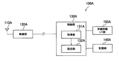
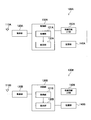
- FIG. 3 is a block diagram showing the configuration of the radio base station according to the first embodiment of the present invention.
- FIG. 4 is a diagram for explaining a tilt angle setting method according to the first embodiment of the present invention (part 1).
- FIG. 5 is a diagram for explaining a tilt angle setting method according to the first embodiment of the present invention (part 2).
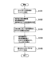
- FIG. 6 is a flowchart showing the operation of the control unit (antenna control apparatus) of the radio base station according to the first embodiment of the present invention.
- FIG. 1 is a schematic configuration diagram of a radio communication system according to the first embodiment of the present invention.
- FIG. 2 is a diagram showing an overview of the antenna control method according to the first embodiment of the present invention.
- FIG. 3 is a block diagram showing the configuration of the radio base station according
- FIG. 7 is a block diagram showing a configuration of a radio base station according to a modification of the first embodiment of the present invention.
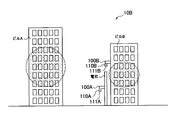
- FIG. 8 is a schematic configuration diagram of a radio communication system according to the second embodiment of the present invention.
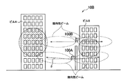
- FIG. 9 is a diagram showing an overview of an antenna control method according to the second embodiment of the present invention.
- FIG. 10 is a block diagram showing a configuration of a radio base station according to the second embodiment of the present invention.
- FIG. 11 is a block diagram showing a configuration of a radio base station according to a modification of the second embodiment of the present invention.
- FIG. 12 is a schematic configuration diagram of a radio communication system according to the third embodiment of the present invention.
- FIG. 13 is a block diagram showing a configuration of a base station control apparatus (antenna control apparatus) according to the third embodiment of the present invention.
- FIG. 1 is a schematic configuration diagram of a radio communication system 10A according to the first embodiment.
- the wireless communication system 10A has a configuration based on a next-generation wireless communication system such as WiMAX or LTE.
- the radio communication system 10A includes a plurality of radio terminals 200 and a radio base station 100A.
- the wireless terminals 200 are scattered in the buildings A and B, and the wireless base station 100A is the connection destination. That is, the wireless terminal 200 performs standby or data transmission / reception with the wireless base station 100A.
- Each wireless terminal 200 includes a position measurement unit such as GPS (Global Positioning System), and measures the position (longitude, latitude, altitude) of the terminal using the position measurement unit.
- Each wireless terminal 200 periodically transmits positioning data indicating the position measurement result to the wireless base station 100A. Note that the positioning data may be data indicating only the altitude of the wireless terminal 200.
- the wireless communication system 10A in order to make a micro cell, the wireless communication system 10A is also installed at a low altitude such as a utility pole, a building pillar, or a building wall located in a valley of a building.
- the radio base station 100 ⁇ / b> A is installed on a utility pole located between a building A and a building B (valley).
- the radio base station 100A includes a directional antenna 110A and a directional antenna 111A (antenna unit).
- Each of the directional antenna 110 ⁇ / b> A and the directional antenna 111 ⁇ / b> A is an antenna that can change a beam direction, which is a direction in which a directional beam is directed, in a vertical plane.
- directivity includes both directivity of transmission directivity and reception directivity.
- the directional antenna 110A is used for wireless communication with the wireless terminal 200 existing in the building A.
- the directional antenna 111 ⁇ / b> A is used for wireless communication with the wireless terminal 200 existing in the building B.
- the directional antenna 110A and the directional antenna 111A are provided integrally with the radio base station 100A main body.
- the directional antenna 110A and the directional antenna 111A are antennas capable of electrically changing the tilt angle, for example.
- specifications of the directional antenna 110A and the directional antenna 111A standardized standards such as AISG can be used.
- the wireless terminals 200 are distributed in the height direction (vertical direction) with respect to the directional antenna 110A and the directional antenna 111A. That is, many wireless terminals 200 exist at positions higher than the altitudes of the directional antenna 110A and the directional antenna 111A.
- the wireless terminals 200 are densely present at a position higher than the ground surface G, specifically, the middle layer or more of the buildings A and B.
- a portion where the wireless terminals 200 are densely present is referred to as a “terminal dense portion”.
- FIG. 2 is a diagram showing an outline of the antenna control method according to the first embodiment.
- the radio base station 100A sets the tilt angle ⁇ of the directional antenna 110A to an elevation angle (above the horizontal direction) in order to direct the directional beam of the directional antenna 110A toward the terminal crowded part in the building A.
- the tilt angle ⁇ is defined as an angle formed by the beam direction D1 and the horizontal direction D2.
- the radio base station 100A sets the tilt angle ⁇ of the directional antenna 110A using the terminal altitude value indicating the altitude of the radio terminal 200 existing in the building A. In this way, in consideration of the altitude of the radio terminal 200 existing in the building A, the tilt angle ⁇ of the directional antenna 110A is adjusted to the altitude of the radio terminal 200.
- the radio base station 100A sets the tilt angle of the directional antenna 111A on the elevation side as shown in FIG.
- the radio base station 100A sets the tilt angle ⁇ of the directional antenna 111A using the terminal altitude value indicating the altitude of the radio terminal 200 existing in the building B. In this way, considering the altitude of the radio terminal 200 existing in the building B, the tilt angle ⁇ of the directional antenna 111A is adjusted to the altitude of the radio terminal 200.
- FIG. 3 is a block diagram showing a configuration of the radio base station 100A according to the first embodiment. Since the same control method is applied to the directional antenna 110A and the directional antenna 111A, the directional antenna 111A will be omitted in the following first embodiment.
- the radio base station 100A includes a directional antenna 110A, a radio unit 120A, a control unit 130A, a storage unit 140A, and a wired line I / F unit 150A.
- the directional antenna 110A is an antenna that can electrically or mechanically change the tilt angle ⁇ on the elevation side. For example, when the elevation angle side is positive, the directional antenna 110A can change the tilt angle ⁇ within a range from 0 ° (horizontal direction) to + 90 °.
- the wireless unit 120A transmits and receives wireless signals via the directional antenna 110A.
- the radio unit 120A includes a transmission unit having an up converter and a power amplifier, and a reception unit having a down converter and a low noise amplifier.
- the control unit 130A is configured using, for example, a CPU, and controls various functions provided in the radio base station 100A.
- the storage unit 140A is configured using, for example, a memory, and stores various types of information used for control in the control unit 130A.
- the control unit 130A and the storage unit 140A constitute an antenna control device that controls the directional antenna 110A.
- the wired line I / F unit 150A is connected to a higher-level network device (such as a server or a gateway) via a wired line.
- the control unit 130A includes an acquisition unit 131A and a setting unit 132A.
- the acquiring unit 131A acquires a terminal altitude value indicating the altitude of the radio terminal 200 based on the positioning data (GPS data) received via the directional antenna 110A and the radio unit 120A.
- the acquisition unit 131A acquires a terminal altitude value for each of the wireless terminals 200.
- the terminal elevation value acquired by the acquisition unit 131A is accumulated in the storage unit 140A.
- the acquiring unit 131A further acquires a base station altitude value ⁇ (see FIG. 6) indicating the altitude of the directional antenna 110A.
- the base station altitude value ⁇ may be a value indicating the altitude of the radio unit 120A or the control unit 130A.
- the base station elevation value ⁇ is stored in advance in the storage unit 140A, and the acquisition unit 131A acquires the base station elevation value ⁇ from the storage unit 140A.
- the acquisition unit 131A may acquire the base station altitude value ⁇ based on the positioning data from the position measurement unit.
- the acquisition unit 131A further acquires a horizontal distance value indicating a horizontal distance between the directional antenna 110A (or the radio base station 100A) and the radio terminal 200.
- the acquisition unit 131A acquires a horizontal distance value for each of the wireless terminals 200.
- the acquisition unit 131A acquires the horizontal distance value based on the positioning data (longitude / latitude) from the radio terminal 200 and the longitude / latitude of the directional antenna 110A (or the radio base station 100A).
- the acquisition unit 131A may acquire the horizontal distance value using a propagation loss value based on the electric field strength.
- the horizontal direction distance value acquired by the acquisition unit 131A is accumulated in the storage unit 140A.
- the setting unit 132A performs statistical processing on the terminal altitude values stored in the storage unit 140A, and determines the altitude value with the most dense distribution of the radio terminals 200 as “the terminal altitude value ⁇ . ”.
- FIG. 4 shows a cumulative density distribution of terminal elevation values for each wireless terminal 200.
- the setting unit 132A specifies the representative value (average value, median value, or mode value) of the terminal elevation values stored in the storage unit 140A as the terminal elevation value ⁇ .
- the setting unit 132A performs statistical processing on the horizontal direction distance value accumulated in the storage unit 140A, and determines the horizontal direction distance value where the distribution of the wireless terminals 200 is most dense as “the horizontal direction distance value”. It is specified as d ′′.
- the setting unit 132A specifies the representative value (average value, median value, or mode value) of the horizontal direction distance values accumulated in the storage unit 140A as the horizontal direction distance value d.
- FIG. 6 is a flowchart showing the operation of the radio base station 100A according to the first embodiment.
- step S101 the setting unit 132A sets the initial value of the tilt angle ⁇ stored in advance in the storage unit 140A in the directional antenna 110A.
- the radio base station 100A is operated using the initial value.
- step S102 the acquisition unit 131A determines the terminal altitude value for each wireless terminal 200 and the horizontal direction for each wireless terminal 200 based on the positioning data (GPS data) received from each of the wireless terminals 200 existing in the vicinity. Get the distance value.
- the acquired terminal elevation value and horizontal direction distance value are stored in the storage unit 140A.
- the acquisition unit 131A acquires the base station altitude value ⁇ .
- step S103 the setting unit 132A identifies the value having the highest distribution density among the terminal elevation values accumulated in the storage unit 140A as the terminal elevation value ⁇ , and the distribution is performed in the horizontal direction distance value accumulated in the storage unit 140A.
- the value with the highest density is specified as the horizontal distance value d.
- step S104 the setting unit 132A uses the terminal altitude value ⁇ specified in step S103, the horizontal distance value d specified in step S103, and the base station altitude value ⁇ acquired in step S102, according to equation (1).
- the tilt angle ⁇ is calculated.
- step S105 the setting unit 132A sets the tilt angle ⁇ calculated in step S104 to the directional antenna 110A.
- the directional antenna 110A changes the beam direction D1 in the vertical plane according to the set tilt angle ⁇ .
- step S102 to step S105 is repeatedly executed at predetermined time intervals.
- the tilt angle ⁇ is controlled to follow the distribution state of the wireless terminal 200.
- the setting unit 132A of the control unit 130A (antenna control apparatus) according to the first embodiment sets the tilt angle ⁇ using the terminal altitude value indicating the altitude of the wireless terminal 200. For this reason, considering the altitude of the radio terminal 200, the tilt angle ⁇ can be automatically adjusted to the altitude of the radio terminal 200, so that a three-dimensional communication area can be constructed.
- the tilt angle ⁇ can be appropriately set, and the radio terminal 200 has high quality. Communication service.
- the setting unit 132A of the control unit 130A (antenna control apparatus) sets the tilt angle ⁇ according to the distribution state of the terminal elevation values acquired for each of the wireless terminals 200.
- the tilt angle ⁇ can be automatically adjusted to the altitude value with the highest distribution density of the wireless terminals 200. Therefore, it is possible to provide a high-quality communication service to the majority of the radio terminals 200.
- FIG. 7 is a block diagram showing a configuration of a radio base station 100A according to a modification of the first embodiment.
- the directional antenna 110A is provided integrally with the radio base station 100A main body.
- the directional antenna 110A is provided separately from the radio base station 100A main body.
- the radio unit 120A and the control unit 130A of the radio base station 100A are connected via an optical fiber line or the like.
- standardized standards such as CPRI (Common Public Radio Interface) can be used.
- the wireless device (REC) having the directional antenna 110A and the wireless unit 120A is installed on the utility pole, and the wireless control device (REC) having the control unit 130A, the storage unit 140A, and the wired line I / F unit 150A is installed. It is assumed to be installed on the ground.
- the altitude value of the directional antenna 110A or the radio unit 120A is preferable to use as the base station altitude value ⁇ described above.
- FIG. 8 is a schematic configuration diagram of a radio communication system 10B according to the second embodiment.
- the radio communication system 10B is different from the first embodiment in that the radio communication system 10B includes radio base stations 100A and radio base stations 100B installed in a distributed manner in the height direction.
- the radio base station 100B is installed on the wall surface of the building B above the radio base station 100A.
- the radio base station 100B includes a directional antenna 110B and a directional antenna 111B.
- the directional antenna 110 ⁇ / b> B is used for wireless communication with the wireless terminal 200 existing in the building A.
- the directional antenna 111B is used for wireless communication with the wireless terminal 200 existing in the building B.
- the configuration of the radio base station 100A is the same as that in the first embodiment.
- the radio base station 100A and the radio base station 100B have a positional relationship between the radio base station 100A and the radio base station 100B and tilts set by the radio base station 100A and the radio base station 100B, respectively. Based on the value of the angle, the tilt angle is set so that the directional beams do not overlap each other.
- FIG. 10 is a block diagram showing configurations of the radio base station 100A and the radio base station 100B. Since the same control method as that for the directional antenna 110A and the directional antenna 110B is applied to the directional antenna 111A and the directional antenna 111B, in the following second embodiment, the directional antenna 111A and the directional antenna 111B. A description will be given omitting 111B.
- Each of the radio base station 100A and the radio base station 100B is configured in the same manner as in the first embodiment. However, it differs from the first embodiment in that the wired line I / F unit 150A of the radio base station 100A and the wired line I / F unit 150B of the radio base station 100B are connected to each other via a wired line. ing.
- a wired line a standardized interface such as an X2 interface in LTE can be used.
- the acquisition unit 131A of the radio base station 100A receives the tilt angle information indicating the tilt angle of the directional antenna 110B having a different installation position from the directional antenna 110A, and the installation position information indicating the installation position of the directional antenna 110B. Obtained from the radio base station 100B via the I / F unit 150A.
- the setting unit 132A of the radio base station 100A sets the tilt angle ⁇ of the directional antenna 110A using the tilt angle information and the installation position information acquired by the acquisition unit 131A. Specifically, the setting unit 132A mutually determines the position of the wireless base station 100A and the wireless base station 100B and the tilt angle values set by the wireless base station 100A and the wireless base station 100B.
- the tilt angle ⁇ is set so that the two directional beams do not overlap.
- the acquisition unit 131A may acquire the terminal altitude value ⁇ used for setting the tilt angle of the directional antenna 110B in the radio base station 100B from the radio base station 100B.
- the setting unit 132A makes the terminal altitude value ⁇ used for setting the tilt angle ⁇ of the directional antenna 110A of the own station different from the terminal altitude value ⁇ in the radio base station 100B. For example, when the directional beam of the directional antenna 110B is directed to the altitude value with the highest distribution density of the radio terminal 200, the setting unit 132A sets the altitude value with the second highest distribution density of the radio terminal 200.
- the tilt angle ⁇ is set so that the directional beam of the directional antenna 110A is directed.
- FIG. 11 is a block diagram showing a configuration of a radio base station 100A according to a modification of the second embodiment.
- This modified example is a form in which the modified example of the first embodiment described above and the second embodiment are used in combination.
- the radio base station 100A and the radio base station 100B are distributed and installed in the height direction.
- the directional antenna 110A and the directivity of the same radio base station 100A are used.
- the antenna 110B can be dispersed and installed in the height direction.
- the directional antenna 110A shown in FIG. 11 is installed on the utility pole as in FIGS. 8 and 9, and the directional antenna 110B shown in FIG. 11 is installed on the wall surface of the building B as in FIGS.
- the setting unit 132A of the radio base station 100A sets the tilt angles of the directional antenna 110A and the directional antenna 110B so that the directional beams of the directional antenna 110A and the directional antenna 110B do not overlap.
- the tilt angle is set in a higher-level network device.
- first embodiment and the second embodiment only differences from the first embodiment and the second embodiment will be described, and overlapping descriptions will be omitted.
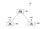
- FIG. 12 is a schematic configuration diagram of a wireless communication system 10C according to the third embodiment.
- each of the radio base station 100A and the radio base station 100B is configured in the same manner as in the second embodiment.
- the radio communication system 10C is different from the second embodiment in that the radio communication system 10C includes a base station control device 300 that controls the radio base station 100A and the radio base station 100B.
- the base station controller 300 is connected to the radio base station 100A and the radio base station 100B via a wired line (backhaul network).
- EMS lement Management System
- the base station control device 300 constitutes an antenna control device that controls the directional antenna 110A of the radio base station 100A.
- the base station control apparatus 300 also controls the directional antenna 110B of the radio base station 100B.
- FIG. 13 is a block diagram showing a configuration of the base station control device 300.
- the base station control apparatus 300 includes a control unit 330, a storage unit 340, and a wired line I / F unit 350.
- the control unit 330 includes an acquisition unit 331 and a setting unit 332.
- the acquisition unit 331 has the same function as the acquisition unit 131A described in the first embodiment and the second embodiment.
- the setting unit 332 has the same function as the setting unit 132A described in the first embodiment and the second embodiment.
- the wireless terminal 200 measures the position (longitude, latitude, altitude) of its own terminal and transmits positioning data to the base station side, but other methods may be used.
- the radio terminal 200 may be configured to transfer the demodulated GPS signal to the base station side and to return position information (positioning data) calculated on the base station side. That is, the calculation subject of the position information (positioning data) is not limited to the wireless terminal 200.
- the antenna 110A and the antenna 111A have directivity with respect to different buildings.
- the antenna 110A and the antenna 111A are MIMO (Multiple Input Input Multiple Output), that is, multiple antennas. It may be used for transmission.
- MIMO Multiple Input Input Multiple Output
- LTE Long Term Evolution
- a MIMO scheme is adopted, and the same area can be covered with a plurality of antennas, and data can be multiplexed.
- both the antenna 110A and the antenna 111A have an omni antenna, that is, a circular directivity pattern centered on the antenna in a horizontal plane. And when it cuts out by a vertical surface, it will have the pattern represented by the two ellipses drawn with the broken line in FIG.
- the number of antennas constituting the antenna unit is not limited as long as the beam direction can be changed in the vertical plane.
- the setting unit 132A or the setting unit 332 may set the beam width of the directional beam according to the distribution state of the terminal altitude values in addition to setting the tilt angle ⁇ . Specifically, the setting unit 132A or the setting unit 332 widens the beam width from the initial value when the wireless terminal 200 is dispersed over a predetermined range in the height direction. Further, the setting unit 132A or the setting unit 332 makes the beam width narrower than the initial value when the radio terminal 200 is concentrated below a predetermined range in the height direction. By such control, it is possible to provide a higher quality communication service to the wireless terminal 200.
- the tilt angle ⁇ may be set.
- the setting unit 132A or the setting unit 332 increases the tilt angle ⁇ on the elevation side as the difference between the terminal altitude value ⁇ and the base station altitude value ⁇ increases. Set larger in.
- the setting unit 132A or the setting unit 332 sets the tilt angle ⁇ as the difference between the terminal elevation value ⁇ and the base station elevation value ⁇ is smaller. Set smaller on the elevation side. According to such a setting method, although the accuracy of setting the tilt angle ⁇ is lowered, the horizontal distance value d can be eliminated, and the processing load can be reduced.
- the horizontal distance value d may be used for weighting the radio terminal 200.
- the communication quality of the radio terminal 200 is improved by setting the tilt angle ⁇ so that the directional beam is preferentially directed toward the radio terminal 200 having a large horizontal distance value d (a long distance). Can be considered.
- the antenna control apparatus (the control unit 130A or the base station control apparatus 300) sets the tilt angle ⁇ according to the distribution state of the terminal altitude values has been described.
- the process of step S103 of FIG. 4 may be omitted.
- the acquisition of the radio base station 100A may acquire the terminal altitude value, the base station altitude value, and the horizontal direction distance value from the network device via the wired line I / F unit 150A.
- the antenna unit that can electrically change the tilt angle has been described.
- an antenna unit that can mechanically change the tilt angle may be used.
- the antenna control device, the wireless communication system, and the antenna control method according to the present invention can be used even when the base station antenna is installed at a low altitude and the wireless terminals are distributed in the height direction. Since the tilt angle can be set appropriately and a high-quality communication service can be provided to the wireless terminal, it is useful in wireless communication such as mobile communication.
Landscapes
- Engineering & Computer Science (AREA)
- Computer Networks & Wireless Communication (AREA)
- Signal Processing (AREA)
- Mobile Radio Communication Systems (AREA)
- Radio Transmission System (AREA)
Abstract
Description
第1実施形態においては、(1)無線通信システムの概要、(2)無線基地局の構成、(3)無線基地局の動作、(4)作用効果について説明する。
図1は、第1実施形態に係る無線通信システム10Aの概略構成図である。無線通信システム10Aは、WiMAXやLTEといった次世代無線通信システムに基づく構成を有している。
図3は、第1実施形態に係る無線基地局100Aの構成を示すブロック図である。なお、指向性アンテナ110A及び指向性アンテナ111Aには同様の制御方法が適用されるため、以下の第1実施形態では、指向性アンテナ111Aを省略して説明する。
θ=tan-1{(α-β)/d} ・・・(1)
の数式に従って、チルト角θを設定する。
図6は、第1実施形態に係る無線基地局100Aの動作を示すフローチャートである。
第1実施形態に係る制御部130A(アンテナ制御装置)の設定部132Aは、無線端末200の標高を示す端末標高値を用いてチルト角θを設定する。このため、無線端末200の標高を考慮し、チルト角θを自動で無線端末200の標高に合わせることができるため、3次元的な通信エリアを構築可能となる。
図7は、第1実施形態の変更例に係る無線基地局100Aの構成を示すブロック図である。
第2実施形態においては、(1)無線通信システムの概要、(2)無線基地局の構成、(3)作用効果について説明する。ただし、第1実施形態と異なる点についてのみ説明し、重複する説明は省略する。
図8は、第2実施形態に係る無線通信システム10Bの概略構成図である。図8に示すように、無線通信システム10Bは、高さ方向に分散して設置された無線基地局100A及び無線基地局100Bを有する点で第1実施形態とは異なる。図8の例では、無線基地局100Bは、無線基地局100Aよりも上方において、ビルBの壁面に設置されている。
図10は、無線基地局100A及び無線基地局100Bの構成を示すブロック図である。なお、指向性アンテナ111A及び指向性アンテナ111Bには、指向性アンテナ110A及び指向性アンテナ110Bと同様の制御方法が適用されるため、以下の第2実施形態では、指向性アンテナ111A及び指向性アンテナ111Bを省略して説明する。
第2実施形態によれば、無線基地局100A及び無線基地局100Bが高さ方向に分布する場合でも、無線基地局100A及び無線基地局100Bそれぞれの指向性ビームが重ならないようにチルト角を設定することで、互いの干渉を回避することができ、無線端末200に対してさらに高品質の通信サービスを提供できる。
図11は、第2実施形態の変更例に係る無線基地局100Aの構成を示すブロック図である。本変更例は、上述した第1実施形態の変更例と第2実施形態とを併用した形態である。
第3実施形態においては、チルト角の設定を上位のネットワーク装置において行う形態である。以下の第3実施形態においては、第1実施形態及び第2実施形態と異なる点についてのみ説明し、重複する説明は省略する。
上記のように、本発明は実施形態(第1実施形態~第3実施形態)によって記載したが、この開示の一部をなす論述及び図面はこの発明を限定するものであると理解すべきではない。この開示から当業者には様々な代替実施形態、実施例及び運用技術が明らかとなる。
Claims (12)
- 指向性ビームが向けられる方向であるビーム方向を垂直面内で変更可能なアンテナ部を制御するアンテナ制御装置であって、
前記アンテナ部を有する無線基地局を接続先とする無線端末の標高を示す端末標高値を取得する取得部と、
前記取得部によって取得された前記端末標高値を用いて、前記ビーム方向と水平方向との成す角度であるチルト角を設定する設定部と
を備えるアンテナ制御装置。 - 前記設定部は、前記チルト角を仰角側に設定する請求項1に記載のアンテナ制御装置。
- 前記無線基地局が高さ方向に分布する複数の無線端末の接続先である場合に、前記取得部は、前記複数の無線端末のそれぞれについて前記端末標高値を取得し、
前記設定部は、前記複数の無線端末のそれぞれについて取得された前記端末標高値の分布状態に応じて、前記チルト角を設定する請求項1に記載のアンテナ制御装置。 - 前記設定部は、前記チルト角を設定することに加え、前記分布状態に応じて前記指向性ビームのビーム幅を設定する請求項3に記載のアンテナ制御装置。
- 前記取得部は、
前記アンテナ部又は前記無線基地局の標高を示す基地局標高値をさらに取得し、
前記設定部は、前記取得部によって取得された前記基地局標高値をさらに用いて、前記チルト角を設定する請求項1に記載のアンテナ制御装置。 - 前記端末標高値が前記基地局標高値よりも高い場合、前記設定部は、前記端末標高値と前記基地局標高値との間の差が大きいほど、前記チルト角を仰角側において大きく設定する請求項5に記載のアンテナ制御装置。
- 前記取得部は、前記アンテナ部と設置位置が異なる他のアンテナ部に関する情報をさらに取得し、
前記設定部は、前記他のアンテナ部に関する情報をさらに用いて、前記アンテナ部の指向性ビームと前記他のアンテナ部の指向性ビームとが重ならないように前記チルト角を設定する請求項1に記載のアンテナ制御装置。 - 前記取得部は、前記アンテナ部又は前記無線基地局と、前記無線端末との間の水平方向における距離を示す水平方向距離値をさらに取得し、
前記設定部は、前記取得部によって取得された前記水平方向距離値をさらに用いて、前記チルト角を設定する請求項1に記載のアンテナ制御装置。 - 前記無線端末における位置測定結果を示す測位データを前記無線端末から前記無線基地局が受信した場合、前記取得部は、前記無線基地局が受信した前記測位データに基づいて前記端末標高値を取得する請求項1に記載のアンテナ制御装置。
- 第1のアンテナ部を有する第1の無線基地局と、第2のアンテナ部を有する第2の無線基地局とを具備し、LTEに対応した無線通信システムであって、
前記第1の無線基地局は、前記第1のアンテナ部のチルト角を示すチルト角情報をX2インタフェースを介して前記第2の無線基地局に送信する送信部を備え、
前記第2の無線基地局は、前記チルト角情報を前記X2インタフェースを介して受信する受信部を備える無線通信システム。 - 第1のアンテナ部を有する第1の無線基地局と、第2のアンテナ部を有する第2の無線基地局とを具備し、LTEに対応した無線通信システムであって、
前記第1の無線基地局は、前記第1のアンテナ部の設置位置を示す設置位置情報をX2インタフェースを介して前記第2の無線基地局に送信する送信部を備え、
前記第2の無線基地局は、前記設置位置情報を前記X2インタフェースを介して受信する受信部を備える無線通信システム。 - 指向性ビームが向けられる方向であるビーム方向を垂直面内で変更可能なアンテナ部を制御するアンテナ制御方法であって、
前記指向性アンテナを有する無線基地局を接続先とする無線端末の標高を示す端末標高値を取得するステップと、
前記取得するステップにおいて取得された前記端末標高値を用いて、前記ビーム方向と水平方向との成す角度であるチルト角を設定するステップと
を含むアンテナ制御方法。
Priority Applications (2)
| Application Number | Priority Date | Filing Date | Title |
|---|---|---|---|
| US13/260,148 US20120015684A1 (en) | 2009-03-26 | 2010-03-25 | Antenna controller device, radio communication system, and antenna controlling method |
| JP2011506128A JPWO2010110396A1 (ja) | 2009-03-26 | 2010-03-25 | アンテナ制御装置、無線通信システム及びアンテナ制御方法 |
Applications Claiming Priority (2)
| Application Number | Priority Date | Filing Date | Title |
|---|---|---|---|
| JP2009077747 | 2009-03-26 | ||
| JP2009-077747 | 2009-03-26 |
Publications (1)
| Publication Number | Publication Date |
|---|---|
| WO2010110396A1 true WO2010110396A1 (ja) | 2010-09-30 |
Family
ID=42781086
Family Applications (1)
| Application Number | Title | Priority Date | Filing Date |
|---|---|---|---|
| PCT/JP2010/055286 Ceased WO2010110396A1 (ja) | 2009-03-26 | 2010-03-25 | アンテナ制御装置、無線通信システム及びアンテナ制御方法 |
Country Status (3)
| Country | Link |
|---|---|
| US (1) | US20120015684A1 (ja) |
| JP (1) | JPWO2010110396A1 (ja) |
| WO (1) | WO2010110396A1 (ja) |
Cited By (2)
| Publication number | Priority date | Publication date | Assignee | Title |
|---|---|---|---|---|
| JP2015050481A (ja) * | 2013-08-29 | 2015-03-16 | Kddi株式会社 | 判定装置並びに判定方法、基地局装置、及びプログラム |
| JP2019102837A (ja) * | 2017-11-28 | 2019-06-24 | 株式会社Hysエンジニアリングサービス | 映像受信システムおよび映像受信方法 |
Families Citing this family (15)
| Publication number | Priority date | Publication date | Assignee | Title |
|---|---|---|---|---|
| JP6053305B2 (ja) * | 2012-03-30 | 2016-12-27 | 株式会社Nttドコモ | 無線基地局、無線通信システム及び無線通信方法 |
| US9788194B1 (en) * | 2013-03-14 | 2017-10-10 | Sprint Spectrum L.P. | Dynamically adjusting base station configuration based on altitude |
| WO2015004895A1 (ja) * | 2013-07-10 | 2015-01-15 | 日本電気株式会社 | 無線通信システム、基地局および制御方法 |
| CN105393470B (zh) * | 2013-08-08 | 2018-11-02 | 英特尔Ip公司 | 用于多输入多输出系统中的电子下倾角调节的方法、装置和系统 |
| US9590298B1 (en) * | 2015-05-13 | 2017-03-07 | Amazon Technologies, Inc. | Orientation of directional antennas |
| CN106297229B (zh) | 2015-06-25 | 2019-08-02 | 北京智谷睿拓技术服务有限公司 | 交互方法及通信设备 |
| CN107025780B (zh) * | 2015-06-25 | 2020-09-01 | 北京智谷睿拓技术服务有限公司 | 交互方法及通信设备 |
| CN106297230B (zh) | 2015-06-25 | 2019-07-26 | 北京智谷睿拓技术服务有限公司 | 交互方法及通信设备 |
| US10462754B1 (en) * | 2017-04-03 | 2019-10-29 | Sprint Spectrum L.P. | Systems and methods for selectively reducing an allowable transmit power of a wireless device |
| BR112020006516A2 (pt) | 2017-10-23 | 2020-09-29 | Ipcom Gmbh & Co. Kg | redução de interferências causadas por veículos aéreos |
| US11510117B2 (en) | 2018-03-27 | 2022-11-22 | Telefonaktiebolaget Lm Ericsson (Publ) | Method for handling of connections of wireless devices to base stations based on altitude indications |
| KR102583202B1 (ko) * | 2019-02-12 | 2023-09-25 | 지오 플랫폼즈 리미티드 | Nb-iot 네트워크에서 센서 데이터 유형 식별을 위한 방법 및 시스템 |
| US12120532B2 (en) * | 2019-10-18 | 2024-10-15 | Nippon Telegraph And Telephone Corporation | Station placement designing method and station placement designing apparatus |
| CN111479291B (zh) * | 2020-04-13 | 2022-08-16 | 杭州零域信息技术有限公司 | Wi-Fi信号相对高度智能测量方法 |
| CN114726408A (zh) * | 2021-01-04 | 2022-07-08 | 中国移动通信有限公司研究院 | 波束赋形方法、装置、基站及存储介质 |
Citations (4)
| Publication number | Priority date | Publication date | Assignee | Title |
|---|---|---|---|---|
| JPH07283642A (ja) * | 1994-04-05 | 1995-10-27 | Fujita Corp | 固定局と移動体のアンテナ指向方向調整方法及びその装置 |
| JPH11191752A (ja) * | 1997-12-25 | 1999-07-13 | Hitachi Ltd | 無線基地局、無線通信エリア形成方法 |
| JP2000059291A (ja) * | 1998-07-06 | 2000-02-25 | Soc Francaise Du Radiotelephone | 基地局と移動無線電話との間の通信用の1つ又は複数の放射電波ビ―ムを方向づける処理プロセス、及びそれに対応する基地局 |
| JP2003249819A (ja) * | 2002-02-22 | 2003-09-05 | Japan Radio Co Ltd | 基地局アンテナ |
Family Cites Families (6)
| Publication number | Priority date | Publication date | Assignee | Title |
|---|---|---|---|---|
| KR100447411B1 (ko) * | 2001-12-26 | 2004-09-04 | 한국전자통신연구원 | 이동 단말기의 위치 추적 장치 및 방법 |
| US6785559B1 (en) * | 2002-06-28 | 2004-08-31 | Interdigital Technology Corporation | System for efficiently covering a sectorized cell utilizing beam forming and sweeping |
| CA2393552C (en) * | 2002-07-31 | 2004-11-30 | Yuan Xie | A three-dimensional space coverage cellular network |
| GB2414634B (en) * | 2003-08-04 | 2008-10-01 | Nec Corp | Method for deciding tilt angle of antenna in radio communication system and apparatus for deciding the same |
| GB0616449D0 (en) * | 2006-08-18 | 2006-09-27 | Quintel Technology Ltd | Diversity antenna system with electrical tilt |
| CN101689897B (zh) * | 2007-06-20 | 2013-02-27 | 艾利森电话股份有限公司 | 用于在移动无线网络中使用宏分集来进行干扰抑制的系统和设备 |
-
2010
- 2010-03-25 JP JP2011506128A patent/JPWO2010110396A1/ja active Pending
- 2010-03-25 US US13/260,148 patent/US20120015684A1/en not_active Abandoned
- 2010-03-25 WO PCT/JP2010/055286 patent/WO2010110396A1/ja not_active Ceased
Patent Citations (4)
| Publication number | Priority date | Publication date | Assignee | Title |
|---|---|---|---|---|
| JPH07283642A (ja) * | 1994-04-05 | 1995-10-27 | Fujita Corp | 固定局と移動体のアンテナ指向方向調整方法及びその装置 |
| JPH11191752A (ja) * | 1997-12-25 | 1999-07-13 | Hitachi Ltd | 無線基地局、無線通信エリア形成方法 |
| JP2000059291A (ja) * | 1998-07-06 | 2000-02-25 | Soc Francaise Du Radiotelephone | 基地局と移動無線電話との間の通信用の1つ又は複数の放射電波ビ―ムを方向づける処理プロセス、及びそれに対応する基地局 |
| JP2003249819A (ja) * | 2002-02-22 | 2003-09-05 | Japan Radio Co Ltd | 基地局アンテナ |
Cited By (2)
| Publication number | Priority date | Publication date | Assignee | Title |
|---|---|---|---|---|
| JP2015050481A (ja) * | 2013-08-29 | 2015-03-16 | Kddi株式会社 | 判定装置並びに判定方法、基地局装置、及びプログラム |
| JP2019102837A (ja) * | 2017-11-28 | 2019-06-24 | 株式会社Hysエンジニアリングサービス | 映像受信システムおよび映像受信方法 |
Also Published As
| Publication number | Publication date |
|---|---|
| US20120015684A1 (en) | 2012-01-19 |
| JPWO2010110396A1 (ja) | 2012-10-04 |
Similar Documents
| Publication | Publication Date | Title |
|---|---|---|
| WO2010110396A1 (ja) | アンテナ制御装置、無線通信システム及びアンテナ制御方法 | |
| EP3375216B1 (en) | Dynamic positioning method for mobile cells | |
| EP2169977B1 (en) | Base station device in mobile communication system, and directivity controlling method | |
| EP2425648B1 (en) | Self-optimizing wireless network base station | |
| US10547372B2 (en) | System, device, and method for high-frequency millimeter-wave wireless communication using interface points | |
| US9831543B2 (en) | Adaptable antenna apparatus for base station | |
| JP6355110B2 (ja) | 分散アンテナアレイシステムによる通信方法、アレイシステムおよびコントローラ | |
| US20070218910A1 (en) | Dynamic beam steering of backhaul traffic | |
| US20120264450A1 (en) | Method and Arrangement in a Telecommunication System | |
| CN108464030A (zh) | 用于与波束形成天线通信的方法和系统 | |
| JPWO2011024310A1 (ja) | 移動体通信システム、移動局装置、基地局装置及び電波干渉低減方法 | |
| CN114175516B (zh) | 无线通信系统中的电子设备和方法 | |
| WO2023134526A1 (zh) | 电子设备、无线通信方法和计算机可读存储介质 | |
| KR102631820B1 (ko) | Tvws 지향성 안테나를 이용한 원거리 통신 시스템 제어 방법 | |
| EP1525767B1 (en) | Telecommunications radio system for mobile communication services | |
| CN103179587A (zh) | 基站 | |
| JP2021190892A (ja) | 制御装置、制御方法、プログラム | |
| CN114600514A (zh) | 控制无线电设备的传输功率 | |
| JP2012222496A (ja) | 基地局 | |
| KR101067367B1 (ko) | 빔 스캐닝 기법을 이용한 무선 네트워크 접속 장치 및 방법 | |
| CN116567643A (zh) | 动态资源共享 | |
| EP3777342B1 (en) | Network access nodes and client device for reporting of mobility information of a network access node | |
| JP2012161031A (ja) | 基地局及び基地局の自律設定方法 | |
| JP2011146794A (ja) | 無線通信基地局装置及び無線通信方法 | |
| JP2012175540A (ja) | 基地局及び基地局の自律設定方法 |
Legal Events
| Date | Code | Title | Description |
|---|---|---|---|
| 121 | Ep: the epo has been informed by wipo that ep was designated in this application |
Ref document number: 10756192 Country of ref document: EP Kind code of ref document: A1 |
|
| WWE | Wipo information: entry into national phase |
Ref document number: 2011506128 Country of ref document: JP |
|
| WWE | Wipo information: entry into national phase |
Ref document number: 13260148 Country of ref document: US |
|
| NENP | Non-entry into the national phase |
Ref country code: DE |
|
| 122 | Ep: pct application non-entry in european phase |
Ref document number: 10756192 Country of ref document: EP Kind code of ref document: A1 |