WO2010104313A2 - Method for controlling transmission power in a multi-antenna wireless communication system - Google Patents
Method for controlling transmission power in a multi-antenna wireless communication system Download PDFInfo
- Publication number
- WO2010104313A2 WO2010104313A2 PCT/KR2010/001459 KR2010001459W WO2010104313A2 WO 2010104313 A2 WO2010104313 A2 WO 2010104313A2 KR 2010001459 W KR2010001459 W KR 2010001459W WO 2010104313 A2 WO2010104313 A2 WO 2010104313A2
- Authority
- WO
- WIPO (PCT)
- Prior art keywords
- transmission
- transmission power
- rank
- power
- determined
- Prior art date
Links
Images


Classifications
-
- H—ELECTRICITY
- H04—ELECTRIC COMMUNICATION TECHNIQUE
- H04W—WIRELESS COMMUNICATION NETWORKS
- H04W52/00—Power management, e.g. TPC [Transmission Power Control], power saving or power classes
- H04W52/04—TPC
- H04W52/06—TPC algorithms
- H04W52/14—Separate analysis of uplink or downlink
- H04W52/146—Uplink power control
-
- H—ELECTRICITY
- H04—ELECTRIC COMMUNICATION TECHNIQUE
- H04B—TRANSMISSION
- H04B7/00—Radio transmission systems, i.e. using radiation field
- H04B7/02—Diversity systems; Multi-antenna system, i.e. transmission or reception using multiple antennas
- H04B7/04—Diversity systems; Multi-antenna system, i.e. transmission or reception using multiple antennas using two or more spaced independent antennas
- H04B7/06—Diversity systems; Multi-antenna system, i.e. transmission or reception using multiple antennas using two or more spaced independent antennas at the transmitting station
- H04B7/0613—Diversity systems; Multi-antenna system, i.e. transmission or reception using multiple antennas using two or more spaced independent antennas at the transmitting station using simultaneous transmission
- H04B7/0615—Diversity systems; Multi-antenna system, i.e. transmission or reception using multiple antennas using two or more spaced independent antennas at the transmitting station using simultaneous transmission of weighted versions of same signal
- H04B7/0619—Diversity systems; Multi-antenna system, i.e. transmission or reception using multiple antennas using two or more spaced independent antennas at the transmitting station using simultaneous transmission of weighted versions of same signal using feedback from receiving side
- H04B7/0621—Feedback content
- H04B7/063—Parameters other than those covered in groups H04B7/0623 - H04B7/0634, e.g. channel matrix rank or transmit mode selection
-
- H—ELECTRICITY
- H04—ELECTRIC COMMUNICATION TECHNIQUE
- H04W—WIRELESS COMMUNICATION NETWORKS
- H04W52/00—Power management, e.g. TPC [Transmission Power Control], power saving or power classes
- H04W52/04—TPC
- H04W52/18—TPC being performed according to specific parameters
- H04W52/24—TPC being performed according to specific parameters using SIR [Signal to Interference Ratio] or other wireless path parameters
-
- Y—GENERAL TAGGING OF NEW TECHNOLOGICAL DEVELOPMENTS; GENERAL TAGGING OF CROSS-SECTIONAL TECHNOLOGIES SPANNING OVER SEVERAL SECTIONS OF THE IPC; TECHNICAL SUBJECTS COVERED BY FORMER USPC CROSS-REFERENCE ART COLLECTIONS [XRACs] AND DIGESTS
- Y02—TECHNOLOGIES OR APPLICATIONS FOR MITIGATION OR ADAPTATION AGAINST CLIMATE CHANGE
- Y02D—CLIMATE CHANGE MITIGATION TECHNOLOGIES IN INFORMATION AND COMMUNICATION TECHNOLOGIES [ICT], I.E. INFORMATION AND COMMUNICATION TECHNOLOGIES AIMING AT THE REDUCTION OF THEIR OWN ENERGY USE
- Y02D30/00—Reducing energy consumption in communication networks
- Y02D30/70—Reducing energy consumption in communication networks in wireless communication networks
Definitions
- the present invention relates to a wireless access system, and more particularly, to a method for controlling uplink transmission power in consideration of a transmission rank in a multi-antenna environment, and an apparatus for performing the same.
- MIMO Multi-Input Multi-Output
- MIMO is a method using a plurality of transmission antennas and a plurality of reception antennas, and this method can improve the transmission and reception efficiency of data. That is, by using a plurality of antennas at the transmitting end or the receiving end of the wireless communication system, the capacity can be increased and the performance can be improved.
- MIMO may be referred to as a 'multi-antenna'.
- a multi-antenna technique In a multi-antenna technique, it does not rely on a single antenna path to receive one full message. Instead, the multi-antenna technique completes data by merging each data fragment received from multiple antennas. Using multi-antenna technology, it is possible to improve the data rate within a cell area of a specified size or to increase system coverage while guaranteeing a specific data rate. This technique can also be widely used in mobile communication terminals, repeaters, and the like. According to the multiple antenna technology, it is possible to overcome the transmission limit in the mobile communication according to the prior art, which used a single antenna.
- FIG. 1 A schematic diagram of a typical multiple antenna (MIMO) communication system is shown in FIG.
- the transmitting end is provided with N T antennas
- the receiving end is provided with N R antennas.
- the theoretical channel transmission capacity is increased than when the plurality of antennas are used in only one of the transmitting end and the receiving end.
- the increase in channel transmission capacity is proportional to the number of antennas. Therefore, the transmission rate is improved and the frequency efficiency is improved. If the maximum transmission rate when using one antenna is R o , the transmission rate when using multiple antennas can theoretically be increased by multiplying the rate of increase R i by the above R o .
- the multi-antenna technique includes a spatial diversity scheme that improves transmission reliability by using symbols that pass through various channel paths, and a spatial multiplexing technique that improves a transmission rate by simultaneously transmitting a plurality of data symbols by using a plurality of transmit antennas. (spatial multiplexing). You can also combine these two approaches properly to get the benefits of each.
- the present invention has been made to solve the problems of the general technology as described above, and an object of the present invention is to provide a method for efficiently controlling uplink transmission power in a multi-antenna environment and an apparatus for performing the same.
- Another object of the present invention is to provide a method for controlling an efficient uplink transmission power in consideration of an uplink transmission rank in a multi-antenna environment, and an apparatus for performing the same.
- a method of performing transmission power control of an uplink data channel in a transmitter supporting a plurality of transmission ranks may be performed in a transmission rank in a specific subframe. Determining a first transmit power using at least one rank variable that is dependent; Comparing a second transmission power that is a preset maximum transmission power with the determined first transmission power; And determining a smaller value as a result of the comparison as the transmission power of the data channel.
- the determining of the first transmission power may be performed using at least one of a transmission path loss compensation variable, a bandwidth of the data channel, a closed loop power correction variable, and a reference power determined by an upper layer.
- the rank variable may be an offset value for power correction set for each rank.
- the offset value may be determined through higher layer signaling or a control channel.
- the rank variable may be a parameter for power compensation through a modulation and coding scheme (MCS) for dynamic channel change.
- MCS modulation and coding scheme
- the parameter may be determined using a value obtained by dividing the size of data transmitted in the subframe by the number of resource elements.
- the size of the transmitted data is preferably the sum of the block size of each data unit transmitted in the subframe.
- the data unit block is preferably a transport block or a code block.
- a mobile terminal supporting a plurality of transmission ranks includes a processor; And a radio communication (RF) module for transmitting and receiving a radio signal to and from the outside under the control of the processor.
- the processor determines the first transmission power using at least one rank variable that depends on the transmission rank in a specific subframe, and compares the determined first transmission power with a second transmission power that is a preset maximum transmission power. The lower value is determined as the transmission power of the data channel, and the wireless communication module can be controlled to transmit the data channel with the determined transmission power.
- the processor may further determine the first transmission power using at least one of a transmission path loss compensation variable, a bandwidth of the data channel, a closed loop power correction variable, and a reference power determined by an upper layer.
- the rank variable may be an offset value for power correction set for each transmission rank.
- the offset value is preferably determined through higher layer signaling or a control channel.
- the rank variable is preferably a parameter for power compensation through a modulation and coding scheme (MCS) for dynamic channel change.
- MCS modulation and coding scheme
- the parameter is preferably determined using a value obtained by dividing the size of data transmitted in the subframe by the number of resource elements.
- the size of the transmitted data is preferably the sum of the block size of each data unit transmitted in the subframe.
- the data unit block is preferably a transport block or a code block.
- the transmission of the data channel is preferably performed by spatial multiplexing.
- the reference power determined by the upper layer may be determined by the sum of a UE specific value and a cell-specific value.
- the uplink data channel is preferably a physical uplink shared channel (PUSCH).
- uplink transmission power can be efficiently controlled in a multi-antenna environment through embodiments of the present invention.
- the rank is considered in determining uplink transmission power in a multi-antenna environment, thereby enabling more efficient control of transmission power.
- MIMO general multiple antenna
- 3 and 4 are diagrams for explaining a relationship between an antenna, a stream, and a codeword in a MIMO communication system.
- FIG. 5 is a diagram for describing physical channels used in a 3rd generation partnership project (3GPP) long term evolution (LTE) system, which is an example of a mobile communication system, and a general signal transmission method using the same.
- 3GPP 3rd generation partnership project
- LTE long term evolution
- FIG. 6 is a block diagram illustrating an example of a structure of a transmitting end and a receiving end according to another embodiment of the present invention.
- a terminal collectively refers to a mobile or fixed user terminal device such as a user equipment (UE), a mobile station (MS), and the like.
- the base station collectively refers to any node of the network side that communicates with the terminal, such as Node B, eNode B, Base Station.
- Peak power to average power ratio is a parameter that indicates the characteristics of the waveform. This value is a value obtained by dividing the peak amplitude of the waveform by the time-averaged root mean square (RMS) value of the waveform and having no dimensionless dimension.
- RMS root mean square
- the PAPR of a single carrier signal is better than the PAPR of a multi carrier signal.
- multiple input multiple output can be implemented using single carrier-frequency division multiple access (SC-FDMA) to maintain good cubic metric (CM) properties.
- SC-FDMA single carrier-frequency division multiple access
- CM cubic metric
- PAPR is related to the dynamic range that a power amplifier must support on the transmitter side
- cubic metric value is another value that can represent the value represented by the PAPR.
- Equation 1 Equation 1
- each transmission information Different transmit powers, and each transmit power In this case, transmission information whose transmission power is adjusted May be represented by a vector such as Equation 3.
- N T transmitted signals are actually transmitted.
- the weight matrix W may be applied to the configuration.
- the weight matrix plays a role of properly distributing transmission information to each antenna according to a transmission channel situation.
- Such a transmission signal May be expressed as a vector x , and x may be represented as in Equation 5.
- the signal vector x is expressed as follows.
- w ij is the j th information transmitted through the i th transmit antenna
- W is referred to as a weight matrix or a precoding matrix.
- the above-described transmission signal x can be considered divided into the case of using the spatial diversity and the case of using the spatial multiplexing.
- a method of mixing spatial multiplexing and spatial diversity is also conceivable. That is, for example, a case may be considered in which the same signal is transmitted by using spatial diversity through some transmission antennas, and spatially multiplexed by different signals through the remaining transmission antennas.
- Receive signal of each antenna when there are N R receiving antennas May be expressed as a vector as in Equation 6.
- channels may be classified according to transmit / receive antenna indexes, and a channel formed between the transmit antenna j and the receive antenna I may be represented by h ij . Note that, in the order of the index of h ij , the reception antenna index is first, and the transmission antenna index is later.
- Equation 7 a channel arriving from a total of N T transmit antennas to a reception antenna i may be expressed as Equation 7 below.
- Equation 8 may be expressed.
- the real channel is added with Additive White Gaussian Noise (AWGN) after passing through the channel matrix H as described above, so that the white noise added to each of the N R receiving antennas is added.
- AWGN Additive White Gaussian Noise
- the received signal may be expressed as Equation 10 using the equations modeled as above.
- a codeword used in a multi-antenna communication system will be described below.
- information transmitted from a transmitting end is encoded by using a forward error correction code and then transmitted.
- the receiving end demodulates the received signal and then decodes the error correcting code to restore the transmission information. Through this decoding process, the error on the received signal generated by the channel is corrected.
- CRC cyclic redundancy check code
- CRC is one of coding methods used for error detection, not error correction.
- a forward error correction code is used for the CRC encoded information.
- One unit coded by applying CRC and error correction code is often called "Codeword”.
- the number of rows and columns of the channel matrix H indicating the state of the channel is determined by the number of transmit and receive antennas.
- the channel matrix H has the same number of rows as the number of receiving antennas N R, and the number of columns is equal to the number of transmitting antennas N T. In other words, the channel matrix H becomes an N R * N T matrix.
- the rank of a matrix is defined as the minimum number of rows or columns that are independent of each other.
- the rank of the matrix cannot be greater than the number of rows or columns.
- a rank ( H ) of the channel matrix H is limited as shown in Equation (11).
- the rank when the matrix is subjected to eigen value decomposition, the rank may be defined as the number of eigenvalues that are not zero among eigen values. Similarly, the rank can be defined as the number of non-zero singular values when SVD (singular value decomposition). Therefore, the physical meaning of the rank of the channel matrix is the maximum number that can send different information in a given channel.
- each of the different information sent using multi-antenna technology as a 'stream' or simply 'stream'.
- a 'stream' may be referred to as a 'layer'.
- the number of transport streams can then, of course, be no greater than the rank of the channel, which is the maximum number that can send different information.
- # of streams represents the number of streams.
- one stream may be transmitted through more than one antenna.
- mapping one or more streams to multiple antennas There may be several ways of mapping one or more streams to multiple antennas. This method can be described as follows according to the type of multiple antenna technology. When one stream is transmitted through multiple antennas, it can be seen as a spatial diversity scheme, and when multiple streams are transmitted through multiple antennas, it can be regarded as a spatial multiplexing scheme. Of course, a hybrid form of spatial diversity and spatial multiplexing is also possible.
- 3 and 4 are diagrams for explaining a relationship between an antenna, a stream, and a codeword in a MIMO communication system.
- codeword (s) are generated. Each generated codeword is mapped to a transport stream (s) by a "codeword-stream mapping module”. Each stream is mapped and transmitted to a transmit antenna through a "stream-antenna mapping module”.
- codewords can be freely mapped to streams. That is, one codeword may be divided into several streams and transmitted, or several codewords may be sequentially combined and transmitted in one stream.
- serially combining multiple codewords can be regarded as a kind of encoding.
- a description will be given focusing on the case where one codeword corresponds to one or more streams.
- the present invention can be applied to all systems including the feature according to the present invention.
- Equation 14 Equation 14
- a user equipment may receive information through a downlink from a base station, and the user equipment may also transmit information through an uplink.
- the information transmitted or received by the user device includes data and various control information, and various physical channels exist according to the type and purpose of the information transmitted or received by the user device.
- FIG. 5 is a diagram for describing physical channels used in a 3rd generation partnership project (3GPP) long term evolution (LTE) system, which is an example of a mobile communication system, and a general signal transmission method using the same.
- 3GPP 3rd generation partnership project
- LTE long term evolution
- the user equipment which is powered on again or enters a new cell while the power is turned off performs an initial cell search operation such as synchronizing with the base station in step S101.
- the user equipment may receive a Primary Synchronization Channel (P-SCH) and a Secondary Synchronization Channel (S-SCH) from the base station to synchronize with the base station and obtain information such as a cell ID. have. Thereafter, the user equipment may receive a physical broadcast channel from the base station to obtain broadcast information in a cell.
- the user equipment may receive a downlink reference signal (DL RS) in the initial cell search step to confirm the downlink channel state.
- DL RS downlink reference signal
- the user equipment After completing the initial cell search, the user equipment receives a physical downlink control channel (PDCCH) and a physical downlink shared channel (PDSCH) according to the physical downlink control channel information in step S102. More specific system information can be obtained.
- PDCCH physical downlink control channel
- PDSCH physical downlink shared channel
- the user equipment may perform a random access procedure such as step S103 to step S106 to the base station.
- the user equipment transmits a feature sequence as a preamble through a physical random access channel (PRACH) (S103), and the random access through a physical downlink control channel and a corresponding physical downlink shared channel.
- PRACH physical random access channel
- S104 contention resolution procedures
- contention resolution procedures such as transmission of an additional physical random access channel (S105) and reception of a physical downlink control channel / physical downlink shared channel (S106) are performed. Resolution Procedure).
- the user equipment which has performed the above-described procedure is then subjected to a physical downlink control channel / physical downlink shared channel (S107) and a physical uplink shared channel (PUSCH) as a general uplink / downlink signal transmission procedure.
- a physical Uplink Control Channel (PUCCH) transmission (S108) may be performed.
- the control information transmitted by the user equipment to the base station through the uplink or received by the user equipment from the base station includes a downlink / uplink ACK / NACK signal, a channel quality indicator (CQI) / precoding matrix index (PMI) / Rank (Rank). Indicators).
- CQI channel quality indicator
- PMI precoding matrix index
- Rank Rank
- the user equipment may transmit the above-described control information such as CQI / PMI / RI through a physical uplink shared channel and / or a physical uplink control channel.
- 3GPP 3rd Generation Partnership Project
- LTE Long Term Evolution
- PUSCH physical uplink shared channel
- Equation 15 shows a method of determining a transmission power of a physical uplink shared channel in a general LTE system.
- P PUSCH ( i ) represents the transmit power of the PUSCH in the i-th subframe.
- P MAX represents the maximum uplink transmission power determined in the upper layer.
- M PUSCH ( i ) represents a resource allocated to the i th subframe as a resource block (RB, a group consisting of a predetermined number of subcarriers).
- P O_PUSCH ( j ) A concept of reference power determined by an upper layer and may be composed of two variables. One of them is P O_NOMINAL_PUSCH ( j ), which is a value determined as cell specific, and the other is a value determined as UE specific as P O_UE_PUSCH ( j ). At this time, the j value of P O_UE_PUSCH ( j ) is set to 0 for transmission of general data (PUSCH by dynamic PDCCH), and to 1 for transmission of semi-persistent PUSCH, and random access data (Random). It may be set to 2 when transmitting PUSCH by access grant.
- a ( j ) may be selected from ⁇ 0, 0.4, 0.5, 0.6, 0.7, 0.8, 0.9, 1 ⁇ as a correction ratio of the path loss.
- PL means path loss, and may be defined as "referenceSignalPower-higher layer filtered RSRP".
- Equation 16 Denotes a value that compensates for the dynamic channel change through the modulation and coding scheme (MCS), and can be expressed by Equation 16 below.
- Equation 16 MPR may be expressed as Equation 17 below.
- Equation 16 Ks is an experimentally determined constant value
- TBS represents the size of a transport block
- N RE represents the number of resource elements (REs) expressed as the number of subcarriers. If data is retransmitted, N RE is equal to the value indicated on the first PDCCH for the same transport block (TB). Such Is set by the deltaMCS-Enabled flag.
- f ( i ) is a closed loop correction value, which can be adjusted by modifying the previous value in decibel units.
- Downlink control information format (DCI format 0, 3 or 3A) may be used for f ( i ).
- the transmission power of the physical uplink shared channel in a single antenna environment may be determined by a method different from the above equation (15).
- P PUSCH ( i ) represents the transmit power of the PUSCH in the i-th subframe.
- P CMAX represents the measured configured maximum UE output power.
- M PUSCH ( i ) represents the bandwidth of the PUSCH resource allocation allocated to the i-th subframe as the number of resource blocks (RBs, a group consisting of a predetermined number of subcarriers).
- P O_PUSCH ( j ) A concept of reference power determined by an upper layer and may be composed of two variables. One of them is P O_NOMINAL_PUSCH ( j ), which is a value determined as cell specific, and the other is a value determined as UE specific as P O_UE_PUSCH ( j ). In this case, j value of P O_UE_PUSCH ( j ) is set to 1 in general data transmission (PUSCH by dynamic PDCCH), 0 in semi-persistent PUSCH transmission, and random access data (Random). It may be set to 2 when transmitting PUSCH by access grant.
- a ( j ) is the correction ratio of path loss, using three bits, and when j is 0 or 1, any of ⁇ 0, 0.4, 0.5, 0.6, 0.7, 0.8, 0.9, 1 ⁇ Can represent one. If j is 2, a ( j ) is 1.
- the PL is calculated in the terminal and is in decibel units as a downlink path loss prediction value, and may be defined as “referenceSignalPower-higher layer filtered RSRP”.
- the reference signal power (referenceSignalPower) is provided in the upper layer, RSRP represents the reference signal received power (Reference Signal Received Power).
- Equation 19 when the deltaMCS-Enabled parameter is 1 Given by and the deltaMCS-Enabled parameter is 0 Given by Whether to set the deltaMCS-Enabled parameter may be signaled in a higher layer.
- Equation 19 MPR may be expressed as Equation 20 below.
- the MPR is a value obtained by dividing the number of CQI bits including the CRC bit by the number of resource elements. Can be determined.
- the C value represents the number of code blocks
- the value of MPR is obtained by dividing the total size of the C code blocks by the number of resource elements RE.
- f ( i ) is a closed loop correction value, which can be adjusted by modifying the previous value in decibel units.
- Downlink control information format (DCI format 0, 3 or 3A) may be used for f ( i ).
- Uplink transmission power control methods have been described with reference to Equations 15 to 20. However, the above-described uplink transmission power control methods are applied to a single antenna environment, and a method for controlling the transmission power needs to be defined in a MIMO environment supporting two or more antennas.
- a transmit diversity mode As described above, there are two transmission modes in the MIMO environment. One of them is a transmit diversity mode and the other is a spatial multiplexing mode.
- the method of controlling the transmit power of the data channel in the transmit diversity mode may be the same as the method of controlling the transmit power in a single antenna situation. Therefore, the transmission power in the transmission diversity mode can be controlled by the method as in Equation 15 or Equation 18.
- the transmission power control method is applied to antenna group selection, the transmission power of the unselected antenna group is off-level, and the transmission power of the selected antenna group is controlled as in Equation 15 or Equation 18. Can be.
- the transmission power control method of Equation 15 or Equation 18 may be applied.
- different data may be transmitted for each antenna.
- the present invention proposes to consider the rank further in controlling the transmission power of the uplink data channel in the spatial multiplexing mode.
- Equation 21 shows an example of a transmission power control method according to an embodiment of the present invention.
- Equation 21 May be a value signaled through the PDCCH or higher layer in consideration of the rank.
- Equation 18 If Equation 18 is modified, P MAX in Equation 21 may be replaced with P CMAX .
- the range of the value of Equation 16 or 19 may be increased according to the transmission rank. Therefore, in another aspect of the present embodiment, three methods as follows are proposed as a method of controlling the transmission power in consideration of the transmission rank.
- Equation 15 may be modified as in Equation 22 below.
- Equation 22 shows another example of a transmission power control method according to an embodiment of the present invention.
- Equation 22 Denotes a value corresponding to the transmission rank l in the i- th subframe.
- P MAX in Equation 22 may be replaced with P CMAX .
- the definition of MPR may also be changed to a form similar to Equation 18 (ie, the transport block size is replaced with the entire code block size).
- Equation 23 The power control method in consideration of the correction value dependent on the rank according to the present embodiment may be expressed by Equation 23 below.
- Equation 23 Was added in (15). Added Is a rank-dependent value of the transmission rank of the i th subframe, Is expressed by Equation 18 or Equation 16, Equation 19 or Equation 22, It may be set equal to or different from either. When modifying Equation 18 rather than Equation 15, P MAX in Equation 23 may be replaced with P CMAX . The definition of MPR may also be changed to a form similar to Equation 18 (ie, the transport block size is replaced with the entire code block size).
- the value may be signaled through an upper layer or a control channel (eg, PDCCH).
- PDCCH a control channel
- the value does not depend on the rank as in Equation 15, Will require more transmit power.
- a data block corresponding to a high data rate is transmitted, so that a larger transmission power is required.
- Power variable range of the front Is smaller than the case of varying according to rank. At this time, May be a constant value that does not depend on rank.
- the method of controlling the transmission power is basically similar to the equation (15) or (18). but, Is preferably changed to suit the spatial multiplexing mode.
- Equation 15 or Equation 18 is used as a method of controlling the transmission power, but for a rank of 2 or more Can be set to 0. At this time, rank 1 May be different from equation (16).
- Equation 17 the definition of the MPR as shown in Equation 17 may be changed as shown in Equation 24 below.
- TBS k represents the size of the k th transport block. That is, the MPR is a value obtained by dividing the size of the entire transport block by the number of resource elements.
- the transport block in Equation 24 may be replaced with a code block. That is, the MPR may be a value obtained by dividing the size of the entire code block by the number of resource elements.
- the definition of MPR may be the same as that shown in Equation 17.
- the transmit antennas of the small terminal may have different transmit antenna gains due to spatial limitations, which may lead to performance degradation.
- SNR signal-to-noise ratio
- channel decoder performance may be degraded due to uneven antenna gain. This inequality may be observed as long-term channel characteristics at the receiving end.
- the present invention proposes to apply a power offset value for correcting such uneven antenna gain through the above-described embodiments.
- Such a power offset value is preferably given through higher layer signaling.
- a terminal and a base station in which the above-described embodiments of the present invention can be performed are described.
- the terminal may operate as a transmitter in uplink and operate as a receiver in downlink.
- the base station may operate as a receiver in the uplink, and may operate as a transmitter in the downlink. That is, the terminal and the base station may include a transmitter and a receiver for transmitting information or data.
- the transmitter and receiver may include a processor, module, part, and / or means for carrying out the embodiments of the present invention.
- the transmitter and receiver may include a module (means) for encrypting the message, a module for interpreting the encrypted message, an antenna for transmitting and receiving the message, and the like.
- a module for encrypting the message
- a module for interpreting the encrypted message an antenna for transmitting and receiving the message, and the like.
- FIG. 6 is a block diagram illustrating an example of a structure of a transmitting end and a receiving end according to another embodiment of the present invention.
- each of the transmitting end and the receiving end includes an antenna 5, 10, a processor 20, 30, a transmission module (Tx module 40, 50), a receiving module (Rx module 60, 70) and a memory 80, 90. It may include.
- Each component may perform a function corresponding to each other. Hereinafter, each component will be described in more detail.
- the antennas 5 and 10 transmit the signals generated by the transmission modules 40 and 50 to the outside, or receive the radio signals from the outside and transmit the signals to the receiving modules 60 and 70.
- MIMO multiple antenna
- the antenna, the transmission module and the reception module may together constitute a radio communication (RF) module.
- RF radio communication
- Processors 20 and 30 typically control the overall operation of the entire mobile terminal.
- a controller function for performing the above-described embodiments of the present invention a medium access control (MAC) frame variable control function, a handover function, an authentication and encryption function, etc. according to service characteristics and a propagation environment may be used. Can be performed. More specifically, the processors 20 and 30 may perform overall control for the transmission power control described above.
- MAC medium access control
- the processor of the mobile terminal may determine the uplink transmit power of the data channel using Equations 15 to 24.
- the processor may determine the transmission power of the uplink data channel in consideration of the transmission rank in the spatial multiplexing mode of the MIMO scheme.
- the processor may control the transmission module so that the determined transmission power is applied to the transmission of the uplink data channel.
- the processor of the terminal may perform the overall control operation of the operation process disclosed in the above embodiments.
- the transmission modules 40 and 50 may perform a predetermined encoding and modulation on data scheduled from the processors 20 and 30 to be transmitted to the outside, and then transmit the data to the antenna 10.
- the transmission module of the mobile terminal includes a codeword-stream mapping module for mapping one or more codewords to one or more streams and a stream-antenna mapping module for mapping one or more streams output from the codeword-stream mapping module to a plurality of antennas. It may include.
- the receiving module 60, 70 decodes and demodulates a radio signal received through the antennas 5, 10 from the outside to restore the original data to the processor 20, 30. I can deliver it.
- the memory 80, 90 may store a program for processing and controlling the processor 20, 30, or may perform a function for temporarily storing input / output data.
- the memory 80, 90 may be a flash memory type, a hard disk type, a multimedia card micro type, a card type memory (eg, SD or XD memory). Etc.), random access memory (RAM), static random access memory (SRAM), read-only memory (ROM), electrically erasable programmable read-only memory (EPEROM), programmable read-only memory (PROM), At least one type of storage medium may include a magnetic memory, a magnetic disk, and an optical disk.
- the base station is a controller function for performing the above-described embodiments of the present invention, orthogonal frequency division multiple access (OFDMA) packet scheduling, time division duplex (TDD) packet scheduling and channel multiplexing function MAC frame variable control function according to service characteristics and propagation environment, high speed traffic real time control function, handover function, authentication and encryption function, packet modulation and demodulation function for data transmission, high speed packet channel coding function and real time modem control function Etc.
- OFDMA orthogonal frequency division multiple access
- TDD time division duplex
- MAC frame variable control function according to service characteristics and propagation environment
- high speed traffic real time control function handover function
- authentication and encryption function packet modulation and demodulation function for data transmission
- high speed packet channel coding function and real time modem control function Etc may be performed through at least one of the above-described modules, or may further include additional means, modules or parts for performing such a function.
- Embodiments of the present invention can be applied to various wireless access systems.
- various radio access systems include 3rd Generation Partnership Project (3GPP), 3GPP2 and / or IEEE 802.xx (Institute of Electrical and Electronic Engineers 802) systems.
- Embodiments of the present invention can be applied not only to the various radio access systems, but also to all technical fields to which the various radio access systems are applied.
Abstract
The present invention relates to a wireless access system, and more particularly, to a method for controlling uplink transmission power in consideration of a transmission rank in a multi-antenna environment. A method for controlling the transmission power of an uplink data channel at a transmitting end which supports a plurality of transmission ranks according to one embodiment of the present invention, comprises the steps of: determining a first transmission power using at least one rank variable dependent on the transmission rank in a specific subframe; comparing the determined first transmission power with a second transmission power which is the preset maximum transmission power; and determining the value judged to be smaller from the result of the comparison to be the transmission power of the data channel.
Description
본 발명은 무선 접속 시스템에 관한 것으로, 보다 상세히는 다중 안테나 환경에서 전송 랭크를 고려하여 상향링크 전송 전력을 제어하는 방법 및 그를 수행하기 위한 장치에 관한 것이다.The present invention relates to a wireless access system, and more particularly, to a method for controlling uplink transmission power in consideration of a transmission rank in a multi-antenna environment, and an apparatus for performing the same.
종래 기술에서는 한 개의 송신안테나와 한 개의 수신안테나를 사용했다. MIMO(Multi-Input Multi-Output)는 복수개의 송신안테나와 복수개의 수신안테나를 사용하는 방법으로서, 이 방법에 의해 데이터의 송수신 효율을 향상시킬 수 있다. 즉, 무선통신시스템의 송신단 혹은 수신단에서 복수개의 안테나를 사용함으로써 용량을 증대시키고 성능을 향상 시킬 수 있다. 이하 본 문헌에서 MIMO를 '다중 안테나'라 지칭할 수 있다. In the prior art, one transmitting antenna and one receiving antenna are used. MIMO (Multi-Input Multi-Output) is a method using a plurality of transmission antennas and a plurality of reception antennas, and this method can improve the transmission and reception efficiency of data. That is, by using a plurality of antennas at the transmitting end or the receiving end of the wireless communication system, the capacity can be increased and the performance can be improved. In the following description, MIMO may be referred to as a 'multi-antenna'.
다중 안테나 기술에서는, 하나의 전체 메시지를 수신하기 위해 단일 안테나 경로에 의존하지 않는다. 그 대신 다중 안테나 기술에서는 여러 안테나에서 수신된 각 데이터 조각(fragment)을 한데 모아 병합함으로써 데이터를 완성한다. 다중 안테나 기술을 사용하면, 특정된 크기의 셀(cell) 영역 내에서 데이터 전송 속도를 향상시키거나, 또는 특정 데이터 전송 속도를 보장하면서 시스템 커버리지(coverage)를 증가시킬 수 있다. 또한, 이 기술은 이동통신 단말과 중계기 등에 폭넓게 사용할 수 있다. 다중 안테나 기술에 의하면, 단일안테나를 사용하던 종래 기술에 의한 이동통신에서의 전송량 한계를 극복할 수 있다. In a multi-antenna technique, it does not rely on a single antenna path to receive one full message. Instead, the multi-antenna technique completes data by merging each data fragment received from multiple antennas. Using multi-antenna technology, it is possible to improve the data rate within a cell area of a specified size or to increase system coverage while guaranteeing a specific data rate. This technique can also be widely used in mobile communication terminals, repeaters, and the like. According to the multiple antenna technology, it is possible to overcome the transmission limit in the mobile communication according to the prior art, which used a single antenna.
일반적인 다중 안테나(MIMO) 통신 시스템의 구성도가 도 1에 도시되어 있다. 송신단에는 송신 안테나가 NT개 설치되어 있고, 수신단에서는 수신 안테나가 NR개가 설치되어 있다. 이렇게 송신단 및 수신단에서 모두 복수개의 안테나를 사용하는 경우에는, 송신단 또는 수신단 중 어느 하나에만 복수개의 안테나를 사용하는 경우보다 이론적인 채널 전송 용량(channel transmission capacity)이 증가한다. 채널 전송 용량의 증가는 안테나의 수에 비례한다. 따라서, 전송 레이트(rate)가 향상되고, 주파수 효율이 향상된다. 하나의 안테나를 이용하는 경우의 최대 전송 레이트를 Ro라고 한다면, 다중 안테나를 사용할 때의 전송 레이트는, 이론적으로, 위의 Ro에 레이트 증가율 Ri를 곱한 만큼 증가할 수 있다. A schematic diagram of a typical multiple antenna (MIMO) communication system is shown in FIG. The transmitting end is provided with N T antennas, and the receiving end is provided with N R antennas. When the plurality of antennas are used in both the transmitting end and the receiving end as described above, the theoretical channel transmission capacity is increased than when the plurality of antennas are used in only one of the transmitting end and the receiving end. The increase in channel transmission capacity is proportional to the number of antennas. Therefore, the transmission rate is improved and the frequency efficiency is improved. If the maximum transmission rate when using one antenna is R o , the transmission rate when using multiple antennas can theoretically be increased by multiplying the rate of increase R i by the above R o .
예를 들어, 4개의 송신 안테나와 4개의 수신 안테나를 이용하는 MIMO 통신 시스템에서는, 단일 안테나 시스템에 비해 이론상 4배의 전송 레이트를 획득할 수 있다. 이와 같은 다중 안테나 시스템의 이론적 용량 증가가 90 년대 중반에 증명된 이후, 실질적으로 데이터 전송률을 향상시키기 위한 다양한 기술들이 현재까지 활발히 연구되고 있으며, 이들 중 몇몇 기술들은 이미 3 세대 이동 통신과 차세대 무선랜 등의 다양한 무선 통신의 표준에 반영되고 있다. For example, in a MIMO communication system using four transmit antennas and four receive antennas, it is theoretically possible to obtain a transmission rate four times higher than that of a single antenna system. Since the theoretical capacity increase of such a multi-antenna system was proved in the mid 90s, various techniques for substantially improving the data rate have been actively studied to date, and some of these techniques have already been developed for 3G mobile communication and next generation WLAN. It is reflected in various wireless communication standards.
다중 안테나 기술은, 다양한 채널 경로를 통과한 심볼 들을 이용하여 전송 신뢰도를 높이는 공간 다이버시티(spatial diversity) 방식과, 다수의 송신 안테나를 이용하여 다수의 데이터 심볼을 동시에 송신하여 전송률을 향상시키는 공간 멀티플렉싱(spatial multiplexing) 방식으로 나눌 수 있다. 또한 이러한 두 가지 방식을 적절히 결합하여 각각의 장점을 적절히 얻을 수 있다.The multi-antenna technique includes a spatial diversity scheme that improves transmission reliability by using symbols that pass through various channel paths, and a spatial multiplexing technique that improves a transmission rate by simultaneously transmitting a plurality of data symbols by using a plurality of transmit antennas. (spatial multiplexing). You can also combine these two approaches properly to get the benefits of each.
다중 안테나 기술과 관련하여, 다양한 채널 환경 및 다중접속 환경에서의 다중 안테나 통신 용량 계산 등과 관련된 정보 이론에 관한 연구, 다중 안테나 시스템의 무선 채널 측정 및 모형 도출 연구, 및 전송 신뢰도 향상 및 전송률 향상을 위한 시공간 신호 처리 기술 연구 등 다양한 관점에서 활발한 연구가 진행되고 있다. 특히, 전송 랭크를 고려하여 데이터 채널의 상향링크 전송 전력을 효율적으로 제어할 수 있는 방법에 관한 연구가 필요하다.Regarding the multi-antenna technology, research on information theory related to the calculation of multi-antenna communication capacity in various channel environments and multi-access environments, research on wireless channel measurement and model derivation of multi-antenna systems, and improvement of transmission reliability and transmission rate Active research is being conducted from various viewpoints, such as the study of space-time signal processing technology. In particular, there is a need for a method of efficiently controlling uplink transmission power of a data channel in consideration of a transmission rank.
본 발명은 상기한 바와 같은 일반적인 기술의 문제점을 해결하기 위하여 안출된 것으로서, 본 발명의 목적은 다중 안테나 환경에서 효율적으로 상향링크 전송 전력을 제어하는 방법 및 그를 수행하기 위한 장치를 제공하는 것이다. SUMMARY OF THE INVENTION The present invention has been made to solve the problems of the general technology as described above, and an object of the present invention is to provide a method for efficiently controlling uplink transmission power in a multi-antenna environment and an apparatus for performing the same.
본 발명의 다른 목적은 다중 안테나 환경에서 상향링크 전송 랭크를 고려한 효율적인 상향링크 전송 전력을 제어하는 방법 및 그를 수행하기 위한 장치를 제공하는 것이다. Another object of the present invention is to provide a method for controlling an efficient uplink transmission power in consideration of an uplink transmission rank in a multi-antenna environment, and an apparatus for performing the same.
본 발명에서 이루고자 하는 기술적 과제들은 이상에서 언급한 기술적 과제들로 제한되지 않으며, 언급하지 않은 또 다른 기술적 과제들은 아래의 기재로부터 본 발명이 속하는 기술분야에서 통상의 지식을 가진 자에게 명확하게 이해될 수 있을 것이다. The technical problems to be achieved in the present invention are not limited to the technical problems mentioned above, and other technical problems not mentioned above will be clearly understood by those skilled in the art from the following description. Could be.
상기와 같은 일반적인 기술의 문제점을 해결하기 위하여 본 발명의 일 실시예에 따른 복수의 전송 랭크를 지원하는 송신단에서 상향링크 데이터 채널의 전송전력 제어를 수행하는 방법은, 특정 서브프레임에서의 전송 랭크에 종속되는 적어도 하나의 랭크 변수를 이용하여 제 1 전송 전력을 결정하는 단계; 기 설정된 최대 전송 전력인 제 2 전송 전력과 상기 결정된 제 1 전송 전력을 비교하는 단계; 및 상기 비교 결과 적은 값을 상기 데이터 채널의 전송전력으로 결정하는 단계를 포함할 수 있다.In order to solve the problems of the general technology as described above, a method of performing transmission power control of an uplink data channel in a transmitter supporting a plurality of transmission ranks according to an embodiment of the present invention may be performed in a transmission rank in a specific subframe. Determining a first transmit power using at least one rank variable that is dependent; Comparing a second transmission power that is a preset maximum transmission power with the determined first transmission power; And determining a smaller value as a result of the comparison as the transmission power of the data channel.
이때, 상기 제 1 전송 전력을 결정하는 단계는 전송 경로 손실 보상 변수, 상기 데이터 채널의 대역폭, 폐루프 방식의 전력 보정 변수 및 상위 레이어에서 결정한 기준 전력 중 적어도 하나를 더 이용하여 수행될 수 있다.In this case, the determining of the first transmission power may be performed using at least one of a transmission path loss compensation variable, a bandwidth of the data channel, a closed loop power correction variable, and a reference power determined by an upper layer.
또한, 상기 랭크 변수는 랭크 별로 설정되는 전력 보정을 위한 오프셋 값일 수 있다.In addition, the rank variable may be an offset value for power correction set for each rank.
또한, 상기 오프셋 값은 상위 레이어 시그널링 또는 제어채널을 통하여 결정될 수 있다.In addition, the offset value may be determined through higher layer signaling or a control channel.
또한, 상기 랭크 변수는 동적 채널 변화에 대한 변조 및 코딩 기법(MCS)을 통한 전력 보상을 위한 파라미터일 수 있다.In addition, the rank variable may be a parameter for power compensation through a modulation and coding scheme (MCS) for dynamic channel change.
또한, 상기 파라미터는 상기 서브 프레임에서 전송되는 데이터의 크기를 자원 요소의 수로 나눈 값을 이용하여 결정될 수 있다.In addition, the parameter may be determined using a value obtained by dividing the size of data transmitted in the subframe by the number of resource elements.
또한, 상기 전송되는 데이터의 크기는 상기 서브 프레임에서 전송되는 각 데이터 단위 블록 크기의 총합인 것이 바람직하다.In addition, the size of the transmitted data is preferably the sum of the block size of each data unit transmitted in the subframe.
또한, 상기 데이터 단위 블록은 전송 블록(transport block) 또는 코드 블록(code block)인 것이 바람직하다. In addition, the data unit block is preferably a transport block or a code block.
상기와 같은 일반적인 기술의 문제점을 해결하기 위하여 본 발명의 다른 실시예에 따른 복수의 전송 랭크를 지원하는 이동 단말기는, 프로세서; 및 상기 프로세서의 제어에 따라 외부와 무선 신호를 송수신하기 위한 무선통신(RF) 모듈을 포함할 수 있다. 여기서, 상기 프로세서는 특정 서브프레임에서의 전송 랭크에 종속되는 적어도 하나의 랭크 변수를 이용하여 제 1 전송 전력을 결정하고, 기 설정된 최대 전송 전력인 제 2 전송 전력과 상기 결정된 제 1 전송 전력을 비교하여 그 중 적은 값을 데이터 채널의 전송전력으로 결정하며, 상기 결정된 전송전력으로 상기 데이터 채널의 전송이 수행되도록 상기 무선 통신 모듈을 제어할 수 있다.In order to solve the above problems of the general technology, a mobile terminal supporting a plurality of transmission ranks according to another embodiment of the present invention includes a processor; And a radio communication (RF) module for transmitting and receiving a radio signal to and from the outside under the control of the processor. Here, the processor determines the first transmission power using at least one rank variable that depends on the transmission rank in a specific subframe, and compares the determined first transmission power with a second transmission power that is a preset maximum transmission power. The lower value is determined as the transmission power of the data channel, and the wireless communication module can be controlled to transmit the data channel with the determined transmission power.
이때, 상기 프로세서는 전송 경로 손실 보상 변수, 상기 데이터 채널의 대역폭, 폐루프 방식의 전력 보정 변수 및 상위 레이어에서 결정한 기준 전력 중 적어도 하나를 더 이용하여 상기 제 1 전송 전력을 결정할 수 있다.In this case, the processor may further determine the first transmission power using at least one of a transmission path loss compensation variable, a bandwidth of the data channel, a closed loop power correction variable, and a reference power determined by an upper layer.
또한, 상기 랭크 변수는 전송 랭크 별로 설정되는 전력 보정을 위한 오프셋 값일 수 있다.In addition, the rank variable may be an offset value for power correction set for each transmission rank.
또한, 상기 오프셋 값은 상위 레이어 시그널링 또는 제어채널을 통하여 결정되는 것이 바람직하다.In addition, the offset value is preferably determined through higher layer signaling or a control channel.
또한, 상기 랭크 변수는 동적 채널 변화에 대한 변조 및 코딩 기법(MCS)을 통한 전력 보상을 위한 파라미터인 것이 바람직하다.Also, the rank variable is preferably a parameter for power compensation through a modulation and coding scheme (MCS) for dynamic channel change.
또한, 상기 파라미터는 상기 서브 프레임에서 전송되는 데이터의 크기를 자원 요소의 수로 나눈 값을 이용하여 결정되는 것이 바람직하다.In addition, the parameter is preferably determined using a value obtained by dividing the size of data transmitted in the subframe by the number of resource elements.
또한, 상기 전송되는 데이터의 크기는 상기 서브 프레임에서 전송되는 각 데이터 단위 블록 크기의 총합인 것이 바람직하다.In addition, the size of the transmitted data is preferably the sum of the block size of each data unit transmitted in the subframe.
아울러, 상기 데이터 단위 블록은 전송 블록(transport block) 또는 코드 블록(code block)인 것이 바람직하다..In addition, the data unit block is preferably a transport block or a code block.
상술한 실시예들에서 상기 데이터 채널의 전송은 공간 멀티플렉싱(spatial multiplexing) 방식으로 수행되는 것이 바람직하다. 또한, 상기 상위 레이어에서 결정한 기준 전력은, 단말 특정(UE specific) 값과 셀 특정(cell-specific) 값의 합으로 결정될 수 있다. 아울러, 상기 상향링크 데이터 채널은, 물리 상향링크 공유 채널(PUSCH)인 것이 바람직하다.In the above-described embodiments, the transmission of the data channel is preferably performed by spatial multiplexing. In addition, the reference power determined by the upper layer may be determined by the sum of a UE specific value and a cell-specific value. In addition, the uplink data channel is preferably a physical uplink shared channel (PUSCH).
본 발명의 실시예들에 따르면 다음과 같은 효과가 있다. According to embodiments of the present invention has the following effects.
첫째, 본 발명의 실시예들을 통하여 다중 안테나 환경에서 상향링크 전송 전력이 효율적으로 제어될 수 있다.First, uplink transmission power can be efficiently controlled in a multi-antenna environment through embodiments of the present invention.
둘째, 본 발명의 실시예들을 통하여 다중 안테나 환경에서 상향링크 전송 전력을 결정함에 있어 랭크가 고려되어 보다 효율적인 전송 전력의 제어가 가능하다.Second, through the embodiments of the present invention, the rank is considered in determining uplink transmission power in a multi-antenna environment, thereby enabling more efficient control of transmission power.
본 발명에서 얻을 수 있는 효과는 이상에서 언급한 효과들로 제한되지 않으며, 언급하지 않은 또 다른 효과들은 아래의 기재로부터 본 발명이 속하는 기술분야에서 통상의 지식을 가진 자에게 명확하게 이해될 수 있을 것이다.The effects obtainable in the present invention are not limited to the above-mentioned effects, and other effects not mentioned above may be clearly understood by those skilled in the art from the following description. will be.
도 1은 일반적인 다중 안테나(MIMO) 통신 시스템의 구성도이다.1 is a configuration diagram of a general multiple antenna (MIMO) communication system.
도 2는 NT개의 송신 안테나로부터 수신 안테나 i까지의 채널을 도시한 도면이다. 2 shows a channel from N T transmit antennas to receive antenna i.
도 3 및 도 4는 MIMO 통신 시스템에서 안테나, 스트림 및 코드워드의 관계를 설명하기 위한 도면이다. 3 and 4 are diagrams for explaining a relationship between an antenna, a stream, and a codeword in a MIMO communication system.
도 5는 이동통신 시스템의 일례인 3GPP(3rd Generation Partnership Project) LTE(Long Term Evolution) 시스템에 이용되는 물리 채널들 및 이들을 이용한 일반적인 신호 전송 방법을 설명하기 위한 도면이다. FIG. 5 is a diagram for describing physical channels used in a 3rd generation partnership project (3GPP) long term evolution (LTE) system, which is an example of a mobile communication system, and a general signal transmission method using the same.
도 6은 본 발명의 다른 실시예로서, 송신단 및 수신단 구조의 일례를 나타내는 블록도이다. 6 is a block diagram illustrating an example of a structure of a transmitting end and a receiving end according to another embodiment of the present invention.
이하, 본 발명에 따른 바람직한 실시 형태를 첨부된 도면을 참조하여 상세하게 설명한다. 첨부된 도면과 함께 이하에 개시될 상세한 설명은 본 발명의 예시적인 실시형태를 설명하고자 하는 것이며, 본 발명이 실시될 수 있는 유일한 실시형태를 나타내고자 하는 것이 아니다. 이하의 상세한 설명은 본 발명의 완전한 이해를 제공하기 위해서 구체적 세부사항을 포함한다. 그러나, 당업자는 본 발명이 이러한 구체적 세부사항 없이도 실시될 수 있음을 안다. 예를 들어, 이하의 상세한 설명은 이동통신 시스템이 3GPP LTE 시스템인 경우를 가정하여 구체적으로 설명하나, 3GPP LTE의 특유한 사항을 제외하고는 다른 임의의 이동통신 시스템에도 적용 가능하다. Hereinafter, exemplary embodiments of the present invention will be described in detail with reference to the accompanying drawings. The detailed description, which will be given below with reference to the accompanying drawings, is intended to explain exemplary embodiments of the present invention and is not intended to represent the only embodiments in which the present invention may be practiced. The following detailed description includes specific details in order to provide a thorough understanding of the present invention. However, one of ordinary skill in the art appreciates that the present invention may be practiced without these specific details. For example, the following detailed description will be described in detail on the assumption that the mobile communication system is a 3GPP LTE system, but is applicable to any other mobile communication system except for the specific matter of 3GPP LTE.
몇몇 경우, 본 발명의 개념이 모호해지는 것을 피하기 위하여 공지의 구조 및 장치는 생략되거나, 각 구조 및 장치의 핵심기능을 중심으로 한 블록도 형식으로 도시될 수 있다. 또한, 본 명세서 전체에서 동일한 구성요소에 대해서는 동일한 도면 부호를 사용하여 설명한다.In some instances, well-known structures and devices may be omitted or shown in block diagram form centering on the core functions of the structures and devices in order to avoid obscuring the concepts of the present invention. In addition, the same components will be described with the same reference numerals throughout the present specification.
아울러, 이하의 설명에 있어서 단말은 UE(User Equipment), MS(Mobile Station) 등 이동 또는 고정형의 사용자단 기기를 통칭하는 것을 가정한다. 또한, 기지국은 Node B, eNode B, Base Station 등 단말과 통신하는 네트워크 단의 임의의 노드를 통칭하는 것을 가정한다.In addition, in the following description, it is assumed that a terminal collectively refers to a mobile or fixed user terminal device such as a user equipment (UE), a mobile station (MS), and the like. In addition, it is assumed that the base station collectively refers to any node of the network side that communicates with the terminal, such as Node B, eNode B, Base Station.
PAPR(Peak power to Average Power Ratio)은 파형(waveform)의 특성을 나타내는 파라미터(parameter)이다. 이 값은, 파형의 최대 진폭(peak amplitude)을 파형의 시간 평균된 RMS (Root Mean Square) 값으로 나눈 값으로서, 디멘젼(dimension)이 존재하지(dimensionless) 않는 값이다. 일반적으로 단일 캐리어 신호(single carrier signal) 의 PAPR이 멀티 캐리어 신호(multi carrier signal)의 PAPR 보다 좋다. Peak power to average power ratio (PAPR) is a parameter that indicates the characteristics of the waveform. This value is a value obtained by dividing the peak amplitude of the waveform by the time-averaged root mean square (RMS) value of the waveform and having no dimensionless dimension. In general, the PAPR of a single carrier signal is better than the PAPR of a multi carrier signal.
LTE-Advanced에서는 좋은 CM (Cubic Metric) 특성(property)을 유지하기 위해서 SC-FDMA(single carrier-frequency division multiple access)를 사용하여 MIMO (multiple input multiple output)를 구현할 수 있다. 일반적인 프리코딩(precoding)을 사용하면, 여러 개의 레이어(layer)에 해당하는 정보를 실은 신호들이 다중화(multiplexing)되어 한 개의 안테나를 통해 전송되기 때문에, 이 안테나를 통해 전송되는 신호는 일종의 멀티 캐리어 신호로 간주할 수 있다. PAPR는 송신측에서 전력 증폭기(power amplifier)가 지원해야 하는 다이나믹 레인지(dynamic range)와 연관이 되어 있으며, CM(Cubic Metric)값은 PAPR가 나타내는 수치를 대변 가능한 또 다른 수치이다.In LTE-Advanced, multiple input multiple output (MIMO) can be implemented using single carrier-frequency division multiple access (SC-FDMA) to maintain good cubic metric (CM) properties. In general precoding, since signals carrying information corresponding to multiple layers are multiplexed and transmitted through one antenna, a signal transmitted through the antenna is a kind of multicarrier signal. Can be regarded as. PAPR is related to the dynamic range that a power amplifier must support on the transmitter side, and the cubic metric value is another value that can represent the value represented by the PAPR.
다중 안테나 시스템에 있어서의 통신 방법을 보다 구체적인 방법으로 설명하기 위해, 다음과 같은 수학적 모델을 사용할 수 있다. 도 1과 같이 NT개의 송신 안테나와 NR개의 수신 안테나가 존재하는 것을 가정한다. 이 경우 채널 행렬의 최대 랭크 Ri는 수학식 1과 같이 주어진다.To describe the communication method in the multi-antenna system in a more specific manner, the following mathematical model may be used. As shown in FIG. 1, it is assumed that N T transmit antennas and N R receive antennas exist. In this case, the maximum rank R i of the channel matrix is given by Equation 1.
[수학식1][Equation 1]

먼저, 송신 신호에 대해 살펴보면, 이와 같이 NT개의 송신 안테나가 있는 경우 최대 전송 가능한 정보는 NT개이므로, 이를 다음과 수학식 2와 같은 벡터로 나타낼 수 있다.First, referring to the transmission signal, when there are N T transmit antennas, since the maximum transmittable information is N T , this can be represented by a vector as shown in Equation 2 below.
수학식 2 
Equation 2
한편, 각각의 전송 정보  에 있어 전송 전력을 달리 할 수 있으며, 이때 각각의 전송 전력을
  라 하면, 전송 전력이 조정된 전송 정보
  는 수학식 3과 같은 벡터로 나타낼 수 있다.Meanwhile, each transmission information Different transmit powers, and each transmit power In this case, transmission information whose transmission power is adjusted May be represented by a vector such as Equation 3.
수학식 3 
Equation 3
또한,  를 전송 전력의 대각행렬(diagonal matrix) P로 수학식 4와 같이 나타낼 수 있다.Also, Can be expressed by the diagonal matrix P of the transmission power as shown in Equation 4.
수학식 4 
Equation 4
한편, 실제 전송되는 NT개의 송신신호(transmitted signal)  는 전송전력이 조정된 정보 벡터
  에 가중치 행렬(weight matrix) W가 적용되어 구성될 수 있다. 여기서, 가중치 행렬은 전송 정보를 전송 채널 상황 등에 따라 각 안테나에 적절히 분배해 주는 역할을 수행한다. 이와 같은 송신신호
  를 벡터 x로 표기하고, x는 수학식 5와 같이 나타낼 수 있다. Meanwhile, N T transmitted signals are actually transmitted. Is an information vector with adjusted transmission power The weight matrix W may be applied to the configuration. Here, the weight matrix plays a role of properly distributing transmission information to each antenna according to a transmission channel situation. Such a transmission signal May be expressed as a vector x , and x may be represented as in
 Equation 5.
수학식 5 
Equation 5
이때, 신호 벡터 x로 다음과 같이 표시하기로 한다. 여기서 wij는 i번째 송신안테나를 통해 송신되는 j번째 정보  에 대한 가중치를 의미하며, 행렬 W로 표시하기로 한다. W는 가중치 행렬(Weight Matrix) 또는 프리코딩 행렬(Precoding Matrix)이라고 지칭한다.In this case, the signal vector x is expressed as follows. Where w ij is the j th information transmitted through the i th transmit antenna The weight for and denoted by the matrix W. W is referred to as a weight matrix or a precoding matrix.
한편, 상술한 전송 신호 x는 공간 다이버시티를 사용하는 경우와 공간 멀티플렉싱을 사용하는 경우로 나누어 생각해 볼 수 있다.On the other hand, the above-described transmission signal x can be considered divided into the case of using the spatial diversity and the case of using the spatial multiplexing.
공간 멀티플렉싱을 사용하는 경우는 서로 다른 신호를 다중화하여 보내게 되므로, 정보 벡터 s의 원소들이 각각 서로 다른 값을 가지게 되는 반면, 공간 다이버시티를 사용하게 되면 같은 신호를 여러 채널 경로를 통하여 보내게 되므로 정보 벡터 s의 원소들이 모두 같은 값을 갖게 된다.In the case of using spatial multiplexing, since different signals are multiplexed and sent, elements of the information vector s have different values, whereas using spatial diversity sends the same signal through multiple channel paths. The elements of the information vector s all have the same value.
물론, 공간 멀티플렉싱과 공간 다이버시티를 혼합하는 방법도 고려 가능하다. 즉, 예를 들어 일부의 송신 안테나를 통하여 같은 신호를 공간 다이버시티를 이용하여 전송하고, 나머지 송신 안테나를 통하여 각각 다른 신호를 공간 멀티플렉싱하여 보내는 경우도 고려할 수 있다.Of course, a method of mixing spatial multiplexing and spatial diversity is also conceivable. That is, for example, a case may be considered in which the same signal is transmitted by using spatial diversity through some transmission antennas, and spatially multiplexed by different signals through the remaining transmission antennas.
NR개의 수신안테나가 있는 경우 각 안테나의 수신신호  를 수학식 6과 같이 벡터로 표현할 수 있다. Receive signal of each antenna when there are N R receiving antennas May be expressed as a vector as in Equation 6.
수학식 6 
Equation 6
한편, 다중 안테나 통신 시스템에 있어서의 채널을 모델링하는 경우, 채널은 송수신 안테나 인덱스에 따라 구분할 수 있으며, 송신 안테나 j와 수신 안테나 I 사이에 형성되는 채널을 hij로 표시할 수 있다. 여기서, hij의 인덱스의 순서는, 수신 안테나 인덱스가 먼저, 송신안테나의 인덱스가 나중임에 유의한다. Meanwhile, when modeling a channel in a multi-antenna communication system, channels may be classified according to transmit / receive antenna indexes, and a channel formed between the transmit antenna j and the receive antenna I may be represented by h ij . Note that, in the order of the index of h ij , the reception antenna index is first, and the transmission antenna index is later.
이러한 채널 여러 개를 군집화함으로써(grouping) 벡터 및 행렬 형태로 표시할 수 있다. 벡터 형태로 표시할 경우 다음과 같이 설명할 수 있다. By grouping several of these channels, it can be displayed in the form of a vector and a matrix. When expressed in a vector form, it can be described as follows.
도 2는 NT개의 송신 안테나로부터 수신 안테나 i까지의 채널을 도시한 도면이다. 2 shows a channel from N T transmit antennas to receive antenna i.
도 2에 도시된 바와 같이, 총 NT개의 송신 안테나로부터 수신안테나 i로 도착하는 채널은 수학식 7과 같이 표현할 수 있다. As shown in FIG. 2, a channel arriving from a total of N T transmit antennas to a reception antenna i may be expressed as Equation 7 below.
수학식 7 
Equation 7
또한, NT개의 송신 안테나로부터 NR개의 수신 안테나를 거치는 채널을 행렬로서 표현하면 수학식 8과 같이 나타낼 수 있다.In addition, if a channel passing from the N T transmit antennas to the N R receive antennas is expressed as a matrix, Equation 8 may be expressed.
수학식 8 
Equation 8
실제 채널은 위와 같은 채널 행렬 H를 거친 후에 백색잡음(AWGN; Additive White Gaussian Noise)이 더해지게 되므로, NR개의 수신안테나 각각에 더해지는 백색잡음  을 벡터로 표현하면 수학식 9와 같다.The real channel is added with Additive White Gaussian Noise (AWGN) after passing through the channel matrix H as described above, so that the white noise added to each of the N R receiving antennas is added. Is expressed as a vector as
수학식 9 
Equation 9
위와 같이 모델링한 수학식들을 사용하여 수신신호를 수학식 10과 같이 표현할 수 있다.The received signal may be expressed as Equation 10 using the equations modeled as above.
수학식 10 
Equation 10
한편, 다중 안테나 통신 시스템에서 이용되는 코드워드(codeword)에 대해 설명하면 다음과 같다. 일반적인 통신 시스템에서는 채널에서 겪는 오류를 수신단에서 정정해주기 위해서 송신단에서 보내는 정보에 오류정정부호(forward error correction code)를 사용하여 부호화(coding)를 한 후 전송하게 된다. 수신단에서는 수신신호를 복조(demodulation)한 후, 오류정정부호의 복호(decoding)화 과정을 거친 후 전송 정보를 복원하게 된다. 이러한 복호화 과정을 통해 채널에 의해서 생긴 수신 신호 상의 오류를 정정하게 된다.Meanwhile, a codeword used in a multi-antenna communication system will be described below. In a general communication system, in order to correct an error occurring in a channel at a receiving end, information transmitted from a transmitting end is encoded by using a forward error correction code and then transmitted. The receiving end demodulates the received signal and then decodes the error correcting code to restore the transmission information. Through this decoding process, the error on the received signal generated by the channel is corrected.
오류정정부호화 과정과 별도로 오류검출을 위해서 특별한 형태의 부호화 과정이 필요하다. 이런 오류 검출 부호로는 일반적으로 CRC(Cyclic Redundancy Check code)가 널리 쓰인다.Apart from the error correction encoding process, a special type of encoding process is required for error detection. In general, a cyclic redundancy check code (CRC) is widely used as such an error detection code.
CRC는 오류정정이 아니라 오류검출을 위해 사용하는 부호화(Coding)방법의 하나이다. 일반적으로는 전송 정보를 CRC를 사용하여 부호화한 후, CRC 부호화된 정보에 오류정정부호(forward error correction code)를 사용하는 방식으로 사용한다. 흔히 이렇게 CRC와 오류정정부호가 적용되어 부호화된 한 개의 단위를 "코드워드(Codeword)"라고 한다.CRC is one of coding methods used for error detection, not error correction. In general, after transmission information is encoded using a CRC, a forward error correction code is used for the CRC encoded information. One unit coded by applying CRC and error correction code is often called "Codeword".
한편, 채널의 상태를 나타내는 채널 행렬 H의 행(row)과 열(column)의 수는 송수신 안테나 수에 의해서 결정된다. 채널 행렬 H는 앞서 살펴본 바와 같이, 행(row)의 수는 수신 안테나의 수 NR과 동일하고, 열(column)의 수는 송신 안테나의 수 NT과 동일하다. 즉, 채널 행렬 H는 NR*NT행렬이 된다. On the other hand, the number of rows and columns of the channel matrix H indicating the state of the channel is determined by the number of transmit and receive antennas. As described above, the channel matrix H has the same number of rows as the number of receiving antennas N R, and the number of columns is equal to the number of transmitting antennas N T. In other words, the channel matrix H becomes an N R * N T matrix.
일반적으로, 행렬의 랭크(rank)는 서로 독립인(independent) 행(row) 또는 열(column)의 개수 중에서 최소 개수로 정의된다. 따라서, 행렬의 랭크는 행(row) 또는 열(column)의 개수보다 클 수 없게 된다. 수식적으로 예를 들면, 채널 행렬 H의 랭크(rank(H))는 수학식 11과 같이 제한된다.In general, the rank of a matrix is defined as the minimum number of rows or columns that are independent of each other. Thus, the rank of the matrix cannot be greater than the number of rows or columns. For example, a rank ( H ) of the channel matrix H is limited as shown in Equation (11).
수학식 11 
Equation 11
또한, 행렬을 고유치 분해(Eigen value decomposition)를 하였을 때, 고유치(eigen value)들 중에서 0이 아닌 고유치들의 개수로 랭크를 정의할 수 있다. 비슷한 방법으로, 랭크를 SVD(singular value decomposition) 했을 때 0이 아닌 특이값(singular value)들의 개수로 정의할 수 있다. 따라서, 채널 행렬의 랭크의 물리적인 의미는, 주어진 채널에서 서로 다른 정보를 보낼 수 있는 최대 수라고 할 수 있다.In addition, when the matrix is subjected to eigen value decomposition, the rank may be defined as the number of eigenvalues that are not zero among eigen values. Similarly, the rank can be defined as the number of non-zero singular values when SVD (singular value decomposition). Therefore, the physical meaning of the rank of the channel matrix is the maximum number that can send different information in a given channel.
다중 안테나 기술을 사용해서 보내는 서로 다른 정보 각각을 '전송 스트림(Stream)' 또는 간단하게 '스트림' 으로 정의하기로 하자. 이와 같은 '스트림' 은 '레이어 (Layer)' 로 지칭될 수 있다. 그러면 전송 스트림의 개수는 당연히 서로 다른 정보를 보낼 수 있는 최대 수인 채널의 랭크 보다는 클 수 없게 된다. Let's define each of the different information sent using multi-antenna technology as a 'stream' or simply 'stream'. Such a 'stream' may be referred to as a 'layer'. The number of transport streams can then, of course, be no greater than the rank of the channel, which is the maximum number that can send different information.
채널 행렬이 H는 수학식 12와 같이 나타낼 수 있다. H in the channel matrix may be represented by Equation 12.
수학식 12 
Equation 12
여기서 "# of streams"는 스트림의 수를 나타낸다. 한편, 여기서 한 개의 스트림은 한 개 이상의 안테나를 통해서 전송될 수 있음에 주의해야 한다. Where "# of streams" represents the number of streams. On the other hand, it should be noted that one stream may be transmitted through more than one antenna.
한 개 이상의 스트림을 여러 개의 안테나에 대응시키는 여러 가지 방법이 존재할 수 있다. 이 방법을 다중 안테나 기술의 종류에 따라 다음과 같이 설명할 수 있다. 한 개의 스트림이 여러 안테나를 거쳐 전송되는 경우는 공간 다이버시티 방식으로 볼 수 있고, 여러 스트림이 여러 안테나를 거쳐 전송되는 경우는 공간 멀티플렉싱 방식으로 볼 수 있다. 물론 그 중간인 공간 다이버시티와 공간 멀티플렉싱의 혼합(Hybrid)된 형태도 가능하다.There may be several ways of mapping one or more streams to multiple antennas. This method can be described as follows according to the type of multiple antenna technology. When one stream is transmitted through multiple antennas, it can be seen as a spatial diversity scheme, and when multiple streams are transmitted through multiple antennas, it can be regarded as a spatial multiplexing scheme. Of course, a hybrid form of spatial diversity and spatial multiplexing is also possible.
다음으로, 다중 안테나 통신 시스템에서의 코드워드와 스트림 사이의 관계에 대해 설명하면 다음과 같다.Next, a relationship between a codeword and a stream in a multi-antenna communication system will be described.
도 3 및 도 4는 MIMO 통신 시스템에서 안테나, 스트림 및 코드워드의 관계를 설명하기 위한 도면이다. 3 and 4 are diagrams for explaining a relationship between an antenna, a stream, and a codeword in a MIMO communication system.
코드워드를 스트림에 대응시키는 방법은 여러 가지가 가능하다. 도 3을 참조하면, 우선 코드워드(들)가 생성된다. 생성된 각 코드워드는 "코드워드-스트림 매핑 모듈"에 의해 전송 스트림(들)에 매핑된다. 각 스트림은 "스트림-안테나 매핑 모듈"을 통해 전송 안테나에 매핑되어 전송된다. There are several ways to map codewords to streams. Referring to Fig. 3, first, codeword (s) are generated. Each generated codeword is mapped to a transport stream (s) by a "codeword-stream mapping module". Each stream is mapped and transmitted to a transmit antenna through a "stream-antenna mapping module".
이상적으로는 코드워드는 스트림에게 자유롭게 매핑될 수 있다. 즉, 코드워드 한 개가 여러 개의 스트림으로 나뉘어져서 전송될 수도 있고, 여러 개의 코드워드가 연속해서 합쳐서 한 개의 스트림으로 전송될 수 있다. 하지만, 여러 개의 코드워드를 직렬적으로 연속해서 합치는 것은 일종의 부호화의 한 종류로 볼 수 있다. 본 발명의 실시예에서는, 한 개의 코드워드가 한 개 이상의 스트림에 대응되는 경우를 중심으로 설명한다. 다만, 본 발명에 따른 특징을 포함하는 모든 시스템에 대해 본 발명을 적용할 수 있음은 당업자에게 자명하다.Ideally, codewords can be freely mapped to streams. That is, one codeword may be divided into several streams and transmitted, or several codewords may be sequentially combined and transmitted in one stream. However, serially combining multiple codewords can be regarded as a kind of encoding. In the embodiment of the present invention, a description will be given focusing on the case where one codeword corresponds to one or more streams. However, it will be apparent to those skilled in the art that the present invention can be applied to all systems including the feature according to the present invention.
따라서, 이하의 설명에서는 특별한 언급이 없는 한, 한 개의 코드워드는 한 개 이상의 스트림에 대응된다고 가정하기로 한다. 따라서, 모든 정보들이 부호화 과정을 거쳐서 전송된다고 하면, 코드워드의 개수와 스트림의 개수는 수학식 13과 같은 관계를 만족한다.Therefore, in the following description, unless otherwise indicated, it is assumed that one codeword corresponds to more than one stream. Therefore, if all information is transmitted through the encoding process, the number of codewords and the number of streams satisfy the relationship as shown in Equation (13).
수학식 13 
Equation 13
여기서, "# of codewords"는 코드워드의 수를 나타내고, "# of streams"는 스트림의 수를 나타낸다.Here, "# of codewords" represents the number of codewords, and "# of streams" represents the number of streams.
결론적으로, 상기 수학식 11 내지 13를 종합적으로 정리하면 수학식 14와 같이 나타낼 수 있다.In conclusion, the equations 11 to 13 may be summarized as Equation 14.
수학식 14 
Equation 14
이를 통해 다음과 같은 사실을 알 수 있다. 즉, 송수신 안테나 수에 제한이 있는 경우는 스트림의 최대 개수가 제한되게 된다. 또한, 코드워드의 수에 제한이 있는 경우는 스트림의 최소 수가 제한되게 된다.This shows that: That is, when there is a limit on the number of transmit / receive antennas, the maximum number of streams is limited. In addition, when the number of codewords is limited, the minimum number of streams is limited.
앞서 살펴본 코드워드와 스트림의 상관 관계에 의해, 안테나 수가 제한된 경우는 스트림과 코드워드의 최대 개수가 제한되게 되며, 이에 따라 제한된 개수만큼의 코드워드-스트림 조합이 가능하게 된다. According to the correlation between the codewords and the streams described above, when the number of antennas is limited, the maximum number of streams and codewords is limited, thereby allowing a limited number of codeword-stream combinations.
한편, 이동통신 시스템에서 사용자 기기(User Equipment)는 기지국으로부터 하향링크(Downlink)를 통해 정보를 수신할 수 있으며, 사용자 기기는 또한 상향링크(Uplink)를 통해 정보를 전송할 수 있다. 사용자 기기가 전송 또는 수신하는 정보로는 데이터 및 다양한 제어 정보가 있으며, 사용자 기기가 전송 또는 수신하는 정보의 종류 용도에 따라 다양한 물리 채널이 존재한다.Meanwhile, in a mobile communication system, a user equipment may receive information through a downlink from a base station, and the user equipment may also transmit information through an uplink. The information transmitted or received by the user device includes data and various control information, and various physical channels exist according to the type and purpose of the information transmitted or received by the user device.
도 5는 이동통신 시스템의 일례인 3GPP(3rd Generation Partnership Project) LTE(Long Term Evolution) 시스템에 이용되는 물리 채널들 및 이들을 이용한 일반적인 신호 전송 방법을 설명하기 위한 도면이다. FIG. 5 is a diagram for describing physical channels used in a 3rd generation partnership project (3GPP) long term evolution (LTE) system, which is an example of a mobile communication system, and a general signal transmission method using the same.
전원이 꺼진 상태에서 다시 전원이 켜지거나, 새로이 셀에 진입한 사용자 기기는 단계 S101에서 기지국과 동기를 맞추는 등의 초기 셀 탐색(Initial cell search) 작업을 수행한다. 이를 위해 사용자 기기는 기지국으로부터 주 동기 채널(P-SCH: Primary Synchronization Channel) 및 부 동기 채널(S-SCH: Secondary Synchronization Channel)을 수신하여 기지국과 동기를 맞추고, 셀 ID 등의 정보를 획득할 수 있다. 그 후, 사용자 기기는 기지국으로부터 물리방송채널(Physical Broadcast Channel)를 수신하여 셀 내 방송 정보를 획득할 수 있다. 한편, 사용자 기기는 초기 셀 탐색 단계에서 하향링크 참조 신호(Downlink Reference Signal: DL RS)를 수신하여 하향링크 채널 상태를 확인할 수 있다.The user equipment which is powered on again or enters a new cell while the power is turned off performs an initial cell search operation such as synchronizing with the base station in step S101. To this end, the user equipment may receive a Primary Synchronization Channel (P-SCH) and a Secondary Synchronization Channel (S-SCH) from the base station to synchronize with the base station and obtain information such as a cell ID. have. Thereafter, the user equipment may receive a physical broadcast channel from the base station to obtain broadcast information in a cell. On the other hand, the user equipment may receive a downlink reference signal (DL RS) in the initial cell search step to confirm the downlink channel state.
초기 셀 탐색을 마친 사용자 기기는 단계 S102에서 물리 하향링크제어채널(PDCCH: Physical Downlink Control Channel) 및 상기 물리하향링크제어채널 정보에 따른 물리하향링크공유 채널(PDSCH: Physical Downlink Shared Channel)을 수신하여 좀더 구체적인 시스템 정보를 획득할 수 있다.After completing the initial cell search, the user equipment receives a physical downlink control channel (PDCCH) and a physical downlink shared channel (PDSCH) according to the physical downlink control channel information in step S102. More specific system information can be obtained.
한편, 기지국에 최초로 접속하거나 신호 전송을 위한 무선 자원이 없는 경우 사용자 기기는 기지국에 단계 S103 내지 단계 S106과 같은 임의 접속 과정(Random Access Procedure)을 수행할 수 있다. 이를 위해 사용자 기기는 물리임의접속채널(PRACH: Physical Random Access Channel)를 통해 특징 시퀀스를 프리엠블로서 전송하고(S103), 물리하향링크제어채널 및 이에 대응하는 물리하향링크공유 채널을 통해 상기 임의접속에 대한 응답 메시지를 수신할 수 있다(S104). 핸드오버(Handover)의 경우를 제외한 경쟁 기반 임의접속의 경우 그 후 추가적인 물리임의접속채널의 전송(S105) 및 물리하향링크제어채널/ 물리하향링크공유 채널 수신(S106)과 같은 충돌해결절차(Contention Resolution Procedure)를 수행할 수 있다.On the other hand, when the first access to the base station or there is no radio resource for signal transmission, the user equipment may perform a random access procedure such as step S103 to step S106 to the base station. To this end, the user equipment transmits a feature sequence as a preamble through a physical random access channel (PRACH) (S103), and the random access through a physical downlink control channel and a corresponding physical downlink shared channel. In response to the response message can be received (S104). In case of contention-based random access except for handover, contention resolution procedures such as transmission of an additional physical random access channel (S105) and reception of a physical downlink control channel / physical downlink shared channel (S106) are performed. Resolution Procedure).
상술한 바와 같은 절차를 수행한 사용자 기기는 이후 일반적인 상/하향링크 신호 전송 절차로서 물리하향링크제어채널/물리하향링크공유채널 수신(S107) 및 물리상향링크공유채널(PUSCH: Physical Uplink Shared Channel)/물리상향링크제어채널(PUCCH: Physical Uplink Control Channel) 전송(S108)을 수행할 수 있다. 이때 사용자 기기가 상향링크를 통해 기지국에 전송하는 또는 사용자 기기가 기지국으로부터 수신하는 제어 정보에는 하향링크/상향링크 ACK/NACK 신호, CQI(Channel Quality Indicator)/PMI(Precoding Matrix Index)/RI(Rank Indicator) 등을 포함한다. 3GPP(3rd Generation Partnership Project) LTE(Long Term Evolution) 시스템의 경우, 사용자 기기는 상술한 CQI/PMI/RI 등의 제어 정보를 물리상향링크공유채널 및/또는 물리상향링크제어채널을 통해 전송할 수 있다.The user equipment which has performed the above-described procedure is then subjected to a physical downlink control channel / physical downlink shared channel (S107) and a physical uplink shared channel (PUSCH) as a general uplink / downlink signal transmission procedure. / Physical Uplink Control Channel (PUCCH) transmission (S108) may be performed. In this case, the control information transmitted by the user equipment to the base station through the uplink or received by the user equipment from the base station includes a downlink / uplink ACK / NACK signal, a channel quality indicator (CQI) / precoding matrix index (PMI) / Rank (Rank). Indicators). In the 3rd Generation Partnership Project (3GPP) Long Term Evolution (LTE) system, the user equipment may transmit the above-described control information such as CQI / PMI / RI through a physical uplink shared channel and / or a physical uplink control channel. .
이하에서는 단일 안테나 환경에서 상향링크 전송 전력을 결정하는 방법을 설명한다. 이하에서 기술될 전송 전력 결정 방법은 다양한 상향링크 채널에 적용될 수 있으나, 본 명세서에서는 상향링크로 데이터를 전송하기 위한 채널, 특히 물리상향링크 공유채널(PUSCH)인 것으로 가정하여 설명한다.Hereinafter, a method of determining uplink transmission power in a single antenna environment will be described. The transmission power determination method to be described below may be applied to various uplink channels, but in the present specification, it is assumed that a channel for transmitting data in the uplink, in particular, a physical uplink shared channel (PUSCH).
아래 수학식 15는 일반적인 LTE 시스템에서 물리상향링크 공유채널의 전송전력을 결정하는 방법을 나타낸 수식이다.Equation 15 below shows a method of determining a transmission power of a physical uplink shared channel in a general LTE system.
수학식 15 
Equation 15
수학식 15에서 P
PUSCH(i)는 i번째 서브프레임에서의 PUSCH의 전송전력을 나타낸다. P
MAX는 상위 레이어에서 결정된 최대 상향링크 전송 전력을 나타낸다. 다음으로, M
PUSCH(i)는 i번째 서브프레임에 할당된 자원을 자원 블록(RB, 소정 개수의 서브캐리어로 구성되는 그룹)으로 나타낸 것이다.In Equation 15, P PUSCH ( i ) represents the transmit power of the PUSCH in the i-th subframe. P MAX represents the maximum uplink transmission power determined in the upper layer. Next, M PUSCH ( i ) represents a resource allocated to the i th subframe as a resource block (RB, a group consisting of a predetermined number of subcarriers).
P O_PUSCH(j) 상위 레이어에 의해 결정되는 참조 전력의 개념으로 두 가지 변수로 구성될 수 있다. 그 중 하나는 P O_NOMINAL_PUSCH(j)로 이는 셀 특정으로 결정되는 값이고, 다른 하나는 P O_UE_PUSCH(j)로 단말 특정으로 결정되는 값이다. 이때, P O_UE_PUSCH(j)의 j 값은 일반적 데이터(동적 PDCCH에 의한 PUSCH) 전송에서는 0으로 설정되고, 세미 퍼시스턴트 데이터(semi-persistent PUSCH) 전송시에는 1로 설정되며, 임의접속 데이터 (Random access grant에 의한 PUSCH) 전송시에는 2로 설정될 수 있다. P O_PUSCH ( j ) A concept of reference power determined by an upper layer and may be composed of two variables. One of them is P O_NOMINAL_PUSCH ( j ), which is a value determined as cell specific, and the other is a value determined as UE specific as P O_UE_PUSCH ( j ). At this time, the j value of P O_UE_PUSCH ( j ) is set to 0 for transmission of general data (PUSCH by dynamic PDCCH), and to 1 for transmission of semi-persistent PUSCH, and random access data (Random). It may be set to 2 when transmitting PUSCH by access grant.
a(j)는 경로 손실(path loss)의 교정 비율(correction ratio)로 {0, 0.4, 0.5, 0.6, 0.7, 0.8, 0.9, 1} 중 선택될 수 있다. PL 은 경로 손실을 의미하며, "referenceSignalPower-higher layer filtered RSRP"로 정의될 수 있다.a ( j ) may be selected from {0, 0.4, 0.5, 0.6, 0.7, 0.8, 0.9, 1} as a correction ratio of the path loss. PL means path loss, and may be defined as "referenceSignalPower-higher layer filtered RSRP".
수학식 16 
Equation 16
또한, 수학식 16에서, MPR은 아래 수학식 17과 같이 표현될 수 있다.In addition, in Equation 16, MPR may be expressed as Equation 17 below.
수학식 17 
Equation 17
수학식 16에서 Ks는 실험적으로 결정된 상수 값이며, 수학식 17에서 TBS는 전송 블럭의 크기를 나타내며 N
RE는 서브 캐리어 수로 표현되는 자원 요소(RE)의 수를 나타낸다. 만일 데이터가 재전송되는 경우 N
RE는 동일한 전송 블록(TB)에 대하여 최초의 PDCCH를 통하여 지시된 값과 동일하다. 이러한  는 deltaMCS-Enabled 플래그에 의해 사용 여부가 설정된다.
In Equation 16, Ks is an experimentally determined constant value, and in Equation 17, TBS represents the size of a transport block and N RE represents the number of resource elements (REs) expressed as the number of subcarriers. If data is retransmitted, N RE is equal to the value indicated on the first PDCCH for the same transport block (TB). Such Is set by the deltaMCS-Enabled flag.
는 deltaMCS-Enabled 플래그에 의해 사용 여부가 설정된다.
In Equation 16, Ks is an experimentally determined constant value, and in Equation 17, TBS represents the size of a transport block and N RE represents the number of resource elements (REs) expressed as the number of subcarriers. If data is retransmitted, N RE is equal to the value indicated on the first PDCCH for the same transport block (TB). Such Is set by the deltaMCS-Enabled flag.
마지막으로 f(i)는 폐루프 방식의 보정 값으로, 데시벨 단위로 이전 값을 수정하는 방법으로 조정될 수 있다. f(i)에는 하향링크 제어 정보 포맷(DCI format) 0, 3 또는 3A가 사용될 수 있다.Finally, f ( i ) is a closed loop correction value, which can be adjusted by modifying the previous value in decibel units. Downlink control information format (DCI format 0, 3 or 3A) may be used for f ( i ).
한편, 본 발명의 일 실시예에 따르면 상술한 수학식 15와 다른 방법으로 단일 안테나 환경에서 물리상향링크 공유채널의 전송전력이 결정될 수도 있다.Meanwhile, according to an embodiment of the present invention, the transmission power of the physical uplink shared channel in a single antenna environment may be determined by a method different from the above equation (15).
이를 수학식 18을 참조하여 설명한다.This will be described with reference to Equation (18).
수학식 18 
Equation 18
수학식 18에서 P
PUSCH(i)는 i번째 서브프레임에서의 PUSCH의 전송전력을 나타낸다. P
CMAX는 측정된 설정 최대 단말 출력 전력(measured configured maximum UE output power)을 나타낸다. 다음으로, M
PUSCH(i)는 i번째 서브프레임에 할당된 PUSCH 자원할당의 대역폭을 자원 블록(RB, 소정 개수의 서브캐리어로 구성되는 그룹)의 수로 나타낸 것이다.In Equation 18, P PUSCH ( i ) represents the transmit power of the PUSCH in the i-th subframe. P CMAX represents the measured configured maximum UE output power. Next, M PUSCH ( i ) represents the bandwidth of the PUSCH resource allocation allocated to the i-th subframe as the number of resource blocks (RBs, a group consisting of a predetermined number of subcarriers).
P O_PUSCH(j) 상위 레이어에 의해 결정되는 참조 전력의 개념으로 두 가지 변수로 구성될 수 있다. 그 중 하나는 P O_NOMINAL_PUSCH(j)로 이는 셀 특정으로 결정되는 값이고, 다른 하나는 P O_UE_PUSCH(j)로 단말 특정으로 결정되는 값이다. 이때, P O_UE_PUSCH(j)의 j 값은 일반적 데이터(동적 PDCCH에 의한 PUSCH) 전송에서는 1로 설정되고, 세미 퍼시스턴트 데이터(semi-persistent PUSCH) 전송시에는 0으로 설정되며, 임의접속 데이터 (Random access grant에 의한 PUSCH) 전송시에는 2로 설정될 수 있다. P O_PUSCH ( j ) A concept of reference power determined by an upper layer and may be composed of two variables. One of them is P O_NOMINAL_PUSCH ( j ), which is a value determined as cell specific, and the other is a value determined as UE specific as P O_UE_PUSCH ( j ). In this case, j value of P O_UE_PUSCH ( j ) is set to 1 in general data transmission (PUSCH by dynamic PDCCH), 0 in semi-persistent PUSCH transmission, and random access data (Random). It may be set to 2 when transmitting PUSCH by access grant.
a(j)는 경로 손실(path loss)의 교정 비율(correction ratio)로 3비트를 이용하여 j가 0또는 1일 때에는 {0, 0.4, 0.5, 0.6, 0.7, 0.8, 0.9, 1} 중 어느 하나를 나타낼 수 있다. 만일, j가 2인 경우 a(j)는 1이다. a ( j ) is the correction ratio of path loss, using three bits, and when j is 0 or 1, any of {0, 0.4, 0.5, 0.6, 0.7, 0.8, 0.9, 1} Can represent one. If j is 2, a ( j ) is 1.
PL은 단말에서 계산되며 하향링크 경로 손실 예측 값으로 데시벨 단위이며, “referenceSignalPower-higher layer filtered RSRP”로 정의될 수 있다. 여기서 참조 신호 전력(referenceSignalPower)은 상위 레이어에서 제공되며, RSRP는 참조신호수신전력(Reference Signal Received Power)을 나타낸다.The PL is calculated in the terminal and is in decibel units as a downlink path loss prediction value, and may be defined as “referenceSignalPower-higher layer filtered RSRP”. In this case, the reference signal power (referenceSignalPower) is provided in the upper layer, RSRP represents the reference signal received power (Reference Signal Received Power).
본 실시예의 다른 양상으로,  는 아래 수학식 19와 같이 표현될 수 있다.In another aspect of this embodiment, May be expressed as in Equation 19 below.
수학식 19 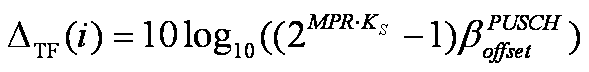
Equation 19
수학식 19에서, deltaMCS-Enabled 파라미터가 1인 경우  로 주어지고, deltaMCS-Enabled 파라미터가 0인 경우에는
  으로 주어진다. deltaMCS-Enabled파라미터 설정 여부는 상위 레이어에서 시그널링될 수 있다.In Equation 19, when the deltaMCS-Enabled parameter is 1 Given by and the deltaMCS-Enabled parameter is 0 Given by Whether to set the deltaMCS-Enabled parameter may be signaled in a higher layer.
수학식 19에서 MPR은 아래 수학식 20과 같이 표현될 수 있다.In Equation 19, MPR may be expressed as Equation 20 below.
수학식 20 
Equation 20
수학식 20을 참조하면, MPR은 상향링크 공유채널 데이터 없이 PUSCH를 통하여 제어 정보를 전송하는 경우에는 CRC 비트를 포함하는 CQI비트의 수를 자원 요소의 수로 나눈 값이 되고, 그렇지 않은 경우  로 결정될 수 있다.Referring to
 Equation 20, when the control information is transmitted through the PUSCH without uplink shared channel data, the MPR is a value obtained by dividing the number of CQI bits including the CRC bit by the number of resource elements. Can be determined.
여기서 C값은 코드블록의 수를 나타내고,  은 코드블록 r의 크기를 나타낸다. 결국, 일반적인 상황에서MPR의 값은 C 개의 코드블록 전체의 크기를 자원요소(RE)의 개수로 나눈 값이 된다.Where the C value represents the number of code blocks, Denotes the size of code block r. As a result, in a general situation, the value of MPR is obtained by dividing the total size of the C code blocks by the number of resource elements RE.
상향링크 공유채널 데이터 없이 PUSCH를 통하여 제어 정보를 전송하는 경우 로 설정되며, 나머지 경우
  값은 1이 된다.When control information is transmitted through PUSCH without uplink shared channel data Is set to The value is 1.
마지막으로 f(i)는 폐루프 방식의 보정 값으로, 데시벨 단위로 이전 값을 수정하는 방법으로 조정될 수 있다. f(i)에는 하향링크 제어 정보 포맷(DCI format) 0, 3 또는 3A가 사용될 수 있다.Finally, f ( i ) is a closed loop correction value, which can be adjusted by modifying the previous value in decibel units. Downlink control information format (DCI format 0, 3 or 3A) may be used for f ( i ).
지금까지 수학식 15 내지 20을 참조하여 상향링크 전송전력 제어 방법들을 설명하였다. 그런데, 상술한 상향링크 전송전력 제어 방법들은 단일 안테나 환경에 적용되는 것으로, 둘 이상의 안테나를 지원하는 MIMO 환경에서는 전송전력을 제어하는 방법이 정의될 필요가 있다.Uplink transmission power control methods have been described with reference to Equations 15 to 20. However, the above-described uplink transmission power control methods are applied to a single antenna environment, and a method for controlling the transmission power needs to be defined in a MIMO environment supporting two or more antennas.
상술한 바와 같이, MIMO 환경에서는 두 가지 전송 모드가 존재한다. 그 중 하나는 전송 다이버시티 모드(transmit diversity mode)이고, 다른 하나는 공간 멀티플렉싱 모드(spatial multiplexing mode)이다. As described above, there are two transmission modes in the MIMO environment. One of them is a transmit diversity mode and the other is a spatial multiplexing mode.
먼저, 전송 다이버시티 모드에서 상향링크 데이터 채널의 전송전력 제어를 설명한다. First, transmission power control of an uplink data channel in transmission diversity mode will be described.
전송 다이버시티 모드에서 데이터 채널의 전송전력을 제어하는 방법은 단일 안테나 상황에서 전송전력을 제어하는 방법과 동일할 수 있다. 따라서, 전송 다이버시티 모드에서의 전송전력은 수학식 15또는 수학식 18과 같은 방법으로 제어될 수 있다. 이러한 전송전력 제어 방법이 안테나 그룹 선택에 적용되는 경우, 선택되지 않은 안테나 그룹의 전송전력은 오프 레벨(off-level)이 되고, 선택된 안테나 그룹의 전송전력은 수학식 15 또는 수학식 18과 같이 제어될 수 있다.The method of controlling the transmit power of the data channel in the transmit diversity mode may be the same as the method of controlling the transmit power in a single antenna situation. Therefore, the transmission power in the transmission diversity mode can be controlled by the method as in Equation 15 or Equation 18. When the transmission power control method is applied to antenna group selection, the transmission power of the unselected antenna group is off-level, and the transmission power of the selected antenna group is controlled as in Equation 15 or Equation 18. Can be.
다음으로, 공간 멀티플렉싱 모드의 경우를 설명한다.Next, the case of the spatial multiplexing mode will be described.
공간 멀티플렉싱 모드의 경우에도 수학식 15 또는 수학식 18의 전송전력 제어방법이 적용될 수 있다. 다만, 공간 멀티플렉싱 모드에서는 안테나 별로 서로 다른 데이터가 전송될 수 있다.Even in the spatial multiplexing mode, the transmission power control method of Equation 15 or Equation 18 may be applied. However, in spatial multiplexing mode, different data may be transmitted for each antenna.
따라서, 본 발명에서는 공간 멀티플렉싱 모드에서 상향링크 데이터 채널의 전송전력을 제어하는데 있어 랭크를 더욱 고려할 것을 제안한다.Therefore, the present invention proposes to consider the rank further in controlling the transmission power of the uplink data channel in the spatial multiplexing mode.
1. One.
"deltaMCS-Enabled" "deltaMCS-Enabled"
이 설정되지 않은 경우Is not set
본 실시예의 일 양상에서는 "deltaMCS-Enabled"이 설정되지 않은 경우, 즉,  가 0으로 설정되는 경우, 수학식 15를 아래 수학식 21과 같이 수정할 것을 제안한다.In one aspect of the present embodiment, when "deltaMCS-Enabled" is not set, that is, If is set to 0, it is proposed to modify Equation 15 as Equation 21 below.
수학식 21은 본 발명의 일 실시예에 따른 전송전력 제어방법의 일례를 나타낸다.Equation 21 shows an example of a transmission power control method according to an embodiment of the present invention.
수학식 21 
Equation 21
수학식 21에서  는 랭크를 고려하여 PDCCH 또는 상위 레이어를 통하여 시그널링되는 값일 수 있다. In Equation 21 May be a value signaled through the PDCCH or higher layer in consideration of the rank.
만일, 수학식 18을 수정하는 경우 수학식 21의 P
MAX는 P
CMAX로 대체될 수 있다.If Equation 18 is modified, P MAX in Equation 21 may be replaced with P CMAX .
2. 2.
"deltaMCS-Enabled""deltaMCS-Enabled"
이 설정된 경우.If is set.
본 실시예의 다른 양상에서는 "deltaMCS-Enabled"이 설정된 경우에  의 정의를 수정할 것을 제안한다.In another aspect of the present embodiment, when "deltaMCS-Enabled" is set, It is suggested to modify the definition of.
단일 안테나를 사용하는 경우와는 달리, 전송 랭크에 따라 수학식 16 또는 수학식 19의 값의 범위가 커질 수 있다. 따라서, 본 실시예의 다른 양상에서는 전송 랭크를 고려하여 전송전력을 제어하는 방법으로 아래와 같이 세 가지를 제안한다.Unlike the case of using a single antenna, the range of the value of Equation 16 or 19 may be increased according to the transmission rank. Therefore, in another aspect of the present embodiment, three methods as follows are proposed as a method of controlling the transmission power in consideration of the transmission rank.
1). 랭크 별로  를 개별적으로 재정의하는 방법.One). By rank How to redefine them individually.
2).  의 재정의와 함께 랭크에 종속되는 보정 값(correction term)을 추가하는 방법.2). How to add a rank-dependent correction term with the redefinition of.
3). 다중 안테나 환경에 유니버설하게 적용될 수 있는 하나의  를 재정의하는 방법.3). One universally applicable to multi-antenna environments How to redefine it.
먼저, 첫 번째 방법인 랭크 별로  를 개별적으로 재정의하는 방법을 설명한다.First, by rank, the first method Describe how to redefine them individually.
랭크 별로  를 개별적으로 재정의한다고 함은,
  에 랭크에 종속되는(rank-dependent) 변수를 추가함을 의미한다. 이 경우, 수학식 15는 아래 수학식 22와 같이 수정될 수 있다.By rank By redefining separately, This means adding a rank-dependent variable to the. In this case, Equation 15 may be modified as in Equation 22 below.
수학식 22는 본 발명의 일 실시예에 따른 전송전력 제어방법의 다른 일례를 나타낸다.Equation 22 shows another example of a transmission power control method according to an embodiment of the present invention.
수학식 22 
Equation 22
수학식 22에서  는 i번째 서브프레임에서 전송랭크l 에 대응되는 값을 의미한다. 수학식 18을 수정하는 경우에는 수학식 22의 P
MAX는 P
CMAX로 대체될 수 있으며,
는 i번째 서브프레임에서 전송랭크l 에 대응되는 값을 의미한다. 수학식 18을 수정하는 경우에는 수학식 22의 P
MAX는 P
CMAX로 대체될 수 있으며,  에서 MPR의 정의도 수학식 18과 유사한 형태(즉, 전송블록사이즈가 전체 코드블록사이즈로 대체)로 변경될 수 있다.In Equation 22 Denotes a value corresponding to the transmission rank l in the i- th subframe. When modifying Equation 18, P MAX in Equation 22 may be replaced with P CMAX . The definition of MPR may also be changed to a form similar to Equation 18 (ie, the transport block size is replaced with the entire code block size).
다음으로, 두 번째 방법인  의 재정의와 함께 랭크에 종속되는 보정 값(correction term)을 추가하는 방법을 설명한다.Next, the second method We will explain how to add a correction term that is dependent on a rank with the redefinition of.
본 실시예에 따른 랭크에 종속되는 보정 값을 고려한 전력제어 방법은 아래 수학식 23과 같이 표현될 수 있다.The power control method in consideration of the correction value dependent on the rank according to the present embodiment may be expressed by Equation 23 below.
수학식 23 
Equation 23
수학식 23을 참조하면,  가 수학식 15에서 추가되었다. 추가된
  는 i번째 서브프레임의 전송 랭크에 종속되는(rank-dependent) 값이며,
  는 수학식 18 또는 수학식 16, 수학식 19 또는 수학식 22의
  중 어느 하나와 동일하거나 상이하게 설정될 수 있다. 수학식 15가 아닌 수학식 18을 수정하는 경우에는 수학식 23의 P
MAX는 P
CMAX로 대체될 수 있으며,
중 어느 하나와 동일하거나 상이하게 설정될 수 있다. 수학식 15가 아닌 수학식 18을 수정하는 경우에는 수학식 23의 P
MAX는 P
CMAX로 대체될 수 있으며,  에서 MPR의 정의도 수학식 18과 유사한 형태(즉, 전송블록사이즈가 전체 코드블록사이즈로 대체)로 변경될 수 있다.Referring to Equation 23, Was added in (15). Added Is a rank-dependent value of the transmission rank of the i th subframe, Is expressed by Equation 18 or Equation 16, Equation 19 or Equation 22, It may be set equal to or different from either. When modifying Equation 18 rather than Equation 15, P MAX in Equation 23 may be replaced with P CMAX . The definition of MPR may also be changed to a form similar to Equation 18 (ie, the transport block size is replaced with the entire code block size).
한편,  값은 상위 레이어 또는 제어채널(예를 들어, PDCCH)를 통하여 시그널링될 수 있다. 이때,
  를 수학식 15와 같이 rank에 따라 달라지지 않는 값이라고 가정하면,
  은 더 많은 송신 전력을 요구하게 된다. 이는 rank가 증가할수록 높은 data 전송율에 해당하는 데이터 블록을 전송하게 되므로, 더 큰 송신 전력이 요구된다.
  를 rank에 따라 달라지는 값으로 가정하면,
  의 전력 가변 범위는 앞의
  가 rank에 따라 가변하는 경우에 비해서 작게 된다. 이 때,
  는 rank에 따라 달라지지 않는 상수 값일 수 있다.Meanwhile, The value may be signaled through an upper layer or a control channel (eg, PDCCH). At this time, If we assume that the value does not depend on the rank as in Equation 15, Will require more transmit power. As the rank increases, a data block corresponding to a high data rate is transmitted, so that a larger transmission power is required. Is assumed to be a rank-dependent value, Power variable range of the front Is smaller than the case of varying according to rank. At this time, May be a constant value that does not depend on rank.
마지막으로 세 번째 방법인, 다중 안테나 환경에 유니버설하게 적용될 수 있는 하나의  를 재정의하는 방법을 설명한다.Finally, a third approach, one that can be universally applied to a multi-antenna environment Describe how to redefine it.
본 방법에서 기본적으로 전송전력을 제어하는 방법은 수학식 15또는 수학식 18과 유사하다. 다만,  는 공간 멀티플렉싱 모드에 적합하도록 변경되는 것이 바람직하다.In the present method, the method of controlling the transmission power is basically similar to the equation (15) or (18). but, Is preferably changed to suit the spatial multiplexing mode.
본 방법의 다른 예로, 랭크가 1인 경우에는 전송전력을 제어하는 방법으로 수학식 15 또는 수학식 18을 사용하되, 2이상의 랭크에 대해서는  를 0으로 설정할 수 있다. 이때, 랭크 1에 적용되는
  는 수학식 16과 상이할 수 있다.As another example of the method, when the rank is 1, Equation 15 or Equation 18 is used as a method of controlling the transmission power, but for a rank of 2 or more Can be set to 0. At this time, rank 1 May be different from equation (16).
보다 구체적으로, 공간 멀티플렉싱 모드에서 다중 전송 블록을 지원하는 경우 수학식 17에 나타난 바와 같은 MPR의 정의는 아래 수학식 24와 같이 변경될 수 있다.More specifically, in the case of supporting multiple transport blocks in the spatial multiplexing mode, the definition of the MPR as shown in Equation 17 may be changed as shown in Equation 24 below.
수학식 24 
Equation 24
수학식 24에서 TBSk는 k번째 전송 블럭의 크기를 나타낸다. 즉, MPR은 전체 전송 블록의 크기를 자원요소의 수로 나눈 값이 된다. 한편, 본 방법의 다른 양상에 의하면 수학식 24에서 전송 블록은 코드 블록으로 대체될 수 있다. 즉, MPR은 전체 코드 블록의 크기를 자원요소의 수로 나눈 값이 될 수도 있다.In Equation 24, TBS k represents the size of the k th transport block. That is, the MPR is a value obtained by dividing the size of the entire transport block by the number of resource elements. Meanwhile, according to another aspect of the present method, the transport block in Equation 24 may be replaced with a code block. That is, the MPR may be a value obtained by dividing the size of the entire code block by the number of resource elements.
만일, 스케쥴링 그랜트(scheduling grant) 없이 재전송 상황이 발생하는 경우 제어 정보의 코드화된 비트의 수(the number of coded bits of control information)는 최초 PDCCH의 정보(즉, 자원 할당 정보)를 따를 수 있다. 따라서, 이러한 경우 MPR 의 정의는 수학식 17에 나타난 바와 동일할 수 있다.If a retransmission situation occurs without a scheduling grant, the number of coded bits of control information may follow information of the initial PDCCH (ie, resource allocation information). Therefore, in this case, the definition of MPR may be the same as that shown in Equation 17.
결국, 소형 단말기의 전송 안테나는 공간적 한계로 서로 다른 전송 안테나 이득을 가질 수 있으며, 이는 성능 열화를 가져올 수 있다. 특히, 큰 신호대잡음비(SNR) 편차가 채널 디코더로 입력되는 경우 불균등한 안테나 이득으로 인하여 채널 디코더 성능이 저하될 수 있다. 이러한 불균등은 수신단에서 장기간 채널 특성(long-term channel characteristics)으로 관측될 수 있다. 따라서, 본 발명에서는 상술한 실시예들을 통하여 이러한 불균등한 안테나 이득을 보정하기 위한 전력 오프셋 값을 적용할 것을 제안한 것이다. 이러한 전력 오프셋 값은 상위 레이어 시그널링을 통하여 주어지는 것이 바람직하다.As a result, the transmit antennas of the small terminal may have different transmit antenna gains due to spatial limitations, which may lead to performance degradation. In particular, when a large signal-to-noise ratio (SNR) deviation is input to the channel decoder, channel decoder performance may be degraded due to uneven antenna gain. This inequality may be observed as long-term channel characteristics at the receiving end. Accordingly, the present invention proposes to apply a power offset value for correcting such uneven antenna gain through the above-described embodiments. Such a power offset value is preferably given through higher layer signaling.
단말 및 기지국Terminal and base station
본 발명의 다른 실시예로서, 상술한 본 발명의 실시예들이 수행될 수 있는 단말 및 기지국(FBS, MBS)을 설명한다.As another embodiment of the present invention, a terminal and a base station (FBS, MBS) in which the above-described embodiments of the present invention can be performed are described.
단말은 상향링크에서는 송신기로 동작하고, 하향링크에서는 수신기로 동작할 수 있다. 또한, 기지국은 상향링크에서는 수신기로 동작하고, 하향링크에서는 송신기로 동작할 수 있다. 즉, 단말 및 기지국은 정보 또는 데이터의 전송을 위해 송신기 및 수신기를 포함할 수 있다.The terminal may operate as a transmitter in uplink and operate as a receiver in downlink. In addition, the base station may operate as a receiver in the uplink, and may operate as a transmitter in the downlink. That is, the terminal and the base station may include a transmitter and a receiver for transmitting information or data.
송신기 및 수신기는 본 발명의 실시예들이 수행되기 위한 프로세서, 모듈, 부분 및/또는 수단 등을 포함할 수 있다. 특히, 송신기 및 수신기는 메시지를 암호화하기 위한 모듈(수단), 암호화된 메시지를 해석하기 위한 모듈, 메시지를 송수신하기 위한 안테나 등을 포함할 수 있다. 이러한 송신단과 수신단의 일례를 도 6을 참조하여 설명한다. The transmitter and receiver may include a processor, module, part, and / or means for carrying out the embodiments of the present invention. In particular, the transmitter and receiver may include a module (means) for encrypting the message, a module for interpreting the encrypted message, an antenna for transmitting and receiving the message, and the like. An example of such a transmitter and a receiver will be described with reference to FIG.
도 6은 본 발명의 다른 실시예로서, 송신단 및 수신단 구조의 일례를 나타내는 블록도이다. 6 is a block diagram illustrating an example of a structure of a transmitting end and a receiving end according to another embodiment of the present invention.
도 6을 참조하면, 좌측은 송신단의 구조를 나타내고, 우측은 수신단의 구조를 나타낸다. 송신단과 수신단 각각은 안테나(5, 10), 프로세서(20, 30), 전송모듈(Tx module(40, 50)), 수신모듈(Rx module(60, 70)) 및 메모리(80, 90)를 포함할 수 있다. 각 구성 요소는 서로 대응되는 기능을 수행할 수 있다. 이하 각 구성요소를 보다 상세히 설명한다. Referring to FIG. 6, the left side shows the structure of the transmitter and the right side shows the structure of the receiver. Each of the transmitting end and the receiving end includes an antenna 5, 10, a processor 20, 30, a transmission module (Tx module 40, 50), a receiving module (Rx module 60, 70) and a memory 80, 90. It may include. Each component may perform a function corresponding to each other. Hereinafter, each component will be described in more detail.
안테나(5, 10)는 전송모듈(40, 50)에서 생성된 신호를 외부로 전송하거나, 외부로부터 무선 신호를 수신하여 수신모듈(60, 70)로 전달하는 기능을 수행한다. 다중 안테나(MIMO) 기능이 지원되는 경우에는 2개 이상이 구비될 수 있다. The antennas 5 and 10 transmit the signals generated by the transmission modules 40 and 50 to the outside, or receive the radio signals from the outside and transmit the signals to the receiving modules 60 and 70. When the multiple antenna (MIMO) function is supported, two or more may be provided.
안테나, 전송모듈 및 수신모듈은 함께 무선통신(RF) 모듈을 구성할 수 있다. The antenna, the transmission module and the reception module may together constitute a radio communication (RF) module.
프로세서(20, 30)는 통상적으로 이동 단말기 전체의 전반적인 동작을 제어한다. 예를 들어, 상술한 본 발명의 실시예들을 수행하기 위한 콘트롤러 기능, 서비스 특성 및 전파 환경에 따른 MAC(Medium Access Control) 프레임 가변 제어 기능, 핸드오버(Hand Over) 기능, 인증 및 암호화 기능 등이 수행될 수 있다. 보다 구체적으로, 프로세서(20, 30)는 상술한 전송전력 제어를 위한 전반적인 제어를 수행할 수 있다. Processors 20 and 30 typically control the overall operation of the entire mobile terminal. For example, a controller function for performing the above-described embodiments of the present invention, a medium access control (MAC) frame variable control function, a handover function, an authentication and encryption function, etc. according to service characteristics and a propagation environment may be used. Can be performed. More specifically, the processors 20 and 30 may perform overall control for the transmission power control described above.
예를 들어, 이동 단말기의 프로세서는 데이터 채널의 상향링크 전송 전력을 수학식 15 내지 24를 이용하여 결정할 수 있다. 특히, 프로세서는 MIMO 방식 중 공간 멀티플렉싱 모드에서 전송 랭크를 고려하여 상향링크 데이터 채널의 전송 전력을 결정할 수 있다. 프로세서는 송신 모듈을 제어하여 결정된 전송 전력이 상향링크 데이터 채널의 전송에 적용되도록 할 수 있다. 이 외에도 단말의 프로세서는 상술한 실시예들에 개시된 동작 과정의 전반적인 제어 동작을 수행할 수 있다. For example, the processor of the mobile terminal may determine the uplink transmit power of the data channel using Equations 15 to 24. In particular, the processor may determine the transmission power of the uplink data channel in consideration of the transmission rank in the spatial multiplexing mode of the MIMO scheme. The processor may control the transmission module so that the determined transmission power is applied to the transmission of the uplink data channel. In addition, the processor of the terminal may perform the overall control operation of the operation process disclosed in the above embodiments.
전송 모듈(40, 50)은 프로세서(20, 30)로부터 스케쥴링되어 외부로 전송될 데이터에 대하여 소정의 부호화(coding) 및 변조(modulation)를 수행한 후 안테나(10)에 전달할 수 있다. 특히, 이동 단말의 전송 모듈은 하나 이상의 코드워드를 하나 이상의 스트림에 맵핑시키는 코드워드-스트림 맵핑 모듈과 코드워드-스트림 맵핑 모듈로부터 출력되는 하나 이상의 스트림을 복수의 안테나에 맵핑시키는 스트림-안테나 맵핑 모듈을 포함할 수 있다.The transmission modules 40 and 50 may perform a predetermined encoding and modulation on data scheduled from the processors 20 and 30 to be transmitted to the outside, and then transmit the data to the antenna 10. In particular, the transmission module of the mobile terminal includes a codeword-stream mapping module for mapping one or more codewords to one or more streams and a stream-antenna mapping module for mapping one or more streams output from the codeword-stream mapping module to a plurality of antennas. It may include.
수신 모듈(60, 70)은 외부에서 안테나(5, 10)를 통하여 수신된 무선 신호에 대한 복호(decoding) 및 복조(demodulation)을 수행하여 원본 데이터의 형태로 복원하여 프로세서(20, 30)로 전달할 수 있다. The receiving module 60, 70 decodes and demodulates a radio signal received through the antennas 5, 10 from the outside to restore the original data to the processor 20, 30. I can deliver it.
메모리(80, 90)는 프로세서(20, 30)의 처리 및 제어를 위한 프로그램이 저장될 수도 있고, 입/출력되는 데이터들의 임시 저장을 위한 기능을 수행할 수도 있다. 또한, 메모리(80, 90)는 플래시 메모리 타입(flash memory type), 하드디스크 타입(hard disk type), 멀티미디어 카드 마이크로 타입(multimedia card micro type), 카드 타입의 메모리(예를 들어 SD 또는 XD 메모리 등), 램(Random Access Memory, RAM), SRAM(Static Random Access Memory), 롬(Read-Only Memory, ROM), EEPROM(Electrically Erasable Programmable Read-Only Memory), PROM(Programmable Read-Only Memory), 자기 메모리, 자기 디스크, 광디스크 중 적어도 하나의 타입의 저장매체를 포함할 수 있다. The memory 80, 90 may store a program for processing and controlling the processor 20, 30, or may perform a function for temporarily storing input / output data. In addition, the memory 80, 90 may be a flash memory type, a hard disk type, a multimedia card micro type, a card type memory (eg, SD or XD memory). Etc.), random access memory (RAM), static random access memory (SRAM), read-only memory (ROM), electrically erasable programmable read-only memory (EPEROM), programmable read-only memory (PROM), At least one type of storage medium may include a magnetic memory, a magnetic disk, and an optical disk.
한편, 기지국은 상술한 본 발명의 실시예들을 수행하기 위한 콘트롤러 기능, 직교주파수분할다중접속(OFDMA: Orthogonal Frequency Division Multiple Access) 패킷 스케줄링, 시분할듀플렉스(TDD: Time Division Duplex) 패킷 스케줄링 및 채널 다중화 기능, 서비스 특성 및 전파 환경에 따른 MAC 프레임 가변 제어 기능, 고속 트래픽 실시간 제어 기능, 핸드오버(Handover) 기능, 인증 및 암호화 기능, 데이터 전송을 위한 패킷 변복조 기능, 고속 패킷 채널 코딩 기능 및 실시간 모뎀 제어 기능 등이 상술한 모듈 중 적어도 하나를 통하여 수행하거나, 이러한 기능을 수행하기 위한 별도의 수단, 모듈 또는 부분 등을 더 포함할 수 있다. On the other hand, the base station is a controller function for performing the above-described embodiments of the present invention, orthogonal frequency division multiple access (OFDMA) packet scheduling, time division duplex (TDD) packet scheduling and channel multiplexing function MAC frame variable control function according to service characteristics and propagation environment, high speed traffic real time control function, handover function, authentication and encryption function, packet modulation and demodulation function for data transmission, high speed packet channel coding function and real time modem control function Etc. may be performed through at least one of the above-described modules, or may further include additional means, modules or parts for performing such a function.
본 발명은 본 발명의 정신 및 필수적 특징을 벗어나지 않는 범위에서 다른 특정한 형태로 구체화될 수 있다. 따라서, 상기의 상세한 설명은 모든 면에서 제한적으로 해석되어서는 아니되고 예시적인 것으로 고려되어야 한다. 본 발명의 범위는 첨부된 청구항의 합리적 해석에 의해 결정되어야 하고, 본 발명의 등가적 범위 내에서의 모든 변경은 본 발명의 범위에 포함된다. 또한, 특허청구범위에서 명시적인 인용 관계가 있지 않은 청구항들을 결합하여 실시예를 구성하거나 출원 후의 보정에 의해 새로운 청구항으로 포함할 수 있다. The invention can be embodied in other specific forms without departing from the spirit and essential features of the invention. Accordingly, the above detailed description should not be construed as limiting in all aspects and should be considered as illustrative. The scope of the invention should be determined by reasonable interpretation of the appended claims, and all changes within the equivalent scope of the invention are included in the scope of the invention. In addition, the claims may be incorporated into claims that do not have an explicit citation relationship in the claims, or may be incorporated into new claims by post-application correction.
본 발명의 실시예들은 다양한 무선접속 시스템에 적용될 수 있다. 다양한 무선접속 시스템들의 일례로서, 3GPP(3rd Generation Partnership Project), 3GPP2 및/또는 IEEE 802.xx (Institute of Electrical and Electronic Engineers 802) 시스템 등이 있다. 본 발명의 실시예들은 상기 다양한 무선접속 시스템뿐 아니라, 상기 다양한 무선접속 시스템을 응용한 모든 기술 분야에 적용될 수 있다.Embodiments of the present invention can be applied to various wireless access systems. Examples of various radio access systems include 3rd Generation Partnership Project (3GPP), 3GPP2 and / or IEEE 802.xx (Institute of Electrical and Electronic Engineers 802) systems. Embodiments of the present invention can be applied not only to the various radio access systems, but also to all technical fields to which the various radio access systems are applied.
Claims (20)
- 복수의 전송 랭크를 지원하는 송신단에서 상향링크 데이터 채널의 전송전력 제어를 수행하는 방법에 있어서,A method of performing transmission power control of an uplink data channel in a transmitting end supporting a plurality of transmission ranks,특정 서브프레임에서의 전송 랭크에 종속되는 적어도 하나의 랭크 변수를 이용하여 제 1 전송 전력을 결정하는 단계; Determining a first transmit power using at least one rank variable that is dependent on a transmit rank in a particular subframe;기 설정된 최대 전송 전력인 제 2 전송 전력과 상기 결정된 제 1 전송 전력을 비교하는 단계; 및Comparing a second transmission power that is a preset maximum transmission power with the determined first transmission power; And상기 비교 결과 적은 값을 상기 데이터 채널의 전송전력으로 결정하는 단계를 포함하는, 전송 전력 제어방법.And determining a smaller value as a result of the comparison as the transmission power of the data channel.
- 제 1항에 있어서,The method of claim 1,상기 제 1 전송 전력을 결정하는 단계는, Determining the first transmit power,전송 경로 손실 보상 변수, 상기 데이터 채널의 대역폭, 폐루프 방식의 전력 보정 변수 및 상위 레이어에서 결정한 기준 전력 중 적어도 하나를 더 이용하여 수행되는 것을 특징으로 하는 전송 전력 제어방법.And at least one of a transmission path loss compensation variable, a bandwidth of the data channel, a closed loop power correction variable, and a reference power determined by an upper layer.
- 제 2항에 있어서,The method of claim 2,상기 랭크 변수는,The rank variable is,랭크 별로 설정되는 전력 보정을 위한 오프셋 값인 것을 특징으로 하는 전송 전력 제어방법.The transmission power control method, characterized in that the offset value for the power correction is set for each rank.
- 제 3항에 있어서,The method of claim 3,상기 오프셋 값은,The offset value is,상위 레이어 시그널링 또는 제어채널을 통하여 결정되는 것을 특징으로 하는 전송 전력 제어방법.Transmission power control method characterized in that determined through the upper layer signaling or control channel.
- 제 2항에 있어서,The method of claim 2,상기 랭크 변수는,The rank variable is,동적 채널 변화에 대한 변조 및 코딩 기법(MCS)을 통한 전력 보상을 위한 파라미터인 것을 특징으로 하는 전송 전력 제어방법.And a parameter for power compensation through a modulation and coding scheme (MCS) for dynamic channel change.
- 제 5항에 있어서,The method of claim 5,상기 파라미터는, The parameter is상기 서브 프레임에서 전송되는 데이터의 크기를 자원 요소의 수로 나눈 값을 이용하여 결정되는, 전송 전력 제어방법.And a size of data transmitted in the subframe is determined by dividing the number of resource elements by the number of resource elements.
- 제 6항에 있어서,The method of claim 6,상기 전송되는 데이터의 크기는,The size of the transmitted data is,상기 서브 프레임에서 전송되는 각 데이터 단위 블록 크기의 총합인 것을 특징으로 하는 전송 전력 제어 방법.The total power of the data unit block size transmitted in the sub-frame, characterized in that the transmission power control method.
- 제 7항에 있어서,The method of claim 7, wherein상기 데이터 단위 블록은The data unit block is전송 블록(transport block) 또는 코드 블록(code block)인 것을 특징으로 하는 전송 전력 제어 방법.A transmission power control method, characterized in that the transport block (code block) or a code block (code block).
- 제 2항에 있어서,The method of claim 2,상기 데이터 채널의 전송은,The transmission of the data channel,공간 멀티플렉싱(spatial multiplexing) 방식으로 수행되는 것을 특징으로 하는 전송 전력 제어방법.A transmission power control method, characterized in that performed in a spatial multiplexing (spatial multiplexing) method.
- 제 2항에 있어서,The method of claim 2,상기 상위 레이어에서 결정한 기준 전력은,The reference power determined by the upper layer is,단말 특정(UE specific) 값과 셀 특정(cell-specific) 값의 합으로 결정되는 것을 특징으로 하는 전송 전력 제어방법.A transmission power control method characterized in that it is determined by the sum of a UE specific value and a cell-specific value.
- 제 2항에 있어서,The method of claim 2,상기 상향링크 데이터 채널은, The uplink data channel,물리 상향링크 공유 채널(PUSCH)인 것을 특징으로 하는 전송 전력 제어방법. And a physical uplink shared channel (PUSCH).
- 복수의 전송 랭크를 지원하는 이동 단말기에 있어서, In a mobile terminal supporting a plurality of transmission ranks,프로세서; 및 A processor; And상기 프로세서의 제어에 따라 외부와 무선 신호를 송수신하기 위한 무선통신(RF) 모듈을 포함하되, Including a radio communication (RF) module for transmitting and receiving a radio signal with the outside under the control of the processor,상기 프로세서는, The processor,특정 서브프레임에서의 전송 랭크에 종속되는 적어도 하나의 랭크 변수를 이용하여 제 1 전송 전력을 결정하고, 기 설정된 최대 전송 전력인 제 2 전송 전력과 상기 결정된 제 1 전송 전력을 비교하여 그 중 적은 값을 데이터 채널의 전송전력으로 결정하며, 상기 결정된 전송전력으로 상기 데이터 채널의 전송이 수행되도록 상기 무선 통신 모듈을 제어하는 것을 특징으로 하는, 이동 단말기.The first transmission power is determined using at least one rank variable that is dependent on the transmission rank in a specific subframe, and the second transmission power, which is a preset maximum transmission power, is compared with the determined first transmission power, and a smaller value thereof. Is determined as the transmission power of the data channel, and the wireless communication module is controlled to perform the transmission of the data channel at the determined transmission power.
- 제 12항에 있어서,The method of claim 12,상기 프로세서는,The processor,전송 경로 손실 보상 변수, 상기 데이터 채널의 대역폭, 폐루프 방식의 전력 보정 변수 및 상위 레이어에서 결정한 기준 전력 중 적어도 하나를 더 이용하여 상기 제 1 전송 전력을 결정하는 것을 특징으로 하는 이동 단말기.And determining the first transmission power by using at least one of a transmission path loss compensation variable, a bandwidth of the data channel, a closed loop power correction variable, and a reference power determined by an upper layer.
- 제 13항에 있어서,The method of claim 13,상기 랭크 변수는,The rank variable is,전송 랭크 별로 설정되는 전력 보정을 위한 오프셋 값인 것을 특징으로 하는 이동 단말기.The mobile terminal, characterized in that the offset value for the power correction is set for each transmission rank.
- 제 14항에 있어서,The method of claim 14,상기 오프셋 값은,The offset value is,상위 레이어 시그널링 또는 제어채널을 통하여 결정되는 것을 특징으로 하는 이동 단말기.A mobile terminal, characterized in that determined through higher layer signaling or control channel.
- 제 13항에 있어서,The method of claim 13,상기 랭크 변수는,The rank variable is,동적 채널 변화에 대한 변조 및 코딩 기법(MCS)을 통한 전력 보상을 위한 파라미터인 것을 특징으로 하는 이동 단말기.And a parameter for power compensation through a modulation and coding scheme (MCS) for dynamic channel change.
- 제 16항에 있어서,The method of claim 16,상기 파라미터는, The parameter is상기 서브 프레임에서 전송되는 데이터의 크기를 자원 요소의 수로 나눈 값을 이용하여 결정되는, 이동 단말기.The mobile terminal is determined using a value obtained by dividing the size of data transmitted in the subframe by the number of resource elements.
- 제 17항에 있어서,The method of claim 17,상기 전송되는 데이터의 크기는,The size of the transmitted data is,상기 서브 프레임에서 전송되는 각 데이터 단위 블록 크기의 총합인 것을 특징으로 하는 이동 단말기.The mobile terminal, characterized in that the sum of the block size of each data unit transmitted in the sub-frame.
- 제 18항에 있어서,The method of claim 18,상기 데이터 단위 블록은The data unit block is전송 블록(transport block) 또는 코드 블록(code block)인 것을 특징으로 하는 이동 단말기.A mobile terminal, characterized in that a transport block or a code block.
- 제 13항에 있어서,The method of claim 13,상기 데이터 채널의 전송은,The transmission of the data channel,공간 멀티플렉싱(spatial multiplexing) 방식으로 수행되는 것을 특징으로 하는 이동 단말기.A mobile terminal characterized in that it is performed by a spatial multiplexing scheme.
Priority Applications (1)
| Application Number | Priority Date | Filing Date | Title |
|---|---|---|---|
| US13/202,703 US8812045B2 (en) | 2009-03-09 | 2010-03-09 | Method for controlling transmission power in a multi-antenna wireless communication system |
Applications Claiming Priority (4)
| Application Number | Priority Date | Filing Date | Title |
|---|---|---|---|
| US15872609P | 2009-03-09 | 2009-03-09 | |
| US61/158,726 | 2009-03-09 | ||
| KR10-2010-0020742 | 2010-03-09 | ||
| KR1020100020742A KR101595031B1 (en) | 2009-03-09 | 2010-03-09 | Method for controlling transmission power in a wireless communication system supporting multiple antennas |
Publications (2)
| Publication Number | Publication Date |
|---|---|
| WO2010104313A2 true WO2010104313A2 (en) | 2010-09-16 |
| WO2010104313A3 WO2010104313A3 (en) | 2010-12-09 |
Family
ID=42728933
Family Applications (1)
| Application Number | Title | Priority Date | Filing Date |
|---|---|---|---|
| PCT/KR2010/001459 WO2010104313A2 (en) | 2009-03-09 | 2010-03-09 | Method for controlling transmission power in a multi-antenna wireless communication system |
Country Status (3)
| Country | Link |
|---|---|
| US (1) | US8812045B2 (en) |
| KR (1) | KR101595031B1 (en) |
| WO (1) | WO2010104313A2 (en) |
Cited By (2)
| Publication number | Priority date | Publication date | Assignee | Title |
|---|---|---|---|---|
| WO2013004007A1 (en) * | 2011-07-05 | 2013-01-10 | Renesas Mobile Corporation | Mechanism for enhancing power control in time division based communications |
| CN103686971B (en) * | 2012-09-19 | 2017-09-29 | 联芯科技有限公司 | The method and apparatus of LTE system uplink transmission power control |
Families Citing this family (7)
| Publication number | Priority date | Publication date | Assignee | Title |
|---|---|---|---|---|
| KR101481584B1 (en) * | 2008-06-24 | 2015-01-13 | 엘지전자 주식회사 | Method For Specifying Transport Block to Codeword Mapping And Downlink Signal Transmission Method Using The Same |
| WO2012067429A2 (en) * | 2010-11-16 | 2012-05-24 | 엘지전자 주식회사 | Method for controlling uplink transmission power for transmitting a plurality of codewords in a wireless communication system that supports a plurality of antennas, and apparatus for performing the method |
| KR20120129632A (en) * | 2011-05-20 | 2012-11-28 | 삼성전자주식회사 | Method and apparatus for controlling power in a wireless communication system |
| EP2693813B1 (en) | 2011-07-13 | 2018-10-03 | Sun Patent Trust | Terminal apparatus, base station apparatus, transmission method and reception method |
| KR101781885B1 (en) * | 2013-10-31 | 2017-09-26 | 엘지전자 주식회사 | Broadcast channel transmitting method through massive mimo in wireless communication system and apparatus therefor |
| CN106664588B (en) * | 2014-07-02 | 2020-08-21 | 瑞典爱立信有限公司 | Method and network node for calibrating beamforming for uplink measurements |
| CN107204825B (en) | 2016-03-16 | 2019-07-12 | 华为技术有限公司 | Data transmission method for uplink, data receiver method, sending ending equipment and receiving device |
Citations (4)
| Publication number | Priority date | Publication date | Assignee | Title |
|---|---|---|---|---|
| KR20030087296A (en) * | 2002-05-08 | 2003-11-14 | 이광복 | Wireless communication system employing multi-element antennas at both the transmitter and receiver and method thereof |
| KR20040107787A (en) * | 2003-06-13 | 2004-12-23 | 삼성전자주식회사 | Method and apparatus for determining antenna weights in close-loop transmit diversity system |
| KR100696208B1 (en) * | 2004-12-08 | 2007-03-20 | 한국전자통신연구원 | Transmitter, receiver and method for controlling multiple input multiple output system |
| WO2009023587A2 (en) * | 2007-08-10 | 2009-02-19 | Qualcomm Incorporated | Adaptation of transmit power based on channel quality |
Family Cites Families (5)
| Publication number | Priority date | Publication date | Assignee | Title |
|---|---|---|---|---|
| KR100487221B1 (en) * | 2001-11-23 | 2005-05-03 | 삼성전자주식회사 | Method and apparatus for controlling the transmission power of control information in a mobile communication system |
| JP4423836B2 (en) * | 2002-04-03 | 2010-03-03 | 日本電気株式会社 | Cellular system, communication control method, and mobile station |
| US7986959B2 (en) * | 2007-02-14 | 2011-07-26 | Qualcomm Incorporated | Preamble based uplink power control for LTE |
| US8437792B2 (en) * | 2007-02-14 | 2013-05-07 | Qualcomm Incorporated | Uplink power control for LTE |
| US8422439B2 (en) * | 2008-12-31 | 2013-04-16 | Motorola Mobility Llc | Apparatus and method for communicating control information over a data channel in the absence of user data |
-
2010
- 2010-03-09 US US13/202,703 patent/US8812045B2/en not_active Expired - Fee Related
- 2010-03-09 WO PCT/KR2010/001459 patent/WO2010104313A2/en active Application Filing
- 2010-03-09 KR KR1020100020742A patent/KR101595031B1/en active IP Right Grant
Patent Citations (4)
| Publication number | Priority date | Publication date | Assignee | Title |
|---|---|---|---|---|
| KR20030087296A (en) * | 2002-05-08 | 2003-11-14 | 이광복 | Wireless communication system employing multi-element antennas at both the transmitter and receiver and method thereof |
| KR20040107787A (en) * | 2003-06-13 | 2004-12-23 | 삼성전자주식회사 | Method and apparatus for determining antenna weights in close-loop transmit diversity system |
| KR100696208B1 (en) * | 2004-12-08 | 2007-03-20 | 한국전자통신연구원 | Transmitter, receiver and method for controlling multiple input multiple output system |
| WO2009023587A2 (en) * | 2007-08-10 | 2009-02-19 | Qualcomm Incorporated | Adaptation of transmit power based on channel quality |
Cited By (2)
| Publication number | Priority date | Publication date | Assignee | Title |
|---|---|---|---|---|
| WO2013004007A1 (en) * | 2011-07-05 | 2013-01-10 | Renesas Mobile Corporation | Mechanism for enhancing power control in time division based communications |
| CN103686971B (en) * | 2012-09-19 | 2017-09-29 | 联芯科技有限公司 | The method and apparatus of LTE system uplink transmission power control |
Also Published As
| Publication number | Publication date |
|---|---|
| KR101595031B1 (en) | 2016-02-26 |
| US8812045B2 (en) | 2014-08-19 |
| WO2010104313A3 (en) | 2010-12-09 |
| KR20100101541A (en) | 2010-09-17 |
| US20120008707A1 (en) | 2012-01-12 |
Similar Documents
| Publication | Publication Date | Title |
|---|---|---|
| WO2010104313A2 (en) | Method for controlling transmission power in a multi-antenna wireless communication system | |
| WO2013025051A2 (en) | Method and apparatus for inter-cell interference coordination for transmission point group | |
| WO2020145633A1 (en) | Method and device for allocating transmission power in wireless communication system | |
| WO2011046317A2 (en) | Method and apparatus for mode switching between a multi-cell coordinated communication mode and a single-cell mimo communication mode | |
| WO2018026224A1 (en) | Method for terminal for carrying out uplink communication in wireless communication system, and terminal using method | |
| WO2011149286A2 (en) | Method and apparatus for transceiving control information for uplink multi-antenna transmission | |
| WO2018164452A1 (en) | Method for receiving or transmitting downlink signal in wireless communication system and apparatus for same | |
| WO2012002673A2 (en) | Method and device for transmitting/receiving channel state information in a wireless communication system | |
| WO2013133653A1 (en) | Method for reporting channel state information in wireless communication system, and apparatus therefor | |
| WO2016126063A1 (en) | Method for reporting channel state in wireless communication system, and apparatus therefor | |
| WO2012096476A2 (en) | Method and device for transmitting/receiving downlink reference signal in wireless communication system | |
| WO2013009043A2 (en) | Method and apparatus for transceiving a downlink harq in a wireless communication system | |
| WO2017138802A1 (en) | Method and apparatus for transmitting receipt acknowledgement in wireless communication system | |
| WO2016163819A1 (en) | Method for reporting channel state and apparatus therefor | |
| WO2011014014A2 (en) | Apparatus and method of multi cell cooperation in wireless communication system | |
| WO2012005476A2 (en) | Transmitting device and a method of communicating therewith, and receiving device and a method of communicating therewith | |
| WO2011056043A2 (en) | Efficient control information transmission method and apparatus for supporting multiple antenna transmission technique | |
| WO2011155763A2 (en) | Method and device for transmitting/receiving channel state information in coordinated multipoint communication system | |
| WO2012096532A2 (en) | Method and device for setting channel status information measuring resource in a wireless communication system | |
| WO2016153163A1 (en) | Method and apparatus for transmitting feedback of multi-feedback chain-based channel status information for 3d mimo in a wireless communication system | |
| WO2012134131A2 (en) | Method and apparatus for handing over mobile cell | |
| WO2012105766A2 (en) | Method and apparatus for inter-cell interference coordination in a wireless communication system | |
| WO2018038517A1 (en) | Precoding information signaling method and apparatus for uplink transmission in mobile communication system using a plurality of array antennas | |
| WO2016111524A1 (en) | Method for estimating channel status in wireless communication system, and apparatus therefor | |
| WO2011087275A2 (en) | Method and device for codebook generation and downlink signal transmission in a wireless communication system supporting multiple antennas |
Legal Events
| Date | Code | Title | Description |
|---|---|---|---|
| 121 | Ep: the epo has been informed by wipo that ep was designated in this application |
Ref document number: 10751004 Country of ref document: EP Kind code of ref document: A2 |
|
| WWE | Wipo information: entry into national phase |
Ref document number: 13202703 Country of ref document: US |
|
| NENP | Non-entry into the national phase |
Ref country code: DE |
|
| 122 | Ep: pct application non-entry in european phase |
Ref document number: 10751004 Country of ref document: EP Kind code of ref document: A2 |