WO2010101338A1 - Fabrication method for capacitor electrode - Google Patents
Fabrication method for capacitor electrode Download PDFInfo
- Publication number
- WO2010101338A1 WO2010101338A1 PCT/KR2009/004261 KR2009004261W WO2010101338A1 WO 2010101338 A1 WO2010101338 A1 WO 2010101338A1 KR 2009004261 W KR2009004261 W KR 2009004261W WO 2010101338 A1 WO2010101338 A1 WO 2010101338A1
- Authority
- WO
- WIPO (PCT)
- Prior art keywords
- group
- carbon
- fabrication method
- capacitor electrode
- electrode
- Prior art date
- Legal status (The legal status is an assumption and is not a legal conclusion. Google has not performed a legal analysis and makes no representation as to the accuracy of the status listed.)
- Ceased
Links
Images


Classifications
-
- C—CHEMISTRY; METALLURGY
- C02—TREATMENT OF WATER, WASTE WATER, SEWAGE, OR SLUDGE
- C02F—TREATMENT OF WATER, WASTE WATER, SEWAGE, OR SLUDGE
- C02F1/00—Treatment of water, waste water, or sewage
- C02F1/46—Treatment of water, waste water, or sewage by electrochemical methods
- C02F1/461—Treatment of water, waste water, or sewage by electrochemical methods by electrolysis
- C02F1/46104—Devices therefor; Their operating or servicing
- C02F1/46109—Electrodes
-
- H—ELECTRICITY
- H01—ELECTRIC ELEMENTS
- H01G—CAPACITORS; CAPACITORS, RECTIFIERS, DETECTORS, SWITCHING DEVICES, LIGHT-SENSITIVE OR TEMPERATURE-SENSITIVE DEVICES OF THE ELECTROLYTIC TYPE
- H01G11/00—Hybrid capacitors, i.e. capacitors having different positive and negative electrodes; Electric double-layer [EDL] capacitors; Processes for the manufacture thereof or of parts thereof
- H01G11/84—Processes for the manufacture of hybrid or EDL capacitors, or components thereof
- H01G11/86—Processes for the manufacture of hybrid or EDL capacitors, or components thereof specially adapted for electrodes
-
- B—PERFORMING OPERATIONS; TRANSPORTING
- B01—PHYSICAL OR CHEMICAL PROCESSES OR APPARATUS IN GENERAL
- B01D—SEPARATION
- B01D2313/00—Details relating to membrane modules or apparatus
- B01D2313/34—Energy carriers
- B01D2313/345—Electrodes
-
- C—CHEMISTRY; METALLURGY
- C02—TREATMENT OF WATER, WASTE WATER, SEWAGE, OR SLUDGE
- C02F—TREATMENT OF WATER, WASTE WATER, SEWAGE, OR SLUDGE
- C02F1/00—Treatment of water, waste water, or sewage
- C02F1/46—Treatment of water, waste water, or sewage by electrochemical methods
- C02F1/469—Treatment of water, waste water, or sewage by electrochemical methods by electrochemical separation, e.g. by electro-osmosis, electrodialysis, electrophoresis
- C02F1/4691—Capacitive deionisation
-
- C—CHEMISTRY; METALLURGY
- C02—TREATMENT OF WATER, WASTE WATER, SEWAGE, OR SLUDGE
- C02F—TREATMENT OF WATER, WASTE WATER, SEWAGE, OR SLUDGE
- C02F1/00—Treatment of water, waste water, or sewage
- C02F1/46—Treatment of water, waste water, or sewage by electrochemical methods
- C02F1/461—Treatment of water, waste water, or sewage by electrochemical methods by electrolysis
- C02F1/46104—Devices therefor; Their operating or servicing
- C02F1/46109—Electrodes
- C02F2001/46133—Electrodes characterised by the material
- C02F2001/46138—Electrodes comprising a substrate and a coating
-
- C—CHEMISTRY; METALLURGY
- C02—TREATMENT OF WATER, WASTE WATER, SEWAGE, OR SLUDGE
- C02F—TREATMENT OF WATER, WASTE WATER, SEWAGE, OR SLUDGE
- C02F2303/00—Specific treatment goals
- C02F2303/10—Energy recovery
-
- H—ELECTRICITY
- H01—ELECTRIC ELEMENTS
- H01G—CAPACITORS; CAPACITORS, RECTIFIERS, DETECTORS, SWITCHING DEVICES, LIGHT-SENSITIVE OR TEMPERATURE-SENSITIVE DEVICES OF THE ELECTROLYTIC TYPE
- H01G11/00—Hybrid capacitors, i.e. capacitors having different positive and negative electrodes; Electric double-layer [EDL] capacitors; Processes for the manufacture thereof or of parts thereof
- H01G11/22—Electrodes
-
- Y—GENERAL TAGGING OF NEW TECHNOLOGICAL DEVELOPMENTS; GENERAL TAGGING OF CROSS-SECTIONAL TECHNOLOGIES SPANNING OVER SEVERAL SECTIONS OF THE IPC; TECHNICAL SUBJECTS COVERED BY FORMER USPC CROSS-REFERENCE ART COLLECTIONS [XRACs] AND DIGESTS
- Y02—TECHNOLOGIES OR APPLICATIONS FOR MITIGATION OR ADAPTATION AGAINST CLIMATE CHANGE
- Y02W—CLIMATE CHANGE MITIGATION TECHNOLOGIES RELATED TO WASTEWATER TREATMENT OR WASTE MANAGEMENT
- Y02W10/00—Technologies for wastewater treatment
- Y02W10/30—Wastewater or sewage treatment systems using renewable energies
Definitions
- the semifluorinated polymer may include one or more mixture selected from a group consisting of polyvinylidene fluoride (PVDF), polytetrafluoroethylene (PTFE), ethylene tetrafluoroethylene (ETFE), tetrafluoroethylene- perfluoroalkylvinyl ether copolymer (poly(perfluoroalkyl acrylate), PFA), tetrafluoroethylene-hexafluoropropylene copolymer (fluorinated ethylene propylene, FEP), and polyvinyl fluoride (PVF).
- PVDF polyvinylidene fluoride
- PTFE polytetrafluoroethylene
- ETFE ethylene tetrafluoroethylene
- PFA tetrafluoroethylene- perfluoroalkylvinyl ether copolymer
- FEP fluorinated ethylene propylene
- PVF polyvinyl fluoride
- FIG. 3 As a water treatment process of removing ions using a capacitor electrode where a cation exchanger is formed on a base polymer layer of the present invention and a capacitor electrode where an anion exchanger is formed on the base polymer layer thereof, a unit cell structure diagram of embedded capacitive deionization (ECDI) is shown in FIG. 3. A current collection plate is coupled to the lower surface of the capacitor electrode.
- ECDI embedded capacitive deionization
Landscapes
- Engineering & Computer Science (AREA)
- Chemical & Material Sciences (AREA)
- Power Engineering (AREA)
- Electrochemistry (AREA)
- Microelectronics & Electronic Packaging (AREA)
- Chemical Kinetics & Catalysis (AREA)
- Manufacturing & Machinery (AREA)
- General Chemical & Material Sciences (AREA)
- Life Sciences & Earth Sciences (AREA)
- Hydrology & Water Resources (AREA)
- Environmental & Geological Engineering (AREA)
- Water Supply & Treatment (AREA)
- Organic Chemistry (AREA)
- Electric Double-Layer Capacitors Or The Like (AREA)
Abstract
A fabrication method for a capacitor electrode is disclosed. The fabrication method for a capacitor electrode comprises forming a base polymer layer on an upper surface of the electrode; forming a cation exchanger or an anion exchanger on the base polymer layer; and drying the electrode. The base polymer layer may be formed by any one selected from a group consisting of a doctor blade coating method, a dipping method, a flooding method, a spin coating method, a spraying method, a brushing method, and a painting method. When being used in the water treatment process, the capacitor electrode fabricated using the method according to the present invention can enhance the ion removal rate and reduce power consumption.
Description
The present invention relates to a fabrication method for a capacitor electrode that can increase an ion removal rate in a water treatment process and reduce power consumption.
Capacitive deionization (CDI) process is a water treatment process that applies voltage to a porous carbon electrode to remove ions. During the CDI process, an anion moves to an anodic capacitor electrode and a cation moves to a cathodic capacitor electrode, thereby being absorbed. During the CDI process, the ion deionized during a regeneration period of the capacitor electrode is moved to a capacitor electrode on an opposite side to be re-absorbed, causing problems of degradation in an electrode regeneration rate and an ion removal rate.
In order to solve such problems, membrane capacitive deionization (MCDI) process has been attempted. A capacitor electrode used in the MCDI process is in a form where a membrane (ion exchange membrane) is coupled to the capacitor electrode. In other words, an anion exchange membrane is coupled to an anodic capacitor electrode and a cation exchange membrane is coupled to a cathodic capacitor electrode. During a water treatment process, the anion and the cation selectively pass through the ion exchange membrane to be absorbed by the electrode. There has been reported a study that as a result, a phenomenon that the deionized ion is re-absorbed can be prevented at the time of regeneration of the electrode, such that the ion removal rate is increased. However, the resistance of the entire system has been increased due to an ion migration resistance (Rm) of the ion exchange membrane itself and a contact resistance (Rc) caused by a generation of an interface between the ion exchange membrane and the capacitor electrode. As a result, current I (I=V/R) that is calculated according to ohm s law is reduced, causing a problem that the ion removal rate is actually lowered.
Accordingly, it is an object of the present invention to provide a fabrication method for a capacitor electrode that can increase an ion removal rate in a water treatment process and reduce power consumption.
In order to accomplish the object of the present invention, there is provided a fabrication method for a capacitor electrode comprising: forming a base polymer layer on an upper surface of the electrode; forming a cation exchanger or an anion exchanger on the base polymer layer; and drying the electrode.
Preferably, the base polymer layer may be formed by any one selected from a group consisting of a doctor blade coating method, a dipping method, a flooding method, a spin coating method, a spraying method, a brushing method, and a painting method.
The present invention forms the base polymer layer using the spraying method, making it possible to make the thickness of the base polymer layer thin. The capacitor electrode including the base polymer layer having the thin thickness generates little resistance, thereby having little power consumption.
Further, the capacitor electrode fabricated according to the present invention includes the base polymer layer on which the ion exchanger is formed, thereby making it possible to increase the ion removal rate in the water treatment process.
The above and other objects, features and advantages of the present invention will become apparent from the following description of preferred embodiments given in conjunction with the accompanying drawings, in which:
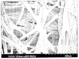
FIG. 1 is a SEM photograph showing a capacitor electrode (A) of the present invention when a cation exchanger of a sulfonic acid group is formed on a base polymer layer of comparative example 1;
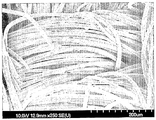
FIG. 2 is a SEM photograph showing a capacitor electrode (B) of the present invention when a cation exchanger is not formed on the base polymer layer of comparative example 1;
FIG. 3 is a unit cell structure diagram of ECDI using the capacitor electrode of the present invention;
FIG. 4 is a unit cell structure diagram of CDI;
FIG. 5 is a unit cell structure diagram of MCDI;
FIG. 6 is a graph showing comparison of conductivities in the ECDI, CDI, and MCDI processes; and
FIG. 7 is a graph showing comparison of current values in the ECDI, CDI, and MCDI processes.
The present invention describes a fabrication method for a capacitor electrode. The fabrication method for the capacitor electrode comprises: forming a base polymer layer on an upper surface of the electrode; forming a cation exchanger or an anion exchanger on the base polymer layer; and drying the electrode, wherein the base polymer layer is formed by any one selected from a group consisting of a doctor blade coating method, a dipping method, a flooding method, a spin coating method, a spraying method, a brushing method, and a painting method.
The electrode may include any one selected from a group consisting of carbon, a mixture of carbon and metal, a compound containing carbon and metal, a mixture of carbon and a binder, and a mixture of carbon and functional substance. The carbon, which is any one porous carbon selected from a group consisting of aerogel, activated carbon, graphite, recticulated vitreous carbon (RVC), and carbon fiber, may include carbon in the form of paper, fiber, cloth, AC composite or a felt, having conductivity. The functional substance may be an ion exchange fiber. The binder may be a binder that is commonly used.
The base polymer layer may include hydrocarbon-based polymer, fluorinated polymer or semifluorinated polymer.
The hydrocarbon-based polymer may include one or more mixture selected from a group consisting of bromomethylated poly(2,6-dimethyl-1,4-phenylene oxide) (BPPO), polystyrene, styrene butadiene, polyethylene, polypropylene, polyarylene ether, polyimide, polyetherimide, polyketone, polyetherketone, polysulfone, polyimidazole, and polybenzimidazole. Further, the hydrocarbon-based polymer may include a copolymer that is obtained by copolymerizing one or more selected from a group consisting of bromomethylated poly(2,6-dimethyl-1,4-phenylene oxide) (BPPO), polystyrene, styrene butadiene, polyethylene, polypropylene, polyarylene ether, polyimide, polyetherimide, polyketone, polyetherketone, polysulfone, polyimidazole, and polybenzimidazole.
The semifluorinated polymer may include one or more mixture selected from a group consisting of polyvinylidene fluoride (PVDF), polytetrafluoroethylene (PTFE), ethylene tetrafluoroethylene (ETFE), tetrafluoroethylene- perfluoroalkylvinyl ether copolymer (poly(perfluoroalkyl acrylate), PFA), tetrafluoroethylene-hexafluoropropylene copolymer (fluorinated ethylene propylene, FEP), and polyvinyl fluoride (PVF). In addition, the semifluorinated polymer may include a copolymer that is obtained by copolymerizing one or more selected from a group consisting of polyvinylidene fluoride (PVDF), polytetrafluoroethylene (PTFE), ethylene tetrafluoroethylene (ETFE), tetrafluoroethylene-perfluoroalkylvinyl ether copolymer (poly(perfluoroalkyl acrylate), PFA), tetrafluoroethylene-hexafluoropropylene copolymer (fluorinated ethylene propylene, FEP), and polyvinyl fluoride (PVF).
The cation exchanger may be any one of a sulfonic acid group, a phosphoric acid group, and a carboxylic acid group.
The anion exchanger may be any one of a primary amine group, a secondary amine group, a tertiary amine group, a quaternary ammonium group, a poly ethylene imine group, and a phosphonium group.
The capacitor electrode of the present invention provides advantages in view of a high ion removal rate in the water treatment process and low power consumption, etc. Further, the capacitor electrode of the present invention provides advantages in view of a rapid ion capacitive ability, a low resistance loss, etc., such that it can also be applied to a super capacitor, etc.
Hereinafter, the present invention will be described in detail with reference to Examples and Comparative Examples. The present invention may, however, be embodied in many different forms and should not be construed as being limited to the Examples set forth herein.
Example 1: Fabrication of capacitor electrode having a sulfonic acid group as a cation exchanger
1g of bromomethylated poly(2,6-dimethyl-1,4-phenylene oxide)(BPPO) was put in 5ml of N-methylpyrrolidone (NMP) and then was sufficiently mixed at room temperature for 1 day, thereby making a mixed solution. The mixed solution was put into a centrifugal separator and was centrifuged at a temperature of 25℃ for 30 minutes at 13,000 rpm. The solid obtained by centrifuging the mixed solution was cleaned with distilled water four times or more and then was put in a vacuum state at a temperature of 40℃ for 12 hours or more, thereby obtaining pure BPPO.
5ml of NMP was put for each 1g of the pure BPPO obtained as above and then was sufficiently mixed at room temperature for 1 day, thereby making a BPPO solution. 0.02 to 20ml of BPPO solution was sprayed on a porous carbon electrode having a size of 0.05 to 50 cm2. Then, the porous carbon electrode to which the BPPO solution was sprayed was dried at a temperature of 40℃ for 12 hours or more. As a result, the porous carbon electrode where the BPPO is formed as a base polymer layer was fabricated.
The porous carbon electrode where the BPPO is formed as the base polymer layer was dipped in 100% sulfuric acid solution for 20 minutes and then was dipped in 80% sulfuric acid solution, 50% sulfuric acid solution, and 30% sulfuric acid solution each for 1 minute. Thereafter, the porous carbon electrode was cleaned with distilled water. As a result, a capacitor electrode where the sulfonic acid group is formed on the base polymer layer as a cation exchanger was obtained.
Example 2: Fabrication of capacitor electrode having a quaternary amine group as an anion exchanger
1g of bromomethylated poly(2,6-dimethyl-1,4-phenylene oxide)(BPPO) was put in 5ml of N-methylpyrrolidone (NMP) and then was sufficiently mixed at room temperature for 1 day, thereby making a mixed solution. The mixed solution was put into a centrifugal separator and was centrifuged at a temperature of 25℃ for 30 minutes at 13,000 rpm. The solid obtained by centrifuging the mixed solution was cleaned with distilled water four times or more and then was put in a vacuum state at a temperature of 40˚C for 12 hours or more, thereby obtaining pure BPPO.
5ml of NMP was put for each 1g of the pure BPPO obtained as above and then was sufficiently mixed at room temperature for 1 day, thereby making a BPPO solution. 0.02 to 20ml of BPPO solution was sprayed on a porous carbon electrode having a size of 0.05 to 50 cm2. Then, the porous carbon electrode to which the BPPO solution was sprayed was dried at a temperature of 40℃ for 12 hours or more. As a result, the porous carbon electrode where the BPPO is formed as a base polymer layer was fabricated.
The porous carbon electrode where the BPPO is formed as the base polymer layer was dipped in trimethylamine (TMA) solution for 20 minutes and was cleaned with distilled water. As a result, a capacitor electrode where the quaternary amine group is formed on the base polymer layer as an anion exchanger was obtained.
Comparative Example 1
A capacitor electrode (A) where a sulfonic acid group of a cation exchanger is formed on a base polymer layer was compared with a capacitor electrode (B) configured of pure carbon fiber. The capacitor electrode fabricated in Example 1 was used as the capacitor electrode (A).
The capacitor electrode (B) was fabricated through the following process.
1g of bromomethylated poly(2,6-dimethyl-1,4-phenylene oxide)(BPPO) was put in 5ml of N-methylpyrrolidone (NMP) and then was sufficiently mixed at room temperature for 1 day, thereby making a mixed solution. The mixed solution was put into a centrifugal separator and was centrifuged at a temperature of 25˚C for 30 minutes at 13,000 rpm. The solid obtained by centrifuging the mixed solution was cleaned with distilled water four times or more and then was put in a vacuum state at a temperature of 40˚C for 12 hours or more, thereby obtaining pure BPPO.
5ml of NMP was put for each 1g of the pure BPPO obtained as above and then was sufficiently mixed at room temperature for 1 day, thereby making a BPPO solution. 0.02 to 20ml of BPPO solution was sprayed to a porous carbon electrode having a size of 0.05 to 50 cm2. Then, the porous carbon electrode to which the BPPO solution was sprayed was dried at a temperature of 40℃ for 12 hours or more. As a result, the porous carbon electrode (B) where the BPPO is formed as a base polymer layer was fabricated.
The SEM photographs of the capacitor electrode (A) of the present invention and the capacitor electrode (B) as described above are shown in FIGS. 1 and 2, respectively. Differently from the capacitor electrode (B), a gap between the respective electrodes was filled with the cation exchanger of the sulfonic acid in the capacitor electrode (A). As a result, the capacitor electrode (A) reduces a contact resistance, thereby increasing conductivity.
Comparative Example 2
As a water treatment process of removing ions using a capacitor electrode where a cation exchanger is formed on a base polymer layer of the present invention and a capacitor electrode where an anion exchanger is formed on the base polymer layer thereof, a unit cell structure diagram of embedded capacitive deionization (ECDI) is shown in FIG. 3. A current collection plate is coupled to the lower surface of the capacitor electrode.
Compared therewith, as a water treatment process of removing ions using the capacitor electrode coupled to the current collection plate, a unit cell structure diagram of capacitive deionization (CDI) process is shown in FIG. 4.
Further, as a water treatment process of removing ions using a capacitor electrode where a cation exchange membrane is formed and a capacitor electrode where an anion exchange membrane is formed, a unit cell structure diagram of membrane capacitive deionization (MCDI) is shown in FIG. 5. A current collection plate is coupled to the lower surface of the capacitor electrode.
Comparative Example 3: Ion removal rate
As shown in Comparative Example 2, in order to check ion removal performance when the capacitor electrode of the present invention is used in the ECDI process (see FIG. 3), conductivity while the process is performed was reviewed. The process under the operation conditions of voltage of 1.8V and flow rate of 4ml/min was performed for 30 minutes.
As the comparative example of the ECDI process, as shown in Comparative Example 2, conductivities when the capacitor electrode configured of pure carbon fiber is used in the CDI process (see FIG. 4) and when the capacitor electrode where the ion exchange membrane is formed is used in the MCDI process (see FIG. 5) were reviewed.
FIG. 6 is a graph showing comparison of conductivities in the ECDI, CDI, and MCDI processes.
In the case of the ECDI process of the present invention, the conductivity fell from 188.9μS/cm to 31.5μS/cm. From the change in the conductivity, it could be appreciated that the ion removal rate in the ECDI process was as high as 83.4%. Ions were selectively absorbed due to the action of the ion exchanger of the capacitor electrode used in the ECDI process, such that the ions were efficiently removed.
In the case of the CDI process, the conductivity fell from 190.8μS/cm to 39.9μS/cm. From the change in the conductivity, the ion removal rate in the CDI process was calculated as 79.1%.
In the case of the MCDI process, the conductivity fell from 185.1μS/cm to 168μS/cm. From the change in the conductivity, the ion removal rate in the MCDI process was calculated as 9.23%. With the voltage under the same condition as the ECDI process of the present invention, the ion removal rate in the MCDI process was significantly lower.
Comparative Example 4: Power consumption
As shown in Comparative Example 2, in order to check power consumption when the capacitor electrode of the present invention is used in the ECDI process (see FIG. 3), current values while the process is performed were examined. The process under the operation conditions of voltage of 1.8V and flow rate of 4ml/min was performed for 30 minutes.
As the comparative example of the ECDI process, as shown in Comparative Example 2, current values when the capacitor electrode without ion exchanger on the base polymer layer is used in the CDI process (see FIG. 4) and when the capacitor electrode where the ion exchanger is formed on the base polymer layer is used in the MCDI process (see FIG. 5) were compared.
FIG. 7 is a graph showing comparison of current values in the ECDI, CDI, and MCDI processes.
The average value of current while the ECDI process of the present invention is performed for 30 minutes was as low as 0.02564A. As a result, the power consumption calculated using the average value of current was merely 0.02308Wh (0.02564A x 1.8V x 0.5 = 0.02308Wh).
The average value of current while the CDI process of the present invention is performed for 30 minutes was 0.2357A. The power consumption calculated using the average value of current was 0.2121Wh (0.2357A x 1.8V x 0.5 = 0.2121Wh).
The average value of current while the MCDI process of the present invention is performed for 30 minutes was 0.002575A. The power consumption calculated using the average value of current was 0.002318Wh (0.002575A x 1.8V x 0.5 = 0.002318Wh). Although the power consumption in the MCDI process was very low, the ion removal rate at this time was merely 9.23% (see Comparative Example 3). Therefore, the object of the MCDI process, removal of dissolved ions, can not be accomplished.
Through the results of Comparative Example 3 and Comparative Example 4, it can be confirmed that it is the most preferable to perform the water treatment using the ECDI process using the capacitor electrode of the present invention. In other words, when performing the water treatment using the capacitor electrode of the present invention, the ion removal rate can be enhanced and at the same time, the power consumption can also be significantly reduced compared to the CDI process.
While the present invention has been described with reference to the preferred embodiments, it will be understood by those skilled in the related art that various modifications and variations may be made therein without departing from the scope of the present invention as defined by the appended claims.
Claims (10)
- A fabrication method for a capacitor electrode comprising:forming a base polymer layer on an upper surface of the electrode;forming a cation exchanger or an anion exchanger on the base polymer layer; anddrying the electrode,wherein, the base polymer layer is formed by any one selected from a group consisting of a doctor blade coating method, a dipping method, a flooding method, a spin coating method, a spraying method, a brushing method, and a painting method.
- The fabrication method according to claim 1, wherein the electrode includes any one selected from a group consisting of carbon, a mixture of carbon and metal, a compound containing carbon and metal, a mixture of carbon and a binder, a mixture of carbon and functional substance, and the carbon is any one conductive porous carbon selected from a group consisting of aerogel, activated carbon, graphite, recticulated vitreous carbon (RVC), and carbon fiber.
- The fabrication method according to claim 2, wherein the functional substance is ion exchange fiber.
- The fabrication method according to claim 1, wherein the base polymer layer includes any one of hydrocarbon-based polymer, fluorinated polymer, and semifluorinated polymer.
- The fabrication method according to claim 4, wherein the hydrocarbon-based polymer includes one or more mixture selected from a group consisting of bromomethylated poly(2,6-dimethyl-1,4-phenylene oxide) (BPPO), polystyrene, styrene butadiene, polyethylene, polypropylene, polyarylene ether, polyimide, polyetherimide, polyketone, polyetherketone, polysulfone, polyimidazole, and polybenzimidazole.
- The fabrication method according to claim 4, wherein the hydrocarbon-based polymer includes a copolymer that is obtained by copolymerizing one or more selected from a group consisting of bromomethylated poly(2,6-dimethyl-1,4-phenylene oxide) (BPPO), polystyrene, styrene butadiene, polyethylene, polypropylene, polyarylene ether, polyimide, polyetherimide, polyketone, polyetherketone, polysulfone, polyimidazole, and polybenzimidazole.
- The fabrication method according to claim 4, wherein the semifluorinated polymer includes one or more mixture selected from a group consisting of polyvinylidene fluoride (PVDF), polytetrafluoroethylene (PTFE), ethylene tetrafluoroethylene (ETFE), tetrafluoroethylene-perfluoroalkylvinyl ether copolymer (poly(perfluoroalkyl acrylate), PFA), tetrafluoroethylene-hexafluoropropylene copolymer (fluorinated ethylene propylene, FEP), and polyvinyl fluoride (PVF).
- The fabrication method according to claim 4, wherein the semifluorinated polymer includes a copolymer that is obtained by copolymerizing one or more selected from a group consisting of polyvinylidene fluoride (PVDF), polytetrafluoroethylene (PTFE), ethylene tetrafluoroethylene (ETFE), tetrafluoroethylene-perfluoroalkylvinyl ether copolymer (poly(perfluoroalkyl acrylate), PFA), tetrafluoroethylene-hexafluoropropylene copolymer (fluorinated ethylene propylene, FEP), and polyvinyl fluoride (PVF).
- The fabrication method according to claim 1, wherein the cation exchanger is any one of a sulfonic acid group, a phosphoric acid group, and a carboxylic acid group.
- The fabrication method according to claim 1, wherein the anion exchanger is any one of a primary amine group, a secondary amine group, a tertiary amine group, a quaternary ammonium group, a poly ethylene imine group, and a phosphonium group.
Applications Claiming Priority (2)
| Application Number | Priority Date | Filing Date | Title |
|---|---|---|---|
| KR10-2009-0018599 | 2009-03-04 | ||
| KR1020090018599A KR101374729B1 (en) | 2009-03-04 | 2009-03-04 | Fabrication Method For Capacitor Electrode |
Publications (1)
| Publication Number | Publication Date |
|---|---|
| WO2010101338A1 true WO2010101338A1 (en) | 2010-09-10 |
Family
ID=42709865
Family Applications (1)
| Application Number | Title | Priority Date | Filing Date |
|---|---|---|---|
| PCT/KR2009/004261 Ceased WO2010101338A1 (en) | 2009-03-04 | 2009-07-30 | Fabrication method for capacitor electrode |
Country Status (2)
| Country | Link |
|---|---|
| KR (1) | KR101374729B1 (en) |
| WO (1) | WO2010101338A1 (en) |
Cited By (4)
| Publication number | Priority date | Publication date | Assignee | Title |
|---|---|---|---|---|
| EP2896600A4 (en) * | 2012-09-13 | 2016-04-20 | Kuraray Co | ELECTRODE, PROCESS FOR PRODUCING THE SAME, AND CONTINUOUS FLOW CAPACITOR COMPRISING SAME |
| CN116504543A (en) * | 2023-05-10 | 2023-07-28 | 苏州大学 | Symmetrical flexible supercapacitor and preparation method thereof |
| CN117466392A (en) * | 2023-11-21 | 2024-01-30 | 华南理工大学 | An ion selective adsorption electrode, micro-electric field adsorption system and its application in water softening and sterilization and algae removal |
| CN117466392B (en) * | 2023-11-21 | 2026-05-05 | 华南理工大学 | Ion selective adsorption electrode, micro-electric field adsorption system and application thereof in water softening, sterilization and algae removal |
Families Citing this family (1)
| Publication number | Priority date | Publication date | Assignee | Title |
|---|---|---|---|---|
| KR101254653B1 (en) * | 2011-01-24 | 2013-04-15 | (주) 시온텍 | Method for preparing carbon electrode coated an anion exchanging polymer |
Citations (4)
| Publication number | Priority date | Publication date | Assignee | Title |
|---|---|---|---|---|
| US6426863B1 (en) * | 1999-11-25 | 2002-07-30 | Lithium Power Technologies, Inc. | Electrochemical capacitor |
| US20020167782A1 (en) * | 2001-04-18 | 2002-11-14 | Andelman Marc D. | Charge barrier flow-through capacitor |
| US20080078672A1 (en) * | 2006-09-29 | 2008-04-03 | Atlas Robert D | Hybrid Capacitive Deionization and Electro-Deionization (CDI-EDI) Electrochemical Cell for Fluid Purification |
| US20080198531A1 (en) * | 2007-02-15 | 2008-08-21 | Lih-Ren Shiue | Capacitive deionization system for water treatment |
Family Cites Families (1)
| Publication number | Priority date | Publication date | Assignee | Title |
|---|---|---|---|---|
| KR100568309B1 (en) * | 2004-09-01 | 2006-04-05 | 삼성전기주식회사 | A method of manufacturing a polymer capacitor using fine pore formation in an ion exchange membrane and a polymer capacitor |
-
2009
- 2009-03-04 KR KR1020090018599A patent/KR101374729B1/en not_active Expired - Fee Related
- 2009-07-30 WO PCT/KR2009/004261 patent/WO2010101338A1/en not_active Ceased
Patent Citations (4)
| Publication number | Priority date | Publication date | Assignee | Title |
|---|---|---|---|---|
| US6426863B1 (en) * | 1999-11-25 | 2002-07-30 | Lithium Power Technologies, Inc. | Electrochemical capacitor |
| US20020167782A1 (en) * | 2001-04-18 | 2002-11-14 | Andelman Marc D. | Charge barrier flow-through capacitor |
| US20080078672A1 (en) * | 2006-09-29 | 2008-04-03 | Atlas Robert D | Hybrid Capacitive Deionization and Electro-Deionization (CDI-EDI) Electrochemical Cell for Fluid Purification |
| US20080198531A1 (en) * | 2007-02-15 | 2008-08-21 | Lih-Ren Shiue | Capacitive deionization system for water treatment |
Cited By (5)
| Publication number | Priority date | Publication date | Assignee | Title |
|---|---|---|---|---|
| EP2896600A4 (en) * | 2012-09-13 | 2016-04-20 | Kuraray Co | ELECTRODE, PROCESS FOR PRODUCING THE SAME, AND CONTINUOUS FLOW CAPACITOR COMPRISING SAME |
| CN116504543A (en) * | 2023-05-10 | 2023-07-28 | 苏州大学 | Symmetrical flexible supercapacitor and preparation method thereof |
| CN117466392A (en) * | 2023-11-21 | 2024-01-30 | 华南理工大学 | An ion selective adsorption electrode, micro-electric field adsorption system and its application in water softening and sterilization and algae removal |
| WO2025107807A1 (en) * | 2023-11-21 | 2025-05-30 | 华南理工大学 | Electrode capable of selectively adsorbing ions, and micro-electric field adsorption system and use thereof in water softening, sterilization and algae removal |
| CN117466392B (en) * | 2023-11-21 | 2026-05-05 | 华南理工大学 | Ion selective adsorption electrode, micro-electric field adsorption system and application thereof in water softening, sterilization and algae removal |
Also Published As
| Publication number | Publication date |
|---|---|
| KR101374729B1 (en) | 2014-03-17 |
| KR20100099980A (en) | 2010-09-15 |
Similar Documents
| Publication | Publication Date | Title |
|---|---|---|
| KR102189857B1 (en) | A highly ion-selective composite polymer electrolyte membranes comprising a metal-ion blocking layer, redox flow batteries comprising the same, and electrochemical devices comprising the same | |
| JP5524330B2 (en) | Polymer composite electrolyte, battery containing polymer composite electrolyte, and method for preparing the same | |
| CN102002168B (en) | Ion exchange membrane having lamellar morphology and process of making the same | |
| JP5415518B2 (en) | Fuel cell with hydrophobic diffusion medium | |
| KR102140121B1 (en) | Reinforced-Composite Electrolyte Membrane Comprising Porous Polymer Substrate And Manufacturing Method Thereof | |
| CN107994244B (en) | Preparation, membrane and application of a multi-layer composite proton exchange membrane | |
| WO2011025259A2 (en) | Polymer electrolyte membrane for a fuel cell, and method for preparing same | |
| WO2020111687A1 (en) | Separator for redox flow battery and manufacturing method therefor | |
| WO2011016662A2 (en) | Capacitive electrode for deionization, and electrolytic cell using same | |
| CN103682212B (en) | Application of an Alkaline Porous Membrane in Flow Energy Storage Batteries | |
| WO2010101338A1 (en) | Fabrication method for capacitor electrode | |
| WO2012153915A2 (en) | Method for manufacturing a membrane-electrode assembly for a polymer electrolyte, and membrane-electrode assembly manufactured thereby | |
| WO2019004712A1 (en) | Electrolyte membrane for fuel cell, comprising spun nanofiber layer | |
| CN106848150B (en) | Preparation method of modified diaphragm for lithium battery | |
| WO2014148841A1 (en) | Separation membrane for electrochemical device and manufacturing method therefor | |
| CN106589443A (en) | Sulfonated graphene modified perfluorinated sulfonic acid ion composite membrane and preparation method thereof | |
| WO2015065121A1 (en) | Porous separation membrane for electrochemical device, containing porous substrate having inverse opal structure, and preparation method therefor | |
| CN113346191B (en) | Asymmetric diaphragm containing conductive layer, preparation method and application thereof | |
| KR102822239B1 (en) | Coated Battery Separator | |
| WO2019139320A1 (en) | Method for manufacturing reinforced separator, reinforced separator manufactured thereby, and redox flow battery | |
| CN111484105A (en) | Capacitive deionization electrode, preparation method thereof and capacitive deionization device | |
| CN115465925A (en) | A kind of polyvinyl alcohol-based gel composite membrane electrode and preparation method thereof | |
| WO2012128460A2 (en) | Separator film coating material using a polymer derived from mussels and method for manufacturing same, and material for preventing heat shrinkage and method for manufacturing same | |
| WO2022071684A1 (en) | Polymer electrolyte membrane, membrane-electrode assembly comprising same, and fuel cell | |
| JP2021153048A (en) | Electrolyte membrane for redox flow battery and redox flow battery |
Legal Events
| Date | Code | Title | Description |
|---|---|---|---|
| 121 | Ep: the epo has been informed by wipo that ep was designated in this application |
Ref document number: 09841200 Country of ref document: EP Kind code of ref document: A1 |
|
| NENP | Non-entry into the national phase |
Ref country code: DE |
|
| 122 | Ep: pct application non-entry in european phase |
Ref document number: 09841200 Country of ref document: EP Kind code of ref document: A1 |