WO2010087641A2 - System and method for uplink data and control signal transmission in mimo wireless systems - Google Patents
System and method for uplink data and control signal transmission in mimo wireless systems Download PDFInfo
- Publication number
- WO2010087641A2 WO2010087641A2 PCT/KR2010/000545 KR2010000545W WO2010087641A2 WO 2010087641 A2 WO2010087641 A2 WO 2010087641A2 KR 2010000545 W KR2010000545 W KR 2010000545W WO 2010087641 A2 WO2010087641 A2 WO 2010087641A2
- Authority
- WO
- WIPO (PCT)
- Prior art keywords
- layer
- layers
- control information
- data
- uplink control
- Prior art date
Links
- 238000000034 method Methods 0.000 title claims description 37
- 230000008054 signal transmission Effects 0.000 title description 4
- 230000005540 biological transmission Effects 0.000 claims abstract description 76
- 238000013507 mapping Methods 0.000 claims abstract description 30
- 238000004891 communication Methods 0.000 claims description 14
- 101000741965 Homo sapiens Inactive tyrosine-protein kinase PRAG1 Proteins 0.000 claims description 12
- 102100038659 Inactive tyrosine-protein kinase PRAG1 Human genes 0.000 claims description 12
- 230000003595 spectral effect Effects 0.000 claims description 9
- 239000000969 carrier Substances 0.000 claims description 8
- 230000011664 signaling Effects 0.000 claims 2
- 108091006146 Channels Proteins 0.000 description 58
- 238000012545 processing Methods 0.000 description 15
- 239000011159 matrix material Substances 0.000 description 7
- 230000006870 function Effects 0.000 description 6
- 230000008569 process Effects 0.000 description 5
- 230000011218 segmentation Effects 0.000 description 5
- 239000013598 vector Substances 0.000 description 5
- 239000000945 filler Substances 0.000 description 2
- 238000012986 modification Methods 0.000 description 2
- 230000004048 modification Effects 0.000 description 2
- 238000003908 quality control method Methods 0.000 description 2
- 238000013468 resource allocation Methods 0.000 description 2
- 102100039819 Actin, alpha cardiac muscle 1 Human genes 0.000 description 1
- 239000004243 E-number Substances 0.000 description 1
- 101000959247 Homo sapiens Actin, alpha cardiac muscle 1 Proteins 0.000 description 1
- 101100465000 Mus musculus Prag1 gene Proteins 0.000 description 1
- 230000002776 aggregation Effects 0.000 description 1
- 238000004220 aggregation Methods 0.000 description 1
- 238000013459 approach Methods 0.000 description 1
- 238000004364 calculation method Methods 0.000 description 1
- 125000004122 cyclic group Chemical group 0.000 description 1
- 230000001419 dependent effect Effects 0.000 description 1
- 238000001514 detection method Methods 0.000 description 1
- 238000010586 diagram Methods 0.000 description 1
- 230000000694 effects Effects 0.000 description 1
- 238000005516 engineering process Methods 0.000 description 1
- 239000000835 fiber Substances 0.000 description 1
- 238000001914 filtration Methods 0.000 description 1
- 238000003780 insertion Methods 0.000 description 1
- 230000037431 insertion Effects 0.000 description 1
- 230000002452 interceptive effect Effects 0.000 description 1
- 230000001788 irregular Effects 0.000 description 1
- 239000004973 liquid crystal related substance Substances 0.000 description 1
- 230000007774 longterm Effects 0.000 description 1
- 239000013307 optical fiber Substances 0.000 description 1
- 238000009877 rendering Methods 0.000 description 1
- SYOKIDBDQMKNDQ-XWTIBIIYSA-N vildagliptin Chemical compound C1C(O)(C2)CC(C3)CC1CC32NCC(=O)N1CCC[C@H]1C#N SYOKIDBDQMKNDQ-XWTIBIIYSA-N 0.000 description 1
Classifications
-
- H—ELECTRICITY
- H04—ELECTRIC COMMUNICATION TECHNIQUE
- H04B—TRANSMISSION
- H04B7/00—Radio transmission systems, i.e. using radiation field
- H04B7/02—Diversity systems; Multi-antenna system, i.e. transmission or reception using multiple antennas
- H04B7/04—Diversity systems; Multi-antenna system, i.e. transmission or reception using multiple antennas using two or more spaced independent antennas
- H04B7/0413—MIMO systems
-
- H—ELECTRICITY
- H04—ELECTRIC COMMUNICATION TECHNIQUE
- H04L—TRANSMISSION OF DIGITAL INFORMATION, e.g. TELEGRAPHIC COMMUNICATION
- H04L1/00—Arrangements for detecting or preventing errors in the information received
- H04L1/12—Arrangements for detecting or preventing errors in the information received by using return channel
- H04L1/16—Arrangements for detecting or preventing errors in the information received by using return channel in which the return channel carries supervisory signals, e.g. repetition request signals
- H04L1/18—Automatic repetition systems, e.g. Van Duuren systems
- H04L1/1829—Arrangements specially adapted for the receiver end
- H04L1/1861—Physical mapping arrangements
Definitions
- the present application relates generally to wireless communications networks and, more specifically, to data and control signal transmissions in a wireless communication network.
- MIMO antenna systems also known as multiple- element antenna (MEA) systems
- MIMO multiple- element antenna
- RF radio frequency
- each of a plurality of data streams is individually mapped and modulated before being precoded and transmitted by different physical antennas or effective antennas.
- the combined data streams are then received at multiple antennas of a receiver.
- each data stream is separated and extracted from the combined signal. This process is generally performed using a minimum mean squared error (MMSE) or MMSE-successive interference cancellation (SIC) algorithm.
- MMSE minimum mean squared error
- SIC MMSE-successive interference cancellation
- a mobile station capable of communicating via an uplink transmission to at least one base station in a Multiple Input Multiple Output wireless network.
- the mobile station includes a plurality of transmit antenna and a transmitter coupled to the plurality of transmit antenna.
- the transmitter includes a layer mapper that maps data and uplink control information to at least one layer. The mapping is performed prior to Discrete Fourier Transform precoding such that the data and uplink control information are multiplexed and interleaved.
- the transmitter is configured to simultaneously transmit the data and uplink control information on at least one of a plurality of transmission layers.
- the apparatus includes a Discrete Fourier Transform (DFT) precoder; and a layer mapper.
- the layer mapper is configured to map data and uplink control information to at least one layer. The mapping is performed prior to DFT precoding by the DFT precoder such that the data and uplink control information are multiplexed and interleaved.
- the apparatus is configured to simultaneously transmit the data and uplink control information on at least one of a plurality of transmission layers.
- a method for communicating uplink control information via an uplink transmission in a Multiple Input Multiple Output wireless network includes mapping data and uplink control information to at least one layer. The mapping is performed prior to DFT precoding such that the data and uplink control information are multiplexed and interleaved. The method also includes simultaneously transmitting the data and uplink control information on at least one of a plurality of transmission layers.
- the decoding performance of the receiver is improved as compared to a receiver that decodes streams in a random or pre-determined order without being as complex as a receiver that searches all possible decoding orders to find the optimum order.
- FIGURE 1 illustrates an Orthogonal Frequency Division Multiple Access (OFDMA) wireless network that is capable of decoding data streams according to one embodiment of the present disclosure
- OFDMA Orthogonal Frequency Division Multiple Access
- FIGURE 2 illustrates an exemplary wireless mobile station according to embodiments of the present disclosure
- FIGURE 3 illustrates a physical uplink shared channel transmission chain according to embodiments of the present disclosure
- FIGURE 4 illustrates a graph of data and control multiplexing in an LTE system according to embodiments of the disclosure
- FIGURE 5 illustrates transport channel processing for an uplink shared channel according to embodiments of the present disclosure
- FIGURE 6 illustrates an uplink transmission chain for Nt transmit antenna for N layer transmissions according to embodiments of the present disclosure.
- FIGURES 7-10 illustrate graphs for transmitting data and control information according to embodiments of the present disclosure. [Mode for Invention]
- FIGURES 1 through 10 discussed below, and the various embodiments used to describe the principles of the present disclosure in this patent document are by way of illustration only and should not be construed in any way to limit the scope of the disclosure. Those skilled in the art will understand that the principles of the present disclosure may be implemented in any suitably arranged wireless Communications network.
- LTE Long Term Evolution
- node B is another term for “base station” used below.
- LTE term “user equipment” or “UE” is another term for “subscriber station” (or “SS”) used below.
- FIGURE 1 illustrates exemplary wireless network 100 that is capable of decoding data streams according to one embodiment of the present disclosure.
- wireless network 100 includes base station (BS) 101 , base station (BS) 102, and base station (BS) 103.
- Base station 101 communicates with base station 102 and base station 103.
- Base station 101 also communicates with Internet protocol (IP) network 130, such as the Internet, a proprietary IP network, or other data network.
- IP Internet protocol
- Base station 102 provides wireless broadband access to network 130, via base station 101 , to a first plurality of subscriber stations within coverage area 120 of base station 102.
- the first plurality of subscriber stations includes subscriber station (SS) 111 , subscriber station (SS) 112, subscriber station (SS) 113, subscriber station (SS) 114, subscriber station (SS) 115 and subscriber station (SS) 116.
- Subscriber station (SS) may be any wireless communication device, such as, but not limited to, a mobile phone, mobile PDA and any mobile station (MS).
- SS 111 may be located in a small business (SB), SS 112 may be located in an enterprise (E), SS 113 may be located in a WiFi hotspot (HS), SS 114 may be located in a first residence, SS 115 may be located in a second residence, and SS 116 may be a mobile (M) device.
- SB small business
- E enterprise
- HS WiFi hotspot
- SS 114 may be located in a first residence
- SS 115 may be located in a second residence
- SS 116 may be a mobile (M) device.
- Base station 103 provides wireless broadband access to network 130, via base station 101 , to a second plurality of subscriber stations within coverage area 125 of base station 103.
- the second plurality of subscriber stations includes subscriber station 115 and subscriber station 116.
- base stations 102 and 103 may be connected directly to the Internet by means of a wired broadband connection, such as an optical fiber, DSL, cable or T1/E1 line, rather than indirectly through base station 101.
- base station 101 may be in communication with either fewer or more base stations.
- wireless network 100 may provide wireless broadband access to more than six subscriber stations.
- subscriber station 115 and subscriber station 116 are on the edge of both coverage area 120 and coverage area 125. Subscriber station 115 and subscriber station 116 each communicate with both base station 102 and base station 103 and may be said to be operating in handoff mode, as known to those of skill in the art.
- base stations 101-103 may communicate with each other and with subscriber stations 111-116 using an IEEE-802.16 wireless metropolitan area network standard, such as, for example, an IEEE-802.16e standard. In another embodiment, however, a different wireless protocol may be employed, such as, for example, a HIPERMAN wireless metropolitan area network standard.
- Base station 101 may communicate through direct line-of-sight or non- line-of-sight with base station 102 and base station 103, depending on the technology used for the wireless backhaul.
- Base station 102 and base station 103 may each communicate through non-line-of-sight with subscriber stations 111-116 using OFDM and/or OFDMA techniques.
- Base station 102 may provide a T1 level service to subscriber station 112 associated with the enterprise and a fractional T1 level service to subscriber station 111 associated with the small business.
- Base station 102 may provide wireless backhaul for subscriber station 113 associated with the WiFi hotspot, which may be located in an airport, cafe, hotel, or college campus.
- Base station 102 may provide digital subscriber line (DSL) level service to subscriber stations 114, 115 and 116.
- DSL digital subscriber line
- Subscriber stations 111-116 may use the broadband access to network 130 to access voice, data, video, video teleconferencing, and/or other broadband services.
- one or more of subscriber stations 111-116 may be associated with an access point (AP) of a WiFi WLAN.
- Subscriber station 116 may be any of a number of mobile devices, including a wireless-enabled laptop computer, personal data assistant, notebook, handheld device, or other wireless- enabled device.
- Subscriber stations 114 and 115 may be, for example, a wireless- enabled personal computer, a laptop computer, a gateway, or another device.
- Dotted lines show the approximate extents of coverage areas 120 and 125, which are shown as approximately circular for the purposes of illustration and explanation only. It should be clearly understood that the coverage areas associated with base stations, for example, coverage areas 120 and 125, may have other shapes, including irregular shapes, depending upon the configuration of the base stations and variations in the radio environment associated with natural and man-made obstructions. Also, the coverage areas associated with base stations are not constant over time and may be dynamic (expanding or contracting or changing shape) based on changing transmission power levels of the base station and/or the subscriber stations, weather conditions, and other factors. In an embodiment, the radius of the coverage areas of the base stations, for example, coverage areas 120 and 125 of base stations 102 and 103 may extend in the range from less than 2 kilometers to about fifty kilometers from the base stations.
- a base station such as base station 101 , 102, or 103, may employ directional antennas to support a plurality of sectors within the coverage area.
- base stations 102 and 103 are depicted approximately in the center of coverage areas 120 and 125, respectively.
- the use of directional antennas may locate the base station near the edge of the coverage area, for example, at the point of a cone-shaped or pear- shaped coverage area.
- the connection to network 130 from base station 101 may comprise a broadband connection, for example, a fiber optic line, to servers located in a central office or another operating company point-of-presence.
- the servers may provide communication to an Internet gateway for internet protocol-based communications and to a public switched telephone network gateway for voice-based communications.
- voice-based communications in the form of voice- over-IP (VoIP)
- VoIP voice- over-IP
- the traffic may be forwarded directly to the Internet gateway instead of the PSTN gateway.
- the servers, Internet gateway, and public switched telephone network gateway are not shown in FIGURE 1.
- the connection to network 130 may be provided by different network nodes and equipment.
- one or more of base stations 101-103 and/or one or more of subscriber stations 111-116 comprises a receiver that is operable to decode a plurality of data streams received as a combined data stream from a plurality of transmit antennas using an MMSE-SIC algorithm.
- the receiver is operable to determine a decoding order for the data streams based on a decoding prediction metric for each data stream that is calculated based on a strength-related characteristic of the data stream.
- the receiver is able to decode the strongest data stream first, followed by the next strongest data stream, and so on.
- the decoding performance of the receiver is improved as compared to a receiver that decodes streams in a random or pre-determined order without being as complex as a receiver that searches all possible decoding orders to find the optimum order.
- FIGURE 2 illustrates an exemplary wireless subscriber station according to embodiments of the present disclosure.
- the embodiment of wireless subscriber station 116 illustrated in FIGURE 2 is for illustration only. Other embodiments of the wireless subscriber station 116 could be used without departing from the scope of this disclosure.
- Wireless subscriber station 116 comprises antenna 205, radio frequency (RF) transceiver 210, transmit (TX) processing circuitry 215, microphone 220, and receive (RX) processing circuitry 225.
- SS 116 also comprises speaker 230, main processor 240, input/output (I/O) interface (IF) 245, keypad 250, display 255, and memory 260.
- Memory 260 further comprises basic operating system (OS) program 261.
- OS basic operating system
- Radio frequency (RF) transceiver 210 receives from antenna 205 an incoming RF signal transmitted by a base station of wireless network 100.
- Antenna 205 can comprise a number (Nt) of antenna 205 (e.g., SS 116 includes Nt antenna 205).
- Radio frequency (RF) transceiver 210 down-converts the incoming RF signal to produce an intermediate frequency (IF) or a baseband signal.
- the IF or baseband signal is sent to receiver (RX) processing circuitry 225 that produces a processed baseband signal by filtering, decoding, and/or digitizing the baseband or IF signal.
- Receiver (RX) processing circuitry 225 transmits the processed baseband signal to speaker 230 (i.e., voice data) or to main processor 240 for further processing (e.g., web browsing).
- Transmitter (TX) processing circuitry 215 receives analog or digital voice data from microphone 220 or other outgoing baseband data (e.g., web data, e-mail, interactive video game data) from main processor 240. Transmitter (TX) processing circuitry 215 encodes, multiplexes, and/or digitizes the outgoing baseband data to produce a processed baseband or IF signal. Radio frequency (RF) transceiver 210 receives the outgoing processed baseband or IF signal from transmitter (TX) processing circuitry 215. Radio frequency (RF) transceiver 210 up-converts the baseband or IF signal to a radio frequency (RF) signal that is transmitted via antenna 205.
- RF radio frequency
- main processor 240 is a microprocessor or microcontroller.
- Memory 260 is coupled to main processor 240.
- part of memory 260 comprises a random access memory (RAM) and another part of memory 260 comprises a Flash memory, which acts as a read-only memory (ROM).
- RAM random access memory
- ROM read-only memory
- Main processor 340 executes basic operating system (OS) program 261 stored in the memory 260 in order to control the overall operation of wireless subscriber station 116.
- OS basic operating system
- main processor 240 controls the reception of forward channel signals and the transmission of reverse channel signals by radio frequency (RF) transceiver 210, receiver (RX) processing circuitry 225, and transmitter (TX) processing circuitry 215, in accordance with well-known principles.
- RF radio frequency
- RX receiver
- TX transmitter
- Main processor 240 is capable of executing other processes and programs resident in memory 260. Main processor 240 can move data into or out of memory 260, as required by an executing process. Main processor 240 is also coupled to I/O interface 245. I/O interface 245 provides subscriber station 116 with the ability to connect to other devices such as laptop computers and handheld computers. I/O interface 245 is the communication path between these accessories and main controller 240.
- Main processor 240 is also coupled to keypad 250 and display unit 255.
- the operator of subscriber station 116 uses keypad 250 to enter data into subscriber station 116.
- Display 255 may be a liquid crystal display capable of rendering text and/or at least limited graphics from web sites. Alternate embodiments may use other types of displays.
- FIGURE 3 illustrates a Physical Uplink Shared Channel (PUSCH) transmission chain according to embodiments of the present disclosure.
- the embodiment of the PUSCH transmission chain 270 shown in FIGURE 3 is for illustration only. Other embodiments could be used without departing from the scope of this disclosure.
- the PUSCH transmission chain 270 is used for a single-carrier frequency division multiple access (SC-FDMA) Uplink (UL) transmission of data channel PUSCH.
- the PUSCH transmission chain 270 can comprise components or functions of one or more of antenna 205, RF Transceiver 210, RX Processing Circuitry 225, TX Processing circuitry 215, processor 240 and memory 260.
- the PUSCH transmission chain 270 includes a DFT precoder 275 (also referred herein as "DFT precoding block” 275) and an Inverse Fast Fourier Transform (IFFT) block 280.
- DFT precoder 275 also referred herein as "DFT precoding block” 275
- IFFT Inverse Fast Fourier Transform
- a subcarrier mapping step 285 maps an output of the DFT precoder 275 to a contiguous set of subcarriers at the input of the IFFT 280.
- the size of IFFT 280 is greater than the size of DFT precoder 275.
- the uplink transmission includes only one layer.
- FIGURE 4 illustrates a graph of data and control multiplexing in an LTE system according to embodiments of the disclosure.
- the embodiment of the data and control multiplexing shown in FIGURE 4 is for illustration only. Other embodiments could be used without departing from the scope of this disclosure.
- the two dimensional grid 300 includes a number of data bits 305 (illustrated in the grid 300 c); a number of reference sequences 310 (illustrated in the grid 300 with an "S"); a number of Channel Quality Indices (CQI) 315 (illustrated in the grid 300 with a "Q”); a number of Acknowledgement/Negative Acknowledgement (ACK/NACK and/or A/N) bits 320 (illustrated in the grid 300 with an "A”); and a rank indicator 325 (illustrated in the grid 300 with an "R”).
- the output across all virtual subcarriers at a given OFDM symbol 330 in time is collected and sent to the DFT precoder 275.
- FIGURE 5 illustrates a diagram for transport channel processing according to embodiments of the present disclosure.
- the embodiment of the transport channel processing shown in FIGURE 5 is for illustration only. Other embodiments could be used without departing from the scope of this disclosure.
- the transport channel 400 includes an Add Cyclic Redundancy Check (CRC) block 405.
- the CRC block 405 performs error detection on Uplink-Shared Channel (UL-SCH) transport blocks through a CRC.
- UL-SCH Uplink-Shared Channel
- the entire transport block can be used to calculate the CRC parity bits.
- the bits in a transport block delivered to layer 1 are denoted by aQ, a ⁇ ,a2,SL2 '--' a A-l -
- the parity bits are denoted by
- the lowest order information bit a 0 can be mapped to the most significant bit of the transport block.
- the parity bits can be computed and attached to the UL-SCH transport block wherein L is set to 24 bits and using the generator polynomial g CRC24A (D).
- the transport channel 400 also includes a Code block segmentation, and code block CRC attachment 410.
- the bits input to the code block segmentation 410 are denoted by bo , bi , b2 , b3 ,..., bB_i where ⁇ is the number of bits in the transport block (including CRC).
- Code block segmentation and code block CRC attachment 410 are performed according to subclause 5.1.2 in 3GPP TS 36.212 v 8.5.0, "E-UTRA, Multiplexing and Channel coding", Dec 2008, the contents of which are incorporated by reference in its entirety.
- the bits after code block segmentation are denoted by c r o,c r i ,c r 2 ,c r 3 ,...,c r ( ⁇ r -i). where r is the code block number
- Kr is the number of bits for code block number r.
- the transport channel 400 also includes a channel coding block 415 for coding of data and control information.
- Code blocks from the Code block segmentation and code block CRC attachment 410, are delivered to the channel coding block 415.
- the bits in a code block are denoted by c r0' c rl> c r2> c r3 V 5 C ⁇ (K -l).
- r is the code block number
- K r is the number of bits in code block number r.
- the total number of code blocks is denoted by C and each code block can be individually turbo encoded.
- the encoded bits output from the channel coding block 415 are denoted by
- the transport channel 400 further includes a Rate matching block 420.
- Turbo coded blocks from the channel coding block 415, are delivered to the rate matching block 420.
- the Turbo coded blocks Turbo coded blocks are denoted by
- the bits output from the rate matching block 415 are denoted by e r0> e rl > e r2 > e r3 v 5 e r (E r -i), where r is the coded block number, and where E r is the number of rate matched bits for code block number r.
- the transport channel 400 further includes a Code block concatenation block 425.
- Code block concatenation is performed according to subclause 5.1.5 in 3GPP TS 36.212 v 8.5.0, "E-UTRA, Multiplexing and Channel coding", Dec 2008.
- the bits output from code block concatenation 425 are denoted by fo,fi ,f2,f3,—,fG-i . where G is the total number of coded bits for transmission excluding the bits used for control transmission, when control information is multiplexed with the UL-SCH transmission.
- the transport channel 400 includes a number of channel coding units 430a-430n.
- Control data arrives at the coding units 430a-430n in the form of channel quality information (CQI and/or PMI), Hybrid Automatic Repeat Request- Acknowledgement (HARQ-ACK) and rank indication. Different coding rates for the control information can be achieved by allocating different number of coded symbols for its transmission.
- the channel coding 430a-430n for HARQ-ACK, rank indication and channel quality information °0' o l » °2 v"> ⁇ o_i is performed independently.
- TDD Time Division Duplex
- two ACK/NACK feedback modes are supported by higher layer configuration:
- the HARQ-ACK For TDD ACK/NACK bundling, the HARQ-ACK consists of one or two bits of information.
- the HARQ-ACK For TDD ACK/NAK multiplexing, the HARQ-ACK consists of between one and four bits of information and the number of bits is determined as described in Section 7.3 in 3GPP TS 36.213 v8.5.0, "E-UTRA, Physical Layer Procedures", Dec 2008, the contents of which hereby are incorporated by reference in their entirety.
- SS 116 When SS 116 transmits HARQ-ACK bits or rank indicator bits, SS 116 can determine the number of coded symbols Q' for HARQ-ACK or rank indicator using
- Equation 1 O is the number of ACK/NACK bits or rank indicator bits, M PUSCH-current js the schedu
- N ⁇ b is the number of SC-FDMA symbols per subframe for PUSCH transmission given by - 1)- N SRS ) ,
- N ⁇ RS is equal to 1 if SS 116 is configured to send PUSCH and SRS in the same subframe or if the PUSCH resource allocation partially overlaps with the cell specific SRS subframe and bandwidth configuration defined in Section 5.5.3 of 3GPP TS 36.212 v 8.5.0, "E-UTRA, Multiplexing and Channel coding", Dec 2008. Otherwise
- N SRS is equal to 0.
- M ⁇ C USCH , N ⁇ b CH , C , and K r can be obtained from
- ⁇ offset may be determined according to 3GPP TS 36.213 v8.5.0, "E-UTRA, Physical Layer Procedures", Dec 2008.
- SS 116 when SS 116 transmits channel quality control information bits, SS 116 can determine the number of coded symbols Q' for channel quality information using Equation 2:
- Equation 2 0 is the number of CQI bits, L is the number of CRC bits
- ⁇ offset can be determined according to 3GPP TS 36.213 v8.5.0, "E-UTRA, Physical
- M ⁇ C USCH , N ⁇ H , C , and K r can be obtained from the initial
- N PUSCH-current ( 2 . ( N UL ib _ 1 j_ NsRs )
- Ns R ⁇ is equal to
- the channel coding of the channel quality information is performed according to subclause 5.2.2.6.4 of 3GPP TS 36.212 v 8.5.0, "E-UTRA, Multiplexing and Channel coding", Dec 2008, with input sequence Oo, ⁇ i, ⁇ 2,— » c>o-i -
- the CRC attachment, channel coding and rate matching of the channel quality information is performed according to subclauses 5.1.1, 5.1.3.1 and 5.1.4.2, of 3GPP TS 36.212 v 8.5.0, "E- UTRA, Multiplexing and Channel coding", Dec 2008, respectively.
- the input bit sequence to the CRC attachment is oo,oi,02,— > oo-l -
- the output bit sequence of the CRC attachment operation is the input bit sequence to the channel coding operation.
- the output bit sequence of the channel coding operation is the input bit sequence to the rate matching operation.
- the output sequence for the channel coding 430a-430n of channel quality information is denoted by qo J qi 5 q2»q3v,qQ C Q I -i -
- the transport channel 400 further includes a multiplexing of data and controls information block 435.
- the control and data multiplexing 435 can be performed such that HARQ-ACK information is present on both slots and is mapped to resources around the demodulation reference signals. Additionally, the multiplexing ensures that control and data information are mapped to different modulation symbols.
- the inputs to the data and control multiplexing 435 are the coded bits of the control information from channel coding 430a, denoted by qo,qi,q2 > q3,...,qQ COI _i and the coded bits of the UL-SCH from code block
- control multiplexing 435 operation is denoted by g Q ,g i ' where
- H is the total number of coded bits allocated for UL-SCH data and CQI/PMI information.
- control information and the data can be multiplexed as follows:
- the transport channel 400 further includes a Channel interleaver 440.
- channel interleaver 440 in conjunction with the resource element mapping for
- the inputs to the channel interleaver 440 are denoted by
- interleaver 440 can be derived as follows:
- ⁇ ⁇ mux ⁇ muX ' ⁇ m •
- the rows of the rectangular matrix are numbered 1 O', '1', '2',..., R mux - 1
- the output of the block interleaver is the bit sequence read out column by column from the (R mux x C mux ) matrix.
- the bits after channel interleaving are
- data and control information such as Channel Quality Information (CQI), Rank Information (Rl), Ack/Nack (AJN) information can be transmitted simultaneously when the MIMO scheme is used in the uplink communication.
- CQI Channel Quality Information
- Rl Rank Information
- Ack/Nack AJN
- the Uplink Control Information also referred hereinafter as "UCI" for all three types of uplink control information
- UCI can be generated for a single component carrier or multiple component carriers in the case of Carrier aggregation in systems such as LTE-advanced.
- FIGURE 6 illustrates an uplink transmission chain for Nt transmit antenna for N layer transmissions according to embodiments of the present disclosure.
- the embodiment of the uplink transmission chain 500 shown in FIGURE 6 is for illustration only. Other embodiments could be used without departing from the scope of this disclosure.
- the uplink transmission chain 500 is operable to provide a generic N layer transmission when SS 116 includes Nt transmit antenna.
- the uplink transmission chain 500 includes a Data/Control Multiplexing, interleaving layer mapping block 505 (herein after referred to as layer mapping 505).
- the layer mapping 505 is performed before DFT precoding 510, so that the data and control information are properly multiplexed and interleaved.
- the transmit precoding is performed between the DFT precoders 510a-510n and IFFTs 515a-515b to transform, on a per- subcarrier basic, an N dimension signal at the output of the DFT precoders 51 Oa- 51On to an Nt dimensional signal as an input to the group of IFFTs 515a-515b.
- the subcarrier mapping at the input of IFFTs can include non-contiguous segments of subcarriers.
- FIGURE 7 illustrates graphs for transmitting data and control information according to embodiments of the present disclosure.
- the embodiment of the graphs 600 shown in FIGURE 7 are for illustration only. Other embodiments could be used without departing from the scope of this disclosure.
- the uplink control information is carried on only one of the layers.
- the transmission may be performed using at least two (2) layers, i.e., a first layer 601 and a second layer 602.
- the first layer 601 is the first indexed layer and the second layer is the second indexed layer as defined according to the 3GPP TS 36.211 v 8.5.0, "E-UTRA, Physical channels and modulation", Dec 2008, the contents of which hereby are incorporated by reference in their entirety.
- the layer carrying the uplink control information which can be all the uplink control information including CQI, Rl and A/N bits, can be selected using a number of methods. In the following examples, N denotes the total number of transmission layers.
- the layer that has the largest MCS value is selected to carry the uplink control information such as, but not limited to, CQI, Rl and A/N.
- the MCS values typically are carried in the UL schedule assignment grant sent by BS 102 to SS 116. SS 116, therefore is aware (e.g., knows), at the time of this data and control transmission, which layer includes the largest MCS value.
- the first layer 601 has the highest MCS value; therefore, the first layer 601 is selected as the carrying layer.
- the first layer 601 carries the uplink control information such as, but not limited to, CQI, Rl and A/N.
- the control region size is defined as the number of Resource Elements (RE) transmitted within the respective region.
- the CQI 615 control region size is illustrated with the blocks with the letters "Q”, the Rl 625 size illustrated with the letters "R”, and A/N 620 size illustrated with the letters "A” and so forth.
- the first layer is chosen to carry the uplink control information such as, but not limited to, the CQI 1 Rl and A/N. This could be suitable for situations where techniques such as layer mixing/layer permutation are used to ensure the same channel quality and therefore the same MCS values on all the layers.
- the choice of layer could also be explicitly signaled in the uplink scheduling grant as an additional control field, using either DCI format O' or some other uplink grant DCI format.
- the sizes of the three control regions can be determined as a function of the corresponding Uplink Control Information (UCI) size and the MCS value associated with the first layer 601 , e.g., the layer on which the control regions are transmitted, as well as a higher layer signaled offset.
- UCI Uplink Control Information
- Equation 3 the control region equation for HARQ and Rl bits is defined by Equation 3:
- Equation 3 the inclusion of the factor "N”, which denotes the number of layers, in the numerator; and the sum in the denominator will be over all code blocks (CBs) in all layers.
- C(n) denotes the number of CBs in layer n
- K 1 denotes the size of the rth CB in layer n.
- Equation 4 [Eqn. 4]
- Equations 3 and 4 are amended to Equations 5 for Rl and A/N bits and Equation 6 for CQI bits: [Eqn. 5]
- the carrying layer can be varied or alternated.
- the first layer 601 is selected to carry the uplink control information, including the CQI 615, Rl 625 and A/N 620.
- the first layer 601 may be been randomly selected, selected as a result of the first layer 601 having the largest MCS value, or selected using some other criterion.
- the uplink control information is carried on the second layer 602.
- the uplink control information is carried on the first layer 601, and so forth.
- FIGURE 8 illustrates graphs for transmitting data and control information according to embodiments of the present disclosure.
- the embodiment of the graphs 700 shown in FIGURE 8 are for illustration only. Other embodiments could be used without departing from the scope of this disclosure.
- the uplink control information is mapped to a subset (referred to as Ns) of the N layers that are transmitted on the uplink in a MIMO uplink subframe.
- the size of the subset (Ns) can be less than or equal to the total number of layers in the uplink transmission (i.e., Ns ⁇ N).
- SS 116 can be informed, or become aware of, the layers used for uplink control transmission according to one of the following methods.
- the subset of layers (Ns) used for uplink control information can be explicitly signaled in the uplink scheduling grant as an additional control field.
- BS 102 Using either DCI format '0' or some other uplink grant DCI format, BS 102 explicitly informs SS 116 regarding the subset of layer (Ns).
- SS 116 In a second method wherein SS 116 identifies the subset (Ns) of layers that will carry the uplink control information, SS 116 implicitly infers the subset of layers (Ns). SS 116 can implicitly inform the subset of layers (Ns) according any one or more of: (1) a number of codewords; (2) codeword to layer mapping structure; and (3) a codeword that uses highest MCS value.
- SS 116 can decide to transmit uplink control information on the first layer 701 and second layer 701. SS 116 can select the first layer 701 and second layer 701 as the carrying layers since the first layer 701 and second layer 701 correspond to the layers with the better MCS.
- FIGURE 9 illustrates graphs for transmitting data and control information according to embodiments of the present disclosure.
- the embodiment of the graphs 800 shown in FIGURE 9 are for illustration only. Other embodiments could be used without departing from the scope of this disclosure.
- SS 116 can be configured to determine the uplink control regions by following one of the following rules. It is noted that the subset of layers (Ns) that contain control information also are referred herein as "active layers.”
- FIGURE 9 illustrates embodiments wherein the active layers include all the layers in the uplink transmission.
- the active layers e.g., the first layer 801 and second layer 801 carrying the uplink control information
- the total size of each control region (CQI 815, Rl 825, A/N 820) across the active layers 801 , 802 is determined as a function of the corresponding uplink control information size and this single MCS value.
- the control information can be distributed evenly across the active layers 801 , 802, where each layer receives roughly 1/Ns of the total control region size. This could be suitable for situations where techniques such as layer mixing/layer permutation are used to ensure the same channel quality and therefore the same MCS values on all the layers.
- the first layer 801 receives ⁇ A (i.e., 1/Ns) the uplink control information and the second layer 802 receives ⁇ A the uplink control information.
- the active layers e.g., the first layer 801 and second layer 801 carrying the uplink control information
- the active layers include different MCS in their transmissions
- a per-layer control region size is determined according to the UCI size and the MCS on that particular layer.
- the total size of the control region is the sum of the per-layer control region sizes over the active layers 801 , 802.
- the control information is then distributed to the active layers 801 , 802, according to the per-layer control region size.
- Equation 7 a second alternative embodiment, one example of determining the overall control region size can be given by Equations 7 and 8:
- Equation 7 Q'(n) is the number of Rl and A/N symbols in the nth active layer.
- Equation 8 Q'(n) is the number of CQI symbols in the nth active layer, and QRJ( ⁇ ) is the number of Rl symbols allocated on this active layer.
- the size of the total control region is jointly determined as a function of the UCI size and the MCSs on the active layers 801 , 802, and the control information is distributed evenly across the active layers 801, 802, where each layer (e.g., the first layer 801 and second layer 802) gets roughly 1/Ns of the total control region size.
- Equation 9 for Rl and A/N bits
- Equation 10 for CQI bits [Eqn. 9]
- the first summation on the denominator is summed over all active layers.
- filler symbols are added to assist in evenly distributing the UCI across the active layers 801 , 802. For example, using Equation 11 :
- FIGURE 10 illustrates graphs for transmitting data and control information according to embodiments of the present disclosure.
- the embodiment of the graphs 900 shown in FIGURE 10 are for illustration only. Other embodiments could be used without departing from the scope of this disclosure.
- the UCI for each component carrier is transmitted on a separate layer.
- the size of the control region for each layer 901 , 902 can be dependent on the UCI size of the corresponding CC, as well as the MCS value on this layer.
Abstract
A mobile station includes a transmission chain capable of communicating via an uplink transmission to at least one base station in a Multiple Input Multiple Output wireless network. The mobile station includes a plurality of transmit antenna and a transmitter coupled to the plurality of transmit antenna. The transmitter includes a layer mapper that maps data and uplink control information to at least one layer. The mapping is performed prior to Discrete Fourier Transform precoding such that the data and uplink control information are multiplexed and interleaved. The transmitter is configured to simultaneously transmit the data and uplink control information on at least one of a plurality of transmission layers.
Description
[DESCRIPTION] [Invention Title]
SYSTEM AND METHOD FOR UPLINK DATA AND CONTROL SIGNAL TRANSMISSION IN MIMO WIRELESS SYSTEMS [Technical Field]
The present application relates generally to wireless communications networks and, more specifically, to data and control signal transmissions in a wireless communication network. [Background Art]
Modern communications demand higher data rates and performance. Multiple input, multiple output (MIMO) antenna systems, also known as multiple- element antenna (MEA) systems, achieve greater spectral efficiency for allocated radio frequency (RF) channel bandwidths by utilizing space or antenna diversity at both the transmitter and the receiver, or in other cases, the transceiver.
In MIMO systems, each of a plurality of data streams is individually mapped and modulated before being precoded and transmitted by different physical antennas or effective antennas. The combined data streams are then received at multiple antennas of a receiver. At the receiver, each data stream is separated and extracted from the combined signal. This process is generally performed using a minimum mean squared error (MMSE) or MMSE-successive interference cancellation (SIC) algorithm. [Disclosure]
[Technical Problem]
There is a need to develop a system and method for uplink data and control signal transmission in MIMO wireless systems. [Technical Solution]
A mobile station capable of communicating via an uplink transmission to at least one base station in a Multiple Input Multiple Output wireless network is provided. The mobile station includes a plurality of transmit antenna and a transmitter coupled to the plurality of transmit antenna. The transmitter includes a layer mapper that maps data and uplink control information to at least one layer. The mapping is performed prior to Discrete Fourier Transform precoding such that the data and uplink control information are multiplexed and interleaved. The transmitter is configured to simultaneously transmit the data and uplink control information on at least one of a plurality of transmission layers.
An apparatus capable of communicating via an uplink transmission in a Multiple Input Multiple Output wireless network is provided. The apparatus includes a Discrete Fourier Transform (DFT) precoder; and a layer mapper. The layer mapper is configured to map data and uplink control information to at least one layer. The mapping is performed prior to DFT precoding by the DFT precoder such that the data and uplink control information are multiplexed and interleaved. The apparatus is configured to simultaneously transmit the data and uplink control information on at least one of a plurality of transmission layers.
A method for communicating uplink control information via an uplink transmission in a Multiple Input Multiple Output wireless network is provided. The method includes mapping data and uplink control information to at least one layer. The mapping is performed prior to DFT precoding such that the data and uplink
control information are multiplexed and interleaved. The method also includes simultaneously transmitting the data and uplink control information on at least one of a plurality of transmission layers. [Advantageous Effects]
According to the present invention, the decoding performance of the receiver is improved as compared to a receiver that decodes streams in a random or pre-determined order without being as complex as a receiver that searches all possible decoding orders to find the optimum order. [Description of Drawings]
For a more complete understanding of the present disclosure and its advantages, reference is now made to the following description taken in conjunction with the accompanying drawings, in which like reference numerals represent like parts:
FIGURE 1 illustrates an Orthogonal Frequency Division Multiple Access (OFDMA) wireless network that is capable of decoding data streams according to one embodiment of the present disclosure;
FIGURE 2 illustrates an exemplary wireless mobile station according to embodiments of the present disclosure;
FIGURE 3 illustrates a physical uplink shared channel transmission chain according to embodiments of the present disclosure;
FIGURE 4 illustrates a graph of data and control multiplexing in an LTE system according to embodiments of the disclosure;
FIGURE 5 illustrates transport channel processing for an uplink shared channel according to embodiments of the present disclosure;
FIGURE 6 illustrates an uplink transmission chain for Nt transmit antenna for N layer transmissions according to embodiments of the present disclosure; and
FIGURES 7-10 illustrate graphs for transmitting data and control information according to embodiments of the present disclosure. [Mode for Invention]
Before undertaking the DETAILED DESCRIPTION OF THE INVENTION below, it may be advantageous to set forth definitions of certain words and phrases used throughout this patent document: the terms "include" and "comprise," as well as derivatives thereof, mean inclusion without limitation; the term "or," is inclusive, meaning and/or; the phrases "associated with" and "associated therewith," as well as derivatives thereof, may mean to include, be included within, interconnect with, contain, be contained within, connect to or with, couple to or with, be communicable with, cooperate with, interleave, juxtapose, be proximate to, be bound to or with, have, have a property of, or the like; and the term "controller" means any device, system or part thereof that controls at least one operation, such a device may be implemented in hardware, firmware or software, or some combination of at least two of the same. It should be noted that the functionality associated with any particular controller may be centralized or distributed, whether locally or remotely. Definitions for certain words and phrases are provided throughout this patent document, those of ordinary skill in the art should understand that in many, if not most instances, such definitions apply to prior, as well as future uses of such defined words and phrases.
FIGURES 1 through 10, discussed below, and the various embodiments used to describe the principles of the present disclosure in this patent document are by way of illustration only and should not be construed in any way to limit the scope
of the disclosure. Those skilled in the art will understand that the principles of the present disclosure may be implemented in any suitably arranged wireless Communications network.
With regard to the following description, it is noted that the 3GPP Long Term Evolution (LTE) term "node B" is another term for "base station" used below. Also, the LTE term "user equipment" or "UE" is another term for "subscriber station" (or "SS") used below.
FIGURE 1 illustrates exemplary wireless network 100 that is capable of decoding data streams according to one embodiment of the present disclosure. In the illustrated embodiment, wireless network 100 includes base station (BS) 101 , base station (BS) 102, and base station (BS) 103. Base station 101 communicates with base station 102 and base station 103. Base station 101 also communicates with Internet protocol (IP) network 130, such as the Internet, a proprietary IP network, or other data network.
Base station 102 provides wireless broadband access to network 130, via base station 101 , to a first plurality of subscriber stations within coverage area 120 of base station 102. The first plurality of subscriber stations includes subscriber station (SS) 111 , subscriber station (SS) 112, subscriber station (SS) 113, subscriber station (SS) 114, subscriber station (SS) 115 and subscriber station (SS) 116. Subscriber station (SS) may be any wireless communication device, such as, but not limited to, a mobile phone, mobile PDA and any mobile station (MS). In an exemplary embodiment, SS 111 may be located in a small business (SB), SS 112 may be located in an enterprise (E), SS 113 may be located in a WiFi hotspot (HS),
SS 114 may be located in a first residence, SS 115 may be located in a second residence, and SS 116 may be a mobile (M) device.
Base station 103 provides wireless broadband access to network 130, via base station 101 , to a second plurality of subscriber stations within coverage area 125 of base station 103. The second plurality of subscriber stations includes subscriber station 115 and subscriber station 116. In alternate embodiments, base stations 102 and 103 may be connected directly to the Internet by means of a wired broadband connection, such as an optical fiber, DSL, cable or T1/E1 line, rather than indirectly through base station 101.
In other embodiments, base station 101 may be in communication with either fewer or more base stations. Furthermore, while only six subscriber stations are shown in FIGURE 1 , it is understood that wireless network 100 may provide wireless broadband access to more than six subscriber stations. It is noted that subscriber station 115 and subscriber station 116 are on the edge of both coverage area 120 and coverage area 125. Subscriber station 115 and subscriber station 116 each communicate with both base station 102 and base station 103 and may be said to be operating in handoff mode, as known to those of skill in the art.
In an exemplary embodiment, base stations 101-103 may communicate with each other and with subscriber stations 111-116 using an IEEE-802.16 wireless metropolitan area network standard, such as, for example, an IEEE-802.16e standard. In another embodiment, however, a different wireless protocol may be employed, such as, for example, a HIPERMAN wireless metropolitan area network standard. Base station 101 may communicate through direct line-of-sight or non- line-of-sight with base station 102 and base station 103, depending on the
technology used for the wireless backhaul. Base station 102 and base station 103 may each communicate through non-line-of-sight with subscriber stations 111-116 using OFDM and/or OFDMA techniques.
Base station 102 may provide a T1 level service to subscriber station 112 associated with the enterprise and a fractional T1 level service to subscriber station 111 associated with the small business. Base station 102 may provide wireless backhaul for subscriber station 113 associated with the WiFi hotspot, which may be located in an airport, cafe, hotel, or college campus. Base station 102 may provide digital subscriber line (DSL) level service to subscriber stations 114, 115 and 116.
Subscriber stations 111-116 may use the broadband access to network 130 to access voice, data, video, video teleconferencing, and/or other broadband services. In an exemplary embodiment, one or more of subscriber stations 111-116 may be associated with an access point (AP) of a WiFi WLAN. Subscriber station 116 may be any of a number of mobile devices, including a wireless-enabled laptop computer, personal data assistant, notebook, handheld device, or other wireless- enabled device. Subscriber stations 114 and 115 may be, for example, a wireless- enabled personal computer, a laptop computer, a gateway, or another device.
Dotted lines show the approximate extents of coverage areas 120 and 125, which are shown as approximately circular for the purposes of illustration and explanation only. It should be clearly understood that the coverage areas associated with base stations, for example, coverage areas 120 and 125, may have other shapes, including irregular shapes, depending upon the configuration of the base stations and variations in the radio environment associated with natural and man-made obstructions.
Also, the coverage areas associated with base stations are not constant over time and may be dynamic (expanding or contracting or changing shape) based on changing transmission power levels of the base station and/or the subscriber stations, weather conditions, and other factors. In an embodiment, the radius of the coverage areas of the base stations, for example, coverage areas 120 and 125 of base stations 102 and 103 may extend in the range from less than 2 kilometers to about fifty kilometers from the base stations.
As is well known in the art, a base station, such as base station 101 , 102, or 103, may employ directional antennas to support a plurality of sectors within the coverage area. In FIGURE 1 , base stations 102 and 103 are depicted approximately in the center of coverage areas 120 and 125, respectively. In other embodiments, the use of directional antennas may locate the base station near the edge of the coverage area, for example, at the point of a cone-shaped or pear- shaped coverage area.
The connection to network 130 from base station 101 may comprise a broadband connection, for example, a fiber optic line, to servers located in a central office or another operating company point-of-presence. The servers may provide communication to an Internet gateway for internet protocol-based communications and to a public switched telephone network gateway for voice-based communications. In the case of voice-based communications in the form of voice- over-IP (VoIP), the traffic may be forwarded directly to the Internet gateway instead of the PSTN gateway. The servers, Internet gateway, and public switched telephone network gateway are not shown in FIGURE 1. In another embodiment,
the connection to network 130 may be provided by different network nodes and equipment.
In accordance with an embodiment of the present disclosure, one or more of base stations 101-103 and/or one or more of subscriber stations 111-116 comprises a receiver that is operable to decode a plurality of data streams received as a combined data stream from a plurality of transmit antennas using an MMSE-SIC algorithm. As described in more detail below, the receiver is operable to determine a decoding order for the data streams based on a decoding prediction metric for each data stream that is calculated based on a strength-related characteristic of the data stream. Thus, in general, the receiver is able to decode the strongest data stream first, followed by the next strongest data stream, and so on. As a result, the decoding performance of the receiver is improved as compared to a receiver that decodes streams in a random or pre-determined order without being as complex as a receiver that searches all possible decoding orders to find the optimum order.
FIGURE 2 illustrates an exemplary wireless subscriber station according to embodiments of the present disclosure. The embodiment of wireless subscriber station 116 illustrated in FIGURE 2 is for illustration only. Other embodiments of the wireless subscriber station 116 could be used without departing from the scope of this disclosure.
Wireless subscriber station 116 comprises antenna 205, radio frequency (RF) transceiver 210, transmit (TX) processing circuitry 215, microphone 220, and receive (RX) processing circuitry 225. SS 116 also comprises speaker 230, main processor 240, input/output (I/O) interface (IF) 245, keypad 250, display 255, and
memory 260. Memory 260 further comprises basic operating system (OS) program 261.
Radio frequency (RF) transceiver 210 receives from antenna 205 an incoming RF signal transmitted by a base station of wireless network 100. Antenna 205 can comprise a number (Nt) of antenna 205 (e.g., SS 116 includes Nt antenna 205). Radio frequency (RF) transceiver 210 down-converts the incoming RF signal to produce an intermediate frequency (IF) or a baseband signal. The IF or baseband signal is sent to receiver (RX) processing circuitry 225 that produces a processed baseband signal by filtering, decoding, and/or digitizing the baseband or IF signal. Receiver (RX) processing circuitry 225 transmits the processed baseband signal to speaker 230 (i.e., voice data) or to main processor 240 for further processing (e.g., web browsing).
Transmitter (TX) processing circuitry 215 receives analog or digital voice data from microphone 220 or other outgoing baseband data (e.g., web data, e-mail, interactive video game data) from main processor 240. Transmitter (TX) processing circuitry 215 encodes, multiplexes, and/or digitizes the outgoing baseband data to produce a processed baseband or IF signal. Radio frequency (RF) transceiver 210 receives the outgoing processed baseband or IF signal from transmitter (TX) processing circuitry 215. Radio frequency (RF) transceiver 210 up-converts the baseband or IF signal to a radio frequency (RF) signal that is transmitted via antenna 205.
In some embodiments of the present disclosure, main processor 240 is a microprocessor or microcontroller. Memory 260 is coupled to main processor 240. According to some embodiments of the present disclosure, part of memory 260
comprises a random access memory (RAM) and another part of memory 260 comprises a Flash memory, which acts as a read-only memory (ROM).
Main processor 340 executes basic operating system (OS) program 261 stored in the memory 260 in order to control the overall operation of wireless subscriber station 116. In one such operation, main processor 240 controls the reception of forward channel signals and the transmission of reverse channel signals by radio frequency (RF) transceiver 210, receiver (RX) processing circuitry 225, and transmitter (TX) processing circuitry 215, in accordance with well-known principles.
Main processor 240 is capable of executing other processes and programs resident in memory 260. Main processor 240 can move data into or out of memory 260, as required by an executing process. Main processor 240 is also coupled to I/O interface 245. I/O interface 245 provides subscriber station 116 with the ability to connect to other devices such as laptop computers and handheld computers. I/O interface 245 is the communication path between these accessories and main controller 240.
Main processor 240 is also coupled to keypad 250 and display unit 255. The operator of subscriber station 116 uses keypad 250 to enter data into subscriber station 116. Display 255 may be a liquid crystal display capable of rendering text and/or at least limited graphics from web sites. Alternate embodiments may use other types of displays.
FIGURE 3 illustrates a Physical Uplink Shared Channel (PUSCH) transmission chain according to embodiments of the present disclosure. The embodiment of the PUSCH transmission chain 270 shown in FIGURE 3 is for
illustration only. Other embodiments could be used without departing from the scope of this disclosure.
The PUSCH transmission chain 270 is used for a single-carrier frequency division multiple access (SC-FDMA) Uplink (UL) transmission of data channel PUSCH. The PUSCH transmission chain 270 can comprise components or functions of one or more of antenna 205, RF Transceiver 210, RX Processing Circuitry 225, TX Processing circuitry 215, processor 240 and memory 260. The PUSCH transmission chain 270 includes a DFT precoder 275 (also referred herein as "DFT precoding block" 275) and an Inverse Fast Fourier Transform (IFFT) block 280. A subcarrier mapping step 285 (denoted by dotted circle) maps an output of the DFT precoder 275 to a contiguous set of subcarriers at the input of the IFFT 280. Typically, the size of IFFT 280 is greater than the size of DFT precoder 275. Further, in the conventional 3GPP LTE standard, the uplink transmission includes only one layer.
FIGURE 4 illustrates a graph of data and control multiplexing in an LTE system according to embodiments of the disclosure. The embodiment of the data and control multiplexing shown in FIGURE 4 is for illustration only. Other embodiments could be used without departing from the scope of this disclosure.
One of the key components of this uplink transmission is the data/control multiplexing function, which is fully specified in 3GPP TS 36.212 v 8.5.0, "E-UTRA, Multiplexing and Channel coding", Dec 2008, the contents of which hereby are incorporated by reference in their entirety. This function is illustrated graphically in FIGURE 4. The two dimensional grid 300 includes a number of data bits 305 (illustrated in the grid 300 c); a number of reference sequences 310 (illustrated in the
grid 300 with an "S"); a number of Channel Quality Indices (CQI) 315 (illustrated in the grid 300 with a "Q"); a number of Acknowledgement/Negative Acknowledgement (ACK/NACK and/or A/N) bits 320 (illustrated in the grid 300 with an "A"); and a rank indicator 325 (illustrated in the grid 300 with an "R"). In the two dimensional grid 300, the output across all virtual subcarriers at a given OFDM symbol 330 in time is collected and sent to the DFT precoder 275.
FIGURE 5 illustrates a diagram for transport channel processing according to embodiments of the present disclosure. The embodiment of the transport channel processing shown in FIGURE 5 is for illustration only. Other embodiments could be used without departing from the scope of this disclosure.
The transport channel 400 includes an Add Cyclic Redundancy Check (CRC) block 405. The CRC block 405 performs error detection on Uplink-Shared Channel (UL-SCH) transport blocks through a CRC. The entire transport block can be used to calculate the CRC parity bits. The bits in a transport block delivered to layer 1 are denoted by aQ, aι ,a2,SL2 '--' aA-l - The parity bits are denoted by
P0 ' P1 'P2 » P3 V> PL-1 • ^ 's the sιze of the transport block and L is the number of parity bits. The lowest order information bit a0 can be mapped to the most significant bit of the transport block. The parity bits can be computed and attached to the UL-SCH transport block wherein L is set to 24 bits and using the generator polynomial gCRC24A(D).
The transport channel 400 also includes a Code block segmentation, and code block CRC attachment 410. The bits input to the code block segmentation 410 are denoted by bo , bi , b2 , b3 ,..., bB_i where β is the number of bits in the
transport block (including CRC). Code block segmentation and code block CRC attachment 410 are performed according to subclause 5.1.2 in 3GPP TS 36.212 v 8.5.0, "E-UTRA, Multiplexing and Channel coding", Dec 2008, the contents of which are incorporated by reference in its entirety. The bits after code block segmentation are denoted by cro,cri ,cr2 ,cr3 ,...,cr(κr-i). where r is the code block number
and Kr is the number of bits for code block number r.
The transport channel 400 also includes a channel coding block 415 for coding of data and control information. Code blocks, from the Code block segmentation and code block CRC attachment 410, are delivered to the channel coding block 415. The bits in a code block are denoted by cr0'crl>cr2>cr3 V5CΓ(K -l). where r is the code block number, and Kr is the number of bits in code block number r. The total number of code blocks is denoted by C and each code block can be individually turbo encoded. The encoded bits output from the channel coding block 415 are denoted by
dr0 'drl)'dr2 ' dr3 '-'dr(D _j) - with i = 0^. ^ 2 and where Dr is the number of
bits on the Mh coded stream for code block number r (i.e., Dr = K1. + 4 ).
The transport channel 400 further includes a Rate matching block 420. Turbo coded blocks, from the channel coding block 415, are delivered to the rate matching block 420. The Turbo coded blocks Turbo coded blocks are denoted by
dr0 'drl) ' dr2 'dr3 '-'dr(D -lV W'th 1 ' = 0>l> anά 2 ' and where r is the code block number, / is the coded stream index, and Dr is the number of bits in each coded
stream of code block number r. The total number of code blocks is denoted by C and each coded block can be individually rate matched. The bits output from the rate matching block 415 (i.e.., after rate matching) are denoted by er0> erl >er2> er3 v5er(Er-i), where r is the coded block number, and where Er is the number of rate matched bits for code block number r.
The transport channel 400 further includes a Code block concatenation block 425. The bits input to the code block concatenation block 425 are denoted by er0»erl ' er2»er3 >"->eτ(β -l) f°r r = 0,...,C — 1 and where Er is the number of rate matched bits for the r-th code block. Code block concatenation is performed according to subclause 5.1.5 in 3GPP TS 36.212 v 8.5.0, "E-UTRA, Multiplexing and Channel coding", Dec 2008. The bits output from code block concatenation 425 are denoted by fo,fi ,f2,f3,—,fG-i . where G is the total number of coded bits for transmission excluding the bits used for control transmission, when control information is multiplexed with the UL-SCH transmission.
Additionally, the transport channel 400 includes a number of channel coding units 430a-430n. Control data arrives at the coding units 430a-430n in the form of channel quality information (CQI and/or PMI), Hybrid Automatic Repeat Request- Acknowledgement (HARQ-ACK) and rank indication. Different coding rates for the control information can be achieved by allocating different number of coded symbols for its transmission. When control data are transmitted in the PUSCH, the channel coding 430a-430n for HARQ-ACK, rank indication and channel quality information °0'ol »°2 v"> θo_i is performed independently.
For Time Division Duplex (TDD), two ACK/NACK feedback modes are supported by higher layer configuration:
ACK/NACK bundling; and
ACK/NACK multiplexing.
For TDD ACK/NACK bundling, the HARQ-ACK consists of one or two bits of information. For TDD ACK/NAK multiplexing, the HARQ-ACK consists of between one and four bits of information and the number of bits is determined as described in Section 7.3 in 3GPP TS 36.213 v8.5.0, "E-UTRA, Physical Layer Procedures", Dec 2008, the contents of which hereby are incorporated by reference in their entirety.
When SS 116 transmits HARQ-ACK bits or rank indicator bits, SS 116 can determine the number of coded symbols Q' for HARQ-ACK or rank indicator using
Equation 1 :
[Eqn. 1]
Q' = min A λ/rPUSCH-current
 r=0
r=0
In Equation 1 , O is the number of ACK/NACK bits or rank indicator bits, MPUSCH-current js the schedu|ed bandwidth for PUSCH transmission in the
current sub-frame for the transport block, (also expressed as a number of
PUSCH subcarriers), and N^ b is the number of SC-FDMA symbols per subframe for
PUSCH transmission given by - 1)- NSRS ) , where

N§RS is equal to 1 if SS 116 is configured to send PUSCH and SRS in the same subframe or if the PUSCH resource allocation partially overlaps with the cell specific SRS subframe and bandwidth configuration defined in Section 5.5.3 of 3GPP TS 36.212 v 8.5.0, "E-UTRA, Multiplexing and Channel coding", Dec 2008. Otherwise
NSRS is equal to 0. M^C USCH , N^b CH , C , and Kr can be obtained from
the initial PDCCH for the same transport block.
For HARQ-ACK information QACK = Qm " Q' and
[βoffsSe?H = βotoQ"ACK ]- where βoff£Q~ACK mav be determined according to 3GPP TS 36.213 v8.5.0, "E-UTRA, Physical Layer Procedures", Dec 2008.
For rank indication QRi = Q1n Q' and [ β H = β^fset ], where
^offset may be determined according to 3GPP TS 36.213 v8.5.0, "E-UTRA, Physical Layer Procedures", Dec 2008.
For channel quality control information (CQI and/or PMI), when SS 116 transmits channel quality control information bits, SS 116 can determine the number of coded symbols Q' for channel quality information using Equation 2:
[Eqn. 2]

In Equation 2, 0 is the number of CQI bits, L is the number of CRC bits
given by L βoffset L where

^offset can be determined according to 3GPP TS 36.213 v8.5.0, "E-UTRA, Physical
Layer Procedures", Dec 2008. If rank indicator is not transmitted then QRJ = 0.
Further, M^C USCH , N^^H , C , and Kr can be obtained from the initial
PDCCH for the same transport block. For UL-SCH data information r> xτ PUSCH -current Λ ^PUSCH -current r\ r\ r»
G = Nsymb Msc Qm - QCQI - QRI where
MPUSCH-current js the schedu|ed bandwidth for PUSCH transmission in the
current sub-frame for the transport block, and N . -curren jg ^6 puf^^gp of
SC-FDMA symbols in the current PUSCH transmission sub-frame given by NPUSCH-current = (2. (NULib _1j_NsRs)| wherø ^ j5 equa, to .y jf ss 1 16 js
configured to send PUSCH and SRS in the same subframe or if the PUSCH resource allocation partially overlaps with the cell specific SRS subframe and
bandwidth configuration defined in Section 5.5.3 of 3GPP TS 36.212 v 8.5.0, "E- UTRA, Multiplexing and Channel coding", Dec 2008. Otherwise NsR§is equal to
O'.
If the payload size is less than or equal to eleven (11) bits, the channel coding of the channel quality information is performed according to subclause 5.2.2.6.4 of 3GPP TS 36.212 v 8.5.0, "E-UTRA, Multiplexing and Channel coding", Dec 2008, with input sequence Oo,θi,θ2,—»c>o-i -
For payload sizes greater than eleven (11) bits, the CRC attachment, channel coding and rate matching of the channel quality information is performed according to subclauses 5.1.1, 5.1.3.1 and 5.1.4.2, of 3GPP TS 36.212 v 8.5.0, "E- UTRA, Multiplexing and Channel coding", Dec 2008, respectively. The input bit sequence to the CRC attachment is oo,oi,02,—>oo-l - The output bit sequence of the CRC attachment operation is the input bit sequence to the channel coding operation. The output bit sequence of the channel coding operation is the input bit sequence to the rate matching operation.
The output sequence for the channel coding 430a-430n of channel quality information is denoted by qoJqi5q2»q3v,qQCQI-i -
The transport channel 400 further includes a multiplexing of data and controls information block 435. The control and data multiplexing 435 can be performed such that HARQ-ACK information is present on both slots and is mapped to resources around the demodulation reference signals. Additionally, the
multiplexing ensures that control and data information are mapped to different modulation symbols.
The inputs to the data and control multiplexing 435 are the coded bits of the control information from channel coding 430a, denoted by qo,qi,q2>q3,...,qQCOI_i and the coded bits of the UL-SCH from code block
concatenation 425, denoted by fø}fi,f2,f3,—>fG-l - The output of the data and
control multiplexing 435 operation is denoted by gQ,gi
 ' where
H = (G + QCQI ) and H' = H/Qm , and where £ . , i = 0,..., H'-l are column
vectors of length Qm . H is the total number of coded bits allocated for UL-SCH data and CQI/PMI information.
The control information and the data can be multiplexed as follows:
Set /, y, /c to 1O1 while j < QCQI ~ first place the control information
gk = [qj -<lj+Qm-l]T
J = j + Qm k = k + l end while while i < G - then place the data
gk = [fi ... fi+Qm_1]T i = i + Qm
k = k + l end while
The transport channel 400 further includes a Channel interleaver 440. The
channel interleaver 440 in conjunction with the resource element mapping for
PUSCH can implement a time-first mapping of modulation symbols onto the transmit
waveform while ensuring that the HARQ-ACK information may be present on both
slots in the subframe and can be mapped to resources around the uplink
demodulation reference signals.
The inputs to the channel interleaver 440 are denoted by
RI RI RI RI
IO»§I »I2'-'IH'-I • % '3i 'H2 '-'SQfel-i and
ACY ACY ACY ACY
% 'Si »32 »-»9o' -r ™e number of modulation symbols in the
subframe is given by H" = H' + QRJ .. The output bit sequence from the channel
interleaver 440 can be derived as follows:
PUSCH C) Cmux = N , is assigned to be the number of columns of the
matrix. The columns of the matrix are numbered '0', '1', '2',..., Cmux -1 from left
to right.
(2) The number of rows of the matrix is Rmux = (H"-Qm)/Cmux and
^■mux = ^muX ' ^<m •
The rows of the rectangular matrix are numbered 1O', '1', '2',..., Rmux - 1
from top to bottom.
(3) If rank information is transmitted in this subframe, the vector sequence
is written onto the columns indicated by Table 1 , and by

sets of Qn, rows starting from the last row and moving upwards according to the following pseudocode.
Set /, y to O.

while / < QRJ
CRI = Column Set(j)
£rχCmux +CRI 3i i = i + l

j = (j + 3)mod4 end while
Where ColumnSet is given in Table 1 and indexed left to right from 1O' to '3'. Table 1: Column set for Insertion of HARQ-ACK information

4) Write the input vector sequence, i.e., y, = g. for k = O1 1 ,..., H'-l
into the \Rmux x ^ mm. ) matrix by sets of Qm rows starting with the vector yQ in
column 0 and rows 0 to \Qm - 1) and skipping the matrix entries that are already occupied:

(5) If ΗARQ-ACK information is transmitted in this subframe, the vector
ACK ACTC ACV ACV sequence QQ »3i »£2 »"-»3o' -1 'S Wr'tten °πt° thθ columns indicated by Table 2, and by sets of Qn, rows starting from the last row and moving upwards according to the following pseudocode. Note that this operation can overwrite some of the channel interleaver entries obtained in step (4). Set /.y to O.
Set rto R-mux - 1
while / < QA' CK
CACK = ColumnSet(j)
y = qACK
-rχCmux+cACK -1
i = i + l
 j = (j + 3)mod4 end while
Where ColumnSet is given in Table 5.2.2.8-2 in 3GPP TS 36.212 v 8.5.0, "E-UTRA, Multiplexing and Channel coding", Dec 2008 and indexed left to right from '0' to '3'.
(6) The output of the block interleaver is the bit sequence read out column by column from the (Rmux x Cmux ) matrix. The bits after channel interleaving are
denoted by hg.hj ,h2,...,hH+Q , .
In some embodiments, data and control information such as Channel Quality Information (CQI), Rank Information (Rl), Ack/Nack (AJN) information can be transmitted simultaneously when the MIMO scheme is used in the uplink communication. In embodiments of the present disclosure, the Uplink Control Information (also referred hereinafter as "UCI" for all three types of uplink control information) can be generated for a single component carrier or multiple component carriers in the case of Carrier aggregation in systems such as LTE-advanced.
FIGURE 6 illustrates an uplink transmission chain for Nt transmit antenna for N layer transmissions according to embodiments of the present disclosure. The embodiment of the uplink transmission chain 500 shown in FIGURE 6 is for illustration only. Other embodiments could be used without departing from the scope of this disclosure.
The uplink transmission chain 500 is operable to provide a generic N layer transmission when SS 116 includes Nt transmit antenna. The uplink transmission chain 500 includes a Data/Control Multiplexing, interleaving layer mapping block 505 (herein after referred to as layer mapping 505). The layer mapping 505 is performed before DFT precoding 510, so that the data and control information are properly multiplexed and interleaved. The transmit precoding is performed between the DFT precoders 510a-510n and IFFTs 515a-515b to transform, on a per- subcarrier basic, an N dimension signal at the output of the DFT precoders 51 Oa- 51On to an Nt dimensional signal as an input to the group of IFFTs 515a-515b. The subcarrier mapping at the input of IFFTs can include non-contiguous segments of subcarriers.
FIGURE 7 illustrates graphs for transmitting data and control information according to embodiments of the present disclosure. The embodiment of the graphs 600 shown in FIGURE 7 are for illustration only. Other embodiments could be used without departing from the scope of this disclosure.
In some embodiments, the uplink control information, including CQI, Rl and A/N bits, is carried on only one of the layers. For example, as shown in FIGURE 7, the transmission may be performed using at least two (2) layers, i.e., a first layer 601
and a second layer 602. The first layer 601 is the first indexed layer and the second layer is the second indexed layer as defined according to the 3GPP TS 36.211 v 8.5.0, "E-UTRA, Physical channels and modulation", Dec 2008, the contents of which hereby are incorporated by reference in their entirety. The layer carrying the uplink control information, which can be all the uplink control information including CQI, Rl and A/N bits, can be selected using a number of methods. In the following examples, N denotes the total number of transmission layers.
In a first method of selecting the carrying layer (i.e., the layer carrying the uplink control information), if the Modulation and Coding Scheme (MCS) used by the N layers are different, then the layer that has the largest MCS value is selected to carry the uplink control information such as, but not limited to, CQI, Rl and A/N. The MCS values typically are carried in the UL schedule assignment grant sent by BS 102 to SS 116. SS 116, therefore is aware (e.g., knows), at the time of this data and control transmission, which layer includes the largest MCS value.
For example, the first layer 601 has the highest MCS value; therefore, the first layer 601 is selected as the carrying layer. Thus, the first layer 601 carries the uplink control information such as, but not limited to, CQI, Rl and A/N.
The control region size is defined as the number of Resource Elements (RE) transmitted within the respective region. For example, in FIGURE 6, the CQI 615 control region size is illustrated with the blocks with the letters "Q", the Rl 625 size illustrated with the letters "R", and A/N 620 size illustrated with the letters "A" and so forth.
In a second method, if the MCS used by the N layers are the same, then the first layer is chosen to carry the uplink control information such as, but not limited to, the CQI1 Rl and A/N. This could be suitable for situations where techniques such as layer mixing/layer permutation are used to ensure the same channel quality and therefore the same MCS values on all the layers.
Furthermore, the choice of layer could also be explicitly signaled in the uplink scheduling grant as an additional control field, using either DCI format O' or some other uplink grant DCI format.
Additionally, the sizes of the three control regions (CQI 615, Rl 625, A/N 620) can be determined as a function of the corresponding Uplink Control Information (UCI) size and the MCS value associated with the first layer 601 , e.g., the layer on which the control regions are transmitted, as well as a higher layer signaled offset. The calculation of control region sizes is given below.
For example, if all the layers include the same MCS (e.g., such as, but not limited to, a single Codeword (CW) solution is used in the UL MIMO with layer permutation/mixing), then the control region equation for HARQ and Rl bits is defined by Equation 3:
[Eqn. 3]
Q' SCH-current
 In Equation 3, the inclusion of the factor "N", which denotes the number of layers, in the numerator; and the sum in the denominator will be over all code blocks (CBs) in all layers. Here C(n) denotes the number of CBs in layer n, and K1. n denotes the size of the rth CB in layer n. Similarly the control region equation for CQI bits is defined by Equation 4: [Eqn. 4]

For another example, if the MCS on the layers are different and the pth layer is selected to be the layer on which UCI is transmitted, then Equations 3 and 4 are amended to Equations 5 for Rl and A/N bits and Equation 6 for CQI bits: [Eqn. 5]
)'

[Eqn.6]

This above approach is illustrated in FIGURE 6 for a N=2 two-layer transmission, where the first layer 601 is selected to carry the uplink control information, and only data and RS are transmitted on the second layer 602. While all three control regions are shown in FIGURE 6, in a given subframe only a subset of these three regions may be included, e.g., only CQI 615 and Rl 625 but no A/N 620.
In some embodiments wherein the uplink control information is carried in one layer, the carrying layer can be varied or alternated. For example, in a first transmission, the first layer 601 is selected to carry the uplink control information, including the CQI 615, Rl 625 and A/N 620. The first layer 601 may be been randomly selected, selected as a result of the first layer 601 having the largest MCS value, or selected using some other criterion. For the first re-transmission corresponding to the same HARQ process ID, and N=2, the uplink control information is carried on the second layer 602. In a second re-transmission corresponding to the same HARQ process ID, and N=2, the uplink control information is carried on the first layer 601, and so forth.
FIGURE 8 illustrates graphs for transmitting data and control information according to embodiments of the present disclosure. The embodiment of the graphs 700 shown in FIGURE 8 are for illustration only. Other embodiments could be used without departing from the scope of this disclosure.
In some embodiments of the present disclosure, the uplink control information is mapped to a subset (referred to as Ns) of the N layers that are transmitted on the uplink in a MIMO uplink subframe. The size of the subset (Ns) can be less than or equal to the total number of layers in the uplink transmission (i.e., Ns < N).
If the subset size Ns is less than N (i.e., Ns<N), then SS 116 can be informed, or become aware of, the layers used for uplink control transmission according to one of the following methods.
In a first method of informing SS 116 regarding the subset (Ns) of layers that will carry the uplink control information, the subset of layers (Ns) used for uplink control information can be explicitly signaled in the uplink scheduling grant as an additional control field. Using either DCI format '0' or some other uplink grant DCI format, BS 102 explicitly informs SS 116 regarding the subset of layer (Ns).
In a second method wherein SS 116 identifies the subset (Ns) of layers that will carry the uplink control information, SS 116 implicitly infers the subset of layers (Ns). SS 116 can implicitly inform the subset of layers (Ns) according any one or more of: (1) a number of codewords; (2) codeword to layer mapping structure; and (3) a codeword that uses highest MCS value.
For example, if N=4 and the first layer 701 and second layer 702 are used for codeword_1 transmission while a third layer 703 and a fourth layer 704 are used for codeword_2 transmission, and if the MCS used by codeword_1 is better than the MCS used by codeword_2, then SS 116 can decide to transmit uplink control information on the first layer 701 and second layer 701. SS 116 can select the first layer 701 and second layer 701 as the carrying layers since the first layer 701 and second layer 701 correspond to the layers with the better MCS.
FIGURE 9 illustrates graphs for transmitting data and control information according to embodiments of the present disclosure. The embodiment of the graphs 800 shown in FIGURE 9 are for illustration only. Other embodiments could be used without departing from the scope of this disclosure.
Additionally, SS 116 can be configured to determine the uplink control regions by following one of the following rules. It is noted that the subset of layers (Ns) that contain control information also are referred herein as "active layers."
FIGURE 9 illustrates embodiments wherein the active layers include all the layers in the uplink transmission. For example, the transmission may include a first layer 801 and a second layer 802. Accordingly, N=2. Further, the active layer may include the first layer 801 and the second layer 802. Accordingly, Ns=2. It will be understood that although only two layers are illustrated in FIGURE 9, embodiments with more than two layers could be used without departing from the scope of this disclosure.
In a first example, if the active layers (e.g., the first layer 801 and second layer 801 carrying the uplink control information) used for uplink control transmission
include the same MCS, then the total size of each control region (CQI 815, Rl 825, A/N 820) across the active layers 801 , 802 is determined as a function of the corresponding uplink control information size and this single MCS value. Further, the control information can be distributed evenly across the active layers 801 , 802, where each layer receives roughly 1/Ns of the total control region size. This could be suitable for situations where techniques such as layer mixing/layer permutation are used to ensure the same channel quality and therefore the same MCS values on all the layers. For example, the first layer 801 receives ΛA (i.e., 1/Ns) the uplink control information and the second layer 802 receives ΛA the uplink control information.
In a second example, if the active layers (e.g., the first layer 801 and second layer 801 carrying the uplink control information) include different MCS in their transmissions, then two alternatives can apply.
In a first alternative embodiment, for each active layer 801 , 802, a per-layer control region size is determined according to the UCI size and the MCS on that particular layer. The total size of the control region is the sum of the per-layer control region sizes over the active layers 801 , 802. The control information is then distributed to the active layers 801 , 802, according to the per-layer control region size.
In a second alternative embodiment, one example of determining the overall control region size can be given by Equations 7 and 8:
[Eqn. 7]
-λft PUJ SCrfcurrent
 for n = l,...Ns
In Equation 7, Q'(n) is the number of Rl and A/N symbols in the nth active layer.
[Eqn. 8]

In such second alternative embodiment, the size of the total control region is jointly determined as a function of the UCI size and the MCSs on the active layers 801 , 802, and the control information is distributed evenly across the active layers 801, 802, where each layer (e.g., the first layer 801 and second layer 802) gets roughly 1/Ns of the total control region size.
For both alternative embodiments, one example of determining the overall control region size can be given by Equations 9 for Rl and A/N bits and Equation 10 for CQI bits:
[Eqn. 9]

The first summation on the denominator is summed over all active layers.
[Eqn. 10]

Furthermore, in some embodiments of the first and second alternatives, filler symbols are added to assist in evenly distributing the UCI across the active layers 801 , 802. For example, using Equation 11 :
[Eqn. 11]
 and assigning Q" as the total number of UCI symbols. A total of Q" - Q' null filler symbols are added to assist the correctness of rate matching.
FIGURE 10 illustrates graphs for transmitting data and control information according to embodiments of the present disclosure. The embodiment of the graphs 900
shown in FIGURE 10 are for illustration only. Other embodiments could be used without departing from the scope of this disclosure.
In some embodiment of the present disclosure wherein uplink control information for more than one Component Carriers (CC) are transmitted in the uplink in a multi-layer uplink transmission, the UCI for each component carrier is transmitted on a separate layer. The size of the control region for each layer 901 , 902 can be dependent on the UCI size of the corresponding CC, as well as the MCS value on this layer.
Although the present disclosure has been described with an exemplary embodiment, various changes and modifications may be suggested to one skilled in the art. It is intended that the present disclosure encompass such changes and modifications as fall within the scope of the appended claims.
Claims
[CLAIMS] [Claim 1 ]
For use in a wireless communication network, a mobile station capable of communicating via an uplink transmission to at least one base station in a Multiple Input Multiple Output wireless network, said mobile station comprising: a plurality of transmit antenna; and a transmitter coupled to the plurality of transmit antenna, the transmitter comprising a layer mapper configured to map data and uplink control information to at least one layer, the mapping performed prior to Discrete Fourier Transform precoding such that the data and uplink control information are multiplexed and interleaved, wherein the transmitter is configured to simultaneously transmit the data and uplink control information on the at least one layer.
[Claim 2]
The mobile station of Claim 1, wherein the layer mapper is configured to select the at least one layer to simultaneously transmit the data and uplink control information.
[Claim 3]
The mobile station of Claim 2, wherein the selection of the at least one layer is explicitly signaled in an uplink scheduling grant.
[Claim 4]
The mobile station of Claim 2, wherein the at least one layer is at least one of:
a layer with a modulation and coding scheme corresponding to a highest spectral efficiency among all layers; and a first indexed layer among all layers.
[Claim 5]
The mobile station of Claim 3, wherein, when the at least one layer is the first indexed layer, a control region size in the at least one layer is defined by at least one of:
Q' = • λ 1V/±rPSCUSCH-current
 and
and

PTlSCH number of CRC bits, M§c is the scheduled bandwidth for a physical uplink
shared channel (PUSCH) transmission, M^c USCH"current is the scheduled bandwidth for PUSCH transmission in the current sub-frame for a transport block,
is a

number of SC-FDMA symbols per subframe for PUSCH transmission in the current
PT ISCT-T sub-frame for the transport block, βoffset 's an offset, QRI corresponds to a rank
indicator, Qm is a number of symbols, N denotes a number of layers, C(n) denotes a
number of code blocks (CB) in layer n, and κr r,nπ denotes a size of the rth CB in
layer n.
[Claim 6]
The mobile station of Claim 3, wherein, when the at least one layer is the
layer with the modulation and coding scheme corresponding to a highest spectral
efficiency among all layers, a control region size in the at least one layer is defined
by at least one of:
Q' = λ/fPUSCH-current

and

where Q' is one of a number of coded symbols for HARQ-ACK and rank
indicator, O is one of a number of ACK/NACK bits and rank indicator bits, L is a
PT TSCH number of CRC bits, M$Q is the scheduled bandwidth for a physical uplink
shared channel (PUSCH) transmission, M^c USCH"current is the scheduled
bandwidth for PUSCH transmission in the current sub-frame for a transport block,
N?^b CH is a number of SC-FDMA symbols per subframe, N^£H'current is a
number of SC-FDMA symbols per subframe for PUSCH transmission in the current
PT JSCTT sub-frame for the transport block, βoffSet 's an offset. QRI corresponds to a rank
indicator, Qm is a number of symbols, N denotes a number of layers, C(n) denotes a
number of code blocks (CB) in layer n, and K1. n denotes a size of the rth CB in
layer n.
[Claim 7]
The mobile station of Claim 1, wherein the layer mapper is configured to
select a subset of the layers to simultaneously transmit the uplink control information.
[Claim 8]
The mobile station of Claim 7, wherein the data and uplink control
information is distributed evenly across the subset of layers.
[Claim 9]
The mobile station of Claim 7, wherein the uplink transmission comprises at
least two component carriers and wherein uplink control information for each of the
at least two component carriers is transmitted separately within the subset of layers.
[Claim 10]
The mobile station of Claim 7, wherein the subset of layers is explicitly signaled in an uplink scheduling grant.
[Claim 11 ]
The mobile station of Claim 7, wherein the subset of layers is determined based on at least one of: a number of codewords; a codeword to layer mapping structure; and a codeword that uses a modulation and coding scheme corresponding to a highest spectral efficiency among all layers.
[Claim 12]
For use in a wireless communication device, a plurality of base stations capable of communicating with a plurality of subscriber stations via an uplink transmission in a Multiple Input Multiple Output wireless network, at least one base station comprising: a receiver configured to identify data and uplink control information mapped to at least one layer, the mapping performed prior to DFT precoding by a DFT precoder such that the data and uplink control information are multiplexed and interleaved, wherein the receiver is configured to simultaneously receive the data and uplink control information on the at least one layer.
[Claim 13]
The base station of Claim 12, wherein the receiver is configured to determine the at least one layer to simultaneously receive the data and uplink control information.
[Claim 14]
The base station of Claim 13, wherein the at least one layer is at least one of: a layer with a modulation and coding scheme corresponding to a highest spectral efficiency among all layers; and a first indexed layer among all layers.
[Claim 15]
The base station of Claim 14, wherein, when the at least one layer is the first indexed layer, a control region size in the at least one layer is defined by at least one of:
Q' = SCH-current
 and
and

PTlSCFf number of CRC bits, Mg^ is the scheduled bandwidth for a physical uplink
shared channel (PUSCH) transmission, M PUSCH-current
SC is the scheduled
bandwidth for PUSCH transmission in the current sub-frame for a transport block,
N^b CH is a number of SC-FDMA symbols per subframe, N^£H'cmτent is a
number of SC-FDMA symbols per subframe for PUSCH transmission in the current
PT TSCT-T sub-frame for the transport block, βoffset 's an °ffset- QRI corresponds to a rank
indicator, Qm is a number of symbols, N denotes a number of layers, C(n) denotes a
number of code blocks (CB) in layer n, and Kr n denotes a size of the rth CB in
layer n.
[Claim 16]
The base station of Claim 14, wherein, when the at least one layer is the
layer with the modulation and coding scheme corresponding to a highest spectral
efficiency among all layers, a control region size in the at least one layer is defined
by at least one of:
)' = SCH-current

and
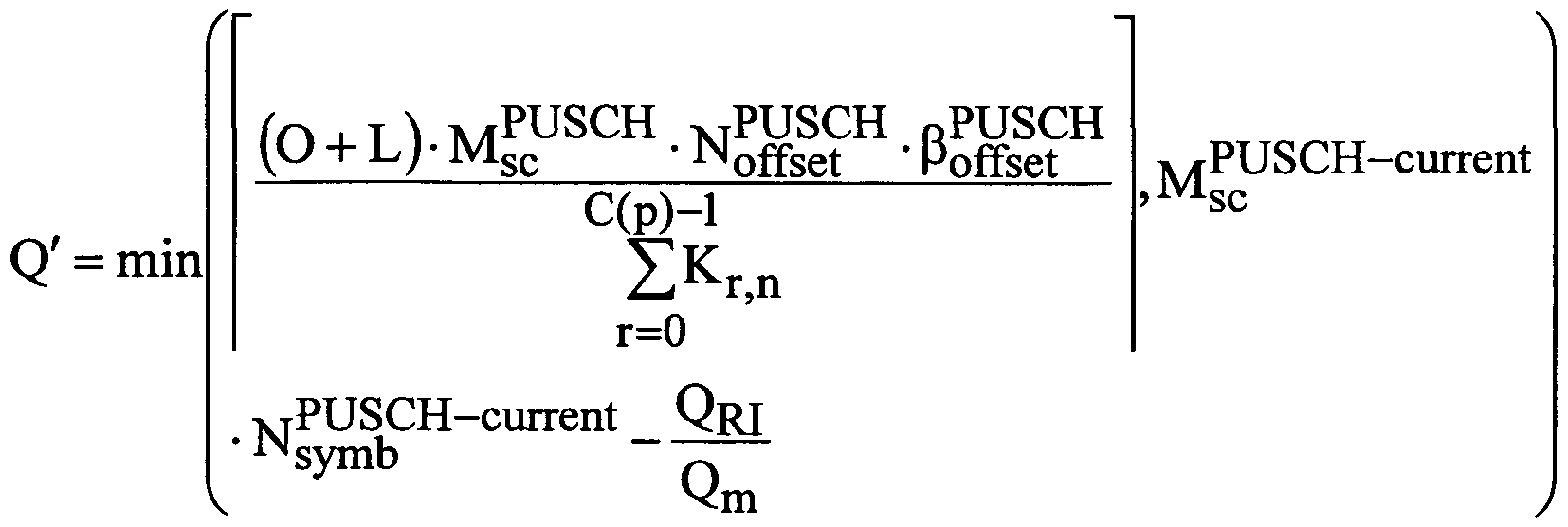
where Q' is one of a number of coded symbols for HARQ-ACK and rank
indicator, O is one of a number of ACK/NACK bits and rank indicator bits, L is a
PT JSCH number of CRC bits, Mf<f is tne scheduled bandwidth for a physical uplink
shared channel (PUSCH) transmission, M PUSCH-current
SC is the scheduled
bandwidth for PUSCH transmission in the current sub-frame for a transport block,
is a

number of SC-FDMA symbols per subframe for PUSCH transmission in the current
PUSCH sub-frame for the transport block, βoffSet 's an °ffset QRI corresponds to a rank
indicator, Qm is a number of symbols, N denotes a number of layers, C(n) denotes a
number of code blocks (CB) in layer n, and Kr n denotes a size of the rth CB in
layer n.
[Claim 17]
The base station of Claim 13, wherein the data and uplink control
information to is alternately mapped to different ones of the layers of the plurality of
layers such that the at least one layer is a first layer during a first transmission and a
second layer during a first re-transmission.
[Claim 18]
The base station of Claim 12, wherein the data and uplink control information is mapped to a subset of layers.
[Claim 19]
The base station of Claim 18, wherein the data and uplink control information is distributed evenly across the subset of layers.
[Claim 20]
The base station of Claim 18, wherein the uplink transmission comprises at least two component carriers and wherein uplink control information for each of the at least two component carriers is received separately within the subset of layers.
[Claim 21 ]
The base station of Claim 18, wherein the base station explicitly signals the subset of layers via an uplink scheduling grant.
[Claim 22]
The base station of Claim 18, wherein the subset of layers is determined based in part on at least one of: a number of codewords; a codeword to layer mapping structure; and a codeword that uses a modulation and coding scheme corresponding to a highest spectral efficiency among all layers.
[Claim 23]
For use in a Multiple Input Multiple Output wireless network, a method for
communicating uplink control information via an uplink transmission, the method comprising: mapping data and uplink control information to at least one layer, the mapping performed prior to DFT precoding such that the data and uplink control information are multiplexed and interleaved; and simultaneously transmitting the data and uplink control information on the at least one layer.
[Claim 24]
The method of Claim 23, wherein mapping further comprises selecting the at least one layer to simultaneously transmit the data and uplink control information.
[Claim 25]
The method of Claim 24, further comprising receiving signaling for the selection of the at least one layer via an uplink scheduling grant.
[Claim 26]
The method of Claim 24, wherein mapping further comprises alternately mapping the data and uplink control information to different layers such that the at least one layer is a first layer during a first transmission and a second layer during a first re-transmission.
[Claim 27]
The method of Claim 24, wherein mapping further comprises selecting the at least one layer to simultaneously transmit the data and uplink control information based on at least one of a modulation and coding scheme; and an order of the layers.
[Claim 28]
The method of Claim 27, wherein, when the at least one layer is a first
indexed layer, a control region size in the at least one layer is defined by at least one
of:
λ iv/irPscUSCH-current

and

where Q' is one of a number of coded symbols for HARQ-ACK and rank
indicator, O is one of a number of ACK/NACK bits and rank indicator bits, L is a
PTlSCH number of CRC bits, Ms<f is tne scheduled bandwidth for a physical uplink
shared channel (PUSCH) transmission, M PUSCH-current
SC is the scheduled
bandwidth for PUSCH transmission in the current sub-frame for a transport block,
NrmbCH "S a number of SC-FDMA symbols per subframe, N^£H~current is a
number of SC-FDMA symbols per subframe for PUSCH transmission in the current
PTJSCH sub-frame for the transport block, βoffset 's an °ffset. QRI corresponds to a rank
indicator, Qm is a number of symbols, N denotes a number of layers, C(n) denotes a
number of code blocks (CB) in layer n, and κr I , n U denotes a size of the rth CB in layer n.
[Claim 29]
The method of Claim 27, wherein, when the at least one layer is a layer with a modulation and coding scheme corresponding to a highest spectral efficiency among all layers, a control region size in the at least one layer is defined by at least one of:
)' λ/TPUSCH-current
 and
and

PTTSCH number of CRC bits, M^f is the scheduled bandwidth for a physical uplink
PUSCH-current shared channel (PUSCH) transmission, M SC is the scheduled bandwidth for PUSCH transmission in the current sub-frame for a transport block,
N^b CH is a number of SC-FDMA symbols per subframe, N^£H~cmτent is a
number of SC-FDMA symbols per subframe for PUSCH transmission in the current
PT TSCT-T sub-frame for the transport block, βoffset is an offset- QRI corresponds to a rank
indicator, Qm is a number of symbols, N denotes a number of layers, C(n) denotes a
number of code blocks (CB) in layer n, and Kr n denotes a size of the rth CB in
layer n.
[Claim 30]
The method of Claim 23, wherein mapping further comprises mapping the
data and uplink control information to a subset of layers.
[Claim 31 ]
The method of Claim 30, wherein the data and uplink control information is
distributed evenly across the subset of layers.
[Claim 32]
The method of Claim 30, wherein the uplink transmission comprises at least
two component carriers and wherein the step of mapping comprises mapping the
uplink control information for each of the at least two component carriers separately
within the subset of layers.
[Claim 33]
The method of Claim 30, wherein mapping the data and uplink control
information to a subset of layers further comprises receiving signaling for the
selection of the subset of layers in an uplink scheduling grant.
[Claim 34]
The method of Claim 30, mapping the data and uplink control information to a subset of layers further comprises determining the subset of layers based on at least one of: a number of codewords; a codeword to layer mapping structure; and a codeword that uses a modulation and coding scheme corresponding to a highest spectral efficiency among all layers.
Priority Applications (1)
| Application Number | Priority Date | Filing Date | Title |
|---|---|---|---|
| EP10736032.3A EP2384553B1 (en) | 2009-01-30 | 2010-01-29 | System and method for uplink data and control signal transmission in mimo wireless systems |
Applications Claiming Priority (4)
| Application Number | Priority Date | Filing Date | Title |
|---|---|---|---|
| US20645509P | 2009-01-30 | 2009-01-30 | |
| US61/206,455 | 2009-01-30 | ||
| US12/641,951 US8625554B2 (en) | 2009-01-30 | 2009-12-18 | System and method for uplink data and control signal transmission in MIMO wireless systems |
| US12/641,951 | 2009-12-18 |
Publications (2)
| Publication Number | Publication Date |
|---|---|
| WO2010087641A2 true WO2010087641A2 (en) | 2010-08-05 |
| WO2010087641A3 WO2010087641A3 (en) | 2010-11-04 |
Family
ID=42396198
Family Applications (1)
| Application Number | Title | Priority Date | Filing Date |
|---|---|---|---|
| PCT/KR2010/000545 WO2010087641A2 (en) | 2009-01-30 | 2010-01-29 | System and method for uplink data and control signal transmission in mimo wireless systems |
Country Status (3)
| Country | Link |
|---|---|
| US (1) | US8625554B2 (en) |
| EP (1) | EP2384553B1 (en) |
| WO (1) | WO2010087641A2 (en) |
Cited By (7)
| Publication number | Priority date | Publication date | Assignee | Title |
|---|---|---|---|---|
| EP2306667A2 (en) * | 2009-10-01 | 2011-04-06 | Electronics and Telecommunications Research Institute | Method of transmitting control information using physical uplink shared channel region in MIMO antenna system |
| WO2012161533A3 (en) * | 2011-05-24 | 2013-03-21 | 엘지전자 주식회사 | Method for transmitting control information and apparatus therefor |
| EP2572465A1 (en) * | 2010-06-21 | 2013-03-27 | Huawei Technologies Co., Ltd. | System and method for control information multiplexing for uplink multiple input, multiple output |
| RU2516484C2 (en) * | 2010-01-11 | 2014-05-20 | Хуавей Текнолоджиз Ко., Лтд. | System and method for multiplexing control and data channels in multiple input, multiple output (mimo) communication system |
| EP2882124A4 (en) * | 2012-07-31 | 2016-04-06 | Nec Corp | Wireless communication apparatus, and harq response transmitting method and receiving method |
| RU2658901C1 (en) * | 2014-12-11 | 2018-06-25 | Хуавэй Текнолоджиз Ко., Лтд. | Method, apparatus and device for data processing |
| RU2703234C1 (en) * | 2015-12-01 | 2019-10-15 | Телефонактиеболагет Лм Эрикссон (Пабл) | Acknowledgment handshaking feedback mechanism |
Families Citing this family (50)
| Publication number | Priority date | Publication date | Assignee | Title |
|---|---|---|---|---|
| US8553624B2 (en) | 2007-10-10 | 2013-10-08 | Samsung Electronics Co., Ltd. | Asynchronous hybrid ARQ process indication in a MIMO wireless communication system |
| KR100925444B1 (en) | 2008-05-27 | 2009-11-06 | 엘지전자 주식회사 | A method for transmitting uplink siganl including data and control inforamtion via uplink channel |
| WO2010093217A2 (en) * | 2009-02-16 | 2010-08-19 | 엘지전자주식회사 | Method for transmitting data in multiple antenna system |
| KR101649458B1 (en) | 2009-03-16 | 2016-08-19 | 인터디지탈 패튼 홀딩스, 인크 | Data and control multiplexing for uplink mimo with carrier aggregation and clustered-dft |
| US8737503B2 (en) * | 2009-03-17 | 2014-05-27 | Futurewei Technologies, Inc. | System and method for multiple input, multiple output layer mapping |
| JP5212539B2 (en) * | 2009-03-25 | 2013-06-19 | 富士通株式会社 | Radio communication system, mobile station apparatus, base station apparatus, and radio communication method in radio communication system |
| WO2010123893A1 (en) * | 2009-04-22 | 2010-10-28 | Interdigital Patent Holdings, Inc. | Method and apparatus for transmitting uplink control information for carrier aggregated spectrums |
| US9236985B2 (en) * | 2009-04-23 | 2016-01-12 | Qualcomm Incorporated | Method and apparatus for control and data multiplexing in a MIMO communication system |
| CN103945547B (en) * | 2009-04-24 | 2017-09-08 | 夏普株式会社 | Wireless communication system, communicator, communication means and signal procedure |
| JP5122529B2 (en) * | 2009-06-23 | 2013-01-16 | 株式会社エヌ・ティ・ティ・ドコモ | Mobile terminal apparatus, radio base station apparatus, radio communication method, and radio communication system |
| CN101695017A (en) * | 2009-10-27 | 2010-04-14 | 中兴通讯股份有限公司 | Method and device for transmitting an uplink control signaling on a physical uplink shared channel |
| KR101148727B1 (en) * | 2009-12-15 | 2012-05-21 | 한국전자통신연구원 | Data transmission system for transmitting control information to basestation |
| KR20110073189A (en) * | 2009-12-21 | 2011-06-29 | 엘지전자 주식회사 | A method and an apparatus for transmitting uplink data and control information in wireless communication system supporting multiple input multiple output |
| KR101327131B1 (en) * | 2010-02-12 | 2013-11-07 | 엘지전자 주식회사 | Method and apparatus of transmitting data in wireless communication system |
| KR101791266B1 (en) * | 2010-02-12 | 2017-10-30 | 엘지전자 주식회사 | Method and apparatus of transmitting data in wireless communication system |
| CN104579604B (en) * | 2010-03-31 | 2019-12-06 | 三星电子株式会社 | Method for confirming index resource of signal transmission, user equipment and base station |
| CN101807974B (en) * | 2010-04-07 | 2015-05-20 | 中兴通讯股份有限公司 | System and method for transferring ascending control signals on physical upstream sharing channel |
| CN102255696B (en) * | 2010-04-07 | 2016-03-30 | 华为技术有限公司 | A kind of method of transmitting uplink control information, subscriber equipment and base station |
| US8670496B2 (en) * | 2010-04-14 | 2014-03-11 | Samsung Electronics Co., Ltd. | Method and system for mapping uplink control information |
| CN102237991B (en) * | 2010-04-30 | 2016-08-24 | 北京三星通信技术研究有限公司 | The method sending ACK/NACK information in a tdd system |
| WO2011135551A1 (en) | 2010-04-30 | 2011-11-03 | Telefonaktiebolaget L M Ericsson (Publ) | System and method for allocating transmission resources |
| US9100155B2 (en) * | 2010-05-03 | 2015-08-04 | Qualcomm Incorporated | Method and apparatus for control and data multiplexing in wireless communication |
| ES2647157T3 (en) * | 2010-05-10 | 2017-12-19 | Telefonaktiebolaget Lm Ericsson (Publ) | System and procedure for allocating transmission resources |
| US8879513B2 (en) | 2010-05-12 | 2014-11-04 | Samsung Electronics Co., Ltd. | Uplink transmission apparatus and method for mobile communication system supporting uplink MIMO |
| WO2011142626A2 (en) | 2010-05-13 | 2011-11-17 | 엘지전자 주식회사 | Method and apparatus for multiplexing control information and data, and for transmitting the multiplexed control information and data in a mimo wireless communication system |
| WO2011149286A2 (en) * | 2010-05-26 | 2011-12-01 | 엘지전자 주식회사 | Method and apparatus for transceiving control information for uplink multi-antenna transmission |
| EP2395693B1 (en) * | 2010-06-08 | 2023-03-01 | Samsung Electronics Co., Ltd. | Multiplexing Control and Data Information From a User Equipment in MIMO Transmission Mode |
| US8634367B2 (en) * | 2010-06-21 | 2014-01-21 | Telefonaktiebolaget Lm Ericsson (Publ) | System and method for allocating transmission resources |
| WO2011161887A1 (en) * | 2010-06-21 | 2011-12-29 | パナソニック株式会社 | Terminal apparatus and communication method thereof |
| CN102014506B (en) * | 2010-07-13 | 2012-08-29 | 华为技术有限公司 | Method, and base station for triggering terminal to transmit measurement reference signals |
| CN101969361B (en) * | 2010-09-30 | 2015-06-03 | 中兴通讯股份有限公司 | Method and device for transmitting cycle feedback report |
| WO2012050330A2 (en) * | 2010-10-10 | 2012-04-19 | 엘지전자 주식회사 | Method and device for transmitting uplink control information in wireless access system |
| WO2012053863A2 (en) | 2010-10-21 | 2012-04-26 | Lg Electronics Inc. | Method and apparatus for transmitting control information in a wireless communication system |
| KR101233186B1 (en) | 2010-10-21 | 2013-02-15 | 엘지전자 주식회사 | Method and apparutus for transmitting control information |
| WO2012057480A2 (en) * | 2010-10-27 | 2012-05-03 | 엘지전자 주식회사 | Method for transmitting control information in a wireless communication system, and device therefor |
| CN107835069B (en) * | 2010-11-03 | 2021-06-18 | 三星电子株式会社 | Method for encoding acknowledgement information bits by user equipment and user equipment |
| US8830883B2 (en) * | 2010-11-16 | 2014-09-09 | Qualcomm Incorporated | Method and apparatus for improving acknowledgement/negative acknowledgement feedback |
| US9716573B2 (en) | 2014-06-13 | 2017-07-25 | Futurewei Technologies, Inc. | Aggregated touchless wireless fronthaul |
| WO2016124457A1 (en) * | 2015-02-02 | 2016-08-11 | Telefonaktiebolaget Lm Ericsson (Publ) | Selective codeword-to-layer mapping for mimo transmissions |
| EP3254395B1 (en) | 2015-02-06 | 2019-06-19 | Samsung Electronics Co., Ltd. | Method and apparatus for controlling uplink control information transmission in wireless communication system providing widebandwidth services via carrier aggregation |
| US9755779B2 (en) * | 2015-04-17 | 2017-09-05 | Futurewei Technologies, Inc. | Digital representations of analog signals and control words using different multi-level modulation formats |
| US10206211B2 (en) * | 2015-06-04 | 2019-02-12 | Futurewei Technologies, Inc. | Device, network, and method for wideband long-term evolution (LTE) uplink transmission |
| US10027413B2 (en) | 2015-06-18 | 2018-07-17 | Futurewei Technologies, Inc. | Cascaded waveform modulation with an embedded control signal for high-performance mobile fronthaul |
| JP6817945B2 (en) * | 2015-08-31 | 2021-01-20 | 株式会社Nttドコモ | User terminal, wireless base station and wireless communication method |
| TW201806349A (en) * | 2016-08-10 | 2018-02-16 | Idac控股公司 | Methods for flexible reference signal transmission with single carrier frequency domain multiple access (SC-FDMA) and OFDMA |
| US10631329B2 (en) * | 2016-08-12 | 2020-04-21 | Qualcomm Incorporated | Non-coherent joint transmission techniques |
| US10440698B2 (en) * | 2017-02-06 | 2019-10-08 | Qualcomm Incorporated | Transmitting uplink control information |
| US10944512B2 (en) * | 2017-11-17 | 2021-03-09 | Qualcomm Incorporated | Code block group retransmission |
| US11546858B2 (en) * | 2018-03-23 | 2023-01-03 | Qualcomm Incorporated | Power control techniques for uplink control information transmissions in wireless communications |
| WO2020204540A1 (en) * | 2019-03-29 | 2020-10-08 | 엘지전자 주식회사 | Method for transmitting or receiving data in wireless communication system, and apparatus therefor |
Family Cites Families (13)
| Publication number | Priority date | Publication date | Assignee | Title |
|---|---|---|---|---|
| US7593357B2 (en) * | 2002-03-28 | 2009-09-22 | Interdigital Technology Corporation | Transmit processing using receiver functions |
| US7257167B2 (en) * | 2003-08-19 | 2007-08-14 | The University Of Hong Kong | System and method for multi-access MIMO channels with feedback capacity constraint |
| KR100584090B1 (en) * | 2003-12-27 | 2006-05-29 | 한국전자통신연구원 | A method for pre-processing for an uplink of OFDM communication system |
| KR100918747B1 (en) * | 2006-02-07 | 2009-09-24 | 삼성전자주식회사 | Apparatus and method for transmitting uplink signal in mobile communication system using an orthogonal frequency division multiple access scheme |
| CN101507170B (en) * | 2006-08-25 | 2012-12-26 | 高通股份有限公司 | CDMA wireless communication systems |
| EP1928115A1 (en) * | 2006-11-30 | 2008-06-04 | Nokia Siemens Networks Gmbh & Co. Kg | Adaptive modulation and coding in a SC-FDMA system |
| KR101531416B1 (en) * | 2007-09-13 | 2015-06-24 | 옵티스 셀룰러 테크놀로지, 엘엘씨 | Method For Transmitting Uplink Signals |
| TW200931869A (en) * | 2007-12-31 | 2009-07-16 | Interdigital Patent Holdings | Method and apparatus for handling interactions between measurement gap, automated repeat request, discontinuous reception and discontinuous transmission in wireless communications |
| JP2011527137A (en) * | 2008-07-03 | 2011-10-20 | テレフオンアクチーボラゲット エル エム エリクソン(パブル) | Method and configuration in a wireless communication system |
| KR20100017039A (en) * | 2008-08-05 | 2010-02-16 | 엘지전자 주식회사 | Method for transmitting data in multiple antenna system |
| WO2010018969A2 (en) * | 2008-08-11 | 2010-02-18 | Lg Electronics Inc. | Method and apparatus for transmitting uplink signals using multi-antenna |
| CN103945547B (en) * | 2009-04-24 | 2017-09-08 | 夏普株式会社 | Wireless communication system, communicator, communication means and signal procedure |
| JP5122529B2 (en) * | 2009-06-23 | 2013-01-16 | 株式会社エヌ・ティ・ティ・ドコモ | Mobile terminal apparatus, radio base station apparatus, radio communication method, and radio communication system |
-
2009
- 2009-12-18 US US12/641,951 patent/US8625554B2/en active Active
-
2010
- 2010-01-29 WO PCT/KR2010/000545 patent/WO2010087641A2/en active Application Filing
- 2010-01-29 EP EP10736032.3A patent/EP2384553B1/en active Active
Non-Patent Citations (3)
| Title |
|---|
| NOKIA SIEMENS NETWORKS ET AL.: "3GPP DRAFT; R1-082609, 3RD GENERATION PARTNERSHIP PROJECT (3GPP", 25 June 2008, MOBILE COMPETENCE CENTRE, article "Uplink Multiple access for LTE-Advanced" |
| QUALCOMM EUROPE: "3GPP DRAFT; R1-073269, 3RD GENERATION PARTNERSHIP PROJECT (3GPP", vol. RAN WG1, 15 August 2007, MOBILE COMPETENCE CENTRE, article "Rate matching details for control and data multiplexing" |
| See also references of EP2384553A4 |
Cited By (24)
| Publication number | Priority date | Publication date | Assignee | Title |
|---|---|---|---|---|
| EP2306667A2 (en) * | 2009-10-01 | 2011-04-06 | Electronics and Telecommunications Research Institute | Method of transmitting control information using physical uplink shared channel region in MIMO antenna system |
| US10506563B2 (en) | 2009-10-01 | 2019-12-10 | Electronics And Telecommunications Research Institute | Method of transmitting control information using physical uplink shared channel region in MIMO antenna system |
| EP3567788A1 (en) * | 2009-10-01 | 2019-11-13 | Electronics and Telecommunications Research Institute | Method of transmitting control information using physical uplink shared channel region in mimo antenna system |
| US9462573B2 (en) | 2009-10-01 | 2016-10-04 | Electronics And Telecommunications Research Institute | Method of transmitting control information using physical uplink shared channel region in MIMO antenna system |
| EP2634951A1 (en) * | 2009-10-01 | 2013-09-04 | Electronics and Telecommunications Research Institute | Method of transmitting control information using physical uplink shared channel region in MIMO antenna system |
| EP2634952A1 (en) * | 2009-10-01 | 2013-09-04 | Electronics and Telecommunications Research Institute | Method of transmitting control information using physical uplink shared channel region in MIMO antenna system |
| RU2516484C2 (en) * | 2010-01-11 | 2014-05-20 | Хуавей Текнолоджиз Ко., Лтд. | System and method for multiplexing control and data channels in multiple input, multiple output (mimo) communication system |
| US9544034B2 (en) | 2010-01-11 | 2017-01-10 | Futurewei Technologies, Inc. | System and method for multiplexing control and data channels in a multiple input, multiple output communications system |
| US10396870B2 (en) | 2010-01-11 | 2019-08-27 | Futurewei Technologies, Inc. | System and method for multiplexing control and data channels in a multiple input, multiple output communications system |
| US9270427B2 (en) | 2010-01-11 | 2016-02-23 | Futurewei Technologies, Inc. | System and method for multiplexing control and data channels in a multiple input, multiple output communications system |
| EP3461051A1 (en) * | 2010-01-11 | 2019-03-27 | Huawei Technologies Co., Ltd. | System and method for multiplexing control and data channels in a multiple input, multiple output communications system |
| US9935696B2 (en) | 2010-01-11 | 2018-04-03 | Futurewei Technologies, Inc. | System and method for multiplexing control and data channels in a multiple input, multiple output communications system |
| EP3021508A1 (en) * | 2010-06-21 | 2016-05-18 | Huawei Technologies Co., Ltd. | System and method for control information multiplexing for uplink multiple input, multiple output |
| EP2572465A4 (en) * | 2010-06-21 | 2013-05-22 | Huawei Tech Co Ltd | System and method for control information multiplexing for uplink multiple input, multiple output |
| US8891461B2 (en) | 2010-06-21 | 2014-11-18 | Futurewei Technologies, Inc. | System and method for control information multiplexing for uplink multiple input, multiple output |
| EP2572465A1 (en) * | 2010-06-21 | 2013-03-27 | Huawei Technologies Co., Ltd. | System and method for control information multiplexing for uplink multiple input, multiple output |
| US9584298B2 (en) | 2011-05-24 | 2017-02-28 | Lg Electronics Inc. | Method for transmitting control information and apparatus therefor |
| US9887812B2 (en) | 2011-05-24 | 2018-02-06 | Lg Electronics Inc. | Method for transmitting control information and apparatus therefor |
| US8855027B2 (en) | 2011-05-24 | 2014-10-07 | Lg Electronics Inc. | Method for transmitting control information and apparatus therefor |
| WO2012161533A3 (en) * | 2011-05-24 | 2013-03-21 | 엘지전자 주식회사 | Method for transmitting control information and apparatus therefor |
| EP2882124A4 (en) * | 2012-07-31 | 2016-04-06 | Nec Corp | Wireless communication apparatus, and harq response transmitting method and receiving method |
| RU2658901C1 (en) * | 2014-12-11 | 2018-06-25 | Хуавэй Текнолоджиз Ко., Лтд. | Method, apparatus and device for data processing |
| RU2703234C1 (en) * | 2015-12-01 | 2019-10-15 | Телефонактиеболагет Лм Эрикссон (Пабл) | Acknowledgment handshaking feedback mechanism |
| US11005603B2 (en) | 2015-12-01 | 2021-05-11 | Telefonaktiebolaget Lm Ericsson (Publ) | Predictive acknowledgment feedback mechanism |
Also Published As
| Publication number | Publication date |
|---|---|
| EP2384553A4 (en) | 2017-08-02 |
| WO2010087641A3 (en) | 2010-11-04 |
| EP2384553B1 (en) | 2021-12-08 |
| US8625554B2 (en) | 2014-01-07 |
| EP2384553A2 (en) | 2011-11-09 |
| US20100195624A1 (en) | 2010-08-05 |
Similar Documents
| Publication | Publication Date | Title |
|---|---|---|
| EP2384553B1 (en) | System and method for uplink data and control signal transmission in mimo wireless systems | |
| US20200178246A1 (en) | Multiplexing large payloads of control information from user equipments | |
| EP2520032B1 (en) | Uplink demodulation reference signal design for mimo transmission | |
| CN110063039B (en) | Method and apparatus for multiplexing control information in physical uplink data channel | |
| KR101776097B1 (en) | Method and system for mapping uplink control information | |
| US20200145989A1 (en) | Uplink data transmission method and device | |
| KR101838203B1 (en) | Methods and apparatus for multi-user mimo transmissions in wireless communication systems | |
| US8259643B2 (en) | Apparatus and method for codeword to layer mapping in MIMO transmission wireless systems | |
| US8611238B2 (en) | Multiplexing large payloads of control information from user equipments | |
| KR101770174B1 (en) | Method and system of multi-layer beamforming | |
| EP3261281B1 (en) | System and method for multi-user and multi-cell mimo transmissions | |
| KR101726601B1 (en) | Method and system for indicating the transmission mode for uplink control information | |
| KR101643258B1 (en) | Method for allocating resource block in long term evolution system | |
| KR101920241B1 (en) | Multiplexing of control and data in ul mimo system based on sc-fdm | |
| US20100172308A1 (en) | System and method for downlink physical indicator channel mapping with asymmetric carrier aggregation | |
| US20130201926A1 (en) | System and method for physical downlink control and hybrid-arq indicator channels in lte-a systems | |
| CN107005391A (en) | Transmission of the uplink control information in the carrier aggregation with many cells | |
| CN108352916A (en) | For monitoring the method and apparatus for exempting from the control channel in licensed band |
Legal Events
| Date | Code | Title | Description |
|---|---|---|---|
| 121 | Ep: the epo has been informed by wipo that ep was designated in this application |
Ref document number: 10736032 Country of ref document: EP Kind code of ref document: A2 |
|
| WWE | Wipo information: entry into national phase |
Ref document number: 2010736032 Country of ref document: EP |
|
| NENP | Non-entry into the national phase |
Ref country code: DE |