WO2010087620A2 - Procédé et appareil de codage et de décodage d'images par utilisation adaptative d'un filtre d'interpolation - Google Patents
Procédé et appareil de codage et de décodage d'images par utilisation adaptative d'un filtre d'interpolation Download PDFInfo
- Publication number
- WO2010087620A2 WO2010087620A2 PCT/KR2010/000506 KR2010000506W WO2010087620A2 WO 2010087620 A2 WO2010087620 A2 WO 2010087620A2 KR 2010000506 W KR2010000506 W KR 2010000506W WO 2010087620 A2 WO2010087620 A2 WO 2010087620A2
- Authority
- WO
- WIPO (PCT)
- Prior art keywords
- image block
- block
- interpolation filter
- filter
- information
- Prior art date
Links
Images


Classifications
-
- H—ELECTRICITY
- H04—ELECTRIC COMMUNICATION TECHNIQUE
- H04N—PICTORIAL COMMUNICATION, e.g. TELEVISION
- H04N19/00—Methods or arrangements for coding, decoding, compressing or decompressing digital video signals
- H04N19/80—Details of filtering operations specially adapted for video compression, e.g. for pixel interpolation
-
- H—ELECTRICITY
- H04—ELECTRIC COMMUNICATION TECHNIQUE
- H04N—PICTORIAL COMMUNICATION, e.g. TELEVISION
- H04N19/00—Methods or arrangements for coding, decoding, compressing or decompressing digital video signals
- H04N19/10—Methods or arrangements for coding, decoding, compressing or decompressing digital video signals using adaptive coding
- H04N19/102—Methods or arrangements for coding, decoding, compressing or decompressing digital video signals using adaptive coding characterised by the element, parameter or selection affected or controlled by the adaptive coding
- H04N19/124—Quantisation
-
- H—ELECTRICITY
- H04—ELECTRIC COMMUNICATION TECHNIQUE
- H04N—PICTORIAL COMMUNICATION, e.g. TELEVISION
- H04N19/00—Methods or arrangements for coding, decoding, compressing or decompressing digital video signals
- H04N19/10—Methods or arrangements for coding, decoding, compressing or decompressing digital video signals using adaptive coding
- H04N19/102—Methods or arrangements for coding, decoding, compressing or decompressing digital video signals using adaptive coding characterised by the element, parameter or selection affected or controlled by the adaptive coding
- H04N19/117—Filters, e.g. for pre-processing or post-processing
-
- H—ELECTRICITY
- H04—ELECTRIC COMMUNICATION TECHNIQUE
- H04N—PICTORIAL COMMUNICATION, e.g. TELEVISION
- H04N19/00—Methods or arrangements for coding, decoding, compressing or decompressing digital video signals
- H04N19/10—Methods or arrangements for coding, decoding, compressing or decompressing digital video signals using adaptive coding
- H04N19/102—Methods or arrangements for coding, decoding, compressing or decompressing digital video signals using adaptive coding characterised by the element, parameter or selection affected or controlled by the adaptive coding
- H04N19/124—Quantisation
- H04N19/126—Details of normalisation or weighting functions, e.g. normalisation matrices or variable uniform quantisers
-
- H—ELECTRICITY
- H04—ELECTRIC COMMUNICATION TECHNIQUE
- H04N—PICTORIAL COMMUNICATION, e.g. TELEVISION
- H04N19/00—Methods or arrangements for coding, decoding, compressing or decompressing digital video signals
- H04N19/50—Methods or arrangements for coding, decoding, compressing or decompressing digital video signals using predictive coding
- H04N19/503—Methods or arrangements for coding, decoding, compressing or decompressing digital video signals using predictive coding involving temporal prediction
- H04N19/51—Motion estimation or motion compensation
- H04N19/523—Motion estimation or motion compensation with sub-pixel accuracy
-
- H—ELECTRICITY
- H04—ELECTRIC COMMUNICATION TECHNIQUE
- H04N—PICTORIAL COMMUNICATION, e.g. TELEVISION
- H04N19/00—Methods or arrangements for coding, decoding, compressing or decompressing digital video signals
- H04N19/60—Methods or arrangements for coding, decoding, compressing or decompressing digital video signals using transform coding
- H04N19/61—Methods or arrangements for coding, decoding, compressing or decompressing digital video signals using transform coding in combination with predictive coding
Definitions
- the present invention relates to encoding and decoding of an image, and more particularly, to a method and an apparatus for encoding and decoding an image by using an interpolation filter in consideration of characteristics of an input image.
- H.264 / AVC MPEG-4 Advanced video Coding
- MPEG-1 MPEG-1
- MPEG-2 MPEG-2
- MPEG-4 MPEG-4 Advanced video Coding
- H.264 / AVC uses an intra encoding mode and an inter encoding mode to provide high efficiency encoding. To provide.
- Intra coding mode is a technique of encoding using a high spatial correlation within one image frame.
- the intra coding mode generates prediction data using neighboring image blocks of a current image block to be encoded, and then It is a technique to remove redundancy.
- the inter encoding mode is a technique for encoding by using a high temporal correlation between images, and after generating prediction data using current or previous images, removing temporal redundancy.
- the inter-screen encoding method precisely generates prediction data using an interpolation filter before searching for a prediction block.
- the existing image interpolation technique performs repetitive interpolation using only one predetermined interpolation filter without considering characteristics of the input image. Therefore, in a recent multimedia communication environment in which various images exist, there is a problem in that it is impossible to generate various more accurate prediction data, that is, the input image is not optimized and interpolated. In addition, with respect to the processing of high-quality and large-capacity images, there is a problem that has a high computational complexity.
- the present invention provides a method and apparatus for encoding and decoding an image by applying an interpolation filter reflecting characteristics of an input image.
- the present invention also provides a method and apparatus for encoding and decoding an image by adaptively selecting an interpolation filter based on context information of an image block in a plurality of adaptive interpolation filter groups.
- the present invention also provides a method and apparatus for generating a prediction block by adaptively selecting a specific interpolation filter based on context information of an image block when encoding and decoding an inter-screen image.
- the present invention also provides a method and apparatus for generating a prediction block by selectively applying an interpolation filter based on context information of an image block when encoding and decoding an image between screens, and encoding and decoding an image using the prediction block. to provide.
- the present invention provides an apparatus for encoding an image, comprising: a selector for adaptively selecting an interpolation filter for generating a prediction block in consideration of context information of an input image block, and a plurality of interpolation filters corresponding to the context information; And a predictive block generator including a filter bank stored for each channel and a specific interpolation filter selected from the filter bank under the control of the selector and interpolating a reference image block associated with the input image block.
- the context information of the input image block means a macroblock or information related to the input image block that are adjacent in time / space from the input image block, and the context information includes, as the context information, spatially adjacent to the input image block. At least one of encoding mode information or quantization value of a block, position information of a pixel processed by a filter in a block adjacent in time, and resolution information of an interpolated pixel.
- the present invention provides an apparatus for decoding an image, comprising: a filter bank storing a plurality of interpolation filters by group, encoding mode information of a received image block, quantization value, pixel position information, and pixel resolution And a prediction block generation unit including a specific interpolation filter for interpolating a reference image block associated with the received image block selected from the filter banks by checking the interpolation filter information determined in consideration of at least one of the context information.
- the context information of the received image block means information related to the macroblock or the input image block adjacent in time / space from the received input image block, and the context information includes the information of the input image block. At least one of encoding mode information or quantization values of adjacent blocks in space, position information of pixels processed by a filter in adjacent blocks in time, and resolution information of interpolated pixels.
- the present invention provides a method of encoding an image, the encoding mode information or quantization value of the spatially adjacent block of the input image block, the position information of the pixel processed by the filter in the adjacent block in time or the resolution information of the interpolated pixel Adaptively selecting an interpolation filter from a filter bank storing a plurality of interpolation filters for each group in consideration of at least one piece of information, and using the selected interpolation filter, a reference image block associated with an input image block. Interpolating and determining an interpolation filter for minimizing an error difference between the input image block and the reference image block as an interpolation filter for generating a prediction block for the input image block.
- the present invention provides a method of decoding an image, comprising: encoding mode information or quantization value of a spatially adjacent block of a received image block, position information of a pixel processed by a filter in adjacent blocks in time, or resolution of an interpolated pixel Checking interpolation filter information determined in consideration of at least one piece of information, selecting an interpolation filter indicated by the interpolation filter information from a filter bank storing a plurality of interpolation filters by group, and interpolating filter And generating a prediction block by interpolating a reference picture block associated with the received picture block using.
- the present invention adaptively selects an interpolation filter for generating a prediction block by reflecting a macroblock adjacent to a time / space of an input image or context information which is information related to the input image block.
- a more precise interpolation process is provided by selectively using an interpolation filter having a minimum inter-picture prediction error between the input picture block and the reference picture block. That is, the present invention provides an advantage of improving compression performance by easily and precisely removing temporal redundancy by selecting and using an adaptive interpolation filter having a plurality of interpolation filter groups and considering characteristics of an image. It also provides the advantage of simplifying computational complexity during interpolation.
- the present invention provides a method for reducing the overhead of control information according to the use of the adaptive interpolation filter in a wireless channel environment. Therefore, it actively supports the transmission of high-quality and large-capacity image data, and supports adaptive and accurate interpolation processing for various images.
- 1 to 4 are diagrams showing an example of context information of an image block for selecting an optimal interpolation filter applied to the present invention.
- FIG. 5 illustrates the structure of a plurality of filter groups with various filters in accordance with the present invention.
- FIG. 6 through 9 illustrate slice structures including interpolation filter information according to the present invention.
- FIG. 10 is a flowchart illustrating the operation of selecting an interpolation filter in accordance with the present invention.
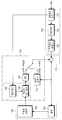
- FIG. 11 is a diagram illustrating a configuration of a video encoding apparatus according to the present invention.
- FIG. 12 is a flowchart illustrating an operation of performing image encoding according to an embodiment of the present invention.
- FIG. 13 is a diagram illustrating a configuration of an image decoding apparatus according to the present invention.
- FIG. 14 is a flowchart illustrating an operation of performing image decoding according to an embodiment of the present invention.
- the present invention is characterized in that an interpolation process is performed by selecting an interpolation filter reflecting characteristics of each of a plurality of macroblocks constituting an image slice type and a specific image slice.
- the present invention performs a more precise interpolation process by generating a prediction block by using an adaptive interpolation filter reflecting contextual information about an input image.
- the present invention encodes and decodes an image by selectively applying a specific interpolation filter among a plurality of filter groups corresponding to the input image. Therefore, the present invention increases the efficiency of image compression when encoding and decoding various images of high quality and large capacity.
- the filter selection for interpolation adaptively selects a specific interpolation filter among a plurality of filter groups by using context information of an image block.
- an interpolation filter for minimizing an error between the current image and the reference image is selected as an optimal interpolation filter.
- the context information of the input image block means a macroblock or information related to the input image block that are adjacent in time / space from the input image block
- the context information includes, as the context information, spatially adjacent to the input image block. At least one of encoding mode information or quantization value of a block, position information of a pixel processed by a filter in a block adjacent in time, and resolution information of an interpolated pixel.
- 1 to 4 are diagrams showing examples of context information of an image block for selecting an optimal interpolation filter applied to the present invention.
- FIG. 1 is a diagram illustrating encoding mode information of a macroblock adjacent in space as context information of an image block.
- one image slice 100 is a collection of a plurality of pixels.
- the image slice 100 may be divided into a plurality of macro blocks having a size of 16 ⁇ 16.
- MB refers to a basic unit of encoding processing for an image block, that is, a set of pixels of a predetermined size.
- the video block will be described by quoting the MB of a predetermined size.
- the image complexity of the input slice when it is low, it may be divided into MBs larger than 16x16 size, for example, MBs of 32x32 size.
- MB can be encoded with a different coding mode corresponding to a predetermined size, for example, H.264, an international standard established by the ITU-T SG16 / Q6 VCEG (VC Coding Expert Group) standardization body
- a predetermined size for example, H.264, an international standard established by the ITU-T SG16 / Q6 VCEG (VC Coding Expert Group) standardization body
- an intra coding mode for predicting pixels from spatially adjacent pixels in units of a predetermined block size, for example, 16x16, 8x8, or 4x4, and in certain block sizes, for example, 16x16, 16x8, 8x16, 8x8, 8x4.
- the MB 110 shows an Inter coding mode (that is, an A type) of 16 ⁇ 16 units
- the MB 112 shows an Intra coding mode of 4 ⁇ 4 units. (That is, type B) is shown to be applied.
- the interpolation filter is adaptively selected and interpolated by considering the encoding mode of the MB 111 to be currently encoded.
- FIG. 2 is a diagram illustrating a quantization value as context information of an image block.
- the MB of a predetermined size is transmitted through quantization in order to use a limited radio resource more efficiently. More specifically, the spectral data output from a Discrete Cosine Transform (DCT) for a specific image block is quantized. Parameter, hereinafter referred to as 'QP', is mapped and transmitted as a constant scalar value. This is because, by transmitting mapped scalar values rather than transmitting spectral data directly through radio resources, limited radio resources can be used more efficiently.
- DCT Discrete Cosine Transform
- the encoding apparatus on the transmitting side transmits the 0 or 1 scalar value
- the decoding apparatus on the receiving side receives the 0 or 1 scalar value, dequantizes, and restores the corresponding video block.
- the zero scalar value may be restored to spectral data 0, even though it is actually spectral data in the range of 0-9. Therefore, there may be a problem in that data loss increases between the actually transmitted image block and the image block interpolated at the receiving side.
- the MB 120 applies a quantization parameter A type (eg, QP-10), and the MB 122 shows a quantization parameter C type (eg, QP-5). .
- the present invention performs interpolation by adaptively selecting an interpolation filter for generating a prediction block in consideration of the QP value for each MB.
- the interpolation filter having the minimum error difference between the current image block and the reference image block is selected as an optimal interpolation filter by referring to the interpolation processing result of each of the adaptively selected interpolation filters.
- the interpolation filter may be differently selected in consideration of whether there are orthogonal transform coefficients or distributions of digital transform (DC) and analog transform (AC) in relation to the frequency converter (DCT).
- FIG. 3 is a diagram illustrating position information of a pixel to which a filter is applied when interpolating a previous image as context information of an image block.
- reference numerals 130 and 140 denote two adjacent macro blocks in the previous image, respectively.
- whether a specific MB to be encoded is located in the area A 131 of the macro block 130 or two macros.
- the interpolation filter for the B region 135 may be a filter that requires a higher intensity interpolation process than the interpolation filter applied to the A region 130. Accordingly, the present invention performs interpolation processing in consideration of the positional information of the MB of pixels to be interpolated, that is, the interpolation filter is applied.
- FIG. 4 is a diagram illustrating resolution of pixels interpolated with image block context information.
- the interpolation filter can be chosen differently based on whether / N resolution pixel values are interpolated.
- MB edge information may be further included as context information of the image block. That is, different interpolation filters may be applied in consideration of whether edge information or edge information does not exist in the image block. In this case, the interpolation filter is applied in consideration of some direction of the edge information. As an example, it is necessary to use an interpolation filter for different interpolation processes in consideration of whether the edge is horizontal, vertical, or diagonal.
- FIG. 5 is a diagram illustrating a structure of a plurality of filter groups having various filters according to the present invention.
- the filter groups may consider characteristics of an input image slice or distinguish between MB-based encoding mode information, QP value, pixel position information, and resolution among a plurality of MBs constituting one slice. do.
- Each filter group may be additionally grouped by edge information of the corresponding MB block.
- the first filter group 210 illustrates interpolation filters arranged in descending or ascending order in consideration of the QP value when the encoding mode information is applied to the input image in units of 16 ⁇ 16.
- the first filter group may include interpolation filters arranged in descending or ascending order in consideration of the position information of the pixel.
- the filters may be arranged to reflect the resolution.
- the second filter group 220 is arranged in a predetermined order in consideration of at least one or more context information among a QP value, pixel position information, and resolution. Include them.
- the N-th filter group 230 is a filter arranged in a predetermined order in consideration of at least one or more context information among a QP value, pixel position information, and resolution when applying encoding mode information to an input image in units of 4 ⁇ 4. Include them.
- the interpolation processor adaptively selects an optimal interpolation filter from among the plurality of filter groups in consideration of the context information of the input image to be encoded. That is, an interpolation filter that minimizes an error difference between the current image block to be encoded and the reference image block is finally selected as an optimal interpolation filter.
- the optimal interpolation filter may be selected by using a filter that was previously used in encoding the image block directly or using the most similar filter among a plurality of adaptive interpolation filter groups for the input image block using the difference value. Can be.
- the finally selected interpolation filter may be added or updated to a plurality of adaptive interpolation filter groups of both the encoder and the decoder.
- 6 to 9 are diagrams illustrating a slice structure including interpolation filter information according to the present invention.
- reference numeral 300 illustrates a slice structure including interpolation filter information according to a first embodiment of the present invention.
- Slice 300 is composed of two parts, a slice header 302 and slice data 304.
- the slice header 302 may include slice type information and order information.
- the slice data 304 may include image data of the slice.
- the slice header 302 further includes interpolation filter information selected in consideration of context information such as encoding mode information, QP value, pixel position information, and resolution of a plurality of MBs constituting the slice.
- the interpolation filter information may further include a differential filter coefficient value between an interpolation filter set as an initial value and a selected interpolation filter, or an index number of a filter group to which the selected filter belongs. Or, the coefficient value of the differential filter between the filter used to generate the previous prediction block and the interpolation filter selected for the currently input MB.
- reference numeral 320 illustrates a slice structure including interpolation filter information according to a second embodiment of the present invention.
- Slice 320 may include a slice header 322 and a plurality of MBs 324, 326, and 328 as slice data.
- the slice header 322 may include slice type information and order information.
- each of the plurality of MBs 324, 326, and 328 has interpolation filter information 334 for each of its MBs 324, 326, and 328 selected in consideration of encoding mode information, QP value, location information, and resolution. 336, 338).
- reference numeral 340 illustrates a slice structure including flag information indicating that an interpolation filter is newly selected according to a third embodiment of the present invention.
- Slice 340 is composed of two parts, a slice header 342 and slice data 344.
- an interpolation filter is newly selected in consideration of slice type information, order information, and context information such as encoding mode information, QP value, location information, and resolution of a plurality of MBs constituting the slice.
- Flag information 352 indicating use is further included, and the selected interpolation filter information 354 is further included.
- the slice data 344 may include image data of the slice.
- the flag information 352 is set to '0', and when a new interpolation filter is used in connection with a currently input image block, flag information is set. Set to '1'.
- reference numeral 360 illustrates a slice structure including interpolation filter information according to a fourth embodiment of the present invention.
- Slice 360 may include a slice header 362 and a plurality of MBs 364, 366, and 368 as slice data.
- the slice header 362 may include slice type information and order information.
- each of the plurality of MBs 364, 366, and 368 has flag information indicating that an interpolation filter is newly selected and used in consideration of context information such as encoding mode information, QP value, location information, and resolution of the plurality of MBs. (374, 376, 378) and the selected MB-specific interpolation filter information (384, 386, 388).
- the flag information 374, 376, 378 can be set by applying the example of FIG.
- FIG. 10 is a flowchart illustrating an operation of adaptively selecting a specific interpolation filter from among adaptive interpolation filter groups according to the present invention.
- the interpolation processor first performs interpolation processing on a reference image block by using an interpolation filter that is initially set to a default value.
- interpolation processing on the current video block and the reference video block is performed in units of MB having a predetermined size.
- the interpolation processor checks context information including encoding mode information, QP value, location information, resolution, and the like, of the input image block.
- the interpolation processor may include an interpolation filter among a plurality of filter groups in consideration of the size and encoding mode information of the MB of the image block, the QP value of the MB, the position information of the pixel to be encoded, the resolution and the edge information of the image block. Select.
- the interpolation process is performed on the input image block by using the selected interpolation filter.
- interpolation may be performed by first selecting an interpolation filter used for a previously input image block. This is because an image block to be encoded in one image slice and neighboring image blocks adjacent to the image block have high temporal correlation and spatial correlation.
- the interpolation processor checks an error difference between the current image block and the reference image block by using the selected interpolation filter.
- the flow proceeds to step 430 to determine the selected interpolation filter as an optimal interpolation filter.
- the flow proceeds to step 420 to select different interpolation filters for the input image block. That is, the interpolation process is repeatedly performed until an error between the reference image block and the current image is minimized by adaptively selecting a specific interpolation filter from a plurality of filter groups.
- FIG. 11 is a diagram illustrating a configuration of a video encoding apparatus according to the present invention.
- the image encoding apparatus includes a prediction block generator 505, an image block generator 510, a differential image block encoder 520, a differential image block decoder 550, and an image block reconstruction unit 560. And a reference image block data generator 580.
- the input image 500 inputs one image among I-slices, P-slices, and B-slices classified according to slice types.
- the input slices are 16x16, 16x8,... It is processed as MB which is a predetermined image processing block unit such as 4x4.
- the image block generator 510 generates a differential image block by combining a prediction block having a minimum error between an image block input in a predetermined MB size and the current image block output from the prediction block generator 505. do.
- the prediction block generator 505 briefly encodes the reference image block encoded by the differential image block encoder 520 and decoded by the differential image decoder 550 in an intra picture encoding mode or an inter picture encoding mode.
- a prediction block is generated by applying a mode having high coding efficiency, and the generated prediction block is output. Accordingly, the image block generator 510 performs more precise encoding by using the prediction block output from the prediction block generator 505.
- the differential image block encoder 520 includes a frequency converter 522, a quantizer 524, and an entropy coder 526.
- the frequency converter 522 converts information of pixels (pixels) of the input image block in the spatial domain into spectral data in the frequency domain.
- the frequency converter 522 typically performs Discrete Cosine Transform (DCT) and generates a DCT coefficient block for each MB.
- DCT Discrete Cosine Transform
- Quantizer 524 quantizes a block of spectral data coefficients output from frequency converter 522.
- the quantizer 524 may perform quantization by applying a constant scalar value to the spectral data with a step-size that is variable in consideration of the slice type of the input image.
- the quantizer 524 may quantize the quantizer by applying a QP value to the spectral data with a step-size variable in consideration of the slice type of the image and the characteristics of each MB constituting the image.
- the quantizer 524 variably applies the QP value in consideration of a target bit rate to be compressed in consideration of a current wireless channel environment or a bit rate of a fixed encoder.
- the entropy coder 526 compresses the information output from the quantizer 524, including the slice type of the image and the context information information of the MB.
- the entropy coder 526 further includes interpolation filter information selected by the prediction block generator 505 to generate the prediction block according to the present invention.
- the interpolation filter information may include a coefficient value of a differential filter between an interpolation filter set as an initial value and an interpolation filter selected for generating the prediction block, or an index number of a filter group to which the selected interpolation filter belongs. have. Or it may include a coefficient value of the difference filter between the filter used for the previous prediction image and the filter selected for the current input image block.
- the entropy coder 526 may be implemented by acid coding, Huffman coding, run-length coding, or the like.
- the entropy coder 526 codes the compressed image information according to a set bit rate and then outputs the encoded image information.
- the differential image block decoder 550 decodes the differential image block generated by the differential image block encoder 520 to generate an inverse differential image block.
- the differential image block decoder 550 includes an inverse quantizer 554 and an inverse frequency converter 552.
- Inverse quantizer 554 performs inverse quantization using a step-size quantized by the QP value of quantizer 524.
- the inverse frequency converter 552 performs an operation of the frequency converter 522 in reverse, and generates an inverse difference image block through inverse DCT conversion.
- the inverse difference image block output from the inverse frequency converter 552 and the difference image block generated by the difference image block generator 510 may have data loss corresponding to the QP value applied to the quantization and inverse quantization processes. . Therefore, it is necessary to apply an adaptive QP value in consideration of the image characteristics of the input image block.
- the image block reconstruction unit 560 generates a more precise reference image block by comparing the inverse difference image block and the difference image block generated by the difference image block generator 510.
- the reference image data generator 580 includes a frame storage unit 584 and a filter 582.
- the filter 582 filters the distorted reference image block among the generated reference image blocks output from the image block reconstruction unit 560. This is because the reconstructed reference picture block is image data in which distortion exists with respect to the original input picture block.
- the frame storage unit 584 stores the reconstructed image blocks to predict the next frame, and stores the reference image blocks from which discontinuities are removed by the filter 582.
- the reference picture blocks are reconstruction picture blocks applied for the next input picture block.
- the prediction block generator 505 may generate intra prediction or inter prediction by performing intra coding in consideration of characteristics of the current image block. It is determined whether to generate a prediction block by performing encoding.
- the prediction block generator 505 includes an inter prediction block generator and an intra prediction block generator.
- the inter prediction block generator includes an adaptive interpolation filter 536, a reference image interpolation processor 530 including a filter bank 532, and a filter selector 534, and a motion predictor 540. And a motion compensator 545.
- the intra prediction block generator includes an intra prediction predictor 575 and an intra prediction unit 570.
- the filter selector 534 of the reference image interpolation processor 530 may provide context information of the image block, for example, size information of MB and The filter bank 532 is provided in consideration of encoding mode information of the corresponding MB, position information of a specific pixel of the MB to be interpolated, resolution of pixels generated after interpolation, and edge information of an image block.
- Adaptive interpolation filter 536 is selected from among the plurality of filter groups. The selected adaptive interpolation filter 536 performs interpolation processing on the reference image block extracted from the frame storage unit 584 with the minimum temporal and spatial correlation with the input image block. In this case, the interpolation operation is repeatedly performed until an error between the interpolated reference image block and the current image that has been encoded is minimized.
- the motion predictor 540 estimates motion using the interpolated reference image block and the input image block.
- the motion compensator 545 performs compensation by applying a motion vector determined for each MB, and finally generates an inter prediction block.
- the reference image interpolation processor 530 selects an optimal adaptive interpolation filter 536 considering the characteristics of an image by reflecting context information of an input image block and a reference image block, and performs repetitive interpolation processing. For example, an inter prediction block is generated by using an interpolation filter having a minimum error difference. At this time, the interpolation filter information used is checked, and the receiver transmits the interpolation filter information to perform decoding using the same interpolation filter during decoding.
- the reason for performing an iterative interpolation process on the reference image block is to generate more precise prediction blocks by more precisely performing pixel compensation of the reference image block.
- the reference image interpolation processor 530 may perform interpolation by using the adaptive interpolation filter information used for the previous image block without using context information of the image block, and may encode and transmit the interpolation filter information.
- only the differential filter coefficient value between the interpolation filter set as the initial value or the interpolation filter selected for the previous image block and the interpolation filter used for the current input image block may be encoded and transmitted.
- the intra prediction selector 575 selects and outputs a reference image block having a high spatial correlation with respect to the input image block from the frame storage unit 584.
- the intra prediction unit 570 performs intra encoding by applying a predetermined encoding mode to the extracted reference image block, and then outputs the intra prediction block.
- the prediction block generator 505 compares the inter prediction block output from the inter prediction block generator and the intra prediction block output from the intra prediction block generator.
- a prediction block having good encoding efficiency, that is, a small error difference from the current video block is selected as the final prediction block and output.
- FIG. 12 is a flowchart illustrating an operation of performing image encoding according to an embodiment of the present invention.
- the input unit inputs an image block.
- the prediction block generation unit adaptively selects an interpolation filter by reflecting context information of the currently input image block.
- the prediction block generator repeatedly performs interpolation using the selected interpolation filter, and finally generates an inter prediction block using an interpolation filter having a minimum error with the current image block.
- the prediction block generator generates an intra prediction block using the intra coding mode. That is, the intra prediction block is generated by applying the optimal intra picture coding mode to the reference picture block that is previously decoded and stored with the highest spatial correlation with respect to the input current picture block.
- the prediction block generator may generate a prediction block to which a motion vector is applied in a horizontal direction or a vertical direction with respect to a currently input image block. In other words, an intra prediction block is generated with respect to the input current picture block by using a reference picture block that is previously decoded and stored.
- the prediction block generator compares the intra prediction block and the inter prediction block to select a final prediction block having a higher coding efficiency.
- the encoding mode of the selected prediction block is determined as an encoding mode for the input image block.
- the differential image block generator generates a differential image block between the prediction block generated by the prediction block generator and the current image block.
- the differential image block refers to an image block including an input current image block and a residual signal corresponding to an error difference between prediction blocks generated based on a mode determined among intra-screen or inter-screen encoding modes by the prediction block generator. do.
- the differential image block encoder performs coding on the differential image block.
- the bit stream for the coded differential image block is transmitted to the receiving side.
- the bit stream further includes information on an interpolation filter adaptively used according to an inter picture coding mode according to the present invention.
- the differential image decoder performs decoding on the encoded differential image block. This reconstructs the differential picture block to generate a reference picture block for the next input picture block.
- the reference image is stored in a separate storage unit.
- the prediction block generator determines whether the reconstructed image block is the last image block among the currently input slices. Depending on the verification result, the process of steps 600 to 670 is repeated or terminated.
- FIG. 13 is a diagram illustrating a configuration of an image decoding apparatus according to the present invention.
- the image decoding apparatus includes an image block decoder 700, an image block reconstruction unit 710, a prediction block generator 705, and a reference image block data generator 780.
- the image block decoder 700 includes an entropy decoder 702, an inverse quantizer 704, and an inverse frequency converter 706.
- the entropy decoder 702 obtains information of the picture block from the transmitted bit stream.
- the information of the image block further includes information on an interpolation filter selected for generating a prediction block at the transmitting side.
- the interpolation filter information may include coefficient values of differential filters between a filter set as a default value and a filter selected for generating the prediction block, or an index number of a filter group to which the selected filter belongs. Or it may include a coefficient value of the difference filter between the filter used for the previous prediction image and the filter selected for the current input image block.
- the apparatus may further include flag information indicating whether to use a filter set as an initial value or a selected filter.
- the entropy decoder 702 may include context information about the compressed image block, MB size information and encoding mode information of the image block, MB QP value, position information about a pixel of MB to be encoded, resolution of an image, Acquire edge information.
- Inverse quantizer 704 performs inverse quantization using the step-size quantized by the QP value.
- the inverse frequency converter 706 converts the image block data into spectral data through inverse DCT conversion.
- the image block data decoded by the image block encoder 700 is differential image block data.
- the prediction block generator 705 generates a prediction block with respect to the decoded differential image block data.
- the prediction block generation unit 705 checks the transmitted interpolation filter information to determine whether the differential image block data is data encoded in an inter picture encoding mode or data encoded in an intra picture encoding mode.
- the reference image interpolation processor 730 uses the received interpolation filter information to generate a plurality of filters provided in the filter bank 732. Select a particular interpolation filter 736 of the groups. The selected interpolation filter 736 performs interpolation processing on the reference image block extracted from the frame storage unit 784 with minimum temporal correlation and spatial correlation with the input image block. In this case, the interpolation operation is repeatedly performed until an error between the interpolated reference image block and the current image that has been encoded is minimized. That is, the inter prediction block is generated and output using the image block interpolated through the selected filter.
- the interpolation filter information may include coefficient values of differential filters between a filter set as a default value and a filter selected for generating the prediction block, or an index number of a filter group to which the selected filter belongs. Or it may include a coefficient value of the difference filter between the filter used for the previous prediction image and the filter selected for the current input image block. Therefore, the coefficient value of the current image is selected by applying the coefficient value to the filter for the previous image block by using the coefficient value of the differential filter.
- the intra picture prediction block generation unit 770 encodes the reference image block extracted from the frame storage unit 784. Apply the mode to generate and output the intra prediction block.
- the image block reconstruction unit 710 reconstructs the image block by adding the differential image block data decoded by the image block decoder 700 and the prediction block generated by the prediction block generator 705.
- the reference image block data generator 780 may convert the image block filtered through the filter 782 into the reconstructed reference image blocks to predict a next input image among the reconstructed image blocks. ).
- FIG. 14 is a flowchart illustrating an operation of performing image decoding according to an embodiment of the present invention.
- the input unit receives encoded bitstream data.
- the image block decoder determines a prediction block encoding mode for the differential image block from the received bitstream data. That is, it is checked whether the input video block is compressed by an encoding mode of an intra picture encoding mode or an inter picture encoding mode.
- the decoding mode for the received image block is determined through the identified encoding mode. In this case, if the image characteristic of the input image block is, for example, an independent image block having a small initial correlation with the previous image block, the process proceeds to step 840.
- step 820 If it is determined that the image block needs a temporal correlation with the previous image, the process proceeds to step 820. If the input image block has a relatively high temporal correlation with the previous image block but is an image block including important image data, the process proceeds to step 840 to generate an intra prediction block.
- the prediction block generator generates a prediction block to which a motion vector is applied in a horizontal direction or a vertical direction with respect to the currently input image block.
- an intra prediction block is generated with respect to the input current picture block by using a reference picture block that is previously decoded and stored.
- the prediction block generator adaptively selects an interpolation filter by reflecting context information about the currently input image block. That is, the prediction block generator repeatedly performs the interpolation process using the selected interpolation filter, and in step 830, generates an inter prediction block by finally using an interpolation filter having a minimum error with the current image block. That is, the prediction block generator may adaptively select interpolation filters using interpolation filter information from bitstream data.
- the interpolation filter information may include coefficient values of differential filters between a filter set as a default value and a filter selected for generating the prediction block, or an index number of a filter group to which the selected filter belongs. Or it may include a coefficient value of the difference filter between the filter used for the previous prediction image and the filter selected for the current input image block. Therefore, the filter value for the current image is selected by applying the coefficient value to the filter for the previous image block using the coefficient value of the differential filter.
- the prediction block generator may be configured to generate an error difference between the intra prediction block output through the intra picture encoding and the inter prediction block output through the inter picture encoding with a good encoding efficiency, that is, an error difference between the currently input picture block The smallest block is output as the final prediction block.
- the image block decoder reconstructs the image block by adding the decoded differential image block data and the final prediction block generated from the prediction block generator.
- the image block decoder determines whether the reconstructed image block is the last image block among the image blocks, and continues or ends the image decoding process in response to the checking result.
- the image encoding and decoding apparatus performs interpolation by selecting an interpolation filter considering an image characteristic through an iterative process based on the context information of the image block. Generate more precise prediction blocks. Thus, more precise high efficiency compression is provided.
Abstract
La présente invention porte sur un procédé et sur un appareil de codage et de décodage d'images par utilisation adaptative d'un filtre d'interpolation en considération des caractéristiques d'images d'entrée. L'appareil de la présente invention comprend une unité de génération de bloc de prédiction comprenant un sélecteur pour sélectionner de façon adaptative un filtre d'interpolation pour générer un bloc de prédiction en considération des informations de contexte d'un bloc d'image d'entrée, un banc de filtres dans lequel des groupes de filtres d'interpolation sont stockés en correspondance avec les informations de contexte, et un filtre d'interpolation spécifique qui est sélectionné à partir du banc de filtres selon la commande du sélecteur, et qui interpole un bloc d'image de référence associé au bloc d'image d'entrée.
Priority Applications (1)
| Application Number | Priority Date | Filing Date | Title |
|---|---|---|---|
| US13/146,764 US8897360B2 (en) | 2009-01-28 | 2010-01-28 | Method and apparatus for encoding and decoding images by adaptively using an interpolation filter |
Applications Claiming Priority (2)
| Application Number | Priority Date | Filing Date | Title |
|---|---|---|---|
| KR10-2009-0006723 | 2009-01-28 | ||
| KR1020090006723A KR101538704B1 (ko) | 2009-01-28 | 2009-01-28 | 보간 필터를 적응적으로 사용하여 영상을 부호화 및 복호화하는 방법 및 장치 |
Publications (2)
| Publication Number | Publication Date |
|---|---|
| WO2010087620A2 true WO2010087620A2 (fr) | 2010-08-05 |
| WO2010087620A3 WO2010087620A3 (fr) | 2010-10-21 |
Family
ID=42396181
Family Applications (1)
| Application Number | Title | Priority Date | Filing Date |
|---|---|---|---|
| PCT/KR2010/000506 WO2010087620A2 (fr) | 2009-01-28 | 2010-01-28 | Procédé et appareil de codage et de décodage d'images par utilisation adaptative d'un filtre d'interpolation |
Country Status (3)
| Country | Link |
|---|---|
| US (1) | US8897360B2 (fr) |
| KR (1) | KR101538704B1 (fr) |
| WO (1) | WO2010087620A2 (fr) |
Cited By (4)
| Publication number | Priority date | Publication date | Assignee | Title |
|---|---|---|---|---|
| CN103069803A (zh) * | 2010-08-12 | 2013-04-24 | 日本电信电话株式会社 | 视频编码方法、视频解码方法、视频编码装置、视频解码装置及其程序 |
| US20140029669A1 (en) * | 2012-07-27 | 2014-01-30 | Novatek Microelectronics Corp. | Method and device for encoding video |
| CN103581689A (zh) * | 2012-08-07 | 2014-02-12 | 联咏科技股份有限公司 | 视频编码方法与视频编码装置 |
| CN111656782A (zh) * | 2019-06-19 | 2020-09-11 | 北京大学 | 视频处理方法和设备 |
Families Citing this family (23)
| Publication number | Priority date | Publication date | Assignee | Title |
|---|---|---|---|---|
| JP5344238B2 (ja) | 2009-07-31 | 2013-11-20 | ソニー株式会社 | 画像符号化装置および方法、記録媒体、並びにプログラム |
| EP2398240A1 (fr) * | 2010-06-16 | 2011-12-21 | Canon Kabushiki Kaisha | Procédé et dispositif pour le codage et le décodage d'un signal vidéo |
| MY182191A (en) * | 2010-07-09 | 2021-01-18 | Samsung Electronics Co Ltd | Image interpolation method and apparatus |
| KR20120012385A (ko) * | 2010-07-31 | 2012-02-09 | 오수미 | 인트라 예측 부호화 장치 |
| KR101373814B1 (ko) * | 2010-07-31 | 2014-03-18 | 엠앤케이홀딩스 주식회사 | 예측 블록 생성 장치 |
| KR101215152B1 (ko) * | 2011-04-21 | 2012-12-24 | 한양대학교 산학협력단 | 인루프 필터링을 적용한 예측 방법을 이용한 영상 부호화/복호화 방법 및 장치 |
| KR101442127B1 (ko) | 2011-06-21 | 2014-09-25 | 인텔렉추얼디스커버리 주식회사 | 쿼드트리 구조 기반의 적응적 양자화 파라미터 부호화 및 복호화 방법 및 장치 |
| JP5711098B2 (ja) * | 2011-11-07 | 2015-04-30 | 日本電信電話株式会社 | 画像符号化方法,画像復号方法,画像符号化装置,画像復号装置およびそれらのプログラム |
| KR20130098122A (ko) | 2012-02-27 | 2013-09-04 | 세종대학교산학협력단 | 영상 부호화/복호화 장치 및 영상을 부호화/복호화하는 방법 |
| US9344718B2 (en) | 2012-08-08 | 2016-05-17 | Qualcomm Incorporated | Adaptive up-sampling filter for scalable video coding |
| JP6097524B2 (ja) * | 2012-10-29 | 2017-03-15 | キヤノン株式会社 | 画像処理方法、画像処理装置、およびプログラム |
| US20140192862A1 (en) * | 2013-01-07 | 2014-07-10 | Research In Motion Limited | Methods and systems for prediction filtering in video coding |
| US10142640B2 (en) * | 2013-11-12 | 2018-11-27 | Mediatek Inc. | Method and apparatus for using small-sized buffer in compression/decompression with block prediction |
| KR20170078681A (ko) | 2014-11-04 | 2017-07-07 | 삼성전자주식회사 | 영상 특성을 반영한 보간 필터를 이용하는 비디오 부호화 방법 및 장치, 비디오 복호화 방법 및 장치 |
| WO2016140439A1 (fr) * | 2015-03-02 | 2016-09-09 | 엘지전자(주) | Procédé et dispositif pour coder et décoder un signal vidéo par utilisation d'un filtre de prédiction amélioré |
| KR101702937B1 (ko) * | 2015-05-29 | 2017-02-08 | 주식회사 칩스앤미디어 | 해상도 스케일링 방법 및 그 장치 |
| KR102402671B1 (ko) | 2015-09-09 | 2022-05-26 | 삼성전자주식회사 | 보간 필터의 연산 복잡도를 조절할 수 있는 영상 처리 장치, 영상 보간 방법 및 영상 부호화 방법 |
| US10341659B2 (en) * | 2016-10-05 | 2019-07-02 | Qualcomm Incorporated | Systems and methods of switching interpolation filters |
| KR20180042899A (ko) * | 2016-10-19 | 2018-04-27 | 디지털인사이트 주식회사 | 적응적 보간 필터를 사용하는 비디오 코딩 방법 및 장치 |
| EP3700210A1 (fr) | 2019-02-21 | 2020-08-26 | Ateme | Procédé et appareil de codage d'image |
| EP3939275A4 (fr) * | 2019-03-11 | 2022-06-22 | Telefonaktiebolaget Lm Ericsson (Publ) | Codage vidéo impliquant un filtrage temporel basé sur le gop |
| WO2021040251A1 (fr) * | 2019-08-23 | 2021-03-04 | Samsung Electronics Co., Ltd. | Procédé de prédiction intra et dispositif l'utilisant, procédé de codage et de décodage et dispositif l'utilisant sur la base d'une prédiction intra |
| KR20220052991A (ko) * | 2019-09-04 | 2022-04-28 | 인터디지털 브이씨 홀딩스 프랑스 에스에이에스 | 스위칭가능한 보간 필터들 |
Citations (3)
| Publication number | Priority date | Publication date | Assignee | Title |
|---|---|---|---|---|
| KR20050018948A (ko) * | 2002-07-09 | 2005-02-28 | 노키아 코포레이션 | 비디오 부호화에서 보간 필터 유형을 선택하기 위한 방법및 장치 |
| KR100759870B1 (ko) * | 2006-03-24 | 2007-09-18 | 경희대학교 산학협력단 | Cbp에 기초하여 선택된 보간 필터를 이용하여 공간 계층 간의 예측을 수행하는 h.264 스케일러블 영상 부호화/복호화 방법 및 그 장치 |
| KR20080041935A (ko) * | 2006-11-08 | 2008-05-14 | 삼성전자주식회사 | 영상 보간 방법 및 장치 |
Family Cites Families (6)
| Publication number | Priority date | Publication date | Assignee | Title |
|---|---|---|---|---|
| US6831947B2 (en) * | 2001-03-23 | 2004-12-14 | Sharp Laboratories Of America, Inc. | Adaptive quantization based on bit rate prediction and prediction error energy |
| US7349473B2 (en) | 2002-07-09 | 2008-03-25 | Nokia Corporation | Method and system for selecting interpolation filter type in video coding |
| JP4877449B2 (ja) * | 2004-11-04 | 2012-02-15 | カシオ計算機株式会社 | 動画像符号化装置および動画像符号化処理プログラム |
| US20080123947A1 (en) * | 2005-07-22 | 2008-05-29 | Mitsubishi Electric Corporation | Image encoding device, image decoding device, image encoding method, image decoding method, image encoding program, image decoding program, computer readable recording medium having image encoding program recorded therein |
| JP4724061B2 (ja) * | 2006-07-06 | 2011-07-13 | 株式会社東芝 | 動画像符号化装置 |
| US8509316B2 (en) * | 2007-01-09 | 2013-08-13 | Core Wireless Licensing, S.a.r.l. | Adaptive interpolation filters for video coding |
-
2009
- 2009-01-28 KR KR1020090006723A patent/KR101538704B1/ko active IP Right Grant
-
2010
- 2010-01-28 WO PCT/KR2010/000506 patent/WO2010087620A2/fr active Application Filing
- 2010-01-28 US US13/146,764 patent/US8897360B2/en active Active
Patent Citations (3)
| Publication number | Priority date | Publication date | Assignee | Title |
|---|---|---|---|---|
| KR20050018948A (ko) * | 2002-07-09 | 2005-02-28 | 노키아 코포레이션 | 비디오 부호화에서 보간 필터 유형을 선택하기 위한 방법및 장치 |
| KR100759870B1 (ko) * | 2006-03-24 | 2007-09-18 | 경희대학교 산학협력단 | Cbp에 기초하여 선택된 보간 필터를 이용하여 공간 계층 간의 예측을 수행하는 h.264 스케일러블 영상 부호화/복호화 방법 및 그 장치 |
| KR20080041935A (ko) * | 2006-11-08 | 2008-05-14 | 삼성전자주식회사 | 영상 보간 방법 및 장치 |
Cited By (10)
| Publication number | Priority date | Publication date | Assignee | Title |
|---|---|---|---|---|
| CN103069803A (zh) * | 2010-08-12 | 2013-04-24 | 日本电信电话株式会社 | 视频编码方法、视频解码方法、视频编码装置、视频解码装置及其程序 |
| US20130128984A1 (en) * | 2010-08-12 | 2013-05-23 | Nippon Telegraph And Telephone Corporation | Video encoding method, video decoding method, video encoding apparatus, video decoding apparatus, and programs thereof |
| TWI504236B (zh) * | 2010-08-12 | 2015-10-11 | Nippon Telegraph & Telephone | 影像編碼方法、影像解碼方法、影像編碼裝置、影像解碼裝置及該等之程式 |
| CN103069803B (zh) * | 2010-08-12 | 2016-09-28 | 日本电信电话株式会社 | 视频编码方法、视频解码方法、视频编码装置、视频解码装置 |
| US9609318B2 (en) * | 2010-08-12 | 2017-03-28 | Nippon Telegraph And Telephone Corporation | Video encoding method, video decoding method, video encoding apparatus, video decoding apparatus, and programs thereof |
| US20140029669A1 (en) * | 2012-07-27 | 2014-01-30 | Novatek Microelectronics Corp. | Method and device for encoding video |
| US9549205B2 (en) * | 2012-07-27 | 2017-01-17 | Novatek Microelectronics Corp. | Method and device for encoding video |
| CN103581689A (zh) * | 2012-08-07 | 2014-02-12 | 联咏科技股份有限公司 | 视频编码方法与视频编码装置 |
| CN111656782A (zh) * | 2019-06-19 | 2020-09-11 | 北京大学 | 视频处理方法和设备 |
| WO2020252707A1 (fr) * | 2019-06-19 | 2020-12-24 | 北京大学 | Procédé et dispositif de traitement vidéo |
Also Published As
| Publication number | Publication date |
|---|---|
| WO2010087620A3 (fr) | 2010-10-21 |
| US20120033728A1 (en) | 2012-02-09 |
| US8897360B2 (en) | 2014-11-25 |
| KR20100087600A (ko) | 2010-08-05 |
| KR101538704B1 (ko) | 2015-07-28 |
Similar Documents
| Publication | Publication Date | Title |
|---|---|---|
| WO2010087620A2 (fr) | Procédé et appareil de codage et de décodage d'images par utilisation adaptative d'un filtre d'interpolation | |
| WO2012134085A2 (fr) | Procédé pour décoder une image dans un mode de prévision interne | |
| CN109644270B (zh) | 视频编码方法和编码器、视频解码方法和解码器、存储介质 | |
| WO2013070006A1 (fr) | Procédé et appareil de codage et de décodage vidéo faisant appel à un mode de saut | |
| DK1486065T3 (en) | PROCEDURE FOR CODING MOVEMENT IN A VIDEO SEQUENCE | |
| WO2013062196A1 (fr) | Appareil de décodage d'images | |
| WO2013062191A1 (fr) | Procédé et appareil de décodage d'image à mode de prédiction intra | |
| WO2013069932A1 (fr) | Procédé et appareil de codage d'image, et procédé et appareil de décodage d'image | |
| WO2013062197A1 (fr) | Appareil de décodage d'images | |
| WO2011004986A2 (fr) | Procédé et appareil de codage et de décodage d'images | |
| WO2011145836A2 (fr) | Dispositif de codage/décodage d'image utilisant un bloc de codage dans lequel un bloc intra et un bloc inter sont mélangés, et procédé associé | |
| CA2608279A1 (fr) | Systeme et procede de codage et de decodage evolutifs de donnees multimedia utilisant de multiples couches | |
| US11212545B2 (en) | Method and apparatus for improved implicit transform selection | |
| WO2012096550A2 (fr) | Procédé et dispositif de codage/décodage d'image utilisant une prédiction intra bidirectionnelle | |
| WO2013141671A1 (fr) | Procédé et appareil de prédiction intra inter-couche | |
| WO2013002587A2 (fr) | Méthode et appareil d'encodage et de décodage d'image utilisant le differentiel de parametre de quantification adaptative | |
| WO2013062198A1 (fr) | Appareil de décodage d'images | |
| WO2011037337A2 (fr) | Procédé et appareil de codage-décodage d'images tenant compte de composantes basse fréquence | |
| WO2013002550A2 (fr) | Méthode et appareil de codage/décodage par décision de mode de l'unité de codage grande vitesse | |
| WO2013062194A1 (fr) | Procédé et appareil de génération de bloc reconstruit | |
| WO2018074626A1 (fr) | Procédé et appareil de codage vidéo utilisant un filtre d'interpolation adaptatif | |
| WO2011052990A2 (fr) | Procédé et appareil de codage/décodage d'images sur la base d'une résolution adaptative | |
| WO2011068332A2 (fr) | Procédé et appareil de prédiction spatiale, procédé et dispositif de codage d'image, et procédé et dispositif de décodage d'image utilisant lesdits procédé et appareil de prédiction | |
| WO2019135628A1 (fr) | Procédé et dispositif de codage ou de décodage d'image | |
| WO2014073877A1 (fr) | Procédé et appareil pour traiter un signal vidéo multi-vues |
Legal Events
| Date | Code | Title | Description |
|---|---|---|---|
| 121 | Ep: the epo has been informed by wipo that ep was designated in this application |
Ref document number: 10736011 Country of ref document: EP Kind code of ref document: A2 |
|
| NENP | Non-entry into the national phase |
Ref country code: DE |
|
| WWE | Wipo information: entry into national phase |
Ref document number: 13146764 Country of ref document: US |
|
| 122 | Ep: pct application non-entry in european phase |
Ref document number: 10736011 Country of ref document: EP Kind code of ref document: A2 |