WO2010085064A2 - 움직임 벡터 부호화/복호화 장치 및 방법과 그를 이용한 영상 부호화/복호화 장치 및 방법 - Google Patents
움직임 벡터 부호화/복호화 장치 및 방법과 그를 이용한 영상 부호화/복호화 장치 및 방법 Download PDFInfo
- Publication number
- WO2010085064A2 WO2010085064A2 PCT/KR2010/000248 KR2010000248W WO2010085064A2 WO 2010085064 A2 WO2010085064 A2 WO 2010085064A2 KR 2010000248 W KR2010000248 W KR 2010000248W WO 2010085064 A2 WO2010085064 A2 WO 2010085064A2
- Authority
- WO
- WIPO (PCT)
- Prior art keywords
- motion vector
- prediction mode
- prediction
- encoding
- predicted
- Prior art date
Links
Images
Classifications
-
- H—ELECTRICITY
- H04—ELECTRIC COMMUNICATION TECHNIQUE
- H04N—PICTORIAL COMMUNICATION, e.g. TELEVISION
- H04N19/00—Methods or arrangements for coding, decoding, compressing or decompressing digital video signals
- H04N19/50—Methods or arrangements for coding, decoding, compressing or decompressing digital video signals using predictive coding
- H04N19/503—Methods or arrangements for coding, decoding, compressing or decompressing digital video signals using predictive coding involving temporal prediction
- H04N19/51—Motion estimation or motion compensation
- H04N19/513—Processing of motion vectors
- H04N19/521—Processing of motion vectors for estimating the reliability of the determined motion vectors or motion vector field, e.g. for smoothing the motion vector field or for correcting motion vectors
-
- G—PHYSICS
- G06—COMPUTING; CALCULATING OR COUNTING
- G06T—IMAGE DATA PROCESSING OR GENERATION, IN GENERAL
- G06T9/00—Image coding
-
- H—ELECTRICITY
- H04—ELECTRIC COMMUNICATION TECHNIQUE
- H04N—PICTORIAL COMMUNICATION, e.g. TELEVISION
- H04N19/00—Methods or arrangements for coding, decoding, compressing or decompressing digital video signals
- H04N19/10—Methods or arrangements for coding, decoding, compressing or decompressing digital video signals using adaptive coding
- H04N19/102—Methods or arrangements for coding, decoding, compressing or decompressing digital video signals using adaptive coding characterised by the element, parameter or selection affected or controlled by the adaptive coding
- H04N19/103—Selection of coding mode or of prediction mode
- H04N19/107—Selection of coding mode or of prediction mode between spatial and temporal predictive coding, e.g. picture refresh
-
- H—ELECTRICITY
- H04—ELECTRIC COMMUNICATION TECHNIQUE
- H04N—PICTORIAL COMMUNICATION, e.g. TELEVISION
- H04N19/00—Methods or arrangements for coding, decoding, compressing or decompressing digital video signals
- H04N19/10—Methods or arrangements for coding, decoding, compressing or decompressing digital video signals using adaptive coding
- H04N19/102—Methods or arrangements for coding, decoding, compressing or decompressing digital video signals using adaptive coding characterised by the element, parameter or selection affected or controlled by the adaptive coding
- H04N19/124—Quantisation
-
- H—ELECTRICITY
- H04—ELECTRIC COMMUNICATION TECHNIQUE
- H04N—PICTORIAL COMMUNICATION, e.g. TELEVISION
- H04N19/00—Methods or arrangements for coding, decoding, compressing or decompressing digital video signals
- H04N19/10—Methods or arrangements for coding, decoding, compressing or decompressing digital video signals using adaptive coding
- H04N19/134—Methods or arrangements for coding, decoding, compressing or decompressing digital video signals using adaptive coding characterised by the element, parameter or criterion affecting or controlling the adaptive coding
- H04N19/136—Incoming video signal characteristics or properties
- H04N19/137—Motion inside a coding unit, e.g. average field, frame or block difference
- H04N19/139—Analysis of motion vectors, e.g. their magnitude, direction, variance or reliability
-
- H—ELECTRICITY
- H04—ELECTRIC COMMUNICATION TECHNIQUE
- H04N—PICTORIAL COMMUNICATION, e.g. TELEVISION
- H04N19/00—Methods or arrangements for coding, decoding, compressing or decompressing digital video signals
- H04N19/10—Methods or arrangements for coding, decoding, compressing or decompressing digital video signals using adaptive coding
- H04N19/134—Methods or arrangements for coding, decoding, compressing or decompressing digital video signals using adaptive coding characterised by the element, parameter or criterion affecting or controlling the adaptive coding
- H04N19/167—Position within a video image, e.g. region of interest [ROI]
-
- H—ELECTRICITY
- H04—ELECTRIC COMMUNICATION TECHNIQUE
- H04N—PICTORIAL COMMUNICATION, e.g. TELEVISION
- H04N19/00—Methods or arrangements for coding, decoding, compressing or decompressing digital video signals
- H04N19/10—Methods or arrangements for coding, decoding, compressing or decompressing digital video signals using adaptive coding
- H04N19/169—Methods or arrangements for coding, decoding, compressing or decompressing digital video signals using adaptive coding characterised by the coding unit, i.e. the structural portion or semantic portion of the video signal being the object or the subject of the adaptive coding
- H04N19/17—Methods or arrangements for coding, decoding, compressing or decompressing digital video signals using adaptive coding characterised by the coding unit, i.e. the structural portion or semantic portion of the video signal being the object or the subject of the adaptive coding the unit being an image region, e.g. an object
- H04N19/176—Methods or arrangements for coding, decoding, compressing or decompressing digital video signals using adaptive coding characterised by the coding unit, i.e. the structural portion or semantic portion of the video signal being the object or the subject of the adaptive coding the unit being an image region, e.g. an object the region being a block, e.g. a macroblock
-
- H—ELECTRICITY
- H04—ELECTRIC COMMUNICATION TECHNIQUE
- H04N—PICTORIAL COMMUNICATION, e.g. TELEVISION
- H04N19/00—Methods or arrangements for coding, decoding, compressing or decompressing digital video signals
- H04N19/10—Methods or arrangements for coding, decoding, compressing or decompressing digital video signals using adaptive coding
- H04N19/169—Methods or arrangements for coding, decoding, compressing or decompressing digital video signals using adaptive coding characterised by the coding unit, i.e. the structural portion or semantic portion of the video signal being the object or the subject of the adaptive coding
- H04N19/182—Methods or arrangements for coding, decoding, compressing or decompressing digital video signals using adaptive coding characterised by the coding unit, i.e. the structural portion or semantic portion of the video signal being the object or the subject of the adaptive coding the unit being a pixel
-
- H—ELECTRICITY
- H04—ELECTRIC COMMUNICATION TECHNIQUE
- H04N—PICTORIAL COMMUNICATION, e.g. TELEVISION
- H04N19/00—Methods or arrangements for coding, decoding, compressing or decompressing digital video signals
- H04N19/50—Methods or arrangements for coding, decoding, compressing or decompressing digital video signals using predictive coding
- H04N19/503—Methods or arrangements for coding, decoding, compressing or decompressing digital video signals using predictive coding involving temporal prediction
- H04N19/51—Motion estimation or motion compensation
- H04N19/513—Processing of motion vectors
- H04N19/517—Processing of motion vectors by encoding
- H04N19/52—Processing of motion vectors by encoding by predictive encoding
Definitions
- the present invention relates to a motion vector encoding / decoding apparatus and method, and an image encoding / decoding apparatus and method using the same. More specifically, the present invention relates to a method and apparatus for improving coding efficiency and compression efficiency by selecting a motion vector for prediction as a more accurate motion vector in a field of image processing for encoding and decoding a video, and encoding the video with a small bit amount.
- the predicted motion vector (PMV: also called “predicted motion vector”) for the motion vector of the current block is calculated from the motion vector of the neighboring block.
- PMV predicted motion vector
- DMV residual signal
- difference value residual value
- the encoding efficiency increases as the predictive motion vector is accurate for efficient compression.
- Predictive encoding efficiency can be further improved by selecting and using the most suitable one for predictive encoding.
- the simplest motion vector predictive encoding method for this purpose is to encode information on which prediction value is used for motion vector predictive encoding.
- the current H.264 / AVC standard uses the horizontal component of motion vectors of neighboring blocks (left, top, top right). The median of each of the and vertical components is used as a predicted motion vector (PMV) for predictive coding of the motion vector.
- PMV predicted motion vector
- a predetermined default method known in encoding and decoding which is an intermediate value, is determined, and information about which prediction value is used by encoding and decoding a predicted value (predicted motion vector) is used. This eliminates the need for coding.
- the existing method using a predetermined default method of the median in advance has the advantage of maintaining improved coding efficiency without transmitting additional information on which motion vector is used as the predictive motion vector, but using the median prediction used.
- the problem is that the motion vector is not the optimal predicted motion vector that always generates the minimum amount of bits required to encode the difference vector.
- the video compression encoding method includes a variety of more sophisticated encoding methods to compete according to a predetermined coding criterion, and then select a coding method showing an optimal coding efficiency evaluated according to a predetermined criterion, thereby increasing the coding efficiency.
- the compressed data is stored or transmitted in a bitstream according to a predetermined rule (or protocol) promised between the encoder and the decoder.
- each element constituting the bitstream is called a syntax element.
- the encoder should encode a motion vector.
- the encoder has various motion vectors within a search range and finds an optimal one among them.
- information indicating whether a prediction motion vector is used may be regarded as an example of a syntax element.
- a difference with a predetermined predefined prediction motion vector such as an intermediate value, may be encoded.
- it may be adaptive to use some predictive motion vector in some cases and another predictive motion vector in other cases. In this case, it is also necessary to inform the decoder how to select the predictive motion vector. Information indicating this can also be an example of a syntax element.
- One preferred solution to solve this problem is to decode the value of the syntax element determined by the encoder according to a predetermined coding criterion, and the decoder decodes a predetermined syntax element through its own estimation of the syntax element. By estimating by itself, the encoder does not have to store or transmit the corresponding syntax element value to the decoder.
- this method cannot be applied in all cases. Therefore, this method can be selectively used only in some cases where the decoder can equally estimate the syntax element determined by the encoder.
- a method of selective syntax transmission that does not transmit the corresponding syntax element but in other cases, transmits a syntax element through a process of estimating a predetermined syntax element using the value of the pre-decoded image or the decoding process itself. Since the decoder must determine whether there is a Syntax Element, there is a problem in that a syntax element parsing process and a decoding process cannot be separated. In addition, when an error is included in a decoding result or a decoding process required for a predetermined syntax element estimating whether a syntax element exists, a syntax element may be normally determined.
- the decoder may try to parse it even though it did not send the syntax element, or the decoder might decide that it does not need to read it even though it sent the syntax element. It can cause fatal obstacles. For this reason, attempts to increase coding efficiency by selectively sending or not sending syntax elements have not yet become commonplace. However, the present invention seeks to provide a method and apparatus that fundamentally solves these conventional problems.
- the technical field of the present invention relates to a syntax element encoding / decoding method of still images and moving images used to achieve the above object, and an apparatus thereof.
- An object of the present invention for solving the above problems is to select a predicted motion vector more accurately by enabling the selection of a predicted motion vector for a current motion vector using a plurality of motion vector prediction modes, and thereby The amount of coding bits is reduced and the performance of motion prediction and / or motion compensation is improved.
- the present invention provides the decoding apparatus with information to find the prediction motion vector instead of directly informing the decoding apparatus of the prediction motion vector used for encoding while improving encoding efficiency by selecting a more accurate prediction motion vector.
- the decoding apparatus By sharing the function to find with the decoding apparatus, the increase in the amount of encoding bits for additional information generated to inform the predicted motion vector is reduced, thereby further improving the encoding efficiency and the decoding efficiency.
- the present invention is to determine whether the syntax exists in the bitstream according to the decoding result of the syntax elements constituting the bitstream of the image, the number of cases that exist (or does not exist) within a predetermined unit and In this case, it is necessary to inform the decoder of the value separately so that a syntax element parsing process and a decoding process can be separated.
- the present invention provides an apparatus for encoding a motion vector, comprising: a prediction motion vector selector for selecting an optimal prediction motion vector from a candidate motion vector set of a current block; A prediction mode determiner that selects one motion vector prediction mode from among a plurality of motion vector prediction modes and determines the motion vector prediction mode of the current block based on a predetermined criterion determined with the motion vector decoding apparatus; And determine an optimal predicted motion vector or a default motion predictive vector as the predicted motion vector for the current motion vector according to the determined motion vector prediction mode, and encode a difference vector between the current block and the determined predicted motion vector, and according to the determined motion vector prediction mode. And an encoder for selectively encoding and outputting the determined motion vector prediction mode.
- the plurality of motion vector prediction modes include a competitive prediction mode and a non-competitive prediction mode
- the prediction mode determiner determines whether the motion vector prediction mode of the current block is the non-competitive prediction mode based on a predetermined decision criterion with the motion vector decoding apparatus.
- the competitive prediction mode or the non-competitive prediction mode may be selected as the motion vector prediction mode of the current block.
- the prediction mode determiner may determine the non-competitive prediction mode as the motion vector prediction mode of the current block when the optimal prediction motion vector is the same as the default prediction motion vector.
- the optimal prediction motion vector is the same as the default prediction motion vector
- One or more candidate motion vectors may be one or more of the same case, and an optimal prediction motion vector selected from two or more candidates and not all of the same candidate motion vectors is the same as the default prediction motion vector.
- the encoder may further include: a first encoder for generating and encoding a difference vector by determining a default motion prediction vector as a prediction motion vector when the determined motion vector prediction mode is a non-competitive prediction mode; When the determined motion vector prediction mode is a competitive prediction mode, a differential vector is generated and encoded by determining an optimal predicted motion vector or a default predicted motion vector as a predicted motion vector according to whether the motion vector decoding apparatus can predict the optimal predicted motion vector. A second encoder; And a third encoder that encodes the determined motion vector prediction mode only when the determined motion vector prediction mode is the competitive prediction mode.
- the determined motion vector prediction mode may consist of one bit, and may indicate a competitive prediction mode or a non-competitive prediction mode according to a bit value, and the encoded motion vector prediction mode may be inserted into a slice header or a picture header of the bitstream.
- the current block is selected by selecting one motion vector prediction mode from among a plurality of motion vector prediction modes based on a predetermined criterion determined by the motion vector decoding apparatus. Determining as a motion vector prediction mode of the signal; Determining a predicted motion vector for the current motion vector according to the selected motion vector prediction mode; Encoding a difference vector between the current motion vector and the determined predicted motion vector; Selectively encoding a motion vector prediction mode determined according to the determined motion vector prediction mode; And generating and outputting a bitstream including an encoded difference vector and an encoded motion vector prediction mode.
- the apparatus for decoding a motion vector it is determined whether the motion vector prediction mode of the current block is a non-competitive prediction mode according to a predetermined criterion determined with the motion vector encoding apparatus, and the encoding is performed.
- a difference vector decoder configured to decode the difference vector to restore and output the difference vector
- a prediction mode decoder configured to decode the encoded motion vector prediction mode to reconstruct and output the motion vector prediction mode
- a first predicted motion vector determiner that determines the default predicted motion vector as the predicted motion vector for the current motion vector when the motion vector prediction mode of the current block is the non-competitive prediction mode; If the motion vector prediction mode of the current block is not the non-competitive prediction mode, the second predictive motion vector determiner determines the optimal predicted motion vector or the default predicted motion vector as the predicted motion vector for the current motion vector according to the reconstructed motion vector prediction mode.
- a motion vector decompressor for reconstructing the current motion vector by adding the determined predicted motion vector and the reconstructed difference vector.
- a method of decoding a motion vector comprising: reconstructing a motion vector prediction mode and a difference vector by decoding a coded motion vector prediction mode and a coded difference vector; Determining whether the motion vector prediction mode of the current block is a non-competitive prediction mode according to a predetermined criterion determined by the motion vector encoding apparatus; If the determined motion vector prediction mode is a non-competitive prediction mode, determining a default predicted motion vector as a predicted motion vector for the current motion vector of the current block; If the determined motion vector prediction mode is a competitive prediction mode other than the non-competitive prediction mode, the optimal predicted motion vector or the default predicted motion vector selected from the candidate motion vector set is replaced with the current motion vector of the current block based on the reconstructed motion vector prediction mode. Determining a predicted motion vector for the target; And reconstructing the current motion vector by adding the determined predicted motion vector and the difference vector.
- the encoded motion vector prediction mode includes bits indicating the number of motion vector prediction modes and bits indicating the number of motion vector prediction modes
- the motion vector decoding method includes one of all blocks reconstructed in the current slice or the current picture.
- the decoding apparatus can determine the occurrence of the error and perform follow-up measures to conceal the error or solve the error. Therefore, it is possible to prevent a decoder failure from occurring and improve the performance of the decoder.
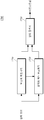
- FIG. 1 is an exemplary diagram showing a block for encoding a motion vector according to an embodiment of the present invention
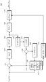
- FIG. 2 is a block diagram schematically illustrating a motion vector encoding apparatus according to an embodiment of the present invention
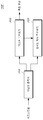
- FIG. 3 is a block diagram schematically illustrating a motion vector decoding apparatus according to an embodiment of the present invention.
- FIG. 4 is a flowchart illustrating a motion vector encoding method according to an embodiment of the present invention.
- FIG. 5 is a flowchart illustrating an embodiment of a motion vector encoding method according to an embodiment of the present invention
- FIG. 6 is a flowchart illustrating a process of selecting a candidate motion vector set according to an embodiment of the present invention
- FIG. 7 is a flowchart illustrating a process of selecting a predictive motion vector according to an embodiment of the present invention.
- FIG. 8 is a flowchart illustrating a process of determining whether an optimal predictive motion vector is predictable according to an embodiment of the present invention
- FIG. 9 is a flowchart illustrating a process of encoding a current motion vector using an optimal predictive motion vector according to an embodiment of the present invention.
- FIG. 10 is a flowchart illustrating a process of encoding a current motion vector using a default predicted motion vector according to an embodiment of the present invention
- FIG. 11 is a flowchart illustrating a process of performing third encoding according to an embodiment of the present invention.
- FIG. 12 is an exemplary diagram for explaining a case of collecting and encoding a motion vector prediction mode and the number of motion vector prediction modes according to an embodiment of the present invention
- FIG. 11 is a flowchart illustrating a motion vector decoding method according to an embodiment of the present invention.
- FIG. 12 is a flowchart illustrating a specific implementation of a motion vector decoding method according to an embodiment of the present invention
- FIG. 13 is a flowchart illustrating a process of determining a default predicted motion vector as a predicted motion vector for a current motion vector according to an embodiment of the present invention
- FIG. 14 is a flowchart for explaining a motion vector decoding method according to another embodiment of the present invention.
- FIG. 15 is a block diagram schematically illustrating a video encoding apparatus according to an embodiment of the present invention.
- 16 is an exemplary diagram illustrating a specific implementation of an image encoding device according to an embodiment of the present invention.
- FIG. 17 is a block diagram schematically illustrating an image decoding apparatus according to an embodiment of the present invention.
- FIG. 18 is an exemplary view illustrating a specific implementation of an image decoding apparatus according to an embodiment of the present invention.
- the video encoding apparatus, the video decoding apparatus, the motion vector encoding apparatus, and the motion vector decoding apparatus include a personal computer (PC), a notebook computer, a personal digital assistant (PDA), and a portable multimedia player (PMP).
- PC personal computer
- PDA personal digital assistant
- PMP portable multimedia player
- PSP Portable Multimedia Player
- PSP PlayStation Portable
- PSP Mobile Communication Terminal
- the present invention refers to various apparatuses including various programs for decoding or various programs for encoding or decoding motion vectors, a memory for storing data, a microprocessor for executing and operating programs, and the like.
- an image encoded in a bitstream by an image encoding apparatus or a motion vector encoding apparatus may be real-time or non-real-time, through a wired / wireless communication network such as the Internet, a local area wireless communication network, a wireless LAN network, a WiBro network, a mobile communication network, or the like. It may be transmitted to an image decoding apparatus or a motion vector decoding apparatus through a communication interface such as a universal serial bus (USB), so that the image or motion vector may be restored and reproduced.
- a wired / wireless communication network such as the Internet, a local area wireless communication network, a wireless LAN network, a WiBro network, a mobile communication network, or the like.
- a communication interface such as a universal serial bus (USB)
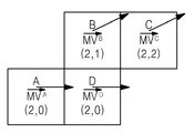
- FIG. 1 is an exemplary diagram illustrating a block for encoding a motion vector according to an embodiment of the present invention.
- block D is a "current block” corresponding to a motion vector to be encoded
- blocks A, B, and C are “near blocks” for block D.
- MV A , MV B , MV C And MV D Is a motion vector (MV) of blocks A, B, C, and D, and each is a horizontal component (MV).
- vertical components MV A y , MV B y , MV C y And MV D y Is defined as having
- the motion vector MV of the block D which is the current block D Is called the current motion vector.
- the predicted motion vector (PMV D ) for the current motion vector is a motion vector (MV A , MV B and MV C ) of neighboring blocks (block A, block B, block C ). It can be seen that it is calculated as a variable of a specific function (F ()).
- the predicted motion vector (PMV D ) for the current motion vector is calculated by using a function for calculating a median Median as a specific function F (). That is, the predicted motion vector PMV D for the current motion vector is obtained as the median Median for the motion vectors MV A , MV B and MV C of the neighboring blocks (blocks A, B, and C ). will be.
- the predicted motion vector PMV D with respect to the current motion vector MV D calculated in this manner is represented by Equation 2.
- the current motion vector (MV D) when determined that (PMV D), to be compressed by using the equation (3) using a predictive motion vector (PMV D) the soothing motion vector differential vector can be obtained a (DMV D differential motion Vector), the difference vector (DMV D) is encoded by a predetermined method a pre-defined, such as entropy encoding transmission do.
- Equation 2 As illustrated in FIG. 1, when the value of the current motion vector MV D is (2,0), using Equation 2 according to the conventional method of calculating the predicted motion vector PMV D through an intermediate value, The predicted motion vector PMV D becomes (2,1).
- the intermediate value is a predictive motion vector, so that both the encoding apparatus and the decoding apparatus know, so that it is not necessary to encode and transmit additional information about which motion vector is used as the predictive motion vector of the current motion vector. Encoding efficiency can be improved.
- the encoding apparatus is a concept including a motion vector encoding apparatus and an image encoding apparatus
- the decoding apparatus is a concept including a motion vector decoding apparatus and an image decoding apparatus. The motion vector encoding apparatus, the motion vector decoding apparatus, the image encoding apparatus, and the image decoding apparatus will be described in detail in the following process.
- the predicted motion vector PMV D calculated using the median value may be different from the actual current motion vector MV D.
- (2,1) which is the predicted motion vector (PMV D ) calculated using the median
- (2,0) which is the current motion vector (MV D )
- differential vector by using a third difference to the encoded ask (DMV D) vector (DMV D) is (0, -1).
- (2,0) which is the motion vector (MV A ) of the block A
- (2,0) which is the actual current motion vector (MV D )
- the differential signal (D DMV) to be encoded. That is, a prediction motion vector calculated using the median than using the (2,1) (PMV D), predict the (2,0) of the block A motion vector (MV A) the motion vector (PMV D ) Can reduce the amount of bits used to encode the difference vector (DMV D ) as (0,0).
- the motion vector MV A of the block A is converted to the predicted motion vector PMV D. It is impossible to use). If, additional to whether a motion vector (MV A) the block A predicted motion vector even with a (PMV D), used as MV A, MV B and MV C which motion vector is a predictive motion vector (PMV D) from Since information must be transmitted together, there is another problem in that it is not possible to guarantee whether the compression efficiency is improved by encoding additional information.
- the embodiment of the present invention proposes an efficient method for notifying the decoding apparatus of the selected prediction motion vector while improving encoding efficiency by selecting a more accurate prediction motion vector, thereby encoding additional information generated to inform the prediction motion vector. Also, the problem of bit increase due to the present invention will be solved.
- the motion vector prediction mode is skipped in the bitstream to be transmitted or stored, thereby improving the coding efficiency, but without knowing whether the motion vector prediction mode is omitted. Parsing is enabled to allow the decoding apparatus to operate stably.
- the motion vector prediction mode refers to a prediction mode of a motion vector for identifying how to predict the motion vector.
- a block (block A, block B, block C and block D) and a motion vector MV A , MV B , MV C and MV D corresponding thereto, which are exemplarily illustrated in FIG. 1, are generally used in the following process.
- the motion vectors MV A , MV B , MV C and MV D are illustrated as two-dimensional vectors having vertical and horizontal components, but this is for convenience of description and is not limited thereto. You can apply it as a vector.
- the neighboring blocks of the current block (block D) are shown as only three blocks A, B, and C according to spatial proximity in FIG. 1, this is for convenience of description, but is not limited thereto. There may be one or more peripheral blocks in the vicinity.
- the motion vector prediction mode includes a competitive prediction mode and a non-competing prediction mode.
- the competitive prediction mode refers to a mode in which there are several methods for predicting the current motion vector and competes with each other.
- the non-competitive prediction mode predicts only one method because there are not many methods for predicting the current motion vector. Say mode.
- the non-competitive prediction mode is determined as the motion vector prediction mode. This is because the encoding apparatus and the decoding apparatus can find the same predictive motion vector by themselves without further exchanging information for identifying which candidate motion vector is used as the predictive motion vector.
- the non-competitive prediction mode is the motion vector. Determined as the prediction mode. This is because the decoding apparatus obtains a predetermined default prediction motion vector by itself, such as a median value, and checks whether the default prediction motion vector is the same as the optimal prediction motion vector predicted through a predetermined process. This is because the decoding apparatus may know that the default prediction motion vector may be used as the prediction motion vector when the and optimal prediction motion vectors are the same, even if the decoding apparatus does not exchange additional information with the encoding apparatus.
- the decoding apparatus may know that the motion vector prediction mode is the non-competitive prediction mode by itself, and may use the default predicted motion vector as the prediction motion vector. Therefore, the case of determining the aforementioned non-competitive prediction mode is referred to as a non-competitive case.
- the decoding apparatus may use the default predicted motion vector as the predicted motion vector, and it may know for itself whether the current block corresponds to the non-competitive prediction mode. Therefore, the encoding apparatus does not need to further encode and transmit information indicating that the current block corresponds to the non-competitive prediction mode. That is, in this case, encoding and transmission of the motion vector prediction mode may be omitted.
- 'competition case' non-competitive case
- the decoding apparatus does not receive additional information from the encoding apparatus, which motion vector of the candidate motion vectors is used as the predicted motion vector. Since it is unknown, the encoding apparatus must additionally encode and transmit information about the same.
- the motion vector prediction mode corresponding to the contention case is referred to as a competitive prediction mode.
- the additional information indicates which motion vector of the candidate motion vectors is to be used as the prediction motion vector to recover the current motion vector. Tells.
- the additional information may be used by the decoding apparatus to reconstruct the current motion vector, using a motion vector (optimal predicted motion vector) selected according to a predetermined criterion or method among candidate motion vectors, or a predefined value such as an intermediate value.
- Information indicating whether to use a default predicted motion vector may be used. This information is a motion vector prediction mode.
- the optimal predicted motion vector only means a predicted motion vector of the current motion vector obtained according to a predetermined criterion or method, but does not mean that the predicted motion vector thus obtained is always an optimal predicted value.
- the additional information is to use the optimal predictive motion vector, it is the case that the decoding apparatus is able to predict the optimal predictive motion vector, so that the prediction is possible (that is, predictable), the motion vector prediction mode is 1 It can be expressed as a bit flag, but the flag can be expressed as '1'.
- the additional information is to use the default prediction motion vector, it is the case that the encoding apparatus determines that the optimum prediction motion vector cannot be predicted, and thus the prediction is not possible (that is, when it is not predictable). It can be expressed as a bit flag, but the flag can be expressed as '0'.
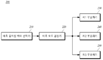
- FIG. 2 is a block diagram schematically illustrating a motion vector encoding apparatus according to an embodiment of the present invention.
- the motion vector encoding apparatus 200 may include a predictive motion vector selector 210, a motion vector prediction mode selector 220, a first encoder 230, and a second encoder ( 240 and the third encoder 250 may be configured.
- the predictive motion vector selector 210 selects a candidate motion vector set, which is a set of candidate motion vectors that can be used as a predictive motion vector, with respect to the current motion vector of the current block, and selects a predicted motion vector from the selected candidate motion vector set. .
- the method of selecting the predicted motion vector from the candidate motion vector set may vary.
- the candidate motion vector that minimizes the difference from the current motion vector in the candidate motion vector set may be selected as the predicted motion vector.
- the predicted motion vector selected from the candidate motion vector set by the predictive motion vector selector 210 is hereinafter referred to as an optimal predictive motion vector for convenience of description.
- the optimal prediction motion vector is defined as a specific example, and in the embodiment of the present invention, the optimal prediction motion vector is the prediction motion of the current motion vector obtained according to a predetermined criterion or method as described above. Means vector.
- the prediction mode determiner 220 determines whether the optimal predicted motion vector selected by the predictive motion vector selector 210 will be used for reconstructing the current motion vector or the default predicted motion vector by the motion vector decoding apparatus, and the result of the determination. In this case, one of the competitive prediction mode and the non-competitive prediction mode is selected to determine the motion vector prediction mode. In this case, when the motion vector prediction mode corresponds to the non-competitive prediction mode, the motion vector decoding apparatus may know for itself whether the block to be decoded corresponds to the non-competition prediction mode. Can raise.
- the prediction mode determiner 220 determines the non-competitive prediction mode as the motion vector prediction mode of the current block.
- the motion vector selected from the plurality of different candidate motion vectors that is, the optimal prediction motion vector is selected as the prediction motion vector as well as the case where the optimal prediction motion vector is the same as the default prediction motion vector. If there is no candidate motion vector, if there is only one candidate motion vector, there may be two or more candidate motion vectors but all may be the same.
- the candidate motion vector that can be used as the prediction motion vector in the prediction motion vector selector 210 does not exist (in this case, since there is no candidate motion vector that can be used as the prediction motion vector) 0 or 0). If one or both are the same, both the motion vector encoding apparatus 200 and the motion vector decoding apparatus will find the same optimal predicted motion vector, and the found optimal predicted motion vector is the default predicted motion vector. This is because
- the motion vector encoding apparatus 200 and the motion vector decoding apparatus share the same prediction motion vector by sharing a predetermined determination process in which the same result occurs even if the optimal prediction motion vector is selected through any prediction mode. You can choose.
- the difference vector which is the difference between the current motion vector and the predicted motion vector, is encoded by the first encoder 230.
- the first encoder 230 operates when the motion vector prediction mode is determined as the non-competitive prediction mode in the prediction mode determiner 220, and determines the default motion prediction vector as the prediction motion vector for the current motion vector, and determines the current motion vector.
- the difference vector of the predicted motion vector is calculated and the calculated difference vector is encoded.
- the second encoder 230 operates when the prediction mode determiner 220 determines that the motion vector prediction mode is the competitive prediction mode, and the prediction is determined according to the bit flag value of the motion vector prediction mode determined by the prediction mode determiner 220.
- a predefined default predicted motion vector e.g., motion vector prediction
- a motion vector i.e., an optimal predicted motion vector (e.g., when the bit flag value of the motion vector prediction mode is '1') or an intermediate value
- the bit flag value of the mode is '0')
- the difference vector calculated by encoding the difference vector between the current motion vector and the predicted motion vector is encoded.
- the third encoder 250 encodes the motion vector prediction mode of the blocks in which the motion vector prediction mode is determined as the competitive prediction mode by the prediction mode determiner 220 among the blocks in a predetermined unit (for example, a slice, a picture, etc.). do.
- the third encoder 250 separately encodes the motion vector prediction mode of the blocks in which the motion vector prediction mode is determined as the competitive prediction mode among the blocks in the predetermined unit, so that the motion vector decoding apparatus corresponds to the competitive prediction mode from the bitstream.
- the parsing process is performed independently of the decoding process of restoring the current motion vector or restoring texture information of the block.
- the third encoder 250 encodes a current motion vector, for example, a predetermined coding unit (for example, a slice unit or a picture unit, or less) existing above a coding unit (for example, a macroblock unit or a block unit).
- a current motion vector for example, a predetermined coding unit (for example, a slice unit or a picture unit, or less) existing above a coding unit (for example, a macroblock unit or a block unit).
- a coding unit for example, a macroblock unit or a block unit.
- a coding unit for example, a macroblock unit or a block unit.
- the upper unit may be a slice unit, but is not limited thereto and may be a larger unit than a slice unit such as a picture unit.
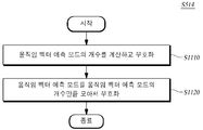
- the number of motion vector prediction modes of the blocks in which the motion vector prediction mode is determined as the competitive prediction mode among the blocks in the higher unit is determined.
- information that identifies i.e., the number of motion vector prediction modes to transmit or store
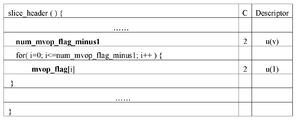
- number_mv_mode_flag_minus1 which is one less than the total number in FIG. 12
- Information identifying the number of information about the motion vector prediction mode that is, the bit flag indicating the motion vector prediction mode
- bit values of the bit flag may be listed, and FIG.
- the third encoder 250 identifies information for the number of motion vector prediction modes and moves by that number. While information on the prediction mode vector may be encoded using an encoding technique such as entropy encoding, or compression encoded in a variety of lossless compression scheme, it may still transmit without compression.
- the difference vector encoded by the first encoder 230 or the second encoder 240 is inserted into the bitstream, and the motion prediction mode encoded by the third encoder 250 is also inserted into the bitstream.
- a difference vector encoded by a multiplexer and a coded motion prediction mode may be inserted into the bitstream.
- the motion prediction mode encoded by the third encoder 250 when it is inserted into the bitstream, it may be inserted before the difference vector is inserted in the bitstream, and may be inserted into different headers according to higher units. For example, if the upper unit is a slice unit, it may be inserted into a slice header. If the upper unit is a picture unit, it may be inserted into a picture header.
- the encoded bitstream is transmitted and decoded to the motion vector decoding apparatus through a transmission channel such as a wired, wireless or storage medium.
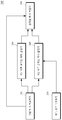
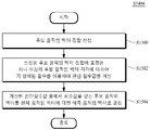
- FIG. 3 is a block diagram schematically illustrating a motion vector decoding apparatus according to an embodiment of the present invention.
- the motion vector decoding apparatus 300 includes a prediction mode decoder 310, a motion vector prediction mode determination and a differential vector decoder 320, and a first prediction motion vector determiner. 330, a second predicted motion vector determiner 340, and a motion vector reconstructor 350.
- the encoded motion vector prediction mode and the encoded difference vector which are encoded by the motion vector encoding apparatus 200 and inserted into the bitstream, are different from each other in advance between the motion vector encoding apparatus 200 and the motion vector decoding apparatus 300. It is decoded according to a predetermined unit. That is, the encoded motion vector prediction mode is decoded in an upper unit, and the encoded difference vector is decoded in a lower unit, that is, in a block unit.
- a motion vector prediction mode encoded from a bitstream and a coded differential vector are distinguished from each other by a demultiplexer, and the motion vector prediction mode encoded in a higher unit is a prediction mode decoder 310. ), And the encoded difference vector for each block is input to the motion vector prediction mode determination and the difference vector decoder 320. If the current block is encoded in the SKIP mode, there is no difference vector. Therefore, there is no encoded difference vector input to the motion vector prediction mode determination and the difference vector decoder 320.
- the prediction mode decoder 310 outputs a reconstructed motion vector prediction mode by decoding a coded motion vector prediction mode of blocks corresponding to a competitive prediction mode in an upper unit, and the output motion vector prediction mode is a storage medium such as a memory.
- the motion vectors determined by the motion vector prediction mode which are stored in the second prediction motion vector determiner 340 are sequentially read one by one each time the second prediction motion vector determiner 340 determines the prediction motion vector of each block. To decide.
- the reconstructed motion vector prediction mode includes bits indicating the number of motion vector prediction modes and bits indicating the number of motion vector prediction modes, and the prediction mode decoder 310 first determines the number of motion vector prediction modes.
- the number of motion vector prediction modes is determined by reading the indicating bits, the number of bits are read sequentially, and the bits indicating the number of motion vector prediction modes are read, the motion vector prediction mode is parsed, and the parsed motion vector prediction is parsed. Only bits indicating the mode are output and stored.
- the prediction mode decoder 310 parses the motion vector prediction modes corresponding to higher units classified in the bitstream through parsing when the motion vector prediction modes are represented as shown in FIG. 12 without additional compression such as entropy encoding.
- the motion vector prediction mode is restored. If entropy coding or other lossless compression coding is performed, the motion vector prediction mode is restored by decoding through an inverse process corresponding to each encoding method. In any case, the decoding process of the motion vector prediction mode is performed independently of a previous or subsequent decoding process (for example, decoding of the encoded difference vector or decoding of the encoded texture information).
- the differential vector decoder 320 determines whether the motion vector prediction mode of the current block to be decoded is a non-competitive prediction mode through a predetermined determination process shared between the motion vector encoding apparatus 200 and the motion vector decoding apparatus 300. If it is not in the non-competitive prediction mode, it is determined as the competitive prediction mode.
- the method of determining whether the differential vector decoder 320 determines whether the motion vector prediction mode of the current block is the non-competitive prediction mode is the same as or similar to the method of the prediction mode determiner 220 described above with reference to FIG. Description is omitted.
- the difference vector decoder 320 decodes the encoded difference vector to reconstruct the difference vector of the current block. At this time, the difference vector decoder 320 outputs (0,0) as a decoded difference vector when there is no encoded difference vector as in the encoding according to the SKIP mode.
- the difference vector decoder 320 informs the first predicted motion vector determiner 330 that the current block is the non-competitive prediction mode, and then selects the default predicted motion vector of the current block.
- the second prediction motion vector determiner 340 determines that the current block is the competitive prediction mode, and is determined according to the reconstructed motion vector prediction mode. The motion vector is determined as the predicted motion vector of the current block.
- the first predictive motion vector determiner 330 operates when the current block is in a non-competitive prediction mode, and uses the default predicted motion vector determined in a manner promised to the motion vector encoding apparatus 200 as the predicted motion vector for the current motion vector.
- the second prediction motion vector determiner 340 operates when the current block is in the competitive prediction mode, and is selected from among a set of candidate motion vectors selectable according to the motion vector prediction mode reconstructed by the prediction mode decoder 310, that is, The optimal predicted motion vector or the default predicted motion vector determined in a manner promised to the motion vector encoding apparatus 200 is determined as the predicted motion vector for the current motion vector.
- the second prediction motion vector determiner 340 should use the optimal prediction motion vector (for example, motion vector prediction). It should be determined whether the value of the bit flag of the mode is '1' or whether the default predicted motion vector should be used (eg, the value of the bit flag of the motion vector prediction mode is '0'). To this end, the second predictive motion vector determiner 340 sequentially reads the bits of the motion vector prediction mode, which are reconstructed and stored by the prediction mode decoder 310, one by one each time the predicted motion vector determiner of each block is determined. The motion vector determined by the vector prediction mode is determined as the predicted motion vector of each block.
- the optimal prediction motion vector for example, motion vector prediction. It should be determined whether the value of the bit flag of the mode is '1' or whether the default predicted motion vector should be used (eg, the value of the bit flag of the motion vector prediction mode is '0'). To this end, the second predictive motion vector determiner 340 sequentially reads the bits of the motion vector prediction mode, which are reconstructed and stored by
- the second predictive motion vector determiner 340 is the prediction motion vector of each block.
- a bit indicating a motion vector prediction mode is sequentially read, and the value of the read bit is checked to determine whether to use an optimal predicted motion vector or a default predicted motion vector. (For example, if the value of the read bit is '1', it is determined to use the optimal predictive motion vector, and if the value of the read bit is '0', the default prediction motion vector is determined.) .
- the motion vector reconstructor 350 may perform a prediction motion vector (optimum prediction motion vector or default prediction motion vector) and a differential vector decoder 320 determined by the first prediction motion vector determiner 330 or the second prediction motion vector determiner 340. ) Reconstructs the current motion vector of the current block by adding the reconstructed difference vector.
- a prediction motion vector optimum prediction motion vector or default prediction motion vector
- a differential vector decoder 320 determined by the first prediction motion vector determiner 330 or the second prediction motion vector determiner 340.
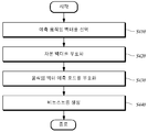
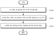
- FIG. 4 is a flowchart illustrating a motion vector encoding method according to an embodiment of the present invention.
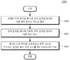
- the motion vector encoding apparatus 200 selects a predicted motion vector for the current motion vector according to the selected motion vector prediction mode among the plurality of motion vector prediction modes (S410), and encodes a difference vector between the current motion vector and the selected predicted motion vector.
- the motion vector prediction mode is encoded according to the selected motion vector prediction mode in operation S430, and a bitstream including the encoded difference vector and the encoded motion vector prediction mode is generated and output in operation S440.
- the motion vector encoding apparatus 200 encodes the motion vector prediction mode according to the selected motion vector prediction mode, wherein the motion vector encoding apparatus 200 and the motion vector decoding apparatus 300 perform the motion vector prediction mode of the current block. If it is assumed that the decision process for determining the P / S is shared, the motion vector prediction mode may be omitted without encoding the motion vector prediction mode when the motion vector prediction mode is the non-competitive prediction mode, and the motion vector prediction mode may be encoded only in the competitive prediction mode.
- the optimal prediction motion vector determined by the presence of a plurality of candidate motion vectors that are all the same or may be used is the default. If it is the same as the predictive motion vector, the motion vector encoding apparatus 200 and the motion vector decoding apparatus 300 may recognize that the same result occurs even if the optimal predictive motion vector is selected through any motion vector prediction mode. Therefore, in such a case, the motion vector encoding apparatus 200 and the motion vector decoding apparatus 300 share the same optimal prediction motion vector by sharing a predetermined determination process that the same result occurs even if the optimal prediction motion vector is selected through any prediction mode. Can be selected.
- the motion vector encoding apparatus 200 and the motion vector decoding apparatus 300 can determine whether to store (or transmit) the motion vector prediction mode by sharing a predetermined determination process, the non-competitive prediction mode is used. Since the difference vectors generated and encoded using the determined predicted motion vector may be identical, the motion vector encoding apparatus 200 and the motion vector decoding apparatus 300 may determine default predicted motion vectors determined in a mutually promising manner. It is selected as the predicted motion vector for the current motion vector.
- the motion vector encoding apparatus 200 selects a default prediction motion vector determined in a preset manner as a prediction motion vector for the current motion vector.
- the motion vector encoding apparatus 200 determines whether to use the optimal motion prediction vector or the default prediction motion vector as the prediction motion vector. do. To this end, the motion vector encoding apparatus 200 selects one candidate motion vector from among a plurality of candidate motion vectors as a prediction motion vector (ie, an optimal prediction motion vector) of the current motion vector by using a predetermined method. Through the same process, whether the motion vector decoding apparatus 300 can select the same motion vector as the optimal prediction motion vector selected by the motion vector encoding apparatus 200 as the optimal prediction motion vector, that is, the motion vector encoding apparatus 200 The motion vector decoding apparatus 300 determines whether the optimal prediction motion vector selected in FIG.
- a value indicating a predictable mode may be assigned to a bit representing the motion vector prediction mode (eg, For example, '1') is selected, and an optimal predicted motion vector is selected as the predicted motion vector for the current motion vector.
- a value indicating a non-predictable mode may be assigned to a bit representing the motion vector prediction mode (for example, For example, '0') is selected, and a default predicted motion vector is selected as the predicted motion vector for the current motion vector.
- the motion vector encoding method according to an embodiment of the present invention described above with reference to FIG. 4 may be embodied as shown in FIG. 5.
- FIG. 5 is a flowchart illustrating an embodiment of a motion vector encoding method according to an embodiment of the present invention.
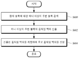
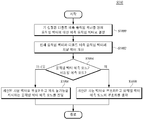
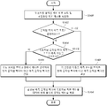
- the motion vector encoding apparatus 200 selects a candidate motion vector set for a current motion vector of a current block (S500), selects an optimal predicted motion vector from the selected candidate motion vector set (S502).
- the motion vector prediction mode is selected to determine whether the motion vector prediction mode is the non-competitive prediction mode by selecting a motion vector prediction mode of the current block.
- the current motion vector is encoded using the default prediction motion vector (S510).
- the motion vector encoding apparatus 200 determines whether there are remaining blocks in which all of the blocks in the higher unit of the block have not been performed in steps S500 to S510 (S512), and if there are remaining blocks, step S500.
- step S500 the procedure of steps S500 to S510 is performed on the remaining blocks, and when there is no remaining block, a third encoding is performed to encode a motion vector prediction mode for a block within a higher unit (S514).
- the motion vector encoding apparatus 200 inserts and outputs the current motion vector (that is, the difference vector) encoded in step S508 or S510 and the motion vector prediction mode encoded in step S514 into the bitstream.
- the motion vector encoding apparatus 200 determines whether the motion vector prediction mode is a non-competitive prediction mode according to a predetermined criterion shared with the motion vector decoding apparatus 300 in advance (or may skip the encoding accordingly).
- a predetermined criterion shared with the motion vector decoding apparatus 300 in advance (or may skip the encoding accordingly).
- Judge whether the encoding of the motion vector prediction mode can be omitted, that is, whether the motion vector prediction mode is the non-competitive prediction mode is determined by sharing the predetermined determination process between the motion vector encoding apparatus 200 and the motion vector decoding apparatus 300. In this case, it may be determined by determining whether the motion vector prediction mode corresponds to a case where it is possible to know which motion vector prediction mode to use without exchanging information on the motion vector prediction mode.
- the optimal prediction motion vector selected therefrom is the default prediction motion vector. Is the same as the non-competitive prediction mode. Therefore, whether the encoding of the motion vector prediction mode can be omitted, that is, whether the motion vector prediction mode is the non-competitive prediction mode, is generated and encoded by the difference vector and the optimal prediction motion vector generated and encoded by the default predictive motion vector. It is judged by the condition that it is known that the difference vectors are the same. Since it has been described above with reference to FIG. 2, a detailed description thereof will be omitted.
- step S504 When it is determined in step S504 that the motion vector prediction mode is a non-competitive prediction mode, or in step S506, when the motion vector decoding apparatus 300 cannot predict the optimal predicted motion vector selected in step S502, the motion vector encoding apparatus in step S514 ( 200 does not encode the motion vector prediction mode. However, if it is determined in step S506 that the motion vector prediction mode is the non-competitive prediction mode, and in step 506, the motion vector decoding apparatus 300 can predict the optimal predicted motion vector selected in step S502, the motion vector encoding apparatus (step S514). 200 encodes a motion vector prediction mode of the block.
- the motion vector encoding apparatus 200 collects and encodes motion vector prediction modes of blocks corresponding to the contention prediction mode in a block of an upper unit instead of a block unit. To this end, the motion vector encoding apparatus 200 may determine the motion vector prediction mode of the block corresponding to the competitive prediction mode among the blocks in the higher unit by the number of motion vector prediction modes (for example, bits indicating the same) and the number thereof.
- a motion vector prediction mode (eg, a bit representing it) is encoded, which may be encoded without compression or encoded using lossless compression encoding.
- the motion vector encoding apparatus 200 collects and encodes the motion vector prediction modes of the blocks corresponding to the competitive prediction mode among the blocks in the higher unit, the motion vector encoding apparatus 200 determines whether there is a remaining block in the higher unit through step S512, and Steps S500 to S512 are performed on all blocks in a unit to obtain a motion vector prediction mode of a block corresponding to a competitive prediction mode in all blocks in a different unit, and then encoded in step S514.
- the encoded difference vector and the motion vector prediction mode encoded in step S512 are inserted as syntax of the bitstream, respectively.
- the bitstream is transmitted to the motion vector decoding apparatus 300 through a transmission channel such as a wired, wireless or storage medium.
- step S500, step S502, step S506, step S508, and step S510 of the above-described steps will be described in detail with reference to FIGS. 6, 7, 8, 9, and 12 through FIG. 5.
- FIG. 6 is a flowchart illustrating a process of selecting a candidate motion vector set according to an embodiment of the present invention.
- operation S500 of selecting a candidate motion vector set searching for one or more neighboring blocks with respect to the current block in operation S600 and movement of the searched one or more neighboring blocks is performed.
- the candidate motion vector set selected in the above-described candidate motion vector set selection step (S500) is a block A, a block, which is a neighboring block at the left, top, and right upper sides of the block D, which is the current block.
- ⁇ MV A , MV B , MV C ⁇ consisting of motion vectors of B and block C.
- the candidate motion vector set may select more various motion vectors as a set of candidate motion vectors (candidate motion vector sets) according to an implementation method or needs.
- the motion vector of the same position block of the picture previously existing on the time axis or the motion vector of the block located on the upper left side on the spatial axis may be used as the candidate motion vector.
- another motion vector eg, an average value or a median value of several motion vectors selected using these motion vectors may be included.
- step S600 may include one or more first blocks at the same position as the current block in one or more of a picture that exists before and a picture that exists after; And one or more of one or more second blocks at positions adjacent to the current block on the spatial axis as one or more neighboring blocks.
- Step S602 further includes: each motion vector in the one or more first blocks; Each motion vector in the one or more second blocks; And an average or median value for one or more of each motion vector in the first block and each motion vector in the second block; One may be calculated as a motion vector of at least one neighboring block found.
- the above-described candidate motion vector set may be defined in various ways on the premise that the encoding apparatus 200 and the decoding apparatus 300 know in advance.
- the candidate motion vectors may be configured with only the candidate motion vectors having different values.
- FIG. 7 is a flowchart illustrating a process of selecting a predicted motion vector according to an embodiment of the present invention.
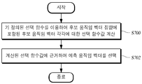
- operation S502 at least one candidate motion vector included in a set of candidate motion vectors selected by using a predefined selection function between the encoding apparatus 200 and the decoding apparatus 300. Calculating a selection function value for each (S700); And selecting one candidate motion vector as an optimal prediction motion vector based on the calculated selection function values (S702).
- selection function value may include a bit amount required to encode a difference vector with a current motion vector for each of one or more candidate motion vectors included in the selected candidate motion vector set; A magnitude of the difference vector from the current motion vector for each of the one or more candidate motion vectors included in the selected candidate motion vector set; And an amount of bits required to encode the motion vector prediction mode; It may also include one or more of these, or a combination of one or more of them.
- bit amount of the difference vector is used as the selection function value, in step S702 described above, for example, the bit amount required to encode the difference vector for each of one or more candidate motion vectors included in the selected candidate motion vector set is determined.
- the candidate motion vector which is the minimum value among the calculated bit amounts, may be selected as the optimal prediction motion vector.
- the predicted motion vector selection step (S502) in addition to the method of selecting the optimal predicted motion vector based on the above-described bit amount based on the selection function value, one of one or more candidate motion vectors included in the selected candidate motion vector set.
- the optimal predicted motion vector may also be selected using a rate-distortion optimization method that considers the amount of bits required for encoding when a motion vector is selected and the reconstruction quality to be generated.
- the Lagrangian Cost function in Equation 4 may be used as a selection function for selecting an optimal prediction motion vector.
- J is the Lagrange cost
- D is the error between the original and reconstructed images
- ⁇ is the Lagrange multiplier
- R H is the amount of bits required to encode the motion vector prediction mode
- R M is the amount of bits required to encode the difference vector of the current motion vector.
- J, D, R H , and R M are all defined according to n indicating a picture number where a current block is located and k indicating a block number. Therefore, it can be selectively applied in picture or block units.
- R H in Equation 4 is the amount of bits required for motion vector prediction mode encoding
- R M is a difference vector for the encoded current motion vector.
- the calculation method depends on the motion vector prediction mode. That is, when the motion vector prediction mode indicates that the decoding apparatus 300 cannot predict the optimal predicted motion vector, R M is a predicted motion vector generated by a predefined default method such as a median calculation. In other words, it is the amount of bits required to encode the difference vector between the default predicted motion vector and the current motion vector.
- R M is the amount of bits required to encode the difference vector between the selected optimal predicted motion vector and the current motion vector. .
- Equation 5 may also be used to select the optimal predicted motion vector. Equation 5 is expressed by assuming that the current motion vector of the current block to be encoded is MV D , which is the motion vector of block D in FIG. 1.
- PMV enc is the selected optimal prediction motion vector
- PMVC is one element (motion vector) belonging to the candidate motion vector set CS, which is a set of candidate motion vectors selectable as the prediction motion vector of the current motion vector MV D.
- h () is a selection function for selecting a predicted motion vector that is optimal for differentially encoding the current motion vector MV D from the predicted motion vector.
- a bit amount required to differentially encode a current motion vector is used, or a bit amount required to differentially encode a current motion vector and a bit amount required to encode a motion vector prediction mode. Can be used.
- the size of the difference vector which is the difference between the current motion vector and the predicted motion vector, may be used instead of the actual amount of bits to simplify the calculation.
- the definition of the selection function h () may be defined and used in various ways on the premise that the motion vector encoding apparatus 200 and the motion vector decoding apparatus 300 know in advance.
- one candidate motion vector (PMVC) that optimizes the selection function h () is optimized from the candidate motion vector set (CS) that includes the candidate motion vector that is a candidate of the prediction motion vector. It can be selected as a vector (PMV enc ).
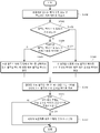
- FIG. 8 is a flowchart illustrating a process of determining whether an optimal predictive motion vector is predictable according to an embodiment of the present invention.
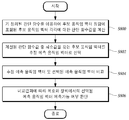
- the determination of whether the optimal prediction motion vector is predictable may be included in a candidate motion vector set selected using a predetermined determination function between the encoding apparatus 200 and the decoding apparatus 300.
- Calculating a decision function value for each of the one or more candidate motion vectors (S800); Selecting one candidate motion vector of the one or more candidate motion vectors as an estimated prediction motion vector for the current motion vector based on the calculated determination function value (S802); Comparing the selected estimated predicted motion vector and the selected optimal predicted motion vector (S804); And determining whether the selected optimal predicted motion vector is predictable by the decoding apparatus 300 according to the comparison result (S806).
- Determining whether the above-described predicted motion vector is predictable (S506) is described again using the expression in Equation 5, using the optimal predicted motion vector PMV enc selected in the previous predicted motion vector selection step S502.
- the difference vector calculated according to the above-described method, a finite number of candidate motion vectors that can be candidates for the predictive motion vector, a reference picture to be used for motion compensation, information of neighboring blocks already reconstructed, and motion compensation for pixel values.
- the residual signal it is determined whether the optimal predicted motion vector selected in the previous step S502 is predictable by the motion vector decoding apparatus 300.
- DMV D MV D -PMV enc
- PMV dec which is an estimated predicted motion vector, is found by using a predetermined decision method such as Equation (6).
- the determination function g () is determined by the motion vector encoding apparatus 200, and the motion vector decoding apparatus 300 determines the optimal predicted motion vector by using the information of the difference vector and the neighboring blocks which have already been reconstructed.
- the motion vector encoding apparatus 200 determines whether the PMV enc can be predicted. This determination function g () is also used when the motion vector decoding apparatus 300 predicts the predicted motion vector.
- the determination function g () may be defined in various ways under the assumption that the motion vector encoding apparatus 200 and the motion vector decoding apparatus 300 know the definition in advance, and specific embodiments of the determination function g () may be defined. Will be described later.
- the motion vector encoding apparatus 200 calculates in advance PMV dec which is an estimated predicted motion vector to be found by the motion vector decoding apparatus 300, and then DMV which is the difference vector provided by the motion vector decoding apparatus 300.
- PMV dec which is an estimated predicted motion vector to be found by the motion vector decoding apparatus 300
- DMV which is the difference vector provided by the motion vector decoding apparatus 300.
- the motion vector decoding apparatus 300 may determine the motion vector encoding apparatus 200.
- the motion vector encoding apparatus 200 determines that the optimal predicted motion vector PMV enc directly selected by the motion vector 200 is equal to the estimated predicted motion vector PMV dec estimated by the motion vector decoding apparatus 300. It is determined that the prediction of the optimal predicted motion vector PMV enc in the vector decoding apparatus 300 is possible, and in other cases, the prediction is impossible.
- the motion vector encoding apparatus 200 may determine between the optimal predicted motion vector PMV enc directly selected by the motion vector and the estimated predicted motion vector PMV dec estimated by the motion vector decoding apparatus 300. When the difference is smaller than the predetermined boundary value, it may be determined that the prediction of the optimal predicted motion vector PMV enc in the motion vector decoding apparatus 300 is possible, and in other cases, the prediction may be determined to be impossible. .
- Another example of a method for determining whether the optimal predicted motion vector PMV enc is predictable by the motion vector decoding apparatus 300 is as follows.
- the optimal predicted motion vector PMV enc and the estimated predicted motion may occur. Even if the vectors PMV dec are not equal, the motion vector decoding apparatus 300 determines that the optimal predicted motion vector PMV enc can be predicted using the estimated predicted motion vector PMV dec , and other than that. In this case, it is determined that it cannot be predicted.
- the motion vector decoding apparatus 300 estimates the estimated predicted motion vector (PMV dec ).
- the selected estimated prediction motion vector and the selected optimal prediction motion vector are equal to or less than a predetermined boundary value. If so, the selected optimal predicted motion vector may be determined to be predictable by the motion vector decoding apparatus 300.
- the decoding apparatus 300 may determine that the selected optimal predicted motion vector is predictable.
- the motion vector encoding apparatus 200 uses the determination function (g () in Equation 6) defined between the motion vector encoding apparatus 200 and the motion vector decoding apparatus 300 to determine the determination function.
- a value is calculated (S800), and a candidate motion vector having a minimum decision function value is selected as the estimated prediction motion vector (PMV dec ) based on the calculated decision function value (S802). Thereafter, the estimated predicted motion vector PMV dec is compared with the optimal predicted motion vector PMV enc (S804), and finally it is determined whether it is predictable (S806).
- the predefined determination function between the motion vector encoding apparatus 200 and the motion vector decoding apparatus 300 may be realized in various forms.
- a function using template matching (TM) and a function using boundary pixel matching (BM) can be used.
- a template matching pixel index set is an index indicating a relative position of selected pixels based on a given designated block position. It can be defined as a set, for example, the position of the surrounding M pixels adjacent to the left, top left and top of the designated block. Of course, other methods are possible if necessary. In general, if the number of pixels indicated by the TMS is more accurate, more accurate matching is possible.
- the template matching method includes, after selection of all candidate predictive motion vector sets (CS) selectable as the predictive motion vectors, the pixels indicated by the TMS for the reference block designated by each candidate motion vector in the selected candidate predictive motion vector set;
- the difference between the pixels indicated by the TMS for the current block is calculated by using Equation 7 (an embodiment of Equation 6), and the matching error is calculated according to each candidate motion vector, which has the lowest matching error. It is selected as the estimated prediction motion vector (PMV dec ) mentioned above.
- (PMVC + DMV) in f (PMVC + DMV, i) represents the pixel position indicated by index i around the reference block in the reference picture indicated by index i (included in TMS), and f (PMVC + DMV , i) means the pixel value at this position.
- C (i) means a pixel value around the current block indicated by the index i.
- DMV) which is an embodiment of the determination function, predicts the motion of the candidate motion vector PMVC, which is one element of the candidate motion vector set CS, to the difference vector DMV D provided by the motion vector encoding apparatus 200.
- the corrected block obtained by motion compensation of the block is provided.
- the sum of squared errors (Sum of Squared Error) is used in Equation 7, but other methods such as a sum of absolute difference (SAD) may be possible depending on the application.
- the estimated predicted motion vector PMV dec denotes a candidate motion vector PMVC that minimizes g (PMVC
- pixels indicated by a template matching pixel index (TMS) for the reference block designated by each of the one or more candidate motion vectors included in the selected candidate motion vector set, and the current are displayed.
- TMS template matching pixel index
- Predefined determination by calculating the pixel value difference of the pixels indicated by the template matching pixel index for the block, and calculating the matching error for each of the one or more candidate motion vectors as a determination function value based on the calculated pixel value difference. You can calculate the value of the judgment function by executing the function.
- boundary matching pixel index set BMS Boundary Matching Index Set
- BM boundary pixel matching
- the motion vector decoding apparatus 300 After selecting all the candidate motion vector sets CS selectable as the predictive motion vectors, to determine which candidate motion vectors PMVC among the candidate motion vector sets CS are the most optimal, the current reconstructed ones encoded with motion compensation In order to calculate how smoothly a block is connected to its neighbors at the block boundary, boundary pixel matching is performed to determine a candidate motion vector (PMVC) from the candidate motion vector set (CS) that minimizes the boundary pixel matching matching error. The estimated prediction motion vector PMV dec is selected. This is called a predicted motion vector selected by the motion vector decoding apparatus 300.
- the process is calculated as PMVC + DMV using the candidate motion vector PMVC, which is one element of the candidate motion vector set CS, and the difference vector DMV determined by the motion vector encoding apparatus 200.
- PMVC candidate motion vector
- DMV difference vector determined by the motion vector encoding apparatus 200.
- a prediction motion vector for generating a reconstructed block having the highest boundary matching with the reconstructed pixels around the block is determined.
- the matching error of each candidate motion vector is calculated as the sum of squares of the difference values.
- SAD sum of absolute difference
- C (i) is a candidate motion vector calculated as PMVC + DMV using the candidate motion vector PMVC, which is one element of the candidate motion vector set CS, and the DMV determined by the motion vector encoding apparatus 200.
- f (i) means a pixel value immediately adjacent to the pixel designated by the index i of the BMS among the boundary pixels in the neighboring block adjacent to the current block.
- Equation 8 a boundary pixel matching error is calculated for each candidate motion vector PMVC in the candidate motion vector set CS, and among the candidate motion vectors generating the least matching error, the estimated motion vector ( PMV dec ). This is called a predicted motion vector selected by the motion vector decoding apparatus 300.
- step S800 a candidate motion vector calculated using the difference vector determined by the motion vector encoding apparatus 200 and the candidate motion vector for each of one or more candidate motion vectors included in the selected candidate motion vector set is included.
- the index of the boundary matching pixel index set (BMS) among the reconstructed pixels of the current block reconstructed by adding the value of the designated reference block and the residual signal according to the motion compensation calculated by the motion vector encoding apparatus 200 is designated.
- the decision function value may be calculated by performing a predetermined decision function.
- the motion vector encoding apparatus 200 may determine an estimated prediction motion vector having a minimum matching error determined according to a predetermined determination method such as template matching or boundary pixel matching. PMV dec ).
- step S804 the selected estimated prediction motion vector PMV dec is compared with the optimal prediction motion vector PMV enc selected in step S502.
- the motion vector decoding apparatus 300 may determine the optimal predicted motion vector of the current motion vector of the current block. It can be determined that can be predicted, otherwise it can not be predicted.
- the motion vector decoding apparatus 300 can predict the optimal prediction motion vector of the current motion vector of the current block. It may be.
- FIG. 9 is a flowchart illustrating a process of encoding a current motion vector using an optimal predictive motion vector according to an embodiment of the present invention.
- encoding a current motion vector using an optimal predicted motion vector may include determining the selected optimal predicted motion vector as a predicted motion vector for the current motion vector (S900); Calculating a difference vector between the current motion vector and the selected optimal predicted motion vector (S902); And (S904) or the like, by encoding the calculated difference vector, encoding the current motion vector and transmitting a motion vector prediction mode indicating the predictability to the third encoder 250.
- FIG. 10 is a flowchart illustrating a process of encoding a current motion vector using a default predicted motion vector according to an embodiment of the present invention.
- the step S510 of encoding the current motion vector using the default prediction motion vector may include determining a preset default prediction motion vector as a prediction motion vector for the current motion vector (S1000); Calculating a difference vector between a current motion vector and a preset default predicted motion vector (S1002); Determining whether the motion vector prediction mode in operation S504 is a non-competition prediction mode (S1004); When the motion vector prediction mode is not the non-competitive prediction mode, that is, the omission of the motion vector prediction mode is not possible, the motion vector prediction mode encoding the current motion vector and indicating the unpredictability by encoding the calculated difference vector may include a third encoder.
- the motion vector prediction mode is the non-competitive prediction mode, that is, when it is possible to omit the motion vector prediction mode, encoding the current motion vector by encoding the calculated difference vector and omitting the encoding of the motion vector prediction mode (S1008), etc. It includes.
- the preset default predicted motion vector in step S1002 is a median of the motion vectors of one or more neighboring blocks adjacent to the current block, and is preset between the motion vector encoding apparatus 200 and the motion vector decoding apparatus 300. do.
- FIG. 11 is a flowchart illustrating a process of encoding a motion vector prediction mode according to an embodiment of the present invention.
- the motion vector prediction mode may be encoded by calculating and encoding the number of motion vector prediction modes existing in an independent coding unit corresponding to a predetermined non-independent coding unit in which a motion vector exists. Step S1110; And collecting and encoding the motion vector prediction mode existing in the independent coding unit corresponding to the upper portion of the predetermined non-independent coding unit in which the motion vector exists (S1120).
- FIG. 12 is an exemplary diagram for describing a case of collecting and encoding the number of motion vector prediction modes and the motion vector prediction modes according to an embodiment of the present invention.
- a method of collecting and encoding a motion vector prediction mode and a number of motion vector prediction modes present in a higher layer in higher units such as a slice unit that is an independent coding unit corresponding to a higher layer rather than a block unit in which a motion vector is encoded. Able to know.
- FIG. 13 is a flowchart illustrating a motion vector decoding method according to an embodiment of the present invention.
- the motion vector decoding apparatus 300 decodes a bitstream, restores a difference vector between a current motion vector and a predicted motion vector, and a motion vector prediction mode of the current motion vector (S1300), and determines the motion vector prediction mode.
- a prediction motion vector of the current motion vector is selected based on the selected motion vector (S1302), and the current motion vector is restored using the selected prediction motion vector (S1304).
- the motion vector encoding apparatus 200 may selectively convert a separately encoded motion vector prediction mode and a difference vector from each other by a predetermined predetermined independent or previously promised between the motion vector encoding apparatus 200 and the motion vector decoding apparatus 300. Decode according to non-independent units. That is, it is determined whether a motion vector prediction mode exists through a predetermined determination process between the motion vector encoding apparatus 200 and the motion vector decoding apparatus 300.
- the motion vector prediction mode is defined as the non-competitive prediction mode, and in step S1302, the prediction motion vector is selected as the default prediction motion vector. If it is determined in step S1300 that the motion vector prediction mode exists, a bit value indicating the motion vector prediction mode of the block is read from the motion vector prediction mode of the block corresponding to the competitive prediction mode in the higher unit reconstructed in step S1300. The motion vector indicated by this value is selected as the predicted motion vector of the corresponding block.
- the motion vector decoding apparatus 300 may determine that the bit value indicating the motion vector prediction mode is the competitive vector prediction mode but the unpredictable mode (for example, when the bit value is '0'). We then select a default predicted motion vector that is determined according to the promised scheme.
- the bit value indicating the motion vector prediction mode indicates the predictable mode while the motion vector prediction mode is the competitive prediction mode (for example, the bit value is '1').
- one candidate motion vector is selected from among a plurality of candidate motion vectors as a prediction motion vector of the current motion vector, that is, an optimal prediction motion vector by using a predetermined method.
- the predetermined method may be a method based on one of template matching and boundary pixel matching.
- FIG. 14 is a flowchart illustrating a specific implementation of a motion vector decoding method according to an embodiment of the present invention.
- the motion vector decoding apparatus 300 decodes a motion vector prediction mode encoded by the motion vector encoding apparatus 200 and an encoded difference vector (S1400); Determining whether a motion vector prediction mode exists (S1402); Determining whether the decoded motion vector prediction mode indicates predictable or unpredictable (S1404); If the decoded motion vector prediction mode indicates predictable, a selectable candidate motion vector set is selected as a predictive motion vector for reconstructing the current motion vector of the current block, and an optimal predictive motion vector is selected from the selected candidate motion vector set.
- Determining the selected optimal predicted motion vector as a predicted motion vector with respect to the current motion vector (S1406); If the motion vector prediction mode does not exist or the decoded motion vector prediction mode indicates unpredictable, determining a default predicted motion vector determined according to a preset method as a predicted motion vector for the current motion vector (S1408); And reconstructing the current motion vector of the current block by adding the predicted motion vector and the decoded difference vector determined in step S1406 or S1408 (S1410).
- the encoded difference vector in operation S1400 may be a difference vector between the current motion vector and the preset default predicted motion vector, or may be a difference vector between the current motion vector and the optimal predicted motion vector.
- 15 is a flowchart illustrating a process of determining a default predicted motion vector as a predicted motion vector with respect to a current motion vector according to an embodiment of the present invention.
- the default predicted motion vector is determined as the predicted motion vector for the current motion vector according to an embodiment of the present invention.
- Selecting a possible candidate motion vector set (S1500); Computing a determination function value for each of one or more candidate motion vectors included in the selected candidate motion vector set by using a determination function commonly defined by the motion vector encoding apparatus 200 and the motion vector decoding apparatus 300. (S1502); And selecting a candidate motion vector having a minimum value among the calculated determination function values as an optimal prediction motion vector, and selecting the selected optimal prediction motion vector as a prediction motion vector for the current motion vector (S1504).
- the optimal predicted motion vector determined by the motion vector decoding apparatus 300 as a predicted motion vector for the current motion vector is an estimated predicted motion estimated by the motion vector decoding apparatus 300 by the motion vector decoding apparatus 200. It may be equal to the vector PMV dec or may show a difference in a predetermined boundary value.
- the motion vector decoding apparatus 300 indicates a template matching pixel index set (TMS) for a reference block designated by each of one or more candidate motion vectors included in the selected candidate motion vector set. Compute the pixel value difference between the pixels indicated by the template matching pixel index and the pixel corresponding to the current block, and calculate a matching error for each of the one or more candidate motion vectors based on the calculated pixel value difference.
- TMS template matching pixel index set
- the motion vector decoding apparatus 300 calculates each of one or more candidate motion vectors included in the selected candidate motion vector set by using the difference vector determined by the motion vector encoding apparatus 200 and the corresponding candidate motion vectors.
- Boundary Matching Set (BMS) among the reconstructed pixels of the current block reconstructed by adding the reference block value designated by the candidate candidate motion vector and the residual signal according to the motion compensation calculated by the motion vector encoding apparatus 200 (BMS) A pixel value designated by an index within the pixel; And a matching error for each of the one or more candidate motion vectors, based on the difference between the pixel designated by the index of the boundary matching pixel index set among the boundary pixels in the neighboring block adjacent to the current block and the adjacent pixel value, as a determination function value. .
- 16 is a flowchart illustrating a motion vector decoding method according to another embodiment of the present invention.
- the motion vector decoding method provided by the motion vector decoding apparatus 300 may include a motion vector prediction mode encoded by the motion vector encoding apparatus 200 and a coded difference. Decoding the vector (S1600); Determining whether a motion vector prediction mode exists (S1602); Determining whether the decoded motion vector prediction mode indicates predictable or unpredictable (S1604); If the decoded motion vector prediction mode indicates predictable, a selectable candidate motion vector set is selected as a predictive motion vector for reconstructing the current motion vector of the current block, and an optimal predictive motion vector is selected from the selected candidate motion vector set.
- a motion vector prediction mode encoded by the motion vector encoding apparatus 200 and a coded difference. Decoding the vector (S1600); Determining whether a motion vector prediction mode exists (S1602); Determining whether the decoded motion vector prediction mode indicates predictable or unpredictable (S1604); If the decoded motion vector prediction mode indicates predictable, a selectable candidate motion vector set is selected as a predictive motion vector for reconstructing the current motion vector of the current block
- Determining the selected optimal predicted motion vector as a predicted motion vector for the current motion vector (S1606); If the motion vector prediction mode does not exist or the decoded motion vector prediction mode indicates unpredictable, determining a default predicted motion vector determined according to a preset method as a predicted motion vector for the current motion vector (S1608); Reconstructing the current motion vector of the current block by adding the predicted motion vector determined in step S1606 or step S1608 and the decoded difference vector (S1610); A normal decoding determination step (S1612) using the number of motion vector prediction modes; And an optional additional processing step (S1614) for abnormal decoding.
- a motion vector prediction mode of a block to be encoded or decoded independently and independently under the premise that the motion vector encoding apparatus 200 and the motion vector decoding apparatus 300 share a predetermined predetermined decision process. Can determine whether or not is a non-competitive prediction mode. Therefore, only the bits distinguishing between the predictable mode and the unpredictable mode are transmitted only when the motion vector prediction mode of the block is the competitive prediction mode. By omitting the encoding, the amount of bits required to encode the current motion vector can be greatly reduced.
- the motion vector encoding apparatus 200 determines whether the motion vector prediction mode of the block is the non-competitive prediction mode. That is, when an error occurs in a reconstructed motion vector of a previously decoded neighboring block and is reconstructed into a motion vector other than the motion vector used for encoding, whether the motion vector prediction mode of the block to be decoded is a non-competitive prediction mode. In the determination, an error may occur, which may cause a decoder crash.
- the motion vector decoding apparatus 300 reads the bit value of the reconstructed motion vector prediction mode to read the bit value. Accordingly, the predictable mode or the unpredictable mode is determined to determine the optimal predicted motion vector or the default predicted motion vector as the predicted motion vector for the current block.
- the bit value of the reconstructed motion vector prediction mode should not be read.
- the bit value of the motion vector prediction mode to be used in the block is abnormally used, the bit value becomes insufficient when the bit value of the motion vector prediction mode restored in the block is subsequently read. And the entire process of decoding the image may be stopped.
- a bit indicating a motion vector prediction mode that is, a bit indicating a predictable mode and / or Or bits indicating the number of motion vector prediction modes are encoded together and inserted into the bitstream in higher units such as slice units or picture units higher than the block units in which the motion vectors are determined.
- the motion vector decoding apparatus 300 parses an encoded motion vector prediction mode inserted into higher units from a bitstream and decodes independently of a decoding process performed in block units.
- the number of motion vector prediction modes obtained by acquiring the number of motion vector prediction modes and the number of blocks in which the motion vector prediction mode exists among the decoded blocks are different from each other. You can determine that an error has occurred and follow up. That is, the motion vector decoding apparatus 300 may determine whether an error occurs by using the number of motion vector prediction modes, and if it is determined that the error has occurred, reset the motion vector itself or track the error to restore the normal motion vector. You can try
- decoding the encoded motion vector prediction mode and the encoded difference vector It is calculated through the step S1402 of determining whether the motion vector prediction mode exists until all the blocks in the upper unit such as the slice and the number of motion vector prediction modes acquired in S1400 are sliced as a predetermined independent coding unit. If the number of motion vector prediction modes is different, it may be determined that the corresponding bitstream has not been normally decoded. If the corresponding bitstream is not normally restored, motion vector recovery may be attempted in various ways through an optional additional processing step (S1614) for abnormal decoding.
- the number of motion vector prediction modes delivered by the motion vector encoding apparatus 200 is calculated after all decoding processes for the upper unit (eg, a slice) are completed.
- the number of motion vector prediction modes is large, it may be assumed that all of the remaining motion vector prediction modes are ignored and none of the motion vector prediction modes exist.
- the number of motion vector prediction modes is smaller than the number of motion vector prediction modes calculated after the decoding process for the higher unit is finished, an error occurs in the stored (or transmitted) bitstream and thus cannot be normally restored. Since it means that it is not possible, the image may be restored by applying an error concealment method, ignoring the stored bitstream itself.
- FIG. 17 is a block diagram schematically illustrating a video encoding apparatus according to an embodiment of the present invention.
- the image encoding apparatus 1700 may include a texture encoder 1710, a motion vector encoder 1720, and a multiplexer 1730.
- the texture encoder 1710 predicts a current block according to a current motion vector of a current block to be encoded in an input image, encodes a residual block that is a difference between the current block, and a prediction block, and outputs an encoded texture.
- the texture encoder 1710 will be described in detail with reference to FIG. 18 in a later process.
- the motion vector encoder 1720 selects a motion vector prediction mode of one of the plurality of motion vector prediction modes, selects a prediction motion vector for the current motion vector according to the selected motion vector prediction mode, and selects a current motion vector and the selected prediction motion.
- the difference vector which is a difference between the vectors, is encoded, and the motion vector prediction mode is encoded according to the selected motion vector prediction mode to output the encoded difference vector and the encoded motion vector prediction mode.
- the motion vector encoder 1720 performs the same or similar function as that of the motion vector encoding apparatus 200 described above with reference to FIG. 2, a detailed description thereof will be omitted.
- the multiplexer 1730 generates and outputs a bitstream including an encoded texture, an encoded difference vector, and an encoded motion vector prediction mode.
- the slice is not a block unit into which the texture and the coded difference vector encoded in the bitstream are inserted.
- the video decoding apparatus may independently decode the encoded motion vector prediction mode.
- FIG. 18 is a diagram illustrating a specific implementation of an image encoding device according to an embodiment of the present invention.
- the above-described image encoding apparatus 1700 including the specific configuration of the texture encoder 1710 may be represented by the image encoding apparatus 1800 illustrated in FIG. 18.
- the texture encoder 1710 includes a predictor 1810, a subtractor 1820, a transformer 1830, a quantizer 1840, an encoder 1850, an inverse quantizer including a motion estimator 1812 and a motion compensator 1814. 1860, inverse converter 1870, adder 1880, and deblocking filter 1890.
- the predictor 1810 predicts the current block to generate and output the predicted block. That is, the predictor 1810 generates a predicted block having a predicted pixel value of each pixel by predicting a pixel value of each pixel of the current block to be encoded in the image. do.
- the predictor 1810 may include a motion vector estimator 1812 and a motion compensator 1814.
- the motion vector estimator 1812 is a block unit (eg, 16 ⁇ 16 block, 16 ⁇ 8 block, 8 ⁇ 16 block, 8 ⁇ 8 block, 8 ⁇ ) corresponding to the block mode or the preset block mode for the current block.
- the current motion vector is determined by estimating the motion vector of the current block with reference to one or more reference pictures (4 blocks, 4x8 blocks, 4x4 blocks).
- the current motion vector determined by the motion vector estimator 1812 is output to the motion vector encoder 1720, and the difference vector and the motion vector prediction mode are encoded by the motion vector encoder 1720.
- the motion vector estimator 1812 estimates the motion vector of the current block by using the reference picture to determine the current motion vector, and thus a detailed description thereof will be omitted.
- the motion compensator 1814 generates and outputs a prediction block of the current block by using the current motion vector output from the motion vector estimator 1812. That is, the motion compensator 1814 outputs a block indicated by the current motion vector in the reference picture as a prediction block.
- the subtractor 1820 subtracts the prediction block from the current block to generate a residual block. That is, the subtractor 1820 calculates a difference between the pixel value of each pixel of the current block to be encoded and the predicted pixel value of each pixel of the prediction block predicted by the predictor 1810 to obtain a residual signal in the form of a block. Creates a residual block with
- Converter 1830 and quantizer 1840 transform and quantize the residual block to output the quantized residual block. That is, the transformer 1830 and the quantizer 1840 transform the residual signal of the residual block into the frequency domain, convert each pixel value of the residual block into a transform coefficient, and quantize the residual block having the frequency coefficient. Quantization).
- the transformer 1830 is a residual using a variety of transformation techniques for transforming the image signal of the spatial axis to the frequency axis, such as a Hadamard transform, Discrete Cosine Transform Based Transform (DCT based Transform)
- DCT based Transform Discrete Cosine Transform Based Transform
- the signal can be converted into the frequency domain, and the residual signal converted into the frequency domain becomes a conversion coefficient.
- the quantizer 1840 may convert the transformed residual block into dead zone uniform threshold quantization (DZUTQ), a quantization weighted matrix, or an improved quantization technique. Can be quantized using DZUTQ), a quantization weighted matrix, or an improved quantization technique.
- the encoder 1850 encodes the residual block output from the quantizer 1840 and outputs an encoded texture. That is, the encoder 1850 scans the quantized frequency coefficients, transform coefficients, or residual signals of the residual block according to various scan methods such as zigzag scan to generate quantized transform coefficient sequences, transform coefficient sequences, or signal sequences, and entropy coding. Encoding is performed using various encoding techniques such as a technique.
- the encoded texture output from the encoder 1850 is generated and output as a bitstream in the multiplexer 1730 together with the encoded difference vector and the encoded motion vector prediction mode output from the motion vector encoder 1720.
- Inverse quantizer 1860 and inverse transformer 1870 inverse quantize and inverse transform the quantized residual block. That is, the inverse quantizer 1860 and the inverse transformer 1870 inversely quantize the quantized frequency coefficients of the angularized residual block to generate a residual block having transform coefficients, and inversely transform the inverse quantized residual block to convert pixel values. Generates a residual block, that is, a restored residual block.
- the inverse quantizer 1860 and the inverse converter 1870 may perform inverse transformation and inverse quantization using the above-described transformation scheme and quantization scheme inversely.
- the adder 1880 reconstructs the current block by adding the predicted block predicted by the predictor 1810 and the residual block reconstructed by the inverse transformer 1870.
- the deblocking filter 1890 deblocks and filters the restored current block and outputs the deblocked filter.
- the deblocking filtering refers to an operation of reducing block distortion generated by encoding an image in block units, and applying a deblocking filter to a block boundary and a macroblock boundary, or applying a deblocking filter only to a macroblock boundary or a deblocking filter. You can optionally use one of the methods that does not use.
- the transformer 1830 and the quantizer 1840 may be implemented as a first encoder and the encoder 1850 may be implemented as a second encoder, which should not be included in the texture encoder 1710. It may optionally be included depending on how it is implemented. That is, the residual signal output from the subtractor 1820 does not necessarily have to be transformed and quantized, and may perform only one of the transformed and quantized, and even both the transformed and quantized may be omitted. In this case, the inverse quantizer 1860 and the inverse transformer 1870 may also be selectively included depending on whether to perform the transformation and / or quantization. In addition, the deblocking filter 1890 is not necessarily included in the texture encoder 1710, and may be selectively included according to an implementation manner.
- the image encoded in the bitstream by the image encoding apparatus 1800 is real-time or non-real-time through a wired or wireless communication network such as the Internet, a local area wireless communication network, a wireless LAN network, a WiBro network, a mobile communication network, or the like.
- the image decoding apparatus may be transmitted to a video decoding apparatus to be described later through a communication interface such as a universal serial bus (USB), decoded by a video decoding apparatus to be described later, and restored and reproduced.
- a communication interface such as a universal serial bus (USB)
- 19 is a block diagram schematically illustrating an image decoding apparatus according to an embodiment of the present invention.
- the image decoding apparatus 1900 may include a demultiplexer 1910, a motion vector decoder 1920, and a texture decoder 1930.
- the demultiplexer 1910 extracts and outputs an encoded texture, an encoded difference vector, and an encoded motion vector prediction mode from the bitstream.
- the encoded texture is output to the texture decoder 1930, and the encoded difference vector and the encoded motion vector prediction mode are output to the motion vector decoder 1920.
- the demultiplexer 1910 may parse and extract a motion vector prediction mode encoded in an upper unit of a block unit such as a slice header or a picture header of a bitstream.
- the motion vector decoder 1920 decodes the coded difference vector and the coded motion vector prediction mode to reconstruct the difference vector and the motion vector prediction mode, and reconstructs the current motion vector of the current block based on the reconstructed motion vector prediction mode.
- the prediction motion vector is selected, and the reconstructed difference vector and the selected prediction motion vector are added to reconstruct the current motion vector. Since the motion vector decoder 1920 performs the same or similar functions as the motion vector decoding apparatus 300 described above with reference to FIG. 3, a detailed description thereof will be omitted.
- the texture decoder 1930 decodes the encoded texture to reconstruct the residual block, and adds the predicted block and the reconstructed residual block that predict the current block by using the current motion vector reconstructed by the motion vector decoder 1920. Restore and print the current block.
- a detailed implementation example of the texture decoder 1930 will be described with reference to FIG. 20 in a later process.
- FIG. 20 is an exemplary view illustrating a specific implementation of an image decoding apparatus according to an embodiment of the present invention.
- the above-described image decoding apparatus 1900 including the specific configuration of the texture decoder 1930 may be represented by the image encoding apparatus 2000 illustrated in FIG. 20.
- the texture decoder 1930 may include a decoder 2010, an inverse quantizer 2020, an inverse transformer 2030, a motion compensator 2040, an adder 2050, and a deblocking filter 2060. .
- the decoder 2010 decodes the encoded texture output from the demultiplexer 1910 to restore the quantized residual block.
- Inverse quantizer 2020 and inverse converter 2030 perform the same or similar functions as inverse quantizer 1860 and inverse converter 1870 described above with reference to FIG. However, in the case where the image encoding apparatus 1800 performs only one or none of transform and quantization of the residual block, the inverse quantizer 1860 and the inverse transformer 1870 may also perform only one or none accordingly. have.
- the motion compensator 2040 predicts the current block by using the reconstructed current motion vector output from the motion vector decoder 1930 and outputs a prediction block. That is, the motion compensator 2040 generates and outputs a block indicated by the current motion vector reconstructed from at least one reference picture as a prediction block.
- the adder 2050 adds the reconstructed residual block output from the inverse transformer 2030 and the predictive block output from the motion compensator 2040 to reconstruct and output the current block.
- the deblocking filter 2060 deblocks and filters the restored current block and outputs the deblocking filter.
- the motion vector prediction mode includes a competitive prediction mode and a non-competitive prediction mode.
- the competitive prediction mode the motion vector prediction mode indicating the unpredictability of the optimal prediction motion vector and the motion vector prediction mode indicating the predictability of the optimal prediction motion vector have been described.
- the optimal prediction motion vector means a prediction motion vector selected from a finite number of candidate motion vector sets according to a predetermined criterion or method, and does not mean that the prediction value of the selected prediction motion vector is always optimal. .
- the competitive prediction mode may be understood as a mode that can be used for encoding and / or decoding the current motion vector after selecting a prediction motion vector other than the default prediction motion vector according to a predetermined method.
- the prediction motion vector may be selected by a predetermined method from the plurality of candidate motion vector sets as described above.
- the motion vector closer to the current motion vector can be selected as the predictive motion vector, thereby minimizing the bit amount according to the encoding of the difference vector.
- the efficiency can be improved.
- the motion vector encoding apparatus 200 does not directly inform the motion vector decoding apparatus 300 to find the selected predictive motion vector, while improving the encoding efficiency by selecting a more accurate predictive motion vector.
- the motion vector encoding apparatus 200 does not directly inform the motion vector decoding apparatus 300 to find the selected predictive motion vector, while improving the encoding efficiency by selecting a more accurate predictive motion vector.
- the motion vector decoding apparatus 300 determines that an error occurs by itself and detects an error. Subsequent actions can be taken to conceal or resolve errors, thereby improving the performance of the decoder by preventing the decoder from failing.
- encoding can be performed with a small bit amount, thereby providing a satisfactory service to a user.
- a larger effect can be expected in a wireless mobile environment, which may have a relatively small bandwidth, a large data loss and a delay compared to a wired environment.
- An embodiment of the present invention is a method of further improving MVOP.
- This enhanced MVOP method can support SKIP mode and allow for independent parsing.
- the improved MVOP method averaged about 4.46% (1.66% for QCIF, 3.60% for CIF and 6.84% for HD sequences) compared to KTA 2.0 software. ) Shows an improvement in BDBR performance.
- the previous MVOP method constructs a candidate set using all candidate PMVs available for the current block to select a more precise predictive motion vector (PMV).
- the candidate set consists of a combination of horizontal and vertical components of the motion vector of the spatio-temporal neighboring blocks.
- the encoder selects an optimal PMV from the candidate set using the modified rate-distortion optimization method.
- the decoder predicts an optimal PMV by using a template matching method. In order to select the best PMV with the lowest template matching error, all available candidate sets are tested.
- DMV transmitted differential motion vector
- This more advanced MVOP method uses one bit of additional information ( mvop_flag ) to signal whether or not the decoder should use the predicted optimal PMV.
- Previous MVOP methods did not support SKIP mode. For example, even if the proposed method has a DMV of 0 and satisfies all other SKIP conditions, the macroblock is encoded in P16x16 mode and not in SKIP mode. In the more advanced MVOP method, the MVOP method can be extended to use this SKIP mode more effectively.
- Non-contention mode indicates that optimal PMV selection does not make much difference. There are two cases here. The first is when there is only one candidate PMV for PMV selection. In this case, it is obvious to both the encoder and the decoder which prediction value to use. This happens when the surrounding motion vectors are all the same or not all valid. The encoder (and decoder) will use the same available PMV equally. The second is when the predictable best PMV is equal to the median PMV (ie, the predicted best PMV and the median PMV are the same). Therefore, in this mode, the encoder (and decoder) uses the available PMV or median PMV. Therefore, the decoder can recognize these two cases without additional information from the encoder, and thus does not use flags separately.
- the decoder may recognize that it is a contention mode. In this mode the decoder should be instructed whether or not to use the predicted optimal PMV. For this purpose, the 1 bit flag mvop_flag is used. If the mvop_flag flag is 1, the DMV is decoded using the optimal PMV predicted using template matching. If the flag is 0, the decoder uses the median PMV to decode the DMV.
- mvop_flag is transmitted only in contention mode.
- an unintended flag bit may be read incorrectly, which causes a decoder crash problem.
- a grammar partitioning method has been newly proposed that completely separates the parsing process from the decoding process and eliminates potential decoder crash issues. As seen in Table 1, and completely separated from the by encoding the mvop_flag in the slice of num_mvop_flag_minus1 and as the number that represents all mvop_flag number contained in the slice into the slice header information, parsing (parsing process), the decoding process (decoding process) .
- the parsing process reads and stores mvop_flag in the slice.
- the decoding process selectively reads the stored mvop_flag according to the determination of the contention mode or not. So there is no other syntax change.
- the proposed MVOP method can satisfy the requirements of independent parsing and avoid the decoder crash problem.
- the proposed method also has the additional advantage of detecting whether the bitstream has a transmission error. For example, if the number of all contention modes that are always known after decoding all slices is not equal to num_mvop_flag_minus1 + 1 , this means that there is an error in the bitstream. Thus, in such a case, if so designed, it is possible to use another decryption method that can minimize errors.
- the improved MVOP is implemented by modifying the KTA 2.0 software.
- the experiments were run under common test conditions for the baseline profile, and performance was measured in terms of BDBR and BDPSNR. For a more practical comparison, the performance of the motion vector competition (MVC) method is also reported.
- MVC motion vector competition
- the MVC method uses two PMV candidates (spatial and temporal MV), which is the case with the best MVC performance. All comparisons were anchored to the KTA 2.0 software results.
- Table 2 compares the proposed MVOP and MVC methods using CS SPTP based on KTA 2.0 software.
- the experimental results in Table 2 show that the proposed MVOP method has the performance of 1.658% (QCIF) ⁇ 6.838% (HDTV) on average compared to KTA 2.0 software.
- the proposed MVOP method shows better performance at high resolution than at low resolution. It should be noted that while the improved MVOP method always shows improved performance over KTA 2.0 software, the MVC method sometimes decreases performance in QCIF.
- Table 3 shows a direct comparison of the performance of the MVOP method with the MVC method anchored using BDBR and BDPSNR.
- the proposed MVOP method shows about 1.899% improvement in BDBR compared to the MVC method. Performance improvements are greater at higher resolutions.
- the MVOP method may have a relative advantage because the optimal PMV can be used without additional information signaling indicating the optimal PMV.
- the MVC method requires more additional information to indicate the optimal PMV when the number of candidate PMVs increases. Therefore, the relative coding gain of the MVOP method is expected to increase as the number of PMVs increases.
- the present invention is applied to a motion vector encoding or decoding technique and a video service or a multimedia streaming service, so that a video can be encoded with a small bit amount, thereby providing a satisfactory service to a user.
- it is a very useful invention that can expect a greater effect in a wireless mobile environment that can have a relatively small bandwidth, large data loss and delay compared to a wired environment.
Abstract
Description


Claims (11)
- 움직임 벡터를 부호화하는 장치에 있어서,현재 블록의 후보 움직임 벡터 집합에서 최적 예측 움직임 벡터를 선택하는 예측 움직임 벡터 선택기;움직임 벡터 복호화 장치와 미리 약속된 판단 기준에 근거하여 복수 개의 움직임 벡터 예측 모드 중 하나의 움직임 벡터 예측 모드를 선택하여 현재 블록의 움직임 벡터 예측 모드로서 결정하는 예측 모드 결정기;상기 결정된 움직임 벡터 예측 모드에 따라 상기 최적 예측 움직임 벡터 또는 디폴트 움직임 예측 벡터를 현재 움직임 벡터에 대한 예측 움직임 벡터로서 결정하고 상기 현재 블록과 상기 결정된 예측 움직임 벡터 간의 차분 벡터를 부호화하며, 상기 결정된 움직임 벡터 예측 모드에 따라 상기 결정된 움직임 벡터 예측 모드를 선택적으로 부호화하여 출력하는 부호화기를 포함하는 것을 특징으로 하는 움직임 벡터 부호화 장치.
- 제 1 항에 있어서,상기 복수 개의 움직임 벡터 예측 모드는 경쟁 예측 모드 및 비경쟁 예측 모드를 포함하며, 상기 예측 모드 결정기는 상기 움직임 벡터 복호화 장치와 미리 약속된 판단 기준에 근거하여 상기 현재 블록의 움직임 벡터 예측 모드가 비경쟁 예측 모드인지 여부를 판단하여 상기 경쟁 예측 모드 또는 상기 비경쟁 예측 모드를 상기 현재 블록의 움직임 벡터 예측 모드로서 선택하는 것을 특징으로 하는 움직임 벡터 부호화 장치.
- 제 2 항에 있어서, 상기 예측 모드 결정기는,상기 최적 예측 움직임 벡터가 상기 디폴트 예측 움직임 벡터와 동일한 경우, 상기 비경쟁 예측 모드를 상기 현재 블록의 움직임 벡터 예측 모드로서 결정하는 것을 특징으로 하는 움직임 벡터 부호화 장치.
- 제 3 항에 있어서,상기 최적 예측 움직임 벡터가 상기 디폴트 예측 움직임 벡터와 동일한 경우는 상기 후보 움직임 벡터 집합 내에 상기 현재 블록의 현재 움직임 벡터에 대하여 예측 움직임 벡터로 사용할 수 있는 후보 움직임 벡터가 없는 경우, 후보 움직임 벡터가 한 개인 경우, 후보 움직임 벡터가 두 개 이상이지만 모두 동일한 경우 및 두 개 이상이고 모두 동일하지는 않은 후보 움직임 벡터 중에서 선택되는 최적 예측 움직임 벡터가 상기 디폴트 예측 움직임 벡터와 동일한 경우 중 하나 이상인 것을 특징으로 하는 움직임 벡터 부호화 장치.
- 제 1 항에 있어서, 상기 부호화기는,상기 결정된 움직임 벡터 예측 모드가 비경쟁 예측 모드인 경우, 상기 디폴트 움직임 예측 벡터를 상기 예측 움직임 벡터로서 결정하여 상기 차분 벡터를 생성하고 부호화하는 제 1 부호화기;상기 결정된 움직임 벡터 예측 모드가 경쟁 예측 모드인 경우, 상기 움직임 벡터 복호화 장치가 상기 최적 예측 움직임 벡터를 예측할 수 있는지 여부에 따라 상기 최적 예측 움직임 벡터 또는 상기 디폴트 예측 움직임 벡터를 상기 예측 움직임 벡터로서 결정하여 상기 차분 벡터를 생성하고 부호화하는 제 2 부호화기; 및상기 결정된 움직임 벡터 예측 모드가 상기 경쟁 예측 모드인 경우에만 상기 결정된 움직임 벡터 예측 모드를 부호화하는 제 3 부호화기를 포함하는 것을 특징으로 하는 움직임 벡터 부호화 장치.
- 제 5 항에 있어서, 상기 결정된 움직임 벡터 예측 모드는,한 개의 비트로 구성되며, 비트값에 따라 상기 경쟁 예측 모드 또는 상기 비경쟁 예측 모드를 나타내는 것을 특징으로 하는 움직임 벡터 부호화 장치.
- 제 1 항에 있어서, 상기 부호화된 움직임 벡터 예측 모드는,상기 비트스트림의 슬라이스 헤더 또는 픽처 헤더에 삽입되는 것을 특징으로 하는 움직임 벡터 부호화 장치.
- 움직임 벡터를 부호화하는 방법에 있어서,움직임 벡터 복호화 장치와 미리 약속된 판단 기준에 근거하여 복수 개의 움직임 벡터 예측 모드 중 하나의 움직임 벡터 예측 모드를 선택하여 현재 블록의 움직임 벡터 예측 모드로서 결정하는 단계;상기 선택된 움직임 벡터 예측 모드에 따라 현재 움직임 벡터에 대한 예측 움직임 벡터를 결정하는 단계;상기 현재 움직임 벡터와 상기 결정된 예측 움직임 벡터 간의 차분 벡터를 부호화하는 단계;상기 결정된 움직임 벡터 예측 모드에 따라 상기 결정된 움직임 벡터 예측 모드를 선택적으로 부호화하는 단계; 및상기 부호화된 차분 벡터 및 상기 부호화된 움직임 벡터 예측 모드를 포함하는 비트스트림을 생성하여 출력하는 단계를 포함하는 것을 특징으로 하는 움직임 벡터 부호화 방법.
- 움직임 벡터를 복호화하는 장치에 있어서,움직임 벡터 부호화 장치와 미리 약속한 판단 기준에 따라 현재 블록의 움직임 벡터 예측 모드가 비경쟁 예측 모드인지 여부를 판단하고, 부호화된 차분 벡터를 복호화하여 차분 벡터를 복원하고 출력하는 차분 벡터 복호화기;부호화된 움직임 벡터 예측 모드를 복호화하여 움직임 벡터 예측 모드를 복원하여 출력하는 예측 모드 복호화기;상기 현재 블록의 움직임 벡터 예측 모드가 상기 비경쟁 예측 모드인 경우, 디폴트 예측 움직임 벡터를 현재 움직임 벡터에 대한 예측 움직임 벡터로 결정하는 제 1 예측 움직임 벡터 결정기;상기 현재 블록의 움직임 벡터 예측 모드가 상기 비경쟁 예측 모드가 아닌 경우, 상기 복원된 움직임 벡터 예측 모드에 따라 최적 예측 움직임 벡터 또는 상기 디폴트 예측 움직임 벡터를 현재 움직임 벡터에 대한 예측 움직임 벡터로 결정하는 제 2 예측 움직임 벡터 결정기; 및상기 결정된 예측 움직임 벡터와 상기 복원된 차분 벡터를 가산하여 상기 현재 움직임 벡터를 복원하는 움직임 벡터 복원기를 포함하는 것을 특징으로 하는 움직임 벡터 복호화 장치.
- 움직임 벡터를 복호화하는 방법에 있어서,부호화된 움직임 벡터 예측 모드 및 부호화된 차분 벡터를 복호화하여 움직임 벡터 예측 모드 및 차분 벡터를 복원하는 단계;움직임 벡터 부호화 장치와 미리 약속한 판단 기준에 따라 현재 블록의 움직임 벡터 예측 모드가 비경쟁 예측 모드인지 여부를 판단하는 단계;상기 판단된 움직임 벡터 예측 모드가 상기 비경쟁 예측 모드인 경우에는 디폴트 예측 움직임 벡터를 현재 블록의 현재 움직임 벡터에 대한 예측 움직임 벡터로 결정하는 단계;상기 판단된 움직임 벡터 예측 모드가 상기 비경쟁 예측 모드가 아닌 경쟁 예측 모드인 경우에는 상기 복원된 움직임 벡터 예측 모드에 근거하여 후보 움직임 벡터 집합에서 선택한 최적 예측 움직임 벡터 또는 상기 디폴트 예측 움직임 벡터를 현재 블록의 현재 움직임 벡터에 대한 예측 움직임 벡터로 결정하는 단계; 및상기 결정된 예측 움직임 벡터와 상기 차분 벡터를 가산하여 상기 현재 움직임 벡터를 복원하는 단계를 포함하는 것을 특징으로 하는 움직임 벡터 복호화 방법.
- 제 10 항에 있어서,상기 복원된 움직임 벡터 예측 모드는 움직임 벡터 예측 모드의 개수를 나타내는 비트 및 상기 개수만큼의 움직임 벡터 예측 모드를 나타내는 비트를 포함하며, 상기 움직임 벡터 복호화 방법은 현재 슬라이스 또는 현재 픽처 내에서 복원된 모든 블록 중 상기 경쟁 예측 모드에 해당하는 블록의 개수와 상기 움직임 벡터 예측 모드의 개수를 비교하여 모든 움직임 벡터가 정상적으로 복호화되었는지 여부를 판단하는 단계를 추가로 포함하는 것을 특징으로 하는 움직임 벡터 복호화 방법.
Priority Applications (6)
| Application Number | Priority Date | Filing Date | Title |
|---|---|---|---|
| CN201080013412.9A CN102362498B (zh) | 2009-01-23 | 2010-01-15 | 选择性进行语法元素编码/解码的装置和方法、以及使用其对图像进行编码/解码的装置和方法 |
| US13/190,265 US9070179B2 (en) | 2009-01-23 | 2011-07-25 | Method and apparatus for selectively encoding/decoding syntax elements, and apparatus and method for image encoding/decoding using same |
| US13/846,494 US8908981B2 (en) | 2009-01-23 | 2013-03-18 | Method and apparatus for selectively encoding/decoding syntax elements, and apparatus and method for image encoding/decoding using same |
| US14/717,973 US9363531B2 (en) | 2009-01-23 | 2015-05-20 | Apparatus and method for motion vector encoding/decoding, and apparatus and method for image encoding/decoding using same |
| US14/718,036 US9445118B2 (en) | 2009-01-23 | 2015-05-20 | Apparatus and method for motion vector encoding/decoding, and apparatus and method for image encoding/decoding using same |
| US14/718,027 US9420304B2 (en) | 2009-01-23 | 2015-05-20 | Apparatus and method for motion vector encoding/decoding, and apparatus and method for image encoding/decoding using same |
Applications Claiming Priority (2)
| Application Number | Priority Date | Filing Date | Title |
|---|---|---|---|
| KR10-2009-0006308 | 2009-01-23 | ||
| KR1020090006308A KR101590511B1 (ko) | 2009-01-23 | 2009-01-23 | 움직임 벡터 부호화/복호화 장치 및 방법과 그를 이용한 영상 부호화/복호화 장치 및 방법 |
Related Child Applications (1)
| Application Number | Title | Priority Date | Filing Date |
|---|---|---|---|
| US13/190,265 Continuation-In-Part US9070179B2 (en) | 2009-01-23 | 2011-07-25 | Method and apparatus for selectively encoding/decoding syntax elements, and apparatus and method for image encoding/decoding using same |
Publications (2)
| Publication Number | Publication Date |
|---|---|
| WO2010085064A2 true WO2010085064A2 (ko) | 2010-07-29 |
| WO2010085064A3 WO2010085064A3 (ko) | 2010-09-23 |
Family
ID=42356306
Family Applications (1)
| Application Number | Title | Priority Date | Filing Date |
|---|---|---|---|
| PCT/KR2010/000248 WO2010085064A2 (ko) | 2009-01-23 | 2010-01-15 | 움직임 벡터 부호화/복호화 장치 및 방법과 그를 이용한 영상 부호화/복호화 장치 및 방법 |
Country Status (4)
| Country | Link |
|---|---|
| US (5) | US9070179B2 (ko) |
| KR (1) | KR101590511B1 (ko) |
| CN (4) | CN102362498B (ko) |
| WO (1) | WO2010085064A2 (ko) |
Cited By (6)
| Publication number | Priority date | Publication date | Assignee | Title |
|---|---|---|---|---|
| CN103039076A (zh) * | 2010-09-24 | 2013-04-10 | 松下电器产业株式会社 | 图像编码方法、图像解码方法、图像编码装置及图像解码装置 |
| CN103329537A (zh) * | 2011-01-21 | 2013-09-25 | Sk电信有限公司 | 基于预测运动矢量索引编码产生/恢复运动信息的设备和方法及用于使用该运动信息进行视频编码/解码的设备和方法 |
| CN103477637A (zh) * | 2011-02-10 | 2013-12-25 | 松下电器产业株式会社 | 动态图像编码方法、动态图像编码装置、动态图像解码方法、动态图像解码装置、及动态图像编解码装置 |
| US8908981B2 (en) | 2009-01-23 | 2014-12-09 | Sk Telecom Co., Ltd. | Method and apparatus for selectively encoding/decoding syntax elements, and apparatus and method for image encoding/decoding using same |
| US9699474B2 (en) | 2011-10-28 | 2017-07-04 | Sun Patent Trust | Image coding method, image decoding method, image coding apparatus, and image decoding apparatus |
| US10321152B2 (en) | 2011-10-28 | 2019-06-11 | Sun Patent Trust | Image coding method, image decoding method, image coding apparatus, and image decoding apparatus |
Families Citing this family (36)
| Publication number | Priority date | Publication date | Assignee | Title |
|---|---|---|---|---|
| JP5422168B2 (ja) | 2008-09-29 | 2014-02-19 | 株式会社日立製作所 | 動画像符号化方法および動画像復号化方法 |
| KR101702553B1 (ko) * | 2009-07-04 | 2017-02-03 | 에스케이 텔레콤주식회사 | 영상 부호화/복호화 방법 및 장치 |
| US8908755B2 (en) * | 2010-07-16 | 2014-12-09 | Sony Corporation | Multi-parameter motion for efficient prediction in video compression |
| GB2487200A (en) | 2011-01-12 | 2012-07-18 | Canon Kk | Video encoding and decoding with improved error resilience |
| WO2012096551A2 (ko) * | 2011-01-15 | 2012-07-19 | 에스케이텔레콤 주식회사 | 움직임 벡터 부호화/복호화 방법 및 장치 |
| KR101377528B1 (ko) | 2011-01-15 | 2014-03-27 | 에스케이텔레콤 주식회사 | 움직임 벡터 부호화/복호화 방법 및 장치 |
| GB2491589B (en) | 2011-06-06 | 2015-12-16 | Canon Kk | Method and device for encoding a sequence of images and method and device for decoding a sequence of image |
| GB2493210B (en) * | 2011-07-29 | 2014-04-23 | Canon Kk | Method and device for error concealment in motion estimation of video data |
| WO2013031071A1 (ja) * | 2011-09-02 | 2013-03-07 | パナソニック株式会社 | 動画像復号装置、動画像復号方法、及び集積回路 |
| US9300975B2 (en) * | 2011-09-11 | 2016-03-29 | Texas Instruments Incorporated | Concurrent access shared buffer in a video encoder |
| RU2616441C1 (ru) | 2011-11-08 | 2017-04-14 | Кт Корпорейшен | Способ декодирования видеосигнала |
| CN104247432B (zh) | 2011-11-11 | 2019-06-11 | Ge视频压缩有限责任公司 | 使用深度图估计和更新的高效多视点编码 |
| WO2013068548A2 (en) | 2011-11-11 | 2013-05-16 | Fraunhofer-Gesellschaft zur Förderung der angewandten Forschung e.V. | Efficient multi-view coding using depth-map estimate for a dependent view |
| EP2781091B1 (en) | 2011-11-18 | 2020-04-08 | GE Video Compression, LLC | Multi-view coding with efficient residual handling |
| CN109905705B (zh) * | 2012-01-13 | 2023-05-02 | 夏普株式会社 | 图像解码装置 |
| HRP20211943T8 (hr) * | 2012-01-19 | 2022-05-13 | Electronics And Telecommunications Research Institute | Uređaj za kodiranje/dekodiranje slike |
| US9503720B2 (en) | 2012-03-16 | 2016-11-22 | Qualcomm Incorporated | Motion vector coding and bi-prediction in HEVC and its extensions |
| US10200709B2 (en) | 2012-03-16 | 2019-02-05 | Qualcomm Incorporated | High-level syntax extensions for high efficiency video coding |
| WO2014053514A1 (en) | 2012-10-01 | 2014-04-10 | Fraunhofer-Gesellschaft zur Förderung der angewandten Forschung e.V. | Scalable video coding using base-layer hints for enhancement layer motion parameters |
| CN103338377A (zh) * | 2013-07-11 | 2013-10-02 | 青岛海信信芯科技有限公司 | 用于确定运动估计中最优运动矢量的方法 |
| US10116933B2 (en) * | 2013-10-14 | 2018-10-30 | Mediatek Inc. | Method of lossless mode signaling for video system with lossless and lossy coding |
| WO2015113510A1 (en) * | 2014-01-29 | 2015-08-06 | Mediatek Inc. | Method and apparatus for adaptive motion vector precision |
| CN105338363B (zh) * | 2014-07-30 | 2018-12-14 | 联想(北京)有限公司 | 一种视频帧的编码及解码方法和装置 |
| WO2017048008A1 (ko) * | 2015-09-17 | 2017-03-23 | 엘지전자 주식회사 | 영상 코딩 시스템에서 인터 예측 방법 및 장치 |
| GB2543492B (en) * | 2015-10-16 | 2021-11-10 | Digital Barriers Services Ltd | Data Compression |
| CN107046645B9 (zh) | 2016-02-06 | 2020-08-14 | 华为技术有限公司 | 图像编解码方法及装置 |
| CN106170089B (zh) * | 2016-08-25 | 2020-05-22 | 上海交通大学 | 基于h.265的多路编码方法 |
| WO2019072371A1 (en) | 2017-10-09 | 2019-04-18 | Huawei Technologies Co., Ltd. | MEMORY ACCESS WINDOW FOR PREDICTION SUB-BLOCK MOTION VECTOR CALCULATION |
| WO2019147079A1 (ko) * | 2018-01-25 | 2019-08-01 | 주식회사 윌러스표준기술연구소 | 서브블록 기반의 모션 보상을 이용한 비디오 신호 처리 방법 및 장치 |
| CN108390871B (zh) * | 2018-02-09 | 2020-05-22 | 西安交通大学 | 一种基于自回归模型帧预测的雷达数据压缩方法 |
| CN109361922B (zh) * | 2018-10-26 | 2020-10-30 | 西安科锐盛创新科技有限公司 | 预测量化编码方法 |
| US10931954B2 (en) * | 2018-11-20 | 2021-02-23 | Sony Corporation | Image coding modes selection for an embedded codec circuitry |
| JP7164813B2 (ja) * | 2018-11-21 | 2022-11-02 | 日本電信電話株式会社 | 予測装置、予測方法、及びプログラム。 |
| CN113489997A (zh) * | 2021-05-27 | 2021-10-08 | 杭州博雅鸿图视频技术有限公司 | 一种运动矢量预测方法、装置、存储介质及终端 |
| WO2023072216A1 (en) * | 2021-10-28 | 2023-05-04 | Beijing Bytedance Network Technology Co., Ltd. | Method, apparatus, and medium for video processing |
| TWI821103B (zh) * | 2022-01-10 | 2023-11-01 | 聯發科技股份有限公司 | 在視訊編解碼系統中使用邊界匹配進行重疊塊運動補償的方法和裝置 |
Citations (3)
| Publication number | Priority date | Publication date | Assignee | Title |
|---|---|---|---|---|
| JP2004208258A (ja) * | 2002-04-19 | 2004-07-22 | Matsushita Electric Ind Co Ltd | 動きベクトル計算方法 |
| KR100606140B1 (ko) * | 2004-11-09 | 2006-08-01 | (주)씨앤에스 테크놀로지 | 적응적 모드 결정에 의한 움직임 예측방법 |
| KR20070093305A (ko) * | 2006-03-13 | 2007-09-18 | 삼성전자주식회사 | 최적인 예측 모드를 적응적으로 적용하여 동영상을부호화하는 방법 및 장치, 동영상을 복호화하는 방법 및장치 |
Family Cites Families (31)
| Publication number | Priority date | Publication date | Assignee | Title |
|---|---|---|---|---|
| US5557331A (en) * | 1993-03-11 | 1996-09-17 | Matsushita Electric Industrial Co., Ltd. | Image encoding method, an image encoding circuit, an image encoding apparatus, and an optical disk |
| JPH1079949A (ja) * | 1996-09-04 | 1998-03-24 | Oki Electric Ind Co Ltd | 画像符号化装置、画像復号化装置及び画像伝送システム |
| US6185312B1 (en) * | 1997-01-28 | 2001-02-06 | Nippon Telegraph And Telephone Corporation | Method for embedding and reading watermark-information in digital form, and apparatus thereof |
| KR100226722B1 (ko) * | 1997-07-30 | 1999-10-15 | 구자홍 | 동영상 움직임 벡터 추정 방법 |
| US6404817B1 (en) * | 1997-11-20 | 2002-06-11 | Lsi Logic Corporation | MPEG video decoder having robust error detection and concealment |
| US6972774B2 (en) * | 2000-02-21 | 2005-12-06 | Fujitsu Limited | Image processing system for inserting plurality of images into composite area, and medium |
| JP4244492B2 (ja) * | 2000-03-24 | 2009-03-25 | ソニー株式会社 | 情報処理装置、情報配信システム、情報処理方法、及び記録媒体 |
| US6687384B1 (en) * | 2000-03-27 | 2004-02-03 | Sarnoff Corporation | Method and apparatus for embedding data in encoded digital bitstreams |
| KR100727910B1 (ko) * | 2000-10-11 | 2007-06-13 | 삼성전자주식회사 | 하이브리드형 고속 움직임 추정 방법 및 그 장치 |
| US20040022202A1 (en) * | 2002-08-05 | 2004-02-05 | Chih-Lung Yang | Method and apparatus for continuously receiving images from a plurality of video channels and for alternately continuously transmitting to each of a plurality of participants in a video conference individual images containing information concerning each of said video channels |
| US20040247031A1 (en) * | 2002-03-14 | 2004-12-09 | Makoto Hagai | Motion vector detection method |
| US7230745B1 (en) * | 2002-04-08 | 2007-06-12 | Captaris, Inc. | Document transmission and routing with recipient control, such as facsimile document transmission and routing |
| KR20040099100A (ko) * | 2002-04-19 | 2004-11-26 | 마쯔시다덴기산교 가부시키가이샤 | 움직임 벡터 계산 방법 |
| JP4130783B2 (ja) * | 2002-04-23 | 2008-08-06 | 松下電器産業株式会社 | 動きベクトル符号化方法および動きベクトル復号化方法 |
| US7450642B2 (en) * | 2002-11-13 | 2008-11-11 | Sony Corporation | Fast motion vector prediction method |
| KR100560843B1 (ko) * | 2003-04-10 | 2006-03-13 | 에스케이 텔레콤주식회사 | 비디오 부호기에서 적응 움직임 벡터의 탐색 영역을결정하는 방법 및 장치 |
| EP1610560A1 (en) * | 2004-06-24 | 2005-12-28 | Deutsche Thomson-Brandt Gmbh | Method and apparatus for generating and for decoding coded picture data |
| JP2007228560A (ja) * | 2006-01-25 | 2007-09-06 | Matsushita Electric Ind Co Ltd | 動画像符号化方法および動画像符号化装置 |
| EP1835749A1 (en) * | 2006-03-16 | 2007-09-19 | THOMSON Licensing | Method for coding video data of a sequence of pictures |
| TW200814785A (en) * | 2006-09-13 | 2008-03-16 | Sunplus Technology Co Ltd | Coding method and system with an adaptive bitplane coding mode |
| US8379733B2 (en) * | 2006-09-26 | 2013-02-19 | Qualcomm Incorporated | Efficient video packetization methods for packet-switched video telephony applications |
| KR101365567B1 (ko) * | 2007-01-04 | 2014-02-20 | 삼성전자주식회사 | 영상의 예측 부호화 방법 및 장치, 그 복호화 방법 및 장치 |
| KR100901874B1 (ko) * | 2007-07-11 | 2009-06-09 | 한국전자통신연구원 | 비디오 인코딩을 위한 인터 모드 결정 방법 |
| BRPI0818444A2 (pt) * | 2007-10-12 | 2016-10-11 | Qualcomm Inc | codificação adaptativa de informação de cabeçalho de bloco de vídeo |
| JP5045371B2 (ja) * | 2007-10-30 | 2012-10-10 | Kddi株式会社 | 動画像の各画素の前景背景分類装置、方法及びプログラム |
| KR101348601B1 (ko) * | 2008-01-31 | 2014-01-16 | 삼성전자주식회사 | 적응적인 임장감 향상 예측에 따른 임장감 향상 시스템 및방법 |
| TWI398169B (zh) * | 2008-12-23 | 2013-06-01 | Ind Tech Res Inst | 移動向量之編碼模式選擇方法及其相關編碼模式選擇裝置,及其機器可讀取媒體 |
| KR101590511B1 (ko) * | 2009-01-23 | 2016-02-02 | 에스케이텔레콤 주식회사 | 움직임 벡터 부호화/복호화 장치 및 방법과 그를 이용한 영상 부호화/복호화 장치 및 방법 |
| KR101356613B1 (ko) * | 2009-08-21 | 2014-02-06 | 에스케이텔레콤 주식회사 | 적응적 움직임 벡터 해상도를 이용한 영상 부호화/복호화 방법 및 장치 |
| US8194918B2 (en) * | 2010-02-05 | 2012-06-05 | Seiko Epson Corporation | Embedded message extraction for visible watermarking |
| US9848197B2 (en) * | 2011-03-10 | 2017-12-19 | Qualcomm Incorporated | Transforms in video coding |
-
2009
- 2009-01-23 KR KR1020090006308A patent/KR101590511B1/ko active IP Right Grant
-
2010
- 2010-01-15 CN CN201080013412.9A patent/CN102362498B/zh active Active
- 2010-01-15 WO PCT/KR2010/000248 patent/WO2010085064A2/ko active Application Filing
- 2010-01-15 CN CN201510426709.2A patent/CN105072449B/zh active Active
- 2010-01-15 CN CN201510426737.4A patent/CN104935939B/zh active Active
- 2010-01-15 CN CN201510426699.2A patent/CN105072448B/zh active Active
-
2011
- 2011-07-25 US US13/190,265 patent/US9070179B2/en active Active
-
2013
- 2013-03-18 US US13/846,494 patent/US8908981B2/en active Active
-
2015
- 2015-05-20 US US14/718,036 patent/US9445118B2/en active Active
- 2015-05-20 US US14/717,973 patent/US9363531B2/en active Active
- 2015-05-20 US US14/718,027 patent/US9420304B2/en active Active
Patent Citations (3)
| Publication number | Priority date | Publication date | Assignee | Title |
|---|---|---|---|---|
| JP2004208258A (ja) * | 2002-04-19 | 2004-07-22 | Matsushita Electric Ind Co Ltd | 動きベクトル計算方法 |
| KR100606140B1 (ko) * | 2004-11-09 | 2006-08-01 | (주)씨앤에스 테크놀로지 | 적응적 모드 결정에 의한 움직임 예측방법 |
| KR20070093305A (ko) * | 2006-03-13 | 2007-09-18 | 삼성전자주식회사 | 최적인 예측 모드를 적응적으로 적용하여 동영상을부호화하는 방법 및 장치, 동영상을 복호화하는 방법 및장치 |
Cited By (34)
| Publication number | Priority date | Publication date | Assignee | Title |
|---|---|---|---|---|
| US8908981B2 (en) | 2009-01-23 | 2014-12-09 | Sk Telecom Co., Ltd. | Method and apparatus for selectively encoding/decoding syntax elements, and apparatus and method for image encoding/decoding using same |
| US9445118B2 (en) | 2009-01-23 | 2016-09-13 | Sk Telecom Co., Ltd. | Apparatus and method for motion vector encoding/decoding, and apparatus and method for image encoding/decoding using same |
| US9420304B2 (en) | 2009-01-23 | 2016-08-16 | Sk Telecom Co., Ltd. | Apparatus and method for motion vector encoding/decoding, and apparatus and method for image encoding/decoding using same |
| US9363531B2 (en) | 2009-01-23 | 2016-06-07 | Sk Telecom Co., Ltd. | Apparatus and method for motion vector encoding/decoding, and apparatus and method for image encoding/decoding using same |
| US9070179B2 (en) | 2009-01-23 | 2015-06-30 | Sk Telecom Co., Ltd | Method and apparatus for selectively encoding/decoding syntax elements, and apparatus and method for image encoding/decoding using same |
| US9621915B2 (en) | 2010-09-24 | 2017-04-11 | Sun Patent Trust | Image coding method, image decoding method, image coding apparatus, and image decoding apparatus |
| CN103039076A (zh) * | 2010-09-24 | 2013-04-10 | 松下电器产业株式会社 | 图像编码方法、图像解码方法、图像编码装置及图像解码装置 |
| CN103039076B (zh) * | 2010-09-24 | 2016-03-16 | 松下电器(美国)知识产权公司 | 图像编码方法、图像解码方法、图像编码装置及图像解码装置 |
| US8848805B2 (en) | 2010-09-24 | 2014-09-30 | Panasonic Intellectual Property Corporation Of America | Image coding method, image decoding method, image coding apparatus, and image decoding apparatus |
| US9392298B2 (en) | 2010-09-24 | 2016-07-12 | Sun Patent Trust | Image coding method, image decoding method, image coding apparatus, and image decoding apparatus |
| US8861592B2 (en) | 2010-09-24 | 2014-10-14 | Panasonic Intellectual Property Corporation Of America | Image coding method, image decoding method, image coding apparatus, and image decoding apparatus |
| US10298926B2 (en) | 2010-09-24 | 2019-05-21 | Sun Patent Trust | Image coding method, image decoding method, image coding apparatus, and image decoding apparatus |
| US11166018B2 (en) | 2010-09-24 | 2021-11-02 | Sun Patent Trust | Image coding method, image decoding method, image coding apparatus, and image decoding apparatus |
| US9930334B2 (en) | 2010-09-24 | 2018-03-27 | Sun Patent Trust | Image coding method, image decoding method, image coding apparatus, and image decoding apparatus |
| US11895293B2 (en) | 2010-09-24 | 2024-02-06 | Sun Patent Trust | Image coding method, image decoding method, image coding apparatus, and image decoding apparatus |
| US10798381B2 (en) | 2010-09-24 | 2020-10-06 | Sun Patent Trust | Image coding method, image decoding method, image coding apparatus, and image decoding apparatus |
| CN103329537B (zh) * | 2011-01-21 | 2016-08-10 | Sk电信有限公司 | 一种视频解码的设备和方法 |
| CN106131571A (zh) * | 2011-01-21 | 2016-11-16 | Sk电信有限公司 | 视频解码设备 |
| CN103329537A (zh) * | 2011-01-21 | 2013-09-25 | Sk电信有限公司 | 基于预测运动矢量索引编码产生/恢复运动信息的设备和方法及用于使用该运动信息进行视频编码/解码的设备和方法 |
| CN106131571B (zh) * | 2011-01-21 | 2019-03-26 | Sk电信有限公司 | 视频解码设备 |
| EP2675167A4 (en) * | 2011-02-10 | 2016-10-19 | Sun Patent Trust | PROCESS FOR CODING MOVING IMAGES, DEVICE FOR CODING MOVING IMAGES, METHOD FOR DECODING MOVING IMAGES, DEVICE FOR DECODING MOVING IMAGES AND DEVICE FOR CODING / DECODING MOVING IMAGES |
| CN103477637A (zh) * | 2011-02-10 | 2013-12-25 | 松下电器产业株式会社 | 动态图像编码方法、动态图像编码装置、动态图像解码方法、动态图像解码装置、及动态图像编解码装置 |
| US9699474B2 (en) | 2011-10-28 | 2017-07-04 | Sun Patent Trust | Image coding method, image decoding method, image coding apparatus, and image decoding apparatus |
| US10567792B2 (en) | 2011-10-28 | 2020-02-18 | Sun Patent Trust | Image coding method, image decoding method, image coding apparatus, and image decoding apparatus |
| US10631004B2 (en) | 2011-10-28 | 2020-04-21 | Sun Patent Trust | Image coding method, image decoding method, image coding apparatus, and image decoding apparatus |
| US10321152B2 (en) | 2011-10-28 | 2019-06-11 | Sun Patent Trust | Image coding method, image decoding method, image coding apparatus, and image decoding apparatus |
| US10893293B2 (en) | 2011-10-28 | 2021-01-12 | Sun Patent Trust | Image coding method, image decoding method, image coding apparatus, and image decoding apparatus |
| US11115677B2 (en) | 2011-10-28 | 2021-09-07 | Sun Patent Trust | Image coding method, image decoding method, image coding apparatus, and image decoding apparatus |
| US10045047B2 (en) | 2011-10-28 | 2018-08-07 | Sun Patent Trust | Image coding method, image decoding method, image coding apparatus, and image decoding apparatus |
| US11356696B2 (en) | 2011-10-28 | 2022-06-07 | Sun Patent Trust | Image coding method, image decoding method, image coding apparatus, and image decoding apparatus |
| US11622128B2 (en) | 2011-10-28 | 2023-04-04 | Sun Patent Trust | Image coding method, image decoding method, image coding apparatus, and image decoding apparatus |
| US11831907B2 (en) | 2011-10-28 | 2023-11-28 | Sun Patent Trust | Image coding method, image decoding method, image coding apparatus, and image decoding apparatus |
| US9912962B2 (en) | 2011-10-28 | 2018-03-06 | Sun Patent Trust | Image coding method, image decoding method, image coding apparatus, and image decoding apparatus |
| US11902568B2 (en) | 2011-10-28 | 2024-02-13 | Sun Patent Trust | Image coding method, image decoding method, image coding apparatus, and image decoding apparatus |
Also Published As
| Publication number | Publication date |
|---|---|
| CN104935939A (zh) | 2015-09-23 |
| US20150256848A1 (en) | 2015-09-10 |
| CN105072449A (zh) | 2015-11-18 |
| US9070179B2 (en) | 2015-06-30 |
| CN102362498B (zh) | 2015-07-29 |
| KR20100086864A (ko) | 2010-08-02 |
| CN105072449B (zh) | 2017-09-29 |
| US20130279819A1 (en) | 2013-10-24 |
| CN104935939B (zh) | 2018-05-01 |
| WO2010085064A3 (ko) | 2010-09-23 |
| CN105072448A (zh) | 2015-11-18 |
| US20150256849A1 (en) | 2015-09-10 |
| CN102362498A (zh) | 2012-02-22 |
| US20110317930A1 (en) | 2011-12-29 |
| US9420304B2 (en) | 2016-08-16 |
| KR101590511B1 (ko) | 2016-02-02 |
| US20150256847A1 (en) | 2015-09-10 |
| US8908981B2 (en) | 2014-12-09 |
| US9363531B2 (en) | 2016-06-07 |
| US9445118B2 (en) | 2016-09-13 |
| CN105072448B (zh) | 2017-09-29 |
Similar Documents
| Publication | Publication Date | Title |
|---|---|---|
| WO2010085064A2 (ko) | 움직임 벡터 부호화/복호화 장치 및 방법과 그를 이용한 영상 부호화/복호화 장치 및 방법 | |
| WO2020166897A1 (ko) | Dmvr 기반의 인터 예측 방법 및 장치 | |
| WO2010044563A2 (ko) | 복수 개의 참조 픽처의 움직임 벡터 부호화/복호화 방법 및 장치와 그를 이용한 영상 부호화/복호화 장치 및 방법 | |
| WO2011087321A2 (en) | Method and apparatus for encoding and decoding motion vector | |
| WO2020218793A1 (ko) | Bdpcm에 기반한 영상 코딩 방법 및 그 장치 | |
| WO2013002557A2 (ko) | 움직임 정보의 부호화 방법 및 장치, 그 복호화 방법 및 장치 | |
| WO2011053022A2 (en) | Method and apparatus for encoding/decoding image with reference to a plurality of frames | |
| WO2011037420A2 (ko) | 인접 화소를 이용한 인터 예측 방법 및 장치와 그를 이용한 영상 부호화/복호화 방법 및 장치 | |
| WO2019017694A1 (ko) | 인트라 예측 모드 기반 영상 처리 방법 및 이를 위한 장치 | |
| WO2020184991A1 (ko) | Ibc 모드를 이용한 영상 부호화/복호화 방법, 장치 및 비트스트림을 전송하는 방법 | |
| WO2020017892A1 (ko) | 서브블록 단위의 시간적 움직임 벡터 예측을 위한 방법 및 그 장치 | |
| WO2021137597A1 (ko) | Ols에 대한 dpb 파라미터를 사용하는 영상 디코딩 방법 및 그 장치 | |
| WO2020130617A1 (ko) | 비디오 데이터를 처리하기 위한 방법 및 장치 | |
| WO2021141227A1 (ko) | 영상 디코딩 방법 및 그 장치 | |
| WO2021125700A1 (ko) | 예측 가중 테이블 기반 영상/비디오 코딩 방법 및 장치 | |
| WO2021141477A1 (ko) | 머지 후보들의 최대 개수 정보를 포함하는 시퀀스 파라미터 세트를 이용한 영상 부호화/복호화 방법, 장치 및 비트스트림을 전송하는 방법 | |
| WO2020262931A1 (ko) | 비디오/영상 코딩 시스템에서 머지 데이터 신택스의 시그널링 방법 및 장치 | |
| WO2020251340A1 (ko) | 움직임 벡터 예측 기반 영상/비디오 코딩 방법 및 장치 | |
| WO2019245228A1 (ko) | 어파인 모션 예측을 사용하여 비디오 신호를 처리하기 위한 방법 및 장치 | |
| WO2018182185A1 (ko) | 병렬 처리를 위한 움직임 정보를 처리하는 영상 처리 방법, 그를 이용한 영상 복호화, 부호화 방법 및 그 장치 | |
| WO2021125702A1 (ko) | 가중된 예측에 기반한 영상/비디오 코딩 방법 및 장치 | |
| WO2021137598A1 (ko) | Dpb 관리 프로세스를 포함하는 영상 디코딩 방법 및 그 장치 | |
| WO2021112633A1 (ko) | 동일 위치 픽처에 관한 정보를 포함하는 픽처 헤더에 기반한 영상 부호화/복호화 방법, 장치 및 비트스트림을 전송하는 방법 | |
| WO2020256492A1 (ko) | 비디오/영상 코딩 시스템에서 중복 시그널링 제거 방법 및 장치 | |
| WO2020251320A1 (ko) | 서브블록 단위의 시간적 움직임 벡터 예측자 후보 기반 영상 또는 비디오 코딩 |
Legal Events
| Date | Code | Title | Description |
|---|---|---|---|
| WWE | Wipo information: entry into national phase |
Ref document number: 201080013412.9 Country of ref document: CN |
|
| 121 | Ep: the epo has been informed by wipo that ep was designated in this application |
Ref document number: 10733617 Country of ref document: EP Kind code of ref document: A2 |
|
| NENP | Non-entry into the national phase |
Ref country code: DE |
|
| 32PN | Ep: public notification in the ep bulletin as address of the adressee cannot be established |
Free format text: NOTING OF LOSS OF RIGHTS PURSUANT TO RULE 112(1) EPC (EPO FORM 1205A DATED 11/11/11) |
|
| 122 | Ep: pct application non-entry in european phase |
Ref document number: 10733617 Country of ref document: EP Kind code of ref document: A2 |