WO2010082270A1 - ヘッドマウントディスプレイ - Google Patents
ヘッドマウントディスプレイ Download PDFInfo
- Publication number
- WO2010082270A1 WO2010082270A1 PCT/JP2009/006695 JP2009006695W WO2010082270A1 WO 2010082270 A1 WO2010082270 A1 WO 2010082270A1 JP 2009006695 W JP2009006695 W JP 2009006695W WO 2010082270 A1 WO2010082270 A1 WO 2010082270A1
- Authority
- WO
- WIPO (PCT)
- Prior art keywords
- hand
- image
- mounted display
- palm
- head
- Prior art date
- Legal status (The legal status is an assumption and is not a legal conclusion. Google has not performed a legal analysis and makes no representation as to the accuracy of the status listed.)
- Ceased
Links
Images




Classifications
-
- G—PHYSICS
- G06—COMPUTING OR CALCULATING; COUNTING
- G06F—ELECTRIC DIGITAL DATA PROCESSING
- G06F3/00—Input arrangements for transferring data to be processed into a form capable of being handled by the computer; Output arrangements for transferring data from processing unit to output unit, e.g. interface arrangements
- G06F3/01—Input arrangements or combined input and output arrangements for interaction between user and computer
- G06F3/011—Arrangements for interaction with the human body, e.g. for user immersion in virtual reality
-
- G—PHYSICS
- G02—OPTICS
- G02B—OPTICAL ELEMENTS, SYSTEMS OR APPARATUS
- G02B27/00—Optical systems or apparatus not provided for by any of the groups G02B1/00 - G02B26/00, G02B30/00
- G02B27/01—Head-up displays
- G02B27/017—Head mounted
-
- G—PHYSICS
- G06—COMPUTING OR CALCULATING; COUNTING
- G06F—ELECTRIC DIGITAL DATA PROCESSING
- G06F3/00—Input arrangements for transferring data to be processed into a form capable of being handled by the computer; Output arrangements for transferring data from processing unit to output unit, e.g. interface arrangements
- G06F3/01—Input arrangements or combined input and output arrangements for interaction between user and computer
- G06F3/017—Gesture based interaction, e.g. based on a set of recognized hand gestures
-
- G—PHYSICS
- G02—OPTICS
- G02B—OPTICAL ELEMENTS, SYSTEMS OR APPARATUS
- G02B27/00—Optical systems or apparatus not provided for by any of the groups G02B1/00 - G02B26/00, G02B30/00
- G02B27/01—Head-up displays
- G02B27/0101—Head-up displays characterised by optical features
- G02B2027/0138—Head-up displays characterised by optical features comprising image capture systems, e.g. camera
-
- G—PHYSICS
- G02—OPTICS
- G02B—OPTICAL ELEMENTS, SYSTEMS OR APPARATUS
- G02B27/00—Optical systems or apparatus not provided for by any of the groups G02B1/00 - G02B26/00, G02B30/00
- G02B27/01—Head-up displays
- G02B27/0101—Head-up displays characterised by optical features
- G02B2027/014—Head-up displays characterised by optical features comprising information/image processing systems
-
- G—PHYSICS
- G02—OPTICS
- G02B—OPTICAL ELEMENTS, SYSTEMS OR APPARATUS
- G02B27/00—Optical systems or apparatus not provided for by any of the groups G02B1/00 - G02B26/00, G02B30/00
- G02B27/01—Head-up displays
- G02B27/0179—Display position adjusting means not related to the information to be displayed
- G02B2027/0187—Display position adjusting means not related to the information to be displayed slaved to motion of at least a part of the body of the user, e.g. head, eye
Definitions
- the present disclosure relates to a head-mounted display that presents a content image indicated by content data to a user's eyes so that the user can recognize the content image.
- a technology related to a head-mounted display has been proposed in which a content image indicated by content data is presented to a user's eyes so that the user can recognize the content image.
- a see-through type head mounted display capable of observing (viewing) an external image
- the liquid crystal built in the head mounted display when the user brings his hand close to the infrared sensor provided in the head mounted display.
- a technique has been proposed in which a switch control circuit that controls energization and interruption of current to the shutter is driven to set the liquid crystal shutter to an off state so that an external image can be observed.
- the user can easily switch between a video viewing state (a state in which a content image is viewed) and an external image viewing state without touching the device (for example, a patent).
- Reference 1 it is supposed that malfunction can be avoided by making the detection distance of an infrared sensor into 10 cm or less.
- a production site of a predetermined product is assumed. That is, it is assumed that a work instruction regarding product assembly is presented to a user who wears the product using a head mounted display, and the user assembles the product manually. Therefore, in such a scene, a configuration that can appropriately and efficiently perform an operation for instructing the operation of the head mounted display is useful.
- This disclosure aims to provide a new head-mounted display with excellent operability with respect to an operation for instructing the operation of the head-mounted display.
- the head-mounted display of the present disclosure captures the user's hand, analyzes the captured hand image, and the user's hand obtained as a result of the analysis is analyzed to be one aspect, When the execution of one operation is controlled and it is analyzed that it is in another mode, the other operation is controlled.
- a head-mounted display that presents a content image indicated by content data to a user's eye so that the user can recognize the content image
- the head-mounted display Control means for controlling the operation of the user, imaging means for imaging the user's hand, and image analysis means for analyzing the image of the hand imaged by the imaging means, the control means comprising the image analysis means Controlling a predetermined operation of the head mounted display according to a result of analyzing a hand image picked up by the image pickup means for at least one of the palm and the back of the hand and the right hand and the left hand.
- the control means comprising the image analysis means Controlling a predetermined operation of the head mounted display according to a result of analyzing a hand image picked up by the image pickup means for at least one of the palm and the back of the hand and the right hand and the left hand.
- the image analysis unit can analyze a hand image captured by the imaging unit for the palm and the back of the hand
- the control unit includes the image analysis unit, When analyzing that the image of the hand imaged by the imaging means indicates a palm, the first operation of the head-mounted display is controlled, and the image of the hand imaged by the imaging means indicates the back of the hand Then, a head mounted display characterized by controlling the second operation of the head mounted display can be obtained.
- each operation of the head-mounted display can be controlled by identifying the palm of the user of the head-mounted display and the back of the hand, which can improve the operability of the head-mounted display. it can.
- the image analysis unit can analyze a hand image captured by the imaging unit with respect to a right hand and a left hand
- the control unit includes the image analysis unit, When analyzing that the image of the hand imaged by the imaging means indicates the right hand, the first operation of the head mounted display is controlled, and the image of the hand imaged by the imaging means indicates the left hand. When it is analyzed that there is a head mounted display, the second operation of the head mounted display is controlled.
- the image analysis unit can analyze a hand image captured by the imaging unit with respect to a palm and a back of a hand, and a right hand and a left hand, and the control unit When the image analysis means analyzes that the image of the hand imaged by the imaging means indicates a palm of the right hand, the hand imaged by the imaging means is controlled by controlling the first operation of the head mounted display.
- the second operation of the head-mounted display is controlled, and when the image of the hand imaged by the imaging means is analyzed to indicate the palm of the left hand,
- Controlling the fourth operation of the bets display can be obtained head-mounted display according to claim.
- the imaging unit can capture an image of the user's right hand and left hand
- the image analysis unit can analyze an image of the right hand and the left hand captured by the imaging unit.
- the control means controls the image analysis when controlling the fifth operation of the head mounted display.
- the head-mounted display When the image of the left hand is analyzed to show the right palm and the palm of the left hand, to the right hand and the back of the left hand, It can be obtained the head-mounted display and controlling the different operations and the fifth operation of the head-mounted display case and, in that analysis and illustrates the palm.
- the head-mounted display it is possible to control each operation of the head-mounted display by identifying the combination of the right palm or the back of the right hand and the left palm or the back of the left hand of the user of the head-mounted display,
- the operability of the head mounted display can be improved.
- the operation being executed is continued, while when the palm of at least one of the right hand and the left hand is directed to the imaging means side, the operation being executed is Different operations are controlled.
- the “operation of the head mounted display” includes, for example, various operations realized in the head mounted display, in addition to those for content data, supply or interruption of power to the head mounted display.
- the head-mounted display is not necessarily a single device, and may be configured by two devices, for example.
- the control unit and the image analysis unit may be configured as separate devices and connected to the head mounted display with a predetermined signal cable.
- (A) is a top view of the head mounted display body
- (b) is a front view of the head mounted display body
- (c) is a left side view of the head mounted display body.
- (A) is a figure which shows the content image shown with a head mounted display
- (b) is a figure which shows the content of the assembly operation
- a head mounted display configured by connecting a head mounted display main body and a control box that provides a content image to the head mounted display main body will be described as an example. It can also be configured as a device.
- the head-mounted display body is simply referred to as a head-mounted display (hereinafter referred to as “HMD”).
- the HMD 100 includes temples 104A and 104B, armatures 106A and 106B, and a front frame 108.
- Moderns 102A and 102B that hit the user's ear are attached to one end of the temples 104A and 104B.
- Trillion numbers 112A and 112B are provided at the other ends of the temples 104A and 104B.
- Temples 104A and 104B and Yoroi 106A and 106B are connected via these trillion numbers 112A and 112B.
- the front frame 108 connects the end pieces 106A and 106B.
- a nose pad 110 that contacts the user's nose is attached to the center of the front frame 108.
- the skeleton of the HMD 100 is formed by the temples 104A and 104B, the armatures 106A and 106B, the front frame 108, and the nose pad 110.
- the temples 104A and 104B can be folded at the trillions 112A and 112B formed on the armatures 106A and 106B.
- the structure of the skeleton part of HMD100 is the same as that of normal glasses, for example.
- the HMD 100 is supported on the user's face by the modern 102 ⁇ / b> A and 102 ⁇ / b> B and the nose pad 110 when the HMD 100 is worn on the user.
- drawing of the moderns 102A and 102B and the temples 104A and 104B is omitted.
- the image presentation device 114 is attached to the skeleton part of the HMD 100 via an attachment part 122 disposed near the armor 106A.
- the image presentation device 114 is disposed at a position that is substantially the same height as the left eye 118 of the user wearing the HMD 100 when attached to the vicinity of the armor 106A via the attachment portion 122.
- the image presentation device 114 is connected to the control box 200 via a predetermined signal cable 250.
- the control box 200 executes rendering processing on content data stored in a predetermined storage area such as the flash ROM 206 shown in FIG.
- the control box 200 controls the HMD connection interface (hereinafter referred to as “I / F”) 212 provided in the own apparatus shown in FIG.
- I / F HMD connection interface
- the image presentation device 114 acquires the content image signal output from the control box 200 via an input / output I / F that is not drawn in FIGS. Then, the content image based on the content image signal is optically emitted toward the half mirror 116.
- reference numeral 120a indicates a light beam related to the content image emitted from the image presentation device 114
- reference numeral 120b indicates a light beam reflected by the half mirror 116 and incident on the left eye 118 of the user. Show.
- the image presentation device 114 scans the light rays 120a and 120b corresponding to the acquired content image signal in a two-dimensional direction, guides the scanned light rays 120a and 120b to the user's left eye 118, and displays the content image on the retina.
- a retinal scanning type display that forms a liquid crystal display
- a liquid crystal display an organic EL (Organic Electroluminescence) display, and other devices may be used.
- a CCD camera 300 capable of imaging a user's hand is attached to the upper surface of the image presentation device 114 as shown in FIGS.
- the CCD camera 300 has an appearance as shown in FIG. 3, for example.
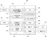
- control box configuration As shown in FIG. 4, the control box 200 includes a CPU 202 that controls the device itself, a program ROM 204 that stores various programs, content data, reference image data indicating the right palm and the back, the left palm and the back, and others. A non-volatile flash ROM 206 for storing various data and a RAM 208 as a work area are provided.
- the control box 200 is used by being attached to the user's waist or the like, for example.
- control box 200 includes a CCD camera connection I / F 210 to which the CCD camera 300 is connected.
- the CCD camera connection I / F 210 includes a CCD camera connection controller 2102 and a CCD camera VRAM (Video RAM) 2104.
- the CCD camera connection controller 2102 controls input (reception) of captured image data from the CCD camera 300 based on a command from the CPU 202.
- the CCD camera VRAM 2104 stores an image captured by the CCD camera 300.
- the control box 200 includes an HMD connection I / F 212 to which the HMD 100 is connected.
- the HMD connection I / F 212 includes an HMD connection controller 2122 and an HMD VRAM 2124.
- the HMD connection controller 2122 controls input / output (transmission / reception) of signals including various data with the HMD 100 (the image presentation device 114) based on a command from the CPU 202.
- the HMD VRAM 2124 stores content images output to the image presentation device 114.
- the control box 200 further includes a peripheral I / F 214 and a communication unit 216.
- a peripheral I / F 214 for example, a lamp 310 that illuminates an imaging position by the CCD camera 300, and the power switch 320 of the HMD 100 and the control box 200 are connected.
- the communication unit 216 receives an input of a predetermined instruction from, for example, a keyboard (not drawn in FIG. 4).
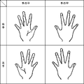
- the flash ROM 206 stores, as reference image data indicating the right palm and back and the left hand and back, the right palm image, the right hand back image, the left palm image, and the left hand back.
- Each image is an image serving as a criterion for pattern matching performed in palm determination (S110 in FIG. 6; see FIG. 8 for details) described later.
- the outer shapes (outlines) of the right palm and the back of the left hand are compared, they are substantially the same.
- the outer shapes (contours) of the back of the right hand and the palm of the left hand are substantially the same.
- these images are referred to as “reference patterns”.
- the CPU 202 acquires a content image by executing a program for reproducing (rendering) content data stored in the flash ROM 206 on the RAM 208. Then, the CPU 202 executes a program for controlling the HMD connection I / F 212 on the RAM 208 and instructs the HMD connection controller 2122 to output a content image signal including a content image to the HMD 100.
- the CPU 202 analyzes an aspect of the user's hand by executing an analysis program (for example, a program for pattern matching) on the RAM 208 using the image of the user's hand.
- the image of the user's hand is input from the CCD camera 300 via the CCD camera connection I / F 210 and stored in the CCD camera VRAM 2104 by the CCD camera connection controller 2102.
- the CPU 202 executes a program for controlling the HMD 100 on the RAM 208, and controls the operation of the HMD 100 based on the instruction received by the communication unit 216 and the operation of the HMD 100 based on the analysis result. Therefore, the CPU 202 executes various programs stored in the program ROM 204 on the RAM 208 using the content data and various data such as hand images, whereby various functional means (for example, control means and image analysis means) are configured. Is done.
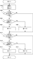
- the main processing of the first form shown in FIG. 6 is that the HMD 100 and the control box 200 are turned on, and content data playback instructions are input via, for example, a keyboard connected to the communication unit 216.
- the process is started on the condition that the CPU 202 has acquired. Specifically, the CPU 202 executes a predetermined program stored in the program ROM 204 on the RAM 208 on the condition that the reproduction instruction is acquired, and starts this processing.
- the CPU 202 reads content data from the flash ROM 206 onto the RAM 208.
- the CPU 202 executes a rendering process on the content data on the RAM 208 and generates a predetermined content image. For example, the CPU 202 generates a content image indicating the first page slide among the content data composed of a plurality of slides. Then, the CPU 202 stores the generated content image, for example, the content image indicating the slide of the first page in the HMD VRAM 2124.
- the CPU 202 instructs the HMD connection controller 2122 to output a content image signal including a content image on the HMD VRAM 2124.
- the HMD connection controller 2122 controls the HMD connection I / F 212 based on a command from the CPU 202, and transmits a content image signal to the HMD 100 (S100).
- the image presentation device 114 acquires the content image signal transmitted by the control box 200 via an input / output I / F that is not drawn in FIGS.
- the image presentation device 114 presents a content image based on the content image signal. Specifically, the image presentation device 114 optically emits the content image toward the half mirror 116. Thereby, the user wearing the HMD 100 visually recognizes and recognizes the content image.
- the user visually recognizes and recognizes a content image (slide of the first page) containing a work instruction relating to assembly work of a predetermined product as shown in FIG. Then, as shown in FIG. 7B, a predetermined product is assembled using both left and right hands.
- the CPU 202 that has started the reproduction of the content data reads the captured image from the CCD camera VRAM 2104 (S102), and determines whether or not the captured image includes a portion drawn with “skin color” indicating the color of the user's hand. (S104).
- This captured image is received by the CCD camera connection controller 2102 controlled by the CCD camera connection I / F 210 and stored in the CCD camera VRAM 2104.
- the CPU 202 determines whether or not the ratio of the values of each color is within a predetermined range.
- the CPU 202 returns the process to S102 and continues to read the captured image from the CCD camera VRAM 2104.
- the CPU 202 extracts the skin color part from the captured image (S106), and extracts the outline of the extracted part (S108).
- the CPU 202 executes pattern matching processing on the contour extracted in S108 (S110).
- the CPU 202 that has started the pattern matching process shown in FIG. 8 first clears a memory area (a predetermined area of the RAM 208) that stores the result of the determination process (S200). Subsequently, in S202, the CPU 202 reads the contour extracted in S108 (see FIG. 6) (hereinafter referred to as “extracted contour”) and the reference patterns (see FIG. 5) of the right palm and back of the right hand stored in the flash ROM 206. The pattern matching process is executed between. Then, it is determined whether or not identity is recognized between the extracted contour and each reference pattern of the palm of the right hand or the back of the left hand. As described above, since the contours of the outer shape of the right palm and the back of the left hand are substantially the same, in S202, determination based on both of these reference patterns is performed.
- the CPU 202 determines whether the extracted outline matches each reference pattern of the palm of the right hand or the back of the left hand (S204). Specifically, the CPU 202 determines in S204 based on whether or not a contour indicating a nail is recognized at the tip of the finger excluding the thumb (see the reference patterns of the right palm and the back of the left hand in FIG. 5). As a result of the determination, when the contour indicating the nail is not recognized (S204: No), the CPU 202 specifies that the extracted contour indicates the palm of the right hand (S206). On the other hand, when the outline indicating the nail is recognized (S204: Yes), the CPU 202 specifies that the extracted outline indicates the back of the left hand (S208).
- the CPU 202 executes a pattern matching process between the extracted contour and the reference patterns of the back of the right hand and the palm of the left hand (see FIG. 5). To do. Then, the CPU 202 determines whether or not the identity is recognized between the extracted contour and each reference pattern of the back of the right hand or the palm of the left hand. As described above, since the contours of the outer shape of the back of the right hand and the palm of the left hand are substantially the same, in S210, determination based on both of these reference patterns is performed.
- the CPU 202 determines whether the extracted contour matches the reference pattern of the back of the right hand or the palm of the left hand (S212). Specifically, the CPU 202 performs the determination in S212 based on whether or not a contour indicating a nail is recognized at the tip of the finger excluding the thumb (see the reference patterns of the back of the right hand and the palm of the left hand in FIG. 5). As a result of the determination, when the contour indicating the nail is not recognized (S212: No), the CPU 202 specifies that the extracted contour indicates the palm of the left hand (S214).
- the CPU 202 specifies that the extracted outline indicates the back of the right hand (S216). Note that the CPU 202 ends this process when the determination in S210 is negative (S210: No) and after executing S206, S208, S214, and S216, and the process proceeds to S112 shown in FIG.
- the CPU 202 determines whether or not the extracted contour has been identified as indicating the palm of the right hand in S110 (see S206 in FIG. 8). As a result of the determination, if it is the palm of the right hand (S112: Yes), the CPU 202 identifies “go to the next slide” as the operation to be executed, and controls this operation (S114). For example, if a content image signal including a content image (for example, see FIG. 7A) including the slide of the first page is transmitted to the HMD 100, the CPU 202 displays the content indicating the slide of the second page. Generate an image.
- the CPU 202 transmits the content image indicating the slide of the second page to the HMD 100 by the same process as in S100 described above.
- the user who has recognized the content image indicating the slide of the first page visually recognizes and recognizes the content image indicating the slide of the second page.
- the user visually recognizes and recognizes a content image having a work instruction regarding the next work performed after the work of FIG.
- the CPU 202 determines whether or not the extracted contour indicates the back of the left hand in S110 (see S208 in FIG. 8). Judgment is made (S116). As a result of the determination, if it is the back of the left hand (S116: Yes), the CPU 202 identifies the current “continue transmission of content image signal” as the operation to be executed, and controls this operation (S118). For example, if a content image signal including a content image (for example, see FIG. 7A) including the slide of the first page is transmitted to the HMD 100, the CPU 202 continues to execute the process. As a result, the content image is continuously presented to the user wearing the HMD 100. The user continues to visually recognize and recognize the same content image.
- the CPU 202 determines whether or not the extracted contour indicates the palm of the left hand in S110 (see S214 in FIG. 8). Judgment is made (S120). As a result of the determination, if it is the palm of the left hand (S120: Yes), the CPU 202 specifies “return to the previous slide” as the operation to be executed, and controls this operation (S122). For example, if a content image signal including a content image including the slide of the second page is transmitted to the HMD 100, the CPU 202 displays a content image indicating the slide of the first page (for example, see FIG. 7A). ) Is generated.
- the CPU 202 transmits a content image indicating the slide of the first page to the HMD 100 by the same processing as that of S100 described above.
- the user who has recognized the content image indicating the slide of the second page visually recognizes and recognizes the content image indicating the slide of the first page.
- the CPU 202 determines whether or not the extracted contour indicates the back of the right hand in S110 (see S216 in FIG. 8). Judgment is made (S124). As a result of the determination, if it is the back of the right hand (S124: Yes), the CPU 202 identifies “end of reproduction” as the operation to be executed, and controls this operation (S126). For example, if a content image signal including a content image including the slide of the second page is transmitted to the HMD 100, the CPU 202 ends the transmission process. Thereby, presentation of the content image in HMD100 is complete
- the extracted contour does not indicate an image of the hand, and the shape of the hand (extracted contour) does not correspond to any of the reference patterns in FIG. Is not specified (S210: No in FIG. 8), the CPU 202 denies the determination of S124 (S124: No), and returns the process to S102. Thereby, the right hand and left hand during operation can be distinguished from the right hand and left hand during operation, and erroneous operation can be prevented.
- the CPU 202 that has started this process first executes the process of S300, and then continuously executes the processes of S302 to S308.
- each process of S300 to S308 corresponds to S100 to S108 of the main process of the first form shown in FIG.
- the CPU 202 shifts the process to S310, and executes a pattern matching process based on the extracted contour extracted in S308.
- the CPU 202 that has started the pattern matching process shown in FIG. 10 first clears the memory area (predetermined area in the RAM 208) that stores the result of this determination process. Specifically, the right hand flag and the left hand flag are initially set to “0”. (S400). Subsequently, the CPU 202 executes S402.
- the determination executed in S402 is the same processing as S202 of the pattern matching processing executed in the first mode shown in FIG. S404 executed when the determination in S402 is affirmative (S402: Yes) is the same processing as S204 shown in FIG.
- the CPU 202 shifts the process to S410.
- the determination executed in S410 is the same process as S210 of the pattern matching process executed in the first mode shown in FIG. If the determination in S410 is affirmative (S410: Yes), S412 is the same process as S212 shown in FIG.
- S412 when the extracted contour indicates the palm of the left hand (S412: No), the CPU 202 sets the left hand flag to “1” (S414), and when the extracted contour indicates the back of the right hand (S412: Yes), The right hand flag is set to “2” (S416).
- the pattern matching process of the first form shown in FIG. 8 first, the pattern matching process is executed between the extracted contour and the back of the right hand or the back of the left hand (see S202). If they do not match (S202: No), Pattern matching is executed with the palm of the left hand or the back of the right hand (see S210). That is, only the palm or back of one hand is targeted.
- pattern matching processing is executed between the extracted contour and the back of the right hand or the back of the left hand (see S402), and then pattern matching is performed between the back of the left hand or the back of the right hand. The process is executed (see S410). That is, the combination of both hands is targeted. As a result, more versatile processing can be handled.
- the CPU 202 determines whether or not the right hand flag “2” is specified and the left hand flag “2” is specified (see S ⁇ b> 408 and S ⁇ b> 416 in FIG. 10) in the pattern matching process in S ⁇ b> 310. to decide. In other words, in step S312, the CPU 202 determines whether or not the extracted contours of both the left and right hands extracted in step S308 are specified to indicate the back of the hand. As a result of the determination, if the right hand flag is “2” and the left hand flag is “2” (S312: Yes / see S408 and S416 in FIG. 10), the CPU 202 returns the process to S302.
- the CPU 202 executes the same processing as that of S118 of the first form shown in FIG. Taking the assembly work described above as an example, when the back of both hands is imaged by the CCD camera 300, it is estimated that the user wearing the HMD 100 continues to perform the assembly work. Therefore, in the configuration of the present embodiment, control is performed so that the operation being executed is continuously executed.
- the CPU 202 determines whether or not the right hand flag “1” is specified in S310. Is determined (S314). As a result of the determination, when the right hand flag is not “1” (S314: No), specifically, when the right hand flag is “0” (see S400 in FIG. 10), the CPU 202 continues to set the left hand flag “1”. Is determined (S316). As a result of the determination, if the left-hand flag is not “1” (S316: No), specifically, if the left-hand flag is “0” (see S400 in FIG. 10), the CPU 202 returns the process to S302.
- the extracted contour extracted in S308 does not correspond to either the right hand or the left hand.
- the shape of the hand (extracted outline) does not correspond to any of the reference patterns in FIG. Thereby, the right hand and left hand during operation can be distinguished from the right hand and left hand during operation, and erroneous operation can be prevented.
- the CPU 202 specifies “return to the previous slide” as the operation to be executed ( S318). That is, in the case of the right hand flag “0” and the left hand flag “1”, for example, when the extracted contour extracted in S308 is only the left hand and the left hand contour indicates the palm of the hand.
- the CPU 202 specifies “return to the previous slide” as an operation to be executed.
- S318 corresponds to S122 of the first form shown in FIG. 6, and for example, the processing described above in relation to S122 is executed in S318. After executing S318, the CPU 202 returns the process to S302.
- the CPU 202 subsequently determines whether or not the left hand flag “1” is specified (S320). ). As a result of the determination, if the left-hand flag is not “1” (S320: No), specifically, if the left-hand flag is “0” (see S400 in FIG. 10), the CPU 202 “ “Proceed to next slide” is specified (S322). That is, in the case of the right hand flag “1” and the left hand flag “0”, for example, when the extracted contour extracted in S308 is only the right hand and the contour of the right hand indicates a palm. The CPU 202 specifies “go to the next slide” as an operation to be executed. Note that S322 corresponds to S114 of the first form illustrated in FIG. 6. For example, the processing described above in relation to S114 is executed in S322.
- the CPU 202 specifies “reproduction end” as the operation to be executed (S324).
- the CPU 202 specifies “end of reproduction” as an operation to be executed (S324).
- S324 corresponds to S126 of the first form shown in FIG. 6, and for example, the processing described above in relation to S126 is executed. Note that after executing S324, the CPU 202 ends this process.
- the state of the hand of the user wearing the HMD 100 is analyzed (see FIG. 6, S110 in FIG. 6 (refer to FIG. 8 in detail, and FIG. 10 in detail), and a configuration for controlling the operation realized by the HMD 100 and the control box 200 based on the analysis result (S114 in FIG. 6).
- S118, S122, S126, S312 of FIG. 9: No, S318, S322, and S324 are employed.
- the operation realized by the HMD 100 and the control box 200 can be realized in a hands-free manner without directly operating the apparatus main body.
- the user can turn his / her right hand toward the CCD camera 300 while viewing a content image including a work instruction related to the first process for assembling a predetermined product.
- the work instructions relating to the second step can be visually recognized and recognized (see S112 in FIG. 6: Yes, S114).
- the reproduction of the content can be terminated by directing both the left and right palms to the CCD camera 300 (S314, S320: Yes, S324 in FIG. 9).
- the palm since the palm is not shown or few during the work, it is possible to distinguish the movement of the hand during the work from the shape of the hand during the operation, thereby preventing an erroneous operation.
Landscapes
- Engineering & Computer Science (AREA)
- General Engineering & Computer Science (AREA)
- Physics & Mathematics (AREA)
- Theoretical Computer Science (AREA)
- General Physics & Mathematics (AREA)
- Human Computer Interaction (AREA)
- Optics & Photonics (AREA)
- Image Analysis (AREA)
- Image Processing (AREA)
- Control Of Indicators Other Than Cathode Ray Tubes (AREA)
- User Interface Of Digital Computer (AREA)
Abstract
利用者の眼に、コンテンツデータにより示されるコンテンツ画像を視認可能に提示し、利用者にコンテンツ画像を認識させるヘッドマウントディスプレイであって、ヘッドマウントディスプレイの動作を制御する制御手段と、利用者の手を撮像する撮像手段と、撮像手段が撮像した手の画像を解析する画像解析手段と、を備える。制御手段は、画像解析手段が、手の平及び手の甲と、右手及び左手と、の少なくともいずれか一対を対象として、撮像手段により撮像された手の画像を解析した結果にしたがって(S112、S116,S120,S124)、ヘッドマウントディスプレイの所定の動作を制御する(S114,S118,S122,S126)。
Description
本開示は、利用者の眼にコンテンツデータにより示されるコンテンツ画像を視認可能に提示し、この利用者にコンテンツ画像を認識させるヘッドマウントディスプレイに関するものである。
利用者の眼にコンテンツデータにより示されるコンテンツ画像を視認可能に提示し、この利用者にコンテンツ画像を認識させるヘッドマウントディスプレイに関する技術が提案されている。例えば、外界像を観察(視認)可能なシースルー型のヘッドマウントディスプレイにおいて、利用者が、ヘッドマウントディスプレイに備えられた赤外線センサ付近に自身の手を近づけた場合、ヘッドマウントディスプレイに内蔵された液晶シャッタへの電流の通電、遮断を制御するスイッチ制御回路が駆動し、液晶シャッタをオフ状態に設定し、外界像を観察できるようにする技術が提案されている。これによって、利用者は、装置に手を触れることなく、映像鑑賞状態(コンテンツ画像を視認している状態)と外界像観察状態とを、容易に切り替えることができるとされている(例えば、特許文献1)。なお、このヘッドマウントディスプレイによれば、赤外線センサの検知距離は10cm以内とすることで、誤動作を回避することができるとされている。
ところで、ヘッドマウントディスプレイが利用される場面として、例えば、所定の製品の生産現場が想定される。すなわち、ヘッドマウントディスプレイを用いて製品の組立てに関する作業指示を、これを装着する利用者に提示し、この利用者が、手作業で製品を組み立てるような場面が想定される。したがって、このような場面において、ヘッドマウントディスプレイの動作を指示するための操作を適切かつ効率的に行える構成は有用である。
本開示は、ヘッドマウントディスプレイの動作を指示するための操作に関し、操作性に優れた新たなヘッドマウントディスプレイを提供することを目的とする。
本開示のヘッドマウントディスプレイは、利用者の手を撮像し、撮像した手の画像を解析し、解析の結果得られた利用者の手の態様が、一の態様であると解析された場合、一の動作の実行を制御し、他の態様であると解析された場合、他の動作を制御することとしたものである。
本開示の一側面によれば、利用者の眼に、コンテンツデータにより示されるコンテンツ画像を視認可能に提示し、前記利用者に前記コンテンツ画像を認識させるヘッドマウントディスプレイであって、前記ヘッドマウントディスプレイの動作を制御する制御手段と、前記利用者の手を撮像する撮像手段と、前記撮像手段が撮像した手の画像を解析する画像解析手段と、を備え、前記制御手段は、前記画像解析手段が、手の平及び手の甲と、右手及び左手と、の少なくともいずれか一対を対象として、前記撮像手段により撮像された手の画像を解析した結果にしたがって、前記ヘッドマウントディスプレイの所定の動作を制御することを特徴とするヘッドマウントディスプレイを得ることができる。
このようなヘッドマウントディスプレイによれば、ヘッドマウントディスプレイの動作を指示するための操作に関し、優れた操作性を実現することができる。
本開示の他の側面によれば、前記画像解析手段は、手の平及び手の甲を対象として、前記撮像手段により撮像された手の画像を解析可能で、前記制御手段は、前記画像解析手段が、前記撮像手段により撮像された手の画像が手の平を示すものであると解析した場合、前記ヘッドマウントディスプレイの第1動作を制御し、前記撮像手段により撮像された手の画像が手の甲を示すものであると解析した場合、前記ヘッドマウントディスプレイの第2動作を制御することを特徴とするヘッドマウントディスプレイを得ることができる。
このようなヘッドマウントディスプレイでは、ヘッドマウントディスプレイの利用者の手の平と手の甲とを識別することによって、ヘッドマウントディスプレイの各動作を制御することが可能で、ヘッドマウントディスプレイの操作性を向上させることができる。
本開示のさらに他の側面によれば、前記画像解析手段は、右手及び左手を対象として、前記撮像手段により撮像された手の画像を解析可能で、前記制御手段は、前記画像解析手段が、前記撮像手段により撮像された手の画像が右手を示すものであると解析した場合、前記ヘッドマウントディスプレイの第1動作を制御し、前記撮像手段により撮像された手の画像が左手を示すものであると解析した場合、前記ヘッドマウントディスプレイの第2動作を制御することを特徴とするヘッドマウントディスプレイを得ることができる。
このようなヘッドマウントディスプレイでは、ヘッドマウントディスプレイの利用者の右手と左手とを識別することによって、ヘッドマウントディスプレイの各動作を制御することが可能で、ヘッドマウントディスプレイの操作性を向上させることができる。
本開示のさらに他の側面によれば、前記画像解析手段は、手の平及び手の甲と、右手及び左手と、を対象として、前記撮像手段により撮像された手の画像を解析可能で、前記制御手段は、前記画像解析手段が、前記撮像手段により撮像された手の画像が右手の平を示すものであると解析した場合、前記ヘッドマウントディスプレイの第1動作を制御し、前記撮像手段により撮像された手の画像が左手の甲を示すものであると解析した場合、前記ヘッドマウントディスプレイの第2動作を制御し、前記撮像手段により撮像された手の画像が左手の平を示すものであると解析した場合、前記ヘッドマウントディスプレイの第3動作を制御し、前記撮像手段により撮像された手の画像が右手の甲を示すものであると解析した場合、前記ヘッドマウントディスプレイの第4動作を制御することを特徴とするヘッドマウントディスプレイを得ることができる。
このようなヘッドマウントディスプレイでは、ヘッドマウントディスプレイの利用者の右手の平と右手の甲と左手の平と左手の甲とを識別することによって、ヘッドマウントディスプレイの各動作を制御することが可能で、ヘッドマウントディスプレイの操作性を向上させることができる。
本開示のさらに他の側面によれば、前記撮像手段は、前記利用者の右手及び左手を撮像可能で、前記画像解析手段は、前記撮像手段が撮像した右手及び左手の画像を解析可能であるとともに、手の平及び手の甲を対象として、前記撮像手段により撮像された右手及び左手の画像を解析可能で、前記制御手段は、前記ヘッドマウントディスプレイの第5動作を制御している場合に、前記画像解析手段が、前記撮像手段により撮像された手の画像が右手の甲と左手の甲とを示すものであると解析した場合、前記ヘッドマウントディスプレイの第5動作の制御を継続し、前記撮像手段により撮像された手の画像が、右手の平と左手の平とを示すものであると解析した場合と、右手の平と左手の甲とを示すものであると解析した場合と、右手の甲と左手の平とを示すものであると解析した場合と、に前記ヘッドマウントディスプレイの第5動作とは異なる動作を制御することを特徴とするヘッドマウントディスプレイを得ることができる。
このようなヘッドマウントディスプレイでは、ヘッドマウントディスプレイの利用者の右手の平又は右手の甲と、左手の平又は左手の甲との組合せを識別することによって、ヘッドマウントディスプレイの各動作を制御することが可能で、ヘッドマウントディスプレイの操作性を向上させることができる。特に、右手の甲と左手の甲との組合せである場合、実行中の動作が継続される一方、右手と左手との少なくともいずれかの手の平が撮像手段側に向けられた場合、実行中の動作とは異なる動作が制御される。
なお、「ヘッドマウントディスプレイの動作」は、例えば、コンテンツデータに対するものの他、ヘッドマウントディスプレイへの電源の供給若しくは遮断、その他ヘッドマウントディスプレイにおいて実現される各種動作を含む。また、ヘッドマウントディスプレイは、必ずしも1つの装置である必要はなく、例えば、2つの装置による構成であってもよい。例えば、制御手段と画像解析手段とを別の装置として構成し、ヘッドマウントディスプレイと所定の信号ケーブルで接続した構成とすることもできる。
本開示を反映した実施形態について、図面を用いて以下に詳細に説明する。なお、本開示は、以下に記載の構成に限定されるものではなく、同一の技術的思想において種々の構成を採用することができる。例えば、以下の説明では、ヘッドマウントディスプレイ本体と、ヘッドマウントディスプレイ本体にコンテンツ画像を提供する制御ボックスと、を接続して構成されたヘッドマウントディスプレイを例に説明するが、これら各装置を一体の装置として構成することもできる。なお、以下の説明において、ヘッドマウントディスプレイ本体を、単にヘッドマウントディスプレイ(Head Mounted Display/以下、「HMD」という。)という。
(ヘッドマウントディスプレイの概要)
図1に示されるように、HMD100は、テンプル104A,104Bと、ヨロイ106A,106Bと、フロントフレーム108とを備える。テンプル104A,104Bの一端には、利用者の耳に当たるモダン102A,102Bが取り付けられる。テンプル104A,104Bの他端には、兆番112A,112Bが設けられる。テンプル104A,104Bとヨロイ106A,106Bとは、この兆番112A,112Bを介して連結される。フロントフレーム108は、ヨロイ106A,106Bを連結する。フロントフレーム108の中央部には、利用者の鼻に当接する鼻パッド110が取り付けられる。テンプル104A,104B、ヨロイ106A,106B、フロントフレーム108及び鼻パッド110によって、HMD100の骨格部が形成されている。ヨロイ106A,106Bに形成された兆番112A,112Bでテンプル104A,104Bを折りたたむことができる。HMD100の骨格部の構成は、例えば、通常の眼鏡と同様である。図2に示されるように、HMD100は、利用者に装着された状態において、モダン102A,102Bと、鼻パッド110と、により利用者の顔に支持される。なお、図1(b)において、モダン102A,102B及びテンプル104A,104Bの描画を省略している。
図1に示されるように、HMD100は、テンプル104A,104Bと、ヨロイ106A,106Bと、フロントフレーム108とを備える。テンプル104A,104Bの一端には、利用者の耳に当たるモダン102A,102Bが取り付けられる。テンプル104A,104Bの他端には、兆番112A,112Bが設けられる。テンプル104A,104Bとヨロイ106A,106Bとは、この兆番112A,112Bを介して連結される。フロントフレーム108は、ヨロイ106A,106Bを連結する。フロントフレーム108の中央部には、利用者の鼻に当接する鼻パッド110が取り付けられる。テンプル104A,104B、ヨロイ106A,106B、フロントフレーム108及び鼻パッド110によって、HMD100の骨格部が形成されている。ヨロイ106A,106Bに形成された兆番112A,112Bでテンプル104A,104Bを折りたたむことができる。HMD100の骨格部の構成は、例えば、通常の眼鏡と同様である。図2に示されるように、HMD100は、利用者に装着された状態において、モダン102A,102Bと、鼻パッド110と、により利用者の顔に支持される。なお、図1(b)において、モダン102A,102B及びテンプル104A,104Bの描画を省略している。
HMD100の骨格部には、画像提示装置114が、ヨロイ106A付近に配設された取付部122を介して取り付けられている。画像提示装置114は、ヨロイ106A付近に取付部122を介して取り付けられた状態において、HMD100を装着した利用者の左眼118と略同一の高さとなる位置に配設される。図2に示されるように、画像提示装置114は、制御ボックス200と、所定の信号ケーブル250を介して接続されている。詳細は後述するが、制御ボックス200は、図4に示すフラッシュROM206などの所定の記憶領域に記憶されたコンテンツデータに対しレンダリング処理を実行する。制御ボックス200は、図4に示す自装置が備えるHMD接続インターフェース(以下、「I/F」という。)212を制御し、再生処理(レンダリング処理)によって得られたコンテンツ画像を含むコンテンツ画像信号を、信号ケーブル250を介して画像提示装置114に出力(送信)する。画像提示装置114は、制御ボックス200が出力するコンテンツ画像信号を、図1及び2には描画していない入出力I/Fを介して取得する。そして、コンテンツ画像信号に基づくコンテンツ画像を、ハーフミラー116に向けて光学的に出射する。
画像提示装置114から出射されたコンテンツ画像(光線)は、ハーフミラー116で、反射し、利用者の左眼118に入射、換言すれば、視認可能に提示(投影)される。これにより、利用者はコンテンツ画像を認識する。ここで、図1(a)において符号120aは、画像提示装置114から出射されたコンテンツ画像に関する光線を示し、符号120bは、ハーフミラー116で反射し、利用者の左眼118に入射する光線を示す。なお、画像提示装置114は、取得したコンテンツ画像信号に応じた光線120a,120bを2次元方向に走査し、その走査された光線120a,120bを利用者の左眼118に導き網膜上にコンテンツ画像を形成する網膜走査型のディスプレイを用いて構成することができる他、液晶ディスプレイ、有機EL(Organic Electroluminescence)ディスプレイその他の装置を用いた構成とすることもできる。
画像提示装置114の上面には、図1及び2に示すように利用者の手を撮像可能なCCDカメラ300が取り付けられている。なお、CCDカメラ300は、例えば図3に示されるような外観を有する。
(制御ボックスの構成)
図4に示されるように、制御ボックス200は、自装置の制御を司るCPU202と、各種プログラムを記憶するプログラムROM204と、コンテンツデータ、右手の平及び甲と左手の平及び甲とを示す基準画像データその他各種データを記憶する不揮発性のフラッシュROM206と、作業領域としてのRAM208とを備える。なお、制御ボックス200は、例えば、利用者の腰等に取り付け、利用される。
図4に示されるように、制御ボックス200は、自装置の制御を司るCPU202と、各種プログラムを記憶するプログラムROM204と、コンテンツデータ、右手の平及び甲と左手の平及び甲とを示す基準画像データその他各種データを記憶する不揮発性のフラッシュROM206と、作業領域としてのRAM208とを備える。なお、制御ボックス200は、例えば、利用者の腰等に取り付け、利用される。
また、制御ボックス200は、CCDカメラ300が接続されるCCDカメラ接続I/F210を備える。CCDカメラ接続I/F210は、CCDカメラ接続コントローラ2102と、CCDカメラ用VRAM(Video RAM)2104とを搭載する。CCDカメラ接続コントローラ2102は、CCDカメラ300からの撮像画像データの入力(受信)を、CPU202からの指令に基づき制御する。CCDカメラ用VRAM2104は、CCDカメラ300によって撮像された画像を記憶する。
また、制御ボックス200は、HMD100が接続されるHMD接続I/F212を備える。HMD接続I/F212は、HMD接続コントローラ2122と、HMD用VRAM2124とを搭載する。HMD接続コントローラ2122は、CPU202からの指令に基づきHMD100(画像提示装置114)との間の各種データを含む信号の入出力(送受信)を制御する。HMD用VRAM2124は、画像提示装置114に出力されるコンテンツ画像を記憶する。
さらに、制御ボックス200は、周辺I/F214と、通信部216とを備える。周辺I/F214には、例えば、CCDカメラ300による撮像位置を照らすランプ310と、HMD100及び制御ボックス200の電源スイッチ320とが接続される。通信部216は、例えば、キーボード(図4において描画せず)から所定の指示の入力を受け付ける。
図5に示されるように、フラッシュROM206には、右手の平及び甲と左手の平及び甲とを示す基準画像データとして、右手の平の画像と、右手の甲の画像と、左手の平の画像と、左手の甲の画像と、が記憶されている。各画像は、後述する手の平判定(図6のS110、詳細には図8参照)において実施されるパターンマッチング処理の判定基準となる画像である。ここで、右手の平及び左手の甲について、各々の外形(輪郭)を比較すると、両者は各々略同一である。同じく右手の甲及び左手の平についても、各々の外形(輪郭)は略同一である。なお、以下の説明において、これら画像を「基準パターン」という。
CPU202は、フラッシュROM206に記憶されているコンテンツデータを再生(レンダリング)するためのプログラムを、RAM208上で実行することで、コンテンツ画像を取得する。そして、CPU202は、HMD接続I/F212を制御するためのプログラムをRAM208上で実行し、コンテンツ画像を含むコンテンツ画像信号のHMD100への出力を、HMD接続コントローラ2122に指令する。
また、CPU202は、利用者の手の画像を用いて、解析用プログラム(例えば、パターンマッチングのためのプログラム)をRAM208上で実行することで、利用者の手の態様について解析する。利用者の手の画像は、CCDカメラ300からCCDカメラ接続I/F210を介して入力され、CCDカメラ接続コントローラ2102によってCCDカメラ用VRAM2104に記憶されたものである。さらに、CPU202は、HMD100を制御するためのプログラムをRAM208上で実行し、通信部216が受け付けた指示に基づいたHMD100の動作と、解析結果に基づいたHMD100の動作と、を制御する。したがって、CPU202が、コンテンツデータと手の画像等の各種データを用い、プログラムROM204に記憶された各種プログラムをRAM208上で実行することにより、各種機能手段(例えば、制御手段及び画像解析手段)が構成される。
(制御ボックスによって実行される処理の第1形態)
図6に示される、第1形態のメイン処理は、HMD100及び制御ボックス200の電源がONされ、コンテンツデータの再生指示が、例えば、通信部216に接続されたキーボードを介して入力され、これをCPU202が取得したことを条件として開始される。詳細には、CPU202は、再生指示の取得を条件として、プログラムROM204に記憶された所定のプログラムをRAM208上で実行し、この処理を開始する。
図6に示される、第1形態のメイン処理は、HMD100及び制御ボックス200の電源がONされ、コンテンツデータの再生指示が、例えば、通信部216に接続されたキーボードを介して入力され、これをCPU202が取得したことを条件として開始される。詳細には、CPU202は、再生指示の取得を条件として、プログラムROM204に記憶された所定のプログラムをRAM208上で実行し、この処理を開始する。
先ず、CPU202は、フラッシュROM206から、コンテンツデータをRAM208上に読み出す。CPU202は、RAM208上のコンテンツデータに対してレンダリング処理を実行し、所定のコンテンツ画像を生成する。例えば、CPU202は、複数のスライドから構成されるコンテンツデータの内、第1頁目のスライドを示すコンテンツ画像を生成する。そして、CPU202は、生成したコンテンツ画像、例えば、第1頁目のスライドを示すコンテンツ画像をHMD用VRAM2124に記憶する。CPU202は、HMD接続コントローラ2122に対して、HMD用VRAM2124上のコンテンツ画像を含むコンテンツ画像信号の出力を指令する。HMD接続コントローラ2122は、CPU202の指令に基づきHMD接続I/F212を制御し、コンテンツ画像信号をHMD100に送信する(S100)。HMD100において画像提示装置114は、制御ボックス200が送信したコンテンツ画像信号を、図1及び2には描画していない入出力I/Fを介して取得する。画像提示装置114は、コンテンツ画像信号に基づくコンテンツ画像を提示、詳細には、コンテンツ画像をハーフミラー116に向けて光学的に出射する。これにより、HMD100を装着した利用者は、コンテンツ画像を視認し、認識する。具体的に、利用者は、図7(a)に示すような所定の製品の組立作業に関する作業指図を内容とするコンテンツ画像(第1頁目のスライド)を視認し、認識する。そして、図7(b)に示すように左右両手を用いて所定の製品の組み立てを実施する。
コンテンツデータの再生を開始したCPU202は、撮像画像をCCDカメラ用VRAM2104から読み出し(S102)、撮像画像に利用者の手の色を示す「肌色」で描画された部分があるか否かを判断する(S104)。この撮像画像は、CCDカメラ接続コントローラ2102によって、CCDカメラ接続I/F210が制御され、受信され、CCDカメラ用VRAM2104に記憶されたものである。例えば、撮像画像が、RGB(赤、緑及び青の三原色)で表わされる画像である場合、CPU202は、各色の値の比が所定の範囲にあるか否かで判断する。判断の結果、撮像画像に肌色部分が存在しない場合(S104:No)、CPU202は、処理をS102に戻し、継続して、CCDカメラ用VRAM2104から撮像画像を読み出す。
これに対し、撮像画像に肌色部分が存在する場合(S104:Yes)、CPU202は、撮像画像から肌色部分を抽出し(S106)、抽出した部分の輪郭を抽出する(S108)。そして、CPU202は、S108において抽出した輪郭に対しパターンマッチング処理を実行する(S110)。
図8に示されるパターンマッチング処理を開始したCPU202は、先ず、この判定処理の結果を記憶するメモリ領域(RAM208の所定領域)をクリアする(S200)。続けて、S202でCPU202は、S108(図6参照)で抽出した輪郭(以下、「抽出輪郭」という。)とフラッシュROM206に記憶された右手の平及び左手の甲の各基準パターン(図5参照)との間でパターンマッチング処理を実行する。そして、抽出輪郭と右手の平又は左手の甲の各基準パターンとの間に同一性が認められるか否かを判断する。なお、上述したとおり、右手の平と左手の甲の外形の輪郭は略同一であるため、S202では、これら両方の基準パターンに基づいた判断が行われる。
S202の判断の結果、同一性が認められる場合(S202:Yes)、CPU202は、抽出輪郭が右手の平又は左手の甲の各基準パターンのいずれに一致するかを判断する(S204)。具体的には、CPU202は、親指を除く指の先端部分に爪を示す輪郭が認められるか否かに基づき、S204の判断を行う(図5の右手の平及び左手の甲の各基準パターン参照)。判断の結果、爪を示す輪郭が認められない場合(S204:No)、CPU202は、抽出輪郭が右手の平を示すものであると特定する(S206)。これに対し、爪を示す輪郭が認められた場合(S204:Yes)、CPU202は、抽出輪郭が左手の甲を示すものであると特定する(S208)。
S202の判断の結果、同一性が認められない場合(S202:No)、S210でCPU202は、抽出輪郭と右手の甲及び左手の平の各基準パターン(図5参照)との間でパターンマッチング処理を実行する。そして、CPU202は、抽出輪郭と右手の甲又は左手の平の各基準パターンとの間に同一性が認められるか否かを判断する。なお、上述したとおり、右手の甲と左手の平の外形の輪郭は略同一であるため、S210では、これら両方の基準パターンに基づいた判断が行われる。
S210の判断の結果、同一性が認められる場合(S210:Yes)、CPU202は、抽出輪郭が右手の甲又は左手の平の各基準パターンのいずれに一致するかを判断する(S212)。具体的には、CPU202は、親指を除く指の先端部分に爪を示す輪郭が認められるか否かに基づき、S212の判断を行う(図5の右手の甲及び左手の平の各基準パターン参照)。判断の結果、爪を示す輪郭が認められない場合(S212:No)、CPU202は、抽出輪郭が左手の平を示すものであると特定する(S214)。これに対し、爪を示す輪郭が認められた場合(S212:Yes)、CPU202は、抽出輪郭が右手の甲を示すものであると特定する(S216)。なお、CPU202は、S210の判断が否定された場合(S210:No)、及びS206、S208,S214,S216を実行した後、この処理を終了し、処理を図6に示すS112に移行する。
説明を図6に戻し、S112でCPU202は、S110で抽出輪郭が右手の平を示すものであると特定(図8のS206参照)されたか否かを判断する。判断の結果、右手の平である場合(S112:Yes)、CPU202は、実行すべき動作として「次のスライドへ進む」を特定し、この動作を制御する(S114)。例えば、第1頁目のスライドを内容とするコンテンツ画像(例えば、図7(a)参照)を含むコンテンツ画像信号がHMD100に送信されていれば、CPU202は、第2頁目のスライドを示すコンテンツ画像を生成する。そして、CPU202は、第2頁目のスライドを示すコンテンツ画像を、上述したS100と同様の処理によってHMD100に送信する。これにより、第1頁目のスライドを示すコンテンツ画像を認識していた利用者は、第2頁目のスライドを示すコンテンツ画像を視認し、認識する。例えば、利用者は、図7(b)の作業後に行う、次の作業に関する作業指図を内容とするコンテンツ画像を視認し、認識する。
S110で特定された抽出輪郭が右手の平を示すものでない場合(S112:No)、CPU202は、S110で抽出輪郭が左手の甲を示すものであると特定(図8のS208参照)されたか否かを判断する(S116)。判断の結果、左手の甲である場合(S116:Yes)、CPU202は、実行すべき動作として現在の「コンテンツ画像信号の送信を継続」を特定し、この動作を制御する(S118)。例えば、第1頁目のスライドを内容とするコンテンツ画像(例えば、図7(a)参照)を含むコンテンツ画像信号がHMD100に送信されていれば、CPU202は、その処理を継続して実行する。これによって、HMD100を装着した利用者に、このコンテンツ画像が継続して提示される。利用者は継続して同一のコンテンツ画像を視認し、認識する。
S110で特定された抽出輪郭が左手の甲を示すものでない場合(S116:No)、CPU202は、S110で抽出輪郭が左手の平を示すものであると特定(図8のS214参照)されたか否かを判断する(S120)。判断の結果、左手の平である場合(S120:Yes)、CPU202は、実行すべき動作として「前のスライドへ戻る」を特定し、この動作を制御する(S122)。例えば、第2頁目のスライドを内容とするコンテンツ画像を含むコンテンツ画像信号がHMD100に送信されていれば、CPU202は、第1頁目のスライドを示すコンテンツ画像(例えば、図7(a)参照)を生成する。そして、CPU202は、第1頁目のスライドを示すコンテンツ画像を、上述したS100と同様の処理によってHMD100に送信する。これにより、第2頁目のスライドを示すコンテンツ画像を認識していた利用者は、第1頁目のスライドを示すコンテンツ画像を視認し、認識する。
S110で特定された抽出輪郭が左手の平を示すものでない場合(S120:No)、CPU202は、S110で抽出輪郭が右手の甲を示すものであると特定(図8のS216参照)されたか否かを判断する(S124)。判断の結果、右手の甲である場合(S124:Yes)、CPU202は、実行すべき動作として「再生終了」を特定し、この動作を制御する(S126)。例えば、第2頁目のスライドを内容とするコンテンツ画像を含むコンテンツ画像信号がHMD100に送信されていれば、CPU202は、この送信処理を終了する。これにより、HMD100におけるコンテンツ画像の提示が終了する。なお、抽出輪郭が手の画像を示すものではなく、また、例えば、物を握って作業中等、手の形(抽出輪郭)が、図5の基準パターンのいずれにも該当せず、S110で何らの特定もなされていない場合(図8のS210:No)、CPU202は、S124の判断を否定し(S124:No)、処理をS102に戻す。これにより、作業時の右手、左手と操作時の右手、左手とを区別可能で、誤操作を防止できる。
ここで、上述した抽出輪郭の特定、具体的には、「右手の平」等の特定に関し(図6のS112,S116,S120,S124及び図8のS206,S208,S214,S216参照)、後述するようなフラグを用いた構成を採用することもできる。
(制御ボックスによって実行される処理の第2形態)
図9に示される第2形態のメイン処理は、上述した第1形態のメイン処理と同一の条件の下、開始される。なお、以下の説明において、上述した第1形態と同一の処理については、第1形態の対応するステップ番号のみ記載することとし、その詳細な説明は省略する。
図9に示される第2形態のメイン処理は、上述した第1形態のメイン処理と同一の条件の下、開始される。なお、以下の説明において、上述した第1形態と同一の処理については、第1形態の対応するステップ番号のみ記載することとし、その詳細な説明は省略する。
この処理を開始したCPU202は、先ず、S300の処理を実行し、その後、継続してS302~S308の処理を実行する。ここで、S300~S308の各処理は、図6に示す第1形態のメイン処理のS100~S108に対応する。S308を実行した後、CPU202は処理をS310に移行し、S308で抽出した抽出輪郭に基づきパターンマッチング処理を実行する。
図10に示されるパターンマッチング処理を開始したCPU202は、先ず、この判定処理の結果を記憶するメモリ領域(RAM208の所定領域)をクリア、詳細には、右手フラグ及び左手フラグを「0」に初期化する(S400)。続けて、CPU202は、S402を実行する。ここで、S402で実行される判断は、図8に示す第1形態において実行されるパターンマッチング処理のS202と同一の処理である。S402の判断が肯定された場合(S402:Yes)に実行されるS404は、図8に示すS204と同一の処理である。S404の判断の結果、抽出輪郭が右手の平を示す場合(S404:No)、CPU202は、右手フラグを「1」にセットし(S406)、抽出輪郭が左手の甲を示す場合(S404:Yes)、左手フラグを「2」にセットする(S408)。なお、フラグ「1」は手の平を示すものであり、フラグ「2」は手の甲を示すものである。その後、CPU202は処理をS410に移行する。
S402の判断が否定された場合(S402:No)、CPU202は処理をS410に移行する。ここで、S410で実行される判断は、図8に示す第1形態において実行されるパターンマッチング処理のS210と同一の処理である。S410の判断が肯定された場合(S410:Yes)に実行されるS412は、図8に示すS212と同一の処理である。S412の判断の結果、抽出輪郭が左手の平を示す場合(S412:No)、CPU202は、左手フラグを「1」にセットし(S414)、抽出輪郭が右手の甲を示す場合(S412:Yes)、右手フラグを「2」にセットする(S416)。そして、CPU202は、この第2形態におけるパターンマッチング処理を終了し、処理を図9に示すS312に移行する。なお、S410の判断が否定された場合(S410:No)も、CPU202は処理を図9に示すS312に移行する。
図8に示す第1形態のパターンマッチング処理では、先ず、抽出輪郭と右手の平又は左手の甲との間でパターンマッチング処理を実行し(S202参照)、一致しない場合(S202:No)、抽出輪郭と左手の平又は右手の甲との間でパターンマッチングを実行する(S210参照)。すなわち、片方の手の平又は甲のみを対象とする。これに対し、図10に示す第2形態では、抽出輪郭と右手の平又は左手の甲との間でパターンマッチング処理を実行し(S402参照)、次に、左手の平又は右手の甲との間でパターンマッチング処理を実行する(S410参照)。すなわち、両手の組合せを対象とする。そのため、より多用な処理に対応できる。
説明を図9に戻し、S312でCPU202は、S310のパターンマッチング処理で右手フラグ「2」が特定されるとともに、左手フラグ「2」が特定(図10のS408,S416参照)されたか否かを判断する。換言すれば、S312でCPU202は、S308で抽出された左右両手の抽出輪郭が共に手の甲を示すものであると特定されたか否かを判断する。判断の結果、右手フラグ「2」及び左手フラグ「2」である場合(S312:Yes/図10のS408,S416参照)、CPU202は処理をS302に戻す。すなわち、CPU202は、図6に示す第1形態のS118と同様の処理を実行する。上述した組立作業を例とすれば、両手の甲がCCDカメラ300によって撮像されるような場合、HMD100を装着している利用者は、組立作業を継続して実施していると推定される。そのため、本実施形態の構成では、実行中の動作が継続して実行されるよう制御することとしている。
右手フラグ及び左手フラグの少なくともいずれか一方のフラグが「2」ではなく、S312の判断が否定される場合(S312:No)、CPU202は、S310で右手フラグ「1」が特定されているか否かを判断する(S314)。判断の結果、右手フラグが「1」でない場合(S314:No)、具体的には、右手フラグが「0」である場合(図10のS400参照)、続けて、CPU202は、左手フラグ「1」が特定されているか否かを判断する(S316)。判断の結果、左手フラグが「1」ではない場合(S316:No)、具体的には、左手フラグが「0」である場合(図10のS400参照)、CPU202は処理をS302に戻す。なお、この場合、S308で抽出された抽出輪郭は右手及び左手のいずれにも該当しない。または、物を握って作業中等、手の形(抽出輪郭)が、図5の基準パターンのいずれにも該当しない。これにより、作業時の右手、左手と操作時の右手、左手とを区別可能で、誤操作を防止できる。
これに対し、S316の判断の結果、左手フラグが「1」である場合(S316:Yes/図10のS414参照)、CPU202は、実行すべき動作として「前のスライドへ戻る」を特定する(S318)。すなわち、CPU202は、右手フラグ「0」及び左手フラグ「1」の場合、例えば、S308で抽出された抽出輪郭が左手のみであって、左手の輪郭が手の平を示すものであると特定された場合、CPU202は、「前のスライドへ戻る」を実行すべき動作として特定する。なお、S318は、図6に示す第1形態のS122に対応し、例えば、S122に関連して上述した処理がS318において実行される。S318を実行した後、CPU202は処理をS302に戻す。
S314の判断の結果、右手フラグが「1」である場合(S314:Yes/図10のS406参照)、続けて、CPU202は、左手フラグ「1」が特定されているか否かを判断する(S320)。判断の結果、左手フラグが「1」ではない場合(S320:No)、具体的には、左手フラグが「0」である場合(図10のS400参照)、CPU202は、実行すべき動作として「次のスライドへ進む」を特定する(S322)。すなわち、CPU202は、右手フラグ「1」及び左手フラグ「0」の場合、例えば、S308で抽出された抽出輪郭が右手のみであって、右手の輪郭が手の平を示すものであると特定された場合、CPU202は、「次のスライドへ進む」を実行すべき動作として特定する。なお、S322は、図6に示す第1形態のS114に対応し、例えば、S114に関連して上述した処理がS322において実行される。
S320の判断の結果、左手フラグが「1」である場合(S320:Yes/図10のS414参照)、CPU202は、実行すべき動作として「再生終了」を特定する(S324)。すなわち、CPU202は、右手フラグ「1」及び左手フラグ「1」の場合、換言すれば、S308で両手の輪郭が抽出され、両手の抽出輪郭が共に手の平を示すものであると特定された場合、CPU202は、「再生終了」を実行すべき動作として特定する(S324)。なお、S324は、図6に示す第1形態のS126に対応し、例えば、S126に関連して上述した処理が実行される。なお、S324を実行した後、CPU202は、この処理を終了する。
(実施形態の構成に基づく有利な効果)
上記実施形態のHMD100と制御ボックス200による構成によれば、HMD100を装着した利用者の手の状態、詳細には、CCDカメラ300によって撮像された利用者の右手及び左手の状態を解析し(図6のS110、詳細には図8、及び、図9のS310、詳細には図10参照)、解析結果に基づき、HMD100と制御ボックス200とによって実現される動作を制御する構成(図6のS114,S118,S122,S126、図9のS312:No,S318,S322,S324参照)を採用した。
上記実施形態のHMD100と制御ボックス200による構成によれば、HMD100を装着した利用者の手の状態、詳細には、CCDカメラ300によって撮像された利用者の右手及び左手の状態を解析し(図6のS110、詳細には図8、及び、図9のS310、詳細には図10参照)、解析結果に基づき、HMD100と制御ボックス200とによって実現される動作を制御する構成(図6のS114,S118,S122,S126、図9のS312:No,S318,S322,S324参照)を採用した。
これによれば、HMD100と制御ボックス200とによって実現される動作を、直接装置本体を操作することなく、ハンズフリーで実現することができる。具体的には、利用者は、例えば、所定の製品を組み立てるための第1工程に関する作業指図を内容とするコンテンツ画像を視認している状態において、CCDカメラ300に対し、右手の平を向けることで第2工程に関する作業指図を視認し、認識することができる(図6のS112:Yes、S114参照)。また、CCDカメラ300に対し、左右両方の手の平を向けることでコンテンツの再生を終了させることができる(図9のS314,S320:Yes,S324)。特に、手の平は、作業中に見せることはない又は少ないため、作業時の手の動きと操作時の手の形状とを区別でき、誤操作を防止できる。
Claims (5)
- 利用者の眼に、コンテンツデータにより示されるコンテンツ画像を視認可能に提示し、前記利用者に前記コンテンツ画像を認識させるヘッドマウントディスプレイであって、
前記ヘッドマウントディスプレイの動作を制御する制御手段と、
前記利用者の手を撮像する撮像手段と、
前記撮像手段が撮像した手の画像を解析する画像解析手段と、を備え、
前記制御手段は、前記画像解析手段が、手の平及び手の甲と、右手及び左手と、の少なくともいずれか一対を対象として、前記撮像手段により撮像された手の画像を解析した結果にしたがって、前記ヘッドマウントディスプレイの所定の動作を制御することを特徴とするヘッドマウントディスプレイ。 - 前記画像解析手段は、手の平及び手の甲を対象として、前記撮像手段により撮像された手の画像を解析可能で、
前記制御手段は、前記画像解析手段が、前記撮像手段により撮像された手の画像が手の平を示すものであると解析した場合、前記ヘッドマウントディスプレイの第1動作を制御し、前記撮像手段により撮像された手の画像が手の甲を示すものであると解析した場合、前記ヘッドマウントディスプレイの第2動作を制御することを特徴とする請求項1に記載のヘッドマウントディスプレイ。 - 前記画像解析手段は、右手及び左手を対象として、前記撮像手段により撮像された手の画像を解析可能で、
前記制御手段は、前記画像解析手段が、前記撮像手段により撮像された手の画像が右手を示すものであると解析した場合、前記ヘッドマウントディスプレイの第1動作を制御し、前記撮像手段により撮像された手の画像が左手を示すものであると解析した場合、前記ヘッドマウントディスプレイの第2動作を制御することを特徴とする請求項1に記載のヘッドマウントディスプレイ。 - 前記画像解析手段は、手の平及び手の甲と、右手及び左手と、を対象として、前記撮像手段により撮像された手の画像を解析可能で、
前記制御手段は、前記画像解析手段が、前記撮像手段により撮像された手の画像が右手の平を示すものであると解析した場合、前記ヘッドマウントディスプレイの第1動作を制御し、前記撮像手段により撮像された手の画像が左手の甲を示すものであると解析した場合、前記ヘッドマウントディスプレイの第2動作を制御し、前記撮像手段により撮像された手の画像が左手の平を示すものであると解析した場合、前記ヘッドマウントディスプレイの第3動作を制御し、前記撮像手段により撮像された手の画像が右手の甲を示すものであると解析した場合、前記ヘッドマウントディスプレイの第4動作を制御することを特徴とする請求項1に記載のヘッドマウントディスプレイ。 - 前記撮像手段は、前記利用者の右手及び左手を撮像可能で、
前記画像解析手段は、前記撮像手段が撮像した右手及び左手の画像を解析可能であるとともに、手の平及び手の甲を対象として、前記撮像手段により撮像された右手及び左手の画像を解析可能で、
前記制御手段は、前記ヘッドマウントディスプレイの第5動作を制御している場合に、前記画像解析手段が、前記撮像手段により撮像された手の画像が右手の甲と左手の甲とを示すものであると解析した場合、前記ヘッドマウントディスプレイの第5動作の制御を継続し、前記撮像手段により撮像された手の画像が、右手の平と左手の平とを示すものであると解析した場合と、右手の平と左手の甲とを示すものであると解析した場合と、右手の甲と左手の平とを示すものであると解析した場合と、に前記ヘッドマウントディスプレイの第5動作とは異なる動作を制御することを特徴とする請求項1に記載のヘッドマウントディスプレイ。
Applications Claiming Priority (2)
| Application Number | Priority Date | Filing Date | Title |
|---|---|---|---|
| JP2009007104A JP2010164784A (ja) | 2009-01-15 | 2009-01-15 | ヘッドマウントディスプレイ |
| JP2009-007104 | 2009-01-15 |
Publications (1)
| Publication Number | Publication Date |
|---|---|
| WO2010082270A1 true WO2010082270A1 (ja) | 2010-07-22 |
Family
ID=42339540
Family Applications (1)
| Application Number | Title | Priority Date | Filing Date |
|---|---|---|---|
| PCT/JP2009/006695 Ceased WO2010082270A1 (ja) | 2009-01-15 | 2009-12-08 | ヘッドマウントディスプレイ |
Country Status (2)
| Country | Link |
|---|---|
| JP (1) | JP2010164784A (ja) |
| WO (1) | WO2010082270A1 (ja) |
Cited By (1)
| Publication number | Priority date | Publication date | Assignee | Title |
|---|---|---|---|---|
| CN103018905A (zh) * | 2011-09-23 | 2013-04-03 | 奇想创造事业股份有限公司 | 头戴式体感操控显示系统及其方法 |
Families Citing this family (2)
| Publication number | Priority date | Publication date | Assignee | Title |
|---|---|---|---|---|
| JP5962547B2 (ja) * | 2013-03-08 | 2016-08-03 | ソニー株式会社 | 情報処理装置、情報処理方法およびプログラム |
| JP6065960B2 (ja) * | 2015-10-08 | 2017-01-25 | セイコーエプソン株式会社 | 頭部装着型表示装置 |
Citations (4)
| Publication number | Priority date | Publication date | Assignee | Title |
|---|---|---|---|---|
| JPH086708A (ja) * | 1994-04-22 | 1996-01-12 | Canon Inc | 表示装置 |
| JPH095666A (ja) * | 1995-06-15 | 1997-01-10 | Olympus Optical Co Ltd | 頭部装着型映像表示装置 |
| JP2000101898A (ja) * | 1998-09-21 | 2000-04-07 | Fuji Photo Film Co Ltd | 電子カメラ |
| JP2008185609A (ja) * | 2007-01-26 | 2008-08-14 | Sony Corp | 表示装置、表示方法 |
-
2009
- 2009-01-15 JP JP2009007104A patent/JP2010164784A/ja active Pending
- 2009-12-08 WO PCT/JP2009/006695 patent/WO2010082270A1/ja not_active Ceased
Patent Citations (4)
| Publication number | Priority date | Publication date | Assignee | Title |
|---|---|---|---|---|
| JPH086708A (ja) * | 1994-04-22 | 1996-01-12 | Canon Inc | 表示装置 |
| JPH095666A (ja) * | 1995-06-15 | 1997-01-10 | Olympus Optical Co Ltd | 頭部装着型映像表示装置 |
| JP2000101898A (ja) * | 1998-09-21 | 2000-04-07 | Fuji Photo Film Co Ltd | 電子カメラ |
| JP2008185609A (ja) * | 2007-01-26 | 2008-08-14 | Sony Corp | 表示装置、表示方法 |
Cited By (2)
| Publication number | Priority date | Publication date | Assignee | Title |
|---|---|---|---|---|
| CN103018905A (zh) * | 2011-09-23 | 2013-04-03 | 奇想创造事业股份有限公司 | 头戴式体感操控显示系统及其方法 |
| GB2495159A (en) * | 2011-09-23 | 2013-04-03 | Gixia Group Co | A head-mounted somatosensory control and display system based on a user's body action |
Also Published As
| Publication number | Publication date |
|---|---|
| JP2010164784A (ja) | 2010-07-29 |
Similar Documents
| Publication | Publication Date | Title |
|---|---|---|
| JP6217244B2 (ja) | 画像処理装置、これを有する頭部装着型表示装置、画像処理方法およびコンピュータープログラム | |
| CN106199963B (zh) | 显示装置及其控制方法以及计算机程序 | |
| EP0679984B1 (en) | Display apparatus | |
| JP6094305B2 (ja) | 頭部装着型表示装置、および、頭部装着型表示装置の制御方法 | |
| JP6459380B2 (ja) | 頭部装着型表示装置、頭部装着型表示装置の制御方法、および、コンピュータープログラム | |
| JP6488786B2 (ja) | 頭部装着型表示装置、頭部装着型表示装置の制御方法、および、コンピュータープログラム | |
| JP6701631B2 (ja) | 表示装置、表示装置の制御方法、表示システム、及び、プログラム | |
| JP6303274B2 (ja) | 頭部装着型表示装置および頭部装着型表示装置の制御方法 | |
| WO2010107072A1 (ja) | ヘッドマウントディスプレイ | |
| JP2018142857A (ja) | 頭部装着型表示装置、プログラム、及び頭部装着型表示装置の制御方法 | |
| JP2020071587A (ja) | 表示装置、及び、表示装置の制御方法 | |
| WO2017094606A1 (ja) | 表示制御装置及び表示制御方法 | |
| JP2021119431A (ja) | 表示システム、コントローラー、表示システムの制御方法およびプログラム | |
| CN114791673B (zh) | 显示方法、显示装置以及记录介质 | |
| JP2018042004A (ja) | 表示装置、頭部装着型表示装置、及び、表示装置の制御方法 | |
| WO2010064361A1 (ja) | ヘッドマウントディスプレイ | |
| JP2015115848A (ja) | 頭部装着型表示装置および頭部装着型表示装置の制御方法 | |
| JP6539981B2 (ja) | 表示装置、表示装置の制御方法、表示システム、及び、プログラム | |
| JP6337534B2 (ja) | 頭部装着型表示装置および頭部装着型表示装置の制御方法 | |
| JP2010164784A (ja) | ヘッドマウントディスプレイ | |
| JP2020135306A (ja) | 表示システム、情報処理装置の制御プログラム、及び情報処理装置の制御方法 | |
| JP2016031373A (ja) | 表示装置、表示方法、表示システム、及び、プログラム | |
| JP6304415B2 (ja) | 頭部装着型表示装置、および、頭部装着型表示装置の制御方法 | |
| US11520414B2 (en) | Display system, control program for information processing device, and method for controlling information processing device | |
| JP6683862B2 (ja) | 表示制御装置及び表示制御方法 |
Legal Events
| Date | Code | Title | Description |
|---|---|---|---|
| 121 | Ep: the epo has been informed by wipo that ep was designated in this application |
Ref document number: 09838240 Country of ref document: EP Kind code of ref document: A1 |
|
| NENP | Non-entry into the national phase |
Ref country code: DE |
|
| 122 | Ep: pct application non-entry in european phase |
Ref document number: 09838240 Country of ref document: EP Kind code of ref document: A1 |