本発明の一実施形態は、動画像中の移動体の全部又は一部の領域を分割することによって動画像中の移動体を検出する方法であって、動画像を構成する複数の画像間の対応点である移動軌跡を複数取得し、取得した移動軌跡について、移動軌跡間の類似度を表す距離を算出する距離算出ステップと、前記距離算出ステップで算出された距離に基づいて、類似する移動軌跡の集まりを1つの領域として特定することによって、領域分割をする領域分割ステップとを含み、前記領域分割ステップは、前記距離算出ステップで算出された移動軌跡間の距離から、移動軌跡間の測地距離を算出する測地距離算出ステップと、前記複数の移動軌跡から、移動軌跡の集まりである領域分割候補を複数生成する領域分割候補生成ステップと、前記領域分割候補生成ステップで生成された領域分割候補について、前記領域分割候補に属する複数の移動軌跡間の測地距離に基づいて、領域分割候補間の類似度を表す領域間測地距離を算出する領域間測地距離算出ステップと、前記領域分割候補生成ステップで生成された領域分割候補のうち、前記領域間測地距離算出ステップで算出された領域間測地距離が予め定められた条件を満たす領域分割候補を領域分割の結果として選択する領域分割候補選択ステップとを含む構成としたものである。
One embodiment of the present invention is a method for detecting a moving body in a moving image by dividing all or a part of the moving body in the moving image, and includes a plurality of images constituting the moving image. A plurality of movement trajectories that are corresponding points are acquired, and for the acquired movement trajectories, a distance calculation step for calculating a distance representing the similarity between the movement trajectories, and a similar movement based on the distance calculated in the distance calculation step A region dividing step of dividing the region by specifying a collection of locuses as one region, and the region dividing step includes a geodetic measure between the moving tracks based on the distance between the moving tracks calculated in the distance calculating step. A geodesic distance calculating step for calculating a distance; an area division candidate generating step for generating a plurality of area division candidates as a collection of movement loci from the plurality of movement loci; and the area division Inter-regional geodetic distance for calculating the inter-regional geodetic distance representing the similarity between the region-division candidates based on the geodetic distances between a plurality of movement trajectories belonging to the region-division candidate for the region-division candidate generated in the complementary generation step Of the region division candidates generated in the calculation step and the region division candidate generation step, region division candidates that satisfy the predetermined condition for the inter-region geodetic distance calculated in the inter-region geodetic distance calculation step are determined. And a region division candidate selection step to be selected as a result.
ここで、さらに、動画像を構成する複数枚のピクチャを受け付ける画像入力ステップと、前記ピクチャを構成する1個以上の画素からなるブロックごとに、時間的に隣接する2枚のピクチャ間での画像の動きを検出し、検出した動きを前記複数枚のピクチャについて連結することで、移動軌跡を算出する動き解析ステップとを含み、前記距離算出ステップでは、前記動き解析ステップで算出された移動軌跡を取得し、前記距離を算出してもよい。上記した構成によって、領域分割候補間の領域間測地距離に基づいて領域分割候補を選択することで、領域候補内の局所的な距離の影響を受けることなく領域抽出の候補を選択することが可能になるため、より正しく領域抽出することができる。
Here, an image input step for receiving a plurality of pictures constituting a moving picture, and an image between two temporally adjacent pictures for each block composed of one or more pixels constituting the picture. A motion analysis step of calculating a movement trajectory by connecting the detected motions with respect to the plurality of pictures, and in the distance calculation step, the movement trajectory calculated in the motion analysis step is calculated. You may acquire and calculate the said distance. With the configuration described above, it is possible to select a region extraction candidate without being affected by the local distance in the region candidate by selecting the region division candidate based on the inter-region geodetic distance between the region division candidates. Therefore, the region can be extracted more correctly.
なお、移動軌跡間の距離の算出方法として、例えば、前記距離算出ステップでは、移動軌跡間の類似度を表す前記距離として、前記複数の画像における移動軌跡間のユークリッド距離の平均値を算出する構成としてもよい。また、測地距離の具体的な算出方法として、例えば、前記測地距離算出ステップでは、第1の移動軌跡から第2の移動軌跡までの測地距離の算出においては、前記距離算出ステップで取得された複数の移動軌跡のいずれかを中継点として前記第1の移動軌跡から前記第2の移動軌跡に辿りつく全ての経路のうちの最短の経路を、前記測地距離として算出し、より具体的には、前記測地距離算出ステップでは、(1)前記距離算出ステップで算出された移動軌跡間の距離に対して、その一部を無限大化することで非線形化した距離を算出し、(2)前記非線形化した距離に基づいた、第1の移動軌跡から第2の移動軌跡までの測地距離の算出において、他の移動軌跡を中継点として、前記第1の移動軌跡から前記第2の移動軌跡に辿りつく全ての経路の距離うちの最短の距離を、前記測地距離として算出する構成とするのが好ましい。
As a method for calculating the distance between the movement trajectories, for example, in the distance calculation step, an average value of Euclidean distances between the movement trajectories in the plurality of images is calculated as the distance representing the similarity between the movement trajectories. It is good. In addition, as a specific calculation method of the geodetic distance, for example, in the geodetic distance calculation step, in the calculation of the geodetic distance from the first movement locus to the second movement locus, a plurality of pieces acquired in the distance calculation step are used. The shortest route among all the routes that reach the second movement locus from the first movement locus with any one of the movement locus as a relay point is calculated as the geodetic distance, and more specifically, In the geodesic distance calculation step, (1) a non-linear distance is calculated by making a part of the distance between the movement trajectories calculated in the distance calculation step infinite, and (2) the nonlinear In calculating the geodetic distance from the first movement locus to the second movement locus based on the converted distance, the second movement locus is traced from the first movement locus using the other movement locus as a relay point. All The shortest distance among distances of the path preferably configured to calculate, as the geodesic distance.
ここで、領域分割候補の生成方法として、前記測地距離算出ステップでは、複数の閾値を取得し、取得した複数の閾値を、移動軌跡の近傍を定義する閾値として用いて、前記距離算出ステップで算出された移動軌跡間の距離から、それぞれの閾値ごとに、近傍にある移動軌跡を辿っていく経路における距離を算出することで、前記移動軌跡間の測地距離を算出し、前記領域分割候補生成ステップでは、前記測地距離算出ステップで算出した複数の閾値ごとの移動軌跡間の測地距離に基づいて、類似する移動軌跡の集まりを1つの領域分割候補とすることで、前記複数の領域分割候補を生成する構成としてもよい。このとき、複数の閾値の具体例として、前記測地距離算出ステップでは、前記複数の閾値として、前記距離算出ステップで算出された複数の距離のうちの最大値と最小値との間の値を生成するのが好ましい。これによって、閾値の候補を限定することで、より高速に領域抽出することができる。
Here, as a region division candidate generation method, in the geodetic distance calculation step, a plurality of threshold values are acquired, and the acquired threshold values are used as threshold values that define the vicinity of the movement locus, and are calculated in the distance calculation step. Calculating a distance in a route that follows a nearby movement locus for each threshold from the distance between the movement locus thus calculated, calculating a geodetic distance between the movement locus, and generating the region division candidate Then, based on the geodetic distance between the movement trajectories for each of the plurality of threshold values calculated in the geodetic distance calculation step, the plurality of area division candidates are generated by setting a group of similar movement trajectories as one area division candidate. It is good also as composition to do. At this time, as a specific example of a plurality of threshold values, the geodetic distance calculation step generates a value between a maximum value and a minimum value among the plurality of distances calculated in the distance calculation step as the plurality of threshold values. It is preferable to do this. Thus, by limiting the threshold candidates, the region can be extracted at a higher speed.
また、領域間測地距離の算出方法として、前記領域間測地距離算出ステップでは、前記複数の閾値のそれぞれに対して前記領域分割候補生成ステップで生成された複数の領域分割候補のセットのうちの第1の領域分割候補のセットにおける2つの領域分割候補間の領域間測地距離として、当該2つの領域分割候補における測地距離である代表測地距離と、当該第1の領域分割候補のセットに含まれる領域分割候補の総数よりも次に小さい総数だけ領域分割候補が含まれる第2の領域分割候補のセットにおける測地距離である参照測地距離とを用いて、予め定められた演算をすることで算出する。より具体的には、前記領域間測地距離算出ステップでは、前記参照測地距離と前記代表測地距離とに基づいて、2つの領域分割候補間の距離を表す指標と、各領域分割候補内のばらつきを表す指標とを算出し、前記距離を表す指標を、前記ばらつきを表す指標で正規化する演算をすることで、前記領域間測地距離を算出する。または、前記領域間測地距離算出ステップで算出される領域間測地距離は、ある領域分割候補に属する複数の移動軌跡と他の領域分割候補に属する複数の移動軌跡との間の測地距離の総和から算出した2つの領域分割候補間の距離を表す指標を、前記ある領域分割候補に属する複数の移動軌跡間の測地距離の総和から算出した領域分割候補内のばらつきを表す指標と、前記他の領域分割候補に属する複数の移動軌跡間の測地距離の総和から算出した領域分割候補内のばらつきを表す指標とを用いて、正規化した値であるのが更に望ましい。上記した構成によって、領域分割候補間の距離をより正しく反映した領域間測地距離の算出が可能になるため、移動体をより正しく領域抽出することができる。
Further, as a method for calculating an inter-region geodetic distance, in the inter-region geodetic distance calculating step, a first of a plurality of region division candidate sets generated in the region division candidate generation step for each of the plurality of threshold values. As the geodesic distance between the two area division candidates in the set of one area division candidate, the representative geodetic distance that is the geodetic distance in the two area division candidates and the area included in the first area division candidate set The calculation is performed by performing a predetermined calculation using a reference geodetic distance that is a geodetic distance in the second set of area division candidates in which the area division candidates are included by the next smaller total number than the total number of division candidates. More specifically, in the inter-region geodetic distance calculation step, an index representing a distance between two region division candidates and a variation in each region division candidate based on the reference geodetic distance and the representative geodetic distance. The inter-region geodetic distance is calculated by calculating an index to be expressed, and performing an operation of normalizing the index indicating the distance with the index indicating the variation. Alternatively, the inter-region geodesic distance calculated in the inter-region geodesic distance calculation step is based on a sum of geodesic distances between a plurality of movement loci belonging to a certain region division candidate and a plurality of movement loci belonging to another region division candidate. An index representing the calculated distance between the two area division candidates, an index representing variation in the area division candidates calculated from the sum of geodesic distances between a plurality of movement loci belonging to the certain area division candidate, and the other area It is more desirable that the value is normalized using an index representing variation in the region division candidate calculated from the sum of geodesic distances between a plurality of movement loci belonging to the division candidate. With the above-described configuration, it is possible to calculate the inter-region geodetic distance that more accurately reflects the distance between the region division candidates, so that the mobile object can be extracted more correctly.
ここで、領域分割候補の選択基準として、前記領域分割候補選択ステップでは、前記領域分割候補生成ステップで生成された領域分割候補のうち、前記領域間測地距離算出ステップで算出された領域間測地距離が予め定められた閾値よりも大きい2つの領域分割候補の全てを、前記領域分割の結果として選択し、出力する構成としてもよい。これにより、領域間測地距離が大きく離れた領域分割候補が選択されるので、動きが大きく異なる画像の領域が分離され、移動体あるいは移動体の部位が正確に領域抽出される。
Here, as a selection criterion for region division candidates, in the region division candidate selection step, among the region division candidates generated in the region division candidate generation step, the inter-region geodetic distance calculated in the inter-region geodetic distance calculation step A configuration may be adopted in which all of two region division candidates having a value larger than a predetermined threshold are selected and output as a result of the region division. As a result, a region division candidate with a large distance between regions is selected, so that regions of images with greatly different motions are separated, and a mobile object or a part of the mobile object is accurately extracted.
また、領域分割候補の別の選択基準として、前記領域分割候補選択ステップでは、前記領域分割候補生成ステップで生成された領域分割候補のうち、前記領域間測地距離算出ステップで算出された領域間測地距離の時間変化に基づいて、前記領域分割候補を選択し、前記領域分割の結果として出力するのが好ましい。具体的には、前記領域分割候補選択ステップでは、前記領域分割候補生成ステップで生成された領域分割候補のうち、前記領域間測地距離算出ステップで算出された領域間測地距離の時間変化が、予め定められた閾値より大きい2つの領域分割候補を、異なる領域として選択し、前記領域分割の結果として出力したり、前記領域分割候補生成ステップで生成された領域分割候補のうち、前記領域間測地距離算出ステップで算出された領域間測地距離の時間変化が、予め定められた閾値より小さい2つの領域分割候補を、同一の領域として選択し、前記領域分割の結果として出力したり、前記領域分割候補生成ステップで生成された領域分割候補のうち、前記領域間測地距離算出ステップで算出された領域間測地距離の時間変化に基づいて、(1)大きいほど2つの領域分割候補は異なる領域となるように、かつ、(2)小さいほど2つの領域分割候補を同一の領域となるように領域分割候補を選択し、前記領域分割の結果として出力したり、前記距離算出ステップ及び前記領域分割ステップが、新たな動画像について、繰り返し実行され、前記領域分割候補選択ステップでは、前記領域分割候補生成ステップで生成された領域分割候補のうち、前記繰り返し実行において前記領域間測地距離算出ステップで算出された領域間測地距離の時間変化が予め定められた閾値よりも大きい2つの領域分割候補の全てを、前記領域分割の結果として選択し、出力したりするのが好ましい。
Further, as another selection criterion for region division candidates, in the region division candidate selection step, among the region division candidates generated in the region division candidate generation step, the inter-region geodetic calculation calculated in the inter-region geodetic distance calculation step It is preferable that the region division candidate is selected based on the time change of the distance and output as a result of the region division. Specifically, in the region division candidate selection step, among the region division candidates generated in the region division candidate generation step, a temporal change in the inter-region geodetic distance calculated in the inter-region geodetic distance calculation step is determined in advance. Two region division candidates larger than a predetermined threshold are selected as different regions and output as the result of the region division, or among the region division candidates generated in the region division candidate generation step, the inter-region geodetic distance Two region division candidates whose temporal change in the inter-region geodetic distance calculated in the calculation step is smaller than a predetermined threshold are selected as the same region and output as the result of the region division, or the region division candidate Of the region division candidates generated in the generation step, based on the temporal change in the inter-region geodetic distance calculated in the inter-region geodetic distance calculation step, ( (2) The larger the larger area, the two area division candidates become different areas, and (2) the smaller the area division candidate, the two area division candidates become the same area. The distance calculation step and the region division step are repeatedly executed for a new moving image, and the region division candidate selection step repeats the repetition among the region division candidates generated in the region division candidate generation step. In execution, all of the two region division candidates whose temporal change in the inter-region geodetic distance calculated in the inter-region geodetic distance calculation step is larger than a predetermined threshold are selected and output as the result of the region division. It is preferable to do this.
上記した構成によって、領域間測地距離の時間変化に基づいて領域分割候補を選択することで、ある領域分割候補と異なる動きをする領域分割候補を選択することが可能になるため、移動体をより正しく領域抽出することができる。
With the configuration described above, it is possible to select a region division candidate that moves differently from a certain region division candidate by selecting a region division candidate based on the temporal change in the inter-region geodetic distance. The region can be correctly extracted.
また、領域分割候補の別の生成方法として、前記領域分割候補生成ステップでは、前記画像入力ステップで取得した画像の輝度情報に基づいて、複数の領域分割候補画像を生成し、領域分割候補画像に対応する1つ以上の移動軌跡の集まりを領域分割候補とすることで、前記複数の領域分割候補を生成する構成としてもよい。これにより、画像の輝度情報に基づいて領域分割候補が生成されるので、輝度上で類似する画像の領域が一つの領域として領域分割されることとなり、領域分割の精度が向上する。
As another method for generating region division candidates, in the region division candidate generation step, a plurality of region division candidate images are generated based on the luminance information of the image acquired in the image input step, and the region division candidate images are obtained. The plurality of region division candidates may be generated by setting a group of one or more corresponding movement trajectories as region division candidates. As a result, the region division candidates are generated based on the luminance information of the image, so that the regions of the image similar in luminance are divided into one region, and the accuracy of the region division is improved.
また、領域分割候補の含まれる移動軌跡の数として、前記領域分割候補生成ステップで生成される複数の領域分割候補のうち、少なくとも1つの領域分割候補は1個の移動軌跡が属するものであり、前記領域間測地距離算出ステップでは、前記1個の移動軌跡が属する領域分割候補と他の領域分割候補との領域間測地距離として、前記1個の移動軌跡と前記他の領域分割候補に属する任意の1つの移動軌跡との測地距離を出力する構成であってもよい。
Further, as the number of movement trajectories included in the area division candidates, at least one area division candidate among the plurality of area division candidates generated in the area division candidate generation step belongs to one movement locus. In the inter-region geodesic distance calculation step, as an inter-region geodesic distance between the region division candidate to which the one movement locus belongs and another region division candidate, any one of the one movement locus and the other region division candidates belonging to The structure which outputs geodesic distance with one movement locus | trajectory may be sufficient.
このとき、領域分割候補の生成方法として、前記領域分割候補選択ステップでは、前記領域間測地距離として出力された移動軌跡間の測地距離の時間変化が、予め定められた閾値より小さい2つの移動軌跡を、同じ領域として特定する構成であってもよいし、前記領域分割候補選択ステップでは、前記領域間測地距離として出力された移動軌跡間の測地距離の時間変化が、予め定められた閾値より大きい2つの移動軌跡を、異なる領域として特定する構成であってもよい。これにより、1つの領域分割候補に1個の移動軌跡だけが含まれる場合であっても適切に領域間測地距離が算出されるとともに、測地距離の時間変化に依存した適切な領域分割候補が生成され、移動体が正しく領域抽出される。
At this time, as a region division candidate generation method, in the region division candidate selection step, two movement trajectories in which the time change of the geodetic distance between the movement trajectories output as the inter-region geodetic distance is smaller than a predetermined threshold value. May be configured as the same region, and in the region division candidate selection step, the time change of the geodetic distance between the movement trajectories output as the inter-region geodetic distance is larger than a predetermined threshold value. The configuration may be such that the two movement trajectories are specified as different areas. As a result, even when only one movement trajectory is included in one area division candidate, the inter-area geodetic distance is calculated appropriately, and an appropriate area division candidate depending on the time change of the geodetic distance is generated. The moving object is correctly extracted.
また、さらに、前記画像入力ステップで受け付けた動画像に対して、前記領域分割ステップで特定された領域ごとに異なる表示態様となるように、画像処理を施し、出力する出力ステップを含んでもよい。これによって、特定された領域ごとに異なる表示態様で画像処理が施されるので、検出された移動体を容易に確認することができる。
Further, an output step may be included in which the moving image received in the image input step is subjected to image processing so as to have a different display mode for each region specified in the region dividing step and output. As a result, the image processing is performed in a different display mode for each identified region, so that the detected moving object can be easily confirmed.
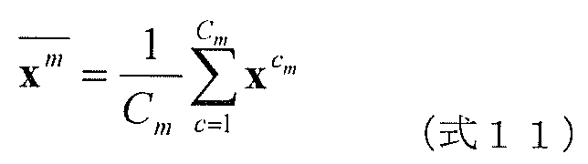
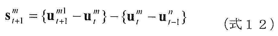
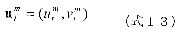
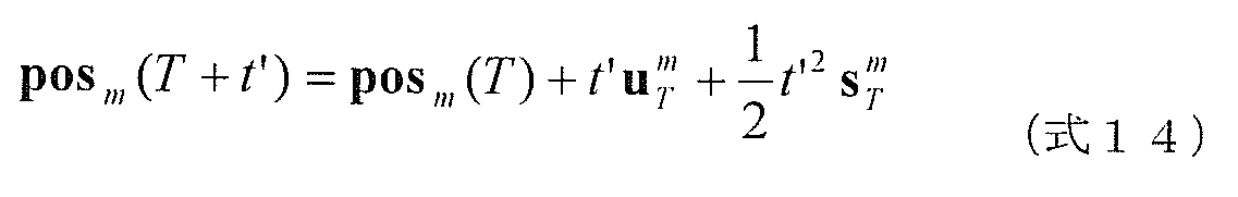
また、さらに、前記領域分割ステップで特定された領域を構成する移動軌跡から、当該領域を代表する移動軌跡を算出し、算出した代表の移動軌跡に従って当該領域が移動すると予測することで、前記移動体の動きを予測する動き予測ステップを含んでもよい。これにより、より精度良く動きを予測することができる。
Furthermore, the movement trajectory representing the area is calculated from the movement trajectory constituting the area specified in the area dividing step, and the movement is predicted by predicting that the area moves according to the calculated representative movement trajectory. A motion prediction step for predicting body motion may be included. Thereby, a motion can be predicted more accurately.
以下、本発明の実施の形態について、図面を用いて説明する。
Hereinafter, embodiments of the present invention will be described with reference to the drawings.
(実施の形態1)
図1は、実施の形態1における移動体検出装置100の構成を示す図である。図1に示されるように、この移動体検出装置100は、画像入力部101、動き解析部102、距離算出部103、領域分割部104、及び出力部105を備える。ここで、領域分割部104は、測地距離算出部106、領域分割候補生成部107、領域間測地距離算出部108、及び領域分割候補選択部109を備える。移動体検出装置100は、複数枚のピクチャを含む動画像中の移動体の全部又は一部の領域を分割することによって動画像中の移動体を検出する装置である。本実施の形態では、移動体検出装置100は、カメラ110で撮影した動画像を取得し、取得した動画像中の移動体を検出し、検出結果に基づいて画像を生成して出力する。ディスプレイ120は、移動体検出装置100から出力される画像を表示する。
(Embodiment 1)
FIG. 1 is a diagram illustrating a configuration of a moving object detection device 100 according to the first embodiment. As illustrated in FIG. 1, the moving body detection apparatus 100 includes an image input unit 101, a motion analysis unit 102, a distance calculation unit 103, a region division unit 104, and an output unit 105. Here, the region dividing unit 104 includes a geodetic distance calculating unit 106, a region dividing candidate generating unit 107, an inter-region geodetic distance calculating unit 108, and a region dividing candidate selecting unit 109. The moving object detection apparatus 100 is an apparatus that detects a moving object in a moving image by dividing all or a part of the region of the moving object in the moving image including a plurality of pictures. In the present embodiment, the moving body detection apparatus 100 acquires a moving image captured by the camera 110, detects a moving body in the acquired moving image, generates an image based on the detection result, and outputs the image. The display 120 displays an image output from the moving object detection apparatus 100.
画像入力部101は、カメラ110等から送られてくる、動画像を構成する時間的に異なる複数枚のピクチャの入力を受け付ける処理部であり、例えば、ビデオカメラ、あるいは、ビデオカメラと接続された通信インターフェース等である。
The image input unit 101 is a processing unit that receives input of a plurality of temporally different pictures that are sent from the camera 110 or the like, and is connected to, for example, a video camera or a video camera. Such as a communication interface.
動き解析部102は、画像入力部101で受け付けられた複数枚のピクチャを構成する1個以上の画素からなるブロックごとに、時間的に隣接する2枚のピクチャ間での画像の動きを検出し、検出した動きを複数枚のピクチャについて連結することで、移動軌跡を算出する処理部である。つまり、ブロックとは、移動軌跡を算出する単位であり、1個以上の画素の集まりである。
The motion analysis unit 102 detects image motion between two temporally adjacent pictures for each block composed of one or more pixels constituting a plurality of pictures received by the image input unit 101. This is a processing unit that calculates a movement trajectory by linking detected motions for a plurality of pictures. That is, a block is a unit for calculating a movement locus, and is a collection of one or more pixels.
距離算出部103は、動画像を構成する複数の画像間の対応点である移動軌跡を複数取得し、取得した移動軌跡について、移動軌跡間の類似度を表す距離を算出する処理部であり、本実施の形態では、移動する物体の形状変化を捉えるために、動き解析部102で算出したブロックiの移動軌跡と、i以外のブロックの移動軌跡とを用いて、ブロックの動きの類似度を表す距離を算出する。よって、I個のブロックの移動軌跡を用いた場合、算出される距離はI行I列(I×I)の距離マトリクスとなる。ここでは、ブロックの動きの類似度を評価する距離を計算することによって、ブロック間の距離が動きによって変化する移動体、特に、関節物体のように形状が変化しながら移動する人物等の物体の動きを距離マトリクスとして表現することが可能である。なお、以降の説明では、ブロックiの移動軌跡を移動軌跡iと呼ぶこととする。このように、本明細書における「距離」は、2次元空間における2点間の距離だけでなく、後述するように、多次元のデータ間の算術的な距離を含み、1つの値、あるいは、複数の値の集合(距離マトリクス)である。なお、距離算出部103は、移動軌跡間の類似度を表す距離として、例えば、複数の画像における移動軌跡間のユークリッド距離の平均値を算出する。
The distance calculation unit 103 is a processing unit that acquires a plurality of movement trajectories that are corresponding points between a plurality of images constituting a moving image, and calculates a distance representing the similarity between the movement trajectories for the acquired movement trajectories. In the present embodiment, in order to capture the shape change of a moving object, the block movement similarity is calculated using the movement locus of block i calculated by the motion analysis unit 102 and the movement locus of blocks other than i. Calculate the distance to represent. Therefore, when the movement trajectory of I blocks is used, the calculated distance is a distance matrix of I rows and I columns (I × I). Here, by calculating the distance that evaluates the similarity of the movement of the blocks, the distance between the blocks is changed by the movement, in particular, an object such as a person who moves while changing its shape like a joint object. It is possible to express movement as a distance matrix. In the following description, the movement locus of block i is referred to as movement locus i. Thus, the “distance” in the present specification includes not only a distance between two points in a two-dimensional space but also an arithmetic distance between multi-dimensional data as described later, one value, or It is a set of multiple values (distance matrix). Note that the distance calculation unit 103 calculates, for example, an average value of Euclidean distances between movement trajectories in a plurality of images as a distance representing the similarity between the movement trajectories.
領域分割部104は、距離算出部103で算出された距離に基づいて、類似する移動軌跡の集まりを1つの領域として特定することによって、領域分割をする処理部である。この領域分割部104は、測地距離算出部106、領域分割候補生成部107、領域間測地距離算出部108及び領域分割候補選択部109を有する。
The region dividing unit 104 is a processing unit that divides a region by specifying a collection of similar movement trajectories as one region based on the distance calculated by the distance calculating unit 103. The area dividing unit 104 includes a geodesic distance calculating unit 106, an area dividing candidate generating unit 107, an inter-area geodetic distance calculating unit 108, and an area dividing candidate selecting unit 109.
領域分割部104を構成する、測地距離算出部106および領域分割候補生成部107は、距離算出部103で算出した距離マトリクスを用いて、移動軌跡間の距離の分布における不連続性を検出し、検出した不連続点よりも小さい距離だけ離れた移動軌跡同士が一つのクラスタとなる領域分割候補を複数生成する。
The geodetic distance calculation unit 106 and the region division candidate generation unit 107 constituting the region division unit 104 detect discontinuity in the distribution of the distance between the movement trajectories using the distance matrix calculated by the distance calculation unit 103, A plurality of region division candidates are generated in which movement trajectories separated by a distance smaller than the detected discontinuous point form one cluster.
具体的には、測地距離算出部106は、領域分割に用いられる判断基準である複数の閾値を生成し、生成した複数の閾値のそれぞれについて、(1)距離算出部103で算出された距離に対して、当該閾値よりも大きい距離を無限大化する非線形化を施し、(2)非線形化後の距離を用いて、動き解析部102が算出した複数の移動軌跡における移動軌跡間の測地距離を算出する。
Specifically, the geodetic distance calculation unit 106 generates a plurality of threshold values that are determination criteria used for area division, and (1) sets the distance calculated by the distance calculation unit 103 for each of the generated threshold values. On the other hand, non-linearization is performed to make the distance larger than the threshold infinite, and (2) the geodesic distance between the movement trajectories in the plurality of movement trajectories calculated by the motion analysis unit 102 is calculated using the distance after the non-linearization. calculate.
領域分割候補生成部107は、測地距離算出部106で生成した複数の閾値のそれぞれの移動軌跡間の測地距離に基づいて、有限の値の測地距離だけ離れた移動軌跡の集まりを領域分割候補とすることで、複数の領域分割候補を生成する。
The area division candidate generation unit 107 determines, as area division candidates, a collection of movement trajectories separated by a finite value of the geodetic distance based on the geodetic distances between the movement trajectories of the plurality of threshold values generated by the geodetic distance calculation unit 106. Thus, a plurality of area division candidates are generated.
領域間測地距離算出部108は、領域分割候補生成部107で算出した複数の領域分割候補に対して、領域分割候補に属する複数の移動軌跡間の測地距離に基づいて、2つ領域分割候補間の類似度を表す領域間測地距離を算出する。
The inter-region geodetic distance calculation unit 108 is configured to determine whether a plurality of region division candidates calculated by the region division candidate generation unit 107 is between two region division candidates based on a geodetic distance between a plurality of movement loci belonging to the region division candidate. The inter-regional geodetic distance representing the degree of similarity is calculated.
領域分割候補選択部109は、領域間測地距離算出部108で算出された領域間測地距離をもとに領域分割候補を選択し、選択した領域分割候補に対応する複数の移動軌跡ごとにクラスタリングすることによって、画像中の移動体の検出と画像の領域分割を行う。具体的には、領域分割候補選択部109は、領域分割候補生成部107で生成された領域分割候補のうち、領域間測地距離算出部108で算出された領域間測地距離が予め定められた条件を満たす領域分割候補を、領域分割の結果として選択する。
The region division candidate selection unit 109 selects a region division candidate based on the inter-region geodetic distance calculated by the inter-region geodetic distance calculation unit 108, and performs clustering for each of the plurality of movement loci corresponding to the selected region division candidate. Thus, detection of a moving body in the image and area division of the image are performed. Specifically, the region division candidate selection unit 109 includes a condition in which the inter-region geodetic distance calculated by the inter-region geodetic distance calculation unit 108 among the region division candidates generated by the region division candidate generation unit 107 is predetermined. A region division candidate that satisfies the above is selected as a result of the region division.
出力部105は、領域分割部104で行った動画像中の移動体の検出結果もしくは、画像の領域分割結果を出力する。具体的には、出力部105は、画像入力部101で受け付けた動画像に対して、例えば、領域分割部104で特定された領域ごとに異なる表示態様となるように、画像処理を施し、ディスプレイ120等に出力する。
The output unit 105 outputs the detection result of the moving object in the moving image performed by the region dividing unit 104 or the region dividing result of the image. Specifically, the output unit 105 performs image processing on the moving image received by the image input unit 101 so that, for example, the display mode is different for each region specified by the region dividing unit 104, and the display Output to 120 etc.
本明細書において、「領域抽出」とは、ある特定の対象物が存在する画像領域を抽出する検出技術と、対象物の区別なく物体ごとに画像領域を分割する領域分割技術の両者を含んでいる。なお、検出技術と領域分割技術とは、共通する部分が多いため、本明細書においては両者を区別しない。
In this specification, “area extraction” includes both a detection technique for extracting an image area where a specific target object exists and an area division technique for dividing an image area for each object without distinguishing the target object. Yes. Note that the detection technique and the area division technique have many common parts, and therefore, they are not distinguished in this specification.
なお、上記した移動体検出装置100を構成する各構成要素(画像入力部101、動き解析部102、距離算出部103、領域分割部104、出力部105)は、コンピュータ上で実行されるプログラム等のソフトウェアで実現されてもよいし、電子回路等のハードウェアで実現されてもよい。
図2は、ソフトウェアによって実現された本実施の形態における移動体検出装置のハードウェア構成を示す図である。図2において、カメラ110は画像を撮影して出力し、コンピュータ1002は画像を取得して領域抽出処理を行って、領域抽出結果を表示する画像を生成する。ディスプレイ120はコンピュータ1002で生成された画像を取得して表示する。コンピュータ1002は、I/F1004、CPU1005、ROM1006、RAM1007、HDD1008、ビデオカード1009で構成される。コンピュータ1002を動作させるプログラムは、ROM1006またはHDD1008にあらかじめ保持されている。プログラムは、プロセッサであるCPU1005によって、ROM1006またはHDD1008からRAM1007に読み出されて展開される。CPU1005はRAM1007に展開されたプログラム中のコード化された各命令を実行する。I/F1004は、プログラムの実行に応じて、カメラ110で撮影された画像を、RAM1007へ取り込む。ビデオカード1009は、プログラムの実行に応じて生成された画像を出力し、ディスプレイ120で表示される。
Note that each component (the image input unit 101, the motion analysis unit 102, the distance calculation unit 103, the region division unit 104, and the output unit 105) included in the above-described moving body detection apparatus 100 is a program executed on a computer or the like. It may be realized by software, or may be realized by hardware such as an electronic circuit.
FIG. 2 is a diagram illustrating a hardware configuration of the moving object detection device according to the present embodiment realized by software. In FIG. 2, the camera 110 captures and outputs an image, and the computer 1002 acquires the image and performs region extraction processing to generate an image that displays the region extraction result. The display 120 acquires and displays an image generated by the computer 1002. A computer 1002 includes an I / F 1004, a CPU 1005, a ROM 1006, a RAM 1007, an HDD 1008, and a video card 1009. A program for operating the computer 1002 is stored in the ROM 1006 or the HDD 1008 in advance. The program is read from the ROM 1006 or the HDD 1008 to the RAM 1007 and expanded by the CPU 1005 which is a processor. The CPU 1005 executes each coded instruction in the program expanded in the RAM 1007. The I / F 1004 captures an image captured by the camera 110 into the RAM 1007 in accordance with the execution of the program. The video card 1009 outputs an image generated according to the execution of the program and is displayed on the display 120.
なお、コンピュータプログラムは、半導体であるROM1006またはHDD1008に格納されるのに限られず、たとえば光ディスクに格納されていてもよい。また、コンピュータプログラムは、有線や無線のネットワーク、放送などを介して伝送され、コンピュータのRAM1007に取り込まれてもよい。
Note that the computer program is not limited to being stored in the ROM 1006 or the HDD 1008, which is a semiconductor, but may be stored in, for example, an optical disc. Further, the computer program may be transmitted via a wired or wireless network, broadcasting, or the like, and may be taken into the RAM 1007 of the computer.
以下、本実施の形態の移動体検出装置100の動作を、図3を用いて説明する。
Hereinafter, the operation of the moving object detection apparatus 100 according to the present embodiment will be described with reference to FIG.
図3は、本実施の形態の移動体検出装置100の動作を表すフローチャートである。
FIG. 3 is a flowchart showing the operation of the moving object detection apparatus 100 of the present embodiment.
図3において、7つのステップS201~S209は、それぞれ図1の各処理部に対応している。すわなち、画像入力部101は画像入力ステップS201、動き解析部102は動き解析ステップS202、距離算出部103は距離算出ステップS203、測地距離算出部106は測地距離算出ステップS204、領域分割候補生成部107は領域分割候補生成ステップS205、領域間測地距離算出部108は領域間測地距離算出ステップS206、領域分割候補選択部109は領域分割候補選択ステップS207、出力部105は画像出力ステップS208の各動作を実行する。領域分割部104は、領域分割ステップS209を実行する。
In FIG. 3, seven steps S201 to S209 correspond to the respective processing units in FIG. In other words, the image input unit 101 is the image input step S201, the motion analysis unit 102 is the motion analysis step S202, the distance calculation unit 103 is the distance calculation step S203, the geodetic distance calculation unit 106 is the geodetic distance calculation step S204, and the region division candidate generation is performed. The section 107 is an area division candidate generation step S205, the inter-area geodesic distance calculation section 108 is an inter-area geodesic distance calculation step S206, the area division candidate selection section 109 is an area division candidate selection step S207, and the output section 105 is an image output step S208. Perform the action. The area dividing unit 104 executes an area dividing step S209.
画像入力ステップS201において、画像入力部101は、カメラ110から、動画像を構成する複数のピクチャを取得する。ここではT枚のピクチャが入力されたものとする。
In image input step S <b> 201, the image input unit 101 acquires a plurality of pictures constituting a moving image from the camera 110. Here, it is assumed that T pictures have been input.
図4は、カメラ110によって撮影される対象物の状況である撮影状況の一例を示す図である。また、図5(a)~図5(f)は、カメラ110によって、図4の撮影状況において撮影された動画像に含まれる複数枚のピクチャの一例を示す図である。画像入力部101は、第1フレームから第TフレームまでのT枚のピクチャをカメラ110から受け付ける。本実施の形態では、ピクチャの数Tは、あらかじめ定められているものとする。
FIG. 4 is a diagram illustrating an example of a shooting situation that is a situation of an object shot by the camera 110. FIGS. 5A to 5F are diagrams showing an example of a plurality of pictures included in a moving image shot by the camera 110 in the shooting state of FIG. The image input unit 101 receives T pictures from the first frame to the Tth frame from the camera 110. In the present embodiment, it is assumed that the number T of pictures is predetermined.
次に、動き解析ステップS202では、動き解析部102は、入力された複数のピクチャ間の動き情報を算出し、移動軌跡を生成して出力する。複数のピクチャ間の動きを算出する手法として、ここでは複数のピクチャのうちのある1つのピクチャ上のI個の画素を基準に、他の(T-1)枚のピクチャ中の対応する画素を探索する。なお、I個の画素の代わりに、I個の小矩形領域(ブロック)を基準にしても良い。例えば、tフレームと(t+1)フレームのピクチャを用いて、tフレームのピクチャ上の画素iの画素座標(xit,yit) (i=1…I)に対応する、(t+1)フレームのピクチャ上の画素座標(xit+1,yit+1)を推定する。ピクチャが3枚以上ある場合は、順次対応する座標を求めていくことで、入力したT枚全てのピクチャのI個の対応点を算出する。
Next, in the motion analysis step S202, the motion analysis unit 102 calculates motion information between a plurality of inputted pictures, generates a movement locus, and outputs it. As a method for calculating the motion between a plurality of pictures, here, with reference to I pixels on one picture of the plurality of pictures, the corresponding pixels in the other (T−1) pictures are calculated. Explore. Note that instead of I pixels, I small rectangular regions (blocks) may be used as a reference. For example, using pictures of t frame and (t + 1) frame, on a picture of (t + 1) frame corresponding to the pixel coordinate (xit, yit) (i = 1... I) of pixel i on the picture of t frame. Estimate pixel coordinates (xit + 1, yit + 1). When there are three or more pictures, I corresponding points of all the inputted T pictures are calculated by sequentially obtaining corresponding coordinates.
上記した複数のピクチャ間の対応点を算出する具体的な手法は、非特許文献1もしくは非特許文献2などに詳しく記載されているため、ここでは詳細の説明を省略する。
The specific method for calculating the corresponding points between a plurality of pictures is described in detail in Non-Patent Document 1 or Non-Patent Document 2, and therefore detailed description thereof is omitted here.
(非特許文献1)P.Anandan,“A Computational Framework and an Algorithm for the Measurement of Visual Motion”,International Journal of Computer Vision,Vol.2,pp.283-310,1989
(非特許文献2)Vladimir Kolmogorov and Ramin Zabih,“Computing Visual Correspondence with Occlusions via Graph Cuts”,International Conference on Computer Vision,2001
(Non-Patent Document 1) Anandan, “A Computational Framework and an Algorithm for the Measurement of Visual Motion”, International Journal of Computer Vision, Vol. 2, pp. 283-310, 1989
(Non-Patent Document 2) Vladimir Kolmogorov and Ramin Zabih, “Computing Visual Correspondence with Occupation via Graph Cuts”, International Conference on Computer Vision 1, 200
そして、この動き解析ステップS202では、動き解析部102は、I個の画素のT枚のピクチャにわたる動き情報である、対応点の画素座標の組から、I個の画素ごとに対応する移動軌跡を、下記式1のように、I個生成する。
In this motion analysis step S202, the motion analysis unit 102 calculates a movement trajectory corresponding to each I pixel from a set of pixel coordinates of corresponding points, which is motion information over T pictures of I pixels. As shown in the following formula 1, I pieces are generated.
ここで、Tは移動軌跡の算出に用いたピクチャの枚数である。
Here, T is the number of pictures used to calculate the movement trajectory.
図6は、移動軌跡xの例を示す図である。移動軌跡xは、時刻tから時刻t+(T-1)の入力画像301において、画素i303に対応する他のピクチャ上へ動き情報302から算出した、画素座標の集まりからなるベクトルである。
FIG. 6 is a diagram illustrating an example of the movement trajectory x. The movement trajectory x is a vector composed of a collection of pixel coordinates calculated from the motion information 302 onto another picture corresponding to the pixel i 303 in the input image 301 from time t to time t + (T−1).
次に、距離算出ステップS203にて、距離算出部103は、複数の移動軌跡を入力として移動軌跡間の距離(ここでは、ユークリッド距離の平均値)を算出する。画素iの移動軌跡と画素jの移動軌跡との距離f(i,j)は、下記式2により算出できる。
Next, in the distance calculation step S203, the distance calculation unit 103 calculates a distance (in this case, an average value of the Euclidean distance) between the movement trajectories by inputting a plurality of movement trajectories. The distance f (i, j) between the movement locus of the pixel i and the movement locus of the pixel j can be calculated by the following equation 2.
なお、本実施の形態において、後述する測地距離gと区別して説明するために、移動軌跡間の距離fを線形距離と呼ぶが、線形距離の定義式を線形演算に限定するものではなく、線形距離の定義式に非線形の演算が含まれていても良い。
In the present embodiment, the distance f between the movement trajectories is referred to as a linear distance in order to distinguish it from the geodetic distance g described later. However, the linear distance defining formula is not limited to a linear calculation, and linear The distance defining formula may include a non-linear calculation.
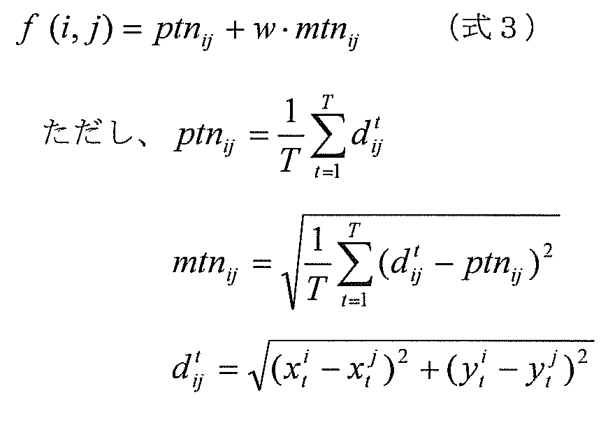
なお、線形距離f(i,j)を算出する式として、上記式2の代わりに下記式3を用いてもよい。
In addition, as a formula for calculating the linear distance f (i, j), the following formula 3 may be used instead of the above formula 2.
ここで、wは重み係数であり、設計者が設定するパラメータである。上記式3の移動軌跡間の距離f(i,j)は、移動軌跡間距離の時間平均値ptnijに、移動軌跡間距離の時間変動成分mtnijを加えたものである。特に移動軌跡間距離の時間変動成分mtnijは、画素の動きの類似度を示すものであり、これによって、画素間のなす距離の関係が時間的に変化しない剛体だけでなく、関節物体等の形状変化を捉えることができる。
Here, w is a weighting coefficient, which is a parameter set by the designer. The distance f (i, j) between the movement trajectories in the above equation 3 is obtained by adding the time fluctuation component mtn ij of the distance between the movement trajectories to the time average value ptn ij of the distance between the movement trajectories. In particular, the time variation component mtn ij of the distance between the movement trajectories indicates the similarity of the movement of the pixels, so that not only the rigid body in which the relationship of the distance between the pixels does not change in time but also the joint object etc. It can capture shape changes.
そして、距離算出部103は、上記式2または上記式3で算出した、I個の移動軌跡間の距離f(i,j)から、下記式4に示されるI×Iの距離マトリクスFを生成する。
Then, the distance calculation unit 103 generates an I × I distance matrix F expressed by the following expression 4 from the distance f (i, j) between the I moving trajectories calculated by the above expression 2 or 3. To do.
続いて、測地距離算出ステップS204では、移動軌跡間の距離の集まりである距離マトリクスFを取得して、移動軌跡の近傍を定義する距離の閾値Rを複数用いて、前記移動軌跡間の距離を測地距離に変換する。つまり、測地距離算出ステップS204では、複数の閾値を取得し、取得した複数の閾値を、移動軌跡の近傍を定義する閾値として用いて、距離算出ステップS203で算出された移動軌跡間の距離から、それぞれの閾値ごとに、近傍にある移動軌跡を辿っていく経路における距離を算出することで、移動軌跡間の測地距離を算出する。そして、移動軌跡間の測地距離が有限である移動軌跡の集まりの情報を含む領域分割候補を複数生成して出力する。
Subsequently, in geodesic distance calculation step S204, a distance matrix F that is a collection of distances between the movement trajectories is acquired, and a plurality of distance threshold values R that define the vicinity of the movement trajectory are used to determine the distance between the movement trajectories. Convert to geodetic distance. That is, in the geodesic distance calculation step S204, a plurality of threshold values are acquired, and the acquired plurality of threshold values are used as threshold values that define the vicinity of the movement locus, and the distance between the movement tracks calculated in the distance calculation step S203 is calculated. The geodetic distance between the movement trajectories is calculated by calculating the distance in the route that follows the movement trajectory in the vicinity for each threshold. Then, a plurality of area division candidates including information on a collection of movement loci with a finite geodetic distance between the movement loci are generated and output.
以降、測地距離算出ステップS204の動作をさらに詳しく説明する。
Hereinafter, the operation of the geodetic distance calculation step S204 will be described in more detail.
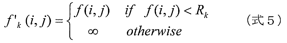
まず、測地距離算出ステップS204では、測地距離算出部106は、上記式2で算出した距離f(i,j)に対してあらかじめ定められたK個の閾値Rkを用いて、それぞれの閾値に対して、下記式5の非線形化処理を行い、f´k(i,j)を算出する。
First, in the geodetic distance calculation step S204, the geodetic distance calculation unit 106 uses K threshold values R k that are predetermined with respect to the distance f (i, j) calculated by the above equation 2, and sets each threshold value. On the other hand, the non-linearization processing of the following formula 5 is performed to calculate f ′ k (i, j).
次に、測地距離算出部106は、非線形化された距離f´k(i,j)を用いて、測地距離を算出する。測地距離とは、複数の点を結ぶノードの距離(長さ)が得られているときに、ある2点間を結び得る全ての経路の距離のうちの最短の距離である。よって、測地距離算出部106は、第1の移動軌跡から第2の移動軌跡までの測地距離の算出においては、距離算出部103で算出された複数の移動軌跡のいずれかを中継点として第1の移動軌跡から第2の移動軌跡に辿りつく全ての経路のうちの最短の経路を、測地距離として、算出する。
Next, the geodetic distance calculation unit 106 calculates a geodetic distance using the non-linearized distance f ′ k (i, j). The geodesic distance is the shortest distance among the distances of all routes that can connect two points when the distance (length) of a node connecting a plurality of points is obtained. Therefore, the geodetic distance calculation unit 106 calculates the geodetic distance from the first movement locus to the second movement locus by using any one of the plurality of movement loci calculated by the distance calculation unit 103 as a relay point. The shortest route among all the routes that reach the second movement locus from the movement locus is calculated as the geodetic distance.
例えば、移動軌跡iと移動軌跡jの2点間を直接結ぶノードの距離f´k(i,j)が得られているとする。このとき移動軌跡iと移動軌跡jの2点間を結ぶ経路は、2点間を直接結ぶノード以外に、別の移動軌跡sをたどる経路もある。この経路の距離をf´k(i,s)+ f´k(s,j)とする。このような複数の経路の距離のうちで、最も短い距離を、下記式6に示されるように、測地距離gk(i,j)とする。
For example, it is assumed that the distance f ′ k (i, j) of the node directly connecting the two points of the movement locus i and the movement locus j is obtained. At this time, the route connecting the two points of the movement locus i and the movement locus j includes a route following another movement locus s other than the node directly connecting the two points. Let the distance of this route be f ′ k (i, s) + f ′ k (s, j). Among the distances of the plurality of routes, the shortest distance is defined as a geodetic distance g k (i, j) as shown in the following formula 6.
上記式6において、min(x,y)は、値xと値yのうち小さい方を返す関数である。また、sは、移動軌跡sであり、移動軌跡iから移動軌跡jに辿(たど)りつくための中継点である。ここで、f´k(i,s)+ f´k(s,j)における中継点sは1点に限るものではない。なお、kは複数の閾値Rkに対応する。
In Equation 6, min (x, y) is a function that returns the smaller one of the value x and the value y. Further, s is a movement trajectory s, which is a relay point for tracing from the movement trajectory i to the movement trajectory j. Here, the relay point s in f ′ k (i, s) + f ′ k (s, j) is not limited to one point. Note that k corresponds to a plurality of threshold values R k .
上述した多次元データ間の測地距離を算出する手法、および、測地距離の算出における2点間の最短経路を探索する手法の詳細は、例えば非特許文献3のISOMAP、非特許文献4のダイクストラ法などが広く知られているため、ここでは処理手順の詳細説明を省略する。
Details of the above-described method for calculating the geodetic distance between multidimensional data and the method for searching for the shortest path between two points in the calculation of the geodetic distance include, for example, ISOMAP of Non-Patent Document 3 and Dijkstra Method of Non-Patent Document 4 For example, the detailed description of the processing procedure is omitted here.
(非特許文献3)Joshua Tenenbaum,Vin de Silva,John Langford,“A Global Geometric Framework for Nonlinear Dimensionality Reduction”,Science,VOL290,pp.2319-2322,22 December,2000
(非特許文献4)E.W.Dijkstra,“A note on two problems in connexion with graphs”,Numerische Mathematik,pp.269-271,1959
(Non-patent literature 3) Joshua Tenenbaum, Vin de Silva, John Langford, “A Global Geometric Framework for Nonlinear Dimensional Reduction”, Science, VOL. 2319-2322, 22 December, 2000
(Non-Patent Document 4) W. Dijkstra, “A note on two probes in connection with graphs”, Numerisch Mathematik, pp. 269-271, 1959
さらに、上記式6で算出した、I個の移動軌跡間の測地距離gk(i,j)から、領域分割候補生成部107は、下記式7に示されるI×Iの測地距離のマトリクスGkを生成する。
Further, from the geodetic distance g k (i, j) between the I movement trajectories calculated by the above equation 6, the region division candidate generation unit 107 calculates an I × I geodetic distance matrix G expressed by the following equation 7. Generate k .
上記した処理によって、測地距離算出ステップS204では、測地距離算出部106は、K個の閾値Rkに対応するK個の測地距離マトリクスGkを生成する。
The process described above, the geodetic distance calculating step S204, the geodesic distance calculation unit 106 generates K pieces of geodesic distance matrix G k corresponding to the K threshold R k.
ここで、上記式5及び上記式6に示した非線形化及び測地距離の算出処理について、図7(a)~図7(c)の概念図を用いて説明する。まず、図7(a)は、上記式1に示される移動軌跡xのデータの分布を、説明の都合上2次元のデータ分布として示したものである。ここで、それぞれのデータ点は、上記式1で示した画素iの移動軌跡に相当する。上記式2で得られる距離f(i,j)の関係を、図7(b)に示す。データ点iとデータ点jとの距離は、データ点iとデータ点sとの距離よりも小さくなる。一方、上記式5及び上記式6に示される測地距離変換を行うと図7(c)に示すように、データ点iとデータ点jとの距離g(i,j)は、データ点を矢印のように中継のデータ点sを辿った距離となる。結果として、距離f(i,j)を用いる場合と異なり、データ点iとデータ点jとの距離g(i,j)は、データ点iとデータ点sとの距離g(i,s)よりも大きくなる。
Here, the non-linearization and geodetic distance calculation processing shown in Equation 5 and Equation 6 will be described with reference to the conceptual diagrams of FIGS. 7 (a) to 7 (c). First, FIG. 7A shows the data distribution of the movement trajectory x shown in the above equation 1 as a two-dimensional data distribution for convenience of explanation. Here, each data point corresponds to the movement trajectory of the pixel i shown in Equation 1 above. The relationship of the distance f (i, j) obtained by the above equation 2 is shown in FIG. The distance between the data point i and the data point j is smaller than the distance between the data point i and the data point s. On the other hand, when the geodetic distance conversion shown in the above formula 5 and the above formula 6 is performed, as shown in FIG. 7C, the distance g (i, j) between the data point i and the data point j indicates that the data point is an arrow. As shown, the distance follows the relay data point s. As a result, unlike the case of using the distance f (i, j), the distance g (i, j) between the data point i and the data point j is the distance g (i, s) between the data point i and the data point s. Bigger than.
次に、このような上記式5及び上記式6に示した測地距離変換の特徴を、図8(a)及び図8(b)の概念図を用いて説明する。ここでは、線形距離f(i,j)と測地距離gk(i,j)の違いを分かりやすく説明するため、上記式2に示すような時刻tにおける移動軌跡間距離を例とする。図8(a)は、線形距離f(i,j)の例である。例えば、頭部の画素i502と手先部の画素j503との距離は、距離501に示す距離となる。一方、上記式5及び上記式6に示される測地距離変換を行うことによって、閾値Rkが適切に設定されている場合、図8(b)に示されるように、頭部の画素i502と手先部の画素j503との距離は、画素s504を通って画素jにたどり着くまでの矢印で示したような距離の和となる。
Next, the characteristics of the geodetic distance conversion shown in the above formulas 5 and 6 will be described with reference to the conceptual diagrams of FIGS. 8A and 8B. Here, in order to explain the difference between the linear distance f (i, j) and the geodetic distance g k (i, j) in an easy-to-understand manner, the distance between the movement trajectories at time t as shown in the above equation 2 is taken as an example. FIG. 8A shows an example of the linear distance f (i, j). For example, the distance between the pixel i 502 at the head and the pixel j 503 at the hand is the distance indicated by the distance 501. On the other hand, when the threshold value R k is appropriately set by performing the geodetic distance conversion shown in the above formulas 5 and 6, as shown in FIG. The distance from the pixel j503 in this part is the sum of the distances indicated by arrows until the pixel j reaches the pixel j through the pixel s504.
そのため、図8(a)に示される距離501では人物のような関節で繋がった形状をデータとして連続的に表現できないのに対して、図8(b)に示される測地距離では、関節が繋がった形状を距離として連続性を表現することが可能となる。
For this reason, at the distance 501 shown in FIG. 8A, the shape connected by a joint like a person cannot be expressed continuously as data, whereas at the geodetic distance shown in FIG. 8B, the joint is connected. It is possible to express continuity using the measured shape as a distance.
また、図8(a)の頭部の画素i502と手先部の画素j503の線形距離は、人物の姿勢の変化に伴って、位置関係が時間的に大きく変化する場合に、その値が時間的に大きく変化する。しかし、同じ2つの移動軌跡間の測地距離gk(i,j)は、類似した動きをする他の移動軌跡との距離の和になるため、線形距離に比べてその変動が小さいという特徴を持つ。
Further, the linear distance between the head pixel i 502 and the hand tip pixel j 503 in FIG. 8A is temporally changed when the positional relationship greatly changes with a change in the posture of the person. Will change greatly. However, the geodetic distance g k (i, j) between the same two movement trajectories is the sum of the distances with other movement trajectories that move in a similar manner, so that the variation is small compared to the linear distance. Have.
さらに、図4や図5中の2名の人物のように、大きく異なる動きをする移動体上の2つの移動軌跡については、軌跡間の線形距離はともに大きな値となり、測地距離はさらに大きな値となる。
Furthermore, for the two movement trajectories on a moving body that moves greatly differently, such as the two persons in FIG. 4 and FIG. 5, the linear distance between the trajectories is a large value, and the geodesic distance is a larger value. It becomes.
以上のことから、人物のように変形しながら移動する移動体を対象とした場合、移動軌跡の距離に基づいて移動体の領域を抽出するためには、線形距離よりも測地距離の方が適していると言える。
Based on the above, when a mobile object that moves while deforming like a person is targeted, a geodetic distance is more suitable than a linear distance to extract the area of the mobile object based on the distance of the movement trajectory. It can be said that.
なお、測地距離算出ステップS204において、線形距離から測地距離を求める手法として、上記式5及び上記式6を用いる手法を示したが、測地距離を求める手法は、この手法に限定されるものではない。
In the geodetic distance calculation step S204, the method using the above formula 5 and the above formula 6 is shown as the method for calculating the geodetic distance from the linear distance. However, the method for calculating the geodetic distance is not limited to this method. .
例えば、あらかじめ定めたK個の閾値Rkの代わりに、あらかじめ定めたK個の閾値Nkを用いる。そして、線形距離f(i,j)から非線形化した距離f´k(i,j)を求める処理として、閾値Rk以上の線形距離f(i,j)を無限大に置き換える上記式5の代わりに、ある移動軌跡iと他の(I-1)個の移動軌跡との線形距離f(i,j)のうちで、小さいほうからNk番目の線形距離よりも大きい線形距離を無限大で置き換えることによって、非線形化した距離f´k(i,j)を算出してもよい。
For example, instead of the predetermined K threshold values R k , the predetermined K threshold values N k are used. Then, as a process for obtaining the non-linearized distance f ′ k (i, j) from the linear distance f (i, j), the linear distance f (i, j) greater than or equal to the threshold R k is replaced with infinity. Instead, among linear distances f (i, j) between a certain movement trajectory i and other (I-1) movement trajectories, a linear distance larger than the N kth linear distance from the smallest is infinite. May be used to calculate a non-linear distance f ′ k (i, j).
次に、領域分割候補生成ステップS205では、領域分割候補生成部107は、測地距離算出部106で算出したK個の閾値Rkに対応するK個の測地距離マトリクスGkに対し、各測地距離マトリクスGk内で連続な移動軌跡間を1つの領域としてまとめることでクラスタリングを行い、クラスタのラベルθとクラスタ数の情報を付与する。ここで2つの移動軌跡が連続とは、移動軌跡iと移動軌跡j間の測地距離gk(i,j)が有限である(無限大ではない)とする。
Next, in the region division candidate generation step S205, the region division candidate generation unit 107 applies each geodetic distance to the K geodetic distance matrices G k corresponding to the K threshold values R k calculated by the geodetic distance calculation unit 106. Clustering is performed by combining continuous movement trajectories in the matrix G k as one region, and information on the cluster label θ and the number of clusters is given. Here, the two movement trajectories are continuous, assuming that the geodetic distance g k (i, j) between the movement trajectory i and the movement trajectory j is finite (not infinite).
K個の閾値Rkに対して得た測地距離を用いたクラスタリングの例を、図9(a)~図9(e)を用いて説明する。ここで、図9(a)は、2人の人物を移動体としたT枚のピクチャを入力として得られたI個の移動軌跡の例を示す図である。なお、この図ではa~hまでの8個の移動軌跡を示しているが、本発明は、移動軌跡の個数を限定するものではなく、移動軌跡の個数はできるだけ多くすることが好ましい。図9(b)は、図9(a)に示した複数の移動軌跡からなる高次元空間の概念図である。説明を容易にするため3次元空間として示しているが、実際には、移動軌跡間の距離を決定するパラメータの個数に依存するので、3次元になるとは限らない。ここで、移動軌跡からなる高次元空間(図9(b))の1点が、それぞれ上記式1に示した一つの移動軌跡に対応する。さらに、高次元空間(図9(b))上で、点と点との距離は、上記式3の距離f(i,j)に対応する。閾値Rkが十分に大きな値である場合、例えば、上記式6においてf(i,j)の最大値よりも閾値Rkが大きい場合には、式5に示される非線形化により、図9(c)に示すように測地距離gk(i,j)は、すべてのi,jの組合せにおいて有限の距離となる。すなわち、不連続点が1点もないためクラスタは1個のクラスタθ1
1となる。一方、閾値Rkが十分に小さい場合、具体的には、上記式5においてf(i,j)の最小値よりも閾値Rkが小さい場合には、上記式5に示される非線形化により、すべてのi,jの組合せにおいてgk(i,j)が無限大となる。すなわち、クラスタ数は移動軌跡の数Iと同数となる。したがって、閾値Rkをf(i,j)の最大値と最小値の間の値に設定し、複数の測地距離マトリクスを算出すると、測地距離マトリクスから1個以上I個以下の異なるクラスタ数をもつクラスタリングの情報、すわなち、移動体の領域抽出の候補を得ることができる。
An example of clustering using the geodetic distances obtained for the K threshold values R k will be described with reference to FIGS. 9 (a) to 9 (e). Here, FIG. 9A is a diagram illustrating an example of I moving trajectories obtained by inputting T pictures having two persons as moving bodies. In this figure, eight movement trajectories from a to h are shown, but the present invention does not limit the number of movement trajectories, and it is preferable to increase the number of movement trajectories as much as possible. FIG. 9B is a conceptual diagram of a high-dimensional space composed of a plurality of movement loci shown in FIG. Although it is shown as a three-dimensional space for ease of explanation, in reality, it depends on the number of parameters for determining the distance between the movement trajectories, and therefore it is not necessarily three-dimensional. Here, one point in the high-dimensional space (FIG. 9B) composed of the movement trajectory corresponds to one movement trajectory represented by the above-described equation 1. Further, on the high-dimensional space (FIG. 9B), the distance between the points corresponds to the distance f (i, j) in the above equation 3. When the threshold value R k is a sufficiently large value, for example, when the threshold value R k is larger than the maximum value of f (i, j) in the above-described equation 6, the non-linearization shown in the equation 5 causes the FIG. As shown in c), the geodetic distance g k (i, j) is a finite distance in all combinations of i, j. That is, since there is no discontinuous point, the cluster becomes one cluster θ 1 1 . On the other hand, when the threshold value R k is sufficiently small, specifically, when the threshold value R k is smaller than the minimum value of f (i, j) in the above equation 5, the non-linearization shown in the above equation 5 For all i, j combinations, g k (i, j) is infinite. That is, the number of clusters is the same as the number I of movement trajectories. Therefore, when the threshold R k is set to a value between the maximum value and the minimum value of f (i, j) and a plurality of geodetic distance matrices are calculated, the number of different clusters of 1 or more and I or less from the geodetic distance matrix is calculated. It is possible to obtain clustering information, that is, candidates for moving object region extraction.
閾値Rkをf(i,j)の最大値と最小値の間の値に設定した場合のクラスタリングについて、図9(d)に示される例について説明する。図9(b)において、移動軌跡aと移動軌跡bとの距離をf(a,b)とした時に、f(d,e) > f(e,g)であるとする。ここでは、閾値をR1として設定した場合に、距離f(d,e)は、閾値R1よりも大きな値を持つ(つまり、f(d,e)>R1)とする。この場合、上記式5に示される非線形化により、上記式6によって測地距離を求めてもg1(d,e)は無限大となる。そこで、領域分割候補生成部107は、移動軌跡dと移動軌跡eとの間を不連続と判定する。この結果、移動軌跡a、b、c、d間の測地距離は不連続点を通らないため有限の値を取り、移動軌跡a、b、c、dから移動軌跡e、f、g、hの測地距離は、すべて無限大となる。このように、領域分割候補生成部107は、測地距離が有限な複数の移動軌跡の組を同じクラスタとし、無限大となる場合は別のクラスタとする。これによって、図9(c)に示される1つのクラスタθ1
1(a、b、c、d、e、f、g、hの組)は、図9(d)に示されるようにθ1
2(e、f、g、hの組)、θ2
2(a、b、c、dの組)の2つのクラスタに分離することができる。さらに、図9(e)に示すように、閾値R2をR1>R2>f(e,g)とした場合に、g1(d,e)は変わらずに(つまり、無限大のまま)、g2(e,g), g2(e,h), g2(f,g), g2(f,h)が無限大になったとする。すると、領域分割候補生成部107は、それぞれ移動軌跡eと移動軌跡gとの間、移動軌跡eと移動軌跡hとの間、移動軌跡fと移動軌跡gとの間、及び、移動軌跡fと移動軌跡hとの間が不連続点であると判定し、図9(d)の場合と同様に測地距離が無限大となる組と無限大にならない組とを整理して、θ1
3(g、hの組)、θ2
3(a、b、c、dの組)、θ3
3(e、fの組)の合計3つのクラスタに分離する。以上の処理によって、測地距離が無限大とならない移動軌跡の組は連続とすることで同じクラスタと判定することができ、測地距離が無限大となる移動軌跡の組は不連続とすることによって、不連続点をもとにクラスタを分離することができる。
An example shown in FIG. 9D will be described for clustering when the threshold value R k is set to a value between the maximum value and the minimum value of f (i, j). In FIG. 9B, when the distance between the movement locus a and the movement locus b is f (a, b), it is assumed that f (d, e)> f (e, g). Here, when the threshold value is set as R 1, the distance f (d, e) is than the threshold R 1 having a large value (i.e., f (d, e)> R1) and. In this case, g 1 (d, e) becomes infinite even if the geodetic distance is obtained by the above equation 6 due to the non-linearization shown in the above equation 5. Therefore, the region division candidate generation unit 107 determines that the distance between the movement locus d and the movement locus e is discontinuous. As a result, the geodesic distance between the movement trajectories a, b, c, and d does not pass through the discontinuous points, and thus takes a finite value. From the movement trajectories a, b, c, d, the movement trajectories e, f, g, h Geodesic distances are all infinite. As described above, the region division candidate generation unit 107 sets a plurality of sets of movement trajectories having finite geodetic distances as the same cluster, and sets them as different clusters when they become infinite. Accordingly, one cluster θ 1 1 (a set of a, b, c, d, e, f, g, and h) shown in FIG. 9C becomes θ 1 as shown in FIG. 9D. 2 (set of e, f, g, h) and θ 2 2 (set of a, b, c, d) can be separated into two clusters. Further, as shown in FIG. 9 (e), when the threshold value R 2 is R 1 > R 2 > f (e, g), g 1 (d, e) remains unchanged (that is, infinite) ), G 2 (e, g), g 2 (e, h), g 2 (f, g), and g 2 (f, h) are infinite. Then, the area division candidate generation unit 107 is respectively between the movement locus e and the movement locus g, between the movement locus e and the movement locus h, between the movement locus f and the movement locus g, and between the movement locus f and It is determined that there is a discontinuity between the movement trajectory h, and as in the case of FIG. 9D, a group in which the geodetic distance is infinite and a group in which the geodesic distance is not infinite are arranged, and θ 1 3 ( g, h), θ 2 3 (a, b, c, d), and θ 3 3 (e, f) are divided into a total of three clusters. By the above processing, a set of movement trajectories where the geodetic distance is not infinite can be determined as the same cluster by making it continuous, and a set of movement trajectories where the geodetic distance is infinite is made discontinuous, Clusters can be separated based on discontinuities.
なお、閾値Rkの設定方法については、f(i,j)の最小値から最大値の間を均等にK個設定しても良いし、f(i,j)の平均値やメディアンを中心に一定間隔で増加、減少させた値を用いても良い。
As for the setting method of the threshold value R k , K values may be set equally between the minimum value and the maximum value of f (i, j), or the average value or median of f (i, j) is the center. Alternatively, a value increased or decreased at regular intervals may be used.
上記した処理によって、領域分割候補生成ステップS205では、領域分割候補生成部107は、K個の測地距離マトリクスGkに対応して、連続した移動軌跡であることを示すクラスタのラベルθk
mの情報と、クラスタ数Mkを生成する。以降のステップでは、この複数の測地距離マトリクスと対応付けられた各クラスタの情報を、ピクチャ中の移動体の領域を示す複数の候補である領域分割候補として扱う。
With the above processing, in the region division candidate generation step S205, the region division candidate generation unit 107 corresponds to the K geodetic distance matrixes G k and has the cluster labels θ k m indicating the continuous movement trajectories. Information and the number of clusters M k are generated. In the subsequent steps, information on each cluster associated with the plurality of geodetic distance matrices is handled as a region division candidate which is a plurality of candidates indicating the region of the moving object in the picture.
次に、領域間測地距離算出ステップS206では、領域間測地距離算出部108は、領域分割候補生成ステップS205で生成された領域分割候補の情報、すわなち、K個の測地距離マトリクスgk(i,j)とそれに対応するクラスタのラベルθk
m、クラスタ数Mkの情報を入力として、複数の領域分割候補に対応する領域間測地距離を算出する。
Next, in the inter-regional geodetic distance calculation step S206, the inter-regional geodetic distance calculation unit 108 performs information on the area division candidates generated in the area division candidate generation step S205, that is, K geodetic distance matrices g k ( i, j) and the corresponding cluster label θ k m and the number of clusters M k are input, and the inter-region geodetic distance corresponding to the plurality of region division candidates is calculated.
以降、領域間測地距離算出ステップS206での領域間測地距離算出部108の動作をさらに詳しく説明する。
Hereinafter, the operation of the inter-region geodetic distance calculation unit 108 in the inter-region geodetic distance calculation step S206 will be described in more detail.
まず、領域間測地距離算出ステップS206では、領域間測地距離算出部108は、K個の閾値Rkに対応する測地距離マトリクスgk(i,j)から、クラスタ数M(Mは2以上)ごとに任意に1つを選択して、これをクラスタ数Mを代表する代表測地距離マトリクスGMとする。本実施の形態1では、代表測地距離マトリクスを選択する方法として、クラスタ数がMである複数の測地距離マトリクスのうち、閾値Rkがもっとも大きいものを選択するものとする。
First, in the inter-region geodesic distance calculation step S206, the inter-region geodesic distance calculation unit 108 calculates the number of clusters M (M is 2 or more) from the geodesic distance matrix g k (i, j) corresponding to the K threshold values R k. One is arbitrarily selected for each, and this is set as a representative geodetic distance matrix G M representing the number M of clusters. In the first embodiment, as a method for selecting a representative geodetic distance matrix, the one having the largest threshold Rk is selected from a plurality of geodetic distance matrices having M clusters.
次に、領域間測地距離算出部108は、クラスタ数Mの代表測地距離マトリクスGMに対して、Mの次にクラスタ数の少ない複数の測地距離マトリクスから任意に1つを選択し、これをクラスタ数Mの参照マトリクスGrMとする。本実施の形態1では、参照マトリクスを選択する方法として、Mの次にクラスタ数の少ない複数の測地距離マトリクスのうち、閾値Rkがもっとも小さいものを選択するものとする。
Next, the inter-region geodetic distance calculation unit 108 selects one arbitrarily from a plurality of geodetic distance matrices with the fewest clusters after M, for the representative geodetic distance matrix GM with the number of clusters M, and selects this. A reference matrix Gr M with M clusters is assumed. In the first embodiment, as a method for selecting a reference matrix, the one having the smallest threshold R k is selected from a plurality of geodetic distance matrices having the smallest number of clusters next to M.
図10(a)~図10(f)に、領域間測地距離算出ステップS206で生成した、測地距離マトリクスGkと、代表測地距離マトリクスGMの例を示す。図10(a)はK個の閾値Rkに対して得た測地距離マトリクスGkの例を示す図である。測地距離マトリクスは、移動軌跡の測地距離gk(i,j)をi行j列の要素とする、I×Iの測地距離の行列である。図10(b)~図10(d)は、それぞれ、クラスタ数1~3の代表測地距離マトリクスGMの例を示す図である。ここでは図10(b)~図10(d)の代表測地距離マトリクスの行、列に対応する移動軌跡は、すべて共通であるものとする。
Figure 10 (a) ~ FIG 10 (f), generated in the region between the geodetic distance calculating step S206, shows the geodesic distance matrix G k, an example of the representative geodesic distance matrix G M. FIG. 10A is a diagram illustrating an example of a geodetic distance matrix G k obtained for K threshold values R k . The geodetic distance matrix is an I × I geodetic distance matrix in which the geodetic distance g k (i, j) of the movement locus is an element of i rows and j columns. Figure 10 (b) ~ FIG 10 (d) are diagrams showing an example of a representative geodesic distance matrix G M clusters C 1-3. Here, it is assumed that the movement trajectories corresponding to the rows and columns of the representative geodetic distance matrixes of FIGS. 10B to 10D are all common.
図10(b)と図9(c)、図10(c)と図9(d)、図10(d)と図9(e)は、それぞれクラスタ数が1~3の場合の代表測地距離マトリクス、及び、移動軌跡の距離の高次元空間の概念図である。
10 (b) and FIG. 9 (c), FIG. 10 (c) and FIG. 9 (d), FIG. 10 (d) and FIG. 9 (e) are representative geodesic distances when the number of clusters is 1 to 3, respectively. It is a conceptual diagram of the high-dimensional space of the distance of a matrix and a movement locus.
図10(b)~図10(d)の矩形の斜線部は、有限の値をもち、これは対応する移動軌跡が連続であり、1つのクラスタを構成することを表している。また、図中の斜線部以外の領域は、距離は無限大となり、対応する移動軌跡が不連続であることを表している。したがって、クラスタ数Mに応じて、対角部にM個の有限距離のクラスタ(M個の斜線部)が並ぶ配置となっている。
10 (b) to 10 (d) have a finite value, which indicates that the corresponding movement trajectory is continuous and forms one cluster. In addition, the area other than the shaded area in the figure indicates that the distance is infinite and the corresponding movement locus is discontinuous. Therefore, in accordance with the number of clusters M, M finite distance clusters (M hatched portions) are arranged in a diagonal portion.
図10(e)及び図10(f)は、参照マトリクスの例を示す図である。クラスタ数Mの参照マトリクスは、クラスタ数がM未満のうち最大のクラスタ数となる測地距離マトリクスから選ばれる。そのため、代表測地距離マトリクスにおいて無限大となる要素が、参照マトリクスにおいては有限の値となる箇所がある。
FIG. 10E and FIG. 10F are diagrams showing examples of reference matrices. The reference matrix for the number of clusters M is selected from a geodetic distance matrix that is the maximum number of clusters out of the number M of clusters. Therefore, there are places where elements that are infinite in the representative geodetic distance matrix have finite values in the reference matrix.
以降、あるクラスタ数がMの代表測地距離マトリクスと参照マトリクスが含む情報について、図11(a)~図11(d)を用いて詳しく説明する。
Hereinafter, the information included in the representative geodetic distance matrix having a certain number of clusters M and the reference matrix will be described in detail with reference to FIGS. 11 (a) to 11 (d).
図11(a)及び図11(b)は、それぞれ、クラスタ数2(M=2)の場合の代表測地距離マトリクス(図11(a))と参照マトリクス(図11(b))の例を示す図である。代表測地距離マトリクスのクラスタθ1
2、θ2
2に対応する、参照マトリクスのクラスタを同様にθ1
2、θ2
2とする(図11(b)に示される2つの斜線領域)。また、代表測地距離マトリクスにおいては値が無限大であり、かつ参照マトリクスにおいては値が有限となる要素の領域(図11(b)中の2つの縦線領域)をθ1,2
2とする。
11 (a) and 11 (b) show examples of the representative geodetic distance matrix (FIG. 11 (a)) and the reference matrix (FIG. 11 (b)) when the number of clusters is 2 (M = 2). FIG. Similarly, the reference matrix clusters corresponding to the clusters θ 1 2 and θ 2 2 of the representative geodetic distance matrix are denoted by θ 1 2 and θ 2 2 (two hatched areas shown in FIG. 11B). In addition, an element region (two vertical line regions in FIG. 11B) whose value is infinite in the representative geodetic distance matrix and whose value is finite in the reference matrix is defined as θ 1,2 2 . .
このとき、参照マトリクスのθ1
2領域はクラスタθ1
2内の移動軌跡間の距離を、θ2
2領域はクラスタθ2
2内の移動軌跡間の距離を、それぞれ表す。また、参照マトリクスの2つのθ1,2
2の領域は、異なるクラスタθ1
2、θ2
2に存在する移動軌跡間の距離を表す。このことから、参照マトリクスのθ1
2内の距離の平均値によってクラスタθ1
2の分布のばらつき度合いを、参照マトリクスのθ2
2内の距離の平均値によってクラスタθ2
2の分布のばらつき度合いを、それぞれ表すことができると言える。さらに、参照マトリクスのθ1,2
2内の距離の平均値によってクラスタθ1
2とθ2
2間の距離を表すことができる。
In this case, theta 1 2 area of the reference matrix to the distance between the moving locus of the cluster theta 1 2, the distance between the moving locus of theta 2 2 region cluster theta 2 in 2, represents respectively. Further, the two θ 1,2 2 regions of the reference matrix represent the distances between the movement trajectories existing in different clusters θ 1 2 and θ 2 2 . Therefore, the distribution variation of the cluster θ 1 2 is determined by the average value of the distance in the reference matrix θ 1 2 , and the distribution variation of the cluster θ 2 2 is determined by the average value of the distance in the reference matrix θ 2 2 . Can be expressed respectively. Furthermore, the distance between the clusters θ 1 2 and θ 2 2 can be represented by the average value of the distances in θ 1,2 2 of the reference matrix.
クラスタ数が2以外の場合でも同様である。例えば、クラスタ数3(M=3)の場合の代表測地距離マトリクス(図11(c))と参照マトリクス(図11(d))の例においても、代表測地距離マトリクスのクラスタθ1
3、θ3
3と参照マトリクスθ1,3
3の間で、上記と同じ関係が成り立つ。
The same applies when the number of clusters is other than two. For example, in the example of the representative geodetic distance matrix (FIG. 11 (c)) and the reference matrix (FIG. 11 (d)) when the number of clusters is 3 (M = 3), clusters θ 1 3 and θ of the representative geodetic distance matrix are used. The same relationship is established between 3 3 and the reference matrix θ 1,3 3 .
以上のような代表測地距離マトリクスと参照マトリクスが含む情報を利用し、領域間測地距離算出ステップS206では、領域間測地距離算出部108は、クラスタ間の距離の指標である領域間測地距離を算出する。
Using the information included in the representative geodetic distance matrix and the reference matrix as described above, in the inter-regional geodetic distance calculation step S206, the inter-regional geodetic distance calculation unit 108 calculates the inter-regional geodetic distance that is an index of the distance between the clusters. To do.
具体的には、クラスタ数Mの代表測地距離マトリクスGMと参照マトリクスGrMから、代表測地距離マトリクスGMでは無限大であり、かつ、参照マトリクスGrMでは有限となる要素に対応する領域θp,q
M、および、クラスタθp
M、θq
Mを抽出する。
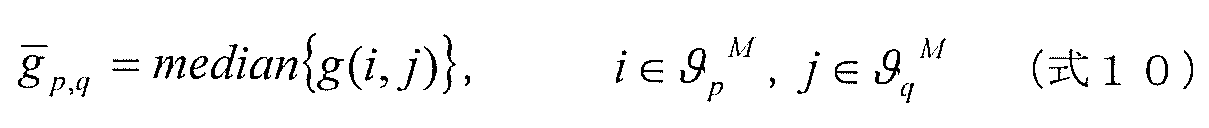
Specifically, from the reference matrix Gr M representative geodesic distance matrix G M cluster number M, representative geodesic distance is a matrix G infinity in M, and the reference matrix Gr area corresponding to the finite element in M theta p, q M and clusters θ p M and θ q M are extracted.
そして、領域間測地距離算出部108は、クラスタθp
M、θq
M間の領域間測地距離hp,q
Mを下記式8により算出する。
Then, the inter-region geodetic distance calculation unit 108 calculates the inter-region geodetic distance h p, q M between the clusters θ p M and θ q M by the following equation (8).
上記式8において、g_M
pは、2つの領域分割候補に対応する2つのクラスタθp
M、θq
Mのうち、クラスタθp
M内の複数の移動軌跡間の測地距離の平均値である。同様に、g_M
qは、クラスタθq
M内の複数の移動軌跡間の測地距離の平均値である。g_M
p,qは、クラスタθp
Mに存在する移動軌跡とクラスタθq
Mに存在する移動軌跡との間の測地距離の平均値である。npおよびnqは、クラスタθp
Mおよびθq
Mに属する移動軌跡の個数である。
In Expression 8, g_M p is an average value of geodesic distances between a plurality of movement loci in the cluster θ p M among the two clusters θ p M and θ q M corresponding to the two region division candidates. . Similarly, g_M q is an average value of geodesic distances between a plurality of movement loci in the cluster θ q M. g _M p, q is the average value of the geodetic distance between the movement trajectory that exists in the trajectory and cluster theta q M of a cluster theta p M. n p and n q are the number of movement trajectories belonging to the clusters θ p M and θ q M.
なお、g_M
p、g_M
q、g_M
p,qは、いずれも参照マトリクスGrMを用いて計算してもよいし、g_M
pおよびg_M
qは、代表測地距離マトリクスGMを、g_M
p,qは参照マトリクスGrMをそれぞれ用いて計算しても良い。
Incidentally, g _M p, g _M q , g _M p, q may be calculated either using the reference matrix Gr M, g _M p and g _M q is representative geodesic distance matrix G M, g _M p, q may be calculated using the reference matrix Gr M respectively.
領域間測地距離算出ステップS206では、領域間測地距離算出部108は、上記した処理を、クラスタ数Mのうち1を除く、算出された全てのクラスタ数に対して行い、それぞれ領域間測地距離hp,q
Mを算出し、対応するクラスタθp
M、θq
M(移動軌跡のラベル情報)を領域分割候補としてあわせて出力する。
In the inter-regional geodetic distance calculation step S206, the inter-regional geodetic distance calculation unit 108 performs the above-described processing on all the calculated cluster numbers excluding 1 out of the cluster number M. p and q M are calculated, and the corresponding clusters θ p M and θ q M (label information of the movement trajectory) are output together as region division candidates.
なお、ある1つのクラスタ数Mの代表測地距離マトリクスGMと参照マトリクスGrMに対し、上記したθp,q
M、θp
M、θq
Mの領域が1組とは限らない。2組以上ある場合においても、上記式8に示される処理により、領域間測地距離を算出する。
Note that the above-described regions of θ p, q M , θ p M , and θ q M are not necessarily one set for a representative geodetic distance matrix G M and a reference matrix Gr M of a certain number of clusters M. Even when there are two or more sets, the inter-region geodetic distance is calculated by the processing shown in the above equation 8.
ここで、上記式8に示される領域間測地距離の性質について説明する。上記式8から、領域間測地距離は、異なる2つの領域分割候補に属する移動軌跡間の測地距離の平均値であるg_M
p,qを、同一領域分割候補内の移動軌跡間の測地距離の平均値であるg_M
p、g_M
qで正規化した値となっている。言い換えると、領域間測地距離は、領域分割候補間の距離を表す指標を領域分割候補内のばらつきを表す指標で正規化した値となっている。そのため、領域間測地距離は、定性的には以下の性質を持つ。
・2つの領域分割候補の間の距離が大きくなるほど、領域間測地距離も大きくなる。
・移動軌跡全体の大きさ(拡縮率)が変化する場合は、領域間測地距離は一定になる。
・移動体の変形によって、領域分割候補内の移動軌跡間の距離が変動しても、領域間測地距離はあまり変わらない。
Here, the nature of the inter-region geodesic distance represented by the above equation 8 will be described. From the above equation 8, the inter-region geodetic distance is calculated by using g_M p, q which is the average value of the geodetic distances between the movement trajectories belonging to two different region division candidates as the geodetic distance between the movement trajectories in the same region division candidate. an average value g _M p, has a normalized value in g _M q. In other words, the inter-region geodetic distance is a value obtained by normalizing an index representing the distance between the region division candidates with an index representing variation within the region division candidates. Therefore, the geodesic distance between regions has the following properties qualitatively.
-The greater the distance between two region division candidates, the greater the inter-region geodetic distance.
-When the size of the entire movement trajectory (scale rate) changes, the inter-regional geodesic distance is constant.
-Even if the distance between the movement trajectories in the region division candidate varies due to the deformation of the moving object, the inter-region geodetic distance does not change much.
このように、領域間測地距離算出部108は、複数の閾値のそれぞれに対して領域分割候補生成ステップS205で生成された複数の領域分割候補のセットのうちの第1の領域分割候補のセットにおける2つの領域分割候補間の類似度として、当該2つの領域分割候補における測地距離である代表測地距離と、当該第1の領域分割候補のセットに含まれる領域分割候補の総数よりも次に小さい総数だけ領域分割候補が含まれる第2の領域分割候補のセットにおける測地距離である参照測地距離とを用いて、予め定められた演算をすることで、領域間測地距離を算出する。つまり、参照測地距離マトリクスに含まれる領域分割候補間の測地距離を、代表測地距離マトリクスに含まれる領域分割候補の各領域内の測地距離で正規化する。言い換えると、参照測地距離と代表測地距離に基づいて、2つの領域分割候補間の距離を表す指標と、各領域分割候補内のばらつきを表す指標とを算出し、その距離を表す指標を、そのばらつきを表す指標で正規化する演算をすることで、領域間測地距離を算出する。
As described above, the inter-region geodetic distance calculation unit 108 uses the first region division candidate set of the plurality of region division candidate sets generated in the region division candidate generation step S205 for each of the plurality of threshold values. As a similarity between two area division candidates, a total number smaller than a representative geodetic distance which is a geodetic distance in the two area division candidates and a total number of area division candidates included in the first area division candidate set. The inter-region geodetic distance is calculated by performing a predetermined calculation using the reference geodetic distance that is the geodetic distance in the second set of region division candidates including only the region division candidates. That is, the geodetic distance between the area division candidates included in the reference geodetic distance matrix is normalized with the geodetic distance in each area of the area division candidates included in the representative geodetic distance matrix. In other words, based on the reference geodetic distance and the representative geodetic distance, an index representing the distance between the two area division candidates and an index representing the variation within each area division candidate are calculated, and the index representing the distance is calculated as An inter-region geodetic distance is calculated by performing an operation of normalizing with an index representing variation.
なお、領域分割候補生成ステップS205で生成される複数の領域分割候補のうち、少なくとも1つの領域分割候補は1個の移動軌跡が属するものであってもよい。このとき、領域間測地距離算出ステップS206では、1個の移動軌跡が属する領域分割候補と他の領域分割候補との領域間測地距離として、その1個の移動軌跡と他の領域分割候補に属する任意の1つの移動軌跡との測地距離を出力すればよい。
It should be noted that at least one region division candidate among the plurality of region division candidates generated in the region division candidate generation step S205 may belong to one movement locus. At this time, in the inter-region geodesic distance calculation step S206, the inter-region geodesic distance between the region division candidate to which one movement locus belongs and the other region division candidates belong to the one movement locus and other region division candidates. What is necessary is just to output the geodetic distance with arbitrary one movement locus | trajectory.
次に、領域分割候補選択ステップS207では、領域分割候補選択部109は、領域分割候補生成部107で生成された複数のクラスタθp
M、θq
Mを領域分割候補とし、その評価値として、領域間測地距離算出部108で算出された領域間測地距離hp,q
Mを扱い、領域間測地距離に基づいてクラスタθp
M、θq
Mの領域分割候補を別個のクラスタとして分割するか否かを選択する。
Next, in the region division candidate selection step S207, the region division candidate selection unit 109 sets the plurality of clusters θ p M and θ q M generated by the region division candidate generation unit 107 as region division candidates, and the evaluation values thereof are as follows: Whether the inter-region geodesic distance h p, q M calculated by the inter-region geodesic distance calculating unit 108 is handled, and the region division candidates of the clusters θ p M , θ q M are divided as separate clusters based on the inter-region geodesic distance Choose whether or not.
具体的には、領域間測地距離hp,q
Mが、あらかじめ定められた閾値Htより大きい場合、対応する2つのクラスタθp
M、θq
Mは、その領域間の距離が十分離れているクラスタとして選択し、個別のクラスタとして確定する。一方、領域間測地距離hp,q
Mが、あらかじめ定められた閾値Htより小さい場合、対応する2つのクラスタθp
M、θq
Mは、同一のクラスタとして確定する。つまり、この場合には、分割しないと確定する。そして、領域分割候補の全てのクラスタに対して、分割するか否かを判定した後、異なるクラスタに属する移動軌跡には異なるラベルθmを割り当て、移動軌跡のクラスタリング情報として出力する。
Specifically, when the inter-region geodetic distance h p, q M is larger than a predetermined threshold Ht, the corresponding two clusters θ p M , θ q M are sufficiently separated from each other. Select as a cluster and confirm as an individual cluster. On the other hand, when the inter-region geodesic distance h p, q M is smaller than a predetermined threshold value Ht, the corresponding two clusters θ p M and θ q M are determined as the same cluster. That is, in this case, it is decided not to divide. Then, for every cluster region segmentation candidate, after determining whether to split assigns different labels theta m to movement locus belonging to different clusters, and outputs as the clustering information of the movement trajectory.
例えば、図11(a)に示されるクラスタ数2の代表測地距離マトリクスと、図11(b)に示される参照マトリクスから算出された領域間測地距離をh1,2
2とし、図11(c)に示されるクラスタ数3の代表測地距離マトリクス、図11(d)に示される参照マトリクスから算出された領域間測地距離をh1,3
3、他のクラスタ数wの領域間測地距離をhp,q
wとする。ここで、h1,2
2>Htで、かつ、h1,3
3、 hp,q
w<Htであるとすると、対応するクラスタθ1
2、θ2
2は、このように分割され、他のクラスタは分割されない(つまり、θ1
2がさらにθ1
3、θ3
3に分割されることはない)。その結果、移動軌跡はクラスタθ1
2、θ2
2の2つのクラスタに分割され、図9(d)と同様なクラスタリング結果を得る。
For example, the representative geodesic distance matrix of the cluster number 2 shown in FIG. 11 (a), the region between the geodesic distance calculated from the reference matrix shown in FIG. 11 (b) and h 1, 2 2, FIG. 11 (c ), The geodesic distance matrix with three clusters shown in FIG. 11, the geodesic distance between regions calculated from the reference matrix shown in FIG. 11D is h 1,3 3 , and the geodesic distance between regions with other cluster numbers w is h Let p, q w . Here, assuming that h 1,2 2 > Ht and h 1,3 3 , h p, q w <Ht, the corresponding clusters θ 1 2 and θ 2 2 are divided in this way, Other clusters are not divided (that is, θ 1 2 is not further divided into θ 1 3 and θ 3 3 ). As a result, the movement trajectory is divided into two clusters of clusters θ 1 2 and θ 2 2 , and a clustering result similar to that shown in FIG. 9D is obtained.
最後に、画像出力ステップS208において、出力部105は、移動軌跡のクラスタθ1
2、θ2
2から、画像を生成して、ディスプレイ120に表示する。
Finally, in the image output step S208, the output unit 105 generates an image from the movement locus clusters θ 1 2 and θ 2 2 and displays the image on the display 120.
ここで、画像出力ステップS208では、出力部105は、I個の移動軌跡に対し、対応するクラスタθ1
2、θ2
2によって異なる色を選択し、選択した色でそれぞれT番目の画像座標位置の画素を描画することで、画像を生成する。
Here, in the image output step S208, the output unit 105 selects different colors for the I movement trajectories according to the corresponding clusters θ 1 2 and θ 2 2 , and each of the Tth image coordinate positions for the selected colors. An image is generated by drawing the pixels.
図12に画像出力ステップS208で生成した画像の例を示す。クラスタリングした移動軌跡ごとに異なる色を持つ画像が表示されることとなる。
FIG. 12 shows an example of the image generated in the image output step S208. An image having a different color for each clustered movement locus is displayed.
なお、画像出力ステップS208において、クラスタリングしたI個の移動軌跡に基づいて画像を生成する手順として、I個の移動軌跡の画像座標位置の画素をクラスタに応じた色で描画するとしたが、画像を生成する方法をこれに限定するものではない。
In the image output step S208, as a procedure for generating an image based on the clustered I movement trajectories, the pixel at the image coordinate position of the I movement trajectories is drawn in a color corresponding to the cluster. The generation method is not limited to this.
具体的には、移動軌跡の数Iと画像全体の画素数とが同数であれば、上述した方法により画像中の全画素をクラスタに応じた色で描画することができる。一方、移動軌跡の数Iが画像全体の画素数より少ない場合、どの移動軌跡の画像座標位置とも一致しない画素が存在する。このような移動軌跡の画像座標位置と一致しない画素については、別の方法で描画しても良い。
Specifically, if the number I of the movement trajectory is the same as the number of pixels of the entire image, all the pixels in the image can be drawn with a color corresponding to the cluster by the method described above. On the other hand, when the number I of movement trajectories is smaller than the number of pixels of the entire image, there are pixels that do not match the image coordinate position of any movement trajectory. Such a pixel that does not coincide with the image coordinate position of the movement locus may be drawn by another method.
例えば、動き解析部102において、ある移動軌跡を生成するための動き検出に用いたブロックに属する画素は、その移動軌跡のクラスタと同じ色で描画するとしても良い。
For example, in the motion analysis unit 102, pixels belonging to a block used for motion detection for generating a certain movement locus may be drawn in the same color as the cluster of the movement locus.
また、移動軌跡の画像座標位置と一致しない画素を描画する別の方法として、最近傍の移動軌跡のクラスタと同じ色で描画するとしても良い。
Also, as another method of drawing a pixel that does not match the image coordinate position of the movement locus, it may be drawn in the same color as the cluster of the nearest movement locus.
また、移動軌跡の画像座標位置と一致しない画素を描画する別の方法として、複数の移動軌跡の画像座標位置(点)の間を、Delaunay三角メッシュ生成法にて結び、同一のクラスタに属する3点に囲まれる3角形に含まれる画素は、そのクラスタと同じ色で描画するとしても良い。
As another method for drawing pixels that do not coincide with the image coordinate position of the movement locus, the image coordinate positions (points) of a plurality of movement locus are connected by the Delaunay triangular mesh generation method and belong to the same cluster. The pixels included in the triangle surrounded by the points may be drawn in the same color as the cluster.
なお、連続した動画像に対して処理を行う場合は、上述したステップS201~S208の動作を繰り返し行うことで、入力された画像の中から、異なる動きをする領域ごとに移動体の領域を分割抽出する。
If processing is performed on continuous moving images, the region of the moving object is divided into regions that move differently from the input image by repeatedly performing the operations in steps S201 to S208 described above. Extract.
以上のように、本実施の形態の移動体検出装置は、移動軌跡間の距離、すなわち類似度にもとづいて移動軌跡のクラスタリングを行う。そしてクラスタリングの手法として、移動軌跡間の距離に対し、異なる閾値Rを用いて測地距離変換し、その結果得られる領域分割の候補を得る。さらに、領域分割の候補に対し、領域間測地距離という新たな指標を導入し、この指標に基づいて分割するか否かを決定する。
As described above, the moving object detection apparatus according to the present embodiment performs clustering of the movement trajectory based on the distance between the movement trajectories, that is, the similarity. Then, as a clustering method, geodesic distance conversion is performed on the distance between the movement trajectories using different threshold values R, and a region division candidate obtained as a result is obtained. Further, a new index called inter-region geodetic distance is introduced to the candidate for area division, and it is determined whether or not to divide based on this index.
ここで前述したように、領域間測地距離は、移動軌跡全体の大きさ(拡縮率)が変化しても、領域間測地距離は一定になるという効果がある。したがって、ピクチャ上の移動体の大きさが変化するような場合(例えば、カメラの撮影において、ズーミングしたり、移動体が接近してきた場合)であっても、大きさの変化に影響を受けにくく、結果として、大きさが変化するような移動体を含む場合であっても、正しく移動体の領域抽出を行うことが期待できる。
As described above, the inter-region geodesic distance has the effect that the inter-region geodesic distance becomes constant even when the size (scaling ratio) of the entire movement trajectory changes. Therefore, even when the size of the moving object on the picture changes (for example, when the camera is zoomed or the moving object approaches), it is not easily affected by the change in size. As a result, even when a moving body whose size changes is included, it can be expected that the region of the moving body is correctly extracted.
以上のようにして、本実施の形態における移動体検出装置及び方法によれば、画像の移動軌跡の類似度にもとづいてクラスタリングを行うことによって、画像中を移動する物体の領域を時間的に追跡した結果として、関節物体の姿勢によらずに、画像中の移動体の領域抽出をすることができる。また、前処理として人物候補領域を設定する必要がないため、人物候補領域の検出ミスに起因する領域抽出の失敗がない。以上のように、膨大なパラメータのフィッティングを必要とせずに、領域間測地距離に基づいてクラスタリングを行うことによって安定に、形状が変化しながら移動する人物等を含む画像を領域抽出し、これによって画像中の移動体の検出を行うことが可能となる。
As described above, according to the moving object detection apparatus and method in the present embodiment, the region of the object moving in the image is temporally tracked by performing clustering based on the similarity of the movement trajectory of the image. As a result, the region of the moving body in the image can be extracted regardless of the posture of the joint object. Further, since it is not necessary to set a person candidate area as pre-processing, there is no area extraction failure due to a detection error of the person candidate area. As described above, without performing the fitting of enormous parameters, by performing clustering based on the inter-region geodetic distance, it is possible to extract a region of an image including a person who moves while changing its shape, thereby It is possible to detect a moving object in an image.
なお、本発明に係る移動体検出装置及び方法は、上記実施の形態に限定されるものではなく、上記実施の形態に対して当業者が思いつく変形を施して得られる形態や、後述する各種変形例を含む複数の形態における構成要素を任意に組み合わせて得られる形態も本発明に含まれる。
Note that the mobile object detection apparatus and method according to the present invention are not limited to the above-described embodiments, and are obtained by modifying the above-described embodiments by a person skilled in the art and various modifications described below. Forms obtained by arbitrarily combining components in a plurality of forms including examples are also included in the present invention.
(実施の形態1の変形例1)
たとえば、本実施の形態1の移動体検出装置の領域分割候補選択ステップS207において、閾値Htはあらかじめ定められているものとしたが、これに限定するものではない。具体的には、領域抽出したい移動体の動きの大きさに応じて閾値Htを変化させても良いし、人であるのか車であるのかに応じて閾値Htを変更しても良い。
(Modification 1 of Embodiment 1)
For example, in the region division candidate selection step S207 of the mobile object detection device according to the first embodiment, the threshold value Ht is set in advance, but is not limited thereto. More specifically, the threshold value Ht may be changed according to the magnitude of the movement of the mobile object whose region is to be extracted, or the threshold value Ht may be changed according to whether it is a person or a car.
閾値Htは、ある2つの領域分割候補に対して、異なる領域とするか同じ領域とするかの評価基準に相当する。例えば、2つの領域分割候補が2つの移動体にそれぞれ対応する場合、閾値Htを小さくすることで、2つの移動体の相対的な位置や動きの違いが小さい場合においても、異なる2つの領域として抽出することができる。逆に、閾値Htを大きくすることで、この2つの移動体の相対的な位置や動きが大きい場合にのみ、2つの領域として抽出することができることとなる。すわなち、閾値Htの大小によって、領域抽出する対象を変えることができるという効果がある。
The threshold value Ht corresponds to an evaluation criterion for different areas or the same area for a certain two area division candidates. For example, when two area division candidates correspond to two moving objects, respectively, by reducing the threshold value Ht, even when the relative position or movement difference between the two moving objects is small, Can be extracted. Conversely, by increasing the threshold value Ht, it is possible to extract two areas only when the relative positions and movements of the two moving bodies are large. In other words, there is an effect that the region extraction target can be changed depending on the threshold value Ht.
(実施の形態1の変形例2)
なお、本実施の形態1の移動体検出装置の領域分割候補生成ステップS205、領域間測地距離算出ステップS206、領域分割候補選択ステップS207の動作として、あらかじめ定められたK個の閾値Rkに対応する領域分割候補を生成したうえで、このK個の領域分割候補から領域間測地距離に基づいて選択するものとして説明した。しかし、本発明の動作はこれに限定されるものではなく、領域分割候補に対応する領域間測地距離を算出し、これに基づいて領域分割候補を選択する動作であれば、どのような手順であっても良い。
(Modification 2 of Embodiment 1)
The area dividing candidate generation step S205 of the moving object detection apparatus according to the first embodiment, the region between the geodetic distance calculating step S206, the operation of the region dividing candidate selection step S207, corresponding to the K thresholds R k a predetermined In the above description, the region division candidates to be generated are generated and then selected from the K region division candidates based on the inter-region geodesic distance. However, the operation of the present invention is not limited to this, and any procedure may be used as long as it calculates the inter-region geodetic distance corresponding to the region division candidate and selects the region division candidate based on this. There may be.
例えば、閾値Rを徐々に小さくしながら領域分割候補の生成、領域間測地距離の算出、領域分割候補の選択を繰り返し行い、ある条件に達した時点で終了する、という手順をとっても良い。
For example, a procedure may be used in which generation of region division candidates, calculation of inter-region geodetic distances, and selection of region division candidates are repeated while the threshold value R is gradually reduced, and the processing is terminated when a certain condition is reached.
このような本実施の形態の移動体検出装置における、別の動作の例を、図13を用いて説明する。
An example of another operation in the moving object detection apparatus of the present embodiment will be described with reference to FIG.
領域分割候補生成ステップS1104では、領域分割候補生成部107は、まず、移動軌跡間の距離の集まりである距離マトリクスFを入力して、移動軌跡の近傍を定義する距離の閾値R0を初期値として、前記移動軌跡間の距離を測地距離に変換し、測地距離マトリクスG0を生成する。ここでは閾値R0は、距離マトリクスFの要素の最大値とする。このときクラスタ数はM=1となる。次に、閾値R0をある一定の率で減少させたRiを用いて、測地距離マトリクスGiを生成し、クラスタ数が1より大きくなる(例えばM=2)まで繰り返す。
In the region division candidate generation step S1104, the region division candidate generation unit 107 first inputs a distance matrix F that is a collection of distances between the movement trajectories, and sets a distance threshold R 0 that defines the vicinity of the movement trajectory as an initial value. as converts the distance between the moving locus geodesic distance, and generates the geodesic distance matrix G 0. Here, the threshold value R 0 is the maximum value of the elements of the distance matrix F. At this time, the number of clusters is M = 1. Next, a geodetic distance matrix Gi is generated using R i obtained by reducing the threshold value R 0 at a certain rate, and is repeated until the number of clusters becomes larger than 1 (for example, M = 2).
領域間測地距離算出ステップS1105では、領域間測地距離算出部108は、領域間測地距離算出ステップS206と同様に、領域分割候補生成ステップS1104で生成された測地距離マトリクスを用いて、クラスタ数M(M=2)の代表測地距離マトリクスGMと参照マトリクスGrMを選択して、クラスタ数M(M=2)の領域間測地距離を算出する。
In the inter-region geodetic distance calculation step S1105, the inter-region geodetic distance calculation unit 108 uses the geodetic distance matrix generated in the region division candidate generation step S1104, similarly to the inter-region geodetic distance calculation step S206. The representative geodetic distance matrix G M and the reference matrix Gr M of M = 2) are selected, and the inter-regional geodetic distance of the number of clusters M (M = 2) is calculated.
領域分割候補選択ステップS1106では、領域分割候補選択部109は、領域間測地距離があらかじめ定められた閾値Htと比較し、領域間測地距離が大きい場合に領域分割候補を別個のクラスタとして分割するか否かを選択する(S1104~S1106)。
In the region division candidate selection step S1106, the region division candidate selection unit 109 compares the inter-region geodetic distance with a predetermined threshold value Ht, and divides the region division candidate as a separate cluster when the inter-region geodetic distance is large. Whether or not is selected (S1104 to S1106).
具体的には、領域分割候補選択ステップS1106では、領域分割候補選択部109は、領域間測地距離が閾値Htより大きい場合は、上述の領域分割候補生成ステップS1104から領域分割候補選択ステップS1106の処理を、閾値Rkをさらに小さくしながら繰り返す。一方、領域間測地距離が閾値Htより小さい場合は、繰り返し処理を終了し、繰り返し処理によって選択された領域分割候補に基づいて、移動軌跡をクラスタリングし(S1107)、出力する。
Specifically, in the region division candidate selection step S1106, the region division candidate selection unit 109 performs the processing from the region division candidate generation step S1104 to the region division candidate selection step S1106 when the inter-region geodetic distance is larger than the threshold value Ht. Are repeated while further reducing the threshold value R k . On the other hand, when the inter-region geodetic distance is smaller than the threshold value Ht, the iterative process is terminated, and the movement trajectory is clustered based on the area division candidates selected by the iterative process (S1107) and output.
以上のような領域分割ステップS1108での動作によっても、上記実施の形態における領域分割ステップS209と同様に、領域分割の候補に対し、領域間測地距離に基づいて分割するか否かを決定することができる。この領域間測地距離は、移動軌跡全体の大きさ(拡縮率)が変化しても、領域間測地距離は一定になるという効果がある。したがって、画像上の移動体の大きさが変化するような場合であっても、大きさの変化に影響を受けにくく、結果として、大きさが変化するような移動体を含む場合であっても、正しく移動体の領域抽出を行うことが期待できる。
Also by the operation in the region dividing step S1108 as described above, it is determined whether or not to divide the region division candidate based on the inter-region geodetic distance, similarly to the region dividing step S209 in the above embodiment. Can do. This inter-region geodesic distance has an effect that the inter-region geodesic distance becomes constant even if the size (scaling ratio) of the entire movement trajectory changes. Therefore, even if the size of the moving object on the image changes, even if it includes a moving object that is less affected by the change in size and consequently changes in size. Therefore, it can be expected that the region of the moving object is correctly extracted.
(実施の形態1の変形例3)
また、上記実施の形態1では、領域分割候補選択ステップS207において、領域間測地距離の大きさで、対応する2つの領域分割候補を別個のクラスタとするか否かを判断したが、本発明の領域分割候補の選択基準としては、このような判断基準だけに限るものではなく、例えば、領域間測地距離の時間変化で判断してもよい。
(Modification 3 of Embodiment 1)
Further, in the first embodiment, in the region division candidate selection step S207, it is determined whether or not two corresponding region division candidates are set as separate clusters based on the magnitude of the inter-region geodetic distance. The selection criterion for the region division candidate is not limited to such a determination criterion. For example, the region division candidate may be determined based on a temporal change in the inter-region geodetic distance.
つまり、いま、上記ステップS201~S208が、新たな動画像について、繰り返し実行されるとする。このとき、領域分割候補選択ステップS207では、領域分割候補選択部109は、複数のクラスタθp
M、θq
Mを領域分割候補とし、その評価値として領域間測地距離の時間変化、すなわち新たに入力した領域間測地距離hp,q
Mと、前回の処理で算出された対応するクラスタに対する領域間測地距離hp,q
Mとの差分を算出し、あらかじめ定められた閾値Htより大きい場合に、クラスタθp
M、θq
Mの領域分割候補を別個のクラスタとして分割してもよい。
That is, it is assumed that steps S201 to S208 are repeatedly executed for a new moving image. At this time, in the region division candidate selection step S207, the region division candidate selection unit 109 sets the plurality of clusters θ p M and θ q M as region division candidates, and uses the time change of the inter-region geodetic distance as the evaluation value, that is, newly input regions between geodesic distance h p, and q M, regions between the geodesic distance for the corresponding cluster calculated in the previous process h p, calculates a difference between the q M, if the threshold Ht is larger than a predetermined The region division candidates of the clusters θ p M and θ q M may be divided as separate clusters.
具体的には、領域分割候補選択ステップS207では、領域分割候補生成ステップS205で生成された領域分割候補のうち、領域間測地距離算出ステップS206で算出された領域間測地距離の時間変化に基づいて、領域分割候補を選択し、領域分割の結果として出力してもよい。このとき、領域分割候補生成ステップS205で生成された領域分割候補のうち、領域間測地距離算出ステップS206で算出された領域間測地距離の時間変化が、予め定められた閾値より大きい2つの領域分割候補を、異なる領域として選択し、領域分割結果として出力してもよいし、領域分割候補生成ステップS205で生成された領域分割候補のうち、領域間測地距離算出ステップS206で算出された領域間測地距離の時間変化が、予め定められた閾値より小さい2つの領域分割候補を、同一の領域として選択し、領域分割結果として出力してもよい。また、領域分割候補生成ステップS205で生成された領域分割候補のうち、領域間測地距離算出ステップS206で算出された領域間測地距離の時間変化に基づいて、(1)大きいほど2つの領域分割候補は異なる領域となるように、かつ、(2)小さいほど2つの領域分割候補を同一の領域となるように領域分割候補を選択し、領域分割結果として出力してもよい。
Specifically, in the region division candidate selection step S207, among the region division candidates generated in the region division candidate generation step S205, based on the temporal change of the interregion geodetic distance calculated in the interregion geodetic distance calculation step S206. Alternatively, a region division candidate may be selected and output as a result of the region division. At this time, among the area division candidates generated in the area division candidate generation step S205, two area divisions in which the time change of the inter-area geodetic distance calculated in the inter-area geodetic distance calculation step S206 is larger than a predetermined threshold. Candidates may be selected as different regions and output as region segmentation results, or among the region segmentation candidates generated in region segmentation candidate generation step S205, the interregional geodesy calculated in interregional geodetic distance calculation step S206 Two region division candidates whose time change in distance is smaller than a predetermined threshold may be selected as the same region and output as a region division result. Further, among the area division candidates generated in the area division candidate generation step S205, based on the temporal change of the inter-area geodesic distance calculated in the inter-area geodesic distance calculation step S206, (1) the larger the two area division candidates The region division candidates may be selected so as to be different regions and (2) the two region division candidates become the same region as the smaller, and the result may be output as a region division result.
また、距離算出ステップ及び領域分割ステップは、新たな動画像について、繰り返し実行され、領域分割候補選択ステップS207では、領域分割候補生成ステップS205で生成された領域分割候補のうち、繰り返し実行において領域間測地距離算出ステップS206で算出された領域間測地距離の時間変化が予め定められた閾値よりも大きい2つの領域分割候補の全てを、領域分割の結果として選択し、出力してもよい。
The distance calculating step and the region dividing step are repeatedly executed for a new moving image. In the region dividing candidate selecting step S207, among the region dividing candidates generated in the region dividing candidate generating step S205, the inter-regions are repeatedly executed. All of the two region division candidates whose temporal change in the inter-region geodetic distance calculated in the geodetic distance calculation step S206 is larger than a predetermined threshold may be selected and output as a result of the region division.
領域間測地距離の時間変化は、クラスタ間の距離の時間変化に比例する。そのためこの値が大きいほど、対応する2つのクラスタは巨視的に異なる動きをしていると言える。したがって、領域間測地距離の時間変化に基づいて領域分割候補を選択することで、異なる動きをする移動体領域を別のクラスタとして正しく領域抽出できることが期待できる。
The time change of the geodetic distance between areas is proportional to the time change of the distance between clusters. Therefore, it can be said that the larger this value is, the corresponding two clusters behave macroscopically differently. Therefore, it can be expected that by selecting a region division candidate based on the temporal change of the inter-region geodetic distance, it is possible to correctly extract a moving body region that moves differently as another cluster.
さらに、図8を用いて説明したように、移動軌跡間の測地距離は、以下の特徴を持つ。
・人物のように多関節状の変形を伴う移動体上の2つの移動軌跡において、移動軌跡間の測地距離の時間変化が小さい。
Furthermore, as explained using FIG. 8, the geodetic distance between the movement trajectories has the following characteristics.
-In two movement trajectories on a moving body with articulated deformation like a person, the time change of the geodetic distance between the movement trajectories is small.
このことから、領域分割候補間の領域観測地距離についても、同様に以下の特徴を持つ。
・多関節状の変形を伴う移動体上の2つの領域分割候補において、領域分割候補間の領域間測地距離の時間変化が小さい。
For this reason, the area observation distance between the area division candidates also has the following characteristics.
In the two area division candidates on the moving body with multi-joint deformation, the time change of the inter-region geodetic distance between the area division candidates is small.
以上のことから、領域分割候補選択ステップS207およびS1307において、移動軌跡間の測地距離の時間変化、または、領域間分割候補の領域間測地距離の時間変化を用いて、領域分割候補の選択を行うことで、正しく移動体を検出することができるという効果を得ることができる。
From the above, in the region division candidate selection steps S207 and S1307, the region division candidate is selected by using the time change of the geodetic distance between the movement trajectories or the time change of the inter-region geodetic distance of the inter-region division candidates. As a result, it is possible to obtain an effect that a moving body can be correctly detected.
(実施の形態2)
上記した本実施の形態1では、領域分割候補生成部107は、測地距離算出部106で算出した移動軌跡間の測地距離に基づいて領域分割候補を複数生成するとしたが、領域分割候補を生成する方法をこの方法に限定するものではなく、移動軌跡の集まりである領域分割候補を複数生成する手法であれば、他の方法であっても良い。
(Embodiment 2)
In the first embodiment described above, the region division candidate generation unit 107 generates a plurality of region division candidates based on the geodetic distance between the movement trajectories calculated by the geodetic distance calculation unit 106, but generates a region division candidate. The method is not limited to this method, and any other method may be used as long as it is a method for generating a plurality of area division candidates that are a collection of movement trajectories.
以下、本発明の実施の形態2では、領域分割候補を生成する他の方法の一例として、移動軌跡に対応する複数のピクチャの画素の輝度値に基づいて、領域分割候補を複数生成する方法について図面を用いて説明する。
Hereinafter, in Embodiment 2 of the present invention, as an example of another method for generating region division candidates, a method for generating a plurality of region division candidates based on luminance values of pixels of a plurality of pictures corresponding to a movement locus is described. This will be described with reference to the drawings.
実施の形態2における移動体検出装置100の構成は図1と同じである。本実施の形態2において、実施の形態1と異なる点は、領域分割部104の動作である。
The configuration of the moving object detection apparatus 100 according to the second embodiment is the same as that shown in FIG. The second embodiment is different from the first embodiment in the operation of the area dividing unit 104.
以下、本実施の形態2の移動体検出装置100の動作を、図14を用いて説明する。
Hereinafter, the operation of the moving object detection apparatus 100 according to the second embodiment will be described with reference to FIG.
図14は、本実施の形態2の移動体検出装置100の動作を表すフローチャートである。図14において、7つのステップS201~S203、S208、S209、およびS1304~S1307は、それぞれ図1の各処理部に対応している。すわなち、画像入力部101では画像入力ステップS201、動き解析部102では動き解析ステップS202、距離算出部103では距離算出ステップS203、測地距離算出部106では測地距離算出ステップS1304、領域分割候補生成部107では領域分割候補生成ステップS1305、領域間測地距離算出部108では領域間測地距離算出ステップS1306、領域分割候補選択部109では領域分割候補選択ステップS1307、出力部105では画像出力ステップS208の各動作を実行する。領域分割部104は、領域分割ステップS209に対応する。
FIG. 14 is a flowchart showing the operation of the moving object detection apparatus 100 according to the second embodiment. In FIG. 14, seven steps S201 to S203, S208, S209, and S1304 to S1307 correspond to the respective processing units in FIG. In other words, the image input unit 101 uses the image input step S201, the motion analysis unit 102 uses the motion analysis step S202, the distance calculation unit 103 uses the distance calculation step S203, the geodetic distance calculation unit 106 uses the geodetic distance calculation step S1304, and region segmentation candidate generation. In the area 107, an area division candidate generation step S1305, an interarea geodetic distance calculation section 108 in an interarea geodetic distance calculation step S1306, an area division candidate selection section 109 in an area division candidate selection step S1307, and an output section 105 in an image output step S208. Perform the action. The area dividing unit 104 corresponds to the area dividing step S209.
本実施の形態2において、画像入力ステップS201~距離算出ステップS203までの動作は、実施の形態1と同じである。
In the second embodiment, the operations from the image input step S201 to the distance calculation step S203 are the same as those in the first embodiment.
画像入力ステップS201において、画像入力部101は、カメラ110から、動画像を構成する複数のピクチャを取得する。ここではT枚のピクチャを取得するものとする。
In image input step S <b> 201, the image input unit 101 acquires a plurality of pictures constituting a moving image from the camera 110. Here, T pictures are acquired.
次に、動き解析ステップS202において、動き解析部102は、入力された複数のピクチャ間の動き情報を算出し、複数の移動軌跡を生成して出力する。ここではI個の移動軌跡が生成するものとする。
Next, in motion analysis step S202, the motion analysis unit 102 calculates motion information between a plurality of inputted pictures, and generates and outputs a plurality of movement trajectories. Here, it is assumed that I movement trajectories are generated.
そして、距離算出ステップS203において、距離算出部103は、I個の移動軌跡を入力として移動軌跡間の線形距離を算出する。
Then, in the distance calculation step S203, the distance calculation unit 103 calculates the linear distance between the movement trajectories using I movement trajectories as inputs.
上記の画像入力ステップS201~距離算出ステップS203までの動作により、図4における撮影状況において、撮影されたT枚のピクチャが図5であり、T枚のピクチャから得られる移動軌跡の例が図6であるとする。また、画像入力ステップS201~距離算出ステップS203により、T枚のピクチャにわたるI個の移動軌跡間の距離f(i,j)を算出して、I×Iの距離マトリクスFとして出力する。
With the operation from the image input step S201 to the distance calculation step S203, the T pictures taken in the shooting situation in FIG. 4 are shown in FIG. 5, and an example of the movement trajectory obtained from the T pictures is shown in FIG. Suppose that Further, the distance f (i, j) between the I movement trajectories over the T pictures is calculated by the image input step S201 to the distance calculation step S203, and is output as an I × I distance matrix F.
以下、本実施の形態2における、領域分割部104の動作を説明する。
Hereinafter, the operation of the area dividing unit 104 in the second embodiment will be described.
測地距離算出ステップS1304において、測地距離算出部106は、距離算出ステップS203で算出したI個の移動軌跡間の線形距離f(i,j)に対して、あらかじめ定められた閾値Rを用いて、上記式5および上記式6により、測地距離g(i,j)を算出する。そして、I個の移動軌跡間の測地距離g(i,j)であるI×Iの測地距離のマトリクスGを出力する。
In the geodesic distance calculation step S1304, the geodetic distance calculation unit 106 uses a predetermined threshold value R for the linear distance f (i, j) between the I movement trajectories calculated in the distance calculation step S203. The geodetic distance g (i, j) is calculated by the above formulas 5 and 6. Then, an I × I geodetic distance matrix G, which is the geodetic distance g (i, j) between the I movement trajectories, is output.
次に、領域分割候補生成ステップS1305において、領域分割候補生成部は107、画像入力部で取得したT枚のピクチャに基づいて、ピクチャ上の小領域を複数生成し、生成したピクチャ上の複数の小領域にそれぞれ対応する移動軌跡の集まりである領域分割候補を生成する。
Next, in region division candidate generation step S1305, the region division candidate generation unit 107 generates a plurality of small regions on the picture based on the T pictures acquired by the image input unit, and generates a plurality of regions on the generated picture. A region division candidate that is a collection of movement trajectories corresponding to each small region is generated.
以下、領域分割候補生成部107において、T枚のピクチャに基づいて、領域分割候補を生成する手順について詳しく説明する。
Hereinafter, a procedure for generating region division candidates based on T pictures in the region division candidate generation unit 107 will be described in detail.
本実施の形態2では、領域分割候補生成部107は、画像入力部で取得したT枚のピクチャから、時間順の中央となるT/2番目のピクチャを1枚選択する。次に、領域分割候補生成部107は、選択した1枚のピクチャに対して、ピクチャの複数の画素の色類似度に基づいて、ピクチャを複数の小領域に分割する。ここではK個の小領域に分割されたものとする。
In the second embodiment, the area division candidate generation unit 107 selects one T / 2 picture that is the center in time order from the T pictures acquired by the image input unit. Next, the region division candidate generation unit 107 divides the picture into a plurality of small regions based on the color similarity of the plurality of pixels of the picture for the selected picture. Here, it is assumed that it is divided into K small areas.
画素の色類似度に基づいて、ピクチャを複数の小領域に分割する手法は、例えば、非特許文献5に記載されている手法などを用いることができるため、ここでは詳細の説明を省略する。
Since the method of dividing a picture into a plurality of small regions based on the color similarity of pixels can be the method described in Non-Patent Document 5, for example, detailed description thereof is omitted here.
(非特許文献5)Pedro F. Felzenszwalb and Daniel P. Huttenlocher “Efficient Graph-Based Image Segmentation”,International Journal of Computer Vision,Vol.59,No.2,pp.167-181,Sept,2004
(Non-Patent Document 5) Pedro F. Felzenszwalb and Daniel P. Huttenlocher “Efficient Graph-Based Image Segmentation”, International Journal of Computer Vision, Vol. 59, no. 2, pp. 167-181, Sept, 2004
さらに、領域分割候補生成部107は、K個の小領域に対応する移動軌跡の集まりを領域分割候補として出力する。具体的には、選択したピクチャのK個の小領域を表すK種類のラベルをθkとする。それぞれの移動軌跡に含まれる、選択したピクチャ上の画素座標から、その画素座標を含む小領域を特定し、特定した小領域のラベルθkを移動軌跡に対応付ける。このようにして得られた、I個の移動軌跡にそれぞれ対応付けられたK種類のラベルθkによって、各移動軌跡が属するK個の領域分割候補を表す。
Further, the area division candidate generation unit 107 outputs a collection of movement trajectories corresponding to K small areas as area division candidates. Specifically, K types of labels representing K small areas of the selected picture are denoted by θ k . From the pixel coordinates on the selected picture included in each movement trajectory, a small area including the pixel coordinates is specified, and the label θ k of the specified small area is associated with the movement trajectory. The K region division candidates to which each movement locus belongs are represented by K types of labels θ k respectively associated with the I movement locus thus obtained.
図15(a)~図15(d)に、領域分割候補生成部107によって生成された、領域分割候補の例の図を示す。図15(a)は、動き解析部102で算出されるT枚のピクチャにわたる複数の移動軌跡a~hの例である。図15(b)はT枚のピクチャから選択したT/2フレーム目のピクチャの例の図である。そして、図15(c)は、選択したピクチャの画素の色類似度に基づいて、複数の小領域に分割した結果の例を示す。ここでは、2名の人物がそれぞれ2つの領域に分割され、あわせて4個の小領域に分割されたものとする。図15(d)は、移動軌跡a~hを図15(c)の小領域に対応づけることで生成された領域分割候補の例を示す。図15(d)における領域分割候補のラベルθ1~θ4は、図15(c)の4つの小領域に対応している。8つの移動軌跡a~hに対応付けられたラベルθ1~θ4によって、それぞれの移動軌跡が属する領域分割候補を表している。領域分割候補生成部107は、このようにして生成した複数の領域分割候補を出力する。
FIGS. 15A to 15D show examples of region division candidates generated by the region division candidate generation unit 107. FIG. FIG. 15A is an example of a plurality of movement trajectories a to h over T pictures calculated by the motion analysis unit 102. FIG. 15B is a diagram illustrating an example of a T / 2 frame picture selected from T pictures. FIG. 15C shows an example of a result of division into a plurality of small regions based on the color similarity of the pixels of the selected picture. Here, it is assumed that two persons are each divided into two regions and are divided into four small regions. FIG. 15 (d) shows an example of region division candidates generated by associating the movement trajectories a to h with the small regions in FIG. 15 (c). The region division candidate labels θ 1 to θ 4 in FIG. 15D correspond to the four small regions in FIG. The labels θ 1 to θ 4 associated with the eight movement loci a to h represent the region division candidates to which the respective movement loci belong. The area division candidate generation unit 107 outputs a plurality of area division candidates generated in this way.
なお、上記した画素の色類似度に基づいてピクチャを複数の小領域に分割する手法では、一般的に分割の粒度を設定する可変パラメータが存在する。本実施の形態2においては、好適には、生成される小領域が、それぞれ同一の移動体上の一部となるように、可変パラメータを設定する。言い換えると、生成される1つの小領域が2つ以上の移動体上に存在することが無いように可変パラメータを設定する。
Note that, in the method of dividing a picture into a plurality of small regions based on the color similarity of the pixels described above, there is generally a variable parameter that sets the granularity of division. In the second embodiment, preferably, the variable parameters are set so that the generated small areas are part of the same moving object. In other words, the variable parameter is set so that one generated small region does not exist on two or more moving objects.
なお、図15(c)の小領域の分割結果において、実際には人物以外の背景領域も個別の小領域として抽出されることとなるが、ここでは図面を用いた説明の都合上、背景領域については省略する。
In addition, in the division result of the small area in FIG. 15C, the background area other than the person is actually extracted as an individual small area, but here, for convenience of explanation using the drawings, the background area is extracted. Is omitted.
次に、領域間測地距離算出ステップS1306では、領域間測地距離算出部108は、領域分割候補生成ステップS1305で生成された領域分割候補の情報、すわなち、I個の移動軌跡間の測地距離g(i,j)と、I個の移動軌跡に対応する領域分割候補のラベルθkを入力として、K個の領域分割候補間の領域間測地距離を算出する。
Next, in the inter-regional geodetic distance calculation step S1306, the inter-regional geodetic distance calculation unit 108 performs the information on the region division candidates generated in the region division candidate generation step S1305, that is, the geodetic distance between the I movement trajectories. Using g (i, j) and the label θ k of the region division candidate corresponding to the I movement trajectories as inputs, the inter-region geodetic distance between the K region division candidates is calculated.
本実施の形態2では、2つの領域分割候補θpと領域分割候補θqの間の領域間測地距離hp,qを、以下の式9によって算出する。
In the second embodiment, the inter-region geodetic distance h p, q between the two region division candidates θ p and the region division candidate θ q is calculated by the following equation 9.
上記式9において、g_
p,qは、領域分割候補θpに属する移動軌跡と、領域分割候補θqに属する移動軌跡との間の測地距離の平均値である。g_
pおよびg_
qは、それぞれ、領域分割候補θpに属する複数の移動軌跡間の測地距離の平均値、および、領域分割候補θqに属する複数の移動軌跡間の測地距離の平均値である。npおよびnqは、領域分割候補θpおよびθqに属する移動軌跡の個数である。
In Equation 9, g_p , q is the average value of the geodetic distance between the movement locus belonging to the region division candidate θ p and the movement locus belonging to the region division candidate θ q . g _ p and g _ q are each an average value of the geodesic distances between a plurality of moving track belonging to the region dividing candidate theta p, and the average value of the geodesic distances between a plurality of moving track belonging to the region dividing candidate theta q It is. n p and n q are the number of movement loci belonging to the region division candidates θ p and θ q .
領域間測地距離算出部108は、K個の領域分割候補間の全ての組み合わせにおいて、領域間測地距離を算出する。
The inter-regional geodesic distance calculation unit 108 calculates inter-regional geodesic distances in all combinations among K region division candidates.
次に、領域分割候補選択ステップS1307では、領域分割候補選択部109は、領域分割候補生成部107で生成されたK個の領域分割候補、および、領域間測地距離算出部108で算出された領域間測地距離に基づいて、複数の領域分割候補の間で分離または結合を選択することによって、移動軌跡をクラスタリングする。
Next, in the region division candidate selection step S1307, the region division candidate selection unit 109 performs the K region division candidates generated by the region division candidate generation unit 107 and the regions calculated by the inter-region geodetic distance calculation unit 108. The movement trajectory is clustered by selecting separation or combination between a plurality of region division candidates based on the inter-geodetic distance.
具体的には、ある2つの領域分割候補θpおよびθqについて、その領域間測地距離hp,qが、あらかじめ定められた閾値Htより小さい場合、領域分割候補選択部109は、2つの領域分割候補を結合する処理を行う。2つの領域分割候補を結合する場合、領域分割候補選択部109は、いずれか一方の領域分割候補に属する移動軌跡のラベル(例えばθq)を、他方の領域分割候補のラベル(例えばθp)で置き換える。
Specifically, for two region division candidates θ p and θ q , when the inter-region geodesic distance h p, q is smaller than a predetermined threshold value Ht, the region division candidate selection unit 109 uses two regions. A process of combining the division candidates is performed. When combining two area division candidates, the area division candidate selection unit 109 uses a label (for example, θ q ) of the movement locus belonging to one of the area division candidates and a label for the other area division candidate (for example, θ p ). Replace with.
領域分割候補選択部109は、上述したある2つの領域分割候補間の結合を判定する処理を、全ての領域分割候補間の組み合わせに対して行う。その結果得られる移動軌跡に対応付けられたラベルによって、それぞれの移動軌跡が属する領域、すなわち移動軌跡をクラスタリングした結果を表す。
The region division candidate selection unit 109 performs the above-described process for determining the combination between two region division candidates on the combinations between all the region division candidates. The label associated with the movement trajectory obtained as a result represents the result of clustering the area to which each movement trajectory belongs, that is, the movement trajectory.
例えば、図15(d)に示される4つの領域分割候補間の領域間測地距離のうち、領域分割候補θ1とθ2間の領域間測地距離h1,2、および、領域分割候補θ3とθ4間の領域間測地距離h3,4の2つについて、閾値Htより小さく(h1,2<Ht、h3,4<Ht)、他の領域分割候補間の領域間測地距離は閾値Htより大きいとする。このとき、上述した領域分割候補選択部109の動作によって、領域分割候補θ2に属する移動軌跡c、dのラベルθ2はθ1に置き換えられ、領域分割候補θ4に属する移動軌跡g、hのラベルθ4はθ3に置き換えられる。その結果、複数の移動軌跡(図16(a)参照)は、2つの領域θ1とθ3にクラスタリングされる(図16(b)参照)。
For example, among the inter-region geodesic distances between the four region division candidates shown in FIG. 15D, the inter-region geodesic distance h 1,2 between the region division candidates θ 1 and θ 2 and the region division candidate θ 3 and the two regions between the geodesic distance h 3, 4 between theta 4, smaller than the threshold value Ht region between geodesic distance between (h 1,2 <Ht, h 3,4 <Ht), other region segmentation candidate It is assumed that it is larger than the threshold value Ht. At this time, by the operation of the region dividing candidate selecting section 109 described above, the movement locus c belonging to the region division candidate theta 2, the label theta 2 of d is replaced by theta 1, the movement locus g belonging to the region dividing candidate theta 4, h the label θ 4 is replaced by the θ 3. As a result, a plurality of movement trajectories (see FIG. 16A) are clustered into two regions θ 1 and θ 3 (see FIG. 16B).
最後に、画像出力ステップS208において、出力部105は、本実施の形態1と同様に、移動軌跡のクラスタθ1,θ3から、画像を生成して、ディスプレイ120に表示する。
Finally, in the image output step S208, the output unit 105 generates an image from the movement locus clusters θ 1 and θ 3 and displays them on the display 120, as in the first embodiment.
図16(c)および図16(d)に、出力部105で生成した1フレーム目およびTフレーム目の画像の例を示す。クラスタリングした移動軌跡ごとに異なる色を持つ画像が表示されることとなる。
FIGS. 16C and 16D show examples of images of the first frame and the T frame generated by the output unit 105. FIG. An image having a different color for each clustered movement locus is displayed.
以上のように、本実施の形態2の移動体検出装置は、移動軌跡の集まりである領域分割候補を生成し、領域分割候補間で算出される領域間測地距離に基づいて移動軌跡のクラスタリングを行う。
As described above, the moving body detection apparatus according to the second embodiment generates region division candidates that are a collection of movement loci, and performs clustering of the movement locus based on the inter-region geodesic distance calculated between the region division candidates. Do.
この領域間測地距離は、次のような特徴を持つ。
・2つの領域分割候補が全く異なる動きをする場合、領域間測地距離の値が大きく、かつ、時間的な変動も大きい。
・2つの領域分割候補が、変形しながら移動する同一移動体上に存在する場合、領域間測地距離の値は比較的小さく、かつ、時間的な変動が小さい(理想的には一定)。
This inter-regional geodetic distance has the following characteristics.
When the two area division candidates move completely differently, the inter-area geodesic distance value is large and the temporal variation is large.
When two region division candidates exist on the same moving body that moves while being deformed, the value of the inter-region geodetic distance is relatively small and the temporal variation is small (ideally constant).
そのため、動画像中に、人物のような姿勢および位置の変化によって、画像上の形状や大きさが変化するような移動体が含まれる場合に、ある2つの領域分割候補について、異なる移動体上の領域か、同じ移動体上の領域なのかの判断が容易になる。その結果、正しく移動体の領域抽出を行うことができる。
Therefore, if a moving image includes a moving object whose shape and size on the image change due to changes in posture and position, such as a person, two different region division candidates are displayed on different moving objects. Or an area on the same moving object becomes easy. As a result, it is possible to correctly extract the region of the moving object.
上記した領域間測地距離の特徴について、別の実験結果をもとに説明する。図17(a)は、関節状の変形を伴いながら移動する1つの移動体の動画像の例である。図17(b)は、図17(a)の動画像を入力として、移動体を上下に2分割された領域分割候補に対して算出される、領域間測地距離の実験結果の例である。実験では、図17(a)の31フレームのピクチャに対し、1~7フレーム、7~13フレーム、・・・、25~31フレームのように、重複した7フレームごとに本発明の実施の形態2と同じ処理を行った。
The characteristics of the above-mentioned geodesic distance will be explained based on the results of another experiment. FIG. 17A is an example of a moving image of a single moving body that moves with joint-like deformation. FIG. 17B is an example of an experimental result of the inter-region geodetic distance calculated using the moving image of FIG. 17A as an input and the region dividing candidate obtained by dividing the moving body into two vertically. In the experiment, the embodiment of the present invention is performed for every 7 overlapping frames such as 1 to 7 frames, 7 to 13 frames,..., 25 to 31 frames for the 31 frame pictures in FIG. The same treatment as 2 was performed.
図17(b)から、図17(a)のように領域分割候補が近接して移動する場合、移動軌跡間の線形距離および測地距離は、ともにその値が比較的小さくなる。ここで、領域間測地距離(実線)は、平均ユークリッド距離に対して、時間的な変動が一定であることが分かる。そのため、時間的な変動が一定である、という指標に基づいて領域分割候補の選択を行うことで、ある2つの領域分割候補について、異なる移動体上の領域か、同じ移動体上の領域なのかの判断が容易になる。その結果、正しく移動体の領域抽出を行うことができる。
From FIG. 17B, when the area division candidates move close to each other as shown in FIG. 17A, both the linear distance and the geodetic distance between the movement trajectories have relatively small values. Here, it can be seen that the inter-region geodesic distance (solid line) has a constant temporal variation with respect to the average Euclidean distance. Therefore, by selecting a region division candidate based on an indicator that temporal variation is constant, whether two regions division candidates are regions on different mobile bodies or regions on the same mobile body Judgment becomes easier. As a result, it is possible to correctly extract the region of the moving object.
(実施の形態1および実施の形態2の変形例4)
なお、本発明の実施の形態1および実施の形態2では、領域間測地距離は、上記式8および上記式9によって算出するものとしたが、この式に限定するものではない。領域間測地距離は、上記式8および上記式9と同様、2つの領域分割候補間の距離(類似度)を表す指標、および、それぞれの領域分割候補内の移動軌跡のばらつきを表す指標を算出し、距離を表す指標(前者)をばらつきを表す指標(後者)で正規化した指標であればよい。
(Modification 4 of Embodiment 1 and Embodiment 2)
In the first embodiment and the second embodiment of the present invention, the inter-region geodesic distance is calculated by the above formula 8 and the above formula 9, but is not limited to this formula. As in the above formulas 8 and 9, the inter-region geodetic distance is calculated by an index that represents the distance (similarity) between the two area division candidates and an index that represents the variation in the movement trajectory within each area division candidate. The index may be any index obtained by normalizing the index indicating the distance (the former) with the index indicating the variation (the latter).
具体的には、上記式9における2つの領域分割候補間の距離(類似度)を表す指標であるg_
p,qとして、例えば、下記式10の移動軌跡間の測地距離の中央値を用いても良い。
Specifically, the distance is an index representing the (similarity) g _ p between the two areas divided candidate in the formula 9, as q, for example, the median of the geodesic distance between the moving locus of the formula 10 using May be.
上記式10において、median{g(i,j)}は、複数の移動軌跡間の測地距離g(i,j)の中央値である。
In the above equation 10, median {g (i, j)} is the median value of the geodetic distances g (i, j) between a plurality of movement loci.
また、上記式9における領域分割候補内の移動軌跡のばらつきを表す指標であるg_
pおよびg_
qとして、移動軌跡間の測地距離の分散を用いても良い。
Further, as g _ p and g _ q is an index representing the variation of the movement locus of the region division candidates in the above formula 9 may be used a dispersion of geodesic distances between the movement trajectory.
(実施の形態1および実施の形態2の変形例5)
本発明の実施の形態1および実施の形態2では、領域分割の結果はディスプレイに表示されたが、領域分割の結果の利用方法としては、このような応用に限られず、例えば、移動体の動き予測に応用してもよい。具体的には、本発明に係る移動体検出装置は、上記実施の形態における構成要素に加え、動き予測部を備えてもよい。つまり、領域分割部104で得られた領域分割の結果に基づいて、各領域に含まれる画素の移動軌跡から代表軌跡を算出し、その代表軌跡をもとに移動体の動きを予測する動き予測部を備えてもよい。より詳しくは、本発明に係る移動体検出装置は、領域分割部104で特定された領域を構成する移動軌跡から、当該領域を代表する移動軌跡を算出し、算出した代表の移動軌跡に従って当該領域が移動すると予測することで、移動体の動きを予測する動き予測部を備えてもよい。
(Modification 5 of Embodiment 1 and Embodiment 2)
In Embodiment 1 and Embodiment 2 of the present invention, the result of area division is displayed on the display. However, the method of using the result of area division is not limited to such an application. You may apply to prediction. Specifically, the moving body detection apparatus according to the present invention may include a motion prediction unit in addition to the components in the above embodiment. That is, based on the result of region division obtained by the region dividing unit 104, a representative locus is calculated from the movement locus of pixels included in each region, and motion prediction is performed to predict the movement of the moving object based on the representative locus. May be provided. More specifically, the mobile object detection device according to the present invention calculates a movement trajectory representing the area from the movement trajectory that configures the area specified by the area dividing unit 104, and the area according to the calculated representative movement trajectory. It is possible to provide a motion prediction unit that predicts the movement of the moving body by predicting that the vehicle will move.
具体的には、領域θmに属する画素の移動軌跡をxCmと表現すると、その動き予測部は、まず、下記式11のように、クラスタ領域θmごとに代表の移動軌跡を求める。なお、下記式11では、代表の移動軌跡として、平均移動軌跡を算出しているが、その計算に対して画素の移動軌跡xCmごとに重み付け等を行ってもよいし、画像上でのクラスタの重心に対応する画素の移動軌跡を代表の移動軌跡としてもよい。
Specifically, when the movement trajectory of a pixel belonging to the region θ m is expressed as x Cm , the motion prediction unit first obtains a representative movement trajectory for each cluster region θ m as shown in the following equation 11. In the following expression 11, an average movement locus is calculated as a representative movement locus, but weighting or the like may be performed for each pixel movement locus x Cm for the calculation, or a cluster on the image may be used. The movement locus of the pixel corresponding to the center of gravity may be used as the representative movement locus.
ここで、Cmは、領域θmに属する画素数もしくは画素の移動軌跡の数である。
Here, C m is the number of pixels belonging to the region θ m or the number of pixel trajectories.
図18に、上記式11に基づいてクラスタ領域θmごとに代表の移動軌跡を求める例を示す。ただし、見やすさを考慮して、頭部に対応するクラスタ領域θ1と脚部に対応するクラスタ領域θ8に関する代表の移動軌跡のみを示している。図中の×は、それぞれ時刻tに対応するx_mの要素であり画素位置を示している。このような算出方法によれば、上述したように非線形空間上でのクラスタリングによる領域分割は、画素の動きの類似度を考慮して行われるため、単純に近接した画素の移動軌跡の時間平均を求めるような方法と比較して、動きが類似した画素の移動軌跡のみを用いて算出できるため、より高精度に代表の移動軌跡を求めることができる。このように、クラスタ領域ごとに代表の移動軌跡を求めることによって、部位ごとの動きを正確かつ簡便に表現することができる。
FIG. 18 shows an example in which a representative movement trajectory is obtained for each cluster region θ m based on Equation 11 above. However, for ease of viewing, only representative movement trajectories relating to the cluster region θ 1 corresponding to the head and the cluster region θ 8 corresponding to the legs are shown. In the figure, “x” is an element of x_m corresponding to time t, and indicates a pixel position. According to such a calculation method, as described above, the region division by clustering in the non-linear space is performed in consideration of the similarity of the motion of the pixels, and thus the time average of the movement trajectories of the adjacent pixels is simply calculated. Compared with the method to be obtained, since it is possible to calculate using only the movement trajectory of the pixel having similar motion, the representative movement trajectory can be obtained with higher accuracy. In this way, by obtaining a representative movement trajectory for each cluster region, it is possible to accurately and easily represent the movement of each part.
次に、動き予測部は、算出した代表の移動軌跡から、時刻Tより先の時刻における移動体の位置を予測する。そのために、代表の移動軌跡から加速度を算出し、T+1以降の移動体の位置を予測する。3枚以上の時系列画像が入力された場合は、次式のように代表の移動軌跡x_mごとに加速度ベクトルsmを得ることができる。
Next, the motion prediction unit predicts the position of the moving body at a time earlier than the time T from the calculated representative movement trajectory. For this purpose, acceleration is calculated from the representative movement trajectory, and the position of the moving body after T + 1 is predicted. If three or more time-series images are inputted, it is possible to obtain an acceleration vector s m for each movement locus x _m representatives as follows.
ここで、ut
mは動きベクトルであり、次式のように表すことができる。
Here, u t m is a motion vector and can be expressed as follows.
上記式12に示される加速度ベクトルを用いて、図18で破線の矢印及び○で示されるように、移動体の部位ごとに、時刻T+t´における移動体の部位位置posm(T+t´)を、以下の式14のように、予測することができる。
Using the acceleration vector shown in the above equation 12, as shown by the dashed arrow and ◯ in FIG. 18, the position of the moving body position pos m (T + t ′) at time T + t ′ for each moving body position. Can be predicted as shown in Equation 14 below.
最後に、出力部105は、このように予測した移動体の位置や移動体部位の位置を出力する。これにより、加速度を加味した動き予測が可能である。動きが急激に早くなったり、急激に止まったりといった場合に、その加速度を反映して移動体の位置を予測することができる。なお、上記動きベクトルの代わりにアフィンパラメータを用いてもかまわない。アフィンパラメータは、回転運動を含む動きの表現が可能であり、腕あるいは足の回旋運動の表現に適しているため、特に関節物体の位置をより正確に予測することができる。
Finally, the output unit 105 outputs the position of the moving body and the position of the moving body part predicted in this way. As a result, it is possible to perform motion prediction in consideration of acceleration. When the movement suddenly increases or stops suddenly, the position of the moving body can be predicted by reflecting the acceleration. An affine parameter may be used instead of the motion vector. Since the affine parameter can express a motion including a rotational motion and is suitable for a rotational motion of an arm or a leg, the position of the joint object can be predicted more accurately.
以上のようにして、本実施の形態及びその変形例に係る移動体検出装置及び方法では、画素に対応付けられた複数の移動軌跡間の類似度を表す距離に基づいてクラスタリングを行うことによって、画像中を移動する物体の領域を時間的に追跡した結果として、関節物体の姿勢によらずに、画像中の移動体もしくは、移動体の部位の検出、移動体を含む画像の領域分割をすることができる。また、前処理として人物候補領域を設定する必要がないため、人物候補領域の検出ミスに起因する領域分割の失敗がない。以上のように、膨大なパラメータのフィッティングを必要とせずに、非線形空間でクラスタリングを行うことによって、形状が変化しながら移動する人物等を含む画像に対しても正しく領域分割し、これによって画像中の移動体の検出を行うことが可能となる。
As described above, in the moving body detection device and method according to the present embodiment and the modification thereof, by performing clustering based on the distance representing the similarity between a plurality of movement trajectories associated with a pixel, As a result of temporally tracking the area of the moving object in the image, regardless of the posture of the joint object, the moving object or the part of the moving object is detected, and the image including the moving object is divided into regions. be able to. In addition, since it is not necessary to set a person candidate area as pre-processing, there is no area division failure due to a detection error of the person candidate area. As described above, by performing clustering in a nonlinear space without requiring enormous parameter fitting, an image including a person or the like moving while changing its shape is correctly segmented, thereby It is possible to detect the moving body.
以上、本発明に係る移動体検出装置及び方法について、実施の形態及び変形例を用いて説明したが、本発明は、これらの実施の形態及び変形例に限定されるものではない。上記実施の形態及び変形例に対して当業者が思いつく各種変形を施して得られる形態や、上記実施の形態及び変形例における構成要素を任意に組み合わせて得られる形態も本発明に含まれる。
As mentioned above, although the mobile body detection apparatus and method which concern on this invention were demonstrated using embodiment and modification, this invention is not limited to these embodiment and modification. Forms obtained by subjecting the above embodiments and modifications to various modifications conceived by those skilled in the art and forms obtained by arbitrarily combining the constituent elements in the above embodiments and modifications are also included in the present invention.
また、上記実施の形態における移動体検出装置100は、画像入力部101及び動き解析部102を備えたが、本発明は、これらの構成要素を必須とするものではない。つまり、動画像を構成する複数のブロックのそれぞれにおける画像の移動軌跡が予め算出されている場合には、移動体検出装置100は、外部から、そのような移動軌跡を取得し、取得した移動軌跡に対して、ステップS203~S208の処理を実行してもよい。
In addition, although the moving body detection apparatus 100 in the above embodiment includes the image input unit 101 and the motion analysis unit 102, the present invention does not necessarily require these components. That is, when the movement trajectory of the image in each of the plurality of blocks constituting the moving image is calculated in advance, the mobile body detection device 100 acquires such a movement trajectory from the outside, and acquires the acquired movement trajectory. On the other hand, the processing of steps S203 to S208 may be executed.
また、本発明は、移動体検出装置として実現されたが、領域分割部104の機能を持つものであれば、動画像において動きをもつオブジェクトの領域を抽出、あるいは、分割する画像処理装置として実現することができるのは言うまでもない。
In addition, the present invention has been realized as a moving object detection device, but as long as it has the function of the region dividing unit 104, it can be realized as an image processing device that extracts or divides a moving object region in a moving image. Needless to say, you can.