WO2010079537A1 - Method for manufacturing aphakic intraocular lens - Google Patents
Method for manufacturing aphakic intraocular lens Download PDFInfo
- Publication number
- WO2010079537A1 WO2010079537A1 PCT/JP2009/001631 JP2009001631W WO2010079537A1 WO 2010079537 A1 WO2010079537 A1 WO 2010079537A1 JP 2009001631 W JP2009001631 W JP 2009001631W WO 2010079537 A1 WO2010079537 A1 WO 2010079537A1
- Authority
- WO
- WIPO (PCT)
- Prior art keywords
- relief
- intraocular lens
- reliefs
- zone
- lens
- Prior art date
Links
- 238000004519 manufacturing process Methods 0.000 title claims abstract description 52
- 238000000034 method Methods 0.000 title claims abstract description 34
- 239000011295 pitch Substances 0.000 claims abstract description 60
- 230000001360 synchronised effect Effects 0.000 claims abstract description 31
- 230000004438 eyesight Effects 0.000 claims description 144
- 208000001491 myopia Diseases 0.000 claims description 108
- 230000003287 optical effect Effects 0.000 claims description 85
- 239000000463 material Substances 0.000 claims description 13
- 230000001154 acute effect Effects 0.000 claims description 6
- 239000002775 capsule Substances 0.000 claims description 6
- 208000020401 Depressive disease Diseases 0.000 claims description 4
- 230000000737 periodic effect Effects 0.000 claims description 2
- 230000000694 effects Effects 0.000 abstract description 10
- 230000008602 contraction Effects 0.000 abstract 1
- 210000000695 crystalline len Anatomy 0.000 description 178
- 230000000052 comparative effect Effects 0.000 description 13
- 238000004088 simulation Methods 0.000 description 12
- 230000002093 peripheral effect Effects 0.000 description 6
- 238000009826 distribution Methods 0.000 description 5
- 230000004313 glare Effects 0.000 description 5
- 210000001747 pupil Anatomy 0.000 description 4
- 230000004304 visual acuity Effects 0.000 description 4
- 206010020675 Hypermetropia Diseases 0.000 description 3
- 206010027646 Miosis Diseases 0.000 description 3
- 230000003547 miosis Effects 0.000 description 3
- 238000004364 calculation method Methods 0.000 description 2
- 238000010586 diagram Methods 0.000 description 2
- 229920003229 poly(methyl methacrylate) Polymers 0.000 description 2
- 239000004926 polymethyl methacrylate Substances 0.000 description 2
- 208000002177 Cataract Diseases 0.000 description 1
- 230000032683 aging Effects 0.000 description 1
- 230000004075 alteration Effects 0.000 description 1
- 230000037237 body shape Effects 0.000 description 1
- 238000005520 cutting process Methods 0.000 description 1
- 230000007423 decrease Effects 0.000 description 1
- 239000006185 dispersion Substances 0.000 description 1
- 238000005530 etching Methods 0.000 description 1
- 201000006318 hyperopia Diseases 0.000 description 1
- 230000004305 hyperopia Effects 0.000 description 1
- 238000003754 machining Methods 0.000 description 1
- 239000000178 monomer Substances 0.000 description 1
- 230000002980 postoperative effect Effects 0.000 description 1
- 201000010041 presbyopia Diseases 0.000 description 1
- 238000012545 processing Methods 0.000 description 1
- 208000014733 refractive error Diseases 0.000 description 1
- 239000011347 resin Substances 0.000 description 1
- 229920005989 resin Polymers 0.000 description 1
- 238000000926 separation method Methods 0.000 description 1
- 229920002379 silicone rubber Polymers 0.000 description 1
- 239000004945 silicone rubber Substances 0.000 description 1
- 230000001131 transforming effect Effects 0.000 description 1
- 238000002834 transmittance Methods 0.000 description 1
- 238000012795 verification Methods 0.000 description 1
Images


Classifications
-
- A—HUMAN NECESSITIES
- A61—MEDICAL OR VETERINARY SCIENCE; HYGIENE
- A61F—FILTERS IMPLANTABLE INTO BLOOD VESSELS; PROSTHESES; DEVICES PROVIDING PATENCY TO, OR PREVENTING COLLAPSING OF, TUBULAR STRUCTURES OF THE BODY, e.g. STENTS; ORTHOPAEDIC, NURSING OR CONTRACEPTIVE DEVICES; FOMENTATION; TREATMENT OR PROTECTION OF EYES OR EARS; BANDAGES, DRESSINGS OR ABSORBENT PADS; FIRST-AID KITS
- A61F2/00—Filters implantable into blood vessels; Prostheses, i.e. artificial substitutes or replacements for parts of the body; Appliances for connecting them with the body; Devices providing patency to, or preventing collapsing of, tubular structures of the body, e.g. stents
- A61F2/02—Prostheses implantable into the body
- A61F2/14—Eye parts, e.g. lenses, corneal implants; Implanting instruments specially adapted therefor; Artificial eyes
- A61F2/16—Intraocular lenses
- A61F2/1613—Intraocular lenses having special lens configurations, e.g. multipart lenses; having particular optical properties, e.g. pseudo-accommodative lenses, lenses having aberration corrections, diffractive lenses, lenses for variably absorbing electromagnetic radiation, lenses having variable focus
- A61F2/1654—Diffractive lenses
-
- A—HUMAN NECESSITIES
- A61—MEDICAL OR VETERINARY SCIENCE; HYGIENE
- A61F—FILTERS IMPLANTABLE INTO BLOOD VESSELS; PROSTHESES; DEVICES PROVIDING PATENCY TO, OR PREVENTING COLLAPSING OF, TUBULAR STRUCTURES OF THE BODY, e.g. STENTS; ORTHOPAEDIC, NURSING OR CONTRACEPTIVE DEVICES; FOMENTATION; TREATMENT OR PROTECTION OF EYES OR EARS; BANDAGES, DRESSINGS OR ABSORBENT PADS; FIRST-AID KITS
- A61F2/00—Filters implantable into blood vessels; Prostheses, i.e. artificial substitutes or replacements for parts of the body; Appliances for connecting them with the body; Devices providing patency to, or preventing collapsing of, tubular structures of the body, e.g. stents
- A61F2/02—Prostheses implantable into the body
- A61F2/14—Eye parts, e.g. lenses, corneal implants; Implanting instruments specially adapted therefor; Artificial eyes
- A61F2/16—Intraocular lenses
- A61F2/1613—Intraocular lenses having special lens configurations, e.g. multipart lenses; having particular optical properties, e.g. pseudo-accommodative lenses, lenses having aberration corrections, diffractive lenses, lenses for variably absorbing electromagnetic radiation, lenses having variable focus
- A61F2/1616—Pseudo-accommodative, e.g. multifocal or enabling monovision
- A61F2/1618—Multifocal lenses
-
- A—HUMAN NECESSITIES
- A61—MEDICAL OR VETERINARY SCIENCE; HYGIENE
- A61F—FILTERS IMPLANTABLE INTO BLOOD VESSELS; PROSTHESES; DEVICES PROVIDING PATENCY TO, OR PREVENTING COLLAPSING OF, TUBULAR STRUCTURES OF THE BODY, e.g. STENTS; ORTHOPAEDIC, NURSING OR CONTRACEPTIVE DEVICES; FOMENTATION; TREATMENT OR PROTECTION OF EYES OR EARS; BANDAGES, DRESSINGS OR ABSORBENT PADS; FIRST-AID KITS
- A61F2240/00—Manufacturing or designing of prostheses classified in groups A61F2/00 - A61F2/26 or A61F2/82 or A61F9/00 or A61F11/00 or subgroups thereof
- A61F2240/001—Designing or manufacturing processes
Definitions
- the present invention relates to an aphasic intraocular lens disposed in a capsular bag instead of a crystalline lens, and more particularly to a method of manufacturing an aphasic intraocular lens having a diffraction grating, and a novel structure advantageously manufactured thereby.
- the present invention relates to an aphakic intraocular lens.
- the lens that controls visual acuity may have a reduced ability to adjust due to factors such as heredity and aging, and characteristics such as transparency of the lens itself may deteriorate. Problems such as refractive errors such as hyperopia and presbyopia and cataracts occur, making it difficult to obtain effective visual acuity.
- an aphakic intraocular lens hereinafter referred to as an eye appropriately
- an inner lens Used as an inner lens.
- the intraocular lens conventionally used has a single focal point, there is a problem that the postoperative visual acuity is restored, but the eye function has no focus adjustment ability.
- an intraocular lens capable of obtaining a plurality of focal points by applying the diffractive lens structure described in, for example, Patent Document 1 and utilizing the diffractive action of light has been proposed.
- the diffractive lens described in Patent Document 1 includes a diffraction grating having a relief on the lens surface, and uses the diffraction phenomenon of light passing through the relief to form two focal points by zero-order light and diffracted primary light. It is possible. Therefore, a bifocal intraocular lens can be obtained, for example, by assigning the focus by the zero-order light and the focus by the diffracted primary light to far vision and near vision, respectively.
- Patent Document 2 discloses an intraocular lens having a plurality of focal points by forming a plurality of regions each having a different relief in the lens radial direction.
- the intraocular lens described in Patent Document 2 when the incident light beam diameter changes due to miosis or the like, the target focus effect may not be exhibited.
- the design is based on a physiological pupil diameter, it is not always possible to insert and stabilize an intraocular lens at a desired relative position with respect to the pupil. There is also a risk that will not be exhibited.
- the present invention has been made in the background as described above, and the problem to be solved is to suppress the effects of miosis and eccentricity, and to make any multifocal focus effect more stable. It is an object of the present invention to provide a novel method for manufacturing an aphakic intraocular lens that can be obtained.
- an object of the present invention is to provide an aphakic intraocular lens having a novel structure that can be advantageously produced by such a novel production method.
- the first aspect of the present invention relating to a method for manufacturing an aphakic intraocular lens is an aphasic intraocular lens disposed in a lens capsule provided with a diffraction grating having a relief extending concentrically with respect to the lens surface.
- a plurality of types of reliefs that give different focal lengths to each diffracted primary light are employed as the relief, and at least two types of reliefs are overlapped in at least a partial region in the radial direction of the lens.
- At least two focal points can be generated by the diffracted primary light of each of at least two types of reliefs.
- the zero-order light from the refractive surface of the intraocular lens is set as a far vision focus, and in addition to setting one primary light of two types of relief as a near vision focus, the remaining one It becomes possible to set the primary light as a focus for intermediate vision.
- the relief in this invention means the undulation shape.
- a plurality of types of reliefs are set to overlap.
- a diffraction lens in which different reliefs are set for each region.
- a synchronous structure in which the lattice pitch in the other relief is periodically overlapped is set for each zone radius of the relief having the maximum lattice pitch.
- the lattice pitch refers to the radial width dimension between the ridge line and valley line of each relief.
- the zone radius means a radius from the center of the concentric circle of the ridge line or the valley line located outside the center of the concentric circle in the zone between the ridge line and the valley line of each relief extending concentrically.
- the concentric circle refers to a plurality of strips extending in a circular shape with a circular shape or an elliptical shape close to the optical axis or the deflection axis.
- the radial direction of the lens in the claims of the present invention refers to a radial direction centered on the optical axis, and when the optical axis is outside the geometric center of the lens, the outer peripheral shape of the lens It does not necessarily coincide with the radial direction. Thereby, it is possible to clearly generate any diffraction intensity peak due to the diffracted primary light of each relief, and to obtain a large number of focal points more reliably.
- the diffracted primary light in the present invention is a diffracted light that is a primary one of interference light accompanying diffraction and generates a phase difference for one wavelength. That is, the speed of light is slower in a medium having a higher refractive index than air.
- the primary one of the interference light is diffraction + first order light, and conversely, if a relief grating with positive and negative inversions having a ridge line outside the concentric circle is used, it passes through adjacent reliefs from the center to the peripheral direction.
- the “primary light” described in the claims of the present invention is understood as primary light as an absolute value including both + 1st order light and ⁇ 1st order light.
- the plurality of types of reliefs need only be set so as to overlap in at least a partial region in the radial direction of the lens, and the plurality of types of reliefs are not necessarily set over the entire surface of the lens. There is no need to Therefore, for example, a plurality of types of reliefs may be set to be overlapped only in the center portion of the lens or only in the middle portion in the lens radial direction, and only one type of relief may be set in other regions.
- the aphakic intraocular lens in the present invention refers to an intraocular lens disposed in the lens pus instead of the lens after removing the lens.
- the shape and material of the reference surface on which the relief synchronous structure is formed are not particularly limited.
- such a reference surface may be an aspherical surface, a cylindrical surface, a toric surface, or the like, in addition to a spherical surface including convex and concave portions, or a flat surface.
- the optical refraction characteristics are also exhibited in addition to the diffraction of the present invention.
- a second aspect of the present invention relating to a method for manufacturing an aphakic intraocular lens is the method for manufacturing an intraocular lens according to the first aspect. It is characterized in that a focal length different from the focal length of any diffracted primary light by the relief is set.
- an intraocular lens having three or more focal points can be obtained by the focal point of the diffracted primary light of each of at least two types of reliefs and the focal point of the zero-order light by the refractive surface.
- the plurality of reliefs may be formed on the refracting surface, or may be formed on a surface other than the refracting surface. Therefore, this aspect also includes an aspect in which a relief is formed on the plane side of an intraocular lens in which one is a curved surface as a concave surface or a convex refractive surface and the other is a flat surface as a non-refractive surface.
- the lens surface forming the relief is the refractive surface.
- Embodiments are also included.
- the relief step of the relief in the method for manufacturing an intraocular lens according to any one of the first to third aspects, the relief step of the relief having the maximum lattice pitch.
- the size of each relief step where the plurality of reliefs overlap is made constant in the zone direction.
- the relief step means a dimension in the optical axis direction at each zone radius position of the relief. According to this aspect, it is not necessary to set the relief step of the relief having the maximum lattice pitch for each zone, and the relief shape can be set more easily.
- the radial region in which the plurality of reliefs are set to overlap each other includes In each zone of the relief with the largest lattice pitch, another type of relief is formed with at least two relief steps, and the height of the at least two relief steps relative to the base surface gradually changes in the zone direction. It is characterized by setting as follows.
- the relief step of another type of relief can be set with higher accuracy, and the peak of diffraction intensity due to another type of relief can be generated more clearly.
- step difference changes gradually in a zone direction includes both the aspect which becomes low gradually in a zone direction, and the aspect which becomes high.
- the radial region in which the plurality of reliefs are set to overlap each other is In each one zone of the relief having the largest lattice pitch, another type of the relief is formed with at least two relief steps, and the height of the at least two relief steps with respect to the base surface is constant in the zone direction. It is characterized by setting as follows. According to this aspect, it is unnecessary to set another type of relief shape for each zone radius, and another type of relief shape can be set more easily.
- a seventh aspect of the present invention relating to a method for manufacturing an aphakic intraocular lens is the method for manufacturing an intraocular lens according to any one of the first to sixth aspects. It has a ridge line extending in the circumferential direction with a cross-sectional shape having an acute apex angle and a trough line extending in the circumferential direction with a cross-sectional shape having an acute depression angle.
- an eighth aspect of the present invention relating to a method for manufacturing an aphakic intraocular lens
- the method for manufacturing an intraocular lens according to any one of the first to seventh aspects zero-order light from the refractive surface of the lens is obtained. While setting the focus for distance vision, setting the primary light diffracted by one type of relief as the focus for near vision and setting the primary light diffracted by another type of relief as the focus for intermediate vision. , Feature.
- an intraocular lens having an intermediate vision focus in addition to the far vision focus and the near vision focus. Therefore, the problem of lowering the contrast of intermediate vision, which has been a problem with diffractive intraocular lenses, can be improved, and better intermediate vision can be obtained.
- a ninth aspect of the present invention relating to a method for manufacturing an aphakic intraocular lens
- the method for manufacturing an intraocular lens according to any one of the first to seventh aspects zero-order light from the refractive surface of the lens is obtained. While setting the focal point for near vision, setting the primary light diffracted by one type of relief as the focal point for far vision and setting the primary light diffracted by another type of relief as the focal point for intermediate vision. , Feature.
- an intraocular lens capable of realizing better intermediate vision can be obtained.
- the near vision focus and the far vision focus are both the corresponding relief -1st order light.
- the primary light in the present invention is the -1st order light. It is understood as primary light as an absolute value including.
- a tenth aspect of the present invention relating to a method for manufacturing an aphakic intraocular lens is the method for manufacturing an intraocular lens according to any one of the first to ninth aspects, wherein a plurality of the reliefs are one of the reliefs.
- the zone constant of A is the zone constant of the other relief, the zone number of one relief is M, the zone number of the other relief is m, the focal length of one relief / the focus of the other relief.
- zone constant is a constant for setting the zone radius of the predetermined zone number to a predetermined value
- a synchronous structure in which the grating pitch of one relief periodically overlaps with the grating pitch of the other relief can be easily set.
- An eleventh aspect of the present invention relating to a method for manufacturing an aphakic intraocular lens is the method for manufacturing an intraocular lens according to any one of the first to tenth aspects, wherein the plurality of reliefs are relief steps.
- the height dimension is D
- the design wavelength is ⁇
- the refractive index of the optical material is N lens
- the refractive index of the surrounding medium is N med
- the relief step corresponds to a maximum of one wavelength, and the light distribution between the 0th order light and the 1st order light can be more effectively ensured. Therefore, this aspect is suitably used in combination with the aspect in which the relief shape is formed on the refracting surface as in the third aspect. In this way, the intensity of the unnecessary order light such as the secondary light can be reduced, and the focus effect of the 0th order light and the primary light can be more effectively ensured.
- a first aspect of the present invention relating to an aphakic intraocular lens is an aphasic intraocular lens disposed in a capsular bag provided with a diffraction grating having a relief extending concentrically with respect to the lens surface, In at least a partial region in the radial direction of the lens, at least two types of relief in which each diffracted primary light gives different focal lengths are set to be overlapped, and the grating pitch in the overlapped relief is set. Is characterized by having a periodic structure in which the grating pitches of other reliefs periodically overlap with each grating pitch of the largest relief.
- the intraocular lens in this aspect at least two focal points can be generated by the diffracted primary light of each of at least two types of relief.
- the far-sighted focus is obtained by the zero-order light from the refractive surface of the intraocular lens
- the near-focused focus is obtained by the primary light of one of the two types of reliefs, and the remaining primary light is obtained.
- This makes it possible to obtain a focus for intermediate vision.
- This provides an aphakic intraocular lens that can obtain good diffraction intensity even in intermediate vision in addition to distance vision and near vision, and in which better vision can be obtained even in intermediate vision. It becomes possible to do.
- the relief in this invention means the undulation shape.
- a plurality of types of reliefs are set to overlap.
- a diffraction lens in which different reliefs are set for each region it is possible to suppress the relative change in the diffraction intensity of a specific area with respect to a change in the diameter of the incident light beam due to a diaphragm or the like, or a decentration of the lens, and the desired optical characteristics can be obtained more stably. It is possible to obtain an intraocular lens having a new optical characteristic which is not possible conventionally.
- the present embodiment includes a synchronous structure in which the grating pitches of the other reliefs periodically overlap each grating pitch of the relief having the largest grating pitch in the relief set in an overlapping manner, in other words,
- each zone radius of the relief having the maximum grating pitch has a synchronous structure in which the zone radii of other reliefs periodically overlap.
- the concentric circle means a plurality of strips extending in an annular shape with a circular shape or an elliptical shape close to the optical axis or the deflection axis.
- the “lens radial direction” in the claims of the present invention refers to a radial direction centered on the optical axis, and when the optical axis is outside the geometric center of the lens, It does not necessarily coincide with the radial direction. Thereby, it is possible to clearly generate any diffraction intensity peak due to the diffracted primary light of each relief, and to obtain a large number of focal points more reliably. That is, simply overlapping a plurality of types of relief does not provide a clear diffraction intensity peak due to any relief, causing an unintended order light peak, and causing a large amount of glare due to stray light or the like. Become.
- the diffraction pitch can be effectively distributed to the diffracted primary light of other reliefs by synchronizing the grating pitches of different types of reliefs. It is possible to reduce the intensity of the order light that does not require secondary light or the like. As a result, the amount of stray light and the like can be reduced, and glare and the like can be reduced.
- the plurality of types of reliefs may be set so as to overlap in at least a partial region in the radial direction of the lens, and the plurality of types of reliefs are not necessarily set over the entire surface of the lens. There is no need to Therefore, for example, a plurality of types of reliefs may be set to be overlapped only in the center portion of the lens or only in the middle portion in the lens radial direction, and only one type of relief may be set in other regions.
- the aphakic intraocular lens in this embodiment refers to an intraocular lens disposed in the lens pus instead of the lens after removing the lens.
- the shape and material of the reference surface on which the relief synchronous structure is formed are not particularly limited.
- such a reference surface may be an aspherical surface, a cylindrical surface, a toric surface, or the like, in addition to a spherical surface including convex and concave portions, or a flat surface.
- the optical refraction characteristics are also exhibited in addition to the diffraction of this embodiment.
- any one of the reliefs of the plurality of types with respect to the zero-order light from the refractive surface of the lens is set.
- an intraocular lens having three or more focal points can be obtained by the focal point of the diffracted primary light of each of at least two types of reliefs and the focal point of the zero-order light by the refractive surface.
- the plurality of reliefs may be formed on the refracting surface, or may be formed on a surface other than the refracting surface. Therefore, this mode also includes a mode in which a relief is formed on the plane side of an intraocular lens in which one is a curved surface as a concave or convex refractive surface and the other is a flat surface as a non-refractive surface.
- the intraocular lens according to the second aspect includes an aspect in which the lens surface on which the relief is formed is the refractive surface. .
- the intraocular lens according to any one of the first to third aspects is a relief step of a relief having the largest lattice pitch, The size of each relief step where the reliefs overlap is made constant in the zone direction.
- the relief step means a dimension in the optical axis direction at each zone radius position of the relief. According to this aspect, it is not necessary to set the relief level difference of the relief having the maximum lattice pitch for each zone, the relief shape can be set more easily, and the manufacturing becomes easier.
- a relief having the largest lattice pitch is provided in a radial region set by overlapping the plurality of reliefs.
- another type of the relief is formed with at least two relief steps, and the height of the at least two relief steps with respect to the base surface gradually changes in the zone direction.
- the relief step of another type of relief is set with higher accuracy, and the peak of diffraction intensity due to another type of relief can be generated more clearly.
- step difference changes gradually in a zone direction includes both the aspect which becomes low gradually in a zone direction, and the aspect which becomes high.
- a relief in which the lattice pitch is maximum is provided in a radial region in which the plurality of reliefs are overlapped.
- another type of the relief is formed with at least two relief steps, and the height of the at least two relief steps with respect to the base surface is constant in the zone direction.
- a seventh aspect of the present invention relating to an aphakic intraocular lens is the intraocular lens according to any one of the first to sixth aspects, wherein the plurality of types of relief each have an acute apex angle. It has a ridge line extending in the circumferential direction with a cross-sectional shape and a valley line extending in the circumferential direction with a cross-sectional shape having an acute depression angle.
- An eighth aspect of the present invention relating to an aphakic intraocular lens is the intraocular lens according to any one of the first to seventh aspects, wherein the zero-order light from the refractive surface of the lens is set as a focal point for far vision.
- diffracted primary light from one type of relief is set as a near vision focus
- diffracted primary light from another type of relief is set as an intermediate focus.
- the intermediate vision focus in addition to the far vision focus and the near vision focus, the intermediate vision focus can be obtained. Therefore, the problem of lowering the contrast of intermediate vision, which has been a problem with diffractive intraocular lenses, can be improved and better intermediate vision can be obtained.
- the zero-order light from the refractive surface of the lens is a focal point for near vision.
- the diffracted primary light from one type of relief is set as a far vision focus, and the diffracted primary light from another type of relief is set as an intermediate focus. , Feature.
- an intraocular lens capable of realizing better intermediate vision can be obtained.
- the near vision focus and the far vision focus are both the corresponding relief -1st order light.
- the primary light in the present invention is the -1st order light. It is understood as primary light as an absolute value including.
- the plurality of reliefs have a zone constant of one of the reliefs as A,
- zone constant is a constant for setting the zone radius of the predetermined zone number to a predetermined value
- a synchronous structure in which the grating pitch of one relief is periodically overlapped with the grating pitch of the other relief is set.
- An eleventh aspect of the present invention relating to an aphakic intraocular lens is the intraocular lens according to any one of the first to tenth aspects, wherein the plurality of reliefs have a relief step height dimension D, Assuming that the design wavelength is ⁇ , the refractive index of the optical material is N lens and the refractive index of the surrounding medium is N med , the following formula: D ⁇ ⁇ / (N lens -N med ) It is set so that it may satisfy
- the relief step corresponds to a maximum of one wavelength, and the light distribution between the 0th order light and the 1st order light can be more effectively ensured. Therefore, this aspect is suitably used in combination with the aspect in which the relief shape is formed on the refracting surface as in the third aspect. In this way, the intensity of the unnecessary order light such as the secondary light can be reduced, and the focus effect of the 0th order light and the primary light can be more effectively ensured.
- FIG. 2 is a cross-sectional model diagram of an optical unit in the intraocular lens corresponding to the II-II cross section of FIG. 1.
- FIG. 3 is a cross-sectional model diagram for explaining a relief shape formed on the intraocular lens shown in FIG. 1.
- Sectional model figure for demonstrating the shape of the near vision relief which comprises the relief shape.
- Sectional model figure for demonstrating the shape of the relief for intermediate vision which comprises the relief shape.
- the graph which shows the simulation result of the diffraction intensity in the relief shape.
- Explanatory drawing for demonstrating the design method of the relief shape.
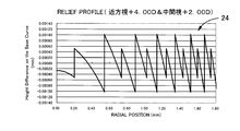
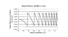
- the relief profile of the near vision relief that forms the relief shape.
- Relief profile of relief for intermediate vision that constitutes the relief shape.
- Relief profile with the same relief shape The relief profile which shows the relief shape as 2nd embodiment of this invention.
- the graph which shows the simulation result of the diffraction intensity in the relief shape The relief profile which shows the relief shape as 3rd embodiment of this invention.
- the graph which shows the simulation result of the diffraction intensity in the relief shape The relief profile which shows the relief shape as 4th embodiment of this invention.
- the graph which shows the simulation result of the diffraction intensity in the relief shape The cross-sectional model figure which shows the optical part of the intraocular lens as a different aspect of this invention.
- the cross-sectional model figure which shows the optical part of the intraocular lens as still another aspect of this invention.
- the graph which shows the simulation result of the diffraction intensity in the relief shape according to the conventional structure.
- the relief profile of the near vision relief which comprises the relief shape as the comparative example 2.
- FIG. The relief profile of the relief for intermediate vision which comprises the relief shape as the comparative example 2.
- FIG. The relief profile which shows the relief shape as the comparative example 2.
- FIG. The graph which shows the simulation result of the diffraction intensity in the relief shape.
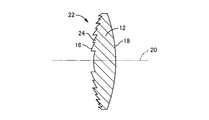
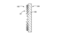
- FIG. 1 schematically shows a front view of an intraocular lens 10 as a first embodiment according to the aphakic intraocular lens of the present invention
- FIG. 2 describes the intraocular lens 10 later.
- a cross-sectional view of the optical unit 12 is shown as a model.
- the size of the relief 24 described later is exaggerated for easy understanding.
- the intraocular lens 10 includes an optical unit 12 that constitutes a lens body and gives the optical characteristics of the intraocular lens 10, and a pair of support units 14 that extend from the optical unit 12.
- the optical part 12 is formed with an optical part front surface 16 having a substantially spherical convex shape as a whole and an optical part rear surface 18 having a substantially spherical convex shape as a whole.
- the optical unit 12 as a whole has a substantially disc shape with a thick central portion, and the optical unit 12 has a rotating body shape with the lens central axis 20 as a geometric central axis as a rotation center axis. It is said that.
- the pair of support portions 14 are formed to extend in opposite directions from the two peripheral positions of the peripheral portion of the optical portion 12 that are opposed to each other in the radial direction.
- the free end is formed to be curved and extend in the circumferential direction of the optical unit 12.
- the optical unit 12 includes an optical unit front surface 16 and an optical unit rear surface 18 as lens surfaces, and the optical unit front surface 16 and the optical unit rear surface 18 are refracting surfaces.
- a predetermined focal length is set for the zero-order light from the optical unit front surface 16 and the optical unit rear surface 18.
- the optical part 12 As a forming material of the optical part 12, conventionally known resin materials made of various polymerizable monomers having optical properties such as light transmittance are preferably employed. Specifically, polymethyl methacrylate (PMMA) is used. ) And silicone rubber.
- PMMA polymethyl methacrylate
- silicone rubber silicone rubber
- the diffraction grating 22 is formed substantially over the entire front surface 16 of the optical unit in the present embodiment.
- the diffraction grating 22 is configured to include a relief 24 that is a undulating shape that extends concentrically around the lens central axis 20 and extends continuously in the lens circumferential direction.
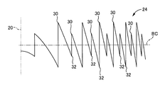
- FIG. 3 schematically shows the radial cross-sectional shape of the relief 24.
- the relief 24 in the present embodiment is formed by superimposing a near vision relief 26 whose radial cross-sectional shape is shown in FIG. 4 and an intermediate vision relief 28 whose radial cross-sectional shape is shown in FIG. ing. 3 to 5, in each of the reliefs 24, 26, and 28, when the base curve surface of the optical unit front surface 16 is a straight line: BC, the height dimension from the base curve surface in the lens radial direction is shown. It is a relief profile showing changes.
- Each of the near vision relief 26 and the intermediate vision relief 28 extends concentrically around the lens central axis 20 and projects toward the outside of the optical unit 12 (upward in FIGS. 3 to 5). And an undulating shape having a valley line 32 projecting inward (downward in FIGS. 3 to 5) of the optical unit 12.
- the lattice pitch refers to the radial width dimension between the ridge line 30 and the valley line 32.
- the zone is defined between the ridge line 30 and the valley line 32, and each zone is assigned a zone number of 1, 2, 3,...
- the zone radius is the outer peripheral radius of each zone, in other words, the concentric circles of the ridge line 30 or the valley line 32 positioned outside the center of the concentric circle (in this embodiment, the lens central axis 20) in each zone. The radius from the center.
- the lattice pitch is the radial width dimension of each zone
- the lattice pitch of a predetermined zone is the difference between the zone radius of the zone and the zone radius of a zone having a zone number smaller by 1 than the zone.
- the relief step means a separation distance in the optical axis direction between the ridge line 30 and the valley line 32 at the zone radius position.
- the ridge line 30 has a cross-sectional shape with an acute apex angle and extends in the circumferential direction of the optical unit 12
- the valley line 32 has a cross-sectional shape with an acute angle and the circumference of the optical unit 12.
- the shape extends in the direction.
- the near vision relief 26 and the intermediate vision relief 28 are respectively located in the ridge line 30 and the valley line 32 adjacent to each other in the lens radial direction, and the valley line 32 is positioned far from the lens center axis 20. Further, the near side protrudes from the front surface 16 of the optical unit as compared to the far side with respect to the lens center axis 20.
- the near vision relief 26 and the intermediate vision relief 28 are set so that the respective diffracted primary lights give different focal lengths.
- the near vision relief 26 has a refractive power of +4.00 D.
- the diffracted primary light by the near vision relief 26 is set as the focus for near vision
- the intermediate vision relief 28 is given a refractive power of +2.00 D
- the diffracted primary light by the intermediate vision relief 28 is given. Is set as the focus for intermediate vision.
- the focal length of the zero-order light by the optical unit front surface 16 and the optical unit rear surface 18 is different from the focal lengths of the diffracted primary light of the near vision relief 26 and the intermediate vision relief 28, and the optical unit front surface 16 and Zero-order light from the optical unit rear surface 18 is set as a far vision focus.
- the relief 24 is formed by superimposing the near vision relief 26 and the intermediate vision relief 28.
- the grid pitch of the intermediate vision relief 28 is set larger than the grid pitch of the near vision relief 26, and the grid of the zone of the near vision relief 26 with respect to the grid pitch of each zone of the intermediate vision relief 28.
- a synchronous structure in which pitches overlap periodically is set.
- the zone radius of each zone in the near vision relief 26 is periodically overlapped with the zone radius of each zone in the intermediate vision relief 28.
- one relief step of the near vision relief 26 is formed in one zone of the intermediate vision relief 28, and 2 of the near vision relief 26 is formed in one zone of the intermediate vision relief 28. Two zones are formed. That is, the zones of the intermediate vision relief 28 are overlapped at a ratio of two to the zones of the near vision relief 26.
- the near vision relief 26 and the intermediate vision relief 28 have the zone constant of the intermediate vision relief 28 as A, the zone constant of the near vision relief 26 as a, the zone number of the intermediate vision relief 28 as M, and the near vision relief.
- A (2 (m ⁇ NM) + a) / N Is set to satisfy.
- the zone constants A and a are constants for setting the zone radius of a predetermined zone number to a predetermined value.
- the near vision relief 26 and the intermediate vision relief 28 have a relief step height D, a design wavelength ⁇ , a lens material refractive index n lens , and an ambient medium refractive index n med , respectively.
- the relief step of the relief 24 is a combination of the relief steps of the reliefs 26 and 28 at the position where the near vision relief 26 and the intermediate vision relief 28 overlap.
- the size of each relief step of the intermediate vision relief 28 superimposed on the near vision relief 26 is constant in the zone direction (left and right direction in FIG. 3).
- the diffraction grating 22 is formed by forming the relief 28 formed by superimposing the near vision relief 26 and the intermediate vision relief 28 on the base curve surface of the front surface 16 of the optical unit.
- a far vision focus is given by the zero-order light of the optical unit front surface 16 and the optical unit rear surface 18, and near vision is obtained by the diffracted primary light of the near vision relief 26.
- the focal point for the intermediate vision can be provided by the diffracted primary light of the intermediate vision relief 28.
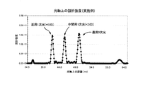
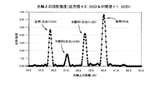
- FIG. 6 shows, as an example, a result of simulating on a computer the diffraction intensity on the optical axis obtained by the relief shape according to the present embodiment.
- the far-sighted focus by the zero-order light on the optical unit front surface 16 and the optical unit rear surface 18 as the refracting surface and the near-by-diffracted primary light of the near vision relief 26 are obtained. It can be confirmed that the peak of the intermediate focus due to the diffracted primary light of the intermediate vision relief 28 is generated between the normal focus. It can also be confirmed that the peak is clearly generated in any of these far vision, near vision, and intermediate vision.
- each diffracted primary light is generated in the entire relief 24.
- the relief 24 is formed by superimposing the near vision relief 26 and the intermediate vision relief 28
- each diffracted primary light is generated in the entire relief 24.
- the near vision relief 26 and the intermediate vision relief 28 are formed with a synchronous structure in which the lattice pitches of each other periodically overlap. Accordingly, it is possible to clearly obtain peaks due to the diffracted primary light of the near vision relief 26 and the intermediate vision relief 28, respectively, and it is possible to reduce the amount of stray light and reduce glare and the like.
- the shapes of the optical unit front surface 16 and the optical unit rear surface 18 on which the zero-order light generates a far vision focus are designed.
- the focal length of the zero-order light by the optical unit front surface 16 and the optical unit rear surface 18 is set to a focal length different from the focal length of the primary light of the near vision relief 26 and the intermediate vision relief 28.
- a conventionally known method can be appropriately employed.
- the central zone diameter is set to 0.2 mm, which is sufficiently smaller than the pupil diameter.
- Zone radius ⁇ ((2m + a) ⁇ f) (3)
- m is a zone number
- ⁇ a design wavelength
- a is a zone constant.
- the geometric parameters such as the curvature of the diffraction surface of the near vision relief 26, the shape parameters such as the center position, and the relief profile can be obtained.
- Table 1 shows the shape parameters of the near vision relief 26
- FIG. 8 shows the relief profile of the near vision relief 26.
- a relief shape of power + 2.00 D is designed as the relief for intermediate vision 28.
- the intermediate vision relief 28 needs to design primary light having a focal length different from that of the near vision relief 26 while being synchronized with the near vision relief 26 determined by the above procedure.
- Zone radius ⁇ ((2M + A) ⁇ (Nf)) (5) It is defined as M is a zone number, A is a zone constant, N is a ratio of the focal length of the intermediate vision relief and the focal length of the near vision relief, and is the focal length of the intermediate vision relief / the focal length of the near vision relief. .
- Zone radius ⁇ ((2M + 1.16) ⁇ (Nf)) (7) It is represented by
- the central relief height and the central vertex Y coordinate can be determined, and the diffraction of the intermediate vision relief 28 synchronized with the near vision relief 26 is geometrically related.
- Shape parameters such as the curvature of the surface and the center position and the relief profile can be obtained.
- Table 2 shows the shape parameters of the intermediate vision relief 28, and
- FIG. 9 shows the relief profile of the intermediate vision relief 28.
- the relief 24 is formed on the optical unit front surface 16.
- the relief 24 is formed on the front surface 16 of the optical part.
- not only mold forming but also machining such as laser processing, etching, cutting, and the like can be appropriately employed.
- the intraocular lens 10 as the above embodiment can be obtained.
- FIG. 11 shows a relief 50 as a relief profile as a second embodiment of the present invention.
- the near vision relief is formed of three zones with two relief steps for each zone of the intermediate vision relief, in other words, the zone radius of the near vision relief.
- the zone radius of the intermediate vision relief is matched with the zone radius of the near vision relief at a rate of one in three.
- the height relative to the virtual base curve surface at the relief step of the near vision relief positioned between the relief steps of the intermediate vision relief is the zone direction ( In the present embodiment, it gradually decreases as the distance from the center increases in the zone direction.
- a relief 50 can also be formed according to the same manufacturing method as in the first embodiment.
- FIG. 12 shows the result of simulating on the computer the diffraction intensity on the optical axis obtained by the relief 50 in the present embodiment, as in the first embodiment.
- the distance of the intermediate vision relief is between the distance vision focus by the zero-order light on the refracting surface and the near vision focus by the diffracted primary light of the near vision relief. It was confirmed that the peak of the focus for intermediate vision due to the diffracted primary light was generated, and a clear peak was generated in any of these far vision, near vision, and intermediate vision.
- the diffracted secondary light of the relief for intermediate vision is generated.
- a plurality of intermediate visions can be generated by changing the design parameters of the relief 50.
- the diffraction peak intensity and focus position can be set in various modes by, for example, adding a relief that overlaps periodically to the relief 50 having a synchronous structure.
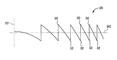
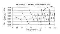
- FIG. 13 shows a relief 60 as a relief profile as a third embodiment of the present invention.
- the near vision relief is formed of three zones with two relief steps for each zone of the intermediate vision relief, in other words, the zone radius of the near vision relief.
- the zone radius of the intermediate vision relief is made to coincide with the zone radius of the near vision relief.
- the height relative to the virtual base curve surface at the relief step of the near vision relief positioned between the relief steps of the intermediate vision relief is the zone direction ( In FIG. 13, the horizontal direction is substantially constant.
- Such a relief 60 can be manufactured by a simpler method as compared with the first and second embodiments. That is, the relief having a synchronous structure can be simplified by increasing the relief step where the relief having the larger grating pitch overlaps the relief having the smaller grating pitch, based on the overlapping period of the plurality of reliefs that are superimposed on each other. Can be obtained.
- the power of the near vision relief and the intermediate vision relief in this embodiment is equal to that of the second embodiment, but as is clear from the second embodiment (see FIG. 11), the intermediate vision relief is near vision. Synchronize with the relief once every three times. Therefore, after designing the near vision relief shape according to the manufacturing method, the intermediate vision relief shape is not designed exactly as in the manufacturing method, but once for the obtained near vision relief shape.
- the relief shape close to the second embodiment can be easily obtained by increasing the relief step at the rate of rotation.
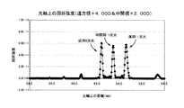
- FIG. 14 shows the result of simulating on the computer the diffraction intensity on the optical axis obtained by the relief 60 in the present embodiment, as in the first embodiment.
- the intermediate manufacturing method can be used with a simple manufacturing method. It was confirmed that the peak of the focus was produced and the effect similar to the second embodiment was obtained.
- FIG. 15 shows a relief 70 as a relief profile according to a fourth embodiment of the present invention.
- the relief 70 in the present embodiment is one in which the relief height of the relief 24 (see FIG. 10) in the first embodiment is reversed between the positive and negative sides. Is positioned closer to the center than the valley line 32.
- the 0th-order light on the refractive surface is set as the near vision focus, and the far-field relief diffraction-first order light is set as the distance vision focus, while the intermediate vision relief diffraction.
- ⁇ 1st order light is set as the focus for intermediate vision.
- the diffracted primary light in the present invention is understood as primary light as an absolute value including ⁇ 1st order light.
- FIG. 16 shows the result of simulating on the computer the diffraction intensity on the optical axis obtained by the relief 70 in the present embodiment, as in the first embodiment.
- the peak of the far vision focus due to the diffraction-first order light of the far vision relief occurs.
- a peak of the intermediate vision focus due to the diffraction-first-order light of the relief of intermediate vision occurs between the near vision focus and the far vision focus. Also in this embodiment, it has been confirmed that a clear peak is generated in any of these far vision, near vision, and intermediate vision.
- FIG. 17 shows a relief 80 as a relief profile according to a fifth embodiment of the present invention.
- the relief 80 in the present embodiment has a shape close to the relief 50 (see FIG. 11) as the second embodiment.
- the relief 80 is different from the relief 50 as the second embodiment.
- only the relief component of the near vision relief is gradually increased from 0 toward the outside from the center. In this way, the near-field diffraction intensity can be reduced.
- FIG. 18 shows the result of simulating on the computer the diffraction intensity on the optical axis obtained by the relief 80 in the present embodiment, as in the first embodiment.
- the peak of diffraction intensity at the near vision focus is reduced as compared with the second embodiment (see FIG. 12).
- the diffraction grating having a synchronous structure in which a plurality of reliefs are periodically overlapped is formed over substantially the entire optical unit front surface 16 in the optical unit 12. For example, it is formed only at the radial intermediate portion of the optical unit front surface 16, and only one type of relief is formed in other regions. May be.
- the relief 24 formed in the intraocular lens 10 as the first embodiment it is of course possible to form a diffraction grating having a synchronous structure on the optical unit rear surface 18.
- the lens surface on which the diffraction grating having a synchronous structure is formed is not limited to a refractive surface.
- a diffraction grating 22 is formed on one plane 102 having both surfaces 102 and 104 as shown in FIG. 19 as an optical part 100 of an intraocular lens as a different embodiment of the present invention.
- one surface is a flat surface 112 and the other surface is a refracting surface.
- the diffraction grating 22 may be formed on the flat surface 112 that is the curved surface 114.
- the diffraction grating according to the present invention may be formed on a laminated surface made of two materials having different dispersions as described in, for example, Japanese Patent Laid-Open No. 2001-42112. Is possible.
- Comparative Example 1 with respect to the example according to the first embodiment (see FIG. 6), the diffraction intensity obtained by the relief shape of the bifocal lens according to the conventional structure was simulated on a computer in the same manner as in the example.
- the relief shape of Comparative Example 1 a shape having a refractive power of +4.00 D for near vision was set. The simulation result is shown in FIG.
- the diffraction shape of the relief shape according to the example and the relief shape according to Comparative Example 1 is diffracted using wave optical design / analysis software (product name: Virtual Lab, manufactured by LightTrans). Intensity peak generation was verified.
- the verification results are shown in FIG. 22A for the example and FIG. 22B for the comparative example 1.
- the peak of the intermediate vision focus is strong between the distance vision focus and the near vision focus. was confirmed to occur.
- Comparative Example 2 an intraocular lens having a relief shape with an asynchronous structure in which the near vision relief and the intermediate vision relief were simply overlapped without being synchronized was prepared.
- Set the relief shape by overlapping the near vision relief and the intermediate vision relief with power + 2.00D with the zone constants set to 1 and not synchronizing with each other, and forming the relief shape on the front of the optical unit did.
- FIG. 23 shows a relief for near vision
- FIG. 24 shows a relief profile for relief for intermediate vision.
- FIG. 25 shows a relief profile as a comparative example 2 in which the near vision relief and the intermediate vision relief are overlapped without being synchronized with each other
- FIG. 26 is obtained by the relief shape of the comparative example 2.
- the simulation result of diffraction intensity is shown.
- FIG. 26 in Comparative Example 2 in which a plurality of relief shapes are simply superimposed, all of the zero-order light from the refractive surface, the diffracted primary light from the near vision relief, and the diffracted primary light from the intermediate vision relief are clear. It was confirmed that no significant peak was observed and that unintended order light was also generated.
- the usefulness of the present invention for setting a synchronous structure in which a plurality of reliefs periodically overlap each other has been clarified.
- 10 intraocular lens
- 12 optical unit
- 16 front surface of optical unit
- 20 lens central axis
- 22 diffraction grating
- 24 relief
- 26 near vision relief
- 28 intermediate vision relief
Landscapes
- Health & Medical Sciences (AREA)
- Ophthalmology & Optometry (AREA)
- Cardiology (AREA)
- Oral & Maxillofacial Surgery (AREA)
- Transplantation (AREA)
- Engineering & Computer Science (AREA)
- Biomedical Technology (AREA)
- Heart & Thoracic Surgery (AREA)
- Vascular Medicine (AREA)
- Life Sciences & Earth Sciences (AREA)
- Animal Behavior & Ethology (AREA)
- General Health & Medical Sciences (AREA)
- Public Health (AREA)
- Veterinary Medicine (AREA)
- Prostheses (AREA)
- Eyeglasses (AREA)
Abstract
Provided is a novel method for manufacturing an aphakic intraocular lens that can suppress influence due to a contraction of area or eccentricity and can obtain a focal effect more stable than any focusing effect of multiple focuses. At least two kinds of reliefs (26, 28) are arranged to overlap with each other, wherein the reliefs have diffracting primary light components that give mutually different focal points in at least a part of a region in the radial direction of an intraocular lens (10), respectively, and the reliefs are set to a synchronous structure in which a lattice pitch in those overlapping set reliefs against each lattice pitch of the maximum relief periodically overlaps with lattice pitches in the other relief, so that the obtained relief (24) is formed on a lens surface (16).
Description
本発明は、水晶体に代えて水晶体嚢内に配設される無水晶体眼内レンズに係り、特に、回折格子を有する無水晶体眼内レンズの製造方法、およびこれによって有利に製造される新規な構造の無水晶体眼内レンズに関するものである。
The present invention relates to an aphasic intraocular lens disposed in a capsular bag instead of a crystalline lens, and more particularly to a method of manufacturing an aphasic intraocular lens having a diffraction grating, and a novel structure advantageously manufactured thereby. The present invention relates to an aphakic intraocular lens.
良く知られているように、視力を司る水晶体は、遺伝や加齢等の要因によって、その調節能力が低下したり、水晶体自体の透明度等の特性が悪化することがあり、それに伴い、例えば近視、遠視、老視等の屈折異常や白内障等の問題が発生して、有効な視力が得られ難くなる。そして、そのような場合の処置のために、従来から、嚢内の水晶体を摘出、除去せしめた後、その水晶体に代替して嚢内に配設される、無水晶体眼内レンズ(以下、適宜に眼内レンズとする)が用いられている。
As is well known, the lens that controls visual acuity may have a reduced ability to adjust due to factors such as heredity and aging, and characteristics such as transparency of the lens itself may deteriorate. Problems such as refractive errors such as hyperopia and presbyopia and cataracts occur, making it difficult to obtain effective visual acuity. For treatment in such a case, conventionally, after removing and removing the crystalline lens in the sac, an aphakic intraocular lens (hereinafter referred to as an eye appropriately) disposed in the sac instead of the crystalline lens. Used as an inner lens).
ところが、従来から用いられている眼内レンズは単焦点のものであることから、術後の視力は回復するものの、焦点調節力の無い眼機能になってしまうという問題があった。
However, since the intraocular lens conventionally used has a single focal point, there is a problem that the postoperative visual acuity is restored, but the eye function has no focus adjustment ability.
このような問題に対処するために、例えば特許文献1等に記載の回折レンズ構造を適用して、光の回折作用を利用することによって複数の焦点を得ることの出来る眼内レンズが提案されている。特許文献1に記載の回折レンズは、レンズ表面にレリーフをもった回折格子を備え、レリーフを通過する光の回折現象を利用して、0次光と回折一次光によって、2つの焦点を形成することが可能とされている。従って、例えば0次光による焦点と回折一次光による焦点をそれぞれ遠方視用と近方視用に割り当てることによって、バイフォーカルな眼内レンズを得ることが出来る。
In order to cope with such a problem, an intraocular lens capable of obtaining a plurality of focal points by applying the diffractive lens structure described in, for example, Patent Document 1 and utilizing the diffractive action of light has been proposed. Yes. The diffractive lens described in Patent Document 1 includes a diffraction grating having a relief on the lens surface, and uses the diffraction phenomenon of light passing through the relief to form two focal points by zero-order light and diffracted primary light. It is possible. Therefore, a bifocal intraocular lens can be obtained, for example, by assigning the focus by the zero-order light and the focus by the diffracted primary light to far vision and near vision, respectively.
ところが、従来型の回折レンズ構造を適用したバイフォーカルな眼内レンズでは、視力回復には未だ不十分であることが、近年認識されつつある。即ち、例えば前記特許文献1に記載の回折レンズ構造を適用した眼内レンズでは、遠方視用と近方視用にそれぞれ0次光と一次光を割り当てているが、その結果、0次光と一次光の間へのエネルギーの配分が困難となって、中間視のコントラストが低くなるという問題が明らかとなってきたのである。
However, in recent years, it has been recognized that a bifocal intraocular lens to which a conventional diffractive lens structure is applied is still insufficient for restoring visual acuity. That is, for example, in the intraocular lens to which the diffractive lens structure described in Patent Document 1 is applied, the 0th order light and the primary light are assigned for far vision and near vision, respectively. The problem is that the distribution of energy between the primary lights becomes difficult and the contrast of intermediate vision becomes low.
そこで、より多数の焦点の生成を可能とするために、例えば特許文献2には、レンズ径方向にそれぞれ異なるレリーフを備えた複数の領域を形成することによって、複数の焦点を備えた眼内レンズが提案されている。しかし、特許文献2に記載の眼内レンズでは、縮瞳等によって入射光線径が変化するような場合には、目的とする焦点効果が発揮されなくなるおそれがあった。更にまた、仮に生理的な瞳孔径を考慮した設計であったとしても、瞳孔に対する所望の相対位置に眼内レンズを挿入し安定させることが出来るとは限らず、偏心等により目的とする焦点効果が発揮されなくなるおそれもあった。
Therefore, in order to enable generation of a larger number of focal points, for example, Patent Document 2 discloses an intraocular lens having a plurality of focal points by forming a plurality of regions each having a different relief in the lens radial direction. Has been proposed. However, in the intraocular lens described in Patent Document 2, when the incident light beam diameter changes due to miosis or the like, the target focus effect may not be exhibited. Furthermore, even if the design is based on a physiological pupil diameter, it is not always possible to insert and stabilize an intraocular lens at a desired relative position with respect to the pupil. There is also a risk that will not be exhibited.
ここにおいて、本発明は上述の如き事情を背景として為されたものであって、その解決課題とするところは、縮瞳や偏心による影響を抑え、多焦点の何れの焦点効果もより安定的に得ることの出来る無水晶体眼内レンズの、新規な製造方法を提供することにある。
Here, the present invention has been made in the background as described above, and the problem to be solved is to suppress the effects of miosis and eccentricity, and to make any multifocal focus effect more stable. It is an object of the present invention to provide a novel method for manufacturing an aphakic intraocular lens that can be obtained.
さらに、本発明は、そのような新規な製造方法によって有利に製造され得る、新規な構造の無水晶体眼内レンズを提供することをも、目的とする。
Furthermore, an object of the present invention is to provide an aphakic intraocular lens having a novel structure that can be advantageously produced by such a novel production method.
以下、前述の如き課題を解決するために為された本発明の態様を記載する。なお、以下に記載の各態様において採用される構成要素は、可能な限り任意の組み合わせで採用可能である。
Hereinafter, embodiments of the present invention made to solve the above-described problems will be described. In addition, the component employ | adopted in each aspect as described below is employable by arbitrary combinations as much as possible.
すなわち、無水晶体眼内レンズの製造方法に関する本発明の第一の態様は、レンズ表面に対して同心円状に延びるレリーフをもった回折格子を設けた水晶体嚢内に配設される無水晶体眼内レンズの製造方法であって、前記レリーフとして、それぞれの回折一次光が互いに異なる焦点距離を与える複数種類のレリーフを採用すると共に、レンズの径方向の少なくとも一部の領域において少なくとも二種類のレリーフを重ねて設定し、且つ、それらの重ねて設定したレリーフにおける格子ピッチが最大のレリーフの各格子ピッチに対して、他のレリーフにおける格子ピッチが周期的に重なり合う同期構造を設定して、得られたレリーフを前記レンズ表面に形成することを、特徴とする。
That is, the first aspect of the present invention relating to a method for manufacturing an aphakic intraocular lens is an aphasic intraocular lens disposed in a lens capsule provided with a diffraction grating having a relief extending concentrically with respect to the lens surface. In the manufacturing method, a plurality of types of reliefs that give different focal lengths to each diffracted primary light are employed as the relief, and at least two types of reliefs are overlapped in at least a partial region in the radial direction of the lens. And a relief structure obtained by setting a synchronous structure in which the grating pitches of the other reliefs are periodically overlapped for each grating pitch of the relief having the largest grating pitch in the relief set in an overlapping manner. Is formed on the lens surface.
本発明に従う製造方法によれば、少なくとも二種類のレリーフそれぞれの回折一次光によって、少なくとも2つの焦点を生成することが出来る。これにより、例えば眼内レンズの屈折面による0次光を遠方視用焦点に設定すると共に、二種類のレリーフの一方の一次光を近方視用焦点に設定するのに加えて、残り一方の一次光を中間視用焦点に設定することが可能となる。これにより、遠方視および近方視に加え、その中間の中間視においても良好な回折強度を得ることが出来て、中間視においてもより良好な視界を得ることの出来る眼内レンズを提供することが可能となる。なお、本発明におけるレリーフとは起伏形状をいう。
According to the manufacturing method according to the present invention, at least two focal points can be generated by the diffracted primary light of each of at least two types of reliefs. Thereby, for example, the zero-order light from the refractive surface of the intraocular lens is set as a far vision focus, and in addition to setting one primary light of two types of relief as a near vision focus, the remaining one It becomes possible to set the primary light as a focus for intermediate vision. Accordingly, it is possible to provide an intraocular lens capable of obtaining a good diffraction intensity in intermediate vision in addition to far vision and near vision, and obtaining a better field of view in intermediate vision. Is possible. In addition, the relief in this invention means the undulation shape.
そこにおいて、特に本製造方法によって製造された眼内レンズによれば、複数種類のレリーフが重ねて設定されている。これにより、複数種類のレリーフが重ね合わされた領域の全体でそれぞれのレリーフによる回折一次光が生成されることから、例えば前記特許文献2のように、領域毎に異なるレリーフを設定した回折レンズとは異なり、絞り等による入射光線径の変化やレンズの偏心等に対して、特定領域の回折強度が相対的に変化することも抑えることが出来て、所望の光学特性をより安定的に得ることの出来る、従来に無い新しい光学特性を備えた眼内レンズを得ることが出来る。
There, in particular, according to the intraocular lens manufactured by the present manufacturing method, a plurality of types of reliefs are set to overlap. Thereby, since the diffracted primary light by each relief is generated in the entire region where a plurality of types of reliefs are overlapped, for example, as in Patent Document 2, a diffraction lens in which different reliefs are set for each region. In contrast, it is possible to suppress the relative change in the diffraction intensity of a specific area with respect to a change in the diameter of the incident light beam due to a diaphragm or the like, or a decentration of the lens. It is possible to obtain an intraocular lens having a new optical characteristic which is not possible conventionally.
そして、特に本製造方法によれば、重ねて設定されたレリーフにおいて最大の格子ピッチを有するレリーフの各格子ピッチに対して、他のレリーフにおける格子ピッチが周期的に重なり合う同期構造が設定されており、換言すれば、最大の格子ピッチを有するレリーフの各ゾーン半径に対して、他のレリーフにおけるゾーン半径が周期的に重なり合う同期構造が設定されている。ここにおいて、格子ピッチとは、各レリーフの稜線と谷線の間の径方向幅寸法をいう。また、ゾーン半径とは、同心円状に延びる各レリーフの稜線と谷線の間のゾーンにおける、同心円の中心に対して外側に位置する稜線乃至は谷線の同心円の中心からの半径をいう。また、同心円状とは、光軸或いは偏倚軸を中心として円形やそれに近い楕円形などをもって環状に延びる複数条をいう。更にまた、本発明の請求項記載の「レンズの径方向」とは、光軸を中心とする径方向を言うものであり、レンズの幾何中心外に光軸を有する場合には、レンズ外周形状の径方向と必ずしも一致するものではない。これにより、それぞれのレリーフの回折一次光による回折強度のピークを何れも明確に生ぜしめることが出来て、多数の焦点をより確実に得ることが可能とされている。即ち、複数種類のレリーフを単に重ね合わせるのみでは、何れのレリーフによる回折強度のピークも明確に得ることが出来ず、意図しない次数光のピークの発生を引き起こすと共に、迷光等によるグレアの発生も大きくなる。これに対して、本製造方法によれば、異なる種類のレリーフの格子ピッチを同期させることによって、他のレリーフの回折一次光にも回折強度を有効に配分することが出来て、二次光等の必要の無い次数光の強度を低減することが可能となる。その結果、迷光等の光量を低減することが出来て、グレア等の低減も図られ得る。
In particular, according to this manufacturing method, for each lattice pitch of the relief having the maximum lattice pitch in the relief set in an overlapping manner, a synchronous structure in which the lattice pitch in the other relief is periodically overlapped is set. In other words, a synchronous structure in which the zone radii of other reliefs periodically overlap is set for each zone radius of the relief having the maximum lattice pitch. Here, the lattice pitch refers to the radial width dimension between the ridge line and valley line of each relief. Further, the zone radius means a radius from the center of the concentric circle of the ridge line or the valley line located outside the center of the concentric circle in the zone between the ridge line and the valley line of each relief extending concentrically. The concentric circle refers to a plurality of strips extending in a circular shape with a circular shape or an elliptical shape close to the optical axis or the deflection axis. Furthermore, “the radial direction of the lens” in the claims of the present invention refers to a radial direction centered on the optical axis, and when the optical axis is outside the geometric center of the lens, the outer peripheral shape of the lens It does not necessarily coincide with the radial direction. Thereby, it is possible to clearly generate any diffraction intensity peak due to the diffracted primary light of each relief, and to obtain a large number of focal points more reliably. That is, simply overlapping a plurality of types of relief does not provide a clear diffraction intensity peak due to any relief, causing an unintended order light peak, and causing a large amount of glare due to stray light or the like. Become. On the other hand, according to this manufacturing method, by synchronizing the grating pitches of different types of reliefs, diffraction intensity can be effectively distributed to the diffracted primary light of other reliefs, such as secondary light. It is possible to reduce the intensity of the order light that is not necessary. As a result, the amount of stray light and the like can be reduced, and glare and the like can be reduced.
なお、本発明における回折一次光とは、回折に伴う干渉光の一次のものであって、1波長分の位相差を生じる回折光である。即ち、光は、空気よりも高い屈折率の媒質内では速度が遅くなる。この作用を利用することで、同心円の中央側に稜線を有するレリーフの回折格子において、同心円の中央から周辺方向に向かって、隣り合うレリーフを通過する光が1波長ずつ遅れて重なることで得られる干渉光の一次のものが回折+1次光であり、反対に、同心円の外側に稜線を有する正負反転したレリーフの回折格子を用いた場合には、中央から周辺方向に向かって隣り合うレリーフを通過する光が1波長ずつ進んで重なることで得られる、レリーフ形状に関して反対側に発生する干渉光の一次のものが回折-1次光である。そして、本発明の請求項記載の「一次光」は、+1次光と-1次光の両者を含む絶対値としての一次光として理解されるものとする。
In addition, the diffracted primary light in the present invention is a diffracted light that is a primary one of interference light accompanying diffraction and generates a phase difference for one wavelength. That is, the speed of light is slower in a medium having a higher refractive index than air. By using this action, in a relief diffraction grating having a ridge line on the center side of the concentric circles, light passing through the adjacent reliefs overlaps with a delay of one wavelength from the center of the concentric circles toward the peripheral direction. The primary one of the interference light is diffraction + first order light, and conversely, if a relief grating with positive and negative inversions having a ridge line outside the concentric circle is used, it passes through adjacent reliefs from the center to the peripheral direction. The first order of the interference light generated on the opposite side with respect to the relief shape, which is obtained by overlapping the light to be transmitted one wavelength at a time, is diffracted-first order light. The “primary light” described in the claims of the present invention is understood as primary light as an absolute value including both + 1st order light and −1st order light.
また、本発明において、複数種類のレリーフは、レンズの径方向の少なくとも一部の領域において重ねて設定されていれば良いのであって、必ずしもレンズ全面に亘って複数種類のレリーフが重ねて設定される必要は無い。従って、例えば、レンズ中央部分のみやレンズ径方向中間部分のみ等において、複数種類のレリーフを重ねて設定し、他の領域では一種類のレリーフのみを設定する等しても良い。
In the present invention, the plurality of types of reliefs need only be set so as to overlap in at least a partial region in the radial direction of the lens, and the plurality of types of reliefs are not necessarily set over the entire surface of the lens. There is no need to Therefore, for example, a plurality of types of reliefs may be set to be overlapped only in the center portion of the lens or only in the middle portion in the lens radial direction, and only one type of relief may be set in other regions.
さらに、本発明における複数種類のレリーフとしては、少なくとも二種類であれば良いのであって、三種類以上のレリーフを重ねて設定することも、勿論可能である。
Furthermore, it is sufficient that there are at least two types of reliefs in the present invention, and it is of course possible to set three or more types of reliefs in an overlapping manner.
なお、本発明における無水晶体眼内レンズとは、水晶体を除去した後に、水晶体に代えて水晶体膿内に配設される眼内レンズを言う。そして、レリーフの同期構造が形成される基準面の形状や材質等は特に限定されるものではない。例えば、かかる基準面は凸および凹を含む球面の他、非球面、シリンドリカル面、トーリック面などであっても良く、或いは平面であっても良い。特に、基準面が平面以外の場合には、光学的な屈折特性も、本発明の回折に加えて発揮されることとなる。
The aphakic intraocular lens in the present invention refers to an intraocular lens disposed in the lens pus instead of the lens after removing the lens. The shape and material of the reference surface on which the relief synchronous structure is formed are not particularly limited. For example, such a reference surface may be an aspherical surface, a cylindrical surface, a toric surface, or the like, in addition to a spherical surface including convex and concave portions, or a flat surface. In particular, when the reference surface is other than a flat surface, the optical refraction characteristics are also exhibited in addition to the diffraction of the present invention.
無水晶体眼内レンズの製造方法に関する本発明の第二の態様は、前記第一の態様に係る眼内レンズの製造方法において、前記レンズの屈折面による0次光に対して、前記複数種類のレリーフによる何れの回折一次光の焦点距離とも異なる焦点距離を設定することを、特徴とする。
A second aspect of the present invention relating to a method for manufacturing an aphakic intraocular lens is the method for manufacturing an intraocular lens according to the first aspect. It is characterized in that a focal length different from the focal length of any diffracted primary light by the relief is set.
本態様によれば、少なくとも二種類のレリーフそれぞれの回折一次光による焦点と、屈折面による0次光の焦点によって、3つ以上の焦点を有する眼内レンズを得ることが出来る。ここにおいて、複数のレリーフは、屈折面に形成されていても良いし、屈折面以外の面に形成されていても良い。従って、本態様は、一方が凹面や凸面の屈折面としての湾曲面で、他方が非屈折面としての平面とされた眼内レンズに対して、その平面側にレリーフを形成する態様も含むものであるし、無水晶体眼内レンズの製造方法に関する本発明の第三の態様として、前記第二の態様に係る眼内レンズの製造方法において、前記レリーフを形成する前記レンズ表面が、前記屈折面である態様も含むものである。
According to this aspect, an intraocular lens having three or more focal points can be obtained by the focal point of the diffracted primary light of each of at least two types of reliefs and the focal point of the zero-order light by the refractive surface. Here, the plurality of reliefs may be formed on the refracting surface, or may be formed on a surface other than the refracting surface. Therefore, this aspect also includes an aspect in which a relief is formed on the plane side of an intraocular lens in which one is a curved surface as a concave surface or a convex refractive surface and the other is a flat surface as a non-refractive surface. As a third aspect of the present invention relating to a method for manufacturing an aphakic intraocular lens, in the method for manufacturing an intraocular lens according to the second aspect, the lens surface forming the relief is the refractive surface. Embodiments are also included.
無水晶体眼内レンズの製造方法に関する本発明の第四の態様は、前記第一乃至第三の何れか一つの態様に係る眼内レンズの製造方法において、前記格子ピッチが最大のレリーフのレリーフ段差であって、前記複数のレリーフが重なった各レリーフ段差の大きさが、ゾーン方向で一定となるように形成することを、特徴とする。
According to a fourth aspect of the present invention relating to a method for manufacturing an aphakic intraocular lens, in the method for manufacturing an intraocular lens according to any one of the first to third aspects, the relief step of the relief having the maximum lattice pitch. In this case, it is characterized in that the size of each relief step where the plurality of reliefs overlap is made constant in the zone direction.
ここにおいて、レリーフ段差とは、レリーフの各ゾーン半径位置における光軸方向寸法をいう。本態様によれば、格子ピッチが最大のレリーフのレリーフ段差をゾーン毎に設定することが不要とされて、レリーフ形状をより容易に設定することが出来る。
Here, the relief step means a dimension in the optical axis direction at each zone radius position of the relief. According to this aspect, it is not necessary to set the relief step of the relief having the maximum lattice pitch for each zone, and the relief shape can be set more easily.
無水晶体眼内レンズの製造方法に関する本発明の第五の態様は、前記第四の態様に係る眼内レンズの製造方法において、前記複数のレリーフを重ねて設定した径方向の領域には、前記格子ピッチが最大のレリーフの各一つのゾーンにおいて、別の種類の前記レリーフが少なくとも二つのレリーフ段差をもって形成され、且つそれら少なくとも二つのレリーフ段差における前記ベース表面に対する高さがゾーン方向で次第に変化するように設定することを、特徴とする。
According to a fifth aspect of the present invention relating to a method for manufacturing an aphakic intraocular lens, in the method for manufacturing an intraocular lens according to the fourth aspect, the radial region in which the plurality of reliefs are set to overlap each other includes In each zone of the relief with the largest lattice pitch, another type of relief is formed with at least two relief steps, and the height of the at least two relief steps relative to the base surface gradually changes in the zone direction. It is characterized by setting as follows.
本態様によれば、別の種類のレリーフのレリーフ段差をより精度良く設定することが出来て、別の種類のレリーフによる回折強度のピークをより明瞭に生ぜしめることが出来る。なお、本態様において、レリーフ段差におけるベース表面に対する高さがゾーン方向で次第に変化するとは、ゾーン方向で次第に低くなる態様と、高くなる態様の何れをも含む。
According to this aspect, the relief step of another type of relief can be set with higher accuracy, and the peak of diffraction intensity due to another type of relief can be generated more clearly. In addition, in this aspect, that the height with respect to the base surface in a relief level | step difference changes gradually in a zone direction includes both the aspect which becomes low gradually in a zone direction, and the aspect which becomes high.
無水晶体眼内レンズの製造方法に関する本発明の第六の態様は、前記第四の態様に係る眼内レンズの製造方法において、前記複数のレリーフを重ねて設定した径方向の領域には、前記格子ピッチが最大のレリーフの各一つのゾーンにおいて、別の種類の前記レリーフが少なくとも二つのレリーフ段差をもって形成され、且つそれら少なくとも二つのレリーフ段差における前記ベース表面に対する高さがゾーン方向で一定となるように設定することを、特徴とする。本態様によれば、別の種類のレリーフの形状をゾーン半径ごとに設定することが不要とされて、別の種類のレリーフ形状をより容易に設定することが出来る。
According to a sixth aspect of the present invention relating to a method for manufacturing an aphakic intraocular lens, in the intraocular lens manufacturing method according to the fourth aspect, the radial region in which the plurality of reliefs are set to overlap each other is In each one zone of the relief having the largest lattice pitch, another type of the relief is formed with at least two relief steps, and the height of the at least two relief steps with respect to the base surface is constant in the zone direction. It is characterized by setting as follows. According to this aspect, it is unnecessary to set another type of relief shape for each zone radius, and another type of relief shape can be set more easily.
無水晶体眼内レンズの製造方法に関する本発明の第七の態様は、前記第一乃至第六の何れか一つの態様に係る眼内レンズの製造方法において、複数種類の前記レリーフが、何れも、鋭角の頂角をもった断面形状で周方向に延びる稜線と鋭角の夾角をもった断面形状で周方向に延びる谷線とを有していることを、特徴とする。
A seventh aspect of the present invention relating to a method for manufacturing an aphakic intraocular lens is the method for manufacturing an intraocular lens according to any one of the first to sixth aspects. It has a ridge line extending in the circumferential direction with a cross-sectional shape having an acute apex angle and a trough line extending in the circumferential direction with a cross-sectional shape having an acute depression angle.
本態様によれば、複数種類のレリーフにおいて回折作用をそれぞれ有効に生ぜしめることが出来て、各種類のレリーフの回折一次光のピークをそれぞれ有効に生ぜしめることが出来る。
According to this aspect, it is possible to effectively generate diffraction effects in a plurality of types of reliefs, and it is possible to effectively generate peaks of diffraction primary light of each type of reliefs.
無水晶体眼内レンズの製造方法に関する本発明の第八の態様は、前記第一乃至第七の何れか一つの態様に係る眼内レンズの製造方法において、前記レンズの屈折面による0次光を遠方視用焦点に設定する一方、一つの種類の前記レリーフによる回折一次光を近方視用焦点に設定すると共に、別の種類の前記レリーフによる回折一次光を中間視用焦点に設定することを、特徴とする。
According to an eighth aspect of the present invention relating to a method for manufacturing an aphakic intraocular lens, in the method for manufacturing an intraocular lens according to any one of the first to seventh aspects, zero-order light from the refractive surface of the lens is obtained. While setting the focus for distance vision, setting the primary light diffracted by one type of relief as the focus for near vision and setting the primary light diffracted by another type of relief as the focus for intermediate vision. , Feature.
本態様によれば、遠方視用焦点および近方視用焦点に加えて、中間視用焦点を備えた眼内レンズを得ることが出来る。従って、回折型の眼内レンズにおいてこれまで問題とされていた、中間視のコントラスト低下の問題も改善され得て、より良好な中間視を得ることが出来る。
According to this aspect, it is possible to obtain an intraocular lens having an intermediate vision focus in addition to the far vision focus and the near vision focus. Therefore, the problem of lowering the contrast of intermediate vision, which has been a problem with diffractive intraocular lenses, can be improved, and better intermediate vision can be obtained.
無水晶体眼内レンズの製造方法に関する本発明の第九の態様は、前記第一乃至第七の何れか一つの態様に係る眼内レンズの製造方法において、前記レンズの屈折面による0次光を近方視用焦点に設定する一方、一つの種類の前記レリーフによる回折一次光を遠方視用焦点に設定すると共に、別の種類の前記レリーフによる回折一次光を中間視用焦点に設定することを、特徴とする。
According to a ninth aspect of the present invention relating to a method for manufacturing an aphakic intraocular lens, in the method for manufacturing an intraocular lens according to any one of the first to seventh aspects, zero-order light from the refractive surface of the lens is obtained. While setting the focal point for near vision, setting the primary light diffracted by one type of relief as the focal point for far vision and setting the primary light diffracted by another type of relief as the focal point for intermediate vision. , Feature.
本態様においても、より良好な中間視を実現することの出来る眼内レンズを得ることが出来る。なお、本態様においては、近方視用焦点および遠方視用焦点が何れも、対応するレリーフの-1次光となるが、前述のように、本発明における一次光は、-1次光を含む絶対値としての一次光として理解される。
Also in this embodiment, an intraocular lens capable of realizing better intermediate vision can be obtained. In this aspect, the near vision focus and the far vision focus are both the corresponding relief -1st order light. However, as described above, the primary light in the present invention is the -1st order light. It is understood as primary light as an absolute value including.
無水晶体眼内レンズの製造方法に関する本発明の第十の態様は、前記第一乃至第九の何れか一つの態様に係る眼内レンズの製造方法において、複数の前記レリーフは、一方の該レリーフのゾーン定数をA、他方の該レリーフのゾーン定数をa,一方の該レリーフのゾーン番号をM、他方の該レリーフのゾーン番号をm、一方の該レリーフの焦点距離/他方の該レリーフの焦点距離をNとして、下式:
A=(2(m-NM)+a)/N
を満足するように設定されていることを、特徴とする。 A tenth aspect of the present invention relating to a method for manufacturing an aphakic intraocular lens is the method for manufacturing an intraocular lens according to any one of the first to ninth aspects, wherein a plurality of the reliefs are one of the reliefs. The zone constant of A is the zone constant of the other relief, the zone number of one relief is M, the zone number of the other relief is m, the focal length of one relief / the focus of the other relief. Let N be the distance:
A = (2 (m−NM) + a) / N
It is set so that it may satisfy | fill.
ここにおいて、ゾーン定数とは、所定ゾーン番号のゾーン半径を所定の値に設定するための定数であり、ゾーン半径は、ゾーン定数:aを用いて、下式:
ゾーン半径=√((2m+a)λf)
で表される。なお、λは設計波長、fは焦点距離を示す。また、ゾーン番号とは、ゾーン毎に割り振られた番号であり、中央を0としてゾーン方向外方に向けて1、2、3、…の順に割り振られる番号である。 Here, the zone constant is a constant for setting the zone radius of the predetermined zone number to a predetermined value, and the zone radius is expressed by the following formula:
Zone radius = √ ((2m + a) λf)
It is represented by Note that λ is a design wavelength, and f is a focal length. Further, the zone number is a number assigned to each zone, and is a number assigned in the order of 1, 2, 3,...
本態様によれば、他方のレリーフの格子ピッチに対して、一方のレリーフの格子ピッチが周期的に重なり合う同期構造を容易に設定することが出来る。
According to this aspect, a synchronous structure in which the grating pitch of one relief periodically overlaps with the grating pitch of the other relief can be easily set.
無水晶体眼内レンズの製造方法に関する本発明の第十一の態様は、前記第一乃至第十の何れか一つの態様に係る眼内レンズの製造方法において、複数の前記レリーフは、レリーフ段差の高さ寸法をD、設計波長をλ、前記光学材料の屈折率をNlens、周囲媒質屈折率をNmed として、下式:
D≦λ/(Nlens-Nmed )
を満足するように設定されていることを、特徴とする。 An eleventh aspect of the present invention relating to a method for manufacturing an aphakic intraocular lens is the method for manufacturing an intraocular lens according to any one of the first to tenth aspects, wherein the plurality of reliefs are relief steps. Assuming that the height dimension is D, the design wavelength is λ, the refractive index of the optical material is N lens and the refractive index of the surrounding medium is N med , the following formula:
D ≦ λ / (N lens -N med )
It is set so that it may satisfy | fill.
本態様によれば、レリーフ段差は最大1波長分に相当し、0次光と1次光との光の配分をより有効に確保することが出来る。従って、本態様は、前記第三の態様のように、レリーフ形状が屈折面に形成された態様と組み合わせて、好適に用いられる。このようにすれば、二次光等の必要のない次数光の強度を低減でき、0次光と1次光の焦点効果をより有効に確保することが出来る。
According to this aspect, the relief step corresponds to a maximum of one wavelength, and the light distribution between the 0th order light and the 1st order light can be more effectively ensured. Therefore, this aspect is suitably used in combination with the aspect in which the relief shape is formed on the refracting surface as in the third aspect. In this way, the intensity of the unnecessary order light such as the secondary light can be reduced, and the focus effect of the 0th order light and the primary light can be more effectively ensured.
無水晶体眼内レンズに関する本発明の第一の態様は、レンズ表面に対して同心円状に延びるレリーフをもった回折格子が設けられた水晶体嚢内に配設される無水晶体眼内レンズであって、レンズの径方向の少なくとも一部の領域において、それぞれの回折一次光が互いに異なる焦点距離を与える少なくとも二種類のレリーフが重ねて設定されており、且つ、それらの重ねて設定されたレリーフにおける格子ピッチが最大のレリーフの各格子ピッチに対して、他のレリーフにおける格子ピッチが周期的に重なり合う周期構造を有することを、特徴とする。
A first aspect of the present invention relating to an aphakic intraocular lens is an aphasic intraocular lens disposed in a capsular bag provided with a diffraction grating having a relief extending concentrically with respect to the lens surface, In at least a partial region in the radial direction of the lens, at least two types of relief in which each diffracted primary light gives different focal lengths are set to be overlapped, and the grating pitch in the overlapped relief is set. Is characterized by having a periodic structure in which the grating pitches of other reliefs periodically overlap with each grating pitch of the largest relief.
本態様における眼内レンズによれば、少なくとも二種類のレリーフそれぞれの回折一次光によって、少なくとも2つの焦点を生成することが出来る。これにより、例えば眼内レンズの屈折面による0次光によって遠方視用焦点を得ると共に、二種類のレリーフの一方の一次光によって近方視用焦点を得るのに加えて、残り一方の一次光によって中間視用焦点を得ることが可能となる。これにより、遠方視および近方視に加え、その中間の中間視においても良好な回折強度を得ることが出来て、中間視においてもより良好な視界を得ることの出来る無水晶体眼内レンズを提供することが可能となる。なお、本発明におけるレリーフとは起伏形状をいう。
According to the intraocular lens in this aspect, at least two focal points can be generated by the diffracted primary light of each of at least two types of relief. Thus, for example, the far-sighted focus is obtained by the zero-order light from the refractive surface of the intraocular lens, and the near-focused focus is obtained by the primary light of one of the two types of reliefs, and the remaining primary light is obtained. This makes it possible to obtain a focus for intermediate vision. This provides an aphakic intraocular lens that can obtain good diffraction intensity even in intermediate vision in addition to distance vision and near vision, and in which better vision can be obtained even in intermediate vision. It becomes possible to do. In addition, the relief in this invention means the undulation shape.
そこにおいて、特に本態様における眼内レンズによれば、複数種類のレリーフが重ねて設定されている。これにより、複数種類のレリーフが重ね合わされた領域の全体でそれぞれのレリーフによる回折一次光が生成されることから、例えば前記特許文献2のように、領域毎に異なるレリーフを設定した回折レンズとは異なり、絞り等による入射光線径の変化やレンズの偏心等に対して、特定領域の回折強度が相対的に変化することも抑えることが出来て、所望の光学特性をより安定的に得ることの出来る、従来に無い新しい光学特性を備えた眼内レンズを得ることが出来る。
Therefore, in particular, according to the intraocular lens in this embodiment, a plurality of types of reliefs are set to overlap. Thereby, since the diffracted primary light by each relief is generated in the entire region where a plurality of types of reliefs are overlapped, for example, as in Patent Document 2, a diffraction lens in which different reliefs are set for each region. In contrast, it is possible to suppress the relative change in the diffraction intensity of a specific area with respect to a change in the diameter of the incident light beam due to a diaphragm or the like, or a decentration of the lens, and the desired optical characteristics can be obtained more stably. It is possible to obtain an intraocular lens having a new optical characteristic which is not possible conventionally.
そして、特に本態様においては、重ねて設定されたレリーフにおいて最大の格子ピッチを有するレリーフの各格子ピッチに対して、他のレリーフにおける格子ピッチが周期的に重なり合う同期構造を備えており、換言すれば、最大の格子ピッチを有するレリーフの各ゾーン半径に対して、他のレリーフにおけるゾーン半径が周期的に重なり合う同期構造を有している。なお、同心円状とは、光軸或いは偏倚軸を中心として円形やそれに近い楕円形などをもって環状に延びる複数条をいう。そして、本発明の請求項記載の「レンズの径方向」とは、光軸を中心とする径方向を言うものであり、レンズの幾何中心外に光軸を有する場合には、レンズ外周形状の径方向と必ずしも一致するものではない。これにより、それぞれのレリーフの回折一次光による回折強度のピークを何れも明確に生ぜしめることが出来て、多数の焦点をより確実に得ることが可能とされている。即ち、複数種類のレリーフを単に重ね合わせるのみでは、何れのレリーフによる回折強度のピークも明確に得ることが出来ず、意図しない次数光のピークの発生を引き起こすと共に、迷光等によるグレアの発生も大きくなる。これに対して、本態様における眼内レンズによれば、異なる種類のレリーフの格子ピッチが同期されていることによって、他のレリーフの回折一次光にも回折強度を有効に配分することが出来て、二次光等の必要の無い次数光の強度を低減することが可能となる。その結果、迷光等の光量を低減することが出来て、グレア等の低減も図られ得る。
In particular, the present embodiment includes a synchronous structure in which the grating pitches of the other reliefs periodically overlap each grating pitch of the relief having the largest grating pitch in the relief set in an overlapping manner, in other words, For example, each zone radius of the relief having the maximum grating pitch has a synchronous structure in which the zone radii of other reliefs periodically overlap. The concentric circle means a plurality of strips extending in an annular shape with a circular shape or an elliptical shape close to the optical axis or the deflection axis. The “lens radial direction” in the claims of the present invention refers to a radial direction centered on the optical axis, and when the optical axis is outside the geometric center of the lens, It does not necessarily coincide with the radial direction. Thereby, it is possible to clearly generate any diffraction intensity peak due to the diffracted primary light of each relief, and to obtain a large number of focal points more reliably. That is, simply overlapping a plurality of types of relief does not provide a clear diffraction intensity peak due to any relief, causing an unintended order light peak, and causing a large amount of glare due to stray light or the like. Become. On the other hand, according to the intraocular lens in this aspect, the diffraction pitch can be effectively distributed to the diffracted primary light of other reliefs by synchronizing the grating pitches of different types of reliefs. It is possible to reduce the intensity of the order light that does not require secondary light or the like. As a result, the amount of stray light and the like can be reduced, and glare and the like can be reduced.
また、本態様において、複数種類のレリーフは、レンズの径方向の少なくとも一部の領域において重ねて設定されていれば良いのであって、必ずしもレンズ全面に亘って複数種類のレリーフが重ねて設定されている必要は無い。従って、例えば、レンズ中央部分のみやレンズ径方向中間部分のみ等において、複数種類のレリーフが重ねて設定されており、他の領域では一種類のレリーフのみが設定される等しても良い。
Further, in this aspect, the plurality of types of reliefs may be set so as to overlap in at least a partial region in the radial direction of the lens, and the plurality of types of reliefs are not necessarily set over the entire surface of the lens. There is no need to Therefore, for example, a plurality of types of reliefs may be set to be overlapped only in the center portion of the lens or only in the middle portion in the lens radial direction, and only one type of relief may be set in other regions.
さらに、本態様における複数種類のレリーフとしては、少なくとも二種類であれば良いのであって、三種類以上のレリーフを重ねて設定することも、勿論可能である。
Furthermore, it is sufficient that there are at least two types of reliefs in the present embodiment, and it is of course possible to set three or more types of reliefs in an overlapping manner.
なお、本態様における無水晶体眼内レンズとは、水晶体を除去した後に、水晶体に代えて水晶体膿内に配設される眼内レンズを言う。そして、レリーフの同期構造が形成される基準面の形状や材質等は特に限定されるものではない。例えば、かかる基準面は凸および凹を含む球面の他、非球面、シリンドリカル面、トーリック面などであっても良く、或いは平面であっても良い。特に、基準面が平面以外の場合には、光学的な屈折特性も、本態様の回折に加えて発揮されることとなる。
It should be noted that the aphakic intraocular lens in this embodiment refers to an intraocular lens disposed in the lens pus instead of the lens after removing the lens. The shape and material of the reference surface on which the relief synchronous structure is formed are not particularly limited. For example, such a reference surface may be an aspherical surface, a cylindrical surface, a toric surface, or the like, in addition to a spherical surface including convex and concave portions, or a flat surface. In particular, when the reference surface is other than a flat surface, the optical refraction characteristics are also exhibited in addition to the diffraction of this embodiment.
無水晶体眼内レンズに関する本発明の第二の態様は、前記第一の態様に係る無水晶体眼内レンズにおいて、前記レンズの屈折面による0次光に対して、前記複数種類のレリーフによる何れの回折一次光の焦点距離とも異なる焦点距離が設定されていることを、特徴とする。
According to a second aspect of the present invention relating to the aphakic intraocular lens, in the aphasic intraocular lens according to the first aspect, any one of the reliefs of the plurality of types with respect to the zero-order light from the refractive surface of the lens. A focal length different from the focal length of the diffracted primary light is set.
本態様によれば、少なくとも二種類のレリーフそれぞれの回折一次光による焦点と、屈折面による0次光の焦点によって、3つ以上の焦点を有する眼内レンズを得ることが出来る。ここにおいて、複数のレリーフは、屈折面に形成されていても良いし、屈折面以外の面に形成されていても良い。従って、本態様は、一方が凹面や凸面の屈折面としての湾曲面で、他方が非屈折面としての平面とされた眼内レンズに対して、その平面側にレリーフが形成された態様も含むものであるし、無水晶体眼内レンズに関する本発明の第三の態様として、前記第二の態様に係る眼内レンズにおいて、前記レリーフが形成される前記レンズ表面が、前記屈折面である態様も含むものである。
According to this aspect, an intraocular lens having three or more focal points can be obtained by the focal point of the diffracted primary light of each of at least two types of reliefs and the focal point of the zero-order light by the refractive surface. Here, the plurality of reliefs may be formed on the refracting surface, or may be formed on a surface other than the refracting surface. Therefore, this mode also includes a mode in which a relief is formed on the plane side of an intraocular lens in which one is a curved surface as a concave or convex refractive surface and the other is a flat surface as a non-refractive surface. As a third aspect of the present invention relating to an aphakic intraocular lens, the intraocular lens according to the second aspect includes an aspect in which the lens surface on which the relief is formed is the refractive surface. .
無水晶体眼内レンズに関する本発明の第四の態様は、前記第一乃至第三の何れか一つの態様に係る眼内レンズにおいて、前記格子ピッチが最大のレリーフのレリーフ段差であって、前記複数のレリーフが重なった各レリーフ段差の大きさが、ゾーン方向で一定とされていることを、特徴とする。
According to a fourth aspect of the present invention relating to the aphakic intraocular lens, the intraocular lens according to any one of the first to third aspects is a relief step of a relief having the largest lattice pitch, The size of each relief step where the reliefs overlap is made constant in the zone direction.
ここにおいて、レリーフ段差とは、レリーフの各ゾーン半径位置における光軸方向寸法をいう。本態様によれば、格子ピッチが最大のレリーフのレリーフ段差をゾーン毎に設定することが不要とされて、レリーフ形状をより容易に設定することが可能となり、製造もより容易となる。
Here, the relief step means a dimension in the optical axis direction at each zone radius position of the relief. According to this aspect, it is not necessary to set the relief level difference of the relief having the maximum lattice pitch for each zone, the relief shape can be set more easily, and the manufacturing becomes easier.
無水晶体眼内レンズに関する本発明の第五の態様は、前記第四の態様に係る眼内レンズにおいて、前記複数のレリーフを重ねて設定した径方向の領域には、前記格子ピッチが最大のレリーフの各一つのゾーンにおいて、別の種類の前記レリーフが少なくとも二つのレリーフ段差をもって形成され、且つそれら少なくとも二つのレリーフ段差における前記ベース表面に対する高さがゾーン方向で次第に変化していることを、特徴とする。
According to a fifth aspect of the present invention relating to an aphakic intraocular lens, in the intraocular lens according to the fourth aspect, a relief having the largest lattice pitch is provided in a radial region set by overlapping the plurality of reliefs. In each of the zones, another type of the relief is formed with at least two relief steps, and the height of the at least two relief steps with respect to the base surface gradually changes in the zone direction. And
本態様によれば、別の種類のレリーフのレリーフ段差がより精度良く設定されて、別の種類のレリーフによる回折強度のピークをより明瞭に生ぜしめることが出来る。なお、本態様において、レリーフ段差におけるベース表面に対する高さがゾーン方向で次第に変化するとは、ゾーン方向で次第に低くなる態様と、高くなる態様の何れをも含む。
According to this aspect, the relief step of another type of relief is set with higher accuracy, and the peak of diffraction intensity due to another type of relief can be generated more clearly. In addition, in this aspect, that the height with respect to the base surface in a relief level | step difference changes gradually in a zone direction includes both the aspect which becomes low gradually in a zone direction, and the aspect which becomes high.
無水晶体眼内レンズに関する本発明の第六の態様は、前記第四の態様に係る眼内レンズにおいて、前記複数のレリーフを重ねて設定した径方向の領域には、前記格子ピッチが最大のレリーフの各一つのゾーンにおいて、別の種類の前記レリーフが少なくとも二つのレリーフ段差をもって形成され、且つそれら少なくとも二つのレリーフ段差における前記ベース表面に対する高さがゾーン方向で一定とされていることを、特徴とする。本態様によれば、別の種類のレリーフの形状をゾーン半径ごとに設定することが不要とされて、別の種類のレリーフ形状をより容易に形成することが出来る。
According to a sixth aspect of the present invention relating to the aphakic intraocular lens, in the intraocular lens according to the fourth aspect, a relief in which the lattice pitch is maximum is provided in a radial region in which the plurality of reliefs are overlapped. In each of the zones, another type of the relief is formed with at least two relief steps, and the height of the at least two relief steps with respect to the base surface is constant in the zone direction. And According to this aspect, it is unnecessary to set the shape of another type of relief for each zone radius, and another type of relief shape can be more easily formed.
無水晶体眼内レンズに関する本発明の第七の態様は、前記第一乃至第六の何れか一つの態様に係る眼内レンズにおいて、複数種類の前記レリーフが、何れも、鋭角の頂角をもった断面形状で周方向に延びる稜線と鋭角の夾角をもった断面形状で周方向に延びる谷線とを有していることを、特徴とする。
A seventh aspect of the present invention relating to an aphakic intraocular lens is the intraocular lens according to any one of the first to sixth aspects, wherein the plurality of types of relief each have an acute apex angle. It has a ridge line extending in the circumferential direction with a cross-sectional shape and a valley line extending in the circumferential direction with a cross-sectional shape having an acute depression angle.
本態様によれば、複数種類のレリーフにおいて回折作用をそれぞれ有効に生ぜしめることが出来て、各種類のレリーフの回折一次光のピークをそれぞれ有効に生ぜしめることが出来る。
According to this aspect, it is possible to effectively generate diffraction effects in a plurality of types of reliefs, and it is possible to effectively generate peaks of diffraction primary light of each type of reliefs.
無水晶体眼内レンズに関する本発明の第八の態様は、前記第一乃至第七の何れか一つの態様に係る眼内レンズにおいて、前記レンズの屈折面による0次光が遠方視用焦点に設定されている一方、一つの種類の前記レリーフによる回折一次光が近方視用焦点に設定されていると共に、別の種類の前記レリーフによる回折一次光が中間視用焦点に設定されていることを、特徴とする。
An eighth aspect of the present invention relating to an aphakic intraocular lens is the intraocular lens according to any one of the first to seventh aspects, wherein the zero-order light from the refractive surface of the lens is set as a focal point for far vision. On the other hand, diffracted primary light from one type of relief is set as a near vision focus, and diffracted primary light from another type of relief is set as an intermediate focus. , Feature.
本態様によれば、遠方視用焦点および近方視用焦点に加えて、中間視用焦点を得ることが出来る。従って、これまで回折型の眼内レンズにおいて問題とされていた、中間視のコントラスト低下の問題も改善され得て、より良好な中間視を得ることが出来る。
According to this aspect, in addition to the far vision focus and the near vision focus, the intermediate vision focus can be obtained. Therefore, the problem of lowering the contrast of intermediate vision, which has been a problem with diffractive intraocular lenses, can be improved and better intermediate vision can be obtained.
無水晶体眼内レンズに関する本発明の第九の態様は、前記第一乃至第七の何れか一つの態様に係る眼内レンズにおいて、前記レンズの屈折面による0次光が近方視用焦点に設定されている一方、一つの種類の前記レリーフによる回折一次光が遠方視用焦点に設定されていると共に、別の種類の前記レリーフによる回折一次光が中間視用焦点に設定されていることを、特徴とする。
According to a ninth aspect of the present invention relating to the aphakic intraocular lens, in the intraocular lens according to any one of the first to seventh aspects, the zero-order light from the refractive surface of the lens is a focal point for near vision. On the other hand, the diffracted primary light from one type of relief is set as a far vision focus, and the diffracted primary light from another type of relief is set as an intermediate focus. , Feature.
本態様においても、より良好な中間視を実現することの出来る眼内レンズを得ることが出来る。なお、本態様においては、近方視用焦点および遠方視用焦点が何れも、対応するレリーフの-1次光となるが、前述のように、本発明における一次光は、-1次光を含む絶対値としての一次光として理解される。
Also in this embodiment, an intraocular lens capable of realizing better intermediate vision can be obtained. In this aspect, the near vision focus and the far vision focus are both the corresponding relief -1st order light. However, as described above, the primary light in the present invention is the -1st order light. It is understood as primary light as an absolute value including.
無水晶体眼内レンズに関する本発明の第十の態様は、前記第一乃至第九の何れか一つの態様に係る眼内レンズにおいて、複数の前記レリーフが、一方の該レリーフのゾーン定数をA、他方の該レリーフのゾーン定数をa,一方の該レリーフのゾーン番号をM、他方の該レリーフのゾーン番号をm、他方の該レリーフの焦点距離/一方の該レリーフの焦点距離をNとして、下式:
A=(2(m-NM)+a)/N
を満足するように形成されていることを、特徴とする。 According to a tenth aspect of the present invention relating to the aphakic intraocular lens, in the intraocular lens according to any one of the first to ninth aspects, the plurality of reliefs have a zone constant of one of the reliefs as A, The zone constant of the other relief is a, the zone number of one relief is M, the zone number of the other relief is m, the focal length of the other relief / the focal length of one relief is N, formula:
A = (2 (m−NM) + a) / N
It is characterized by being formed so that it may satisfy.
ここにおいて、ゾーン定数とは、所定ゾーン番号のゾーン半径を所定の値に設定するための定数であり、ゾーン半径は、ゾーン定数:aを用いて、下式:
ゾーン半径=√((2m+a)λf)
で表される。なお、λは設計波長、fは焦点距離を示す。また、ゾーン番号とは、ゾーン毎に割り振られた番号であり、中央を0としてゾーン方向外方に向けて1、2、3、…の順に割り振られる番号である。 Here, the zone constant is a constant for setting the zone radius of the predetermined zone number to a predetermined value, and the zone radius is expressed by the following formula:
Zone radius = √ ((2m + a) λf)
It is represented by Note that λ is a design wavelength, and f is a focal length. Further, the zone number is a number assigned to each zone, and is a number assigned in the order of 1, 2, 3,...
ゾーン半径=√((2m+a)λf)
で表される。なお、λは設計波長、fは焦点距離を示す。また、ゾーン番号とは、ゾーン毎に割り振られた番号であり、中央を0としてゾーン方向外方に向けて1、2、3、…の順に割り振られる番号である。 Here, the zone constant is a constant for setting the zone radius of the predetermined zone number to a predetermined value, and the zone radius is expressed by the following formula:
Zone radius = √ ((2m + a) λf)
It is represented by Note that λ is a design wavelength, and f is a focal length. Further, the zone number is a number assigned to each zone, and is a number assigned in the order of 1, 2, 3,...
本態様によれば、他方のレリーフの格子ピッチに対して、一方のレリーフの格子ピッチが周期的に重なり合う同期構造が設定される。
According to this aspect, a synchronous structure in which the grating pitch of one relief is periodically overlapped with the grating pitch of the other relief is set.
無水晶体眼内レンズに関する本発明の第十一の態様は、前記第一乃至第十の何れか一つの態様に係る眼内レンズにおいて、複数の前記レリーフが、レリーフ段差の高さ寸法をD、設計波長をλ、前記光学材料の屈折率をNlens、周囲媒質屈折率をNmed として、下式:
D≦λ/(Nlens-Nmed )
を満足するように設定されていることを、特徴とする。 An eleventh aspect of the present invention relating to an aphakic intraocular lens is the intraocular lens according to any one of the first to tenth aspects, wherein the plurality of reliefs have a relief step height dimension D, Assuming that the design wavelength is λ, the refractive index of the optical material is N lens and the refractive index of the surrounding medium is N med , the following formula:
D ≦ λ / (N lens -N med )
It is set so that it may satisfy | fill.
本態様によれば、レリーフ段差は最大1波長分に相当し、0次光と1次光との光の配分をより有効に確保することが出来る。従って、本態様は、前記第三の態様のように、レリーフ形状が屈折面に形成された態様と組み合わせて、好適に用いられる。このようにすれば、二次光等の必要のない次数光の強度を低減でき、0次光と1次光の焦点効果をより有効に確保することが出来る。
According to this aspect, the relief step corresponds to a maximum of one wavelength, and the light distribution between the 0th order light and the 1st order light can be more effectively ensured. Therefore, this aspect is suitably used in combination with the aspect in which the relief shape is formed on the refracting surface as in the third aspect. In this way, the intensity of the unnecessary order light such as the secondary light can be reduced, and the focus effect of the 0th order light and the primary light can be more effectively ensured.
以下、本発明を更に具体的に明らかにするために、本発明の実施形態について、図面を参照しつつ、詳細に説明する。
Hereinafter, in order to clarify the present invention more specifically, embodiments of the present invention will be described in detail with reference to the drawings.
先ず、図1に、本発明における無水晶体眼内レンズに係る、第一の実施形態としての眼内レンズ10の正面図をモデル的に示すと共に、図2に、同眼内レンズ10の後述する光学部12の断面図をモデル的に示す。なお、図1および図2においては、理解を容易とするために、後述するレリーフ24の大きさを誇張して図示している。
First, FIG. 1 schematically shows a front view of an intraocular lens 10 as a first embodiment according to the aphakic intraocular lens of the present invention, and FIG. 2 describes the intraocular lens 10 later. A cross-sectional view of the optical unit 12 is shown as a model. In FIG. 1 and FIG. 2, the size of the relief 24 described later is exaggerated for easy understanding.
眼内レンズ10は、レンズ本体を構成して眼内レンズ10の光学特性を与える光学部12と、光学部12から延び出す一対の支持部14を含んで構成されている。光学部12は、全体として略球状の凸面形状を有する光学部前面16と、全体として略球状の凸面形状を有する光学部後面18をもって形成されている。そして、光学部12は、全体として、中心部が厚肉とされた略円板形状とされており、光学部12は、幾何中心軸としてのレンズ中心軸20を回転中心軸とする回転体形状とされている。一方、一対の支持部14は、光学部12における周縁部の互いに径方向で対向位置する2箇所から互いに反対方向に向かって延び出して形成されており、一対の支持部14それぞれの先端部分は、光学部12の周方向に湾曲して伸びるように形成された自由端とされている。このような眼内レンズ10は、水晶体が除去された後の水晶体嚢内に挿入されて、支持部14で光学部12を嚢内の所定位置に支持せしめることによって、水晶体に代えて嚢内に配設される。
The intraocular lens 10 includes an optical unit 12 that constitutes a lens body and gives the optical characteristics of the intraocular lens 10, and a pair of support units 14 that extend from the optical unit 12. The optical part 12 is formed with an optical part front surface 16 having a substantially spherical convex shape as a whole and an optical part rear surface 18 having a substantially spherical convex shape as a whole. The optical unit 12 as a whole has a substantially disc shape with a thick central portion, and the optical unit 12 has a rotating body shape with the lens central axis 20 as a geometric central axis as a rotation center axis. It is said that. On the other hand, the pair of support portions 14 are formed to extend in opposite directions from the two peripheral positions of the peripheral portion of the optical portion 12 that are opposed to each other in the radial direction. The free end is formed to be curved and extend in the circumferential direction of the optical unit 12. Such an intraocular lens 10 is inserted into the lens capsule after the lens has been removed, and the optical unit 12 is supported at a predetermined position in the capsule by the support unit 14, thereby being disposed in the capsule instead of the lens. The
光学部12は、レンズ表面として光学部前面16と光学部後面18を備えており、これら光学部前面16および光学部後面18が屈折面とされている。そして、これら光学部前面16および光学部後面18による0次光に対して所定の焦点距離が設定されている。
The optical unit 12 includes an optical unit front surface 16 and an optical unit rear surface 18 as lens surfaces, and the optical unit front surface 16 and the optical unit rear surface 18 are refracting surfaces. A predetermined focal length is set for the zero-order light from the optical unit front surface 16 and the optical unit rear surface 18.
なお、光学部12の形成材料としては、光透過性等の光学特性を備えた各種の重合性モノマーからなる従来公知の樹脂材料等が好適に採用され、具体的には、ポリメチルメタクリレート(PMMA)やシリコーンゴム等が例示される。
In addition, as a forming material of the optical part 12, conventionally known resin materials made of various polymerizable monomers having optical properties such as light transmittance are preferably employed. Specifically, polymethyl methacrylate (PMMA) is used. ) And silicone rubber.
そして、特に本実施形態における光学部前面16には、回折格子22が略全体に亘って形成されている。回折格子22は、レンズ中心軸20を中心として同心円状に、レンズ周方向に連続して延びる起伏形状であるレリーフ24を含んで構成されている。
In particular, the diffraction grating 22 is formed substantially over the entire front surface 16 of the optical unit in the present embodiment. The diffraction grating 22 is configured to include a relief 24 that is a undulating shape that extends concentrically around the lens central axis 20 and extends continuously in the lens circumferential direction.
図3に、レリーフ24の径方向断面形状をモデル的に示す。特に本実施形態におけるレリーフ24は、図4に径方向断面形状をモデル的に示す近方視レリーフ26と、図5に径方向断面形状をモデル的に示す中間視レリーフ28が重ね合わされて形成されている。なお、これら図3乃至図5は、各レリーフ24、26、28それぞれにおいて、光学部前面16のベースカーブ面を直線:BCとした場合におけるベースカーブ面からの高さ寸法のレンズ径方向での変化を示したレリーフプロファイルである。
FIG. 3 schematically shows the radial cross-sectional shape of the relief 24. In particular, the relief 24 in the present embodiment is formed by superimposing a near vision relief 26 whose radial cross-sectional shape is shown in FIG. 4 and an intermediate vision relief 28 whose radial cross-sectional shape is shown in FIG. ing. 3 to 5, in each of the reliefs 24, 26, and 28, when the base curve surface of the optical unit front surface 16 is a straight line: BC, the height dimension from the base curve surface in the lens radial direction is shown. It is a relief profile showing changes.
これら近方視レリーフ26および中間視レリーフ28は、それぞれ、レンズ中心軸20を中心として同心円状に延びると共に、光学部12の外方(図3乃至5中、上方)に向けて突出する稜線30と、光学部12の内方(図3乃至5中、下方)に向けて突出する谷線32を有する起伏形状とされている。
Each of the near vision relief 26 and the intermediate vision relief 28 extends concentrically around the lens central axis 20 and projects toward the outside of the optical unit 12 (upward in FIGS. 3 to 5). And an undulating shape having a valley line 32 projecting inward (downward in FIGS. 3 to 5) of the optical unit 12.
なお、以下の説明において、格子ピッチとは、稜線30と谷線32の間の径方向幅寸法をいう。また、ゾーンとは、稜線30と谷線32の間をいい、各ゾーンには、中央のゾーンを0として、ゾーン方向外方に向けて1,2,3、…のゾーン番号が割り振られる。また、ゾーン半径とは、各ゾーンの外周半径、換言すれば、各ゾーンにおいて同心円の中心(本実施形態においては、レンズ中心軸20)に対して外側に位置する稜線30又は谷線32の同心円の中心からの半径をいう。従って、格子ピッチは各ゾーンの径方向幅寸法であり、所定ゾーンの格子ピッチは、該ゾーンのゾーン半径と、該ゾーンよりもゾーン番号が1小さいゾーンのゾーン半径との差となる。また、レリーフ段差とは、ゾーン半径位置における稜線30と谷線32の光軸方向での離隔距離をいう。
In the following description, the lattice pitch refers to the radial width dimension between the ridge line 30 and the valley line 32. Further, the zone is defined between the ridge line 30 and the valley line 32, and each zone is assigned a zone number of 1, 2, 3,... Further, the zone radius is the outer peripheral radius of each zone, in other words, the concentric circles of the ridge line 30 or the valley line 32 positioned outside the center of the concentric circle (in this embodiment, the lens central axis 20) in each zone. The radius from the center. Accordingly, the lattice pitch is the radial width dimension of each zone, and the lattice pitch of a predetermined zone is the difference between the zone radius of the zone and the zone radius of a zone having a zone number smaller by 1 than the zone. Further, the relief step means a separation distance in the optical axis direction between the ridge line 30 and the valley line 32 at the zone radius position.
特に本実施形態においては、稜線30は鋭角の頂角をもった断面形状で光学部12の周方向に延びると共に、谷線32は、鋭角の挟角をもった断面形状で光学部12の周方向に延びる形状とされている。そして、これら近方視レリーフ26および中間視レリーフ28は、それぞれ、レンズ径方向で隣り合う稜線30と谷線32において、谷線32がレンズ中心軸20から遠方に位置せしめられて、各ゾーンにおいて、レンズ中心軸20に対する遠方側に比して近方側が光学部前面16から突出せしめられた起伏形状とされている。
In particular, in the present embodiment, the ridge line 30 has a cross-sectional shape with an acute apex angle and extends in the circumferential direction of the optical unit 12, and the valley line 32 has a cross-sectional shape with an acute angle and the circumference of the optical unit 12. The shape extends in the direction. The near vision relief 26 and the intermediate vision relief 28 are respectively located in the ridge line 30 and the valley line 32 adjacent to each other in the lens radial direction, and the valley line 32 is positioned far from the lens center axis 20. Further, the near side protrudes from the front surface 16 of the optical unit as compared to the far side with respect to the lens center axis 20.
これら近方視レリーフ26および中間視レリーフ28は、それぞれの回折一次光が互いに異なる焦点距離を与えるように設定されており、本実施形態においては、近方視レリーフ26に+4.00Dの屈折力が与えられて、近方視レリーフ26による回折一次光が近方視用焦点に設定される一方、中間視レリーフ28に+2.00Dの屈折力が与えられて、中間視レリーフ28による回折一次光が中間視用焦点に設定されている。更に、光学部前面16および光学部後面18による0次光の焦点距離は、これら近方視レリーフ26および中間視レリーフ28何れの回折一次光の焦点距離とも異ならされており、光学部前面16および光学部後面18による0次光が、遠方視用焦点に設定されている。
The near vision relief 26 and the intermediate vision relief 28 are set so that the respective diffracted primary lights give different focal lengths. In this embodiment, the near vision relief 26 has a refractive power of +4.00 D. , And the diffracted primary light by the near vision relief 26 is set as the focus for near vision, while the intermediate vision relief 28 is given a refractive power of +2.00 D, and the diffracted primary light by the intermediate vision relief 28 is given. Is set as the focus for intermediate vision. Further, the focal length of the zero-order light by the optical unit front surface 16 and the optical unit rear surface 18 is different from the focal lengths of the diffracted primary light of the near vision relief 26 and the intermediate vision relief 28, and the optical unit front surface 16 and Zero-order light from the optical unit rear surface 18 is set as a far vision focus.
そして、これら近方視レリーフ26と中間視レリーフ28が重ね合わされることによって、レリーフ24が形成されている。そこにおいて、中間視レリーフ28の格子ピッチは、近方視レリーフ26の格子ピッチよりも大きくされており、中間視レリーフ28の各ゾーンの格子ピッチに対して、近方視レリーフ26のゾーンの格子ピッチが周期的に重なり合う同期構造が設定されている。これにより、近方視レリーフ26における各ゾーンのゾーン半径は、中間視レリーフ28における各ゾーンのゾーン半径と周期的に重ね合わされている。特に本実施形態においては、中間視レリーフ28の1つのゾーンにおいて、近方視レリーフ26のレリーフ段差が1つ形成されており、中間視レリーフ28の1つのゾーンにおいて、近方視レリーフ26の2つのゾーンが形成されている。即ち、近方視レリーフ26のゾーンの2つに一つの割合で、中間視レリーフ28の各ゾーンが重なり合うようにされている。
The relief 24 is formed by superimposing the near vision relief 26 and the intermediate vision relief 28. Here, the grid pitch of the intermediate vision relief 28 is set larger than the grid pitch of the near vision relief 26, and the grid of the zone of the near vision relief 26 with respect to the grid pitch of each zone of the intermediate vision relief 28. A synchronous structure in which pitches overlap periodically is set. Thereby, the zone radius of each zone in the near vision relief 26 is periodically overlapped with the zone radius of each zone in the intermediate vision relief 28. In particular, in the present embodiment, one relief step of the near vision relief 26 is formed in one zone of the intermediate vision relief 28, and 2 of the near vision relief 26 is formed in one zone of the intermediate vision relief 28. Two zones are formed. That is, the zones of the intermediate vision relief 28 are overlapped at a ratio of two to the zones of the near vision relief 26.
さらに、これら近方視レリーフ26および中間視レリーフ28は、中間視レリーフ28のゾーン定数をA、近方視レリーフ26のゾーン定数をa, 中間視レリーフ28のゾーン番号をM、近方視レリーフ26のゾーン番号をm、中間視レリーフ28の焦点距離/近方視レリーフ26の焦点距離をNとして、下式:
A=(2(m-NM)+a)/N
を満足するように設定されている。これにより、近方視レリーフ26と中間視レリーフ28とが周期的に重なり合う同期構造が設定されている。ここにおいて、ゾーン定数A、aとは、所定のゾーン番号のゾーン半径を所定の値に設定するための定数であり、ゾーン半径は、ゾーン定数:aを用いて、下式:
ゾーン半径=√((2m+a)λf)
で表される。なお、λは設計波長、fは焦点距離である。 Further, thenear vision relief 26 and the intermediate vision relief 28 have the zone constant of the intermediate vision relief 28 as A, the zone constant of the near vision relief 26 as a, the zone number of the intermediate vision relief 28 as M, and the near vision relief. 26, where m is the zone number and N is the focal length of the intermediate vision relief 28 / the near vision relief 26, the following formula:
A = (2 (m−NM) + a) / N
Is set to satisfy. Thereby, a synchronous structure in which thenear vision relief 26 and the intermediate vision relief 28 are periodically overlapped is set. Here, the zone constants A and a are constants for setting the zone radius of a predetermined zone number to a predetermined value. The zone radius is expressed by the following formula:
Zone radius = √ ((2m + a) λf)
It is represented by Note that λ is a design wavelength and f is a focal length.
A=(2(m-NM)+a)/N
を満足するように設定されている。これにより、近方視レリーフ26と中間視レリーフ28とが周期的に重なり合う同期構造が設定されている。ここにおいて、ゾーン定数A、aとは、所定のゾーン番号のゾーン半径を所定の値に設定するための定数であり、ゾーン半径は、ゾーン定数:aを用いて、下式:
ゾーン半径=√((2m+a)λf)
で表される。なお、λは設計波長、fは焦点距離である。 Further, the
A = (2 (m−NM) + a) / N
Is set to satisfy. Thereby, a synchronous structure in which the
Zone radius = √ ((2m + a) λf)
It is represented by Note that λ is a design wavelength and f is a focal length.
更にまた、これら近方視レリーフ26および中間視レリーフ28は、それぞれ、レリーフ段差の高さ寸法をD、設計波長をλ、レンズ材料の屈折率をnlens、周囲媒質屈折率をnmed として、下式:
D≦λ/(Nlens-Nmed )
を満足するように設定されている。これにより、近方視レリーフ26および中間視レリーフ28のそれぞれにおいて、0次光と1次光との光の配分をより有効に確保することが可能とされている。そして、レリーフ24のレリーフ段差は、近方視レリーフ26と中間視レリーフ28が重なり合う位置においては、これら両レリーフ26,28のレリーフ段差が合成されたものとなる。更に、特に本実施形態においては、近方視レリーフ26と重ね合わされた中間視レリーフ28の各レリーフ段差の大きさが、ゾーン方向(図3中、左右方向)で一定とされている。 Furthermore, thenear vision relief 26 and the intermediate vision relief 28 have a relief step height D, a design wavelength λ, a lens material refractive index n lens , and an ambient medium refractive index n med , respectively. The following formula:
D ≦ λ / (N lens -N med )
Is set to satisfy. Thereby, in each of thenear vision relief 26 and the intermediate vision relief 28, it is possible to more effectively secure the distribution of the light of the 0th order light and the 1st order light. The relief step of the relief 24 is a combination of the relief steps of the reliefs 26 and 28 at the position where the near vision relief 26 and the intermediate vision relief 28 overlap. Further, particularly in the present embodiment, the size of each relief step of the intermediate vision relief 28 superimposed on the near vision relief 26 is constant in the zone direction (left and right direction in FIG. 3).
D≦λ/(Nlens-Nmed )
を満足するように設定されている。これにより、近方視レリーフ26および中間視レリーフ28のそれぞれにおいて、0次光と1次光との光の配分をより有効に確保することが可能とされている。そして、レリーフ24のレリーフ段差は、近方視レリーフ26と中間視レリーフ28が重なり合う位置においては、これら両レリーフ26,28のレリーフ段差が合成されたものとなる。更に、特に本実施形態においては、近方視レリーフ26と重ね合わされた中間視レリーフ28の各レリーフ段差の大きさが、ゾーン方向(図3中、左右方向)で一定とされている。 Furthermore, the
D ≦ λ / (N lens -N med )
Is set to satisfy. Thereby, in each of the
そして、これら近方視レリーフ26と中間視レリーフ28が重ね合わされて形成されたレリーフ28が光学部前面16のベースカーブ面に形成されることによって、回折格子22が形成されている。
The diffraction grating 22 is formed by forming the relief 28 formed by superimposing the near vision relief 26 and the intermediate vision relief 28 on the base curve surface of the front surface 16 of the optical unit.
このような構造とされた眼内レンズ10によれば、光学部前面16および光学部後面18の0次光によって遠方視用焦点を与えると共に、近方視レリーフ26の回折一次光によって近方視用焦点を与えるのに加えて、中間視レリーフ28の回折一次光によって、中間視用焦点を与えることが出来る。これにより、遠近に加えて中間視の焦点を得ることが可能となり、中間視においても十分な光量を得ることが出来て、より明瞭なコントラストを得ることが出来る。
According to the intraocular lens 10 having such a structure, a far vision focus is given by the zero-order light of the optical unit front surface 16 and the optical unit rear surface 18, and near vision is obtained by the diffracted primary light of the near vision relief 26. In addition to providing the focal point for the intermediate vision, the focal point for the intermediate vision can be provided by the diffracted primary light of the intermediate vision relief 28. As a result, it is possible to obtain the focal point of intermediate vision in addition to the perspective, and it is possible to obtain a sufficient amount of light even in intermediate vision, thereby obtaining a clearer contrast.
なお、図6に、実施例として、本実施形態に従うレリーフ形状によって得られる光軸上の回折強度について、計算機上でシミュレートした結果を示す。図6から明らかなように、本実施例によれば、屈折面としての光学部前面16および光学部後面18の0次光による遠方視用焦点と、近方視レリーフ26の回折一次光による近方視用焦点の間に、中間視レリーフ28の回折一次光による中間視用焦点のピークが発生することが確認出来る。そして、これら遠方視、近方視、および中間視の何れにおいてもピークが明瞭に生ぜしめられることも確認出来る。
FIG. 6 shows, as an example, a result of simulating on a computer the diffraction intensity on the optical axis obtained by the relief shape according to the present embodiment. As is apparent from FIG. 6, according to the present embodiment, the far-sighted focus by the zero-order light on the optical unit front surface 16 and the optical unit rear surface 18 as the refracting surface and the near-by-diffracted primary light of the near vision relief 26 are obtained. It can be confirmed that the peak of the intermediate focus due to the diffracted primary light of the intermediate vision relief 28 is generated between the normal focus. It can also be confirmed that the peak is clearly generated in any of these far vision, near vision, and intermediate vision.
そして、特に本実施形態においては、レリーフ24は、近方視レリーフ26と中間視レリーフ28が重ね合わされて形成されていることから、それぞれの回折一次光が、レリーフ24の全体で生成される。これにより、縮瞳等による入射光線径の変化や光学部12の偏心等に対して、特定領域の回折強度が相対的に変化することも抑えることが出来て、所望の光学特性をより安定的に得ることが出来る。
In particular, in the present embodiment, since the relief 24 is formed by superimposing the near vision relief 26 and the intermediate vision relief 28, each diffracted primary light is generated in the entire relief 24. As a result, it is possible to suppress the relative change in the diffraction intensity of the specific region with respect to the change in the incident light beam diameter due to the miosis and the decentering of the optical unit 12, and the desired optical characteristics are more stable. Can be obtained.
加えて、特に本実施形態においては、レリーフ24において、近方視レリーフ26と中間視レリーフ28が、互いの格子ピッチが周期的に重なり合う同期構造をもって形成されている。これにより、近方視レリーフ26および中間視レリーフ28それぞれの回折一次光によるピークを何れも明確に得ることが出来ると共に、迷光等の光量を低減して、グレア等の低減も図られる。
In addition, particularly in the present embodiment, in the relief 24, the near vision relief 26 and the intermediate vision relief 28 are formed with a synchronous structure in which the lattice pitches of each other periodically overlap. Accordingly, it is possible to clearly obtain peaks due to the diffracted primary light of the near vision relief 26 and the intermediate vision relief 28, respectively, and it is possible to reduce the amount of stray light and reduce glare and the like.
次に、上述の如き眼内レンズ10を製造するに際して有利に用いられる無水晶体眼内レンズの製造方法について、図7を参照しつつ説明する。
Next, a manufacturing method of an aphasic intraocular lens that is advantageously used in manufacturing the intraocular lens 10 as described above will be described with reference to FIG.
先ず、屈折面として、0次光が遠方視用焦点を生成する光学部前面16および光学部後面18の形状を設計する。そこにおいて、光学部前面16および光学部後面18による0次光の焦点距離は、近方視レリーフ26および中間視レリーフ28の何れの一次光による焦点距離とも異なる焦点距離に設定される。かかる光学部前面16および光学部後面18の設計は、従来公知の方法が適宜に採用可能である。
First, as the refracting surfaces, the shapes of the optical unit front surface 16 and the optical unit rear surface 18 on which the zero-order light generates a far vision focus are designed. Here, the focal length of the zero-order light by the optical unit front surface 16 and the optical unit rear surface 18 is set to a focal length different from the focal length of the primary light of the near vision relief 26 and the intermediate vision relief 28. For designing the optical unit front surface 16 and the optical unit rear surface 18, a conventionally known method can be appropriately employed.
次に、近方視レリーフ26として、パワー=+4.00Dのレリーフ形状を設計する。レリーフ段差の計算式は、一般に、下式:
レリーフ段差=p/( nlens-nmed )・・・(1)
で表される。なお、pは位相差、nlensはレンズ材料の屈折率、nmed は周囲媒質屈折率である。 Next, a relief shape with power = + 4.00 D is designed as thenear vision relief 26. The formula for calculating the relief step is generally as follows:
Relief step = p / (n lens −n med ) (1)
It is represented by Here, p is the phase difference, n lens is the refractive index of the lens material, and n med is the refractive index of the surrounding medium.
レリーフ段差=p/( nlens-nmed )・・・(1)
で表される。なお、pは位相差、nlensはレンズ材料の屈折率、nmed は周囲媒質屈折率である。 Next, a relief shape with power = + 4.00 D is designed as the
Relief step = p / (n lens −n med ) (1)
It is represented by Here, p is the phase difference, n lens is the refractive index of the lens material, and n med is the refractive index of the surrounding medium.
そこにおいて、レリーフ段差は、遠方視を生成する0次光への配分も考慮して、1波長以下、より好適には、半波長以下の位相差とすることが望ましい。そこで、λを設計波長として、例えばp=λ/3、nlens=1.500、nmed =1.336、λ=500nmとすると、
レリーフ段差=(0.0005/3)/(1.500-1.336)
=0.001016260163・・・
となる。 Therefore, it is desirable that the relief step has a phase difference of 1 wavelength or less, more preferably, a half wavelength or less in consideration of distribution to the 0th order light that generates far vision. Therefore, if λ is a design wavelength, for example, p = λ / 3, n lens = 1.500, n med = 1.336, λ = 500 nm,
Relief step = (0.0005 / 3) / (1.500-1.336)
= 0.001016260163 ...
It becomes.
次に、瞳孔径やゾーンピッチを考慮して、中央ゾーン(ゾーン番号=0)のゾーン半径を決定する。例えば、瞳孔径に比して十分小さい、中央ゾーン径=0.2mmに設定する。中央ゾーン径を任意の値に設定した回折の公式は、一般式である次式:
ゾーン半径=√2mλf・・・(2)
を、下式:
ゾーン半径=√((2m+a)λf)・・・(3)
と変形することで与えられる。ここにおいて、mはゾーン番号、λは設計波長、fは焦点距離(f=1000/パワー)、aはゾーン定数である。 Next, the zone radius of the central zone (zone number = 0) is determined in consideration of the pupil diameter and the zone pitch. For example, the central zone diameter is set to 0.2 mm, which is sufficiently smaller than the pupil diameter. The diffraction formula with the central zone diameter set to an arbitrary value is a general formula:
Zone radius = √2mλf (2)
The following formula:
Zone radius = √ ((2m + a) λf) (3)
And given by transforming. Here, m is a zone number, λ is a design wavelength, f is a focal length (f = 1000 / power), and a is a zone constant.
従って、中央ゾーンの半径を0.2mmとして設定すると、ゾーン定数aは、
0.2=√((2×0+a)0.0005×250)
a=0.32
となり、中央ゾーンの半径を0.2mmに設定したゾーン半径の計算式は、
ゾーン半径=√((2m+0.32)λf))・・・(4)
で与えられる。 Therefore, if the radius of the central zone is set to 0.2 mm, the zone constant a is
0.2 = √ ((2 × 0 + a) 0.0005 × 250)
a = 0.32
The calculation formula for the zone radius when the radius of the central zone is set to 0.2 mm is
Zone radius = √ ((2m + 0.32) λf)) (4)
Given in.
(3)式から明らかなように、ゾーン定数aは2増加する毎に一つのゾーン番号の増加に相当する。従って、中央のレリーフ高さは、
中央レリーフ高さ=レリーフ段差×(a/2)
=0.0001626016261・・・
となる。そして、レリーフ段差の中間点は、仮想的なベースカーブとの交点であることから、ベースカーブの頂点を原点座標とすると、中央頂点Y座標は、
中央頂点Y座標=中央レリーフ高さ-(レリーフ段差/2)
=0.0001626016261-(0.001016260163/2)
=-0.0003455284554・・・
となる。 As apparent from the equation (3), the zone constant a corresponds to an increase of one zone number every time it increases by 2. Therefore, the relief height in the center is
Center relief height = relief step x (a / 2)
= 0.0001626016261 ...
It becomes. And since the midpoint of the relief step is the intersection with the virtual base curve, if the vertex of the base curve is the origin coordinate, the central vertex Y coordinate is
Center vertex Y coordinate = Center relief height-(Relief step / 2)
= 0.0001626016261- (0.001016260163 / 2)
= -0.00034552284554 ...
It becomes.

以上により、幾何学的な関係から、近方視レリーフ26の回折面の曲率や、中心位置等の形状パラメータおよびレリーフプロファイルを得ることが出来る。表1に、近方視レリーフ26の形状パラメータを示すと共に、図8に、近方視レリーフ26のレリーフプロファイルを示す。
From the above, the geometric parameters such as the curvature of the diffraction surface of the near vision relief 26, the shape parameters such as the center position, and the relief profile can be obtained. Table 1 shows the shape parameters of the near vision relief 26, and FIG. 8 shows the relief profile of the near vision relief 26.
次に、中間視レリーフ28として、パワー=+2.00Dのレリーフ形状を設計する。中間視レリーフ28は、上記手順により決定した近方視レリーフ26に同期しつつ、近方視レリーフ26とは異なる焦点距離を持つ1次光を設計する必要がある。
Next, a relief shape of power = + 2.00 D is designed as the relief for intermediate vision 28. The intermediate vision relief 28 needs to design primary light having a focal length different from that of the near vision relief 26 while being synchronized with the near vision relief 26 determined by the above procedure.
先ず、中間視レリーフ28のゾーン半径の計算式を、下式:
ゾーン半径=√((2M+A)λ(Nf))・・・(5)
と定義する。なお、Mはゾーン番号、Aはゾーン定数、Nは中間視レリーフの焦点距離と近方視レリーフの焦点距離の比であって、中間視レリーフの焦点距離/近方視レリーフの焦点距離である。 First, the calculation formula of the zone radius of theintermediate vision relief 28 is as follows:
Zone radius = √ ((2M + A) λ (Nf)) (5)
It is defined as M is a zone number, A is a zone constant, N is a ratio of the focal length of the intermediate vision relief and the focal length of the near vision relief, and is the focal length of the intermediate vision relief / the focal length of the near vision relief. .
ゾーン半径=√((2M+A)λ(Nf))・・・(5)
と定義する。なお、Mはゾーン番号、Aはゾーン定数、Nは中間視レリーフの焦点距離と近方視レリーフの焦点距離の比であって、中間視レリーフの焦点距離/近方視レリーフの焦点距離である。 First, the calculation formula of the zone radius of the
Zone radius = √ ((2M + A) λ (Nf)) (5)
It is defined as M is a zone number, A is a zone constant, N is a ratio of the focal length of the intermediate vision relief and the focal length of the near vision relief, and is the focal length of the intermediate vision relief / the focal length of the near vision relief. .
そして、近方視レリーフ26と中間視レリーフ28を同期させるため、近方視レリーフ26の任意のゾーンと中間視レリーフ28の任意のゾーンが一致するとした場合、(3)式と(5)式より、下式:
√((2m+a)λf)=√((2M+A)λ(Nf))
が得られ、これを変形して、下式:
A=(2(m-MN)+a)/N・・・(6)
但し、A>0
が得られる。 Then, in order to synchronize thenear vision relief 26 and the intermediate vision relief 28, when an arbitrary zone of the near vision relief 26 and an arbitrary zone of the intermediate vision relief 28 coincide with each other, the equations (3) and (5) From the following formula:
√ ((2m + a) λf) = √ ((2M + A) λ (Nf))
Which is transformed into the following formula:
A = (2 (m−MN) + a) / N (6)
However, A> 0
Is obtained.
√((2m+a)λf)=√((2M+A)λ(Nf))
が得られ、これを変形して、下式:
A=(2(m-MN)+a)/N・・・(6)
但し、A>0
が得られる。 Then, in order to synchronize the
√ ((2m + a) λf) = √ ((2M + A) λ (Nf))
Which is transformed into the following formula:
A = (2 (m−MN) + a) / N (6)
However, A> 0
Is obtained.
(6)式より、例えば、近方視レリーフ26のゾーン番号1のゾーンと中間視レリーフ28のゾーン番号0のゾーンが同期するとした場合、ゾーン定数Aは、
A=(2(1-0×2)+0.32)/2
=1.16
となり、近方視レリーフ26のゾーン半径と同期した中間視レリーフ28のゾーン半径は、下式:
ゾーン半径=√((2M+1.16)λ(Nf))・・・(7)
で表される。 From the equation (6), for example, when the zone ofzone number 1 of the near vision relief 26 and the zone of zone number 0 of the intermediate vision relief 28 are synchronized, the zone constant A is
A = (2 (1-0 × 2) +0.32) / 2
= 1.16
And the zone radius of theintermediate vision relief 28 synchronized with the zone radius of the near vision relief 26 is:
Zone radius = √ ((2M + 1.16) λ (Nf)) (7)
It is represented by
A=(2(1-0×2)+0.32)/2
=1.16
となり、近方視レリーフ26のゾーン半径と同期した中間視レリーフ28のゾーン半径は、下式:
ゾーン半径=√((2M+1.16)λ(Nf))・・・(7)
で表される。 From the equation (6), for example, when the zone of
A = (2 (1-0 × 2) +0.32) / 2
= 1.16
And the zone radius of the
Zone radius = √ ((2M + 1.16) λ (Nf)) (7)
It is represented by
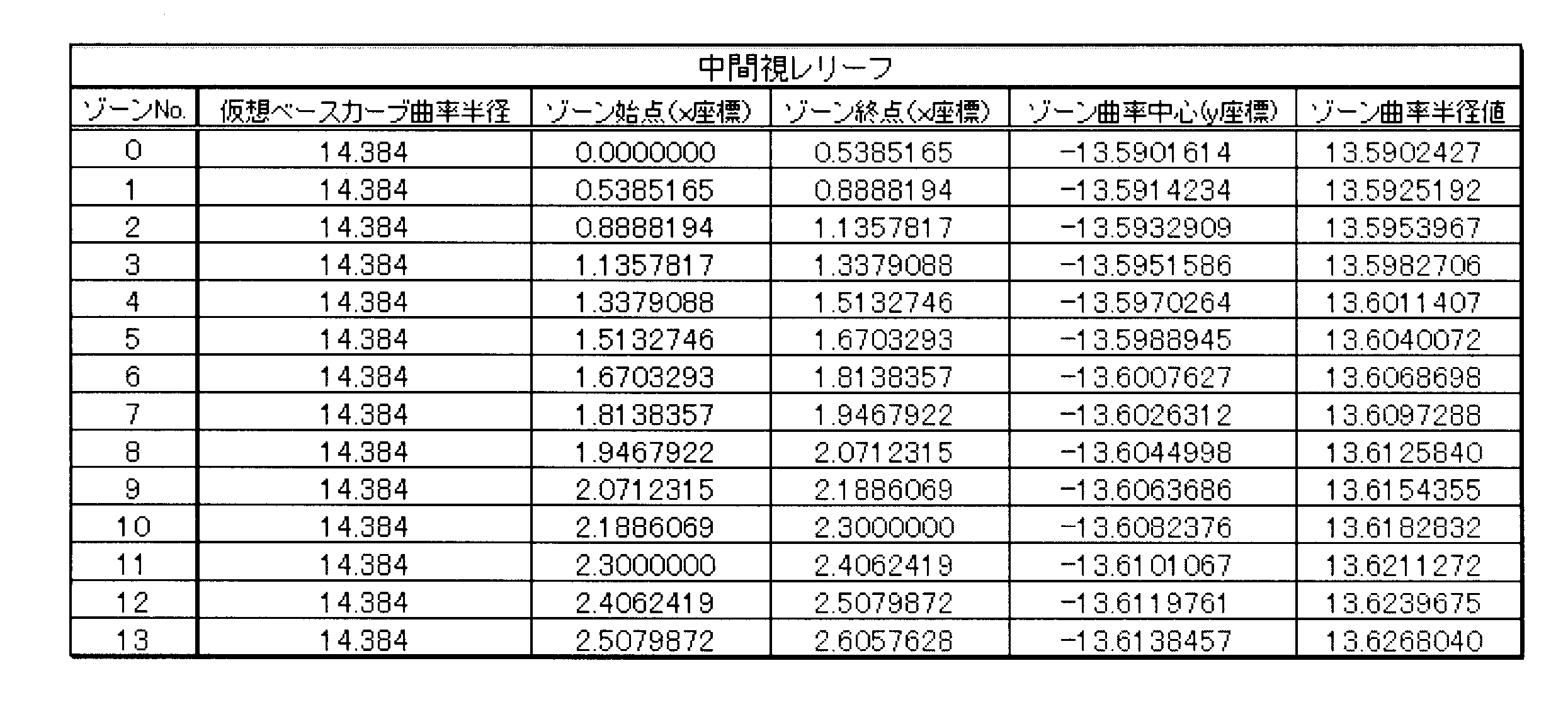
そして、前記近方視レリーフ26と同様にして、中央レリーフ高さや中央頂点Y座標を決定することが出来、幾何学的な関係から、近方視レリーフ26と同期する、中間視レリーフ28の回折面の曲率や、中心位置等の形状パラメータおよびレリーフプロファイルを得ることが出来る。表2に、中間視レリーフ28の形状パラメータを示すと共に、図9に、中間視レリーフ28のレリーフプロファイルを示す。
Then, in the same manner as the near vision relief 26, the central relief height and the central vertex Y coordinate can be determined, and the diffraction of the intermediate vision relief 28 synchronized with the near vision relief 26 is geometrically related. Shape parameters such as the curvature of the surface and the center position and the relief profile can be obtained. Table 2 shows the shape parameters of the intermediate vision relief 28, and FIG. 9 shows the relief profile of the intermediate vision relief 28.

続いて、近方視レリーフ26のレリーフプロファイルと、中間視レリーフ28のレリーフプロファイルを合算することによって、近方視レリーフ26と中間視レリーフ28が周期的に重なり合う、同期構造を有するレリーフ24のレリーフプロファイルが完成する。表3に、レリーフ24の形状パラメータを示すと共に、図10に、レリーフ24のレリーフプロファイルを示す。
Subsequently, by summing the relief profile of the near vision relief 26 and the relief profile of the intermediate vision relief 28, the relief 24 of the relief 24 having a synchronous structure in which the near vision relief 26 and the intermediate vision relief 28 overlap each other periodically. The profile is complete. Table 3 shows the shape parameters of the relief 24, and FIG. 10 shows the relief profile of the relief 24.
そして、得られたレリーフプロファイルに従って、レリーフ24を光学部前面16に形成する。レリーフ24の光学部前面16への形成は、型成形のみならず、レーザー加工やエッチング、切削等の機械加工等が適宜に採用され得る。このようにして、上記実施形態としての眼内レンズ10を得ることが出来る。
Then, according to the obtained relief profile, the relief 24 is formed on the optical unit front surface 16. For forming the relief 24 on the front surface 16 of the optical part, not only mold forming but also machining such as laser processing, etching, cutting, and the like can be appropriately employed. In this way, the intraocular lens 10 as the above embodiment can be obtained.
以上、本発明の一実施形態および製造方法について詳述してきたが、これはあくまでも例示であって、本発明は、かかる実施形態における具体的な記載によって、何等、限定的に解釈されるものではない。以下に、本発明において好適に採用され得るその他の態様を幾つか示すが、本発明が以下の態様に限定されることを示すものではないことが理解されるべきである。なお、以下の説明において、前述の実施形態と実質的に同様の部材および部位については、前述の実施形態と同様の符号を付することによって、詳細な説明を省略する。
As mentioned above, although one Embodiment of this invention and the manufacturing method were explained in full detail, this is an illustration to the last, Comprising: This invention is not interpreted limitedly by the specific description in this embodiment. Absent. Several other embodiments that can be suitably employed in the present invention are shown below, but it should be understood that the present invention is not limited to the following embodiments. In the following description, members and parts that are substantially the same as those of the above-described embodiment are denoted by the same reference numerals as those of the above-described embodiment, and detailed description thereof is omitted.
先ず、図11に、本発明の第二の実施形態としてのレリーフ50をレリーフプロファイルとして示す。本実施形態においては、近方視レリーフとしてパワー=+3.0D、中間視レリーフとしてパワー=+1.0Dの2つのレリーフが周期的に重なり合う同期構造が設定されている。なお、本実施形態におけるレリーフプロファイルは、光学部前面16のベースカーブ曲率半径=8.000mm、光学部12のパワー=+25.0D、レンズ材料屈折率=1.500、周囲媒質屈折率=1.336、設計波長=500nm、近方視レリーフのゾーン定数:a=1の条件下で得たものである。なお、格子ピッチは、近方視レリーフに比して、中間視レリーフの方が大きい。
First, FIG. 11 shows a relief 50 as a relief profile as a second embodiment of the present invention. In this embodiment, a synchronous structure is set in which two reliefs of power = + 3.0D as near vision relief and power = + 1.0D as intermediate vision relief are periodically overlapped. In this embodiment, the relief profile is as follows: the radius of curvature of the base curve of the front surface 16 of the optical unit = 8000 mm, the power of the optical unit 12 = + 25.0D, the refractive index of the lens material = 1.500, and the refractive index of the surrounding medium = 1. 336, design wavelength = 500 nm, zone constant of near vision relief: obtained under the condition of a = 1. Note that the lattice pitch is larger in the intermediate vision relief than in the near vision relief.
特に本実施形態においては、中間視レリーフの各1つのゾーンに対して、近方視レリーフが2つのレリーフ段差をもって、3つのゾーンで形成されており、換言すれば、近方視レリーフのゾーン半径の3つに1つの割合で、中間視レリーフのゾーン半径が近方視レリーフのゾーン半径と一致せしめられている。そして、近方視レリーフが重ね合わされた中間視レリーフの各ゾーンにおいて、中間視レリーフのレリーフ段差間に位置せしめられた近方視レリーフのレリーフ段差における仮想ベースカーブ面に対する高さが、ゾーン方向(図11中、左右方向)で次第に変化せしめられており、本実施形態においては、ゾーン方向で中央から離隔するにつれて次第に低くなるようにされている。なお、このようなレリーフ50も、前記第一の実施形態と同様の製造方法に従って形成することが可能である。
In particular, in this embodiment, the near vision relief is formed of three zones with two relief steps for each zone of the intermediate vision relief, in other words, the zone radius of the near vision relief. The zone radius of the intermediate vision relief is matched with the zone radius of the near vision relief at a rate of one in three. Then, in each zone of the intermediate vision relief in which the near vision relief is overlaid, the height relative to the virtual base curve surface at the relief step of the near vision relief positioned between the relief steps of the intermediate vision relief is the zone direction ( In the present embodiment, it gradually decreases as the distance from the center increases in the zone direction. Such a relief 50 can also be formed according to the same manufacturing method as in the first embodiment.
なお、図12に、本実施形態におけるレリーフ50によって得られる光軸上の回折強度について、前記第一の実施形態と同様に計算機上でシミュレートした結果を示す。図12から明らかなように、本実施形態においても、屈折面の0次光による遠方視用焦点と、近方視レリーフの回折一次光による近方視用焦点との間に、中間視レリーフの回折一次光による中間視用焦点のピークが発生すると共に、これら遠方視、近方視、および中間視の何れにおいても明瞭なピークが生ぜしめられることが確認された。
FIG. 12 shows the result of simulating on the computer the diffraction intensity on the optical axis obtained by the relief 50 in the present embodiment, as in the first embodiment. As is clear from FIG. 12, also in this embodiment, the distance of the intermediate vision relief is between the distance vision focus by the zero-order light on the refracting surface and the near vision focus by the diffracted primary light of the near vision relief. It was confirmed that the peak of the focus for intermediate vision due to the diffracted primary light was generated, and a clear peak was generated in any of these far vision, near vision, and intermediate vision.
さらに、特に本実施形態においては、中間視レリーフの回折二次光が発生する。このように、レリーフ50の設計パラメータを変更することによって、複数の中間視を生成することも可能である。また、回折のピーク強度や焦点位置は、例えば同期構造を有するレリーフ50に対して、更に周期的に重なり合うレリーフを加える等することで様々な態様が設定可能である。
Furthermore, particularly in the present embodiment, the diffracted secondary light of the relief for intermediate vision is generated. As described above, a plurality of intermediate visions can be generated by changing the design parameters of the relief 50. The diffraction peak intensity and focus position can be set in various modes by, for example, adding a relief that overlaps periodically to the relief 50 having a synchronous structure.
次に、図13に、本発明の第三の実施形態としてのレリーフ60をレリーフプロファイルとして示す。本実施形態においては、近方視レリーフとしてパワー=+3.0D、中間視レリーフとしてパワー=+1.0Dの2つのレリーフが周期的に重なり合う同期構造が設定されている。なお、格子ピッチは、近方視レリーフに比して、中間視レリーフの方が大きい。
Next, FIG. 13 shows a relief 60 as a relief profile as a third embodiment of the present invention. In this embodiment, a synchronous structure is set in which two reliefs of power = + 3.0D as near vision relief and power = + 1.0D as intermediate vision relief are periodically overlapped. Note that the lattice pitch is larger in the intermediate vision relief than in the near vision relief.
本実施形態においては、中間視レリーフの各1つのゾーンに対して、近方視レリーフが2つのレリーフ段差をもって、3つのゾーンで形成されており、換言すれば、近方視レリーフのゾーン半径の3つに1つの割合で、中間視レリーフのゾーン半径が近方視レリーフのゾーン半径と一致するようにされている。そして、近方視レリーフが重ね合わされた中間視レリーフの各ゾーンにおいて、中間視レリーフのレリーフ段差間に位置せしめられた近方視レリーフのレリーフ段差における仮想ベースカーブ面に対する高さが、ゾーン方向(図13中、左右方向)で略一定とされている。
In the present embodiment, the near vision relief is formed of three zones with two relief steps for each zone of the intermediate vision relief, in other words, the zone radius of the near vision relief. At a rate of one in three, the zone radius of the intermediate vision relief is made to coincide with the zone radius of the near vision relief. Then, in each zone of the intermediate vision relief in which the near vision relief is overlaid, the height relative to the virtual base curve surface at the relief step of the near vision relief positioned between the relief steps of the intermediate vision relief is the zone direction ( In FIG. 13, the horizontal direction is substantially constant.
このようなレリーフ60は、前記第一および第二の実施形態に比して、より簡易な方法で製造することが出来る。即ち、互いに重ね合わされる複数のレリーフの重なり合いの周期に基づいて、格子ピッチが小さい方のレリーフにおいて、格子ピッチが大きい方のレリーフが重なり合うレリーフ段差を大きくすることによって、同期構造を有するレリーフを簡易に得ることが出来る。例えば、本実施形態における近方視レリーフと中間視レリーフのパワーは前記第二の実施形態と等しいが、第二の実施形態(図11参照)から明らかなように、中間視レリーフは近方視レリーフに対して3回に1回の割合で同期する。従って、前記製造方法に従って近方視レリーフ形状を設計した後には、前記製造方法のように中間視レリーフ形状を厳密に設計せずとも、得られた近方視レリーフ形状に対して3回に1回の割合で、レリーフ段差を大きくすることによって、第二の実施形態に近いレリーフ形状を簡易に得ることが出来る。
Such a relief 60 can be manufactured by a simpler method as compared with the first and second embodiments. That is, the relief having a synchronous structure can be simplified by increasing the relief step where the relief having the larger grating pitch overlaps the relief having the smaller grating pitch, based on the overlapping period of the plurality of reliefs that are superimposed on each other. Can be obtained. For example, the power of the near vision relief and the intermediate vision relief in this embodiment is equal to that of the second embodiment, but as is clear from the second embodiment (see FIG. 11), the intermediate vision relief is near vision. Synchronize with the relief once every three times. Therefore, after designing the near vision relief shape according to the manufacturing method, the intermediate vision relief shape is not designed exactly as in the manufacturing method, but once for the obtained near vision relief shape. The relief shape close to the second embodiment can be easily obtained by increasing the relief step at the rate of rotation.
なお、図14に、本実施形態におけるレリーフ60によって得られる光軸上の回折強度について、前記第一の実施形態と同様に計算機上でシミュレートした結果を示す。図14から明らかなように、前記第二の実施形態(図12参照)に比して中間視の回折強度はやや低下するものの、本実施形態によれば、簡易な製造方法で、中間視用焦点のピークを生ぜしめ、前記第二の実施形態に近い効果が得られることが確認された。
FIG. 14 shows the result of simulating on the computer the diffraction intensity on the optical axis obtained by the relief 60 in the present embodiment, as in the first embodiment. As is apparent from FIG. 14, although the diffraction intensity of intermediate vision is slightly lower than that of the second embodiment (see FIG. 12), according to this embodiment, the intermediate manufacturing method can be used with a simple manufacturing method. It was confirmed that the peak of the focus was produced and the effect similar to the second embodiment was obtained.
次に、図15に、本発明の第四の実施形態としてのレリーフ70をレリーフプロファイルとして示す。本実施形態においては、遠方視レリーフとしてパワー=+4.0D、中間視レリーフとしてパワー=+2.0Dの2つのレリーフが周期的に重なり合う同期構造が設定されている。なお、格子ピッチは、遠方視レリーフに比して、中間視レリーフの方が大きい。
Next, FIG. 15 shows a relief 70 as a relief profile according to a fourth embodiment of the present invention. In this embodiment, a synchronous structure is set in which two reliefs of power = + 4.0D as a far vision relief and power = + 2.0D as an intermediate vision relief are periodically overlapped. Note that the lattice pitch is larger in the intermediate vision relief than in the far vision relief.
図15から明らかなように、本実施形態におけるレリーフ70は、前記第一の実施形態におけるレリーフ24(図10参照)のレリーフ高さが正負反転せしめられたものであり、各ゾーンにおいて、稜線30が谷線32よりも中央側に位置せしめられている。本実施形態によれば、屈折面の0次光が近方視用焦点に設定されると共に、遠方視レリーフの回折-1次光が遠方視用焦点に設定される一方、中間視レリーフの回折-1次光が中間視用焦点に設定される。そして、前述のように、本発明における回折一次光は、-1次光を含む絶対値としての一次光として理解される。
As is clear from FIG. 15, the relief 70 in the present embodiment is one in which the relief height of the relief 24 (see FIG. 10) in the first embodiment is reversed between the positive and negative sides. Is positioned closer to the center than the valley line 32. According to the present embodiment, the 0th-order light on the refractive surface is set as the near vision focus, and the far-field relief diffraction-first order light is set as the distance vision focus, while the intermediate vision relief diffraction. −1st order light is set as the focus for intermediate vision. As described above, the diffracted primary light in the present invention is understood as primary light as an absolute value including −1st order light.
なお、図16に、本実施形態におけるレリーフ70によって得られる光軸上の回折強度について、前記第一の実施形態と同様に計算機上でシミュレートした結果を示す。図16から明らかなように、本実施形態によれば、屈折面の0次光による近方視用焦点に加えて、遠方視レリーフの回折-1次光による遠方視用焦点のピークが発生すると共に、これら近方視用焦点と遠方視用焦点の間に、中間視レリーフの回折-1次光による中間視用焦点のピークが発生する。そして、本実施形態においても、これら遠方視、近方視、および中間視の何れにおいても明瞭なピークが生ぜしめられることが確認された。
FIG. 16 shows the result of simulating on the computer the diffraction intensity on the optical axis obtained by the relief 70 in the present embodiment, as in the first embodiment. As is apparent from FIG. 16, according to the present embodiment, in addition to the near vision focus due to the 0th order light on the refracting surface, the peak of the far vision focus due to the diffraction-first order light of the far vision relief occurs. At the same time, a peak of the intermediate vision focus due to the diffraction-first-order light of the relief of intermediate vision occurs between the near vision focus and the far vision focus. Also in this embodiment, it has been confirmed that a clear peak is generated in any of these far vision, near vision, and intermediate vision.
次に、図17に、本発明の第五の実施形態としてのレリーフ80をレリーフプロファイルとして示す。本実施形態においては、近方視レリーフとしてパワー=+3.0D、中間視レリーフとしてパワー=+1.0Dの2つのレリーフが周期的に重なり合う同期構造が設定されている。なお、格子ピッチは、近方視レリーフに比して、中間視レリーフの方が大きい。
Next, FIG. 17 shows a relief 80 as a relief profile according to a fifth embodiment of the present invention. In this embodiment, a synchronous structure is set in which two reliefs of power = + 3.0D as near vision relief and power = + 1.0D as intermediate vision relief are periodically overlapped. Note that the lattice pitch is larger in the intermediate vision relief than in the near vision relief.
本実施形態におけるレリーフ80は、前記第二の実施形態としてのレリーフ50(図11参照)に近い形状とされており、特に本実施形態においては、前記第二の実施形態としてのレリーフ50に対して、近方視レリーフのレリーフ成分のみが中央から外方に向けて0から次第に増加せしめられている。このようにすれば、近方視の回折強度を低減することが出来る。
The relief 80 in the present embodiment has a shape close to the relief 50 (see FIG. 11) as the second embodiment. In particular, in this embodiment, the relief 80 is different from the relief 50 as the second embodiment. Thus, only the relief component of the near vision relief is gradually increased from 0 toward the outside from the center. In this way, the near-field diffraction intensity can be reduced.
なお、図18に、本実施形態におけるレリーフ80によって得られる光軸上の回折強度について、前記第一の実施形態と同様に計算機上でシミュレートした結果を示す。図18から明らかなように、本実施形態によれば、前記第二の実施形態(図12参照)に比して、近方視焦点における回折強度のピークが低減されることが確認できる。
FIG. 18 shows the result of simulating on the computer the diffraction intensity on the optical axis obtained by the relief 80 in the present embodiment, as in the first embodiment. As is apparent from FIG. 18, according to the present embodiment, it can be confirmed that the peak of diffraction intensity at the near vision focus is reduced as compared with the second embodiment (see FIG. 12).
なお、前記各実施形態においては、複数のレリーフが周期的に重なり合う同期構造を有する回折格子が光学部12における光学部前面16の略全体に亘って形成されていたが、かかる回折格子は、レンズの径方向の少なくとも一部に形成されていれば良いのであって、例えば光学部前面16の径方向中間部分のみに形成されて、他の領域では一種類のレリーフだけが形成されている等しても良い。例えば、前記第一の実施形態としての眼内レンズ10に形成されたレリーフ24においては、同期構造を有する回折格子を、光学部後面18に形成することも、勿論可能である。
In each of the above embodiments, the diffraction grating having a synchronous structure in which a plurality of reliefs are periodically overlapped is formed over substantially the entire optical unit front surface 16 in the optical unit 12. For example, it is formed only at the radial intermediate portion of the optical unit front surface 16, and only one type of relief is formed in other regions. May be. For example, in the relief 24 formed in the intraocular lens 10 as the first embodiment, it is of course possible to form a diffraction grating having a synchronous structure on the optical unit rear surface 18.
加えて、同期構造を有する回折格子が形成されるレンズ表面は、屈折面に限定されない。例えば、図19にモデル的に示す、本発明の異なる態様としての眼内レンズの光学部100のように、両表面が平面102、104とされた一方の平面102に回折格子22を形成しても良いし、或いは、図20にモデル的に示す、本発明の更に異なる態様としての眼内レンズの光学部110のように、一方の表面が平面112とされて、他方の表面が屈折面としての湾曲面114とされた平面112に回折格子22を形成する等しても良い。
In addition, the lens surface on which the diffraction grating having a synchronous structure is formed is not limited to a refractive surface. For example, a diffraction grating 22 is formed on one plane 102 having both surfaces 102 and 104 as shown in FIG. 19 as an optical part 100 of an intraocular lens as a different embodiment of the present invention. Or, like the optical part 110 of the intraocular lens as a further different aspect of the present invention shown as a model in FIG. 20, one surface is a flat surface 112 and the other surface is a refracting surface. The diffraction grating 22 may be formed on the flat surface 112 that is the curved surface 114.
更にまた、収差軽減等の目的のために、例えば特開2001-42112号公報等に記載のように、分散が異なる二つの材質からなる積層面に、本発明にかかる回折格子を形成することも可能である。
Furthermore, for the purpose of reducing aberrations, the diffraction grating according to the present invention may be formed on a laminated surface made of two materials having different dispersions as described in, for example, Japanese Patent Laid-Open No. 2001-42112. Is possible.
なお、前記第一の実施形態に従う実施例(図6参照)に対する比較例1として、従来構造に従う2焦点レンズのレリーフ形状によって得られる回折強度について実施例と同様に計算機上でシミュレートした。比較例1のレリーフ形状としては、近方視用の+4.00Dの屈折力を有する形状を設定した。かかるシミュレート結果を、図21に示す。公知のように、従来構造に従う比較例1においては、実施例と異なり、屈折面の0次光と、近方視レリーフの回折一次光とによる2つのピークのみ生ぜしめられることが確認出来る。
In addition, as Comparative Example 1 with respect to the example according to the first embodiment (see FIG. 6), the diffraction intensity obtained by the relief shape of the bifocal lens according to the conventional structure was simulated on a computer in the same manner as in the example. As the relief shape of Comparative Example 1, a shape having a refractive power of +4.00 D for near vision was set. The simulation result is shown in FIG. As is well known, it can be confirmed that, in the first comparative example according to the conventional structure, only two peaks are generated by the zero-order light of the refractive surface and the diffracted primary light of the near vision relief, unlike the example.
更に、シミュレート結果の信頼性を高めるために、波動光学設計・解析ソフトウェア(LightTrans社製の商品名:Virtual Lab)を用いて、実施例に従うレリーフ形状と、比較例1に従うレリーフ形状について、回折強度のピークの生成を検証した。かかる検証結果を、実施例について図22(a)に、比較例1について図22(b)に示す。図22から明らかなように、本シミュレートにおいても、本発明に従う構造とされた実施例によれば、従来構造とは異なり、遠方視焦点と近方視焦点の間に中間視焦点の強いピークが発生することが確認出来た。
Furthermore, in order to increase the reliability of the simulation result, the diffraction shape of the relief shape according to the example and the relief shape according to Comparative Example 1 is diffracted using wave optical design / analysis software (product name: Virtual Lab, manufactured by LightTrans). Intensity peak generation was verified. The verification results are shown in FIG. 22A for the example and FIG. 22B for the comparative example 1. As is clear from FIG. 22, in this simulation, according to the embodiment having the structure according to the present invention, unlike the conventional structure, the peak of the intermediate vision focus is strong between the distance vision focus and the near vision focus. Was confirmed to occur.
また、比較例2として、近方視レリーフと中間視レリーフを同期させることなく単に重ね合わせた、非同期構造のレリーフ形状を有する眼内レンズを用意した。比較例2は、バイコンベックス形状の眼内レンズにおいて、パワー=+20.0D、レンズ材料屈折率=1.500、周囲媒質屈折率=1.336、設計波長=500nmとして、パワー=+4.00Dの近方視レリーフおよびパワー=+2.00Dの中間視レリーフを、何れのゾーン定数も1に設定して、互いに同期しない形状で重ね合わせてレリーフ形状を設定し、かかるレリーフ形状を光学部前面に形成した。図23に近方視レリーフを、図24に中間視レリーフのレリーフプロファイルを示す。そして、図25に、これら近方視レリーフと中間視レリーフが互いに同期することなく重ね合わされた、比較例2としてのレリーフプロファイルを示すと共に、図26に、かかる比較例2のレリーフ形状によって得られる回折強度のシミュレート結果を示す。図26から明らかなように、複数のレリーフ形状を単に重ね合わせた比較例2においては、屈折面による0次光、近方視レリーフによる回折一次光、中間視レリーフによる回折一次光の何れも明瞭なピークの発生が認められず、意図しない次数光の発生も引き起こすことが確認された。これにより、複数のレリーフが互いに周期的に重なり合う同期構造を設定する本発明の有用性が明らかとされた。
Further, as Comparative Example 2, an intraocular lens having a relief shape with an asynchronous structure in which the near vision relief and the intermediate vision relief were simply overlapped without being synchronized was prepared. Comparative Example 2 is a biconvex intraocular lens with power = + 20.0D, lens material refractive index = 1.500, ambient medium refractive index = 1.336, design wavelength = 500 nm, and power = + 4.00D. Set the relief shape by overlapping the near vision relief and the intermediate vision relief with power = + 2.00D with the zone constants set to 1 and not synchronizing with each other, and forming the relief shape on the front of the optical unit did. FIG. 23 shows a relief for near vision, and FIG. 24 shows a relief profile for relief for intermediate vision. FIG. 25 shows a relief profile as a comparative example 2 in which the near vision relief and the intermediate vision relief are overlapped without being synchronized with each other, and FIG. 26 is obtained by the relief shape of the comparative example 2. The simulation result of diffraction intensity is shown. As is clear from FIG. 26, in Comparative Example 2 in which a plurality of relief shapes are simply superimposed, all of the zero-order light from the refractive surface, the diffracted primary light from the near vision relief, and the diffracted primary light from the intermediate vision relief are clear. It was confirmed that no significant peak was observed and that unintended order light was also generated. Thus, the usefulness of the present invention for setting a synchronous structure in which a plurality of reliefs periodically overlap each other has been clarified.
10:眼内レンズ、12:光学部、16:光学部前面、20:レンズ中心軸、22:回折格子、24:レリーフ、26:近方視レリーフ、28:中間視レリーフ
10: intraocular lens, 12: optical unit, 16: front surface of optical unit, 20: lens central axis, 22: diffraction grating, 24: relief, 26: near vision relief, 28: intermediate vision relief
Claims (22)
- レンズ表面に対して同心円状に延びるレリーフをもった回折格子を設けた水晶体嚢内に配設される無水晶体眼内レンズの製造方法であって、
前記レリーフとして、それぞれの回折一次光が互いに異なる焦点距離を与える複数種類のレリーフを採用すると共に、レンズの径方向の少なくとも一部の領域において少なくとも二種類のレリーフを重ねて設定し、且つ、それらの重ねて設定したレリーフにおける格子ピッチが最大のレリーフの各格子ピッチに対して、他のレリーフにおける格子ピッチが周期的に重なり合う同期構造を設定して、得られたレリーフを前記レンズ表面に形成することを特徴とする無水晶体眼内レンズの製造方法。 A manufacturing method of an aphasic intraocular lens disposed in a lens capsule provided with a diffraction grating having a relief extending concentrically with respect to a lens surface,
As the relief, a plurality of types of relief in which each diffracted primary light gives different focal lengths, and at least two types of reliefs are set to overlap in at least a partial region in the radial direction of the lens, and these For each grating pitch of the relief having the maximum grating pitch in the relief set by overlapping, a synchronous structure in which the grating pitches in other reliefs periodically overlap is set, and the obtained relief is formed on the lens surface. A manufacturing method for an aphakic intraocular lens. - 前記レンズの屈折面による0次光に対して、前記複数種類のレリーフによる何れの回折一次光の焦点距離とも異なる焦点距離を設定する請求項1に記載の無水晶体眼内レンズの製造方法。 2. The method for manufacturing an aphakic intraocular lens according to claim 1, wherein a focal length different from a focal length of any diffracted primary light by the plurality of types of relief is set for zero-order light from the refractive surface of the lens.
- 前記レリーフを形成する前記レンズ表面が、前記屈折面である請求項2に記載の無水晶体眼内レンズの製造方法。 3. The method for manufacturing an aphakic intraocular lens according to claim 2, wherein the lens surface forming the relief is the refractive surface.
- 前記格子ピッチが最大のレリーフのレリーフ段差であって、前記複数のレリーフが重なった各レリーフ段差の大きさが、ゾーン方向で一定となるように形成する請求項1乃至3の何れか一項に記載の無水晶体眼内レンズの製造方法。 The relief step of the relief having the largest lattice pitch, and the size of each relief step where the plurality of reliefs overlap is formed to be constant in the zone direction. The manufacturing method of the aphakic intraocular lens of description.
- 前記複数のレリーフを重ねて設定した径方向の領域には、前記格子ピッチが最大のレリーフの各一つのゾーンにおいて、別の種類の前記レリーフが少なくとも二つのレリーフ段差をもって形成され、且つそれら少なくとも二つのレリーフ段差における前記ベース表面に対する高さがゾーン方向で次第に変化するように設定する請求項4に記載の無水晶体眼内レンズの製造方法。 In the radial region set by overlapping the plurality of reliefs, another type of the relief is formed with at least two relief steps in each one zone of the relief having the largest lattice pitch, and at least two of them. The method for manufacturing an aphakic intraocular lens according to claim 4, wherein the height relative to the base surface at one relief step is set to gradually change in the zone direction.
- 前記複数のレリーフを重ねて設定した径方向の領域には、前記格子ピッチが最大のレリーフの各一つのゾーンにおいて、別の種類の前記レリーフが少なくとも二つのレリーフ段差をもって形成され、且つそれら少なくとも二つのレリーフ段差における前記ベース表面に対する高さがゾーン方向で一定となるように設定する請求項4に記載の無水晶体眼内レンズの製造方法。 In the radial region set by overlapping the plurality of reliefs, another type of the relief is formed with at least two relief steps in each one zone of the relief having the largest lattice pitch, and at least two of them. The method for manufacturing an aphakic intraocular lens according to claim 4, wherein the height of the two relief steps relative to the base surface is set to be constant in the zone direction.
- 複数種類の前記レリーフが、何れも、鋭角の頂角をもった断面形状で周方向に延びる稜線と鋭角の夾角をもった断面形状で周方向に延びる谷線とを有している請求項1乃至6の何れか一項に記載の無水晶体眼内レンズの製造方法。 The plurality of types of reliefs each have a ridge line extending in the circumferential direction with a cross-sectional shape having an acute apex angle and a valley line extending in the circumferential direction with a cross-sectional shape having an acute depression angle. The manufacturing method of the aphakic intraocular lens as described in any one of thru | or 6.
- 前記レンズの屈折面による0次光を遠方視用焦点に設定する一方、一つの種類の前記レリーフによる回折一次光を近方視用焦点に設定すると共に、別の種類の前記レリーフによる回折一次光を中間視用焦点に設定する請求項1乃至7の何れか一項に記載の無水晶体眼内レンズの製造方法。 While the zero-order light from the refracting surface of the lens is set as the focal point for far vision, the diffracted primary light from one type of relief is set as the focal point for near vision, and the diffracted primary light from another type of relief is set. The method for manufacturing an aphakic intraocular lens according to any one of claims 1 to 7, wherein is set as a focus for intermediate vision.
- 前記レンズの屈折面による0次光を近方視用焦点に設定する一方、一つの種類の前記レリーフによる回折一次光を遠方視用焦点に設定すると共に、別の種類の前記レリーフによる回折一次光を中間視用焦点に設定する請求項1乃至7の何れか一項に記載の無水晶体眼内レンズの製造方法。 The zero-order light from the refracting surface of the lens is set as a focus for near vision, while the diffracted primary light from one type of relief is set as the focus for far vision, and the diffracted primary light from another type of relief is set. The method for manufacturing an aphakic intraocular lens according to any one of claims 1 to 7, wherein is set as a focus for intermediate vision.
- 複数の前記レリーフは、一方の該レリーフのゾーン定数をA、他方の該レリーフのゾーン定数をa,一方の該レリーフのゾーン番号をM、他方の該レリーフのゾーン番号をm、一方の該レリーフの焦点距離/他方の該レリーフの焦点距離をNとして、下式:
A=(2(m-NM)+a)/N
を満足するように設定されている請求項1乃至9の何れか一項に記載の無水晶体眼内レンズの製造方法。 The plurality of the reliefs have a zone constant of one of the reliefs as A, a zone constant of the other relief as a, a zone number of one of the reliefs as M, a zone number of the other relief as m, and one of the reliefs Where N is the focal length of the other relief / the other relief:
A = (2 (m−NM) + a) / N
The method for manufacturing an aphakic intraocular lens according to any one of claims 1 to 9, which is set to satisfy the following. - 複数の前記レリーフは、レリーフ段差の高さ寸法をD、設計波長をλ、前記光学材料の屈折率をNlens、周囲媒質屈折率をNmed として、下式:
D≦λ/(Nlens-Nmed )
を満足するように設定されている請求項1乃至10の何れか一項に記載の無水晶体眼内レンズの製造方法。 The plurality of reliefs are represented by the following formula, where D is the height of the relief step, λ is the design wavelength, N lens is the refractive index of the optical material, and N med is the refractive index of the surrounding medium.
D ≦ λ / (N lens -N med )
The manufacturing method of the aphakic intraocular lens according to any one of claims 1 to 10, which is set to satisfy the following. - レンズ表面に対して同心円状に延びるレリーフをもった回折格子が設けられた水晶体嚢内に配設される無水晶体眼内レンズであって、
レンズの径方向の少なくとも一部の領域において、それぞれの回折一次光が互いに異なる焦点距離を与える少なくとも二種類のレリーフが重ねて設定されており、且つ、それらの重ねて設定されたレリーフにおける格子ピッチが最大のレリーフの各格子ピッチに対して、他のレリーフにおける格子ピッチが周期的に重なり合う周期構造を有することを特徴とする無水晶体眼内レンズ。 A lensless intraocular lens disposed in a lens capsule provided with a diffraction grating having a relief extending concentrically with respect to the lens surface,
In at least a partial region in the radial direction of the lens, at least two types of relief in which each diffracted primary light gives different focal lengths are set to be overlapped, and the grating pitch in the overlapped relief is set. A lens-free intraocular lens having a periodic structure in which the grating pitches of other reliefs periodically overlap with each grating pitch of the largest relief. - 前記レンズの屈折面による0次光に対して、前記複数種類のレリーフによる何れの回折一次光の焦点距離とも異なる焦点距離が設定されている請求項12に記載の無水晶体眼内レンズ。 The aphakic intraocular lens according to claim 12, wherein a focal length different from a focal length of any diffracted primary light by the plurality of types of relief is set with respect to the zero-order light from the refractive surface of the lens.
- 前記レリーフが形成される前記レンズ表面が、前記屈折面である請求項13に記載の無水晶体眼内レンズ。 The aphakic intraocular lens according to claim 13, wherein the lens surface on which the relief is formed is the refractive surface.
- 前記格子ピッチが最大のレリーフのレリーフ段差であって、前記複数のレリーフが重なった各レリーフ段差の大きさが、ゾーン方向で一定とされている請求項12乃至14の何れか一項に記載の無水晶体眼内レンズ。 15. The relief step of the relief having the largest lattice pitch, and the size of each relief step in which the plurality of reliefs are overlapped is made constant in the zone direction. Aphakic intraocular lens.
- 前記複数のレリーフを重ねて設定した径方向の領域には、前記格子ピッチが最大のレリーフの各一つのゾーンにおいて、別の種類の前記レリーフが少なくとも二つのレリーフ段差をもって形成され、且つそれら少なくとも二つのレリーフ段差における前記ベース表面に対する高さがゾーン方向で次第に変化している請求項15に記載の無水晶体眼内レンズ。 In the radial region set by overlapping the plurality of reliefs, another type of the relief is formed with at least two relief steps in each one zone of the relief having the largest lattice pitch, and at least two of them. The aphakic intraocular lens according to claim 15, wherein the height of the two relief steps with respect to the base surface gradually changes in the zone direction.
- 前記複数のレリーフを重ねて設定した径方向の領域には、前記格子ピッチが最大のレリーフの各一つのゾーンにおいて、別の種類の前記レリーフが少なくとも二つのレリーフ段差をもって形成され、且つそれら少なくとも二つのレリーフ段差における前記ベース表面に対する高さがゾーン方向で一定とされている請求項15に記載の無水晶体眼内レンズ。 In the radial region set by overlapping the plurality of reliefs, another type of the relief is formed with at least two relief steps in each one zone of the relief having the largest lattice pitch, and at least two of them. The aphakic intraocular lens according to claim 15, wherein the height of the two relief steps relative to the base surface is constant in the zone direction.
- 複数種類の前記レリーフが、何れも、鋭角の頂角をもった断面形状で周方向に延びる稜線と鋭角の夾角をもった断面形状で周方向に延びる谷線とを有している請求項12乃至17の何れか一項に記載の無水晶体眼内レンズ。 The plurality of types of reliefs each have a ridge line extending in the circumferential direction with a cross-sectional shape having an acute apex angle and a valley line extending in the circumferential direction with a cross-sectional shape having an acute depression angle. The aphakic intraocular lens according to any one of 1 to 17.
- 前記レンズの屈折面による0次光が遠方視用焦点に設定されている一方、一つの種類の前記レリーフによる回折一次光が近方視用焦点に設定されていると共に、別の種類の前記レリーフによる回折一次光が中間視用焦点に設定されている請求項12乃至18の何れか一項に記載の無水晶体眼内レンズ。 While the zero-order light from the refractive surface of the lens is set as a far vision focus, the diffracted primary light from one type of the relief is set as a near vision focus, and another type of the relief. 19. The aphakic intraocular lens according to any one of claims 12 to 18, wherein the diffracted primary light by is set to a focus for intermediate vision.
- 前記レンズの屈折面による0次光が近方視用焦点に設定されている一方、一つの種類の前記レリーフによる回折一次光が遠方視用焦点に設定されていると共に、別の種類の前記レリーフによる回折一次光が中間視用焦点に設定されている請求項12乃至18の何れか一項に記載の無水晶体眼内レンズ。 While the zero-order light from the refractive surface of the lens is set as a focus for near vision, the diffracted primary light from one type of the relief is set as a focus for far vision, and another type of the relief is used. 19. The aphakic intraocular lens according to any one of claims 12 to 18, wherein the diffracted primary light by is set to a focus for intermediate vision.
- 複数の前記レリーフが、一方の該レリーフのゾーン定数をA、他方の該レリーフのゾーン定数をa,一方の該レリーフのゾーン番号をM、他方の該レリーフのゾーン番号をm、他方の該レリーフの焦点距離/一方の該レリーフの焦点距離をNとして、下式:
A=(2(m-NM)+a)/N
を満足するように形成されている請求項12乃至20の何れか一項に記載の無水晶体眼内レンズ。 A plurality of the reliefs have a zone constant of one relief A, a zone constant of the other relief a, a zone number of one relief M, a zone number of the other relief m, and the other relief The focal length of one of the reliefs, where N is the focal length of the relief,
A = (2 (m−NM) + a) / N
The aphakic intraocular lens according to any one of claims 12 to 20, which is formed so as to satisfy the above. - 複数の前記レリーフが、レリーフ段差の高さ寸法をD、設計波長をλ、前記光学材料の屈折率をNlens、周囲媒質屈折率をNmed として、下式:
D≦λ/(Nlens-Nmed )
を満足するように形成されている請求項12乃至21の何れか一項に記載の無水晶体眼内レンズ。 The plurality of reliefs are represented by the following formula, where D is the height of the relief step, λ is the design wavelength, N lens is the refractive index of the optical material, and N med is the refractive index of the surrounding medium.
D ≦ λ / (N lens -N med )
The aphakic intraocular lens according to any one of claims 12 to 21, which is formed so as to satisfy the above.
Priority Applications (6)
| Application Number | Priority Date | Filing Date | Title |
|---|---|---|---|
| ES09837427.5T ES2551158T3 (en) | 2009-01-06 | 2009-04-08 | Method to manufacture a phakic intraocular lens |
| US13/142,995 US8500805B2 (en) | 2009-01-06 | 2009-04-08 | Method for manufacturing aphakic intraocular lens |
| DK09837427.5T DK2377493T3 (en) | 2009-01-06 | 2009-04-08 | METHOD FOR PRODUCING AFAKISK intraocular lens |
| SI200931294T SI2377493T1 (en) | 2009-01-06 | 2009-04-08 | Method for manufacturing aphakic intraocular lens |
| PL09837427T PL2377493T3 (en) | 2009-01-06 | 2009-04-08 | Method for manufacturing aphakic intraocular lens |
| EP09837427.5A EP2377493B1 (en) | 2009-01-06 | 2009-04-08 | Method for manufacturing aphakic intraocular lens |
Applications Claiming Priority (2)
| Application Number | Priority Date | Filing Date | Title |
|---|---|---|---|
| JP2009-001169 | 2009-01-06 | ||
| JP2009001169A JP5342244B2 (en) | 2009-01-06 | 2009-01-06 | Method for manufacturing aphakic intraocular lens |
Publications (1)
| Publication Number | Publication Date |
|---|---|
| WO2010079537A1 true WO2010079537A1 (en) | 2010-07-15 |
Family
ID=42316317
Family Applications (1)
| Application Number | Title | Priority Date | Filing Date |
|---|---|---|---|
| PCT/JP2009/001631 WO2010079537A1 (en) | 2009-01-06 | 2009-04-08 | Method for manufacturing aphakic intraocular lens |
Country Status (11)
| Country | Link |
|---|---|
| US (1) | US8500805B2 (en) |
| EP (1) | EP2377493B1 (en) |
| JP (1) | JP5342244B2 (en) |
| DE (1) | DE202009018881U1 (en) |
| DK (1) | DK2377493T3 (en) |
| ES (1) | ES2551158T3 (en) |
| HU (1) | HUE027966T2 (en) |
| PL (1) | PL2377493T3 (en) |
| PT (1) | PT2377493E (en) |
| SI (1) | SI2377493T1 (en) |
| WO (1) | WO2010079537A1 (en) |
Cited By (6)
| Publication number | Priority date | Publication date | Assignee | Title |
|---|---|---|---|---|
| JP2015217292A (en) * | 2014-05-15 | 2015-12-07 | ノバルティス アーゲー | Multifocal diffractive ophthalmic lens using suppressed diffractive order |
| US9320594B2 (en) | 2009-02-12 | 2016-04-26 | The Arizona Board Of Regents On Behalf Of The University Of Arizona | Diffractive trifocal lens |
| EP2744451B1 (en) * | 2011-08-19 | 2017-09-20 | Oculentis Holding B.V. | Intraocular lens |
| US11129707B2 (en) | 2015-08-12 | 2021-09-28 | Physiol S.A. | Trifocal intraocular lens with extended range of vision and correction of longitudinal chromatic aberration |
| JP2022500223A (en) * | 2018-09-13 | 2022-01-04 | ハニータ レンズ アール.シー.エー | Multifocal intraocular lens |
| JP7568629B2 (ja) | 2018-09-13 | 2024-10-16 | ハニータ レンズ リミテッド | 多焦点眼内レンズ |
Families Citing this family (39)
| Publication number | Priority date | Publication date | Assignee | Title |
|---|---|---|---|---|
| JP4551489B2 (en) * | 2009-01-06 | 2010-09-29 | 株式会社メニコン | Manufacturing method of diffractive lens |
| BE1019161A5 (en) * | 2010-01-26 | 2012-04-03 | Physiol | INTRAOCULAR LENS. |
| US9658471B2 (en) | 2012-02-09 | 2017-05-23 | Menicon Co., Ltd. | Multifocal ophthalmic lens having a focal point formation region and a cancellation region and manufacturing method thereof |
| EP2813881B1 (en) * | 2012-02-09 | 2016-07-06 | Menicon Co., Ltd. | Diffraction-type multifocal ophtalmic lens and manufacturing method therefor |
| EP2890287B1 (en) | 2012-08-31 | 2020-10-14 | Amo Groningen B.V. | Multi-ring lens, systems and methods for extended depth of focus |
| DE102013216015B4 (en) * | 2013-08-13 | 2021-01-28 | Carl Zeiss Meditec Ag | Multifocal eye lens with optical zones at least partially revolving around a main optical axis |
| US11000366B2 (en) | 2014-05-15 | 2021-05-11 | Alcon Inc. | Multifocal diffractive ophthalmic lens |
| US10285806B2 (en) * | 2014-05-15 | 2019-05-14 | Novartis Ag | Multifocal diffractive ophthalmic lens |
| EP3179294B1 (en) | 2014-08-08 | 2024-04-17 | Menicon Co., Ltd. | Method for producing diffractive multifocal ophthalmic lens and diffractive multifocal ophthalmic lens |
| JP6412556B2 (en) * | 2014-08-08 | 2018-10-24 | 株式会社メニコン | Diffraction multifocal lens and method of manufacturing diffractive multifocal lens |
| WO2017056305A1 (en) | 2015-10-01 | 2017-04-06 | 株式会社メニコン | Diffractive multi-focal ocular lens and method for manufacturing diffractive multi-focal ocular lens |
| HUE038672T2 (en) * | 2015-10-02 | 2018-11-28 | Rayner Intraocular Lenses Ltd | Multifocal lens and method of manufacturing the same |
| HUE038956T2 (en) | 2015-10-02 | 2018-12-28 | Rayner Intraocular Lenses Ltd | Multifocal lens |
| JP6913035B2 (en) | 2016-02-09 | 2021-08-04 | 株式会社メニコン | Method for Manufacturing Diffractive Multifocal Lens for Eyes and Diffractive Multifocal Lens for Eyes |
| CA3013858A1 (en) | 2016-02-09 | 2017-08-17 | Amo Groningen B.V. | Progressive power intraocular lens, and methods of use and manufacture |
| US10675146B2 (en) * | 2016-02-24 | 2020-06-09 | Alcon Inc. | Multifocal lens having reduced visual disturbances |
| US10568734B2 (en) * | 2016-03-03 | 2020-02-25 | Novartis Ag | Adjusting the apodization pattern for diffractive IOLs |
| US10531950B2 (en) | 2016-11-16 | 2020-01-14 | Tatvum LLC | Intraocular lens having an extended depth of focus |
| KR20230144098A (en) * | 2017-02-14 | 2023-10-13 | 데이브, 자그래트 나타바르 | Diffractive multifocal implantable lens device |
| US11497599B2 (en) | 2017-03-17 | 2022-11-15 | Amo Groningen B.V. | Diffractive intraocular lenses for extended range of vision |
| US10433951B2 (en) * | 2017-05-22 | 2019-10-08 | Rxsight, Inc. | Depth of focus and visual acuity using colorized apodization of intra-ocular lenses |
| US11523897B2 (en) | 2017-06-23 | 2022-12-13 | Amo Groningen B.V. | Intraocular lenses for presbyopia treatment |
| EP3646110A1 (en) | 2017-06-28 | 2020-05-06 | Amo Groningen B.V. | Diffractive lenses and related intraocular lenses for presbyopia treatment |
| CA3068351A1 (en) | 2017-06-28 | 2019-01-03 | Amo Groningen B.V. | Extended range and related intraocular lenses for presbyopia treatment |
| US11327210B2 (en) * | 2017-06-30 | 2022-05-10 | Amo Groningen B.V. | Non-repeating echelettes and related intraocular lenses for presbyopia treatment |
| ES2803225T3 (en) | 2017-07-26 | 2021-01-25 | Vsy Biyoteknoloji Ve Ilac Sanayi Anonim Sirketi | Ophthalmic multifocal diffractive lens |
| BR112020007723A2 (en) * | 2017-12-28 | 2020-10-13 | Medicontur Orvostechnikai Kft. | artificial trifocal ophthalmic lens and method for its production |
| US11324588B2 (en) | 2018-04-09 | 2022-05-10 | Mediphacos Industrias Medicas S/A | Diffractive intraocular lens |
| US11106056B2 (en) | 2019-03-28 | 2021-08-31 | Aizhong Zhang | Subzonal multifocal diffractive lens |
| CN112198577B (en) * | 2019-10-23 | 2022-04-26 | 东莞东阳光医疗智能器件研发有限公司 | Ophthalmic lens |
| CN115380239A (en) | 2019-12-30 | 2022-11-22 | 阿莫格罗宁根私营有限公司 | Lens with irregular width diffraction profile for vision treatment |
| US11719958B2 (en) | 2020-02-04 | 2023-08-08 | Valdemar Portney | Multi-chamber switchable optical element |
| EP3939543A1 (en) * | 2020-07-15 | 2022-01-19 | Hoya Corporation | Multifocal lens |
| WO2022039683A1 (en) | 2020-08-21 | 2022-02-24 | Vsy Biyoteknoloji Ve Ilac Sanayi A.S. | A zonal diffractive ocular lens |
| WO2022039682A1 (en) | 2020-08-21 | 2022-02-24 | Vsy Biyoteknoloji Ve Ilac Sanayi A.S. | A zonal diffractive ocular lens |
| JP2024515002A (en) | 2021-02-19 | 2024-04-04 | ヴェセイェ・ビヨテクノロジ・ヴェ・イラチ・サナイ・アノニム・シルケティ | Adaptive Multifocal Diffractive Ophthalmic Lenses |
| US20230314838A1 (en) * | 2022-04-01 | 2023-10-05 | Valdemar Portney | Diffractive multifocal small aperture ophthalmic lens |
| DE102022209520A1 (en) | 2022-09-12 | 2024-03-14 | Carl Zeiss Meditec Ag | OPHTHALMIC LENS AND METHOD FOR DESIGNING AND MANUFACTURING SAME |
| WO2024144487A1 (en) | 2022-12-30 | 2024-07-04 | Vsy Biyoteknoloji Ve Ilac Sanayi A.S. | A multifocal diffractive ocular lens with adaptive power |
Citations (7)
| Publication number | Priority date | Publication date | Assignee | Title |
|---|---|---|---|---|
| JPH0335502U (en) * | 1989-08-08 | 1991-04-08 | ||
| US5121980A (en) | 1989-04-19 | 1992-06-16 | Cohen Allen L | Small aperture multifocal |
| JP2001042112A (en) | 1999-07-28 | 2001-02-16 | Canon Inc | Diffraction optical device and optical system using the device |
| US7188949B2 (en) | 2004-10-25 | 2007-03-13 | Advanced Medical Optics, Inc. | Ophthalmic lens with multiple phase plates |
| US20070182924A1 (en) * | 2006-02-09 | 2007-08-09 | Alcon Manufacturing, Ltd. | Pseudo-accommodative IOL having multiple diffractive patterns |
| JP2008043752A (en) * | 2006-08-02 | 2008-02-28 | Alcon Manufacturing Ltd | Apodized diffractive iol having frustrated diffractive region |
| JP2008517731A (en) * | 2004-10-25 | 2008-05-29 | アドバンスト メディカル オプティクス, インコーポレーテッド | Ophthalmic lens having a plurality of phase plates |
Family Cites Families (9)
| Publication number | Priority date | Publication date | Assignee | Title |
|---|---|---|---|---|
| WO1988009950A1 (en) * | 1987-06-01 | 1988-12-15 | Valdemar Portney | Multifocal ophthalmic lens |
| US5122903A (en) * | 1989-03-15 | 1992-06-16 | Omron Corporation | Optical device and optical pickup device using the same |
| US5283690A (en) * | 1989-04-04 | 1994-02-01 | Sharp Kabushiki Kaisha | Optical diffraction grating element |
| US5178636A (en) | 1990-05-14 | 1993-01-12 | Iolab Corporation | Tuned fresnel lens for multifocal intraocular applications including small incision surgeries |
| US5589982A (en) | 1994-06-03 | 1996-12-31 | Rochester Photonics Corporation | Polychromatic diffractive lens |
| JP4587418B2 (en) * | 2000-09-27 | 2010-11-24 | キヤノン株式会社 | Diffractive optical element and optical system having the diffractive optical element |
| EP1279992A3 (en) | 2001-07-28 | 2004-12-01 | ESCHENBACH OPTIK GmbH + Co. | Lens to be built in into a spectacle frame |
| US7025456B2 (en) | 2004-08-20 | 2006-04-11 | Apollo Optical Systems, Llc | Diffractive lenses for vision correction |
| JP4551489B2 (en) | 2009-01-06 | 2010-09-29 | 株式会社メニコン | Manufacturing method of diffractive lens |
-
2009
- 2009-01-06 JP JP2009001169A patent/JP5342244B2/en active Active
- 2009-04-08 PT PT98374275T patent/PT2377493E/en unknown
- 2009-04-08 EP EP09837427.5A patent/EP2377493B1/en active Active
- 2009-04-08 DK DK09837427.5T patent/DK2377493T3/en active
- 2009-04-08 ES ES09837427.5T patent/ES2551158T3/en active Active
- 2009-04-08 WO PCT/JP2009/001631 patent/WO2010079537A1/en active Application Filing
- 2009-04-08 DE DE202009018881.7U patent/DE202009018881U1/en not_active Expired - Lifetime
- 2009-04-08 PL PL09837427T patent/PL2377493T3/en unknown
- 2009-04-08 SI SI200931294T patent/SI2377493T1/en unknown
- 2009-04-08 US US13/142,995 patent/US8500805B2/en active Active
- 2009-04-08 HU HUE09837427A patent/HUE027966T2/en unknown
Patent Citations (7)
| Publication number | Priority date | Publication date | Assignee | Title |
|---|---|---|---|---|
| US5121980A (en) | 1989-04-19 | 1992-06-16 | Cohen Allen L | Small aperture multifocal |
| JPH0335502U (en) * | 1989-08-08 | 1991-04-08 | ||
| JP2001042112A (en) | 1999-07-28 | 2001-02-16 | Canon Inc | Diffraction optical device and optical system using the device |
| US7188949B2 (en) | 2004-10-25 | 2007-03-13 | Advanced Medical Optics, Inc. | Ophthalmic lens with multiple phase plates |
| JP2008517731A (en) * | 2004-10-25 | 2008-05-29 | アドバンスト メディカル オプティクス, インコーポレーテッド | Ophthalmic lens having a plurality of phase plates |
| US20070182924A1 (en) * | 2006-02-09 | 2007-08-09 | Alcon Manufacturing, Ltd. | Pseudo-accommodative IOL having multiple diffractive patterns |
| JP2008043752A (en) * | 2006-08-02 | 2008-02-28 | Alcon Manufacturing Ltd | Apodized diffractive iol having frustrated diffractive region |
Cited By (19)
| Publication number | Priority date | Publication date | Assignee | Title |
|---|---|---|---|---|
| US11199725B2 (en) | 2009-02-12 | 2021-12-14 | Arizona Board Of Regents On Behalf Of The University Of Arizona | Diffractive trifocal lens |
| US9320594B2 (en) | 2009-02-12 | 2016-04-26 | The Arizona Board Of Regents On Behalf Of The University Of Arizona | Diffractive trifocal lens |
| US10209533B2 (en) | 2009-02-12 | 2019-02-19 | The Arizona Board Of Regents On Behalf Of The University Of Arizona | Diffractive trifocal lens |
| US11693260B2 (en) | 2009-02-12 | 2023-07-04 | Arizona Board Of Regents On Behalf Of The University Of Arizona | Diffractive trifocal lens |
| EP2396683B1 (en) | 2009-02-12 | 2020-04-08 | The Arizona Board Of Regents On Behalf Of The University Of Arizona | Diffractive trifocal lens |
| US10725320B2 (en) | 2009-02-12 | 2020-07-28 | Arizona Board Of Regents On Behalf Of The University Of Arizona | Diffractive trifocal lens |
| EP2744451B1 (en) * | 2011-08-19 | 2017-09-20 | Oculentis Holding B.V. | Intraocular lens |
| JP2022111149A (en) * | 2014-05-15 | 2022-07-29 | アルコン インコーポレイティド | Multifocal diffractive ophthalmic lens using suppressed diffractive order |
| JP2021010828A (en) * | 2014-05-15 | 2021-02-04 | アルコン インコーポレイティド | Multifocal diffractive ophthalmic lens using suppressed diffractive order |
| JP7080954B2 (en) | 2014-05-15 | 2022-06-06 | アルコン インコーポレイティド | Multifocal diffractive eye lens with suppressed diffraction order |
| JP2015217292A (en) * | 2014-05-15 | 2015-12-07 | ノバルティス アーゲー | Multifocal diffractive ophthalmic lens using suppressed diffractive order |
| JP2019080970A (en) * | 2014-05-15 | 2019-05-30 | ノバルティス アーゲー | Multifocal diffractive ophthalmic lens using suppressed diffractive order |
| JP7379591B2 (en) | 2014-05-15 | 2023-11-14 | アルコン インコーポレイティド | Multifocal diffractive ophthalmic lens using suppressed diffraction orders |
| US11129707B2 (en) | 2015-08-12 | 2021-09-28 | Physiol S.A. | Trifocal intraocular lens with extended range of vision and correction of longitudinal chromatic aberration |
| JP2022500223A (en) * | 2018-09-13 | 2022-01-04 | ハニータ レンズ アール.シー.エー | Multifocal intraocular lens |
| JP7528307B2 (en) | 2018-09-13 | 2024-08-05 | ハニータ レンズ リミテッド | Multifocal intraocular lenses |
| JP7528306B2 (en) | 2018-09-13 | 2024-08-05 | ハニータ レンズ リミテッド | Multifocal intraocular lenses |
| US12097111B2 (en) | 2018-09-13 | 2024-09-24 | Hanita Lenses Ltd. | Multifocal intraocular lens |
| JP7568629B2 (ja) | 2018-09-13 | 2024-10-16 | ハニータ レンズ リミテッド | 多焦点眼内レンズ |
Also Published As
| Publication number | Publication date |
|---|---|
| EP2377493A4 (en) | 2014-12-17 |
| EP2377493B1 (en) | 2015-08-05 |
| PL2377493T3 (en) | 2016-01-29 |
| ES2551158T3 (en) | 2015-11-16 |
| JP2010158315A (en) | 2010-07-22 |
| DK2377493T3 (en) | 2015-11-09 |
| HUE027966T2 (en) | 2016-11-28 |
| EP2377493A1 (en) | 2011-10-19 |
| JP5342244B2 (en) | 2013-11-13 |
| DE202009018881U1 (en) | 2014-02-25 |
| US8500805B2 (en) | 2013-08-06 |
| SI2377493T1 (en) | 2016-01-29 |
| PT2377493E (en) | 2015-11-12 |
| US20110270390A1 (en) | 2011-11-03 |
Similar Documents
| Publication | Publication Date | Title |
|---|---|---|
| JP5342244B2 (en) | Method for manufacturing aphakic intraocular lens | |
| JP4551489B2 (en) | Manufacturing method of diffractive lens | |
| JP5824076B2 (en) | Diffractive multifocal ophthalmic lens and manufacturing method thereof | |
| JP5824000B2 (en) | Pseudo-tuning IOL with diffraction zones with various areas | |
| EP1982230B1 (en) | Pseudo-accomodative iol having multiple diffractive patterns | |
| CA2741158C (en) | Multifocal intraocular lens | |
| WO2016021075A1 (en) | Diffractive multi-focal lens and method for manufacturing diffractive multi-focal lens | |
| CN102099729A (en) | Extended depth of focus (EDOF) lens to increase pseudo-accommodation by utilizing pupil dynamics | |
| WO2006060480A2 (en) | Apodized aspheric diffractive lenses | |
| KR20090009303A (en) | Aspheric multifocal diffractive ophthalmic lens | |
| JP2011528272A (en) | Adjustable IOL with annular optics and extended depth of focus | |
| JP2023106458A (en) | multifocal intraocular lens | |
| WO2022075423A1 (en) | Multifocal diffraction lens | |
| TWI555522B (en) | An extended depth of focus (edof) lens to increase pseudo-accommodation by utilizing pupil dynamics | |
| JP2023518765A (en) | Lenses that provide both positive and negative diffraction | |
| EP4200664A1 (en) | A zonal diffractive ocular lens |
Legal Events
| Date | Code | Title | Description |
|---|---|---|---|
| 121 | Ep: the epo has been informed by wipo that ep was designated in this application |
Ref document number: 09837427 Country of ref document: EP Kind code of ref document: A1 |
|
| WWE | Wipo information: entry into national phase |
Ref document number: 13142995 Country of ref document: US |
|
| NENP | Non-entry into the national phase |
Ref country code: DE |
|
| WWE | Wipo information: entry into national phase |
Ref document number: 2009837427 Country of ref document: EP |