WO2010077474A2 - Prismatic retroreflective article bearing a graphic and method of making same - Google Patents
Prismatic retroreflective article bearing a graphic and method of making same Download PDFInfo
- Publication number
- WO2010077474A2 WO2010077474A2 PCT/US2009/065228 US2009065228W WO2010077474A2 WO 2010077474 A2 WO2010077474 A2 WO 2010077474A2 US 2009065228 W US2009065228 W US 2009065228W WO 2010077474 A2 WO2010077474 A2 WO 2010077474A2
- Authority
- WO
- WIPO (PCT)
- Prior art keywords
- graphic
- retroreflective article
- prismatic retroreflective
- optical layer
- donor sheet
- Prior art date
Links
Classifications
-
- G—PHYSICS
- G02—OPTICS
- G02B—OPTICAL ELEMENTS, SYSTEMS OR APPARATUS
- G02B5/00—Optical elements other than lenses
- G02B5/12—Reflex reflectors
- G02B5/122—Reflex reflectors cube corner, trihedral or triple reflector type
-
- G—PHYSICS
- G02—OPTICS
- G02B—OPTICAL ELEMENTS, SYSTEMS OR APPARATUS
- G02B5/00—Optical elements other than lenses
- G02B5/12—Reflex reflectors
- G02B5/122—Reflex reflectors cube corner, trihedral or triple reflector type
- G02B5/124—Reflex reflectors cube corner, trihedral or triple reflector type plural reflecting elements forming part of a unitary plate or sheet
-
- G—PHYSICS
- G02—OPTICS
- G02B—OPTICAL ELEMENTS, SYSTEMS OR APPARATUS
- G02B21/00—Microscopes
- G02B21/36—Microscopes arranged for photographic purposes or projection purposes or digital imaging or video purposes including associated control and data processing arrangements
- G02B21/365—Control or image processing arrangements for digital or video microscopes
- G02B21/367—Control or image processing arrangements for digital or video microscopes providing an output produced by processing a plurality of individual source images, e.g. image tiling, montage, composite images, depth sectioning, image comparison
Definitions
- the present disclosure generally relates to prismatic retroreflective articles that bear a graphic to provide the retroreflective article with a desired color and/or image, and particularly, to retroreflective articles that include an optical layer bearing a graphic.
- Retroreflective articles can be used to provide conspicuity to a variety of rigid and flexible materials. Some retroreflective articles can provide daytime and nighttime visibility to the materials to which they are applied for enhanced conspicuity under any lighting condition. Some retroreflective articles can include a color and/or graphic that is visible at least under daytime lighting conditions.
- Graphics can be used to deliver a desired visual effect, and can be used to customize retroreflective articles.
- customization occurs by applying a graphic to an outwardly-facing surface of the retroreflective article, so that a color and/or image is visible.
- Such customization can help identify the source of a good or service, and/or can include a text graphic with informational or advisory language.
- the prismatic retroreflective article can include an optical layer including internally reflecting cube-corner optical elements.
- the optical layer can have a front surface and a rear structured surface opposite the front surface, the rear structured surface defined at least partially by the cube-corner optical elements.
- the rear structured surface can be infused with a graphic, such that the prismatic retroreflective article retroreflects the graphic when viewed from the front surface of the optical layer.
- Another aspect of the present disclosure provides a method of making a prismatic retroreflective article bearing a graphic.
- the method can include providing a graphic donor sheet comprising a first surface comprising a sublimation colorant, and providing a prismatic retroreflective article comprising an optical layer comprising a rear structured surface at least partially defined by internally-reflecting cube-corner optical elements.
- the method can further include coupling the graphic donor sheet to the prismatic retroreflective article to form a composite, such that the first surface of the graphic donor sheet is coupled to the rear structured surface of the optical layer.
- the method can further include applying heat and pressure to the composite to transfer at least a portion of the sublimation colorant from the graphic donor sheet to the rear structured surface of the optical layer, such that the optical layer is infused with a graphic.
- FIG. 1 is a schematic perspective view of a prismatic retroreflective article according to one embodiment of the present disclosure, the prismatic retroreflective article bearing a graphic.
- FIG. 2 is a plan view of the rear structured surface of the prismatic retroreflective article of FIG. 1, with the graphic removed for clarity.
- FIG. 3 is a schematic side view of a retroreflective article according to another embodiment of the present disclosure.
- FIG. 4 illustrates a method of making a retroreflective article bearing a graphic according to one embodiment of the present disclosure.
- the present disclosure generally relates to prismatic retroreflective articles that bear a graphic to provide the retroreflective article with a desired color and/or image.
- the present disclosure further relates to retroreflective articles comprising an optical layer that bears a graphic.
- Retroreflective articles for a variety of uses and applications can be customized to a user's specifications to bear a desired color, image, trademark, logo, or the like.
- Customizing the optical layer itself of the retroreflective article can allow the retroreflective article to retroreflect the graphic, such that the graphic is visible in daytime and nighttime lighting conditions, and can also provide a "buried" graphic, such that the graphic is protected without requiring additional protective overlay materials.
- Previous attempts to customize an optical layer of the retroreflective article included (1) attempting to apply a graphic to a front surface of the optical layer (e.g., the surface opposite the optical elements), (2) attempting to apply a graphic to the optical elements themselves, or both.
- Potential problems associated with the second attempt include (1) poor optical/retrorefiective performance due to distortion of the optical elements that may occur during the graphic application process, (2) poor optical/retrorefiective performance due to the breakdown of an air interface at the back of the optical elements, or (3) a combination thereof.
- Some existing printing methods whether contact or non-contact, deposit ink, or a similar material, that has some flow or wetting action on the surface to which is it applied, until the ink is dried or cured. Such a deposit or wetting action can distort and destroy the necessary topography of optical elements (e.g., microreplicated elements).
- the optical layer includes facets, apices, and valleys in which print media (e.g., ink) can collect to various thicknesses, rather than uniformly following the profile of the optical elements.
- print media e.g., ink
- Such collection of print media can distort and/or destroy the retro reflectivity of the retroreflective article.
- retroreflective articles can include a front surface topography that makes it difficult to obtain quality, reproducible colors and/or images by standard printing or coating methods on the front surface.
- customizing the optical layer instead of the front surface of a retroreflective article users can avoid the color/image design limitations, cost, difficulty, waste and/or potentially low quality product associated with printing on a relatively rough substrate, or a substrate with surface topography.
- a “retroreflective” article reflects incident incoming light in a direction generally parallel to the incident direction, or nearly so, such that an observer or detector at or near the light source can see or detect the reflected light.
- the word "light” refers generally to visible radiation in the electromagnetic spectrum.
- “Cube-corner optical elements” include generally trihedral structures that have three approximately mutually perpendicular lateral faces meeting in a single corner (i.e., a cube-corner) to retroreflect incoming light.
- a "prismatic retroreflective article” generally includes a structured rear surface (i.e., a surface opposite the surface through which incoming light is directed) that includes a plurality of geometric structures, some or all of which include three reflective faces configured as a cube- corner optical element.
- Illustrative examples of cube-corner-based retroreflective articles are disclosed in U.S. Patent Nos.
- polymer includes homopolymers and copolymers.
- copolymer includes both random and block polymers.
- transparent is used according to its ordinary meaning. In some embodiments, it is used to refer to a material or layer that is able to transmit at least about
- the materials or layers (e.g., polymers) that are used in the retroreflective sheeting of the present disclosure have a light transmissibility of greater than about 70 percent, in some embodiments, greater than about 80 percent, and in some embodiments, greater than about 90 percent.
- interferably reflecting when used with respect to a cube-corner optical element, is used broadly herein to refer to an element that reflects incident light back through the element either due to an air interface on the cube-corner element rear surface, or due to a reflective coating (e.g., a metalized coating, a coating containing a reflective pigment or a stack of coating layers having a refractive index mismatch) on the cube-corner element rear surface.
- a reflective coating e.g., a metalized coating, a coating containing a reflective pigment or a stack of coating layers having a refractive index mismatch
- FIGS. 1-2 illustrate a retroreflective article 100 (also sometimes referred to as
- the retroreflective article 100 comprises a transparent body portion 104, and an optical layer 106.
- the retroreflective article 100 has a front 101 and a rear 103, each layer making up the prismatic retroreflective article 100 having a respective front surface and rear surface.
- the body portion 104 has a front surface 105 and a rear surface 107
- the optical layer 106 has a front surface 109 coupled to the rear surface 107 of the body portion 104, and a rear surface 111.
- the polymeric materials that compose the retroreflective article 100 can be light transmissible, and in some cases, transparent.
- the optical layer 106 includes a graphic 114, such that the graphic 114 is buried with respect to the front 101 of the retroreflective article 100. Particularly, the graphic 114 is buried with respect to the front surface 109 of the optical layer 106, as well as with respect to the body portion 104.
- the coefficient of retroreflection (R A ), or retroreflectivity, of the retroreflective article 100 can vary depending on the desired properties of the finished article. In some embodiments, the coefficient of retroreflection of the retroreflective article 100 is sufficient to pass the ANSI/ISEA 107-2004 standard and the EN471 specification at 0 degrees and 90 degrees orientation angles.
- the coefficient of retroreflection ranges from about 5 candelas per lux per square meter (cd/lux/m 2 ), for colored retroreflective layers, to about 1500 cd/lux/m 2 , when measured at 0.2 degree observation angle and +5 degree (or - 4.0 degree) entrance angle according to ASTM E-810 test method or CIE 54.2; 2001 test method for coefficient of retroreflection of retroreflective sheeting.
- the coefficient of retroreflection of the retroreflective article 100 is at least about 330 cd/lux/m 2 , in some embodiments, at least about 500 cd/lux/m 2 , and in some embodiments, at least about 700 cd/lux/m , as measured according to ASTM E-810 test method or CIE 54.2; 2001 test method at 0.2 degree observation angle and +5 degree (or -4.0 degree) entrance angle.
- the optical layer 106 includes a graphic 114 that is buried with respect to the front 101 of the retroreflective article 100, and is also buried with respect to the front surface 109 of the optical layer 106.
- the graphic 114 can be protected (e.g., by the front portion of the optical layer 106 or other layers of the retroreflective article 100), such that the graphic 114 is provided with one or more of stain resistance, low coefficient of friction, chemical resistance, weather resistance, toughness, and abrasion resistance.
- the graphic 114 can be a continuous color or the graphic 114 can include an image, pattern or design, which is sometimes referred to herein as being "imaged.” In some embodiments, the graphic 114 is colored and imaged, such that the graphic 114 includes a design, logo, pattern, or the like, and also includes one or more colors.
- graphics is used herein to refer to a color, an image, and any combination thereof.
- the graphic 114 includes a checkered pattern and has imaged portions (e.g., checkers) 118 and non-imaged portions (e.g., spaces between the checkers) 120.
- the checkered pattern is shown merely by example and for simplicity.
- the imaged portions 118 (e.g., checkers) of the checkered pattern in FIG. 1 are shown as being the same color.
- each checker in the checkered pattern is formed of a different color, resolution, color density, opacity, color gradient, or combination thereof.
- the graphic 114 is not limited to the exemplary checkered pattern shown in FIG. 1 , but rather a variety of designs, logos, patterns, text, and combinations thereof, of any number or variety of colors, resolutions, color densities, opacities, color gradients, and combinations thereof, can be employed in the graphic
- the body portion 104 is shown in FIG. 1 by way of example only, however, it should be understood that the body portion 104 can be an optional component of the retro reflective article 100.
- the body portion 104 if employed, can be formed of a flexible, transparent polymeric material having an elastic modulus of less than about 13 x 10 8 Pa (1.3 GPa), in some embodiments, less than about 10 x 10 Pa, in some embodiments, less than about 7 x 10 8 Pa, in some embodiments, less than about 5 x 10 8 Pa, and in some embodiments, less than about 3 x 10 Pa.
- the body portion 104 generally functions to protect the retroreflective article 100 from environmental elements and/or to provide mechanical integrity to the retroreflective article 100.
- a flexible body portion 104 allows the retroreflective article 100 to be used in a variety of applications that require a certain degree of flexibility and/or conformability, including, but not limited to, one or more of a trailer tarpaulin; a roll-up sign; high visibility apparel and clothing such as shirts, pants, caps, coveralls, and vests; temporary traffic signage and delineation; and marine applications, such as personal flotation devices and life rafts.
- the body portion 104 can be formed of a variety of polymeric materials, including, but not limited to, one or more of fluorinated polymers, ethylene copolymers, ionomeric ethylene copolymers, low density polyethylenes, plasticized vinyl halide polymers such as plasticized poly(vinylchloride), polyethylene copolymers, aliphatic and aromatic polyurethanes, methyl methacrylate butyl methacrylate coploymers, polyvinylbutyral, copolyesters, and combinations thereof.
- the optical layer 106 includes a rear surface 111 that is structured and formed of a plurality of cube-corner optical elements 126.
- Each cube-corner optical element 126 is defined by three open-air exposed planar facets 128 and an apex 130 arranged to form a trihedral pyramidal prism.
- the cube-corner optical elements 126 are disposed as matched pairs in an ordered array on one side of the retroreflective sheeting 100 (and are shown to protrude out of the page when viewed from the perspective of FIG. 2).
- the planar facets 128 may for example be substantially perpendicular to one another (as in the corner of a room).
- the angle between the facets 128 of adjacent cube corner optical elements can be substantially the same for each cube-corner element 126 in the array and can be about 90°.
- the angle between adjacent cube corner optical elements 126 may however deviate from 90° as described, for example, in U.S. Patent No. 4,775,219.
- the apex 130 of each cube- corner optical element 126 may be vertically aligned with the center of the cube-corner optical element base as described, for example, in U.S. Patent No. 3,684,348, the apex 130 also may be canted as described, for example, in U.S. Patent No. 4,588,258.
- the present disclosure is not limited to any particular cube-corner geometry, and any of the geometries now known or hereafter developed may be employed.
- the retroreflective article 100 is arranged with its front 101 being disposed generally toward anticipated locations of intended observers and sources of incident light.
- Light can enter the retroreflective article 100 through the front 101, can then pass through the body portion 104, strike the planar facets 128 of the cube-corner optical elements 126, and return in the direction generally parallel to (i.e., toward) that which it came, such that the cube-corner optical elements 126 are internally-reflecting.
- the cube-corner optical elements 126 can be encapsulated with a seal film (not shown).
- Such sealing methods can include ultrasonic, radio frequency, and/or thermal bonding methods.
- the rear surface 111 of the optical layer 106 can include a specularly reflective material (e.g., a metal layer), and in some embodiments, the cube-corner optical elements 126 can be formed of, or coated with, a more hydrophobic/oleophilic material to protect the rear structured surface 111.
- specularly reflective material if employed, can be applied to the rear surface 111 of the optical layer 106 in a variety of ways, including, but not limited to vapor coating, chemical deposition, and combinations thereof.
- the graphic 114 can be applied to the rear surface 111 of the optical layer 106 before or after the specularly reflective material is applied.
- Examples 5-7 below demonstrate applying a graphic to the rear structured surface of an optical layer after a specularly reflective material has been applied to the rear structure surface.
- the sublimation colorants can be sublimated onto a rear structured surface bearing a specularly reflective material, and the sublimation colorants can move past the specularly reflective material during the sublimation process, such that at least a portion of the infused graphic can be positioned in front of the specularly reflective material in the resulting optical layer.
- the cube-corner optical elements 126 are formed of a transparent polymeric material having an elastic modulus of greater than about 14 x 10 Pa, in some embodiments, greater than about 16 x 10 8 Pa, in some embodiments, greater than about 18 x 10 Pa, and in some embodiments, greater than about 20 x 10 Pa.
- the cube-corner elements 126 can be formed of a polymeric material that has an elastic modulus that is at least about 1 x 10 Pa greater than the polymeric material of the body portion 104, and may be at least about 5 x 10 8 , about 9 x 10 8 , about 11 x 10 8 , about 13 x 10 8 , or even about 17 x 10 8 Pa greater than the polymeric material of the body portion 104.
- the optical layer 106 can be formed of a variety of polymeric materials, including, but not limited to, one or more of acrylic polymers such as poly(methyl methacrylate); polycarbonates; cellulosics such as cellulose acetate, cellulose (acetate-co-butyrate), cellulose nitrate; epoxies; polyesters such as poly(butylene terephthalate), poly( ethylene terephthalate); fluoropolymers such as poly(chlorofluoroethylene), poly(vinylidene fluoride); polyvinyl chloride; polyamides such as poly(caprolactam), poly(amino caproic acid), poly(hexamethylene diamine-co-adipic acid), poly(amide-co-imide), and poly(ester-co- imide); polyetherketones; poly(etherimide); polyolefins such as poly(methylpentene); poly(phenylene ether); poly(phenylene sulfide); poly(st
- Additional materials suitable for forming the optical layer 106 are reactive resin systems capable of being cross-linked by a free radical polymerization mechanism by exposure to actinic radiation, such as electron beam, ultraviolet light, or visible light.
- these materials may be polymerized by thermal means with the addition of a thermal initiator such as benzoyl peroxide.
- a thermal initiator such as benzoyl peroxide.
- Radiation-initiated cationically polymerizable resins also may be used.
- the body portion 104 and the optical layer 106 are integrally formed of the same material into a cube-corner sheeting having a generally planar front surface 105 and an array of cube corner optical elements 126 protruding from its rear surface
- Such cube-corner sheeting can be formed by casting, thermal embossing, extrusion, injection molding, or a combination thereof.
- the body portion 104 and the optical layer 106 are formed of different materials (e.g., to achieve a desired level of flexibility without diminishing retro reflectivity).
- the body portion 104 can be extruded, and the optical layer 106 can be cast and cured to the body portion 104.
- the retroreflective sheetings are used on flat inflexible articles, for example, road signs and barricades.
- the sheetings are used on irregular or flexible surfaces.
- a retroreflective sheeting may be adhered to the side of a truck trailer, which may require the sheeting to pass over corrugations and/or protruding rivets, or the sheeting may be adhered to a flexible substrate such as a road worker's safety vest.
- the retroreflective sheeting can possess good conformability and flexibility (e.g., by employing a relatively flexible body portion 104) but, in some embodiments, not at the expense of sacrificing retroreflective performance (e.g., by employing a relatively rigid optical layer 106 to maintain optical properties).
- the optical layer 106 can include a multitude of interconnected, cube-corner optical elements (e.g., the optical layer 106 can include a land area), or the optical layer 106 can include a plurality of discrete or independent cube-corner optical elements 126, as shown in the embodiment illustrated in FIGS. 1-2.
- the term "discrete” as used with respect to cube-corner optical elements 126 refers to each element being detached or independent from an adjacent cube- corner optical element 126.
- the use of discrete cube-corner optical elements 126 can increase the flexibility of the retroreflective article 100 because each cube-corner optical element 126 can move independently of the other cube-corner optical elements 126.
- Discrete cube-corner optical elements 126 can be prepared, for example, by casting directly onto a film (e.g., the body portion 104), such as described in US Patent No. 5,691 ,846, which is incorporated herein by reference.
- a film e.g., the body portion 104
- Retroreflective articles employing a body portion formed of a low elastic modulus polymeric material and cube-corner elements formed of a higher elastic modulus polymeric material and methods of making such articles are described in greater detail in US Patent Application Publication No. 2007/0014011 and US Patent Nos. 7,185,993, 6,350,035, 5,988,820, 5,691,846, and 5,450,235, the disclosures of which are incorporated herein by reference.
- the graphic 114 can be applied to the rear structured surface 111 of the optical layer 106.
- the graphic 114 is applied to the rear structure surface 111 of the optical layer 106 in a way that does not impede the desired optical properties of the cube-corner optical elements 126, and which does not substantially disrupt the desired retroreflectivity of the cube-corner optical elements 126, except in areas where it is desired as a part of the graphic 114.
- the graphic 114 can be applied to the rear surface of the optical layer 106 in a variety of ways, such that the graphic 114 is infused in the optical layer 106.
- Examples of methods that can be employed to apply the graphic 114 to the optical layer 106 can include, but are not limited to, sublimation, dye sublimation printing, and combinations thereof. An exemplary sublimation process is described in greater detail below with reference to FIG. 4.
- sublimation colorants such as sublimation dyes
- sublimation dyes including, but not limited to, azo dyes (e.g., p-aminoazobenzene; p-nitroazobenzene; 4-N,N-diethylaminoazobenzene; 4-N,N- dimethylaminoazobenzene; 4'-nitro-4-N,N-diethylaminoazobenzene; 4-(4'-methyl-2'- nitrophenylazo)-3-methyl-5-pyrazalone; etc.); anthraquinone dyes (e.g., 1- aminoanthraquinone; l-amino-4-hydroxyanthraquinone; 1,4-dimethylaminoanthraquinone; 1- hydroxy-3-phenoxy-4-aminoanthraquinone; the butyl or propyl ester of 1,4- diaminoanthraquinon
- suitable sublimation colorants or dyes can include, but are not limited to, various water-based and/or oil-based sublimation inks (e.g., available from Hilord Chemical
- suitable sublimation dye printers can include, but are not limited to, ink jet printers made by Mimaki Engineering Company, Ltd. (Japan), Mutoh
- FIG. 3 illustrates a prismatic retroreflective article 200 according to another embodiment of the present disclosure, wherein like numerals represent like elements.
- the retroreflective article 200 shares many of the same elements and features described above with reference to the illustrated embodiment of FIGS. 1-2. Accordingly, elements and features corresponding to elements and features in the illustrated embodiment of FIGS. 1-2 are provided with the same reference numerals in the 200 series. Reference is made to the description above accompanying FIGS. 1-2 for a more complete description of the features and elements (and alternatives to such features and elements) of the embodiments illustrated in FIG. 3.
- the retroreflective article 200 comprises an overlay 202, a body portion 204, and an optical layer 206.
- the retroreflective article 200 has a front 201 and a rear 203, each layer making up the prismatic retroreflective article 200 having a respective front surface and rear surface.
- the overlay 202 includes a front surface 210 and a rear surface 212 adapted to be coupled to a front surface 205 of the body portion 204.
- the body portion 204 further includes a rear surface 207
- the optical layer 206 has a front surface 209 adapted to be coupled to the rear surface 207 of the body portion 204, and a rear surface 211.
- the optical layer 206 includes a graphic 214, such that the graphic 214 is buried with respect to the front 201 of the retroreflective article 200. Particularly, the graphic 214 is buried with respect to the front surface 209 of the optical layer 206, the front surface 205 of the body portion 204, and the front surface 210 of the overlay 202.
- the retroreflective article 200 is arranged with its front 201 being disposed generally toward anticipated locations of intended observers and sources of incident light. As shown by arrow 240 in FIG. 3, light enters the retroreflective article 200 through the front 201. The light then passes through the overlay 202, the body portion 204, and optionally, at least a portion of the graphic 214, depending on whether the graphic 214 is continuous or imaged. The light then strikes the planar facets 228 of the cube-corner optical elements 226, and returns in the direction generally parallel to (i.e., toward) that which it came, such that the cube-corner optical elements 226 are internally-reflecting.
- FIG. 3 shows the graphic 214 being uniformly infused into the rear surface 211 of the optical layer 206 (and particularly, near the rear surface 211 of the cube-corner optical elements 226).
- FIG. 3 is a schematic representation only and is only meant to be illustrative and not limiting. It should be further understood that depending on the type of graphic material (e.g., sublimation dye) used, the material makeup of the optical layer 206, and the conditions under which graphic 214 is applied to the optical layer 206, a variety of results may be possible.
- graphic material e.g., sublimation dye
- the graphic material may form a thin layer adjacent the rear surface 211, or the graphic material may be present in more of a gradient, where the concentration of graphic material is greatest toward the rear surface 211 of the optical layer 206 and least toward the front surface 209 of the optical layer 206, or at least some of the graphic material may migrate further, for example, into the body portion 204 or the overlay 202.
- the overlay 202 can be employed to provide one or more of stain resistance, low coefficient of friction, chemical resistance, weather resistance, toughness, and abrasion resistance to the retroreflective article 200.
- the overlay 202 can include a single layer, and in some embodiments, the overlay 202 can include more than one layer.
- the overlay 202 includes a bonding layer 234 and a barrier layer 236. In some embodiments, the overlay 202 can include just the bonding layer 234 or just the barrier layer 236.
- the barrier layer 236 includes a front surface 210 (which corresponds with the front surface 210 of the overlay 202) and a rear surface 233.
- the bonding layer 234 includes a front surface 235 that is coupled to the rear surface 233 of the barrier layer 236, a and a rear surface 212 (which corresponds to the rear surface 212 of the overlay 202) that is at least partially formed of a bonding material.
- the rear surface 212 of the bonding layer 234 is also adapted to be coupled to a substrate (e.g., the front surface 205 of the body portion 204 of the retroreflective article 200, as shown in FIG. 3, or the front surface 209 of the optical layer 206 in embodiments that do not employ the body portion 204).
- the barrier layer 236 can be employed in the overlay 202 and the retroreflective article 200 to provide a flexible, printable and stain resistant layer to the overlay 202, and ultimately to the underlying layers of the retroreflective article 200.
- the barrier layer 236, if employed, can be formed of a variety of thermoset or thermoresistive materials, which may be rigid or flexible to meet or exceed the in-use requirements of the retroreflective article 200.
- suitable materials for the barrier layer 236 include, but are not limited to, cross- linked polyurethane chemistries (e.g., polyurethanes and polyurethane acrylates), polyacrylates, or a combination thereof.
- the barrier layer 236 can include a reaction product of a hard component, a soft component and a cross-linking agent.
- the resulting cured barrier layer 236 has a percent elongation of at least about 150%, and in some embodiments, a percent elongation of at least about 200%.
- the hard component and/or the soft component of the barrier layer 236 can include functional end groups or functional side chains such that the components can be reacted to form a cross-linked network.
- the hard component can include at least one hydroxy functional thermoplastic polyurethane, acrylic polymer, polymeric polyol or mixture thereof and can have a percent elongation of up to about 150%.
- the soft component can include at least one hydroxy functional thermoplastic polyurethane, non-reactive polyurethane, polymeric polyol, or mixture thereof and can include a percent elongation of at least about 200%, and particularly, ranging from about 200% to about 800% after cross-linking.
- the cross-linking agent is a diisocyanate or a polyisocyanate.
- the bonding layer 234, when employed, is chosen such that it does not diminish the flexibility, printability and stain resistance of the barrier layer 236, but rather improves the adhesion between the barrier layer 236 and the body portion 204 or optical layer 206 of the retroreflective article 200.
- the bonding layer 234 can be formed of a variety of bonding materials, including, but not limited to, a thermally activated bonding material (e.g., thermoplastic polyurethanes), and/or a pressure sensitive adhesive material.
- suitable bonding materials include, but are not limited to, acrylics, polyesters, rubbers (e.g., clear rubbers), plasticized polyvinyl chloride, urethane heat- activated materials, or a combination thereof.
- Suitable urethanes that can be blended for various softening points include, but are not limited to, PERMUTHANE SU-26-248 urethanes, available from Stahl, Peabody, MA, and DESMOLAC 4340 urethanes available from Bayer, Leverkusen, Germany.
- the bonding material can include a bonding temperature at which the bonding material would exhibit adhesive properties, or tackiness. In some embodiments, the bonding temperature is greater than room temperature for ease of handling and control.
- the bonding material can also be cured or crosslinked (e.g., after the overlay 202 is coupled to one or more of the underlying layers of the retroreflective article 200).
- the bonding material can be thermally cured or crosslinked at an activation temperature that would be higher than the bonding temperature to allow the bonding material to be heated to a first bonding temperature to couple the overlay 202 to the body portion 204 or the optical layer 206, and then heated to a higher temperature (e.g., the activation temperature) to cure the bonding layer 234.
- the barrier layer 236 and/or the bonding layer 234 can include one or more additives to impart properties such as coating uniformity, conspicuity, aesthetics, release properties, outdoor weatherability, or a combination thereof.
- suitable additives can include, but are not limited to, surfactants, flow control agents, wetting agents, colorants (e.g., pigments and/or dyes), ultraviolet (UV) stabilizers, hindered amine light stabilizers (HALS), or a combination thereof.
- the barrier layer 236 and/or the bonding layer 234 are coated, transfer laminated, (co-)extruded, or a combination thereof, onto the body portion 204.
- the barrier layer 236 and the bonding layer 234 are pre-coated together onto a carrier layer or liner to improve handling and to allow for subsequent storage and lamination to the body portion 204.
- the overlay 202 e.g., comprised of the barrier layer 236 and optional bonding layer 234), is transparent.
- the bonding layer 234 is not provided as a separate layer, but rather is incorporated into the barrier layer 236 by admixing a bonding layer composition, or major component thereof, with the barrier layer composition, for example, such that at least the rear portion of the overlay 202 comprises the bonding material.
- the barrier layer 236 and the bonding layer 234 can have various properties.
- the barrier layer 236 can be rigid, flexible, optically transparent or at least light transmissible, and can have a higher melting point than the bonding layer 234.
- the bonding layer 234 can be optically transparent and can have a melt flow point that exceeds the intended in-use temperature requirement of the final retroreflective article 200.
- FIG. 4 illustrates a method for making a retroreflective article according to one embodiment of the present disclosure.
- FIG. 4 illustrates a sublimation method of making the retroreflective article 100 shown in FIGS. 1 and 2.
- FIG. 4 illustrates a method for applying the graphic 114 to the optical layer 106 after the optical layer 106 has already been coupled to the body portion 104.
- the sublimation method of applying the graphic 114 (see FIG. 1) to the underside/rear surface 111 of the optical layer 106 involves the use of a graphic donor sheet 50 comprising a donor graphic 54.
- the donor graphic 54 can include at least one of a color and an image, and in FIG. 4, the donor graphic 54 includes a colorant (e.g., a sublimation dye) in the form of the desired graphic 114 (i.e., a checkered pattern having colored checkers and non-colored spaces between the checkers).
- the desired graphic 114 has a certain image where orientation is necessary (e.g., text).
- the donor graphic 54 can be formed into the mirror image of the desired graphic 114, such that the resulting graphic 114 has the necessary orientation.
- the graphic donor sheet 50 can be used immediately in the sublimation method, or it can be stored (e.g., indefinitely) for later use.
- the graphic donor sheet 50 (e.g., comprising the donor graphic 54) can be formed by a variety of methods including printing, coating, dyeing (e.g., solution dyeing), and combinations thereof.
- printing is used to refer broadly to a variety of printing methods, including, but not limited to, gravure, offset, flexographic, lithographic, electrostatic, electrographic, electrophotographic (including laser printing and xerography), ion deposition (also referred to as electron beam imaging (EBI)), magnetographics, inkjet printing, dye sublimation printing, screen printing, and combinations thereof.
- coating is used to refer broadly to a variety of coating methods, including, but not limited to, vapor coating, notch bar coating, wire bar coating, spray coating, brushing, controlled orifice die coating, and combinations thereof.
- the graphic donor sheet base material can be formed of a variety of materials, including, but not limited to, paper, film (e.g., polymeric film, such as polyester film, nylon film, etc., and combinations thereof), fabric, non-wovens, coated paper, coated film, coated fabric, coated non-woven, and combinations thereof.
- the coating on the coated paper, film, fabric and/or non-woven graphic donor sheets can include release coatings (e.g., silicones or other low energy surfaces), imaging coatings (e.g., coatings for inkjet printing, dielectric and conductive coatings for electrostatic printing, etc.), barrier coatings, non-slip coatings, and combinations thereof.
- An example of a suitable graphic donor sheet is imaging paper, available under the trade designation "3MTM 8616" from 3M Company, St. Paul, MN.
- the sublimation method generally includes coupling the graphic donor sheet 50 to the rear surface 111 of the optical layer 106 (e.g., temporarily) to form a composite, and applying one or both of heat and pressure to the composite.
- the composite can be heated to a temperature of at least the sublimation temperature of the colorant disposed in the graphic donor sheet 50 to sublimate the colorant at least partially from the graphic donor sheet 50 to a receptor sheet, i.e., the rear surface 111 of the optical layer 106.
- the composite can be heated to a temperature ranging from about 300 0 F to about 350 0 F.
- the same graphic donor sheet 50 can be used more than once (e.g., on several different optical layers 106 or different portions of the same optical layer 106), until the amount/density of colorant in the graphic donor sheet 50 has been depleted to an unsuitable level.
- the graphic 114 can be formed at any point in the process of forming the retroreflective article 100.
- the graphic 114 is applied to the rear surface of a completed retroreflective article (e.g., the rear surface 111 of the optical layer 106 of the retroreflective article 100, as shown in FIG. 4).
- the graphic 114 is applied to the rear surface of an optical layer (e.g., the rear surface 111 of the optical layer 106) that may or may not be coupled to additional layers (e.g., the body portion 104, and/or additional layers, such as the barrier layer 236 and/or the bonding layer 234 shown in FIG.
- the sublimation process illustrated in FIG. 4 can be performed at any step in forming the retroreflective article 100, and need not be performed after the body portion 104 and the optical layer 106 have been fully formed.
- the graphic production process used to form the graphic 114 the graphic production process used to form the graphic 114,
- the process used to produce the graphic 114, 214 can include multiple sublimation steps in order to obtain the desired graphic 114, 214.
- the following working examples are intended to be illustrative of the present disclosure and not limiting.
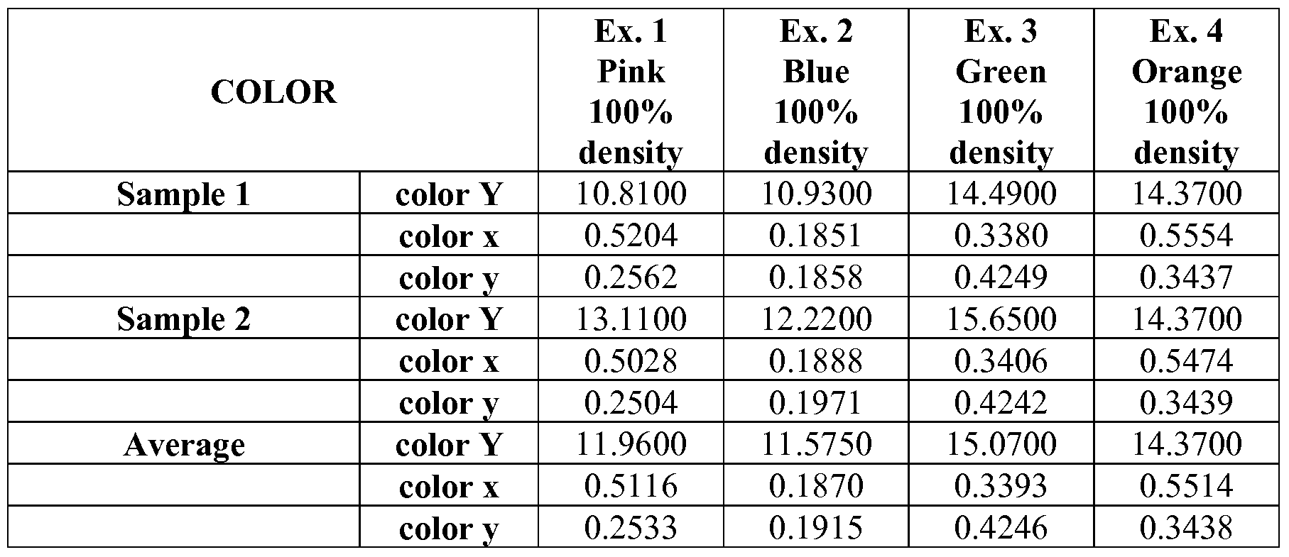
- CIE Color Coordinates were obtained using a colorimeter commercially available from Hunter Associate Laboratory Inc., Reston, VA under the trade designation "Hunterlab ColorFlex.”
- the operating conditions for the "Hunterlab ColorFlex” included a D65 illuminate and a 2 degree observation angle, recording the coordinate for CIE Y, x and y (CIE Commission Internationale d'Eclairage, the International Commission on Illumination).
- CIE 1931 Chromaticity Diagram uses cartesian coordinates to define a color in color space. According to CIE 1931 Chromaticity Diagram, the Y, x, and y coordinates plot the luminance, color saturation, and hue, respectively.
- wash durability testing was performed according to the test method ISO 6330-2A (2000). Wash cycles were 12 min. at 60 0 C (with rinse and spin cycles as specified in ISO 6330-2A) using WASCATOR® washers (Model FOM71MP, Electrolux Laundry Systems Corporation, Copenhagen, Denmark). Dry cycles were performed every fifth wash cycle for 45 min. at 50 0 C using UniDryer dryers (Model UDS-50, UniMac/ Alliance Laundry Systems, Ripon, WI).
- the minimum ANSI/ISEA 107-2004 and EN 471 specification at 0 degrees and 90 degrees orientation angles, at a 0.2 degree observation angle and a -4.0 degree entrance angle is 330 cd/lux/m 2 , as measured according to the above Brightness measurement method.
- EXAMPLES 1-4 RETROREFLECTED ARTICLES COMPRISING AN OPTICAL LAYER BEARING A GRAPHIC
- the graphic was a continuous color, which was applied to the rear surface of the optical layer of a 3MTM SCOTCHLITETM Retrorefiective Series 6260 retroreflective article (available from 3M Company, St. Paul, MN).
- the body portion is formed of a polyvinyl chloride
- the optical layer is formed of UV-reacted bisphenol A epoxy di-acrylate, trimethylolpropane triacrylate, and 1, 6-hexanediol diacrylate.
- the desired graphic i.e., continuous color
- imaging paper available under the trade designation "3MTM 8616" from 3M Company, St. Paul, MN
- 3MTM SCOTCHPRINTTM 2000 electrostatic printer previously available from 3M Company
- 3MTM SCOTCHPRINTTM Dye Sublimation Series 8760/8860 or 8770/8870 transparent dye sublimation toner i.e., previously available from 3M Company; other sublimation dyes that are designed for use with 3MTM SCOTCHPRINTTM printers are currently available from Hilord Chemical Corporation, Hauppauge, NY, including the Hilord SP-2000 Dye
- the printer voltage settings were adjusted to give a graphic on the imaging paper with approximately the following densities: black, 1.35; yellow, 0.67; cyan, 1.35; magenta, 1.35; as measured with a color reflection densitometer (available under the trade designation "X-RITE 404" from X-rite, Inc., Grand Rapids, MI).
- X-RITE 404" available under the trade designation "X-RITE 404" from X-rite, Inc., Grand Rapids, MI.
- Example 1 3MTM SCOTCHPRINTTM Dye Sublimation Series 8772/8872 transparent magenta dye sublimation toner was used to obtain a "pink” color; in Example 2, 3MTM SCOTCHPRINTTM Dye Sublimation Series 8763/8863 transparent cyan dye sublimation toner and 3MTM SCOTCHPRINTTM Dye Sublimation Series 8772/8872 transparent magenta dye sublimation toner were used to obtain a "blue” color; in
- Example 3 3MTM SCOTCHPRINTTM Dye Sublimation Series 8763/8863 transparent cyan dye sublimation toner and 3MTM SCOTCHPRINTTM Dye Sublimation Series 8761/8861 transparent yellow dye sublimation toner were used to obtain a "green" color; and in Example 4, 3MTM SCOTCHPRINTTM Dye Sublimation Series 8772/8872 transparent magenta dye sublimation toner and 3MTM SCOTCHPRINTTM Dye
- Sublimation Series 8761/8861 transparent yellow dye sublimation toner were used to obtain an "orange" color.
- a heat press (available under the trade designation "HIX PRESS N-800” from Hix Corporation, Pittsburgh, KS) was preheated to 350 0 F (177 0 C), with air pressure set to 20 psi (1.4 x 10 5 Pa) and timer set to 30 sec.
- the retroreflective article was sandwiched between silicone paper release liners (available from Mondi Packaging Akrosil LLC, Menasha, WI) with the graphic donor sheet to form a composite, where the sublimation dye side of the graphic donor sheet was in contact with the underside/rear surface of the optical layer.
- silicone paper release liners available from Mondi Packaging Akrosil LLC, Menasha, WI
- step 4 The composite from step 3 was then pressed in the heat press described in step 2 at 350 0 F (177 0 C) and 20 psi (1.4 x 10 5 Pa) for 30 sec. The press was then opened, and the pressed composite was removed from the heat press.
- Example 5 The composite was allowed to cool for 2 min. Then, the graphic donor sheet bearing the sublimation dye was removed from the retroreflective article to form a retroreflective article with an optical layer bearing an infused graphic.
- the brightness (recorded as Coefficient of Retroreflection (R A ; cd/lux/m ) and color (recorded as CIE Color Coordinates) for each of Examples 1-4 were obtained according to the methods described above, the results for which are listed in Tables 1 and 2, respectively. Examples 1-4 were each tested for brightness in duplicates, and averages were calculated for each example. In addition, each of Examples 1-4 was tested for color in duplicates ("Sample 1" and "Sample 2”), and an average for each example was obtained for each CIE color coordinate.
- the graphic was a continuous color, which was applied to the rear surface of the optical layer of a retroreflective article.
- the retroreflective article used in Examples 5-7 and the Control was a 3MTM SCOTCHLITETM Retroreflective Series 6260 retroreflective article (available from 3M Company, St. Paul, MN). In the 3MTM
- the body portion is formed of a polyvinyl chloride
- the optical layer is formed of UV-reacted bisphenol A epoxy di-acrylate, trimethylolpropane triacrylate, and 1, 6-hexanediol diacrylate.
- the rear surface of the optical layer 3MTM SCOTCHLITETM Retroreflective Series 6260 retroreflective article was vapor coated with aluminum (prior to applying the graphic) to form a specularly reflective layer (i.e., a metalized layer) on the rear structured surface of the optical layer.
- Example 5 For each of Examples 5-7, the sublimation process described above with respect to Examples 1-4 was used to obtain the graphic.
- Example 5 3MTM SCOTCHPRINTTM Dye Sublimation Series 8763/8863 transparent cyan dye sublimation toner and 3MTM SCOTCHPRINTTM Dye Sublimation Series 8772/8872 transparent magenta dye sublimation toner were used to obtain a "blue” color.
- Example 6 3MTM SCOTCHPRINTTM Dye Sublimation Series 8763/8863 transparent cyan dye sublimation toner and 3MTM SCOTCHPRINTTM Dye Sublimation Series 8761/8861 transparent yellow dye sublimation toner were used to obtain a "green" color.
- Example 7 3MTM SCOTCHPRINTTM Dye Sublimation Series 8772/8872 transparent magenta dye sublimation toner and 3MTM SCOTCHPRINTTM Dye Sublimation Series 8761/8861 transparent yellow dye sublimation toner were used to obtain an "orange" color.
- An embossing layer i.e., 80 grit aluminum oxide sand paper, available as product number 3461 from 3M Company, St. Paul, MN
- the graphic donor sheet i.e., to the surface not bearing the sublimation dye
- the resulting retroreflective article had a sparkle (or glittering) effect.
- the resulting retroreflective article was metalized, had a sparkle effect, and bore a graphic.
- EXAMPLES 8-13 RETROREFLECTED ARTICLES COMPRISING AN OPTICAL LAYER BEARING A GRAPHIC FORMED BY A ONE-PASS SUBLIMATION PROCESS OR A FIVE-PASS SUBLIMATION PROCESS
- the graphic was a striped pattern, each stripe having a width of 27mm and a length of 230 mm, each stripe being a different color, in the following order: black, yellow, blue, pink, orange, green, purple.
- the graphic was applied to the rear surface of the optical layer of a 3MTM SCOTCHLITETM Retrorefiective Series 6260 retrorefiective article (described above with respect to Examples 1-4, available from 3M Company).
- Example 8 the sublimation process described above with respect to Examples 1-4 was used to obtain the graphic in a one-pass sublimation process.
- the graphic that was printed on the imaging paper to form a graphic donor sheet was the mirror image of the desired graphic (i.e., the mirror image of the desired striped pattern).
- the "black” stripe was formed of 3MTM SCOTCHPRINTTM Dye Sublimation Series 8764/8864 transparent black dye sublimation toner; the "yellow” stripe was formed of 3MTM SCOTCHPRINTTM Dye Sublimation Series 8761/8861 transparent yellow dye sublimation toner; the "blue” stripe was formed of 3MTM SCOTCHPRINTTM Dye Sublimation Series 8763/8863 transparent cyan dye sublimation toner and 3MTM SCOTCHPRINTTM Dye Sublimation Series 8772/8872 transparent magenta dye sublimation toner; the "pink” stripe was formed of 3MTM SCOTCHPRINTTM Dye Sublimation Series 8772/8872 transparent magenta dye sublimation toner; the "orange” stripe was formed of 3MTM SCOTCHPRINTTM Dye Sublimation Series 8772/8872 transparent magenta dye sublimation toner and 3MTM SCOTCHPRINTTM Dye Sublim
- a heat press (available under the trade designation "HIX PRESS N-800” from Hix Corporation, Pittsburgh, KS) was preheated to 300 0 F (149 0 C), with air pressure set to 20 psi (1.4 x 10 5 Pa) and timer set to 50 sec.
- the retroreflective article was sandwiched between silicone paper release liners (available from Mondi Packaging Akrosil LLC, Menasha, WI) with the graphic donor sheet bearing the mirror image of the graphic to form a composite, where the sublimation dye side of the graphic donor sheet was in contact with the underside/rear surface of the optical layer.
- silicone paper release liners available from Mondi Packaging Akrosil LLC, Menasha, WI
- step 4 The composite from step 3 was then pressed in the heat press described in step 2 at 300 0 F (149 0 C) and 20 psi (1.4 x 10 5 Pa) for 50 sec. The press was then opened, and the pressed composite was removed from the heat press. 5. The composite was allowed to cool for 2 min. Then, the graphic donor sheet bearing the sublimation dye was removed from the retroreflective article to form Example 9, a retroreflective article with an optical layer bearing the infused striped pattern.
- Example 10 a retroreflective article with an optical layer bearing the infused striped pattern.
- Examples 11, 12 and 13 were then each formed subsequently, following step 6, using the same graphic donor sheet to obtain the infused striped pattern in the optical layer of each retroreflective article.
- Examples 9-13 as compared to Example 8 and reported in Table 6. Because each of Examples 8-13 were formed of a different sample of the retroreflective article, there is some variability from one example to the next in retroreflectivity. Also, some variability in the brightness and/or color could be due to any variability in the hot pressing step from one example to the next.
- Example 11 the graphic was a checkered pattern consisting of alternating cyan checkers. That is, the cyan checkers formed the imaged portions of the graphic, and spaces between the cyan checkers formed the non-imaged portions of the graphic.
- the graphic used in Example 11 was similar to that of FIGS. 1 and 4 and included 0.75" (1.9 cm) x 0.75" (1.9 cm) squares in a checkerboard pattern with alternating colored (i.e., cyan) and non-colored squares, such that the non-colored squares would maintain the color of the layer onto which the graphic was applied.
- the center-to-center side -by-side distance between colored squares i.e., the center-to-center distance between alternating colored squares
- Each sample was formed by applying the graphic to the underside/rear surface of the optical layer of a 3MTM SCOTCHLITETM Retrorefiective Series 6260 retrorefiective article (described above with respect to Examples 1-4, available from 3M Company), and cutting a strip of the resulting retrorefiective article having dimensions of 2" (5 cm) x 8" (20 cm), with the checkered pattern centered on the 2-inch strip.
- Example 1 1 was tested for brightness before and after 50 wash cycles (i.e., after 50 wash cycles of 5: 1 wash:dry, according to the above-described wash durability test method), the results for which are shown in Table 7, recorded as Coefficient of Retroreflection (R A ; cd/lux/m 2 ) and percent brightness retention ("% Retained”).
- Example 1 1 was tested in two different positions (i.e., "Pl” and "P2") on the strip, and an average was calculated.
- Example 11 was tested for color before and after 50 wash cycles, the results for which are shown in Table 8, recorded as CIE Color Coordinates and Color Shifts.
- Example 1 1 was also visually observed for overall appearance after 15 wash cycles (i.e., 15 wash cycles and 3 dry cycles) and after 50 wash cycles, the results for which are shown in Table 9. TABLE 7. BRIGHTNESS RESULTS BEFORE AND AFTER 50 WASH CYCLES FOR EXAMPLE 11, RECORDED AS COEFFICIENT OF RETROREFLECTION (R A ; cd/lux/m 2 ) AND % RETAINED
Abstract
Description


Claims
Priority Applications (5)
| Application Number | Priority Date | Filing Date | Title |
|---|---|---|---|
| CN200980153674.2A CN102272637B (en) | 2008-12-08 | 2009-11-20 | Prismatic counter-reflective products with figure and preparation method thereof |
| US13/130,833 US8668341B2 (en) | 2008-12-08 | 2009-11-20 | Prismatic retroreflective article bearing a graphic and method of making same |
| JP2011539584A JP2012511177A (en) | 2008-12-08 | 2009-11-20 | Prism-like retroreflective article having figure and method for producing the same |
| EP09836610.7A EP2361396A4 (en) | 2008-12-08 | 2009-11-20 | Prismatic retroreflective article bearing a graphic and method of making same |
| CA2745761A CA2745761A1 (en) | 2008-12-08 | 2009-11-20 | Prismatic retroreflective article bearing a graphic and method of making same |
Applications Claiming Priority (2)
| Application Number | Priority Date | Filing Date | Title |
|---|---|---|---|
| US12068908P | 2008-12-08 | 2008-12-08 | |
| US61/120,689 | 2008-12-08 |
Publications (2)
| Publication Number | Publication Date |
|---|---|
| WO2010077474A2 true WO2010077474A2 (en) | 2010-07-08 |
| WO2010077474A3 WO2010077474A3 (en) | 2010-08-26 |
Family
ID=42310468
Family Applications (1)
| Application Number | Title | Priority Date | Filing Date |
|---|---|---|---|
| PCT/US2009/065228 WO2010077474A2 (en) | 2008-12-08 | 2009-11-20 | Prismatic retroreflective article bearing a graphic and method of making same |
Country Status (8)
| Country | Link |
|---|---|
| US (1) | US8668341B2 (en) |
| EP (1) | EP2361396A4 (en) |
| JP (1) | JP2012511177A (en) |
| KR (1) | KR101610427B1 (en) |
| CN (1) | CN102272637B (en) |
| CA (1) | CA2745761A1 (en) |
| TW (1) | TWI494617B (en) |
| WO (1) | WO2010077474A2 (en) |
Cited By (1)
| Publication number | Priority date | Publication date | Assignee | Title |
|---|---|---|---|---|
| US8506095B2 (en) | 2008-12-08 | 2013-08-13 | 3M Innovative Properties Company | Protective overlay bearing a graphic and retroreflective articles comprising the overlay |
Families Citing this family (9)
| Publication number | Priority date | Publication date | Assignee | Title |
|---|---|---|---|---|
| US10925268B1 (en) * | 2015-03-13 | 2021-02-23 | Ray D. Flasco | Inside corner cubic surface reflector fishing lure |
| WO2016199917A1 (en) * | 2015-06-12 | 2016-12-15 | 日本カーバイド工業株式会社 | Image display device |
| US20170030553A1 (en) * | 2015-07-31 | 2017-02-02 | LED Living Technology, Inc. | Lighting System that Reduces Environmental Light Pollution |
| WO2018151759A1 (en) * | 2017-02-20 | 2018-08-23 | 3M Innovative Properties Company | Optical articles and systems interacting with the same |
| WO2019046403A1 (en) | 2017-08-29 | 2019-03-07 | Avery Dennison Corporation | Retroreflective sheeting for projector-based display system |
| CN108120834B (en) * | 2017-12-08 | 2020-04-24 | 上海君联医疗设备有限公司 | Reagent composition for agglutinating variant cells |
| WO2020240382A1 (en) * | 2019-05-24 | 2020-12-03 | 3M Innovative Properties Company | Radar-optical fusion article and system |
| CN111751557A (en) * | 2020-07-16 | 2020-10-09 | 上海君联医疗设备有限公司 | Sugar chain protein and calcium-histone detection reagent composition and use thereof |
| US20230305203A1 (en) * | 2022-03-25 | 2023-09-28 | Applied Materials, Inc. | Low cost fabrication of optical device using discrete grating module assembly |
Citations (17)
| Publication number | Priority date | Publication date | Assignee | Title |
|---|---|---|---|---|
| US3684348A (en) | 1970-09-29 | 1972-08-15 | Rowland Dev Corp | Retroreflective material |
| US4153412A (en) | 1977-04-25 | 1979-05-08 | Minnesota Mining And Manufacturing Company | Process for printing reflective sheet material |
| US4588258A (en) | 1983-09-12 | 1986-05-13 | Minnesota Mining And Manufacturing Company | Cube-corner retroreflective articles having wide angularity in multiple viewing planes |
| US4775219A (en) | 1986-11-21 | 1988-10-04 | Minnesota Mining & Manufacturing Company | Cube-corner retroreflective articles having tailored divergence profiles |
| US5138488A (en) | 1990-09-10 | 1992-08-11 | Minnesota Mining And Manufacturing Company | Retroreflective material with improved angularity |
| US5387458A (en) | 1990-12-06 | 1995-02-07 | Minnesota Mining And Manufacturing Company | Articles exhibiting durable fluorescence with an ultraviolet screening layer |
| US5450235A (en) | 1993-10-20 | 1995-09-12 | Minnesota Mining And Manufacturing Company | Flexible cube-corner retroreflective sheeting |
| US5605761A (en) | 1994-11-28 | 1997-02-25 | Minnesota Mining And Manufacturing Company | Articles exhibiting durable color containing a polycarbonate, a fluorescent dye and an amine light stabilizer |
| US5614286A (en) | 1993-10-20 | 1997-03-25 | Minnesota Mining And Manufacturing Company | Conformable cube corner retroreflective sheeting |
| US5691846A (en) | 1993-10-20 | 1997-11-25 | Minnesota Mining And Manufacturing Company | Ultra-flexible retroreflective cube corner composite sheetings and methods of manufacture |
| US5698364A (en) | 1993-04-08 | 1997-12-16 | Agfa-Gevaert, N.V. | Dyes and dye receiver elements for thermal dye transfer recording |
| US5814355A (en) | 1996-04-30 | 1998-09-29 | Minnesota Mining And Manufacturing Company | Mold for producing glittering cube-corner retroreflective sheeting |
| US5910812A (en) | 1994-07-21 | 1999-06-08 | Canon Kabushiki Kaisha | Textile printing method and printed textile obtained thereby |
| US6243201B1 (en) | 1999-02-26 | 2001-06-05 | 3M Innovative Properties Company | Retroreflective articles having polymer multilayer reflective coatings |
| US6660390B2 (en) | 2001-03-02 | 2003-12-09 | Chester A. Bacon, Jr. | Printable film and coating composition exhibiting stain resistance |
| US6953624B2 (en) | 2001-03-02 | 2005-10-11 | 3M Innovative Properties Company | Printable film and coating composition exhibiting stain resistance |
| US7195360B2 (en) | 2004-12-28 | 2007-03-27 | 3M Innovative Properties Company | Prismatic retroreflective article and method |
Family Cites Families (57)
| Publication number | Priority date | Publication date | Assignee | Title |
|---|---|---|---|---|
| JP4063472B2 (en) * | 2000-04-10 | 2008-03-19 | 日本カーバイド工業株式会社 | Printed retroreflective sheet |
| US4025159A (en) * | 1976-02-17 | 1977-05-24 | Minnesota Mining And Manufacturing Company | Cellular retroreflective sheeting |
| DE3650027T2 (en) * | 1985-05-07 | 1995-01-26 | Dainippon Printing Co Ltd | Item with transparent hologram. |
| US4664966A (en) * | 1985-11-18 | 1987-05-12 | Minnesota Mining And Manufacturing Company | Enclosed-lens retroreflective sheeting having tough, weather-resistant, transparent cover film |
| US5064272A (en) * | 1985-11-18 | 1991-11-12 | Minnesota Mining And Manufacturing Company | Encapsulated-lens retroreflective sheeting and method of making |
| US4983436A (en) * | 1987-04-15 | 1991-01-08 | Minnesota Mining And Manufacturing Company | Retroreflective sheeting with backing film |
| US5066098A (en) * | 1987-05-15 | 1991-11-19 | Minnesota Mining And Manufacturing Company | Cellular encapsulated-lens high whiteness retroreflective sheeting with flexible cover sheet |
| US5262225A (en) * | 1988-09-02 | 1993-11-16 | Minnesota Mining And Manufacturing Company | Embossable sign construction |
| US5069964A (en) * | 1989-05-23 | 1991-12-03 | Minnesota Mining And Manufacturing Company | Flexible, substrate-insular retroreflective sheeting |
| US5080463A (en) * | 1989-06-21 | 1992-01-14 | Minnesota Mining And Manufacturing Company | Retroreflective security laminates with protective cover sheets |
| US6790578B1 (en) * | 1990-05-15 | 2004-09-14 | 3M Innovative Properties Company | Printing of reflective sheeting |
| US5085918A (en) * | 1990-05-15 | 1992-02-04 | Minnesota Mining And Manufacturing Company | Printed retroreflective sheet |
| US5229882A (en) * | 1990-05-16 | 1993-07-20 | Reflexite Corporation | Colored retroreflective sheeting and method of making same |
| US5213872A (en) * | 1991-04-19 | 1993-05-25 | Stimsonite Corporation | Preprinted retroreflective highway sign and method for making the sign |
| US5169707A (en) * | 1991-05-08 | 1992-12-08 | Minnesota Mining And Manufacturing Company | Retroreflective security laminates with dual level verification |
| US5977263A (en) * | 1992-12-10 | 1999-11-02 | 3M Innovative Properties Company | Thermal transfer compositions, articles and graphic articles made with same |
| US5272562A (en) | 1993-02-05 | 1993-12-21 | Minnesota Mining And Manufacturing Company | Cube-corner retroreflective articles |
| CA2115325A1 (en) | 1993-03-12 | 1994-09-13 | Robert F. Watkins | Retroreflective article clear coats |
| US5344705A (en) * | 1993-05-05 | 1994-09-06 | Minnesota Mining And Manufacturing Company | Retroreflective transfer sheet material |
| US5393590A (en) * | 1993-07-07 | 1995-02-28 | Minnesota Mining And Manufacturing Company | Hot stamping foil |
| US5706133A (en) * | 1995-02-09 | 1998-01-06 | Minnesota Mining And Manufacturing Company | Retroreflective signage articles, kits for producing same, and methods of making signage articles |
| AU7724196A (en) | 1995-11-02 | 1997-05-22 | Minnesota Mining And Manufacturing Company | Microstructured articles with backing and methods of manufacture |
| US5656360A (en) * | 1996-02-16 | 1997-08-12 | Minnesota Mining And Manufacturing Company | Article with holographic and retroreflective features |
| US5770124A (en) * | 1996-04-30 | 1998-06-23 | Minnesota Mining And Manufacturing Company | Method of making glittering cube-corner retroreflective sheeting |
| US6200666B1 (en) * | 1996-07-25 | 2001-03-13 | 3M Innovative Properties Company | Thermal transfer compositions, articles, and graphic articles made with same |
| JP3974959B2 (en) * | 1996-09-30 | 2007-09-12 | スリーエム カンパニー | Method for manufacturing retroreflective information display sheet |
| DE19736083A1 (en) * | 1997-08-20 | 1999-02-25 | Basf Coatings Ag | Multilayer coating system, especially for cars |
| KR100259503B1 (en) | 1997-12-31 | 2001-09-22 | 이종수 | Method for manufacturing a printed steel sheet using a computer |
| US6157486A (en) * | 1998-01-13 | 2000-12-05 | 3M Innovative Properties Company | Retroreflective dichroic reflector |
| US6024455A (en) * | 1998-01-13 | 2000-02-15 | 3M Innovative Properties Company | Reflective article with concealed retroreflective pattern |
| US6054208A (en) * | 1998-01-16 | 2000-04-25 | Avery Dennison Corporation | Film forming mixtures, image bearing films and image bearing retroreflective sheeting |
| US6119751A (en) * | 1998-01-26 | 2000-09-19 | Reflexite Corporation | Apparatus and method for producing retroreflective material having printed patterns thereon |
| US6120636A (en) * | 1998-01-26 | 2000-09-19 | Reflexite Corporation | Apparatus and method for producing retroreflective material having printed patterns thereon |
| JP3477361B2 (en) * | 1998-03-06 | 2003-12-10 | ソニーケミカル株式会社 | Thermal transfer recording medium |
| CN1126961C (en) * | 1998-03-09 | 2003-11-05 | 美国3M公司 | Wide angle image-displaying sheet and system |
| JP4225599B2 (en) | 1998-03-09 | 2009-02-18 | スリーエム カンパニー | Image display sheet and image display system |
| TW467829B (en) * | 1999-05-07 | 2001-12-11 | Chang-San Lin | The manufacturing method of light-reversing reflection material for color images |
| US6677028B1 (en) * | 1999-09-10 | 2004-01-13 | 3M Innovative Properties Company | Retroreflective articles having multilayer films and methods of manufacturing same |
| AU2001286923A1 (en) * | 2000-08-30 | 2002-03-13 | 3M Innovative Properties Company | Graphic base construction, retroreflective graphic article made therefrom and method of making |
| CN1245643C (en) | 2000-10-27 | 2006-03-15 | 林昌三 | Process for preparing optical reflection material of colour pattern |
| US6534128B1 (en) * | 2000-11-09 | 2003-03-18 | 3M Innovative Properties Company | Inks and other compositions incorporating low viscosity, radiation curable, polyester urethane oligomer |
| US6534158B2 (en) * | 2001-02-16 | 2003-03-18 | 3M Innovative Properties Company | Color shifting film with patterned fluorescent and non-fluorescent colorants |
| US6506480B2 (en) * | 2001-02-16 | 2003-01-14 | 3M Innovative Properties Company | Color shifting film with a plurality of fluorescent colorants |
| US6720042B2 (en) * | 2001-04-18 | 2004-04-13 | 3M Innovative Properties Company | Primed substrates comprising radiation cured ink jetted images |
| US20030211299A1 (en) * | 2001-09-27 | 2003-11-13 | 3M Innovative Properties Company | Adhesion-enhancing surfaces for marking materials |
| DE10226932A1 (en) * | 2002-06-17 | 2003-12-24 | Bayer Ag | Radiation-curing coating agents |
| JP2004036161A (en) * | 2002-07-02 | 2004-02-05 | Sekisui Jushi Co Ltd | Recursive reflector |
| JP2004037831A (en) * | 2002-07-03 | 2004-02-05 | Nitto Denko Corp | Retroreflector, polarizing plate with retroreflector, and liquid crystal display device using the same |
| JP4024094B2 (en) * | 2002-07-09 | 2007-12-19 | 日東電工株式会社 | Retroreflecting plate, polarizing plate with retroreflecting plate, and liquid crystal display device using the same |
| US20040029044A1 (en) * | 2002-08-08 | 2004-02-12 | 3M Innovative Properties Company | Photocurable composition |
| JP2004136541A (en) * | 2002-10-17 | 2004-05-13 | Toshiba Corp | Thermal transfer recording medium and printed matter |
| DE20316349U1 (en) * | 2003-10-24 | 2003-12-24 | Fer Fahrzeugelektrik Gmbh | sign |
| US7648744B2 (en) * | 2004-08-06 | 2010-01-19 | 3M Innovative Properties Company | Tamper-indicating printable sheet for securing documents of value and methods of making the same |
| US7611251B2 (en) * | 2006-04-18 | 2009-11-03 | 3M Innovative Properties Company | Retroreflective articles comprising olefinic seal films |
| EP2131218A4 (en) * | 2007-03-30 | 2012-02-29 | Nippon Carbide Kogyo Kk | Retroreflective object |
| US7547105B2 (en) * | 2007-07-16 | 2009-06-16 | 3M Innovative Properties Company | Prismatic retroreflective article with cross-linked image layer and method of making same |
| KR20110098781A (en) | 2008-12-08 | 2011-09-01 | 쓰리엠 이노베이티브 프로퍼티즈 컴파니 | Protective overlay bearing a graphic and retroreflective articles comprising the overlay |
-
2009
- 2009-11-20 WO PCT/US2009/065228 patent/WO2010077474A2/en active Application Filing
- 2009-11-20 KR KR1020117015499A patent/KR101610427B1/en active IP Right Grant
- 2009-11-20 CA CA2745761A patent/CA2745761A1/en not_active Abandoned
- 2009-11-20 CN CN200980153674.2A patent/CN102272637B/en not_active Expired - Fee Related
- 2009-11-20 JP JP2011539584A patent/JP2012511177A/en active Pending
- 2009-11-20 US US13/130,833 patent/US8668341B2/en active Active
- 2009-11-20 EP EP09836610.7A patent/EP2361396A4/en not_active Withdrawn
- 2009-12-03 TW TW098141393A patent/TWI494617B/en not_active IP Right Cessation
Patent Citations (22)
| Publication number | Priority date | Publication date | Assignee | Title |
|---|---|---|---|---|
| US3684348A (en) | 1970-09-29 | 1972-08-15 | Rowland Dev Corp | Retroreflective material |
| US4153412A (en) | 1977-04-25 | 1979-05-08 | Minnesota Mining And Manufacturing Company | Process for printing reflective sheet material |
| US4588258A (en) | 1983-09-12 | 1986-05-13 | Minnesota Mining And Manufacturing Company | Cube-corner retroreflective articles having wide angularity in multiple viewing planes |
| US4775219A (en) | 1986-11-21 | 1988-10-04 | Minnesota Mining & Manufacturing Company | Cube-corner retroreflective articles having tailored divergence profiles |
| US5138488A (en) | 1990-09-10 | 1992-08-11 | Minnesota Mining And Manufacturing Company | Retroreflective material with improved angularity |
| US5387458A (en) | 1990-12-06 | 1995-02-07 | Minnesota Mining And Manufacturing Company | Articles exhibiting durable fluorescence with an ultraviolet screening layer |
| US5698364A (en) | 1993-04-08 | 1997-12-16 | Agfa-Gevaert, N.V. | Dyes and dye receiver elements for thermal dye transfer recording |
| US5988820A (en) | 1993-10-20 | 1999-11-23 | 3M Innovative Properties Company | Flexible cube-corner retroreflective sheeting |
| US20070014011A1 (en) | 1993-10-20 | 2007-01-18 | 3M Innovative Properties Company | Flexible cube-corner retroreflective sheeting |
| US5691846A (en) | 1993-10-20 | 1997-11-25 | Minnesota Mining And Manufacturing Company | Ultra-flexible retroreflective cube corner composite sheetings and methods of manufacture |
| US5450235A (en) | 1993-10-20 | 1995-09-12 | Minnesota Mining And Manufacturing Company | Flexible cube-corner retroreflective sheeting |
| US7185993B2 (en) | 1993-10-20 | 2007-03-06 | 3M Innovative Properties Company | Flexible cube-corner retroflective sheeting |
| US5614286A (en) | 1993-10-20 | 1997-03-25 | Minnesota Mining And Manufacturing Company | Conformable cube corner retroreflective sheeting |
| US6350035B1 (en) | 1993-10-20 | 2002-02-26 | 3M Innovative Properties Company | Flexible cube-corner retroreflective sheeting |
| US5910812A (en) | 1994-07-21 | 1999-06-08 | Canon Kabushiki Kaisha | Textile printing method and printed textile obtained thereby |
| US5605761A (en) | 1994-11-28 | 1997-02-25 | Minnesota Mining And Manufacturing Company | Articles exhibiting durable color containing a polycarbonate, a fluorescent dye and an amine light stabilizer |
| US5814355A (en) | 1996-04-30 | 1998-09-29 | Minnesota Mining And Manufacturing Company | Mold for producing glittering cube-corner retroreflective sheeting |
| US6243201B1 (en) | 1999-02-26 | 2001-06-05 | 3M Innovative Properties Company | Retroreflective articles having polymer multilayer reflective coatings |
| US6723433B2 (en) | 2001-03-02 | 2004-04-20 | 3M Innovative Properties Company | Printable film and coating composition exhibiting stain resistance |
| US6953624B2 (en) | 2001-03-02 | 2005-10-11 | 3M Innovative Properties Company | Printable film and coating composition exhibiting stain resistance |
| US6660390B2 (en) | 2001-03-02 | 2003-12-09 | Chester A. Bacon, Jr. | Printable film and coating composition exhibiting stain resistance |
| US7195360B2 (en) | 2004-12-28 | 2007-03-27 | 3M Innovative Properties Company | Prismatic retroreflective article and method |
Non-Patent Citations (1)
| Title |
|---|
| See also references of EP2361396A4 |
Cited By (1)
| Publication number | Priority date | Publication date | Assignee | Title |
|---|---|---|---|---|
| US8506095B2 (en) | 2008-12-08 | 2013-08-13 | 3M Innovative Properties Company | Protective overlay bearing a graphic and retroreflective articles comprising the overlay |
Also Published As
| Publication number | Publication date |
|---|---|
| EP2361396A4 (en) | 2018-01-24 |
| JP2012511177A (en) | 2012-05-17 |
| CN102272637A (en) | 2011-12-07 |
| TW201030386A (en) | 2010-08-16 |
| WO2010077474A3 (en) | 2010-08-26 |
| KR20110098782A (en) | 2011-09-01 |
| CA2745761A1 (en) | 2010-07-08 |
| EP2361396A2 (en) | 2011-08-31 |
| US20110228393A1 (en) | 2011-09-22 |
| CN102272637B (en) | 2016-01-20 |
| US8668341B2 (en) | 2014-03-11 |
| KR101610427B1 (en) | 2016-04-07 |
| TWI494617B (en) | 2015-08-01 |
Similar Documents
| Publication | Publication Date | Title |
|---|---|---|
| US8668341B2 (en) | Prismatic retroreflective article bearing a graphic and method of making same | |
| US8506095B2 (en) | Protective overlay bearing a graphic and retroreflective articles comprising the overlay | |
| EP2176692B1 (en) | Prismatic retroreflective article with cross-linked image layer and method of making same | |
| US10845514B2 (en) | Retroreflective colored articles | |
| KR101133414B1 (en) | Retroreflective sheeting with controlled cap-y | |
| US20200264352A1 (en) | Exposed-Lens Retroreflective Article Comprising Localized Color Layers | |
| EP1441910A1 (en) | Method of printing retroreflective sheeting and articles | |
| US20200264351A1 (en) | Retroreflective Article Comprising Retroreflective Elements comprising Primary Reflective Layers and Secondary Reflective Layers | |
| MXPA99000884A (en) | Thermal transfer compositions, articles and graphic articles made with same |
Legal Events
| Date | Code | Title | Description |
|---|---|---|---|
| WWE | Wipo information: entry into national phase |
Ref document number: 200980153674.2 Country of ref document: CN |
|
| 121 | Ep: the epo has been informed by wipo that ep was designated in this application |
Ref document number: 09836610 Country of ref document: EP Kind code of ref document: A2 |
|
| WWE | Wipo information: entry into national phase |
Ref document number: 13130833 Country of ref document: US |
|
| WWE | Wipo information: entry into national phase |
Ref document number: 2745761 Country of ref document: CA Ref document number: 2011539584 Country of ref document: JP |
|
| NENP | Non-entry into the national phase |
Ref country code: DE |
|
| WWE | Wipo information: entry into national phase |
Ref document number: 2009836610 Country of ref document: EP |
|
| ENP | Entry into the national phase |
Ref document number: 20117015499 Country of ref document: KR Kind code of ref document: A |