WO2010074203A1 - Pigment for use with photoelectric conversion element, and photoelectric conversion element - Google Patents
Pigment for use with photoelectric conversion element, and photoelectric conversion element Download PDFInfo
- Publication number
- WO2010074203A1 WO2010074203A1 PCT/JP2009/071547 JP2009071547W WO2010074203A1 WO 2010074203 A1 WO2010074203 A1 WO 2010074203A1 JP 2009071547 W JP2009071547 W JP 2009071547W WO 2010074203 A1 WO2010074203 A1 WO 2010074203A1
- Authority
- WO
- WIPO (PCT)
- Prior art keywords
- group
- atom
- formula
- carbon atoms
- independently
- Prior art date
Links
- 0 CCC(CCC1)C2C1CC(C(*C1CC1)C1)*1C2 Chemical compound CCC(CCC1)C2C1CC(C(*C1CC1)C1)*1C2 0.000 description 6
- UCIUAMFTKDIPQS-UHFFFAOYSA-N CCc1cc(Br)cc([F][F]c(c(F)c(CC)c(F)c2F)c2F)c1 Chemical compound CCc1cc(Br)cc([F][F]c(c(F)c(CC)c(F)c2F)c2F)c1 UCIUAMFTKDIPQS-UHFFFAOYSA-N 0.000 description 1
Images


Classifications
-
- H—ELECTRICITY
- H01—ELECTRIC ELEMENTS
- H01G—CAPACITORS; CAPACITORS, RECTIFIERS, DETECTORS, SWITCHING DEVICES OR LIGHT-SENSITIVE DEVICES, OF THE ELECTROLYTIC TYPE
- H01G9/00—Electrolytic capacitors, rectifiers, detectors, switching devices, light-sensitive or temperature-sensitive devices; Processes of their manufacture
- H01G9/20—Light-sensitive devices
- H01G9/2059—Light-sensitive devices comprising an organic dye as the active light absorbing material, e.g. adsorbed on an electrode or dissolved in solution
-
- C—CHEMISTRY; METALLURGY
- C09—DYES; PAINTS; POLISHES; NATURAL RESINS; ADHESIVES; COMPOSITIONS NOT OTHERWISE PROVIDED FOR; APPLICATIONS OF MATERIALS NOT OTHERWISE PROVIDED FOR
- C09B—ORGANIC DYES OR CLOSELY-RELATED COMPOUNDS FOR PRODUCING DYES, e.g. PIGMENTS; MORDANTS; LAKES
- C09B23/00—Methine or polymethine dyes, e.g. cyanine dyes
- C09B23/0008—Methine or polymethine dyes, e.g. cyanine dyes substituted on the polymethine chain
- C09B23/0016—Methine or polymethine dyes, e.g. cyanine dyes substituted on the polymethine chain the substituent being a halogen atom
-
- C—CHEMISTRY; METALLURGY
- C09—DYES; PAINTS; POLISHES; NATURAL RESINS; ADHESIVES; COMPOSITIONS NOT OTHERWISE PROVIDED FOR; APPLICATIONS OF MATERIALS NOT OTHERWISE PROVIDED FOR
- C09B—ORGANIC DYES OR CLOSELY-RELATED COMPOUNDS FOR PRODUCING DYES, e.g. PIGMENTS; MORDANTS; LAKES
- C09B23/00—Methine or polymethine dyes, e.g. cyanine dyes
- C09B23/0008—Methine or polymethine dyes, e.g. cyanine dyes substituted on the polymethine chain
- C09B23/0025—Methine or polymethine dyes, e.g. cyanine dyes substituted on the polymethine chain the substituent being bound through an oxygen atom
-
- C—CHEMISTRY; METALLURGY
- C09—DYES; PAINTS; POLISHES; NATURAL RESINS; ADHESIVES; COMPOSITIONS NOT OTHERWISE PROVIDED FOR; APPLICATIONS OF MATERIALS NOT OTHERWISE PROVIDED FOR
- C09B—ORGANIC DYES OR CLOSELY-RELATED COMPOUNDS FOR PRODUCING DYES, e.g. PIGMENTS; MORDANTS; LAKES
- C09B23/00—Methine or polymethine dyes, e.g. cyanine dyes
- C09B23/0008—Methine or polymethine dyes, e.g. cyanine dyes substituted on the polymethine chain
- C09B23/005—Methine or polymethine dyes, e.g. cyanine dyes substituted on the polymethine chain the substituent being a COOH and/or a functional derivative thereof
- C09B23/0058—Methine or polymethine dyes, e.g. cyanine dyes substituted on the polymethine chain the substituent being a COOH and/or a functional derivative thereof the substituent being CN
-
- C—CHEMISTRY; METALLURGY
- C09—DYES; PAINTS; POLISHES; NATURAL RESINS; ADHESIVES; COMPOSITIONS NOT OTHERWISE PROVIDED FOR; APPLICATIONS OF MATERIALS NOT OTHERWISE PROVIDED FOR
- C09B—ORGANIC DYES OR CLOSELY-RELATED COMPOUNDS FOR PRODUCING DYES, e.g. PIGMENTS; MORDANTS; LAKES
- C09B23/00—Methine or polymethine dyes, e.g. cyanine dyes
- C09B23/0066—Methine or polymethine dyes, e.g. cyanine dyes the polymethine chain being part of a carbocyclic ring,(e.g. benzene, naphtalene, cyclohexene, cyclobutenene-quadratic acid)
-
- C—CHEMISTRY; METALLURGY
- C09—DYES; PAINTS; POLISHES; NATURAL RESINS; ADHESIVES; COMPOSITIONS NOT OTHERWISE PROVIDED FOR; APPLICATIONS OF MATERIALS NOT OTHERWISE PROVIDED FOR
- C09B—ORGANIC DYES OR CLOSELY-RELATED COMPOUNDS FOR PRODUCING DYES, e.g. PIGMENTS; MORDANTS; LAKES
- C09B23/00—Methine or polymethine dyes, e.g. cyanine dyes
- C09B23/02—Methine or polymethine dyes, e.g. cyanine dyes the polymethine chain containing an odd number of >CH- or >C[alkyl]- groups
- C09B23/04—Methine or polymethine dyes, e.g. cyanine dyes the polymethine chain containing an odd number of >CH- or >C[alkyl]- groups one >CH- group, e.g. cyanines, isocyanines, pseudocyanines
-
- C—CHEMISTRY; METALLURGY
- C09—DYES; PAINTS; POLISHES; NATURAL RESINS; ADHESIVES; COMPOSITIONS NOT OTHERWISE PROVIDED FOR; APPLICATIONS OF MATERIALS NOT OTHERWISE PROVIDED FOR
- C09B—ORGANIC DYES OR CLOSELY-RELATED COMPOUNDS FOR PRODUCING DYES, e.g. PIGMENTS; MORDANTS; LAKES
- C09B23/00—Methine or polymethine dyes, e.g. cyanine dyes
- C09B23/02—Methine or polymethine dyes, e.g. cyanine dyes the polymethine chain containing an odd number of >CH- or >C[alkyl]- groups
- C09B23/06—Methine or polymethine dyes, e.g. cyanine dyes the polymethine chain containing an odd number of >CH- or >C[alkyl]- groups three >CH- groups, e.g. carbocyanines
-
- C—CHEMISTRY; METALLURGY
- C09—DYES; PAINTS; POLISHES; NATURAL RESINS; ADHESIVES; COMPOSITIONS NOT OTHERWISE PROVIDED FOR; APPLICATIONS OF MATERIALS NOT OTHERWISE PROVIDED FOR
- C09B—ORGANIC DYES OR CLOSELY-RELATED COMPOUNDS FOR PRODUCING DYES, e.g. PIGMENTS; MORDANTS; LAKES
- C09B23/00—Methine or polymethine dyes, e.g. cyanine dyes
- C09B23/02—Methine or polymethine dyes, e.g. cyanine dyes the polymethine chain containing an odd number of >CH- or >C[alkyl]- groups
- C09B23/08—Methine or polymethine dyes, e.g. cyanine dyes the polymethine chain containing an odd number of >CH- or >C[alkyl]- groups more than three >CH- groups, e.g. polycarbocyanines
- C09B23/083—Methine or polymethine dyes, e.g. cyanine dyes the polymethine chain containing an odd number of >CH- or >C[alkyl]- groups more than three >CH- groups, e.g. polycarbocyanines five >CH- groups
-
- C—CHEMISTRY; METALLURGY
- C09—DYES; PAINTS; POLISHES; NATURAL RESINS; ADHESIVES; COMPOSITIONS NOT OTHERWISE PROVIDED FOR; APPLICATIONS OF MATERIALS NOT OTHERWISE PROVIDED FOR
- C09B—ORGANIC DYES OR CLOSELY-RELATED COMPOUNDS FOR PRODUCING DYES, e.g. PIGMENTS; MORDANTS; LAKES
- C09B23/00—Methine or polymethine dyes, e.g. cyanine dyes
- C09B23/02—Methine or polymethine dyes, e.g. cyanine dyes the polymethine chain containing an odd number of >CH- or >C[alkyl]- groups
- C09B23/08—Methine or polymethine dyes, e.g. cyanine dyes the polymethine chain containing an odd number of >CH- or >C[alkyl]- groups more than three >CH- groups, e.g. polycarbocyanines
- C09B23/086—Methine or polymethine dyes, e.g. cyanine dyes the polymethine chain containing an odd number of >CH- or >C[alkyl]- groups more than three >CH- groups, e.g. polycarbocyanines more than five >CH- groups
-
- H—ELECTRICITY
- H10—SEMICONDUCTOR DEVICES; ELECTRIC SOLID-STATE DEVICES NOT OTHERWISE PROVIDED FOR
- H10K—ORGANIC ELECTRIC SOLID-STATE DEVICES
- H10K85/00—Organic materials used in the body or electrodes of devices covered by this subclass
- H10K85/60—Organic compounds having low molecular weight
- H10K85/649—Aromatic compounds comprising a hetero atom
- H10K85/652—Cyanine dyes
-
- C—CHEMISTRY; METALLURGY
- C09—DYES; PAINTS; POLISHES; NATURAL RESINS; ADHESIVES; COMPOSITIONS NOT OTHERWISE PROVIDED FOR; APPLICATIONS OF MATERIALS NOT OTHERWISE PROVIDED FOR
- C09B—ORGANIC DYES OR CLOSELY-RELATED COMPOUNDS FOR PRODUCING DYES, e.g. PIGMENTS; MORDANTS; LAKES
- C09B23/00—Methine or polymethine dyes, e.g. cyanine dyes
- C09B23/02—Methine or polymethine dyes, e.g. cyanine dyes the polymethine chain containing an odd number of >CH- or >C[alkyl]- groups
- C09B23/08—Methine or polymethine dyes, e.g. cyanine dyes the polymethine chain containing an odd number of >CH- or >C[alkyl]- groups more than three >CH- groups, e.g. polycarbocyanines
-
- C—CHEMISTRY; METALLURGY
- C09—DYES; PAINTS; POLISHES; NATURAL RESINS; ADHESIVES; COMPOSITIONS NOT OTHERWISE PROVIDED FOR; APPLICATIONS OF MATERIALS NOT OTHERWISE PROVIDED FOR
- C09B—ORGANIC DYES OR CLOSELY-RELATED COMPOUNDS FOR PRODUCING DYES, e.g. PIGMENTS; MORDANTS; LAKES
- C09B23/00—Methine or polymethine dyes, e.g. cyanine dyes
- C09B23/10—The polymethine chain containing an even number of >CH- groups
- C09B23/102—The polymethine chain containing an even number of >CH- groups two heterocyclic rings linked carbon-to-carbon
-
- C—CHEMISTRY; METALLURGY
- C09—DYES; PAINTS; POLISHES; NATURAL RESINS; ADHESIVES; COMPOSITIONS NOT OTHERWISE PROVIDED FOR; APPLICATIONS OF MATERIALS NOT OTHERWISE PROVIDED FOR
- C09B—ORGANIC DYES OR CLOSELY-RELATED COMPOUNDS FOR PRODUCING DYES, e.g. PIGMENTS; MORDANTS; LAKES
- C09B23/00—Methine or polymethine dyes, e.g. cyanine dyes
- C09B23/10—The polymethine chain containing an even number of >CH- groups
- C09B23/107—The polymethine chain containing an even number of >CH- groups four >CH- groups
-
- H—ELECTRICITY
- H01—ELECTRIC ELEMENTS
- H01G—CAPACITORS; CAPACITORS, RECTIFIERS, DETECTORS, SWITCHING DEVICES OR LIGHT-SENSITIVE DEVICES, OF THE ELECTROLYTIC TYPE
- H01G9/00—Electrolytic capacitors, rectifiers, detectors, switching devices, light-sensitive or temperature-sensitive devices; Processes of their manufacture
- H01G9/20—Light-sensitive devices
- H01G9/2027—Light-sensitive devices comprising an oxide semiconductor electrode
- H01G9/2031—Light-sensitive devices comprising an oxide semiconductor electrode comprising titanium oxide, e.g. TiO2
-
- Y—GENERAL TAGGING OF NEW TECHNOLOGICAL DEVELOPMENTS; GENERAL TAGGING OF CROSS-SECTIONAL TECHNOLOGIES SPANNING OVER SEVERAL SECTIONS OF THE IPC; TECHNICAL SUBJECTS COVERED BY FORMER USPC CROSS-REFERENCE ART COLLECTIONS [XRACs] AND DIGESTS
- Y02—TECHNOLOGIES OR APPLICATIONS FOR MITIGATION OR ADAPTATION AGAINST CLIMATE CHANGE
- Y02E—REDUCTION OF GREENHOUSE GAS [GHG] EMISSIONS, RELATED TO ENERGY GENERATION, TRANSMISSION OR DISTRIBUTION
- Y02E10/00—Energy generation through renewable energy sources
- Y02E10/50—Photovoltaic [PV] energy
- Y02E10/542—Dye sensitized solar cells
Definitions
- the present invention relates to a photoelectric conversion element using a dye and a dye suitably used for the photoelectric conversion element.
- dyes are widely used in various technical fields.
- photoelectric conversion elements such as solar cells
- they are used for dye-sensitized photoelectric conversion elements using a dye having a photosensitizing action.
- This dye-sensitized photoelectric conversion element can be expected to have a theoretically high efficiency, and is considered to be very advantageous in terms of cost compared to a conventional photoelectric conversion element using a silicon semiconductor.
- the dye-sensitized photoelectric conversion element has an electrode having an oxide semiconductor as a dye carrier.
- the dye is absorbed and excited by the incident light, and the excited dye injects electrons into the carrier to perform photoelectric conversion.
- Ruthenium complex dyes and organic dyes are known as dyes used in dye-sensitized photoelectric conversion elements. In particular, since organic dyes are relatively stable and can be easily synthesized, various studies have been made.
- a cyanine dye having a structure in which an indolenine skeleton is bonded to both ends of a methine chain skeleton and a carboxylic acid group as an anchor group for adsorbing to an oxide semiconductor electrode is used.
- the technique used is known (for example, refer to Patent Documents 1 and 2).
- such cyanine dyes are also used as dyes for optical filters and optical recording materials (for example, see Patent Document 3).
- the present invention has been made in view of such problems, and an object thereof is to provide a photoelectric conversion element dye and a photoelectric conversion element capable of improving the conversion efficiency.
- the photoelectric conversion element dye of the present invention has a cyanine structure represented by the formula (1).
- the photoelectric conversion element of the present invention includes an electrode having a dye and a carrier supporting the dye, and the dye includes a cyanine compound having a cyanine structure represented by Formula (1).
- R1 and R2 are each independently a hydroxyl group, a nitro group, a cyano group or a halogen atom, or an alkyl group, an alkoxy group, an aryl group, an arylalkyl group or a derivative thereof, and a and b are each independently 0-4.
- R3 to R6 are each independently a hydrogen atom, a hydroxyl group, a nitro group, a cyano group or a halogen atom, or an alkyl group, an alkoxy group, an aryl group, an arylalkyl group or a derivative thereof, and among R3 and R4, And at least one of R5 and R6 may be eliminated to form a double bond, or may be linked to form a ring structure, and X1 is —C (R7) ( A group represented by R8) —, a group represented by —N (R9) —, a sulfur atom, an oxygen atom, a selenium atom or a tellurium atom.
- X2 is a group represented by —C (R10) (R11) —, a group represented by —N (R12) —, a sulfur atom, an oxygen atom, a selenium atom or a tellurium atom
- R7, R8, R10 and R11 is each independently an alkyl group, an alkoxy group, an aryl group, an arylalkyl group or a derivative thereof except a hydrogen atom, a group represented by the formula (2), or a group corresponding to the group represented by the formula (2)
- R9 and R12 are each independently a hydrogen atom, a hydroxyl group, a nitro group, a cyano group or a halogen atom, or an alkyl group, an alkoxy group, an aryl group, an arylalkyl group, or a derivative thereof
- Y1 and Y2 are each independently Are an anchor group, an alkyl group, an alkoxy group, an aryl group, an ary
- the “derivative” described in the formula (1) means a group in which a hydrogen atom in a substituent is substituted with another atom or atomic group, and an atom introduced instead of a hydrogen atom is
- the atomic group introduced instead of a hydrogen atom include, for example, a hydroxyl group, a nitro group, a cyano group, an acyl group, a saturated cyclic hydrocarbon group, an unsaturated cyclic hydrocarbon group, an aromatic group, and the like.
- An aromatic group or a heterocyclic group is exemplified.
- “may be eliminated to form a double bond” means, for example, that either one of R3 and R4 and one of R5 and R6 shown in formula (1) is By desorption, the bond between the carbon atom into which R3 and R4 are introduced and the carbon atom into which R5 and R6 are introduced may be a double bond. The same applies to the bond between the carbon atom into which R3 and R4 in formula (3) described later are introduced and the carbon atom into which R5 and R6 are introduced.
- the “anchor group” refers to a group having a chemical or electrostatic affinity and binding ability for a support for supporting a compound.
- R21 to R23 are each independently A hydrogen atom, a hydroxyl group, a nitro group, a cyano group, a halogen atom, an alkyl group having 1 to 4 carbon atoms or a halogenated alkyl group having 1 to 4 carbon atoms
- R24 is a hydrogen atom, a hydroxyl group, a nitro group, A cyano group, a halogen atom, an alkyl group having 1 to 4 carbon atoms, an alkoxy group having 1 to 4 carbon atoms, a halogenated alkyl
- halogenation of the halogenated alkyl group and the halogenated alkoxy group described in the formula (2) means that part or all of the hydrogen atoms contained in the alkyl group and the alkoxy group are one kind of halogen elements or A group substituted with two or more atoms.
- the cyanine structure represented by the formula (1) is a 5-membered ring skeleton as at least one of the heterocyclic skeletons introduced at both ends of the methine chain skeleton (Q). And a phenanthrene skeleton condensed with.
- the light absorption peak wavelength is shifted to the longer wavelength side due to the spread of ⁇ conjugation as a whole molecule, but the peak intensity is secured. In this state, the light absorption peak becomes broad.
- At least one of Y1 and Y2 bonded to the nitrogen atom contained in the 5-membered ring portion in the heterocyclic skeleton contributes to the bond with the carrier. Function as. Thereby, when light is absorbed and excited while being carried on the carrier, electrons are efficiently injected into the carrier.
- the compound having the cyanine structure represented by the formula (1) when irradiated with light in a state of being supported on the support, instead of the phenanthrene skeleton, Compared with a cyanine compound containing a benzene skeleton or a naphthalene skeleton, it absorbs light in a wide wavelength range and is excited, and efficiently injects electrons into the carrier. Therefore, in the photoelectric conversion element using the cyanine compound represented by the formula (1) as the pigment, the ratio of the amount of electrons injected into the carrier with respect to the irradiated light amount increases, and the efficiency of photoelectric conversion is improved.
- the cyanine compound represented by the formula (1) may be a compound having a structure represented by the formula (3).
- cyanine compounds compounds having a structure in which a heterocyclic skeleton is bonded to both ends of the methine chain skeleton
- carbon atoms and heteroatoms constituting the methine chain skeleton and heterocyclic skeleton are arranged on a plane. It tends to be a structure (structure with high flatness).
- the planarity of the molecular structure is increased, molecules are likely to associate with each other to form an association such as a dimer, and the dye that has formed the association is less likely to contribute to photoelectric conversion.
- R7 and R8 in the formula (3) are on the upper surface side and the lower surface side with respect to the plane including the methine chain skeleton and the heterocyclic skeleton. Since they are arranged so as to protrude into both spaces, the whole molecule has low planarity and is difficult to associate.
- the photoelectric conversion element using the compound represented by the formula (3) as the dye the ratio of aggregates that hardly contribute to photoelectric conversion in the entire dye supported on the support decreases, so that the efficiency of photoelectric conversion is improved. Become good.
- R1 and R2 are each independently a hydroxyl group, a nitro group, a cyano group or a halogen atom, or an alkyl group, an alkoxy group, an aryl group, an arylalkyl group or a derivative thereof, and a and b are each independently 0-4.
- R3 to R6 are each independently a hydrogen atom, a hydroxyl group, a nitro group, a cyano group or a halogen atom, or an alkyl group, an alkoxy group, an aryl group, an arylalkyl group or a derivative thereof, and among R3 and R4, And at least one of R5 and R6 may be eliminated to form a double bond, or may be linked to form a ring structure, and X2 is —C (R10) ( R11) — group, —N (R12) — group, sulfur atom, oxygen atom, selenium atom or tellurium source R7, R8, R10 and R11 are each independently an alkyl group, an alkoxy group, excluding a hydrogen atom or a group represented by the above formula (2), or a group corresponding to the group represented by the formula (2), An aryl group, an arylalkyl group or a derivative thereof, each R12 is independently a hydrogen atom, a
- the cyanine compound represented by the formula (1) may be a compound having a structure represented by the formula (4).
- R10 and R11 together with R7 and R8 in the formula (4) are both on the upper surface side and the lower surface side with respect to the plane including the methine chain skeleton and the heterocyclic skeleton. Since they are arranged so as to protrude into the space, the whole molecule has lower planarity and is less likely to associate.
- the proportion of aggregates that hardly contribute to photoelectric conversion in the entire dye supported on the support decreases, so that the efficiency of photoelectric conversion is improved. Become good.
- R1 and R2 are each independently a hydroxyl group, a nitro group, a cyano group or a halogen atom, or an alkyl group, an alkoxy group, an aryl group, an arylalkyl group or a derivative thereof, and a and b are each independently 0-4.
- R7, R8, R10 and R11 are each independently a hydrogen atom, an alkyl group or an alkoxy group other than those represented by the group represented by the formula (2) or the group represented by the formula (2).
- a ring is a benzene ring, naphthalene ring, phenanthrene ring or a derivative thereof
- Y1 and Y2 are each independently an anchor group, an alkyl group, an alkoxy group, an aryl group, an aryl group, an arylalkyl group, or a derivative thereof.
- One is an anchor group .Q is .An p-is a linkage group that has a methine chain having 1 to 7 carbon atoms as a skeleton is a p-valent anion, p is 1 or 2, q is the charge Is a neutral coefficient.
- the cyanine compound represented by the formula (1) may be a compound having a structure represented by the formula (5).
- the compound represented by the formula (5) since both of the heterocyclic skeletons introduced at both ends of the methine chain skeleton include the phenanthrene skeleton, electrons are more efficiently injected into the support.
- the planarity of the molecule as a whole becomes lower and it becomes more difficult to associate.
- the ratio of the aggregate that hardly contributes to the photoelectric conversion in the entire dye supported on the support decreases, and the amount of light irradiated
- the efficiency of photoelectric conversion is further improved.
- R1, R2, R13 and R14 are each independently a hydroxyl group, a nitro group, a cyano group or a halogen atom, or an alkyl group, an alkoxy group, an aryl group, an arylalkyl group or a derivative thereof; R is an integer of 0 to 4.
- R7, R8, R10 and R11 are each independently an alkyl other than a hydrogen atom or a group represented by the above formula (2) or a group represented by the formula (2)
- Y1 and Y2 are each independently an anchor group, or an alkyl group, an alkoxy group, an aryl group, an arylalkyl group, or a derivative thereof; At least one of Y2 is an anchor group, Q is a methine chain having 1 to 7 carbon atoms.
- A is .An p-linking group and a p-valent anion, p is 1 or 2, q is a coefficient to maintain neutral electric charge.
- the photoelectric conversion element dye and photoelectric conversion element of the present invention at least one of R7, R8, R10, and R11 shown in Formula (1) or Formula (3) to Formula (5) is as described above.
- the group shown in Formula (2) is preferable.
- the sterically bulky group represented by the formula (2) greatly protrudes into at least one of the upper surface side and the lower surface side with respect to the plane including the methine chain skeleton and the heterocyclic skeleton in the cyanine structure. Therefore, the entire molecule has a large steric size that is less likely to associate.
- dye since the ratio of the aggregate which is hard to contribute to the photoelectric conversion in the whole pigment
- the anchor group represented by formula (1) or formula (3) to formula (5) is —CH 2 —CH 2 —C ( ⁇ O) —.
- a group represented by OH or a group represented by —CH 2 —CH 2 —C ( ⁇ O) —O 2 — is preferred.
- both Y1 and Y2 shown in the formula (1) or the formulas (3) to (5) are anchor groups.
- Q shown in Formula (1) or Formula (3) to Formula (5) is preferably a linking group in which a cyano group is introduced into the methine chain skeleton. Thereby, the efficiency of photoelectric conversion further improves.
- the support preferably contains zinc oxide (ZnO).
- ZnO zinc oxide
- the dye for photoelectric conversion elements of the present invention since it has the cyanine structure represented by the formula (1), it is excited by absorbing light in a wide wavelength range as compared with a dye having no structure. The electron injection efficiency for the supported carrier is improved. Therefore, according to the photoelectric conversion element of the present invention, since the dye supported on the support contains the compound having the cyanine structure represented by the formula (1), the conversion efficiency can be improved. In this case, if at least one of R7, R8, R10 and R11 shown in the formula (1) is a group shown in the above formula (2), the formation of aggregates is further suppressed, so that the conversion is further performed. Efficiency can be improved. Further, when both Y1 and Y2 in the formula (1) are anchor groups, or Q in the formula (1) is a linking group in which a cyano group is introduced into the methine chain skeleton, higher conversion efficiency is obtained. be able to.
- the conversion efficiency can be further improved if the carrier carrying the dye contains zinc oxide.
- a dye according to an embodiment of the present invention is used for a dye-sensitized photoelectric conversion element (for a photoelectric conversion element) and has a cyanine structure represented by the formula (1) (hereinafter, a formula (Referred to as the cyanine compound shown in (1)).
- the cyanine compound represented by the formula (1) has, for example, an adsorptive property (bonding property) to a support including a metal oxide semiconductor material, and is excited by absorbing light to the electron. It is a compound that can be injected.
- the cyanine compound has a resonance structure between the methine chain skeleton (Q) and two nitrogen atoms in the heterocyclic skeleton introduced at both ends thereof.
- the formula (1) represents a structural formula in which a nitrogen atom (nitrogen atom introduced with Y1) contained in a heterocyclic skeleton having a phenanthrene ring is positively charged (N + ).
- the cyanine compound shown in (1) is not limited to the structure represented by this structural formula.
- the nitrogen atom bonded to Y2 in formula (1) may be in a positively charged state.
- a bond between carbon atoms in the methine chain skeleton and Y1 are introduced so as to form a double bond between the nitrogen atom bonded to Y2 and the carbon atom adjacent to the nitrogen atom on the Q side.
- a resonance structure represented by a structural formula in which double bonds and single bonds alternate in the bond between the formed nitrogen atom and the carbon atom adjacent to the Q side of the nitrogen atom may be employed.
- R1 and R2 are each independently a hydroxyl group, a nitro group, a cyano group or a halogen atom, or an alkyl group, an alkoxy group, an aryl group, an arylalkyl group or a derivative thereof, and a and b are each independently 0-4.
- R3 to R6 are each independently a hydrogen atom, a hydroxyl group, a nitro group, a cyano group or a halogen atom, or an alkyl group, an alkoxy group, an aryl group, an arylalkyl group or a derivative thereof, and among R3 and R4, And at least one of R5 and R6 may be eliminated to form a double bond, or may be linked to form a ring structure, and X1 is —C (R7) ( A group represented by R8) —, a group represented by —N (R9) —, a sulfur atom, an oxygen atom, a selenium atom or a tellurium atom.
- X2 is a group represented by —C (R10) (R11) —, a group represented by —N (R12) —, a sulfur atom, an oxygen atom, a selenium atom or a tellurium atom
- R7, R8, R10 and R11 is each independently an alkyl group, an alkoxy group, an aryl group, an arylalkyl group or a derivative thereof except a hydrogen atom, a group represented by the formula (2), or a group corresponding to the group represented by the formula (2)
- R9 and R12 are each independently a hydrogen atom, a hydroxyl group, a nitro group, a cyano group or a halogen atom, or an alkyl group, an alkoxy group, an aryl group, an arylalkyl group, or a derivative thereof
- Y1 and Y2 are each independently Are an anchor group, an alkyl group, an alkoxy group, an aryl group, an ary
- R21 to R23 are each independently A hydrogen atom, a hydroxyl group, a nitro group, a cyano group, a halogen atom, an alkyl group having 1 to 4 carbon atoms or a halogenated alkyl group having 1 to 4 carbon atoms
- R24 is a hydrogen atom, a hydroxyl group, a nitro group, A cyano group, a halogen atom, an alkyl group having 1 to 4 carbon atoms, an alkoxy group having 1 to 4 carbon atoms, a halogenated alkyl
- the cyanine compound represented by the formula (1) includes a heterocyclic skeleton including a 5-membered ring skeleton introduced at both ends of the methine chain skeleton (Q), Y1 bonded to a nitrogen atom contained in the 5-membered ring skeleton, and And an anchor group introduced as at least one of Y2.
- At least one of both heterocyclic skeletons introduced at both ends of the methine chain skeleton includes a phenanthrene skeleton condensed with a five-membered ring skeleton.
- the cyanine compound represented by the formula (1) includes a methine chain skeleton having 1 to 7 carbon atoms, so that the light absorption peak wavelength of the compound is between the ultraviolet light region and the near infrared light region. Become. This light absorption peak wavelength shifts to a longer wavelength side than the light absorption peak wavelength of a cyanine compound containing a benzene skeleton or a naphthalene skeleton instead of the phenanthrene skeleton due to the spread of ⁇ conjugation as a whole molecule due to the inclusion of the phenanthrene skeleton. To do.
- the light absorption peak of the cyanine compound represented by the formula (1) is broadened in a state in which the peak intensity is secured as compared with the light absorption peak of the cyanine compound having no phenanthrene skeleton. That is, by including the phenanthrene skeleton, the width of the light absorption wavelength region of the cyanine compound represented by the formula (1) is wider than the width of the light absorption wavelength region of the cyanine compound having no phenanthrene skeleton.
- an anchor group that contributes to the bond with the carrier is introduced into at least one of the nitrogen atoms of both the heterocyclic skeletons, it is excited by absorbing light while being carried on the carrier. Electrons are efficiently injected into the carrier.
- the cyanine compound represented by the formula (1) when the cyanine compound represented by the formula (1) is irradiated with light including components in the ultraviolet light region, visible light region, and near infrared light region in a state of being supported on the carrier, a wide wavelength of the light is emitted. The light component in the region is absorbed and excited, and electrons are efficiently injected into the carrier. Therefore, in the photoelectric conversion element using the cyanine compound represented by the formula (1), the ratio of the amount of electrons injected into the carrier with respect to the irradiated light amount is increased, and the conversion efficiency is improved. In addition, if the cyanine compound shown in Formula (1) has the structure shown in Formula (1), even if it is the enantiomer or diastereomer, the same effect is acquired.
- R1 and R2 described in the formula (1) represent a group excluding a hydrogen atom (hydrogen group) introduced into the phenanthrene skeleton, and the kind thereof may be any of the monovalent groups described above.
- the numbers (a and b in the formula (1)) are arbitrary as long as they are integers between 0 and 4. When the sum of a and b is 2 or more and two of R1 and R2 are adjacent to each other, two adjacent groups may be bonded to form a ring structure. From the viewpoint of ease, R1 and R2 are preferably introduced as a monovalent group without forming a ring structure.
- R1 and R2 are halogen atoms
- examples of the halogen atom include a fluorine atom, a chlorine atom, a bromine atom, and an iodine atom.
- R1 and R2 are an alkyl group, an alkoxy group, an aryl group, an arylalkyl group or a derivative thereof
- the number of carbon atoms constituting the skeleton is also arbitrary.
- examples of the alkyl group, alkoxy group, aryl group, arylalkyl group or derivatives thereof include the following. That is, examples of the alkyl group and derivatives thereof include methyl group, ethyl group, propyl group, isopropyl group, butyl group, second butyl group, third butyl group, isobutyl group, amyl group, isoamyl group, hexyl group, and cyclohexyl.
- Heterocyclic groups acyl groups such as acetyl groups or acidic groups such as carboxylic acid groups Etc. introduced group.
- Alkoxy groups and derivatives thereof include methoxy group, ethoxy group, propyloxy group, isopropyloxy group, butyloxy group, second butyloxy group, third butyloxy group, isobutyloxy group, amyloxy group, isoamyloxy group, third amyloxy group Hexyloxy group, cyclohexyloxy group, cyclohexylmethyloxy group, cyclohexylethyloxy group, heptyloxy group, isoheptyloxy group, third heptyloxy group, n-octyloxy group, isooctyloxy group, third octyloxy group An alkoxy group having 1 to 20 carbon atoms such as 2-ethylhexyloxy group, nonyloxy group, isononyl
- Groups in which an aromatic group such as a phenyl group, a heterocyclic group such as a thiophene group, an acyl group such as an acetyl group, or an acidic group such as a carboxylic acid group is introduced.
- Examples of the aryl group and derivatives thereof include 6 to 6 carbon atoms such as phenyl group, naphthyl group, anthracen-1-yl group, tetracenyl group, pentacenyl group, chrysenyl group, triphenylenyl group, pyrenyl group, picenyl group, and perylenyl group.
- the arylalkyl group and derivatives thereof include carbon atoms such as benzyl group, phenethyl group, 2-phenylpropane group, diphenylmethyl group, triphenylmethyl group, styryl group, cinnamyl group, naphthylmethyl group or biphenylmethyl group.
- arylalkyl groups 7-30 arylalkyl groups, halogenated groups thereof, alkyl groups such as methyl groups, alkoxy groups such as methoxy groups, aromatic ring groups such as phenyl groups, thiophene groups, etc.
- alkyl groups such as methyl groups
- alkoxy groups such as methoxy groups
- aromatic ring groups such as phenyl groups, thiophene groups, etc.
- a heterocyclic group an acyl group such as an acetyl group, or a group introduced with an acidic group such as a carboxylic acid group.
- R3 to R6 described in the formula (1) are groups introduced into the carbon atom contained in the 5-membered heterocyclic ring on the side having no phenanthrene skeleton in the formula (1). Any one is optional.
- Specific examples of R3 to R6 include, in addition to a hydrogen atom (hydrogen group), for example, the same monovalent groups introduced as R1 and R2.
- at least one of R3 to R6 is preferably an alkyl group having 1 to 25 carbon atoms, an alkoxy group having 1 to 20 carbon atoms, an aryl group, an arylalkyl group, or a derivative thereof. .
- cyanine compounds compounds having a structure in which a heterocyclic skeleton is bonded to both ends of the methine chain skeleton
- a structure in which carbon atoms and heteroatoms constituting the methine chain skeleton and the heterocyclic skeleton are arranged in a plane It tends to be a structure with high so-called flatness.
- planarity of the molecular structure is high, molecules are associated with each other so as to overlap each other, and an aggregate such as a dimer is easily formed.
- the dye that forms the aggregate is less likely to contribute to photoelectric conversion because the efficiency of electron injection is low even if it is supported on the support.
- R3 to R6 introduced into the carbon atoms included in the heterocyclic skeleton are on the upper surface side and the lower surface with respect to the plane including the methine chain skeleton and the heterocyclic skeleton unless a double bond is formed between the carbon atoms. It arrange
- At least one of R3 to R6 is sterically bulky such as an alkyl group having 6 to 25 carbon atoms, an alkoxy group having 5 to 20 carbon atoms, an aryl group, an arylalkyl group, or a derivative thereof.
- a high group is preferred. This is because the formation of aggregates is further suppressed and a high effect is obtained.
- At least one of R3 and R4 and at least one of R5 and R6 may be eliminated to form a double bond, or each Thus, a ring structure may be formed.
- one of R3 and R4 and one of R5 and R6 are eliminated to form a double bond, and the other of R3 and R4 that is not eliminated and the other of R5 and R6 are They may be linked to form a ring structure.
- Examples of the ring structure formed by linking in this way include, for example, a benzene ring, naphthalene ring, anthracene ring, phenanthrene ring, cyclohexane ring, cyclobutane ring, cyclopentane ring, cyclohexene ring, cycloheptane ring, piperidine ring, and piperazine.
- the ring structure may be a structure obtained by further condensing the plurality of ring structures described above, or may be a derivative thereof having one or more substituents.
- the ring structure formed by linking at R3 to R6 is preferably a benzene ring, a naphthalene ring, a phenanthrene ring or a derivative thereof. This is because the electron injection efficiency into the carrier is likely to be higher than in the case where other ring structures are formed.
- X1 and X2 described in Formula (1) are arbitrary as long as they are any of the above-described divalent groups.
- R7, R8, R10 and R11 are Any monovalent group described above may be used.
- Specific examples of R7, R8, R10 and R11 include, for example, a hydrogen atom, an alkyl group and an alkoxy group described in R1 to R6 described above except those corresponding to the group shown in the formula (2) described later. , An aryl group, an arylalkyl group or a derivative thereof.
- R9 and R12 include R1 to R6 described above. And the same groups as those introduced as above.
- R7, R8, R10 and R11 in the formula (1) may be a group shown in the formula (2), and the group shown in the formula (2) is a group having the structure described above. Is optional.
- Examples of the halogen atom described in formula (2) include the same halogen atoms as described in formula (1).
- Examples of the group represented by the formula (2) include a vinyl group (—CH ⁇ CH 2 ), an allyl group (—CH 2 —CH ⁇ CH 2 ), a 1-propenyl group (—CH ⁇ CH—CH 3 ), Isopropenyl group (—C (CH 3 ) ⁇ CH 2 ), 1-butenyl group (—CH ⁇ CH—CH 2 —CH 3 ), 2-butenyl group (—CH 2 —CH ⁇ CH—CH 3 ), 2 —Methylallyl group (—CH 2 —C (CH 3 ) ⁇ CH 2 ), 2-pentenyl group (—CH 2 —CH ⁇ CH—CH 2 —CH 3 ), ethynyl group (—C ⁇ CH), 2-propynyl Group (—CH 2 —C ⁇ CH), 1-propynyl group (—C ⁇ C—CH 3 ), 2-butynyl group (—CH 2 —C ⁇ C—CH 3 ) or 3-butynyl group (—CH 2 -
- Examples of the group shown in Formula (2) when R21 and R24 or R22 and R23 are linked to form a ring structure include, for example, a cyclohexenyl group, a phenethyl group, and Formula (2-1).
- X1 in the formula (1) is preferably a group represented by —C (R7) (R8) — or —N (R9) —, and represented by —C (R7) (R8) —. More preferably, it is a group.
- X2 in the formula (1) is preferably a group represented by —C (R10) (R11) — or —N (R12) —, and in particular, —C (R10) (R11 )-Is more preferable. This is because the planarity of the molecule as a whole is lowered, so that the formation of aggregates is suppressed and the conversion efficiency is easily improved.
- R7 to R12 be a sterically bulky group as described above so that the steric size of the entire molecule is increased. This is because the flatness becomes lower and higher effects can be obtained.
- X1 and X2 are preferably groups represented by —C (R7) (R8) — and —C (R10) (R11) —, respectively.
- R7, R8, R10 and R11 are arranged so as to project into both the upper surface side and the lower surface side of the plane including the methine chain skeleton and the heterocyclic skeleton. The flatness is lowered and the molecules are less likely to associate with each other, thereby contributing to an improvement in conversion efficiency.
- R7, R8, R10 and R11 is sterically bulky, among them, an alkyl group having 6 to 25 carbon atoms or a group represented by the formula (2) Preferably there is. This is because the planarity of the whole molecule is further lowered, and a high association inhibitory action can be obtained.
- the sterically bulky group is preferably introduced as R7 and R8, or R10 and R11. Rather than being introduced as R7 and R10, or R8 and R11, it is arranged so as to overhang so as to occupy both the upper surface side and the lower surface side of the plane including the methine chain skeleton and the heterocyclic skeleton. Therefore, the planarity of the whole molecule is further lowered, and a three-dimensional molecular structure is easily obtained.
- the number of sterically bulky groups introduced as R7, R8, R10 or R11 is preferably three rather than two and four more than three. Further preferred.
- Y1 and Y2 described in the formula (1) are arbitrary as long as they are monovalent groups as described above. Since at least one of Y1 and Y2 is an anchor group that imparts chemical or electrostatic affinity and binding ability to the support to the compound, it is supported on the support and is efficient with respect to the support. Electrons are often injected. Especially, it is preferable that both Y1 and Y2 are anchor groups. This is because peeling from the carrier is further suppressed, and electron injection efficiency to the carrier is further increased. Examples of the anchor group include a group represented by the formula (6). If R30 demonstrated in Formula (6) is a (e + 1) valent saturated hydrocarbon group, the structure and the number of carbon atoms are arbitrary.
- Z1 is a functional group for binding or adsorbing to the carrier, and the number (e) is arbitrary as long as it is contained in the formula (6) at least one.
- Z1 include a carboxylic acid group, a sulfonic acid group, a phosphoric acid group, a carboxylic acid ion group, a sulfonic acid ion group, and a phosphoric acid ion group.
- the number of carbon atoms of R30 in formula (6) is 1 or more and 4 or less, and Z1 is preferably a carboxylic acid group or a carboxylic acid ion group.
- R30 is a divalent divalent having 2 carbon atoms.
- the carboxylic acid group and the carboxylate ion group are functional groups having a high binding ability to the support and high electron withdrawing ability, the electron injection efficiency can be obtained by combining with R30 in the above-mentioned range of the number of carbon atoms. This is because the fixability becomes higher.
- the anchor group may be included in the cyanine structure shown in the formula (1) as long as it is introduced as at least one of Y1 and Y2 in the formula (1).
- R30 is an (e + 1) -valent saturated hydrocarbon group
- Z1 is an acidic group or a group obtained by ionizing the acidic group
- e is an integer of 1 or more.
- Q described in formula (1) is arbitrary as long as it is a linking group having a methine chain (monomethine to heptamethine) having 1 to 7 carbon atoms as a skeleton, and may further have a substituent.
- the substituents may be bonded to each other to form a ring structure.
- the reason why the number of carbon atoms in the methine chain is 1 or more and 7 or less is that light absorption in a wide range from ultraviolet light to near infrared light becomes good.
- Q preferably has one or more cyano groups introduced to the carbon atoms constituting the methine chain skeleton. Thereby, the fixability to the carrier and the electron injection efficiency are increased, which contributes to the improvement of the conversion efficiency.
- the coupling group represented by Formula (7) is mentioned, for example.
- R40 to R42 are each independently a hydrogen atom or a substituent, and when having a plurality of R40s and a plurality of R41s, R40s or R41s may be the same as or different from each other. Adjacent ones of R40 to R42 may be bonded to form a cyclic structure, and m is an integer of 0 to 3.
- the linking group represented by the formula (7) represents an odd number of 1 to 7 carbon atoms constituting the methine chain skeleton.
- the substituent is introduced at the carbon atom that is the center of the methine chain skeleton. Is preferred. This is because the balance of charge bias as a whole molecule is good, and the electron injection efficiency to the carrier is likely to increase. In this case, the substituent is more preferably a cyano group. This is because the charge balance is improved and the conversion efficiency is easily improved.
- Specific examples of the linking group represented by the formula (7) include linking groups represented by the formulas (7-1) to (7-10).
- the linking groups represented by formulas (7-1) to (7-4) are specific examples of linking groups having no ring structure, and are represented by formulas (7-5) to (7-10).
- the linking group is a specific example in the case of having a ring structure.
- examples of the linking group in which a substituent is introduced into the carbon atom that is the center of the methine chain skeleton include a substituent introduced as R43 in the formulas (7-1) to (7-10). Etc.
- R43 to R49 are each independently a hydrogen atom, a hydroxyl group, a halogen atom, a cyano group, an aryl group having 6 to 30 carbon atoms, a diphenylamino group, an alkyl group having 1 to 8 carbon atoms, or one or more carbon atoms. 8 or less alkoxy groups.
- An p ⁇ described in the formula (1) is a counter anion for maintaining the charge of the whole cyanine compound shown in the formula (1) to be neutral, and is arbitrary as long as it is a monovalent or divalent anion.
- Inorganic anions such as chlorate ion or thiocyanate ion, benzenesulfonate ion, toluenesulfonate i
- q demonstrated in Formula (1) is a coefficient which keeps an electric charge neutral as the whole cyanine compound shown in Formula (1), and may be 0.
- one of Y1 and Y2 in formula (1) has a monovalent ionic group, and forms a salt in the molecule to become a so-called internal salt. .
- the cyanine compound represented by the formula (1) is a compound having a structure represented by the formula (3) in which X1 is a divalent group represented by —C (R7) (R8) — (hereinafter, represented by the formula (3) It is preferable to be a compound shown in the above). This is because, as described above, formation of aggregates is suppressed, which contributes to improvement in conversion efficiency.
- R1 to R8, X2, R10 to R12, Y1, Y2 and (An p ⁇ ) q described in formula (3) are R1 to R8, X2, R10 to R12, Y1, Y2 in formula (1). And the same as (An p- ) q .
- R1 and R2 are each independently a hydroxyl group, a nitro group, a cyano group or a halogen atom, or an alkyl group, an alkoxy group, an aryl group, an arylalkyl group or a derivative thereof, and a and b are each independently 0-4.
- R3 to R6 are each independently a hydrogen atom, a hydroxyl group, a nitro group, a cyano group or a halogen atom, or an alkyl group, an alkoxy group, an aryl group, an arylalkyl group or a derivative thereof, and among R3 and R4, And at least one of R5 and R6 may be eliminated to form a double bond, or may be linked to form a ring structure, and X2 is —C (R10) ( R11) — group, —N (R12) — group, sulfur atom, oxygen atom, selenium atom or tellurium source R7, R8, R10 and R11 are each independently an alkyl group, an alkoxy group, excluding a hydrogen atom or a group represented by the above formula (2), or a group corresponding to the group represented by the formula (2), An aryl group, an arylalkyl group or a derivative thereof, each R12 is independently a hydrogen atom, a
- R7, R8, R10 and R11 is preferably a sterically bulky group, and is represented by formula (2).
- a group is preferred.
- X2 is preferably a group represented by -C (R10) (R11)-for the same reason as described above.
- a double bond is formed by elimination of one of R3 and R4 and one of R5 and R6, and among R3 and R4 which are not eliminated.
- a ring structure is preferably formed by linking the other of R5 and the other of R5 and R6. This is because the electron injection efficiency with respect to the carrier becomes better, and a higher effect can be obtained.
- Q is preferably a linking group having a cyano group introduced into the methine chain skeleton. Both are for the same reason as above.
- the compound represented by the formula (3) is a compound represented by the formula (4) in which X2 is a group represented by —C (R10) (R11) — and a ring structure is formed by elimination and connection of R3 to R6. It is preferable that it is a compound (henceforth the compound shown to Formula (4)) which has a structure represented by these.
- X2 is a group represented by —C (R10) (R11) —
- the aggregate inhibitory action is enhanced, and a ring structure is formed by the elimination and linking of R3 to R6, so that This is because the electron injection efficiency is increased.
- R1, R2, R7, R8, R10, R11, Y1, Y2 and (An p ⁇ ) q described in formula (4) are R1, R2, R7, R8, R10, R11 in formula (3). , Y1, Y2 and (An p- ) q are the same.
- R1 and R2 are each independently a hydroxyl group, a nitro group, a cyano group or a halogen atom, or an alkyl group, an alkoxy group, an aryl group, an arylalkyl group or a derivative thereof, and a and b are each independently 0-4.
- R7, R8, R10 and R11 are each independently a hydrogen atom, an alkyl group or an alkoxy group other than those represented by the group represented by the formula (2) or the group represented by the formula (2).
- a ring is a benzene ring, naphthalene ring, phenanthrene ring or a derivative thereof
- Y1 and Y2 are each independently an anchor group, an alkyl group, an alkoxy group, an aryl group, an aryl group, an arylalkyl group, or a derivative thereof.
- One is an anchor group .Q is .An p-is a linkage group that has a methine chain having 1 to 7 carbon atoms as a skeleton is a p-valent anion, p is 1 or 2, q is the charge Is a neutral coefficient.
- Ring A described in formula (4) is optional as long as it has a benzene ring, naphthalene ring or phenanthrene ring skeleton, and may have one or more substituents.
- ring A is a naphthalene ring or a phenanthrene ring
- the position at which the ring is condensed with a 5-membered heterocyclic ring is also arbitrary.
- the substituent introduced into ring A is arbitrary, for example, an alkyl group such as a methyl group, an ethyl group or a butyl group, an alkoxy group such as a methoxy group or an ethoxy group, an aryl group such as a phenyl group, or a phenyl group such as a benzyl group Examples thereof include alkyl groups or derivatives thereof.
- R7, R8, R10 and R11 is preferably a sterically bulky group. It is preferable that it is group represented by.
- Q is preferably a linking group having a cyano group introduced into the methine chain skeleton. Both are for the same reason as above.
- a compound having a structure represented by the formula (5) in which the ring A is a phenanthrene ring or a derivative thereof (hereinafter referred to as a compound represented by the formula (5)) is preferable.
- a compound represented by the formula (5) a compound having a structure represented by the formula (5) in which the ring A is a phenanthrene ring or a derivative thereof.
- R1, R2, R7, R8, R10, R11, Y1, Y2 and (An p ⁇ ) q described in the formula (5) are R1, R2, R7, R8, R10, R11 in the formula (4).
- Y1, Y2 and (An p ⁇ ) q are the same.
- R13 and R14 demonstrated in Formula (5) the thing similar to R1 and R2 is mentioned.
- R1, R2, R13 and R14 are each independently a hydroxyl group, a nitro group, a cyano group or a halogen atom, or an alkyl group, an alkoxy group, an aryl group, an arylalkyl group or a derivative thereof; R is an integer of 0 to 4.
- R7, R8, R10 and R11 are each independently an alkyl other than a hydrogen atom or a group represented by the above formula (2) or a group represented by the formula (2)
- Y1 and Y2 are each independently an anchor group, or an alkyl group, an alkoxy group, an aryl group, an arylalkyl group, or a derivative thereof; At least one of Y2 is an anchor group, Q is a methine chain having 1 to 7 carbon atoms.
- A is .An p-linking group and a p-valent anion, p is 1 or 2, q is a coefficient to maintain neutral electric charge.
- R7, R8, R10 and R11 is preferably a sterically bulky group, and is represented by the formula (2). It is preferably a group.
- Q is preferably a linking group having a cyano group introduced into the methine chain skeleton. Both are for the same reason as above.
- Examples of the cyanine compound represented by the formula (1) including the compounds represented by the above formulas (3) to (5) include compounds having a structural part represented by the formulas (8) to (283). It is done. Note that the structural parts shown in the formulas (8) to (283) represent a part (cation part) that does not contain An p- in the formula (1). In these structures, for example, the above-described 1 Any anionic or divalent anion can be combined, and the same applies to other anions. In these structural parts, for example, an acidic group can be ionized to form an internal salt.
- the compound having the cyanine structure represented by the formula (1) is not limited to the compound including the structural portion represented by the formulas (8) to (283). The same applies to the formulas (5) to (5).
- the cyanine compound represented by the above formula (1) can be synthesized, for example, by the following two methods.
- a compound having 1 carbon atom in the methine chain skeleton contained in Q in the formula (1) is synthesized.
- a group that becomes Y1 or Y2 is introduced to the nitrogen atom in the 5-membered ring skeleton included in the heterocyclic skeleton in the formula (1).
- a compound having a heterocyclic skeleton represented by the formula (284), a compound represented by the formula (285), and as necessary A quaternary ammonium salt represented by the formula (286) is synthesized by mixing and reacting with a predetermined amount of anion which becomes An p- .
- the compound having a heterocyclic skeleton represented by the formula (284) includes a skeleton portion that is bonded to both ends of the methine chain skeleton (Q) in the formula (1).
- the compound represented by the formula (285) includes a portion which is introduced into a nitrogen atom contained in the 5-membered ring portion in the formula (286) and becomes Y1 when R51 is eliminated.
- the formula (I) the synthesis of a portion containing a phenanthrene skeleton in the heterocyclic skeleton bonded to both ends of the methine chain skeleton is shown, but the other heterocyclic skeleton portion can be synthesized in the same manner.
- R1, R2, a, b, X1 and Y1 are the same as R1, R2, a, b, X1 and Y1 described in formula (1), and R50 is a hydrogen atom or a monovalent group.
- p- is a p-valent anion
- p is 1 or 2
- q is a coefficient that keeps the charge neutral in the compound of formula (286).
- the quaternary ammonium salt represented by the formula (286) and the quaternary ammonium salt represented by the formula (287) having a leaving group (R52). are reacted in the presence of a base.
- a cyanine compound (formula (288)) having 1 carbon atom in the methine chain skeleton contained in Q in formula (1) is synthesized as the final product.
- the quaternary ammonium salt having the leaving group R52 represented by the formula (287) can be synthesized, for example, in the same manner as the quaternary ammonium salt represented by the formula (286).
- R1 ⁇ R6, a, b , X1, X2 and Y1, Y2 are the same as R1 ⁇ R6, a, b, X1, X2 and Y1, Y2 explained in Formula (1) .
- R50 is a hydrogen atom Or a monovalent substituent
- R52 is a group represented by —S—R100 or a leaving group such as —CH ⁇ N—OH
- R100 is an alkyl group such as a methyl group.
- a compound in which the number of carbon atoms in the methine chain skeleton contained in Q in formula (1) is larger than 1 is synthesized.
- a quaternary ammonium salt represented by the formula (286) is synthesized in the same manner as the procedure represented by the chemical reaction formula of the formula (I).
- the quaternary ammonium salt shown in the formula (286) and the compound represented by the formula (289) as a bridging agent are mixed and reacted.
- Examples of the compound represented by the formula (289) used as the bridging agent in the chemical reaction formula of the formula (III) include compounds represented by the formulas (289-1) to (289-4), Examples of other bridging agents include compounds represented by formulas (293) to (295).
- R1, R2, a, b, X1 and Y1 are the same as R1, R2, a, b, X1 and Y1 described in formula (1).
- An p- is a p-valent anion; p is 1 or 2, and q is a coefficient for keeping the charge neutral in the compounds of the formulas (286) and (290)
- R50 and R53 are hydrogen atoms or monovalent substituents
- Q1 is a linking group having a methine chain having 1 to 5 carbon atoms as a skeleton.
- R1 ⁇ R6, a, b , X1, X2 and Y1, Y2 are the same as R1 ⁇ R6, a, b, X1, X2 and Y1, Y2 explained in Formula (1) .
- p is 1 or 2
- q is a coefficient for maintaining a neutral charge in the compounds of the formulas (290) to (292)
- R50, R53 and R54 is a hydrogen atom or a monovalent substituent
- Q1 is a linking group having a methine chain having 1 to 5 carbon atoms as a skeleton.
- the cyanine represented by the formula (290) using the quaternary ammonium salt shown in the formula (286) or the like In order to synthesize the intermediate, it was synthesized in two steps. However, if the final product contains a heterocyclic skeleton bonded to both ends of the methine chain and has the same structure, for example, as shown in the chemical reaction formula of the formula (V), the reaction is performed in one step. The final product (formula (296)) may be obtained. In this case, the quaternary ammonium salt represented by the formula (286) and the bridging agent represented by the formula (289) are reacted in the presence of a base and acetic anhydride ((CH 3 CO) 2 O).
- R1, R2, a, b, X1 and Y1 are the same as R1, R2, a, b, X1 and Y1 described in formula (1).
- An p- is a p-valent anion; p is 1 or 2, and q is a coefficient for maintaining a neutral charge in the compounds of the formulas (286) and (296)
- R50 and R53 are hydrogen atoms or monovalent substituents
- Q1 is a linking group having a methine chain having 1 to 5 carbon atoms as a skeleton.
- the dye for photoelectric conversion elements has the cyanine structure represented by the formula (1), the dye does not have the structure (for example, a cyanine compound containing a benzene skeleton or a naphthalene skeleton instead of a phenanthrene skeleton). ) Is absorbed by absorbing light in a wide wavelength region from the ultraviolet light region to the near infrared light region. In addition, electrons can be efficiently injected into the carrier while being carried on the carrier. Therefore, when used for a photoelectric conversion element, the amount of electrons injected from the dye to the carrier increases with respect to the amount of light irradiated, IPCE (Incident Photonsto Current Current conversion Efficiency) is improved, and conversion efficiency can be improved.
- IPCE Incident Photonsto Current Current conversion Efficiency
- IPCE represents the ratio of photocurrent converted to the number of electrons with respect to the number of photons irradiated in the photoelectric conversion element
- IPCE (%) Isc ⁇ 1240 / ⁇ ⁇ 1 / ⁇ (formula Where Isc is a short circuit current, ⁇ is a wavelength, and ⁇ is an incident light intensity.
- the cyanine structure shown in Formula (1) may be the structure shown in Formula (3), the structure shown in Formula (4), or the structure shown in Formula (5).
- Good since planarity falls as a whole molecule
- the cyanine structure shown in Formula (1) is the structure shown in Formula (5), both heterocyclic skeletons introduced at both ends of the methine chain skeleton contain phenanthrene skeletons. In contrast, electrons are injected more efficiently, and a higher effect is easily obtained.
- R7, R8, R10 and R11 shown in Formula (1) or Formula (3) to Formula (5) is a group shown in Formula (2) above, the entire molecule Therefore, the conversion efficiency can be further improved when used in a photoelectric conversion element.
- both Y1 and Y2 shown in the formula (1) or the formulas (3) to (5) are anchor groups, it is difficult to peel off from the carrier, so that when used in a photoelectric conversion element, the element The amount of electrons injected into the carrier increases with respect to the amount of light absorbed as a whole, and higher conversion efficiency can be obtained.
- Q in the formula (1) or formulas (3) to (5) is a linking group in which a cyano group is introduced into the methine chain skeleton, and when used in a photoelectric conversion element, the IV characteristics ( The shape factor (FF; FillFactor) of current-voltage characteristics can be improved, and high conversion efficiency can be obtained.
- the shape factor (FF; FillFactor) of current-voltage characteristics can be improved, and high conversion efficiency can be obtained.
- FIG. 1 schematically shows a cross-sectional configuration of a photoelectric conversion element
- FIG. 2 shows an extracted and enlarged main part of the photoelectric conversion element shown in FIG.
- the photoelectric conversion element shown in FIGS. 1 and 2 is a main part of a so-called dye-sensitized solar cell.
- the working electrode 10 and the counter electrode 20 are disposed to face each other with the electrolyte-containing layer 30 interposed therebetween, and at least one of the working electrode 10 and the counter electrode 20 is an electrode having optical transparency. It is.
- the working electrode 10 is, for example, supported on a conductive substrate 11, a metal oxide semiconductor layer 12 provided on one surface thereof (surface on the counter electrode 20 side), and the metal oxide semiconductor layer 12 as a carrier. Pigment 13.
- the working electrode 10 functions as a negative electrode for the external circuit.
- the conductive substrate 11 is obtained by providing a conductive layer 11B on the surface of an insulating substrate 11A.
- Examples of the material of the substrate 11A include insulating materials such as glass, plastic, and transparent polymer film.
- the transparent polymer film include tetraacetyl cellulose (TAC), polyethylene terephthalate (PET), polyethylene naphthalate (PEN), syndiotactic polystyrene (SPS), polyphenylene sulfide (PPS), polycarbonate (PC), polyarylate ( PAR), polysulfone (PSF), polyester sulfone (PES), polyetherimide (PEI), cyclic polyolefin or brominated phenoxy.
- TAC tetraacetyl cellulose
- PET polyethylene terephthalate
- PEN polyethylene naphthalate
- SPS syndiotactic polystyrene
- PPS polyphenylene sulfide
- PC polycarbonate
- PAR polyarylate
- PAR polysulfone
- PET polyester sulfone
- PEI polyether
- Examples of the conductive layer 11B include a conductive metal oxide thin film including indium oxide, tin oxide, indium-tin composite oxide (ITO), or tin oxide doped with fluorine (FTO: F—SnO 2 ). , A metal thin film containing gold (Au), silver (Ag), platinum (Pt), or the like, or a conductive polymer or the like.
- the conductive substrate 11 may be configured to have a single-layer structure with, for example, a conductive material.
- a conductive material examples include indium oxide, tin oxide, Examples thereof include conductive metal oxides such as indium-tin composite oxide or tin oxide doped with fluorine, metals such as gold, silver or platinum, and conductive polymers.
- the metal oxide semiconductor layer 12 is a carrier that supports the dye 13, and has, for example, a porous structure as shown in FIG.
- the metal oxide semiconductor layer 12 is formed of a dense layer 12A and a porous layer 12B.
- the dense layer 12A is formed at the interface with the conductive substrate 11, is preferably dense and has few voids, and more preferably is a film.
- the porous layer 12B is preferably formed on the surface in contact with the electrolyte-containing layer 30, has a large space and a large surface area, and more preferably has a structure in which porous fine particles are attached.
- the metal oxide semiconductor layer 12 may be formed to have, for example, a film-like single layer structure.
- Examples of the material (metal oxide semiconductor material) included in the metal oxide semiconductor layer 12 include titanium oxide, zinc oxide, tin oxide, niobium oxide, indium oxide, zirconium oxide, tantalum oxide, vanadium oxide, yttrium oxide, and oxide. Examples thereof include aluminum and magnesium oxide. Among these, zinc oxide is preferable as the metal oxide semiconductor material. This is because high conversion efficiency can be obtained. These metal oxide semiconductor materials may be used alone or in combination of two or more (mixed, mixed crystal, solid solution, etc.), for example, zinc oxide and A combination of tin oxide, titanium oxide and niobium oxide can also be used.
- Examples of the method for forming the metal oxide semiconductor layer 12 having a porous structure include an electrolytic deposition method and a firing method.
- the metal oxide semiconductor layer 12 is formed by electrolytic deposition, the fine particles are deposited on the conductive layer 11B of the conductive substrate 11 in the electrolytic bath liquid containing the fine particles of the metal oxide semiconductor material and the metal.
- An oxide semiconductor material is deposited.
- a dispersion liquid metal oxide slurry
- an electrolytic deposition method is preferable. This is because high conversion efficiency can be obtained and a plastic material or polymer film material having low heat resistance can be used as the substrate 11A, so that a highly flexible photoelectric conversion element can be manufactured.
- the dye 13 is, for example, adsorbed to the metal oxide semiconductor layer 12, and is capable of injecting electrons into the metal oxide semiconductor layer 12 by absorbing light and being excited. Contains more than one type of pigment.
- dye 13 contains the 1 type (s) or 2 or more types of the cyanine compounds shown to said Formula (1) as this pigment
- the dye 13 may contain other dyes in addition to the cyanine compound represented by the formula (1).
- the other dye is preferably a dye having an anchor group that can be chemically bonded to the metal oxide semiconductor layer 12.
- other dyes include eosin Y, dibromofluorescein, fluorescein, rhodamine B, pyrogallol, dichlorofluorescein, erythrosine B (erythrocin is a registered trademark), fluorescin, mercurochrome, cyanine dye, merocyanine disazo dye, trisazo dye, Anthraquinone dyes, polycyclic quinone dyes, indigo dyes, diphenylmethane dyes, trimethylmethane dyes, quinoline dyes, benzophenone dyes, naphthoquinone dyes, perylene dyes, fluorenone dyes, squarylium dyes, azurenium dyes And organic dyes such as perinone dyes
- organometallic complex compounds For example, an ionic coordinate bond formed by a nitrogen anion and a metal cation in an aromatic heterocycle, a nitrogen atom or Organometallic complex compounds having both nonionic coordination bonds formed between chalcogen atoms and metal cations, ionic coordination bonds formed by oxygen anions or sulfur anions and metal cations, and nitrogen And organometallic complex compounds having both nonionic coordination bonds formed between an atom or chalcogen atom and a metal cation.
- organometallic complex compounds For example, an ionic coordinate bond formed by a nitrogen anion and a metal cation in an aromatic heterocycle, a nitrogen atom or Organometallic complex compounds having both nonionic coordination bonds formed between chalcogen atoms and metal cations, ionic coordination bonds formed by oxygen anions or sulfur anions and metal cations, and nitrogen And organometallic complex compounds having both nonionic coordination bonds formed between an atom or chalcogen atom and a metal cation.
- metal phthalocyanine dyes such as copper phthalocyanine and titanyl phthalocyanine, metal naphthalocyanine dyes, metal porphyrin dyes, bipyridyl ruthenium complexes, terpyridyl ruthenium complexes, phenanthroline ruthenium complexes, bicinchonirate ruthenium complexes, and azo ruthenium complexes
- a ruthenium complex such as a quinolinol ruthenium complex can be used.
- dye 13 may contain the 1 type (s) or 2 or more types of additive other than the above-mentioned pigment
- the additive include an association inhibitor that suppresses association of the dye in the dye 13, and specifically includes a cholic acid compound represented by the formula (297). These may be used alone or in combination of two or more.
- R60 represents a group bonded to any of the carbon atoms constituting the steroid skeleton in the formula, and includes a hydroxyl group, a halogen group, an alkyl group, an alkoxy group, an aryl group, a heterocyclic group, an acyl group, an acyloxy group, and an oxycarbonyl group.
- R61 is an alkyl group having an acidic group
- t is an integer of 1 to 5.
- the bond between the carbon atoms constituting the steroid skeleton in the formula may be a single bond or a double bond.
- the counter electrode 20 is, for example, a conductive substrate 21 provided with a conductive layer 22 and functions as a positive electrode for an external circuit.
- Examples of the material of the conductive substrate 21 include the same materials as those of the conductive substrate 11 of the working electrode 10.
- the conductive layer 22 includes one type or two or more types of conductive material and a binder as necessary.
- Examples of the conductive material used for the conductive layer 22 include platinum, gold, silver, copper (Cu), rhodium (Rh), ruthenium (Ru), aluminum (Al), magnesium (Mg), and indium (In). Examples include metals, carbon (C), and conductive polymers.
- binder used for the conductive layer 22 examples include acrylic resin, polyester resin, phenol resin, epoxy resin, cellulose, melamine resin, fluoroelastomer, and polyimide resin.
- the counter electrode 20 may have a single layer structure of the conductive layer 22, for example.
- the electrolyte-containing layer 30 includes, for example, a redox electrolyte having a redox pair.
- the redox electrolyte include I ⁇ / I 3 ⁇ system, Br ⁇ / Br 3 ⁇ system, and quinone / hydroquinone system.
- a combination of a halide salt and a simple substance of halogen such as a combination of an iodide salt and simple iodine or a combination of a bromide salt and bromine.
- halide salts include cesium halides, quaternary alkyl ammonium halides, imidazolium halides, thiazolium halides, oxazolium halides, quinolinium halides and pyridinium halides.
- these iodide salts include, for example, cesium iodide, tetraethylammonium iodide, tetrapropylammonium iodide, tetrabutylammonium iodide, tetrapentylammonium iodide, tetrahexylammonium iodide, tetra Quaternary alkylammonium iodides such as heptylammonium iodide or trimethylphenylammonium iodide, and imidazolium iodides such as 3-methylimidazolium iodide or 1-propyl-2,3-dimethylimidazolium iodide 3-ethyl-2-methyl-2-thiazolium iodide, 3-ethyl-5- (2-hydroxyethyl) -4-methylthiazolium iodide or 3-ethyl-5
- bromide salts include quaternary alkyl ammonium bromides.
- combinations of halide salts and simple halogens combinations of at least one of the above-described iodide salts and simple iodine are preferable.
- the redox electrolyte may be, for example, a combination of an ionic liquid and a halogen simple substance.
- the above-described halide salt and the like may be further included.
- the ionic liquid include those that can be used in batteries, solar cells, and the like. For example, “Inorg. Chem” 1996, 35, p 1168 to 1178, “Electrochemistry” 2002, 2, p 130 to 136; And those disclosed in JP-A No. 507334 or JP-A-8-259543.
- the ionic liquid a salt having a melting point lower than room temperature (25 ° C.), or a salt that has a melting point higher than room temperature and is liquefied at room temperature by dissolving with another molten salt is preferable.
- this ionic liquid include the following anions and cations.
- Examples of the cation of the ionic liquid include ammonium, imidazolium, oxazolium, thiazolium, oxadiazolium, triazolium, pyrrolidinium, pyridinium, piperidinium, pyrazolium, pyrimidinium, pyrazinium, triazinium, phosphonium, sulfonium, carbazolium, indolium, or those And derivatives thereof. These may be used alone or as a mixture of plural kinds. Specific examples include 1-methyl-3-propylimidazolium, 1-butyl-3-methylimidazolium, 1,2-dimethyl-3-propylimidazolium, and 1-ethyl-3-methylimidazolium. .
- anion of the ionic liquid examples include metal chlorides such as AlCl 4 ⁇ or Al 2 Cl 7 — , PF 6 ⁇ , BF 4 ⁇ , CF 3 SO 3 ⁇ , N (CF 3 SO 2 ) 2 ⁇ , F ( HF) n - or CF 3 COO - or a fluorine-containing substance such as ion, NO 3 -, CH 3 COO -, C 6 H 11 COO -, CH 3 OSO 3 -, CH 3 OSO 2 -, CH 3 SO 3 -
- Non-fluorine compound ions such as CH 3 SO 2 ⁇ , (CH 3 O) 2 PO 2 ⁇ , N (CN) 2 ⁇ or SCN ⁇ , and halide ions such as iodide ions or bromide ions. These may be used alone or as a mixture of plural kinds. Among these, iodide ions are preferable as the anions of the ionic liquid.
- the electrolyte-containing layer 30 may be a liquid electrolyte (electrolytic solution) obtained by dissolving the above-described redox electrolyte in a solvent, or a solid polymer electrolyte in which the electrolytic solution is held in a polymer substance. May be.
- a quasi-solid (paste-like) electrolyte containing a mixture of an electrolytic solution and a particulate carbon material such as carbon black may be used. Note that in a quasi-solid electrolyte containing a carbon material, since the carbon material has a function of catalyzing a redox reaction, the electrolyte may not contain a single halogen.
- Such a redox electrolyte may contain any one kind or two or more kinds of organic solvents that dissolve the above-described halide salts, ionic liquids, and the like.
- organic solvent include electrochemically inert solvents such as acetonitrile, propionitrile, butyronitrile, methoxyacetonitrile, 3-methoxypropionitrile, valeronitrile, dimethyl carbonate, ethyl methyl carbonate, ethylene carbonate.
- this photoelectric conversion element when light (sunlight or ultraviolet light, visible light, or near infrared light equivalent to sunlight) is applied to the dye 13 carried on the working electrode 10, the light is absorbed.
- the excited dye 13 injects electrons into the metal oxide semiconductor layer 12. After the electrons move to the adjacent conductive layer 11B, they reach the counter electrode 20 via an external circuit.
- the electrolyte-containing layer 30 the electrolyte is oxidized so that the oxidized dye 13 is returned (reduced) to the ground state as the electrons move.
- This oxidized electrolyte is reduced by receiving the above-described electrons. In this way, the movement of electrons between the working electrode 10 and the counter electrode 20 and the accompanying oxidation-reduction reaction in the electrolyte-containing layer 30 are repeated. Thereby, continuous movement of electrons occurs, and photoelectric conversion is constantly performed.
- This photoelectric conversion element can be manufactured as follows, for example.
- the working electrode 10 is produced.
- the metal oxide semiconductor layer 12 having a porous structure is formed on the surface of the conductive substrate 11 on which the conductive layer 11B is formed by electrolytic deposition or firing.
- electrolytic deposition for example, an electrolytic bath containing a metal salt to be a metal oxide semiconductor material is set to a predetermined temperature while bubbling with oxygen or air, and the conductive substrate 11 is placed therein. Immerse and apply a constant voltage between the counter electrode. Thereby, a metal oxide semiconductor material is deposited on the conductive layer 11B so as to have a porous structure.
- the counter electrode may be appropriately moved in the electrolytic bath.
- a metal oxide slurry prepared by dispersing a powder of a metal oxide semiconductor material in a dispersion medium is applied to the conductive substrate 11 and dried, followed by firing. Have a porous structure. Subsequently, a dye solution in which the dye 13 containing the cyanine compound represented by the above formula (1) is dissolved in an organic solvent is prepared. By immersing the conductive substrate 11 on which the metal oxide semiconductor layer 12 is formed in this dye solution, the metal oxide semiconductor layer 12 carries the dye 13.
- the counter electrode 20 is produced by forming the conductive layer 22 on one surface of the conductive substrate 21.
- the conductive layer 22 is formed, for example, by sputtering a conductive material.
- a spacer such as a sealant so that the surface of the working electrode 10 carrying the dye 13 and the surface of the counter electrode 20 on which the conductive layer 22 is formed are opposed to each other while maintaining a predetermined distance.
- the whole is sealed except for the electrolyte inlet.
- the electrolyte containing layer 30 is formed by injecting an electrolyte between the working electrode 10 and the counter electrode 20 and then sealing the injection port. Thereby, the photoelectric conversion element shown in FIGS. 1 and 2 is completed.
- the dye 13 contains the cyanine compound represented by the formula (1), compared to the case where the cyanine compound having no structure represented by the formula (1) is used, Since the ratio of the amount of electrons injected from the dye 13 into the metal oxide semiconductor layer 12 is increased, the conversion efficiency can be improved. In this case, in particular, if the metal oxide semiconductor layer 12 includes zinc oxide, the conversion efficiency is improved as compared with the case where zinc oxide is not included (when titanium oxide or tin oxide is included instead of zinc oxide). It can be improved further.
- the electrolyte-containing layer 30 includes a redox electrolyte.
- a solid charge transfer layer is provided as a solid electrolyte instead of the redox electrolyte.
- the solid charge transfer layer includes, for example, a material in which carrier movement in the solid is related to electric conduction. As this material, an electron transport material, a hole transport material, or the like is preferable.
- aromatic amines triphenylene derivatives, and the like are preferable.
- oligothiophene compounds polypyrrole, polyacetylene or derivatives thereof, poly (p-phenylene) or derivatives thereof, and poly (p-phenylene vinylene).
- organic conductive polymers such as derivatives thereof, polythienylene vinylene or derivatives thereof, polythiophene or derivatives thereof, polyaniline or derivatives thereof, polytoluidine or derivatives thereof, and the like can be given.
- a p-type inorganic compound semiconductor may be used as the hole transport material.
- This p The type inorganic compound semiconductor preferably has a band gap of 2 eV or more. . More preferably, it is 5 eV or more.
- the ionization potential of the p-type inorganic compound semiconductor needs to be smaller than the ionization potential of the working electrode 10 from the condition that the holes of the dye can be reduced.
- the preferable range of the ionization potential of the p-type inorganic compound semiconductor varies depending on the dye used, it is generally preferably in the range of 4.5 eV to 5.5 eV, and more preferably in the range of 4.7 eV to 5.3 eV. More preferably, it is within.
- Examples of the p-type inorganic compound semiconductor include a compound semiconductor containing monovalent copper.
- Examples of other p-type inorganic compound semiconductors include GaP, NiO, CoO, FeO, Bi 2 O 3 , MoO 2, and Cr 2 O 3 .
- a hole transport material containing an organic conductive polymer may be introduced into the electrode by a technique such as vacuum deposition, casting, coating, spin coating, dipping, electrolytic polymerization, or photoelectrolytic polymerization. Can do. Also in the case of an inorganic solid compound, it can be introduced into the electrode by a technique such as a casting method, a coating method, a spin coating method, a dipping method, or an electrolytic plating method. A part of the solid charge transfer layer (particularly, having a hole transport material) formed in this way partially penetrates into the gap in the porous structure of the metal oxide semiconductor layer 12 and is in direct contact with it. It is preferable to become.
- the conversion efficiency can be improved as in the case of using the redox electrolyte.
- the cyanine compound represented by the formula (1) is represented by the formula shown in the chemical reaction formulas of the formula (I), formula (III) and formula (IV).
- Example 1-2 A compound composed of the structure shown in formula (9) and iodide ions was synthesized. At this time, first, a quaternary ammonium salt represented by the formula (286-1) was prepared in the same manner as in the chemical reaction formula of the formula (I-1) in Experimental Example 1-1. On the other hand, as shown in the chemical reaction formula of the formula (I-3), the compound represented by the formula (298-2) was used instead of the compound represented by the formula (298-1). A quaternary ammonium salt represented by the formula (291-2) was obtained in the same manner as the procedure shown in the chemical reaction formula of the formula (I-2) in Experimental Example 1-1.
- ⁇ max When examining the maximum absorption wavelength ( ⁇ max), a UV spectrum meter (U-3010) manufactured by Hitachi, Ltd. was used. In this case, the final product was prepared for methanol (CH 3 OH; solvent) so that the absorbance was in the range of 0.5 to 1.0 and used for measurement.
- the working electrode 10 was produced. First, a conductive substrate 11 made of a conductive glass substrate (F-SnO 2 ) having a length of 2.0 cm, a width of 1.5 cm, and a thickness of 1.1 mm was prepared. Subsequently, a masking tape having a thickness of 70 ⁇ m is attached to the conductive substrate 11 so as to surround a square of 0.5 cm in length and 0.5 cm in width, and 3 cm 3 of metal oxide slurry is formed to have a uniform thickness on this portion. And dried.
- F-SnO 2 conductive glass substrate
- a zinc oxide powder (surface area 60 m 2 / g, average primary particle size 50 nm or less; FINEX-30 manufactured by Sakai Chemical Industry Co., Ltd.) is used as the metal oxide slurry so as to be 10% by weight.
- the masking tape on the conductive substrate 11 was peeled off, and this substrate was baked at 450 ° C. in an electric furnace to form a metal oxide semiconductor layer 12 having a thickness of about 5 ⁇ m.
- the compound represented by the formula (8-1), which is the cyanine compound represented by the formula (1), and deoxycholic acid were respectively 3 ⁇ 10 ⁇ 4 mol / dm 3 and 1 ⁇ 10 ⁇ 2 mol / dm 3.
- a dye solution was prepared by dissolving in absolute ethanol so that the concentration of Subsequently, the conductive substrate 11 on which the metal oxide semiconductor layer 12 was formed was immersed in the above dye solution, and the dye 13 was supported.
- a conductive substrate having a thickness of 100 nm made of platinum is formed on one surface of a conductive substrate 21 made of a conductive glass substrate (F-SnO 2 ) having a length of 2.0 cm, a width of 1.5 cm, and a thickness of 1.1 mm.
- the counter electrode 20 was produced by forming the layer 22. In this case, two holes ( ⁇ 1 mm) for injecting an electrolytic solution were formed in the conductive substrate 21 in advance.
- an electrolytic solution was prepared. It adjusted so that it might become a density
- the surface of the working electrode 10 carrying the dye 13 and the surface of the counter electrode 20 on which the conductive layer 22 is formed are formed. It was made to oppose and it bonded together through the spacer. After that, an electrolyte prepared from an injection port opened in the counter electrode 20 was injected to form the electrolyte containing layer 30. Finally, the whole was sealed to obtain a dye-sensitized solar cell.
- the conversion efficiency was calculated
- the voltage of the dye-sensitized solar cell was swept with a source meter, and the response current was measured.
- conversion efficiency a value obtained by multiplying the value obtained by dividing the maximum output, which is the product of voltage and current, by the light intensity per 1 cm 2 and multiplying by 100 was defined as conversion efficiency ( ⁇ :%). That is, the conversion efficiency is expressed by (maximum output / 1 light intensity per 1 cm 2 ) ⁇ 100.
- IPCE SM-10AC manufactured by Pexel Technology was used as a measuring device.
- the measurement result of Experimental Example 2-7 and the measurement result of Experimental Example 2-13 are shown as curve C11 and curve C21, respectively.
- the light absorption peak wavelength of the compound or the like represented by the formula (8-1) is a cyanine compound containing a benzene skeleton or a naphthalene skeleton instead of the phenanthrene skeleton due to the spread of ⁇ conjugation as a whole molecule due to the inclusion of the phenanthrene skeleton.
- the light absorption peak intensity is about the same, and the light absorption peak is It becomes broader and its peak width becomes wider.
- the dye 13 includes the compound represented by the formula (8-1), the dye 13 is excited by absorbing light in a wide wavelength range, and efficiently emits electrons to the metal oxide semiconductor layer 12. inject. Therefore, the amount of current generated by photoelectric conversion with respect to the irradiated light amount (the light amount incident on the dye 13) increases.
- the photoelectric conversion element in which the metal oxide semiconductor layer 12 is formed by the firing method and contains zinc oxide was confirmed. That is, by including the cyanine compound represented by the formula (1) (specifically, the compound represented by the formula (4) or the formula (5)), the dye 13 can be converted without depending on the type of the cyanine compound. Efficiency can be improved. In this case, in the cyanine compound represented by the formula (1), if both Y1 and Y2 are anchor groups, the conversion efficiency can be further improved. Further, if at least one of R7, R8, R10 and R11 is a group represented by the formula (2), higher conversion efficiency can be obtained, and furthermore, if a cyano group is introduced into the methine chain skeleton. Higher conversion efficiency can be obtained.
- the cyanine compound represented by the formula (1) specifically, the compound represented by the formula (4) or the formula (5)
- the dye 13 can be converted without depending on the type of the cyanine compound. Efficiency can be improved.
- the cyanine compound represented by the formula (1) if both
- Example 3-1 to 3-15 The same procedure as in Experimental Examples 2-1 to 2-15 was performed except that the metal oxide semiconductor layer 12 was formed by electrolytic deposition.
- the following procedure was used. First, 40 ml of an electrolytic bath solution prepared to have a concentration of eosin Y (30 ⁇ mol / dm 3 ), zinc chloride (5 mmol / dm 3 ), potassium chloride (0.09 mol / dm 3 ) with respect to water, and a zinc plate And a reference electrode made of a silver / silver chloride electrode.
- the temperature of the solution in the electrolytic bath was set to 70 ° C., and 60 minutes was produced on the surface of the conductive substrate 11 while bubbling constant potential electrolysis at a potential of ⁇ 1.0 V. Filmed.
- this substrate was immersed in an aqueous potassium hydroxide solution (pH 11) without drying, and then washed with water to desorb eosin Y. Subsequently, it was dried at 150 ° C. for 30 minutes.
- the liquid (sol solution) containing the autoclaved precipitate was resuspended by stirring.
- the suspension was subjected to suction filtration to remove precipitates that were not resuspended, and the sol-like filtrate was concentrated with an evaporator until the titanium oxide concentration became 11% by mass.
- 1 drop of TritonX-100 was added to the concentrate to enhance the paintability to the substrate.
- titanium oxide powder having an average particle size of 30 nm P-25 manufactured by Nippon Aerosil Co., Ltd.
- the present invention has been described with reference to the embodiments and examples, the present invention is not limited to the modes described in the above embodiments and examples, and various modifications can be made.
- the usage application of the photoelectric conversion element of the present invention is not necessarily limited to the usage already described, and may be other usages.
- Other applications include, for example, an optical sensor.
Abstract
Disclosed is a photoelectric conversion element that enables an improvement in conversion efficiency. This element is equipped with a work electrode (10), an opposing electrode (20), and an electrolyte-containing layer (30). A metal-oxide semiconductor layer (12) which supports a pigment (13) is provided on the work electrode (10). The pigment (13) includes a cyanine compound, and said cyanine compound comprises: heterocyclic skeletons which include an indolenine skeleton bonded to both ends of a methine chain; an anchor group introduced into a nitrogen atom included in that indolenine skeleton; and a phenanthrene skeleton that belongs to one of the heterocyclic skeletons. When the pigment (13) is exposed to light, the electron injection efficiency with respect to the metal-oxide semiconductor layer (12) increases.
Description
本発明は、色素を用いた光電変換素子およびその光電変換素子に好適に用いられる色素に関する。
The present invention relates to a photoelectric conversion element using a dye and a dye suitably used for the photoelectric conversion element.
従来、多様な技術分野において、色素が広く使用されている。一例を挙げると、太陽電池などの光電変換素子の分野では、光増感作用を有する色素を用いた色素増感型光電変換素子に用いられている。この色素増感型光電変換素子は、理論的に高い効率が期待でき、従来のシリコン半導体を用いた光電変換素子より、コスト的に非常に有利であると考えられている。
Conventionally, dyes are widely used in various technical fields. As an example, in the field of photoelectric conversion elements such as solar cells, they are used for dye-sensitized photoelectric conversion elements using a dye having a photosensitizing action. This dye-sensitized photoelectric conversion element can be expected to have a theoretically high efficiency, and is considered to be very advantageous in terms of cost compared to a conventional photoelectric conversion element using a silicon semiconductor.
色素増感型光電変換素子は、色素の担持体として酸化物半導体を有する電極を有している。この色素増感型光電変換素子では、色素が入射した光を吸収して励起され、励起された色素が電子を担持体に注入することにより、光電変換が行われる。色素増感型光電変換素子に用いられる色素としては、ルテニウム錯体系色素や、有機色素が知られている。特に、有機色素は、比較的安定性が高く、容易に合成可能であるため、種々の検討がなされている。具体的には、変換効率などの向上を目的として、メチン鎖骨格の両端にインドレニン骨格が結合した構造と共に、酸化物半導体電極に吸着するためのアンカー基としてカボン酸基を有するシアニン系色素を用いる技術が知られている(例えば、特許文献1,2参照)。ちなみに、このようなシアニン系色素は、光学フィルターや光学記録材料の色素としても用いられている(例えば、特許文献3参照)。
The dye-sensitized photoelectric conversion element has an electrode having an oxide semiconductor as a dye carrier. In this dye-sensitized photoelectric conversion element, the dye is absorbed and excited by the incident light, and the excited dye injects electrons into the carrier to perform photoelectric conversion. Ruthenium complex dyes and organic dyes are known as dyes used in dye-sensitized photoelectric conversion elements. In particular, since organic dyes are relatively stable and can be easily synthesized, various studies have been made. Specifically, for the purpose of improving conversion efficiency and the like, a cyanine dye having a structure in which an indolenine skeleton is bonded to both ends of a methine chain skeleton and a carboxylic acid group as an anchor group for adsorbing to an oxide semiconductor electrode is used. The technique used is known (for example, refer to Patent Documents 1 and 2). Incidentally, such cyanine dyes are also used as dyes for optical filters and optical recording materials (for example, see Patent Document 3).
しかしながら、従来のシアニン系色素を用いた光電変換素子では、十分な変換効率が得られにくかった。具体的には、従来のシアニン系色素の光吸収波長域の幅は、十分に広いわけではないので、色素の光吸収波長域の幅に依存する光電変換素子の変換効率は、高くなりにくい。このため、変換効率の更なる向上が望まれている。
However, it has been difficult to obtain sufficient conversion efficiency with a photoelectric conversion element using a conventional cyanine dye. Specifically, since the width of the light absorption wavelength range of the conventional cyanine dye is not sufficiently wide, the conversion efficiency of the photoelectric conversion element depending on the width of the light absorption wavelength range of the dye is unlikely to be high. For this reason, further improvement in conversion efficiency is desired.
本発明はかかる問題点に鑑みてなされたもので、その目的は、変換効率を向上させることが可能な光電変換素子用色素および光電変換素子を提供することにある。
The present invention has been made in view of such problems, and an object thereof is to provide a photoelectric conversion element dye and a photoelectric conversion element capable of improving the conversion efficiency.
本発明の光電変換素子用色素は、式(1)で表されるシアニン構造を有するものである。また、本発明の光電変換素子は、色素と、この色素を担持した担持体とを有する電極を備え、色素は、式(1)に示したシアニン構造を有するシアニン化合物を含むものである。
The photoelectric conversion element dye of the present invention has a cyanine structure represented by the formula (1). The photoelectric conversion element of the present invention includes an electrode having a dye and a carrier supporting the dye, and the dye includes a cyanine compound having a cyanine structure represented by Formula (1).
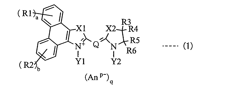
(R1およびR2は各々独立に水酸基、ニトロ基、シアノ基あるいはハロゲン原子、またはアルキル基、アルコキシ基、アリール基、アリールアルキル基あるいはそれらの誘導体であり、aおよびbは各々独立に0~4の整数である。R3~R6は各々独立に水素原子、水酸基、ニトロ基、シアノ基あるいはハロゲン原子、またはアルキル基、アルコキシ基、アリール基、アリールアルキル基あるいはそれらの誘導体であり、R3およびR4のうちの少なくとも一方とR5およびR6のうちの少なくとも一方とはそれぞれ脱離して二重結合を形成してもよいし、それぞれ連結して環構造を形成してもよい。X1は-C(R7)(R8)-で表される基、-N(R9)-で表される基、硫黄原子、酸素原子、セレン原子あるいはテルル原子であり、X2は-C(R10)(R11)-で表される基、-N(R12)-で表される基、硫黄原子、酸素原子、セレン原子あるいはテルル原子である。R7、R8、R10およびR11は各々独立に水素原子あるいは式(2)で表される基、または式(2)に示した基に該当するものを除く、アルキル基、アルコキシ基、アリール基、アリールアルキル基あるいはそれらの誘導体である。R9およびR12は各々独立に水素原子、水酸基、ニトロ基、シアノ基あるいはハロゲン原子、またはアルキル基、アルコキシ基、アリール基、アリールアルキル基あるいはそれらの誘導体である。Y1およびY2は各々独立にアンカー基、またはアルキル基、アルコキシ基、アリール基、アリールアルキル基あるいはそれらの誘導体であり、Y1およびY2のうちの少なくとも一方はアンカー基である。Qは炭素原子数1以上7以下のメチン鎖を骨格とする連結基である。Anp-はp価のアニオンであり、pは1あるいは2であり、qは電荷を中性に保つ係数である。)
(R1 and R2 are each independently a hydroxyl group, a nitro group, a cyano group or a halogen atom, or an alkyl group, an alkoxy group, an aryl group, an arylalkyl group or a derivative thereof, and a and b are each independently 0-4. R3 to R6 are each independently a hydrogen atom, a hydroxyl group, a nitro group, a cyano group or a halogen atom, or an alkyl group, an alkoxy group, an aryl group, an arylalkyl group or a derivative thereof, and among R3 and R4, And at least one of R5 and R6 may be eliminated to form a double bond, or may be linked to form a ring structure, and X1 is —C (R7) ( A group represented by R8) —, a group represented by —N (R9) —, a sulfur atom, an oxygen atom, a selenium atom or a tellurium atom. , X2 is a group represented by —C (R10) (R11) —, a group represented by —N (R12) —, a sulfur atom, an oxygen atom, a selenium atom or a tellurium atom, R7, R8, R10 and R11 is each independently an alkyl group, an alkoxy group, an aryl group, an arylalkyl group or a derivative thereof except a hydrogen atom, a group represented by the formula (2), or a group corresponding to the group represented by the formula (2) R9 and R12 are each independently a hydrogen atom, a hydroxyl group, a nitro group, a cyano group or a halogen atom, or an alkyl group, an alkoxy group, an aryl group, an arylalkyl group, or a derivative thereof Y1 and Y2 are each independently Are an anchor group, an alkyl group, an alkoxy group, an aryl group, an arylalkyl group or a derivative thereof, and Y1 and At least one of the two is an anchor group .Q is an anion of .An p-p-valent is a linkage group that has a methine chain having 1 to 7 carbon atoms as a skeleton, p is 1 or 2 And q is a coefficient that keeps the charge neutral.)
なお、式(1)中で説明した「誘導体」とは、置換基中の水素原子が他の原子あるいは原子団に置換された基のことをいい、水素原子の代わりに導入される原子としては、例えば、ハロゲン原子などが挙げられ、水素原子の代わりに導入される原子団としては、例えば、水酸基、ニトロ基、シアノ基、アシル基、飽和環状炭化水素基、不飽和環状炭化水素基、芳香族環基あるいは複素環基などが挙げられる。また、「脱離して二重結合を形成してもよい」とは、例えば、式(1)に示した、R3およびR4のうちのいずれか一方とR5およびR6のうちのいずれか一方とが脱離して、R3およびR4が導入された炭素原子とR5およびR6が導入された炭素原子との間の結合が二重結合になってもよいことをいう。このことは、後述する式(3)中のR3およびR4が導入された炭素原子とR5およびR6が導入された炭素原子との間の結合についても同様である。また、「アンカー基」とは、化合物を担持するための担持体に対して、化学的あるいは静電的な親和力および結合能を有する基のことをいう。
The “derivative” described in the formula (1) means a group in which a hydrogen atom in a substituent is substituted with another atom or atomic group, and an atom introduced instead of a hydrogen atom is Examples of the atomic group introduced instead of a hydrogen atom include, for example, a hydroxyl group, a nitro group, a cyano group, an acyl group, a saturated cyclic hydrocarbon group, an unsaturated cyclic hydrocarbon group, an aromatic group, and the like. An aromatic group or a heterocyclic group is exemplified. In addition, “may be eliminated to form a double bond” means, for example, that either one of R3 and R4 and one of R5 and R6 shown in formula (1) is By desorption, the bond between the carbon atom into which R3 and R4 are introduced and the carbon atom into which R5 and R6 are introduced may be a double bond. The same applies to the bond between the carbon atom into which R3 and R4 in formula (3) described later are introduced and the carbon atom into which R5 and R6 are introduced. The “anchor group” refers to a group having a chemical or electrostatic affinity and binding ability for a support for supporting a compound.

(L1とT1との間の結合は二重結合あるいは三重結合であり、L1は炭素原子を表し、T1は炭素原子、酸素原子あるいは窒素原子を表し、x、yおよびzは各々独立に0または1である(ただし、T1が酸素原子である場合にはxおよびyは0であり、T1が窒素原子の場合には(y+z)は0あるいは1である。)。R21~R23は各々独立に水素原子、水酸基、ニトロ基、シアノ基、ハロゲン原子、炭素原子数1以上4以下のアルキル基あるいは炭素原子数1以上4以下のハロゲン化アルキル基であり、R24は水素原子、水酸基、ニトロ基、シアノ基、ハロゲン原子、炭素原子数1以上4以下のアルキル基、炭素原子数1以上4以下のアルコキシ基、炭素原子数1以上4以下のハロゲン化アルキル基あるいは炭素原子数1以上4以下のハロゲン化アルコキシ基であり、R21とR24、R22とR23とはそれぞれ連結して環構造を形成してもよい。nは0以上4以下の整数である。)
(The bond between L1 and T1 is a double bond or a triple bond, L1 represents a carbon atom, T1 represents a carbon atom, an oxygen atom or a nitrogen atom, and x, y and z are each independently 0 or (However, when T1 is an oxygen atom, x and y are 0, and when T1 is a nitrogen atom, (y + z) is 0 or 1.) R21 to R23 are each independently A hydrogen atom, a hydroxyl group, a nitro group, a cyano group, a halogen atom, an alkyl group having 1 to 4 carbon atoms or a halogenated alkyl group having 1 to 4 carbon atoms, and R24 is a hydrogen atom, a hydroxyl group, a nitro group, A cyano group, a halogen atom, an alkyl group having 1 to 4 carbon atoms, an alkoxy group having 1 to 4 carbon atoms, a halogenated alkyl group having 1 to 4 carbon atoms, or 1 to 4 carbon atoms A halogenated alkoxy group of the lower, R21 and R24, R22 and may be to form a ring structure, respectively and R23 .n is zero or an integer of 4 or less.)
なお、式(2)中で説明したハロゲン化アルキル基およびハロゲン化アルコキシ基の「ハロゲン化」とは、アルキル基およびアルコキシ基が含む水素原子の一部あるいは全部をハロゲン元素のうちの1種あるいは2種以上の原子で置換された基のことをいう。
The “halogenation” of the halogenated alkyl group and the halogenated alkoxy group described in the formula (2) means that part or all of the hydrogen atoms contained in the alkyl group and the alkoxy group are one kind of halogen elements or A group substituted with two or more atoms.
本発明の光電変換素子用色素および光電変換素子では、式(1)に示したシアニン構造が、メチン鎖骨格(Q)の両端に導入された複素環骨格のうちの少なくとも一方として5員環骨格と縮合したフェナンスレン骨格を含んでいる。これにより、フェナンスレン骨格の代わりにベンゼン骨格あるいはナフタレン骨格を含むシアニン化合物と比較して、光吸収ピーク波長は、分子全体としてのπ共役の広がりによって長波長側にシフトするが、そのピーク強度は確保された状態のまま、光吸収ピークはブロード化する。しかも、式(1)に示したシアニン構造では、複素環骨格中の5員環部分に含まれる窒素原子に結合したY1およびY2のうちの少なくとも一方が、担持体との結合に寄与するアンカー基として機能する。これにより、担持体に担持された状態で光を吸収して励起されると、担持体に対して効率よく電子が注入される。すなわち、式(1)に示したシアニン構造を有する化合物(以下、式(1)に示したシアニン化合物という)では、担持体に担持された状態で光が照射されると、フェナンスレン骨格の代わりにベンゼン骨格あるいはナフタレン骨格を含むシアニン化合物と比較して、広い波長域の光を吸収して励起されると共に、担持体に対して電子を効率よく注入する。よって、色素として式(1)に示したシアニン化合物を用いた光電変換素子では、照射された光量に対して担持体への電子注入量の割合が高くなり、光電変換の効率が向上する。
In the dye for photoelectric conversion element and photoelectric conversion element of the present invention, the cyanine structure represented by the formula (1) is a 5-membered ring skeleton as at least one of the heterocyclic skeletons introduced at both ends of the methine chain skeleton (Q). And a phenanthrene skeleton condensed with. As a result, compared to cyanine compounds containing a benzene skeleton or a naphthalene skeleton instead of a phenanthrene skeleton, the light absorption peak wavelength is shifted to the longer wavelength side due to the spread of π conjugation as a whole molecule, but the peak intensity is secured. In this state, the light absorption peak becomes broad. Moreover, in the cyanine structure represented by the formula (1), at least one of Y1 and Y2 bonded to the nitrogen atom contained in the 5-membered ring portion in the heterocyclic skeleton contributes to the bond with the carrier. Function as. Thereby, when light is absorbed and excited while being carried on the carrier, electrons are efficiently injected into the carrier. That is, in the compound having the cyanine structure represented by the formula (1) (hereinafter referred to as the cyanine compound represented by the formula (1)), when irradiated with light in a state of being supported on the support, instead of the phenanthrene skeleton, Compared with a cyanine compound containing a benzene skeleton or a naphthalene skeleton, it absorbs light in a wide wavelength range and is excited, and efficiently injects electrons into the carrier. Therefore, in the photoelectric conversion element using the cyanine compound represented by the formula (1) as the pigment, the ratio of the amount of electrons injected into the carrier with respect to the irradiated light amount increases, and the efficiency of photoelectric conversion is improved.
本発明の光電変換素子用色素および光電変換素子では、式(1)に示したシアニン化合物は、式(3)で表される構造を有する化合物であってもよい。一般的なシアニン化合物(メチン鎖骨格の両端に複素環骨格が結合した構造を含む化合物)では、そのメチン鎖骨格および複素環骨格を構成する炭素原子とヘテロ原子とが平面上に並んだような構造(平面性が高い構造)になりやすい。分子構造の平面性が高くなると分子同士が会合してダイマーなどの会合体を形成しやすくなり、会合体を形成した色素は、光電変換に寄与しにくくなる。ところが、複素環骨格がインドレニン骨格を含む式(3)に示した化合物では、式(3)中のR7およびR8がメチン鎖骨格および複素環骨格を含む平面に対して上面側および下面側の双方の空間に張り出すように配置されるため、分子全体として平面性が低くなり、会合しにくくなる。これにより、色素として式(3)に示した化合物を用いた光電変換素子では、担持体に担持された色素全体における光電変換に寄与しにくい会合体の割合が低下するため、光電変換の効率が良好になる。
In the photoelectric conversion element dye and photoelectric conversion element of the present invention, the cyanine compound represented by the formula (1) may be a compound having a structure represented by the formula (3). In general cyanine compounds (compounds having a structure in which a heterocyclic skeleton is bonded to both ends of the methine chain skeleton), carbon atoms and heteroatoms constituting the methine chain skeleton and heterocyclic skeleton are arranged on a plane. It tends to be a structure (structure with high flatness). When the planarity of the molecular structure is increased, molecules are likely to associate with each other to form an association such as a dimer, and the dye that has formed the association is less likely to contribute to photoelectric conversion. However, in the compound represented by the formula (3) in which the heterocyclic skeleton includes an indolenine skeleton, R7 and R8 in the formula (3) are on the upper surface side and the lower surface side with respect to the plane including the methine chain skeleton and the heterocyclic skeleton. Since they are arranged so as to protrude into both spaces, the whole molecule has low planarity and is difficult to associate. As a result, in the photoelectric conversion element using the compound represented by the formula (3) as the dye, the ratio of aggregates that hardly contribute to photoelectric conversion in the entire dye supported on the support decreases, so that the efficiency of photoelectric conversion is improved. Become good.

(R1およびR2は各々独立に水酸基、ニトロ基、シアノ基あるいはハロゲン原子、またはアルキル基、アルコキシ基、アリール基、アリールアルキル基あるいはそれらの誘導体であり、aおよびbは各々独立に0~4の整数である。R3~R6は各々独立に水素原子、水酸基、ニトロ基、シアノ基あるいはハロゲン原子、またはアルキル基、アルコキシ基、アリール基、アリールアルキル基あるいはそれらの誘導体であり、R3およびR4のうちの少なくとも一方とR5およびR6のうちの少なくとも一方とはそれぞれ脱離して二重結合を形成してもよいし、それぞれ連結して環構造を形成してもよい。X2は-C(R10)(R11)-で表される基、-N(R12)-で表される基、硫黄原子、酸素原子、セレン原子あるいはテルル原子である。R7、R8、R10およびR11は各々独立に水素原子あるいは上記した式(2)に示した基、または式(2)に示した基に該当するものを除く、アルキル基、アルコキシ基、アリール基、アリールアルキル基あるいはそれらの誘導体である。R12は各々独立に水素原子、水酸基、ニトロ基、シアノ基あるいはハロゲン原子、またはアルキル基、アルコキシ基、アリール基、アリールアルキル基あるいはそれらの誘導体である。Y1およびY2は各々独立にアンカー基、またはアルキル基、アルコキシ基、アリール基、アリールアルキル基あるいはそれらの誘導体であり、Y1およびY2のうちの少なくとも一方はアンカー基である。Qは炭素原子数1以上7以下のメチン鎖を骨格とする連結基である。Anp-はp価のアニオンであり、pは1あるいは2であり、qは電荷を中性に保つ係数である。)
(R1 and R2 are each independently a hydroxyl group, a nitro group, a cyano group or a halogen atom, or an alkyl group, an alkoxy group, an aryl group, an arylalkyl group or a derivative thereof, and a and b are each independently 0-4. R3 to R6 are each independently a hydrogen atom, a hydroxyl group, a nitro group, a cyano group or a halogen atom, or an alkyl group, an alkoxy group, an aryl group, an arylalkyl group or a derivative thereof, and among R3 and R4, And at least one of R5 and R6 may be eliminated to form a double bond, or may be linked to form a ring structure, and X2 is —C (R10) ( R11) — group, —N (R12) — group, sulfur atom, oxygen atom, selenium atom or tellurium source R7, R8, R10 and R11 are each independently an alkyl group, an alkoxy group, excluding a hydrogen atom or a group represented by the above formula (2), or a group corresponding to the group represented by the formula (2), An aryl group, an arylalkyl group or a derivative thereof, each R12 is independently a hydrogen atom, a hydroxyl group, a nitro group, a cyano group or a halogen atom, or an alkyl group, an alkoxy group, an aryl group, an arylalkyl group or a derivative thereof; Y1 and Y2 are each independently an anchor group, an alkyl group, an alkoxy group, an aryl group, an arylalkyl group or a derivative thereof, and at least one of Y1 and Y2 is an anchor group, Q is a carbon atom having 1 to 7 of the following methine chain is a linking group as a skeleton .An p-p-valent anion There, p is 1 or 2, q is a coefficient to maintain neutral electric charge.)
また、本発明の光電変換素子用色素および光電変換素子では、式(1)に示したシアニン化合物は、式(4)で表される構造を有する化合物であってもよい。この場合、式(4)に示した化合物では、式(4)中のR7およびR8と共に、R10およびR11が、メチン鎖骨格および複素環骨格を含む平面に対して上面側および下面側の双方の空間に張り出すように配置されるため、分子全体として平面性がより低くなり、より会合しにくくなる。これにより、色素として式(4)に示した化合物を用いた光電変換素子では、担持体に担持された色素全体における光電変換に寄与しにくい会合体の割合が低下するため、光電変換の効率が良好になる。
In the photoelectric conversion element dye and photoelectric conversion element of the present invention, the cyanine compound represented by the formula (1) may be a compound having a structure represented by the formula (4). In this case, in the compound represented by the formula (4), R10 and R11 together with R7 and R8 in the formula (4) are both on the upper surface side and the lower surface side with respect to the plane including the methine chain skeleton and the heterocyclic skeleton. Since they are arranged so as to protrude into the space, the whole molecule has lower planarity and is less likely to associate. As a result, in the photoelectric conversion element using the compound represented by the formula (4) as the dye, the proportion of aggregates that hardly contribute to photoelectric conversion in the entire dye supported on the support decreases, so that the efficiency of photoelectric conversion is improved. Become good.

(R1およびR2は各々独立に水酸基、ニトロ基、シアノ基あるいはハロゲン原子、またはアルキル基、アルコキシ基、アリール基、アリールアルキル基あるいはそれらの誘導体であり、aおよびbは各々独立に0~4の整数である。R7、R8、R10およびR11は各々独立に水素原子あるいは上記した式(2)に示した基、または式(2)に示した基に該当するものを除く、アルキル基、アルコキシ基、アリール基、アリールアルキル基あるいはそれらの誘導体である。環Aはベンゼン環、ナフタレン環、フェナンスレン環あるいはそれらの誘導体である。Y1およびY2は各々独立にアンカー基、またはアルキル基、アルコキシ基、アリール基、アリールアルキル基あるいはそれらの誘導体であり、Y1およびY2のうちの少なくとも一方はアンカー基である。Qは炭素原子数1以上7以下のメチン鎖を骨格とする連結基である。Anp-はp価のアニオンであり、pは1あるいは2であり、qは電荷を中性に保つ係数である。)
(R1 and R2 are each independently a hydroxyl group, a nitro group, a cyano group or a halogen atom, or an alkyl group, an alkoxy group, an aryl group, an arylalkyl group or a derivative thereof, and a and b are each independently 0-4. R7, R8, R10 and R11 are each independently a hydrogen atom, an alkyl group or an alkoxy group other than those represented by the group represented by the formula (2) or the group represented by the formula (2). A ring is a benzene ring, naphthalene ring, phenanthrene ring or a derivative thereof Y1 and Y2 are each independently an anchor group, an alkyl group, an alkoxy group, an aryl group, an aryl group, an arylalkyl group, or a derivative thereof. A group, an arylalkyl group or a derivative thereof, and at least one of Y1 and Y2 One is an anchor group .Q is .An p-is a linkage group that has a methine chain having 1 to 7 carbon atoms as a skeleton is a p-valent anion, p is 1 or 2, q is the charge Is a neutral coefficient.)
また、本発明の光電変換素子用色素および光電変換素子では、式(1)に示したシアニン化合物は、式(5)で表される構造を有する化合物であってもよい。この場合、式(5)に示した化合物では、メチン鎖骨格の両端に導入された複素環骨格の双方がフェナンスレン骨格を含むため、担持体に対してより効率よく電子が注入される。その上、分子全体として平面性がより低くなり、より会合しにくくなる。これにより、色素として式(5)に示した化合物を用いた光電変換素子では、担持体に担持された色素全体における光電変換に寄与しにくい会合体の割合が低下すると共に、照射された光量に対して担持体への電子注入量の割合が高くなるため、光電変換の効率がさらに向上する。
In the photoelectric conversion element dye and photoelectric conversion element of the present invention, the cyanine compound represented by the formula (1) may be a compound having a structure represented by the formula (5). In this case, in the compound represented by the formula (5), since both of the heterocyclic skeletons introduced at both ends of the methine chain skeleton include the phenanthrene skeleton, electrons are more efficiently injected into the support. In addition, the planarity of the molecule as a whole becomes lower and it becomes more difficult to associate. Thereby, in the photoelectric conversion element using the compound represented by the formula (5) as the dye, the ratio of the aggregate that hardly contributes to the photoelectric conversion in the entire dye supported on the support decreases, and the amount of light irradiated On the other hand, since the ratio of the amount of electrons injected into the carrier increases, the efficiency of photoelectric conversion is further improved.
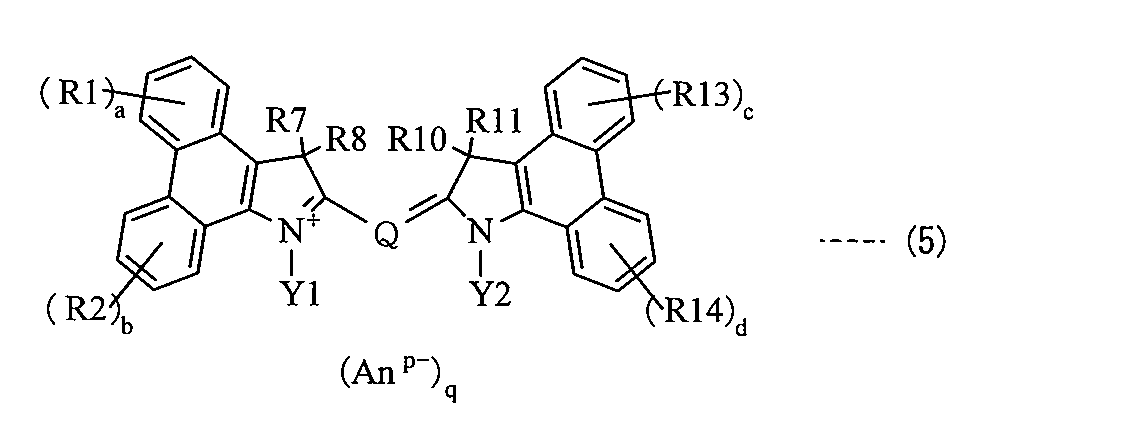
(R1、R2、R13およびR14は各々独立に水酸基、ニトロ基、シアノ基あるいはハロゲン原子、またはアルキル基、アルコキシ基、アリール基、アリールアルキル基あるいはそれらの誘導体であり、a~dは各々独立に0~4の整数である。R7、R8、R10およびR11は各々独立に水素原子あるいは上記した式(2)に示した基、または式(2)に示した基に該当するものを除く、アルキル基、アルコキシ基、アリール基、アリールアルキル基あるいはそれらの誘導体である。Y1およびY2は各々独立にアンカー基、またはアルキル基、アルコキシ基、アリール基、アリールアルキル基あるいはそれらの誘導体であり、Y1およびY2のうちの少なくとも一方はアンカー基である。Qは炭素原子数1以上7以下のメチン鎖を骨格とする連結基である。Anp-はp価のアニオンであり、pは1あるいは2であり、qは電荷を中性に保つ係数である。)
(R1, R2, R13 and R14 are each independently a hydroxyl group, a nitro group, a cyano group or a halogen atom, or an alkyl group, an alkoxy group, an aryl group, an arylalkyl group or a derivative thereof; R is an integer of 0 to 4. R7, R8, R10 and R11 are each independently an alkyl other than a hydrogen atom or a group represented by the above formula (2) or a group represented by the formula (2) A group, an alkoxy group, an aryl group, an arylalkyl group or a derivative thereof Y1 and Y2 are each independently an anchor group, or an alkyl group, an alkoxy group, an aryl group, an arylalkyl group, or a derivative thereof; At least one of Y2 is an anchor group, Q is a methine chain having 1 to 7 carbon atoms. A is .An p-linking group and a p-valent anion, p is 1 or 2, q is a coefficient to maintain neutral electric charge.)
また、本発明の光電変換素子用色素および光電変換素子では、式(1)あるいは式(3)~式(5)に示したR7、R8、R10およびR11のうちの少なくとも1つは、上記した式(2)に示した基であることが好ましい。これにより、立体的に嵩高い式(2)に示した基が、シアニン構造中のメチン鎖骨格および複素環骨格を含む平面に対して上面側および下面側のうちの少なくとも一方の空間に大きく張り出して占有するように配置されるため、分子全体として、より会合しにくい立体的なサイズが大きいものとなる。これにより、この色素を用いた光電変換素子では、担持体に担持された色素全体における光電変換に寄与しにくい会合体の割合がより低下するため、光電変換の効率がさらに向上する。
In the photoelectric conversion element dye and photoelectric conversion element of the present invention, at least one of R7, R8, R10, and R11 shown in Formula (1) or Formula (3) to Formula (5) is as described above. The group shown in Formula (2) is preferable. As a result, the sterically bulky group represented by the formula (2) greatly protrudes into at least one of the upper surface side and the lower surface side with respect to the plane including the methine chain skeleton and the heterocyclic skeleton in the cyanine structure. Therefore, the entire molecule has a large steric size that is less likely to associate. Thereby, in the photoelectric conversion element using this pigment | dye, since the ratio of the aggregate which is hard to contribute to the photoelectric conversion in the whole pigment | dye carry | supported by the support body falls more, the efficiency of photoelectric conversion further improves.
また、本発明の光電変換素子用色素および光電変換素子では、式(1)あるいは式(3)~式(5)に示したアンカー基は、-CH2 -CH2-C(=O)-OHで表される基あるいは-CH2-CH2 -C(=O)-O- で表される基であるのが好ましい。また、式(1)あるいは式(3)~式(5)に示したY1およびY2の双方がアンカー基であることが好ましい。これらにより、担持体から剥離されにくくなるため、照射された光量に対して担持体への電子注入量の割合が高くなり、より良好に光電変換が行われる。さらに、式(1)あるいは式(3)~式(5)に示したQは、メチン鎖骨格にシアノ基が導入された連結基であることが好ましい。これにより、光電変換の効率がさらに向上する。
In the photoelectric conversion element dye and photoelectric conversion element of the present invention, the anchor group represented by formula (1) or formula (3) to formula (5) is —CH 2 —CH 2 —C (═O) —. A group represented by OH or a group represented by —CH 2 —CH 2 —C (═O) —O 2 — is preferred. Further, it is preferable that both Y1 and Y2 shown in the formula (1) or the formulas (3) to (5) are anchor groups. As a result, it becomes difficult to peel off from the carrier, so that the ratio of the amount of electrons injected into the carrier with respect to the amount of irradiated light is increased, and photoelectric conversion is performed better. Further, Q shown in Formula (1) or Formula (3) to Formula (5) is preferably a linking group in which a cyano group is introduced into the methine chain skeleton. Thereby, the efficiency of photoelectric conversion further improves.
さらに、本発明の光電変換素子では、担持体は、酸化亜鉛(ZnO)を含むことが好ましい。これにより、光電変換の効率がさらに向上する。
Furthermore, in the photoelectric conversion element of the present invention, the support preferably contains zinc oxide (ZnO). Thereby, the efficiency of photoelectric conversion further improves.
本発明の光電変換素子用色素によれば、式(1)に示したシアニン構造を有するので、その構造をもたない色素と比較して、広い波長域の光を吸収して励起されると共に、担持された担持体に対する電子注入効率が向上する。よって、本発明の光電変換素子によれば、担持体に担持された色素が式(1)に示したシアニン構造を有する化合物を含むようにしたので、変換効率を向上させることができる。この場合、式(1)に示したR7、R8、R10およびR11のうちの少なくとも1つが上記した式(2)に示した基であれば、会合体の形成がより抑制されるため、より変換効率を向上させることができる。また、式(1)中のY1およびY2の双方がアンカー基であったり、式(1)中のQがメチン鎖骨格にシアノ基が導入された連結基であれば、より高い変換効率を得ることができる。
According to the dye for photoelectric conversion elements of the present invention, since it has the cyanine structure represented by the formula (1), it is excited by absorbing light in a wide wavelength range as compared with a dye having no structure. The electron injection efficiency for the supported carrier is improved. Therefore, according to the photoelectric conversion element of the present invention, since the dye supported on the support contains the compound having the cyanine structure represented by the formula (1), the conversion efficiency can be improved. In this case, if at least one of R7, R8, R10 and R11 shown in the formula (1) is a group shown in the above formula (2), the formation of aggregates is further suppressed, so that the conversion is further performed. Efficiency can be improved. Further, when both Y1 and Y2 in the formula (1) are anchor groups, or Q in the formula (1) is a linking group in which a cyano group is introduced into the methine chain skeleton, higher conversion efficiency is obtained. be able to.
また、特に、色素を担持する担持体が酸化亜鉛を含んでいれば、変換効率をより向上させることができる。
In particular, the conversion efficiency can be further improved if the carrier carrying the dye contains zinc oxide.
以下、本発明の実施の形態について図面を参照して詳細に説明する。
Hereinafter, embodiments of the present invention will be described in detail with reference to the drawings.
本発明の一実施の形態に係る色素は、色素増感型の光電変換素子に用いられるもの(光電変換素子用)であり、式(1)で表されるシアニン構造を有するもの(以下、式(1)に示したシアニン化合物という。)である。式(1)に示したシアニン化合物は、例えば、金属酸化物半導体材料などを含む担持体に対して吸着性(結合性)を有すると共に、光を吸収して励起され、電子をその担持体に対して注入することができる化合物である。
A dye according to an embodiment of the present invention is used for a dye-sensitized photoelectric conversion element (for a photoelectric conversion element) and has a cyanine structure represented by the formula (1) (hereinafter, a formula (Referred to as the cyanine compound shown in (1)). The cyanine compound represented by the formula (1) has, for example, an adsorptive property (bonding property) to a support including a metal oxide semiconductor material, and is excited by absorbing light to the electron. It is a compound that can be injected.
なお、式(1)に示した構造式では、シアニン化合物が、メチン鎖骨格(Q)とその両端に導入された複素環骨格中の2つの窒素原子との間で共鳴構造をとっていることを表している。よって、式(1)では、フェナンスレン環を有する複素環骨格中に含まれる窒素原子(Y1が導入された窒素原子)が正に帯電した状態(N+)の構造式を表しているが、式(1)に示したシアニン化合物は、この構造式で表される構造に限定されるものではない。例えば、式(1)中のY2と結合した窒素原子が正に帯電した状態になっていてもよい。この場合、Y2と結合した窒素原子とその窒素原子のQ側に隣り合った炭素原子との間に二重結合を形成するように、メチン鎖骨格中の炭素原子間の結合、およびY1が導入された窒素原子とその窒素原子のQ側に隣り合った炭素原子との結合において二重結合および単結合が交互になる構造式で表される共鳴構造をとっていてもよい。また、共鳴構造を有するように他の構造式で表されるものであってもよい。このことは、後述する構造式(例えば、式(3)~式(5)などの構造式)においても同様である。
In the structural formula shown in Formula (1), the cyanine compound has a resonance structure between the methine chain skeleton (Q) and two nitrogen atoms in the heterocyclic skeleton introduced at both ends thereof. Represents. Therefore, the formula (1) represents a structural formula in which a nitrogen atom (nitrogen atom introduced with Y1) contained in a heterocyclic skeleton having a phenanthrene ring is positively charged (N + ). The cyanine compound shown in (1) is not limited to the structure represented by this structural formula. For example, the nitrogen atom bonded to Y2 in formula (1) may be in a positively charged state. In this case, a bond between carbon atoms in the methine chain skeleton and Y1 are introduced so as to form a double bond between the nitrogen atom bonded to Y2 and the carbon atom adjacent to the nitrogen atom on the Q side. A resonance structure represented by a structural formula in which double bonds and single bonds alternate in the bond between the formed nitrogen atom and the carbon atom adjacent to the Q side of the nitrogen atom may be employed. Moreover, you may represent with another structural formula so that it may have a resonance structure. The same applies to structural formulas described later (for example, structural formulas such as Formula (3) to Formula (5)).

(R1およびR2は各々独立に水酸基、ニトロ基、シアノ基あるいはハロゲン原子、またはアルキル基、アルコキシ基、アリール基、アリールアルキル基あるいはそれらの誘導体であり、aおよびbは各々独立に0~4の整数である。R3~R6は各々独立に水素原子、水酸基、ニトロ基、シアノ基あるいはハロゲン原子、またはアルキル基、アルコキシ基、アリール基、アリールアルキル基あるいはそれらの誘導体であり、R3およびR4のうちの少なくとも一方とR5およびR6のうちの少なくとも一方とはそれぞれ脱離して二重結合を形成してもよいし、それぞれ連結して環構造を形成してもよい。X1は-C(R7)(R8)-で表される基、-N(R9)-で表される基、硫黄原子、酸素原子、セレン原子あるいはテルル原子であり、X2は-C(R10)(R11)-で表される基、-N(R12)-で表される基、硫黄原子、酸素原子、セレン原子あるいはテルル原子である。R7、R8、R10およびR11は各々独立に水素原子あるいは式(2)で表される基、または式(2)に示した基に該当するものを除く、アルキル基、アルコキシ基、アリール基、アリールアルキル基あるいはそれらの誘導体である。R9およびR12は各々独立に水素原子、水酸基、ニトロ基、シアノ基あるいはハロゲン原子、またはアルキル基、アルコキシ基、アリール基、アリールアルキル基あるいはそれらの誘導体である。Y1およびY2は各々独立にアンカー基、またはアルキル基、アルコキシ基、アリール基、アリールアルキル基あるいはそれらの誘導体であり、Y1およびY2のうちの少なくとも一方はアンカー基である。Qは炭素原子数1以上7以下のメチン鎖を骨格とする連結基である。Anp-はp価のアニオンであり、pは1あるいは2であり、qは電荷を中性に保つ係数である。)
(R1 and R2 are each independently a hydroxyl group, a nitro group, a cyano group or a halogen atom, or an alkyl group, an alkoxy group, an aryl group, an arylalkyl group or a derivative thereof, and a and b are each independently 0-4. R3 to R6 are each independently a hydrogen atom, a hydroxyl group, a nitro group, a cyano group or a halogen atom, or an alkyl group, an alkoxy group, an aryl group, an arylalkyl group or a derivative thereof, and among R3 and R4, And at least one of R5 and R6 may be eliminated to form a double bond, or may be linked to form a ring structure, and X1 is —C (R7) ( A group represented by R8) —, a group represented by —N (R9) —, a sulfur atom, an oxygen atom, a selenium atom or a tellurium atom. , X2 is a group represented by —C (R10) (R11) —, a group represented by —N (R12) —, a sulfur atom, an oxygen atom, a selenium atom or a tellurium atom, R7, R8, R10 and R11 is each independently an alkyl group, an alkoxy group, an aryl group, an arylalkyl group or a derivative thereof except a hydrogen atom, a group represented by the formula (2), or a group corresponding to the group represented by the formula (2) R9 and R12 are each independently a hydrogen atom, a hydroxyl group, a nitro group, a cyano group or a halogen atom, or an alkyl group, an alkoxy group, an aryl group, an arylalkyl group, or a derivative thereof Y1 and Y2 are each independently Are an anchor group, an alkyl group, an alkoxy group, an aryl group, an arylalkyl group or a derivative thereof, and Y1 and At least one of the two is an anchor group .Q is an anion of .An p-p-valent is a linkage group that has a methine chain having 1 to 7 carbon atoms as a skeleton, p is 1 or 2 And q is a coefficient that keeps the charge neutral.)

(L1とT1との間の結合は二重結合あるいは三重結合であり、L1は炭素原子を表し、T1は炭素原子、酸素原子あるいは窒素原子を表し、x、yおよびzは各々独立に0または1である(ただし、T1が酸素原子である場合にはxおよびyは0であり、T1が窒素原子の場合には(y+z)は0あるいは1である。)。R21~R23は各々独立に水素原子、水酸基、ニトロ基、シアノ基、ハロゲン原子、炭素原子数1以上4以下のアルキル基あるいは炭素原子数1以上4以下のハロゲン化アルキル基であり、R24は水素原子、水酸基、ニトロ基、シアノ基、ハロゲン原子、炭素原子数1以上4以下のアルキル基、炭素原子数1以上4以下のアルコキシ基、炭素原子数1以上4以下のハロゲン化アルキル基あるいは炭素原子数1以上4以下のハロゲン化アルコキシ基であり、R21とR24、R22とR23とはそれぞれ連結して環構造を形成してもよい。nは0以上4以下の整数である。)
(The bond between L1 and T1 is a double bond or a triple bond, L1 represents a carbon atom, T1 represents a carbon atom, an oxygen atom or a nitrogen atom, and x, y and z are each independently 0 or (However, when T1 is an oxygen atom, x and y are 0, and when T1 is a nitrogen atom, (y + z) is 0 or 1.) R21 to R23 are each independently A hydrogen atom, a hydroxyl group, a nitro group, a cyano group, a halogen atom, an alkyl group having 1 to 4 carbon atoms or a halogenated alkyl group having 1 to 4 carbon atoms, and R24 is a hydrogen atom, a hydroxyl group, a nitro group, A cyano group, a halogen atom, an alkyl group having 1 to 4 carbon atoms, an alkoxy group having 1 to 4 carbon atoms, a halogenated alkyl group having 1 to 4 carbon atoms, or 1 to 4 carbon atoms A halogenated alkoxy group of the lower, R21 and R24, R22 and may be to form a ring structure, respectively and R23 .n is zero or an integer of 4 or less.)
式(1)に示したシアニン化合物は、メチン鎖骨格(Q)の両端に導入された5員環骨格を含む複素環骨格と、それらの5員環骨格に含まれる窒素原子に結合したY1およびY2のうちの少なくとも一方として導入されたアンカー基とを含んで構成されている。メチン鎖骨格の両端に導入された双方の複素環骨格のうちの少なくとも一方は、5員環骨格と縮合したフェナンスレン骨格を含んでいる。式(1)に示したシアニン化合物では、炭素原子数1以上7以下のメチン鎖骨格を含むことにより、その化合物の光吸収ピーク波長が紫外光域から近赤外光域の間にあることになる。この光吸収ピーク波長は、フェナンスレン骨格を含むことによる分子全体としてのπ共役の広がりによって、フェナンスレン骨格の代わりにベンゼン骨格あるいはナフタレン骨格を含むシアニン化合物の光吸収ピーク波長よりも、長波長側にシフトする。その上、式(1)に示したシアニン化合物の光吸収ピークは、フェナンスレン骨格をもたないシアニン化合物の光吸収ピークよりも、ピーク強度が確保された状態でブロード化する。すなわち、フェナンスレン骨格を含むことにより、式(1)に示したシアニン化合物の光吸収波長域の幅は、フェナンスレン骨格をもたないシアニン化合物の光吸収波長域の幅よりも広くなる。しかも、複素環骨格双方の窒素原子のうちの少なくとも一方に担持体との結合に寄与するアンカー基が導入されていることにより、担持体に担持された状態で光を吸収して励起されると、担持体に対して効率よく電子が注入される。これらによって、式(1)に示したシアニン化合物では、担持体に担持された状態で紫外光域、可視光域および近赤外光域の成分を含む光が照射されると、そのうちの広い波長域の光成分を吸収して励起されて担持体に対して効率よく電子を注入する。よって、式(1)に示したシアニン化合物を用いた光電変換素子では、照射された光量に対して担持体への電子注入量の割合が高くなり、変換効率が向上する。なお、式(1)に示したシアニン化合物では、式(1)中に示した構造を有していれば、その鏡像異性体や、ジアステレオマーであっても同様の効果が得られる。
The cyanine compound represented by the formula (1) includes a heterocyclic skeleton including a 5-membered ring skeleton introduced at both ends of the methine chain skeleton (Q), Y1 bonded to a nitrogen atom contained in the 5-membered ring skeleton, and And an anchor group introduced as at least one of Y2. At least one of both heterocyclic skeletons introduced at both ends of the methine chain skeleton includes a phenanthrene skeleton condensed with a five-membered ring skeleton. The cyanine compound represented by the formula (1) includes a methine chain skeleton having 1 to 7 carbon atoms, so that the light absorption peak wavelength of the compound is between the ultraviolet light region and the near infrared light region. Become. This light absorption peak wavelength shifts to a longer wavelength side than the light absorption peak wavelength of a cyanine compound containing a benzene skeleton or a naphthalene skeleton instead of the phenanthrene skeleton due to the spread of π conjugation as a whole molecule due to the inclusion of the phenanthrene skeleton. To do. In addition, the light absorption peak of the cyanine compound represented by the formula (1) is broadened in a state in which the peak intensity is secured as compared with the light absorption peak of the cyanine compound having no phenanthrene skeleton. That is, by including the phenanthrene skeleton, the width of the light absorption wavelength region of the cyanine compound represented by the formula (1) is wider than the width of the light absorption wavelength region of the cyanine compound having no phenanthrene skeleton. Moreover, when an anchor group that contributes to the bond with the carrier is introduced into at least one of the nitrogen atoms of both the heterocyclic skeletons, it is excited by absorbing light while being carried on the carrier. Electrons are efficiently injected into the carrier. As a result, when the cyanine compound represented by the formula (1) is irradiated with light including components in the ultraviolet light region, visible light region, and near infrared light region in a state of being supported on the carrier, a wide wavelength of the light is emitted. The light component in the region is absorbed and excited, and electrons are efficiently injected into the carrier. Therefore, in the photoelectric conversion element using the cyanine compound represented by the formula (1), the ratio of the amount of electrons injected into the carrier with respect to the irradiated light amount is increased, and the conversion efficiency is improved. In addition, if the cyanine compound shown in Formula (1) has the structure shown in Formula (1), even if it is the enantiomer or diastereomer, the same effect is acquired.
式(1)中で説明したR1およびR2は、フェナンスレン骨格に導入される水素原子(水素基)を除く基を表すものであり、その種類は上記した1価の基のうちのいずれかであれば任意であり、その数(式(1)中のaおよびb)は0~4の間の整数であれば任意である。aとbとの合計が2以上であると共に複数のR1およびR2のうちの2つが隣り合っている場合、隣り合う2つの基同士が結合して環構造を形成してもよいが、合成の容易性の観点から、R1およびR2は、環構造を形成せずに1価の基として導入されていることが好ましい。
R1 and R2 described in the formula (1) represent a group excluding a hydrogen atom (hydrogen group) introduced into the phenanthrene skeleton, and the kind thereof may be any of the monovalent groups described above. The numbers (a and b in the formula (1)) are arbitrary as long as they are integers between 0 and 4. When the sum of a and b is 2 or more and two of R1 and R2 are adjacent to each other, two adjacent groups may be bonded to form a ring structure. From the viewpoint of ease, R1 and R2 are preferably introduced as a monovalent group without forming a ring structure.
R1およびR2がハロゲン原子である場合には、そのハロゲン原子の種類としては、例えば、フッ素原子、塩素原子、臭素原子あるいはヨウ素原子などが挙げられる。
When R1 and R2 are halogen atoms, examples of the halogen atom include a fluorine atom, a chlorine atom, a bromine atom, and an iodine atom.
R1およびR2がアルキル基、アルコキシ基、アリール基、アリールアルキル基あるいはそれらの誘導体である場合には、その骨格を構成する炭素原子数も任意である。この場合におけるアルキル基、アルコキシ基、アリール基、アリールアルキル基あるいはそれらの誘導体としては、例えば、以下のものが挙げられる。すなわち、アルキル基およびその誘導体としては、例えば、メチル基、エチル基、プロピル基、イソプロピル基、ブチル基、第2ブチル基、第3ブチル基、イソブチル基、アミル基、イソアミル基、ヘキシル基、シクロヘキシル基、シクロヘキシルメチル基、シクロヘキシルエチル基、ヘプチル基、イソヘプチル基、第3ヘプチル基、n-オクチル基、イソオクチル基、第3オクチル基、2-エチルヘキシル基、ノニル基、イソノニル基、デシル基、ドデシル基、ヘキサデシル基、ドコシル基あるいはテトラコシル基などの炭素原子数1~25のアルキル基や、それらのハロゲン化された基や、それらの基に対して、フェニル基などの芳香族環基、チオフェン基などの複素環基、アセチル基などのアシル基あるいはカルボン酸基などの酸性基が導入された基などが挙げられる。アルコキシ基およびその誘導体としては、メトキシ基、エトキシ基、プロピルオキシ基、イソプロピルオキシ基、ブチルオキシ基、第2ブチルオキシ基、第3ブチルオキシ基、イソブチルオキシ基、アミルオキシ基、イソアミルオキシ基、第3アミルオキシ基、ヘキシルオキシ基、シクロヘキシルオキシ基、シクロヘキシルメチルオキシ基、シクロヘキシルエチルオキシ基、ヘプチルオキシ基、イソヘプチルオキシ基、第3ヘプチルオキシ基、n-オクチルオキシ基、イソオクチルオキシ基、第3オクチルオキシ基、2-エチルヘキシルオキシ基、ノニルオキシ基、イソノニルオキシ基、デシルオキシ基、ドデシルオキシ基、ヘキサデシルオキシ基あるいはドコシルオキシ基などの炭素原子数1~20のアルコキシ基や、それらのハロゲン化された基や、それらの基に対して、フェニル基などの芳香族環基、チオフェン基などの複素環基、アセチル基などのアシル基あるいはカルボン酸基などの酸性基が導入された基などが挙げられる。アリール基およびその誘導体としては、例えば、フェニル基、ナフチル基、アントラセン-1-イル基、テトラセニル基、ペンタセニル基、クリセニル基、トリフェニレニル基、ピレニル基、ピセニル基あるいはペリレニル基などの炭素原子数6~30のアリール基や、それらのハロゲン化された基や、それらの基に対してメチル基などのアルキル基、メトキシ基などのアルコキシ基、フェニル基などの芳香族環基、チオフェン基などの複素環基、アセチル基などのアシル基あるいはカルボン酸基などの酸性基が導入された基などが挙げられる。アリールアルキル基およびその誘導体としては、例えば、ベンジル基、フェネチル基、2-フェニルプロパン基、ジフェニルメチル基、トリフェニルメチル基、スチリル基、シンナミル基、ナフチルメチル基あるいはビフェニルメチル基などの炭素原子数7~30のアリールアルキル基や、それらのハロゲン化された基や、それらの基に対してメチル基などのアルキル基、メトキシ基などのアルコキシ基、フェニル基などの芳香族環基、チオフェン基などの複素環基、アセチル基などのアシル基あるいはカルボン酸基などの酸性基が導入された基などが挙げられる。
When R1 and R2 are an alkyl group, an alkoxy group, an aryl group, an arylalkyl group or a derivative thereof, the number of carbon atoms constituting the skeleton is also arbitrary. In this case, examples of the alkyl group, alkoxy group, aryl group, arylalkyl group or derivatives thereof include the following. That is, examples of the alkyl group and derivatives thereof include methyl group, ethyl group, propyl group, isopropyl group, butyl group, second butyl group, third butyl group, isobutyl group, amyl group, isoamyl group, hexyl group, and cyclohexyl. Group, cyclohexylmethyl group, cyclohexylethyl group, heptyl group, isoheptyl group, tertiary heptyl group, n-octyl group, isooctyl group, tertiary octyl group, 2-ethylhexyl group, nonyl group, isononyl group, decyl group, dodecyl group Alkyl groups having 1 to 25 carbon atoms such as hexadecyl group, docosyl group or tetracosyl group, halogenated groups thereof, aromatic ring groups such as phenyl groups, thiophene groups, etc. Heterocyclic groups, acyl groups such as acetyl groups or acidic groups such as carboxylic acid groups Etc. introduced group. Alkoxy groups and derivatives thereof include methoxy group, ethoxy group, propyloxy group, isopropyloxy group, butyloxy group, second butyloxy group, third butyloxy group, isobutyloxy group, amyloxy group, isoamyloxy group, third amyloxy group Hexyloxy group, cyclohexyloxy group, cyclohexylmethyloxy group, cyclohexylethyloxy group, heptyloxy group, isoheptyloxy group, third heptyloxy group, n-octyloxy group, isooctyloxy group, third octyloxy group An alkoxy group having 1 to 20 carbon atoms such as 2-ethylhexyloxy group, nonyloxy group, isononyloxy group, decyloxy group, dodecyloxy group, hexadecyloxy group or docosyloxy group, and halogenation thereof. Groups in which an aromatic group such as a phenyl group, a heterocyclic group such as a thiophene group, an acyl group such as an acetyl group, or an acidic group such as a carboxylic acid group is introduced. Can be mentioned. Examples of the aryl group and derivatives thereof include 6 to 6 carbon atoms such as phenyl group, naphthyl group, anthracen-1-yl group, tetracenyl group, pentacenyl group, chrysenyl group, triphenylenyl group, pyrenyl group, picenyl group, and perylenyl group. 30 aryl groups, halogenated groups thereof, alkyl groups such as methyl groups, alkoxy groups such as methoxy groups, aromatic ring groups such as phenyl groups, and heterocyclic rings such as thiophene groups Group, an acyl group such as an acetyl group, or a group into which an acidic group such as a carboxylic acid group has been introduced. Examples of the arylalkyl group and derivatives thereof include carbon atoms such as benzyl group, phenethyl group, 2-phenylpropane group, diphenylmethyl group, triphenylmethyl group, styryl group, cinnamyl group, naphthylmethyl group or biphenylmethyl group. 7-30 arylalkyl groups, halogenated groups thereof, alkyl groups such as methyl groups, alkoxy groups such as methoxy groups, aromatic ring groups such as phenyl groups, thiophene groups, etc. A heterocyclic group, an acyl group such as an acetyl group, or a group introduced with an acidic group such as a carboxylic acid group.
式(1)中で説明したR3~R6は、式(1)中においてフェナンスレン骨格をもっていない側の5員複素環が含む炭素原子に導入される基であり、上記した1価の基のうちのいずれかであれば任意である。R3~R6の具体例としては、水素原子(水素基)の他に、例えば、R1およびR2として導入される1価の基と同様のものが挙げられる。中でも、R3~R6のうちの少なくとも1つは、炭素原子数1以上25以下のアルキル基、炭素原子数1以上20以下のアルコキシ基、アリール基、アリールアルキル基あるいはそれらの誘導体であるのが好ましい。一般的なシアニン化合物(メチン鎖骨格の両端に複素環骨格が結合した構造を含む化合物)では、そのメチン鎖骨格および複素環骨格を構成する炭素原子およびヘテロ原子が平面上に並んだような構造、いわゆる平面性が高い構造になりやすい。分子構造の平面性が高くなると分子同士が重なり合うように会合してダイマーなどの会合体を形成しやすくなる。会合体を形成した色素は、担持体に担持されても電子注入の効率が低くなるため、光電変換に寄与しにくくなる。ところが、複素環骨格が含む炭素原子に導入されるR3~R6は、その炭素原子間において二重結合が形成されていなければ、メチン鎖骨格および複素環骨格を含む平面に対して上面側および下面側の双方の空間に張り出すように配置されることになる。このため、R3~R6のうちのいずれか1つとして上記した基が導入されると、分子全体として平面性が低くなり、分子同士が会合しにくくなる。よって、光電変換素子に用いた場合に、担持された色素全体における光電変換に寄与しにくい会合体の割合を低下させるため、高い変換効率が得られる。中でも、R3~R6のうちの少なくとも1つは、炭素原子数6以上25以下のアルキル基、炭素数5以上20以下のアルコキシ基、アリール基、アリールアルキル基あるいはそれらの誘導体などの立体的に嵩高い基であることが好ましい。より会合体の形成が抑制され、高い効果が得られるからである。
R3 to R6 described in the formula (1) are groups introduced into the carbon atom contained in the 5-membered heterocyclic ring on the side having no phenanthrene skeleton in the formula (1). Any one is optional. Specific examples of R3 to R6 include, in addition to a hydrogen atom (hydrogen group), for example, the same monovalent groups introduced as R1 and R2. Among them, at least one of R3 to R6 is preferably an alkyl group having 1 to 25 carbon atoms, an alkoxy group having 1 to 20 carbon atoms, an aryl group, an arylalkyl group, or a derivative thereof. . In general cyanine compounds (compounds having a structure in which a heterocyclic skeleton is bonded to both ends of the methine chain skeleton), a structure in which carbon atoms and heteroatoms constituting the methine chain skeleton and the heterocyclic skeleton are arranged in a plane It tends to be a structure with high so-called flatness. When the planarity of the molecular structure is high, molecules are associated with each other so as to overlap each other, and an aggregate such as a dimer is easily formed. The dye that forms the aggregate is less likely to contribute to photoelectric conversion because the efficiency of electron injection is low even if it is supported on the support. However, R3 to R6 introduced into the carbon atoms included in the heterocyclic skeleton are on the upper surface side and the lower surface with respect to the plane including the methine chain skeleton and the heterocyclic skeleton unless a double bond is formed between the carbon atoms. It arrange | positions so that it may overhang into the space of both sides. Therefore, when the above-described group is introduced as any one of R3 to R6, the planarity of the molecule as a whole is lowered, and the molecules are difficult to associate with each other. Therefore, when used in a photoelectric conversion element, the ratio of the aggregate that hardly contributes to photoelectric conversion in the entire supported dye is reduced, so that high conversion efficiency is obtained. Among them, at least one of R3 to R6 is sterically bulky such as an alkyl group having 6 to 25 carbon atoms, an alkoxy group having 5 to 20 carbon atoms, an aryl group, an arylalkyl group, or a derivative thereof. A high group is preferred. This is because the formation of aggregates is further suppressed and a high effect is obtained.
ただし、式(1)中にも説明したように、R3およびR4のうちの少なくとも一方とR5およびR6のうちの少なくとも一方とは、脱離して二重結合を形成してもよいし、それぞれ連結して環構造を形成してもよい。もちろん、R3およびR4のうちの一方とR5およびR6のうちの一方とが脱離して二重結合を形成すると共に脱離していないR3およびR4のうちの他方とR5およびR6のうちの他方とが連結して環構造を形成してもよい。このように連結して形成される環構造としては、例えば、ベンゼン環、ナフタレン環、アントラセン環、フェナンスレン環、シクロヘキサン環、シクロブタン環、シクロペンタン環、シクロヘキセン環、シクロへプタン環、ピペリジン環、ピベラジン環、ピロリジン環、モルフォリン環、チオモルフォリン環、ピリジン環、ピラジン環、ピリミジン環、ピリダジン環、トリアジン環、キノリン環、イソキノリン環、イミダゾール環、オキサゾール環あるいはイミダゾリジン環などが挙げられる。この環構造は、これらの他、上記した複数の環構造がさらに縮合した構造でもよいし、さらに1種あるいは2種以上の置換基を有するそれらの誘導体であってもよい。中でも、R3~R6において連結して形成される場合の環構造としては、ベンゼン環、ナフタレン環、フェナンスレン環あるいはそれらの誘導体が好ましい。それら以外の環構造が形成された場合と比較して、担持体に対する電子注入効率が高くなりやすいからである。
However, as described in formula (1), at least one of R3 and R4 and at least one of R5 and R6 may be eliminated to form a double bond, or each Thus, a ring structure may be formed. Of course, one of R3 and R4 and one of R5 and R6 are eliminated to form a double bond, and the other of R3 and R4 that is not eliminated and the other of R5 and R6 are They may be linked to form a ring structure. Examples of the ring structure formed by linking in this way include, for example, a benzene ring, naphthalene ring, anthracene ring, phenanthrene ring, cyclohexane ring, cyclobutane ring, cyclopentane ring, cyclohexene ring, cycloheptane ring, piperidine ring, and piperazine. Ring, pyrrolidine ring, morpholine ring, thiomorpholine ring, pyridine ring, pyrazine ring, pyrimidine ring, pyridazine ring, triazine ring, quinoline ring, isoquinoline ring, imidazole ring, oxazole ring or imidazolidine ring. In addition to these, the ring structure may be a structure obtained by further condensing the plurality of ring structures described above, or may be a derivative thereof having one or more substituents. Among them, the ring structure formed by linking at R3 to R6 is preferably a benzene ring, a naphthalene ring, a phenanthrene ring or a derivative thereof. This is because the electron injection efficiency into the carrier is likely to be higher than in the case where other ring structures are formed.
式(1)中で説明したX1およびX2は、上記した2価の基のうちのいずれかであれば任意である。X1,X2が、炭素原子を含む2価の基(-C(R7)(R8)-あるいは-C(R10)(R11)-)である場合には、そのR7、R8、R10およびR11は、上記した1価の基であれば任意である。R7、R8、R10およびR11の具体例としては、例えば、水素原子の他、後述する式(2)に示した基に該当するものを除く、上記したR1~R6において説明したアルキル基、アルコキシ基、アリール基、アリールアルキル基あるいはその誘導体と同様のものが挙げられる。また、X1,X2が、窒素原子を含む2価の基(-N(R9)-あるいは-N(R12)-)である場合には、そのR9およびR12としては、例えば、上記したR1~R6として導入される基と同様のものなどが挙げられる。
X1 and X2 described in Formula (1) are arbitrary as long as they are any of the above-described divalent groups. When X1 and X2 are divalent groups containing carbon atoms (—C (R7) (R8) — or —C (R10) (R11) —), R7, R8, R10 and R11 are Any monovalent group described above may be used. Specific examples of R7, R8, R10 and R11 include, for example, a hydrogen atom, an alkyl group and an alkoxy group described in R1 to R6 described above except those corresponding to the group shown in the formula (2) described later. , An aryl group, an arylalkyl group or a derivative thereof. When X1 and X2 are divalent groups containing a nitrogen atom (—N (R9) — or —N (R12) —), examples of R9 and R12 include R1 to R6 described above. And the same groups as those introduced as above.
また、式(1)中のR7、R8、R10およびR11は、式(2)に示した基であってもよく、式(2)に示した基は、上記した構造を有する基であれば任意である。式(2)中で説明したハロゲン原子としては、式(1)中で説明したハロゲン原子と同様のものが挙げられる。式(2)に示した基としては、例えば、ビニル基(-CH=CH2)、アリル基(-CH2-CH=CH2 )、1-プロペニル基(-CH=CH-CH3 )、イソプロペニル基(-C(CH3)=CH2)、1-ブテニル基(-CH=CH-CH2 -CH3 )、2-ブテニル基(-CH2-CH=CH-CH3)、2-メチルアリル基(-CH2 -C(CH3 )=CH2)、2-ペンテニル基(-CH2-CH=CH-CH2 -CH3 )、エチニル基(-C≡CH)、2-プロピニル基(-CH2-C≡CH)、1-プロピニル基(-C≡C-CH3)、2-ブチニル基(-CH2-C≡C-CH3)あるいは3-ブチニル基(-CH2 -CH2-C≡CH)などの不飽和鎖式炭化水素基や、フォルミル基、アセチル基、プロピオニル基、ブチリル基、バレリル基、イソバレリル基、ピバロイル基あるいはヘキサノイル基などのアシル基または炭素原子数1以上4以下のアルキル鎖の末端にそれらのアシル基を有する基や、カルボン酸エステル結合(-C(=O)-O-)を有する基や、C=N結合を有する基や、シアノ基あるいは炭素原子数1以上4以下のアルキル鎖の末端にシアノ基を有する基などが挙げられる。また、R21とR24、あるいはR22とR23とが連結して環構造を形成した場合の式(2)に示した基としては、例えば、シクロヘキセニル基あるいはフェニチル基や、式(2-1)に示したベンジル基や、式(2-2)に示したトリルメチル基(メチルベンジル基)や、その他、式(2-3)~式(2-6)で表される基などが挙げられる。なお、これらの基が有する水素原子の一部あるいは全部はハロゲン原子に置換されていてもよい。
In addition, R7, R8, R10 and R11 in the formula (1) may be a group shown in the formula (2), and the group shown in the formula (2) is a group having the structure described above. Is optional. Examples of the halogen atom described in formula (2) include the same halogen atoms as described in formula (1). Examples of the group represented by the formula (2) include a vinyl group (—CH═CH 2 ), an allyl group (—CH 2 —CH═CH 2 ), a 1-propenyl group (—CH═CH—CH 3 ), Isopropenyl group (—C (CH 3 ) ═CH 2 ), 1-butenyl group (—CH═CH—CH 2 —CH 3 ), 2-butenyl group (—CH 2 —CH═CH—CH 3 ), 2 —Methylallyl group (—CH 2 —C (CH 3 ) ═CH 2 ), 2-pentenyl group (—CH 2 —CH═CH—CH 2 —CH 3 ), ethynyl group (—C≡CH), 2-propynyl Group (—CH 2 —C≡CH), 1-propynyl group (—C≡C—CH 3 ), 2-butynyl group (—CH 2 —C≡C—CH 3 ) or 3-butynyl group (—CH 2 -CH 2 -C≡CH) and unsaturated chain hydrocarbon groups such as formyl group, acetyl group, propionyl group, Bed An acyl group such as a tolyl group, a valeryl group, an isovaleryl group, a pivaloyl group or a hexanoyl group, or a group having such an acyl group at the terminal of an alkyl chain having 1 to 4 carbon atoms, or a carboxylic acid ester bond (—C (= And a group having O) —O—), a group having a C═N bond, a cyano group, or a group having a cyano group at the end of an alkyl chain having 1 to 4 carbon atoms. Examples of the group shown in Formula (2) when R21 and R24 or R22 and R23 are linked to form a ring structure include, for example, a cyclohexenyl group, a phenethyl group, and Formula (2-1). And the groups represented by the formulas (2-3) to (2-6), and the like, such as the benzyl group shown, the tolylmethyl group (methylbenzyl group) shown in the formula (2-2), and the like. Note that some or all of the hydrogen atoms contained in these groups may be substituted with halogen atoms.

式(1)中のX1は、中でも、-C(R7)(R8)-あるいは-N(R9)-で表される基であるのが好ましく、-C(R7)(R8)-で表される基であることがより好ましい。また、同様に、式(1)中のX2は、中でも、-C(R10)(R11)-あるいは-N(R12)-で表される基であるのが好ましく、-C(R10)(R11)-で表される基であることがより好ましい。分子全体として平面性が低くなるため、会合体の形成が抑制され、変換効率の向上に寄与しやすくなるからである。これらの場合には、特に、R7~R12は、分子全体の立体的サイズが大きくなるように、上記のような立体的に嵩高い基であるのが好ましい。平面性がより低くなるため、より高い効果が得られるからである。特に、X1およびX2は、それぞれ-C(R7)(R8)-および-C(R10)(R11)-で表される基であることが好ましい。これにより、R7、R8、R10およびR11がメチン鎖骨格および複素環骨格を含む平面に対して上面側および下面側の双方の空間に張り出すように配置されることになるため、分子全体としての平面性が低くなり、分子同士が会合しにくくなることによって変換効率の向上により寄与する。この場合には、R7、R8、R10およびR11のうちの少なくとも1つは、立体的に嵩高いことから、中でも、炭素原子数6以上25以下のアルキル基あるいは式(2)に示した基であることが好ましい。分子全体としての平面性がさらに低くなり、高い会合抑制作用が得られるからである。
X1 in the formula (1) is preferably a group represented by —C (R7) (R8) — or —N (R9) —, and represented by —C (R7) (R8) —. More preferably, it is a group. Similarly, X2 in the formula (1) is preferably a group represented by —C (R10) (R11) — or —N (R12) —, and in particular, —C (R10) (R11 )-Is more preferable. This is because the planarity of the molecule as a whole is lowered, so that the formation of aggregates is suppressed and the conversion efficiency is easily improved. In these cases, it is particularly preferable that R7 to R12 be a sterically bulky group as described above so that the steric size of the entire molecule is increased. This is because the flatness becomes lower and higher effects can be obtained. In particular, X1 and X2 are preferably groups represented by —C (R7) (R8) — and —C (R10) (R11) —, respectively. As a result, R7, R8, R10 and R11 are arranged so as to project into both the upper surface side and the lower surface side of the plane including the methine chain skeleton and the heterocyclic skeleton. The flatness is lowered and the molecules are less likely to associate with each other, thereby contributing to an improvement in conversion efficiency. In this case, since at least one of R7, R8, R10 and R11 is sterically bulky, among them, an alkyl group having 6 to 25 carbon atoms or a group represented by the formula (2) Preferably there is. This is because the planarity of the whole molecule is further lowered, and a high association inhibitory action can be obtained.
R7、R8、R10あるいはR11のいずれか2つが立体的に嵩高い基である場合には、立体的に嵩高い基は、R7およびR8、あるいはR10およびR11として導入されることが好ましい。R7およびR10、あるいはR8およびR11として導入されるよりも、メチン鎖骨格および複素環骨格を含む平面に対して上面側および下面側の双方の空間を占有するように大きく張り出して配置されることになるため、分子全体としての平面性がより低下し、立体的な分子構造となりやすいからである。もちろん、より高い会合抑制作用を得るためには、R7、R8、R10あるいはR11として導入される立体的に嵩高い基の数は、2つよりも3つのほうが好ましく、3つよりも4つのほうがさらに好ましい。
When any two of R7, R8, R10 or R11 are sterically bulky groups, the sterically bulky group is preferably introduced as R7 and R8, or R10 and R11. Rather than being introduced as R7 and R10, or R8 and R11, it is arranged so as to overhang so as to occupy both the upper surface side and the lower surface side of the plane including the methine chain skeleton and the heterocyclic skeleton. Therefore, the planarity of the whole molecule is further lowered, and a three-dimensional molecular structure is easily obtained. Of course, in order to obtain a higher association inhibitory action, the number of sterically bulky groups introduced as R7, R8, R10 or R11 is preferably three rather than two and four more than three. Further preferred.
式(1)中で説明したY1およびY2は、上記した1価の基であれば任意である。Y1およびY2のうちの少なくとも一方が担持体に対して化学的あるいは静電的な親和力および結合能を化合物に付与するアンカー基であることにより、担持体に担持されると共に担持体に対して効率よく電子が注入される。中でも、Y1およびY2の双方がアンカー基であることが好ましい。担持体からの剥離がより抑制されると共に、担持体に対する電子注入効率がより高くなるからである。アンカー基としては、例えば、式(6)で表される基などが挙げられる。式(6)中で説明したR30は、(e+1)価の飽和炭化水素基であれば、その構造や炭素原子数は任意である。また、Z1は、担持体と結合あるいは吸着するための官能基であり、式(6)中に1以上含まれていればその数(e)は任意である。Z1としては、例えば、カルボン酸基、スルホン酸基、リン酸基、カルボン酸イオン基、スルホン酸イオン基あるいはリン酸イオン基などが挙げられる。中でも、式(6)中のR30の炭素原子数は1以上4以下であると共に、Z1がカルボン酸基あるいはカルボン酸イオン基であるのが好ましく、特に、R30が炭素原子数2の2価の基(エチレン基)であると共にZ1がカルボン酸基あるいはカルボン酸イオン基である、-CH2-CH2-C(=O)-OHで表される基あるいは-CH2 -CH2 -C(=O)-O-で表される基であるのが好ましい。カルボン酸基およびカルボン酸イオン基は、担持体との結合能が高く、しかも高い電子吸引性を有する官能基であるので、上記した炭素原子数の範囲のR30と組み合わさることにより、電子注入効率および定着性がより高くなるからである。なお、アンカー基は、式(1)中のY1およびY2の少なくとも一方として導入されていれば、式(1)に示したシアニン構造中に他にも含まれていてもよい。
Y1 and Y2 described in the formula (1) are arbitrary as long as they are monovalent groups as described above. Since at least one of Y1 and Y2 is an anchor group that imparts chemical or electrostatic affinity and binding ability to the support to the compound, it is supported on the support and is efficient with respect to the support. Electrons are often injected. Especially, it is preferable that both Y1 and Y2 are anchor groups. This is because peeling from the carrier is further suppressed, and electron injection efficiency to the carrier is further increased. Examples of the anchor group include a group represented by the formula (6). If R30 demonstrated in Formula (6) is a (e + 1) valent saturated hydrocarbon group, the structure and the number of carbon atoms are arbitrary. Z1 is a functional group for binding or adsorbing to the carrier, and the number (e) is arbitrary as long as it is contained in the formula (6) at least one. Examples of Z1 include a carboxylic acid group, a sulfonic acid group, a phosphoric acid group, a carboxylic acid ion group, a sulfonic acid ion group, and a phosphoric acid ion group. Among them, the number of carbon atoms of R30 in formula (6) is 1 or more and 4 or less, and Z1 is preferably a carboxylic acid group or a carboxylic acid ion group. In particular, R30 is a divalent divalent having 2 carbon atoms. A group represented by —CH 2 —CH 2 —C (═O) —OH, or a group represented by —CH 2 —CH 2 —C ( It is preferably a group represented by ═O) —O 2 — . Since the carboxylic acid group and the carboxylate ion group are functional groups having a high binding ability to the support and high electron withdrawing ability, the electron injection efficiency can be obtained by combining with R30 in the above-mentioned range of the number of carbon atoms. This is because the fixability becomes higher. The anchor group may be included in the cyanine structure shown in the formula (1) as long as it is introduced as at least one of Y1 and Y2 in the formula (1).

(R30は(e+1)価の飽和炭化水素基であり、Z1は酸性基あるいはその酸性基がイオン化した基であり、eは1以上の整数である。)
(R30 is an (e + 1) -valent saturated hydrocarbon group, Z1 is an acidic group or a group obtained by ionizing the acidic group, and e is an integer of 1 or more.)
式(1)中で説明したQは、炭素原子数1以上7以下のメチン鎖(モノメチン~へプタメチン)を骨格とする連結基であれば任意であり、さらに置換基を有していてもよいし、その置換基が互いに結合して環構造を形成していてもよい。メチン鎖の炭素原子数が1以上7以下であるのは、紫外光から近赤外光までの広い範囲における光の吸収が良好となるからである。Qは、メチン鎖骨格を構成する炭素原子に対して1あるいは2以上のシアノ基が導入されていることが好ましい。これにより、担持体に対する定着性および電子注入効率が高くなり、変換効率の向上に寄与する。式(1)中のQとしては、例えば、式(7)で表される連結基が挙げられる。
Q described in formula (1) is arbitrary as long as it is a linking group having a methine chain (monomethine to heptamethine) having 1 to 7 carbon atoms as a skeleton, and may further have a substituent. The substituents may be bonded to each other to form a ring structure. The reason why the number of carbon atoms in the methine chain is 1 or more and 7 or less is that light absorption in a wide range from ultraviolet light to near infrared light becomes good. Q preferably has one or more cyano groups introduced to the carbon atoms constituting the methine chain skeleton. Thereby, the fixability to the carrier and the electron injection efficiency are increased, which contributes to the improvement of the conversion efficiency. As Q in Formula (1), the coupling group represented by Formula (7) is mentioned, for example.

(R40~R42は各々独立に水素原子あるいは置換基であり、複数のR40および複数のR41を有する場合にはR40同士あるいはR41同士はそれぞれ互いに同一であってもよいし、異なっていてもよく、R40~R42のうちの隣り合うもの同士は結合して環状構造を形成してもよい。mは0~3の整数である。)
(R40 to R42 are each independently a hydrogen atom or a substituent, and when having a plurality of R40s and a plurality of R41s, R40s or R41s may be the same as or different from each other. Adjacent ones of R40 to R42 may be bonded to form a cyclic structure, and m is an integer of 0 to 3.)
式(7)で表される連結基は、メチン鎖骨格を構成する炭素原子数が1~7のうちの奇数のものを表している。式(7)に示したようにメチン鎖骨格の炭素原子数が奇数であるQにおいて置換基が導入される場合には、メチン鎖骨格の中心となる炭素原子に置換基が導入されていることが好ましい。分子全体としての電荷の偏りのバランスが良好となり、担持体に対する電子注入効率が高まりやすいからである。この場合の置換基としては、シアノ基がより好ましい。電荷のバランスがよくなる上に、変換効率の向上に寄与しやすいからである。式(7)に示した連結基の具体例としては、例えば、式(7-1)~式(7-10)で表される連結基などが挙げられる。式(7-1)~式(7-4)に示した連結基は、環構造をもたない連結基の具体例であり、式(7-5)~式(7-10)に示した連結基は、環構造を有する場合の具体例である。また、この場合のメチン鎖骨格の中心となる炭素原子に置換基が導入された連結基としては、例えば、式(7-1)~式(7-10)中のR43として置換基が導入されたものなどが挙げられる。
The linking group represented by the formula (7) represents an odd number of 1 to 7 carbon atoms constituting the methine chain skeleton. When a substituent is introduced at Q where the number of carbon atoms in the methine chain skeleton is an odd number as shown in Formula (7), the substituent is introduced at the carbon atom that is the center of the methine chain skeleton. Is preferred. This is because the balance of charge bias as a whole molecule is good, and the electron injection efficiency to the carrier is likely to increase. In this case, the substituent is more preferably a cyano group. This is because the charge balance is improved and the conversion efficiency is easily improved. Specific examples of the linking group represented by the formula (7) include linking groups represented by the formulas (7-1) to (7-10). The linking groups represented by formulas (7-1) to (7-4) are specific examples of linking groups having no ring structure, and are represented by formulas (7-5) to (7-10). The linking group is a specific example in the case of having a ring structure. In this case, examples of the linking group in which a substituent is introduced into the carbon atom that is the center of the methine chain skeleton include a substituent introduced as R43 in the formulas (7-1) to (7-10). Etc.

(R43~R49は各々独立に水素原子、水酸基、ハロゲン原子、シアノ基、炭素原子数6以上30以下のアリール基、ジフェニルアミノ基、炭素原子数1以上8以下のアルキル基あるいは炭素原子数1以上8以下のアルコキシ基である。)
(R43 to R49 are each independently a hydrogen atom, a hydroxyl group, a halogen atom, a cyano group, an aryl group having 6 to 30 carbon atoms, a diphenylamino group, an alkyl group having 1 to 8 carbon atoms, or one or more carbon atoms. 8 or less alkoxy groups.)
式(1)中で説明したAnp-は、式(1)に示したシアニン化合物全体の電荷を中性に保つためのカウンターアニオンであり、1価あるいは2価のアニオンであれば任意である。p=1の場合のアニオン(1価のアニオン;An-)としては、例えば、フッ化物イオン(F-)、塩化物イオン(Cl- )、臭化物イオン(Br-)あるいはヨウ化物イオン(I- )などのハロゲン化物イオンや、ヘキサフルオロリン酸イオン(PF6
-)、ヘキサフルオロアンチモン酸イオン(SbF6
-)、過塩素酸イオン(ClO4
-)、テトラフルオロホウ酸イオン(BF4
-)、塩素酸イオンあるいはチオシアン酸イオンなどの無機系陰イオンや、ベンゼンスルホン酸イオン、トルエンスルホン酸イオン、トリフルオロメタンスルホン酸イオン、ジフェニルアミン-4-スルホン酸イオン、2-アミノ-4-メチル-5-クロロベンゼンスルホン酸イオン、2-アミノ-5-ニトロベンゼンスルホン酸イオン、N-アルキルジフェニルアミン-4-スルホン酸イオンあるいはN-アリールジフェニルアミン-4-スルホン酸イオンなどの有機スルホン酸系陰イオンや、オクチルリン酸イオン、ドデシルリン酸イオン、オクタデシルリン酸イオン、フェニルリン酸イオン、ノニルフェニルリン酸イオンあるいは2,2’-メチレンビス(4,6-ジ-t-ブチルフェニル)ホスホン酸イオンなどの有機リン酸系陰イオンや、その他にビストリフルオロメチルスルホニルイミドイオン、ビスパーフルオロブタンスルホニルイミドイオン、パーフルオロ-4-エチルシクロヘキサンスルホン酸イオン、テトラキス(ペンタフルオロフェニル)ホウ酸イオンあるいはトリス(フルオロアルキルスルホニル)カルボアニオンなどが挙げられる。また、p=2の場合のアニオン(2価のアニオン;An2-)としては、例えば、硫酸イオン(SO4
2-)、ベンゼンジスルホン酸イオンあるいはナフタレンジスルホン酸イオンなどが挙げられる。また、式(1)中で説明したqは、式(1)に示したシアニン化合物全体として電荷を中性に保つ係数であり、0であってもよい。q=0の場合には、例えば、式(1)中のY1およびY2のうちのいずれか一方が1価のイオン基を有することとなり、分子内で塩を形成して、いわゆる内部塩となる。また、q=1の場合には、Anp-が1価のアニオンであるAn-となり、化合物全体の電荷を中性に保つように塩を形成する。また、Anp-が2価のアニオンであるAn2-の場合には、q=1/2となる。すなわち、qは0あるいは1/pである。
An p− described in the formula (1) is a counter anion for maintaining the charge of the whole cyanine compound shown in the formula (1) to be neutral, and is arbitrary as long as it is a monovalent or divalent anion. . As an anion (monovalent anion; An − ) when p = 1, for example, fluoride ion (F − ), chloride ion (Cl − ), bromide ion (Br − ) or iodide ion (I −) ), Hexafluorophosphate ions (PF 6 − ), hexafluoroantimonate ions (SbF 6 − ), perchlorate ions (ClO 4 − ), tetrafluoroborate ions (BF 4 − ) Inorganic anions such as chlorate ion or thiocyanate ion, benzenesulfonate ion, toluenesulfonate ion, trifluoromethanesulfonate ion, diphenylamine-4-sulfonate ion, 2-amino-4-methyl-5- Chlorobenzenesulfonate ion, 2-amino-5-nitrobenzenesulfonate ion, N-alkyldiphe Organic sulfonate anions such as ruamine-4-sulfonate ion or N-aryldiphenylamine-4-sulfonate ion, octyl phosphate ion, dodecyl phosphate ion, octadecyl phosphate ion, phenyl phosphate ion, nonyl phenyl phosphorus Organic phosphate anions such as acid ion or 2,2'-methylenebis (4,6-di-t-butylphenyl) phosphonate ion, bistrifluoromethylsulfonylimide ion, bisperfluorobutanesulfonylimide ion Perfluoro-4-ethylcyclohexanesulfonate ion, tetrakis (pentafluorophenyl) borate ion, tris (fluoroalkylsulfonyl) carboanion, and the like. Examples of the anion (divalent anion; An 2− ) in the case of p = 2 include sulfate ion (SO 4 2− ), benzenedisulfonate ion or naphthalene disulfonate ion. Moreover, q demonstrated in Formula (1) is a coefficient which keeps an electric charge neutral as the whole cyanine compound shown in Formula (1), and may be 0. In the case of q = 0, for example, one of Y1 and Y2 in formula (1) has a monovalent ionic group, and forms a salt in the molecule to become a so-called internal salt. . In addition, when q = 1, An p− becomes a monovalent anion, An − , and a salt is formed so as to keep the charge of the entire compound neutral. In addition, when An p− is An 2− which is a divalent anion, q = ½. That is, q is 0 or 1 / p.
式(1)に示したシアニン化合物は、X1を-C(R7)(R8)-で表される2価の基とした式(3)で表される構造を有する化合物(以下、式(3)に示した化合物という)であるのが好ましい。上記したように、会合体の形成が抑制されるため、変換効率の向上に寄与するからである。式(3)中で説明したR1~R8、X2、R10~R12、Y1、Y2および(Anp-)qとしては、式(1)中のR1~R8、X2、R10~R12、Y1、Y2および(Anp-)qと同様のものが挙げられる。
The cyanine compound represented by the formula (1) is a compound having a structure represented by the formula (3) in which X1 is a divalent group represented by —C (R7) (R8) — (hereinafter, represented by the formula (3) It is preferable to be a compound shown in the above). This is because, as described above, formation of aggregates is suppressed, which contributes to improvement in conversion efficiency. R1 to R8, X2, R10 to R12, Y1, Y2 and (An p− ) q described in formula (3) are R1 to R8, X2, R10 to R12, Y1, Y2 in formula (1). And the same as (An p- ) q .
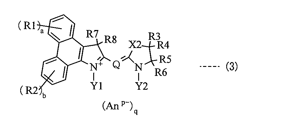
(R1およびR2は各々独立に水酸基、ニトロ基、シアノ基あるいはハロゲン原子、またはアルキル基、アルコキシ基、アリール基、アリールアルキル基あるいはそれらの誘導体であり、aおよびbは各々独立に0~4の整数である。R3~R6は各々独立に水素原子、水酸基、ニトロ基、シアノ基あるいはハロゲン原子、またはアルキル基、アルコキシ基、アリール基、アリールアルキル基あるいはそれらの誘導体であり、R3およびR4のうちの少なくとも一方とR5およびR6のうちの少なくとも一方とはそれぞれ脱離して二重結合を形成してもよいし、それぞれ連結して環構造を形成してもよい。X2は-C(R10)(R11)-で表される基、-N(R12)-で表される基、硫黄原子、酸素原子、セレン原子あるいはテルル原子である。R7、R8、R10およびR11は各々独立に水素原子あるいは上記した式(2)に示した基、または式(2)に示した基に該当するものを除く、アルキル基、アルコキシ基、アリール基、アリールアルキル基あるいはそれらの誘導体である。R12は各々独立に水素原子、水酸基、ニトロ基、シアノ基あるいはハロゲン原子、またはアルキル基、アルコキシ基、アリール基、アリールアルキル基あるいはそれらの誘導体である。Y1およびY2は各々独立にアンカー基、またはアルキル基、アルコキシ基、アリール基、アリールアルキル基あるいはそれらの誘導体であり、Y1およびY2のうちの少なくとも一方はアンカー基である。Qは炭素原子数1以上7以下のメチン鎖を骨格とする連結基である。Anp-はp価のアニオンであり、pは1あるいは2であり、qは電荷を中性に保つ係数である。)
(R1 and R2 are each independently a hydroxyl group, a nitro group, a cyano group or a halogen atom, or an alkyl group, an alkoxy group, an aryl group, an arylalkyl group or a derivative thereof, and a and b are each independently 0-4. R3 to R6 are each independently a hydrogen atom, a hydroxyl group, a nitro group, a cyano group or a halogen atom, or an alkyl group, an alkoxy group, an aryl group, an arylalkyl group or a derivative thereof, and among R3 and R4, And at least one of R5 and R6 may be eliminated to form a double bond, or may be linked to form a ring structure, and X2 is —C (R10) ( R11) — group, —N (R12) — group, sulfur atom, oxygen atom, selenium atom or tellurium source R7, R8, R10 and R11 are each independently an alkyl group, an alkoxy group, excluding a hydrogen atom or a group represented by the above formula (2), or a group corresponding to the group represented by the formula (2), An aryl group, an arylalkyl group or a derivative thereof, each R12 is independently a hydrogen atom, a hydroxyl group, a nitro group, a cyano group or a halogen atom, or an alkyl group, an alkoxy group, an aryl group, an arylalkyl group or a derivative thereof; Y1 and Y2 are each independently an anchor group, an alkyl group, an alkoxy group, an aryl group, an arylalkyl group or a derivative thereof, and at least one of Y1 and Y2 is an anchor group, Q is a carbon atom having 1 to 7 of the following methine chain is a linking group as a skeleton .An p-p-valent anion There, p is 1 or 2, q is a coefficient to maintain neutral electric charge.)
式(3)に示した化合物では、上記と同様の理由から、R7、R8、R10およびR11のうちの少なくとも1つが立体的に嵩高い基であることが好ましく、式(2)で表される基であることが好ましい。また、X2は、上記と同様の理由から-C(R10)(R11)-で表される基であることが好ましい。さらに、式(3)に示した化合物では、R3およびR4のうちの一方とR5およびR6のうちの一方との脱離により二重結合が形成されると共に、脱離していないR3およびR4のうちの他方とR5およびR6のうちの他方との連結により環構造が形成されているのが好ましい。担持体に対する電子注入効率がより良好となるため、より高い効果が得られるからである。また、Y1およびY2の双方がアンカー基であることが好ましく、アンカー基は、-CH2-CH2-C(=O)-OHで表される基あるいは-CH2 -CH2 -C(=O)-O-で表される基であるのが好ましい。さらに、Qは、メチン鎖骨格にシアノ基が導入された連結基であることが好ましい。いずれも上記と同様の理由からである。
In the compound represented by formula (3), for the same reason as described above, at least one of R7, R8, R10 and R11 is preferably a sterically bulky group, and is represented by formula (2). A group is preferred. X2 is preferably a group represented by -C (R10) (R11)-for the same reason as described above. Further, in the compound represented by the formula (3), a double bond is formed by elimination of one of R3 and R4 and one of R5 and R6, and among R3 and R4 which are not eliminated. A ring structure is preferably formed by linking the other of R5 and the other of R5 and R6. This is because the electron injection efficiency with respect to the carrier becomes better, and a higher effect can be obtained. Both Y1 and Y2 are preferably anchor groups, and the anchor group is a group represented by —CH 2 —CH 2 —C (═O) —OH or —CH 2 —CH 2 —C (= A group represented by O) —O 2 — is preferable. Furthermore, Q is preferably a linking group having a cyano group introduced into the methine chain skeleton. Both are for the same reason as above.
式(3)に示した化合物としては、X2が-C(R10)(R11)-で表される基であると共に、R3~R6の脱離および連結により環構造が形成された式(4)で表される構造を有する化合物(以下、式(4)に示した化合物という)であることが好ましい。X2が-C(R10)(R11)-で表される基であることにより、会合体抑制作用が高くなり、R3~R6の脱離および連結により環構造が形成されることにより、担持体に対する電子注入効率が高くなるからである。式(4)中で説明したR1、R2、R7、R8、R10、R11、Y1、Y2および(Anp-)qとしては、式(3)中のR1、R2、R7、R8、R10、R11、Y1、Y2および(Anp-)qと同様のものが挙げられる。
The compound represented by the formula (3) is a compound represented by the formula (4) in which X2 is a group represented by —C (R10) (R11) — and a ring structure is formed by elimination and connection of R3 to R6. It is preferable that it is a compound (henceforth the compound shown to Formula (4)) which has a structure represented by these. When X2 is a group represented by —C (R10) (R11) —, the aggregate inhibitory action is enhanced, and a ring structure is formed by the elimination and linking of R3 to R6, so that This is because the electron injection efficiency is increased. R1, R2, R7, R8, R10, R11, Y1, Y2 and (An p− ) q described in formula (4) are R1, R2, R7, R8, R10, R11 in formula (3). , Y1, Y2 and (An p- ) q are the same.

(R1およびR2は各々独立に水酸基、ニトロ基、シアノ基あるいはハロゲン原子、またはアルキル基、アルコキシ基、アリール基、アリールアルキル基あるいはそれらの誘導体であり、aおよびbは各々独立に0~4の整数である。R7、R8、R10およびR11は各々独立に水素原子あるいは上記した式(2)に示した基、または式(2)に示した基に該当するものを除く、アルキル基、アルコキシ基、アリール基、アリールアルキル基あるいはそれらの誘導体である。環Aはベンゼン環、ナフタレン環、フェナンスレン環あるいはそれらの誘導体である。Y1およびY2は各々独立にアンカー基、またはアルキル基、アルコキシ基、アリール基、アリールアルキル基あるいはそれらの誘導体であり、Y1およびY2のうちの少なくとも一方はアンカー基である。Qは炭素原子数1以上7以下のメチン鎖を骨格とする連結基である。Anp-はp価のアニオンであり、pは1あるいは2であり、qは電荷を中性に保つ係数である。)
(R1 and R2 are each independently a hydroxyl group, a nitro group, a cyano group or a halogen atom, or an alkyl group, an alkoxy group, an aryl group, an arylalkyl group or a derivative thereof, and a and b are each independently 0-4. R7, R8, R10 and R11 are each independently a hydrogen atom, an alkyl group or an alkoxy group other than those represented by the group represented by the formula (2) or the group represented by the formula (2). A ring is a benzene ring, naphthalene ring, phenanthrene ring or a derivative thereof Y1 and Y2 are each independently an anchor group, an alkyl group, an alkoxy group, an aryl group, an aryl group, an arylalkyl group, or a derivative thereof. A group, an arylalkyl group or a derivative thereof, and at least one of Y1 and Y2 One is an anchor group .Q is .An p-is a linkage group that has a methine chain having 1 to 7 carbon atoms as a skeleton is a p-valent anion, p is 1 or 2, q is the charge Is a neutral coefficient.)
式(4)中で説明した環Aは、ベンゼン環、ナフタレン環あるいはフェナンスレン環の骨格を有していれば任意であり、1あるいは2以上の置換基を有していてもよい。環Aがナフタレン環あるいはフェナンスレン環である場合には、その環が5員複素環と縮合する位置も任意である。環Aに導入される置換基は任意であり、例えば、メチル基、エチル基あるいはブチル基などのアルキル基、メトキシ基あるいはエトキシ基などのアルコキシ基、フェニル基などのアリール基、ベンジル基などのフェニルアルキル基またはそれらの誘導体などが挙げられる。
Ring A described in formula (4) is optional as long as it has a benzene ring, naphthalene ring or phenanthrene ring skeleton, and may have one or more substituents. When ring A is a naphthalene ring or a phenanthrene ring, the position at which the ring is condensed with a 5-membered heterocyclic ring is also arbitrary. The substituent introduced into ring A is arbitrary, for example, an alkyl group such as a methyl group, an ethyl group or a butyl group, an alkoxy group such as a methoxy group or an ethoxy group, an aryl group such as a phenyl group, or a phenyl group such as a benzyl group Examples thereof include alkyl groups or derivatives thereof.
式(4)で示した化合物においても、上記と同様の理由から、R7、R8、R10およびR11のうちの少なくとも1つが立体的に嵩高い基であることが好ましく、具体的には式(2)で表される基であることが好ましい。また、Y1およびY2の双方がアンカー基であることが好ましく、アンカー基は、-CH2-CH2-C(=O)-OHで表される基あるいは-CH2 -CH2 -C(=O)-O-で表される基であるのが好ましい。さらに、Qは、メチン鎖骨格にシアノ基が導入された連結基であることが好ましい。いずれも上記と同様の理由からである。
Also in the compound represented by the formula (4), for the same reason as described above, at least one of R7, R8, R10 and R11 is preferably a sterically bulky group. It is preferable that it is group represented by. Both Y1 and Y2 are preferably anchor groups, and the anchor group is a group represented by —CH 2 —CH 2 —C (═O) —OH or —CH 2 —CH 2 —C (= A group represented by O) —O 2 — is preferable. Furthermore, Q is preferably a linking group having a cyano group introduced into the methine chain skeleton. Both are for the same reason as above.
式(4)に示した化合物としては、環Aがフェナンスレン環あるいはその誘導体である式(5)に示した構造を有する化合物(以下、式(5)に示した化合物という)が好ましい。メチン鎖(Q)の両端に結合した複素環骨格の双方がフェナンスレン骨格を含むことにより、より広い波長域の光を吸収しやすくなるからである。式(5)中で説明したR1、R2、R7、R8、R10、R11、Y1、Y2および(Anp-)qとしては、式(4)中のR1、R2、R7、R8、R10、R11、Y1、Y2および(Anp-)qと同様のものが挙げられる。また、式(5)中で説明したR13およびR14としては、R1およびR2と同様のものが挙げられる。
As the compound represented by the formula (4), a compound having a structure represented by the formula (5) in which the ring A is a phenanthrene ring or a derivative thereof (hereinafter referred to as a compound represented by the formula (5)) is preferable. This is because when both of the heterocyclic skeletons bonded to both ends of the methine chain (Q) contain a phenanthrene skeleton, light in a wider wavelength range is easily absorbed. R1, R2, R7, R8, R10, R11, Y1, Y2 and (An p− ) q described in the formula (5) are R1, R2, R7, R8, R10, R11 in the formula (4). , Y1, Y2 and (An p− ) q are the same. Moreover, as R13 and R14 demonstrated in Formula (5), the thing similar to R1 and R2 is mentioned.

(R1、R2、R13およびR14は各々独立に水酸基、ニトロ基、シアノ基あるいはハロゲン原子、またはアルキル基、アルコキシ基、アリール基、アリールアルキル基あるいはそれらの誘導体であり、a~dは各々独立に0~4の整数である。R7、R8、R10およびR11は各々独立に水素原子あるいは上記した式(2)に示した基、または式(2)に示した基に該当するものを除く、アルキル基、アルコキシ基、アリール基、アリールアルキル基あるいはそれらの誘導体である。Y1およびY2は各々独立にアンカー基、またはアルキル基、アルコキシ基、アリール基、アリールアルキル基あるいはそれらの誘導体であり、Y1およびY2のうちの少なくとも一方はアンカー基である。Qは炭素原子数1以上7以下のメチン鎖を骨格とする連結基である。Anp-はp価のアニオンであり、pは1あるいは2であり、qは電荷を中性に保つ係数である。)
(R1, R2, R13 and R14 are each independently a hydroxyl group, a nitro group, a cyano group or a halogen atom, or an alkyl group, an alkoxy group, an aryl group, an arylalkyl group or a derivative thereof; R is an integer of 0 to 4. R7, R8, R10 and R11 are each independently an alkyl other than a hydrogen atom or a group represented by the above formula (2) or a group represented by the formula (2) A group, an alkoxy group, an aryl group, an arylalkyl group or a derivative thereof Y1 and Y2 are each independently an anchor group, or an alkyl group, an alkoxy group, an aryl group, an arylalkyl group, or a derivative thereof; At least one of Y2 is an anchor group, Q is a methine chain having 1 to 7 carbon atoms. A is .An p-linking group and a p-valent anion, p is 1 or 2, q is a coefficient to maintain neutral electric charge.)
式(5)に示した化合物においても、上記と同様の理由から、R7、R8、R10およびR11のうちの少なくとも1つが立体的に嵩高い基であることが好ましく、式(2)で表される基であることが好ましい。また、Y1およびY2の双方がアンカー基であることが好ましく、アンカー基は、-CH2-CH2-C(=O)-OHで表される基あるいは-CH2 -CH2 -C(=O)-O-で表される基であるのが好ましい。さらに、Qは、メチン鎖骨格にシアノ基が導入された連結基であることが好ましい。いずれも上記と同様の理由からである。
Also in the compound represented by the formula (5), for the same reason as described above, at least one of R7, R8, R10 and R11 is preferably a sterically bulky group, and is represented by the formula (2). It is preferably a group. Both Y1 and Y2 are preferably anchor groups, and the anchor group is a group represented by —CH 2 —CH 2 —C (═O) —OH or —CH 2 —CH 2 —C (= A group represented by O) —O 2 — is preferable. Furthermore, Q is preferably a linking group having a cyano group introduced into the methine chain skeleton. Both are for the same reason as above.
上記した式(3)~式(5)に示した化合物を含む式(1)に示したシアニン化合物としては、式(8)~式(283)で表される構造部を有する化合物などが挙げられる。なお、式(8)~式(283)に示した構造部は、式(1)中のAnp-を含まない部分(カチオン部分)を表しており、これらの構造では、例えば、上記した1価あるいは2価のアニオンであれば、任意に組み合わせることが可能であり、その他のアニオンであっても同様である。また、これらの構造部では、例えば、酸性基がイオン化して内部塩を形成することもできる。
Examples of the cyanine compound represented by the formula (1) including the compounds represented by the above formulas (3) to (5) include compounds having a structural part represented by the formulas (8) to (283). It is done. Note that the structural parts shown in the formulas (8) to (283) represent a part (cation part) that does not contain An p- in the formula (1). In these structures, for example, the above-described 1 Any anionic or divalent anion can be combined, and the same applies to other anions. In these structural parts, for example, an acidic group can be ionized to form an internal salt.
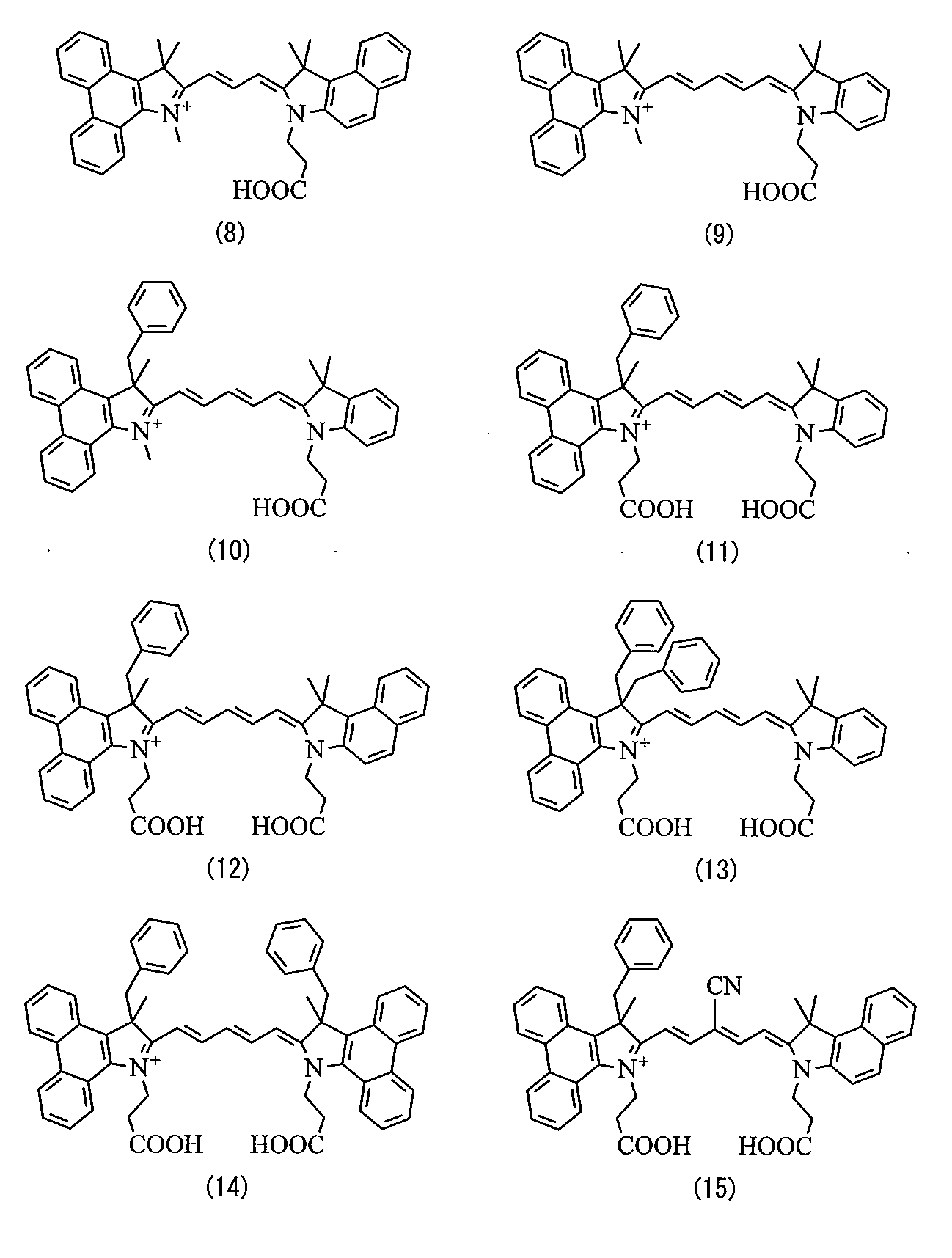
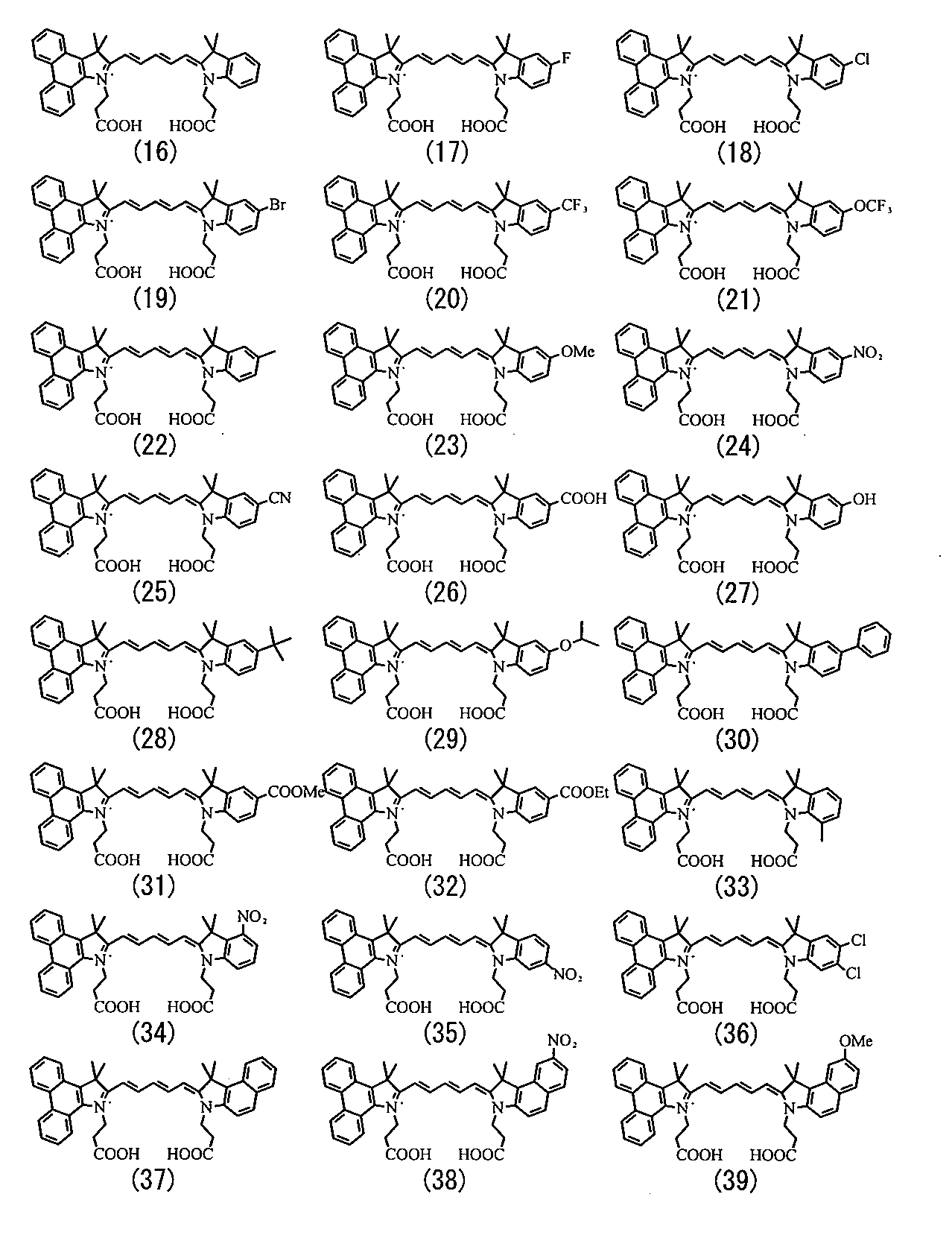

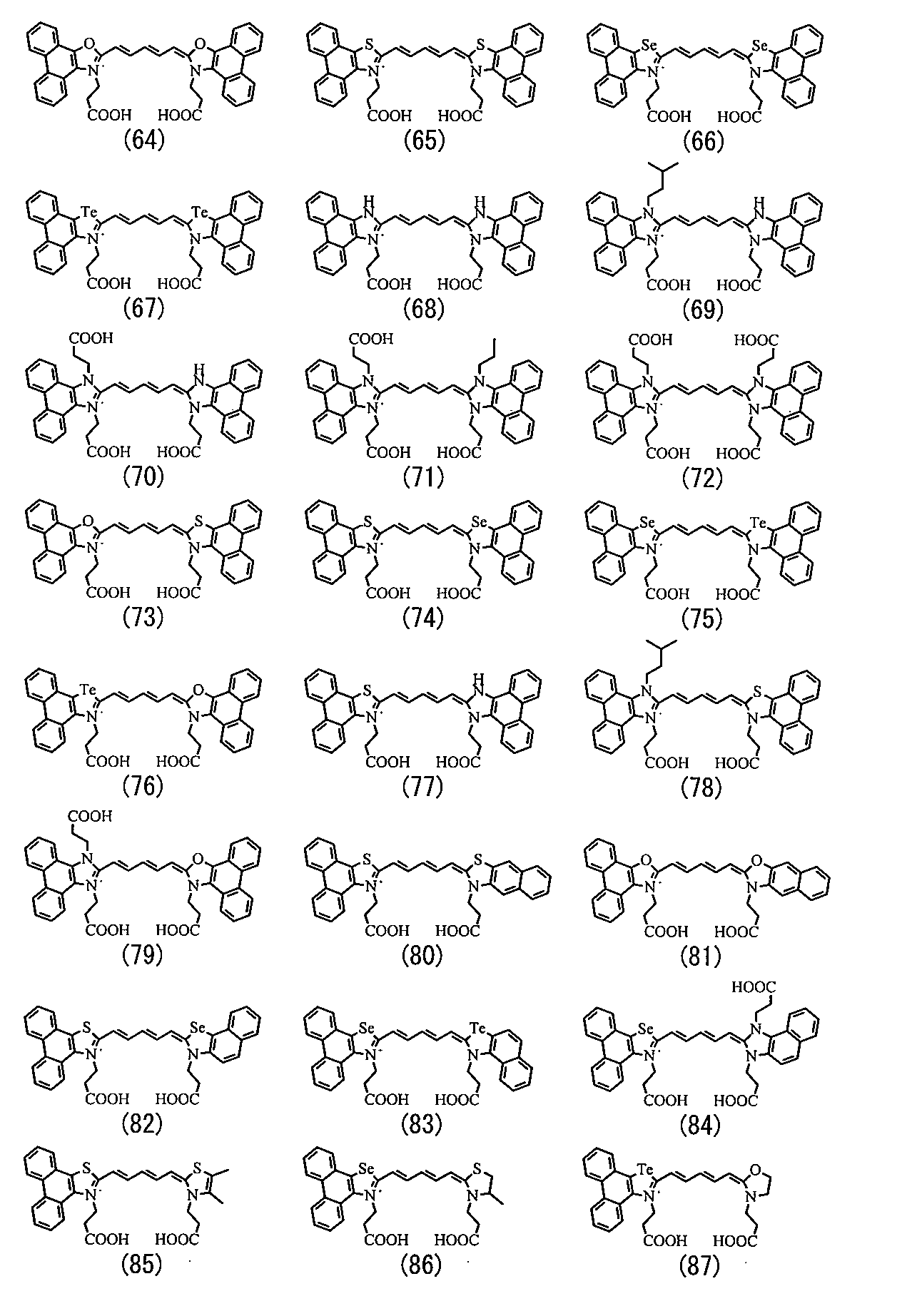
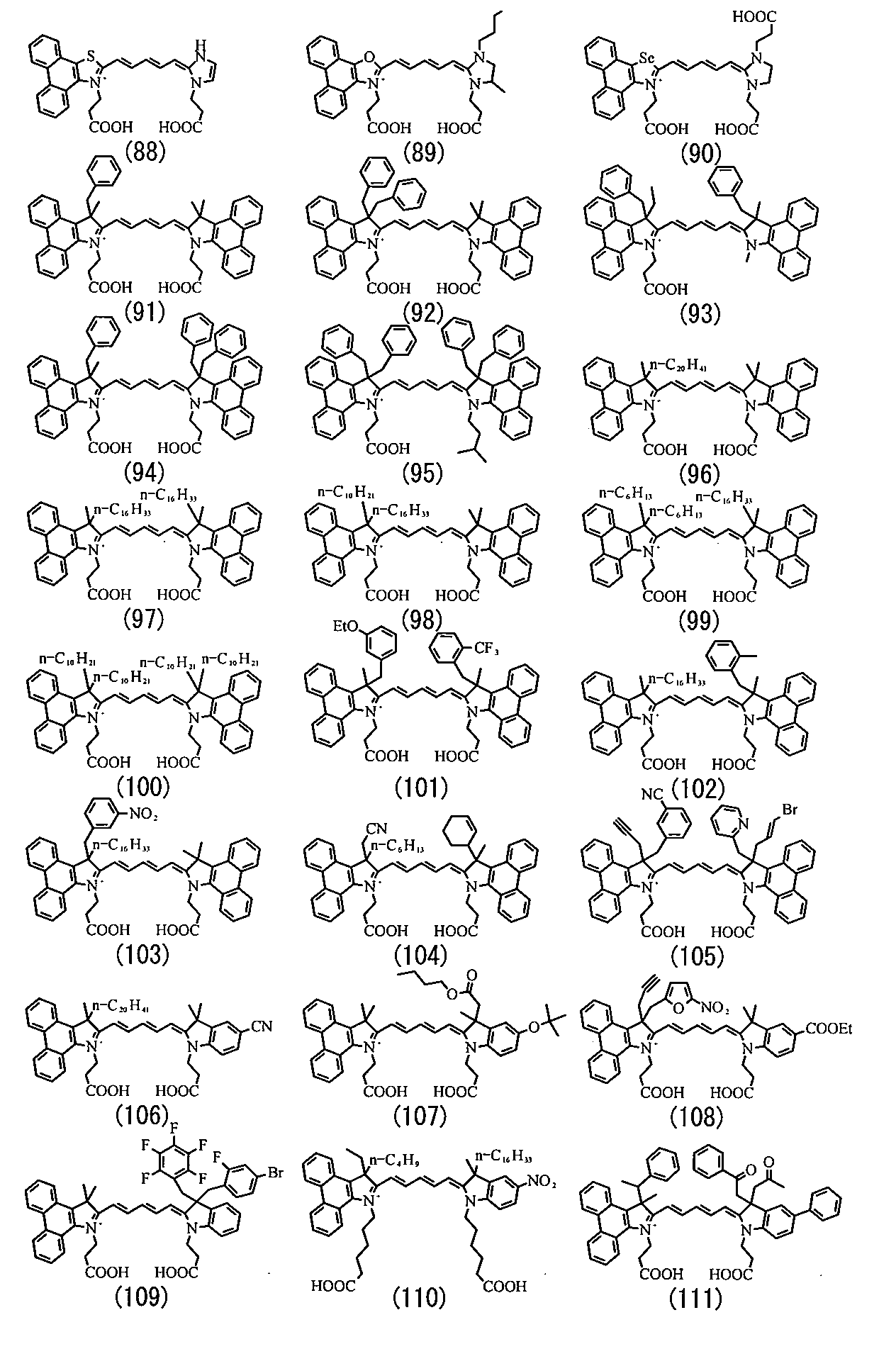
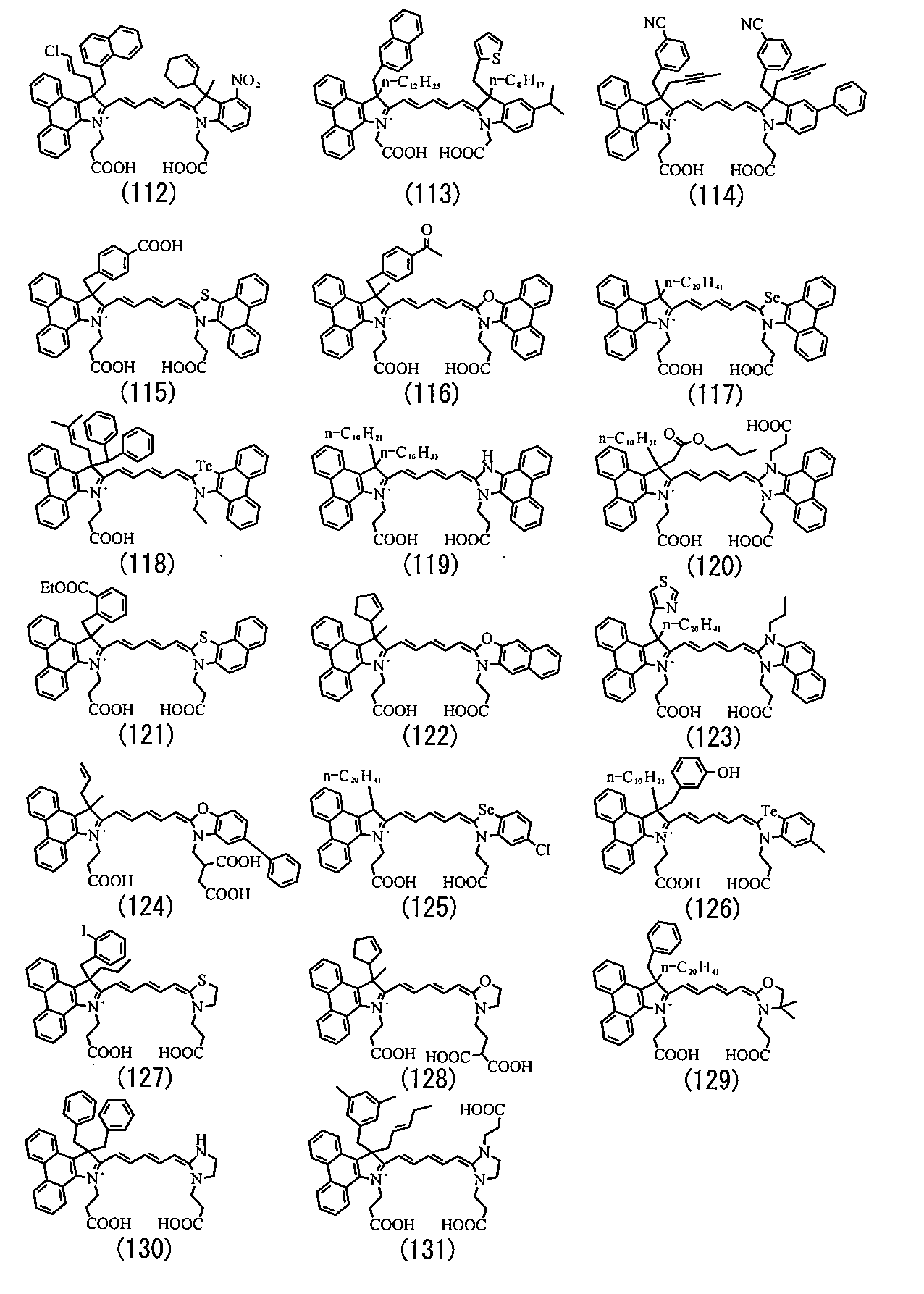


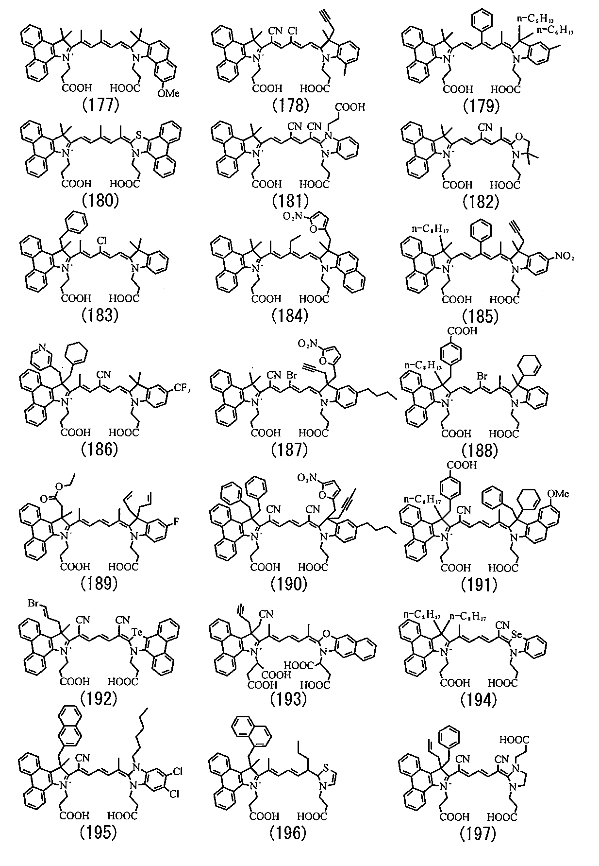

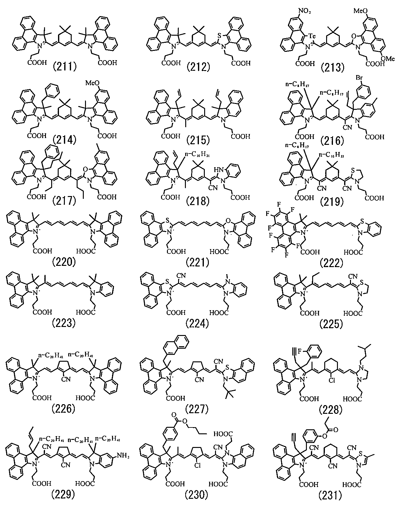


なお、式(1)に示したシアニン構造を有する化合物であれば、式(8)~式(283)に示した構造部を含む化合物に限定されないことは、言うまでもなく、このことは式(3)~式(5)についても同様である。
Needless to say, the compound having the cyanine structure represented by the formula (1) is not limited to the compound including the structural portion represented by the formulas (8) to (283). The same applies to the formulas (5) to (5).
次に、式(1)に示したシアニン化合物の合成方法の具体例について、式(I)~式(V)で表される化学反応式を参照して説明する。上記した式(1)に示したシアニン化合物は、例えば、以下の2つの方法により合成することができる。
Next, specific examples of the method for synthesizing the cyanine compound represented by the formula (1) will be described with reference to chemical reaction formulas represented by the formulas (I) to (V). The cyanine compound represented by the above formula (1) can be synthesized, for example, by the following two methods.
第1の合成方法では、式(1)中のQに含まれるメチン鎖骨格の炭素原子数が1の化合物を合成する。最初に、式(1)中の複素環骨格が含む5員環骨格中の窒素原子に対して、Y1あるいはY2となる基を導入する。具体的には、式(I)の化学反応式に示したように、式(284)で表される複素環骨格を有する化合物と、式(285)で表される化合物と、必要に応じてAnp-となる所定量のアニオンとを混合して反応させることにより、式(286)で表される4級アンモニウム塩を合成する。式(284)で表される複素環骨格を有する化合物は、のちに式(1)中のメチン鎖骨格(Q)の両端に結合する骨格部分を含むものである。また、式(285)に示した化合物は、R51が脱離することにより、式(286)中の5員環部分に含まれる窒素原子に導入されてY1となる部分を含むものである。なお、式(I)中では、メチン鎖骨格の両端に結合する複素環骨格のうちのフェナンスレン骨格を含む部分の合成について示しているが、他方の複素環骨格部分についても同様にして合成できる。
In the first synthesis method, a compound having 1 carbon atom in the methine chain skeleton contained in Q in the formula (1) is synthesized. First, a group that becomes Y1 or Y2 is introduced to the nitrogen atom in the 5-membered ring skeleton included in the heterocyclic skeleton in the formula (1). Specifically, as shown in the chemical reaction formula of the formula (I), a compound having a heterocyclic skeleton represented by the formula (284), a compound represented by the formula (285), and as necessary A quaternary ammonium salt represented by the formula (286) is synthesized by mixing and reacting with a predetermined amount of anion which becomes An p- . The compound having a heterocyclic skeleton represented by the formula (284) includes a skeleton portion that is bonded to both ends of the methine chain skeleton (Q) in the formula (1). In addition, the compound represented by the formula (285) includes a portion which is introduced into a nitrogen atom contained in the 5-membered ring portion in the formula (286) and becomes Y1 when R51 is eliminated. In the formula (I), the synthesis of a portion containing a phenanthrene skeleton in the heterocyclic skeleton bonded to both ends of the methine chain skeleton is shown, but the other heterocyclic skeleton portion can be synthesized in the same manner.

(R1、R2、a、b、X1およびY1は、式(1)中で説明したR1、R2、a、b、X1およびY1のそれぞれと同様のものであり、R50は水素原子あるいは1価の置換基であり、式(1)中においてQのメチン鎖骨格を構成する炭素原子に対して導入されることになる1価の基である。R51はハロゲン原子などの脱離基である。Anp-はp価のアニオンであり、pは1あるいは2であり、qは式(286)の化合物において電荷を中性に保つ係数である。)
(R1, R2, a, b, X1 and Y1 are the same as R1, R2, a, b, X1 and Y1 described in formula (1), and R50 is a hydrogen atom or a monovalent group. A substituent, which is a monovalent group to be introduced into the carbon atom constituting the methine chain skeleton of Q in formula (1), R51 is a leaving group such as a halogen atom. p- is a p-valent anion, p is 1 or 2, and q is a coefficient that keeps the charge neutral in the compound of formula (286).
次に、式(II)の化学反応式に示したように、式(286)に示した4級アンモニウム塩と、脱離基(R52)を有する式(287)で表される4級アンモニウム塩とを塩基(Base)存在下で反応させる。これにより、最終生成物として式(1)中のQに含まれるメチン鎖骨格の炭素原子数が1であるシアニン化合物(式(288))が合成される。なお、式(287)に示した脱離基R52を有する4級アンモニウム塩は、例えば、式(286)に示した4級アンモニウム塩と同様にして合成することができる。
Next, as shown in the chemical reaction formula of the formula (II), the quaternary ammonium salt represented by the formula (286) and the quaternary ammonium salt represented by the formula (287) having a leaving group (R52). Are reacted in the presence of a base. As a result, a cyanine compound (formula (288)) having 1 carbon atom in the methine chain skeleton contained in Q in formula (1) is synthesized as the final product. The quaternary ammonium salt having the leaving group R52 represented by the formula (287) can be synthesized, for example, in the same manner as the quaternary ammonium salt represented by the formula (286).
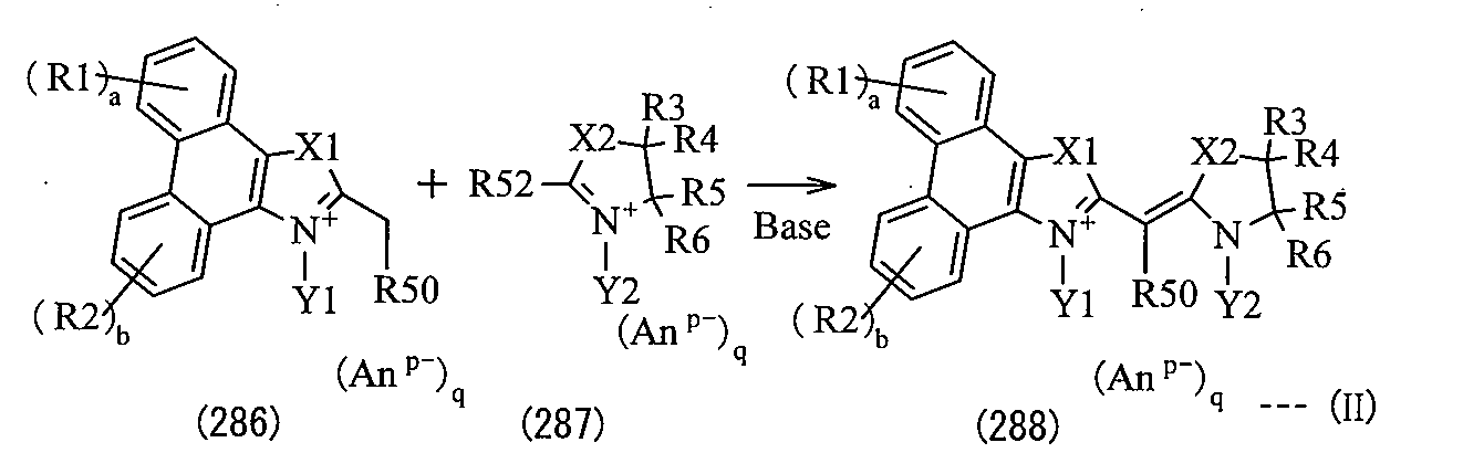
(R1~R6、a,b、X1,X2およびY1,Y2は式(1)中で説明したR1~R6、a,b、X1,X2およびY1,Y2と同様のものである。Anp-はp価のアニオンであり、pは1あるいは2であり、qは式(286)~式(288)に示した各式の化合物において、電荷を中性に保つ係数である。R50は水素原子あるいは1価の置換基であり、R52は-S-R100で表される基あるいは-CH=N-OHなどの脱離基であり、R100はメチル基などのアルキル基である。)
(R1 ~ R6, a, b , X1, X2 and Y1, Y2 are the same as R1 ~ R6, a, b, X1, X2 and Y1, Y2 explained in Formula (1) .An p- Is a p-valent anion, p is 1 or 2, and q is a coefficient for maintaining a neutral charge in the compounds of the formulas (286) to (288) R50 is a hydrogen atom Or a monovalent substituent, R52 is a group represented by —S—R100 or a leaving group such as —CH═N—OH, and R100 is an alkyl group such as a methyl group.)
第2の合成方法では、式(1)中のQに含まれるメチン鎖骨格の炭素原子数が1よりも大きい化合物を合成する。最初に、式(I)の化学反応式に示した手順と同様にして、式(286)に示した4級アンモニウム塩を合成する。次に、式(III)の化学反応式に示したように、式(286)に示した4級アンモニウム塩と、ブリッジ剤として式(289)で表される化合物とを混合して反応させることにより、式(290)で表されるシアニン中間体を合成する。最後に、式(IV)の示した化学反応式に示したように、式(290)に示したシアニン中間体と、式(286)に示した4級アンモニウム塩の合成経路(式(I))と同様の経路を経て合成された式(291)に示した4級アンモニウム塩とを、塩基および無水酢酸((CH3CO)2O)存在下で反応させる。これにより、最終生成物として式(1)中のQのメチン鎖骨格の炭素原子数が1より大きいシアニン化合物(式(292))が合成される。式(III)の化学反応式において、ブリッジ剤として用いた式(289)に示した化合物としては、例えば、式(289-1)~式(289-4)で表される化合物が挙げられ、その他のブリッジ剤としては、例えば、式(293)~式(295)で表される化合物が挙げられる。
In the second synthesis method, a compound in which the number of carbon atoms in the methine chain skeleton contained in Q in formula (1) is larger than 1 is synthesized. First, a quaternary ammonium salt represented by the formula (286) is synthesized in the same manner as the procedure represented by the chemical reaction formula of the formula (I). Next, as shown in the chemical reaction formula of the formula (III), the quaternary ammonium salt shown in the formula (286) and the compound represented by the formula (289) as a bridging agent are mixed and reacted. To synthesize a cyanine intermediate represented by the formula (290). Finally, as shown in the chemical reaction formula shown by the formula (IV), the synthesis route of the cyanine intermediate shown in the formula (290) and the quaternary ammonium salt shown in the formula (286) (formula (I) ) And a quaternary ammonium salt represented by the formula (291) synthesized via the same route as in the presence of a base and acetic anhydride ((CH 3 CO) 2 O). As a result, a cyanine compound (formula (292)) in which the number of carbon atoms in the methine chain skeleton of Q in formula (1) is larger than 1 is synthesized as a final product. Examples of the compound represented by the formula (289) used as the bridging agent in the chemical reaction formula of the formula (III) include compounds represented by the formulas (289-1) to (289-4), Examples of other bridging agents include compounds represented by formulas (293) to (295).
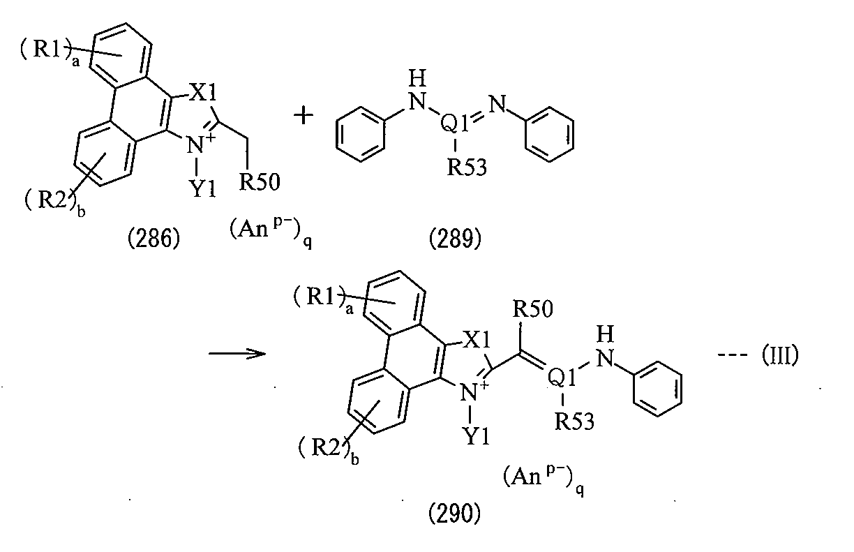
(R1,R2、a,b、X1およびY1は式(1)中で説明したR1,R2、a,b、X1およびY1と同様のものである。Anp-はp価のアニオンであり、pは1あるいは2であり、qは式(286)および式(290)に示した各式の化合物において、電荷を中性に保つ係数である。R50およびR53は水素原子あるいは1価の置換基である。Q1は炭素原子数1以上5以下のメチン鎖を骨格とする連結基である。)
(R1, R2, a, b, X1 and Y1 are the same as R1, R2, a, b, X1 and Y1 described in formula (1). An p- is a p-valent anion; p is 1 or 2, and q is a coefficient for keeping the charge neutral in the compounds of the formulas (286) and (290) R50 and R53 are hydrogen atoms or monovalent substituents Q1 is a linking group having a methine chain having 1 to 5 carbon atoms as a skeleton.)

(R1~R6、a,b、X1,X2およびY1,Y2は式(1)中で説明したR1~R6、a,b、X1,X2およびY1,Y2と同様のものである。Anp-はp価のアニオンであり、pは1あるいは2であり、qは式(290)~式(292)に示した各式の化合物において、電荷を中性に保つ係数である。R50、R53およびR54は水素原子あるいは1価の置換基である。Q1は炭素原子数1以上5以下のメチン鎖を骨格とする連結基である。)
(R1 ~ R6, a, b , X1, X2 and Y1, Y2 are the same as R1 ~ R6, a, b, X1, X2 and Y1, Y2 explained in Formula (1) .An p- Is a p-valent anion, p is 1 or 2, and q is a coefficient for maintaining a neutral charge in the compounds of the formulas (290) to (292) R50, R53 and R54 is a hydrogen atom or a monovalent substituent, and Q1 is a linking group having a methine chain having 1 to 5 carbon atoms as a skeleton.

(R53は水素原子あるいは置換基である。)
(R53 is a hydrogen atom or a substituent.)

なお、第2の合成方法では、式(III )および式(IV)の化学反応式に示したように式(286)に示した4級アンモニウム塩等を用いて式(290)に示したシアニン中間体を合成するように、2段階に分けて合成した。しかしながら、最終生成物においてメチン鎖の両端に結合する複素環骨格を含む部分が同じ構造を有していれば、例えば、式(V)の化学反応式に示したように1段階で反応させて最終生成物(式(296))を得るようにしてもよい。この場合には、式(286)に示した4級アンモニウム塩と、式(289)に示したブリッジ剤とを、塩基および無水酢酸((CH3CO)2O)存在下で反応させる。
In the second synthesis method, as shown in the chemical reaction formulas of the formulas (III) and (IV), the cyanine represented by the formula (290) using the quaternary ammonium salt shown in the formula (286) or the like. In order to synthesize the intermediate, it was synthesized in two steps. However, if the final product contains a heterocyclic skeleton bonded to both ends of the methine chain and has the same structure, for example, as shown in the chemical reaction formula of the formula (V), the reaction is performed in one step. The final product (formula (296)) may be obtained. In this case, the quaternary ammonium salt represented by the formula (286) and the bridging agent represented by the formula (289) are reacted in the presence of a base and acetic anhydride ((CH 3 CO) 2 O).
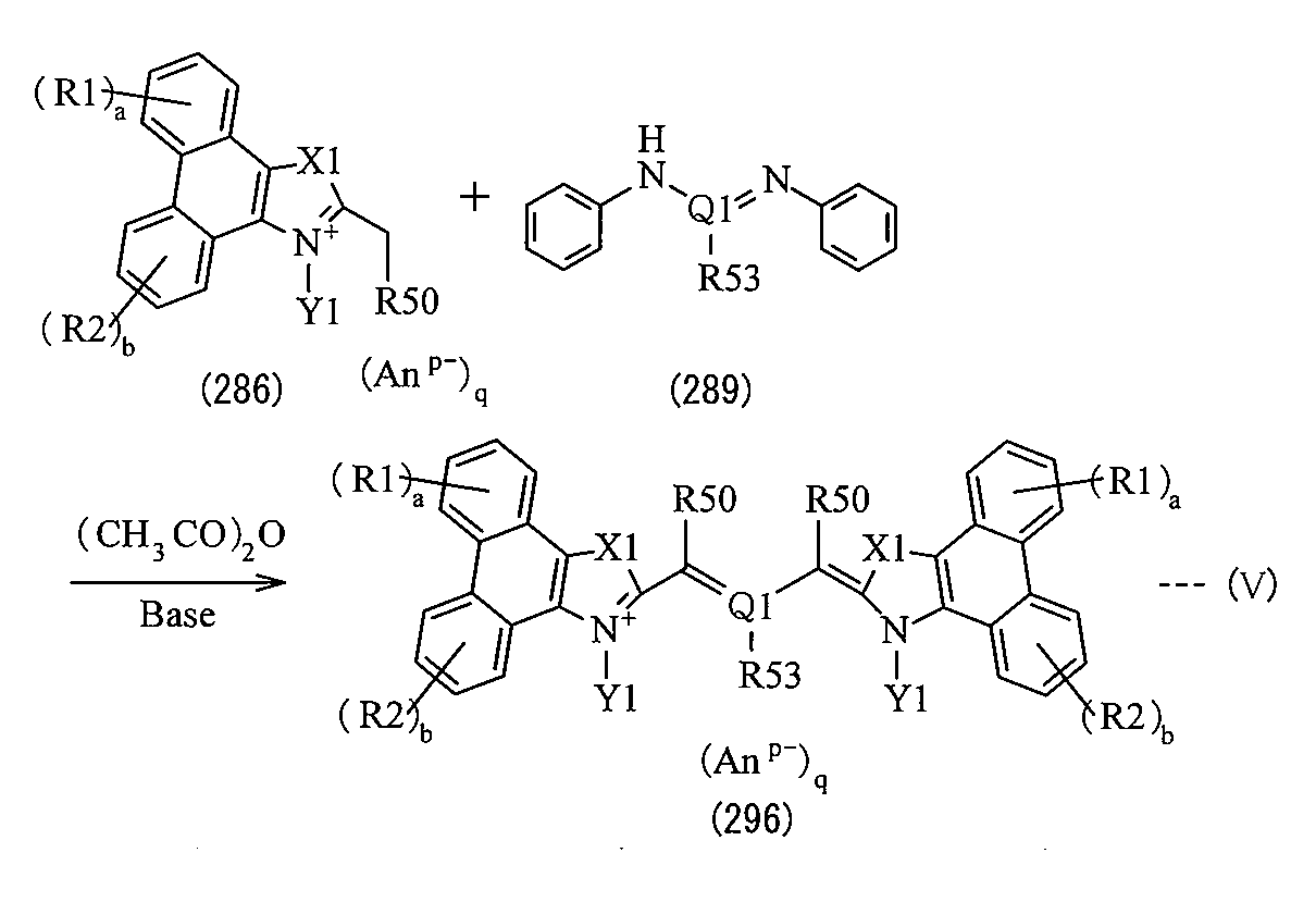
(R1,R2、a,b、X1およびY1は式(1)中で説明したR1,R2、a,b、X1およびY1と同様のものである。Anp-はp価のアニオンであり、pは1あるいは2であり、qは式(286)および式(296)に示した各式の化合物において、電荷を中性に保つ係数である。R50およびR53は水素原子あるいは1価の置換基である。Q1は炭素原子数1以上5以下のメチン鎖を骨格とする連結基である。)
(R1, R2, a, b, X1 and Y1 are the same as R1, R2, a, b, X1 and Y1 described in formula (1). An p- is a p-valent anion; p is 1 or 2, and q is a coefficient for maintaining a neutral charge in the compounds of the formulas (286) and (296) R50 and R53 are hydrogen atoms or monovalent substituents Q1 is a linking group having a methine chain having 1 to 5 carbon atoms as a skeleton.)
本実施の形態に係る光電変換素子用色素では、式(1)に示したシアニン構造を有するので、その構造をもたない色素(例えば、フェナンスレン骨格の代わりにベンゼン骨格あるいはナフタレン骨格を含むシアニン化合物)と比較して、紫外光域から近赤外光域のうちの広い波長域の光を吸収して励起される。その上、担持体に担持された状態において、その担持体に対して効率よく電子を注入することができる。よって、光電変換素子に用いれば、照射された光量に対して色素から担持体への電子注入量が高くなり、IPCE(IncidentPhotonsto Current conversion Efficiency)が向上し、変換効率を向上させることができる。なお、IPCEとは、光電変換素子において照射された光の光子数に対する光電流の電子数へ変換された割合を表すものであり、IPCE(%)=Isc×1240/λ×1/φ(式中、Iscは短絡電流であり、λは波長であり、φは入射光強度である。)により求められる。
Since the dye for photoelectric conversion elements according to this embodiment has the cyanine structure represented by the formula (1), the dye does not have the structure (for example, a cyanine compound containing a benzene skeleton or a naphthalene skeleton instead of a phenanthrene skeleton). ) Is absorbed by absorbing light in a wide wavelength region from the ultraviolet light region to the near infrared light region. In addition, electrons can be efficiently injected into the carrier while being carried on the carrier. Therefore, when used for a photoelectric conversion element, the amount of electrons injected from the dye to the carrier increases with respect to the amount of light irradiated, IPCE (Incident Photonsto Current Current conversion Efficiency) is improved, and conversion efficiency can be improved. Note that IPCE represents the ratio of photocurrent converted to the number of electrons with respect to the number of photons irradiated in the photoelectric conversion element, and IPCE (%) = Isc × 1240 / λ × 1 / φ (formula Where Isc is a short circuit current, λ is a wavelength, and φ is an incident light intensity.
この場合、式(1)に示したシアニン構造は、式(3)に示した構造でもよいし、式(4)に示した構造でもよいし、式(5)に示した構造であってもよい。これにより、分子全体として平面性が低下するため、会合体の形成が抑制される。よって、光電変換素子に用いた場合に、担持体に担持された色素全体における光電変換に寄与しにくい会合体の割合が低下することにより、高い変換効率を得ることができる。特に、式(1)に示したシアニン構造が式(5)に示した構造であれば、メチン鎖骨格の両端に導入された複素環骨格の双方がフェナンスレン骨格を含むことになるため、担持体に対してより効率よく電子が注入され、より高い効果が得られやすくなる。
In this case, the cyanine structure shown in Formula (1) may be the structure shown in Formula (3), the structure shown in Formula (4), or the structure shown in Formula (5). Good. Thereby, since planarity falls as a whole molecule | numerator, formation of an aggregate is suppressed. Therefore, when used in a photoelectric conversion element, a high conversion efficiency can be obtained by reducing the proportion of aggregates that hardly contribute to photoelectric conversion in the entire dye supported on the support. In particular, if the cyanine structure shown in Formula (1) is the structure shown in Formula (5), both heterocyclic skeletons introduced at both ends of the methine chain skeleton contain phenanthrene skeletons. In contrast, electrons are injected more efficiently, and a higher effect is easily obtained.
また、特に、式(1)あるいは式(3)~式(5)に示したR7、R8、R10およびR11のうちの少なくとも1つが上記した式(2)に示した基であれば、分子全体としての平面性がより低くなるため、光電変換素子に用いた場合に、変換効率をより向上させることができる。また、式(1)あるいは式(3)~式(5)に示したY1およびY2の双方がアンカー基であれば、担持体から剥離しにくくなるため、光電変換素子に用いた場合に、素子全体として吸収した光量に対して担持体への電子注入量が高くなり、より高い変換効率を得ることができる。
In particular, if at least one of R7, R8, R10 and R11 shown in Formula (1) or Formula (3) to Formula (5) is a group shown in Formula (2) above, the entire molecule Therefore, the conversion efficiency can be further improved when used in a photoelectric conversion element. In addition, when both Y1 and Y2 shown in the formula (1) or the formulas (3) to (5) are anchor groups, it is difficult to peel off from the carrier, so that when used in a photoelectric conversion element, the element The amount of electrons injected into the carrier increases with respect to the amount of light absorbed as a whole, and higher conversion efficiency can be obtained.
さらに、式(1)あるいは式(3)~式(5)に示したQは、メチン鎖骨格にシアノ基が導入された連結基であれば、光電変換素子に用いた場合に、IV特性(電流電圧特性)の形状因子(FF;FillFactor)を向上させることができ、高い変換効率を得ることができる。
Furthermore, Q in the formula (1) or formulas (3) to (5) is a linking group in which a cyano group is introduced into the methine chain skeleton, and when used in a photoelectric conversion element, the IV characteristics ( The shape factor (FF; FillFactor) of current-voltage characteristics can be improved, and high conversion efficiency can be obtained.
次に、本実施の形態に係る光電変換素子用色素の使用例について説明する。
Next, a usage example of the photoelectric conversion element dye according to the present embodiment will be described.
図1は、光電変換素子の断面構成を模式的に表すものであり、図2は、図1に示した光電変換素子の主要部を抜粋および拡大して表すものである。図1および図2に示した光電変換素子は、いわゆる色素増感型太陽電池の主要部である。この光電変換素子は、作用電極10と対向電極20とが電解質含有層30を介して対向配置されたものであり、作用電極10および対向電極20のうちの少なくとも一方は、光透過性を有する電極である。
FIG. 1 schematically shows a cross-sectional configuration of a photoelectric conversion element, and FIG. 2 shows an extracted and enlarged main part of the photoelectric conversion element shown in FIG. The photoelectric conversion element shown in FIGS. 1 and 2 is a main part of a so-called dye-sensitized solar cell. In this photoelectric conversion element, the working electrode 10 and the counter electrode 20 are disposed to face each other with the electrolyte-containing layer 30 interposed therebetween, and at least one of the working electrode 10 and the counter electrode 20 is an electrode having optical transparency. It is.
作用電極10は、例えば、導電性基板11と、その一方の面(対向電極20の側の面)に設けられた金属酸化物半導体層12と、金属酸化物半導体層12を担持体として担持された色素13とを有している。作用電極10は、外部回路に対して、負極として機能するものである。導電性基板11は、例えば、絶縁性の基板11Aの表面に導電層11Bを設けたものである。
The working electrode 10 is, for example, supported on a conductive substrate 11, a metal oxide semiconductor layer 12 provided on one surface thereof (surface on the counter electrode 20 side), and the metal oxide semiconductor layer 12 as a carrier. Pigment 13. The working electrode 10 functions as a negative electrode for the external circuit. For example, the conductive substrate 11 is obtained by providing a conductive layer 11B on the surface of an insulating substrate 11A.
基板11Aの材料としては、例えば、ガラス、プラスチック、透明ポリマーフィルムなどの絶縁性材料が挙げられる。透明ポリマーフィルムとしては、例えば、テトラアセチルセルロース(TAC)、ポリエチレンテレフタレート(PET)、ポリエチレンナフタレート(PEN)、シンジオタクチックポリスチレン(SPS)、ポリフェニレンスルフィド(PPS)、ポリカーボネート(PC)、ポリアリレート(PAR)、ポリスルフォン(PSF)、ポリエステルスルフォン(PES)、ポリエーテルイミド(PEI)、環状ポリオレフィンあるいはブロム化フェノキシなどが挙げられる。
Examples of the material of the substrate 11A include insulating materials such as glass, plastic, and transparent polymer film. Examples of the transparent polymer film include tetraacetyl cellulose (TAC), polyethylene terephthalate (PET), polyethylene naphthalate (PEN), syndiotactic polystyrene (SPS), polyphenylene sulfide (PPS), polycarbonate (PC), polyarylate ( PAR), polysulfone (PSF), polyester sulfone (PES), polyetherimide (PEI), cyclic polyolefin or brominated phenoxy.
導電層11Bとしては、例えば、酸化インジウム、酸化スズ、インジウム-スズ複合酸化物(ITO)あるいは酸化スズにフッ素をドープしたもの(FTO:F-SnO2)などを含む導電性金属酸化物薄膜や、金(Au)、銀(Ag)あるいは白金(Pt)などを含む金属薄膜や、導電性高分子などで形成されたものなどが挙げられる。
Examples of the conductive layer 11B include a conductive metal oxide thin film including indium oxide, tin oxide, indium-tin composite oxide (ITO), or tin oxide doped with fluorine (FTO: F—SnO 2 ). , A metal thin film containing gold (Au), silver (Ag), platinum (Pt), or the like, or a conductive polymer or the like.
なお、導電性基板11は、例えば、導電性を有する材料によって単層構造となるように構成されていてもよく、その場合、導電性基板11の材料としては、例えば、酸化インジウム、酸化スズ、インジウム-スズ複合酸化物あるいは酸化スズにフッ素をドープしたものなどの導電性金属酸化物や、金、銀あるいは白金などの金属や、導電性高分子などが挙げられる。
In addition, the conductive substrate 11 may be configured to have a single-layer structure with, for example, a conductive material. In that case, examples of the material of the conductive substrate 11 include indium oxide, tin oxide, Examples thereof include conductive metal oxides such as indium-tin composite oxide or tin oxide doped with fluorine, metals such as gold, silver or platinum, and conductive polymers.
金属酸化物半導体層12は、色素13を担持する担持体であり、例えば、図2に示したように多孔質構造を有している。金属酸化物半導体層12は、緻密層12Aと多孔質層12Bとから形成されている。緻密層12Aは、導電性基板11との界面において形成され、緻密で空隙の少ないものであることが好ましく、膜状であることがより好ましい。多孔質層12Bは、電解質含有層30と接する表面において形成され、空隙が多く、表面積の大きな構造であることが好ましく、特に、多孔質の微粒子が付着している構造であることがより好ましい。なお、金属酸化物半導体層12は、例えば、膜状の単層構造となるように形成されていてもよい。
The metal oxide semiconductor layer 12 is a carrier that supports the dye 13, and has, for example, a porous structure as shown in FIG. The metal oxide semiconductor layer 12 is formed of a dense layer 12A and a porous layer 12B. The dense layer 12A is formed at the interface with the conductive substrate 11, is preferably dense and has few voids, and more preferably is a film. The porous layer 12B is preferably formed on the surface in contact with the electrolyte-containing layer 30, has a large space and a large surface area, and more preferably has a structure in which porous fine particles are attached. Note that the metal oxide semiconductor layer 12 may be formed to have, for example, a film-like single layer structure.
金属酸化物半導体層12に含まれる材料(金属酸化物半導体材料)としては、例えば、酸化チタン、酸化亜鉛、酸化スズ、酸化ニオブ、酸化インジウム、酸化ジルコニウム、酸化タンタル、酸化バナジウム、酸化イットリウム、酸化アルミニウムあるいは酸化マグネシウムなどが挙げられる。中でも、金属酸化物半導体材料としては、酸化亜鉛が好ましい。高い変換効率が得られるからである。また、これらの金属酸化物半導体材料は、いずれか1種を単独で用いてもよいが、2種以上を複合(混合、混晶、固溶体など)させて用いてもよく、例えば、酸化亜鉛と酸化スズ、酸化チタンと酸化ニオブなどの組み合わせで使用することもできる。
Examples of the material (metal oxide semiconductor material) included in the metal oxide semiconductor layer 12 include titanium oxide, zinc oxide, tin oxide, niobium oxide, indium oxide, zirconium oxide, tantalum oxide, vanadium oxide, yttrium oxide, and oxide. Examples thereof include aluminum and magnesium oxide. Among these, zinc oxide is preferable as the metal oxide semiconductor material. This is because high conversion efficiency can be obtained. These metal oxide semiconductor materials may be used alone or in combination of two or more (mixed, mixed crystal, solid solution, etc.), for example, zinc oxide and A combination of tin oxide, titanium oxide and niobium oxide can also be used.
多孔質構造を有する金属酸化物半導体層12の形成方法としては、例えば、電解析出法や、焼成法などが挙げられる。電解析出法により金属酸化物半導体層12を形成する場合には、金属酸化物半導体材料の微粒子を含む電解浴液中において、導電性基板11の導電層11B上にその微粒子を付着させると共に金属酸化物半導体材料を析出させる。また、焼成法により金属酸化物半導体層12を形成する場合には、金属酸化物半導体材料の微粒子を分散させた分散液(金属酸化物スラリー)を導電性基板11の上に塗布したのち、焼成する。金属酸化物半導体層12の形成方法としては、電解析出法が好ましい。高い変換効率が得られると共に、基板11Aとして耐熱性が低いプラスチック材料やポリマーフィルム材料を用いることができるため、フレキシブル性の高い光電変換素子を作製することができるからである。
Examples of the method for forming the metal oxide semiconductor layer 12 having a porous structure include an electrolytic deposition method and a firing method. In the case where the metal oxide semiconductor layer 12 is formed by electrolytic deposition, the fine particles are deposited on the conductive layer 11B of the conductive substrate 11 in the electrolytic bath liquid containing the fine particles of the metal oxide semiconductor material and the metal. An oxide semiconductor material is deposited. When the metal oxide semiconductor layer 12 is formed by a firing method, a dispersion liquid (metal oxide slurry) in which fine particles of a metal oxide semiconductor material are dispersed is applied on the conductive substrate 11 and then fired. To do. As a method for forming the metal oxide semiconductor layer 12, an electrolytic deposition method is preferable. This is because high conversion efficiency can be obtained and a plastic material or polymer film material having low heat resistance can be used as the substrate 11A, so that a highly flexible photoelectric conversion element can be manufactured.
色素13は、金属酸化物半導体層12に対して、例えば吸着しており、光を吸収して励起されることにより、電子を金属酸化物半導体層12へ注入することが可能な1種あるいは2種以上の色素を含んでいる。色素13は、この色素として上記した式(1)に示したシアニン化合物のうちの1種あるいは2種以上を含んでいる。式(1)に示したシアニン化合物を含むことにより、色素13全体として、照射された光量に対する金属酸化物半導体層12への電子注入量の割合が高くなるため、変換効率が向上する。
The dye 13 is, for example, adsorbed to the metal oxide semiconductor layer 12, and is capable of injecting electrons into the metal oxide semiconductor layer 12 by absorbing light and being excited. Contains more than one type of pigment. The pigment | dye 13 contains the 1 type (s) or 2 or more types of the cyanine compounds shown to said Formula (1) as this pigment | dye. By including the cyanine compound shown in Formula (1), since the ratio of the amount of electrons injected into the metal oxide semiconductor layer 12 with respect to the amount of light irradiated as the entire dye 13 increases, the conversion efficiency is improved.
また、色素13は、式(1)に示したシアニン化合物の他に、他の色素を含んでいてもよい。他の色素は、金属酸化物半導体層12と化学的に結合することができるアンカー基を有する色素が好ましい。他の色素としては、例えば、エオシンY、ジブロモフルオレセイン、フルオレセイン、ローダミンB、ピロガロール、ジクロロフルオレセイン、エリスロシンB(エリスロシンは登録商標)、フルオレシン、マーキュロクロム、シアニン系色素、メロシアニンジスアゾ系色素、トリスアゾ系色素、アントラキノン系色素、多環キノン系色素、インジゴ系色素、ジフェニルメタン系色素、トリメチルメタン系色素、キノリン系色素、ベンゾフェノン系色素、ナフトキノン系色素、ペリレン系色素、フルオレノン系色素、スクワリリウム系色素、アズレニウム系色素、ペリノン系色素、キナクリドン系色素、無金属フタロシアニン系色素または無金属ポルフィリン系色素などの有機色素などが挙げられる。
Further, the dye 13 may contain other dyes in addition to the cyanine compound represented by the formula (1). The other dye is preferably a dye having an anchor group that can be chemically bonded to the metal oxide semiconductor layer 12. Examples of other dyes include eosin Y, dibromofluorescein, fluorescein, rhodamine B, pyrogallol, dichlorofluorescein, erythrosine B (erythrocin is a registered trademark), fluorescin, mercurochrome, cyanine dye, merocyanine disazo dye, trisazo dye, Anthraquinone dyes, polycyclic quinone dyes, indigo dyes, diphenylmethane dyes, trimethylmethane dyes, quinoline dyes, benzophenone dyes, naphthoquinone dyes, perylene dyes, fluorenone dyes, squarylium dyes, azurenium dyes And organic dyes such as perinone dyes, quinacridone dyes, metal-free phthalocyanine dyes and metal-free porphyrin dyes.
また、他の色素としては、例えば、有機金属錯体化合物も挙げられ、一例としては、芳族複素環内にある窒素アニオンと金属カチオンとで形成されるイオン性の配位結合と、窒素原子またはカルコゲン原子と金属カチオンとの間に形成される非イオン性配位結合の両方を有する有機金属錯体化合物や、酸素アニオンもしくは硫黄アニオンと金属カチオンとで形成されるイオン性の配位結合と、窒素原子またはカルコゲン原子と金属カチオンとの間に形成される非イオン性配位結合の両方を有する有機金属錯体化合物などが挙げられる。具体的には、銅フタロシアニン、チタニルフタロシアニンなどの金属フタロシアニン系色素、金属ナフタロシアニン系色素、金属ポルフィリン系色素、ならびにビピリジルルテニウム錯体、ターピリジルルテニウム錯体、フェナントロリンルテニウム錯体、ビシンコニン酸ルテニウム錯体、アゾルテニウム錯体あるいはキノリノールルテニウム錯体などのルテニウム錯体などが挙げられる。
Examples of other dyes include organometallic complex compounds. For example, an ionic coordinate bond formed by a nitrogen anion and a metal cation in an aromatic heterocycle, a nitrogen atom or Organometallic complex compounds having both nonionic coordination bonds formed between chalcogen atoms and metal cations, ionic coordination bonds formed by oxygen anions or sulfur anions and metal cations, and nitrogen And organometallic complex compounds having both nonionic coordination bonds formed between an atom or chalcogen atom and a metal cation. Specifically, metal phthalocyanine dyes such as copper phthalocyanine and titanyl phthalocyanine, metal naphthalocyanine dyes, metal porphyrin dyes, bipyridyl ruthenium complexes, terpyridyl ruthenium complexes, phenanthroline ruthenium complexes, bicinchonirate ruthenium complexes, and azo ruthenium complexes Alternatively, a ruthenium complex such as a quinolinol ruthenium complex can be used.
また、色素13は、上記した色素の他に、1種あるいは2種以上の添加剤を含んでいてもよい。この添加剤としては、例えば、色素13中の色素の会合を抑制する会合抑制剤が挙げられ、具体的には、式(297)で表されるコール酸系化合物などである。これらは単独で用いもよいし、複数種を混合して用いてもよい。
Moreover, the pigment | dye 13 may contain the 1 type (s) or 2 or more types of additive other than the above-mentioned pigment | dye. Examples of the additive include an association inhibitor that suppresses association of the dye in the dye 13, and specifically includes a cholic acid compound represented by the formula (297). These may be used alone or in combination of two or more.

(R60は式中のステロイド骨格を構成する炭素原子のいずれかに結合する基を表し、水酸基、ハロゲン基、アルキル基、アルコキシ基、アリール基、複素環基、アシル基、アシルオキシ基、オキシカルボニル基、オキソ基あるいは酸性基またはそれらの誘導体であり、それらは同一であってもよいし異なっていてもよい。R61は酸性基を有するアルキル基である。tは1以上5以下の整数である。式中のステロイド骨格を構成する炭素原子と炭素原子との間の結合は、単結合であってもよいし、二重結合であってもよい。)
(R60 represents a group bonded to any of the carbon atoms constituting the steroid skeleton in the formula, and includes a hydroxyl group, a halogen group, an alkyl group, an alkoxy group, an aryl group, a heterocyclic group, an acyl group, an acyloxy group, and an oxycarbonyl group. An oxo group or an acidic group or a derivative thereof, which may be the same or different, R61 is an alkyl group having an acidic group, and t is an integer of 1 to 5. (The bond between the carbon atoms constituting the steroid skeleton in the formula may be a single bond or a double bond.)
対向電極20は、例えば、導電性基板21に導電層22が設けられたものであり、外部回路に対して正極として機能するものである。導電性基板21の材料としては、例えば、作用電極10の導電性基板11の材料と同様のものが挙げられる。導電層22は、1種あるいは2種以上の導電材と、必要に応じて結着材を含んで構成されている。導電層22に用いられる導電材としては、例えば、白金、金、銀、銅(Cu)、ロジウム(Rh)、ルテニウム(Ru)、アルミニウム(Al)、マグネシウム(Mg)あるいはインジウム(In)などの金属、炭素(C)、または導電性高分子などが挙げられる。また、導電層22に用いられる結着材として、例えば、アクリル樹脂、ポリエステル樹脂、フェノール樹脂、エポキシ樹脂、セルロース、メラミン樹脂、フロロエラストマーまたはポリイミド樹脂などが挙げられる。なお、対向電極20は、例えば、導電層22の単層構造であってもよい。
The counter electrode 20 is, for example, a conductive substrate 21 provided with a conductive layer 22 and functions as a positive electrode for an external circuit. Examples of the material of the conductive substrate 21 include the same materials as those of the conductive substrate 11 of the working electrode 10. The conductive layer 22 includes one type or two or more types of conductive material and a binder as necessary. Examples of the conductive material used for the conductive layer 22 include platinum, gold, silver, copper (Cu), rhodium (Rh), ruthenium (Ru), aluminum (Al), magnesium (Mg), and indium (In). Examples include metals, carbon (C), and conductive polymers. Examples of the binder used for the conductive layer 22 include acrylic resin, polyester resin, phenol resin, epoxy resin, cellulose, melamine resin, fluoroelastomer, and polyimide resin. The counter electrode 20 may have a single layer structure of the conductive layer 22, for example.
電解質含有層30は、例えば、酸化還元対を有するレドックス電解質を含んで構成されている。レドックス電解質としては、例えば、I- /I3
-系、Br-/Br3
-系またはキノン/ハイドロキノン系などが挙げられる。具体的には、ヨウ化物塩とヨウ素単体とを組み合わせたもの、または臭化物塩と臭素とを組み合わせたものなどのハロゲン化物塩とハロゲン単体とを組み合わせたものなどであるである。このハロゲン化物塩としては、ハロゲン化セシウム、ハロゲン化四級アルキルアンモニウム類、ハロゲン化イミダゾリウム類、ハロゲン化チアゾリウム類、ハロゲン化オキサゾリウム類、ハロゲン化キノリニウム類あるいはハロゲン化ピリジニウム類などが挙げられる。具体的には、これらのヨウ化物塩としては、例えば、ヨウ化セシウムや、テトラエチルアンモニウムヨージド、テトラプロピルアンモニウムヨージド、テトラブチルアンモニウムヨージド、テトラペンチルアンモニウムヨージド、テトラヘキシルアンモニウムヨージド、テトラへプチルアンモニウムヨージドあるいはトリメチルフェニルアンモニウムヨージドなどの4級アルキルアンモニウムヨージド類や、3-メチルイミダゾリウムヨージドあるいは1-プロピル-2,3-ジメチルイミダゾリウムヨージドなどのイミダゾリウムヨージド類や、3-エチル-2-メチル-2-チアゾリウムヨージド、3-エチル-5-(2-ヒドロキシエチル)-4-メチルチアゾリウムヨージドあるいは3-エチル-2-メチルベンゾチアゾリウムヨージドなどのチアゾリウムヨージド類や、3-エチル-2-メチル-ベンゾオキサゾリウムヨージドなどのオキサゾリウムヨージド類や、1-エチル-2-メチルキノリニウムヨージドなどのキノリニウムヨージド類や、ピリジニウムヨージド類などが挙げられる。また、臭化物塩としては、例えば、四級アルキルアンモニウムブロミドなどが挙げられる。ハロゲン化物塩とハロゲン単体とを組み合わせたものの中でも、上記したヨウ化物塩のうちの少なくとも1種とヨウ素単体との組み合わせが好ましい。
The electrolyte-containing layer 30 includes, for example, a redox electrolyte having a redox pair. Examples of the redox electrolyte include I − / I 3 − system, Br − / Br 3 − system, and quinone / hydroquinone system. Specifically, a combination of a halide salt and a simple substance of halogen such as a combination of an iodide salt and simple iodine or a combination of a bromide salt and bromine. Examples of the halide salts include cesium halides, quaternary alkyl ammonium halides, imidazolium halides, thiazolium halides, oxazolium halides, quinolinium halides and pyridinium halides. Specifically, these iodide salts include, for example, cesium iodide, tetraethylammonium iodide, tetrapropylammonium iodide, tetrabutylammonium iodide, tetrapentylammonium iodide, tetrahexylammonium iodide, tetra Quaternary alkylammonium iodides such as heptylammonium iodide or trimethylphenylammonium iodide, and imidazolium iodides such as 3-methylimidazolium iodide or 1-propyl-2,3-dimethylimidazolium iodide 3-ethyl-2-methyl-2-thiazolium iodide, 3-ethyl-5- (2-hydroxyethyl) -4-methylthiazolium iodide or 3-ethyl-2-methylbenzothiazo Liuyo Thiazolium iodides such as iodine, oxazolium iodides such as 3-ethyl-2-methyl-benzoxazolium iodide, and kisides such as 1-ethyl-2-methylquinolinium iodide Norinium iodides, pyridinium iodides and the like can be mentioned. Examples of bromide salts include quaternary alkyl ammonium bromides. Among the combinations of halide salts and simple halogens, combinations of at least one of the above-described iodide salts and simple iodine are preferable.
また、レドックス電解質は、例えば、イオン性液体とハロゲン単体とを組み合わせたものでもよい。この場合には、さらに上記したハロゲン化物塩などを含んでいてもよい。イオン性液体としては、電池や太陽電池などにおいて使用可能なものが挙げられ、例えば、「Inorg.Chem」1996,35,p1168~1178、「Electrochemistry」2002,2,p130~136、特表平9-507334号公報、または特開平8-259543号公報などに開示されているものが挙げられる。中でも、イオン性液体としては、室温(25℃)より低い融点を有する塩、または室温よりも高い融点を有していても他の溶融塩などと溶解することにより室温で液状化する塩が好ましい。このイオン性液体の具体例としては、以下に示したアニオンおよびカチオンなどが挙げられる。
Further, the redox electrolyte may be, for example, a combination of an ionic liquid and a halogen simple substance. In this case, the above-described halide salt and the like may be further included. Examples of the ionic liquid include those that can be used in batteries, solar cells, and the like. For example, “Inorg. Chem” 1996, 35, p 1168 to 1178, “Electrochemistry” 2002, 2, p 130 to 136; And those disclosed in JP-A No. 507334 or JP-A-8-259543. Among them, as the ionic liquid, a salt having a melting point lower than room temperature (25 ° C.), or a salt that has a melting point higher than room temperature and is liquefied at room temperature by dissolving with another molten salt is preferable. . Specific examples of this ionic liquid include the following anions and cations.
イオン性液体のカチオンとしては、例えば、アンモニウム、イミダゾリウム、オキサゾリウム、チアゾリウム、オキサジアゾリウム、トリアゾリウム、ピロリジニウム、ピリジニウム、ピペリジニウム、ピラゾリウム、ピリミジニウム、ピラジニウム、トリアジニウム、ホスホニウム、スルホニウム、カルバゾリウム、インドリウム、またはそれらの誘導体が挙げられる。これらは単独で用いられてもよいし、複数種を混合して用いられてもよい。具体的には、1-メチル-3-プロピルイミダゾリウム、1-ブチル-3-メチルイミダゾリウム、1,2-ジメチル-3-プロピルイミダゾリウムあるいは1-エチル-3-メチルイミダゾリウムなどが挙げられる。
Examples of the cation of the ionic liquid include ammonium, imidazolium, oxazolium, thiazolium, oxadiazolium, triazolium, pyrrolidinium, pyridinium, piperidinium, pyrazolium, pyrimidinium, pyrazinium, triazinium, phosphonium, sulfonium, carbazolium, indolium, or those And derivatives thereof. These may be used alone or as a mixture of plural kinds. Specific examples include 1-methyl-3-propylimidazolium, 1-butyl-3-methylimidazolium, 1,2-dimethyl-3-propylimidazolium, and 1-ethyl-3-methylimidazolium. .
イオン性液体のアニオンとしては、AlCl4
-あるいはAl2 Cl7
-などの金属塩化物や、PF6
-、BF4
-、CF3SO3
-、N(CF3SO2 )2
-、F(HF)n
-あるいはCF3COO-などのフッ素含有物イオンや、NO3
-、CH3 COO-、C6H11COO- 、CH3 OSO3
-、CH3OSO2
-、CH3SO3
-、CH3SO2
-、(CH3O)2 PO2
-、N(CN)2
-あるいはSCN-などの非フッ素化合物イオンや、ヨウ化物イオンあるいは臭化物イオンなどのハロゲン化物イオンが挙げられる。これらは単独で用いられてもよいし、複数種を混合して用いられてもよい。中でも、このイオン性液体のアニオンとしては、ヨウ化物イオンが好ましい。
Examples of the anion of the ionic liquid include metal chlorides such as AlCl 4 − or Al 2 Cl 7 — , PF 6 − , BF 4 − , CF 3 SO 3 − , N (CF 3 SO 2 ) 2 − , F ( HF) n - or CF 3 COO - or a fluorine-containing substance such as ion, NO 3 -, CH 3 COO -, C 6 H 11 COO -, CH 3 OSO 3 -, CH 3 OSO 2 -, CH 3 SO 3 - Non-fluorine compound ions such as CH 3 SO 2 − , (CH 3 O) 2 PO 2 − , N (CN) 2 − or SCN −, and halide ions such as iodide ions or bromide ions. These may be used alone or as a mixture of plural kinds. Among these, iodide ions are preferable as the anions of the ionic liquid.
電解質含有層30には、上記したレドックス電解質を溶媒に対して溶解させた液状の電解質(電解液)を用いてもよいし、電解液を高分子物質中に保持させた固体高分子電解質を用いてもよい。また、電解液とカーボンブラックなどの粒子状の炭素材料とを混合して含む擬固体状(ペースト状)の電解質を用いてもよい。なお、炭素材料を含む擬固体状の電解質では、炭素材料が酸化還元反応を触媒する機能を有するため、電解質中にハロゲン単体を含まなくてもよい。このようなレドックス電解質は、上記したハロゲン化物塩やイオン性液体などを溶解する有機溶媒のいずれか1種あるいは2種以上を含んでいてもよい。この有機溶媒としては、電気化学的に不活性なものが挙げられ、例えば、アセトニトリル、プロピオニトリル、ブチロニトリル、メトキシアセトニトリル、3-メトキシプロピオニトリル、バレロニトリル、ジメチルカーボネート、エチルメチルカーボネート、エチレンカーボネート、プロピレンカーボネート、N-メチルピロリドン、ペンタノール、キノリン、N,N-ジメチルホルムアミド、γ-ブチロラクトン、ジメチルスルホキシドあるいは1,4-ジオキサンなどが挙げられる。
The electrolyte-containing layer 30 may be a liquid electrolyte (electrolytic solution) obtained by dissolving the above-described redox electrolyte in a solvent, or a solid polymer electrolyte in which the electrolytic solution is held in a polymer substance. May be. Alternatively, a quasi-solid (paste-like) electrolyte containing a mixture of an electrolytic solution and a particulate carbon material such as carbon black may be used. Note that in a quasi-solid electrolyte containing a carbon material, since the carbon material has a function of catalyzing a redox reaction, the electrolyte may not contain a single halogen. Such a redox electrolyte may contain any one kind or two or more kinds of organic solvents that dissolve the above-described halide salts, ionic liquids, and the like. Examples of the organic solvent include electrochemically inert solvents such as acetonitrile, propionitrile, butyronitrile, methoxyacetonitrile, 3-methoxypropionitrile, valeronitrile, dimethyl carbonate, ethyl methyl carbonate, ethylene carbonate. , Propylene carbonate, N-methylpyrrolidone, pentanol, quinoline, N, N-dimethylformamide, γ-butyrolactone, dimethyl sulfoxide or 1,4-dioxane.
この光電変換素子では、作用電極10に担持された色素13に対して光(太陽光または、太陽光と同等の紫外光、可視光あるいは近赤外光)が照射されると、その光を吸収して励起した色素13が電子を金属酸化物半導体層12へ注入する。その電子が隣接した導電層11Bに移動したのち外部回路を経由して、対向電極20に到達する。一方、電解質含有層30では、電子の移動に伴い酸化された色素13を基底状態に戻す(還元する)ように、電解質が酸化される。この酸化された電解質が上記した電子を受け取ることによって還元される。このようにして、作用電極10および対向電極20の間における電子の移動と、これに伴う電解質含有層30における酸化還元反応とが繰り返される。これにより、連続的な電子の移動が生じ、定常的に光電変換が行われる。
In this photoelectric conversion element, when light (sunlight or ultraviolet light, visible light, or near infrared light equivalent to sunlight) is applied to the dye 13 carried on the working electrode 10, the light is absorbed. The excited dye 13 injects electrons into the metal oxide semiconductor layer 12. After the electrons move to the adjacent conductive layer 11B, they reach the counter electrode 20 via an external circuit. On the other hand, in the electrolyte-containing layer 30, the electrolyte is oxidized so that the oxidized dye 13 is returned (reduced) to the ground state as the electrons move. This oxidized electrolyte is reduced by receiving the above-described electrons. In this way, the movement of electrons between the working electrode 10 and the counter electrode 20 and the accompanying oxidation-reduction reaction in the electrolyte-containing layer 30 are repeated. Thereby, continuous movement of electrons occurs, and photoelectric conversion is constantly performed.
この光電変換素子は、例えば、以下のように製造することができる。
This photoelectric conversion element can be manufactured as follows, for example.
まず、作用電極10を作製する。最初に、導電性基板11の導電層11Bが形成されている面に多孔質構造を有する金属酸化物半導体層12を電解析出法や焼成法により形成する。電解析出法により形成する場合には、例えば、金属酸化物半導体材料となる金属塩を含む電解浴を、酸素や空気によるバブリングを行いながら、所定の温度とし、その中に導電性基板11を浸漬し、対極との間で一定の電圧を印加する。これにより、導電層11B上に、多孔質構造を有するように金属酸化物半導体材料を析出させる。この際、対極は、電解浴中において適宜運動させるようにしてもよい。また、焼成法により形成する場合には、例えば、金属酸化物半導体材料の粉末を分散媒に分散させることにより調製した金属酸化物スラリーを導電性基板11に塗布して乾燥させたのち焼成し、多孔質構造を有するようにする。続いて、有機溶媒に上記した式(1)に示したシアニン化合物を含む色素13を溶解した色素溶液を調製する。この色素溶液に金属酸化物半導体層12が形成された導電性基板11を浸漬することにより、金属酸化物半導体層12に色素13を担持させる。
First, the working electrode 10 is produced. First, the metal oxide semiconductor layer 12 having a porous structure is formed on the surface of the conductive substrate 11 on which the conductive layer 11B is formed by electrolytic deposition or firing. In the case of forming by electrolytic deposition, for example, an electrolytic bath containing a metal salt to be a metal oxide semiconductor material is set to a predetermined temperature while bubbling with oxygen or air, and the conductive substrate 11 is placed therein. Immerse and apply a constant voltage between the counter electrode. Thereby, a metal oxide semiconductor material is deposited on the conductive layer 11B so as to have a porous structure. At this time, the counter electrode may be appropriately moved in the electrolytic bath. In the case of forming by a firing method, for example, a metal oxide slurry prepared by dispersing a powder of a metal oxide semiconductor material in a dispersion medium is applied to the conductive substrate 11 and dried, followed by firing. Have a porous structure. Subsequently, a dye solution in which the dye 13 containing the cyanine compound represented by the above formula (1) is dissolved in an organic solvent is prepared. By immersing the conductive substrate 11 on which the metal oxide semiconductor layer 12 is formed in this dye solution, the metal oxide semiconductor layer 12 carries the dye 13.
次に、導電性基板21の片面に導電層22を形成することにより、対向電極20を作製
する。導電層22は、例えば、導電材をスパッタリングすることにより形成する。 Next, thecounter electrode 20 is produced by forming the conductive layer 22 on one surface of the conductive substrate 21. The conductive layer 22 is formed, for example, by sputtering a conductive material.
する。導電層22は、例えば、導電材をスパッタリングすることにより形成する。 Next, the
最後に、作用電極10の色素13を担持した面と、対向電極20の導電層22を形成し
た面とが所定の間隔を保つと共に対向するように、封止剤などのスペーサ(図示せず)を介して貼り合わせ、例えば、電解質の注入口を除いて全体を封止する。続いて、作用電極10と対向電極20との間に、電解質を注入したのち注入口を封止することにより、電解質含有層30を形成する。これにより図1および図2に示した光電変換素子が完成する。 Finally, a spacer (not shown) such as a sealant so that the surface of the workingelectrode 10 carrying the dye 13 and the surface of the counter electrode 20 on which the conductive layer 22 is formed are opposed to each other while maintaining a predetermined distance. For example, the whole is sealed except for the electrolyte inlet. Subsequently, the electrolyte containing layer 30 is formed by injecting an electrolyte between the working electrode 10 and the counter electrode 20 and then sealing the injection port. Thereby, the photoelectric conversion element shown in FIGS. 1 and 2 is completed.
た面とが所定の間隔を保つと共に対向するように、封止剤などのスペーサ(図示せず)を介して貼り合わせ、例えば、電解質の注入口を除いて全体を封止する。続いて、作用電極10と対向電極20との間に、電解質を注入したのち注入口を封止することにより、電解質含有層30を形成する。これにより図1および図2に示した光電変換素子が完成する。 Finally, a spacer (not shown) such as a sealant so that the surface of the working
この光電変換素子では、色素13が式(1)に示したシアニン化合物を含むので、式(1)に示した構造をもたないシアニン化合物を用いた場合と比較して、照射された光量に対する色素13から金属酸化物半導体層12への電子注入量の割合が高くなるため、変換効率を向上させることができる。この場合、特に、金属酸化物半導体層12が酸化亜鉛を含むようにすれば、酸化亜鉛を含まない場合(酸化亜鉛に代えて酸化チタンや酸化錫を含む場合)と比較して、変換効率をより向上させることができる。
In this photoelectric conversion element, since the dye 13 contains the cyanine compound represented by the formula (1), compared to the case where the cyanine compound having no structure represented by the formula (1) is used, Since the ratio of the amount of electrons injected from the dye 13 into the metal oxide semiconductor layer 12 is increased, the conversion efficiency can be improved. In this case, in particular, if the metal oxide semiconductor layer 12 includes zinc oxide, the conversion efficiency is improved as compared with the case where zinc oxide is not included (when titanium oxide or tin oxide is included instead of zinc oxide). It can be improved further.
この光電変換素子における他の作用効果は、上記した光電変換素子用色素の作用効果と同様である。
Other functions and effects of this photoelectric conversion element are the same as those of the above-described dye for photoelectric conversion elements.
なお、上記した光電変換素子では、電解質含有層30としてレドックス電解質を含むものを用いた場合について説明したが、電解質含有層30としては、レドックス電解質に代えて固体電解質として固体電荷移動層を設けてもよい。この場合、固体電荷移動層は、例えば、固体中のキャリアー移動が電気伝導にかかわる材料を有している。この材料としては、電子輸送材料や正孔(ホール)輸送材料などが好ましい。
In the above-described photoelectric conversion element, the case where the electrolyte-containing layer 30 includes a redox electrolyte has been described. However, as the electrolyte-containing layer 30, a solid charge transfer layer is provided as a solid electrolyte instead of the redox electrolyte. Also good. In this case, the solid charge transfer layer includes, for example, a material in which carrier movement in the solid is related to electric conduction. As this material, an electron transport material, a hole transport material, or the like is preferable.
正孔輸送材料としては、芳香族アミン類や、トリフェニレン誘導体類などが好ましく、例えば、オリゴチオフェン化合物、ポリピロール、ポリアセチレンあるいはその誘導体、ポリ(p-フェニレン)あるいはその誘導体、ポリ(p-フェニレンビニレン)あるいはその誘導体、ポリチエニレンビニレンあるいはその誘導体、ポリチオフェンあるいはその誘導体、ポリアニリンあるいはその誘導体、ポリトルイジンあるいはその誘導体などの有機導電性高分子などが挙げられる。
As the hole transport material, aromatic amines, triphenylene derivatives, and the like are preferable. For example, oligothiophene compounds, polypyrrole, polyacetylene or derivatives thereof, poly (p-phenylene) or derivatives thereof, and poly (p-phenylene vinylene). Alternatively, organic conductive polymers such as derivatives thereof, polythienylene vinylene or derivatives thereof, polythiophene or derivatives thereof, polyaniline or derivatives thereof, polytoluidine or derivatives thereof, and the like can be given.
また、正孔輸送材料としては、例えば、p型無機化合物半導体を用いてもよい。このp
型無機化合物半導体は、バンドギャップが2eV以上であることが好ましく、さらに、2
.5eV以上であることがより好ましい。また、p型無機化合物半導体のイオン化ポテン
シャルは色素の正孔を還元できる条件から、作用電極10のイオン化ポテンシャルより小
さいことが必要である。使用する色素によってp型無機化合物半導体のイオン化ポテンシ
ャルの好ましい範囲は異なってくるが、一般に4.5eV以上5.5eV以下の範囲内で
あることが好ましく、さらに4.7eV以上5.3eV以下の範囲内であることがより好
ましい。 In addition, as the hole transport material, for example, a p-type inorganic compound semiconductor may be used. This p
The type inorganic compound semiconductor preferably has a band gap of 2 eV or more.
. More preferably, it is 5 eV or more. Further, the ionization potential of the p-type inorganic compound semiconductor needs to be smaller than the ionization potential of the workingelectrode 10 from the condition that the holes of the dye can be reduced. Although the preferable range of the ionization potential of the p-type inorganic compound semiconductor varies depending on the dye used, it is generally preferably in the range of 4.5 eV to 5.5 eV, and more preferably in the range of 4.7 eV to 5.3 eV. More preferably, it is within.
型無機化合物半導体は、バンドギャップが2eV以上であることが好ましく、さらに、2
.5eV以上であることがより好ましい。また、p型無機化合物半導体のイオン化ポテン
シャルは色素の正孔を還元できる条件から、作用電極10のイオン化ポテンシャルより小
さいことが必要である。使用する色素によってp型無機化合物半導体のイオン化ポテンシ
ャルの好ましい範囲は異なってくるが、一般に4.5eV以上5.5eV以下の範囲内で
あることが好ましく、さらに4.7eV以上5.3eV以下の範囲内であることがより好
ましい。 In addition, as the hole transport material, for example, a p-type inorganic compound semiconductor may be used. This p
The type inorganic compound semiconductor preferably has a band gap of 2 eV or more.
. More preferably, it is 5 eV or more. Further, the ionization potential of the p-type inorganic compound semiconductor needs to be smaller than the ionization potential of the working
p型無機化合物半導体としては、例えば、1価の銅を含む化合物半導体などが挙げられる。1価の銅を含む化合物半導体の一例としては、CuI、CuSCN、CuInSe2、Cu(In,Ga)Se2、CuGaSe2 、Cu2 O、CuS、CuGaS2、CuInS2 、CuAlSe2などがある。このほかのp型無機化合物半導体としては、例えば、GaP、NiO、CoO、FeO、Bi2O3 、MoO2またはCr2 O3 などが挙げられる。
Examples of the p-type inorganic compound semiconductor include a compound semiconductor containing monovalent copper. Examples of the compound semiconductor containing monovalent copper, there CuI, CuSCN, CuInSe 2, Cu (In, Ga) Se 2, CuGaSe 2, Cu 2 O, CuS, etc. CuGaS 2, CuInS 2, CuAlSe 2 . Examples of other p-type inorganic compound semiconductors include GaP, NiO, CoO, FeO, Bi 2 O 3 , MoO 2, and Cr 2 O 3 .
このような固体電荷移動層の形成方法としては、例えば、作用電極10の上に直接、固体電荷移動層を形成する方法があり、そののち対向電極20を形成付与してもよい。
As a method of forming such a solid charge transfer layer, for example, there is a method of forming a solid charge transfer layer directly on the working electrode 10, and then the counter electrode 20 may be formed and applied.
有機導電性高分子を含む正孔輸送材料は、例えば、真空蒸着法、キャスト法、塗布法、スピンコート法、浸漬法、電解重合法または光電解重合法などの手法により電極内部に導入することができる。無機固体化合物の場合も、例えば、キャスト法、塗布法、スピンコート法、浸漬法または電解メッキ法などの手法により電極内部に導入することができる。
このように形成される固体電荷移動層(特に、正孔輸送材料を有するもの)の一部は、金属酸化物半導体層12の多孔質構造の隙間に部分的に浸透し、直接接触する形態となることが好ましい。 A hole transport material containing an organic conductive polymer may be introduced into the electrode by a technique such as vacuum deposition, casting, coating, spin coating, dipping, electrolytic polymerization, or photoelectrolytic polymerization. Can do. Also in the case of an inorganic solid compound, it can be introduced into the electrode by a technique such as a casting method, a coating method, a spin coating method, a dipping method, or an electrolytic plating method.
A part of the solid charge transfer layer (particularly, having a hole transport material) formed in this way partially penetrates into the gap in the porous structure of the metaloxide semiconductor layer 12 and is in direct contact with it. It is preferable to become.
このように形成される固体電荷移動層(特に、正孔輸送材料を有するもの)の一部は、金属酸化物半導体層12の多孔質構造の隙間に部分的に浸透し、直接接触する形態となることが好ましい。 A hole transport material containing an organic conductive polymer may be introduced into the electrode by a technique such as vacuum deposition, casting, coating, spin coating, dipping, electrolytic polymerization, or photoelectrolytic polymerization. Can do. Also in the case of an inorganic solid compound, it can be introduced into the electrode by a technique such as a casting method, a coating method, a spin coating method, a dipping method, or an electrolytic plating method.
A part of the solid charge transfer layer (particularly, having a hole transport material) formed in this way partially penetrates into the gap in the porous structure of the metal
電解質含有層30として固体電荷移動層を設けた光電変換素子においても、レドックス電解質を用いた場合と同様に、変換効率を向上させることができる。
Also in the photoelectric conversion element provided with the solid charge transfer layer as the electrolyte containing layer 30, the conversion efficiency can be improved as in the case of using the redox electrolyte.
本発明の具体的な実施例について詳細に説明する。
Specific examples of the present invention will be described in detail.
(実験例1-1)
上記実施の形態で説明した色素の具体例として、上記した式(I)、式(III )および式(IV)の化学反応式に示した手順に従って、式(1)に示したシアニン化合物として式(4)に示した化合物である式(8)に示した構造部およびヨウ化物イオンからなる化合物を合成した。 (Experimental example 1-1)
As specific examples of the dye described in the above embodiment, the cyanine compound represented by the formula (1) is represented by the formula shown in the chemical reaction formulas of the formula (I), formula (III) and formula (IV). A compound consisting of the structure shown in Formula (8) and iodide ion, which is the compound shown in (4), was synthesized.
まず、式(I-1)の化学反応式に示したように、式(284)に示した化合物として式(284-1)で表される化合物と、式(285)に示した化合物として式(285-1)で表される化合物を混合して反応させることにより、式(286)に示した4級アンモニウム塩である式(286-1)で表される4級アンモニウム塩を得た。また、式(I-2)の化学反応式に示したように、式(298-1)で表される化合物と、式(285)に示した化合物として式(285-2)で表される化合物を混合して反応させることにより、式(291)に示した4級アンモニウム塩である式(291-1)で表される4級アンモニウム塩を得た。
First, as shown in the chemical reaction formula of formula (I-1), the compound represented by formula (284-1) as the compound represented by formula (284) and the compound represented by formula (285) as formula By mixing and reacting the compound represented by (285-1), a quaternary ammonium salt represented by formula (286-1), which is a quaternary ammonium salt represented by formula (286), was obtained. Further, as shown in the chemical reaction formula of formula (I-2), the compound represented by formula (298-1) and the compound represented by formula (285) are represented by formula (285-2). By mixing and reacting the compounds, a quaternary ammonium salt represented by the formula (291-1), which is a quaternary ammonium salt represented by the formula (291), was obtained.


次に、式(III-1)の化学反応式に示したように、式(291-1)に示した4級アンモニウム塩5mmolと、式(289-5)で表されるブリッジ剤5mmolと、ジメチルホルムアミド(DMF)10gとを混合したのち、その混合液を110℃で2時間撹拌した。続いて、撹拌後の混合液に対してクロロホルム10gおよび水10gを加えることにより固体を析出させ、その固体をろ別後、減圧乾燥することにより、式(290-1)で表されるシアニン中間体を得た。
Next, as shown in the chemical reaction formula of the formula (III-1), 5 mmol of the quaternary ammonium salt represented by the formula (291-1), 5 mmol of the bridging agent represented by the formula (289-5), After mixing with 10 g of dimethylformamide (DMF), the mixture was stirred at 110 ° C. for 2 hours. Subsequently, 10 g of chloroform and 10 g of water are added to the mixed liquid after stirring to precipitate a solid, and the solid is filtered and dried under reduced pressure to obtain a cyanine intermediate represented by the formula (290-1). Got the body.
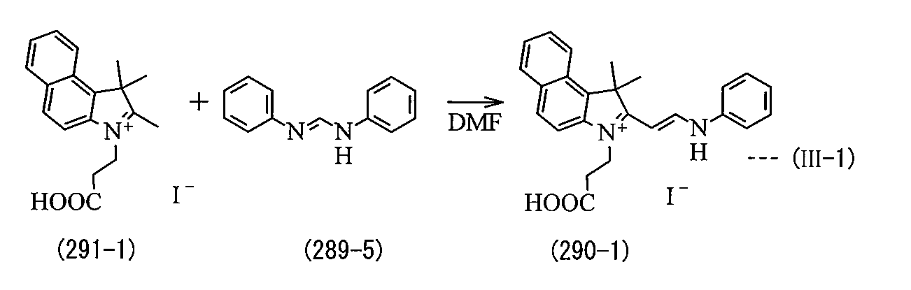
次に、式(IV-1)の化学反応式に示したように、式(290-1)で表されるシアニン中間体5mmolと、式(286-1)に示した4級アンモニウム塩5mmolと、無水酢酸((CH3CO)2O)20mmolと、塩基としてトリメチルアミン10mmolと、アセトニトリル(CH3 CN)10gとを混合し、その混合物を4時間加熱還流して反応させた。最後に、この反応物に対してクロロホルム10gと水10gとを加えたのち、析出した固体をろ別後、減圧乾燥することにより、5.1%の収率で最終生成物(式(8-1)で表される化合物を得た。
Next, as shown in the chemical reaction formula of the formula (IV-1), 5 mmol of the cyanine intermediate represented by the formula (290-1), 5 mmol of the quaternary ammonium salt shown in the formula (286-1), and , 20 mmol of acetic anhydride ((CH 3 CO) 2 O), 10 mmol of trimethylamine as a base, and 10 g of acetonitrile (CH 3 CN) were mixed, and the mixture was reacted by heating under reflux for 4 hours. Finally, 10 g of chloroform and 10 g of water were added to the reaction product, and the precipitated solid was filtered off and dried under reduced pressure to obtain the final product (formula (8- The compound represented by 1) was obtained.
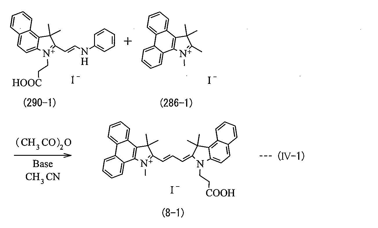
(実験例1-2)
式(9)に示した構造部およびヨウ化物イオンからなる化合物を合成した。この際、まず、実験例1-1の式(I-1)の化学反応式に示した手順と同様にして式(286-1)に示した4級アンモニウム塩を用意した。その一方で、式(I-3)の化学反応式に示したように、式(298-1)に示した化合物に代えて、式(298-2)で表される化合物を用いたことを除き、実験例1-1の式(I-2)の化学反応式に示した手順と同様にして式(291-2)で表される4級アンモニウム塩を得た。 (Experimental example 1-2)
A compound composed of the structure shown in formula (9) and iodide ions was synthesized. At this time, first, a quaternary ammonium salt represented by the formula (286-1) was prepared in the same manner as in the chemical reaction formula of the formula (I-1) in Experimental Example 1-1. On the other hand, as shown in the chemical reaction formula of the formula (I-3), the compound represented by the formula (298-2) was used instead of the compound represented by the formula (298-1). A quaternary ammonium salt represented by the formula (291-2) was obtained in the same manner as the procedure shown in the chemical reaction formula of the formula (I-2) in Experimental Example 1-1.

次に、式(III-2)の化学反応式に示したように、式(291-1)に示した4級アンモニウム塩に代えて式(291-2)で表される4級アンモニウム塩を用いると共に、式(289-5)に示したブリッジ剤に代えて式(289-6)で表されるブリッジ剤を用いたことを除き、実験例1-1の式(III-1)の化学反応式に示した手順と同様にして式(290-2)で表されるシアニン中間体を得た。
Next, as shown in the chemical reaction formula of the formula (III-2), a quaternary ammonium salt represented by the formula (291-2) is used instead of the quaternary ammonium salt shown in the formula (291-1). And the chemistry of formula (III-1) in Experimental Example 1-1, except that the bridging agent represented by formula (289-6) was used instead of the bridging agent represented by formula (289-5). A cyanine intermediate represented by the formula (290-2) was obtained in the same manner as the procedure shown in the reaction formula.
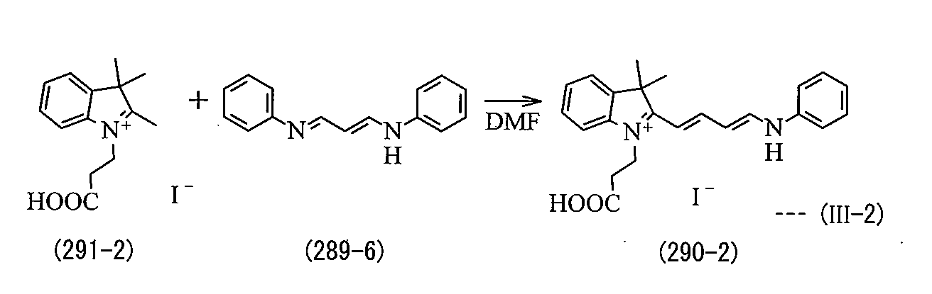
最後に、式(IV-2)の化学反応式に示したように、式(290-1)に示したシアニン中間体に代えて、式(290-2)に示したシアニン中間体を用いたことを除き、実験例1-1の式(IV-1)の化学反応式に示した手順と同様にして最終生成物(式(9-1)で表される化合物)を得た。この最終生成物の収率は8.6%であった。
Finally, as shown in the chemical reaction formula of the formula (IV-2), the cyanine intermediate shown in the formula (290-2) was used in place of the cyanine intermediate shown in the formula (290-1). The final product (compound represented by the formula (9-1)) was obtained in the same manner as the procedure shown in the chemical reaction formula of the formula (IV-1) in Experimental Example 1-1. The yield of this final product was 8.6%.

(実験例1-3)
式(11)に示した構造部およびヨウ化物イオンからなる化合物を合成した。この際、まず、式(IV-3)の化学反応式に示したように、式(286-2)で表される4級アンモニウム塩を用意すると共に、実験例1-2の式(I-3)および式(III-2)の化学反応式に示した手順と同様にして式(290-2)に示したシアニン中間体を用意した。続いて、式(286-1)に示した4級アンモニウム塩に代えて、式(286-2)で表される4級アンモニウム塩を用いたことを除き、実験例1-2の式(IV-2)の化学反応式に示した手順と同様にして、最終生成物(式(11-1)で表される化合物)を得た。この最終生成物の収率は16%であった。 (Experimental Example 1-3)
A compound composed of the structure shown in formula (11) and iodide ions was synthesized. At this time, first, as shown in the chemical reaction formula of the formula (IV-3), a quaternary ammonium salt represented by the formula (286-2) was prepared, and the formula (I- A cyanine intermediate represented by the formula (290-2) was prepared in the same manner as in the chemical reaction formulas of 3) and (III-2). Subsequently, the quaternary ammonium salt represented by the formula (286-2) was used in place of the quaternary ammonium salt represented by the formula (286-1), except that the formula (IV) of Experimental Example 1-2 was used. The final product (compound represented by formula (11-1)) was obtained in the same manner as the procedure shown in the chemical reaction formula of -2). The yield of this final product was 16%.

(実験例1-4)
式(13)に示した構造部およびヨウ化物イオンからなる化合物を合成した。この際、まず、式(IV-4)の化学反応式に示したように、式(286-3)で表される4級アンモニウム塩を用意すると共に、実験例1-2の式(I-3)および式(III-2)の化学反応式に示した手順と同様にして式(290-2)に示したシアニン中間体を用意した。続いて、式(286-1)に示した4級アンモニウム塩に代えて、式(286-3)に示した4級アンモニウム塩を用いたことを除き、実験例1-2の式(IV-2)の化学反応式に示した手順と同様にして、最終生成物(式(13-1)で表される化合物)を得た。この最終生成物の収率は4.5%であった。 (Experimental Example 1-4)
A compound composed of the structure shown in formula (13) and iodide ions was synthesized. At this time, first, as shown in the chemical reaction formula of the formula (IV-4), a quaternary ammonium salt represented by the formula (286-3) was prepared, and the formula (I- A cyanine intermediate represented by the formula (290-2) was prepared in the same manner as in the chemical reaction formulas of 3) and (III-2). Subsequently, the formula (IV- The final product (compound represented by formula (13-1)) was obtained in the same manner as the procedure shown in the chemical reaction formula of 2). The yield of this final product was 4.5%.

(実験例1-5)
上記した式(I)および式(V)の化学反応式に示した手順に従って、式(14)に示した構造部およびヨウ化物イオンからなる化合物を合成した。この際、まず、式(286-2)に示した4級アンモニウム塩を用意した。そののち、式(V-1)の化学反応式に示したように、式(286-2)に示した4級アンモニウム塩10mmolと、式(289-6)に示したブリッジ剤5mmolと、無水酢酸20mmolと、塩基としてトリメチルアミン10mmolと、アセトニトリル(CH3CN)10gとを混合し、その混合物を4時間加熱還流して反応させた。最後に、この反応物に対してクロロホルム10gと水10gとを加えたのち、析出した固体をろ別後、減圧乾燥することにより、4.2%の収率で最終生成物(式(14-1)で表される化合物)を得た。 (Experimental Example 1-5)
According to the procedure shown in the chemical reaction formulas of the above formulas (I) and (V), a compound composed of the structure part and the iodide ion shown in the formula (14) was synthesized. At this time, first, a quaternary ammonium salt represented by the formula (286-2) was prepared. After that, as shown in the chemical reaction formula of the formula (V-1), 10 mmol of the quaternary ammonium salt shown in the formula (286-2), 5 mmol of the bridging agent shown in the formula (289-6), and anhydrous 20 mmol of acetic acid, 10 mmol of trimethylamine as a base, and 10 g of acetonitrile (CH 3 CN) were mixed, and the mixture was reacted by heating under reflux for 4 hours. Finally, 10 g of chloroform and 10 g of water were added to the reaction product, and then the precipitated solid was filtered off and dried under reduced pressure, whereby the final product (formula (14- The compound represented by 1) was obtained.
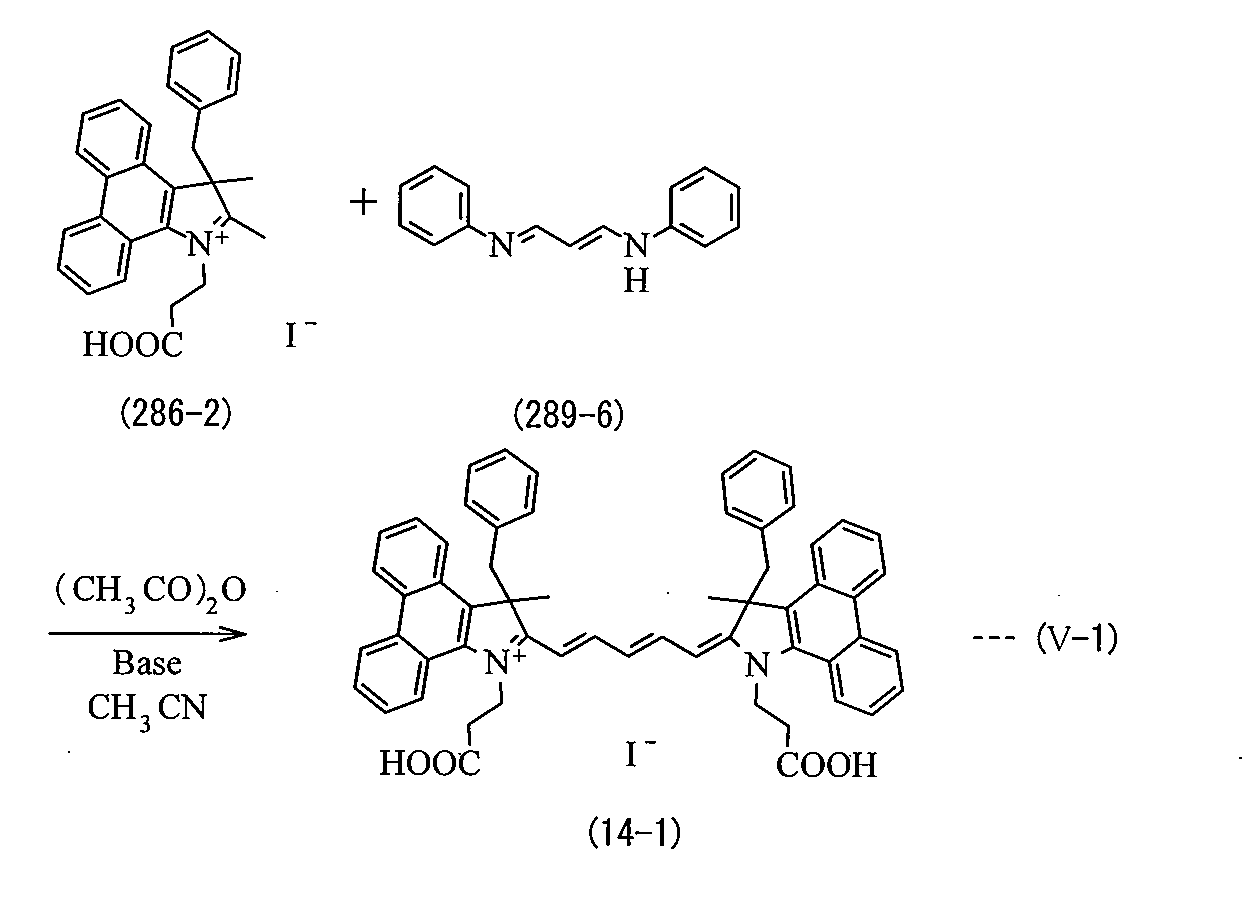
(実験例1-6)
式(15)に示した構造部およびヨウ化物イオンからなる化合物を合成した。この際、まず、式(III -3)の化学反応式に示したように、式(286-2)に示した4級アンモニウム塩を用意すると共に、実験例1-1の式(I-2)の化学反応式に示した手順と同様にして式(291-1)に示した4級アンモニウム塩を用意した。続いて、式(289-5)に示したブリッジ剤に代えて式(289-7)に示したブリッジ剤を用いたことを除き、実験例1-1の式(III-1)の化学反応式に示した手順と同様にして、式(290-3)で表されるシアニン中間体を得た。 (Experimental example 1-6)
A compound composed of the structure shown in formula (15) and iodide ions was synthesized. At this time, first, as shown in the chemical reaction formula of the formula (III-3), the quaternary ammonium salt shown in the formula (286-2) was prepared, and the formula (I-2) of the experimental example 1-1 was prepared. The quaternary ammonium salt represented by the formula (291-1) was prepared in the same manner as in the chemical reaction formula of Subsequently, the chemical reaction of Formula (III-1) in Experimental Example 1-1 was used except that the bridge agent shown in Formula (289-7) was used instead of the bridge agent shown in Formula (289-5). The cyanine intermediate represented by the formula (290-3) was obtained in the same manner as the procedure shown in the formula.

最後に、式(IV-5)の化学反応式に示したように、式(290-2)に示したシアニン中間体に代えて、式(290-3)に示したシアニン中間体を用いたことを除き、実験例1-3の式(IV-3)の化学反応式に示した手順と同様にして、最終生成物(式(15-1)で表される化合物)を得た。この最終生成物の収率は7.4%であった。
Finally, as shown in the chemical reaction formula of the formula (IV-5), the cyanine intermediate shown in the formula (290-3) was used in place of the cyanine intermediate shown in the formula (290-2). The final product (compound represented by formula (15-1)) was obtained in the same manner as the procedure shown in the chemical reaction formula of formula (IV-3) in Experimental Example 1-3. The yield of this final product was 7.4%.

これらの実験例1-1~1-6の最終生成物について、核磁気共鳴法(nuclear magnetic resonance;NMR)により構造を同定すると共に、最大吸収波長(λmax)を調べたところ、表1に示した結果を得た。
The final products of these experimental examples 1-1 to 1-6 were identified by the nuclear magnetic resonance method (NMR) and the maximum absorption wavelength (λmax) was examined. Obtained results.
NMR測定する際には、測定機器としてJEOL社製のLambda-400を用いた。この場合、実験例1-1~1-4および実験例1-6では、重溶媒である重水素化されたジメチルスルホキシド(DMSO-d6)1cm3に対して最終生成物3~10mgを溶解させた溶液を測定試料とし、室温にて1H-NMRスペクトルを測定した。また、実験例1-5では、重溶媒としてDMSO-d6に代えて、重水素化されたクロロホルム(CDCl3)を用いたことを除き、実験例1-1等と同様にして測定した。
For NMR measurement, Lambda-400 manufactured by JEOL was used as a measuring instrument. In this case, in Experimental Examples 1-1 to 1-4 and Experimental Example 1-6, 3 to 10 mg of the final product was dissolved in 1 cm 3 of deuterated dimethyl sulfoxide (DMSO-d6) as a deuterated solvent. The solution was used as a measurement sample, and a 1 H-NMR spectrum was measured at room temperature. In Experimental Example 1-5, measurement was performed in the same manner as in Experimental Example 1-1, except that deuterated chloroform (CDCl 3 ) was used instead of DMSO-d6 as the deuterated solvent.
最大吸収波長(λmax)を調べる際には、日立製作所製のUVスペクトルメータ(U-3010)を用いた。この場合には、最終生成物をメタノール(CH3OH;溶媒)に対して、吸光度が0.5~1.0の範囲内になるように調製して測定に用いた。
When examining the maximum absorption wavelength (λmax), a UV spectrum meter (U-3010) manufactured by Hitachi, Ltd. was used. In this case, the final product was prepared for methanol (CH 3 OH; solvent) so that the absorbance was in the range of 0.5 to 1.0 and used for measurement.

表1に示したように、実験例1-1~1-6では、それぞれ式(8-1)、式(9-1)、式(11-1)、式(13-1)~式(15-1)に示した化合物が合成されたことが確認された。
As shown in Table 1, in Experimental Examples 1-1 to 1-6, the equations (8-1), (9-1), (11-1), (13-1) to (13) It was confirmed that the compound shown in 15-1) was synthesized.
(実験例2-1)
実験例1-1で合成した式(8-1)に示した化合物を用いて、上記実施の形態で説明した光電変換素子の具体例として色素増感型太陽電池を以下の手順により作製した。 (Experimental example 2-1)
Using the compound represented by Formula (8-1) synthesized in Experimental Example 1-1, a dye-sensitized solar cell was produced according to the following procedure as a specific example of the photoelectric conversion element described in the above embodiment.
まず、作用電極10を作製した。最初に、縦2.0cm×横1.5cm×厚さ1.1mmの導電性ガラス基板(F-SnO2 )よりなる導電性基板11を用意した。続いて、導電性基板11に、縦0.5cm×横0.5cmの四角形を囲むように厚さ70μmのマスキングテープを貼り、この部分に金属酸化物スラリー3cm3を一様の厚さとなるように塗布して乾燥させた。この場合、金属酸化物スラリーとしては、10重量%となるように酸化亜鉛粉末(表面積60m2/g、平均一次粒径50nm以下;堺化学工業社製FINEX-30)を、非イオン性界面活性剤としてTritonX-100(Tritonは登録商標)を1滴添加した水に懸濁して調製したものを用いた。続いて、導電性基板11上のマスキングテープを剥がし取り、この基板を電気炉により450℃で焼成し、厚さ約5μmの金属酸化物半導体層12を形成した。続いて、式(1)に示したシアニン化合物である式(8-1)に示した化合物とデオキシコール酸とをそれぞれ3×10-4mol/dm3および1×10-2mol/dm3の濃度になるように無水エタノールに溶解させて、色素溶液を調製した。続いて、金属酸化物半導体層12が形成された導電性基板11を上記の色素溶液に浸漬し、色素13を担持させた。
First, the working electrode 10 was produced. First, a conductive substrate 11 made of a conductive glass substrate (F-SnO 2 ) having a length of 2.0 cm, a width of 1.5 cm, and a thickness of 1.1 mm was prepared. Subsequently, a masking tape having a thickness of 70 μm is attached to the conductive substrate 11 so as to surround a square of 0.5 cm in length and 0.5 cm in width, and 3 cm 3 of metal oxide slurry is formed to have a uniform thickness on this portion. And dried. In this case, a zinc oxide powder (surface area 60 m 2 / g, average primary particle size 50 nm or less; FINEX-30 manufactured by Sakai Chemical Industry Co., Ltd.) is used as the metal oxide slurry so as to be 10% by weight. An agent prepared by suspending in water to which 1 drop of Triton X-100 (Triton is a registered trademark) was added was used. Subsequently, the masking tape on the conductive substrate 11 was peeled off, and this substrate was baked at 450 ° C. in an electric furnace to form a metal oxide semiconductor layer 12 having a thickness of about 5 μm. Subsequently, the compound represented by the formula (8-1), which is the cyanine compound represented by the formula (1), and deoxycholic acid were respectively 3 × 10 −4 mol / dm 3 and 1 × 10 −2 mol / dm 3. A dye solution was prepared by dissolving in absolute ethanol so that the concentration of Subsequently, the conductive substrate 11 on which the metal oxide semiconductor layer 12 was formed was immersed in the above dye solution, and the dye 13 was supported.
次に、縦2.0cm×横1.5cm×厚さ1.1mmの導電性ガラス基板(F-SnO2 )よりなる導電性基板21の片面に、スパッタリングにより白金よりなる100nmの厚さの導電層22を形成することにより、対向電極20を作製した。この場合、予め、導電性基板21には、電解液注入用の穴(φ1mm)を2つ開けておいた。
Next, a conductive substrate having a thickness of 100 nm made of platinum is formed on one surface of a conductive substrate 21 made of a conductive glass substrate (F-SnO 2 ) having a length of 2.0 cm, a width of 1.5 cm, and a thickness of 1.1 mm. The counter electrode 20 was produced by forming the layer 22. In this case, two holes (φ1 mm) for injecting an electrolytic solution were formed in the conductive substrate 21 in advance.
次に、電解液を調製した。アセトニトリルに対して、ジメチルヘキシルイミダゾリウムヨージド(0.6mol/dm3 )、ヨウ化リチウム(0.1mol/dm3)、ヨウ素(0.05mol/dm3)の濃度になるように調製した。
Next, an electrolytic solution was prepared. It adjusted so that it might become a density | concentration of dimethylhexyl imidazolium iodide (0.6 mol / dm < 3 >), lithium iodide (0.1 mol / dm < 3 >), and iodine (0.05 mol / dm < 3 >) with respect to acetonitrile.
次に、厚さ50μmのスペーサを金属酸化物半導体層12の周りを囲むように配置したのち、作用電極10の色素13を担持した面と、対向電極20の導電層22を形成した面とを対向させると共に、スペーサを介して貼り合わせた。こののち、対向電極20に開けておいた注入口から調製した電解液を注入し、電解質含有層30を形成した。最後に全体を封止することにより、色素増感型太陽電池を得た。
Next, after arranging a spacer having a thickness of 50 μm so as to surround the metal oxide semiconductor layer 12, the surface of the working electrode 10 carrying the dye 13 and the surface of the counter electrode 20 on which the conductive layer 22 is formed are formed. It was made to oppose and it bonded together through the spacer. After that, an electrolyte prepared from an injection port opened in the counter electrode 20 was injected to form the electrolyte containing layer 30. Finally, the whole was sealed to obtain a dye-sensitized solar cell.
(実験例2-2~2-8)
色素として、式(8-1)に示した化合物に代えて、実験例1-2で合成した式(9-1)に示した化合物(実験例2-2)、式(10-1)で表される化合物(実験例2-3)、実験例1-3で合成した式(11-1)に示した化合物(実験例2-4)、式(12-1)で表される化合物(実験例2-5)、実験例1-4で合成した式(13-1)に示した化合物(実験例2-6)、実験例1-5で合成した式(14-1)に示した化合物(実験例2-7)あるいは実験例1-6で合成した式(15-1)に示した化合物(実験例2-8)を用いたことを除き、実験例2-1と同様の手順を経た。なお、実験例として具体的な合成手順および最終合成物の物性データ等を示していないが、式(10-1)に示した化合物および式(12-1)に示した化合物についても上記した実験例1-1等と同様にして合成することができる。 (Experimental Examples 2-2 to 2-8)
Instead of the compound represented by formula (8-1) as the dye, the compound represented by formula (9-1) synthesized in Experimental Example 1-2 (Experimental Example 2-2) and Formula (10-1) The compound represented by the formula (Experimental Example 2-3), the compound represented by the formula (11-1) synthesized in the Experimental Example 1-3 (Experimental Example 2-4), the compound represented by the formula (12-1) ( Experimental Example 2-5), a compound shown in Formula (13-1) synthesized in Experimental Example 1-4 (Experimental Example 2-6), and a compound shown in Formula (14-1) synthesized in Experimental Example 1-5 The same procedure as in Experimental Example 2-1 except that the compound (Experimental Example 2-7) or the compound shown in Formula (15-1) (Experimental Example 2-8) synthesized in Experimental Example 1-6 was used. It went through. In addition, although specific synthesis procedures and physical property data of the final synthesized product are not shown as experimental examples, the above-described experiment was also performed on the compound represented by formula (10-1) and the compound represented by formula (12-1). It can be synthesized in the same manner as in Example 1-1.

(実験例2-9~2-15)
実験例2-1~2-8に対する比較例として、色素である式(8-1)に示した化合物に代えて、以下の式(299)~式(305)に示した化合物(色素)を用いたことを除き、実験例2-1と同様の手順を経た。 (Experimental Examples 2-9 to 2-15)
As a comparative example for Experimental Examples 2-1 to 2-8, the following compounds (dyes) represented by the following formulas (299) to (305) were used instead of the compounds represented by the formula (8-1) as the dyes. A procedure similar to that of Experimental example 2-1 was performed except that it was used.

これらの実験例2-1~2-15の色素増感型太陽電池について変換効率を調べたところ、表2に示した結果が得られた。また、これらの実験例を代表して実験例2-7および実験例2-13の色素増感型太陽電池についてIPCEを調べたところ、図3に示した結果が得られた。
When the conversion efficiency of the dye-sensitized solar cells of Experimental Examples 2-1 to 2-15 was examined, the results shown in Table 2 were obtained. Further, when IPCE was examined for the dye-sensitized solar cells of Experimental Examples 2-7 and 2-13 on behalf of these experimental examples, the results shown in FIG. 3 were obtained.
変換効率は、光源AM1.5(1000W/m2 )のソーラーシュミレータを用いて、以下の算出方法により求めた。まず、色素増感型太陽電池の電圧をソースメータにて掃引し、応答電流を測定した。これにより、電圧と電流との積である最大出力を1cm2あたりの光強度で除した値に100を乗じてパーセント表示した値を変換効率(η:%)とした。すなわち、変換効率は、(最大出力/1cm2あたりの光強度)×100で表される。また、IPCEを測定する際には、測定装置としてペクセルテクノロジー社製のSM-10ACを用いた。なお、図3では、実験例2-7の測定結果および実験例2-13の測定結果をそれぞれ曲線C11および曲線C21として示した。
The conversion efficiency was calculated | required with the following calculation methods using the solar simulator of light source AM1.5 (1000 W / m < 2 >). First, the voltage of the dye-sensitized solar cell was swept with a source meter, and the response current was measured. As a result, a value obtained by multiplying the value obtained by dividing the maximum output, which is the product of voltage and current, by the light intensity per 1 cm 2 and multiplying by 100 was defined as conversion efficiency (η:%). That is, the conversion efficiency is expressed by (maximum output / 1 light intensity per 1 cm 2 ) × 100. Further, when measuring IPCE, SM-10AC manufactured by Pexel Technology was used as a measuring device. In FIG. 3, the measurement result of Experimental Example 2-7 and the measurement result of Experimental Example 2-13 are shown as curve C11 and curve C21, respectively.

表2に示したように、金属酸化物半導体層12が焼成法により形成されると共に酸化亜鉛を含む場合において、色素13がフェナンスレン骨格を有する式(8-1)に示した化合物等を含む実験例2-1~2-8では、フェナンスレン骨格を含まない式(299)に示した化合物等を用いた実験例2-9~2-15よりも変換効率が高くなった。詳細には、炭素原子数3のメチン鎖骨格を有するシアニン化合物を用いた実験例2-1おいて、同じメチン鎖骨格を有するがフェナンスレン骨格をもたない実験例2-9,2-10よりも変換効率が著しく高くなり、4倍程となった。この傾向は、実験例2-2~2-8と実験例2-11~2-15との比較からも明らかなように、炭素原子数5のメチン鎖骨格を有するシアニン化合物を用いた場合においても同様であった。
As shown in Table 2, in the case where the metal oxide semiconductor layer 12 is formed by a firing method and contains zinc oxide, the experiment in which the dye 13 includes the compound represented by the formula (8-1) having a phenanthrene skeleton In Examples 2-1 to 2-8, the conversion efficiency was higher than Experimental Examples 2-9 to 2-15 using the compound represented by the formula (299) that does not contain a phenanthrene skeleton. Specifically, in Experimental Example 2-1 using a cyanine compound having a methine chain skeleton having 3 carbon atoms, from Experimental Examples 2-9 and 2-10 having the same methine chain skeleton but no phenanthrene skeleton However, the conversion efficiency was remarkably increased, and was about 4 times. This tendency is apparent in the case of using a cyanine compound having a methine chain skeleton having 5 carbon atoms, as is clear from comparison between Experimental Examples 2-2 to 2-8 and Experimental Examples 2-11 to 2-15. Was the same.
また、図3に示したように、フェナンスレン骨格を含むシアニン化合物を用いた実験例2-7(曲線C11)では、フェナンスレン骨格の代わりにベンゼン骨格を有するシアニン化合物を用いた実験例2-13(曲線C21)よりも広い波長域の光を吸収して電流に変換していた。詳細には、実験例2-7では、750nm程度の波長においてIPCEの割合が最も高く40%程度となるピークがあり、そのピークの半値幅は200nm程度であった。これに対して実験例2-13では、680nm程度の波長においてIPCEの割合が最も高く40%程度となるピークがあるが、そのピークの半値幅は120nm程度であった。
Further, as shown in FIG. 3, in Experimental Example 2-7 (curve C11) using a cyanine compound containing a phenanthrene skeleton, Experimental Example 2-13 using a cyanine compound having a benzene skeleton instead of the phenanthrene skeleton (curve C11) Light in a wider wavelength range than the curve C21) was absorbed and converted to an electric current. Specifically, in Experimental Example 2-7, there was a peak where the IPCE ratio was the highest at a wavelength of about 750 nm and was about 40%, and the half width of the peak was about 200 nm. On the other hand, in Experimental Example 2-13, there is a peak at which the IPCE ratio is the highest at a wavelength of about 680 nm and is about 40%.
これらの結果は、以下のことを表している。すなわち、式(8-1)に示した化合物等の光吸収ピーク波長は、フェナンスレン骨格を含むことによる分子全体としてのπ共役の広がりによって、フェナンスレン骨格の代わりにベンゼン骨格あるいはナフタレン骨格を含むシアニン化合物(式(299)~式(305)に示した化合物)の光吸収ピーク波長と比較して、長波長側にシフトしているが、光吸収ピーク強度は同程度となると共に、光吸収ピークはブロード化し、そのピーク幅が広くなる。このため、色素13が式(8-1)に示した化合物等が含むことにより、色素13が広い波長域の光を吸収して励起され、金属酸化物半導体層12に対して効率よく電子を注入する。よって、照射された光量(色素13に入射した光量)に対して光電変換されて生成される電流量が高くなる。
These results represent the following. That is, the light absorption peak wavelength of the compound or the like represented by the formula (8-1) is a cyanine compound containing a benzene skeleton or a naphthalene skeleton instead of the phenanthrene skeleton due to the spread of π conjugation as a whole molecule due to the inclusion of the phenanthrene skeleton. Compared to the light absorption peak wavelength of (the compounds represented by the formulas (299) to (305)), the light absorption peak intensity is about the same, and the light absorption peak is It becomes broader and its peak width becomes wider. Therefore, when the dye 13 includes the compound represented by the formula (8-1), the dye 13 is excited by absorbing light in a wide wavelength range, and efficiently emits electrons to the metal oxide semiconductor layer 12. inject. Therefore, the amount of current generated by photoelectric conversion with respect to the irradiated light amount (the light amount incident on the dye 13) increases.
また、実験例2-3と実験例2-4との比較から、式(1)においてアンカー基(-CH2 -CH2 -COOH)がY1およびY2のうちのいずれか一方として導入されたシアニン化合物を用いた場合よりも、それらの双方に導入されたシアニン化合物を用いる場合において、変換効率が高くなる傾向が見られた。この結果から、式(1)に示したシアニン化合物では、Y1およびY2の双方としてアンカー基が導入されることにより、金属酸化物半導体層12に対する吸着性および電子注入効率が高くなるものと考えられる。
Further, from the comparison between Experimental Example 2-3 and Experimental Example 2-4, cyanine in which an anchor group (—CH 2 —CH 2 —COOH) was introduced as one of Y1 and Y2 in Formula (1) There was a tendency for conversion efficiency to be higher in the case of using the cyanine compound introduced in both of them than in the case of using the compound. From this result, in the cyanine compound represented by the formula (1), it is considered that the adsorbability and the electron injection efficiency with respect to the metal oxide semiconductor layer 12 are increased by introducing an anchor group as both Y1 and Y2. .
また、実験例2-2と実験例2-3との比較から、式(1)においてR7,R8,R10およびR11のうちの1つとしてベンジル基などの式(2)に示した基のような立体的に嵩高い基が導入されたシアニン化合物を用いることにより、変換効率がより高くなる傾向が見られた。また、実験例2-4と実験例2-6との比較から、ベンジル基が2つ導入されたシアニン化合物を用いることにより、変換効率がより高くなる傾向が見られた。これらの結果から、式(1)に示した化合物では、R7,R8,R10およびR11のうちの少なくとも1つとして式(2)に示した基が導入されることにより、変換効率の向上に寄与しづらい会合体の形成が抑制されるものと考えられる。
Further, from comparison between Experimental Example 2-2 and Experimental Example 2-3, in Formula (1), as one of R7, R8, R10 and R11, a group such as benzyl group shown in Formula (2) By using a cyanine compound into which a sterically bulky group was introduced, the conversion efficiency tended to be higher. Further, from comparison between Experimental Example 2-4 and Experimental Example 2-6, it was found that the conversion efficiency tends to be higher by using a cyanine compound into which two benzyl groups are introduced. From these results, in the compound represented by the formula (1), the group represented by the formula (2) is introduced as at least one of R7, R8, R10 and R11, thereby contributing to the improvement of the conversion efficiency. It is thought that formation of difficult aggregates is suppressed.
さらに、実験例2-5と実験例2-8との比較から、メチン鎖骨格にシアノ基が導入されたシアニン化合物を用いた場合において、変換効率がより高くなる傾向が見られた。この結果から、式(1)に示したシアニン化合物では、メチン鎖骨格にシアノ基が導入されることにより、金属酸化物半導体層12に対する吸着性および電子注入効率のうちの少なくとも一方が高くなるものと考えられる。
Further, from comparison between Experimental Example 2-5 and Experimental Example 2-8, it was found that the conversion efficiency tended to be higher when a cyanine compound having a cyano group introduced into the methine chain skeleton was used. From this result, in the cyanine compound represented by the formula (1), at least one of the adsorptivity to the metal oxide semiconductor layer 12 and the electron injection efficiency is increased by introducing a cyano group into the methine chain skeleton. it is conceivable that.
これらのことから、金属酸化物半導体層12が焼成法により形成されると共に酸化亜鉛を含む光電変換素子では、以下のことが確認された。すなわち、色素13が式(1)に示したシアニン化合物(具体的には式(4)あるいは式(5)に示した化合物)を含むことにより、そのシアニン化合物の種類に依存することなく、変換効率を向上させることができる。この場合、式(1)に示したシアニン化合物において、Y1およびY2の双方がアンカー基であれば、変換効率をより向上させることができる。また、R7,R8,R10およびR11のうちの少なくとも1つが式(2)に示した基であれば、より高い変換効率が得られ、さらにまた、メチン鎖骨格にシアノ基が導入されていれば、さらに高い変換効率を得ることができる。
From these facts, the following was confirmed in the photoelectric conversion element in which the metal oxide semiconductor layer 12 is formed by the firing method and contains zinc oxide. That is, by including the cyanine compound represented by the formula (1) (specifically, the compound represented by the formula (4) or the formula (5)), the dye 13 can be converted without depending on the type of the cyanine compound. Efficiency can be improved. In this case, in the cyanine compound represented by the formula (1), if both Y1 and Y2 are anchor groups, the conversion efficiency can be further improved. Further, if at least one of R7, R8, R10 and R11 is a group represented by the formula (2), higher conversion efficiency can be obtained, and furthermore, if a cyano group is introduced into the methine chain skeleton. Higher conversion efficiency can be obtained.
(実験例3-1~3-15)
電解析出法により金属酸化物半導体層12を形成したことを除き、実験例2-1~2-15と同様の手順を経た。電解析出法により金属酸化物半導体層12を形成する場合には、以下の手順により行った。まず、水に対してエオシンY(30μmol/dm3)、塩化亜鉛(5mmol/dm3)、塩化カリウム(0.09mol/dm3)の濃度になるように調製した電解浴液40mlと、亜鉛板よりなる対極と、銀/塩化銀電極よりなる参照電極とを用意した。続いて、電解浴を酸素により15分間バブリングしたのち、電解浴中の溶液の温度を70℃とし、60分、電位-1.0Vの定電位電解をバブリングしながら導電性基板11の表面に製膜した。最後に、この基板を、乾燥させることなく水酸化カリウム水溶液(pH11)に浸漬し、そののち水洗することによりエオシンYを脱着した。続いて、150℃、30分間乾燥させた。 (Experimental examples 3-1 to 3-15)
The same procedure as in Experimental Examples 2-1 to 2-15 was performed except that the metaloxide semiconductor layer 12 was formed by electrolytic deposition. When forming the metal oxide semiconductor layer 12 by the electrolytic deposition method, the following procedure was used. First, 40 ml of an electrolytic bath solution prepared to have a concentration of eosin Y (30 μmol / dm 3 ), zinc chloride (5 mmol / dm 3 ), potassium chloride (0.09 mol / dm 3 ) with respect to water, and a zinc plate And a reference electrode made of a silver / silver chloride electrode. Subsequently, after bubbling the electrolytic bath with oxygen for 15 minutes, the temperature of the solution in the electrolytic bath was set to 70 ° C., and 60 minutes was produced on the surface of the conductive substrate 11 while bubbling constant potential electrolysis at a potential of −1.0 V. Filmed. Finally, this substrate was immersed in an aqueous potassium hydroxide solution (pH 11) without drying, and then washed with water to desorb eosin Y. Subsequently, it was dried at 150 ° C. for 30 minutes.
電解析出法により金属酸化物半導体層12を形成したことを除き、実験例2-1~2-15と同様の手順を経た。電解析出法により金属酸化物半導体層12を形成する場合には、以下の手順により行った。まず、水に対してエオシンY(30μmol/dm3)、塩化亜鉛(5mmol/dm3)、塩化カリウム(0.09mol/dm3)の濃度になるように調製した電解浴液40mlと、亜鉛板よりなる対極と、銀/塩化銀電極よりなる参照電極とを用意した。続いて、電解浴を酸素により15分間バブリングしたのち、電解浴中の溶液の温度を70℃とし、60分、電位-1.0Vの定電位電解をバブリングしながら導電性基板11の表面に製膜した。最後に、この基板を、乾燥させることなく水酸化カリウム水溶液(pH11)に浸漬し、そののち水洗することによりエオシンYを脱着した。続いて、150℃、30分間乾燥させた。 (Experimental examples 3-1 to 3-15)
The same procedure as in Experimental Examples 2-1 to 2-15 was performed except that the metal
これらの実験例3-1~3-15の色素増感型太陽電池について変換効率を求めたところ、表3に示した結果が得られた。
When conversion efficiency was determined for the dye-sensitized solar cells of Experimental Examples 3-1 to 3-15, the results shown in Table 3 were obtained.

表3に示したように、金属酸化物半導体層12が電解析出法により形成された場合においても、表2に示した結果と同様の結果が得られた。すなわち、色素13がフェナンスレン骨格を有する式(8-1)に示した化合物等を含む実験例3-1~3-8では、フェナンスレン骨格を含まない式(299)に示した化合物等を用いた実験例3-9~3-15よりも変換効率が高くなった。
As shown in Table 3, when the metal oxide semiconductor layer 12 was formed by the electrolytic deposition method, the same results as those shown in Table 2 were obtained. That is, in Experimental Examples 3-1 to 3-8 in which the dye 13 includes the compound represented by the formula (8-1) having a phenanthrene skeleton, the compound represented by the formula (299) not including the phenanthrene skeleton was used. The conversion efficiency was higher than in Experimental Examples 3-9 to 3-15.
この場合においても、実験例3-3と実験例3-4とを比較すると、式(1)においてアンカー基(-CH2 -CH2 -COOH)がY1およびY2の双方に導入されているシアニン化合物を用いた場合において、変換効率が高くなった。また、実験例3-2と実験例3-3、および実験例3-4と実験例3-6とを比較すると、式(1)においてR7,R8,R10およびR11のうちの少なくとも1つとして、ベンジル基などの式(2)に示した基が導入されているシアニン化合物を用いた場合において、変換効率がより高くなった。さらに、実験例3-5と実験例3-8との比較から、メチン鎖骨格にシアノ基が導入されたシアニン化合物を用いた場合において、変換効率がより高くなった。
Even in this case, when Experimental Example 3-3 and Experimental Example 3-4 are compared, cyanine in which an anchor group (—CH 2 —CH 2 —COOH) is introduced into both Y1 and Y2 in Formula (1) When the compound was used, the conversion efficiency increased. In addition, when Experimental Example 3-2 and Experimental Example 3-3, and Experimental Example 3-4 and Experimental Example 3-6 are compared, at least one of R7, R8, R10, and R11 in Formula (1) is obtained. In the case of using a cyanine compound into which a group represented by the formula (2) such as benzyl group was introduced, the conversion efficiency was higher. Further, from comparison between Experimental Example 3-5 and Experimental Example 3-8, the conversion efficiency was higher when a cyanine compound having a cyano group introduced into the methine chain skeleton was used.
これらのことから、金属酸化物半導体層12が電解析出法により形成されると共に酸化亜鉛を含む光電変換素子においても、以下のことが確認された。すなわち、色素13が式(1)に示したシアニン化合物を含むことにより、そのシアニン化合物の種類に依存することなく、変換効率を向上させることができる。この場合においても、式(1)に示したシアニン化合物において、Y1およびY2の双方がアンカー基であったり、R7,R8,R10およびR11のうちの少なくとも1つが式(2)に示した基であったり、または、メチン鎖骨格にシアノ基が導入されていれば、さらに高い変換効率を得ることができる。
From these, the following was also confirmed in the photoelectric conversion element in which the metal oxide semiconductor layer 12 was formed by electrolytic deposition and contained zinc oxide. That is, the conversion efficiency can be improved without depending on the kind of the cyanine compound, when the pigment | dye 13 contains the cyanine compound shown in Formula (1). Even in this case, in the cyanine compound represented by the formula (1), both Y1 and Y2 are anchor groups, or at least one of R7, R8, R10 and R11 is a group represented by the formula (2). If the cyano group is introduced into the methine chain skeleton, higher conversion efficiency can be obtained.
(実験例4-1~4-15)
焼成法により金属酸化物半導体層12を形成する際に、酸化亜鉛粉末に代えて、酸化チタン(TiO2 )粉末を含む金属酸化物スラリーを用いたことを除き、実験例2-1~2-15と同様の手順を経た。この場合、酸化チタン粉末を含む金属酸化物スラリーは、以下のように調製した。まず、チタンイソプロポキシド125cm3を、0.1mol/dm3硝酸水溶液750cm3 に攪拌しながら添加し、80℃で8時間激しく攪拌した。得られた液体をテフロン(登録商標)製の圧力容器に注ぎ入れ、その圧力容器を230℃、16時間オートクレーブにて処理した。そののちオートクレーブ処理した沈殿物を含む液体(ゾル液)を攪拌することにより再懸濁させた。続いて、この懸濁液を吸引濾過して再懸濁しなかった沈殿物を除き、ゾル状の濾液をエバポレータで酸化チタン濃度が11質量%になるまで濃縮した。こののち、濃縮液に基板への塗れ性を高めるためにTritonX-100を1滴添加した。続いて、平均粒径30nmの酸化チタン粉末(日本アエロジル社製P-25)をこのゾル状の濃縮液に、酸化チタンの含有率が全体として33質量%となるように加え、自転公転を利用した遠心撹拌を1時間行い、分散させた。 (Experimental examples 4-1 to 4-15)
When forming the metaloxide semiconductor layer 12 by the firing method, except for using a metal oxide slurry containing titanium oxide (TiO 2 ) powder instead of zinc oxide powder, Experimental Examples 2-1 to 2- The same procedure as 15 was performed. In this case, a metal oxide slurry containing titanium oxide powder was prepared as follows. First, titanium isopropoxide 125 cm 3, was added with stirring to 0.1 mol / dm 3 aqueous solution of nitric acid 750 cm 3, and 8 hours vigorously stirred at 80 ° C.. The obtained liquid was poured into a pressure vessel made of Teflon (registered trademark), and the pressure vessel was treated in an autoclave at 230 ° C. for 16 hours. After that, the liquid (sol solution) containing the autoclaved precipitate was resuspended by stirring. Subsequently, the suspension was subjected to suction filtration to remove precipitates that were not resuspended, and the sol-like filtrate was concentrated with an evaporator until the titanium oxide concentration became 11% by mass. After that, 1 drop of TritonX-100 was added to the concentrate to enhance the paintability to the substrate. Subsequently, titanium oxide powder having an average particle size of 30 nm (P-25 manufactured by Nippon Aerosil Co., Ltd.) was added to the sol-like concentrated solution so that the total content of titanium oxide was 33% by mass, and rotation revolution was used. Centrifugal stirring was performed for 1 hour to disperse.
焼成法により金属酸化物半導体層12を形成する際に、酸化亜鉛粉末に代えて、酸化チタン(TiO2 )粉末を含む金属酸化物スラリーを用いたことを除き、実験例2-1~2-15と同様の手順を経た。この場合、酸化チタン粉末を含む金属酸化物スラリーは、以下のように調製した。まず、チタンイソプロポキシド125cm3を、0.1mol/dm3硝酸水溶液750cm3 に攪拌しながら添加し、80℃で8時間激しく攪拌した。得られた液体をテフロン(登録商標)製の圧力容器に注ぎ入れ、その圧力容器を230℃、16時間オートクレーブにて処理した。そののちオートクレーブ処理した沈殿物を含む液体(ゾル液)を攪拌することにより再懸濁させた。続いて、この懸濁液を吸引濾過して再懸濁しなかった沈殿物を除き、ゾル状の濾液をエバポレータで酸化チタン濃度が11質量%になるまで濃縮した。こののち、濃縮液に基板への塗れ性を高めるためにTritonX-100を1滴添加した。続いて、平均粒径30nmの酸化チタン粉末(日本アエロジル社製P-25)をこのゾル状の濃縮液に、酸化チタンの含有率が全体として33質量%となるように加え、自転公転を利用した遠心撹拌を1時間行い、分散させた。 (Experimental examples 4-1 to 4-15)
When forming the metal
これらの実験例4-1~4-15の色素増感型太陽電池について、変換効率を調べたところ、表4に示した結果が得られた。
When the conversion efficiencies of the dye-sensitized solar cells of Experimental Examples 4-1 to 4-15 were examined, the results shown in Table 4 were obtained.

表4に示したように、金属酸化物半導体層12が焼成法により形成されると共に酸化チタンを含む場合においても、表2に示した結果と同様の結果が得られた。すなわち、色素13がフェナンスレン骨格を有する式(8-1)に示した化合物等を含む実験例4-1~4-8では、フェナンスレン骨格を含まない式(299)に示した化合物等を用いた実験例4-9~4-15よりも変換効率が高くなった。
As shown in Table 4, when the metal oxide semiconductor layer 12 was formed by the firing method and contained titanium oxide, the same results as those shown in Table 2 were obtained. That is, in Experimental Examples 4-1 to 4-8 in which the dye 13 includes the compound represented by the formula (8-1) having a phenanthrene skeleton, the compound represented by the formula (299) not including the phenanthrene skeleton was used. The conversion efficiency was higher than in Experimental Examples 4-9 to 4-15.
この場合においても、実験例4-3と実験例4-4とを比較すると、式(1)においてアンカー基(-CH2 -CH2 -COOH)がY1およびY2の双方に導入されているシアニン化合物を用いた場合において、変換効率が高くなった。また、実験例4-2と実験例4-3、および実験例4-4と実験例4-6とを比較すると、式(1)においてR7,R8,R10およびR11のうちの少なくとも1つとして、ベンジル基が導入されているシアニン化合物を用いた場合において、変換効率がより高くなった。さらに、実験例4-5と実験例4-8とを比較すると、メチン鎖骨格にシアノ基が導入されたシアニン化合物を用いた場合において、変換効率がより高くなった。
Even in this case, when Experimental Example 4-3 and Experimental Example 4-4 are compared, cyanine in which an anchor group (—CH 2 —CH 2 —COOH) is introduced into both Y1 and Y2 in Formula (1) When the compound was used, the conversion efficiency increased. Further, when Experimental Example 4-2 and Experimental Example 4-3, and Experimental Example 4-4 and Experimental Example 4-6 are compared, at least one of R7, R8, R10, and R11 in Formula (1) is obtained. In the case of using a cyanine compound into which a benzyl group was introduced, the conversion efficiency was higher. Further, comparing Experimental Example 4-5 and Experimental Example 4-8, the conversion efficiency was higher when a cyanine compound having a cyano group introduced into the methine chain skeleton was used.
これらのことから、金属酸化物半導体層12が焼成法により形成されると共に酸化チタンを含む光電変換素子においても、以下のことが確認された。すなわち、色素13が式(1)に示したシアニン化合物を含むことにより、そのシアニン化合物の種類に依存することなく、変換効率を向上させることができる。この場合においても、式(1)に示したシアニン化合物において、Y1およびY2の双方がアンカー基であったり、R7,R8,R10およびR11のうちの少なくとも1つが式(2)に示した基であったり、または、メチン鎖骨格にシアノ基が導入されていれば、さらに高い変換効率を得ることができる。
From these facts, the following was also confirmed in the photoelectric conversion element in which the metal oxide semiconductor layer 12 was formed by a firing method and also contained titanium oxide. That is, by including the cyanine compound represented by the formula (1) in the dye 13, conversion efficiency can be improved without depending on the type of the cyanine compound. Even in this case, in the cyanine compound represented by the formula (1), both Y1 and Y2 are anchor groups, or at least one of R7, R8, R10 and R11 is a group represented by the formula (2). If the cyano group is introduced into the methine chain skeleton, higher conversion efficiency can be obtained.
(実験例5-1~5-15)
焼成法により金属酸化物半導体層12を形成する際に、酸化亜鉛粉末に代えて、酸化錫(SnO2 )粉末を用いたことを除き、実験例2-1~2-15と同様の手順を経た。この場合、酸化錫粉末として、表面積50m2/g、平均一次粒径30nm以下のもの(ジェムコ社製S-2000)を用いた。 (Experimental Examples 5-1 to 5-15)
When the metaloxide semiconductor layer 12 was formed by the firing method, the same procedure as in Experimental Examples 2-1 to 2-15 was performed except that tin oxide (SnO 2 ) powder was used instead of zinc oxide powder. Passed. In this case, a tin oxide powder having a surface area of 50 m 2 / g and an average primary particle size of 30 nm or less (S-2000 manufactured by Gemco) was used.
焼成法により金属酸化物半導体層12を形成する際に、酸化亜鉛粉末に代えて、酸化錫(SnO2 )粉末を用いたことを除き、実験例2-1~2-15と同様の手順を経た。この場合、酸化錫粉末として、表面積50m2/g、平均一次粒径30nm以下のもの(ジェムコ社製S-2000)を用いた。 (Experimental Examples 5-1 to 5-15)
When the metal
これらの実験例5-1~5-15の色素増感型太陽電池について、変換効率を調べたところ、表5に示した結果が得られた。
When the conversion efficiency of the dye-sensitized solar cells of Experimental Examples 5-1 to 5-15 was examined, the results shown in Table 5 were obtained.
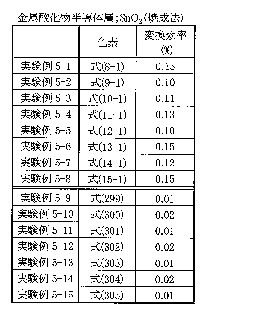
表5に示したように、金属酸化物半導体層12が焼成法により形成されると共に酸化錫を含む場合においても、表2に示した結果と同様の結果が得られた。すなわち、色素13がフェナンスレン骨格を有する式(8-1)に示した化合物等を含む実験例5-1~5-8では、フェナンスレン骨格を含まない式(299)に示した化合物等を用いた実験例5
-9~5-15よりも変換効率が高くなった。 As shown in Table 5, when the metaloxide semiconductor layer 12 was formed by the firing method and contained tin oxide, the same results as those shown in Table 2 were obtained. That is, in Experimental Examples 5-1 to 5-8 in which the dye 13 includes the compound represented by the formula (8-1) having a phenanthrene skeleton, the compound represented by the formula (299) not including the phenanthrene skeleton was used. Experimental Example 5
Conversion efficiency was higher than -9 to 5-15.
-9~5-15よりも変換効率が高くなった。 As shown in Table 5, when the metal
Conversion efficiency was higher than -9 to 5-15.
この場合においても、実験例5-3と実験例5-4とを比較すると、式(1)においてアンカー基(-CH2 -CH2 -COOH)がY1およびY2の双方に導入されているシアニン化合物を用いた場合において、変換効率が高くなった。また、実験例5-2と実験例5-3、および実験例5-4と実験例5-6とを比較すると、式(1)においてR7,R8,R10およびR11のうちの少なくとも1つとして、ベンジル基が導入されているシアニン化合物を用いた場合において、変換効率がより高くなった。さらに、実験例5-5と実験例5-8とを比較すると、メチン鎖骨格にシアノ基が導入されたシアニン化合物を用いた場合において、変換効率がより高くなった。
Even in this case, when Experimental Example 5-3 and Experimental Example 5-4 are compared, cyanine in which an anchor group (—CH 2 —CH 2 —COOH) is introduced into both Y1 and Y2 in Formula (1) When the compound was used, the conversion efficiency increased. Further, comparing Experimental Example 5-2 with Experimental Example 5-3, and Experimental Example 5-4 with Experimental Example 5-6, in Formula (1), at least one of R7, R8, R10, and R11 In the case of using a cyanine compound into which a benzyl group was introduced, the conversion efficiency was higher. Further, comparing Experimental Example 5-5 and Experimental Example 5-8, the conversion efficiency was higher when a cyanine compound having a cyano group introduced into the methine chain skeleton was used.
これらのことから、金属酸化物半導体層12が焼成法により形成されると共に酸化錫を含む光電変換素子においても、以下のことが確認された。すなわち、色素13が式(1)に示したシアニン化合物を含むことにより、そのシアニン化合物の種類に依存することなく、変換効率を向上させることができる。この場合においても、式(1)に示したシアニン化合物において、Y1およびY2の双方がアンカー基であったり、R7,R8,R10およびR11のうちの少なくとも1つが式(2)に示した基であったり、または、メチン鎖骨格にシアノ基が導入されていれば、さらに高い変換効率を得ることができる。
From these facts, the following was also confirmed in the photoelectric conversion element in which the metal oxide semiconductor layer 12 was formed by the firing method and contained tin oxide. That is, by including the cyanine compound represented by the formula (1) in the dye 13, conversion efficiency can be improved without depending on the type of the cyanine compound. Even in this case, in the cyanine compound represented by the formula (1), both Y1 and Y2 are anchor groups, or at least one of R7, R8, R10 and R11 is a group represented by the formula (2). If the cyano group is introduced into the methine chain skeleton, higher conversion efficiency can be obtained.
また、上記した表2~表5に示した結果から、本実施例における光電変換素子では、色素13が式(1)に示したシアニン化合物を含むことにより、そのシアニン化合物の種類や、金属酸化物半導体層12の形成方法や、金属酸化物半導体材料の種類に依存することなく、変換効率が向上することが確認された。この場合、金属酸化物半導体材料として、酸化亜鉛を用いた場合(表2,表3参照)において、酸化チタンや酸化錫を用いた場合(表4、表5参照)よりも、変換効率がより高くなった。このことから、特に、金属酸化物半導体層12が酸化亜鉛を含むようにすれば、変換効率がより向上することが確認された。
Further, from the results shown in Tables 2 to 5 above, in the photoelectric conversion element in this example, when the dye 13 contains the cyanine compound represented by the formula (1), the type of the cyanine compound, the metal oxidation It was confirmed that the conversion efficiency was improved without depending on the method for forming the physical semiconductor layer 12 and the type of the metal oxide semiconductor material. In this case, when zinc oxide is used as the metal oxide semiconductor material (see Tables 2 and 3), the conversion efficiency is higher than when titanium oxide or tin oxide is used (see Tables 4 and 5). It became high. From this, it was confirmed that the conversion efficiency is further improved particularly when the metal oxide semiconductor layer 12 contains zinc oxide.
以上、実施の形態および実施例を挙げて本発明を説明したが、本発明は上記した実施の形態および実施例において説明した態様に限定されず、種々の変形が可能である。例えば、本発明の光電変換素子の使用用途は、必ずしも既に説明した用途に限らず、他の用途であってもよい。他の用途としては、例えば、光センサなどが挙げられる。
Although the present invention has been described with reference to the embodiments and examples, the present invention is not limited to the modes described in the above embodiments and examples, and various modifications can be made. For example, the usage application of the photoelectric conversion element of the present invention is not necessarily limited to the usage already described, and may be other usages. Other applications include, for example, an optical sensor.
Claims (17)
- 色素と、この色素を担持した担持体とを有する電極を備え、
前記色素は、式(1)で表されるシアニン化合物を含む
ことを特徴とする光電変換素子。

(R1およびR2は各々独立に水酸基、ニトロ基、シアノ基あるいはハロゲン原子、またはアルキル基、アルコキシ基、アリール基、アリールアルキル基あるいはそれらの誘導体であり、aおよびbは各々独立に0~4の整数である。R3~R6は各々独立に水素原子、水酸基、ニトロ基、シアノ基あるいはハロゲン原子、またはアルキル基、アルコキシ基、アリール基、アリールアルキル基あるいはそれらの誘導体であり、R3およびR4のうちの少なくとも一方とR5およびR6のうちの少なくとも一方とはそれぞれ脱離して二重結合を形成してもよいし、それぞれ連結して環構造を形成してもよい。X1は-C(R7)(R8)-で表される基、-N(R9)-で表される基、硫黄原子、酸素原子、セレン原子あるいはテルル原子であり、X2は-C(R10)(R11)-で表される基、-N(R12)-で表される基、硫黄原子、酸素原子、セレン原子あるいはテルル原子である。R7、R8、R10およびR11は各々独立に水素原子あるいは式(2)で表される基、または式(2)に示した基に該当するものを除く、アルキル基、アルコキシ基、アリール基、アリールアルキル基あるいはそれらの誘導体である。R9およびR12は各々独立に水素原子、水酸基、ニトロ基、シアノ基あるいはハロゲン原子、またはアルキル基、アルコキシ基、アリール基、アリールアルキル基あるいはそれらの誘導体である。Y1およびY2は各々独立にアンカー基、またはアルキル基、アルコキシ基、アリール基、アリールアルキル基あるいはそれらの誘導体であり、Y1およびY2のうちの少なくとも一方はアンカー基である。Qは炭素原子数1以上7以下のメチン鎖を骨格とする連結基である。Anp-はp価のアニオンであり、pは1あるいは2であり、qは電荷を中性に保つ係数である。)
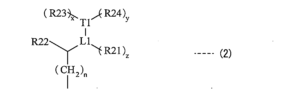
(L1とT1との間の結合は二重結合あるいは三重結合であり、L1は炭素原子を表し、T1は炭素原子、酸素原子あるいは窒素原子を表し、x、yおよびzは各々独立に0または1である(ただし、T1が酸素原子である場合にはxおよびyは0であり、T1が窒素原子の場合には(y+z)は0あるいは1である。)。R21~R23は各々独立に水素原子、水酸基、ニトロ基、シアノ基、ハロゲン原子、炭素原子数1以上4以下のアルキル基あるいは炭素原子数1以上4以下のハロゲン化アルキル基であり、R24は水素原子、水酸基、ニトロ基、シアノ基、ハロゲン原子、炭素原子数1以上4以下のアルキル基、炭素原子数1以上4以下のアルコキシ基、炭素原子数1以上4以下のハロゲン化アルキル基あるいは炭素原子数1以上4以下のハロゲン化アルコキシ基であり、R21とR24、R22とR23とはそれぞれ連結して環構造を形成してもよい。nは0以上4以下の整数である。) An electrode having a dye and a carrier carrying the dye;
The said pigment | dye contains the cyanine compound represented by Formula (1). The photoelectric conversion element characterized by the above-mentioned.
(R1 and R2 are each independently a hydroxyl group, a nitro group, a cyano group or a halogen atom, or an alkyl group, an alkoxy group, an aryl group, an arylalkyl group or a derivative thereof, and a and b are each independently 0-4. R3 to R6 are each independently a hydrogen atom, a hydroxyl group, a nitro group, a cyano group or a halogen atom, or an alkyl group, an alkoxy group, an aryl group, an arylalkyl group or a derivative thereof, and among R3 and R4, And at least one of R5 and R6 may be eliminated to form a double bond, or may be linked to form a ring structure, and X1 is —C (R7) ( A group represented by R8) —, a group represented by —N (R9) —, a sulfur atom, an oxygen atom, a selenium atom or a tellurium atom. , X2 is a group represented by —C (R10) (R11) —, a group represented by —N (R12) —, a sulfur atom, an oxygen atom, a selenium atom or a tellurium atom, R7, R8, R10 and R11 is each independently an alkyl group, an alkoxy group, an aryl group, an arylalkyl group or a derivative thereof except a hydrogen atom, a group represented by the formula (2), or a group corresponding to the group represented by the formula (2) R9 and R12 are each independently a hydrogen atom, a hydroxyl group, a nitro group, a cyano group or a halogen atom, or an alkyl group, an alkoxy group, an aryl group, an arylalkyl group, or a derivative thereof Y1 and Y2 are each independently Are an anchor group, an alkyl group, an alkoxy group, an aryl group, an arylalkyl group or a derivative thereof, and Y1 and At least one of the two is an anchor group .Q is an anion of .An p-p-valent is a linkage group that has a methine chain having 1 to 7 carbon atoms as a skeleton, p is 1 or 2 And q is a coefficient that keeps the charge neutral.)
(The bond between L1 and T1 is a double bond or a triple bond, L1 represents a carbon atom, T1 represents a carbon atom, an oxygen atom or a nitrogen atom, and x, y and z are each independently 0 or (However, when T1 is an oxygen atom, x and y are 0, and when T1 is a nitrogen atom, (y + z) is 0 or 1.) R21 to R23 are each independently A hydrogen atom, a hydroxyl group, a nitro group, a cyano group, a halogen atom, an alkyl group having 1 to 4 carbon atoms or a halogenated alkyl group having 1 to 4 carbon atoms, and R24 is a hydrogen atom, a hydroxyl group, a nitro group, A cyano group, a halogen atom, an alkyl group having 1 to 4 carbon atoms, an alkoxy group having 1 to 4 carbon atoms, a halogenated alkyl group having 1 to 4 carbon atoms, or 1 to 4 carbon atoms A halogenated alkoxy group of the lower, R21 and R24, R22 and may be to form a ring structure, respectively and R23 .n is zero or an integer of 4 or less.) - 前記式(1)に示したシアニン化合物は、式(3)で表される化合物である
ことを特徴とする請求項1記載の光電変換素子。
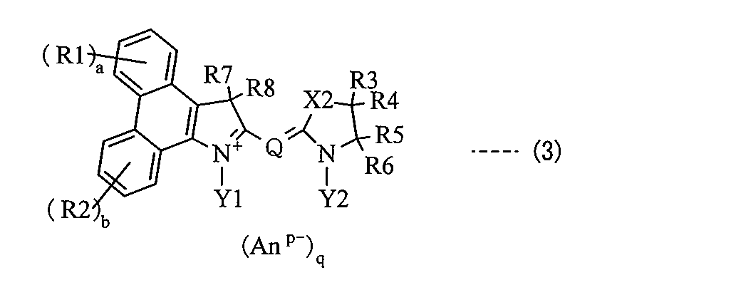
(R1およびR2は各々独立に水酸基、ニトロ基、シアノ基あるいはハロゲン原子、またはアルキル基、アルコキシ基、アリール基、アリールアルキル基あるいはそれらの誘導体であり、aおよびbは各々独立に0~4の整数である。R3~R6は各々独立に水素原子、水酸基、ニトロ基、シアノ基あるいはハロゲン原子、またはアルキル基、アルコキシ基、アリール基、アリールアルキル基あるいはそれらの誘導体であり、R3およびR4のうちの少なくとも一方とR5およびR6のうちの少なくとも一方とはそれぞれ脱離して二重結合を形成してもよいし、それぞれ連結して環構造を形成してもよい。X2は-C(R10)(R11)-で表される基、-N(R12)-で表される基、硫黄原子、酸素原子、セレン原子あるいはテルル原子である。R7、R8、R10およびR11は各々独立に水素原子あるいは式(2)で表される基、または式(2)に示した基に該当するものを除く、アルキル基、アルコキシ基、アリール基、アリールアルキル基あるいはそれらの誘導体である。R12は各々独立に水素原子、水酸基、ニトロ基、シアノ基あるいはハロゲン原子、またはアルキル基、アルコキシ基、アリール基、アリールアルキル基あるいはそれらの誘導体である。Y1およびY2は各々独立にアンカー基、またはアルキル基、アルコキシ基、アリール基、アリールアルキル基あるいはそれらの誘導体であり、Y1およびY2のうちの少なくとも一方はアンカー基である。Qは炭素原子数1以上7以下のメチン鎖を骨格とする連結基である。Anp-はp価のアニオンであり、pは1あるいは2であり、qは電荷を中性に保つ係数である。)

(L1とT1との間の結合は二重結合あるいは三重結合であり、L1は炭素原子を表し、T1は炭素原子、酸素原子あるいは窒素原子を表し、x、yおよびzは各々独立に0または1である(ただし、T1が酸素原子である場合にはxおよびyは0であり、T1が窒素原子の場合には(y+z)は0あるいは1である。)。R21~R23は各々独立に水素原子、水酸基、ニトロ基、シアノ基、ハロゲン原子、炭素原子数1以上4以下のアルキル基あるいは炭素原子数1以上4以下のハロゲン化アルキル基であり、R24は水素原子、水酸基、ニトロ基、シアノ基、ハロゲン原子、炭素原子数1以上4以下のアルキル基、炭素原子数1以上4以下のアルコキシ基、炭素原子数1以上4以下のハロゲン化アルキル基あるいは炭素原子数1以上4以下のハロゲン化アルコキシ基であり、R21とR24、R22とR23とはそれぞれ連結して環構造を形成してもよい。nは0以上4以下の整数である。) The photoelectric conversion element according to claim 1, wherein the cyanine compound represented by the formula (1) is a compound represented by the formula (3).
(R1 and R2 are each independently a hydroxyl group, a nitro group, a cyano group or a halogen atom, or an alkyl group, an alkoxy group, an aryl group, an arylalkyl group or a derivative thereof, and a and b are each independently 0-4. R3 to R6 are each independently a hydrogen atom, a hydroxyl group, a nitro group, a cyano group or a halogen atom, or an alkyl group, an alkoxy group, an aryl group, an arylalkyl group or a derivative thereof, and among R3 and R4, And at least one of R5 and R6 may be eliminated to form a double bond, or may be linked to form a ring structure, and X2 is —C (R10) ( R11) — group, —N (R12) — group, sulfur atom, oxygen atom, selenium atom or tellurium source R7, R8, R10 and R11 are each independently an alkyl group, an alkoxy group, an aryl group except for a hydrogen atom, a group represented by the formula (2), or a group corresponding to the group represented by the formula (2) R12 is independently a hydrogen atom, a hydroxyl group, a nitro group, a cyano group or a halogen atom, or an alkyl group, an alkoxy group, an aryl group, an arylalkyl group or a derivative thereof. Y1 and Y2 are each independently an anchor group, an alkyl group, an alkoxy group, an aryl group, an arylalkyl group or a derivative thereof, and at least one of Y1 and Y2 is an anchor group, Q is the number of carbon atoms Yes 1 or 7 of the following methine chain .An p-p-valent anion is a linking group to the backbone p is 1 or 2, q is a coefficient to maintain neutral electric charge.)
(The bond between L1 and T1 is a double bond or a triple bond, L1 represents a carbon atom, T1 represents a carbon atom, an oxygen atom or a nitrogen atom, and x, y and z are each independently 0 or (However, when T1 is an oxygen atom, x and y are 0, and when T1 is a nitrogen atom, (y + z) is 0 or 1.) R21 to R23 are each independently A hydrogen atom, a hydroxyl group, a nitro group, a cyano group, a halogen atom, an alkyl group having 1 to 4 carbon atoms or a halogenated alkyl group having 1 to 4 carbon atoms, and R24 is a hydrogen atom, a hydroxyl group, a nitro group, A cyano group, a halogen atom, an alkyl group having 1 to 4 carbon atoms, an alkoxy group having 1 to 4 carbon atoms, a halogenated alkyl group having 1 to 4 carbon atoms, or 1 to 4 carbon atoms A halogenated alkoxy group of the lower, R21 and R24, R22 and may be to form a ring structure, respectively and R23 .n is zero or an integer of 4 or less.) - 前記式(3)に示した化合物は、式(4)で表される化合物である
ことを特徴とする請求項2記載の光電変換素子。

(R1およびR2は各々独立に水酸基、ニトロ基、シアノ基あるいはハロゲン原子、またはアルキル基、アルコキシ基、アリール基、アリールアルキル基あるいはそれらの誘導体であり、aおよびbは各々独立に0~4の整数である。R7、R8、R10およびR11は各々独立に水素原子あるいは式(2)で表される基、または式(2)に示した基に該当するものを除く、アルキル基、アルコキシ基、アリール基、アリールアルキル基あるいはそれらの誘導体である。環Aはベンゼン環、ナフタレン環、フェナンスレン環あるいはそれらの誘導体である。Y1およびY2は各々独立にアンカー基、またはアルキル基、アルコキシ基、アリール基、アリールアルキル基あるいはそれらの誘導体であり、Y1およびY2のうちの少なくとも一方はアンカー基である。Qは炭素原子数1以上7以下のメチン鎖を骨格とする連結基である。Anp-はp価のアニオンであり、pは1あるいは2であり、qは電荷を中性に保つ係数である。)
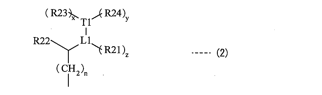
(L1とT1との間の結合は二重結合あるいは三重結合であり、L1は炭素原子を表し、T1は炭素原子、酸素原子あるいは窒素原子を表し、x、yおよびzは各々独立に0または1である(ただし、T1が酸素原子である場合にはxおよびyは0であり、T1が窒素原子の場合には(y+z)は0あるいは1である。)。R21~R23は各々独立に水素原子、水酸基、ニトロ基、シアノ基、ハロゲン原子、炭素原子数1以上4以下のアルキル基あるいは炭素原子数1以上4以下のハロゲン化アルキル基であり、R24は水素原子、水酸基、ニトロ基、シアノ基、ハロゲン原子、炭素原子数1以上4以下のアルキル基、炭素原子数1以上4以下のアルコキシ基、炭素原子数1以上4以下のハロゲン化アルキル基あるいは炭素原子数1以上4以下のハロゲン化アルコキシ基であり、R21とR24、R22とR23とはそれぞれ連結して環構造を形成してもよい。nは0以上4以下の整数である。) The photoelectric conversion element according to claim 2, wherein the compound represented by the formula (3) is a compound represented by the formula (4).
(R1 and R2 are each independently a hydroxyl group, a nitro group, a cyano group or a halogen atom, or an alkyl group, an alkoxy group, an aryl group, an arylalkyl group or a derivative thereof, and a and b are each independently 0-4. R7, R8, R10 and R11 are each independently a hydrogen atom or a group represented by the formula (2), or an alkyl group, an alkoxy group other than those corresponding to the group shown in the formula (2), An aryl group, an arylalkyl group, or a derivative thereof Ring A is a benzene ring, a naphthalene ring, a phenanthrene ring, or a derivative thereof Y1 and Y2 are each independently an anchor group, an alkyl group, an alkoxy group, or an aryl group , An arylalkyl group or a derivative thereof, and at least one of Y1 and Y2 An anchor group .Q is .An p-p-valent anion is a linkage group that has a methine chain of 1 to 7 carbon atoms as a skeleton, p is 1 or 2, q is a medium charge It is a coefficient to keep the sex.
(The bond between L1 and T1 is a double bond or a triple bond, L1 represents a carbon atom, T1 represents a carbon atom, an oxygen atom or a nitrogen atom, and x, y and z are each independently 0 or (However, when T1 is an oxygen atom, x and y are 0, and when T1 is a nitrogen atom, (y + z) is 0 or 1.) R21 to R23 are each independently A hydrogen atom, a hydroxyl group, a nitro group, a cyano group, a halogen atom, an alkyl group having 1 to 4 carbon atoms or a halogenated alkyl group having 1 to 4 carbon atoms, and R24 is a hydrogen atom, a hydroxyl group, a nitro group, A cyano group, a halogen atom, an alkyl group having 1 to 4 carbon atoms, an alkoxy group having 1 to 4 carbon atoms, a halogenated alkyl group having 1 to 4 carbon atoms, or 1 to 4 carbon atoms A halogenated alkoxy group of the lower, R21 and R24, R22 and may be to form a ring structure, respectively and R23 .n is zero or an integer of 4 or less.) - 前記式(4)に示した化合物は、式(5)で表される化合物である
ことを特徴とする請求項3記載の光電変換素子。

(R1、R2、R13およびR14は各々独立に水酸基、ニトロ基、シアノ基あるいはハロゲン原子、またはアルキル基、アルコキシ基、アリール基、アリールアルキル基あるいはそれらの誘導体であり、a~dは各々独立に0~4の整数である。R7、R8、R10およびR11は各々独立に水素原子あるいは式(2)で表される基、または式(2)に示した基に該当するものを除く、アルキル基、アルコキシ基、アリール基、アリールアルキル基あるいはそれらの誘導体である。Y1およびY2は各々独立にアンカー基、またはアルキル基、アルコキシ基、アリール基、アリールアルキル基あるいはそれらの誘導体であり、Y1およびY2のうちの少なくとも一方はアンカー基である。Qは炭素原子数1以上7以下のメチン鎖を骨格とする連結基である。Anp-はp価のアニオンであり、pは1あるいは2であり、qは電荷を中性に保つ係数である。)

(L1とT1との間の結合は二重結合あるいは三重結合であり、L1は炭素原子を表し、T1は炭素原子、酸素原子あるいは窒素原子を表し、x、yおよびzは各々独立に0または1である(ただし、T1が酸素原子である場合にはxおよびyは0であり、T1が窒素原子の場合には(y+z)は0あるいは1である。)。R21~R23は各々独立に水素原子、水酸基、ニトロ基、シアノ基、ハロゲン原子、炭素原子数1以上4以下のアルキル基あるいは炭素原子数1以上4以下のハロゲン化アルキル基であり、R24は水素原子、水酸基、ニトロ基、シアノ基、ハロゲン原子、炭素原子数1以上4以下のアルキル基、炭素原子数1以上4以下のアルコキシ基、炭素原子数1以上4以下のハロゲン化アルキル基あるいは炭素原子数1以上4以下のハロゲン化アルコキシ基であり、R21とR24、R22とR23とはそれぞれ連結して環構造を形成してもよい。nは0以上4以下の整数である。) The compound shown in said Formula (4) is a compound represented by Formula (5). The photoelectric conversion element of Claim 3 characterized by the above-mentioned.
(R1, R2, R13 and R14 are each independently a hydroxyl group, a nitro group, a cyano group or a halogen atom, or an alkyl group, an alkoxy group, an aryl group, an arylalkyl group or a derivative thereof; R is an integer of 0 to 4. R7, R8, R10 and R11 are each independently an alkyl group other than a hydrogen atom, a group represented by the formula (2), or a group corresponding to the group represented by the formula (2) Y1 and Y2 are each independently an anchor group, an alkyl group, an alkoxy group, an aryl group, an arylalkyl group or a derivative thereof, and Y1 and Y2 At least one of them is an anchor group, and Q has a methine chain having 1 to 7 carbon atoms as a skeleton. A linking group .An p-is p-valent anion, p is 1 or 2, q is a coefficient to maintain neutral electric charge.)
(The bond between L1 and T1 is a double bond or a triple bond, L1 represents a carbon atom, T1 represents a carbon atom, an oxygen atom or a nitrogen atom, and x, y and z are each independently 0 or (However, when T1 is an oxygen atom, x and y are 0, and when T1 is a nitrogen atom, (y + z) is 0 or 1.) R21 to R23 are each independently A hydrogen atom, a hydroxyl group, a nitro group, a cyano group, a halogen atom, an alkyl group having 1 to 4 carbon atoms or a halogenated alkyl group having 1 to 4 carbon atoms, and R24 is a hydrogen atom, a hydroxyl group, a nitro group, A cyano group, a halogen atom, an alkyl group having 1 to 4 carbon atoms, an alkoxy group having 1 to 4 carbon atoms, a halogenated alkyl group having 1 to 4 carbon atoms, or 1 to 4 carbon atoms A halogenated alkoxy group of the lower, R21 and R24, R22 and may be to form a ring structure, respectively and R23 .n is zero or an integer of 4 or less.) - 前記R7、R8、R10およびR11のうちの少なくとも1つは、前記式(2)に示した基である
ことを特徴とする請求項1ないし請求項4のいずれか1項に記載の光電変換素子。 5. The photoelectric conversion element according to claim 1, wherein at least one of R 7, R 8, R 10, and R 11 is a group represented by the formula (2). . - 前記アンカー基は、-CH2 -CH2 -C(=O)-OHで表される基あるいは-CH2 -CH2-C(=O)-O-で表される基である
ことを特徴とする請求項1ないし請求項5のいずれか1項に記載の光電変換素子。 The anchor group is a group represented by —CH 2 —CH 2 —C (═O) —OH or a group represented by —CH 2 —CH 2 —C (═O) —O 2 —. The photoelectric conversion element according to any one of claims 1 to 5. - 前記Y1およびY2の双方がアンカー基である
ことを特徴とする請求項1ないし請求項6のいずれか1項に記載の光電変換素子。 Both the said Y1 and Y2 are anchor groups. The photoelectric conversion element of any one of Claim 1 thru | or 6 characterized by the above-mentioned. - 前記Qは、メチン鎖にシアノ基が導入された連結基である
ことを特徴とする請求項1ないし請求項7のいずれか1項に記載の光電変換素子。 The photoelectric conversion element according to any one of claims 1 to 7, wherein Q is a linking group in which a cyano group is introduced into a methine chain. - 前記担持体は、酸化亜鉛(ZnO)を含む
ことを特徴とする請求項1ないし請求項8のいずれか1項に記載の光電変換素子。 The photoelectric conversion element according to any one of claims 1 to 8, wherein the carrier includes zinc oxide (ZnO). - 式(1)で表されるシアニン構造を有する
ことを特徴とする光電変換素子用色素。
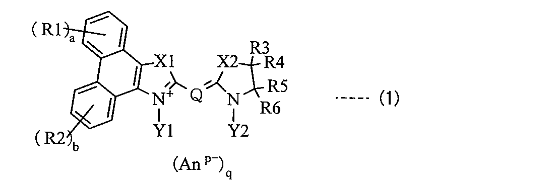
(R1およびR2は各々独立に水酸基、ニトロ基、シアノ基あるいはハロゲン原子、またはアルキル基、アルコキシ基、アリール基、アリールアルキル基あるいはそれらの誘導体であり、aおよびbは各々独立に0~4の整数である。R3~R6は各々独立に水素原子、水酸基、ニトロ基、シアノ基あるいはハロゲン原子、またはアルキル基、アルコキシ基、アリール基、アリールアルキル基あるいはそれらの誘導体であり、R3およびR4のうちの少なくとも一方とR5およびR6のうちの少なくとも一方とはそれぞれ脱離して二重結合を形成してもよいし、それぞれ連結して環構造を形成してもよい。X1は-C(R7)(R8)-で表される基、-N(R9)-で表される基、硫黄原子、酸素原子、セレン原子あるいはテルル原子であり、X2は-C(R10)(R11)-で表される基、-N(R12)-で表される基、硫黄原子、酸素原子、セレン原子あるいはテルル原子である。R7、R8、R10およびR11は各々独立に水素原子あるいは式(2)で表される基、または式(2)に示した基に該当するものを除く、アルキル基、アルコキシ基、アリール基、アリールアルキル基あるいはそれらの誘導体である。R9およびR12は各々独立に水素原子、水酸基、ニトロ基、シアノ基あるいはハロゲン原子、またはアルキル基、アルコキシ基、アリール基、アリールアルキル基あるいはそれらの誘導体である。Y1およびY2は各々独立にアンカー基、またはアルキル基、アルコキシ基、アリール基、アリールアルキル基あるいはそれらの誘導体であり、Y1およびY2のうちの少なくとも一方はアンカー基である。Qは炭素原子数1以上7以下のメチン鎖を骨格とする連結基である。Anp-はp価のアニオンであり、pは1あるいは2であり、qは電荷を中性に保つ係数である。)
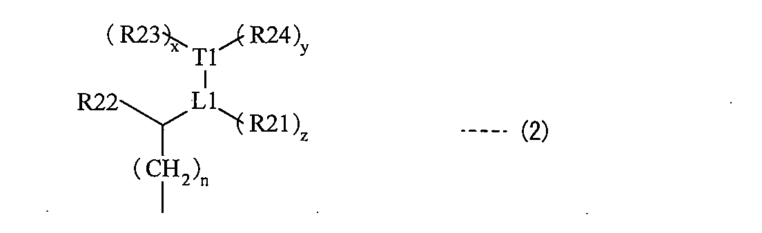
(L1とT1との間の結合は二重結合あるいは三重結合であり、L1は炭素原子を表し、T1は炭素原子、酸素原子あるいは窒素原子を表し、x、yおよびzは各々独立に0または1である(ただし、T1が酸素原子である場合にはxおよびyは0であり、T1が窒素原子の場合には(y+z)は0あるいは1である。)。R21~R23は各々独立に水素原子、水酸基、ニトロ基、シアノ基、ハロゲン原子、炭素原子数1以上4以下のアルキル基あるいは炭素原子数1以上4以下のハロゲン化アルキル基であり、R24は水素原子、水酸基、ニトロ基、シアノ基、ハロゲン原子、炭素原子数1以上4以下のアルキル基、炭素原子数1以上4以下のアルコキシ基、炭素原子数1以上4以下のハロゲン化アルキル基あるいは炭素原子数1以上4以下のハロゲン化アルコキシ基であり、R21とR24、R22とR23とはそれぞれ連結して環構造を形成してもよい。nは0以上4以下の整数である。) It has the cyanine structure represented by Formula (1). The pigment | dye for photoelectric conversion elements characterized by the above-mentioned.
(R1 and R2 are each independently a hydroxyl group, a nitro group, a cyano group or a halogen atom, or an alkyl group, an alkoxy group, an aryl group, an arylalkyl group or a derivative thereof, and a and b are each independently 0-4. R3 to R6 are each independently a hydrogen atom, a hydroxyl group, a nitro group, a cyano group or a halogen atom, or an alkyl group, an alkoxy group, an aryl group, an arylalkyl group or a derivative thereof, and among R3 and R4, And at least one of R5 and R6 may be eliminated to form a double bond, or may be linked to form a ring structure, and X1 is —C (R7) ( A group represented by R8) —, a group represented by —N (R9) —, a sulfur atom, an oxygen atom, a selenium atom or a tellurium atom. , X2 is a group represented by —C (R10) (R11) —, a group represented by —N (R12) —, a sulfur atom, an oxygen atom, a selenium atom or a tellurium atom, R7, R8, R10 and R11 is each independently an alkyl group, an alkoxy group, an aryl group, an arylalkyl group or a derivative thereof except a hydrogen atom, a group represented by the formula (2), or a group corresponding to the group represented by the formula (2) R9 and R12 are each independently a hydrogen atom, a hydroxyl group, a nitro group, a cyano group or a halogen atom, or an alkyl group, an alkoxy group, an aryl group, an arylalkyl group, or a derivative thereof Y1 and Y2 are each independently Are an anchor group, an alkyl group, an alkoxy group, an aryl group, an arylalkyl group or a derivative thereof, and Y1 and At least one of the two is an anchor group .Q is an anion of .An p-p-valent is a linkage group that has a methine chain having 1 to 7 carbon atoms as a skeleton, p is 1 or 2 And q is a coefficient that keeps the charge neutral.)
(The bond between L1 and T1 is a double bond or a triple bond, L1 represents a carbon atom, T1 represents a carbon atom, an oxygen atom or a nitrogen atom, and x, y and z are each independently 0 or (However, when T1 is an oxygen atom, x and y are 0, and when T1 is a nitrogen atom, (y + z) is 0 or 1.) R21 to R23 are each independently A hydrogen atom, a hydroxyl group, a nitro group, a cyano group, a halogen atom, an alkyl group having 1 to 4 carbon atoms or a halogenated alkyl group having 1 to 4 carbon atoms, and R24 is a hydrogen atom, a hydroxyl group, a nitro group, A cyano group, a halogen atom, an alkyl group having 1 to 4 carbon atoms, an alkoxy group having 1 to 4 carbon atoms, a halogenated alkyl group having 1 to 4 carbon atoms, or 1 to 4 carbon atoms A halogenated alkoxy group of the lower, R21 and R24, R22 and may be to form a ring structure, respectively and R23 .n is zero or an integer of 4 or less.) - 前記式(1)に示したシアニン構造は、式(3)で表される構造である
ことを特徴とする請求項10記載の光電変換素子用色素。

(R1およびR2は各々独立に水酸基、ニトロ基、シアノ基あるいはハロゲン原子、またはアルキル基、アルコキシ基、アリール基、アリールアルキル基あるいはそれらの誘導体であり、aおよびbは各々独立に0~4の整数である。R3~R6は各々独立に水素原子、水酸基、ニトロ基、シアノ基あるいはハロゲン原子、またはアルキル基、アルコキシ基、アリール基、アリールアルキル基あるいはそれらの誘導体であり、R3およびR4のうちの少なくとも一方とR5およびR6のうちの少なくとも一方とはそれぞれ脱離して二重結合を形成してもよいし、それぞれ連結して環構造を形成してもよい。X2は-C(R10)(R11)-で表される基、-N(R12)-で表される基、硫黄原子、酸素原子、セレン原子あるいはテルル原子である。R7、R8、R10およびR11は各々独立に水素原子あるいは式(2)で表される基、または式(2)に示した基に該当するものを除く、アルキル基、アルコキシ基、アリール基、アリールアルキル基あるいはそれらの誘導体である。R12は各々独立に水素原子、水酸基、ニトロ基、シアノ基あるいはハロゲン原子、またはアルキル基、アルコキシ基、アリール基、アリールアルキル基あるいはそれらの誘導体である。Y1およびY2は各々独立にアンカー基、またはアルキル基、アルコキシ基、アリール基、アリールアルキル基あるいはそれらの誘導体であり、Y1およびY2のうちの少なくとも一方はアンカー基である。Qは炭素原子数1以上7以下のメチン鎖を骨格とする連結基である。Anp-はp価のアニオンであり、pは1あるいは2であり、qは電荷を中性に保つ係数である。)

(L1とT1との間の結合は二重結合あるいは三重結合であり、L1は炭素原子を表し、T1は炭素原子、酸素原子あるいは窒素原子を表し、x、yおよびzは各々独立に0または1である(ただし、T1が酸素原子である場合にはxおよびyは0であり、T1が窒素原子の場合には(y+z)は0あるいは1である。)。R21~R23は各々独立に水素原子、水酸基、ニトロ基、シアノ基、ハロゲン原子、炭素原子数1以上4以下のアルキル基あるいは炭素原子数1以上4以下のハロゲン化アルキル基であり、R24は水素原子、水酸基、ニトロ基、シアノ基、ハロゲン原子、炭素原子数1以上4以下のアルキル基、炭素原子数1以上4以下のアルコキシ基、炭素原子数1以上4以下のハロゲン化アルキル基あるいは炭素原子数1以上4以下のハロゲン化アルコキシ基であり、R21とR24、R22とR23とはそれぞれ連結して環構造を形成してもよい。nは0以上4以下の整数である。) The dye for a photoelectric conversion element according to claim 10, wherein the cyanine structure represented by the formula (1) is a structure represented by the formula (3).
(R1 and R2 are each independently a hydroxyl group, a nitro group, a cyano group or a halogen atom, or an alkyl group, an alkoxy group, an aryl group, an arylalkyl group or a derivative thereof, and a and b are each independently 0-4. R3 to R6 are each independently a hydrogen atom, a hydroxyl group, a nitro group, a cyano group or a halogen atom, or an alkyl group, an alkoxy group, an aryl group, an arylalkyl group or a derivative thereof, and among R3 and R4, And at least one of R5 and R6 may be eliminated to form a double bond, or may be linked to form a ring structure, and X2 is —C (R10) ( R11) — group, —N (R12) — group, sulfur atom, oxygen atom, selenium atom or tellurium source R7, R8, R10 and R11 are each independently an alkyl group, an alkoxy group, an aryl group except for a hydrogen atom, a group represented by the formula (2), or a group corresponding to the group represented by the formula (2) R12 is independently a hydrogen atom, a hydroxyl group, a nitro group, a cyano group or a halogen atom, or an alkyl group, an alkoxy group, an aryl group, an arylalkyl group or a derivative thereof. Y1 and Y2 are each independently an anchor group, an alkyl group, an alkoxy group, an aryl group, an arylalkyl group or a derivative thereof, and at least one of Y1 and Y2 is an anchor group, Q is the number of carbon atoms Yes 1 or 7 of the following methine chain .An p-p-valent anion is a linking group to the backbone p is 1 or 2, q is a coefficient to maintain neutral electric charge.)
(The bond between L1 and T1 is a double bond or a triple bond, L1 represents a carbon atom, T1 represents a carbon atom, an oxygen atom or a nitrogen atom, and x, y and z are each independently 0 or (However, when T1 is an oxygen atom, x and y are 0, and when T1 is a nitrogen atom, (y + z) is 0 or 1.) R21 to R23 are each independently A hydrogen atom, a hydroxyl group, a nitro group, a cyano group, a halogen atom, an alkyl group having 1 to 4 carbon atoms or a halogenated alkyl group having 1 to 4 carbon atoms, and R24 is a hydrogen atom, a hydroxyl group, a nitro group, A cyano group, a halogen atom, an alkyl group having 1 to 4 carbon atoms, an alkoxy group having 1 to 4 carbon atoms, a halogenated alkyl group having 1 to 4 carbon atoms, or 1 to 4 carbon atoms A halogenated alkoxy group of the lower, R21 and R24, R22 and may be to form a ring structure, respectively and R23 .n is zero or an integer of 4 or less.) - 前記式(3)に示した構造は、式(4)で表される構造である
ことを特徴とする請求項11記載の光電変換素子用色素。

(R1およびR2は各々独立に水酸基、ニトロ基、シアノ基あるいはハロゲン原子、またはアルキル基、アルコキシ基、アリール基、アリールアルキル基あるいはそれらの誘導体であり、aおよびbは各々独立に0~4の整数である。R7、R8、R10およびR11は各々独立に水素原子あるいは式(2)で表される基、または式(2)に示した基に該当するものを除く、アルキル基、アルコキシ基、アリール基、アリールアルキル基あるいはそれらの誘導体である。環Aはベンゼン環、ナフタレン環、フェナンスレン環あるいはそれらの誘導体である。Y1およびY2は各々独立にアンカー基、またはアルキル基、アルコキシ基、アリール基、アリールアルキル基あるいはそれらの誘導体であり、Y1およびY2のうちの少なくとも一方はアンカー基である。Qは炭素原子数1以上7以下のメチン鎖を骨格とする連結基である。Anp-はp価のアニオンであり、pは1あるいは2であり、qは電荷を中性に保つ係数である。)

(L1とT1との間の結合は二重結合あるいは三重結合であり、L1は炭素原子を表し、T1は炭素原子、酸素原子あるいは窒素原子を表し、x、yおよびzは各々独立に0または1である(ただし、T1が酸素原子である場合にはxおよびyは0であり、T1が窒素原子の場合には(y+z)は0あるいは1である。)。R21~R23は各々独立に水素原子、水酸基、ニトロ基、シアノ基、ハロゲン原子、炭素原子数1以上4以下のアルキル基あるいは炭素原子数1以上4以下のハロゲン化アルキル基であり、R24は水素原子、水酸基、ニトロ基、シアノ基、ハロゲン原子、炭素原子数1以上4以下のアルキル基、炭素原子数1以上4以下のアルコキシ基、炭素原子数1以上4以下のハロゲン化アルキル基あるいは炭素原子数1以上4以下のハロゲン化アルコキシ基であり、R21とR24、R22とR23とはそれぞれ連結して環構造を形成してもよい。nは0以上4以下の整数である。) The structure shown in said Formula (3) is a structure represented by Formula (4). The pigment | dye for photoelectric conversion elements of Claim 11 characterized by the above-mentioned.
(R1 and R2 are each independently a hydroxyl group, a nitro group, a cyano group or a halogen atom, or an alkyl group, an alkoxy group, an aryl group, an arylalkyl group or a derivative thereof, and a and b are each independently 0-4. R7, R8, R10 and R11 are each independently a hydrogen atom or a group represented by the formula (2), or an alkyl group, an alkoxy group other than those corresponding to the group shown in the formula (2), An aryl group, an arylalkyl group, or a derivative thereof Ring A is a benzene ring, a naphthalene ring, a phenanthrene ring, or a derivative thereof Y1 and Y2 are each independently an anchor group, an alkyl group, an alkoxy group, or an aryl group , An arylalkyl group or a derivative thereof, and at least one of Y1 and Y2 An anchor group .Q is .An p-p-valent anion is a linkage group that has a methine chain of 1 to 7 carbon atoms as a skeleton, p is 1 or 2, q is a medium charge It is a coefficient to keep the sex.
(The bond between L1 and T1 is a double bond or a triple bond, L1 represents a carbon atom, T1 represents a carbon atom, an oxygen atom or a nitrogen atom, and x, y and z are each independently 0 or (However, when T1 is an oxygen atom, x and y are 0, and when T1 is a nitrogen atom, (y + z) is 0 or 1.) R21 to R23 are each independently A hydrogen atom, a hydroxyl group, a nitro group, a cyano group, a halogen atom, an alkyl group having 1 to 4 carbon atoms or a halogenated alkyl group having 1 to 4 carbon atoms, and R24 is a hydrogen atom, a hydroxyl group, a nitro group, A cyano group, a halogen atom, an alkyl group having 1 to 4 carbon atoms, an alkoxy group having 1 to 4 carbon atoms, a halogenated alkyl group having 1 to 4 carbon atoms, or 1 to 4 carbon atoms A halogenated alkoxy group of the lower, R21 and R24, R22 and may be to form a ring structure, respectively and R23 .n is zero or an integer of 4 or less.) - 前記式(4)に示した構造は、式(5)で表される構造である
ことを特徴とする請求項12記載の光電変換素子用色素。

(R1、R2、R13およびR14は各々独立に水酸基、ニトロ基、シアノ基あるいはハロゲン原子、またはアルキル基、アルコキシ基、アリール基、アリールアルキル基あるいはそれらの誘導体であり、a~dは各々独立に0~4の整数である。R7、R8、R10およびR11は各々独立に水素原子あるいは式(2)で表される基、または式(2)に示した基に該当するものを除く、アルキル基、アルコキシ基、アリール基、アリールアルキル基あるいはそれらの誘導体である。Y1およびY2は各々独立にアンカー基、またはアルキル基、アルコキシ基、アリール基、アリールアルキル基あるいはそれらの誘導体であり、Y1およびY2のうちの少なくとも一方はアンカー基である。Qは炭素原子数1以上7以下のメチン鎖を骨格とする連結基である。Anp-はp価のアニオンであり、pは1あるいは2であり、qは電荷を中性に保つ係数である。)
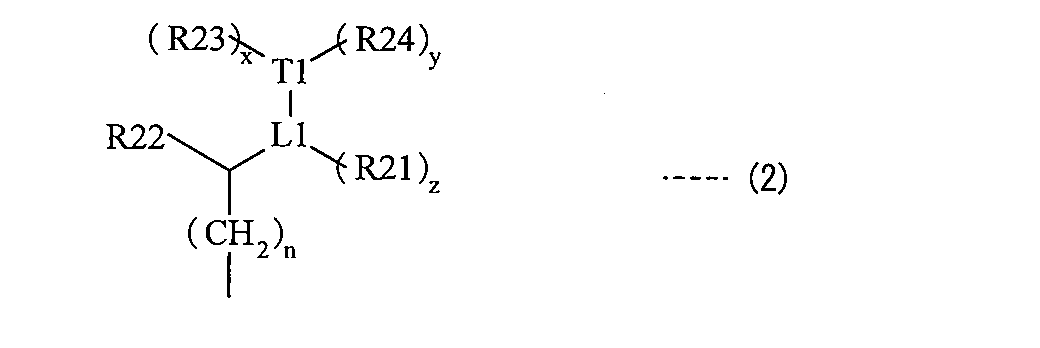
(L1とT1との間の結合は二重結合あるいは三重結合であり、L1は炭素原子を表し、T1は炭素原子、酸素原子あるいは窒素原子を表し、x、yおよびzは各々独立に0または1である(ただし、T1が酸素原子である場合にはxおよびyは0であり、T1が窒素原子の場合には(y+z)は0あるいは1である。)。R21~R23は各々独立に水素原子、水酸基、ニトロ基、シアノ基、ハロゲン原子、炭素原子数1以上4以下のアルキル基あるいは炭素原子数1以上4以下のハロゲン化アルキル基であり、R24は水素原子、水酸基、ニトロ基、シアノ基、ハロゲン原子、炭素原子数1以上4以下のアルキル基、炭素原子数1以上4以下のアルコキシ基、炭素原子数1以上4以下のハロゲン化アルキル基あるいは炭素原子数1以上4以下のハロゲン化アルコキシ基であり、R21とR24、R22とR23とはそれぞれ連結して環構造を形成してもよい。nは0以上4以下の整数である。) The structure shown in said Formula (4) is a structure represented by Formula (5). The pigment | dye for photoelectric conversion elements of Claim 12 characterized by the above-mentioned.
(R1, R2, R13 and R14 are each independently a hydroxyl group, a nitro group, a cyano group or a halogen atom, or an alkyl group, an alkoxy group, an aryl group, an arylalkyl group or a derivative thereof; R is an integer of 0 to 4. R7, R8, R10 and R11 are each independently an alkyl group other than a hydrogen atom, a group represented by the formula (2), or a group corresponding to the group represented by the formula (2) Y1 and Y2 are each independently an anchor group, an alkyl group, an alkoxy group, an aryl group, an arylalkyl group or a derivative thereof, and Y1 and Y2 At least one of them is an anchor group, and Q has a methine chain having 1 to 7 carbon atoms as a skeleton. A linking group .An p-is p-valent anion, p is 1 or 2, q is a coefficient to maintain neutral electric charge.)
(The bond between L1 and T1 is a double bond or a triple bond, L1 represents a carbon atom, T1 represents a carbon atom, an oxygen atom or a nitrogen atom, and x, y and z are each independently 0 or (However, when T1 is an oxygen atom, x and y are 0, and when T1 is a nitrogen atom, (y + z) is 0 or 1.) R21 to R23 are each independently A hydrogen atom, a hydroxyl group, a nitro group, a cyano group, a halogen atom, an alkyl group having 1 to 4 carbon atoms or a halogenated alkyl group having 1 to 4 carbon atoms, and R24 is a hydrogen atom, a hydroxyl group, a nitro group, A cyano group, a halogen atom, an alkyl group having 1 to 4 carbon atoms, an alkoxy group having 1 to 4 carbon atoms, a halogenated alkyl group having 1 to 4 carbon atoms, or 1 to 4 carbon atoms A halogenated alkoxy group of the lower, R21 and R24, R22 and may be to form a ring structure, respectively and R23 .n is zero or an integer of 4 or less.) - 前記R7、R8、R10およびR11のうちの少なくとも1つは、前記式(2)に示した基である
ことを特徴とする請求項10ないし請求項13のいずれか1項に記載の光電変換素子用色素。 14. The photoelectric conversion element according to claim 10, wherein at least one of R 7, R 8, R 10, and R 11 is a group represented by the formula (2). Dye for use. - 前記アンカー基は、-CH2 -CH2 -C(=O)-OHで表される基あるいは-CH2 -CH2-C(=O)-O-で表される基である
ことを特徴とする請求項10ないし請求項14のいずれか1項に記載の光電変換素子用色素。 The anchor group is a group represented by —CH 2 —CH 2 —C (═O) —OH or a group represented by —CH 2 —CH 2 —C (═O) —O 2 —. The pigment | dye for photoelectric conversion elements of any one of Claim 10 thru | or 14. - 前記Y1およびY2の双方がアンカー基である
ことを特徴とする請求項10ないし請求項15のいずれか1項に記載の光電変換素子用色素。 Both the said Y1 and Y2 are anchor groups. The pigment | dye for photoelectric conversion elements of any one of Claim 10 thru | or 15 characterized by the above-mentioned. - 前記Qは、メチン鎖にシアノ基が導入された連結基である
ことを特徴とする請求項10ないし請求項16のいずれか1項に記載の光電変換素子用色素。 The dye for a photoelectric conversion element according to any one of claims 10 to 16, wherein Q is a linking group in which a cyano group is introduced into a methine chain.
Priority Applications (3)
| Application Number | Priority Date | Filing Date | Title |
|---|---|---|---|
| CN200980152843.0A CN102265454B (en) | 2008-12-26 | 2009-12-25 | Pigment for use with photoelectric conversion element, and photoelectric conversion element |
| EP09834999.6A EP2372829B1 (en) | 2008-12-26 | 2009-12-25 | Pigment for use with photoelectric conversion element, and photoelectric conversion element |
| US13/141,993 US8912344B2 (en) | 2008-12-26 | 2009-12-25 | Dye for photoelectric conversion device and photoelectric conversion device |
Applications Claiming Priority (2)
| Application Number | Priority Date | Filing Date | Title |
|---|---|---|---|
| JP2008-333597 | 2008-12-26 | ||
| JP2008333597A JP5250412B2 (en) | 2008-12-26 | 2008-12-26 | Dye for photoelectric conversion element and photoelectric conversion element |
Publications (1)
| Publication Number | Publication Date |
|---|---|
| WO2010074203A1 true WO2010074203A1 (en) | 2010-07-01 |
Family
ID=42287808
Family Applications (1)
| Application Number | Title | Priority Date | Filing Date |
|---|---|---|---|
| PCT/JP2009/071547 WO2010074203A1 (en) | 2008-12-26 | 2009-12-25 | Pigment for use with photoelectric conversion element, and photoelectric conversion element |
Country Status (5)
| Country | Link |
|---|---|
| US (1) | US8912344B2 (en) |
| EP (1) | EP2372829B1 (en) |
| JP (1) | JP5250412B2 (en) |
| CN (1) | CN102265454B (en) |
| WO (1) | WO2010074203A1 (en) |
Cited By (1)
| Publication number | Priority date | Publication date | Assignee | Title |
|---|---|---|---|---|
| EP2621599A1 (en) * | 2010-09-27 | 2013-08-07 | The Technical University of Denmark | Improved electron transport layer |
Families Citing this family (8)
| Publication number | Priority date | Publication date | Assignee | Title |
|---|---|---|---|---|
| US8884029B2 (en) * | 2008-09-30 | 2014-11-11 | Adeka Corporation | Dye for photoelectric conversion device and photoelectric conversion device |
| JP5583990B2 (en) * | 2010-02-26 | 2014-09-03 | 株式会社Adeka | Photoelectric conversion element and dye for photoelectric conversion element |
| JP5894372B2 (en) * | 2010-11-01 | 2016-03-30 | パナソニック株式会社 | OPTOELECTRIC ELEMENT AND METHOD FOR PRODUCING OPTOELECTRIC ELEMENT |
| US20130180577A1 (en) * | 2012-01-18 | 2013-07-18 | Semiconductor Energy Laboratory Co., Ltd. | Photoelectric conversion device |
| KR20140138749A (en) * | 2012-03-30 | 2014-12-04 | 가부시키가이샤 아데카 | Dye-sensitized solar cell and method of manufacturing same |
| US20150380171A1 (en) * | 2012-12-28 | 2015-12-31 | Adeka Corporation | Carrier system and photoelectric conversion device |
| CN105340037B (en) * | 2013-08-29 | 2018-04-27 | 株式会社艾迪科 | dye-sensitized solar cell |
| KR102345977B1 (en) * | 2014-08-26 | 2021-12-30 | 삼성전자주식회사 | Organic photoelectronic device and image sensor |
Citations (8)
| Publication number | Priority date | Publication date | Assignee | Title |
|---|---|---|---|---|
| JPS60205841A (en) * | 1984-03-30 | 1985-10-17 | Tdk Corp | Optical recording medium |
| JPH02264937A (en) * | 1989-04-05 | 1990-10-29 | Mitsubishi Paper Mills Ltd | Silver halide photographic sensitive material |
| JPH08259543A (en) | 1994-12-21 | 1996-10-08 | Asulab Sa | Hydrophobic liquid salt,forming method for it,and its use inelectrochemistry |
| JPH09507334A (en) | 1993-02-03 | 1997-07-22 | エコール ポリテクニーク フェデラル ドゥ ローザンヌ | Photoelectrochemical cell and electrolyte for this cell |
| JP2007220412A (en) | 2006-02-15 | 2007-08-30 | Gifu Univ | Sensitizing dye used for dye-sensitized photoelectric conversion element and dye-sensitized solar cell using sensitizing dye |
| JP2008166119A (en) | 2006-12-28 | 2008-07-17 | Tdk Corp | Photoelectric conversion element |
| JP2008274230A (en) | 2007-03-30 | 2008-11-13 | Adeka Corp | Cyanine compound and optical filter and optical recording material using the compound |
| JP2008277268A (en) * | 2007-03-30 | 2008-11-13 | Tdk Corp | Photoelectric conversion element |
Family Cites Families (3)
| Publication number | Priority date | Publication date | Assignee | Title |
|---|---|---|---|---|
| JP2000294303A (en) * | 1999-04-02 | 2000-10-20 | Fuji Photo Film Co Ltd | Photoelectric converting element and photoelectric chemical battery |
| US6359211B1 (en) * | 1999-06-17 | 2002-03-19 | Chemmotif, Inc. | Spectral sensitization of nanocrystalline solar cells |
| US7943849B2 (en) | 2007-03-30 | 2011-05-17 | Tdk Corporation | Photoelectric conversion device |
-
2008
- 2008-12-26 JP JP2008333597A patent/JP5250412B2/en not_active Expired - Fee Related
-
2009
- 2009-12-25 US US13/141,993 patent/US8912344B2/en not_active Expired - Fee Related
- 2009-12-25 EP EP09834999.6A patent/EP2372829B1/en not_active Not-in-force
- 2009-12-25 WO PCT/JP2009/071547 patent/WO2010074203A1/en active Application Filing
- 2009-12-25 CN CN200980152843.0A patent/CN102265454B/en not_active Expired - Fee Related
Patent Citations (8)
| Publication number | Priority date | Publication date | Assignee | Title |
|---|---|---|---|---|
| JPS60205841A (en) * | 1984-03-30 | 1985-10-17 | Tdk Corp | Optical recording medium |
| JPH02264937A (en) * | 1989-04-05 | 1990-10-29 | Mitsubishi Paper Mills Ltd | Silver halide photographic sensitive material |
| JPH09507334A (en) | 1993-02-03 | 1997-07-22 | エコール ポリテクニーク フェデラル ドゥ ローザンヌ | Photoelectrochemical cell and electrolyte for this cell |
| JPH08259543A (en) | 1994-12-21 | 1996-10-08 | Asulab Sa | Hydrophobic liquid salt,forming method for it,and its use inelectrochemistry |
| JP2007220412A (en) | 2006-02-15 | 2007-08-30 | Gifu Univ | Sensitizing dye used for dye-sensitized photoelectric conversion element and dye-sensitized solar cell using sensitizing dye |
| JP2008166119A (en) | 2006-12-28 | 2008-07-17 | Tdk Corp | Photoelectric conversion element |
| JP2008274230A (en) | 2007-03-30 | 2008-11-13 | Adeka Corp | Cyanine compound and optical filter and optical recording material using the compound |
| JP2008277268A (en) * | 2007-03-30 | 2008-11-13 | Tdk Corp | Photoelectric conversion element |
Non-Patent Citations (3)
| Title |
|---|
| ELECTROCHEMISTRY, vol. 2, 2002, pages 130 - 136 |
| INORG. CHEM., vol. 35, 1996, pages 1168 - 1178 |
| See also references of EP2372829A4 |
Cited By (1)
| Publication number | Priority date | Publication date | Assignee | Title |
|---|---|---|---|---|
| EP2621599A1 (en) * | 2010-09-27 | 2013-08-07 | The Technical University of Denmark | Improved electron transport layer |
Also Published As
| Publication number | Publication date |
|---|---|
| EP2372829A1 (en) | 2011-10-05 |
| JP2010157373A (en) | 2010-07-15 |
| CN102265454B (en) | 2014-04-30 |
| EP2372829A4 (en) | 2012-08-08 |
| US8912344B2 (en) | 2014-12-16 |
| EP2372829B1 (en) | 2015-08-19 |
| US20110253218A1 (en) | 2011-10-20 |
| CN102265454A (en) | 2011-11-30 |
| JP5250412B2 (en) | 2013-07-31 |
Similar Documents
| Publication | Publication Date | Title |
|---|---|---|
| JP5250412B2 (en) | Dye for photoelectric conversion element and photoelectric conversion element | |
| US9424999B2 (en) | Dye for photoelectric conversion device and photoelectric conversion device | |
| JP5267846B2 (en) | Photoelectric conversion element | |
| JP6145407B2 (en) | Novel compound and carrier carrying the novel compound | |
| WO2014103831A1 (en) | Loaded body and photoelectric conversion element | |
| JP5669508B2 (en) | Photoelectric conversion element, dye for photoelectric conversion element, and compound | |
| JP5401193B2 (en) | Dye for photoelectric conversion element and photoelectric conversion element | |
| JP6113713B2 (en) | Novel compound and carrier carrying the novel compound | |
| JP5914462B2 (en) | Novel compound and photoelectric conversion element | |
| JP5412955B2 (en) | Electrode and photoelectric conversion element | |
| JP2008247997A (en) | Pigment, photoelectric transducer using the same, and method for manufacturing the photoelectric transducer | |
| US10141118B2 (en) | Carrier system and photoelectric conversion device | |
| JP2016219653A (en) | Support material and photoelectric conversion element |
Legal Events
| Date | Code | Title | Description |
|---|---|---|---|
| WWE | Wipo information: entry into national phase |
Ref document number: 200980152843.0 Country of ref document: CN |
|
| 121 | Ep: the epo has been informed by wipo that ep was designated in this application |
Ref document number: 09834999 Country of ref document: EP Kind code of ref document: A1 |
|
| WWE | Wipo information: entry into national phase |
Ref document number: 13141993 Country of ref document: US Ref document number: 2009834999 Country of ref document: EP |
|
| NENP | Non-entry into the national phase |
Ref country code: DE |