WO2010071385A2 - Procédé de réception d'informations de commande et terminal utilisant ce procédé - Google Patents
Procédé de réception d'informations de commande et terminal utilisant ce procédé Download PDFInfo
- Publication number
- WO2010071385A2 WO2010071385A2 PCT/KR2009/007635 KR2009007635W WO2010071385A2 WO 2010071385 A2 WO2010071385 A2 WO 2010071385A2 KR 2009007635 W KR2009007635 W KR 2009007635W WO 2010071385 A2 WO2010071385 A2 WO 2010071385A2
- Authority
- WO
- WIPO (PCT)
- Prior art keywords
- map
- broadcast message
- user specific
- specific
- scheduling information
- Prior art date
Links
Images


Classifications
-
- H—ELECTRICITY
- H04—ELECTRIC COMMUNICATION TECHNIQUE
- H04L—TRANSMISSION OF DIGITAL INFORMATION, e.g. TELEGRAPHIC COMMUNICATION
- H04L5/00—Arrangements affording multiple use of the transmission path
- H04L5/003—Arrangements for allocating sub-channels of the transmission path
- H04L5/0053—Allocation of signaling, i.e. of overhead other than pilot signals
-
- H—ELECTRICITY
- H04—ELECTRIC COMMUNICATION TECHNIQUE
- H04W—WIRELESS COMMUNICATION NETWORKS
- H04W72/00—Local resource management
- H04W72/12—Wireless traffic scheduling
- H04W72/1263—Mapping of traffic onto schedule, e.g. scheduled allocation or multiplexing of flows
- H04W72/1273—Mapping of traffic onto schedule, e.g. scheduled allocation or multiplexing of flows of downlink data flows
-
- H—ELECTRICITY
- H04—ELECTRIC COMMUNICATION TECHNIQUE
- H04W—WIRELESS COMMUNICATION NETWORKS
- H04W48/00—Access restriction; Network selection; Access point selection
- H04W48/08—Access restriction or access information delivery, e.g. discovery data delivery
- H04W48/12—Access restriction or access information delivery, e.g. discovery data delivery using downlink control channel
-
- H—ELECTRICITY
- H04—ELECTRIC COMMUNICATION TECHNIQUE
- H04W—WIRELESS COMMUNICATION NETWORKS
- H04W48/00—Access restriction; Network selection; Access point selection
- H04W48/16—Discovering, processing access restriction or access information
Definitions
- the present invention relates to a wireless communication system, and more particularly, to a method for receiving control information of a terminal.
- the downlink channel descriptor is a MAC management message for transmitting system information about a downlink channel, and the terminal may decode a DL burst after receiving the DCD.
- An uplink channel descriptor is a MAC management message that transmits system information on uplink. After receiving the UCD, the UE starts transmitting a signal through uplink.
- 'MOB-TRF-IND' is a MAC management message indicating whether there is downlink traffic to be delivered to the terminals in the sleep mode
- 'MOB-PAG-ADV' is to the terminals in the idle mode (idle mode) MAC management message indicating whether there is downlink traffic to be delivered.
- the 'MOB-NBR-ADV' is a message that informs the system information of neighboring base stations
- 'LBS-ADV' is a message that informs the location based service (LBS)
- SII-ADV Service Identity Information Advertisement
- the downlink control channels contain essential information necessary for the operation of the IEEE 802.16m system.
- Information on the downlink control channel is transmitted hierarchically on different time scales from the superframe level to the advanced air interface (AAI) subframe level.
- AAI advanced air interface
- the terminal may access the system without decoding the wireless MAN-OFDMA FCH and MAP messages.
- a super frame header which is one of the downlink control channels, is transmitted with essential system parameters and system configuration information.
- the superframe header is transmitted with the system information necessary for the terminal to enter the network.
- the superframe header includes a primary superframe header (P-SFH) and a secondary superframe header (S-SFH).
- P-SFH primary superframe header
- S-SFH secondary superframe header
- the main superframe header P-SCH
- S-SFH secondary superframe header
- the superframe header is also called a broadcast channel (BCH) (broadcast channel includes a main broadcast channel (P-BCH) and a sub-broadcast channel (S-BCH)) and may also be used in the same sense.
- BCH broadcast channel
- P-BCH main broadcast channel
- S-BCH sub-broadcast channel
- A-MAP Advanced MAP
- Unicast service control information is largely divided into user specific control information and non-user specific control information.
- the user-specific control information is divided into assignment information, HARQ feedback information, and power control information.
- the allocation information, the HARQ feedback information, and the power control information are transmitted to an assignment A-MAP, an HARQ feedback A-MAP, and a power control A-MAP, respectively.
- FIG. 1 is a diagram illustrating an example of a location where an A-MAP region is allocated in a frame structure of an IEEE 802.16m system.
- FIG. 1 illustrates an A-MAP allocation position for one frame in an IEEE 802.16m system.
- a ratio of the number of downlink subframes and the number of uplink subframes in one frame is 4: 4 in a frame structure using a time division duplex (TDD) scheme is described.
- All A-MAPs in this one frame share an area of a physical resource called an A-MAP area, and the A-MAP area is located in all downlink subframes.
- Downlink data corresponding to control information contained in the A-MAP region may be allocated to a resource region in a subframe located in the A-MAP region.
- FIG. 2 is a diagram illustrating the structure of an A-MAP region in an IEEE 802.16m system.
- the A-MAP region 210 includes a non-user specific A-MAP 220, a HARQ feedback A-MAP 230, a power control A-MAP 240, an allocation A-MAP 250. It includes.
- the non-user specific A-MAP Information Element (IE) is composed of information that is not assigned to a specific user or a specific group of users, that is, information transmitted to all terminals.
- the HARQ feedback A-MAP 230 includes control information regarding a retransmission request, and the power control A-MAP 240 is transmitted including power control information for uplink power control of the terminal.
- the assigned A-MAP IE includes information for decoding.
- the number of assigned A-MAPs in each assigned A-MAP group is specified in the non-user specific A-MAP IE 220.
- the allocation A-MAP 250 includes resource allocation information classified into various types of resource allocation IEs (allocation A-MAP IE).
- Each assigned A-MAP IE is individually coded and sent with information for one user or a group of users.
- the assigned A-MAP IE will be sent to the minimum LRUs composed of several in one minimum LRU (A-MAP area) A-MAP area 210.
- the number of logically contiguous MLRUs (LRUs) is determined based on the size of the allocation IE and the channel coding rate, and the channel coding rate is selected based on the link condition of the terminal.
- the assigned A-MAPs 250 are grouped together based on the Modulation and Coding Selection (MCS) level and the A-MAP IE size.
- MCS Modulation and Coding Selection
- Each assigned A-MAP group contains several logically contiguous minimum LRUs, and the number of assigned A-MAPs 250 in each assigned A-MAP group is conveyed by the non-user specific A-MAP 220.
- the A-MAP region 210 is composed of L AMAP distributed Logical Resource Units (LRUs), and the LRUs represent Nsym symbols. It is formed of Physical Resource Units (PRUs).
- LRUs Logical Resource Units
- PRUs Physical Resource Units
- the idle mode UE transmits a paging message from the A-MAP information shown in FIGS. 1 and 2, it is conventionally required to read scheduling information in every subframe during a paging listening interval. There was inconvenience.
- a sleep mode terminal also transmits a 'TRF-IND' (traffic indication) message, it is inconvenient to read scheduling information in every subframe during a sleep listening interval. .
- the allocation has a problem in that the overhead of decoding all scheduling information for the terminal increases significantly.
- An object of the present invention is to provide a method for receiving control information of a terminal.
- Another object of the present invention is to provide a terminal device for receiving control information.
- an indicator indicating that a non-user specific A-MAP IE is configured as an extended type as a broadcast message is transmitted in a specific subframe.
- Receiving from the base station a non-user specific A-MAP IE of the specific subframe comprising: obtaining scheduling information configured in the non-user specific A-MAP IE extension type based on the received indicator; Decoding the broadcast message in the specific subframe using the obtained scheduling information.
- a terminal device includes an indicator indicating that a non-user specific A-MAP IE is configured as an extended type as a broadcast message is transmitted in a specific subframe.
- a receiving module for receiving a non-user specific A-MAP IE of the specific subframe from a base station and a scheduling information obtaining module for obtaining scheduling information configured of the non-user specific A-MAP IE extension type based on the received indicator
- a decoding module for decoding the broadcast message in the specific subframe using the obtained scheduling information.
- a base station transmits a broadcast message indicator or a non-user specific A-MAP extension flag to a terminal in a non-user specific A-MAP in the A-MAP region, thereby transmitting a broadcast message in a current subframe. You can quickly see if it is being sent.
- FIG. 1 is a diagram illustrating an example of a location where an A-MAP region is allocated in a frame structure of an IEEE 802.16m system
- FIG. 2 is a diagram illustrating the structure of an A-MAP region in an IEEE 802.16m system
- FIG. 3 is a diagram illustrating an example of a process in which an active mode terminal receives a scheduling message (eg, assigned A-MAP IEs) using a broadcast message indicator included in a non-user specific A-MAP;
- a scheduling message eg, assigned A-MAP IEs
- FIG. 4 is a diagram illustrating an example of a process in which an idle mode terminal receives a broadcast message including a paging message using a broadcast message indicator included in a non-user specific A-MAP during its paging listening interval;
- FIG. 5 is a diagram illustrating a process in which a sleep mode terminal receives a broadcast message including a traffic indication message by using a broadcast message indicator included in a non-user specific A-MAP during its listening period;
- FIG. 6 illustrates an example of a non-user specific A-MAP structure including a broadcast message indicator
- FIG. 7 illustrates another example of a non-user specific A-MAP structure including a broadcast message indicator
- FIG. 8 is a diagram illustrating an example in which scheduling information for a broadcast message is transmitted in the form of an assigned A-MAP.
- FIG. 9 is a diagram illustrating a configuration of a preferred embodiment of a terminal device for performing the method for receiving control information according to the present invention.
- a terminal collectively refers to a mobile or fixed user terminal device such as an AMS (Advanced Mobile Station), a UE (User Equipment), or a MS (Mobile Station).
- the base station collectively refers to any node of the network side that communicates with the terminal such as a Node B, an eNode B, a Base Station, and an Access Point (AP).
- AMS Advanced Mobile Station
- UE User Equipment
- MS Mobile Station
- the base station collectively refers to any node of the network side that communicates with the terminal such as a Node B, an eNode B, a Base Station, and an Access Point (AP).
- AP Access Point
- a terminal may receive information from a base station through downlink, and the terminal may also transmit information through uplink.
- the information transmitted or received by the terminal includes data and various control information, and various physical channels exist according to the type and purpose of the information transmitted or received by the terminal.
- the AAI subframe used in the present invention refers to a structured data sequence of a predefined duration used by the Advanced Air Interface (AAI), and may also be generally referred to as a subframe.
- AAI Advanced Air Interface
- non-user specific A-MAP N-user specific A-MAP
- the non-user specific A-MAP may include a broadcast message indicator indicating whether a paging message, a traffic indication message, or other broadcast message is transmitted in a predetermined subframe.
- the base station may transmit a non-user specific A-MAP including a broadcast message indicator to the terminal in the downlink subframe to determine whether the broadcast message is transmitted in the current subframe.
- the term 'broadcast message indicator' used in the present invention may be used in other terms such as 'non-user specific A-MAP extension flag'. That is, the broadcast message indicator (or non-user specific A-MAP extension flag) may inform the terminal whether the non-user specific A-MAP is transmitted in the form of non-user specific A-MAP extension. More specifically, when the base station transmits a broadcast message in the current subframe, the broadcast message indicator included in the non-user specific A-MAP is set to a specific value (or the non-user specific A-MAP extension flag is Set), the base station is currently transmitting a broadcast message in a subframe, and the scheduling information for the broadcast message may mean that the non-user specific A-MAP extension is configured and transmitted.
- the terminal in the idle mode or the sleep mode state first checks whether the broadcast message indicator included in the non-user specific A-MAP in the specific subframe is set. As a result of the check, if the broadcast message indicator is set to 0, the terminal determines that a broadcast message including a paging message or a traffic indication message is not transmitted in the specific subframe, and reads the broadcast message in the specific subframe. You can stop and jump to the next subframe.
- the broadcast message indicator included in the non-user specific A-MAP indicates that the scheduling information for the broadcast message is specified in the specific subframe. Indicates that it is being transmitted in the A-MAP area of. For example, if the broadcast message indicator of the non-user specific A-MAP is set to 0, since the broadcast message is not transmitted in the current subframe, scheduling information for the broadcast message is included in the A-MAP area. Not sent.
- the scheduling information for the broadcast message includes resource allocation information for the broadcast message.
- Table 1 below shows an example of a non-user specific A-MAP IE according to the present invention.
- the base station may transmit a non-user specific A-MAP IE including a broadcast message indicator to the terminal.
- the broadcast message indicator included in the non-user specific A-MAP IE may be 1 bit in size.
- the broadcast message indicator may inform the terminal whether a broadcast message is transmitted through a current subframe. For example, if the broadcast message indicator is set to 0, the terminal may determine that a broadcast message is not being transmitted in the current subframe.
- FIG. 3 is a diagram illustrating an example of a process in which an active mode terminal receives a scheduling message (eg, assigned A-MAP IEs) using a broadcast message indicator included in a non-user specific A-MAP.
- a scheduling message eg, assigned A-MAP IEs
- an active mode terminal receives a non-user specific A-MAP region from a base station (S310), and then the active mode terminal displays a broadcast message indicator in the non-user specific A-MAP region. It is determined whether it is included (S320). If the transmitted non-user specific A-MAP includes a broadcast message indicator (for example, if the broadcast message indicator points to 1), the active mode terminal determines that the broadcast message is transmitted in the corresponding subframe and designates the location. In step S330, scheduling information for decoding the broadcast message is started to be read.
- the active mode terminal When the active mode terminal reads out scheduling information for decoding the broadcast message, a process of reading other scheduling information (for example, allocation A-MAP IEs (DL / UL basic A-MAP IE, GRA / PA A-MAP IEs, etc.) However, if the broadcast message indicator is not included in the transmitted non-user specific A-MAP (for example, when the broadcast message indicator is set to 0), the active mode terminal is performed in the corresponding subframe. When it is determined that the broadcast message is not transmitted, a process for immediately reading other scheduling information is performed without performing the task of reading scheduling information about the broadcast message (S340).
- allocation A-MAP IEs DL / UL basic A-MAP IE, GRA / PA A-MAP IEs, etc.
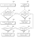
- FIG. 4 is a diagram illustrating an example of a process in which an idle mode terminal receives a broadcast message including a paging message using a broadcast message indicator included in a non-user specific A-MAP during its paging listening interval.
- the idle mode terminal receives the non-user specific A-MAP from the base station (S410).
- the idle mode terminal includes a broadcast message indicator in the non-user specific A-MAP (for example, a broadcast message indicator). Is set to 1) (S420). If the transmitted non-user specific A-MAP includes a broadcast message indicator (for example, if the broadcast message indicator is set to 1), the idle mode terminal reads scheduling information for decoding the broadcast message ( S430).
- the idle mode terminal checks whether a paging message exists in the broadcast message (S440). If the paging message exists in the broadcast message, the idle mode terminal performs a process of reading the paging message (S450). On the contrary, if the paging message does not exist in the broadcast message, the idle mode terminal checks whether there is another broadcast message (S460). If there is another broadcast message, a process of decoding other broadcast messages is performed (S470).
- the idle mode terminal transmits another broadcast message including a paging message in the corresponding subframe.
- operation S480 it is determined that the corresponding subframe is the last downlink subframe of the paging listening period. At this time, if the corresponding subframe is the last downlink subframe of the paging listening interval, the idle mode terminal waits for the next paging listening interval (S490).
- the UE moves to the next downlink subframe of the paging listening period and receives a non-user specific A-MAP for decoding the paging message again. (S495).
- FIG. 5 is a diagram illustrating a process in which a sleep mode terminal receives a broadcast message including a traffic indication message using a broadcast message indicator included in a non-user specific A-MAP during its listening period.
- the sleep mode terminal receives a non-user specific A-MAP from a base station (S510).
- the sleep mode terminal may include a broadcast message indicator in the non-user specific A-MAP (for example, It is set to 1) (S520). If the transmitted non-user specific A-MAP includes a broadcast message indicator (for example, if the broadcast message indicator is set to 1), the sleep mode terminal reads scheduling information for decoding the broadcast message ( S530).
- the sleep mode terminal checks whether a traffic indication message exists in the broadcast message (S540). If the traffic indication message exists in the broadcast message, the sleep mode terminal performs a process of reading the traffic indication message (AAI-TRF-IND) (S550). On the contrary, if the traffic indication message does not exist in the broadcast message, the sleep mode terminal checks whether there is another broadcast message (S560). If another broadcast message is further present, the terminal decodes another broadcast message (S570).
- the sleep mode UE may receive another broadcast message including a traffic indication message in the corresponding subframe. It is determined that the data is not transmitted to determine whether the corresponding subframe is the last downlink subframe of the listening period (S580). At this time, if the corresponding subframe is the last downlink subframe of the listening period, the sleep mode terminal waits for the next listening period (S590).
- the subframe moves to the next downlink subframe of the listening period, and receives a non-user specific A-MAP for decoding the traffic indication message again (S595). ).
- FIG. 6 is a diagram illustrating an example of a non-user specific A-MAP structure including a broadcast message indicator.
- the frame in which the idle mode terminal receives the paging message may be the fourth frame 610 in the paging listening period.
- the A-MAP region 620 of a specific subframe may be used to assign a non-user specific A-MAP 621, HARQ feedback A-MAP 622, a power control A-MAP 623, and assigned A-MAPs 624. Include.
- the broadcast message indicator is set to 0 in the non-user specific A-MAP 621, the broadcast message is not included in the corresponding subframe.
- the A-MAP region 620 does not include scheduling information (assigned A-MAP IE or other structure) for broadcast message transmission.
- the terminal in the idle mode or the sleep mode reads the non-user specific A-MAP 621 and knows that the broadcast message indicator is set to 0, so that the remaining A-MAP in the A-MAP area 620 is available. (Eg, HARQ feedback A-MAP 622, power control A-MAP 623, allocation A-MAPs 624). As shown in FIG.
- the idle mode terminal only once the non-user specific A-MAP 621. You can quickly read whether a broadcast message is sent by reading. Therefore, the idle mode UE can solve problems such as inefficient resource usage due to blind decoding of A-MAP.
- the UE can significantly reduce the overhead of decoding all of the specific subframes as it is indicated by searching whether the broadcast message is included in the A-MAP region in the specific subframe.
- FIG. 7 illustrates another example of a non-user specific A-MAP structure including a broadcast message indicator.
- the A-MAP region 710 of a specific subframe includes a non-user specific A-MAP 720, scheduling information 721 of a broadcast message, HARQ feedback A-MAP 722, and power control A. -MAP 723, assignment A-MAP 724, broadcast message 730 and downlink burst 740.
- the broadcast message indicator is set to 1, for example, this means that the broadcast message is transmitted in the current subframe.
- the A-MAP region 710 of the corresponding subframe includes scheduling information for broadcast message transmission.
- the broadcast message 730 may be located after the allocation A-MAPs 724 or in front of the downlink bursts 740.
- scheduling information 721 of the broadcast message may be located behind the non-user specific A-MAP 720.
- the scheduling information 721 for broadcast message transmission may be configured as an extended type of the non-user specific A-MAP 720 or may be configured as an independent type. Configuring extended type here is the same physical structure as the non-user specific A-MAP 720 (e.g., bit field size, transmission format (e.g., modulation and coding selection (MCS), MIMO scheme)). Configured and transmitted.
- the scheduling information 721 for transmitting the broadcast message may include resource allocation information about the broadcast message.
- the broadcast message may include paging group ID information, traffic indication information, paging advertisement information, and the like.
- the scheduling information 721 for broadcast message transmission is configured with a non-user specific A-MAP extension type having the same physical structure as the non-user specific A-MAP 720 in FIG. 7, the extension type is a CRC. (Cyclic Redundancy Checking), and because the length of the scheduling information structure can be fixed to a certain size or the same as the non-user specific A-MAP, fewer bits than having a structure of the assigned A-MAP IE type Occupy.
- CRC Cyclic Redundancy Checking
- the scheduling information 721 for broadcast message transmission is transmitted in the form of an extension of the non-user specific A-MAP 720
- the size of the non-user specific A-MAP 720 is 12 bits
- the non-user The extension type of the specific A-MAP 720 may be configured to be 12 bits in size.
- the scheduling information 721 for broadcasting message transmission is transmitted in the form of an allocated A-MAP IE, it is necessary to have a minimum size of 56 bits. That is, if the size of one allocation A-MAP is fixed to 56 bits and the broadcast A-MAP IE is used, the scheduling information 721 for transmitting the broadcast message should have a size of at least 56 bits.
- FIG. 8 is a diagram illustrating an example in which scheduling information for a broadcast message is transmitted in the form of an assigned A-MAP.
- scheduling information 810 for a broadcast message may be transmitted in the form of an assigned A-MAP IE.
- the allocated A-MAP IE 820 may have a total size of 56 bits including cyclic redundancy checking (CRC). Therefore, when the scheduling information 810 for the broadcast message is configured in the form of an allocated A-MAP IE, 56 bits are required. In this case, the scheduling information 810 for the broadcast message may be transmitted in front of the assigned A-MAP IE 820 differently from FIG. 7.
- the base station may transmit the scheduling information for one broadcast message in the form of an extension of the non-user specific A-MAP or may transmit the scheduling information in the form of a separate allocation A-MAP.
- scheduling information can be efficiently transmitted using various A-MAP structures according to the present invention.
- the base station transmits the broadcast message indicator in the non-user specific A-MAP to the terminal in the A-MAP region, so that the terminal can quickly know whether the broadcast message is transmitted in the current subframe.
- the UEs in the idle mode or the sleep mode do not need to decode unnecessary A-MAPs by using the broadcast message indicator.
- the base station may transmit scheduling information for broadcast message transmission to a non-user specific A-MAP or an assigned A-MAP IE. In case of transmitting only one broadcast message according to the situation, there is an advantage that the efficiency of resource usage can be considerably improved by transmitting in a form of extension of non-user specific A-MAP rather than transmitting scheduling information using the assigned A-MAP IE. .
- FIG. 9 is a diagram illustrating a configuration of a preferred embodiment of a terminal device for performing the method for receiving control information according to the present invention.
- the terminal device may include a receiving module 910, a processor 920, and a transmitting module 930.
- the receiving module 910 receives various signals, data, and information (eg, control information) from the base station.
- Receiving module 910 is a non-user specific A-MAP IE of the particular subframe including an indicator indicating that the non-user specific A-MAP IE is configured as an extended type as a broadcast message is transmitted from the base station in a particular subframe Is received from the base station.
- the processor 920 includes a scheduling information acquisition module 921, a decoding module 922, and the like.
- the scheduling information obtaining module 921 is configured to configure the non-user specific A-MAP IE extension type based on the indicator indicating that the non-user specific A-MAP IE received by the receiving module 910 is configured as an extended type. Information can be obtained.
- the decoding module 922 decodes a message, information, and the like received from the base station.
- the decoding module 922 may decode the broadcast message using scheduling information obtained from the extended non-user specific A-MAP portion.
- the memory unit 930 may store information, which the terminal computed and processed by the processor 920, information received from the base station, and the like for a predetermined time.
- the memory unit 930 may be replaced with a configuration such as a buffer (not shown).
- the transmission module 940 may transmit an uplink signal, information, data, etc. to a base station.
- the information on the method for receiving control information and the terminal device using the same are applicable to 3GPP LTE, IEEE 802.16m system, and the like.
Abstract
L'invention concerne un procédé de réception d'informations de commande et un terminal utilisant ledit procédé. Le terminal peut recevoir un élément d'information de MAP avancé (A-MAP-IE) non spécifique d'un utilisateur sur une sous-trame spécifique en provenance d'une station, un message à diffusion générale pouvant ainsi être transmis au moyen de la sous-trame spécifique, l'élément d'information A-MAP-IE non spécifique de l'utilisateur comprenant un indicateur montrant que l'élément d'information A-MAP-IE non spécifique de l'utilisateur présente une configuration étendue. Le terminal peut également obtenir une information d'ordonnancement basée une l'indicateur reçu, l'information d'ordonnancement étant configurée conformément au type d'élément d'information A-MAP-IE non spécifique d'un utilisateur. Le terminal peut ensuite décoder le message diffusé dans une sous-trame donnée au moyen de l'information d'ordonnancement ainsi obtenue.
Priority Applications (1)
| Application Number | Priority Date | Filing Date | Title |
|---|---|---|---|
| US13/141,319 US8634337B2 (en) | 2008-12-21 | 2009-12-21 | Method for receiving control information and terminal device using the same |
Applications Claiming Priority (2)
| Application Number | Priority Date | Filing Date | Title |
|---|---|---|---|
| US13962208P | 2008-12-21 | 2008-12-21 | |
| US61/139,622 | 2008-12-21 |
Publications (2)
| Publication Number | Publication Date |
|---|---|
| WO2010071385A2 true WO2010071385A2 (fr) | 2010-06-24 |
| WO2010071385A3 WO2010071385A3 (fr) | 2010-08-05 |
Family
ID=42269260
Family Applications (1)
| Application Number | Title | Priority Date | Filing Date |
|---|---|---|---|
| PCT/KR2009/007635 WO2010071385A2 (fr) | 2008-12-21 | 2009-12-21 | Procédé de réception d'informations de commande et terminal utilisant ce procédé |
Country Status (2)
| Country | Link |
|---|---|
| US (1) | US8634337B2 (fr) |
| WO (1) | WO2010071385A2 (fr) |
Families Citing this family (10)
| Publication number | Priority date | Publication date | Assignee | Title |
|---|---|---|---|---|
| US8634337B2 (en) * | 2008-12-21 | 2014-01-21 | Lg Electronics Inc. | Method for receiving control information and terminal device using the same |
| US8532015B2 (en) | 2009-02-20 | 2013-09-10 | Nokia Siemens Networks Oy | Methods and apparatuses for transmitting downlink control signaling on wireless relay link |
| KR20110007988A (ko) * | 2009-07-17 | 2011-01-25 | 엘지전자 주식회사 | 광대역 무선 접속 시스템에서 효율적인 방송 메시지 전송 방법 |
| WO2011112063A2 (fr) * | 2010-03-12 | 2011-09-15 | 엘지전자 주식회사 | Appareil et procédé d'envoi et de réception d'informations de commande dans un système de communication sans fil |
| KR101363001B1 (ko) * | 2010-11-01 | 2014-02-17 | 한국전자통신연구원 | 무선 통신 시스템에서 자원 할당 정보 검출 방법 및 장치 |
| US8750189B2 (en) * | 2011-01-06 | 2014-06-10 | Lg Electronics Inc. | Method and apparatus for transmitting or receiving system information in wireless communication system |
| US9113285B2 (en) * | 2011-03-08 | 2015-08-18 | Lg Electronics Inc. | Method for transmitting/receiving control information for an M2M device, and device for same |
| US20140126459A1 (en) * | 2011-06-23 | 2014-05-08 | Lg Electronics Inc. | Method and apparatus for transmitting broadcasting message in wireless access system supporting m2m environment |
| EP2568648B1 (fr) * | 2011-09-08 | 2019-11-06 | Vodafone Holding GmbH | Procédé et le system pour minimiser les collisions de messages sensibles aux messages multiples ou de diffusion dans un système de communication radio |
| WO2014000309A1 (fr) | 2012-06-30 | 2014-01-03 | 华为技术有限公司 | Procédé de transmission d'informations de commande en liaison descendante, station de base et terminal |
Citations (2)
| Publication number | Priority date | Publication date | Assignee | Title |
|---|---|---|---|---|
| KR100770865B1 (ko) * | 2005-04-25 | 2007-10-26 | 삼성전자주식회사 | 통신 시스템에서 데이터 송수신 방법 |
| KR100867987B1 (ko) * | 2006-05-04 | 2008-11-10 | 한국전자통신연구원 | 멀티캐스트 주소 학습 브리지를 이용한 인터넷 방송 서비스제공 장치 및 방법 |
Family Cites Families (5)
| Publication number | Priority date | Publication date | Assignee | Title |
|---|---|---|---|---|
| US8169892B2 (en) * | 2005-02-08 | 2012-05-01 | Nokia Corporation | HARQ failure indication over IUB-interface |
| US8693446B2 (en) * | 2006-06-09 | 2014-04-08 | Kyocera Corporation | Base station, mobile station and mobile communication method |
| US8521194B2 (en) * | 2007-07-10 | 2013-08-27 | Qualcomm Incorporated | Performing paging in a wireless peer-to-peer network |
| US8565065B2 (en) * | 2008-06-23 | 2013-10-22 | Qualcomm Incorporated | Methods and systems for utilizing a multicast/broadcast CID scheduling MAC management message |
| US8634337B2 (en) * | 2008-12-21 | 2014-01-21 | Lg Electronics Inc. | Method for receiving control information and terminal device using the same |
-
2009
- 2009-12-21 US US13/141,319 patent/US8634337B2/en not_active Expired - Fee Related
- 2009-12-21 WO PCT/KR2009/007635 patent/WO2010071385A2/fr active Application Filing
Patent Citations (2)
| Publication number | Priority date | Publication date | Assignee | Title |
|---|---|---|---|---|
| KR100770865B1 (ko) * | 2005-04-25 | 2007-10-26 | 삼성전자주식회사 | 통신 시스템에서 데이터 송수신 방법 |
| KR100867987B1 (ko) * | 2006-05-04 | 2008-11-10 | 한국전자통신연구원 | 멀티캐스트 주소 학습 브리지를 이용한 인터넷 방송 서비스제공 장치 및 방법 |
Also Published As
| Publication number | Publication date |
|---|---|
| US8634337B2 (en) | 2014-01-21 |
| US20110255499A1 (en) | 2011-10-20 |
| WO2010071385A3 (fr) | 2010-08-05 |
Similar Documents
| Publication | Publication Date | Title |
|---|---|---|
| WO2010071385A2 (fr) | Procédé de réception d'informations de commande et terminal utilisant ce procédé | |
| WO2010079908A2 (fr) | Procede et appareil de fonctionnement en mode repos dans un systeme de communications sans fil | |
| WO2011004985A2 (fr) | Procédé de radiomessagerie dans un système de communication sans fil | |
| WO2015020403A1 (fr) | Procédé de communication par duplexage hybride, bs et terminal | |
| WO2009116795A2 (fr) | Procédé de réception d'un message d'alerte d'une catastrophe dans un système de communications mobiles | |
| WO2009116797A2 (fr) | Procédé de réception d'un message d'alerte de catastrophe utilisant des informations de planification incluses dans les informations du système à l'intérieur d'un système de communications mobiles | |
| US11737036B2 (en) | Method and apparatus for using indication information of time domain resource allocation | |
| US20110103288A1 (en) | Method of transmitting system information related to point-to multipoint service | |
| WO2011133004A2 (fr) | Communication directe entre dispositifs | |
| WO2018048273A1 (fr) | Procédé de transmission de signal pour communication v2x dans un système de communication sans fil et dispositif pour cela | |
| WO2014014291A1 (fr) | Procédé et appareil pour la transmission et la réception d'informations de contrôle dans un système de communication sans fil | |
| WO2015156605A1 (fr) | Procédé et appareil pour transmettre des données par un terminal de dispositif à dispositif dans un système de communication sans fil | |
| WO2012064076A2 (fr) | Procédé de connexion rrc et dispositif associé dans un système de communication sans fil | |
| WO2013081370A1 (fr) | Procédé pour effectuer ou prendre en charge une communication d2d dans un système de communication sans fil et appareil correspondant | |
| WO2012138067A2 (fr) | Procédé de transmission d'un message à un équipement utilisateur dans un système de communication sans fil et appareil associé | |
| WO2011071220A1 (fr) | Procédé d'économie d'énergie dans un système de communication sans fil | |
| WO2011099785A2 (fr) | Procédé de traitement de signaux reçus en provenance d'un dispositif d'émission dans un système de communications sans fil | |
| WO2009151269A2 (fr) | Procédé de réception et d’émission d’un message de radiomessagerie | |
| WO2018101738A1 (fr) | Procédé d'attribution de ressources destiné à une communication v2x dans un système de communication sans fil et dispositif associé | |
| WO2015114905A1 (fr) | Appareil | |
| WO2010117206A2 (fr) | Procédé d'allocation de ressources dans un système d'accès radio à large bande | |
| WO2011083977A2 (fr) | Procédé et appareil pour émettre et recevoir des informations de commande dans un système de communication sans fil | |
| WO2012138070A2 (fr) | Procédé de fourniture d'un service à un équipement utilisateur dans un système de communication sans fil et appareil associé | |
| WO2019156515A1 (fr) | Procédé de fonctionnement en mode veille et appareil l'utilisant | |
| WO2011059156A1 (fr) | Procédé d'émission et de réception d'informations de commande pour communication de groupe dans un système de communication sans fil |
Legal Events
| Date | Code | Title | Description |
|---|---|---|---|
| 121 | Ep: the epo has been informed by wipo that ep was designated in this application |
Ref document number: 09833663 Country of ref document: EP Kind code of ref document: A2 |
|
| NENP | Non-entry into the national phase |
Ref country code: DE |
|
| WWE | Wipo information: entry into national phase |
Ref document number: 13141319 Country of ref document: US |
|
| 122 | Ep: pct application non-entry in european phase |
Ref document number: 09833663 Country of ref document: EP Kind code of ref document: A2 |