WO2010067528A1 - 車両用シート - Google Patents
車両用シート Download PDFInfo
- Publication number
- WO2010067528A1 WO2010067528A1 PCT/JP2009/006467 JP2009006467W WO2010067528A1 WO 2010067528 A1 WO2010067528 A1 WO 2010067528A1 JP 2009006467 W JP2009006467 W JP 2009006467W WO 2010067528 A1 WO2010067528 A1 WO 2010067528A1
- Authority
- WO
- WIPO (PCT)
- Prior art keywords
- skin
- pigment
- vehicle seat
- infrared transmitting
- infrared
- Prior art date
- Legal status (The legal status is an assumption and is not a legal conclusion. Google has not performed a legal analysis and makes no representation as to the accuracy of the status listed.)
- Ceased
Links
Images




Classifications
-
- B—PERFORMING OPERATIONS; TRANSPORTING
- B62—LAND VEHICLES FOR TRAVELLING OTHERWISE THAN ON RAILS
- B62J—CYCLE SADDLES OR SEATS; AUXILIARY DEVICES OR ACCESSORIES SPECIALLY ADAPTED TO CYCLES AND NOT OTHERWISE PROVIDED FOR, e.g. ARTICLE CARRIERS OR CYCLE PROTECTORS
- B62J1/00—Saddles or other seats for cycles; Arrangement thereof; Component parts
- B62J1/18—Covers for saddles or other seats; Paddings
-
- B—PERFORMING OPERATIONS; TRANSPORTING
- B60—VEHICLES IN GENERAL
- B60N—SEATS SPECIALLY ADAPTED FOR VEHICLES; VEHICLE PASSENGER ACCOMMODATION NOT OTHERWISE PROVIDED FOR
- B60N2/00—Seats specially adapted for vehicles; Arrangement or mounting of seats in vehicles
- B60N2/58—Seat coverings
-
- B—PERFORMING OPERATIONS; TRANSPORTING
- B60—VEHICLES IN GENERAL
- B60N—SEATS SPECIALLY ADAPTED FOR VEHICLES; VEHICLE PASSENGER ACCOMMODATION NOT OTHERWISE PROVIDED FOR
- B60N2/00—Seats specially adapted for vehicles; Arrangement or mounting of seats in vehicles
- B60N2/58—Seat coverings
- B60N2/5891—Seat coverings characterised by the manufacturing process; manufacturing seat coverings not otherwise provided for
Definitions
- the present invention relates to a vehicle seat, and more particularly, to a vehicle seat used in a state exposed to a hot sun such as a motorcycle or a water bike.
- a motorcycle seat is favorably black in design, and is composed of a synthetic resin, for example, a skin made of polyvinyl chloride, and carbon black as a black pigment dispersed in the skin. .
- the skin using such carbon black as a pigment has the advantage of being inexpensive and chemically stable.
- carbon black as a pigment
- the vehicle seat which can prevent heat storage and a temperature rise by mix
- seat which can suppress the raise of internal temperature by irradiation of sunlight by reflecting the electromagnetic wave of the infrared wavelength range is proposed (patent document 2).
- the vehicle seat described in Patent Document 1 has an effect of suppressing the temperature rise of the vehicle seat left under the sun, but a vehicle seat having a higher effect is desired.
- the colored sheet described in Patent Document 2 can be used as a skin material for a vehicle seat, it is insufficient as an effect for suppressing heating of the vehicle seat and has a higher effect. Is desired.
- An object of the present invention is to provide a vehicle seat in which the seating surface of the seat is not easily heated even when exposed to the sun.
- the object is configured to include a cushion material disposed on the bottom plate, and a skin material provided with a texture pattern on the surface and covering the cushion material.
- the skin material has a skin in which an infrared transmitting pigment is dispersed, and the texture pattern formed on the surface of the skin has a convex portion and a concave portion. It is solved by doing.
- the skin material has a skin in which an infrared transmitting pigment is dispersed, and the embossed pattern formed on the surface of the skin has a convex portion and a concave portion.
- Infrared rays applied to the skin of the sheet are transmitted through the epidermis and diffused into the cushioning material, so that the skin is suppressed from being heated by the irradiated infrared rays.
- the embossed pattern on the epidermis has a convex part and a concave part, and the occupant touches only the convex part, thereby reducing the heat flow rate transmitted from the epidermis and making it difficult for the occupant to feel hot. Yes.
- the subject includes a cushioning material disposed on the bottom plate, and a skin material that has a texture pattern on the surface and covers the cushioning material.
- the skin material has a skin in which an infrared transmitting pigment is dispersed, and the texture pattern formed on the surface of the skin has a convex portion and a concave portion.
- the height difference between the convex part and the concave part is 300 ⁇ m or more and 3000 ⁇ m or less, and the ratio of the surface area of the convex part to the surface of the skin is 10% or more and 34% or less.
- the skin material has a skin in which an infrared transmitting pigment is dispersed, so that the infrared light applied to the skin of the vehicle seat is diffused into the cushion material through the skin and irradiated. It is suppressed that the epidermis is heated by the infrared rays.
- the difference in height between the convex part and the concave part is 300 ⁇ m or more and the ratio of the surface area of the convex part to the surface of the skin is 34% or less, thereby reducing the area that the occupant directly touches and reducing the heat flow rate transmitted from the skin, It is difficult for passengers to feel hot. Therefore, it is possible to obtain a vehicle seat that is less likely to be felt when the seating surface is hot even when exposed to the sun.
- the skin is composed of a synthetic resin and an infrared transmitting pigment dispersed in the synthetic resin
- the synthetic resin is made of polyvinyl chloride or foamed polychlorinated resin. It is preferable that it consists of one of vinyl.
- the blending amount of the infrared transmitting pigment is preferably 0.3 or more and 10 or less.
- the compounding quantity of the synthetic resin which comprises an outer skin is set to 100, the infrared rays irradiated to the outer skin can be permeate
- the blending amount of the infrared transmitting pigment is less than 0.3, it cannot be colored in a predetermined color, and if the blending amount exceeds 10, the properties of the synthetic resin are greatly changed, resulting in problems in the manufacturing process.
- the amount is set to 0.3 or more and 10 or less.
- the infrared transmitting pigment is preferably composed of one or more of an isoindoline pigment, a beta copper phthalocyanine pigment, and a diketopyrrolopyrrole pigment.
- an infrared transmitting pigment is composed of at least one of an isoindoline compound, a beta-type copper phthalocyanine compound, and a diketopyrrolopyrrole compound, thereby obtaining a pigment having excellent infrared transmission characteristics.
- infrared rays applied to the skin of the vehicle seat are transmitted and diffused in the cushioning material to prevent the skin from becoming hot, and the ratio of the convex portion to the surface of the skin is a predetermined value.
- FIG. 1 is a side view of a motorcycle including a vehicle seat according to an embodiment of the present invention.
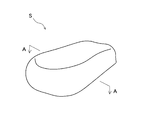
- 1 is a perspective view of a vehicle seat according to an embodiment of the present invention.
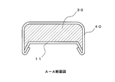
- FIG. 3 is a cross-sectional view taken along line AA of FIG. 2 according to an embodiment of the present invention.
- It is a wavelength absorption / transmission characteristic figure of the infrared absorption pigment which concerns on one Embodiment of this invention.
- It is a cross-sectional schematic diagram of the skin material which concerns on one Embodiment of this invention.
- Measurement result of heat flow rate according to one embodiment of the present invention It is a schematic diagram of the structural unit of the embossed pattern which concerns on one Embodiment of this invention. It is a sensory evaluation test result concerning one embodiment of the present invention.
- FIG. 1 is a side view of a motorcycle equipped with a vehicle seat
- FIG. 2 is a perspective view of the vehicle seat
- FIG. 4 is a wavelength absorption / transmission characteristic of an infrared absorbing pigment
- FIG. 5 is a schematic sectional view of a skin material
- FIG. 6 is a measurement result of heat flow rate
- FIG. 8 shows the sensory evaluation test results.
- the vehicle seat S of the present embodiment is a seating seat used for, for example, a motorcycle as shown in FIGS.
- the vehicle seat S of the present embodiment can be used not only for scooter type motorcycles as shown, but also for large motorcycles. Besides motorcycles, buggies, water bikes, It can be applied as a seat for snowmobiles and open cars.
- the skin 1 used for the vehicle seat S can also be used as an interior material such as a covering material for a handle of an automobile or a motorcycle or a dashboard of an automobile.
- the vehicle seat S includes at least a bottom plate 11, a cushion material 30, and a skin material 40.
- the vehicle seat S is configured by covering the cushion material 30 disposed on the bottom plate 11 with the skin material 40 and fixing the end of the skin material 40 to the back side of the bottom plate 11.
- the vehicle seat S is not limited to a single seat as shown in the present embodiment, and may be a seating seat for two people.
- the bottom plate 11 is made of a hard resin in order to obtain a predetermined strength, and is, for example, injection molded with polypropylene.
- a hinge (not shown) is provided on the back surface of the bottom plate 11 as a connecting portion to the vehicle side. By this hinge part, the vehicle seat S is configured to be openable and closable with respect to a storage part (not shown) provided on the vehicle body side.
- the cushion material 30 is made of a flexible foam material made of, for example, urethane foam, PP (polypropylene) foam, or PE (polyethylene) foam. Moreover, it is good also as a structure using the foam formed from the mixture of a fiber cushion or a urethane chip
- the skin material 40 has a skin 1 disposed on the seating surface side of the vehicle seat S, and a base fabric 8 made of knitted fabric attached to the back side thereof with an adhesive.
- a texture pattern M is formed by combining the concave portions 4 and the convex portions 5.
- the skin 1 is a synthetic resin layer composed of a synthetic resin mainly composed of polyvinyl chloride.
- the synthetic resin contains an infrared transmitting pigment.
- Polyvinyl chloride consists of the formulation shown in Table 1, which is a toughening formulation aimed at protecting infrared transmitting pigments.
- the blending amount means a value proportional to the blended weight.
- Polyvinyl chloride may be a foam, and a woolen nylon cloth or the like can be used as the base cloth.
- the polyvinyl chloride and the polyvinyl chloride foam are transparent or white, and both have high infrared transmittance.
- the black infrared transmitting pigment is mixed with three primary infrared transmitting pigments to make it black.
- three types of pigments CROMOPHTAL Yellow 2RLTS (yellow pigment), CROMOPHTAL Blue 4GNP (blue pigment), IRGAZIN DPP Rubine TR (red pigment), mixed with Ciba Specialty Chemicals, Inc., are used to transmit black infrared rays. Consists of pigments.
- the blending amount of the infrared transmitting pigment with respect to the polyvinyl chloride 100 is set to 1.
- CROMOPHTAL Yellow 2RLTS which is a yellow pigment
- CROMOPHTAL Blue 4GNP a blue pigment
- IRGAZIN DPP Rubin TR is a powder pigment mainly composed of a diketoropyrrolopyrrole pigment.
- the compounding quantity of the infrared transmission pigment with respect to the polyvinyl chloride 100 is 1, the compounding quantity can be arbitrarily adjusted within the range of 0.3-10. If the blending amount of the infrared transmitting pigment is less than 0.3, it becomes difficult to color black, so it is necessary to set it to 0.3 or more. On the other hand, if the blending amount exceeds 10, the properties of the polyvinyl chloride change, causing problems in the manufacturing process, so the blending amount is set to 10 or less. In addition, an infrared transmitting pigment having an arbitrary color can be produced by adjusting the blending amounts of the three primary color infrared transmitting pigments.
- FIG. 4 shows the wavelength absorption / transmission characteristics of the infrared transmitting pigment used in this embodiment.
- FIG. 4 also shows the wavelength absorption / transmission characteristics of carbon black and perylene pigment.
- the wavelength ⁇ belonging to the range of about 700 nm to 10,000 nm is infrared.
- any pigment composed of an infrared transmitting pigment constituting the infrared transmitting pigment has excellent infrared transmission characteristics regardless of the blending ratio.
- FIG. 6 shows the relationship between the elapsed time from the contact and the heat flow rate, the skin 1 in which the infrared transmitting pigment is dispersed (infrared transmitting pigment dispersed skin) and the conventional skin in which carbon black is dispersed (carbon black dispersed skin). It is the result of measurement.
- a contact temperature detection sensor described later was used for the measurement of the heat flow rate.
- an epidermis in which the texture pattern M was not formed was used.
- the contact temperature detection sensor After irradiating the skin with dispersed infrared permeable pigment (infrared transmissive pigment dispersed skin) and the skin with carbon black dispersed (carbon black dispersed skin) for each specified time, the contact temperature detection sensor is brought into contact to determine the heat flow rate. It was measured.
- both the infrared transmitting pigment dispersed skin and the carbon black dispersed skin are 0.1 to 0.2 seconds after the contact temperature detection sensor contacts the non-measured skin.
- the heat flow rate Q shows the maximum value (Q-MAX value).
- the infrared transmission pigment dispersion skin is 0.46 [J / cm 2 ⁇ s]
- the carbon black dispersion skin is 1.38 [J / cm 2 ⁇ s].
- the infrared-transmitting pigment-dispersed skin has a Q-MAX value that is reduced to about 3 compared to the conventional skin. That is, by dispersing the infrared transmitting pigment in the skin 1, the heat flow rate can be greatly reduced, and the heat felt by the occupant when the skin 1 is touched can be greatly reduced.
- the wrinkle pattern M expresses a texture by attaching irregularities to the surface of the epidermis 1, and includes a concave portion 4 and a convex portion 5.
- the weight of the passenger seated on the seat S is supported by the convex portion 5 of the texture pattern M. Therefore, the occupant feels the heat of the sheet S mainly by the heat transmitted from the convex portion 5.
- the height difference between the concave portion 4 and the convex portion 5 of the texture pattern M is sufficiently large, the occupant does not come into contact with the concave portion 4, so that the heat inflow from the concave portion 4 is reduced.
- the heat that flows from the convex portion 5 to the passenger side is diffused to a position facing the concave portion 4. That is, the heat perceived by the occupant varies depending on the shapes of the concave portion 4 and the convex portion 5 that form the texture pattern M.
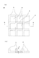
- FIG. 7 is a schematic diagram of the structural unit of the texture pattern
- FIG. 8 shows the sensory evaluation test results.
- 7A is a front view of a texture pattern
- FIG. 7B is a cross-sectional view taken along line BB in FIG. 7A.
- the texture pattern M (M1, M2, M3, M4) formed on the surface of the test skin will be described.
- the texture pattern M (M1, M2, M3, M4) is configured by arranging the constituent units composed of the convex portions 5 and the concave portions 4 in the vertical and horizontal directions. ing.
- the structural unit has a size of 3 mm ⁇ 3 mm, and includes a substantially square-shaped recess 4 and a protrusion 5 formed continuously on the left and upper sides of the recess 4.
- the area ratio R of the convex portion 5 is changed to form four kinds of embossed patterns M1, M2, M3, and M4.
- Three types (100, 200, and 300 ⁇ m) of different types of wrinkle patterns M1, M2, M3, and M4 having different height differences (texture depths) h between the convex portions 5 and the concave portions 4 were produced.
- the embossed pattern M1 is formed with the concave portion 4 being 2.75 mm 2 (approximately 1.66 mm ⁇ 1.66 mm) with respect to the area of the convex portion being 6.25 mm 2 .
- the area of the convex portion 5 in the texture pattern 1M is approximately 70%.
- Grain pattern M2, the area of the projections with respect to 5.94 mm 2, is formed a recess 4 as 3.06 mm 2 (approximately 1.75 mm ⁇ 1.75 mm).
- the area of the convex part 5 in the embossed pattern M2 is approximately 66%.
- the embossed pattern M3 is formed such that the concave portion 4 is 5.94 mm 2 (approximately 2.44 mm ⁇ 2.44 mm) while the area of the convex portion is 3.06 mm 2 .
- the area of the convex part 5 in the embossed pattern M3 is approximately 34%.
- Grain pattern M4 the area of the projections with respect to 2.75 mm 2, is formed a recess 4 as 6.25mm 2 (2.5mm ⁇ 2.5mm).
- the area of the convex portion 5 in the texture pattern M4 is approximately 31%.
- a pattern in which the height difference h between the convex portion 5 and the concave portion 4 is adjusted to 100, 200, and 300 ⁇ m is prepared.
- the epidermis was subjected to a sensory evaluation test.
- a contact temperature detection sensor (Finger Robot Thermolab KES-F7 manufactured by Kato Tech Co., Ltd.) used in the sensory evaluation test will be described.
- This contact temperature detection sensor can detect the maximum value (Q-MAX value) of the heat flow rate after the contact sensor portion (measurement surface) is brought into contact with the skin 1 (measurement object). By making the temperature difference between the measurement object and the measurement surface constant, quantitative measurement can be performed.
- the measurement object the surface of the epidermis 1 was irradiated with a light beam equivalent to sunlight, while the contact sensor portion was measured as the surface temperature of the skin.
- the measurement surface of the contact temperature detection sensor is a substantially circular shape with a diameter of about 10 mm covered with silicon rubber, and includes a temperature sensor.
- the maximum value (Q-MAX value) of the heat flow rate can be calculated from the temperature history when the measurement surface is pressed against the non-measurement object (texture pattern M).
- the Q-MAX value measured by this contact temperature detection sensor when it is 0.90 or more, it feels “heat that cannot be tolerated”, and if it is 0.65 to 0.90, the passenger can tolerate it. The passenger feels “hot”, and if it is 0.50 to 0.65, the passenger perceives it as “warm”. According to the sensory evaluation test results shown in FIG. 8, the Q-MAX value was less than 0.90 in all the test skins even though the temperature of the skin 1 was 70 ° C., and the texture pattern M was formed. The effect is appearing. Furthermore, with the embossed pattern M3 and the embossed pattern M4, a Q-MAX value of less than 0.65 was recorded in the test skin having a texture depth of 300 ⁇ m.
- the maximum value of the heat flow rate flowing from the skin (Q-MAX value) is considered to be smaller as the ratio of the convex part 5 is smaller or the grain depth is deeper. It is done.
- Q-MAX value the maximum value of the heat flow rate flowing from the skin
- the sensible temperature of the passenger is “warm” level. Can be suppressed.
- the embossing depth can be further increased according to the thickness of the skin 1, but it is desirable to set the value to 3 mm (3000 ⁇ m) or less in consideration of workability in the manufacturing process.
- the heat perceived by the occupant is effectively reduced by synthesizing the effect of suppressing the increase in the surface temperature of the skin 1 and the effect of reducing the sensory temperature by the texture pattern M by blending the infrared transmitting pigment into the skin 1.
- the texture pattern M is formed in the shape shown in FIG. 7, but the same effect can be obtained regardless of the shape of the pattern as long as it is a pattern composed of the convex portion 5 and the concave portion 4 such as leather texture. Have.
- the same effect can be obtained by forming the texture pattern M not only from the two-layer pattern of the convex portion 5 and the concave portion 4 but also from a pattern composed of multiple stages or a rounded pattern.
- the surface does not become hot even when left under the hot sun.
- the use of an infrared transmitting pigment is advantageous in terms of a temperature rise reduction effect as compared with the case of using an infrared reflecting pigment.
- the infrared reflective pigment has an effect of lowering the surface temperature by about 10 to 15 ° C. compared to the general pigment (carbon black), whereas the infrared transmission pigment reduces the surface temperature by 15 to 20 ° C. , Have a greater reduction effect.
- the infrared transmitting pigment can easily increase the absorption of visible light more than the infrared reflecting pigment, and can improve jetness.
Landscapes
- Engineering & Computer Science (AREA)
- Mechanical Engineering (AREA)
- Aviation & Aerospace Engineering (AREA)
- Transportation (AREA)
- Laminated Bodies (AREA)
- Mattresses And Other Support Structures For Chairs And Beds (AREA)
Abstract
【課題】炎天下に放置してもシートが熱くなりにくい車両用シートを提供する。 【解決手段】車両用シートSは、表面にシボ模様Mを有するとともに、ボトムプレート上に配置されるクッション材30を被覆する表皮材40を備えており、表皮材40は、赤外線透過顔料が分散された合成樹脂からなる表皮1を有し、表皮1の表面に形成されたシボ模様Mは、凸部5と凹部4とを有して構成され、凸部5と凹部4との高低差を有し、且つ、表皮1の表面に対して凸部は所定以下の割合とされている。このように、表皮1を構成することにより、車両用シートSを炎天下に露出して放置した場合であっても、赤外線は表皮1を透過するとともに乗員は凸部5でのみ表皮1と接触するため車両用シートS表面を熱く感じない。
Description
本発明は、車両用シートに係り、特に、自動二輪車や水上バイクなどの炎天下に曝された状態で使用される車両用シートに関する。
従来、例えば自動二輪車用のシートは、デザイン上黒色のものが好まれており、合成樹脂、例えばポリ塩化ビニルよりなる表皮と、その表皮に分散された黒色顔料としてのカーボンブラックとから構成される。
このようなカーボンブラックを顔料として用いた表皮は、安価であり且つ化学的にも安定であるという利点を有しているが、炎天下に曝された状態で自動二輪車を放置した場合、カーボンブラックの赤外線吸収効果により表皮が熱くなるという不都合があった。
そこで、表皮材に赤外線反射顔料を配合して、照射された赤外線を反射することで蓄熱や温度上昇を防ぐことができる車両用シートが提案されている(特許文献1)。
また、赤外線の波長領域の電磁波を反射させることで、日光の照射による内部温度の上昇を抑えることができる着色シートが提案されている(特許文献2)。
また、赤外線の波長領域の電磁波を反射させることで、日光の照射による内部温度の上昇を抑えることができる着色シートが提案されている(特許文献2)。
特許文献1に記載の車両用シートでは、炎天下に放置された車両用シートの温度上昇を抑える効果があるが、さらに高い効果を有する車両用シートが望まれている。
また、特許文献2に記載の着色シートは、車両用シートの表皮材としても用いることができるものの、車両用シートの加熱を抑える効果としては不十分なものであり、さらに高い効果を有する表皮材が望まれている。
また、特許文献2に記載の着色シートは、車両用シートの表皮材としても用いることができるものの、車両用シートの加熱を抑える効果としては不十分なものであり、さらに高い効果を有する表皮材が望まれている。
本発明の目的は、炎天下に曝されてもシートの着座面が熱くなりにくい車両用シートを提供することにある。
前記課題は、請求項1の車両用シートによれば、ボトムプレート上に配置されるクッション材と、表面にシボ模様を備え、前記クッション材を被覆する表皮材と、を有して構成される車両用シートであって、前記表皮材は、赤外線透過顔料が分散された表皮を有してなり、前記表皮の表面に形成された前記シボ模様は、凸部と凹部とを有して構成されることにより解決される。
このように、表皮材は、赤外線透過顔料が分散された表皮を有してなり、表皮の表面に形成されたシボ模様は、凸部と凹部とを有して構成されることによって、車両用シートの表皮に照射された赤外線は、表皮を透過してクッション材中に拡散されるため、照射された赤外線によって表皮が加熱されることが抑制される。また、表皮のシボ模様を凸部と凹部とを有して構成し、乗員が凸部にのみ触れるように構成することで、表皮から伝わる熱流速を減少させ、乗員が熱いと感じづらくしている。従って、炎天下に曝されても着座面が熱いと感じにくい車両用シートが得られる。さらに、赤外線透過顔料を用いることによって、赤外線反射顔料を用いた場合よりも、着座面の昇温削減効果と漆黒性を向上させた車両用シートが得られる。
前記課題は、請求項2の車両用シートによれば、ボトムプレート上に配置されるクッション材と、表面にシボ模様を備え、前記クッション材を被覆する表皮材と、を有して構成される車両用シートであって、前記表皮材は、赤外線透過顔料が分散された表皮を有してなり、前記表皮の表面に形成された前記シボ模様は、凸部と凹部とを有して構成され、前記凸部と前記凹部との高低差は300μm以上、3000μm以下であり、且つ、前記表皮の表面に対する凸部の表面積の割合は10%以上、34%以下であることにより解決される。
このように、表皮材は、赤外線透過顔料が分散された表皮を有してなることによって、車両用シートの表皮に照射された赤外線は、表皮を透過してクッション材中に拡散され、照射された赤外線によって表皮が加熱されることが抑制される。また、凸部と凹部との高低差は300μm以上且つ表皮の表面に対する凸部の表面積の割合を34%以下にすることで、乗員が直接触れる面積を減らして表皮から伝わる熱流速を減少させ、乗員が熱いと感じづらくしている。従って、炎天下に曝されても着座面が熱いと感じにくい車両用シートが得られる。
具体的には、請求項3のように、前記表皮は、合成樹脂と前記合成樹脂中に分散された赤外線透過顔料とを有して構成され、前記合成樹脂は、ポリ塩化ビニル若しくは発泡ポリ塩化ビニルの一方よりなると好適である。
上記構成によって、赤外線透過性の樹脂を安定して分散させることができ、表皮材及びこの表皮材を用いた車両用シートの製造に従来の製造方法をそのまま活用することができる。
上記構成によって、赤外線透過性の樹脂を安定して分散させることができ、表皮材及びこの表皮材を用いた車両用シートの製造に従来の製造方法をそのまま活用することができる。
さらに具体的には、請求項4のように、前記表皮を構成する合成樹脂の配合量を100としたとき、前記赤外線透過顔料の配合量が0.3以上10以下であると好適である。
このように、表皮を構成する合成樹脂の配合量を100としたとき、赤外線透過顔料の配合量が0.3以上10以下とすることで、表皮に照射された赤外線を透過させることができる。赤外線透過顔料の配合量が0.3未満では所定の色彩に着色することができず、配合量が10を超えると合成樹脂の性質が大きく変化して製造工程での不具合が生じることから、配合量は0.3以上10以下に設定される。
このように、表皮を構成する合成樹脂の配合量を100としたとき、赤外線透過顔料の配合量が0.3以上10以下とすることで、表皮に照射された赤外線を透過させることができる。赤外線透過顔料の配合量が0.3未満では所定の色彩に着色することができず、配合量が10を超えると合成樹脂の性質が大きく変化して製造工程での不具合が生じることから、配合量は0.3以上10以下に設定される。
また、請求項5のように、前記赤外線透過顔料は、イソインドリン系顔料、ベータ型銅フタロシアニン系顔料、ジケトロピロロピロール系顔料、のいずれか1つ以上からなると好適である。
このように、赤外線透過顔料は、イソインドリン系化合物、ベータ型銅フタロシアニン系化合物、ジケトロピロロピロール系化合物、のいずれか1つ以上からなることで、優れた赤外線透過特性を有する顔料を得ることができ、このような顔料を用いて着色することにより、炎天下に曝されても着座面が熱いと感じにくい車両用シートが得られる。
このように、赤外線透過顔料は、イソインドリン系化合物、ベータ型銅フタロシアニン系化合物、ジケトロピロロピロール系化合物、のいずれか1つ以上からなることで、優れた赤外線透過特性を有する顔料を得ることができ、このような顔料を用いて着色することにより、炎天下に曝されても着座面が熱いと感じにくい車両用シートが得られる。
本発明によれば、車両用シートの表皮に照射された赤外線を透過してクッション材中に拡散させることで、表皮が熱くなることを防ぎ、また、表皮の表面に対する凸部の割合を所定値以下にして乗員が直接触れる面積を減らすことで、表皮から伝わる熱流速を減少させ、乗員が熱いと感じづらくしている。従って、炎天下に曝されても着座面が熱いと感じにくい車両用シートを提供することができる。
S 車両用シート
M,M1,M2,M3,M4 シボ模様
h シボ深さ(凸部と凹部との高低差)
1 表皮
4 凹部
5 凸部
8 基布
11 ボトムプレート
30 クッション材
40 表皮材
M,M1,M2,M3,M4 シボ模様
h シボ深さ(凸部と凹部との高低差)
1 表皮
4 凹部
5 凸部
8 基布
11 ボトムプレート
30 クッション材
40 表皮材
以下、本発明の一実施形態について図面に基づいて説明する。なお、以下に説明する部材、配置等は本発明を限定するものでなく、本発明の趣旨の範囲内で各種改変することができることは勿論である。
図1乃至図8は、本発明の一実施形態に係るものであり、図1は車両用シートを備えた自動二輪車の側面図、図2は車両用シートの斜視図、図3は図2のA-A断面図、図4は赤外線吸収顔料の波長吸収/透過特性、図5は表皮材の断面模式図、図6は熱流速の測定結果、図7はシボ模様の構成単位の模式図である。また、図8は官能評価試験結果である。
本実施形態の車両用シートSは、図1と図2に示すように、例えば、自動二輪車に使用される着座シートである。なお、本実施形態の車両用シートSは、図示されているようなスクータ型のオートバイだけではなく、大型の自動二輪車にも使用可能であり、また、オートバイの他にも、バギー、水上バイク、スノーモービル、オープンカーなどのシートとして適用可能である。なお、車両用シートSに用いられる表皮1を、自動車や自動二輪車のハンドルの被覆材や自動車のダッシュボードなどの内装材として利用することもできる。
図3に示すように、車両用シートSは、ボトムプレート11と、クッション材30と、表皮材40とを少なくとも備えている。表皮材40でボトムプレート11上に配置されたクッション材30を被覆し、表皮材40の端部をボトムプレート11の裏側に止着することによって車両用シートSが構成されている。なお、車両用シートSは、本実施形態に示すような一人乗りに限られず、二人乗り用の着座シートであってもよい。
ボトムプレート11は、所定の強度を得るため硬質樹脂から形成されており、例えば、ポリプロピレンで射出成形されている。ボトムプレート11の裏面には、車両側への連結部としてヒンジ(図示せず)が設けられている。このヒンジ部によって車両用シートSが車体側に設けられた収納部(図示せず)に対して開閉可能に構成されている。
クッション材30は、例えば、ウレタンフォーム、PP(ポリプロピレン)フォーム、PE(ポリエチレン)フォームからなる柔軟フォーム材から構成されている。また、繊維クッションや、ウレタンチップと熱硬化性バインダの混合物より形成された発泡体を用いる構成としてもよい。
表皮材40は、車両用シートSの着座面側に配置される表皮1と、その背面側に接着剤を介してメリヤスよりなる基布8が貼付されている。
表皮1の表面(着座面側の表面)は、凹部4と凸部5とを組み合わせたシボ模様Mが形成されている。
表皮1は、ポリ塩化ビニルを主要成分とする合成樹脂から構成された合成樹脂層である。また、合成樹脂には赤外線透過顔料が配合されている。
表皮1の表面(着座面側の表面)は、凹部4と凸部5とを組み合わせたシボ模様Mが形成されている。
表皮1は、ポリ塩化ビニルを主要成分とする合成樹脂から構成された合成樹脂層である。また、合成樹脂には赤外線透過顔料が配合されている。
ポリ塩化ビニルは表1に示した配合物よりなり、これは、赤外線透過顔料の保護を目的とした強化配合物である。なお、配合量は、配合した重量に比例した値を意味する。ポリ塩化ビニルは発泡体でもよく、また基布としてはウーリーナイロン布などを用いることができる。なお、ポリ塩化ビニル及びポリ塩化ビニル発泡体は透明若しくは白色であり、いずれも赤外線の透過率は高い値を有している。
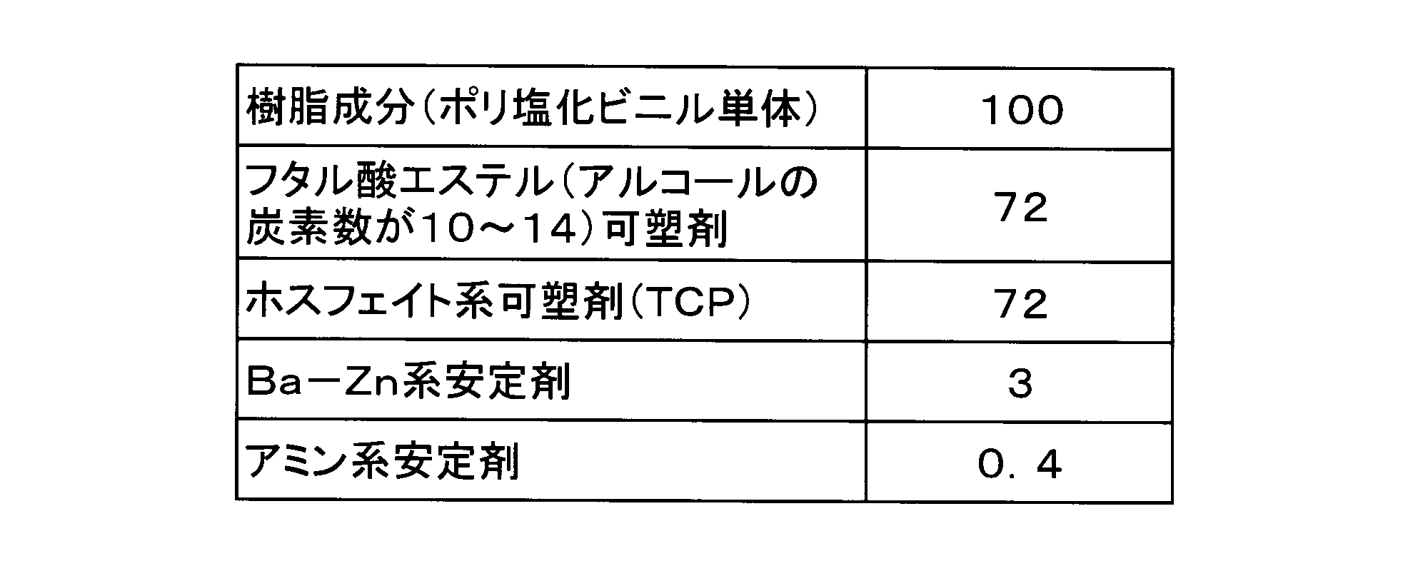
黒色の赤外線透過顔料は、三原色の赤外線透過顔料を混合して黒色としている。具体的には、チバ・スペシャルティ・ケミカルズ社製、CROMOPHTAL Yellow 2RLTS(黄色顔料),CROMOPHTAL Blue 4GNP(青色顔料),IRGAZIN DPP Rubine TR(赤色顔料)の3種類の顔料を混合して黒色の赤外線透過顔料を構成している。本実施形態においては、ポリ塩化ビニル100に対する赤外線透過顔料の配合量は、1に設定されている。
ここで、黒色の赤外線透過顔料を構成する三原色の赤外線透過顔料について説明する。
黄色顔料であるCROMOPHTAL Yellow 2RLTSは、イソインドリノン系顔料を主成分とする粉末顔料であり、青色顔料のCROMOPHTAL Blue 4GNPは、ベータ型銅フタロシアニン系顔料を主成分とする粉末顔料であり、赤色顔料のIRGAZIN DPP Rubine TRは、ジケトロピロロピロール系顔料を主成分とする粉末顔料である。これらの化合物はいずれも多環式系顔料に属し、優れた赤外線透過特性を有している。
黄色顔料であるCROMOPHTAL Yellow 2RLTSは、イソインドリノン系顔料を主成分とする粉末顔料であり、青色顔料のCROMOPHTAL Blue 4GNPは、ベータ型銅フタロシアニン系顔料を主成分とする粉末顔料であり、赤色顔料のIRGAZIN DPP Rubine TRは、ジケトロピロロピロール系顔料を主成分とする粉末顔料である。これらの化合物はいずれも多環式系顔料に属し、優れた赤外線透過特性を有している。
なお、本実施形態においては、ポリ塩化ビニル100に対する赤外線透過顔料の配合量を1としているが、配合量は0.3以上10以下の範囲内で任意に調整することができる。赤外線透過顔料の配合量が0.3未満では黒色に着色することが困難となることから0.3以上とする必要がある。一方、配合量が10を超えるとポリ塩化ビニルの性質が変化するため製造工程で不具合が生じる原因となることから配合量は10以下に設定される。また、三原色の赤外線透過顔料の配合量を調整することで任意の色を有する赤外線透過顔料を作製することができる。
図4に本実施形態で使用した赤外線透過顔料の波長吸収/透過特性を示す。比較のため、図4中にはカーボンブラック、及びペリレン系顔料の波長吸収/透過特性を併記した。
図4より、従来顔料として使用されてきたカーボンブラックは、透過率Tが測定された全波長領域で10%程度以下の透過率Tを示したのに対して、赤外線透過顔料は、およそ波長λ=680nm以上の波長領域での透過率Tが90%以上の値を示している。ここで、およそ700nmから10000nmの範囲に属する波長λが赤外線である。
図4より、従来顔料として使用されてきたカーボンブラックは、透過率Tが測定された全波長領域で10%程度以下の透過率Tを示したのに対して、赤外線透過顔料は、およそ波長λ=680nm以上の波長領域での透過率Tが90%以上の値を示している。ここで、およそ700nmから10000nmの範囲に属する波長λが赤外線である。
また、多環式系顔料として従来から用いられているペリレン系顔料は、波長λ=750nm以上の波長領域で良好な透過率を示すものの、波長680~750nmの間の赤外線透過率は低い値を示している。そのため、赤外線透過顔料は赤外線領域の波長λの大部分を透過させることができる。もちろん、赤外線透過顔料を構成する赤外線透過顔料からなる顔料であれば配合比に関わらず優れた赤外線透過特性を有する。
また、赤外線透過顔料が分散された合成樹脂は赤外線透過率が高いため、表皮1に照射された赤外線は、表皮1を透過し、メリヤスよりなる基布8の間を通過してクッション材30に吸収される。従って、シートSの表面に照射された赤外線は表皮1を透過するため、シートSの表面を加熱することがなく、炎天下に放置された車両のシートSの表面が熱くなることを抑えることができる。一方、可視光線(波長λ=350~700nm)の大部分は透過させないためシートSには任意の色に着色することができる。この様子を図5に模式的に示した。なお、本実施形態においては上述した黒色の赤外線透過顔料を用いた。
赤外線透過顔料が分散された表皮1の効果を確認するため、表皮1から伝達される熱量変化を測定した。図6は、接触時からの経過時間と熱流速の関係について、赤外線透過顔料が分散された表皮1(赤外線透過顔料分散表皮)とカーボンブラックを分散させた従来の表皮(カーボンブラック分散表皮)を測定した結果である。熱流速の測定には後述する接触温度検出センサーを使用した。また、測定にはシボ模様Mが形成されていない状態の表皮を使用した。赤外線透過顔料を分散させた表皮(赤外線透過顔料分散表皮),カーボンブラックを分散させた表皮(カーボンブラック分散表皮)にそれぞれ赤外線を所定時間照射した後に、接触温度検出センサーを接触させて熱流速を測定した。
図6の熱流速の測定結果によれば、赤外線透過顔料分散表皮,カーボンブラック分散表皮のいずれも、接触温度検出センサーが非測定物である表皮に接触してから0.1~0.2秒後に熱流速Qが最大値(Q-MAX値)を示している。Q-MAX値で比較すると、赤外線透過顔料分散表皮は、0.46[J/cm2・s]であるのに対し、カーボンブラック分散表皮は、1.38[J/cm2・s]であり、赤外線透過顔料分散表皮はQ-MAX値が従来の表皮と比べておよそ1/3にまで低下している。すなわち、表皮1に赤外線透過顔料を分散させることにより熱流速を大幅に低下させることができ、表皮1に触れた際に乗員が感じる熱さを大幅に軽減できる。
次に、表皮1の表面に施されたシボ模様Mについて説明する。
シボ模様Mは、表皮1の表面に凹凸を付すことにより質感を表現したものであり、凹部4と凸部5とから構成されている。シボ模様Mの凸部5によって、シートSに着座した乗員の体重が支えられることになる。従って、乗員は、主に凸部5から伝わる熱によってシートSの熱さを感じる。一方、シボ模様Mの凹部4と凸部5の高低差が十分に大きいときには乗員は凹部4に接触しないため、凹部4からの熱の流入は少なくなる。そのため、凸部5から乗員側に流入した熱は凹部4に対向する位置に拡散されることになる。すなわち、シボ模様Mを構成する凹部4と凸部5の形状によって、乗員が知覚する熱さに差異が生じることになる。
シボ模様Mは、表皮1の表面に凹凸を付すことにより質感を表現したものであり、凹部4と凸部5とから構成されている。シボ模様Mの凸部5によって、シートSに着座した乗員の体重が支えられることになる。従って、乗員は、主に凸部5から伝わる熱によってシートSの熱さを感じる。一方、シボ模様Mの凹部4と凸部5の高低差が十分に大きいときには乗員は凹部4に接触しないため、凹部4からの熱の流入は少なくなる。そのため、凸部5から乗員側に流入した熱は凹部4に対向する位置に拡散されることになる。すなわち、シボ模様Mを構成する凹部4と凸部5の形状によって、乗員が知覚する熱さに差異が生じることになる。
ここで、4種類のシボ模様M(M1,M2,M3,M4)を有する表皮1を試作して、それぞれについて乗員が知覚する熱さを擬似的に測定した官能評価試験を行った。シボ模様Mを形成した表皮1は、上述した赤外線透過顔料を分散させたものである。
図7にシボ模様の構成単位の模式図、図8に官能評価試験結果を示す。なお、図7(a)はシボ模様の正面図、図7(b)は図7(a)のB-B断面図である。
図7にシボ模様の構成単位の模式図、図8に官能評価試験結果を示す。なお、図7(a)はシボ模様の正面図、図7(b)は図7(a)のB-B断面図である。
試験表皮の表面に形成したシボ模様M(M1,M2,M3,M4)について説明する。図7(a),(b)に示すように、シボ模様M(M1,M2,M3,M4)はいずれも、凸部5と凹部4とからなる構成単位を縦横方向に配列させて構成されている。構成単位は、3mm×3mmの大きさを有しており、略正方形状の凹部4と、凹部4の左側と上側に連続して形成された凸部5と、から構成されている。この構成単位において、凸部5と凹部4のサイズの比率を変更することによって、凸部5の面積比率Rを変更して4種類のシボ模様M1,M2,M3,M4を形成するとともに、4種類のシボ模様M1,M2,M3,M4のそれぞれについて、凸部5と凹部4との高低差(シボ深さ)hの異なるものを3種類(100,200,300μm)ずつ作製した。
シボ模様M1,M2,M3,M4のそれぞれについて具体的に説明する。
シボ模様M1は、凸部の面積が6.25mm2に対して、凹部4を2.75mm2(およそ1.66mm×1.66mm)として形成されている。シボ模様1M中の凸部5の面積はおよそ70%である。
シボ模様M2は、凸部の面積が5.94mm2に対して、凹部4を3.06mm2(およそ1.75mm×1.75mm)として形成されている。シボ模様M2中の凸部5の面積はおよそ66%である。
シボ模様M1は、凸部の面積が6.25mm2に対して、凹部4を2.75mm2(およそ1.66mm×1.66mm)として形成されている。シボ模様1M中の凸部5の面積はおよそ70%である。
シボ模様M2は、凸部の面積が5.94mm2に対して、凹部4を3.06mm2(およそ1.75mm×1.75mm)として形成されている。シボ模様M2中の凸部5の面積はおよそ66%である。
シボ模様M3は、凸部の面積が3.06mm2に対して、凹部4を5.94mm2(およそ2.44mm×2.44mm)として形成されている。シボ模様M3中の凸部5の面積はおよそ34%である。
シボ模様M4は、凸部の面積が2.75mm2に対して、凹部4を6.25mm2(2.5mm×2.5mm)として形成されている。シボ模様M4中の凸部5の面積はおよそ31%である。
このようなシボ模様M1,M2,M3,M4のそれぞれについて、凸部5と凹部4との高低差hを、100,200,300μmに調整したものを作製し、この計12種類のシボ模様を有する表皮について官能評価試験に供した。
シボ模様M4は、凸部の面積が2.75mm2に対して、凹部4を6.25mm2(2.5mm×2.5mm)として形成されている。シボ模様M4中の凸部5の面積はおよそ31%である。
このようなシボ模様M1,M2,M3,M4のそれぞれについて、凸部5と凹部4との高低差hを、100,200,300μmに調整したものを作製し、この計12種類のシボ模様を有する表皮について官能評価試験に供した。
官能評価試験に用いた接触温度検出センサー(カトーテック社製 フィンガーロボットサーモラボKES-F7)について説明する。
この接触温度検出センサーは、接触センサー部分(測定面)を表皮1(被測定物)に接触させた後の熱流速の最大値(Q-MAX値)を検出することができるものであり、被測定物と測定面との温度差を一定とすることで、定量的な測定を行うことができる。本実施形態においては、被測定物(表皮1の表面)は太陽光と同等な光線を照射した状態とし、一方、接触センサー部分を皮膚の表面温度として測定を行った。
この接触温度検出センサーは、接触センサー部分(測定面)を表皮1(被測定物)に接触させた後の熱流速の最大値(Q-MAX値)を検出することができるものであり、被測定物と測定面との温度差を一定とすることで、定量的な測定を行うことができる。本実施形態においては、被測定物(表皮1の表面)は太陽光と同等な光線を照射した状態とし、一方、接触センサー部分を皮膚の表面温度として測定を行った。
人体は皮膚表面近傍の神経に流入する熱流量で熱さを知覚するため、このような測定により乗員が知覚する熱さに近似したデータを得ることができる。
なお、接触温度検出センサーの測定面はシリコンゴムで被覆された直径10mm程度の略円形であり、温度センサーを備えている。測定面を非測定物(シボ模様M)に押しつけた際の温度履歴から熱流速の最大値(Q-MAX値)を算出することができる。
なお、接触温度検出センサーの測定面はシリコンゴムで被覆された直径10mm程度の略円形であり、温度センサーを備えている。測定面を非測定物(シボ模様M)に押しつけた際の温度履歴から熱流速の最大値(Q-MAX値)を算出することができる。
この接触温度検出センサーにおいて測定されるQ-MAX値によれば、0.90以上では「我慢できない程の熱さ」を感じ、0.65~0.90であれば乗員は我慢できる程度ではあるが「熱い」と感じ、また、0.50~0.65であれば「暖かい」と乗員が知覚する。
図8に示した官能評価試験結果によると、表皮1の温度を70℃にしたにも関わらず全ての試験表皮においてQ-MAX値は0.90を下回っており、シボ模様Mが形成された効果が現れている。
さらに、シボ模様M3とシボ模様M4で、シボ深さ300μmの試験表皮においては、0.65を下回るQ-MAX値が記録された。
図8に示した官能評価試験結果によると、表皮1の温度を70℃にしたにも関わらず全ての試験表皮においてQ-MAX値は0.90を下回っており、シボ模様Mが形成された効果が現れている。
さらに、シボ模様M3とシボ模様M4で、シボ深さ300μmの試験表皮においては、0.65を下回るQ-MAX値が記録された。
熱は接触している部分から多く伝わるため、表皮から流入する熱流速の最大値(Q-MAX値)は、凸部5の割合が小さいほど、または、シボ深さが深いほど、小さくなると考えられる。図8に示した官能評価試験結果では、シボ模様M3のシボ深さ300μmの表皮1で0.65を下回るQ-MAX値が測定されたことから、少なくとも、シボ深さ300μm以上、且つ、表皮1の表面に対する凸部5の割合が34%以下の表皮1では、同様の結果を示すと考えられる。
すなわち、シボ深さ300μm以上で表皮1の表面に対する凸部5の割合が34%以下の表皮1では、炎天下でシートSの表面温度が上昇した場合にも、乗員の体感温度を「暖かい」レベルに抑えることができる。
なお、シボ深さは表皮1の厚さに応じて更に深く形成することができるが、製造工程での作業性などを考慮すると3mm(3000μm)以下の値とすることが望ましい。また、凸部5の割合は、小さいほど熱流速の最大値は低下するが、小さすぎると乗員の体重を支えることが困難になるため、10%程度以上の値とすることが望ましい。
なお、シボ深さは表皮1の厚さに応じて更に深く形成することができるが、製造工程での作業性などを考慮すると3mm(3000μm)以下の値とすることが望ましい。また、凸部5の割合は、小さいほど熱流速の最大値は低下するが、小さすぎると乗員の体重を支えることが困難になるため、10%程度以上の値とすることが望ましい。
図8の官能評価試験結果においては、表皮1の表面温度を70℃と一定としたため、赤外線透過顔料の効果は発揮されづらい測定条件である。そのため、実際に本実施形態に係るシートSを炎天下に放置した場合には、図8に示した試験結果よりも高い効果が現れるものと考えられる。具体的には、赤外線透過顔料を顔料として表皮1に配合することにより、シートSの表面温度を上昇させる赤外線の多くをシートSの内部側に透過させることができるため、表皮1の表面温度の上昇を抑えることができる。
従って、赤外線透過顔料の表皮1への配合によって、表皮1の表面温度の上昇を抑える効果と、シボ模様Mによる体感温度の低減効果との相乗効果によって乗員の知覚する熱さを効果的に低下させることができる。
また、本実施形態においては、シボ模様Mを図7に示した形状として形成したが、皮シボなど、凸部5と凹部4とからなる模様であれば模様の形状に関わらず同様の効果を有する。もちろん、凸部5と凹部4の二階層パターンのみならず、多段階層からなる模様や丸みを帯びた模様からシボ模様Mを構成しても同様の効果を得ることができる。
以上説明したように、本発明の車両用シートSによれば、炎天下に放置されても、表面が熱くならいない。
また、本実施形態においては、シボ模様Mを図7に示した形状として形成したが、皮シボなど、凸部5と凹部4とからなる模様であれば模様の形状に関わらず同様の効果を有する。もちろん、凸部5と凹部4の二階層パターンのみならず、多段階層からなる模様や丸みを帯びた模様からシボ模様Mを構成しても同様の効果を得ることができる。
以上説明したように、本発明の車両用シートSによれば、炎天下に放置されても、表面が熱くならいない。
また、赤外線透過顔料を用いることによって、赤外線反射顔料を用いた場合と比べて、昇温削減効果の点で有利である。具体的には、赤外線反射顔料は、一般顔料(カーボンブラック)に比べて、表面温度を10~15℃ほど下げる効果を有するのに対し、赤外線透過顔料は、表面温度を15~20℃下げるという、より大きな削減効果を有する。
さらに、赤外線透過顔料は、赤外線反射顔料よりも可視光の吸収を高めることが容易であり、漆黒性の向上を図ることができる。
さらに、赤外線透過顔料は、赤外線反射顔料よりも可視光の吸収を高めることが容易であり、漆黒性の向上を図ることができる。
Claims (5)
- ボトムプレート上に配置されるクッション材と、
表面にシボ模様を備え、前記クッション材を被覆する表皮材と、を有して構成される車両用シートであって、
前記表皮材は、赤外線透過顔料が分散された表皮を有してなり、
前記表皮の表面に形成された前記シボ模様は、凸部と凹部とを有して構成されることを特徴とする車両用シート。 - ボトムプレート上に配置されるクッション材と、
表面にシボ模様を備え、前記クッション材を被覆する表皮材と、を有して構成される車両用シートであって、
前記表皮材は、赤外線透過顔料が分散された表皮を有してなり、
前記表皮の表面に形成された前記シボ模様は、凸部と凹部とを有して構成され、前記凸部と前記凹部との高低差は300μm以上、3000μm以下であり、且つ、前記表皮の表面に対する凸部の表面積の割合は10%以上、34%以下であることを特徴とする車両用シート。 - 前記表皮は、合成樹脂と前記合成樹脂中に分散された赤外線透過顔料とを有して構成され、
前記合成樹脂は、ポリ塩化ビニル若しくは発泡ポリ塩化ビニルのいずれか一方よりなることを特徴とする請求項1又は2に記載の車両用シート。 - 前記表皮を構成する合成樹脂の配合量を100としたとき、前記赤外線透過顔料の配合量が0.3以上10以下であることを特徴とする請求項3に記載の車両用シート。
- 前記赤外線透過顔料は、イソインドリン系顔料、ベータ型銅フタロシアニン系顔料、ジケトロピロロピロール系顔料、のいずれか1つ以上からなることを特徴とする請求項1乃至4のいずれか1項に記載の車両用シート。
Applications Claiming Priority (2)
| Application Number | Priority Date | Filing Date | Title |
|---|---|---|---|
| JP2008-312443 | 2008-12-08 | ||
| JP2008312443A JP5215832B2 (ja) | 2008-12-08 | 2008-12-08 | 自動二輪車用シート |
Publications (1)
| Publication Number | Publication Date |
|---|---|
| WO2010067528A1 true WO2010067528A1 (ja) | 2010-06-17 |
Family
ID=42242525
Family Applications (1)
| Application Number | Title | Priority Date | Filing Date |
|---|---|---|---|
| PCT/JP2009/006467 Ceased WO2010067528A1 (ja) | 2008-12-08 | 2009-11-30 | 車両用シート |
Country Status (2)
| Country | Link |
|---|---|
| JP (1) | JP5215832B2 (ja) |
| WO (1) | WO2010067528A1 (ja) |
Cited By (1)
| Publication number | Priority date | Publication date | Assignee | Title |
|---|---|---|---|---|
| WO2013105522A1 (ja) * | 2012-01-13 | 2013-07-18 | 恵和株式会社 | 太陽電池モジュール用バックシート、太陽電池モジュール用バックシートの製造方法及び太陽電池モジュール |
Families Citing this family (4)
| Publication number | Priority date | Publication date | Assignee | Title |
|---|---|---|---|---|
| JP5603655B2 (ja) * | 2010-05-18 | 2014-10-08 | 富士重工業株式会社 | 車両用内装材 |
| JP5059972B2 (ja) * | 2010-06-18 | 2012-10-31 | 日東工器株式会社 | 環状ホールカッタ |
| EP3492358B1 (en) * | 2016-07-26 | 2020-09-30 | Yamaha Hatsudoki Kabushiki Kaisha | Vehicle seat and vehicle |
| PH12018550012B1 (en) * | 2016-07-26 | 2024-01-05 | Yamaha Motor Co Ltd | Vehicle seat and vehicle |
Citations (6)
| Publication number | Priority date | Publication date | Assignee | Title |
|---|---|---|---|---|
| JP2003127259A (ja) * | 2001-10-26 | 2003-05-08 | Nissan Motor Co Ltd | 低輻射表皮材 |
| JP2003205561A (ja) * | 2002-01-16 | 2003-07-22 | Nissan Motor Co Ltd | 表皮構造体およびそれを用いた内装部品 |
| JP2005186385A (ja) * | 2003-12-25 | 2005-07-14 | Nissan Motor Co Ltd | 反射表皮材 |
| JP2006282052A (ja) * | 2005-04-01 | 2006-10-19 | Nissan Motor Co Ltd | 表皮材及び内装部品 |
| JP2008087158A (ja) * | 2006-09-29 | 2008-04-17 | Dainippon Printing Co Ltd | 化粧シート |
| JP2009039153A (ja) * | 2007-08-06 | 2009-02-26 | Yamaha Motor Co Ltd | 乗り物用シートの表皮 |
-
2008
- 2008-12-08 JP JP2008312443A patent/JP5215832B2/ja active Active
-
2009
- 2009-11-30 WO PCT/JP2009/006467 patent/WO2010067528A1/ja not_active Ceased
Patent Citations (6)
| Publication number | Priority date | Publication date | Assignee | Title |
|---|---|---|---|---|
| JP2003127259A (ja) * | 2001-10-26 | 2003-05-08 | Nissan Motor Co Ltd | 低輻射表皮材 |
| JP2003205561A (ja) * | 2002-01-16 | 2003-07-22 | Nissan Motor Co Ltd | 表皮構造体およびそれを用いた内装部品 |
| JP2005186385A (ja) * | 2003-12-25 | 2005-07-14 | Nissan Motor Co Ltd | 反射表皮材 |
| JP2006282052A (ja) * | 2005-04-01 | 2006-10-19 | Nissan Motor Co Ltd | 表皮材及び内装部品 |
| JP2008087158A (ja) * | 2006-09-29 | 2008-04-17 | Dainippon Printing Co Ltd | 化粧シート |
| JP2009039153A (ja) * | 2007-08-06 | 2009-02-26 | Yamaha Motor Co Ltd | 乗り物用シートの表皮 |
Cited By (2)
| Publication number | Priority date | Publication date | Assignee | Title |
|---|---|---|---|---|
| WO2013105522A1 (ja) * | 2012-01-13 | 2013-07-18 | 恵和株式会社 | 太陽電池モジュール用バックシート、太陽電池モジュール用バックシートの製造方法及び太陽電池モジュール |
| JPWO2013105522A1 (ja) * | 2012-01-13 | 2015-05-11 | 恵和株式会社 | 太陽電池モジュール用バックシート、太陽電池モジュール用バックシートの製造方法及び太陽電池モジュール |
Also Published As
| Publication number | Publication date |
|---|---|
| JP2010132234A (ja) | 2010-06-17 |
| JP5215832B2 (ja) | 2013-06-19 |
Similar Documents
| Publication | Publication Date | Title |
|---|---|---|
| JP5215832B2 (ja) | 自動二輪車用シート | |
| CN102275348B (zh) | 内部装饰材料 | |
| JP2010132234A5 (ja) | ||
| US9713975B2 (en) | Vehicle seating assembly having a blower mounted to the seatback against a plastic matrix | |
| US20110101741A1 (en) | Temperature-and-humidity-controlled head restraint | |
| KR101987152B1 (ko) | 차량용 암레스트 | |
| JP3779172B2 (ja) | 車両用シートの製造方法 | |
| KR102002209B1 (ko) | 자동차용 인조가죽 | |
| JP4007733B2 (ja) | 乗り物用シートの表皮 | |
| JP6189746B2 (ja) | 乗物用シート | |
| JP2012115411A (ja) | シート装置 | |
| US20030131969A1 (en) | Skin structure and interior part using the same | |
| CN102848953B (zh) | 用于汽车座椅的座椅垫 | |
| CN202782785U (zh) | 用于汽车座椅的座椅垫 | |
| JP2007106022A (ja) | 着色シート材 | |
| JP2009039153A (ja) | 乗り物用シートの表皮 | |
| JP2009046010A (ja) | 乗り物用の座席表皮 | |
| CN210970768U (zh) | 一种专用于汽车座椅上的保暖防护套 | |
| EP3854631A1 (en) | A seat assembly | |
| JP2016222135A (ja) | 車両の内装部品及び車両の内装部品用表皮材 | |
| JP2015127157A (ja) | 乗物用シート | |
| JP2008087167A (ja) | 着色シート材 | |
| CN204764495U (zh) | 一种发热垫子 | |
| JPH1134704A (ja) | 自動車座席用クッション | |
| US20190298081A1 (en) | Child Seat |
Legal Events
| Date | Code | Title | Description |
|---|---|---|---|
| 121 | Ep: the epo has been informed by wipo that ep was designated in this application |
Ref document number: 09831636 Country of ref document: EP Kind code of ref document: A1 |
|
| NENP | Non-entry into the national phase |
Ref country code: DE |
|
| 122 | Ep: pct application non-entry in european phase |
Ref document number: 09831636 Country of ref document: EP Kind code of ref document: A1 |