WO2010061614A1 - 空間多重スロット割当方法および基地局 - Google Patents
空間多重スロット割当方法および基地局 Download PDFInfo
- Publication number
- WO2010061614A1 WO2010061614A1 PCT/JP2009/006401 JP2009006401W WO2010061614A1 WO 2010061614 A1 WO2010061614 A1 WO 2010061614A1 JP 2009006401 W JP2009006401 W JP 2009006401W WO 2010061614 A1 WO2010061614 A1 WO 2010061614A1
- Authority
- WO
- WIPO (PCT)
- Prior art keywords
- terminal
- slot
- subslot
- call
- connection request
- Prior art date
- Legal status (The legal status is an assumption and is not a legal conclusion. Google has not performed a legal analysis and makes no representation as to the accuracy of the status listed.)
- Ceased
Links
Images



Classifications
-
- H—ELECTRICITY
- H04—ELECTRIC COMMUNICATION TECHNIQUE
- H04W—WIRELESS COMMUNICATION NETWORKS
- H04W72/00—Local resource management
- H04W72/04—Wireless resource allocation
- H04W72/044—Wireless resource allocation based on the type of the allocated resource
- H04W72/046—Wireless resource allocation based on the type of the allocated resource the resource being in the space domain, e.g. beams
-
- H—ELECTRICITY
- H04—ELECTRIC COMMUNICATION TECHNIQUE
- H04W—WIRELESS COMMUNICATION NETWORKS
- H04W72/00—Local resource management
- H04W72/50—Allocation or scheduling criteria for wireless resources
- H04W72/51—Allocation or scheduling criteria for wireless resources based on terminal or device properties
-
- H—ELECTRICITY
- H04—ELECTRIC COMMUNICATION TECHNIQUE
- H04W—WIRELESS COMMUNICATION NETWORKS
- H04W72/00—Local resource management
- H04W72/50—Allocation or scheduling criteria for wireless resources
- H04W72/54—Allocation or scheduling criteria for wireless resources based on quality criteria
- H04W72/543—Allocation or scheduling criteria for wireless resources based on quality criteria based on requested quality, e.g. QoS
Definitions
- the present invention relates to a spatial multiplexing slot allocation method and a base station.
- adaptive array base station In the conventional spatial multiplexing system of a base station equipped with an adaptive array antenna system (hereinafter referred to as “adaptive array base station”), a new request is rejected when the maximum number of spatial multiplexing is reached. .
- an appropriate service grade and spatial multiplexing may not be maintained for each call. Therefore, a conventional technique (refer to Patent Document 1) that classifies according to call level, determines a call that is not spatially multiplexed, and provides an appropriate service grade has been proposed.
- the proposed technique described above makes it possible to provide an appropriate service grade for a call, it still cannot accept a new call connection when the spatial multiplexing number reaches the maximum.
- the proposed technique described above is a user terminal (hereinafter referred to as “far-field terminal”) located at a long distance as viewed from the base station, or a user terminal (hereinafter referred to as “high-speed mobile terminal”) that moves at high speed.
- the wireless communication quality is likely to change, but the above-described proposed technique does not solve the problem of how to allocate a spatial multiplexing slot to the terminal.
- FIGS. 8 to 10 show a block diagram and a flowchart of an apparatus according to the technique developed by the present applicant.
- processing is performed so that subslots are allocated to new narrowband call terminals, high-speed mobile terminals, and long-distance terminals only after reaching the maximum spatial multiplexing number. Therefore, until the maximum spatial multiplexing number is reached, full slots are allocated to narrowband call terminals that should originally be allocated subslots, such as VoIP user terminals, and resource allocation required for broadband call users The frequency utilization efficiency of the system as a whole has deteriorated.
- the subslots are uniformly allocated to the high-speed mobile terminals and the long-distance terminals, so that full slots are allocated to the long-distance terminals and the high-speed mobile terminals with good radio quality. It was not possible to perform control in consideration of the difference in radio quality for each terminal, such as allocation.
- the present invention assigns a communication call to a full slot or subslot according to the state of a terminal such as a narrowband call terminal such as VoIP, a long-distance terminal, or a high-speed mobile terminal and the radio quality with the terminal,
- a terminal such as a narrowband call terminal such as VoIP, a long-distance terminal, or a high-speed mobile terminal and the radio quality with the terminal
- An object of the present invention is to provide a spatial multiplexing slot allocation method and a base station that improve user convenience and frequency utilization efficiency.
- the spatial multiplex slot allocation method is: A base station spatial multiplexing slot allocation method for communicating with a plurality of terminals, comprising: A receiving step for receiving a connection request sent from the terminal; A determination step of determining at least one of the state of the terminal or the wireless quality of the connection request from the connection request; And an allocation control step of allocating slots to the terminal by a subslot method or a full slot method according to the determination result of the determination step.
- a spatial multiplexing slot allocation method is the spatial multiplexing slot allocation method according to the first invention
- the determination step includes The connection request indicates that the terminal call is a narrowband call, indicates that the terminal is moving at a predetermined speed or more, or the terminal is separated from the local station by a predetermined distance or more.
- the allocation control step includes: In the determination step, the terminal indicates that the call is a narrowband call, indicates that the terminal is moving at a predetermined speed or more, or the terminal is separated from the own station by a predetermined distance or more. If it is determined to indicate that the slot is assigned to the terminal in a sub-slot mode, otherwise, the slot is assigned to the terminal in a full-slot mode. It is characterized by this.
- a spatial multiplex slot allocation method is the spatial multiplex slot allocation method according to the first aspect of the invention,
- the determination step includes Determining whether the connection request indicates that the terminal call is a narrowband call, or whether the value indicating the wireless quality of the connection request is a predetermined value or less;
- the allocation control step includes: In the determination step, when it is determined that the call of the terminal is a narrowband call, or when it is determined that the value indicating the wireless quality of the connection request is equal to or less than a predetermined value, for the terminal, Allocate slots in subslot mode, otherwise allocate slots to the terminal in full slot mode, It is characterized by this.
- a spatial multiplexing slot allocation method is the spatial multiplexing slot allocation method according to the first invention,
- the determination step includes
- the connection request indicates that the terminal call is a narrowband call, indicates that the terminal is moving at a predetermined speed or more, or that the terminal is separated from the own station by a predetermined distance or more.
- the allocation control step includes: In the determination step, -If it is determined that the terminal call is a narrowband call; A value indicating that the terminal is moving at a predetermined speed or more, or that the terminal is determined to indicate that the terminal is at a predetermined distance or more away, and indicating the radio quality of the connection request; When it is determined that the value is less than or equal to the predetermined value, Assigning a slot to the terminal in a subslot manner; otherwise, assigning a slot to the terminal in a full slot manner; It is characterized by this.
- a spatial multiplexing slot allocation method is the spatial multiplexing slot allocation method according to the first to fourth inventions, When allocating slots to the terminal using the subslot method, some of the subslots obtained by dividing the full slot into a plurality of subslots in the spatial multiplexing slot of the local station are in use, and other subslots are not yet used. Further comprising a subslot management step of determining whether there is a free subslot that is in use; In the allocation control step, when it is determined in the subslot management step that there is an empty subslot, allocation control is performed to allocate the empty subslot to the terminal.
- a base station that communicates with a plurality of terminals using a spatial multiplexing slot allocation method, A receiving unit for receiving a connection request transmitted from the terminal; And a controller that assigns slots to the terminal in accordance with the connection request in a subslot mode or a full slot mode.
- a base station according to a seventh invention is the base station according to the sixth invention.
- the control unit indicates that the connection request indicates that the call of the terminal is a narrowband call, indicates that the terminal is moving at a predetermined speed or more, or that the terminal is predetermined with the local station.
- the slot is assigned to the terminal in a subslot manner, and in other cases, the slot is assigned to the terminal in a full slot manner. It is characterized by this.
- a base station according to an eighth invention is the base station according to the sixth invention.
- the control unit Allocating slots in the subslot scheme, and in other cases, allocating slots in the full slot scheme to the terminal, It is characterized by this.
- a base station according to a ninth invention is the base station according to the sixth invention.
- the control unit determines that the connection request is -If the terminal call indicates a narrowband call, or -Indicates that the terminal is moving at a predetermined speed or more, or indicates that the terminal is separated from the own station by a predetermined distance or more, and the value indicating the radio quality of the connection request is less than a predetermined value.
- a slot is assigned to the terminal by a subslot method, and in other cases, a slot is assigned to the terminal by a full slot method.
- a base station is the base station according to the sixth to ninth aspects of the invention.
- the control unit uses some of the subslots obtained by dividing the full slot into a plurality of subslots in the spatial multiplexing slot of the local station.
- allocation control is performed to allocate the empty subslot to the terminal. It is characterized by this.
- all communication calls from terminals with low frequency utilization efficiency are allocated to subslots according to the terminal status and radio communication status, and full slots are allocated to other normal data user terminals.
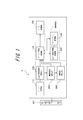
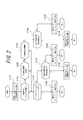
- FIG. 2 is a block diagram of an adaptive array base station according to the first embodiment of the present invention. It is a flowchart which shows the process of the spatial multiplexing slot allocation algorithm (method) by the 1st embodiment of this invention.
- FIG. 6 is a block diagram of an adaptive array base station according to a second embodiment of the present invention. It is a flowchart which shows the process of the spatial multiplexing slot allocation algorithm (method) by the 2nd embodiment of this invention.
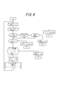
- FIG. 6 is a block diagram of an adaptive array base station according to a third embodiment of the present invention. It is a flowchart which shows the process of the spatial multiplexing slot allocation algorithm (method) by the 3rd embodiment of this invention. It is a timing chart explaining an example of the subslot system by this invention.
- FIG. 1 is a block diagram of an adaptive array base station according to the first embodiment of the present invention.
- the adaptive array base station 1 includes a burst receiving unit 110 that receives an RA burst, a VoIP (narrowband call) determination unit 120 that determines whether or not a VoIP (narrowband call) is performed, and a terminal that has a high speed.
- a burst receiving unit 110 that receives an RA burst
- VoIP (narrowband call) determination unit 120 that determines whether or not a VoIP (narrowband call) is performed
- a terminal that has a high speed.
- a high-speed movement determination unit 180 that determines whether or not the mobile terminal is in a moving state
- a long-distance determination unit 190 that determines whether or not the terminal is far from the local station (adaptive array base station 1)
- a slot that controls slot allocation Allocation control unit 130 maximum spatial multiplexing number managing unit 140, maximum spatial multiplexing number determining unit 140 for determining whether or not the maximum spatial multiplexing number has been reached, subslot managing unit 150, and burst transmitting unit for transmitting AA bursts 160.
- the VoIP (narrowband call) determination unit 120, the high-speed movement determination unit 180, and the long distance determination unit 190 are collectively referred to as a “determination unit”.
- a VoIP (narrowband call) determination unit 120 includes a CPU (Central Processing).
- the unit is included in the control unit A1 configured around a processing device such as a unit (central processing unit).
- the adaptive array base station 1 further includes an adaptive array antenna ANT composed of a plurality of antennas.
- the data flow is shown.
- an RA burst connection request
- the RA burst is transmitted from the terminal side (not shown) to the base station 1 side
- the RA burst is received by the burst receiving unit 110 of the base station 1.
- the VoIP (narrowband call) determination unit 120 reads a VoIP (narrowband call) bit embedded in the RA burst in advance, and determines whether the terminal is a narrowband call terminal such as a VoIP terminal (that is, the terminal call). Indicates that the call is a narrowband call).
- a terminal identification number ID is assigned to each terminal.
- a wideband call or a narrowband call can be determined or designated from the terminal side.
- the terminal need not include the VoIP (narrowband call) bit in the RA burst transmitted to the base station.
- VoIP “narrowband call”
- the determination unit 120 can determine whether the call is a wideband call or a narrowband call based on the terminal identification number ID.
- the high-speed movement determination unit 180 reads the high-speed movement bit embedded in advance in the RA burst, and the terminal It is determined whether the vehicle is moving at high speed (that is, whether the terminal is moving at a predetermined speed or more).
- the high-speed movement determination unit 180 may determine, for example, whether the terminal is moving at high speed from phase changes in a plurality of known signals included in a radio frame, and further, a fading speed (corresponding to movement speed) estimation method is used. You may judge using.
- the long-distance determination unit 190 reads a long-distance connection bit embedded in the RA burst in advance, and the terminal is distant from the base station. (That is, whether or not the terminal is at least a predetermined distance away from its own station (adaptive array base station 1)).
- the long-distance determination unit 190 determines whether the long-distance is based on the information acquired when performing the directivity control of the array antenna ANT acquired during communication with the terminal and the transmission power value to the terminal. be able to. Further, the long distance determination unit 190 transmits information from the terminal regarding the propagation delay time in the received signal received by the terminal and the distance from the own station (adaptive array base station 1) calculated based on the propagation delay time. It is possible to determine whether it is a long distance based on the information regarding. Further, the long distance determination unit 190 can determine whether the long distance is based on the GPS position information transmitted from the terminal.
- the slot allocation control unit 130 refers to the information of the maximum spatial multiplexing number determination unit 140 and the subslot management unit 150 and performs slot allocation control using a spatial multiplexing slot allocation algorithm (method) described in detail later. Do.
- the burst transmission unit 160 notifies the terminal of the allocation result.
- the “full slot” means a normal slot configuration.
- the “subslot” requires only a narrow band such as VoIP.
- a “full slot” is divided into two by time share and used. That is.
- time sharing a method of alternately using even frames and odd frames by two users, or a method of dividing slots into the first half and the second half and using them by two users can be considered. Details of the full slot and the subslot will be described later.
- FIG. 2 is a flowchart showing the processing of the spatial multiplexing slot allocation algorithm (method) according to the first embodiment of the present invention.
- the burst receiving unit 110 of the base station 1 receives an RA burst (connection request) from a terminal.
- the VoIP (narrowband call) determination unit 120 determines whether the terminal is a narrowband call terminal by reading a VoIP (narrowband call) bit embedded in the RA burst in advance (step) S102).
- the high-speed movement determination unit 180 reads a high-speed movement bit embedded in the RA burst in advance. It is determined whether the terminal is a high-speed mobile terminal (step S103). Furthermore, when the determination result of the high-speed movement determination unit 180 indicates that the terminal is not a high-speed mobile terminal, the long-distance determination unit 190 reads a long-distance connection bit embedded in the RA burst in advance, so that the terminal It is determined whether the terminal is a long-distance terminal (step S104).
- slot assignment control section 130 assigns a subslot to the terminal.
- the subslot management unit 150 uses some of the subslots among the subslots obtained by dividing the full slot into a plurality of parts (for example, divided into two) by other narrowband calls. It is determined whether or not there is an empty subslot that is not used (empty subslot with no pair) (step S105).
- the slot allocation control unit 130 transmits an AA burst (subslot allocation) to the terminal by the burst transmission unit 160 so as to allocate the empty subslot to the terminal (step S106)
- the processing of the allocation algorithm is finished.
- step S105 when there is no empty subslot without a pair, the maximum spatial multiplexing number determination unit 140 determines whether or not the carrier frequency when the terminal has transmitted the RA burst has reached the maximum spatial multiplexing. (Step S107). If the maximum spatial multiplexing has not been reached, the process proceeds to step S109, and the slot allocation control unit 130 transmits an AA burst (subslot allocation) to the terminal by the burst transmission unit 160 so as to allocate an arbitrary free subslot to the terminal. Then, the processing of the allocation algorithm is finished.
- AA burst subslot allocation
- step S107 if it is determined in step S107 that the maximum spatial multiplexing has been reached, the slot allocation control unit 130 sends an AA burst (connection rejection) to the terminal by the burst transmission unit 160 so as to reject the connection of the terminal. (Step S108) and the processing of the allocation algorithm is finished.
- Maximum spatial multiplexing number determination section 140 determines whether or not the carrier frequency when the terminal has transmitted the RA burst has reached maximum spatial multiplexing (step S110). If the maximum spatial multiplexing has not been reached, the process proceeds to step S112, and the slot allocation control unit 130 transmits and allocates an AA burst (full slot allocation) to the terminal by the burst transmission unit 160 so as to allocate a full slot to the terminal. Finish the algorithm processing.
- step S110 if it is determined in step S110 that the maximum spatial multiplexing has been reached, the slot allocation control unit 130 sends an AA burst (connection rejection) to the terminal by the burst transmission unit 160 so as to reject the connection of the terminal. Transmit (step S111), and the processing of the allocation algorithm ends.
- all sub-slots are assigned to communication calls from VoIP (narrowband call) terminals with low frequency utilization efficiency, high-speed mobile terminals and long-distance terminals, and other normal data users'
- VoIP narrowband call
- the frequency utilization efficiency of the entire system is greatly improved.
- the frequency utilization efficiency in the spatial multiplexing slot can be expected to be slightly improved.
- the sub-slot switching process is unnecessary, which leads to a reduction in processing load.
- FIG. 3 is a block diagram of an adaptive array base station according to the second embodiment of the present invention.
- the adaptive array base station 2 receives a value indicating the radio quality of the RA burst (connection request) (for example, SINR: Signal-to-Interference and Noise power Ratio).
- a radio quality (SINR) measurement unit 170 to be measured, a VoIP (narrowband call) determination unit 120 that determines whether or not a VoIP (narrowband call) is used, and a value indicating the radio quality of the RA burst (connection request) are predetermined.
- SINR Signal-to-Interference and Noise power Ratio
- a radio quality (SINR) threshold determination unit 200 that determines whether or not the threshold is below the threshold, a slot allocation control unit 130 that controls slot allocation, manages the maximum spatial multiplexing number, and determines whether or not the maximum spatial multiplexing number has been reached.
- a maximum spatial multiplexing number determination unit 140 for determination, a subslot management unit 150, and a burst transmission unit 160 for transmitting an AA burst are provided.
- the VoIP (narrowband call) determination unit 120 and the radio quality (SINR) threshold determination unit 200 are collectively referred to as a “determination unit”.
- a radio quality (SINR) measurement unit 170 a radio quality (SINR) measurement unit 170, a VoIP (narrowband call) determination unit 120, a radio quality (SINR) threshold determination unit 200, a slot allocation control unit 130, a maximum spatial multiplexing number determination unit 140, and a subslot management unit Reference numeral 150 is included in a control unit A2 configured around a processing device such as a CPU (Central Processing Unit).
- the adaptive array base station 2 further includes an adaptive array antenna ANT composed of a plurality of antennas.
- Radio quality (SINR) measurement section 170 measures a value (eg, SINR) indicating the radio quality of the RA burst when receiving the RA burst.
- SINR a value indicating the radio quality of the RA burst when receiving the RA burst.
- An arbitrary radio value other than SINR can be used as a value indicating the radio quality.
- the radio quality (SINR) measurement unit 170 may measure (acquire) radio quality by reading a radio quality value embedded in advance in the RA burst, for example.
- the VoIP (narrowband call) determination unit 120 reads a VoIP (narrowband call) bit embedded in advance in the RA burst, and determines whether the terminal is a narrowband call terminal such as a VoIP terminal (that is, the terminal call). Indicates that the call is a narrowband call).
- a terminal identification number ID is assigned to each terminal.
- a wideband call or a narrowband call can be determined or designated from the terminal side. it can.
- the VoIP (narrowband call) determination unit 120 can determine whether the call is a wideband call or a narrowband call based on the terminal identification number ID.
- the radio quality (SINR) threshold determination unit 200 determines the RA measured by the radio quality (SINR) measurement unit 170. It is determined whether the value indicating the radio quality of the burst is equal to or less than a predetermined threshold.
- the slot allocation control unit 130 refers to the information of the maximum spatial multiplexing number determination unit 140 and the subslot management unit 150 and performs slot allocation control using a spatial multiplexing slot allocation algorithm (method) described in detail later. Do.
- the burst transmission unit 160 notifies the terminal of the allocation result.
- the “full slot” means a normal slot configuration.
- the “subslot” requires only a narrow band such as VoIP.
- a “full slot” is divided into two by time share and used. That is.
- a time sharing method a method of alternately using even frames and odd frames by two users, or a method of dividing slots into the first half and the second half and using them by two users can be considered. Details of the full slot and the subslot will be described later.
- FIG. 4 is a flowchart showing processing of a spatial multiplex slot allocation algorithm (method) according to the second embodiment of the present invention.
- the burst receiving unit 110 of the base station 2 receives the RA burst (connection request) from the terminal, and the radio quality ( SINR) measuring section 170 measures a value (eg, SINR) indicating the radio quality of the RA burst.
- the VoIP (narrowband call) determination unit 120 determines whether the terminal is a narrowband call terminal by reading a VoIP (narrowband call) bit embedded in the RA burst in advance (step) S202).
- the radio quality (SINR) threshold determination unit 200 determines the RA measured by the radio quality (SINR) measurement unit 170. It is determined whether or not the value indicating the radio quality of the burst is equal to or less than a predetermined threshold (step S203).
- step S202 If it is determined in step S202 that the terminal is a narrowband call terminal, or if it is determined in step S203 that the value of the radio quality is equal to or less than a predetermined threshold, the slot allocation control unit 130 On the other hand, control is performed so as to allocate subslots.
- the subslot management unit 150 uses some of the subslots among the subslots obtained by dividing the full slot into a plurality of parts (for example, divided into two) by other narrowband calls. It is determined whether there is an empty subslot that is not used (empty subslot with no pair) (step S204).
- the slot allocation control unit 130 transmits an AA burst (subslot allocation) to the terminal by the burst transmission unit 160 so as to allocate the empty subslot to the terminal (step S205)
- the processing of the allocation algorithm is finished.
- step S204 when there is no empty subslot without a pair, the maximum spatial multiplexing number determination unit 140 determines whether the carrier frequency when the terminal has transmitted the RA burst has reached the maximum spatial multiplexing. (Step S206). If the maximum spatial multiplexing has not been reached, the process proceeds to step S208, and the slot allocation control unit 130 transmits an AA burst (subslot allocation) to the terminal by the burst transmission unit 160 so as to allocate an arbitrary empty subslot to the terminal. Then, the processing of the allocation algorithm is finished.
- AA burst subslot allocation
- step S206 if it is determined in step S206 that the maximum spatial multiplexing has been reached, the slot allocation control unit 130 sends an AA burst (connection rejection) to the terminal by the burst transmission unit 160 so as to reject the connection of the terminal. (Step S207) and the processing of the allocation algorithm is finished.
- step S202 If it is not determined in step S202 that the terminal is a narrowband call terminal, and it is further determined in step S203 that the wireless quality value satisfies a predetermined threshold (that is, the call from the terminal requires full slot allocation).
- the maximum spatial multiplexing number determination unit 140 indicates that the carrier frequency when the terminal has transmitted the RA burst has reached the maximum spatial multiplexing. It is determined whether or not there is (step S209). If the maximum spatial multiplexing has not been reached, the process proceeds to step S211 and the slot allocation control unit 130 transmits and allocates an AA burst (full slot allocation) to the terminal by the burst transmission unit 160 so as to allocate a full slot to the terminal. Finish the algorithm processing.
- step S209 if it is determined in step S209 that the maximum spatial multiplexing has been reached, the slot allocation control unit 130 sends an AA burst (connection rejection) to the terminal by the burst transmission unit 160 so as to reject the connection of the terminal. (Step S210) and the processing of the allocation algorithm is finished.
- communication calls from VoIP (narrowband call) terminals with low frequency utilization efficiency and communication calls from terminals with poor radio quality are all allocated to subslots, and other normal data other than that.
- VoIP narrowband call
- communication calls from terminals with poor radio quality are all allocated to subslots, and other normal data other than that.
- all communication calls from terminals with poor radio quality are allocated to subslots, so that interference with other terminals by such terminals can be reduced, and the frequency utilization efficiency of the entire system can be improved. Can be expected.
- FIG. 5 is a block diagram of an adaptive array base station according to the third embodiment of the present invention.
- the adaptive array base station 3 receives a value indicating the radio quality of the RA burst (connection request) (for example, SINR: Signal-to-Interference and Noise power Ratio).
- SINR Signal-to-Interference and Noise power Ratio
- Radio quality (SINR) measurement unit 170 to be measured VoIP (narrowband call) determination unit 120 that determines whether or not a VoIP (narrowband call) is performed, and high-speed movement that determines whether or not the terminal is in a high-speed movement state
- a determination unit 180 a long distance determination unit 190 that determines whether or not the terminal is a long distance from the own station (adaptive array base station 3), and a value indicating the radio quality of the RA burst (connection request) is equal to or less than a predetermined threshold
- a radio quality (SINR) threshold determination unit 200 for determining whether or not there exists, a slot allocation control unit 130 for controlling slot allocation, a maximum spatial multiplexing number, and a maximum for determining whether or not the maximum spatial multiplexing number has been reached Spatial multiple number Comprising a tough 140, burst transmission unit 160 that transmits the sub-slot management unit 150, and the AA burst.
- the VoIP (narrowband call) determination unit 120, the high-speed movement determination unit 180, the long-distance determination unit 190, and the radio quality (SINR) threshold determination unit 200 are collectively referred to as a “determination unit”. Also, a radio quality (SINR) measurement unit 170, a VoIP (narrowband call) determination unit 120, a high-speed movement determination unit 180, a long distance determination unit 190, a radio quality (SINR) threshold determination unit 200, a slot allocation control unit 130, a maximum The spatial multiplexing number determination unit 140 and the subslot management unit 150 are included in a control unit A3 configured mainly with a processing device such as a CPU (Central Processing Unit).
- the adaptive array base station 3 further includes an adaptive array antenna ANT composed of a plurality of antennas.
- Radio quality (SINR) measurement section 170 measures a value (eg, SINR) indicating the radio quality of the RA burst when receiving the RA burst.
- SINR a value indicating the radio quality of the RA burst when receiving the RA burst.
- An arbitrary radio value other than SINR can be used as a value indicating the radio quality.
- the radio quality (SINR) measurement unit 170 may measure (acquire) radio quality by reading a radio quality value embedded in advance in the RA burst, for example.
- the VoIP (narrowband call) determination unit 120 reads a VoIP (narrowband call) bit embedded in advance in the RA burst, and determines whether the terminal is a narrowband call terminal such as a VoIP terminal (that is, the terminal call). Indicates that the call is a narrowband call).
- a terminal identification number ID is assigned to each terminal.
- a wideband call or a narrowband call can be determined or designated from the terminal side.
- the terminal does not need to include the VoIP (narrowband call) bit in the RA burst transmitted to the base station, but if the terminal identification number ID at the time of registration is included, VoIP (narrowband call)
- the determination unit 120 can determine whether the call is a wideband call or a narrowband call based on the terminal identification number ID.
- the high-speed movement determination unit 180 reads the high-speed movement bit embedded in advance in the RA burst, and the terminal It is determined whether the vehicle is moving at high speed (that is, whether the terminal is moving at a predetermined speed or more).
- the high-speed movement determination unit 180 may determine, for example, whether the terminal is moving at high speed from phase changes in a plurality of known signals included in a radio frame, and further, a fading speed (corresponding to movement speed) estimation method is used. You may judge using.
- the long-distance determination unit 190 reads a long-distance connection bit embedded in the RA burst in advance, and the terminal is distant from the base station. (That is, whether or not the terminal is at least a predetermined distance away from the own station (adaptive array base station 3)).
- the long-distance determination unit 190 determines whether the long-distance is based on the information acquired when performing the directivity control of the array antenna ANT acquired during communication with the terminal and the transmission power value to the terminal. be able to. Further, the long distance determination unit 190 transmits information from the terminal regarding the propagation delay time in the received signal received by the terminal, and the distance from the own station (adaptive array base station 3) calculated based on the propagation delay time. It is possible to determine whether it is a long distance based on the information regarding. Further, the long distance determination unit 190 can determine whether or not it is a long distance based on GPS position information transmitted from the terminal.
- the radio quality (SINR) threshold determination unit 200 It is determined whether the value indicating the radio quality of the RA burst measured by the quality (SINR) measurement unit 170 is equal to or less than a predetermined threshold.
- the slot allocation control unit 130 refers to the information of the maximum spatial multiplexing number determination unit 140 and the subslot management unit 150 and performs slot allocation control using a spatial multiplexing slot allocation algorithm (method) described in detail later. Do.
- the burst transmission unit 160 notifies the terminal of the allocation result.
- the “full slot” means a normal slot configuration.
- the “subslot” requires only a narrow band such as VoIP.
- a “full slot” is divided into two by time share and used. That is.
- time sharing a method of alternately using even frames and odd frames by two users, or a method of dividing slots into the first half and the second half and using them by two users can be considered. Details of the full slot and the subslot will be described later.
- FIG. 6 is a flowchart showing processing of a spatial multiplex slot allocation algorithm (method) according to the third embodiment of the present invention.
- the burst receiving unit 110 of the base station 3 receives the RA burst (connection request) from the terminal, and the radio quality ( SINR) measuring section 170 measures a value (eg, SINR) indicating the radio quality of the RA burst.
- the VoIP (narrowband call) determination unit 120 determines whether the terminal is a narrowband call terminal by reading a VoIP (narrowband call) bit embedded in the RA burst in advance (step) S302).
- the high-speed movement determination unit 180 reads a high-speed movement bit embedded in the RA burst in advance. It is determined whether the terminal is a high-speed mobile terminal (step S303). Furthermore, when the determination result of the high-speed movement determination unit 180 indicates that the terminal is not a high-speed mobile terminal, the long-distance determination unit 190 reads a long-distance connection bit embedded in the RA burst in advance, so that the terminal It is determined whether the terminal is a long-distance terminal (step S304).
- a radio quality (SINR) threshold value The determination unit 200 determines whether the value indicating the radio quality of the RA burst measured by the radio quality (SINR) measurement unit 170 is equal to or less than a predetermined threshold (step S305).
- step S302 If it is determined in step S302 that the terminal is a narrowband call terminal, and in steps S303 to S305, the terminal is either a high-speed mobile terminal or a long-distance terminal, and the wireless quality value is a predetermined value.
- the slot allocation control unit 130 performs control so as to allocate a subslot to the terminal.
- the subslot management unit 150 uses some of the subslots among the subslots obtained by dividing the full slot into a plurality of parts (for example, divided into two) by other narrowband calls. It is determined whether there is an empty subslot that is not used (empty subslot with no pair) (step S306).
- the slot allocation control unit 130 transmits an AA burst (subslot allocation) to the terminal by the burst transmission unit 160 so as to allocate the empty subslot to the terminal (step S307) The processing of the allocation algorithm is finished.
- step S306 when there is no empty subslot with no pair, the maximum spatial multiplexing number determination unit 140 determines whether the carrier frequency when the terminal has transmitted the RA burst has reached the maximum spatial multiplexing. (Step S308). If the maximum spatial multiplexing has not been reached, the process proceeds to step S310, and the slot allocation control unit 130 transmits an AA burst (subslot allocation) to the terminal by the burst transmission unit 160 so as to allocate an arbitrary empty subslot to the terminal. Then, the processing of the allocation algorithm is finished.
- AA burst subslot allocation
- step S308 if it is determined in step S308 that the maximum spatial multiplexing has been reached, the slot allocation control unit 130 sends an AA burst (connection rejection) to the terminal by the burst transmission unit 160 so as to reject the connection of the terminal. Transmit (step S310), and the processing of the allocation algorithm is finished.
- steps S302 to S304 if it is not determined that the terminal is a narrowband call terminal, a high-speed mobile terminal, or a long-distance terminal (that is, if the call from the terminal is a wideband call that requires full slot allocation), In steps S303 to S305, if the terminal is either a high-speed mobile terminal or a long-distance terminal, but it is determined that the wireless quality value satisfies a predetermined threshold (that is, the high-speed mobile terminal or the long-distance terminal When full slot allocation is possible, maximum spatial multiplexing number determination section 140 determines whether or not the carrier frequency when the terminal has transmitted the RA burst has reached maximum spatial multiplexing (step S311).
- step S313 the slot allocation control unit 130 transmits and allocates an AA burst (full slot allocation) to the terminal by the burst transmission unit 160 so as to allocate a full slot to the terminal. Finish the algorithm processing.
- the slot allocation control unit 130 sends an AA burst (connection rejection) to the terminal by the burst transmission unit 160 so as to reject the connection of the terminal. (Step S312) and the processing of the allocation algorithm is finished.
- all communication calls from VoIP (narrowband call) terminals with low frequency utilization efficiency, high-speed mobile terminals and terminals with poor radio quality are allocated to subslots.
- VoIP narrowband call
- a significant improvement can be expected in terms of frequency utilization efficiency of the entire system.
- a full slot is allocated to a terminal with good radio quality. Therefore, a high radio throughput can be provided to a user of the terminal, and frequency utilization efficiency can be improved. Improvement is expected.
- a communication call from a high-speed mobile terminal and a long-distance terminal having poor radio quality is assigned to a subslot, it is possible to reduce interference with other terminals by the terminal.
- the frequency utilization efficiency of the entire system can be expected to improve.
- FIG. 7 is a timing chart for explaining an example of the sub-slot method according to the present invention.
- FIG. 7 (a) shows the original time slot (full slot) of the full slot system, where the upper Tx when viewed from the base station is the time slots # 1 to # 3 on the transmission side, and the lower Rx Are time slots # 1 to # 3 on the receiving side, which are asymmetric time intervals.
- FIG. 7B shows a state in which full slots are divided into subslots by dividing the allocation of full slots into frames with a certain fixed period, such as even frames and odd frames.
- slot # 1 of frame F1 which is an odd frame
- slot # 1 of frame F3 is assigned as subslot SS12.
- slot # 1 of frame F2 which is an even frame
- slot # 1 of frame F4 is assigned as subslot SS22.
- FIG. 7 (c) shows a method of dividing one time slot into a first half and a second half to form subslots.
- User 1 is assigned the first half of slot # 1 of each frame F1 to F4 as subslots SS31 to SS34.
- the second half of slot # 1 of each frame F1 to F4 is assigned to user 2 as subslots SS41 to SS44.
- the slot on the receiving side which is half the bandwidth of the slot on the transmitting side, is left as a full slot, and if any user's slot is temporarily shared, communication quality and communication by subslotting Area degradation can be kept to a minimum.
- the adaptive array base station and the control method thereof for example, communication in which all the connections of spatial multiplexing slots are assigned subslots such as narrowband call terminals such as VoIP, long-distance terminals, and high-speed mobile terminals
- narrowband call terminals such as VoIP, long-distance terminals, and high-speed mobile terminals
- full slots are allocated until the maximum number of spatial multiplexing is reached as before, so assigning narrowband call terminals etc. to subslots may affect the communication quality of users of wideband calls. Absent.
- each part, each means, each step, etc. can be rearranged so that there is no logical contradiction, and it is possible to combine or divide a plurality of means, steps, etc. into one. It is.
- the sub-slot allocation has been described with reference to only the frame on the transmission side, but it should be noted that the slot can be allocated in the same manner even for the reception slot.
- sub-slotting by dividing a full slot is divided into two frames, such as an odd frame and an even frame, and a format in which one full slot is divided into two parts, the first half and the second half.
- it may be a format that is divided into more subslots such as three divisions or four divisions.
- Adaptive array base station 110 Burst receiver 120 VoIP (narrowband call) determination unit 130 Slot allocation control unit 140 Maximum spatial multiplexing number determination unit 150 Subslot management unit 160 Burst transmission unit 170 Radio quality (SINR) measurement Unit 180 high-speed movement determination unit 190 long-range determination unit 200 radio quality (SINR) threshold determination unit A1, A2, A3 control unit ANT adaptive array antenna SS11, SS12 subslot SS21, SS22 subslot SS31-SS34 subslot SS41-SS44 sub slot
Landscapes
- Engineering & Computer Science (AREA)
- Computer Networks & Wireless Communication (AREA)
- Signal Processing (AREA)
- Mobile Radio Communication Systems (AREA)
- Radio Transmission System (AREA)
Abstract
Description
複数の端末と通信を行う基地局の空間多重スロット割当方法であって、
端末から送信される接続要求を受信する受信ステップと、
前記接続要求から前記端末の状態、又は、前記接続要求の無線品質の少なくとも一方を判定する判定ステップと、
前記判定ステップの判定結果に応じて、前記端末に対して、サブスロット方式又はフルスロット方式でスロットを割当てる割当制御ステップと、を含むものである。
前記判定ステップは、
前記接続要求が、前記端末の呼が狭帯域呼であることを示すか、前記端末が所定速度以上で移動していることを示すか、又は、前記端末が自局と所定距離以上離れていることを示すか、を判定し、
前記割当制御ステップは、
前記判定ステップにおいて、前記端末の呼が狭帯域呼であることを示すか、前記端末が所定速度以上で移動していることを示すか、又は、前記端末が自局と所定距離以上離れていることを示すと判定された場合に、前記端末に対して、サブスロット方式でスロットを割当て、他の場合には、前記端末に対して、フルスロット方式でスロットを割当てる、
ことを特徴とするものである。
前記判定ステップは、
前記接続要求が、前記端末の呼が狭帯域呼であることを示すか、又は、前記接続要求の無線品質を示す値が所定値以下であるか、を判定し、
前記割当制御ステップは、
前記判定ステップにおいて、前記端末の呼が狭帯域呼であることを示すか、又は、前記接続要求の無線品質を示す値が所定値以下であると判定された場合に、前記端末に対して、サブスロット方式でスロットを割当て、他の場合には、前記端末に対して、フルスロット方式でスロットを割当てる、
ことを特徴とするものである。
前記判定ステップは、
前記接続要求が、前記端末の呼が狭帯域呼であることを示すか、前記端末が所定速度以上で移動していることを示すか、前記端末が自局と所定距離以上離れていることを示すか、又は、前記接続要求の無線品質を示す値が所定値以下であることを示すか、を判定し、
前記割当制御ステップは、
前記判定ステップにおいて、
-前記端末の呼が狭帯域呼であることを示すと判定される場合か、
-前記端末が所定速度以上で移動していることを示すか、又は、前記端末が自局と所定距離以上離れていることを示すと判定され、かつ、前記接続要求の無線品質を示す値が所定値以下であると判定される場合に、
前記端末に対して、サブスロット方式でスロットを割当て、他の場合には、前記端末に対して、フルスロット方式でスロットを割当てる、
ことを特徴とするものである。
前記端末にサブスロット方式でスロットを割当てる場合に、自局の空間多重スロットにおいて、フルスロットを複数に分割したサブスロットのうち、一部のサブスロットが使用中であり、他のサブスロットは未使用であるという空きサブスロットがあるかどうかを判定するサブスロット管理ステップをさらに含み、
前記割当制御ステップは、前記サブスロット管理ステップにおいて空きサブスロットがあると判定された場合、当該空きサブスロットを前記端末に割当てる割当制御を行う、ことを特徴とするものである。
空間多重スロット割当方式で複数の端末と通信を行う基地局であって、
端末から送信される接続要求を受信する受信部と、
前記接続要求に応じて、前記端末に対して、サブスロット方式又はフルスロット方式でスロットを割当てる制御部と、を備えるものである。
前記制御部は、前記接続要求が、前記端末の呼が狭帯域呼であることを示すか、前記端末が所定速度以上で移動していることを示すか、又は、前記端末が自局と所定距離以上離れていることを示す場合に、前記端末に対して、サブスロット方式でスロットを割当て、他の場合には、前記端末に対して、フルスロット方式でスロットを割当てる、
ことを特徴とするものである。
前記制御部は、前記接続要求が、前記端末の呼が狭帯域呼であることを示すか、又は、前記接続要求の無線品質を示す値が所定値以下である場合に、前記端末に対して、サブスロット方式でスロットを割当て、他の場合には、前記端末に対して、フルスロット方式でスロットを割当てる、
ことを特徴とするものである。
前記制御部は、前記接続要求が、
-前記端末の呼が狭帯域呼であることを示す場合か、
-前記端末が所定速度以上で移動していることを示すか、又は、前記端末が自局と所定距離以上離れていることを示し、かつ、前記接続要求の無線品質を示す値が所定値以下であることを示す場合に、
前記端末に対して、サブスロット方式でスロットを割当て、他の場合には、前記端末に対して、フルスロット方式でスロットを割当てる
ことを特徴とするものである。
前記制御部は、前記端末にサブスロット方式でスロットを割当てる場合、自局の空間多重スロットにおいて、フルスロットを複数に分割したサブスロットのうち、一部のサブスロットが使用中であり、他のサブスロットは未使用であるという空きサブスロットがあるときには、当該空きサブスロットを前記端末に割当てる割当制御を行う、
ことを特徴とするものである。
図1は、本発明の第1の実施態様に係るアダプティブアレイ基地局のブロック図である。図に示すように、アダプティブアレイ基地局1は、RAバーストを受信するバースト受信部110、VoIP(狭帯域呼)であるか否かを判定するVoIP(狭帯域呼)判定部120、端末が高速移動状態にあるか否かを判定する高速移動判定部180、端末が自局(アダプティブアレイ基地局1)から遠距離であるか否かを判定する遠距離判定部190、スロット割当を制御するスロット割当制御部130、最大空間多重数を管理し、最大空間多重数に到達しているか否かを判定する最大空間多重数判定部140、サブスロット管理部150、及びAAバーストを送信するバースト送信部160を備える。なお、VoIP(狭帯域呼)判定部120、高速移動判定部180、及び遠距離判定部190をまとめて「判定部」というものとする。また、VoIP(狭帯域呼)判定部120、高速移動判定部180、遠距離判定部190、スロット割当制御部130、最大空間多重数判定部140、及びサブスロット管理部150は、CPU(Central Processing Unit:中央処理装置)等の処理装置を中心として構成された制御部A1に含まれる。また、アダプティブアレイ基地局1は、複数のアンテナからなるアダプティブアレイアンテナANTをさらに備える。
図3は、本発明の第2の実施態様によるアダプティブアレイ基地局のブロック図である。図に示すように、アダプティブアレイ基地局2は、RAバーストを受信するバースト受信部110、RAバースト(接続要求)の無線品質を示す値(例えばSINR:Signal-to-Interference and Noise power Ratio)を測定する無線品質(SINR)測定部170、VoIP(狭帯域呼)であるか否かを判定するVoIP(狭帯域呼)判定部120、RAバースト(接続要求)の無線品質を示す値が所定の閾値以下であるかどうかを判定する無線品質(SINR)閾値判定部200、スロット割当を制御するスロット割当制御部130、最大空間多重数を管理し、最大空間多重数に到達しているか否かを判定する最大空間多重数判定部140、サブスロット管理部150、及びAAバーストを送信するバースト送信部160を備える。なお、VoIP(狭帯域呼)判定部120及び無線品質(SINR)閾値判定部200をまとめて「判定部」というものとする。また、無線品質(SINR)測定部170、VoIP(狭帯域呼)判定部120、無線品質(SINR)閾値判定部200、スロット割当制御部130、最大空間多重数判定部140、及びサブスロット管理部150は、CPU(Central Processing Unit:中央処理装置)等の処理装置を中心として構成された制御部A2に含まれる。また、アダプティブアレイ基地局2は、複数のアンテナからなるアダプティブアレイアンテナANTをさらに備える。
図5は、本発明の第3の実施態様によるアダプティブアレイ基地局のブロック図である。図に示すように、アダプティブアレイ基地局3は、RAバーストを受信するバースト受信部110、RAバースト(接続要求)の無線品質を示す値(例えばSINR:Signal-to-Interference and Noise power Ratio)を測定する無線品質(SINR)測定部170、VoIP(狭帯域呼)であるか否かを判定するVoIP(狭帯域呼)判定部120、端末が高速移動状態にあるか否かを判定する高速移動判定部180、端末が自局(アダプティブアレイ基地局3)から遠距離であるか否かを判定する遠距離判定部190、RAバースト(接続要求)の無線品質を示す値が所定の閾値以下であるかどうかを判定する無線品質(SINR)閾値判定部200、スロット割当を制御するスロット割当制御部130、最大空間多重数を管理し、最大空間多重数に到達しているか否かを判定する最大空間多重数判定部140、サブスロット管理部150、及びAAバーストを送信するバースト送信部160を備える。なお、VoIP(狭帯域呼)判定部120、高速移動判定部180、遠距離判定部190、及び無線品質(SINR)閾値判定部200をまとめて「判定部」というものとする。また、無線品質(SINR)測定部170、VoIP(狭帯域呼)判定部120、高速移動判定部180、遠距離判定部190、無線品質(SINR)閾値判定部200、スロット割当制御部130、最大空間多重数判定部140、及びサブスロット管理部150は、CPU(Central Processing Unit:中央処理装置)等の処理装置を中心として構成された制御部A3に含まれる。また、アダプティブアレイ基地局3は、複数のアンテナからなるアダプティブアレイアンテナANTをさらに備える。
110 バースト受信部
120 VoIP(狭帯域呼)判定部
130 スロット割当制御部
140 最大空間多重数判定部
150 サブスロット管理部
160 バースト送信部
170 無線品質(SINR)測定部
180 高速移動判定部
190 遠距離判定部
200 無線品質(SINR)閾値判定部
A1、A2、A3 制御部
ANT アダプティブアレイアンテナ
SS11、SS12 サブスロット
SS21、SS22 サブスロット
SS31-SS34 サブスロット
SS41-SS44 サブスロット
Claims (10)
- 複数の端末と通信を行う基地局の空間多重スロット割当方法であって、
端末から送信される接続要求を受信する受信ステップと、
前記接続要求から前記端末の状態、又は、前記接続要求の無線品質の少なくとも一方を判定する判定ステップと、
前記判定ステップの判定結果に応じて、前記端末に対して、サブスロット方式又はフルスロット方式でスロットを割当てる割当制御ステップと、を含む空間多重スロット割当方法。 - 請求項1に記載の空間多重スロット割当方法であって、
前記判定ステップは、
前記接続要求が、前記端末の呼が狭帯域呼であることを示すか、前記端末が所定速度以上で移動していることを示すか、又は、前記端末が自局と所定距離以上離れていることを示すか、を判定し、
前記割当制御ステップは、
前記判定ステップにおいて、前記端末の呼が狭帯域呼であることを示すか、前記端末が所定速度以上で移動していることを示すか、又は、前記端末が自局と所定距離以上離れていることを示すと判定された場合に、前記端末に対して、サブスロット方式でスロットを割当て、他の場合には、前記端末に対して、フルスロット方式でスロットを割当てる、
ことを特徴とする空間多重スロット割当方法。 - 請求項1に記載の空間多重スロット割当方法であって、
前記判定ステップは、
前記接続要求が、前記端末の呼が狭帯域呼であることを示すか、又は、前記接続要求の無線品質を示す値が所定値以下であるか、を判定し、
前記割当制御ステップは、
前記判定ステップにおいて、前記端末の呼が狭帯域呼であることを示すか、又は、前記接続要求の無線品質を示す値が所定値以下であると判定された場合に、前記端末に対して、サブスロット方式でスロットを割当て、他の場合には、前記端末に対して、フルスロット方式でスロットを割当てる、
ことを特徴とする空間多重スロット割当方法。 - 請求項1に記載の空間多重スロット割当方法であって、
前記判定ステップは、
前記接続要求が、前記端末の呼が狭帯域呼であることを示すか、前記端末が所定速度以上で移動していることを示すか、前記端末が自局と所定距離以上離れていることを示すか、又は、前記接続要求の無線品質を示す値が所定値以下であることを示すか、を判定し、
前記割当制御ステップは、
前記判定ステップにおいて、
-前記端末の呼が狭帯域呼であることを示すと判定される場合か、
-前記端末が所定速度以上で移動していることを示すか、又は、前記端末が自局と所定距離以上離れていることを示すと判定され、かつ、前記接続要求の無線品質を示す値が所定値以下であると判定される場合に、
前記端末に対して、サブスロット方式でスロットを割当て、他の場合には、前記端末に対して、フルスロット方式でスロットを割当てる、
ことを特徴とする空間多重スロット割当方法。 - 請求項1乃至4のいずれか一項に記載の空間多重スロット割当方法であって、
前記端末にサブスロット方式でスロットを割当てる場合に、自局の空間多重スロットにおいて、フルスロットを複数に分割したサブスロットのうち、一部のサブスロットが使用中であり、他のサブスロットは未使用であるという空きサブスロットがあるかどうかを判定するサブスロット管理ステップをさらに含み、
前記割当制御ステップは、前記サブスロット管理ステップにおいて空きサブスロットがあると判定された場合、当該空きサブスロットを前記端末に割当てる割当制御を行う、ことを特徴とする空間多重スロット割当方法。 - 空間多重スロット割当方式で複数の端末と通信を行う基地局であって、
端末から送信される接続要求を受信する受信部と、
前記接続要求に応じて、前記端末に対して、サブスロット方式又はフルスロット方式でスロットを割当てる制御部と、を備える基地局。 - 請求項6に記載の基地局であって、
前記制御部は、前記接続要求が、前記端末の呼が狭帯域呼であることを示すか、前記端末が所定速度以上で移動していることを示すか、又は、前記端末が自局と所定距離以上離れていることを示す場合に、前記端末に対して、サブスロット方式でスロットを割当て、他の場合には、前記端末に対して、フルスロット方式でスロットを割当てる、
ことを特徴とする基地局。 - 請求項6に記載の基地局であって、
前記制御部は、前記接続要求が、前記端末の呼が狭帯域呼であることを示すか、又は、前記接続要求の無線品質を示す値が所定値以下である場合に、前記端末に対して、サブスロット方式でスロットを割当て、他の場合には、前記端末に対して、フルスロット方式でスロットを割当てる、
ことを特徴とする基地局。 - 請求項6に記載の基地局であって、
前記制御部は、前記接続要求が、
-前記端末の呼が狭帯域呼であることを示す場合か、
-前記端末が所定速度以上で移動していることを示すか、又は、前記端末が自局と所定距離以上離れていることを示し、かつ、前記接続要求の無線品質を示す値が所定値以下であることを示す場合に、
前記端末に対して、サブスロット方式でスロットを割当て、他の場合には、前記端末に対して、フルスロット方式でスロットを割当てる
ことを特徴とする基地局。 - 請求項6乃至9のいずれか一項に記載の基地局であって、
前記制御部は、前記端末にサブスロット方式でスロットを割当てる場合、自局の空間多重スロットにおいて、フルスロットを複数に分割したサブスロットのうち、一部のサブスロットが使用中であり、他のサブスロットは未使用であるという空きサブスロットがあるときには、当該空きサブスロットを前記端末に割当てる割当制御を行う、
ことを特徴とする基地局。
Priority Applications (2)
| Application Number | Priority Date | Filing Date | Title |
|---|---|---|---|
| JP2010540379A JPWO2010061614A1 (ja) | 2008-11-26 | 2009-11-26 | 空間多重スロット割当方法および基地局 |
| US13/129,223 US20110211550A1 (en) | 2008-11-26 | 2009-11-26 | Spatial multiplexing slot assignment method and base station |
Applications Claiming Priority (6)
| Application Number | Priority Date | Filing Date | Title |
|---|---|---|---|
| JP2008-301370 | 2008-11-26 | ||
| JP2008301370 | 2008-11-26 | ||
| JP2009-016872 | 2009-01-28 | ||
| JP2009-016780 | 2009-01-28 | ||
| JP2009016872 | 2009-01-28 | ||
| JP2009016780 | 2009-01-28 |
Publications (1)
| Publication Number | Publication Date |
|---|---|
| WO2010061614A1 true WO2010061614A1 (ja) | 2010-06-03 |
Family
ID=42225499
Family Applications (1)
| Application Number | Title | Priority Date | Filing Date |
|---|---|---|---|
| PCT/JP2009/006401 Ceased WO2010061614A1 (ja) | 2008-11-26 | 2009-11-26 | 空間多重スロット割当方法および基地局 |
Country Status (3)
| Country | Link |
|---|---|
| US (1) | US20110211550A1 (ja) |
| JP (1) | JPWO2010061614A1 (ja) |
| WO (1) | WO2010061614A1 (ja) |
Cited By (1)
| Publication number | Priority date | Publication date | Assignee | Title |
|---|---|---|---|---|
| JP2014068177A (ja) * | 2012-09-26 | 2014-04-17 | Nippon Telegr & Teleph Corp <Ntt> | 基地局装置、無線通信方法、及び無線通信システム |
Families Citing this family (2)
| Publication number | Priority date | Publication date | Assignee | Title |
|---|---|---|---|---|
| US9661615B2 (en) * | 2013-04-09 | 2017-05-23 | Motorola Solutions, Inc. | Method and apparatus for managing trunking operations in an ad-hoc network |
| WO2018199135A1 (ja) * | 2017-04-28 | 2018-11-01 | 株式会社Nttドコモ | 無線基地局 |
Citations (2)
| Publication number | Priority date | Publication date | Assignee | Title |
|---|---|---|---|---|
| JP2008085800A (ja) * | 2006-09-28 | 2008-04-10 | Kyocera Corp | 空間多重スロット割当方法およびアダプティブアレイ基地局 |
| JP2008160823A (ja) * | 2006-11-29 | 2008-07-10 | Kyocera Corp | 空間多重スロット割当方法およびアダプティブアレイ基地局 |
Family Cites Families (6)
| Publication number | Priority date | Publication date | Assignee | Title |
|---|---|---|---|---|
| US7006477B1 (en) * | 1999-12-10 | 2006-02-28 | Lucent Technologies Inc. | Method for interleaving of half rate channels suitable for half duplex operation and statistical multiplexing |
| US7532904B2 (en) * | 2004-06-04 | 2009-05-12 | Broadcom Corporation | Adaptive piconet protocol |
| WO2007074841A1 (ja) * | 2005-12-28 | 2007-07-05 | Matsushita Electric Industrial Co., Ltd. | 無線送信装置及び無線送信方法 |
| EP2056505B1 (en) * | 2006-07-07 | 2014-08-27 | Mitsubishi Electric Corporation | Wireless communication system |
| KR20090118074A (ko) * | 2007-03-01 | 2009-11-17 | 가부시키가이샤 엔티티 도코모 | 기지국장치 및 통신제어방법 |
| CN101669395A (zh) * | 2007-03-01 | 2010-03-10 | 株式会社Ntt都科摩 | 基站装置和通信控制方法 |
-
2009
- 2009-11-26 JP JP2010540379A patent/JPWO2010061614A1/ja active Pending
- 2009-11-26 US US13/129,223 patent/US20110211550A1/en not_active Abandoned
- 2009-11-26 WO PCT/JP2009/006401 patent/WO2010061614A1/ja not_active Ceased
Patent Citations (2)
| Publication number | Priority date | Publication date | Assignee | Title |
|---|---|---|---|---|
| JP2008085800A (ja) * | 2006-09-28 | 2008-04-10 | Kyocera Corp | 空間多重スロット割当方法およびアダプティブアレイ基地局 |
| JP2008160823A (ja) * | 2006-11-29 | 2008-07-10 | Kyocera Corp | 空間多重スロット割当方法およびアダプティブアレイ基地局 |
Cited By (1)
| Publication number | Priority date | Publication date | Assignee | Title |
|---|---|---|---|---|
| JP2014068177A (ja) * | 2012-09-26 | 2014-04-17 | Nippon Telegr & Teleph Corp <Ntt> | 基地局装置、無線通信方法、及び無線通信システム |
Also Published As
| Publication number | Publication date |
|---|---|
| US20110211550A1 (en) | 2011-09-01 |
| JPWO2010061614A1 (ja) | 2012-04-26 |
Similar Documents
| Publication | Publication Date | Title |
|---|---|---|
| EP3831136B1 (en) | Receiver-based sidelink resource selection | |
| US7822421B2 (en) | Apparatus and method for use in allocating a channel resource in wireless multiple access communications systems | |
| CN107534871B (zh) | 用于跟踪信道的系统及方法 | |
| US9191987B2 (en) | Determining “fair share” of radio resources in radio access system with contention-based spectrum sharing | |
| EP3637935B1 (en) | Channel interception method, network side device and terminal | |
| CN104427632B (zh) | 数据传输调度方法、装置和系统 | |
| US20100009695A1 (en) | Communication system to perform lending and/or borrowing of a radio resource | |
| US20050159162A1 (en) | Method for transmitting data in mobile communication network | |
| US20140295858A1 (en) | User equipment and method for distributed channel access for d2d communications | |
| KR102109709B1 (ko) | 5G 네트워크에서 eMBB와 uRLLC의 공존을 위한 방법 및 시스템 | |
| KR101897117B1 (ko) | 통신 시스템에서 채널 할당 장치 및 방법 | |
| KR20120073147A (ko) | 단말간의 직접통신을 수행하는 방법 | |
| US20100215009A1 (en) | Method and apparatus for resource allocation in a multi hop relay network | |
| JP4151973B2 (ja) | アドホック無線通信システムにおけるチャネル設定方法 | |
| JP2002271255A (ja) | レピータ装置および中継方法 | |
| WO2010061614A1 (ja) | 空間多重スロット割当方法および基地局 | |
| CN101491048B (zh) | 用于在无线电通信系统中传输数据的方法和装置 | |
| CN107408994B (zh) | 通信设备、控制设备及其方法 | |
| CN102695281B (zh) | 一种资源分配方法、装置、系统及相关设备 | |
| US8737287B2 (en) | Scheduling method and apparatus in a relay communication system | |
| WO2006085353A1 (ja) | セルラー無線通信システムにおけるスロット割り当て方法及び同システムに用いられる基地局 | |
| JP2012142672A (ja) | 無線通信システム、管理サーバ装置、無線通信リソース割当処理方法およびプログラム | |
| CN101297569B (zh) | 无线基站,信道分配系统和信道分配方法 | |
| JP2009239534A (ja) | 空間多重スロット割当方法およびアダプティブアレイ基地局 | |
| JP2003199165A (ja) | スケジュール作成装置、基地局装置及び通信方法 |
Legal Events
| Date | Code | Title | Description |
|---|---|---|---|
| 121 | Ep: the epo has been informed by wipo that ep was designated in this application |
Ref document number: 09828864 Country of ref document: EP Kind code of ref document: A1 |
|
| WWE | Wipo information: entry into national phase |
Ref document number: 2010540379 Country of ref document: JP |
|
| WWE | Wipo information: entry into national phase |
Ref document number: 13129223 Country of ref document: US |
|
| NENP | Non-entry into the national phase |
Ref country code: DE |
|
| 122 | Ep: pct application non-entry in european phase |
Ref document number: 09828864 Country of ref document: EP Kind code of ref document: A1 |