WO2010055920A1 - 時空間データ処理装置及びプログラム - Google Patents
時空間データ処理装置及びプログラム Download PDFInfo
- Publication number
- WO2010055920A1 WO2010055920A1 PCT/JP2009/069382 JP2009069382W WO2010055920A1 WO 2010055920 A1 WO2010055920 A1 WO 2010055920A1 JP 2009069382 W JP2009069382 W JP 2009069382W WO 2010055920 A1 WO2010055920 A1 WO 2010055920A1
- Authority
- WO
- WIPO (PCT)
- Prior art keywords
- current
- distribution
- voltage
- filter
- conversion means
- Prior art date
- Legal status (The legal status is an assumption and is not a legal conclusion. Google has not performed a legal analysis and makes no representation as to the accuracy of the status listed.)
- Ceased
Links
Images









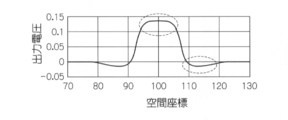
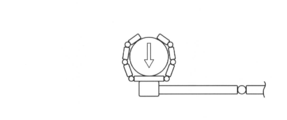
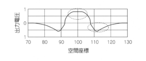
Classifications
-
- H—ELECTRICITY
- H04—ELECTRIC COMMUNICATION TECHNIQUE
- H04N—PICTORIAL COMMUNICATION, e.g. TELEVISION
- H04N25/00—Circuitry of solid-state image sensors [SSIS]; Control thereof
Definitions
- the present invention relates to a spatio-temporal data processing apparatus and program, and more particularly, to a spatio-temporal data processing apparatus and program that outputs a voltage distribution from a current distribution according to an input stimulus, and a current characteristic according to the input stimulus.
- the present invention relates to a spatiotemporal data processing apparatus and program for outputting a voltage information distribution from an information distribution.
- sensors and sensor systems that analyze an event that stimulates a sensor by integrating information of a plurality of spatially distributed sensor elements are widely used in the industry.
- an image sensor including an array of unit active pixels and an image sensor including an active pixel array are known (Patent Documents 1 and 2).
- Patent Documents 1 and 2 an image sensor including an array of unit active pixels and an image sensor including an active pixel array are known (Patent Documents 1 and 2).
- a CCD image sensor and a CMOS image sensor are typical, and visual information can be captured as a two-dimensional image by adding a lens system.
- CCD image sensors and CMOS image sensors not only respond linearly to the intensity of the stimulus, but also have little time delay and respond quickly when a stimulus is applied.
- JP 2007-20194 A JP 2007-19521 A
- the present invention has been made to solve the above-described problems, and is a spatio-temporal data processing apparatus capable of outputting a voltage distribution or a voltage information distribution that emphasizes an input stimulus distribution by simple processing. And to provide a program.
- the spatio-temporal data processing device comprises a current that changes in response to a stimulus input to each of array positions arranged in one or more dimensions.
- current conversion means for outputting a plurality of current distributions weighted for each current distribution and a plurality of spatial filters described by a lossy diffusion equation and having different filter characteristics.
- Filter conversion means for converting the plurality of current distributions output by the current conversion means into a plurality of voltage distributions composed of voltages for respective arrangement positions; and the plurality of voltage distributions converted by the filter conversion means.
- adding means for adding at each arrangement position and outputting the voltage distribution obtained by the addition.
- a program for the current distribution comprising a current that changes in response to a stimulus input to each of array positions arranged in one or more dimensions.
- Current conversion means for outputting a plurality of current distributions weighted for each distribution, each of the plurality of spatial filters described by a lossy diffusion equation and having different filter characteristics is output by the current conversion means.
- Filter conversion means for converting the plurality of current distributions into a plurality of voltage distributions composed of voltages for each arrangement position, and adding the plurality of voltage distributions converted by the filter conversion means for each arrangement position, This is a program for functioning as addition means for outputting the voltage distribution obtained by addition.
- the current converter comprises a current distribution composed of a current that changes in response to a stimulus input to each of the array positions arranged in one or more dimensions. And outputting a plurality of current distributions weighted for each current distribution.
- the plurality of current distributions output by the current conversion means are obtained for each array position by using each of a plurality of spatial filters described by a loss diffusion equation and having different filter characteristics by the filter conversion means. Convert to multiple voltage distributions of voltage.
- the adding means adds the plurality of voltage distributions converted by the filter converting means for each arrangement position, and outputs the voltage distribution obtained by the addition.
- a voltage distribution emphasizing the input stimulus distribution can be output.
- a spatio-temporal data processing device is a current conversion means for outputting a current distribution comprising a current that changes in response to a stimulus input to each of array positions arranged in one or more dimensions.
- the current distribution output by the current conversion means using each of a plurality of spatial filters described by a lossy diffusion equation and having different filter characteristics, and a plurality of voltage distributions composed of voltages corresponding to respective array positions.
- Filter conversion means for converting into the voltage distribution, and for the plurality of voltage distributions converted by the filter conversion means, the voltage distribution is weighted for each voltage distribution and added for each array position, and the voltage distribution obtained by the addition And adding means for outputting.
- a program for a computer having an array position arranged in one or more dimensions using each of a plurality of spatial filters described by a lossy diffusion equation and having different filter characteristics.
- Current conversion means for outputting a current distribution comprising currents that change in response to stimuli input to each of the current conversion means, and converting the current distribution output by the current conversion means into a plurality of voltage distributions comprising voltages for each array position.
- Filter conversion means, and the plurality of voltage distributions converted by the filter conversion means are weighted for each voltage distribution and added for each array position, and the voltage distribution obtained by the addition is output. It is a program for functioning as an adding means.
- the current conversion means outputs a current distribution comprising currents that change in accordance with the stimulus input to each of the array positions arranged in one or more dimensions.
- a plurality of spatial filters described by a loss diffusion equation by the filter conversion means and having different filter characteristics are used to convert the current distribution output by the current conversion means to a plurality of voltages corresponding to the arrangement positions. To the voltage distribution.
- the adding means weights the plurality of voltage distributions converted by the filter converting means for each voltage distribution, adds them for each array position, and outputs the voltage distribution obtained by the addition.
- a voltage distribution emphasizing the input stimulus distribution can be output.
- the current conversion means according to the third invention outputs a plurality of current distributions weighted for each current distribution with respect to the current distribution, and the filter conversion means uses each of the plurality of spatial filters to convert the current conversion means. Can be converted into a plurality of voltage distributions.
- the current conversion means outputs a plurality of current distributions weighted for each current distribution based on the current distribution and the current at each array position modulated by pulse width modulation or pulse density modulation. Can do.
- the current conversion means according to the third invention can output a current distribution obtained by modulating the current at each array position of the current distribution by pulse width modulation or pulse density modulation.
- Each of the spatial filters according to the first aspect of the present invention includes a plurality of resistance elements provided so as to connect between outputs of currents at adjacent arrangement positions in a corresponding current distribution output by the current conversion unit, It can be configured to include a plurality of parallel circuits in which one end is connected to the output of the current at each array position and the other end is grounded, and the resistance element and the capacitance element are connected in parallel. .
- Each of the spatial filters according to the third aspect of the present invention includes a plurality of resistance elements provided so as to connect the outputs of currents at adjacent arrangement positions in the current distribution output by the current conversion means, and one end of each of the resistance elements. It can be configured to include a plurality of parallel circuits in which a resistor element and a capacitor element are connected in parallel, which are provided so as to connect outputs of currents at respective arrangement positions and to ground each other end.
- the time constant of the parallel circuit provided in each of the above spatial filters can be configured to be different from that of other spatial filters.
- the spatial filter can be configured so that the filter characteristics are different.
- the spatial filter can be configured so that the filter characteristics are different.
- the resistance element of the parallel circuit described above may have an inductive component. Further, the capacitance of the capacitive element of the parallel circuit may be zero.
- the plurality of spatial filters according to the first invention are two spatial filters, wherein the current conversion means outputs a current distribution subjected to positive weighting and a current distribution subjected to negative weighting,
- the filter conversion means can convert the two current distributions output by the current conversion means into two voltage distributions using each of the two spatial filters.
- the plurality of spatial filters according to the third invention are two spatial filters, and the filter conversion means uses each of the two spatial filters to convert the current distribution output by the current conversion means into two voltage distributions.
- the adding means performs positive weighting on one of the two voltage distributions converted by the filter converting means, negative weighting on the other, and adds and adds each array position. The voltage distribution obtained in this way can be output.
- the spatio-temporal data processing device is a second method for converting each of the plurality of voltage distributions converted by the filter conversion means, using each of a plurality of second spatial filters different from the plurality of spatial filters. Further including filter conversion means, the addition means can add the plurality of voltage distributions converted by the second filter conversion means for each arrangement position, and output the voltage distribution obtained by the addition.
- a spatio-temporal data processing device is a second method for converting each of a plurality of voltage distributions converted by the filter conversion means, using each of a plurality of second spatial filters different from the plurality of spatial filters.
- the voltage conversion unit further includes a filter conversion unit, and the addition unit weights the voltage distributions converted by the second filter conversion unit for each voltage distribution, adds the voltage distributions for each array position, and adds the voltage distributions. Can be output.
- the filter characteristics of the plurality of spatial filters can be changed according to a desired voltage distribution. Thereby, a desired voltage distribution can be output.
- the above spatial filter can be described by an equation in which a second-order differential term with respect to time is added to a lossy diffusion equation.
- the spatio-temporal data processing apparatus may further include a shutter that is provided before the input position to the spatial filter and that can shut off an input stimulus or current distribution and can switch whether or not to shut it off. it can.
- the above spatio-temporal data processing device may further include a filter processing unit that performs a filtering process for each arrangement position on the voltage distribution output by the adding unit.
- the above filter processing means can lower the gain of the filter processing for the array positions around the array position, as the output obtained by the filter processing is larger for each array position.
- a spatio-temporal data processing device relates to a current information distribution comprising current information that changes in response to a stimulus input to each of array positions arranged in one or more dimensions.
- a current information converting means for outputting a plurality of current information distributions weighted for each current information distribution, and a plurality of spatial filters described by lossy diffusion equations and having different filter characteristics.
- the filter conversion means for converting the plurality of current information distributions output by the current information conversion means into a plurality of voltage information distributions composed of voltage information for each array position; and the filter conversion means And adding means for adding the plurality of converted voltage information distributions for each array position and outputting the voltage information distribution obtained by the addition.
- a program for current information distribution including current information that changes in response to a stimulus input to each of array positions arranged in one or more dimensions.
- Current information conversion means for outputting a plurality of current information distributions weighted for each current information distribution, each of the plurality of spatial filters described by a lossy diffusion equation and having different filter characteristics
- Filter conversion means for converting the plurality of current information distributions output by the current information conversion means into a plurality of voltage information distributions composed of voltage information for each array position; and the filter conversion means Further, the plurality of voltage information distributions are added for each arrangement position, and function as addition means for outputting the voltage information distribution obtained by the addition.
- the current information conversion means comprises current information that changes in response to a stimulus input to each of the array positions arranged in one or more dimensions.
- a plurality of current information distributions weighted for each current information distribution are output.
- the adding means adds the plurality of voltage information distributions converted by the filter conversion means for each arrangement position, and outputs the voltage information distribution obtained by the addition.
- the current information is information related to the flow
- the voltage information is information related to the measurement.
- Examples of pairs of current information and voltage information include heat quantity and temperature, carrier and potential, processing information and detection information.
- the spatio-temporal data processing device outputs a current information distribution comprising current information that changes in response to a stimulus input to each of array positions arranged in one or more dimensions.
- a current information distribution comprising current information that changes in response to a stimulus input to each of array positions arranged in one or more dimensions.
- the current information distribution output by the current information conversion means Filter conversion means for converting into a plurality of voltage information distributions consisting of voltage information with respect to the array position, and weighting for each of the voltage information distributions with respect to the plurality of voltage information distributions converted by the filter conversion means
- adding means for adding each of the arrangement positions and outputting a voltage information distribution obtained by the addition.
- a program for outputting a current information distribution comprising current information that changes in response to a stimulus input to each of array positions arranged in one or more dimensions.
- Filter conversion means for converting into a plurality of voltage-like information distributions consisting of voltage-related information, and weighting each of the voltage information distributions with respect to the plurality of voltage-like information distributions converted by the filter conversion means This is a program for adding to each arrangement position and functioning as an adding means for outputting the voltage information distribution obtained by the addition.
- the current information conversion means comprises current information that changes according to a stimulus input to each of the array positions arranged in one or more dimensions. Output current information distribution.
- the current information distribution output by the current information conversion means is obtained for each array position. It is converted into a plurality of voltage information distributions consisting of voltage information.
- an image (emphasized image) that is characteristic of human vision can be obtained as a voltage distribution by the configuration of the present invention.
- a contour-enhanced image and a moving object-enhanced image can be obtained as the output voltage distribution. Since the present invention can obtain in real time an emphasized image that humans feel characteristically, if it is used for an in-vehicle camera or a security camera, the danger can be detected quickly. Since it can be configured with a relatively simple circuit, it may be realized as a hardware circuit, or may be realized as software if the calculation speed is fast.
- the sensor device 10 is configured using a plurality of light receiving elements arranged in a one-dimensional manner and outputs input light from the plurality of light receiving elements.
- a current converter 14 that outputs a positively weighted current distribution and a negatively weighted current distribution by converting the current distribution into a current distribution representing a current to be output and weighting the current distribution, and a positive weight
- the converted current distribution is converted by using the first spatiotemporal filter to convert the current distribution into a voltage distribution, and the negatively weighted detection signal distribution
- a space-time filter unit 16B that converts to a voltage distribution by performing a conversion process using a second space-time filter having a filter characteristic different from that of the first space-time filter, and a space-time filter Data portion 16A, and an adder 18 for generating and outputting the enhanced data by adding the converted voltage distribution by 16B.
- the sensor device 10 corresponds to the spatiotemporal data processing device of the present invention.
- the current conversion unit 14 is configured by using a plurality of light receiving elements arranged one-dimensionally. Each light receiving element outputs a current corresponding to light received as a stimulus, and a current corresponding to each array position of the light receiving elements. A current distribution consisting of In addition, the current conversion unit 14 applies a positive weight to the generated current distribution, and converts the pulse current distribution of the same sign, which has been modulated by pulse density modulation or pulse width modulation, to a spatiotemporal filter unit The pulse current distribution of the inverted code subjected to negative weighting (inverted sign) and modulated by pulse density modulation or pulse width modulation is output to the space time filter unit 16B.
- the spatio-temporal filter unit 16A uses the first spatio-temporal filter described by the lossy diffusion equation to convert the pulse current distribution having the same sign as the current distribution into a voltage distribution composed of voltages for the respective array positions. The result is output to the adding unit 18.
- the spatio-temporal filter unit 16B uses a second spatio-temporal filter that is described by a lossy diffusion equation and has a filter characteristic different from that of the first spatial filter.
- the voltage is converted into a voltage distribution made up of voltages with respect to the array positions and output to the adder 18.
- the adding unit 18 generates and outputs enhanced data that emphasizes the detection target as an overall image of the stimulus by adding each of the voltage distributions output from the space-time filter units 16A and 16B for each arrangement position. .
- the current conversion unit 14 is a current having the same sign as the current from the light receiving element at the corresponding array position, and from the light receiving element.
- a plurality of constant current sources 20A that output a pulse current modulated by pulse density modulation or pulse width modulation, and a current of an inverted sign with respect to the current from the light receiving element at the corresponding array position, This is realized by a plurality of constant current sources 20B that output a pulse current modulated by pulse density modulation or pulse width modulation.
- the constant current sources 20A and 20B are provided corresponding to the respective light receiving elements.
- the spatio-temporal filter units 16A and 16B include a plurality of resistance elements 22A provided so as to connect the outputs of the constant current sources 20A corresponding to the adjacent arrangement positions, and the constant current sources corresponding to the adjacent arrangement positions.
- a plurality of resistance elements 22B provided so as to connect between the outputs of 20B, and one end connected to the output of the constant current source 20A at the corresponding array position, and the other end provided to be grounded
- This is realized by a plurality of parallel circuits 28B in which the element 24B and the capacitive element 26B are connected in parallel.
- the adder 18 adds a voltage output from one end of the parallel circuit 28A at the corresponding array position and a voltage output from one end of the parallel circuit 28B at the corresponding array position, and outputs a plurality of adders 30. It is realized with.
- Q 0ave, on is the current showing the time average of the pulse current output from the constant current source 20A corresponding to x0 point indicating the sequence position (charge)
- C on is an capacitance of the capacitor 26A
- ⁇ d, on are time constants (see FIG. 3) relating to diffusion determined by multiplication of the capacitance C on and the resistance value R on of the resistance element 22A
- ⁇ c, on are the capacitance C on and the resistance element 24A.
- it is a time constant (see FIG. 3) of the Radiated determined by the ratio between the leakage conductance G on.
- the above equation (1) represents the conversion from current to voltage using the first space-time filter described by the lossy diffusion equation.
- Q 0ave, off is a current (charge) indicating the time average of the pulse current output from the constant current source 20B corresponding to the point x0 indicating the arrangement position
- C off is the capacitance of the capacitive element 26B.
- ⁇ d, off are time constants concerning diffusion determined by multiplication of the capacitance C off and the resistance value R off of the resistance element 22B
- ⁇ c, off are the leakage conductance G off of the capacitance C off and the resistance element 24B. It is a time constant related to leakage determined by the ratio of.
- the above equation (2) represents the conversion from current to voltage using the second spatio-temporal filter described by the lossy diffusion equation.
- a voltage (differential potential) Dfv (x) obtained by adding the voltages output from one end of the parallel circuits 28A and 28B corresponding to the point x indicating the arrangement position is expressed by the following equation (3).
- the differential transimpedance can be defined by the above equation (5).
- DTI (x) is determined to be 0 at a finite distance xc and an infinite distance.
- the range of parameter b is determined as in the following equation (8).
- Dfv (x) is expressed by the following equation (9) according to the above equations (7) and (8).
- the time constant ⁇ c, on of the parallel circuit 28A and the time constant ⁇ c, off of the parallel circuit 28B are different, and the resistance value R on of the resistance element 22A and the resistance value R off of the resistance element 22B are Therefore, the first spatiotemporal filter of the spatiotemporal filter unit 16A and the second spatiotemporal filter of the spatiotemporal filter unit 16B have different filter characteristics.
- the resistive element 24A of the parallel circuit 28A and the resistive element 24B of the parallel circuit 28B may have an inductive component.
- the capacitance of the capacitive element 26A of the parallel circuit 28A or the capacitance of the capacitive element 26B of the parallel circuit 28B may be zero.
- first spatiotemporal filter of the spatiotemporal filter unit 16A and the second spatiotemporal filter of the spatiotemporal filter unit 16B include desired enhancement data (for example, data in which the contour of the detection target is enhanced, stimulus intensity) Data that automatically decreases in sensitivity to increase, data that responds faster as the intensity of the stimulus increases, data whose contrast changes according to the moving direction (motion vector) of the detection target, etc. It is configured to be changeable. That is, the resistance values, capacitances, and leakage conductances of the parallel circuits 28A and 28B that implement the space-time filter units 16A and 16B and the resistance values of the resistance elements 22A and 22B are variably configured.
- desired enhancement data for example, data in which the contour of the detection target is enhanced, stimulus intensity
- desired enhancement data for example, data in which the contour of the detection target is enhanced, stimulus intensity
- various parameters (x c , k on , k Q , b, R on , ⁇ d, on , k d ) are set by an operator according to desired enhancement data, and the first and second space-time filters are set.
- the resistive elements 22A and 22B and the parallel circuits 28A and 28B are configured by the resistive elements 22A and 22B and the parallel circuits 28A and 28B so that the filter characteristics correspond to the various parameters set.
- the current output from the light receiving element at the corresponding array position is input to each of the constant current sources 20A and 20B, and the constant current source 20A has a current having the same sign as the input current.
- a pulse current modulated by pulse density modulation is output.
- the constant current source 20B outputs a pulse current that has an inverted sign with respect to the input current and is modulated by pulse density modulation.
- the voltage is converted into a voltage distribution by the plurality of parallel circuits 28A and the plurality of resistance elements 22A that realize the space-time filter unit 16A.
- the voltage distribution is converted into the voltage distribution by the plurality of parallel circuits 28B and the plurality of resistance elements 22B that realize the space-time filter unit 16B.
- the adder 30 that realizes the adder 18 adds the voltage for each arrangement position to the voltage distribution output from the space-time filter units 16A and 16B, and generates enhanced data that emphasizes the detection target. Output.
- the information processing by the program that causes the computer to function as each of the weighting unit 14, the space-time filter units 16A and 16B, and the adding unit 18 is a conversion processing routine shown in the flowchart of FIG. Can be realized.
- the computer includes a CPU, a ROM, and a RAM connected to each other by a bus, and an HDD connected as necessary. These programs are recorded on a recording medium such as a ROM or an HDD connected to the CPU of the computer. To be recorded.
- step 100 current distributions output from a plurality of light receiving elements are acquired.
- step 102 the current distribution acquired in step 100 is modulated by pulse density modulation with the same sign.
- a pulse current distribution is generated, and in step 104, a pulse current distribution modulated by pulse density modulation with an inversion code is generated from the current distribution acquired in step 100.
- step 106 the pulse current distribution having the same sign as the current distribution generated in step 102 is converted into a voltage distribution using the first space-time filter.
- step 108 the pulse current distribution is generated in step 104.
- the current distribution and the pulse current distribution having the inverted sign are converted into a voltage distribution using the second space-time filter.
- step 110 the emphasis data is generated and output by adding the voltage distribution obtained in step 106 and the voltage distribution obtained in step 108, and the process returns to step 100.
- the pulse current distribution modulated with the same sign as the current distribution from the light receiving element and the pulse current distribution modulated with the inversion code are represented by filter characteristics. Are converted into two voltage distributions using two different spatio-temporal filters, and the two converted voltage distributions are added to output emphasized data in which the input stimulus distribution is emphasized by simple processing. be able to.
- the processing of acquired information is performed non-linearly and quickly without data processing by software. Can be processed.
- the enhancement data in which the boundary portion of the whole image of the stimulus is automatically emphasized is output, it becomes possible to grasp the whole image of the stimulus by the enhancement data.
- emphasizing data that automatically decreases in sensitivity to an increase in the intensity of the stimulus is output, protection that automatically suppresses the stimulus against an excessive stimulus is activated, and sensor sensitivity with a wide dynamic range is achieved. Can be realized.
- in the case of outputting emphasized data in which the reaction time becomes faster as the intensity of the stimulus is larger it becomes possible to detect a stimulus with a large change at a higher speed by the enhanced data.
- the enhancement data whose contrast changes with respect to the moving direction of the stimulus is output, the moving direction of the stimulus can be instantaneously estimated from the contrast of the enhanced data.
- the second embodiment is different from the first embodiment in that weighted addition is performed on the voltage distribution output from the spatiotemporal filter unit.
- the sensor device 210 is configured to apply pulse width modulation or pulse density modulation to each of currents representing currents output from a plurality of light receiving elements.
- the current conversion unit 214 that outputs the modulated pulse current distribution modulated by the above and the pulse current distribution output from the current conversion unit 214 is converted using the first space-time filter
- the space time filter unit 16A that converts the voltage distribution into the voltage distribution and the pulse current distribution output from the current conversion unit 214 is converted into the voltage distribution by performing conversion processing.
- the space time filter unit 16B and the voltage distribution converted by the space time filter unit 16A are weighted positively and converted by the space time filter unit 16B. It performs negative weighted voltage distributions, and a weighted addition unit 218 for generating and outputting the enhanced data by adding each of the weighted voltage distribution.
- the weighting addition unit 218 performs positive weighting on the voltage distribution converted by the space-time filter unit 16A, negative weighting on the voltage distribution converted by the space-time filter unit 16B, and also for each array position. By adding the voltage to each of the weighted voltage distributions, emphasis data emphasizing the detection target as the entire image of the stimulus is generated and output.
- the current converter 214 is realized by a plurality of constant current sources (not shown) that output a pulse current modulated by pulse density modulation or pulse width modulation with respect to the current from the light receiving elements at the corresponding array positions.
- the weighted addition unit 218 outputs a plurality of same-sign output circuits (not shown) that output the voltage output from one end of the parallel circuit 28A at the corresponding array position with the same sign, and one end of the parallel circuit 28B at the corresponding array position.
- a plurality of inversion code output circuits (not shown) that output the output voltage with an inversion sign, and a plurality of additions that are output by adding the output of the corresponding same sign output circuit and the output of the corresponding inversion code output circuit This is realized by the device 30.
- various parameters are set, and the spatial time realized by the resistive elements 22A and 22B and the parallel circuits 28A and 28B so that the first and second spatio-temporal filters have filter characteristics according to the set various parameters.
- the filter units 16A and 16B are configured.
- a current corresponding to the incident light is output from each light receiving element, and a current distribution is generated.
- the current output from the light receiving element at the corresponding array position is input to the constant current source, and the pulse current modulated by the pulse density modulation is output by the constant current source.
- the voltage is converted into a voltage distribution by the plurality of parallel circuits 28A and the plurality of resistance elements 22A that implement the space-time filter unit 16A. Further, based on the distribution of the pulse current output from the constant current source for each array position, the voltage distribution is converted into the voltage distribution by the plurality of parallel circuits 28B and the plurality of resistance elements 22B that implement the space-time filter unit 16B.
- the voltage distribution output from the space-time filter unit 16A is output with the same sign by the same sign output unit that implements the weighted addition unit 218, and the voltage distribution output from the space-time filter unit 16B by the inverted code output unit Is output with the inverted sign.
- the adder 30 that implements the weighted addition unit 218 applies a voltage for each arrangement position to the voltage distribution composed of the outputs of the plurality of same sign output units and the voltage distribution composed of the outputs of the plurality of inverted sign output units. Addition is performed to generate and output enhanced data that emphasizes the detection target.
- information processing by a program that causes a computer to function as each of the current conversion unit 214, the spatio-temporal filter units 16A and 16B, and the weighted addition unit 218 is a conversion processing routine described below. Can be realized.
- one of the obtained voltage distributions is output as a voltage distribution with the same sign, and the other voltage distribution is output as a voltage distribution with an inverted sign.
- the emphasis data is generated and output by adding the obtained voltage distribution of the same sign and the voltage distribution of the inverted sign, and the process returns to the first process.
- the pulse current distribution modulated from the current distribution from the light receiving element is converted into two voltage distributions using two space-time filters having different filter characteristics, and the two converted voltage distributions are weighted and added.
- the input stimulus distribution is emphasized by a simple process.
- the current distribution may be further weighted and modulated by pulse density modulation or pulse width modulation.
- pulse current distributions having different weights are output to the spatiotemporal filter units 16A and 16B.
- the distribution of current for each array position is output by light receiving elements arrayed two-dimensionally, and the current distribution distributed two-dimensionally by a spatiotemporal filter is converted into a voltage distribution. This is mainly different from the first embodiment.
- the spatiotemporal filter unit 16A is provided with a plurality of parallel circuits 28A corresponding to each of the two-dimensional array positions, and the spatiotemporal filter unit 16B includes a plurality of parallel circuits. 28B is provided corresponding to each of the two-dimensional array positions.
- the obtained current and voltage are distributed in two dimensions, and the response of DTI (x) takes into account the pixel size of the current output by the light receiving element, and is sharper in the vicinity of the pixel than the response of the Laplacian Gaussian filter. It has become.
- enhancement data smoothly representing the detection target is obtained (elapsed time 0.3 seconds)
- FIG. 13 and 14 the enhancement data in which the center portion of the detection target is emphasized is obtained (elapsed time 2.3 seconds), and the contour of the detection target, particularly the detection target, is obtained as shown in FIGS.
- the emphasis data in which the apex portion of the image is emphasized was obtained (elapsed time 40 seconds, 51 seconds).
- the pulse current distribution modulated with the same sign and the pulse current distribution modulated with the inverted code are divided into two spatiotemporal filters having different filter characteristics. Is converted into two voltage distributions, and the two converted voltage distributions are added to each other, so that the emphasized data in which the input stimulus distribution is emphasized can be output by a simple process.
- the processing of acquired information is processed nonlinearly and at high speed without data processing by software. be able to.
- the sensor device may be realized by a program for causing a computer to function as each unit of the sensor device. .
- the current (pulse current) corresponding to the input stimulus is blocked at a position before the input point of the spatio-temporal filter units 16A and 16B, and whether to block is switched.
- a possible shutter may be provided. Thereby, emphasized data of the center part of the detection target as shown in FIG. 12 can be obtained as necessary. Moreover, you may make it provide the shutter which can interrupt
- the present invention is applied to the sensor device.
- the present invention is not limited to this, and the present invention is applied to a high-function camera. May be applied.
- a high-function camera that can automatically correct the local sensitivity according to the input intensity, extract motions, extract contours from low signal-to-noise ratio images, or extract targets that change in the same direction or cycle. can do.
- the current conversion unit includes a light receiving element
- the present invention is not limited to this, and image data including a plurality of pixel values output by the imaging device is converted into current as a stimulus. You may be comprised so that it may input into a part.
- the current conversion unit may output a pulse current distribution including a pulse current corresponding to each pixel value.
- the fourth embodiment is different from the first embodiment in that a current converter provided with a plurality of sensor elements that detect input stimuli is used.
- the current conversion unit 14 of the sensor device is arranged in a one-dimensional manner and detects a plurality of stimuli other than the input light (for example, heat, sound, smell, touch stimulus, etc.).
- a sensor element is used, and each sensor element outputs a detection signal corresponding to the input stimulus.
- the current conversion unit 14 performs positive weighting and negative weighting on the detection signals corresponding to the respective array positions of the sensor elements, and the pulse current corresponding to the detection signals of the same sign subjected to the positive weighting.
- the pulse current distribution is output after being converted into a pulse current, and the pulse current distribution is output after being converted into a pulse current corresponding to the detection signal of the inverted sign subjected to negative weighting.
- the addition unit 18 generates and outputs enhancement data that emphasizes the entire image of the stimulus by adding each of the voltage distributions output from the space-time filter units 16A and 16B for each arrangement position.
- the pulse current distribution modulated from the detection signal of the same sign and the pulse current distribution modulated from the detection signal of the inverted sign with respect to the detection signal from the sensor element are converted into two spatio-temporal filters having different filter characteristics.
- the sensor device may be realized by a program for causing a computer to function as each unit of the sensor device. .
- the fifth embodiment is different from the first embodiment in that the spatio-temporal filter unit and the addition unit are realized by a calculation using one mathematical expression.
- an operation using one mathematical expression equivalent to the processing of the spatiotemporal filter units 16A and 16B and the addition unit 18 is performed by a computer.
- one mathematical expression equivalent to the processing of the space-time filter units 16A and 16B and the addition unit 18 will be described.
- the voltage distribution V off obtained by converting the negative weighted current distribution by the space time filter unit 16B is used as a reference, and the voltage distribution V on obtained by converting the positive weighted current distribution by the space time filter unit 16A is used as a reference.
- the following equation (10) is obtained.
- G off is a value corresponding to the leakage conductance of the resistance element 24B
- R off is a value corresponding to the resistance value R off of the resistance element 22B.
- V is a value corresponding to the output voltage of the space time filter units 16A and 16B
- x is a point indicating the arrangement position
- Q 0ave is a current (charge) indicating the time average of the pulse current output from the constant current source corresponding to the point x0 indicating the arrangement position.
- the parameters R off and G off of the Off network can be expressed by the equations (13) and (14), respectively, with the On network parameters as references. Therefore, it is possible to obtain a formula for calculating the differential voltage Dfv (x) with good visibility using the difference parameters ⁇ R and ⁇ G of the off circuit network and the on circuit network and the parameters of the On circuit network.
- the distribution of the pulse current generated by the current conversion unit 14 and modulated by the pulse density modulation with the same sign is input, and the spatiotemporal filter units 16A and 16B, and the addition unit
- the calculation using the above equation (15) equivalent to the processing of 18 is performed, the voltage is calculated for each array position x, and the emphasis data that is the voltage distribution is output.
- the current distribution output from the plurality of light receiving elements is acquired, and the distribution of the pulse current modulated by pulse density modulation with the same sign is obtained from the acquired current distribution. Generate.
- the enhancement data is approximated according to the approximate expression based on the difference of the filter characteristics of the space-time filter that approximates the processing of the space-time filter unit and the addition unit. Can be generated. Moreover, since it is realized by the calculation of one mathematical expression, it can be processed at high speed.
- the case where the emphasis data is output by the calculation of the mathematical expression approximated using the first-order term has been described as an example.
- the present invention is not limited to this, and the second-order or higher term is used.
- Emphasis data may be output by calculation of a mathematical expression approximated using. Any other approximate expression may be used as long as the output is equivalent.
- the sixth embodiment is different from the first embodiment in that a filtering process is further performed on the voltage distribution output by the adding unit.
- the sensor device 610 includes a current distribution unit 14, space-time filter units 16 ⁇ / b> A and 16 ⁇ / b> B, an addition unit 18, and a voltage distribution output by the addition unit 18.
- an output filter unit 618 that performs filter processing is provided.
- the output filter unit 618 performs a filtering process for each arrangement position on the voltage distribution as the enhanced data output from the adding unit 18 and outputs the enhanced data subjected to the filtering process.
- the output filter unit 618 performs non-linear processing such as a filter that performs half-wave rectification, a filter that performs full-wave rectification, a filter that outputs absolute voltage, and a filter that outputs effective voltage (instantaneous output or time moving average). Filter processing is performed for each array position using the filter to be performed. In addition, you may make it perform a filter process for every arrangement
- the current conversion unit 14 performs pulse density modulation using a current pulse with a pulse width of 30 ⁇ s
- the space time filter units 16A and 16B and the addition unit 18 calculate differential voltages
- the output filter unit 618 calculates the effective voltage.
- the output filter unit 618 calculates the effective voltage.
- the current conversion unit 14 performs pulse width modulation using a current pulse with a duty ratio of 50%
- the differential voltage is calculated by the spatiotemporal filter units 16A and 16B and the addition unit 18, and the output filter unit 618
- the output filter unit 618 In the case of outputting an effective voltage, when a stimulus having a frequency of 10 to 3000 Hz is applied to one point and the output voltage at the corresponding array position is measured, a differential voltage corresponding to the frequency of the current pulse as shown in FIG. Is obtained. Since the sensitivity with respect to a specific frequency (for example, 100 Hz) becomes high, an output closer to a human sense can be obtained.
- the seventh embodiment is different from the sixth embodiment in that the voltage distribution output by the adder is further filtered using a spatial filter.
- the gain of the filter process for the array positions around the array position is decreased. Adjust to.
- the output filter unit 618 includes a plurality of filter processing units 720 provided corresponding to the plurality of adders 30, as shown in FIG.
- the filter processing unit 720 receives the output of the corresponding adder 30 and the output of the adjacent filter processing unit 720, feeds back the output of the adjacent filter processing unit 720, adjusts the gain, and adds the adder 30. Filtering is performed on the output from. In the present embodiment, the gain of the surrounding filter processing units is lowered as the output of the filter processing units is increased by adjusting the gain.
- the sensor device acts to lower the sensitivity after once increasing the surrounding sensitivity at the arrangement position where the stimulus is applied. That is, when the vicinity is stimulated, the initial sensitivity is increased, and a hypersensitive state is realized. Moreover, in steady stimulation, it acts on the direction which lowers a sensitivity mutually, and suppresses surrounding sensitivity.
- the output filter unit described in the sixth embodiment and the output filter unit described in the seventh embodiment may be used in combination.
- the case where the voltage distribution of the emphasized data to be output is one-dimensional has been described as an example.
- the present invention is not limited to this, and the present invention is applied when a voltage distribution of two or more dimensions is output. May be.
- the filtering process may be performed using a spatial filter corresponding to a two-dimensional or higher array position.
- the filter processing unit 720 has been described as an example in which the output of the adjacent filter processing unit is fed back, but is not limited thereto, and the filter processing unit 720 includes the output of the corresponding adder 30,
- the output of the peripheral filter processing unit 720 may be input, the output of the peripheral filter processing unit 720 may be fed back to adjust the gain, and the filter processing may be performed on the output from the adder 30. .
- a robot apparatus 810 includes a robot hand 812, a control sensor apparatus 813 for feedforward control of the robot hand 812 with the sensor output from the robot hand 812 as an input, An image sensor 814 that images the robot hand 812, detects the position of the robot hand 812, and outputs position information of each part of the robot hand 812, and an image sensor device 815 that receives the sensor output from the image sensor 814 as input. And a feedback control unit 816 that performs feedback control based on outputs from the control sensor device 813 and the image sensor device 815.
- the robot hand 812 includes a plurality of joint portions 820, a plurality of finger portions 822 connected via the joint portions 820, and a palm portion connected to the finger portions 822 via the joint portions 820.
- a distributed stress sensor 826 that is provided on the upper side so as to cover the finger part 822 and the palm part 824, detects a distribution of stress acting on the finger part 822 and the palm part 824, and a robot that supports the palm part 824 Arm 828.
- the robot hand 812 is an actuator group including a plurality of actuators that are provided at a plurality of joint portions 820 and a joint portion 830 provided at the robot arm 828 to drive the joints to bend and extend. 832.
- the distributed stress sensor 826 a conventionally known sensor that detects the distribution of the acting stress may be used.
- control sensor device 813 and the image sensor device 815 have the same configuration as the sensor device 10 including the plurality of spatiotemporal filter units 16A and 16B described in the first embodiment. Is omitted.
- the control sensor device 813 receives data indicating the stress distribution for each position (arrangement position) of the finger part 822 and palm part 824, which is output from the distributed stress sensor 826, and inputs each data of the finger part 822 and palm part 824.
- Output data (emphasis data) corresponding to the mechanical force applied to the position (array position) is output to the actuator group 832 (feed forward control).
- the driving force in the direction of bending the joint increases as the value of the data input from the control sensor device 813 increases.
- the actuator provided in the joint portion 830 of the robot arm 828 has a driving force in a direction in which the position of the palm portion 824 is raised higher as the value of the data input from the control sensor device 813 increases. growing.
- the image sensor 814 captures an image of the robot hand 812, performs image recognition processing, detects the positions of the finger part 822 and palm part 824 of the robot hand 812, and obtains position information of each part of the finger part 822 and palm part 824. Calculate.
- the image sensor device 815 receives data indicating position information of each position (array position) of the finger part 822 and the palm part 824, which is output from the image sensor 814, and inputs each position of the finger part 822 and the palm part 824 ( Output data (emphasis data) with respect to (array position) is output to the feedback control unit 816.
- the feedback control unit 816 outputs stress output data (emphasis data) for each array position output from the control sensor device 813 and output data (emphasis data) for each array position output from the image sensor device 815. Based on this, feedback control is performed. That is, output data of each position (arranged position) of the finger part 822 and the palm part 824 based on feedback control is output to the actuator group 832, and the actuator corresponding to each position of the finger part 822 and the palm part 824 is output. , Input the corresponding control data.
- the stress applied to each position of the finger part 822 and the palm part 824 is detected by the distributed stress sensor 826, and the position information of each position of the finger part 822 and the palm part 824 is detected by the image sensor 814.
- the control sensor device 813 generates emphasis data based on the data of each position output from the distributed stress sensor 826, and outputs a feedforward control signal to the actuator group 832 and also outputs it to the feedback control unit 816. To do.
- the actuator group 832 of the robot hand 812 drives the joint portions 820 and 830 according to the input data.
- the image sensor device 815 generates enhancement data based on the position information of each position output from the image sensor 814, and outputs it to the feedback control unit 816.
- the feedback control unit 816 performs feedback control of the actuator group 832 based on the enhancement data from the control sensor device 813 and the enhancement data from the image sensor device 815.
- the joint portions 820 and 830 are driven according to feedback control.
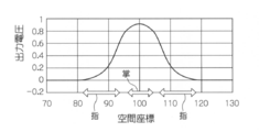
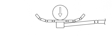
- the control sensor device 813 when the object collides with the palm part 824, the control sensor device 813 outputs emphasized data for each position of the finger part 822 and the palm part 824 as shown in FIG. 22B.
- a control force corresponding to a mechanical force in the direction of extending the finger portion 822 and lowering the palm portion 824 is generated by the actuator group 832 and the joint portions 820 and 830 are driven.
- a powerful control force in a direction to rapidly reduce the height of the palm 824 is created so as to absorb the impact caused by the collision of the object (the acceleration is specified by the control force. Does not move the palm position).
- the control sensor device 813 reduces the output of the palm 824 as shown in FIG. 23B, and the output of the finger 822 around the palm 824 decreases.
- the emphasized data is output (the value of the polarity for closing the joint of the finger 822 is output).
- the actuator group 832 drives the joint portions 820 and 830 so as to bend the joint of the finger portion 822.
- the height of the palm portion 824 is in a state where the height is lowered so as to absorb the impact caused by the collision of the object.
- the control sensor device 813 further reduces the output with respect to the position of the palm 824 as shown in FIG. 24B, and the position relative to the position of the finger 822 around the palm 824. Emphasized data in which the output further decreases (the value of the polarity for closing the joint of the finger 822 has increased) is output. Further, the feedback control unit 816 performs feedback control so that the position of the palm unit 824 is restored to the initial value. Accordingly, as shown in FIG. 24A, the height of the palm portion 824 returns to the initial value, and the actuator group 832 drives the joint portions 820 and 830 so as to further bend the joint of the finger portion 822.
- the robot hand can be controlled using the emphasis data in which the input stimulus distribution is emphasized. Further, the robot hand can be accurately controlled by performing feedback control based on the emphasis data of each of the two sensor devices.
- the distribution of detection signals distributed one-dimensionally or two-dimensionally is obtained from light-receiving elements or sensor elements arranged one-dimensionally or two-dimensionally.
- the present invention is not limited to this, and the distribution of detection signals distributed in three or more dimensions is acquired from the outputs of light receiving elements or sensor elements arranged in one or more dimensions. It may be.
- the present invention is not limited to this, and conversion may be performed using three or more space-time filters.
- three or more pulse signal distributions may be converted into voltage distributions by three or more space-time filters, respectively.
- the pulse signal distribution is converted using only one stage spatio-temporal filter as an example, but the present invention is not limited to this, and the conversion may be performed using a multi-stage spatiotemporal filter.
- the pulse signal distribution is converted into a voltage distribution by a first-stage space-time filter, and is converted by a current conversion unit provided between the first-stage space-time filter and the second-stage space-time filter.
- the voltage distribution may be converted into a current distribution, and the voltage distribution may be further converted by a second-stage space-time filter different from the first-stage space-time filter.
- the space-time filter may have three or more stages.
- the spatio-temporal filter is described by a lossy diffusion equation
- a space time filter may be described.
- a spatio-temporal filter described by a wave equation that can be regarded as a lossy diffusion equation may be used.
- the pulse current distribution is output by the current conversion unit.
- the present invention is not limited to this, and the current distribution including the current of the current value corresponding to the input stimulus is output. Also good.
- the program of the present invention can be provided by being stored in a recording medium.
Landscapes
- Engineering & Computer Science (AREA)
- Multimedia (AREA)
- Signal Processing (AREA)
- Transforming Light Signals Into Electric Signals (AREA)
- Image Processing (AREA)
Abstract
電流変換部14によって、1次元で配列された受光素子の配列位置の各々に対して入力された光に応じて電流分布を生成し、電流分布と同符号のパルス電流分布と、反転符号のパルス電流分布とを出力する。空間時間フィルタ部16A、16Bによって、損失のある拡散方程式で記述され、かつ、フィルタ特性が各々異なる2つの空間時間フィルタの各々を用いて、同符号のパルス電流分布と反転符号のパルス電流分布の各々を、電圧分布に変換する。加算部18によって、各々の電圧分布を配列位置毎に加算して強調データを生成する。このように、簡易な処理で、入力された刺激の分布を強調した電圧分布を出力することができる。
Description
本発明は、時空間データ処理装置及びプログラムに係り、特に、入力された刺激に応じた電流分布から電圧分布を出力する時空間データ処理装置及びプログラム、並びに、入力された刺激に応じた電流的情報分布から電圧的情報分布を出力する時空間データ処理装置及びプログラムに関する。
従来より、空間的に分布させた複数のセンサー素子の情報を統合することにより、センサーを刺激した事象を分析するセンサー及びセンサーシステムが産業に広く供されている。例えば、単位アクティブピクセルのアレイを含むイメージセンサーや、アクティブピクセルアレイを含むイメージセンサーが知られている(特許文献1、2)。また、空間的に分布させた複数のセンサー素子として、CCDイメージセンサやCMOSイメージセンサが代表的であり、レンズ系の付加により視覚情報を2次元画像として捕捉することができる。CCDイメージセンサやCMOSイメージセンサでは、刺激の強度にリニアに反応するのみならず、時間遅れがほとんどなく、刺激が印加されるとすみやかに応答する。
特開2007-20194号公報
特開2007-19521号公報
しかしながら、従来のようにCCDイメージセンサやCMOSイメージセンサを用いた場合では、刺激の境界、すなわち刺激の輪郭を強調して刺激の全体像を把握しようとするときに、ガウス・カルマンフィルタなどの複雑な空間フィルタ処理が必要となる、という問題がある。
本発明は、上記の問題点を解決するためになされたもので、簡易な処理で、入力された刺激の分布を強調した電圧分布又は電圧的情報分布を出力することができる時空間データ処理装置及びプログラムを提供することを目的とする。
上記の目的を達成するために、第1の発明に係る時空間データ処理装置は、1次元以上の次元で配列された配列位置の各々に対して入力された刺激に応じて変化する電流からなる電流分布に対して、前記電流分布毎に重み付けされた複数の電流分布を出力する電流変換手段と、損失のある拡散方程式で記述され、かつ、フィルタ特性が各々異なる複数の空間フィルタの各々を用いて、前記電流変換手段によって出力された前記複数の電流分布を、各配列位置に対する電圧からなる複数の電圧分布に変換するフィルタ変換手段と、前記フィルタ変換手段によって変換された前記複数の電圧分布を前記配列位置毎に加算し、前記加算して得られた電圧分布を出力する加算手段とを含んで構成されている。
また、第2の発明に係るプログラムは、コンピュータを、1次元以上の次元で配列された配列位置の各々に対して入力された刺激に応じて変化する電流からなる電流分布に対して、前記電流分布毎に重み付けされた複数の電流分布を出力する電流変換手段、損失のある拡散方程式で記述され、かつ、フィルタ特性が各々異なる複数の空間フィルタの各々を用いて、前記電流変換手段によって出力された前記複数の電流分布を、各配列位置に対する電圧からなる複数の電圧分布に変換するフィルタ変換手段、及び前記フィルタ変換手段によって変換された前記複数の電圧分布を前記配列位置毎に加算し、前記加算して得られた電圧分布を出力する加算手段として機能させるためのプログラムである。
第1の発明及び第2の発明によれば、電流変換手段によって、1次元以上の次元で配列された配列位置の各々に対して入力された刺激に応じて変化する電流からなる電流分布に対して、電流分布毎に重み付けされた複数の電流分布を出力する。
そして、フィルタ変換手段によって、損失のある拡散方程式で記述され、かつ、フィルタ特性が各々異なる複数の空間フィルタの各々を用いて、電流変換手段によって出力された複数の電流分布を、各配列位置に対する電圧からなる複数の電圧分布に変換する。加算手段によって、フィルタ変換手段によって変換された複数の電圧分布を配列位置毎に加算し、加算して得られた電圧分布を出力する。
このように、重み付けされた複数の電流分布を、フィルタ特性が異なる複数の空間フィルタを用いて複数の電圧分布に変換し、変換された複数の電圧分布を加算することにより、簡易な処理で、入力された刺激の分布を強調した電圧分布を出力することができる。
第3の発明に係る時空間データ処理装置は、1次元以上の次元で配列された配列位置の各々に対して入力された刺激に応じて変化する電流からなる電流分布を出力する電流変換手段と、損失のある拡散方程式で記述され、かつ、フィルタ特性が各々異なる複数の空間フィルタの各々を用いて、前記電流変換手段によって出力された電流分布を、各配列位置に対する電圧からなる複数の電圧分布に変換するフィルタ変換手段と、前記フィルタ変換手段によって変換された前記複数の電圧分布に対して、前記電圧分布毎に重み付けすると共に前記配列位置毎に加算し、前記加算して得られた電圧分布を出力する加算手段とを含んで構成されている。
第4の発明に係るプログラムは、コンピュータを、損失のある拡散方程式で記述され、かつ、フィルタ特性が各々異なる複数の空間フィルタの各々を用いて、1次元以上の次元で配列された配列位置の各々に対して入力された刺激に応じて変化する電流からなる電流分布を出力する電流変換手段、前記電流変換手段によって出力された電流分布を、各配列位置に対する電圧からなる複数の電圧分布に変換するフィルタ変換手段、及び前記フィルタ変換手段によって変換された前記複数の電圧分布に対して、前記電圧分布毎に重み付けすると共に前記配列位置毎に加算し、前記加算して得られた電圧分布を出力する加算手段として機能させるためのプログラムである。
第3の発明及び第4の発明によれば、電流変換手段によって、1次元以上の次元で配列された配列位置の各々に対して入力された刺激に応じて変化する電流からなる電流分布を出力する。フィルタ変換手段によって、損失のある拡散方程式で記述され、かつ、フィルタ特性が各々異なる複数の空間フィルタの各々を用いて、電流変換手段によって出力された電流分布を、各配列位置に対する電圧からなる複数の電圧分布に変換する。
そして、加算手段によって、フィルタ変換手段によって変換された複数の電圧分布に対して、電圧分布毎に重み付けすると共に配列位置毎に加算し、加算して得られた電圧分布を出力する。
このように、複数の電流分布を、フィルタ特性が異なる複数の空間フィルタを用いて複数の電圧分布に変換し、変換された複数の電圧分布を重み付けすると共に加算することにより、簡易な処理で、入力された刺激の分布を強調した電圧分布を出力することができる。
第3の発明に係る電流変換手段は、電流分布に対して、電流分布毎に重み付けされた複数の電流分布を出力し、フィルタ変換手段は、複数の空間フィルタの各々を用いて、電流変換手段によって出力された複数の電流分布を、複数の電圧分布に変換することができる。
第1の発明に係る電流変換手段は、電流分布に基づいて、電流分布毎に重み付けされ、かつ、各配列位置の電流をパルス幅変調又はパルス密度変調により変調した複数の電流分布を出力することができる。
第3の発明に係る電流変換手段は、電流分布の各配列位置の電流を、パルス幅変調又はパルス密度変調により変調した電流分布を出力することができる。
第1の発明に係る空間フィルタの各々を、電流変換手段により出力された、対応する電流分布における隣接する配列位置の電流の出力間を接続するように設けられた複数の抵抗素子と、各々の一端を各配列位置の電流の出力を接続し、かつ、各々の他端を接地するように設けられた、抵抗素子及び容量素子を並列に接続した複数の並列回路と含んで構成することができる。
第3の発明に係る空間フィルタの各々を、電流変換手段により出力された、電流分布における隣接する配列位置の電流の出力間を接続するように設けられた複数の抵抗素子と、各々の一端を各配列位置の電流の出力を接続し、かつ、各々の他端を接地するように設けられた、抵抗素子及び容量素子を並列に接続した複数の並列回路と含んで構成することができる。
上記の空間フィルタの各々に設けられた並列回路の時定数が、他の空間フィルタと異なるように構成することができる。これによって、フィルタ特性が異なるように空間フィルタを構成することができる。
上記の空間フィルタの各々に設けられた、隣接する配列位置の電流の出力間を接続した抵抗素子の抵抗値が、他の空間フィルタと異なるように構成することができる。これによって、フィルタ特性が異なるように空間フィルタを構成することができる。
上記の並列回路の抵抗素子は、誘導成分を有していてもよい。また、上記の並列回路の容量素子の容量を零としてもよい。
第1の発明に係る複数の空間フィルタは、2つの空間フィルタであって、電流変換手段は、正の重み付けが行われた電流分布と、負の重み付けが行われた電流分布とを出力し、フィルタ変換手段は、2つの空間フィルタの各々を用いて、電流変換手段によって出力された2つの電流分布を、2つの電圧分布に変換することができる。
第3の発明に係る複数の空間フィルタは、2つの空間フィルタであって、フィルタ変換手段は、2つの空間フィルタの各々を用いて、電流変換手段によって出力された電流分布を、2つの電圧分布に変換し、加算手段は、フィルタ変換手段によって変換された2つの電圧分布の一方に対して正の重み付けを行い、他方に対して負の重み付けを行うと共に、配列位置毎に加算し、加算して得られた電圧分布を出力することができる。
第1の発明に係る時空間データ処理装置は、複数の空間フィルタとは異なる複数の第2空間フィルタの各々を用いて、フィルタ変換手段によって変換された複数の電圧分布の各々を変換する第2フィルタ変換手段を更に含み、加算手段は、第2フィルタ変換手段によって変換された複数の電圧分布を配列位置毎に加算し、加算して得られた電圧分布を出力することができる。
第3の発明に係る時空間データ処理装置は、複数の空間フィルタとは異なる複数の第2空間フィルタの各々を用いて、フィルタ変換手段によって変換された複数の電圧分布の各々を変換する第2フィルタ変換手段を更に含み、加算手段は、第2フィルタ変換手段によって変換された複数の電圧分布に対して、電圧分布毎に重み付けすると共に配列位置毎に加算し、加算して得られた電圧分布を出力することができる。
上記の複数の空間フィルタを、所望の電圧分布に応じてフィルタ特性を変更可能とすることができる。これによって、所望の電圧分布を出力することができる。
上記の空間フィルタを、損失のある拡散方程式に時間に関する二階微分項を付加した式で記述することができる。
上記の時空間データ処理装置は、空間フィルタへ入力位置より前に設けられた、入力される刺激、又は電流分布を遮断し、かつ、遮断するか否かを切り替え可能なシャッターを更に含むことができる。
上記の時空間データ処理装置は、加算手段によって出力された電圧分布に対して、配列位置毎にフィルタ処理を行うフィルタ処理手段を更に含むことができる。
上記のフィルタ処理手段は、配列位置の各々について、フィルタ処理により得られる出力が大きいほど、該配列位置の周辺の配列位置に対するフィルタ処理のゲインを下げることができる。
第5の発明に係る時空間データ処理装置は、1次元以上の次元で配列された配列位置の各々に対して入力された刺激に応じて変化する電流的情報からなる電流的情報分布に対して、前記電流的情報分布毎に重み付けされた複数の電流的情報分布を出力する電流的情報変換手段と、損失のある拡散方程式で記述され、かつ、フィルタ特性が各々異なる複数の空間フィルタの各々を用いて、前記電流的情報変換手段によって出力された前記複数の電流的情報分布を、各配列位置に対する電圧的情報からなる複数の電圧的情報分布に変換するフィルタ変換手段と、前記フィルタ変換手段によって変換された前記複数の電圧的情報分布を前記配列位置毎に加算し、前記加算して得られた電圧的情報分布を出力する加算手段とを含んで構成されている。
第6の発明に係るプログラムは、コンピュータを、1次元以上の次元で配列された配列位置の各々に対して入力された刺激に応じて変化する電流的情報からなる電流的情報分布に対して、前記電流的情報分布毎に重み付けされた複数の電流的情報分布を出力する電流的情報変換手段、損失のある拡散方程式で記述され、かつ、フィルタ特性が各々異なる複数の空間フィルタの各々を用いて、前記電流的情報変換手段によって出力された前記複数の電流的情報分布を、各配列位置に対する電圧的情報からなる複数の電圧的情報分布に変換するフィルタ変換手段、及び前記フィルタ変換手段によって変換された前記複数の電圧的情報分布を前記配列位置毎に加算し、前記加算して得られた電圧的情報分布を出力する加算手段として機能させるためのプログラムである。
第5の発明及び第6の発明によれば、電流的情報変換手段によって、1次元以上の次元で配列された配列位置の各々に対して入力された刺激に応じて変化する電流的情報からなる電流的情報分布に対して、電流的情報分布毎に重み付けされた複数の電流的情報分布を出力する。
そして、フィルタ変換手段によって、損失のある拡散方程式で記述され、かつ、フィルタ特性が各々異なる複数の空間フィルタの各々を用いて、電流的情報変換手段によって出力された複数の電流的情報分布を、各配列位置に対する電圧的情報からなる複数の電圧的情報分布に変換する。加算手段によって、フィルタ変換手段によって変換された複数の電圧的情報分布を配列位置毎に加算し、加算して得られた電圧的情報分布を出力する。
このように、重み付けされた複数の電流的情報分布を、フィルタ特性が異なる複数の空間フィルタを用いて複数の電圧的情報分布に変換し、変換された複数の電圧的情報分布を加算することにより、簡易な処理で、入力された刺激の分布を強調した電圧的情報分布を出力することができる。
ここで、電流的情報とは、流れるものに関連する情報であり、電圧的情報とは、測定に関連する情報である。電流的情報と電圧的情報のペアの例としては、熱量と温度、キャリアとポテンシャル、処理情報と検知情報がある。
第7の発明に係る時空間データ処理装置は、1次元以上の次元で配列された配列位置の各々に対して入力された刺激に応じて変化する電流的情報からなる電流的情報分布を出力する電流的情報変換手段と、損失のある拡散方程式で記述され、かつ、フィルタ特性が各々異なる複数の空間フィルタの各々を用いて、前記電流的情報変換手段によって出力された電流的情報分布を、各配列位置に対する電圧的情報からなる複数の電圧的情報分布に変換するフィルタ変換手段と、前記フィルタ変換手段によって変換された前記複数の電圧的情報分布に対して、前記電圧的情報分布毎に重み付けすると共に前記配列位置毎に加算し、前記加算して得られた電圧的情報分布を出力する加算手段とを含んで構成されている。
第8の発明に係るプログラムは、コンピュータを、1次元以上の次元で配列された配列位置の各々に対して入力された刺激に応じて変化する電流的情報からなる電流的情報分布を出力する電流的情報変換手段、損失のある拡散方程式で記述され、かつ、フィルタ特性が各々異なる複数の空間フィルタの各々を用いて、前記電流的情報変換手段によって出力された電流的情報分布を、各配列位置に対する電圧的情報からなる複数の電圧的情報分布に変換するフィルタ変換手段、及び前記フィルタ変換手段によって変換された前記複数の電圧的情報分布に対して、前記電圧的情報分布毎に重み付けすると共に前記配列位置毎に加算し、前記加算して得られた電圧的情報分布を出力する加算手段として機能させるためのプログラムである。
第7の発明及び第8の発明によれば、電流的情報変換手段によって、1次元以上の次元で配列された配列位置の各々に対して入力された刺激に応じて変化する電流的情報からなる電流的情報分布を出力する。フィルタ変換手段によって、損失のある拡散方程式で記述され、かつ、フィルタ特性が各々異なる複数の空間フィルタの各々を用いて、電流的情報変換手段によって出力された電流的情報分布を、各配列位置に対する電圧的情報からなる複数の電圧的情報分布に変換する。
そして、加算手段によって、フィルタ変換手段によって変換された複数の電圧的情報分布に対して、電圧的情報分布毎に重み付けすると共に前記配列位置毎に加算し、加算して得られた電圧的情報分布を出力する。
このように、複数の電流的情報分布を、フィルタ特性が異なる複数の空間フィルタを用いて複数の電圧的情報分布に変換し、変換された複数の電圧的情報分布を重み付けすると共に加算することにより、簡易な処理で、入力された刺激の分布を強調した電圧的情報分布を出力することができる。
例えば、入力される刺激がイメージセンサーからの信号である場合、本発明の構成により、人間の視覚が特徴的に感じる画像(強調画像)を電圧分布として得ることができる。各空間フィルタのパラメータ(抵抗値、容量値など)を適宜調整することにより、出力される電圧分布として、輪郭強調画像や動体強調画像を得ることができる。本発明は、人間が特徴的に感じる強調画像をリアルタイムで得ることができるので、車載カメラや防犯カメラに用いれば、危険を素早く察知することができる。比較的簡単な回路で構成できるのでハードウエア回路として実現しても良いし、演算速度が速ければソフトウエアで実現しても良い。
以上説明したように、本発明の時空間データ処理装置及びプログラムによれば、簡易な処理で、入力された刺激の分布を強調した電圧分布を出力することができる、という効果が得られる。
本発明の時空間データ処理装置及びプログラムによれば、簡易な処理で、入力された刺激の分布を強調した電圧的情報分布を出力することができる、という効果が得られる。
以下、図面を参照して本発明の実施の形態を詳細に説明する。なお、本実施の形態では、複数の受光素子より出力される電流に基づくパルス電流の分布を、強調データに変換するセンサー装置に本発明を適用した場合を例に説明する。
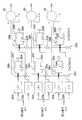
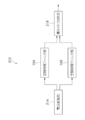
図1に示すように、第1の実施の形態に係るセンサー装置10は、1次元に配列された複数の受光素子を用いて構成され、かつ、入力された光を、複数の受光素子より出力される電流を表わす電流分布に変換すると共に、電流分布に対して重み付けを行うことにより、正に重み付けした電流分布と、負に重み付けした電流分布とを出力する電流変換部14と、正に重み付けされた電流分布に対して、第1の空間時間フィルタを用いて、変換処理を行うことにより、電圧分布に変換する空間時間フィルタ部16Aと、負に重み付けされた検出信号分布に対して、第1の空間時間フィルタとはフィルタ特性が異なる第2の空間時間フィルタを用いて、変換処理を行うことにより、電圧分布に変換する空間時間フィルタ部16Bと、空間時間フィルタ部16A、16Bにより変換された電圧分布を加算することにより強調データを生成して出力する加算部18とを備えている。なお、センサー装置10が、本発明の時空間データ処理装置に対応している。
電流変換部14は、1次元に配列された複数の受光素子を用いて構成され、各受光素子において、刺激として受光した光に応じた電流を出力し、受光素子の各配列位置に対応する電流からなる電流分布を生成する。また、電流変換部14は、生成された電流分布に対して、正の重み付けが行われ、かつ、パルス密度変調又はパルス幅変調による変調が行なわれた同符号のパルス電流分布を空間時間フィルタ部16Aに出力し、負の重み付けが行われ(符号が反転され)、かつ、パルス密度変調又はパルス幅変調による変調が行なわれた反転符号のパルス電流分布を空間時間フィルタ部16Bに出力する。
空間時間フィルタ部16Aは、損失のある拡散方程式で記述された第1の空間時間フィルタを用いて、電流分布と同符号のパルス電流分布を、各配列位置に対する電圧からなる電圧分布に変換して加算部18に出力する。
空間時間フィルタ部16Bは、損失のある拡散方程式で記述され、かつ、第1の空間フィルタとフィルタ特性が異なる第2の空間時間フィルタを用いて、電流分布と反転符号のパルス電流分布を、各配列位置に対する電圧からなる電圧分布に変換して加算部18に出力する。
加算部18は、空間時間フィルタ部16A、16Bより出力された電圧分布の各々を、配列位置毎に加算することにより、刺激の全体像としての検出対象を強調した強調データを生成して出力する。
なお、本実施の形態では、センサー装置10の各部を回路で実現する場合を例に説明する。
センサー装置10の各部を回路で実現すると、図2に示すように、電流変換部14は、対応する配列位置の受光素子からの電流に対して同符号の電流であって、かつ、受光素子からの電流をパルス密度変調又はパルス幅変調により変調したパルス電流を出力する複数の一定電流源20Aと、対応する配列位置の受光素子からの電流に対して反転符号の電流であって、受光素子からの電流をパルス密度変調又はパルス幅変調により変調したパルス電流を出力する複数の一定電流源20Bとで実現される。一定電流源20A、20Bは、各受光素子に対応して設けられている。
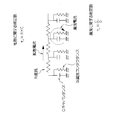
また、空間時間フィルタ部16A、16Bは、隣接する配列位置に対応する一定電流源20Aの出力間を接続するように設けられた複数の抵抗素子22Aと、隣接する配列位置に対応する一定電流源20Bの出力間を接続するように設けられた複数の抵抗素子22Bと、一端が、対応する配列位置の一定電流源20Aの出力に接続され、他端が接地されるように設けられた、抵抗素子24A及び容量素子26Aが並列に接続された複数の並列回路28Aと、一端が、対応する配列位置の一定電流源20Bの出力に接続され、他端が接地されるように設けられた、抵抗素子24B及び容量素子26Bが並列に接続された複数の並列回路28Bと、で実現される。
また、加算部18は、対応する配列位置の並列回路28Aの一端から出力される電圧と、対応する配列位置の並列回路28Bの一端から出力される電圧を加算して出力する複数の加算器30で実現される。
次に、検出信号の分布を強調データに変換する原理について説明する。
まず、配列位置を示す点xに対応する並列回路28Aの一端から出力される電圧V(x)は、以下の(1)式で表される。

ただし、Q0ave,onは、配列位置を示す点x0に対応する一定電流源20Aから出力されるパルス電流の時間平均を示す電流(電荷)であり、Conは、容量素子26Aの容量であり、τd,onは、容量Conと抵抗素子22Aの抵抗値Ronとの乗算で定まる拡散に関する時定数(図3参照)であり、τc,onは、容量Conと抵抗素子24Aの漏洩コンダクタンスGonとの比で定まる漏洩に関する時定数(図3参照)である。
上記(1)式は、損失のある拡散方程式で記述された第1の空間時間フィルタを用いた、電流から電圧への変換を表わしている。
また、配列位置を示す点xに対応する並列回路28Bの一端から出力される電圧V(x)は、同様に、以下の(2)式で表される。

ただし、Q0ave,offは、配列位置を示す点x0に対応する一定電流源20Bから出力されるパルス電流の時間平均を示す電流(電荷)であり、Coffは、容量素子26Bの容量であり、τd,offは、容量Coffと抵抗素子22Bの抵抗値Roffとの乗算で定まる拡散に関する時定数であり、τc,offは、容量Coffと抵抗素子24Bの漏洩コンダクタンスGoffとの比で定まる漏洩に関する時定数である。
上記(2)式は、損失のある拡散方程式で記述された第2の空間時間フィルタを用いた、電流から電圧への変換を表わしている。
また、配列位置を示す点xに対応する並列回路28A、28Bの一端から出力される電圧を加算した電圧(差動電位)Dfv(x)は、以下の(3)式で表される。
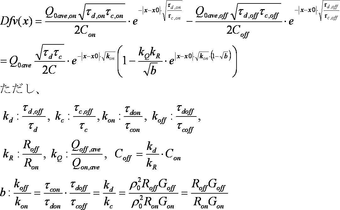
・・・(3)
上記(3)式において、x0=0とすると、以下の(4)式が得られる。

また、上記(4)式で表される電圧を、時間平均の電流(電荷)Q0aveで規格化すると、以下の(5)式で表される。
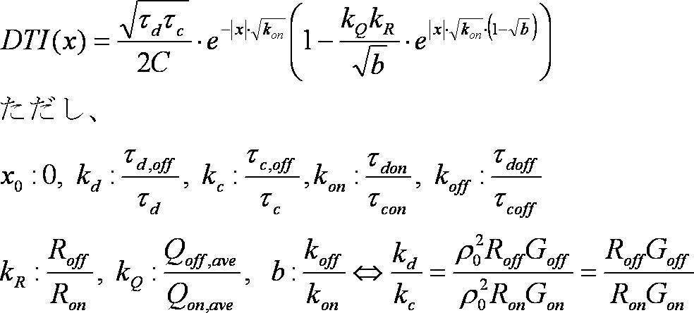
・・・(5)
上記(5)式によって、差動トランスインピーダンスを定義できる。
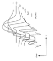
ここで、ラプラシアンガウシアンフィルタの応答と比較して、図4に示すような、上記(5)式のDTI(x)の変化が得られる。図4に示すように、DTI(x)が、有限距離xcと無限距離で0となるように決定される。
有限距離xcでDTI(x)が0となることから、パラメータ間の制約条件として以下の(6)式が得られる。
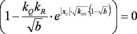
上記(6)式より、以下の(7)式が得られる。

また、パラメータbの範囲が以下の(8)式のように決まる。
0<b<1 ・・・(8)
上記(7)式、(8)式に従って、Dfv(x)は、以下の(9)式で表される。

各種パラメータと共に、パラメータxcを設定して、抵抗素子22A、22B、及び並列回路28A、28Bで実現される空間時間フィルタ部16A、16Bを構成すると、上記(9)式に従って求められる、各配列位置に対する電圧からなる強調データが、複数の加算器30によって実現される加算部18から出力される。
本実施の形態では、並列回路28Aの時定数τc,onと並列回路28Bの時定数τc,offが異なり、かつ、抵抗素子22Aの抵抗値Ronと抵抗素子22Bの抵抗値Roffとが異なることにより、空間時間フィルタ部16Aの第1の空間時間フィルタと、空間時間フィルタ部16Bの第2の空間時間フィルタとは、フィルタ特性が異なっている。なお、並列回路28Aの抵抗素子24Aや並列回路28Bの抵抗素子24Bが誘導成分を有していてもよい。また、並列回路28Aの容量素子26Aの容量、又は並列回路28Bの容量素子26Bの容量が零であってもよい。
また、空間時間フィルタ部16Aの第1の空間時間フィルタと、空間時間フィルタ部16Bの第2の空間時間フィルタとは、所望の強調データ(例えば、検出対象の輪郭を強調したデータ、刺激の強度増大に対して自動的に感度が小さくなるデータ、刺激の強度が大きいほど反応時間が速いデータ、検出対象の移動方向(動きベクトル)に応じてコントラストが変化したデータなど)に応じてフィルタ特性を変更可能に構成されている。すなわち、空間時間フィルタ部16A、16Bを実現する並列回路28A、28Bの抵抗値、容量、及び漏洩コンダクタンスと、抵抗素子22A、22Bの抵抗値とが可変に構成されている。
次に、第1の実施の形態に係るセンサー装置10の作用について説明する。
まず、オペレータによって、所望の強調データに応じて、各種パラメータ(xc、kon、kQ、b、Ron、τd,on、kd)を設定し、第1、2の空間時間フィルタが設定された各種パラメータに応じたフィルタ特性となるように、抵抗素子22A、22B、及び並列回路28A、28Bで実現される空間時間フィルタ部16A、16Bを構成する。
電流変換部14の複数の受光素子の各々に光が入射されると、各受光素子から、入射光に応じた電流が出力され、電流変換部14によって電流分布が生成される。
そして、各配列位置について、一定電流源20A、20Bの各々に対して、対応する配列位置の受光素子より出力された電流が入力され、一定電流源20Aによって、入力電流と同符号の電流であって、パルス密度変調により変調されたパルス電流が出力される。また、一定電流源20Bによって、入力電流に対して反転符号の電流であって、パルス密度変調により変調されたパルス電流が出力される。
次に、各配列位置に対する一定電流源20Aから出力されたパルス電流の分布に基づいて、空間時間フィルタ部16Aを実現する複数の並列回路28A及び複数の抵抗素子22Aによって、電圧分布に変換する。また、各配列位置に対する一定電流源20Bから出力されたパルス電流の分布に基づいて、空間時間フィルタ部16Bを実現する複数の並列回路28B及び複数の抵抗素子22Bによって、電圧分布に変換する。
そして、加算部18を実現する加算器30によって、空間時間フィルタ部16A、16Bより出力された電圧分布に対して、配列位置毎に電圧を加算して、検出対象を強調した強調データを生成して出力する。
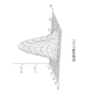
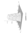
次に、本実施の形態の空間時間フィルタによるデータの変換結果について説明する。
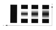
図5Aに示すような、1次元空間で分布し、かつ、時系列的に変化する光を、電流変換部14の1次元に配列された受光素子に入射して、データの変換を行った。また、輪郭を強調した強調データが得られるフィルタ特性となるように、空間時間フィルタの各種パラメータを設定した。
図5B、図5Cに示すように、検出対象の輪郭(刺激の全体像)を強調したデータが、時系列的に変化しながら得られた。
また、パラメータを変更した場合には、図6A、図6Bに示すように、検出対象の輪郭(刺激の全体像)を強調したデータが、時系列的に変化しながら得られた。
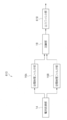
上記の第1の実施の形態において、コンピュータを、重み付け部14、空間時間フィルタ部16A、16B、及び加算部18の各部として機能させるプログラムによる情報処理は、図7のフローチャートに示す変換処理ルーチンで実現することができる。コンピュータは、相互にバスによって接続されたCPU、ROM、及びRAM、並びに必要に応じて接続されたHDDで構成され、これらのプログラムは、コンピュータのCPUに接続されているROMまたはHDD等の記録媒体に記録される。
この変換処理ルーチンを説明すると、ステップ100において、複数の受光素子より出力された電流分布を取得し、ステップ102で、上記ステップ100で取得した電流分布から、同符号でパルス密度変調より変調されたパルス電流の分布を生成し、ステップ104で、上記ステップ100で取得した電流分布から、反転符号でパルス密度変調より変調されたパルス電流の分布を生成する。
そして、ステップ106において、上記ステップ102で生成された、電流分布と同符号のパルス電流分布を、第1の空間時間フィルタを用いて電圧分布に変換し、ステップ108において、上記ステップ104で生成された、電流分布と反転符号のパルス電流分布を、第2の空間時間フィルタを用いて電圧分布に変換する。
次のステップ110では、上記ステップ106で得られた電圧分布と上記ステップ108で得られた電圧分布とを加算することにより強調データを生成して出力し、そして、上記ステップ100へ戻る。
以上説明したように、第1の実施の形態に係るセンサー装置によれば、受光素子からの電流分布と同符号で変調されたパルス電流分布及び反転符号で変調されたパルス電流分布を、フィルタ特性が異なる2つの空間時間フィルタを用いて2つの電圧分布に変換し、変換された2つの電圧分布を加算することにより、簡易な処理で、入力された刺激の分布を強調した強調データを出力することができる。
また、空間的に分布した光が入力されたときに、1次元に配列した受光素子より出力された電流の分布を処理する場合、ソフトウエアによるデータ処理なしに取得情報の処理を非線形かつ高速に処理することができる。
また、局所感度補正が可能となるほか、輪郭抽出、速度推定など膨大な計算時間を有するセンサー情報処理が、簡易なハードウエア構成により高速化することができる。
また、刺激の全体像の境界部を自動的に強調した強調データを出力する場合には、強調データにより、刺激の全体像を把握することが可能となる。また、刺激の強度増大に対して自動的に感度が小さくなる強調データを出力する場合には、過大な刺激に対して自動的に刺激を抑圧する保護が作動し、ダイナミックレンジが広いセンサー感度を実現することができる。また、刺激の強度が大きいほど反応時間が速くなる強調データを出力する場合には、強調データにより、大きな変化のある刺激ほど高速に検出することが可能となる。また、刺激の移動方向に対してコントラストが変化する強調データを出力する場合には、強調データのコントラストから瞬時に刺激の移動方向を推定することができる。
次に、第2の実施の形態について説明する。なお、第1の実施の形態と同様の構成となる部分については、同一符号を付して説明を省略する。
第2の実施の形態では、空間時間フィルタ部より出力された電圧分布に対して重み付け加算を行っている点が、第1の実施の形態と異なっている。
図8に示すように、第2の実施の形態に係るセンサー装置210は、入力された光を、複数の受光素子より出力される電流を表わす電流分布の各電流をパルス幅変調又はパルス密度変調により変調して、変調されたパルス電流分布を出力する電流変換部214と、電流変換部214より出力されたパルス電流分布に対して、第1の空間時間フィルタを用いて、変換処理を行うことにより、電圧分布に変換する空間時間フィルタ部16Aと、電流変換部214より出力されたパルス電流分布に対して、第2の空間時間フィルタを用いて、変換処理を行うことにより、電圧分布に変換する空間時間フィルタ部16Bと、空間時間フィルタ部16Aにより変換された電圧分布に対して正の重み付けを行い、空間時間フィルタ部16Bにより変換された電圧分布に対して負の重み付けを行うと共に、重み付けされた電圧分布の各々を加算することにより強調データを生成して出力する重み付け加算部218とを備えている。
重み付け加算部218は、空間時間フィルタ部16Aにより変換された電圧分布に対して正の重み付けを行い、空間時間フィルタ部16Bにより変換された電圧分布に対して負の重み付けを行うと共に、配列位置毎に電圧を加算して重み付けされた電圧分布の各々を加算することにより、刺激の全体像としての検出対象を強調した強調データを生成して出力する。
電流変換部214は、対応する配列位置の受光素子からの電流に対してパルス密度変調又はパルス幅変調により変調したパルス電流を出力する複数の一定電流源(図示省略)で実現される。
重み付け加算部218は、対応する配列位置の並列回路28Aの一端から出力される電圧を同符号で出力する複数の同符号出力回路(図示省略)と、対応する配列位置の並列回路28Bの一端から出力される電圧を反転符号にして出力する複数の反転符号出力回路(図示省略)と、対応する同符号出力回路の出力と対応する反転符号出力回路の出力とを加算して出力する複数の加算器30で実現される。
第2の実施の形態では、第1の実施の形態と同様に、パルス信号の分布を強調データに変換するため、強調データに変換する原理について説明を省略する。
次に、第2の実施の形態に係るセンサー装置10の作用について説明する。
まず、各種パラメータを設定し、第1、2の空間時間フィルタが設定された各種パラメータに応じたフィルタ特性となるように、抵抗素子22A、22B、及び並列回路28A、28Bで実現される空間時間フィルタ部16A、16Bを構成する。
電流変換部214の複数の受光素子の各々に光が入射されると、各受光素子から、入射光に応じた電流が出力され、電流の分布が生成される。そして、各配列位置について、一定電流源に対して、対応する配列位置の受光素子より出力された電流が入力され、一定電流源によって、パルス密度変調により変調されたパルス電流が出力される。
次に、各配列位置に対する一定電流源から出力されたパルス電流の分布に基づいて、空間時間フィルタ部16Aを実現する複数の並列回路28A及び複数の抵抗素子22Aによって、電圧分布に変換する。また、各配列位置に対する一定電流源から出力されたパルス電流の分布に基づいて、空間時間フィルタ部16Bを実現する複数の並列回路28B及び複数の抵抗素子22Bによって、電圧分布に変換する。
そして、重み付け加算部218を実現する同符号出力部によって、空間時間フィルタ部16Aより出力された電圧分布を同符号で出力し、反転符号出力部によって、空間時間フィルタ部16Bより出力された電圧分布を反転符号にして出力する。また、重み付け加算部218を実現する加算器30によって、複数の同符号出力部の出力からなる電圧分布、及び複数の反転符号出力部の出力からなる電圧分布に対して、配列位置毎に電圧を加算して、検出対象を強調した強調データを生成して出力する。
上記の第2の実施の形態において、コンピュータを、電流変換部214、空間時間フィルタ部16A、16B、及び重み付け加算部218の各部として機能させるプログラムによる情報処理は、以下に説明する変換処理ルーチンで実現することができる。
まず、複数の受光素子より出力された電流分布を取得し、取得した電流分布から、パルス密度変調より変調されたパルス電流の分布を生成する。そして、生成されたパルス電流分布を、第1の空間時間フィルタを用いて電圧分布に変換し、また、生成されたパルス電流分布を、第2の空間時間フィルタを用いて電圧分布に変換する。
次に、得られた一方の電圧分布を同符号の電圧分布として出力し、他方の電圧分布を反転符号の電圧分布として出力する。そして、得られた同符号の電圧分布と反転符号の電圧分布とを加算することにより強調データを生成して出力し、そして、最初の処理に戻る。
このように、受光素子からの電流分布から変調されたパルス電流分布を、フィルタ特性が異なる2つの空間時間フィルタを用いて2つの電圧分布に変換し、変換された2つの電圧分布を重み付け加算することにより、簡易な処理で、入力された刺激の分布を強調した強調データを出力することができる。
なお、上記の実施の形態の電流変換部214において、更に、電流分布に対して重み付けを行うと共に、パルス密度変調又はパルス幅変調による変調を行うようにしてもよい。この場合には、各々異なる重み付けがされたパルス電流分布が、空間時間フィルタ部16A、16Bに出力される。
次に第3の実施の形態について説明する。なお、第3の実施の形態に係るセンサー装置の構成は、第1の実施の形態と同様の構成となるため、同一符号を付して説明を省略する。
第3の実施の形態では、2次元に配列された受光素子によって、各配列位置に対する電流の分布を出力している点と、空間時間フィルタによって、2次元に分布された電流分布を、電圧分布に変換している点とが、第1の実施の形態と主に異なっている。
第3の実施の形態に係るセンサー装置では、空間時間フィルタ部16Aに、複数の並列回路28Aが2次元の配列位置の各々に対応して設けられ、空間時間フィルタ部16Bに、複数の並列回路28Bが2次元の配列位置の各々に対応して設けられている。
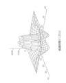
また、本実施の形態では、配列位置を示す点xに対応する並列回路28A、28Bの一端から出力される電圧を加算した電圧を、時間平均の電流(電荷)Q0aveで規格化すると、図9に示すような応答DTI(x)が得られる。
得られる電流や電圧が2次元で分布しており、DTI(x)の応答では、受光素子により出力される電流のピクセルサイズが考慮され、ラプラシアンガウシアンフィルタの応答よりも、ピクセル近傍でシャープな応答となっている。
なお、第3の実施の形態に係るセンサー装置の他の構成及び作用について、第1の実施の形態と同様であるため、説明を省略する。
次に、本実施の形態の空間時間フィルタによるデータの変換結果について説明する。
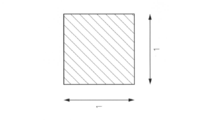
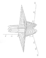
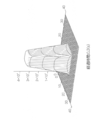
図10Aに示すような、1m四方の四角形の検出対象物から反射された光を、電流変換部14の2次元に配列された受光素子に入力して、データの変換を行った。このとき、図10Bに示すように、検出対象物の輪郭(刺激の全体像)を強調した強調データが得られた。
また、得られる強調データの時間的変化を調べると、まず、図11に示すように、検出対象物を滑らかに表わした強調データが得られ(経過時間0.3秒)、次に、図12に示すように、検出対象物の中心部を強調した強調データが得られ(経過時間2.3秒)、そして、図13、14に示すように、検出対象物の輪郭、特に、検出対象物の頂点部分を強調した強調データが得られた(経過時間40秒、51秒)。
以上説明したように、第3の実施の形態に係るセンサー装置によれば、同符号で変調されたパルス電流分布及び反転符号で変調されたパルス電流分布を、フィルタ特性が異なる2つの空間時間フィルタを用いて2つの電圧分布に変換し、変換された2つの電圧分布を加算することにより、簡易な処理で、入力された刺激の分布を強調した強調データを出力することができる。
また、空間的に分布した光に基づいて、2次元に配列した受光素子より出力された電流の分布を処理する場合に、ソフトウエアによるデータ処理なしに取得情報の処理を非線形かつ高速に処理することができる。
なお、センサー装置を回路で実現した場合を例に説明したが、上記第1の実施の形態で説明したように、コンピュータをセンサー装置の各部として機能させるためのプログラムによって実現するようにしてもよい。
また、図15に示すように、空間時間フィルタ部16A、16Bの入力点より前の位置に、入力刺激に対応する電流(パルス電流)を遮断し、かつ、遮断するか否かを切り替えることが可能なシャッターを設けるようにしてもよい。これによって、必要に応じて、図12に示すような検出対象物の中心部の強調データを得る事ができる。また、電流変換部14より前の位置に、入力される刺激を遮断し、かつ、遮断するか否かを切り替えることが可能なシャッターを設けるようにしてもよい。
また、上記の第1の実施の形態~第3の実施の形態では、センサー装置に本発明を適用した場合を例に説明したが、これに限定されるものではなく、高機能カメラに本発明を適用してもよい。この場合には、入力の強度に応じた局所自動感度補正、モーションキャプチャ、低SN比画像からの輪郭抽出 又は、同一方向又は同一周期で変動しているターゲットの抽出が可能な高機能カメラを提供することができる。
また、電流変換部が、受光素子を備えている場合を例に説明したが、これに限定されるものではなく、撮像装置によって出力された複数の画素値からなる画像データが、刺激として電流変換部に入力されるように構成されていてもよい。この場合には、電流変換部は、各画素値に応じたパルス電流からなるパルス電流分布を出力するようにすればよい。
次に、第4の実施の形態について説明する。なお、第4の実施の形態に係るセンサー装置の構成は、第1の実施の形態と同様の構成となるため、同一符号を付して説明を省略する。
第4の実施の形態では、入力された刺激を検知する複数のセンサー素子が設けられた電流変換部を用いている点が、第1の実施の形態と異なっている。
第4の実施の形態に係るセンサー装置の電流変換部14は、1次元に配列され、かつ、入力された光以外の刺激(例えば、熱、音、臭い、触刺激など)を検出する複数のセンサー素子を用いて構成され、各センサー素子において、入力された刺激に応じた検出信号を出力する。また、電流変換部14は、センサー素子の各配列位置に対応する検出信号に対して、正の重み付け及び負の重み付けを行い、正の重み付けが行われた同符号の検出信号に応じたパルス電流に変換してパルス電流分布を出力すると共に、負の重み付けが行われた反転符号の検出信号に応じたパルス電流に変換してパルス電流分布を出力する
加算部18は、空間時間フィルタ部16A、16Bより出力された電圧分布の各々を、配列位置毎に加算することにより、刺激の全体像を強調した強調データを生成して出力する。
なお、第4の実施の形態のセンサー装置の他の構成及び作用については、第1の実施の形態と同様であるため、説明を省略する。
このように、センサー素子からの検出信号に対して同符号の検出信号から変調されたパルス電流分布及び反転符号の検出信号から変調されたパルス電流分布を、フィルタ特性が異なる2つの空間時間フィルタを用いて2つの電圧分布に変換し、変換された2つの電圧分布を加算することにより、簡易な処理で、入力された刺激の分布を強調した強調データを出力することができる。
なお、センサー装置を回路で実現した場合を例に説明したが、上記第1の実施の形態で説明したように、コンピュータをセンサー装置の各部として機能させるためのプログラムによって実現するようにしてもよい。
次に、第5の実施の形態について説明する。なお、第5の実施の形態に係るセンサー装置の構成は、第1の実施の形態と同様の構成となるため、同一符号を付して説明を省略する。
第5の実施の形態では、空間時間フィルタ部及び加算部を、1つの数式を用いた演算によって実現している点が、第1の実施の形態と異なっている。
第5の実施の形態に係るセンサー装置では、コンピュータによって、空間時間フィルタ部16A、16B、及び加算部18の処理と等価な1つの数式を用いた演算を行う。以下に、空間時間フィルタ部16A、16B、及び加算部18の処理と等価な1つの数式について説明する。なお、簡単のため、C=0、Qoave:Qoave,on=Qoave,offの場合について説明を行っている。
まず、負の重み付けした電流分布を空間時間フィルタ部16Bにより変換した電圧分布Voffを、正の重み付けした電流分布を空間時間フィルタ部16Aにより変換した電圧分布Vonを基準にすると共に、2つのパラメータR,Gによるテーラ級数展開を行うことにより、以下の(10)式が得られる。

・・・(10)
ただし、Goffは、抵抗素子24Bの漏洩コンダクタンスに相当する値であり、Roffは、抵抗素子22Bの抵抗値Roffに相当する値である。
ここで、以下の(11)式~(14)式を仮定する。
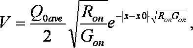


ただし、Vは、空間時間フィルタ部16A、16Bの出力電圧に相当する値であり、xは、配列位置を示す点である。また、Q0aveは、配列位置を示す点x0に対応する一定電流源から出力されるパルス電流の時間平均を示す電流(電荷)である。
Off回路網のパラメータRoff、GoffはOn回路網のパラメータを基準として夫々(13)、(14)式で表すことが出来る。したがって、off回路網とon回路網の差分パラメータΔR、ΔGとOn回路網のパラメータを使って見通しの良い差動電圧Dfv(x)の計算式を得ることが出来る。
上記(10)式~(14)式により、加算部18によって出力される配列位置xに対する差動電圧Dfv(x)は、以下の(15)式によって近似される。

第5の実施の形態に係るセンサー装置では、電流変換部14により生成された、同符号でパルス密度変調より変調されたパルス電流の分布を入力とし、空間時間フィルタ部16A、16B、及び加算部18の処理と等価な上記の(15)式を用いた演算を行って、配列位置x毎に電圧を演算し、電圧分布である強調データを出力する。
第5の実施の形態に係る変換処理ルーチンでは、まず、複数の受光素子より出力された電流分布を取得し、取得した電流分布から、同符号でパルス密度変調より変調されたパルス電流の分布を生成する。
そして、生成された、電流分布と同符号のパルス電流分布を入力とし、上記(15)式に従って、差動電圧の分布を表わす強調データを生成して出力する。
以上説明したように、第5の実施の形態に係るセンサー装置によれば、空間時間フィルタ部と加算部との処理を近似した、空間時間フィルタのフィルタ特性の差分に基づく近似式に従って、強調データを生成することができる。また、1つの数式の演算で実現するため、高速に処理することができる。
なお、上記の実施の形態では、1次の項まで用いて近似した数式の演算によって、強調データを出力する場合を例に説明したが、これに限定されるものではなく、2次以上の項を用いて近似した数式の演算によって、強調データを出力するようにしてもよい。また、等価な出力をするものであれば、他の近似式でもよい。
次に、第6の実施の形態について説明する。なお、第1の実施の形態と同様の構成となる部分については、同一符号を付して説明を省略する。
第6の実施の形態では、加算部によって出力された電圧分布に対して、更にフィルタ処理を行っている点が、第1の実施の形態と異なっている。
図16に示すように、第6の実施の形態に係るセンサー装置610は、電流変換部14と、空間時間フィルタ部16A、16Bと、加算部18と、加算部18によって出力された電圧分布に対して、フィルタ処理を行う出力フィルタ部618とを備えている。
出力フィルタ部618は、加算部18より出力された強調データとしての電圧分布に対して、配列位置毎にフィルタ処理を行って、フィルタ処理が行われた強調データを出力する。
出力フィルタ部618は、例えば、半波整流を行うフィルタ、全波整流を行うフィルタ、絶対電圧を出力するフィルタ、実効電圧(の瞬時出力あるいは時間移動平均)を出力するフィルタなどの、非線形処理を行うフィルタを用いて、配列位置毎にフィルタ処理を行う。なお、ローパスフィルタやバンドパスフィルタ、ハイパスフィルタ、微分フィルタ、積分フィルタなどの線形処理を行うフィルタを用いて、配列位置毎にフィルタ処理を行うようにしてもよい。
電流変換部14で、パルス幅30μsの電流パルスを用いたパルス密度変調を行ない、空間時間フィルタ部16A、16B及び加算部18で、差動電圧を演算し、出力フィルタ部618により、実効電圧を出力する場合において、0~28000Hzのパルス密度となるように1点に刺激を与えて、対応する配列位置の出力電圧を計測すると、図17に示すような、パルス密度に応じた差動電圧が得られる。微弱刺激であるときの感度が高くなるため、人間の感覚により近い出力が得られる。
また、電流変換部14で、デューティ比50%の電流パルスを用いたパルス幅変調を行ない、空間時間フィルタ部16A、16B及び加算部18で、差動電圧を演算し、出力フィルタ部618により、実効電圧を出力する場合において、10~3000Hzの周波数の刺激を1点に与えて、対応する配列位置の出力電圧を計測すると、図18に示すような、電流パルスの周波数に応じた差動電圧が得られる。特定の周波数(例えば100Hz)に対する感度が高くなるため、人間の感覚により近い出力が得られる。
なお、第6の実施の形態に係るセンサー装置の他の構成及び作用については、第1の実施の形態と同様のであるため、説明を省略する。
次に、第7の実施の形態について説明する。なお、第7の実施の形態に係るセンサー装置の構成は、第6の実施の形態と同様の構成となっているため、同一符号を付して説明を省略する。
第7の実施の形態では、加算部によって出力された電圧分布に対して、空間フィルタを用いて更にフィルタ処理を行っている点が、第6の実施の形態と異なっている。
第7の実施の形態に係るセンサー装置では、出力フィルタ部618において、配列位置の各々について、フィルタ処理により得られる出力が大きいほど、当該配列位置の周囲の配列位置に対するフィルタ処理のゲインを下げるように調整する。
センサー装置の各部を回路で実現すると、図19に示すように、出力フィルタ部618は、複数の加算器30に対応して設けられた複数のフィルタ処理部720を備えている。
フィルタ処理部720は、対応する加算器30の出力と、隣接するフィルタ処理部720の出力とを入力し、隣接するフィルタ処理部720の出力をフィードバックして、ゲインを調整すると共に、加算器30からの出力に対してフィルタ処理を行っている。なお、本実施の形態では、ゲインの調整により、フィルタ処理部の出力が大きいほど、周囲のフィルタ処理部のゲインを下げている。
本実施の形態に係るセンサー装置は、刺激が加えられた配列位置では、周囲の感度をいったん上げた後、感度を下げるように作用する。すなわち、近傍が刺激されることにより、初期感度が上げられ、刺激過敏状態が実現される。また、定常刺激では、互いに感度を下げる方向に作用し、周囲の感度を抑圧する。
なお、第7の実施の形態に係るセンサー装置の他の構成及び作用については、第1の実施の形態と同様のであるため、説明を省略する。
また、上記の第6の実施の形態で説明した出力フィルタ部と上記の第7の実施の形態で説明した出力フィルタ部とを組み合わせて用いるように構成してもよい。
また、出力される強調データの電圧分布が1次元である場合を例に説明したが、これに限定されるものではなく、2次元以上の電圧分布が出力される場合に、本発明を適用してもよい。この場合には、2次元以上の配列位置に対応する空間フィルタを用いてフィルタ処理を行うようにすればよい。
また、フィルタ処理部720は、隣接するフィルタ処理部の出力をフィードバックする場合を例に説明したが、これに限定されるものではなく、フィルタ処理部720は、対応する加算器30の出力と、周辺のフィルタ処理部720の出力とを入力し、周辺のフィルタ処理部720の出力をフィードバックして、ゲインを調整すると共に、加算器30からの出力に対してフィルタ処理を行うようにしてもよい。
また、出力される強調データの電圧分布が1次元である場合を例に説明したが、これに限定されるものではなく、2次元以上の電圧分布が出力される場合に、本発明を適用してもよい。この場合には、2次元以上の配列位置に対応する空間フィルタを用いてフィルタ処理を行うようにすればよい。
また、フィルタ処理部720は、隣接するフィルタ処理部の出力をフィードバックする場合を例に説明したが、これに限定されるものではなく、フィルタ処理部720は、対応する加算器30の出力と、周辺のフィルタ処理部720の出力とを入力し、周辺のフィルタ処理部720の出力をフィードバックして、ゲインを調整すると共に、加算器30からの出力に対してフィルタ処理を行うようにしてもよい。
次に、第8の実施の形態について説明する。なお、第8の実施の形態では、ロボットハンドを備えたロボット装置に、本発明を適用した場合を例に説明する。また、第1の実施の形態と同様の構成となる部分については、同一符号を付して説明を省略する。
図20に示すように、第8の実施の形態に係るロボット装置810は、ロボットハンド812と、ロボットハンド812からのセンサ出力を入力として、ロボットハンド812をフィードフォワード制御する制御用センサー装置813と、ロボットハンド812を撮像すると共に、ロボットハンド812の位置を検出してロボットハンド812の各部の位置情報を出力するイメージセンサ814と、イメージセンサ814からのセンサ出力を入力とするイメージ用センサー装置815と、制御用センサー装置813及びイメージ用センサー装置815からの出力に基づいてフィードバック制御を行うフィードバック制御部816とを備えている。
図21に示すように、ロボットハンド812は、複数の関節部820と、関節部820を介して接続された複数の指部822と、関節部820を介して指部822と接続された掌部824と、指部822及び掌部824を覆うように上側に設けられ、かつ、指部822及び掌部824に作用する応力の分布を検出する分布応力センサ826と、掌部824を支持するロボットアーム828とを備えている。
また、ロボットハンド812は、複数の関節部820と、ロボットアーム828に設けられた関節部830とに設けられた、関節を曲げたり伸ばしたりするように駆動するための複数のアクチュエータからなるアクチュエータ群832を備えている。
分布応力センサ826としては、作用する応力の分布を検出する従来既知のセンサを用いればよく、例えば、電気抵抗を有する微小球や容量性の微小球を分布させたシートと、マトリックス状に配置した電極とを用いたセンサによって、作用する応力の分布を検出する。
制御用センサー装置813及びイメージ用センサー装置815は、上記の第1の実施の形態で説明した複数の空間時間フィルタ部16A、16Bを備えたセンサー装置10と同様の構成であるため、詳細な説明を省略する。
制御用センサー装置813は、分布応力センサ826から出力される、指部822及び掌部824の各位置(配列位置)に対する応力の分布を示すデータを入力とし、指部822及び掌部824の各位置(配列位置)に印加する力学的力に対応する出力データ(強調データ)を、アクチュエータ群832に対して出力する(フィードフォワード制御)。
指部822の関節部820に設けられたアクチュエータの各々は、制御用センサー装置813から入力されるデータについて、その値が大きいほど、関節を曲げる方向の駆動力が大きくなる。ロボットアーム828の関節部830に設けられたアクチュエータは、制御用センサー装置813から入力されるデータについて、その入力されるデータの値が大きいほど、掌部824の位置を高く上げる方向の駆動力が大きくなる。
イメージセンサ814は、ロボットハンド812を撮像して、画像認識処理を行って、ロボットハンド812の指部822及び掌部824の位置を検出し、指部822及び掌部824の各部の位置情報を演算する。
イメージ用センサー装置815は、イメージセンサ814から出力される、指部822及び掌部824の各位置(配列位置)の位置情報を示すデータを入力とし、指部822及び掌部824の各位置(配列位置)に対する出力データ(強調データ)を、フィードバック制御部816に出力する。
フィードバック制御部816は、制御用センサー装置813から出力される各配列位置に対する応力の出力データ(強調データ)と、イメージ用センサー装置815から出力される各配列位置に対する出力データ(強調データ)とに基づいて、フィードバック制御を行う。すなわち、フィードバック制御に基づく指部822及び掌部824の各位置(配列位置)の出力データを、アクチュエータ群832に対して出力して、指部822及び掌部824の各位置に対応するアクチュエータに、対応する制御データを入力する。
次に、第8の実施の形態に係るロボット装置810の作用について説明する。
まず、分布応力センサ826によって、指部822及び掌部824の各位置に作用した応力を検出すると共に、イメージセンサ814によって、指部822及び掌部824の各位置の位置情報を検出する。
そして、制御用センサー装置813によって、分布応力センサ826から出力された各位置のデータに基づいて、強調データが生成され、アクチュエータ群832にフィードフォワード制御信号を出力すると共に、フィードバック制御部816に出力する。ロボットハンド812のアクチュエータ群832では、入力されたデータに応じて関節部820、830を駆動する。
また、イメージ用センサー装置815によって、イメージセンサ814から出力された各位置の位置情報に基づいて、強調データが生成され、フィードバック制御部816に出力する。
フィードバック制御部816は、制御用センサー装置813からの強調データ、及びイメージ用センサー装置815からの強調データに基づいて、アクチュエータ群832のフィードバック制御を行う。ロボットハンド812のアクチュエータ群832では、フィードバック制御に従って関節部820、830を駆動する。
例えば、図22Aに示すように、物体が掌部824に衝突すると、制御用センサー装置813によって、図22Bに示すような、指部822及び掌部824の各位置に対する強調データが出力される。これによって、指部822の関節を伸ばし、掌部824を下げる方向の力学的力に対応する制御力がアクチュエータ群832により作り出され関節部820、830が駆動される。これによって衝突直後は、物体の衝突による衝撃を吸収するように、掌部824の高さを急速に低下させる方向の強力な制御力が作り出される(制御力により加速度が指定されるので、衝撃直後は掌の位置は動かない)。
そして、衝突後、時間が経過すると、制御用センサー装置813によって、図23Bに示すような、掌部824の応力に対する出力が低下し、掌部824の周辺の指部822の応力に対する出力が低下した(指部822の関節を閉じる極性の値が出力された)強調データが出力される。これによって、指部822の関節を曲げるようにアクチュエータ群832が関節部820、830を駆動する。また、掌部824の高さは図23Aに示すように、物体の衝突による衝撃を吸収するように、高さが低下した状態となっている。
また、衝突後、十分な時間が経過すると、制御用センサー装置813によって、図24Bに示すような、掌部824の位置に対する出力が更に低下し、掌部824の周辺の指部822の位置に対する出力が更に低下した(指部822の関節を閉じる極性の値が増加した)強調データが出力される。また、フィードバック制御部816によって、掌部824の位置が初期値に回復するようにフィードバック制御される。これによって、図24Aに示すように、掌部824の高さが初期値に戻ると共に、指部822の関節を更に曲げるようにアクチュエータ群832が関節部820、830を駆動する。
以上説明したように、第8の実施の形態に係るロボット装置によれば、入力された刺激の分布を強調した強調データを用いて、ロボットハンドを制御することができる。また、2つのセンサー装置の各々の強調データに基づいて、フィードバック制御を行うことにより、ロボットハンドを正確に制御することができる。
また、上記の第1の実施の形態~第8の実施の形態では、1次元又は2次元に配列された受光素子又はセンサー素子から、1次元又は2次元に分布した検出信号の分布を取得する場合を例に説明したが、これに限定されるものではなく、1次元以上に配列された受光素子又はセンサー素子の出力から、3次元以上の次元で分布された検出信号の分布を取得するようにしてもよい。
また、空間時間フィルタが2つである場合を例に説明したが、これに限定されるものではなく、3つ以上の空間時間フィルタを用いて変換するようにしてもよい。この場合には、3つ以上のパルス信号分布を、3つ以上の空間時間フィルタで各々電圧分布に変換するようにすればよい。
また、パルス信号分布に対して、1段の空間時間フィルタのみで変換を行う場合を例に説明したが、これに限定されるものではなく、多段の空間時間フィルタによって変換を行うようにしてもよい。例えば、パルス信号分布に対して、1段目の空間時間フィルタによって、電圧分布に変換し、1段目の空間時間フィルタと2段目の空間時間フィルタとの間に設けられた電流変換部によって、電圧分布を電流分布に変換し、そして、1段目の空間時間フィルタとは異なる2段目の空間時間フィルタによって、電圧分布を更に変換するようにしてもよい。また、空間時間フィルタが3段以上であってもよい。
また、空間時間フィルタが損失のある拡散方程式で記述される場合を例に説明したが、これに限定されるものではなく、損失あのある拡散方程式に、時間に関する二階微分項を付加した式で、空間時間フィルタが記述されるように構成してもよい。例えば、損失のある拡散方程式とみなせる波動方程式で記述された空間時間フィルタを用いてもよい。
また、電流変換部によってパルス電流分布を出力する場合を例に説明したが、これに限定されるものではなく、入力された刺激に応じた電流値の電流からなる電流分布を出力するようにしてもよい。
また、本発明のプログラムは、記録媒体に格納して提供することも可能である。
10、210、610 センサー装置
14、214 電流変換部
16A、16B 空間時間フィルタ部
18 加算部
20A、20B 一定電流源
22A、22B、24A、24B 抵抗素子
26A、26B 容量素子
28A、28B 並列回路
30 加算器
218 重み付け加算部
618 出力フィルタ部
720 フィルタ処理部
810 ロボット装置
812 ロボットハンド
813 制御用センサー装置
815 イメージ用センサー装置
14、214 電流変換部
16A、16B 空間時間フィルタ部
18 加算部
20A、20B 一定電流源
22A、22B、24A、24B 抵抗素子
26A、26B 容量素子
28A、28B 並列回路
30 加算器
218 重み付け加算部
618 出力フィルタ部
720 フィルタ処理部
810 ロボット装置
812 ロボットハンド
813 制御用センサー装置
815 イメージ用センサー装置
Claims (27)
- 1次元以上の次元で配列された配列位置の各々に対して入力された刺激に応じて変化する電流からなる電流分布に対して、前記電流分布毎に重み付けされた複数の電流分布を出力する電流変換手段と、
損失のある拡散方程式で記述され、かつ、フィルタ特性が各々異なる複数の空間フィルタの各々を用いて、前記電流変換手段によって出力された前記複数の電流分布を、各配列位置に対する電圧からなる複数の電圧分布に変換するフィルタ変換手段と、
前記フィルタ変換手段によって変換された前記複数の電圧分布を前記配列位置毎に加算し、前記加算して得られた電圧分布を出力する加算手段と、
を含む時空間データ処理装置。 - 1次元以上の次元で配列された配列位置の各々に対して入力された刺激に応じて変化する電流からなる電流分布を出力する電流変換手段と、
損失のある拡散方程式で記述され、かつ、フィルタ特性が各々異なる複数の空間フィルタの各々を用いて、前記電流変換手段によって出力された電流分布を、各配列位置に対する電圧からなる複数の電圧分布に変換するフィルタ変換手段と、
前記フィルタ変換手段によって変換された前記複数の電圧分布に対して、前記電圧分布毎に重み付けすると共に前記配列位置毎に加算し、前記加算して得られた電圧分布を出力する加算手段と、
を含む時空間データ処理装置。 - 前記電流変換手段は、前記電流分布に対して、前記電流分布毎に重み付けされた複数の電流分布を出力し、
前記フィルタ変換手段は、前記複数の空間フィルタの各々を用いて、前記電流変換手段によって出力された複数の電流分布を、前記複数の電圧分布に変換する請求項2記載の時空間データ処理装置。 - 前記電流変換手段は、前記電流分布に基づいて、前記電流分布毎に重み付けされ、かつ、各配列位置の電流をパルス幅変調又はパルス密度変調により変調した複数の電流分布を出力する請求項1記載の時空間データ処理装置。
- 前記電流変換手段は、前記電流分布の各配列位置の電流を、パルス幅変調又はパルス密度変調により変調した電流分布を出力する請求項2又は3記載の時空間データ処理装置。
- 前記空間フィルタの各々を、前記電流変換手段により出力された、対応する前記電流分布における隣接する前記配列位置の電流の出力間を接続するように設けられた複数の抵抗素子と、各々の一端を各配列位置の電流の出力を接続し、かつ、各々の他端を接地するように設けられた、抵抗素子及び容量素子を並列に接続した複数の並列回路と含んで構成した請求項1又は4記載の時空間データ処理装置。
- 前記空間フィルタの各々を、前記電流変換手段により出力された、前記電流分布における隣接する前記配列位置の電流の出力間を接続するように設けられた複数の抵抗素子と、各々の一端を各配列位置の電流の出力を接続し、かつ、各々の他端を接地するように設けられた、抵抗素子及び容量素子を並列に接続した複数の並列回路と含んで構成した請求項2、3、又は5記載の時空間データ処理装置。
- 前記空間フィルタの各々に設けられた前記並列回路の時定数が、他の空間フィルタと異なるように構成した請求項6又は7記載の時空間データ処理装置。
- 前記空間フィルタの各々に設けられた、隣接する前記配列位置の電流の出力間を接続した前記抵抗素子の抵抗値が、他の空間フィルタと異なるように構成した請求項6~請求項8の何れか1項記載の時空間データ処理装置。
- 前記並列回路の抵抗素子は、誘導成分を有する請求項6~請求項9の何れか1項記載の時空間データ処理装置。
- 前記並列回路の容量素子の容量を零とした請求項6~請求項10の何れか1項記載の時空間データ処理装置。
- 前記複数の空間フィルタは、2つの空間フィルタであって、
前記電流変換手段は、正の重み付けが行われた電流分布と、負の重み付けが行われた電流分布とを出力し、
前記フィルタ変換手段は、前記2つの空間フィルタの各々を用いて、前記電流変換手段によって出力された2つの電流分布を、2つの電圧分布に変換する請求項1、4、又は6記載の時空間データ処理装置。 - 前記複数の空間フィルタは、2つの空間フィルタであって、
前記フィルタ変換手段は、2つの空間フィルタの各々を用いて、前記電流変換手段によって出力された電流分布を、2つの電圧分布に変換し、
前記加算手段は、前記フィルタ変換手段によって変換された前記2つの電圧分布の一方に対して正の重み付けを行い、他方に対して負の重み付けを行うと共に、前記配列位置毎に加算し、前記加算して得られた電圧分布を出力する請求項2、3、5、又は7記載の時空間データ処理装置。 - 前記複数の空間フィルタとは異なる複数の第2空間フィルタの各々を用いて、前記フィルタ変換手段によって変換された前記複数の電圧分布の各々を変換する第2フィルタ変換手段を更に含み、
前記加算手段は、前記第2フィルタ変換手段によって変換された前記複数の電圧分布を前記配列位置毎に加算し、前記加算して得られた電圧分布を出力する請求項1、4、6、又は12記載の時空間データ処理装置。 - 前記複数の空間フィルタとは異なる複数の第2空間フィルタの各々を用いて、前記フィルタ変換手段によって変換された前記複数の電圧分布の各々を変換する第2フィルタ変換手段を更に含み、
前記加算手段は、前記第2フィルタ変換手段によって変換された前記複数の電圧分布に対して、前記電圧分布毎に重み付けすると共に前記配列位置毎に加算し、前記加算して得られた電圧分布を出力する請求項2、3、5、7、又は13記載の時空間データ処理装置。 - 前記複数の空間フィルタを、所望の電圧分布に応じてフィルタ特性を変更可能とした請求項1~請求項15の何れか1項記載の時空間データ処理装置。
- 前記空間フィルタを、損失のある拡散方程式に時間に関する二階微分項を付加した式で記述した請求項1~請求項16の何れか1項記載の時空間データ処理装置。
- 前記空間フィルタへ入力位置より前に設けられた、入力される刺激、又は電流分布を遮断し、かつ、前記遮断するか否かを切り替え可能なシャッターを更に含む請求項1~請求項17の何れか1項記載の時空間データ処理装置。
- 前記加算手段によって出力された電圧分布に対して、前記配列位置毎にフィルタ処理を行うフィルタ処理手段を更に含む請求項1~請求項18の何れか1項記載の時空間データ処理装置。
- 前記フィルタ処理手段は、前記配列位置の各々について、前記フィルタ処理により得られる出力が大きいほど、該配列位置の周辺の配列位置に対するフィルタ処理のゲインを下げる請求項19記載の時空間データ処理装置。
- コンピュータを、
1次元以上の次元で配列された配列位置の各々に対して入力された刺激に応じて変化する電流からなる電流分布に対して、前記電流分布毎に重み付けされた複数の電流分布を出力する電流変換手段、
損失のある拡散方程式で記述され、かつ、フィルタ特性が各々異なる複数の空間フィルタの各々を用いて、前記電流変換手段によって出力された前記複数の電流分布を、各配列位置に対する電圧からなる複数の電圧分布に変換するフィルタ変換手段、及び
前記フィルタ変換手段によって変換された前記複数の電圧分布を前記配列位置毎に加算し、前記加算して得られた電圧分布を出力する加算手段
として機能させるためのプログラム。 - コンピュータを、
損失のある拡散方程式で記述され、かつ、フィルタ特性が各々異なる複数の空間フィルタの各々を用いて、1次元以上の次元で配列された配列位置の各々に対して入力された刺激に応じて変化する電流からなる電流分布を出力する電流変換手段、
前記電流変換手段によって出力された電流分布を、各配列位置に対する電圧からなる複数の電圧分布に変換するフィルタ変換手段、及び
前記フィルタ変換手段によって変換された前記複数の電圧分布に対して、前記電圧分布毎に重み付けすると共に前記配列位置毎に加算し、前記加算して得られた電圧分布を出力する加算手段
として機能させるためのプログラム。 - 前記空間フィルタは、損失のある拡散方程式に時間に関する二階微分項を付加した式で記述される請求項21又は22記載のプログラム。
- 1次元以上の次元で配列された配列位置の各々に対して入力された刺激に応じて変化する電流的情報からなる電流的情報分布に対して、前記電流的情報分布毎に重み付けされた複数の電流的情報分布を出力する電流的情報変換手段と、
損失のある拡散方程式で記述され、かつ、フィルタ特性が各々異なる複数の空間フィルタの各々を用いて、前記電流的情報変換手段によって出力された前記複数の電流的情報分布を、各配列位置に対する電圧的情報からなる複数の電圧的情報分布に変換するフィルタ変換手段と、
前記フィルタ変換手段によって変換された前記複数の電圧的情報分布を前記配列位置毎に加算し、前記加算して得られた電圧的情報分布を出力する加算手段と、
を含む時空間データ処理装置。 - 1次元以上の次元で配列された配列位置の各々に対して入力された刺激に応じて変化する電流的情報からなる電流的情報分布を出力する電流的情報変換手段と、
損失のある拡散方程式で記述され、かつ、フィルタ特性が各々異なる複数の空間フィルタの各々を用いて、前記電流的情報変換手段によって出力された電流的情報分布を、各配列位置に対する電圧的情報からなる複数の電圧的情報分布に変換するフィルタ変換手段と、
前記フィルタ変換手段によって変換された前記複数の電圧的情報分布に対して、前記電圧的情報分布毎に重み付けすると共に前記配列位置毎に加算し、前記加算して得られた電圧的情報分布を出力する加算手段と、
を含む時空間データ処理装置。 - コンピュータを、
1次元以上の次元で配列された配列位置の各々に対して入力された刺激に応じて変化する電流的情報からなる電流的情報分布に対して、前記電流的情報分布毎に重み付けされた複数の電流的情報分布を出力する電流的情報変換手段、
損失のある拡散方程式で記述され、かつ、フィルタ特性が各々異なる複数の空間フィルタの各々を用いて、前記電流的情報変換手段によって出力された前記複数の電流的情報分布を、各配列位置に対する電圧的情報からなる複数の電圧的情報分布に変換するフィルタ変換手段、及び
前記フィルタ変換手段によって変換された前記複数の電圧的情報分布を前記配列位置毎に加算し、前記加算して得られた電圧的情報分布を出力する加算手段
として機能させるためのプログラム。 - コンピュータを、
1次元以上の次元で配列された配列位置の各々に対して入力された刺激に応じて変化する電流的情報からなる電流的情報分布を出力する電流的情報変換手段、
損失のある拡散方程式で記述され、かつ、フィルタ特性が各々異なる複数の空間フィルタの各々を用いて、前記電流的情報変換手段によって出力された電流的情報分布を、各配列位置に対する電圧的情報からなる複数の電圧的情報分布に変換するフィルタ変換手段、及び
前記フィルタ変換手段によって変換された前記複数の電圧的情報分布に対して、前記電圧的情報分布毎に重み付けすると共に前記配列位置毎に加算し、前記加算して得られた電圧的情報分布を出力する加算手段
として機能させるためのプログラム。
Priority Applications (1)
| Application Number | Priority Date | Filing Date | Title |
|---|---|---|---|
| JP2010537820A JPWO2010055920A1 (ja) | 2008-11-14 | 2009-11-13 | 時空間データ処理装置及びプログラム |
Applications Claiming Priority (2)
| Application Number | Priority Date | Filing Date | Title |
|---|---|---|---|
| JP2008292379 | 2008-11-14 | ||
| JP2008-292379 | 2008-11-14 |
Publications (1)
| Publication Number | Publication Date |
|---|---|
| WO2010055920A1 true WO2010055920A1 (ja) | 2010-05-20 |
Family
ID=42170050
Family Applications (1)
| Application Number | Title | Priority Date | Filing Date |
|---|---|---|---|
| PCT/JP2009/069382 Ceased WO2010055920A1 (ja) | 2008-11-14 | 2009-11-13 | 時空間データ処理装置及びプログラム |
Country Status (2)
| Country | Link |
|---|---|
| JP (1) | JPWO2010055920A1 (ja) |
| WO (1) | WO2010055920A1 (ja) |
Citations (3)
| Publication number | Priority date | Publication date | Assignee | Title |
|---|---|---|---|---|
| JPS60178778A (ja) * | 1983-11-13 | 1985-09-12 | エルシント リミテツド | 画像強調方法及び装置 |
| JPS63233375A (ja) * | 1987-03-20 | 1988-09-29 | Hitachi Ltd | 対地車速センサ用空間フイルタ |
| JPH02228116A (ja) * | 1989-03-01 | 1990-09-11 | Fujitsu Ltd | 時空間フィルタ |
-
2009
- 2009-11-13 JP JP2010537820A patent/JPWO2010055920A1/ja active Pending
- 2009-11-13 WO PCT/JP2009/069382 patent/WO2010055920A1/ja not_active Ceased
Patent Citations (3)
| Publication number | Priority date | Publication date | Assignee | Title |
|---|---|---|---|---|
| JPS60178778A (ja) * | 1983-11-13 | 1985-09-12 | エルシント リミテツド | 画像強調方法及び装置 |
| JPS63233375A (ja) * | 1987-03-20 | 1988-09-29 | Hitachi Ltd | 対地車速センサ用空間フイルタ |
| JPH02228116A (ja) * | 1989-03-01 | 1990-09-11 | Fujitsu Ltd | 時空間フィルタ |
Also Published As
| Publication number | Publication date |
|---|---|
| JPWO2010055920A1 (ja) | 2012-04-12 |
Similar Documents
| Publication | Publication Date | Title |
|---|---|---|
| KR101738422B1 (ko) | 다종 센서 기반 시각 신경 회로 장치 및 이를 이용한 객체 탐색 시스템, 방법 | |
| Barua et al. | Direct face detection and video reconstruction from event cameras | |
| US9848112B2 (en) | Optical detection apparatus and methods | |
| D'Angelo et al. | Event-based eccentric motion detection exploiting time difference encoding | |
| Shaikh et al. | Analysis of digital image filters in frequency domain | |
| JP5326920B2 (ja) | 画像処理装置、画像処理方法、及び、コンピュータプログラム | |
| JP2021508975A (ja) | イベントベースセンサから信号を出力するための方法、およびそのような方法を使用するイベントベースセンサ | |
| CN102388402A (zh) | 图像处理装置及图像处理方法 | |
| US11798139B2 (en) | Noise-adaptive non-blind image deblurring | |
| US11562215B2 (en) | Artificial neural network circuit | |
| Na et al. | Event-based micro vibration measurement using phase correlation template matching with event filter optimization | |
| Wang et al. | Edge detection of infrared image with CNN_DGA algorithm | |
| JP6448005B2 (ja) | 対象物の視覚追跡 | |
| WO2010055920A1 (ja) | 時空間データ処理装置及びプログラム | |
| Agarwal et al. | Estimating illumination chromaticity via kernel regression | |
| Higgins et al. | A biomimetic VLSI sensor for visual tracking of small moving targets | |
| KR20150060846A (ko) | 해상도 및 초점 향상 | |
| Soniminde et al. | Boosting wavelet-based image fusion using equal weighted average of dsihe and clahe | |
| da Miranda Neto | Pearson's correlation coefficient: a more realistic threshold for applications on autonomous robotics | |
| Neri | Stochastic characterization of small-scale algorithms for human sensory processing | |
| CN1216338C (zh) | 基于线性约束截断最小二乘的数据融合方法 | |
| Mon | Machine vision based sliding fuzzy-PDC control for obstacle avoidance and object recognition of service robot platform | |
| Dalgın et al. | A novel framework to electro-tactile display systems for the blind and visually impaired | |
| Jha et al. | Face recognition: A Fourier transform and SVD based approach | |
| Kawaguchi et al. | Analog VLSI layout design of advanced image processing for artificial vision model |
Legal Events
| Date | Code | Title | Description |
|---|---|---|---|
| 121 | Ep: the epo has been informed by wipo that ep was designated in this application |
Ref document number: 09826166 Country of ref document: EP Kind code of ref document: A1 |
|
| ENP | Entry into the national phase |
Ref document number: 2010537820 Country of ref document: JP Kind code of ref document: A |
|
| NENP | Non-entry into the national phase |
Ref country code: DE |
|
| 122 | Ep: pct application non-entry in european phase |
Ref document number: 09826166 Country of ref document: EP Kind code of ref document: A1 |