WO2010053145A1 - 無線基地局 - Google Patents
無線基地局 Download PDFInfo
- Publication number
- WO2010053145A1 WO2010053145A1 PCT/JP2009/068957 JP2009068957W WO2010053145A1 WO 2010053145 A1 WO2010053145 A1 WO 2010053145A1 JP 2009068957 W JP2009068957 W JP 2009068957W WO 2010053145 A1 WO2010053145 A1 WO 2010053145A1
- Authority
- WO
- WIPO (PCT)
- Prior art keywords
- control channel
- mobile station
- cce
- aggregation level
- base station
- Prior art date
Links
Images


Classifications
-
- H—ELECTRICITY
- H04—ELECTRIC COMMUNICATION TECHNIQUE
- H04L—TRANSMISSION OF DIGITAL INFORMATION, e.g. TELEGRAPHIC COMMUNICATION
- H04L5/00—Arrangements affording multiple use of the transmission path
- H04L5/0001—Arrangements for dividing the transmission path
- H04L5/0003—Two-dimensional division
-
- H—ELECTRICITY
- H04—ELECTRIC COMMUNICATION TECHNIQUE
- H04W—WIRELESS COMMUNICATION NETWORKS
- H04W72/00—Local resource management
- H04W72/50—Allocation or scheduling criteria for wireless resources
- H04W72/54—Allocation or scheduling criteria for wireless resources based on quality criteria
- H04W72/542—Allocation or scheduling criteria for wireless resources based on quality criteria using measured or perceived quality
-
- H—ELECTRICITY
- H04—ELECTRIC COMMUNICATION TECHNIQUE
- H04L—TRANSMISSION OF DIGITAL INFORMATION, e.g. TELEGRAPHIC COMMUNICATION
- H04L5/00—Arrangements affording multiple use of the transmission path
- H04L5/0001—Arrangements for dividing the transmission path
- H04L5/0003—Two-dimensional division
- H04L5/0005—Time-frequency
- H04L5/0007—Time-frequency the frequencies being orthogonal, e.g. OFDM(A), DMT
-
- H—ELECTRICITY
- H04—ELECTRIC COMMUNICATION TECHNIQUE
- H04L—TRANSMISSION OF DIGITAL INFORMATION, e.g. TELEGRAPHIC COMMUNICATION
- H04L5/00—Arrangements affording multiple use of the transmission path
- H04L5/0001—Arrangements for dividing the transmission path
- H04L5/0014—Three-dimensional division
- H04L5/0023—Time-frequency-space
-
- H—ELECTRICITY
- H04—ELECTRIC COMMUNICATION TECHNIQUE
- H04L—TRANSMISSION OF DIGITAL INFORMATION, e.g. TELEGRAPHIC COMMUNICATION
- H04L5/00—Arrangements affording multiple use of the transmission path
- H04L5/003—Arrangements for allocating sub-channels of the transmission path
-
- H—ELECTRICITY
- H04—ELECTRIC COMMUNICATION TECHNIQUE
- H04L—TRANSMISSION OF DIGITAL INFORMATION, e.g. TELEGRAPHIC COMMUNICATION
- H04L5/00—Arrangements affording multiple use of the transmission path
- H04L5/003—Arrangements for allocating sub-channels of the transmission path
- H04L5/0037—Inter-user or inter-terminal allocation
- H04L5/0039—Frequency-contiguous, i.e. with no allocation of frequencies for one user or terminal between the frequencies allocated to another
-
- H—ELECTRICITY
- H04—ELECTRIC COMMUNICATION TECHNIQUE
- H04L—TRANSMISSION OF DIGITAL INFORMATION, e.g. TELEGRAPHIC COMMUNICATION
- H04L5/00—Arrangements affording multiple use of the transmission path
- H04L5/003—Arrangements for allocating sub-channels of the transmission path
- H04L5/0053—Allocation of signaling, i.e. of overhead other than pilot signals
-
- H—ELECTRICITY
- H04—ELECTRIC COMMUNICATION TECHNIQUE
- H04L—TRANSMISSION OF DIGITAL INFORMATION, e.g. TELEGRAPHIC COMMUNICATION
- H04L5/00—Arrangements affording multiple use of the transmission path
- H04L5/003—Arrangements for allocating sub-channels of the transmission path
- H04L5/0058—Allocation criteria
- H04L5/006—Quality of the received signal, e.g. BER, SNR, water filling
-
- H—ELECTRICITY
- H04—ELECTRIC COMMUNICATION TECHNIQUE
- H04W—WIRELESS COMMUNICATION NETWORKS
- H04W28/00—Network traffic management; Network resource management
- H04W28/02—Traffic management, e.g. flow control or congestion control
- H04W28/06—Optimizing the usage of the radio link, e.g. header compression, information sizing, discarding information
-
- H—ELECTRICITY
- H04—ELECTRIC COMMUNICATION TECHNIQUE
- H04W—WIRELESS COMMUNICATION NETWORKS
- H04W88/00—Devices specially adapted for wireless communication networks, e.g. terminals, base stations or access point devices
- H04W88/08—Access point devices
Definitions
- the present invention relates to a radio base station configured to allocate a control channel element composed of a plurality of consecutive resource element groups in a usable radio resource to a physical downlink control channel.
- CFI Control Format Indicator
- DCI Downlink Control Information
- HI HARQ Indicator
- CFI is information indicating the number of OFDM symbols used for the control channel in the downlink among 14 OFDM symbols in one subframe.
- DCI is control information (resource allocation information, modulation scheme, etc.) necessary for transmission of uplink data and downlink data.
- control information resource allocation information, modulation scheme, etc.
- HI is delivery confirmation information (ACK / NACK) for uplink data.
- the CFI is transmitted through the physical control format instruction channel PCFICH (Physical Control Format Indicator Channel), and the DCI is transmitted through the physical downlink control channel PDCCH (Physical Downlink Control).
- HI is transmitted through a physical HARQ indication channel (Physical hybrid-ARQ Indicator Channel).
- the LTE mobile communication system has a problem in that it is not specified how to allocate radio resources to the above-described downlink control channels (PCFICH, PDCCH, PHICH, etc.).
- PCFICH downlink control channels
- An object of the present invention is to provide a wireless base station that can be used.
- a first feature of the present invention is a radio base station configured to allocate a control channel element composed of a plurality of consecutive resource element groups in usable radio resources to a physical downlink control channel. Then, based on the reception quality notified from the mobile station, the aggregation level determination is configured to determine an aggregation level indicating how many of the control channel elements are continuously allocated to the physical downlink control channel.
- a control channel element allocating unit configured to allocate a plurality of consecutive control channel elements to a physical downlink control channel addressed to the mobile station based on the determined aggregation level, A resource element group constituting the control channel element is assigned to a physical downlink control channel addressed to the mobile station.
- a resource allocating unit configured to allocate as a resource for a mobile station, and the control channel element allocating unit fails to allocate a control channel element to a physical downlink control channel addressed to the mobile station.
- the gist of the invention is that a plurality of continuous control channel elements are allocated to a physical downlink control channel addressed to the mobile station based on the aggregation level changed by the aggregation level determination unit. .
- the present invention it is possible to provide a radio base station capable of performing appropriate radio resource allocation to the physical downlink control channel.
- FIG. 1 is an overall configuration diagram of a mobile communication system according to a first embodiment of the present invention.
- FIG. 2 is a functional block diagram of the radio base station according to the first embodiment of the present invention.
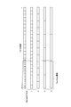
- FIG. 3 is a diagram for explaining a downlink frame structure used in the mobile communication system according to the first embodiment of the present invention.
- FIG. 4 is a diagram for explaining CCE as a minimum unit of resources to be allocated to PDCCH and indexing of “Resource Element Group” in the mobile communication system according to the first embodiment of the present invention.
- FIG. 5 is a diagram for explaining restrictions when allocating resources to PDCCH in the mobile communication system according to the first embodiment of the present invention.
- FIG. 1 is an overall configuration diagram of a mobile communication system according to a first embodiment of the present invention.
- FIG. 2 is a functional block diagram of the radio base station according to the first embodiment of the present invention.
- FIG. 3 is a diagram for explaining a downlink frame structure used in the mobile communication system according to the first embodiment of
- FIG. 6 is a diagram for explaining the size of a search space in which PDCCH decoding is attempted by a mobile station in the mobile communication system according to the first embodiment of the present invention.
- FIG. 7 is a diagram for explaining a search space in which PDCCH decoding is attempted by a mobile station in the mobile communication system according to the first embodiment of the present invention.
- FIG. 8 is a diagram for explaining an example in which PDCCH resource allocation fails in the mobile communication system according to the first embodiment of the present invention.
- FIG. 9 is a diagram for explaining an example in which PDCCH resource allocation fails in the mobile communication system according to the first embodiment of the present invention.
- FIG. 10 is a diagram for explaining a method for avoiding failure of PDCCH resource allocation in the mobile communication system according to the first embodiment of the present invention.
- FIG. 11 is a diagram for explaining a method for avoiding failure of PDCCH resource allocation in the mobile communication system according to the first embodiment of the present invention.
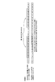
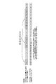
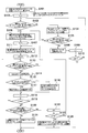
- FIG. 12 is a flowchart showing an operation of the mobile communication system according to the first embodiment of the present invention.
- FIG. 13 is a flowchart showing an operation of the mobile communication system according to the first embodiment of the present invention.
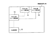
- the mobile communication system according to the present embodiment is an LTE mobile communication system, and includes a radio base station eNB and a mobile station UE. As shown in FIG. 1, in the mobile communication system according to the present embodiment, DCI, CFI, and HI as downlink control information are transmitted via PDCCH, PCFICH, and PHICH as downlink control channels. It is configured.
- the radio base station eNB includes a PCFICH resource allocation unit 11, a PHICH resource allocation unit 12, a CQI acquisition unit 13, and a PDCCH resource allocation unit 14. ing.
- the PCFICH resource allocation unit 11 is configured to allocate PCFICH resources in each cell.
- the PCFICH resource allocation unit 11 uses the PCFICH As a resource, the first OFDM symbol in each subframe is assigned.
- the PCFICH resource allocation unit 11 includes four “Resource Element Groups (resources) as resources for PCFICH within each subframe. Element group) ".
- Resource Element Group is a minimum unit for allocating radio resources to the control channel in the downlink. Specifically, the “Resource Element Group” is composed of four “Resource Elements (resource elements)”.
- the PCFICH resource allocation unit 11 allocates four PCFICH resources that are allocated as resources for the PCFICH so that the system bandwidth is almost equally spaced by calculation using the cell identification information (cell ID) and the system bandwidth. It is configured to select “Resource Element Group”.
- the PHICH resource allocation unit 12 is configured to allocate PHICH resources addressed to the mobile stations UE belonging to each PHICH group.
- the PHICH resource allocation unit 12 is configured to allocate the first OFDM symbol in each subframe as a PHICH resource, as shown in FIG. ing.
- the PHICH resource allocation unit 12 allocates the first 3 OFDM symbols in each subframe as resources for PHICH as shown in FIG. It is configured.
- the PHICH resource allocation unit 12 assigns three “Resource Element Groups” as PHICH resources in each subframe. Configured to assign.
- the PHICH resource allocating unit 12 performs the calculation using the number of “Resource Element Group” excluding the “Resource Element Group” assigned to the PC identification information (cell ID) and the PCFICH. Three “Resource Element Groups” to be allocated as PHICH resources are selected so as to be equally spaced.
- the CQI acquisition unit 13 is configured to acquire the reception quality of the downlink pilot signal notified from the mobile station UE, specifically, the CQI (Channel Quality Indicator).
- the PDCCH resource allocation unit 14 is configured to allocate PDCCH resources addressed to each mobile station.
- the PDCCH resource allocation unit 14 is configured to allocate a maximum of 3 OFDM symbols or 4 OFDM symbols at the beginning of each subframe as a PDCCH resource.
- the number of OFDM symbols is controlled by CFI.
- the PDCCH resource allocation unit 14 uses, as PDCCH resources, Resource element groups that are not allocated as PCFICH and PHICH resources among OFDM symbols allocated for the downlink control channel by the CFI. Configured to assign.
- the PDCCH resource allocation unit 14 is configured to allocate radio resources to each PDCCH in units of “CCE (Control Channel Element, control channel element)”.
- the CCE is a minimum unit for allocating radio resources to the PDCCH, and among the “Resource Element Group” that is not allocated as a resource for the PCFICH and PHICH, a plurality of consecutive “Resource Element Groups”, for example, It is composed of nine consecutive “Resource Element Groups”.
- the “Resource Element Group” that constitutes the CCE is ordered as follows, and nine consecutive “Resource Element Groups” are designated as “CCE”.
- RB is composed of 7 OFDM symbols in the time direction and 12 subcarriers in the frequency direction, and is a minimum unit for allocating radio resources to the data channel.
- Each “Resource Element Group” is configured to be specified by a “Resource Element Group” index (for example, “Resource Element Group” # 0 to # 7).
- the “Resource Element Group” index is assigned according to the following criteria.
- the minimum frequency of the subcarrier corresponding to “Resource Element Group” included in the first “Resource Element Group” is the minimum frequency of the subcarrier corresponding to “Resource Element Group” included in the second “Resource Element Group”.
- the “Resource Element Group” index that identifies the first “Resource Element Group” is smaller than the “Resource Element Group” index that identifies the second “Resource Element Group”.
- the index is allocated from the RB including the “Resource Element” corresponding to the subcarrier of the smallest frequency in the system band.
- Resource Element Group” # 0 to # 8 corresponds to CCE #
- Resource Element Group” # 9 to # 17 corresponds to CCE # 1.
- the PDCCH resource allocation unit 14 determines “Aggregation Level (aggregation level)” indicating how many CCEs are continuously allocated to the PDCCH based on the CQI (reception quality) notified from the mobile station UE. It is configured.
- the PDCCH resource allocation unit 14 is configured to allocate a plurality of continuous CCEs to the PDCCH addressed to the mobile station UE based on the determined “Aggregation Level”.
- CCEs that can be allocated are determined for each “Aggregation Level”.
- the PDCCH resource allocating unit 14 sends only n consecutive CCEs starting from the CCE of the CCE index corresponding to a multiple of n to the mobile station UE. Of PDCCHs.
- the PDCCH resource allocation unit 14 has one continuous CCE starting with CCE # 0, # 1... Corresponding to a multiple of 1. (For example, CCE # 0) can be allocated to the PDCCH addressed to the mobile station UE.
- the PDCCH resource allocating unit 14 has two consecutive CCEs # 0, # 2... Corresponding to a multiple of 2.
- CCEs to be performed (for example, CCE # 0 and CCE # 1) can be assigned to the PDCCH addressed to the mobile station UE.
- the PDCCH resource allocating unit 14 has four consecutive CCEs # 0, # 4... Corresponding to a multiple of 4.
- CCEs to be performed (for example, CCE # 0 to CCE # 3) can be assigned to the PDCCH addressed to the mobile station UE.
- the PDCCH resource allocating unit 14 has eight consecutive CCEs # 0, # 8... Corresponding to a multiple of 8. CCEs to be performed (for example, CCE # 0 to CCE # 7) can be assigned to the PDCCH addressed to the mobile station UE.
- the mobile station UE since the mobile station UE does not know which CCE is assigned to the PDCCH addressed to itself and which “Aggregation Level” is selected, the mobile station UE responds to the PDCCH addressed to itself. Since it is necessary to try decoding the PDCCH for all the CCEs that may be allocated, the mobile station UE can be allocated by providing the CCE restrictions (Tree-based structure) that can be allocated as described above. Can reduce the number of PDCCH decoding attempts.
- the PDCCH resource allocation unit 14 determines, for each mobile station UE, “UE dedicated search space (UE-specific search space, dedicated to the mobile station UE). Search space) ", and CCE may be allocated to the PDCCH addressed to the mobile station UE within the UE-specific search space for each mobile station UE.
- the mobile station UE in the search space, specifically, a “common search space” and individual UEs determined as search spaces dedicated to the mobile station UE. It is configured to attempt to decode PDCCH within the search space.
- the common search space indicates the range of CCE in which all mobile stations UE search for PDCCH (trying to decode PDCCH) within the available radio resources, and the UE individual search space is the available radio resource.
- the range of CCE in which each mobile station UE searches for PDCCH addressed to each mobile station UE (trying to decode PDCCH) is shown.
- the common search space is assigned a PDCCH for a data channel used for common control such as a dynamic broadcast channel D-BCH, a paging channel PCH, and “RACH Response”.
- the common search space is composed of CCE # 0 to CCE # 15, and “Aggregation Level” of the common search space is “4” or “8”.
- uplink scheduling information and downlink scheduling information addressed to the target mobile station UE are allocated to the UE individual search space.
- the common search space and the UE individual search space for a specific mobile station UE may overlap.
- UE individual search spaces for a specific mobile station UE may overlap (for example, UE individual search space for mobile station UE # 1 and UE individual search space for mobile station UE # 5).
- Such a search space differs depending on the type (common search space or UE individual search space) and “Aggregation Level”.
- the size of the search space is a size corresponding to 6 CCEs.
- the number of CCE candidates (one CCE) that can be allocated to the PDCCH in the search space is “6”.
- the size of the search space is a size corresponding to 12 CCEs.
- the number of CCEs (two consecutive CCEs) that can be allocated to the PDCCH is “6”.
- the size of the search space is a size corresponding to 8 CCEs.
- the number of CCEs (four consecutive CCEs) that can be allocated to the PDCCH is “2”.
- the size of the search space is a size corresponding to 16 CCEs.
- the number of CCE (8 consecutive CCE) candidates that can be assigned to the PDCCH is “2”.
- the size of the search space is a size corresponding to 16 CCEs.
- the number of CCE (8 consecutive CCE) candidates assigned to the PDCCH is “2”.
- the size of the search space is a size corresponding to 16 CCEs.
- the number of CCE (4 consecutive CCE) candidates assigned to the PDCCH is “4”.
- the PDCCH resource allocation unit 14 is based on the identification information (UE-ID) of the mobile station UE, the “Aggregation Level” determined for the mobile station UE, and the subframe number in the available radio resource. Thus, the search space dedicated to the mobile station UE may be uniquely determined.
- the PDCCH resource allocating unit 14 applies to the PDCCH addressed to a specific mobile station UE.
- CCE radio resource
- the CCE is assigned to each PDCCH in order, and the PDCCH that assigns the CCE to the nth is denoted as PDCCH # n.
- the PDCCH resource allocation unit 14 changes the “Aggregation Level” when the CCE allocation to the PDCCH addressed to the mobile station UE fails, and based on the changed “Aggregation Level”. A plurality of continuous CCEs are assigned to the PDCCH.
- CCE # 2 to CCE9 and CCE # 13 to CCE # 19 are already assigned in a state where CCE is assigned to PDCCH # n-1, and PDCCH # n
- the PDCCH resource allocation unit 14 cannot allocate CCEs to PDCCH # n.
- the individual search space is changed to CCE # 8 to CCE # 19.
- the PDCCH resource allocation unit 14 can allocate CCE # 10 and CCE # 11 to the PDCCH # n.
- the radio base station eNB may satisfy the required quality based on the CQI notified from the mobile station UE. As possible, the transmission power control in the downlink may be used together.
- the PDCCH resource allocation unit 14 first allocates a CCE in the common search space as a PDCCH resource for transmitting the common DCI, and secondly, it is addressed to the mobile station UE having the highest priority.
- CCEs in the UE dedicated search space are allocated to the PDCCH, and thirdly, CCEs in the UE dedicated search space are sequentially allocated to PDCCHs addressed to other mobile stations UE.
- the PDCCH resource allocation unit 14 selects a CCE for a PDCCH addressed to another mobile station UE from among a plurality of allocation patterns for CCEs for the PDCCH addressed to the mobile station UE having the highest priority.
- the pattern with the smallest number of allocation failures may be adopted, and the CCE may be assigned to the PDCCHs addressed to all the mobile stations UE based on the adopted pattern.
- the PDCCH resource allocation unit 14 is configured to allocate “Resource Element Group” constituting the CCE allocated to the PDCCH addressed to the mobile station UE as a resource for PDCCH addressed to the mobile station UE.
- the radio base station eNB may perform interleaving processing in units of “Resource Element Group” for the resources for PDCCH addressed to the mobile station UE in order to randomize interference.
- step S101 the radio base station eNB allocates a CCE in the common search space as a resource for PDCCH (common channel) for transmitting common DCI.
- PDCCH common channel
- the common search space is composed of CCE # 0 to CCE # 15
- the CCE index of the CCE index is ordered in descending order of PDCCH (for example, PDCCH for D-BCH) in the common channel.
- CCEs in the common search space are assigned in order from the smallest.
- the “Aggregation Level” for the common channel may be set as a fixed value in advance.
- “n” is an index when PDCCHs (UE dedicated channels) for transmitting UE dedicated DCI other than the common DCI are arranged in order of priority.
- the radio base station eNB determines “Aggregation Level” for each UE dedicated channel based on the CQI notified from each mobile station UE.
- the radio base station eNB determines whether there is a CCE that can be allocated to the nth UE dedicated channel in the search space for the nth UE dedicated channel determined based on the “Aggregation Level” described above. Determine whether or not.
- the radio base station eNB Change "Aggregation Level” by one level. In such a case, for example, the radio base station eNB changes “Aggregation Level” from “1”, “2”, “4”, “8” to “2”, “1”, “2”, “4”, respectively. Change to
- the radio base station eNB has a CCE that can be allocated to the n-th UE dedicated channel in the search space for the n-th UE dedicated channel determined based on the changed “Aggregation Level”. It is determined whether or not to do so.
- step S106 If it is determined that it exists, the operation proceeds to step S106, and if it is determined that it does not exist, the operation proceeds to step S108.
- the radio base station eNB sets the nth UE dedicated channel as the highest priority UE dedicated channel (Highest PDCCH).
- CCE # m is a CCE candidate that can be allocated to the nth UE dedicated channel in the search space for the nth UE dedicated channel.
- the radio base station eNB stops transmission of the nth UE dedicated channel in step S108.
- step S109 the radio base station eNB increases “n” by “1”, that is, the UE dedicated channel with the next highest priority is assigned to the UE dedicated channel with the highest priority (the nth UE dedicated channel).
- step S110 the radio base station eNB determines whether “n ⁇ N” is satisfied. When it is determined that “n ⁇ N” is satisfied, the operation returns to step S103, and when it is determined that “n ⁇ N” is not satisfied, the operation ends.
- the radio base station eNB has a CCE that can be allocated to the u-th UE dedicated channel in the search space for the u-th UE dedicated channel determined based on the “Aggregation Level” described above. It is determined whether or not to do so.
- step S116 If it is determined that it exists, the operation proceeds to step S116, and if it is determined that it does not exist, the operation proceeds to step S114.
- step S114 the radio base station eNB changes the above-mentioned “Aggregation Level”.
- the radio base station eNB may change the “Aggregation Level” to one smaller value. However, when the “Aggregation Level” is “1”, the radio base station eNB may change the “Aggregation Level” to “2”.
- the radio base station eNB may change the “Aggregation Level” to one larger value. However, when the “Aggregation Level” is “8”, the radio base station eNB may change the “Aggregation Level” to “4”.
- the radio base station eNB changes the “Aggregation Level” to a value larger than the initial value of “Aggregation Level”, there is a CCE that can be allocated to the u-th UE dedicated channel.
- the “Aggregation Level” may be changed to a value that is one smaller than the initial value of “Aggregation Level”.
- the radio base station eNB changes the “Aggregation Level” to a value that is one smaller than the initial value of “Aggregation Level”, and then there is a CCE that can be allocated to the u-th UE dedicated channel. When it is determined not to do so, the “Aggregation Level” may be changed to a value larger than the initial value of “Aggregation Level”.
- the radio base station eNB has a CCE that can be allocated to the u-th UE dedicated channel in the search space for the u-th UE dedicated channel determined based on the changed “Aggregation Level”. It is determined whether or not to do so.
- step S116 If it is determined that it exists, the operation proceeds to step S116, and if it is determined that it does not exist, the operation proceeds to step S117. Note that step S114 and step S115 may be omitted.
- step S116 the radio base station eNB selects the CCE having the smallest CCE index among the CCEs that can be allocated to the u-th UE dedicated channel in the search space for the u-th UE dedicated channel. Assign to individual channels.
- step S117 the radio base station eNB stops transmission of the u-th UE dedicated channel, increases “u” by “1” in step S118, and satisfies “u ⁇ N” in step S119. Determine whether or not.
- step S113 If it is determined that “u ⁇ N” is satisfied, the operation returns to step S113. If it is determined that “u ⁇ N” is not satisfied, the operation proceeds to step S120.
- the radio base station eNB has a UE dedicated channel (PDCCH in which CCE allocation has failed) among the nth and subsequent UE dedicated channels (PDCCH addressed to other mobile stations UE). It is determined whether or not to do so.
- PDCCH UE dedicated channel
- step S121 If it is determined that it does not exist, the operation proceeds to step S121. If it is determined that it exists, the operation proceeds to step S122.
- step S121 the radio base station eNB sets the current CCE allocation pattern for the UE dedicated channel as the CCE allocation pattern for the UE dedicated channel in the subframe.
- the radio base station eNB increases “m” by “1” in step S122, and determines whether “m ⁇ M” is satisfied in step S119.
- step S111 If it is determined that “m ⁇ M” is satisfied, the operation returns to step S111. If it is determined that “m ⁇ M” is not satisfied, the operation proceeds to step S124.
- the radio base station eNB selects an allocation pattern with the smallest number of UE dedicated channels (PDCCHs for which CCE allocation has failed) from among CCE allocation patterns for M UE dedicated channels.
- the CCE allocation pattern for the UE dedicated channel in the subframe is used.
- the radio base station eNB determines the CCE allocation pattern for the UE dedicated channel in the subframe in consideration of the priority of each UE dedicated channel among the CCE allocation patterns for the M UE dedicated channels. May be.
- the radio base station eNB may stop the transmission among the plurality of allocation patterns.
- the allocation pattern with the lowest priority of the UE dedicated channel with the highest priority among the dedicated channels may be used as the CCE allocation pattern for the UE dedicated channel in the subframe.
- an operation example 2 of the mobile communication system according to the first embodiment of the present invention will be described.
- the operation example 2 of the mobile communication system according to the present embodiment will be described by focusing on differences from the operation example 1 of the mobile communication system according to the above-described embodiment.
- step S201 the radio base station eNB allocates a CCE in the common search space as a resource for the common channel.
- “n” is an index when UE dedicated channels are arranged in order of priority.
- the radio base station eNB determines “Aggregation Level” for each UE dedicated channel based on the CQI notified from each mobile station UE.
- the radio base station eNB determines whether there is a CCE that can be allocated to the nth UE dedicated channel in the search space for the nth UE dedicated channel determined based on the “Aggregation Level” described above. Determine whether or not.
- the radio base station eNB changes the above-mentioned “Aggregation Level” by one step in step S204. In such a case, for example, the radio base station eNB changes “Aggregation Level” from “1”, “2”, “4”, “8” to “2”, “1”, “2”, “4”, respectively. Change to
- the radio base station eNB has a CCE that can be allocated to the nth UE dedicated channel in the search space for the nth UE dedicated channel determined based on the changed “Aggregation Level”. It is determined whether or not to do so.
- step S206 If it is determined that it exists, the operation proceeds to step S206, and if it is determined that it does not exist, the operation proceeds to step S208.
- the radio base station eNB sets the nth UE dedicated channel as the highest priority UE dedicated channel (Highest PDCCH), and in step S207, determines the nth UE determined based on the above-mentioned “Aggregation Level”.
- the CCE having the smallest CCE index is allocated to the nth UE dedicated channel.
- the radio base station eNB stops transmission of the nth UE dedicated channel in step S208.
- step S209 the radio base station eNB increases “n” by “1”, that is, the UE dedicated channel with the next highest priority is assigned to the UE dedicated channel with the highest priority (the nth UE dedicated channel).
- step S210 the radio base station eNB determines whether “n ⁇ N” is satisfied. When it is determined that “n ⁇ N” is satisfied, the operation returns to step S203, and when it is determined that “n ⁇ N” is not satisfied, the operation ends.
- step S213 the radio base station eNB changes the above-mentioned “Aggregation Level”.
- the radio base station eNB may change the “Aggregation Level” to one smaller value. However, when the “Aggregation Level” is “1”, the radio base station eNB changes the “Aggregation Level” to “2”.
- the radio base station eNB has a CCE that can be allocated to the u-th UE dedicated channel in the search space for the u-th UE dedicated channel determined based on the changed “Aggregation Level”. It is determined whether or not to do so.
- step S215 If it is determined that it exists, the operation proceeds to step S215, and if it is determined that it does not exist, the operation proceeds to step S216.
- the radio base station eNB selects the CCE having the smallest CCE index from among CCEs that can be allocated to the u th UE dedicated channel in the search space for the u th UE dedicated channel. Assign to individual channels.
- step S216 the radio base station eNB stops transmission of the u-th UE dedicated channel.
- step S217 “u” is increased by “1”.
- step S218, “u ⁇ N” is satisfied. Determine whether or not.
- step S212 If it is determined that “u ⁇ N” is satisfied, the operation returns to step S212. If it is determined that “u ⁇ N” is not satisfied, the operation proceeds to step S219.
- the radio base station eNB has a UE dedicated channel (PDCCH in which CCE allocation has failed) among the nth and subsequent UE dedicated channels (PDCCH addressed to other mobile stations UE). It is determined whether or not to do so.
- PDCCH UE dedicated channel
- step S220 If it is determined that it does not exist, the operation proceeds to step S220, and if it is determined that it exists, the operation proceeds to step S221.
- step S220 the radio base station eNB sets the CCE allocation pattern for the UE dedicated channel this time as the CCE allocation pattern for the UE dedicated channel in the subframe.
- the radio base station eNB determines whether “k ⁇ 1” is established in step S221.
- step S22 If it is determined that “k ⁇ 1” is satisfied, the operation proceeds to step S223. If it is determined that “k ⁇ 1” is not satisfied, the operation proceeds to step S222.
- the radio base station eNB selects an allocation pattern with the smallest number of UE dedicated channels (PDCCHs for which CCE allocation has failed) from among CCE allocation patterns for M UE dedicated channels.
- the CCE allocation pattern for the UE dedicated channel in the subframe is used.
- the radio base station eNB determines the CCE allocation pattern for the UE dedicated channel in the subframe in consideration of the priority of each UE dedicated channel among the CCE allocation patterns for the M UE dedicated channels. May be.
- the radio base station eNB among the CCEs that can be allocated to the nth UE dedicated channel in the search space for the nth UE dedicated channel determined based on the above-mentioned “Aggregation Level” in Step S223, The CCE having the largest CCE index (candidate index) is allocated to the nth UE dedicated channel.
- “k” is increased by “1”.
- the radio base station eNB may limit the CCE allocation pattern candidates for the UE dedicated channel in the subframe.
- the radio base station eNB determines the CCE allocated to the highest priority UE dedicated channel (nth UE dedicated channel). Candidates may be limited to the CCE of the youngest CCE index and the oldest CCE index.
- the CCE allocation pattern candidate for the UE dedicated channel in the subframe is selected from among CCE # 2, CCE # 3, CCE # 10, and CCE # 11 as the highest priority UE. You may limit to two allocation patterns allocated with respect to an individual channel.
- the mobile communication system it is not necessary to try a combination of CCE assignments for all “Aggregation Levels” and all PDCCHs, and therefore, the UE dedicated channel in the subframe The CCE allocation pattern for can be efficiently searched.
- a first feature of the present embodiment is a radio base station eNB configured to allocate a CCE composed of a plurality of continuous “Resource Element Groups” in usable radio resources to a PDCCH, Based on the CQI notified from the mobile station UE, it is configured to determine “Aggregation Level” indicating how many CCEs are continuously allocated to the PDCCH, and based on the determined “Aggregation Level” And a plurality of continuous CCEs are allocated to the PDCCH addressed to the mobile station UE, and “Resource Element Group” constituting the allocated CCE is allocated as a resource for the PDCCH addressed to the mobile station UE.
- the PDCCH resource allocation unit 14 is configured based on the changed “Aggregation Level” when the CCE allocation to the PDCCH addressed to the mobile station UE fails.
- the gist of the invention is that a plurality of continuous CCEs are allocated to the PDCCH addressed to the mobile station UE.
- the search space dedicated to the mobile station UE indicates a CCE range in which each mobile station UE searches for a PDCCH addressed to each mobile station UE within an available radio resource.
- the resource allocation unit 14 may be configured to determine a search space dedicated to the mobile station UE and allocate a CCE to the PDCCH addressed to the mobile station UE within the search space dedicated to the mobile station UE.
- the PDCCH resource allocation unit 14 includes the identification information of the mobile station UE, the “Aggregation Level” determined for the mobile station UE, and the subframe number in the available radio resource. Based on the above, the search space dedicated to the mobile station UE may be determined.
- the PDCCH resource allocation unit 14 sequentially allocates CCEs to PDCCHs addressed to other mobile stations UE after allocation of CCEs to the PDCCHs addressed to the mobile station UE having the highest priority.
- the PDCCH resource allocating unit 14 is configured to perform CCE for PDCCH addressed to other mobile stations UE from among a plurality of allocation patterns for CCEs for PDCCH addressed to the mobile station UE having the highest priority. The pattern with the smallest number of allocation failures may be adopted, and the CCE may be assigned to the PDCCHs addressed to all the mobile stations UE based on the adopted pattern.
- the operations of the mobile station UE and the radio base station eNB described above may be implemented by hardware, may be implemented by a software module executed by a processor, or may be implemented by a combination of both. .
- Software modules include RAM (RandomMSCess Memory), flash memory, ROM (Read Only Memory), EPROM (Erasable Programmable ROM), EEPROM (Electronically Erasable and Programmable, Disk, and Hard Disk), Or in any type of storage medium such as a CD-ROM.
- the storage medium is connected to the processor so that the processor can read and write information from and to the storage medium. Further, such a storage medium may be integrated in the processor. Further, such a storage medium and a processor may be provided in the ASIC. Such an ASIC may be provided in the mobile station UE or the radio base station eNB. Further, the storage medium and the processor may be provided as a discrete component in the mobile station UE or the radio base station eNB.
Landscapes
- Engineering & Computer Science (AREA)
- Signal Processing (AREA)
- Computer Networks & Wireless Communication (AREA)
- Quality & Reliability (AREA)
- Mobile Radio Communication Systems (AREA)
Abstract
Description
図1乃至図11を参照して、本発明の第1の実施形態に係る移動通信システムの構成について説明する。
図12乃至図13を参照して、本発明の第1の実施形態に係る移動通信システムの動作について説明する。
本発明の第1の実施形態に係る移動通信システムによれば、UE個別DCIを送信するためのPDCCHに対するCCEの割り当てに失敗した場合には、「Aggregation Level」を変更して、再度、UE個別DCIを送信するためのPDCCHに対するCCEの割り当てを行うことができる。
Claims (4)
- 物理下りリンク制御チャネルに対して、使用可能な無線リソース内の連続する複数のリソース要素グループからなる制御チャネル要素を割り当てるように構成されている無線基地局であって、
移動局から通知された受信品質に基づいて、前記物理下りリンク制御チャネルに対して前記制御チャネル要素を何個連続で割り当てるかを示す集約レベルを決定するように構成されている集約レベル決定部と、
決定された前記集約レベルに基づいて、前記移動局宛ての物理下りリンク制御チャネルに対して、連続する複数の制御チャネル要素を割り当てるように構成されている制御チャネル要素割当部と、
割り当てられた前記制御チャネル要素を構成するリソース要素グループを、前記移動局宛ての物理下りリンク制御チャネル用のリソースとして割り当てるように構成されているリソース割当部とを具備し、
前記制御チャネル要素割当部は、前記移動局宛ての物理下りリンク制御チャネルに対する制御チャネル要素の割り当てに失敗した場合には、前記集約レベル決定部によって変更された集約レベルに基づいて、前記移動局宛ての物理下りリンク制御チャネルに対して、連続する複数の制御チャネル要素を割り当てるように構成されていることを特徴とする無線基地局。 - 移動局専用の探索空間は、前記使用可能な無線リソース内で、各移動局が各移動局宛ての物理下りリンク制御チャネルを探索する制御チャネル要素の範囲を示し、
前記制御チャネル要素割当部は、前記移動局専用の探索空間を決定し、該移動局専用の探索空間内で、該移動局宛ての物理下りリンク制御チャネルに対して、前記制御チャネル要素を割り当てるように構成されていることを特徴とする請求項1に記載の無線基地局。 - 前記制御チャネル要素割当部は、前記移動局の識別情報と、該移動局に対して決定された前記集約レベルと、前記使用可能な無線リソースにおけるサブフレーム番号とに基づいて、該移動局専用の探索空間を決定するように構成されていることを特徴とする請求項2に記載の無線基地局。
- 前記制御チャネル要素割当部は、最も優先度が高い移動局宛ての物理下りリンク制御チャネルに対する制御チャネル要素の割り当ての後、他の移動局宛ての物理下りリンク制御チャネルに対する制御チャネル要素の割り当てを順次行うように構成されており、
前記制御チャネル要素割当部は、前記最も優先度が高い移動局宛ての物理下りリンク制御チャネルに対する制御チャネル要素についての複数の割り当てパターンの中から、前記他の移動局宛ての物理下りリンク制御チャネルに対する制御チャネル要素の割り当てに失敗する数が最も少ないパターンを採用し、採用したパターンに基づいて、全ての移動局宛ての物理下りリンク制御チャネルに対する制御チャネル要素の割り当てを行うように構成されていることを特徴とする請求項1に記載の無線基地局。
Priority Applications (3)
| Application Number | Priority Date | Filing Date | Title |
|---|---|---|---|
| US13/128,071 US8565254B2 (en) | 2008-11-07 | 2009-11-06 | Radio base station |
| EP09824844.6A EP2355604B1 (en) | 2008-11-07 | 2009-11-06 | Wireless base station |
| CN200980144413.4A CN102210181B (zh) | 2008-11-07 | 2009-11-06 | 无线基站 |
Applications Claiming Priority (2)
| Application Number | Priority Date | Filing Date | Title |
|---|---|---|---|
| JP2008287093A JP5162416B2 (ja) | 2008-11-07 | 2008-11-07 | 無線基地局 |
| JP2008-287093 | 2008-11-07 |
Publications (2)
| Publication Number | Publication Date |
|---|---|
| WO2010053145A1 true WO2010053145A1 (ja) | 2010-05-14 |
| WO2010053145A9 WO2010053145A9 (ja) | 2011-04-21 |
Family
ID=42152952
Family Applications (1)
| Application Number | Title | Priority Date | Filing Date |
|---|---|---|---|
| PCT/JP2009/068957 WO2010053145A1 (ja) | 2008-11-07 | 2009-11-06 | 無線基地局 |
Country Status (5)
| Country | Link |
|---|---|
| US (1) | US8565254B2 (ja) |
| EP (1) | EP2355604B1 (ja) |
| JP (1) | JP5162416B2 (ja) |
| CN (1) | CN102210181B (ja) |
| WO (1) | WO2010053145A1 (ja) |
Cited By (5)
| Publication number | Priority date | Publication date | Assignee | Title |
|---|---|---|---|---|
| WO2012062178A1 (zh) * | 2010-11-08 | 2012-05-18 | 中兴通讯股份有限公司 | 用于确定中继链路资源单元组的方法及装置 |
| WO2012121636A1 (en) * | 2011-03-08 | 2012-09-13 | Telefonaktiebolaget L M Ericsson (Publ) | Methods and network nodes for allocating control channel elements for physical downlink control channel |
| WO2014000306A1 (zh) * | 2012-06-30 | 2014-01-03 | 华为技术有限公司 | 传输形式确定方法及终端、基站 |
| JP2014517590A (ja) * | 2011-05-09 | 2014-07-17 | エンパイア テクノロジー ディベロップメント エルエルシー | Lteシステムにおける制御チャネルのパワー制御 |
| US20140314040A1 (en) * | 2011-11-15 | 2014-10-23 | Optis Cellular Technology, Llc | Control channel element allocation apparatus and method |
Families Citing this family (27)
| Publication number | Priority date | Publication date | Assignee | Title |
|---|---|---|---|---|
| KR101789325B1 (ko) * | 2009-05-14 | 2017-10-24 | 엘지전자 주식회사 | 다중 반송파 시스템에서 제어채널을 모니터링하는 장치 및 방법 |
| JP5459096B2 (ja) * | 2010-06-21 | 2014-04-02 | 富士通株式会社 | 移動通信システムの制御チャネル割り当て方法及び基地局装置 |
| US9049709B2 (en) | 2010-07-21 | 2015-06-02 | Panasonic Intellectual Property Corporation Of America | Base station device, terminal device, transmission method, and reception method |
| CN102404857B (zh) * | 2010-09-10 | 2014-07-16 | 中兴通讯股份有限公司 | Lte下行控制信道资源分配方法及基站 |
| EP2670192A4 (en) | 2011-01-28 | 2016-08-17 | Fujitsu Ltd | WIRELESS COMMUNICATION DEVICE, WIRELESS COMMUNICATION SYSTEM, AND WIRELESS COMMUNICATION METHOD |
| KR101217614B1 (ko) * | 2011-05-31 | 2013-01-02 | 한국항공대학교산학협력단 | 공간 분할 다중 접속 이동 통신 시스템에서 제어 채널 스케쥴링 방법 및 장치 |
| US8811207B2 (en) * | 2011-10-28 | 2014-08-19 | Nokia Corporation | Allocating control data to user equipment |
| IN2014KN01182A (ja) * | 2011-11-04 | 2015-10-16 | Ericsson Telefon Ab L M | |
| JP6219018B2 (ja) * | 2012-01-30 | 2017-10-25 | 株式会社Nttドコモ | 無線基地局装置、ユーザ端末、無線通信システム及び無線通信方法 |
| EP2820902A4 (en) * | 2012-03-02 | 2015-10-14 | Nokia Technologies Oy | PUCCH RESOURCE MANAGEMENT MECHANISM FOR COORDINATED MULTI-POINT OPERATION |
| US9338773B2 (en) * | 2012-03-26 | 2016-05-10 | Qualcomm Incorporated | Common search space for EPDCCH in LTE |
| KR20130111999A (ko) * | 2012-04-02 | 2013-10-11 | 엘지전자 주식회사 | 무선 통신 시스템에서 분산적 타입 하향링크 제어 채널의 검색 영역을 위하여 자원 블록을 구성하는 방법 및 이를 위한 장치 |
| CN103582031B (zh) * | 2012-07-20 | 2016-09-07 | 中国移动通信集团公司 | 一种物理下行控制信道资源分配方法及设备 |
| MX2014000701A (es) | 2012-07-25 | 2014-03-06 | Panasonic Corp | Aparato de estacion base, aparato terminal, metodo de transmision y metodo de recepcion. |
| WO2014019146A1 (zh) * | 2012-07-31 | 2014-02-06 | 华为技术有限公司 | 控制信道传输方法及基站、终端 |
| WO2014019234A1 (zh) * | 2012-08-03 | 2014-02-06 | 华为技术有限公司 | 控制信息发送方法、接收方法和装置 |
| CN104662827B (zh) | 2012-09-21 | 2017-11-14 | Lg电子株式会社 | 在无线通信系统中接收或发送下行链路控制信号的方法和装置 |
| US9161342B2 (en) * | 2012-09-28 | 2015-10-13 | Alcatel Lucent | Methods and apparatuses for allocating wireless resources in wireless network |
| CN104718714B (zh) * | 2012-10-14 | 2018-02-02 | Lg电子株式会社 | 在无线通信系统中在用户设备发送用于epdcch应答方法和设备 |
| EP2916608B1 (en) * | 2012-11-01 | 2017-12-06 | Sharp Kabushiki Kaisha | Mobile station apparatus, base station apparatus, communication method and integrated circuit |
| MX360549B (es) * | 2012-11-02 | 2018-10-26 | Huawei Tech Co Ltd | Método para asignar número de candidatos de canal de control y número de tiempos de detección ciega, estación base y equipo de usuario. |
| US9635659B2 (en) | 2013-01-03 | 2017-04-25 | Qualcomm Incorporated | ENB PDCCH implementation to avoid ambiguous DCI information |
| RU2608767C1 (ru) | 2013-01-18 | 2017-01-24 | Хуавей Текнолоджиз Ко., Лтд. | Способ определения epdcch кандидата и устройство |
| US9660751B2 (en) * | 2015-02-17 | 2017-05-23 | Freescale Semiconductor, Inc. | Wireless communication system with efficient PDCCH processing |
| WO2017184039A1 (en) * | 2016-04-19 | 2017-10-26 | Telefonaktiebolaget Lm Ericsson (Publ) | Applying more robust transmission procedure |
| CN113037432A (zh) * | 2017-09-08 | 2021-06-25 | 华为技术有限公司 | 通信方法、终端设备和网络设备 |
| US11153862B2 (en) * | 2018-03-22 | 2021-10-19 | Apple Inc. | Physical downlink control channel (PDCCH) blind decoding in fifth generation (5G) new radio (NR) systems |
Citations (2)
| Publication number | Priority date | Publication date | Assignee | Title |
|---|---|---|---|---|
| WO2008114541A1 (ja) * | 2007-03-20 | 2008-09-25 | Mitsubishi Electric Corporation | 無線通信システム、基地局、端末装置、及び無線通信方法 |
| WO2008129810A1 (ja) * | 2007-03-23 | 2008-10-30 | Panasonic Corporation | 無線通信基地局装置および制御チャネル配置方法 |
Family Cites Families (5)
| Publication number | Priority date | Publication date | Assignee | Title |
|---|---|---|---|---|
| CN100566229C (zh) * | 2005-07-13 | 2009-12-02 | 大唐移动通信设备有限公司 | 多载波通信系统的无线资源分配方法 |
| CN101132229A (zh) * | 2006-08-21 | 2008-02-27 | 北京三星通信技术研究有限公司 | 下行共享控制信道的传输方法及设备 |
| KR101505687B1 (ko) * | 2007-11-05 | 2015-03-31 | 엘지전자 주식회사 | 무선통신 시스템에서 전력제어 방법 |
| KR100943908B1 (ko) * | 2008-02-19 | 2010-02-24 | 엘지전자 주식회사 | Pdcch를 통한 제어 정보 송수신 방법 |
| CN101252783B (zh) * | 2008-03-27 | 2012-09-05 | 中兴通讯股份有限公司 | 一种资源分配方法 |
-
2008
- 2008-11-07 JP JP2008287093A patent/JP5162416B2/ja active Active
-
2009
- 2009-11-06 EP EP09824844.6A patent/EP2355604B1/en active Active
- 2009-11-06 WO PCT/JP2009/068957 patent/WO2010053145A1/ja active Application Filing
- 2009-11-06 US US13/128,071 patent/US8565254B2/en not_active Expired - Fee Related
- 2009-11-06 CN CN200980144413.4A patent/CN102210181B/zh not_active Expired - Fee Related
Patent Citations (2)
| Publication number | Priority date | Publication date | Assignee | Title |
|---|---|---|---|---|
| WO2008114541A1 (ja) * | 2007-03-20 | 2008-09-25 | Mitsubishi Electric Corporation | 無線通信システム、基地局、端末装置、及び無線通信方法 |
| WO2008129810A1 (ja) * | 2007-03-23 | 2008-10-30 | Panasonic Corporation | 無線通信基地局装置および制御チャネル配置方法 |
Non-Patent Citations (1)
| Title |
|---|
| See also references of EP2355604A4 * |
Cited By (9)
| Publication number | Priority date | Publication date | Assignee | Title |
|---|---|---|---|---|
| WO2012062178A1 (zh) * | 2010-11-08 | 2012-05-18 | 中兴通讯股份有限公司 | 用于确定中继链路资源单元组的方法及装置 |
| US9491757B2 (en) | 2010-11-08 | 2016-11-08 | Zte Corporation | Method and apparatus for determining relay link resource element group |
| WO2012121636A1 (en) * | 2011-03-08 | 2012-09-13 | Telefonaktiebolaget L M Ericsson (Publ) | Methods and network nodes for allocating control channel elements for physical downlink control channel |
| CN103430473A (zh) * | 2011-03-08 | 2013-12-04 | 瑞典爱立信有限公司 | 分配用于物理下行链路控制信道的控制信道元素的方法和网络节点 |
| CN103430473B (zh) * | 2011-03-08 | 2016-10-12 | 瑞典爱立信有限公司 | 分配用于物理下行链路控制信道的控制信道元素的方法和网络节点 |
| JP2014517590A (ja) * | 2011-05-09 | 2014-07-17 | エンパイア テクノロジー ディベロップメント エルエルシー | Lteシステムにおける制御チャネルのパワー制御 |
| US8958839B2 (en) | 2011-05-09 | 2015-02-17 | Empire Technology Development Llc | Power control of control channels in an LTE system |
| US20140314040A1 (en) * | 2011-11-15 | 2014-10-23 | Optis Cellular Technology, Llc | Control channel element allocation apparatus and method |
| WO2014000306A1 (zh) * | 2012-06-30 | 2014-01-03 | 华为技术有限公司 | 传输形式确定方法及终端、基站 |
Also Published As
| Publication number | Publication date |
|---|---|
| WO2010053145A9 (ja) | 2011-04-21 |
| US8565254B2 (en) | 2013-10-22 |
| EP2355604A1 (en) | 2011-08-10 |
| EP2355604A4 (en) | 2013-05-29 |
| US20110310817A1 (en) | 2011-12-22 |
| JP5162416B2 (ja) | 2013-03-13 |
| CN102210181B (zh) | 2014-04-09 |
| JP2010114780A (ja) | 2010-05-20 |
| EP2355604B1 (en) | 2017-09-27 |
| CN102210181A (zh) | 2011-10-05 |
Similar Documents
| Publication | Publication Date | Title |
|---|---|---|
| JP5162416B2 (ja) | 無線基地局 | |
| US20220386344A1 (en) | Extending physical downlink control channels | |
| US20170127391A1 (en) | Allocating a control channel for carrier aggregation | |
| KR102033442B1 (ko) | 공통 검색 공간 및 ue 특정 검색 공간을 블라인드 검출하기 위한 방법 및 장치 | |
| US11683788B2 (en) | System and method for data channel transmission and reception | |
| EP3447958B1 (en) | Epdcch search space design | |
| EP3651521B1 (en) | Detecting method and apparatus for common control channel | |
| KR101767021B1 (ko) | 물리적 다운링크 제어 채널의 검색 공간의 매핑 방법 및 장치 | |
| KR102084923B1 (ko) | 통신 장치, 통신 방법 및 집적 회로 | |
| CN113016220B (zh) | 数字无线通信的方法、系统和设备 | |
| CN111556571B (zh) | 传输调度信息的方法和装置 | |
| RU2638544C2 (ru) | Способ и устройство для отображения ресурсов физического канала управления нисходящей линии связи |
Legal Events
| Date | Code | Title | Description |
|---|---|---|---|
| WWE | Wipo information: entry into national phase |
Ref document number: 200980144413.4 Country of ref document: CN |
|
| 121 | Ep: the epo has been informed by wipo that ep was designated in this application |
Ref document number: 09824844 Country of ref document: EP Kind code of ref document: A1 |
|
| NENP | Non-entry into the national phase |
Ref country code: DE |
|
| WWE | Wipo information: entry into national phase |
Ref document number: 2011/KOLNP/2011 Country of ref document: IN |
|
| REEP | Request for entry into the european phase |
Ref document number: 2009824844 Country of ref document: EP |
|
| WWE | Wipo information: entry into national phase |
Ref document number: 2009824844 Country of ref document: EP |
|
| WWE | Wipo information: entry into national phase |
Ref document number: 13128071 Country of ref document: US |