WO2010052766A1 - Hybrid vehicle and hybrid vehicle control method - Google Patents
Hybrid vehicle and hybrid vehicle control method Download PDFInfo
- Publication number
- WO2010052766A1 WO2010052766A1 PCT/JP2008/070092 JP2008070092W WO2010052766A1 WO 2010052766 A1 WO2010052766 A1 WO 2010052766A1 JP 2008070092 W JP2008070092 W JP 2008070092W WO 2010052766 A1 WO2010052766 A1 WO 2010052766A1
- Authority
- WO
- WIPO (PCT)
- Prior art keywords
- power
- charge
- storage unit
- power storage
- control
- Prior art date
Links
Images


Classifications
-
- H—ELECTRICITY
- H02—GENERATION; CONVERSION OR DISTRIBUTION OF ELECTRIC POWER
- H02J—CIRCUIT ARRANGEMENTS OR SYSTEMS FOR SUPPLYING OR DISTRIBUTING ELECTRIC POWER; SYSTEMS FOR STORING ELECTRIC ENERGY
- H02J7/00—Circuit arrangements for charging or depolarising batteries or for supplying loads from batteries
- H02J7/007—Regulation of charging or discharging current or voltage
- H02J7/007188—Regulation of charging or discharging current or voltage the charge cycle being controlled or terminated in response to non-electric parameters
- H02J7/007192—Regulation of charging or discharging current or voltage the charge cycle being controlled or terminated in response to non-electric parameters in response to temperature
- H02J7/007194—Regulation of charging or discharging current or voltage the charge cycle being controlled or terminated in response to non-electric parameters in response to temperature of the battery
-
- B—PERFORMING OPERATIONS; TRANSPORTING
- B60—VEHICLES IN GENERAL
- B60L—PROPULSION OF ELECTRICALLY-PROPELLED VEHICLES; SUPPLYING ELECTRIC POWER FOR AUXILIARY EQUIPMENT OF ELECTRICALLY-PROPELLED VEHICLES; ELECTRODYNAMIC BRAKE SYSTEMS FOR VEHICLES IN GENERAL; MAGNETIC SUSPENSION OR LEVITATION FOR VEHICLES; MONITORING OPERATING VARIABLES OF ELECTRICALLY-PROPELLED VEHICLES; ELECTRIC SAFETY DEVICES FOR ELECTRICALLY-PROPELLED VEHICLES
- B60L58/00—Methods or circuit arrangements for monitoring or controlling batteries or fuel cells, specially adapted for electric vehicles
- B60L58/10—Methods or circuit arrangements for monitoring or controlling batteries or fuel cells, specially adapted for electric vehicles for monitoring or controlling batteries
- B60L58/12—Methods or circuit arrangements for monitoring or controlling batteries or fuel cells, specially adapted for electric vehicles for monitoring or controlling batteries responding to state of charge [SoC]
- B60L58/15—Preventing overcharging
-
- B—PERFORMING OPERATIONS; TRANSPORTING
- B60—VEHICLES IN GENERAL
- B60L—PROPULSION OF ELECTRICALLY-PROPELLED VEHICLES; SUPPLYING ELECTRIC POWER FOR AUXILIARY EQUIPMENT OF ELECTRICALLY-PROPELLED VEHICLES; ELECTRODYNAMIC BRAKE SYSTEMS FOR VEHICLES IN GENERAL; MAGNETIC SUSPENSION OR LEVITATION FOR VEHICLES; MONITORING OPERATING VARIABLES OF ELECTRICALLY-PROPELLED VEHICLES; ELECTRIC SAFETY DEVICES FOR ELECTRICALLY-PROPELLED VEHICLES
- B60L58/00—Methods or circuit arrangements for monitoring or controlling batteries or fuel cells, specially adapted for electric vehicles
- B60L58/10—Methods or circuit arrangements for monitoring or controlling batteries or fuel cells, specially adapted for electric vehicles for monitoring or controlling batteries
- B60L58/24—Methods or circuit arrangements for monitoring or controlling batteries or fuel cells, specially adapted for electric vehicles for monitoring or controlling batteries for controlling the temperature of batteries
- B60L58/25—Methods or circuit arrangements for monitoring or controlling batteries or fuel cells, specially adapted for electric vehicles for monitoring or controlling batteries for controlling the temperature of batteries by controlling the electric load
-
- B—PERFORMING OPERATIONS; TRANSPORTING
- B60—VEHICLES IN GENERAL
- B60W—CONJOINT CONTROL OF VEHICLE SUB-UNITS OF DIFFERENT TYPE OR DIFFERENT FUNCTION; CONTROL SYSTEMS SPECIALLY ADAPTED FOR HYBRID VEHICLES; ROAD VEHICLE DRIVE CONTROL SYSTEMS FOR PURPOSES NOT RELATED TO THE CONTROL OF A PARTICULAR SUB-UNIT
- B60W10/00—Conjoint control of vehicle sub-units of different type or different function
- B60W10/04—Conjoint control of vehicle sub-units of different type or different function including control of propulsion units
- B60W10/06—Conjoint control of vehicle sub-units of different type or different function including control of propulsion units including control of combustion engines
-
- B—PERFORMING OPERATIONS; TRANSPORTING
- B60—VEHICLES IN GENERAL
- B60W—CONJOINT CONTROL OF VEHICLE SUB-UNITS OF DIFFERENT TYPE OR DIFFERENT FUNCTION; CONTROL SYSTEMS SPECIALLY ADAPTED FOR HYBRID VEHICLES; ROAD VEHICLE DRIVE CONTROL SYSTEMS FOR PURPOSES NOT RELATED TO THE CONTROL OF A PARTICULAR SUB-UNIT
- B60W10/00—Conjoint control of vehicle sub-units of different type or different function
- B60W10/04—Conjoint control of vehicle sub-units of different type or different function including control of propulsion units
- B60W10/08—Conjoint control of vehicle sub-units of different type or different function including control of propulsion units including control of electric propulsion units, e.g. motors or generators
-
- B—PERFORMING OPERATIONS; TRANSPORTING
- B60—VEHICLES IN GENERAL
- B60W—CONJOINT CONTROL OF VEHICLE SUB-UNITS OF DIFFERENT TYPE OR DIFFERENT FUNCTION; CONTROL SYSTEMS SPECIALLY ADAPTED FOR HYBRID VEHICLES; ROAD VEHICLE DRIVE CONTROL SYSTEMS FOR PURPOSES NOT RELATED TO THE CONTROL OF A PARTICULAR SUB-UNIT
- B60W10/00—Conjoint control of vehicle sub-units of different type or different function
- B60W10/24—Conjoint control of vehicle sub-units of different type or different function including control of energy storage means
- B60W10/26—Conjoint control of vehicle sub-units of different type or different function including control of energy storage means for electrical energy, e.g. batteries or capacitors
-
- B—PERFORMING OPERATIONS; TRANSPORTING
- B60—VEHICLES IN GENERAL
- B60W—CONJOINT CONTROL OF VEHICLE SUB-UNITS OF DIFFERENT TYPE OR DIFFERENT FUNCTION; CONTROL SYSTEMS SPECIALLY ADAPTED FOR HYBRID VEHICLES; ROAD VEHICLE DRIVE CONTROL SYSTEMS FOR PURPOSES NOT RELATED TO THE CONTROL OF A PARTICULAR SUB-UNIT
- B60W20/00—Control systems specially adapted for hybrid vehicles
- B60W20/10—Controlling the power contribution of each of the prime movers to meet required power demand
- B60W20/13—Controlling the power contribution of each of the prime movers to meet required power demand in order to stay within battery power input or output limits; in order to prevent overcharging or battery depletion
-
- H—ELECTRICITY
- H01—ELECTRIC ELEMENTS
- H01M—PROCESSES OR MEANS, e.g. BATTERIES, FOR THE DIRECT CONVERSION OF CHEMICAL ENERGY INTO ELECTRICAL ENERGY
- H01M10/00—Secondary cells; Manufacture thereof
- H01M10/42—Methods or arrangements for servicing or maintenance of secondary cells or secondary half-cells
- H01M10/44—Methods for charging or discharging
- H01M10/443—Methods for charging or discharging in response to temperature
-
- H—ELECTRICITY
- H01—ELECTRIC ELEMENTS
- H01M—PROCESSES OR MEANS, e.g. BATTERIES, FOR THE DIRECT CONVERSION OF CHEMICAL ENERGY INTO ELECTRICAL ENERGY
- H01M10/00—Secondary cells; Manufacture thereof
- H01M10/42—Methods or arrangements for servicing or maintenance of secondary cells or secondary half-cells
- H01M10/48—Accumulators combined with arrangements for measuring, testing or indicating the condition of cells, e.g. the level or density of the electrolyte
- H01M10/486—Accumulators combined with arrangements for measuring, testing or indicating the condition of cells, e.g. the level or density of the electrolyte for measuring temperature
-
- H—ELECTRICITY
- H02—GENERATION; CONVERSION OR DISTRIBUTION OF ELECTRIC POWER
- H02J—CIRCUIT ARRANGEMENTS OR SYSTEMS FOR SUPPLYING OR DISTRIBUTING ELECTRIC POWER; SYSTEMS FOR STORING ELECTRIC ENERGY
- H02J7/00—Circuit arrangements for charging or depolarising batteries or for supplying loads from batteries
- H02J7/14—Circuit arrangements for charging or depolarising batteries or for supplying loads from batteries for charging batteries from dynamo-electric generators driven at varying speed, e.g. on vehicle
-
- B—PERFORMING OPERATIONS; TRANSPORTING
- B60—VEHICLES IN GENERAL
- B60K—ARRANGEMENT OR MOUNTING OF PROPULSION UNITS OR OF TRANSMISSIONS IN VEHICLES; ARRANGEMENT OR MOUNTING OF PLURAL DIVERSE PRIME-MOVERS IN VEHICLES; AUXILIARY DRIVES FOR VEHICLES; INSTRUMENTATION OR DASHBOARDS FOR VEHICLES; ARRANGEMENTS IN CONNECTION WITH COOLING, AIR INTAKE, GAS EXHAUST OR FUEL SUPPLY OF PROPULSION UNITS IN VEHICLES
- B60K6/00—Arrangement or mounting of plural diverse prime-movers for mutual or common propulsion, e.g. hybrid propulsion systems comprising electric motors and internal combustion engines ; Control systems therefor, i.e. systems controlling two or more prime movers, or controlling one of these prime movers and any of the transmission, drive or drive units Informative references: mechanical gearings with secondary electric drive F16H3/72; arrangements for handling mechanical energy structurally associated with the dynamo-electric machine H02K7/00; machines comprising structurally interrelated motor and generator parts H02K51/00; dynamo-electric machines not otherwise provided for in H02K see H02K99/00
- B60K6/20—Arrangement or mounting of plural diverse prime-movers for mutual or common propulsion, e.g. hybrid propulsion systems comprising electric motors and internal combustion engines ; Control systems therefor, i.e. systems controlling two or more prime movers, or controlling one of these prime movers and any of the transmission, drive or drive units Informative references: mechanical gearings with secondary electric drive F16H3/72; arrangements for handling mechanical energy structurally associated with the dynamo-electric machine H02K7/00; machines comprising structurally interrelated motor and generator parts H02K51/00; dynamo-electric machines not otherwise provided for in H02K see H02K99/00 the prime-movers consisting of electric motors and internal combustion engines, e.g. HEVs
- B60K6/42—Arrangement or mounting of plural diverse prime-movers for mutual or common propulsion, e.g. hybrid propulsion systems comprising electric motors and internal combustion engines ; Control systems therefor, i.e. systems controlling two or more prime movers, or controlling one of these prime movers and any of the transmission, drive or drive units Informative references: mechanical gearings with secondary electric drive F16H3/72; arrangements for handling mechanical energy structurally associated with the dynamo-electric machine H02K7/00; machines comprising structurally interrelated motor and generator parts H02K51/00; dynamo-electric machines not otherwise provided for in H02K see H02K99/00 the prime-movers consisting of electric motors and internal combustion engines, e.g. HEVs characterised by the architecture of the hybrid electric vehicle
- B60K6/44—Series-parallel type
- B60K6/445—Differential gearing distribution type
-
- B—PERFORMING OPERATIONS; TRANSPORTING
- B60—VEHICLES IN GENERAL
- B60W—CONJOINT CONTROL OF VEHICLE SUB-UNITS OF DIFFERENT TYPE OR DIFFERENT FUNCTION; CONTROL SYSTEMS SPECIALLY ADAPTED FOR HYBRID VEHICLES; ROAD VEHICLE DRIVE CONTROL SYSTEMS FOR PURPOSES NOT RELATED TO THE CONTROL OF A PARTICULAR SUB-UNIT
- B60W20/00—Control systems specially adapted for hybrid vehicles
-
- B—PERFORMING OPERATIONS; TRANSPORTING
- B60—VEHICLES IN GENERAL
- B60W—CONJOINT CONTROL OF VEHICLE SUB-UNITS OF DIFFERENT TYPE OR DIFFERENT FUNCTION; CONTROL SYSTEMS SPECIALLY ADAPTED FOR HYBRID VEHICLES; ROAD VEHICLE DRIVE CONTROL SYSTEMS FOR PURPOSES NOT RELATED TO THE CONTROL OF A PARTICULAR SUB-UNIT
- B60W2510/00—Input parameters relating to a particular sub-units
- B60W2510/24—Energy storage means
- B60W2510/242—Energy storage means for electrical energy
- B60W2510/244—Charge state
-
- B—PERFORMING OPERATIONS; TRANSPORTING
- B60—VEHICLES IN GENERAL
- B60W—CONJOINT CONTROL OF VEHICLE SUB-UNITS OF DIFFERENT TYPE OR DIFFERENT FUNCTION; CONTROL SYSTEMS SPECIALLY ADAPTED FOR HYBRID VEHICLES; ROAD VEHICLE DRIVE CONTROL SYSTEMS FOR PURPOSES NOT RELATED TO THE CONTROL OF A PARTICULAR SUB-UNIT
- B60W2510/00—Input parameters relating to a particular sub-units
- B60W2510/24—Energy storage means
- B60W2510/242—Energy storage means for electrical energy
- B60W2510/246—Temperature
-
- Y—GENERAL TAGGING OF NEW TECHNOLOGICAL DEVELOPMENTS; GENERAL TAGGING OF CROSS-SECTIONAL TECHNOLOGIES SPANNING OVER SEVERAL SECTIONS OF THE IPC; TECHNICAL SUBJECTS COVERED BY FORMER USPC CROSS-REFERENCE ART COLLECTIONS [XRACs] AND DIGESTS
- Y02—TECHNOLOGIES OR APPLICATIONS FOR MITIGATION OR ADAPTATION AGAINST CLIMATE CHANGE
- Y02E—REDUCTION OF GREENHOUSE GAS [GHG] EMISSIONS, RELATED TO ENERGY GENERATION, TRANSMISSION OR DISTRIBUTION
- Y02E60/00—Enabling technologies; Technologies with a potential or indirect contribution to GHG emissions mitigation
- Y02E60/10—Energy storage using batteries
-
- Y—GENERAL TAGGING OF NEW TECHNOLOGICAL DEVELOPMENTS; GENERAL TAGGING OF CROSS-SECTIONAL TECHNOLOGIES SPANNING OVER SEVERAL SECTIONS OF THE IPC; TECHNICAL SUBJECTS COVERED BY FORMER USPC CROSS-REFERENCE ART COLLECTIONS [XRACs] AND DIGESTS
- Y02—TECHNOLOGIES OR APPLICATIONS FOR MITIGATION OR ADAPTATION AGAINST CLIMATE CHANGE
- Y02T—CLIMATE CHANGE MITIGATION TECHNOLOGIES RELATED TO TRANSPORTATION
- Y02T10/00—Road transport of goods or passengers
- Y02T10/60—Other road transportation technologies with climate change mitigation effect
- Y02T10/62—Hybrid vehicles
-
- Y—GENERAL TAGGING OF NEW TECHNOLOGICAL DEVELOPMENTS; GENERAL TAGGING OF CROSS-SECTIONAL TECHNOLOGIES SPANNING OVER SEVERAL SECTIONS OF THE IPC; TECHNICAL SUBJECTS COVERED BY FORMER USPC CROSS-REFERENCE ART COLLECTIONS [XRACs] AND DIGESTS
- Y02—TECHNOLOGIES OR APPLICATIONS FOR MITIGATION OR ADAPTATION AGAINST CLIMATE CHANGE
- Y02T—CLIMATE CHANGE MITIGATION TECHNOLOGIES RELATED TO TRANSPORTATION
- Y02T10/00—Road transport of goods or passengers
- Y02T10/60—Other road transportation technologies with climate change mitigation effect
- Y02T10/70—Energy storage systems for electromobility, e.g. batteries
-
- Y—GENERAL TAGGING OF NEW TECHNOLOGICAL DEVELOPMENTS; GENERAL TAGGING OF CROSS-SECTIONAL TECHNOLOGIES SPANNING OVER SEVERAL SECTIONS OF THE IPC; TECHNICAL SUBJECTS COVERED BY FORMER USPC CROSS-REFERENCE ART COLLECTIONS [XRACs] AND DIGESTS
- Y10—TECHNICAL SUBJECTS COVERED BY FORMER USPC
- Y10S—TECHNICAL SUBJECTS COVERED BY FORMER USPC CROSS-REFERENCE ART COLLECTIONS [XRACs] AND DIGESTS
- Y10S903/00—Hybrid electric vehicles, HEVS
- Y10S903/902—Prime movers comprising electrical and internal combustion motors
- Y10S903/903—Prime movers comprising electrical and internal combustion motors having energy storing means, e.g. battery, capacitor
Definitions
- the present invention relates to a hybrid vehicle and a hybrid vehicle control method, and more particularly, to a technique for optimally managing a charge state value of an installed power storage unit.
- a hybrid vehicle that travels by efficiently combining an engine and a motor has been put into practical use as an environmentally-friendly vehicle.
- Such a hybrid vehicle is equipped with a power storage unit for supplying electric power to a motor that is a driving source, and generates electric power by supplying electric power to the motor when starting or accelerating.
- the vehicle's kinetic energy is recovered as electric power during slopes and braking.
- Such discharge from the power storage unit and charging to the power storage unit are performed in consideration of a state of charge (SOC) of the power storage unit, for example.
- SOC state of charge
- a charge / discharge control device for a secondary battery is disclosed. According to this, the charge / discharge control device for the secondary battery limits the charge / discharge power of the secondary battery based on the estimation means for estimating the temperature of the secondary battery and the estimated temperature of the secondary battery. Restricting means for doing so.
- the charge / discharge control device for the secondary battery calculates an estimated temperature of the secondary battery based on the state of the secondary battery detected by the sensor, and the secondary battery is charged or discharged based on the estimated temperature. Set the power limit, which is the power limit value when Based on this limited power, charge / discharge control of the secondary battery is executed.
- the secondary battery charge / discharge control device disclosed in Japanese Patent Application Laid-Open No. 2006-101474 described above, the secondary battery is accurately estimated by performing charge / discharge control based on the state of the secondary battery. The maximum performance can be achieved.
- the limit value of the charge / discharge power is changed in conjunction with the change of the state of the secondary battery, for example, the charge / discharge power is changed in response to the temperature of the secondary battery exceeding a predetermined threshold.
- the limit value is decreased, although the temperature rise of the secondary battery can be suppressed, the electric power that can be output from the secondary battery is rapidly decreased. For this reason, while the vehicle is running, the driving force generated from the motor is abruptly reduced, which may induce fluctuations in the vehicle driving force and deteriorate drivability.
- the engine is started in response to a warm-up request for promoting the warm-up of the catalytic converter for purifying the engine and exhaust gas from the engine.
- the motor is supplied with electric power from the secondary battery, is driven as an electric motor, and cranks and starts the engine.
- the secondary battery may be deteriorated by supplying power to the motor. For this reason, it is required to quickly limit charge / discharge power from the viewpoint of secondary battery protection. Therefore, in the charge / discharge control of the secondary battery, it is desirable to set the limit value of the charge / discharge power more appropriately according to the state of the vehicle and output the power more appropriately from the secondary battery.
- the present invention has been made in order to solve such a problem, and an object of the present invention is to ensure drivability and store power by appropriately performing charge / discharge control of the power storage unit according to the state of the hybrid vehicle. This is to achieve compatibility with the suppression of deterioration of the part.
- a hybrid vehicle includes an internal combustion engine, a power generation unit that can generate power by receiving power generated by the operation of the internal combustion engine, a power storage unit configured to be able to be charged by receiving power from the power generation unit, A driving force generator that generates a driving force of the vehicle by receiving power supplied from the control unit, and a control device that controls the vehicle driving force generated in response to a driver's request and controls the power charged and discharged by the power storage unit With.
- the control device includes a power storage unit state detection unit that detects a charge state value and a temperature of the power storage unit, and a charge that is allowed in the power storage unit based on the charge state value and temperature of the power storage unit detected by the power storage unit state detection unit.
- the charge / discharge allowable power calculation unit for calculating the discharge power and the charge / discharge allowable power calculated by the charge / discharge allowable power calculation unit are limited so as to change at a predetermined first change rate.
- the power according to the driver's request within the range of the charge / discharge allowable power control unit set by the charge / discharge allowable power control unit and the charge / discharge allowable power control unit set by the correction and the charge / discharge allowable power for control.
- the charge / discharge allowable power control unit sets a maximum value of charge / discharge power allowed in the power storage unit as an initial value when the vehicle is started, and a predetermined second value that exceeds the first change rate from the initial value.
- the charge / discharge allowable power for control is set so as to decrease at the changing speed.
- the first rate of change is set so as not to exceed the rate of change of the power charged / discharged in the power storage unit according to the power target value.
- the second change rate is set to be higher than the change rate of the power charged / discharged in the power storage unit according to the power target value.
- a method for controlling a hybrid vehicle including an internal combustion engine, a power generation unit capable of receiving power generated by the operation of the internal combustion engine, and power from the power generation unit.
- a power storage unit configured to be received and rechargeable, and a driving force generation unit that receives a supply of electric power from the power storage unit and generates a vehicle driving force.
- the hybrid vehicle control method includes a step of detecting a charge state value and temperature of the power storage unit, and charging / discharging power allowed in the power storage unit based on the charge state value and temperature of the power storage unit detected by the detecting step.
- the control step and the charge / discharge allowable power calculated by the calculating step are corrected so as to be restricted so as to change at a predetermined first change rate, and the charge / discharge allowable power for control is applied. And a power target value corresponding to the driver's request is determined within the range of the charge / discharge allowable power for control set by the setting step, and the power storage unit is charged / discharged according to the power target value Feedback control of electric power.
- the setting step at the time of starting the hybrid vehicle, the maximum value of charge / discharge power allowed in the power storage unit is set as an initial value, and a predetermined second change speed that exceeds the first change speed from the initial value.
- the charging / discharging permissible power for control is set so as to decrease by
- the first rate of change is set so as not to exceed the rate of change of the power charged / discharged in the power storage unit according to the power target value.
- the second change rate is set to be higher than the change rate of the power charged / discharged in the power storage unit according to the power target value.
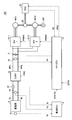
- FIG. 1 is a schematic configuration diagram of a vehicle according to an embodiment of the present invention. It is a block diagram showing a control structure in HV-ECU according to the embodiment of the present invention. It is a figure which shows an example of the charging / discharging allowable power characteristic of an electrical storage part. It is a figure which shows the time change of charge / discharge allowable power for control. It is a figure which shows an example of the electric power restriction violation which generate
- FIG. 1 is a schematic configuration diagram of a vehicle 100 according to an embodiment of the present invention.
- a vehicle 100 according to the embodiment of the present invention is typically a hybrid vehicle, and is equipped with an internal combustion engine (engine) and an electric motor (motor generator), and the driving force from each is optimal. Drive with the ratio controlled.
- engine internal combustion engine
- motor generator electric motor
- vehicle 100 includes an engine (ENG) 20, a first motor generator MG 1, and a second motor generator MG 2 as driving force sources, which are mechanically connected via power split mechanism 22.
- the power split mechanism 22 includes a planetary gear mechanism including three elements of a planetary carrier, a sun gear, and a ring gear, and the engine 20, the first motor generator MG1, and the second motor generator MG2 are connected to each element. Then, according to the traveling state of the vehicle 100, the driving force is distributed and combined among the three persons via the power split mechanism 22, and as a result, the driving wheels 24F are driven.
- power split mechanism 22 splits the driving force generated by the operation of engine 20 into two parts, distributes one of them to first motor generator MG1 side, and the remaining part to second motor generator MG2 side. To distribute.
- the driving force distributed from the power split mechanism 22 to the first motor generator MG1 side is used for power generation, while the driving force distributed to the second motor generator MG2 side is the driving force generated by the second motor generator MG2. It is synthesized and used to drive the drive wheel 24F.
- first inverter (INV1) 10-1 and the second inverter (INV2) 10-2 respectively associated with the motor generators MG1 and MG2 mutually convert DC power and AC power.
- first inverter 10-1 converts AC power generated in first motor generator MG1 into DC power in accordance with switching command PWM1 from HV-ECU 2, and supplies the DC power to positive bus MPL and negative bus MNL.
- the second inverter 10-2 converts the DC power supplied via the positive bus MPL and the negative bus MNL into AC power in response to the switching command PWM2 from the HV-ECU 2, and generates the second motor generator MG2.
- vehicle 100 is a power generation unit that includes second motor generator MG2 that can generate electric power by receiving electric power from power storage unit 6 as a load device, and that can generate electric power by receiving driving force from engine 20.
- First motor generator MG1 is provided.
- the power storage unit 6 is a chargeable / dischargeable power storage element, and typically includes a secondary battery such as a lithium ion battery or a nickel metal hydride battery, or a power storage element such as an electric double layer capacitor.
- a converter (CONV) 8 capable of mutually converting DC voltages is disposed, and the input / output voltage of the power storage unit 6, the positive bus MPL, and the negative The line voltage to the bus line MNL is boosted or lowered mutually.
- the step-up / step-down operation in converter 8 is controlled in accordance with switching command PWC from HV-ECU 2.
- FIG. 1 illustrates a vehicle on which only one power storage unit 6 is mounted
- the number of power storage units 6 is not limited to one.
- a configuration in which a plurality of power storage units are mounted may be employed in accordance with traveling performance required for the vehicle 100 and the like. At this time, a configuration in which the same number of converters 8 are mounted corresponding to each power storage unit is desirable.
- the current detection unit 12 inserted in the positive line PL detects the current value Ib exchanged between the power storage unit 6 and the converter 8, and is connected between the positive line PL and the negative line NL.
- the voltage detection unit 14 detects a voltage value Vb related to charging or discharging of the power storage unit 6.
- a temperature detection unit 16 is disposed in the vicinity of the battery cells constituting the power storage unit 6 and detects the temperature Tb of the power storage unit 6. Note that the temperature detection unit 16 may be configured to output a representative value obtained from detection values obtained by a plurality of temperature detection elements arranged in association with a plurality of battery cells constituting the power storage unit 6.
- Each part constituting the vehicle 100 is realized by cooperative control of the HV-ECU 2 and the battery ECU 4.
- the HV-ECU 2 and the battery ECU 4 are connected to each other via a communication line so that various information and signals can be exchanged.
- the battery ECU 4 is a control device that mainly manages charge state management and abnormality detection of the power storage unit 6, and as an example, a CPU (Central Processing Unit), ROM (Read Only Memory), RAM (Random Access Memory), etc.
- a microcomputer including a storage unit is mainly used. Specifically, the battery ECU 4 determines the power storage unit based on the temperature Tb detected by the temperature detection unit 16, the voltage value Vb detected by the voltage detection unit 14, and the current value Ib detected by the current detection unit 12. 6 is calculated (SOC: State Of Charge; hereinafter referred to as “SOC”).
- the state of charge value indicates the amount of charge (remaining charge amount) when the power storage unit 6 is fully charged, and as an example, the ratio of the current charge amount to the full charge capacity (0 to 100%).
- Battery ECU 4 transmits the calculated SOC of power storage unit 6 to HV-ECU 2 together with temperature Tb detected by temperature detection unit 16.
- HV-ECU 2 controls engine 20, converter 8, inverters 10-1, 10-2 and motor generators MG 1, MG 2 in order to generate vehicle driving force according to the driver's request when vehicle 100 is traveling.
- the control device is configured mainly by a microcomputer including a CPU and a storage unit such as a ROM or a RAM.
- the HV-ECU 2 controls the electric power charged / discharged by the power storage unit 6.
- vehicle 100 is a hybrid vehicle, and HV-ECU 2 performs control by sequentially switching between an EV (Electric Vehicle) traveling mode and an HV (Hybrid Vehicle) traveling mode. That is, when an ignition-on command IGON is given by the driver's operation, HV-ECU 2 switches between EV traveling mode and HV traveling mode so that the SOC of power storage unit 6 is maintained within a predetermined range.
- EV Electric Vehicle
- HV Hybrid Vehicle
- control is performed so that the vehicle travels mainly only with the driving force from the second motor generator MG2, so that the first motor generator MG1 that receives the power of the engine 20 is not operated, and the first motor generator is not operated.
- Charging of power storage unit 6 by MG1 is limited. Therefore, even if power storage unit 6 may be charged by the regenerative operation of second motor generator MG2, the SOC of power storage unit 6 inevitably decreases. As a result, when the SOC of power storage unit 6 falls below a predetermined value, HV-ECU 2 shifts to an HV traveling mode in which charging of power storage unit 6 by first motor generator MG1 is allowed.
- the HV-ECU 2 is given a request unrelated to the driving force request such as catalyst warm-up or air conditioning request when a driving force request such as rapid acceleration is given from the driver.
- the engine 20 is started to shift to the HV traveling mode.
- the HV-ECU 2 determines the engine 20 based on the signals from the sensors, the traveling state, the accelerator opening (none of which are shown), etc., so that the overall fuel consumption efficiency is optimized.
- Target values for the rotational speed, the amount of power generated by first motor generator MG1, and the torque of second motor generator MG2 are determined.
- the SOC of the power storage unit 6 is also considered, and the power charged / discharged by the power storage unit 6 is managed so that the SOC of the power storage unit 6 is maintained within a predetermined range. That is, the difference between the generated power generated by first motor generator MG1 in response to a part of the power from engine 20 and the power consumption used by second motor generator MG2 for generating the driving force is the charge in power storage unit 6. Since it corresponds to the discharge power, the amount of power generated by the first motor generator MG1 and the power consumed by the second motor generator MG2 are determined according to the SOC of the power storage unit 6.
- FIG. 2 is a block diagram showing a control structure in HV-ECU 2 according to the embodiment of the present invention.
- control structure in HV-ECU 2 includes charge / discharge allowable power calculation unit 200, charge / discharge allowable power control unit 202, output management unit 204, distribution unit 206, converter control unit 208, Inverter control unit 210.
- Charging / discharging allowable power calculation unit 200 when receiving the SOC and temperature Tb of power storage unit 6 from battery ECU 4, calculates the power (charge allowable power Win and discharge allowable power Wout) that is allowed to be charged and discharged by power storage unit 6. .
- charge / discharge allowable power calculation unit 200 stores charge / discharge allowable power characteristics that define charge allowable power Win and discharge allowable power Wout in association with the SOC and temperature Tb of power storage unit 6 in a map format.
- FIG. 3 is a diagram illustrating an example of charge / discharge allowable power characteristics.
- Charging / discharging allowable power calculation unit 200 refers to a map (FIG. 3) stored based on the SOC and temperature Tb of power storage unit 6 at each time point, and charges / discharges corresponding charging allowable power Win and discharging allowable power Wout. This is sent to the allowable power control unit 202.
- the charge / discharge allowable power control unit 202 sets the control charge allowable power Win # according to the charge allowable power Win. Further, charge / discharge allowable power control unit 202 sets control discharge allowable power Wout # in accordance with discharge allowable power Wout.
- the charge / discharge allowable powers Win # and Wout # are stored in the power storage unit 204 when the output management unit 204 determines the power generation amount of the first motor generator MG1 and the target value of power consumption in the second motor generator MG2. 6 is used as charge / discharge allowable power.
- charge / discharge allowable powers Win # and Wout # for control charge / discharge allowable powers Win and Wout calculated based on SOC and temperature Tb of power storage unit 6 at each time point are used. A correction is made to limit the rate of change.
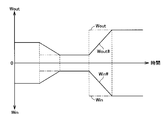
- FIG. 4 is a diagram showing temporal changes in the control charge / discharge allowable powers Win # and Wout #. Note that solid lines in the figure indicate control charge / discharge allowable powers Win # and Wout #, and alternate long and short dash lines in the figure indicate charge / discharge allowable powers Win and Wout at each time point.
- charge / discharge allowable powers Win and Wout at each time point change (increase or decrease) every moment according to the SOC and temperature Tb of power storage unit 6. For example, when the temperature Tb of the power storage unit 6 exceeds a predetermined threshold, both the charge allowable power Win and the discharge allowable power Wout decrease in order to reduce the charge / discharge current and suppress the temperature increase of the power storage unit 6. . Further, when the temperature Tb of the power storage unit 6 is low, the charge / discharge characteristics are deteriorated as compared with the normal temperature. Therefore, in order to avoid overcharge and overdischarge, the allowable charge power Win and the allowable discharge power Wout are Both decrease.
- the motor generators MG1 and MG2 are controlled according to the reduced charge / discharge allowable powers Win and Wout, the power charged / discharged by the power storage unit 6 is limited within the range of the charge / discharge allowable powers Win and Wout. Therefore, the temperature rise, overcharge, overdischarge, etc. of the power storage unit 6 can be suppressed.
- the vehicle driving force generated from the engine 20 and the second motor generator MG2 is abruptly reduced, which may cause the driver to feel uncomfortable. Moreover, since fluctuations in vehicle driving force are induced, drivability may be deteriorated.
- the charge / discharge allowable power control unit 202 As shown in FIG. 4, the charge / discharge allowable power Win, When Wout changes, correction for limiting the change rate to a predetermined change rate V1 is performed, and control charge / discharge allowable powers Win # and Wout # are set.
- the predetermined change speed V1 is such that the power charged / discharged by the power storage unit 6 is fed back in accordance with target values for the rotational speed of the engine 20, the power generation amount of the first motor generator MG1, and the torque of the second motor generator MG2. In consideration of being controlled, it is set so as not to exceed the change rate of the power charged / discharged by the power storage unit 6 in the feedback control. According to this, since it is possible to suppress the vehicle driving force from fluctuating due to sudden changes in the charge / discharge allowable powers Win and Wout, it is possible to prevent the drivability from being deteriorated.
- output management unit 204 falls within the range of control charging / discharging allowable powers Win #, Wout #.
- the power target value corresponding to the driver request and the driving situation is determined and provided to the distribution unit 206.
- the driver request includes an accelerator pedal depression amount, a brake pedal depression amount, a shift lever position (none of which is shown), and the like.
- the traveling state includes information indicating that the vehicle 100 is accelerating or decelerating.
- the output management unit 204 determines an output command Nref for the engine 20 together with the power target value in order to generate a vehicle driving force according to the driver's request.
- Distribution unit 206 distributes the power target value determined by output management unit 204 based on engine speed NE, and generates MG1 power generation target value for first motor generator MG1 and MG2 torque target for second motor generator MG2. Calculate the value. Distribution unit 206 then outputs a control command corresponding to the calculated MG1 power generation target value and MG2 torque target value to inverter control unit 210, and at the same time, a control command corresponding to power supply and demand in vehicle 100 to converter control unit 208. Output.
- Inverter control unit 210 generates switching commands PWM1 and PWM2 for driving motor generators MG1 and MG2 in accordance with a control command from distribution unit 206.
- the switching commands PWM1 and PWM2 are output to inverters 10-1 and 10-2, respectively.
- Converter control unit 208 generates switching command PWC in accordance with a control command from distribution unit 206 such that predetermined discharge power is supplied from power storage unit 6 to second motor generator MG2. This switching command PWC is output to converter 8. Converter 8 performs a voltage conversion operation according to switching command PWC, so that the discharge power of power storage unit 6 is controlled.
- HV-ECU 2 corrects charge / discharge allowable power Win, Wout in accordance with the SOC of power storage unit 6 and temperature Tb in a direction in which the rate of change is limited. Control charge / discharge allowable powers Win # and Wout # are set. Then, HV-ECU 2 controls the power generation amount of first motor generator MG1 and the power consumption of second motor generator MG2 so as to be within the range of the set charge / discharge allowable powers Win #, Wout #. By adopting such a control configuration, it is possible to avoid overdischarge and overcharge of the power storage unit 6 by maintaining the SOC of the power storage unit 6 within a predetermined range while ensuring drivability.
- the power storage unit 6 performs the start control of the engine 20.
- a so-called power restriction violation may occur in which the electric power to be charged / discharged exceeds the original charge / discharge allowable power of the power storage unit 6 limited by the SOC of the power storage unit 6 and the temperature Tb.
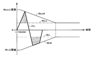
- FIG. 5 is a diagram illustrating an example of a power restriction violation that occurs in the power storage unit 6.
- an ignition on command IGON is given by a driver's operation at time t1.
- charging / discharging allowable power Win #, Wout # of power storage unit 6 is set to the maximum value among the charging / discharging allowable power characteristics shown in FIG.
- the maximum value of charge allowable power among the charge / discharge allowable power characteristics is expressed as a Win upper limit value
- the maximum value of discharge allowable power is expressed as a Wout upper limit value.
- the restriction on the power charged / discharged in the power storage unit 6 at time t1 is normally canceled because the HV-ECU 2 normally detects various sensors within a certain period from the timing when the ignition-on command IGON is given. Is determined, and when the various sensors are determined to be normal, the SOC of the power storage unit 6 and the temperature Tb are detected based on the sensor output, so that the ignition-on command IGON is This is because accurate charge / discharge allowable powers Win and Wout cannot be calculated at a given time t1.
- the charge / discharge allowable powers Win #, Wout # for control at time t1 are uniformly fixed to the maximum values (Win upper limit value and Wout upper limit value) of the charge / discharge allowable power characteristics of the power storage unit 6, thereby In spite of the fact that sufficient electric power is stored for EV driving, it is possible to prevent problems such as erroneously determining that the battery is in a low charge state and starting the engine 20. Yes.
- control charging / discharging allowable powers Win # and Wout # so as to decrease at the predetermined change speed V1 using the Win upper limit value and the Wout upper limit value as initial values.
- control charging / discharging allowable powers Win #, Wout # decrease at a predetermined change rate V1 until reaching charging / discharging allowable powers Win, Wout calculated based on the SOC of power storage unit 6 and temperature Tb.
- a catalytic converter for purifying exhaust gas from the engine 20 is mounted in the same manner as a vehicle using only a conventional engine as a driving force source. Therefore, when the system of the vehicle 100 is started in a low temperature environment, a warm-up request for promoting warm-up of the engine 20 or the catalytic converter may be given.
- HV-ECU 2 causes torque of first motor generator MG1 and second motor generator to fall within the range of control charge / discharge allowable powers Win #, Wout #.
- a target value for the power generation amount of MG2 is determined, and the power charged / discharged in power storage unit 6 is feedback-controlled according to the determined target value.
- first motor generator MG1 is used as a starter that starts the engine 20. Therefore, HV-ECU 2 calculates a torque target value for driving first motor generator MG1 so that the rotational speed of engine 20 is set to the idle rotational speed within the range of control discharge allowable power Wout #. .
- first motor generator MG1 is supplied with electric power from power storage unit 6 and is driven as an electric motor, and cranks and starts engine 20 via power split mechanism 22.
- HV-ECU 2 changes the torque of second motor generator MG2 so as to prevent the occurrence of rattling noise when such rattling noise may occur.
- the HV-ECU 2 when the driving torque of the vehicle 100 is within a preset rattling sound generation torque region, the HV-ECU 2 is configured so that the driving torque deviates from the rattling sound generation torque region.
- the torque of second motor generator MG2 is changed.
- the HV-ECU 2 controls the second motor generator MG2 to be in the regenerative mode in order to reduce the rattling noise by operating in the direction in which the gear backlash is reduced.
- the HV-ECU 2 calculates the MG2 power generation target value for the second motor generator MG2 within the range of the control charging allowable power Win #. Then, HV-ECU 2 performs feedback control of the electric power charged in power storage unit 6 according to the calculated target value. As a result, rattling noise is prevented from being generated in the power split mechanism 22 due to torque fluctuations of the engine 20.
- the power charged / discharged by the power storage unit 6 (corresponding to Pm in FIG. 5) is controlled according to the control charge / discharge allowable powers Win #, Wout #.
- the charge / discharge allowable powers Win and Wout of the power storage unit 6 are significantly limited according to the charge / discharge allowable power characteristics of FIG. .
- FIG. 1 In FIG.
- control charging / discharging allowable powers Win #, Wout # (corresponding to a solid line) and charging / discharging allowable powers Win, Wout (corresponding to an alternate long and short dash line) according to the SOC and temperature Tb of power storage unit 6 are shown.
- the power storage unit 6 is in a low temperature and low charge state, it is clear that the difference between the two becomes large. Therefore, when the above-described start control of engine 20 is performed within the range of charge / discharge allowable powers Win #, Wout # for control, power storage unit 6 is charged / discharged with power exceeding the original charge / discharge allowable powers Win, Wout. As a result, a power limit violation occurs in the area indicated by hatching in FIG. Thereby, there exists a possibility that the overcharge and overdischarge of the electrical storage part 6 may generate
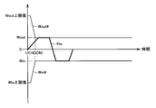
- FIG. 6 shows temporal changes in control charge / discharge allowable powers Win # and Wout # according to the embodiment of the present invention.
- solid lines indicate control charge / discharge allowable powers Win # and Wout #
- alternate long and short dash lines in the figure indicate charge / discharge allowable powers Win and Wout at each time point.
- the charging / discharging allowable powers Win # and Wout # for control at time t1 are uniformly fixed to the maximum value of the charging / discharging allowable power characteristics of power storage unit 6, so that the power sufficient for EV running in power storage unit 6 is achieved. In spite of being stored, it is possible to prevent the occurrence of problems such as the erroneous determination of the low charge state and the start of the engine 20.
- the HV-ECU 2 sets the control charge / discharge allowable powers Win # and Wout # so as to decrease using the Win upper limit value and the Wout upper limit value as initial values.
- the HV-ECU 2 controls the charging / discharging allowable power for control so that the charging / discharging allowable power Win #, Wout # decreases at a predetermined change speed V2 (> V1) exceeding the predetermined change speed V1 described above. Win # and Wout # are set.
- the predetermined change speed V2 is set to a value higher than the change speed of the power charged / discharged by the power storage unit 6 in the feedback control according to the power target value according to the driver request.
- the restriction on the change speed of the control charge / discharge allowable powers Win # and Wout # when the system of the vehicle 100 is started is released when the system is started as compared to when the vehicle 100 is running.
- the system of the vehicle 100 since the vehicle driving force does not fluctuate rapidly, it is less effective to limit the rate of change of the control charging / discharging allowable powers Win # and Wout #. . Therefore, in such a case, it is possible to effectively prevent the occurrence of a power restriction violation for the power storage unit 6 due to the start control of the engine 20 by releasing the restriction on the change speed.
- the power storage unit 6 corresponds to a “power storage unit”
- the engine 20 corresponds to an “internal combustion engine”
- the first motor generator MG1 corresponds to the “driving force generation unit”
- the battery ECU 4 and the HV-ECU 2 correspond to the “control device”.
- the battery ECU 4 implements a “power storage unit state detection unit”
- the HV-ECU 2 implements a “charge / discharge allowable power calculation unit”, a “charge / discharge allowable power control unit”, and a “charge / discharge control unit”.
- FIG. 7 is a flowchart relating to setting processing of control charge / discharge allowable powers Win # and Wout # according to the embodiment of the present invention.
- the flowchart shown in FIG. 7 can be realized by executing a program stored in advance in HV-ECU 2 and battery ECU 4.
- HV-ECU 2 determines whether or not vehicle 100 is at the time of system activation. Specifically, the HV-ECU 2 determines whether or not an ignition on command IGON has been given by the driver's operation (step S01). When ignition on command IGON is not given (NO in step S01), that is, when vehicle 100 is not at the time of system activation, HV-ECU 2 determines the SOC and temperature of power storage unit 6 at each time given from battery ECU 4 With reference to the map (FIG. 3) stored based on Tb, charge / discharge allowable powers Win and Wout of power storage unit 6 are calculated (step S02).
- the HV-ECU 2 performs correction for limiting the change rate to a predetermined change rate V1 set in advance for the charge / discharge allowable powers Win and Wout of the power storage unit 6 calculated in step S02.
- Control charge / discharge allowable powers Win # and Wout # are set (step S03).
- step S01 when the ignition on command IGON is given in step S01 (YES in step S01), that is, when vehicle 100 is in the system start-up, HV-ECU 2 With reference to a map (FIG. 3) stored based on the SOC and temperature Tb of power storage unit 6 at the time, charge / discharge allowable powers Win and Wout of power storage unit 6 are calculated (step S04). Then, the HV-ECU 2 uses the Win upper limit value and the Wout upper limit value as initial values, and decreases toward a charge / discharge allowable power Win, Wout calculated in step S04 at a predetermined change speed V2 that exceeds the predetermined change speed V1. The control charge / discharge allowable powers Win # and Wout # are set to (step S05).
- HV-ECU 2 determines a power target value corresponding to the driver request and the driving situation within the range of control charge / discharge allowable power Win #, Wout # set in steps S03 and S05 (step S06).
- the determined power target value is distributed to calculate the MG1 power generation target value for the first motor generator MG1 and the MG2 torque target value for the second motor generator MG2.
- HV-ECU 2 outputs a control command corresponding to the calculated MG1 power generation target value and MG2 torque target value to inverter control unit 210, and at the same time, sends a control command corresponding to power supply / demand in vehicle 100 to converter control unit 208.
- Output step S07).
- the charge / discharge allowable power calculated based on the state of the power storage unit is corrected for the rate of change and the charge / discharge allowable power for control is set.
- the change speed is variably set according to the state of the vehicle.
- the present invention can be used for a hybrid vehicle equipped with a chargeable / dischargeable power storage unit.
Abstract
Description
図1を参照して、この発明の実施の形態に従う車両100は、代表的にハイブリッド車両であり、内燃機関(エンジン)と電動機(モータジェネレータ)とを搭載し、それぞれからの駆動力を最適な比率に制御して走行する。 FIG. 1 is a schematic configuration diagram of a
Referring to FIG. 1, a
以下、上述した蓄電部6のSOCに応じてHV走行モードにおける蓄電部6の充放電管理を行なうための制御構造について説明する。 (Charge / discharge management of power storage unit)
Hereinafter, a control structure for performing charge / discharge management of
図5を参照して、時刻t1において、運転者の操作によってイグニッションオン指令IGONが与えられたものとする。この時刻t1においては、蓄電部6の制御用充放電許容電力Win♯,Wout♯は、図3に示す充放電許容電力特性のうちの最大値に設定される。なお、図5では、充放電許容電力特性のうちの充電許容電力の最大値がWin上限値と表記され、放電許容電力の最大値がWout上限値と表記されている。 FIG. 5 is a diagram illustrating an example of a power restriction violation that occurs in the
Referring to FIG. 5, it is assumed that an ignition on command IGON is given by a driver's operation at time t1. At time t1, charging / discharging allowable power Win #, Wout # of
図7は、この発明の実施の形態に従う制御用充放電許容電力Win♯,Wout♯の設定処理に係るフローチャートである。なお、図7に示すフローチャートは、HV-ECU2および電池ECU4において予め格納したプログラムを実行することで実現できる。 The above processing can be summarized in a processing flow as shown in FIG.
FIG. 7 is a flowchart relating to setting processing of control charge / discharge allowable powers Win # and Wout # according to the embodiment of the present invention. The flowchart shown in FIG. 7 can be realized by executing a program stored in advance in HV-
Claims (4)
- 内燃機関(20)と、
前記内燃機関(20)の作動により生じる動力を受けて発電可能な発電部(MG1)と、
前記発電部(MG1)からの電力を受けて充電可能に構成された蓄電部(6)と、
前記蓄電部(6)から電力の供給を受けて車両(100)の駆動力を発生する駆動力発生部(MG2)と、
運転者要求に応じて発生させる車両駆動力を制御するとともに、前記蓄電部(6)で充放電される電力を制御する制御装置(2,4)とを備え、
前記制御装置(2,4)は、
前記蓄電部(6)の充電状態値および温度を検出する蓄電部状態検出部と、
前記蓄電部状態検出部によって検出された前記蓄電部(6)の充電状態値および温度に基づいて、前記蓄電部(6)において許容される充放電電力を算出する充放電許容電力演算部と、
前記充放電許容電力演算部によって算出された充放電許容電力に対して、所定の第1の変化速度で変化するように制限が課されるように補正を施して、制御用充放電許容電力を設定する充放電許容電力制御部と、
前記充放電許容電力制御部によって設定された前記制御用充放電許容電力の範囲内で、運転者要求に応じた電力目標値を決定するとともに、該電力目標値に従って前記蓄電部(6)で充放電される電力をフィードバック制御する充放電制御部とを含み、
前記充放電許容電力制御部は、前記車両(100)の起動時においては、前記蓄電部(6)において許容される充放電電力の最大値を初期値とし、かつ、該初期値から前記第1の変化速度を上回る所定の第2の変化速度で減少するように、前記制御用充放電許容電力を設定する、ハイブリッド車両。 An internal combustion engine (20);
A power generation unit (MG1) capable of receiving power generated by the operation of the internal combustion engine (20) and generating power;
A power storage unit (6) configured to be able to be charged by receiving power from the power generation unit (MG1);
A driving force generator (MG2) that receives the supply of electric power from the power storage unit (6) to generate the driving force of the vehicle (100);
A control device (2, 4) for controlling the vehicle driving force to be generated in response to a driver request and for controlling the electric power charged / discharged by the power storage unit (6),
The control device (2, 4)
A power storage unit state detection unit for detecting a charge state value and temperature of the power storage unit (6);
A charge / discharge allowable power calculation unit that calculates charge / discharge power allowed in the power storage unit (6) based on a charge state value and temperature of the power storage unit (6) detected by the power storage unit state detection unit;
The charge / discharge allowable power calculated by the charge / discharge allowable power calculation unit is corrected so as to be restricted so as to change at a predetermined first change rate, and the charge / discharge allowable power for control is calculated. Charge / discharge allowable power control unit to be set;
Within the range of the charge / discharge allowable power for control set by the charge / discharge allowable power control unit, a power target value corresponding to the driver's request is determined and charged by the power storage unit (6) according to the power target value. A charge / discharge control unit that feedback-controls the discharged power,
The charge / discharge allowable power control unit sets, as an initial value, a maximum value of charge / discharge power allowed in the power storage unit (6) when the vehicle (100) is started, and the first value is determined based on the initial value. A hybrid vehicle in which the control charge / discharge allowable power is set so as to decrease at a predetermined second change rate exceeding the change rate. - 前記第1の変化速度は、前記電力目標値に従って前記蓄電部(6)で充放電される電力の変化速度を超えないように設定され、
前記第2の変化速度は、前記電力目標値に従って前記蓄電部(6)で充放電される電力の変化速度よりも高くなるように設定される、請求の範囲第1項に記載のハイブリッド車両。 The first change rate is set so as not to exceed a change rate of power charged / discharged in the power storage unit (6) according to the power target value.
2. The hybrid vehicle according to claim 1, wherein the second change speed is set to be higher than a change speed of electric power charged / discharged in the power storage unit (6) according to the electric power target value. - ハイブリッド車両(100)の制御方法であって、
前記ハイブリッド車両(100)は、
内燃機関(20)と、
前記内燃機関(20)の作動により生じる動力を受けて発電可能な発電部(MG1)と、
前記発電部(MG1)からの電力を受けて充電可能に構成された蓄電部(6)と、
前記蓄電部(6)から電力の供給を受けて車両駆動力を発生する駆動力発生部(MG2)とを含み、
前記制御方法は、
前記蓄電部(6)の充電状態値および温度を検出するステップと、
前記検出するステップによって検出された前記蓄電部(6)の充電状態値および温度に基づいて、前記蓄電部(6)において許容される充放電電力を算出するステップと、
前記算出するステップによって算出された充放電許容電力に対して、所定の第1の変化速度で変化するように制限が課されるように補正を施して、制御用充放電許容電力を設定するステップと、
前記設定するステップによって設定された前記制御用充放電許容電力の範囲内で、運転者要求に応じた電力目標値を決定するとともに、該電力目標値に従って前記蓄電部(6)で充放電される電力をフィードバック制御するステップとを備え、
前記設定するステップは、前記ハイブリッド車両(100)の起動時においては、前記蓄電部(6)において許容される充放電電力の最大値を初期値とし、かつ、該初期値から前記第1の変化速度を上回る所定の第2の変化速度で減少するように、前記制御用充放電許容電力を設定する、ハイブリッド車両の制御方法。 A control method for a hybrid vehicle (100), comprising:
The hybrid vehicle (100)
An internal combustion engine (20);
A power generation unit (MG1) capable of receiving power generated by the operation of the internal combustion engine (20) and generating power;
A power storage unit (6) configured to be able to be charged by receiving power from the power generation unit (MG1);
A driving force generator (MG2) that receives a supply of electric power from the power storage unit (6) and generates a vehicle driving force,
The control method is:
Detecting a charge state value and temperature of the power storage unit (6);
Calculating charge / discharge power allowed in the power storage unit (6) based on the charge state value and temperature of the power storage unit (6) detected by the detecting step;
A step of correcting the charge / discharge allowable power calculated in the calculating step so as to be limited so as to change at a predetermined first change rate, and setting the control charge / discharge allowable power. When,
Within the range of the control charging / discharging allowable power set by the setting step, a power target value corresponding to a driver request is determined, and charging / discharging is performed by the power storage unit (6) according to the power target value. And feedback control of the power,
In the setting step, when the hybrid vehicle (100) is started, a maximum value of charge / discharge power allowed in the power storage unit (6) is set as an initial value, and the first change from the initial value is performed. A control method for a hybrid vehicle, wherein the control charge / discharge allowable power is set so as to decrease at a predetermined second change rate exceeding the speed. - 前記第1の変化速度は、前記電力目標値に従って前記蓄電部(6)で充放電される電力の変化速度を超えないように設定され、
前記第2の変化速度は、前記電力目標値に従って前記蓄電部(6)で充放電される電力の変化速度よりも高くなるように設定される、請求の範囲第3項に記載のハイブリッド車両の制御方法。 The first change rate is set so as not to exceed a change rate of power charged / discharged in the power storage unit (6) according to the power target value.
4. The hybrid vehicle according to claim 3, wherein the second change speed is set to be higher than a change speed of electric power charged and discharged by the power storage unit (6) according to the power target value. Control method.
Priority Applications (5)
| Application Number | Priority Date | Filing Date | Title |
|---|---|---|---|
| US13/127,575 US8880251B2 (en) | 2008-11-05 | 2008-11-05 | Hybrid vehicle and method of controlling hybrid vehicle |
| JP2010536603A JP4978735B2 (en) | 2008-11-05 | 2008-11-05 | Hybrid vehicle and control method of hybrid vehicle |
| CN200880131876.2A CN102202947B (en) | 2008-11-05 | 2008-11-05 | Hybrid vehicle and hybrid vehicle control method |
| EP08877961.6A EP2363329B1 (en) | 2008-11-05 | 2008-11-05 | Hybrid vehicle and hybrid vehicle control method |
| PCT/JP2008/070092 WO2010052766A1 (en) | 2008-11-05 | 2008-11-05 | Hybrid vehicle and hybrid vehicle control method |
Applications Claiming Priority (1)
| Application Number | Priority Date | Filing Date | Title |
|---|---|---|---|
| PCT/JP2008/070092 WO2010052766A1 (en) | 2008-11-05 | 2008-11-05 | Hybrid vehicle and hybrid vehicle control method |
Publications (1)
| Publication Number | Publication Date |
|---|---|
| WO2010052766A1 true WO2010052766A1 (en) | 2010-05-14 |
Family
ID=42152582
Family Applications (1)
| Application Number | Title | Priority Date | Filing Date |
|---|---|---|---|
| PCT/JP2008/070092 WO2010052766A1 (en) | 2008-11-05 | 2008-11-05 | Hybrid vehicle and hybrid vehicle control method |
Country Status (5)
| Country | Link |
|---|---|
| US (1) | US8880251B2 (en) |
| EP (1) | EP2363329B1 (en) |
| JP (1) | JP4978735B2 (en) |
| CN (1) | CN102202947B (en) |
| WO (1) | WO2010052766A1 (en) |
Cited By (7)
| Publication number | Priority date | Publication date | Assignee | Title |
|---|---|---|---|---|
| JP2013126825A (en) * | 2011-12-19 | 2013-06-27 | Toyota Motor Corp | Control device for vehicle |
| WO2013145099A1 (en) * | 2012-03-26 | 2013-10-03 | トヨタ自動車株式会社 | Hybrid vehicle drive control device |
| JP2016127770A (en) * | 2015-01-08 | 2016-07-11 | トヨタ自動車株式会社 | Power supply device |
| JP2016208729A (en) * | 2015-04-24 | 2016-12-08 | トヨタ自動車株式会社 | Control device of vehicle and control method of vehicle |
| WO2021085441A1 (en) * | 2019-10-29 | 2021-05-06 | 株式会社デンソー | Control device |
| WO2023007872A1 (en) * | 2021-07-27 | 2023-02-02 | ビークルエナジージャパン株式会社 | Battery control method |
| DE112012006106B4 (en) | 2012-03-26 | 2023-07-27 | Toyota Jidosha Kabushiki Kaisha | vehicle control device |
Families Citing this family (20)
| Publication number | Priority date | Publication date | Assignee | Title |
|---|---|---|---|---|
| JP2008120186A (en) * | 2006-11-10 | 2008-05-29 | Toyota Motor Corp | Hybrid vehicle, and motor cruisable area displaying method |
| CN102666235B (en) * | 2009-11-30 | 2015-08-05 | 丰田自动车株式会社 | The control setup of motor vehicle driven by mixed power |
| JP5556586B2 (en) * | 2010-10-26 | 2014-07-23 | トヨタ自動車株式会社 | Hybrid car |
| JPWO2013027337A1 (en) * | 2011-08-24 | 2015-03-05 | パナソニック株式会社 | Vehicle power supply |
| JP5247899B1 (en) * | 2012-02-15 | 2013-07-24 | 株式会社小松製作所 | Capacitor charge / discharge control device, capacitor charge / discharge control method, and hybrid work machine equipped with capacitor charge / discharge control device |
| US9090243B2 (en) * | 2012-06-15 | 2015-07-28 | Fca Us Llc | Hybrid vehicle control |
| JP6107349B2 (en) * | 2013-04-11 | 2017-04-05 | スズキ株式会社 | Battery charge / discharge control device |
| FR3013151B1 (en) * | 2013-11-13 | 2017-12-22 | Renault Sas | METHOD FOR MANAGING THE AVAILABLE POWER OF A BATTERY |
| DE102014203417A1 (en) * | 2014-02-26 | 2015-08-27 | Robert Bosch Gmbh | Method for monitoring a state of charge |
| CN104494595B (en) * | 2014-12-11 | 2018-09-18 | 中联重科股份有限公司 | The Poewr control method and device of hybrid vehicle, dynamical system |
| JP6390514B2 (en) * | 2015-05-22 | 2018-09-19 | 株式会社デンソー | Power control system |
| JP6354685B2 (en) * | 2015-07-10 | 2018-07-11 | トヨタ自動車株式会社 | Battery control device |
| JP6954051B2 (en) * | 2017-11-27 | 2021-10-27 | トヨタ自動車株式会社 | Hybrid car |
| JP7115082B2 (en) * | 2018-07-09 | 2022-08-09 | 株式会社デンソー | Charging control device and charging control system |
| JP7276110B2 (en) * | 2019-12-18 | 2023-05-18 | トヨタ自動車株式会社 | power train system |
| JP7272258B2 (en) | 2019-12-19 | 2023-05-12 | トヨタ自動車株式会社 | vehicle |
| JP7226296B2 (en) | 2019-12-19 | 2023-02-21 | トヨタ自動車株式会社 | vehicle, vehicle control system |
| JP7276115B2 (en) | 2019-12-19 | 2023-05-18 | トヨタ自動車株式会社 | Hybrid vehicle, travel control system, and hybrid vehicle control method |
| KR102654165B1 (en) * | 2020-07-28 | 2024-04-02 | 세메스 주식회사 | Apparatus for managing power of article transport vehicle in article transport system |
| CN114194070A (en) * | 2021-12-28 | 2022-03-18 | 三一汽车起重机械有限公司 | Energy management method and device of power system and engineering machinery |
Citations (5)
| Publication number | Priority date | Publication date | Assignee | Title |
|---|---|---|---|---|
| JP2005124353A (en) * | 2003-10-20 | 2005-05-12 | Toyota Motor Corp | Controller for power storage mechanism |
| JP2006101674A (en) | 2004-09-30 | 2006-04-13 | Toyota Motor Corp | Charging/discharging controller of secondary battery |
| JP2006262634A (en) * | 2005-03-17 | 2006-09-28 | Toyota Motor Corp | Accumulation system and method of treating abnormality of accumulation system |
| JP2006257895A (en) * | 2005-03-15 | 2006-09-28 | Toyota Motor Corp | Power output device, automobile mounted with this device and control method of power output device |
| WO2008111593A1 (en) * | 2007-03-06 | 2008-09-18 | Toyota Jidosha Kabushiki Kaisha | Input/output control device for secondary battery, and vehicle |
Family Cites Families (28)
| Publication number | Priority date | Publication date | Assignee | Title |
|---|---|---|---|---|
| US7469760B2 (en) * | 2000-03-02 | 2008-12-30 | Deka Products Limited Partnership | Hybrid electric vehicles using a stirling engine |
| DE10233821A1 (en) * | 2002-07-25 | 2004-02-05 | Daimlerchrysler Ag | Controlling energy supply of mobile device with electric drive motor(s) and hybrid energy supply system involves deriving difference between fuel cell system and storage battery power components |
| JP3676336B2 (en) * | 2002-10-02 | 2005-07-27 | 本田技研工業株式会社 | Output control device for hybrid vehicle |
| US6936995B2 (en) * | 2003-02-25 | 2005-08-30 | General Motors Corporation | Battery voltage reduction |
| JP3701660B2 (en) * | 2003-07-04 | 2005-10-05 | 本田技研工業株式会社 | Control device for hybrid vehicle |
| US7449891B2 (en) * | 2003-10-14 | 2008-11-11 | General Motors Corporation | Managing service life of a battery |
| US7127337B2 (en) * | 2003-10-14 | 2006-10-24 | General Motors Corporation | Silent operating mode for reducing emissions of a hybrid electric vehicle |
| JP2005143169A (en) * | 2003-11-05 | 2005-06-02 | Yamaha Motor Co Ltd | Electric vehicle |
| US7653474B2 (en) * | 2004-05-14 | 2010-01-26 | Gm Global Technology Operations, Inc. | Method of determining engine output power in a hybrid electric vehicle |
| JP4116609B2 (en) * | 2004-11-04 | 2008-07-09 | パナソニックEvエナジー株式会社 | Power supply control device, electric vehicle and battery control unit |
| CA2523240C (en) * | 2005-10-11 | 2009-12-08 | Delaware Systems Inc. | Universal battery module and controller therefor |
| JP4952031B2 (en) * | 2006-04-14 | 2012-06-13 | トヨタ自動車株式会社 | Power supply device, input / output restriction setting method in power supply device, vehicle and control method thereof |
| JP4784566B2 (en) * | 2006-07-12 | 2011-10-05 | 日産自動車株式会社 | Secondary battery input / output power control apparatus and input / output power control method |
| JP4984754B2 (en) * | 2006-09-04 | 2012-07-25 | トヨタ自動車株式会社 | Power supply system and vehicle equipped with the same |
| JP4236676B2 (en) * | 2006-09-07 | 2009-03-11 | 株式会社日立製作所 | Vehicle drive system |
| JP4743082B2 (en) * | 2006-11-01 | 2011-08-10 | トヨタ自動車株式会社 | Power supply system and vehicle equipped with the same |
| JP4179383B2 (en) * | 2007-02-13 | 2008-11-12 | トヨタ自動車株式会社 | Driving force generation system, vehicle including the same, and control method thereof |
| JP2008207578A (en) * | 2007-02-23 | 2008-09-11 | Toyota Motor Corp | Power output device, its control method, and vehicle |
| US7741805B2 (en) * | 2007-08-14 | 2010-06-22 | Gm Global Technology Operations, Inc. | Method and apparatus for managing power flow of an electric power storage device |
| JP4946749B2 (en) * | 2007-09-14 | 2012-06-06 | 三菱自動車工業株式会社 | Vehicle battery control device |
| US8356472B2 (en) * | 2007-11-05 | 2013-01-22 | Mitsubishi Fuso Truck And Bus Corporation | Exhaust purification device for hybrid electric vehicle |
| US8596390B2 (en) * | 2007-12-05 | 2013-12-03 | Ford Global Technologies, Llc | Torque control for hybrid electric vehicle speed control operation |
| US7957921B2 (en) * | 2008-02-19 | 2011-06-07 | GM Global Technology Operations LLC | Model-based estimation of battery hysteresis |
| CN101244721A (en) * | 2008-03-24 | 2008-08-20 | 南京汽车集团有限公司 | Multi-power-operated control method and system for hybrid power vehicle |
| US8212532B2 (en) * | 2008-07-24 | 2012-07-03 | General Electric Company | Method and system for control of a vehicle energy storage device |
| US8653960B2 (en) * | 2011-01-20 | 2014-02-18 | GM Global Technology Operations LLC | Vehicle gauge for displaying electric mode status and method of doing the same |
| US8937452B2 (en) * | 2011-02-04 | 2015-01-20 | GM Global Technology Operations LLC | Method of controlling a state-of-charge (SOC) of a vehicle battery |
| US9340121B2 (en) * | 2011-04-14 | 2016-05-17 | GM Global Technology Operations LLC | Method and system for heating a vehicle battery |
-
2008
- 2008-11-05 EP EP08877961.6A patent/EP2363329B1/en active Active
- 2008-11-05 CN CN200880131876.2A patent/CN102202947B/en active Active
- 2008-11-05 WO PCT/JP2008/070092 patent/WO2010052766A1/en active Application Filing
- 2008-11-05 JP JP2010536603A patent/JP4978735B2/en active Active
- 2008-11-05 US US13/127,575 patent/US8880251B2/en active Active
Patent Citations (5)
| Publication number | Priority date | Publication date | Assignee | Title |
|---|---|---|---|---|
| JP2005124353A (en) * | 2003-10-20 | 2005-05-12 | Toyota Motor Corp | Controller for power storage mechanism |
| JP2006101674A (en) | 2004-09-30 | 2006-04-13 | Toyota Motor Corp | Charging/discharging controller of secondary battery |
| JP2006257895A (en) * | 2005-03-15 | 2006-09-28 | Toyota Motor Corp | Power output device, automobile mounted with this device and control method of power output device |
| JP2006262634A (en) * | 2005-03-17 | 2006-09-28 | Toyota Motor Corp | Accumulation system and method of treating abnormality of accumulation system |
| WO2008111593A1 (en) * | 2007-03-06 | 2008-09-18 | Toyota Jidosha Kabushiki Kaisha | Input/output control device for secondary battery, and vehicle |
Non-Patent Citations (1)
| Title |
|---|
| See also references of EP2363329A4 |
Cited By (9)
| Publication number | Priority date | Publication date | Assignee | Title |
|---|---|---|---|---|
| JP2013126825A (en) * | 2011-12-19 | 2013-06-27 | Toyota Motor Corp | Control device for vehicle |
| WO2013145099A1 (en) * | 2012-03-26 | 2013-10-03 | トヨタ自動車株式会社 | Hybrid vehicle drive control device |
| DE112012006106B4 (en) | 2012-03-26 | 2023-07-27 | Toyota Jidosha Kabushiki Kaisha | vehicle control device |
| JP2016127770A (en) * | 2015-01-08 | 2016-07-11 | トヨタ自動車株式会社 | Power supply device |
| JP2016208729A (en) * | 2015-04-24 | 2016-12-08 | トヨタ自動車株式会社 | Control device of vehicle and control method of vehicle |
| WO2021085441A1 (en) * | 2019-10-29 | 2021-05-06 | 株式会社デンソー | Control device |
| JP2021072765A (en) * | 2019-10-29 | 2021-05-06 | 株式会社デンソー | Control device |
| JP7359075B2 (en) | 2019-10-29 | 2023-10-11 | 株式会社デンソー | Control device |
| WO2023007872A1 (en) * | 2021-07-27 | 2023-02-02 | ビークルエナジージャパン株式会社 | Battery control method |
Also Published As
| Publication number | Publication date |
|---|---|
| EP2363329A4 (en) | 2016-10-26 |
| CN102202947B (en) | 2014-04-23 |
| CN102202947A (en) | 2011-09-28 |
| JPWO2010052766A1 (en) | 2012-03-29 |
| EP2363329A1 (en) | 2011-09-07 |
| EP2363329B1 (en) | 2018-08-15 |
| US8880251B2 (en) | 2014-11-04 |
| JP4978735B2 (en) | 2012-07-18 |
| US20110213524A1 (en) | 2011-09-01 |
Similar Documents
| Publication | Publication Date | Title |
|---|---|---|
| JP4978735B2 (en) | Hybrid vehicle and control method of hybrid vehicle | |
| JP5429366B2 (en) | Control device for hybrid vehicle and hybrid vehicle including the same | |
| JP4992728B2 (en) | Power supply device and discharge control method thereof | |
| JP5267734B2 (en) | Electric vehicle and control method thereof | |
| JP5716693B2 (en) | Hybrid vehicle | |
| JP5316703B2 (en) | Control device for hybrid vehicle and hybrid vehicle including the same | |
| JP5400697B2 (en) | Control device for hybrid vehicle and hybrid vehicle including the same | |
| US20090131215A1 (en) | Drive force output apparatus, method for controlling same apparatus, and vehicle | |
| WO2013018208A1 (en) | Hybrid vehicle and method for controlling same | |
| WO2012131864A1 (en) | Electric vehicle and control method therefor | |
| JP4595829B2 (en) | Secondary battery control device and control method | |
| WO2011125186A1 (en) | Hybrid-vehicle control device and hybrid vehicle provided therewith | |
| JPWO2012157054A1 (en) | Electric vehicle | |
| JP5848283B2 (en) | Control device for hybrid vehicle and hybrid vehicle including the same | |
| JP5729475B2 (en) | Vehicle and vehicle control method | |
| JP6028328B2 (en) | Hybrid vehicle | |
| JP2010163061A (en) | Power output device, vehicle equipped with the same and method for controlling power output device | |
| JP5682686B2 (en) | Control device for hybrid vehicle | |
| JP2006094628A (en) | Control device of hybrid vehicle | |
| JP2014208504A (en) | Hybrid vehicle controller | |
| JP6930363B2 (en) | Drive device | |
| JP5729461B2 (en) | Control device for hybrid vehicle | |
| JP2016127770A (en) | Power supply device | |
| JP2011225077A (en) | Hybrid automobile |
Legal Events
| Date | Code | Title | Description |
|---|---|---|---|
| WWE | Wipo information: entry into national phase |
Ref document number: 200880131876.2 Country of ref document: CN |
|
| 121 | Ep: the epo has been informed by wipo that ep was designated in this application |
Ref document number: 08877961 Country of ref document: EP Kind code of ref document: A1 |
|
| ENP | Entry into the national phase |
Ref document number: 2010536603 Country of ref document: JP Kind code of ref document: A |
|
| WWE | Wipo information: entry into national phase |
Ref document number: 13127575 Country of ref document: US |
|
| NENP | Non-entry into the national phase |
Ref country code: DE |
|
| WWE | Wipo information: entry into national phase |
Ref document number: 2008877961 Country of ref document: EP |