WO2010047034A1 - Imaging control device for capturing tomogram of eye ground, imaging device, imaging control method, program, and storage medium - Google Patents
Imaging control device for capturing tomogram of eye ground, imaging device, imaging control method, program, and storage medium Download PDFInfo
- Publication number
- WO2010047034A1 WO2010047034A1 PCT/JP2009/004360 JP2009004360W WO2010047034A1 WO 2010047034 A1 WO2010047034 A1 WO 2010047034A1 JP 2009004360 W JP2009004360 W JP 2009004360W WO 2010047034 A1 WO2010047034 A1 WO 2010047034A1
- Authority
- WO
- WIPO (PCT)
- Prior art keywords
- imaging
- fundus
- movement
- photographing
- image
- Prior art date
Links
Images


Classifications
-
- A—HUMAN NECESSITIES
- A61—MEDICAL OR VETERINARY SCIENCE; HYGIENE
- A61B—DIAGNOSIS; SURGERY; IDENTIFICATION
- A61B3/00—Apparatus for testing the eyes; Instruments for examining the eyes
- A61B3/10—Objective types, i.e. instruments for examining the eyes independent of the patients' perceptions or reactions
- A61B3/12—Objective types, i.e. instruments for examining the eyes independent of the patients' perceptions or reactions for looking at the eye fundus, e.g. ophthalmoscopes
-
- A—HUMAN NECESSITIES
- A61—MEDICAL OR VETERINARY SCIENCE; HYGIENE
- A61B—DIAGNOSIS; SURGERY; IDENTIFICATION
- A61B3/00—Apparatus for testing the eyes; Instruments for examining the eyes
- A61B3/10—Objective types, i.e. instruments for examining the eyes independent of the patients' perceptions or reactions
- A61B3/102—Objective types, i.e. instruments for examining the eyes independent of the patients' perceptions or reactions for optical coherence tomography [OCT]
-
- A—HUMAN NECESSITIES
- A61—MEDICAL OR VETERINARY SCIENCE; HYGIENE
- A61B—DIAGNOSIS; SURGERY; IDENTIFICATION
- A61B3/00—Apparatus for testing the eyes; Instruments for examining the eyes
- A61B3/10—Objective types, i.e. instruments for examining the eyes independent of the patients' perceptions or reactions
- A61B3/14—Arrangements specially adapted for eye photography
Definitions
- the present invention relates to a photographing control device, a photographing device, a photographing control method, a program, and a storage medium.
- ⁇ Eye examinations are widely performed for the purpose of early diagnosis of lifestyle diseases and various diseases that account for the top causes of blindness.
- an examination using an image over a wide range of the eye part (hereinafter referred to as a wide area image) is essential.
- the wide area image is captured using, for example, a fundus camera or a scanning laser ophthalmoscope (SLO).
- OCT optical coherence tomography
- OCT optical coherence tomography
- the imager determines tomographic imaging parameters (for example, target region, imaging range, level of detail, scanning method, etc.), and only the local region of the eye is imaged and analyzed based on the imaging parameters. Is done.
- Patent Document 1 discloses a technique related to a user interface that indicates a tomographic imaging range by OCT on a wide-area image by a fundus camera as a technique for supporting imaging of a tomographic image by an imager.
- Patent Document 2 discloses a technique related to a user interface for designating an imaging range of a tomographic image by OCT on a wide area image by SLO. According to Patent Document 1 and Patent Document 2, the imaging range of a tomographic image can be determined while referring to the state of a wide area image of the fundus, so that it is relatively easy to set imaging parameters.
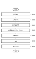
- fixation fine movement is mainly composed of three components (fine movement components) (see FIG. 4).
- Tremore Frequency component of 30 to 100Hz at a viewing angle of about 50 °
- Flick Step-like or pulse-like motion with a viewing angle of about 20 ° that occurs irregularly (interval of 0.03 to 5 seconds)
- Drift Low-speed motion with a viewing angle of about 10 'or less existing between flicks
- Patent Document 3 and Patent Document 4 disclose apparatuses having tracking means for moving the irradiation position of the measurement light beam onto the measurement site in real time in response to fixation fine movement.
- the present invention has been made in view of the above problems, and provides an imaging control technique capable of suppressing the influence of eye movements when imaging a fundus tomographic image.
- An imaging control apparatus is an imaging control apparatus that controls imaging means for imaging a tomographic image of the fundus of the subject eye, Obtaining means for obtaining information indicating the direction of fundus movement of the eye to be examined; Analysis means for analyzing the direction of the fundus movement based on the information acquired by the acquisition means; Control means for controlling the photographing means so that the direction of photographing by the photographing means matches the direction of the fundus movement based on the analysis result of the analyzing means.
- an imaging control technique capable of suppressing the influence of eye movements when imaging a fundus tomographic image.
- the accompanying drawings are included in the specification, constitute a part thereof, show an embodiment of the present invention, and are used to explain the principle of the present invention together with the description.
- 1 is a diagram illustrating a functional configuration of a control device 1 of a fundus tomography apparatus according to a first embodiment.
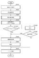
- 3 is a flowchart showing a processing procedure of the control device 1 of the fundus tomography apparatus according to the first embodiment.
- 1 is a diagram illustrating a functional configuration of a wide-area image capturing apparatus 2 according to a first embodiment.
- FIG. 1 is a diagram illustrating a functional configuration of a tomographic image capturing apparatus 3 according to a first embodiment.
- FIG. The figure explaining a scanning motion when imaging a tomogram.
- the figure which shows the example of a display together with the wide area image which concerns on 1st Embodiment, and the acquisition range of a tomogram.
- 6 is a flowchart showing a processing procedure for fundus movement analysis according to the first embodiment.
- FIG. 3 is a diagram illustrating an example of a wide area image according to the first embodiment.
- 6 is a flowchart showing a processing procedure for shooting parameter setting according to the first embodiment.
- FIG. 5 is a diagram showing a relationship between a fundus movement direction and a transversal scan direction according to the first embodiment.
- the flowchart which shows the process sequence of the control apparatus 1 of the fundus tomography apparatus according to the fourth embodiment.
- FIG. 1 is a diagram schematically showing a device configuration that constitutes a diagnostic system according to an embodiment of the present invention.
- a fundus tomographic imaging apparatus that captures a tomographic image of the fundus of the subject's eye has a control device 1.
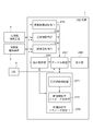
- the control device 1 includes a central processing unit (CPU) 100, a main memory 101, a magnetic disk 102, a control program 103, a display memory 104, a monitor 105, a mouse 106, a keyboard 107, and a common bus 108.
- CPU central processing unit
- the central processing unit (CPU) 100 mainly controls the operation of each component of the control device 1 (imaging control device).
- the main memory 101 can store a device control program and function as a work area when executing the program.
- the magnetic disk 102 stores an operating system (OS), a device drive of a peripheral device, a control program 103 (hereinafter also simply referred to as “program”) for performing various processes to be described later, and the like.
- the display memory 104 can temporarily store (store) display data.
- the monitor 105 is a CRT monitor or a liquid crystal monitor, for example, and displays an image based on data from the display memory 104.
- a mouse 106 and a keyboard 107 are used for a pointing input and a character input by a user.
- the above components are connected to each other by a common bus 108.
- a control device 1 of a fundus tomographic imaging apparatus is connected to a wide area imaging apparatus 2 and a tomographic imaging apparatus 3 via a local area network (LAN) 4 such as Ethernet. Connected. Note that these devices may be connected via an external interface such as USB or IEEE1394.
- LAN local area network
- the wide-area image capturing apparatus 2 is an apparatus that captures a wide-area image of the eye, and includes, for example, a fundus camera or a scanning laser ophthalmoscope (SLO).
- SLO scanning laser ophthalmoscope
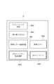
- FIG. 5 shows a functional configuration when the wide-area imaging device 2 is a scanning laser ophthalmoscope (SLO).
- the wide-area image capturing apparatus 2 controls the polygon mirror 520 and the galvanometer mirror 530 via the scanning drive mechanism 510 in order to capture a wide-area image of the eye.
- the reflected light of the weak laser light emitted from the imaging light source 500 is received by the light receiving element 540 configured by, for example, a CCD, so that a wide area image of the eye is captured.
- the SLO device configuration and drive mechanism control are described in detail in Patent Document 2.
- Patent Document 1 an example in which an image of a fundus camera is used as the wide area image capturing apparatus will be described.
- the details of the configuration of the device equipped with the fundus camera and the control of the drive mechanism are described in detail in Patent Document 1.
- the tomographic imaging apparatus 3 is an apparatus that captures a tomographic image of the eye, and includes, for example, a time domain optical coherence tomography (OCT) or a Fourier domain optical coherence tomography (OCT).
- FIG. 6 shows a functional configuration when the tomographic imaging apparatus 3 is a time domain optical coherence tomography (OCT).
- a parameter for instructing the content of imaging is input from the control apparatus 1 of the fundus tomographic imaging apparatus, and tomographic imaging is executed using the input parameter.
- the obtained tomogram is output to the control device 1 of the fundus tomography apparatus.
- the parameters that specify the contents of imaging are the tomographic image acquisition site and position, the spatial range of the tomographic image, the level of detail such as the scan line (A scan) interval, the scan order (traversal scan) and the scan direction
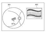
- FIG. 7 shows an example of a fundus image 701 obtained from the wide-area image capturing device 2 and an example of a tomographic image 702 of the retina obtained from the tomographic image capturing device 3.
- 701a indicates the position of the tomographic image 702.
- the tomographic image 702 is composed of a scan line (also called A scan) 703 that scans the depth direction of a plurality of retinas.
- a scan line is run on the retina to construct a tomographic image.
- Reference numerals 704 and 704a indicate the traveling. This traveling may also be called traversal scan or main traveling. Furthermore, when continuously capturing tomographic images, the shooting travel is represented by 705 or 705a. This traveling may be referred to as auxiliary traveling.
- the tomographic imaging apparatus 3 controls the reference mirror driving mechanism 601 and the galvano mirror driving mechanism 603 according to these parameters, and drives the reference mirror 602 and the galvano mirror 604. Then, the reflected light of the light emitted from the low-coherence light source 600 is received by a light receiving element 605 configured by, for example, a CCD, so that a tomographic image of the eye is captured.
- a light receiving element 605 configured by, for example, a CCD
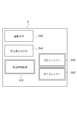
- FIG. 2 is a functional block diagram of the control device 1 of the fundus tomography apparatus according to the present embodiment.
- the fundus tomography apparatus control apparatus 1 includes an eye information acquisition unit 210, a wide-area image acquisition unit 220, a tomographic image acquisition unit 230, an instruction acquisition unit 240, a data storage unit 250, a display unit 260, A tomographic image acquisition parameter processing unit 270 is provided.
- the eye information acquisition unit 210 acquires information for identifying the eye to be examined from the outside.
- the information for identifying the eye to be examined is, for example, an identification number assigned to each eye to be examined.
- the identification number of the subject and an identifier indicating whether the examination target is the right eye or the left eye may be used in combination.
- it includes ecological information such as patient age and medical history.
- Information for identifying the eye to be examined is input by the operator. If the tomographic imaging apparatus 3 holds information for identifying the eye to be examined, the information may be acquired from the tomographic imaging apparatus 3 together with the tomographic image.
- the eye information acquisition unit 210 further acquires information about the eye to be inspected held by the magnetic disk 102 based on information for identifying the eye to be inspected.
- the instruction acquisition unit 240 functions as a setting unit that receives setting of imaging parameters for obtaining a tomographic image of the fundus oculi, and acquires an instruction of processing input by the operator using the mouse 106, the keyboard 107, and the like. For example, imaging parameters for obtaining a fundus tomographic image such as a fundus tomographic image capturing position and an imaging range are acquired. Alternatively, an instruction to start imaging, an initial parameter of tomographic image acquisition parameters, an instruction on whether to save an acquired tomographic image, an instruction on a storage location, and the like are acquired. The content of the instruction acquired by the instruction acquisition unit 240 is transmitted to the wide-area image acquisition unit 220, the tomographic image acquisition unit 230, the data storage unit 250, the display unit 260, and the tomographic image acquisition parameter processing unit 270 as necessary.
- the wide-area image acquisition unit 220 requests the wide-area image capturing device 2 to capture and transmit a wide-area image of the eye based on the instruction acquired by the instruction acquisition unit 240, and Get a wide-area image.
- the wide area image acquired by the wide area image acquisition unit 220 is transmitted to the tomographic image acquisition parameter processing unit 270, the display unit 260, and the data storage unit 250.
- Tomographic image acquisition unit 230 Based on the instruction acquired by the instruction acquiring unit 240, the tomographic image acquiring unit 230 transmits a tomographic image capturing request to the tomographic image capturing apparatus 3 together with a parameter indicating the imaging content determined by the tomographic image acquisition parameter setting unit 272. To do. Then, a tomographic image transmitted from the tomographic imaging apparatus 3 is acquired. The tomographic image acquired by the tomographic image acquisition unit 230 is transmitted to the display unit 260 and the data storage unit 250.
- the tomographic image acquisition parameter processing unit 270 includes a fundus motion analysis unit 271 and a tomographic image acquisition parameter setting unit 272.
- the imaging parameters for instructing the contents of imaging determined by the tomographic image acquisition parameter processing unit 270 are scanning methods such as a tomographic image acquisition site and position, a tomographic spatial range, a scan line interval, a scanning order, a scanning speed and a scanning direction. It is a parameter to indicate.
- the fundus motion analysis unit 271 analyzes the wide-area image acquired by the wide-area image acquisition unit 220, and calculates information on the fixation movement (the direction of drift, the movement range of drift and tremore, the interval and the moment when the flick occurs). Then, the analysis result is transmitted to the tomogram acquisition parameter setting unit 272, the display unit 260, and the data storage unit 250. Details of specific processing for analyzing fundus movement will be described in detail later. In the present embodiment, an example in which fundus movement information is obtained by analyzing a fundus wide area image will be described, but the method for obtaining fundus movement information is not limited.
- the movement of the fundus may be estimated by analyzing an image obtained by photographing the anterior eye part (cornea, pupil, iris), or by detecting the movement of the eyeball known in the line-of-sight input device. It is also possible to estimate movement.
- the tomographic image acquisition parameter setting unit 272 generates a captured image based on the eye information acquired by the eye information acquisition unit 210, the instruction information acquired by the instruction acquisition unit 240, and the fundus movement information obtained from the fundus movement analysis unit 271. Parameters relating to acquisition of tomographic images (imaging parameters of tomographic images) that minimize the influence of fundus movement (fixation micromotion) are set. The details of the specific processing for setting the tomographic imaging parameters based on the result of the fundus oculi analysis unit 271 will be described in detail later.
- the imaging parameters set by the tomographic image acquisition parameter processing unit 270 are transmitted to the tomographic image acquisition unit 230, the display unit 260, and the data storage unit 250.
- the data storage unit 250 associates various types of input information and stores the information as certain patient data in the magnetic disk 102. Specifically, the to-be-examined eye information input from the to-be-examined eye information acquisition unit 210, the wide-area image input from the wide-area image acquisition unit 220, the imaging parameters of the tomographic image input from the tomographic-image acquisition parameter processing unit 270, the tomographic image acquisition unit The tomographic image input from 230 is saved. Further, the data may be stored in an external server (not shown). In this case, the data storage unit 250 transmits these data to the external server.
- the display unit 260 displays the wide area image acquired by the wide area image acquisition unit 220 and the tomographic image acquired by the tomographic image acquisition unit 230 on the monitor 105.
- the imaging parameters of the tomographic image set by the tomographic image acquisition parameter processing unit 270 are displayed. If a tomographic image cannot be acquired, information indicating that is displayed. Further, in order to confirm the order of scanning (traversal scan), scanning direction, scanning speed, imaging position and range, a fundus wide area image may be presented together.
- step S310 the instruction acquisition unit 240 acquires shooting instruction information for the fundus of the subject.
- the imaging instruction for example, an instruction such as designation of a region or position on the fundus for acquiring a wide area image or tomographic image, an imaging range, and the like is acquired from the outside.
- This instruction is input by the operator via the keyboard 107 and the mouse 106.
- the obtained instruction is transmitted to the wide area image acquisition unit 220, the tomographic image acquisition parameter processing unit 270, and the data storage unit 250.
- step S320 the wide-area image acquisition unit 220 requests the wide-area image capturing apparatus 2 to capture and transmit a wide-area image of the eye, and acquires the wide-area image of the eye transmitted from the wide-area image capturing apparatus 2. Then, the acquired wide-area image is transmitted to the fundus motion analysis unit 271, the display unit 260, and the data storage unit 250.
- step S320 detailed settings for parameters (number of images, shutter speed) when acquiring a wide area image will be described later.
- step S330 the fundus motion analysis unit 271 performs image processing on the wide area image acquired in step S320, and detects information regarding fundus motion.
- the fundus movement analysis unit 271 in the present embodiment detects the amount of movement and the direction of movement of fixation micromotion performed unconsciously as the movement of the fundus.
- the motion blur motion blur or motion blur
- the optical flow detection process of the wide area image is analyzed or detected by the optical flow detection process of the wide area image. The contents of each specific process will be described in detail later.
- step S340 the tomographic image acquisition parameter setting unit 272 sets a traversal scan direction and speed for tomographic image acquisition based on the fundus motion information detected in step S330. Further, a parameter for instructing the content of tomographic image capturing is set based on the instruction information acquired in step 310. For example, parameters such as the tomographic image capturing position on the fundus and the image capturing range. Then, the result is transmitted to the tomographic image acquisition unit 230, the display unit 260, and the data storage unit 250.
- the tomographic imaging time is set based on the amount of fixation micromotion movement, and the tomographic traversal scan is based on the movement direction information on fixation micromotion. Set the direction. The specific processing contents of each setting will be described in detail later.
- step S350 the tomogram acquisition unit 230 acquires a tomogram from the tomogram imaging device 3 based on the tomogram imaging parameters set in step S340. That is, a tomographic imaging request is transmitted to the tomographic imaging apparatus 3 together with a parameter for instructing the imaging content. Then, a tomographic image transmitted from the tomographic imaging apparatus 3 is acquired. The tomographic image acquired by the tomographic image acquisition unit 230 is transmitted to the display unit 260 and the data storage unit 250. Note that, when imaging at a plurality of positions is instructed in step S340, an imaging request using each imaging parameter is transmitted to the tomographic imaging apparatus 3, and imaging is performed a plurality of times.
- step S360 the display unit 260 displays the tomographic image obtained in step S350 on the monitor 105.
- the wide area image and the acquisition range of the tomographic image on the wide area image may be presented together.
- the imaging parameters of the tomographic image may be displayed together.
- FIG. 8 is a display example thereof. In this example, a wide area image 801 and a tomographic image acquisition range 801a are displayed on the left side, and a tomographic image 802 acquired on the upper right side. 801a also indicates the direction of traversal scan and the imaging position intervals of multiple tomographic images (processing in step S370).
- step S370 the data storage unit 250 associates the various types of information input in the above steps and stores the information as certain patient data in the magnetic disk 102. Specifically, the imaging instruction information obtained in step S310, the wide-area image obtained in step S320, the fundus motion analysis obtained in step S330, the tomographic imaging parameters obtained in step S340, and obtained in step S3350. Preserved tomographic images. Of course, the data to be stored need not be all of these.
- data may be stored in an external server (not shown).
- the data storage unit 250 transmits these data to the external server.
- the fundus motion is estimated using the property that blurring or blurring (motion blur) appears in the captured image when the subject moves during shooting.
- the fundus momentum and direction are estimated using two wide-area images with different shutter speeds.
- the image generation model of blur (motion blur) in the wide-area image B that appears due to the movement of the fundus is estimated by estimating the PSF parameters using Point Spread Function (PSF: point spread function), Estimate the amount and direction of motion blur.
- PSF Point Spread Function
- the image g (x, y) with motion blur is modeled as a convolution integral of the image f (x, y) without blur and PSFp (x, y).
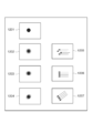
- the movement of the fundus is not only a one-way movement, but also a non-directional movement (tremor) in addition to a directional movement (drift, flick). Can be represented in multiple directions (see FIG. 12).
- FIG. 14 is a diagram for explaining parameters of Point Spread Function for modeling motion blur.
- x and y are the positions from the target pixel
- r is the size in the direction where the movement amount of the motion blur is small
- l and ⁇ are the sizes and directions in the direction where the movement amount of the motion blur is large.
- r, l, and ⁇ are PSF parameters.
- an image without motion blur and a certain image are obtained.
- a motion blur image is generated with various r, l, and ⁇ parameters from an image without motion blur.
- the most similar image of the captured motion blur image is searched from the generated motion blur image, and the PSF parameter of the similar generated image is set as the PSF parameter of the captured motion blur image.
- step S910 a fundus image with a fast shutter speed is acquired from the wide-area image capturing device 2 via the wide-area image acquisition unit 220.
- the shutter speed is set to, for example, seconds in order to avoid blurring due to flicks and drifts that have a large momentum of fixation fine movement.
- tremor moves at a frequency of 30Hz to 100Hz, so this shutter speed is not enough to avoid the effects of tremor.
- the momentum of tremore itself is smaller than that of flick and drift, tremor is ignored in this embodiment, but a faster shutter speed that can avoid the influence of tremore may be used.
- 1010 in FIG. 10 shows an example of a wide area image having a high shutter speed.
- a wide area image taken at a high shutter speed is hereinafter referred to as “wide area image A”.
- step S920 a fundus image with a slow shutter speed is obtained from the wide-area image capturing device 2 via the wide-area image acquisition unit 220.
- the shutter speed is set to, for example, seconds.
- the movement of the fixation may cause the fundus to move with a movement range of 0.1 to 0.5 mm per second.
- a 15 mm x 15 mm area of the fundus is captured with an image of 1024 x 1024 pixels, the fundus moves 7 to 35 pixels on the image at a shutter speed of seconds, resulting in a blur of that width.
- the image size, shooting area, and shutter speed of the wide area image are not limited to the above-described examples, and may be different from those in the present embodiment as long as the movement of the fundus appears as a blur in the captured image.
- 1020 in FIG. 10 shows an example of a wide area image with a slow shutter speed.
- a wide-area image taken at a slow shutter speed is hereinafter referred to as “wide-area image B”.
- step S930 the wide area image A without (or few) motion blur is set to f (x, y) and convolved with PSFp (x, y) of various r, l, and ⁇ parameters. To do. Then, an image (g (x, y)) with motion blur of each r, l, ⁇ parameter is generated.
- an image may be generated in a range of m max ⁇ l ⁇ r ⁇ m min .
- m max and mmin may be obtained from the instruction acquisition unit 240 or may be values stored in the data storage unit 250 in advance.
- the convolution process it is not necessary to perform the convolution process on the entire wide area image A, and some areas of the wide area image A to be the attention area, for example, the operator's instruction acquired by the instruction acquisition unit 240 or the area to be tomographic image target. It may be a target.
- step S940 the PSF image of various r, l, and ⁇ parameters generated from the wide area image A is compared with the image of the wide area image B, and an image most similar to the wide area image B is searched.
- a fixed wide-area image capturing time is taken as an example for the sake of explanation, but it may be changed according to the eye information obtained from the eye information acquisition unit 210. For example, it is known that the amount of movement of the fundus increases with age. Furthermore, in order to make the analysis more accurate, it is possible to take a wide-area image at a plurality of photographing times and perform the analysis.
- the method for estimating the movement amount and the movement direction of the fundus using the PSF having various parameters has been described.
- the present embodiment is not limited to this method.
- Non-Patent Document 1 and Non-Patent Document 2 introduce in detail a motion blur estimation method using Point Spread Function (related to point spread).
- Non-Patent Document 3 introduces a method for estimating the amount and direction of motion blur by analyzing the Fourier space of an image.
- step S330 is executed.
- step S340 the tomographic imaging time and the tomographic transversal scan direction are set based on the fundus motion estimation result obtained in step S330.
- step S1110 the tomographic imaging time is determined based on the result of the estimation of the fundus motion obtained in step S340, and the speed of the transverse scan and the imaging range are set.
- the momentum is large, the tomographic image must be captured in a shorter time in order to reduce the influence on the tomographic image capturing.
- the momentum is small, it is expected that the influence on the tomographic image is small, and the tomographic image can be captured in a longer time.
- the interval between the tomographic image and the tomographic image is 31.5 ⁇ m.
- the interval since the interval is affected by the fundus movement, the interval may be shifted. Since it takes 12.8 ⁇ ⁇ ms (minimum) to start taking one tomographic image after taking one tomographic image, if it is estimated in step S330 that the fundus moves 250 ⁇ m per second, The relative displacement of the tomographic image is 6.4 ⁇ m. This will result in an error of about 20% from the expected interval.
- the shooting time should be reduced.
- the Transversal scan is twice as fast (936 mm / s), and the imaging area can be taken with 128 256-pixel wide tomographic images.
- the time interval between tomograms is 6.4 ms, and the relative positional deviation between tomograms is 3.2 ⁇ m with the same fundus momentum.
- the size per pixel in the transversal scan direction is 23.44 ⁇ m.
- the error for calculating the shooting time may be obtained from the instruction acquisition unit 240, or may be a parameter that is already determined and stored in the data storage unit 250.
- the explanation is made that the imaging time is halved.
- the imaging time is determined as follows based on the tomographic imaging area, the number of tomographic images, the amount of movement of the fundus, and the specified error. Can be easy.
- the imaging area is reduced without reducing the sampling density (sampling period). It is also possible. As in the above example, in order to halve the error, the imaging area may be halved (3 x 2 mm square) at the same transversal scan speed. In this case, whether to give priority to the tomographic region or the sampling density (sampling period) is the purpose of the inspection (examination, precise inspection, etc.) obtained from the instruction acquisition unit 240, or the direct operator You may. For example, in the case of medical examination, since a wide range of examination is desirable, it is possible to prioritize the area and lower the sampling density (sampling period).
- step S1120 the direction of the transversal scan can be determined by the movement direction of the fundus movement obtained in step S340.
- FIG. 12 is a diagram showing the relationship between the fundus movement direction and the transversal scan direction.
- reference numeral 1201 denotes an example of a wide area image A taken at a high shutter speed.
- 1202 shows an example of a wide area image B taken with a slow shutter.
- the outline is blurred due to the influence of microscopic tremors, the direction of blur is the same in every direction, and no directionality is seen.
- the example of the wide-area image B at 1203 strongly represents the blur in the horizontal direction.
- 1204 of FIG. 12 the wide area image B is strongly blurred in a direction inclined by 45 degrees.
- step S340 the process of step S340 is executed.
- the direction and speed of the tomographic transversal scan using the image blur amount and direction analysis result of the fundus wide area image By determining the imaging region, it is possible to obtain a tomographic image with little influence of the fundus movement.
- step S330 in the fundus motion analysis unit 271 is analyzed based on the image blur (motion blur) of the wide area image B.
- the gist of the present invention is limited to the example. is not.
- fundus motion analysis is performed based on the optical flow of a wide area image. A processing procedure in the fundus motion analysis unit 271 will be described below.
- the region information of the fundus that is to be imaged for tomographic images is acquired from the instruction acquisition unit 240.
- a plurality of continuous wide-area images with a time interval in the area to be imaged are obtained.
- set the shutter speed for shooting fast eg, seconds
- Set the shooting time interval to 30 images / second.
- a scanning laser ophthalmoscope SLO may be used as the wide-area image capturing device 2 as described above.
- step 330 the optical flow between the wide area images is calculated.
- a region of interest is determined for a wide area image (for example, 128 ⁇ 128 pixels), and the same pattern is searched for in adjacent frames by a pattern matching method or the like.
- pattern matching sum of squares difference (SSD) may be used.
- the attention area that becomes the pattern is searched for the position where the SSD is minimized with respect to the adjacent tomographic image.
- the movement amount and movement direction of the corresponding attention area correspond to the movement amount and movement direction of the fundus movement.
- fundus motion information can be acquired by performing motion flow analysis of the wide-area image. .
- the direction, speed, or imaging area of the transversal scan of tomographic imaging is set by analyzing the fundus motion.
- a better setting of the tomographic imaging start time will be described by fundus motion analysis.
- fixation tremor consists of three movements (tremore, drift, and flick).
- Tremor The amount of exercise is small, the movement is fast and always occurs.
- Drift The momentum is large and the movement is slow and always occurs.
- a flick is a fundus movement that occurs at a certain time interval within a measurement time for measuring the fundus movement.
- a tendency of a time interval at which a flick occurs is detected, and when a flick is detected, tomographic imaging is started, and a tomographic parameter setting for ending tomographic imaging is performed before the next flick occurs.
- the fundus motion analysis unit 271 analyzes the wide-area image acquired by the wide-area image acquisition unit 220 and calculates the interval and instant at which the flick occurs.
- the movement of the fundus is detected from a wide area image taken continuously in time. Then, when motion flow of a wide area image of the adjacent fundus occurs momentarily (larger than average), this is set as a flick. A plurality of flicks are detected while measuring the time, and an average time interval at which the flicks occur is calculated.
- a tomographic imaging start command is sent to the tomographic imaging device via the tomographic image acquisition unit 230 when the next flick occurs, and the imaging time is the average of the flicks Set a typical shooting interval.
- an average time interval is used for the shooting time, but it is not limited to this setting criterion, and it may be set based on a minimum time interval or a criterion based on a time interval distribution, or an instruction acquisition.
- the time interval may be set based on other criteria such as an instruction from the operator acquired by the unit 240.
- a temporal probability distribution that causes a flick of the eye to be examined is obtained, for example, as shown in FIG. 15, it may be a time corresponding to T25 at which a flick does not occur with a probability of 25%. Further, in addition to flicking, if the eye of the subject's eye blinks when the eyelid of the subject's eye appears in the wide-area image, the influence of the blink on the tomographic image can be reduced in the same manner.
- FIG. 13 a specific processing procedure executed by the control device 1 of the fundus tomography apparatus according to this embodiment will be described. Note that description of steps that are common to the processing procedure of FIG. 3 already described is omitted.
- step S1310 the tomographic image acquisition parameters set in step S340 are checked to determine whether the parameters satisfy the conditions.
- the shooting instruction obtained in step S310 can be used.
- the shooting instruction includes a shooting range.
- step S340 The tomographic image acquisition parameters set in step S340 are confirmed (S1310), and if they are determined to be valid parameters, the process proceeds to step S350, and a tomographic image is acquired.
- step S1320 a warning indicating that the tomographic image acquisition parameter set in step S340 is not a valid parameter is displayed on the display unit 260.
- a warning lamp can be turned on or a buzzer can be sounded.
- the determination criteria are not limited to the case where the shooting range is halved or the parameter setting is set to 3/4, but there may be other conditions. As an example of other conditions for giving a warning, the movement of the fundus oculi is too large and the imaging time must be extremely shortened. However, the number of samplings is too small and an effective tomographic image cannot be obtained.
- step S1330 the photographing instructor is requested to confirm whether or not to continue photographing.
- step S1330 it is determined whether or not to continue shooting based on an input from the shooting instruction person.
- the process proceeds to step S350, and a tomographic image is acquired. If the shooting is not continued, the process proceeds to step 370, where necessary information is stored, and the entire process is terminated.
- a warning is output when an effective tomographic image acquisition parameter cannot be obtained, a determination is made by an imaging instruction person, and an invalid tomographic image is obtained when imaging is not continued. Can be avoided.
- the present invention can also be realized by executing the following processing. That is, software (program) that realizes the functions of the above-described embodiments is supplied to a system or apparatus via a network or various storage media, and the computer (or CPU, MPU, etc.) of the system or apparatus reads the program. It is a process to be executed.
Abstract
An imaging control device for controlling an imaging unit for capturing a tomogram of an eye ground of the subject under optometry includes an acquiring unit for acquiring information indicating the direction of the eye ground movement of the subject, an analyzing unit for analyzing the direction of the eye ground movement on the basis of the acquired information, and a control unit for controlling the imaging unit so that the direction of the eye ground movement based on the result of the analysis agrees with the direction in which the imaging unit captures the tomogram.
Description
本発明は、撮影制御装置、撮影装置、撮影制御方法、プログラム、記憶媒体に関する。
The present invention relates to a photographing control device, a photographing device, a photographing control method, a program, and a storage medium.
生活習慣病や失明原因の上位を占める各種疾病の早期診断を目的として、眼部の検査が広く行われている。検診等においては眼部全体における疾病を見つけることが求められるため、眼部の広い範囲にわたる像(以下、広域像と呼ぶ)を用いた検査が必須となる。広域像は、例えば、眼底カメラや走査型レーザー検眼鏡(SLO;Scanning Laser Ophthalmoscope)を用いて撮像される。
眼 Eye examinations are widely performed for the purpose of early diagnosis of lifestyle diseases and various diseases that account for the top causes of blindness. In medical examinations and the like, since it is required to find a disease in the entire eye part, an examination using an image over a wide range of the eye part (hereinafter referred to as a wide area image) is essential. The wide area image is captured using, for example, a fundus camera or a scanning laser ophthalmoscope (SLO).
一方、光干渉断層計(OCT;Optical Coherence Tomography)などの眼部の断層像取得装置は疾病の状態を客観的尺度で定量化することが可能であり、疾病の診断をより的確に行うのに有用であると期待されている。一般的なOCTでは、撮像者が断層像の撮像パラメータ(例えば、対象部位、撮像範囲、詳細度、走査方法など)を決定し、その撮像パラメータに基づいて眼部の局所領域のみが撮像・解析される。
On the other hand, ophthalmic tomogram acquisition devices such as optical coherence tomography (OCT; Optical Coherence Tomography) can quantify the state of the disease on an objective scale, making it more accurate to diagnose the disease. Expected to be useful. In general OCT, the imager determines tomographic imaging parameters (for example, target region, imaging range, level of detail, scanning method, etc.), and only the local region of the eye is imaged and analyzed based on the imaging parameters. Is done.
撮像者による断層像の撮像を支援する技術として、例えば、特許文献1には、眼底カメラによる広域像上においてOCTによる断層像の撮像範囲を指示するユーザインタフェースに関する技術が開示されている。また特許文献2には、SLOによる広域像上においてOCTによる断層像の撮像範囲を指定するユーザインタフェースに関する技術が開示されている。特許文献1や特許文献2によれば、眼底の広域像の様子を参照しながら断層像の撮像範囲を決定できるので、撮像パラメータの設定が比較的容易となる。
For example, Patent Document 1 discloses a technique related to a user interface that indicates a tomographic imaging range by OCT on a wide-area image by a fundus camera as a technique for supporting imaging of a tomographic image by an imager. Patent Document 2 discloses a technique related to a user interface for designating an imaging range of a tomographic image by OCT on a wide area image by SLO. According to Patent Document 1 and Patent Document 2, the imaging range of a tomographic image can be determined while referring to the state of a wide area image of the fundus, so that it is relatively easy to set imaging parameters.
ただし、人間の眼は、固定された点を注視していても無意識に絶えず、固視微動という微小な運動を行う。固視微動は、主に3つの成分(微動成分)から成ると知られている(図4を参照)。
However, the human eye constantly moves unconsciously, even when gazing at a fixed point, and performs a minute movement called microscopic fixation. It is known that fixation fine movement is mainly composed of three components (fine movement components) (see FIG. 4).
(1)トレモア:視角50°程度で30~100Hzの周波数成分
(2)フリック:不規則(0.03~5秒間隔)に生じる視角20°程度のステップ状やパルス状の運動
(3)ドリフト:フリックの間に存在する視角10’以下程度の低速の運動
光干渉断層計(OCT)による測定処理時間内は測定部位に対して測定光ビームが正確に当たっている必要があるが、実際には被検眼の固視微動等があるために、測定部位に測定光ビームを正確に当て続けることは困難である。 (1) Tremore: Frequency component of 30 to 100Hz at a viewing angle of about 50 ° (2) Flick: Step-like or pulse-like motion with a viewing angle of about 20 ° that occurs irregularly (interval of 0.03 to 5 seconds) (3) Drift : Low-speed motion with a viewing angle of about 10 'or less existing between flicks During the measurement processing time by optical coherence tomography (OCT), the measurement light beam needs to hit the measurement site accurately. It is difficult to keep the measurement light beam accurately applied to the measurement site because there is a fine movement of the optometry.
特許文献3、特許文献4には、固視微動に対応して実時間で測定光ビームの照射位置を測定部位上に移動させるトラッキング手段を有する装置が開示されている。
Patent Document 3 and Patent Document 4 disclose apparatuses having tracking means for moving the irradiation position of the measurement light beam onto the measurement site in real time in response to fixation fine movement.
手動で撮像パラメータを指定して断層像の撮像を行う場合、撮影直前の被検眼の固視微動状況がわからなく、測定時間を減らして固視微動の影響を抑えることも考えられる。この場合、測定点数(サンプリング数)も減らしてしまうので、固視微動の影響を最小限に抑える撮像パラメータを適切に設定するのは容易ではないという課題がある。
When performing tomographic imaging by manually specifying imaging parameters, it is also possible to suppress the influence of fixation micromotion by reducing the measurement time because the fixation micromotion state of the subject's eye immediately before imaging is unknown. In this case, since the number of measurement points (sampling number) is also reduced, there is a problem that it is not easy to appropriately set the imaging parameters that minimize the influence of fixation micromotion.
また、特許文献3及び特許文献4の技術を用いた場合、固視微動を検出しながらOCT撮影の補正を行うことで固視微動の影響を抑えることができる。この場合、予め設定されたtraversal scan速度と方向で撮影を行うので、被検眼毎の撮影時の固視微動の特性に合わせたtraversal scan速度と方向の撮影設定を行わない。トラッキング機能を搭載するには測定ビームとトラッキングビームを同時に放射を行わなければならないので装置は複雑になるという課題がある。
Further, when the techniques of Patent Literature 3 and Patent Literature 4 are used, the influence of fixation micromotion can be suppressed by correcting OCT imaging while detecting fixation micromotion. In this case, since imaging is performed at a preset traversal scan speed and direction, imaging settings for the traversal scan speed and direction are not performed in accordance with the characteristics of fixation micromotion at the time of imaging for each eye to be examined. In order to mount the tracking function, since the measurement beam and the tracking beam must be emitted simultaneously, there is a problem that the apparatus becomes complicated.
本発明は、上記の課題に鑑みてなされたものであり、眼底断層像を撮影する時の眼球運動の影響を抑えることが可能な撮影制御技術を提供する。
The present invention has been made in view of the above problems, and provides an imaging control technique capable of suppressing the influence of eye movements when imaging a fundus tomographic image.
本発明にかかる撮影制御装置は、被検眼者の眼底の断層像を撮影する撮影手段を制御する撮影制御装置であって、
前記被検眼者の眼底運動の方向を示す情報を取得する取得手段と、
前記取得手段により取得された前記情報に基づき、前記眼底運動の方向を解析する解析手段と、
前記解析手段の解析結果に基づく前記眼底運動の方向に、前記撮影手段が撮影する方向を合わせるように、前記撮影手段を制御する制御手段と、を備える。 An imaging control apparatus according to the present invention is an imaging control apparatus that controls imaging means for imaging a tomographic image of the fundus of the subject eye,
Obtaining means for obtaining information indicating the direction of fundus movement of the eye to be examined;
Analysis means for analyzing the direction of the fundus movement based on the information acquired by the acquisition means;
Control means for controlling the photographing means so that the direction of photographing by the photographing means matches the direction of the fundus movement based on the analysis result of the analyzing means.
本発明によれば、眼底断層像を撮影する時の眼球運動の影響を抑えることが可能な撮影制御技術の提供が可能になる。
According to the present invention, it is possible to provide an imaging control technique capable of suppressing the influence of eye movements when imaging a fundus tomographic image.
本発明のその他の特徴及び利点は、添付図面を参照とした以下の説明により明らかになるであろう。なお、添付図面においては、同じ若しくは同様の構成には、同じ参照番号を付す。
Other features and advantages of the present invention will become apparent from the following description with reference to the accompanying drawings. In the accompanying drawings, the same or similar components are denoted by the same reference numerals.
添付図面は明細書に含まれ、その一部を構成し、本発明の実施の形態を示し、その記述と共に本発明の原理を説明するために用いられる。
第1実施形態に係る眼底断層像撮影装置の制御装置1の構成を示す図。
第1実施形態に係る眼底断層像撮影装置の制御装置1の機能的構成を示す図。
第1実施形態に係る眼底断層像撮影装置の制御装置1の処理手順を示すフローチャート。
眼底の運動である固視微動の3つの成分を示す図。
第1実施形態に係る広域像撮像装置2の機能構成を示す図。
第1実施形態に係る断層像撮像装置3の機能構成を示す図。
断層像を撮影する際にスキャン運動を説明する図。
第1実施形態に係る広域像と、断層像の取得範囲を一緒に表示例を示す図。
第1実施形態に係る眼底運動解析の処理手順を示すフローチャート。
第1実施形態に係る広域像の例を示す図。
第1実施形態に係る撮影パラメータ設定の処理手順を示すフローチャート。
第1実施形態に係る眼底の運動方向とtransversal scanの方向の関係を示す図。
第4実施形態に係る眼底断層像撮影装置の制御装置1の処理手順を示すフローチャート。
第1実施形態に係るモーションブラーをモデル化するためのPoint Spread Functionのパラメータを説明するための図。
第3実施形態に係るフリックが起こる確率分布を例示する図。
The accompanying drawings are included in the specification, constitute a part thereof, show an embodiment of the present invention, and are used to explain the principle of the present invention together with the description.
The figure which shows the structure of the control apparatus 1 of the fundus tomography apparatus according to the first embodiment. 1 is a diagram illustrating a functional configuration of a control device 1 of a fundus tomography apparatus according to a first embodiment. 3 is a flowchart showing a processing procedure of the control device 1 of the fundus tomography apparatus according to the first embodiment. The figure which shows three components of the fixation fine movement which is a movement of the fundus. 1 is a diagram illustrating a functional configuration of a wide-area image capturing apparatus 2 according to a first embodiment. 1 is a diagram illustrating a functional configuration of a tomographic image capturing apparatus 3 according to a first embodiment. FIG. The figure explaining a scanning motion when imaging a tomogram. The figure which shows the example of a display together with the wide area image which concerns on 1st Embodiment, and the acquisition range of a tomogram. 6 is a flowchart showing a processing procedure for fundus movement analysis according to the first embodiment. FIG. 3 is a diagram illustrating an example of a wide area image according to the first embodiment. 6 is a flowchart showing a processing procedure for shooting parameter setting according to the first embodiment. FIG. 5 is a diagram showing a relationship between a fundus movement direction and a transversal scan direction according to the first embodiment. The flowchart which shows the process sequence of the control apparatus 1 of the fundus tomography apparatus according to the fourth embodiment. The figure for demonstrating the parameter of Point Spread Function for modeling the motion blur based on 1st Embodiment. The figure which illustrates the probability distribution in which the flick which concerns on 3rd Embodiment occurs.
以下、図面を参照して、本発明の好適な実施形態を例示的に詳しく説明する。ただし、この実施の形態に記載されている構成要素はあくまで例示であり、本発明の技術的範囲は、特許請求の範囲によって確定されるのであって、以下の個別の実施形態によって限定されるわけではない。
Hereinafter, exemplary embodiments of the present invention will be described in detail with reference to the drawings. However, the constituent elements described in this embodiment are merely examples, and the technical scope of the present invention is determined by the claims, and is limited by the following individual embodiments. is not.
(第1実施形態)
まず本実施の形態の構成を説明する。図1は、本発明の実施形態に係る診断システムを構成する機器構成を概略的に示す図である。被検眼者の眼底の断層像を撮影する眼底断層像撮影装置は制御装置1を有する。制御装置1は、中央処理装置(CPU)100、主メモリ101、磁気ディスク102、制御プログラム103、表示メモリ104、モニタ105、マウス106、キーボード107、共通バス108を含んでいる。 (First embodiment)
First, the configuration of the present embodiment will be described. FIG. 1 is a diagram schematically showing a device configuration that constitutes a diagnostic system according to an embodiment of the present invention. A fundus tomographic imaging apparatus that captures a tomographic image of the fundus of the subject's eye has acontrol device 1. The control device 1 includes a central processing unit (CPU) 100, a main memory 101, a magnetic disk 102, a control program 103, a display memory 104, a monitor 105, a mouse 106, a keyboard 107, and a common bus 108.
まず本実施の形態の構成を説明する。図1は、本発明の実施形態に係る診断システムを構成する機器構成を概略的に示す図である。被検眼者の眼底の断層像を撮影する眼底断層像撮影装置は制御装置1を有する。制御装置1は、中央処理装置(CPU)100、主メモリ101、磁気ディスク102、制御プログラム103、表示メモリ104、モニタ105、マウス106、キーボード107、共通バス108を含んでいる。 (First embodiment)
First, the configuration of the present embodiment will be described. FIG. 1 is a diagram schematically showing a device configuration that constitutes a diagnostic system according to an embodiment of the present invention. A fundus tomographic imaging apparatus that captures a tomographic image of the fundus of the subject's eye has a
中央処理装置(CPU)100は、主として、制御装置1(撮影制御装置)の各構成要素の動作を制御する。主メモリ101は、装置制御プログラムを格納したり、プログラム実行時の作業領域として機能することが可能である。磁気ディスク102は、オペレーティングシステム(OS)、周辺機器のデバイスドライブ、後述する各種の処理を行うための制御プログラム103(以下、単に「プログラム」ともいう。)等を格納する。表示メモリ104は、表示用データを一時的に記憶(格納)することが可能である。モニタ105は、たとえばCRTモニタや液晶モニタであり、表示メモリ104からのデータに基づいて画像を表示する。マウス106及びキーボード107はユーザによるポインティング入力及び文字等の入力を各々行う。上記各構成要素は共通バス108により互いに接続される。
The central processing unit (CPU) 100 mainly controls the operation of each component of the control device 1 (imaging control device). The main memory 101 can store a device control program and function as a work area when executing the program. The magnetic disk 102 stores an operating system (OS), a device drive of a peripheral device, a control program 103 (hereinafter also simply referred to as “program”) for performing various processes to be described later, and the like. The display memory 104 can temporarily store (store) display data. The monitor 105 is a CRT monitor or a liquid crystal monitor, for example, and displays an image based on data from the display memory 104. A mouse 106 and a keyboard 107 are used for a pointing input and a character input by a user. The above components are connected to each other by a common bus 108.
図1に示すように、眼底断層像撮影装置(撮影装置)の制御装置1は、広域像撮像装置2及び断層像撮像装置3と、イーサネット等によるローカル・エリア・ネットワーク(LAN)4を介して接続される。なお、これらの機器の接続は、USBやIEEE1394等の外部インタフェースを介して行ってもよい。
As shown in FIG. 1, a control device 1 of a fundus tomographic imaging apparatus (imaging apparatus) is connected to a wide area imaging apparatus 2 and a tomographic imaging apparatus 3 via a local area network (LAN) 4 such as Ethernet. Connected. Note that these devices may be connected via an external interface such as USB or IEEE1394.
広域像撮像装置2は、眼部の広域像を撮像する装置であり、例えば眼底カメラや走査型レーザー検眼鏡(SLO)からなる。
The wide-area image capturing apparatus 2 is an apparatus that captures a wide-area image of the eye, and includes, for example, a fundus camera or a scanning laser ophthalmoscope (SLO).
図5に、広域像撮像装置2が走査型レーザー検眼鏡(SLO)である場合の機能構成を示す。図5に示すように、広域像撮像装置2は眼部の広域像を撮像するために、走査駆動機構510を介してポリゴンミラー520及びガルバノミラー530の制御を行う。そして、撮影光源500から照射された微弱なレーザー光の反射光が、例えば、CCDなどにより構成される受光素子540で受光されることにより、眼部の広域像が撮像される。なお、SLOの機器構成や駆動機構制御の詳細は、特許文献2に詳しく述べられている。本実施形態では、広域像撮像装置として眼底カメラの画像を利用した例を説明する。眼底カメラを搭載した機器構成や駆動機構制御の詳細は特許文献1に詳しく述べられている。
FIG. 5 shows a functional configuration when the wide-area imaging device 2 is a scanning laser ophthalmoscope (SLO). As shown in FIG. 5, the wide-area image capturing apparatus 2 controls the polygon mirror 520 and the galvanometer mirror 530 via the scanning drive mechanism 510 in order to capture a wide-area image of the eye. Then, the reflected light of the weak laser light emitted from the imaging light source 500 is received by the light receiving element 540 configured by, for example, a CCD, so that a wide area image of the eye is captured. Details of the SLO device configuration and drive mechanism control are described in detail in Patent Document 2. In this embodiment, an example in which an image of a fundus camera is used as the wide area image capturing apparatus will be described. The details of the configuration of the device equipped with the fundus camera and the control of the drive mechanism are described in detail in Patent Document 1.
断層像撮像装置3は、眼部の断層像を撮像する装置であり、例えば、タイムドメイン方式の光干渉断層計(OCT)やフーリエドメイン方式の光干渉断層計(OCT)からなる。図6に、断層像撮像装置3がタイムドメイン方式の光干渉断層計(OCT)である場合の機能構成を示す。断層像撮像装置3において、撮像の内容を指示するパラメータは、眼底断層像撮影装置の制御装置1から入力され、入力されたパラメータを用いて断層像の撮像が実行される。そして、得られた断層像は眼底断層像撮影装置の制御装置1へと出力される。
The tomographic imaging apparatus 3 is an apparatus that captures a tomographic image of the eye, and includes, for example, a time domain optical coherence tomography (OCT) or a Fourier domain optical coherence tomography (OCT). FIG. 6 shows a functional configuration when the tomographic imaging apparatus 3 is a time domain optical coherence tomography (OCT). In the tomographic imaging apparatus 3, a parameter for instructing the content of imaging is input from the control apparatus 1 of the fundus tomographic imaging apparatus, and tomographic imaging is executed using the input parameter. The obtained tomogram is output to the control device 1 of the fundus tomography apparatus.
ここで、撮像の内容を指示するパラメータとは、断層像の取得部位や位置、断層像の空間的範囲、スキャンライン(A scan)間隔などの詳細度、走査(traversal scan)順や走査方向、走査速度といった走査法を指示するパラメータである。図7は、広域像撮像装置2から得られる眼底像701の例と、断層像撮像装置3から得られる網膜の断層像702の例を示す。701aは、断層像702の位置を示している。図7の例では、断層像702は、複数の網膜の奥行き方向をスキャンするスキャンライン(A scanとも呼ばれる)703で構成される。一枚の断層像を構成するために網膜上でスキャンラインを走行させる。704および704aは、その走行を示す。この走行は、traversal scanまたは、主走行とも呼ぶことがある。さらに、連続的に断層像を撮像するときに、その撮影走行は705または705aで表している。この走行は副走行と呼ぶことがある。
Here, the parameters that specify the contents of imaging are the tomographic image acquisition site and position, the spatial range of the tomographic image, the level of detail such as the scan line (A scan) interval, the scan order (traversal scan) and the scan direction This is a parameter for instructing a scanning method such as a scanning speed. FIG. 7 shows an example of a fundus image 701 obtained from the wide-area image capturing device 2 and an example of a tomographic image 702 of the retina obtained from the tomographic image capturing device 3. 701a indicates the position of the tomographic image 702. In the example of FIG. 7, the tomographic image 702 is composed of a scan line (also called A scan) 703 that scans the depth direction of a plurality of retinas. A scan line is run on the retina to construct a tomographic image. Reference numerals 704 and 704a indicate the traveling. This traveling may also be called traversal scan or main traveling. Furthermore, when continuously capturing tomographic images, the shooting travel is represented by 705 or 705a. This traveling may be referred to as auxiliary traveling.
断層像撮像装置3は、これらのパラメータに従って参照ミラー駆動機構601及びガルバノミラー駆動機構603を制御し、参照ミラー602及びガルバノミラー604を駆動する。そして、低コヒーレンス光源600から照射された光の反射光は、例えば、CCDなどで構成される受光素子605で受光されることにより、眼部の断層像が撮像される。なお、断層像撮像装置3がフーリエドメイン方式の光干渉断層計(OCT)からなる場合、ガルバノミラー604のみが制御される。なお、これらのOCTの機器構成や駆動機構の制御に関する詳細は、特許文献1や特許文献2に詳しく述べられている。
The tomographic imaging apparatus 3 controls the reference mirror driving mechanism 601 and the galvano mirror driving mechanism 603 according to these parameters, and drives the reference mirror 602 and the galvano mirror 604. Then, the reflected light of the light emitted from the low-coherence light source 600 is received by a light receiving element 605 configured by, for example, a CCD, so that a tomographic image of the eye is captured. Note that when the tomographic imaging apparatus 3 includes a Fourier domain optical coherence tomography (OCT), only the galvanometer mirror 604 is controlled. Details regarding the configuration of these OCT devices and the control of the drive mechanism are described in detail in Patent Document 1 and Patent Document 2.
次に、図2を用いて、眼底断層像撮影装置の制御装置1の機能構成を説明する。図2は本実施形態における眼底断層像撮影装置の制御装置1の機能ブロック図である。図2に示す通り、眼底断層像撮影装置の制御装置1は、被検眼情報取得部210、広域像取得部220、断層像取得部230、指示取得部 240、データ保存部250、表示部260、断層像取得パラメータ処理部270、を備えて構成される。
Next, the functional configuration of the control device 1 of the fundus tomography apparatus will be described with reference to FIG. FIG. 2 is a functional block diagram of the control device 1 of the fundus tomography apparatus according to the present embodiment. As shown in FIG. 2, the fundus tomography apparatus control apparatus 1 includes an eye information acquisition unit 210, a wide-area image acquisition unit 220, a tomographic image acquisition unit 230, an instruction acquisition unit 240, a data storage unit 250, a display unit 260, A tomographic image acquisition parameter processing unit 270 is provided.
(被検眼情報取得部210)
被検眼情報取得部210は、被検眼を同定する情報を外部から取得する。ここで、被検眼を同定する情報とは、例えば、夫々の被検眼に割りあてられた識別番号である。なお、これ以外に、被検眼を同定する情報として、被検者の識別番号と、検査対象が右眼であるか左眼であるかを表す識別子を組み合わせて用いてもよい。さらに、患者の年齢、病歴などの生態的情報を含む。 (Examination eye information acquisition unit 210)
The eyeinformation acquisition unit 210 acquires information for identifying the eye to be examined from the outside. Here, the information for identifying the eye to be examined is, for example, an identification number assigned to each eye to be examined. In addition to this, as the information for identifying the eye to be examined, the identification number of the subject and an identifier indicating whether the examination target is the right eye or the left eye may be used in combination. In addition, it includes ecological information such as patient age and medical history.
被検眼情報取得部210は、被検眼を同定する情報を外部から取得する。ここで、被検眼を同定する情報とは、例えば、夫々の被検眼に割りあてられた識別番号である。なお、これ以外に、被検眼を同定する情報として、被検者の識別番号と、検査対象が右眼であるか左眼であるかを表す識別子を組み合わせて用いてもよい。さらに、患者の年齢、病歴などの生態的情報を含む。 (Examination eye information acquisition unit 210)
The eye
被検眼を同定する情報は、操作者によって入力される。なお、被検眼を同定する情報を断層像撮像装置3が保持している場合には、断層像と共にこの情報を断層像撮像装置3から取得する構成としてもよい。被検眼情報取得部210は、さらに、被検眼を同定する情報に基づいて、磁気ディスク102が保持している当該被検眼に関する情報を取得する。
Information for identifying the eye to be examined is input by the operator. If the tomographic imaging apparatus 3 holds information for identifying the eye to be examined, the information may be acquired from the tomographic imaging apparatus 3 together with the tomographic image. The eye information acquisition unit 210 further acquires information about the eye to be inspected held by the magnetic disk 102 based on information for identifying the eye to be inspected.
(指示取得部240)
指示取得部240は、眼底の断層像を得るための撮影パラメータの設定を受け付ける設定手段として機能し、マウス106やキーボード107などを用いて操作者が入力する処理の指示を取得する。例えば、眼底断層像の撮影位置や、撮影範囲、などの眼底断層像を得るための撮影パラメータを取得する。または、撮影の開始の指示や、断層像取得パラメータの初期パラメータ、撮影された断層像を保存するか否かの指示や保存場所の指示等を取得する。指示取得部240が取得した指示の内容は、必要に応じて広域像取得部220、断層像取得部230、データ保存部250、表示部260、断層像取得パラメータ処理部270へと送信される。 (Instruction acquisition unit 240)
Theinstruction acquisition unit 240 functions as a setting unit that receives setting of imaging parameters for obtaining a tomographic image of the fundus oculi, and acquires an instruction of processing input by the operator using the mouse 106, the keyboard 107, and the like. For example, imaging parameters for obtaining a fundus tomographic image such as a fundus tomographic image capturing position and an imaging range are acquired. Alternatively, an instruction to start imaging, an initial parameter of tomographic image acquisition parameters, an instruction on whether to save an acquired tomographic image, an instruction on a storage location, and the like are acquired. The content of the instruction acquired by the instruction acquisition unit 240 is transmitted to the wide-area image acquisition unit 220, the tomographic image acquisition unit 230, the data storage unit 250, the display unit 260, and the tomographic image acquisition parameter processing unit 270 as necessary.
指示取得部240は、眼底の断層像を得るための撮影パラメータの設定を受け付ける設定手段として機能し、マウス106やキーボード107などを用いて操作者が入力する処理の指示を取得する。例えば、眼底断層像の撮影位置や、撮影範囲、などの眼底断層像を得るための撮影パラメータを取得する。または、撮影の開始の指示や、断層像取得パラメータの初期パラメータ、撮影された断層像を保存するか否かの指示や保存場所の指示等を取得する。指示取得部240が取得した指示の内容は、必要に応じて広域像取得部220、断層像取得部230、データ保存部250、表示部260、断層像取得パラメータ処理部270へと送信される。 (Instruction acquisition unit 240)
The
(広域像取得部220)
広域像取得部220は、指示取得部240が取得した指示に基づいて、広域像撮像装置2に眼部の広域像の撮像と送信を要求し、広域像撮像装置2から送信される眼部の広域像を取得する。広域像取得部220が取得した広域像は、断層像取得パラメータ処理部270、表示部260、及びデータ保存部250へと送信される。 (Wide-area image acquisition unit 220)
The wide-areaimage acquisition unit 220 requests the wide-area image capturing device 2 to capture and transmit a wide-area image of the eye based on the instruction acquired by the instruction acquisition unit 240, and Get a wide-area image. The wide area image acquired by the wide area image acquisition unit 220 is transmitted to the tomographic image acquisition parameter processing unit 270, the display unit 260, and the data storage unit 250.
広域像取得部220は、指示取得部240が取得した指示に基づいて、広域像撮像装置2に眼部の広域像の撮像と送信を要求し、広域像撮像装置2から送信される眼部の広域像を取得する。広域像取得部220が取得した広域像は、断層像取得パラメータ処理部270、表示部260、及びデータ保存部250へと送信される。 (Wide-area image acquisition unit 220)
The wide-area
(断層像取得部230)
断層像取得部230は、指示取得部240が取得した指示に基づいて、断層像取得パラメータ設定部272が定めた撮像の内容を指示するパラメータと共に断層像の撮像要求を断層像撮像装置3に送信する。そして、断層像撮像装置3から送信される断層像を取得する。断層像取得部230が取得した断層像は、表示部260、及びデータ保存部250へと送信される。 (Tomographic image acquisition unit 230)
Based on the instruction acquired by theinstruction acquiring unit 240, the tomographic image acquiring unit 230 transmits a tomographic image capturing request to the tomographic image capturing apparatus 3 together with a parameter indicating the imaging content determined by the tomographic image acquisition parameter setting unit 272. To do. Then, a tomographic image transmitted from the tomographic imaging apparatus 3 is acquired. The tomographic image acquired by the tomographic image acquisition unit 230 is transmitted to the display unit 260 and the data storage unit 250.
断層像取得部230は、指示取得部240が取得した指示に基づいて、断層像取得パラメータ設定部272が定めた撮像の内容を指示するパラメータと共に断層像の撮像要求を断層像撮像装置3に送信する。そして、断層像撮像装置3から送信される断層像を取得する。断層像取得部230が取得した断層像は、表示部260、及びデータ保存部250へと送信される。 (Tomographic image acquisition unit 230)
Based on the instruction acquired by the
(断層像取得パラメータ処理部270)
断層像取得パラメータ処理部270は、眼底運動解析部 271と断層像取得パラメータ設定部272によって構成される。断層像取得パラメータ処理部270が定める撮像の内容を指示する撮影パラメータは、断層像の取得部位や位置、断層像の空間的範囲、スキャンライン間隔、走査順、走査速度や走査方向といった走査法を指示するパラメータである。 (Tomographic image acquisition parameter processing unit 270)
The tomographic image acquisitionparameter processing unit 270 includes a fundus motion analysis unit 271 and a tomographic image acquisition parameter setting unit 272. The imaging parameters for instructing the contents of imaging determined by the tomographic image acquisition parameter processing unit 270 are scanning methods such as a tomographic image acquisition site and position, a tomographic spatial range, a scan line interval, a scanning order, a scanning speed and a scanning direction. It is a parameter to indicate.
断層像取得パラメータ処理部270は、眼底運動解析部 271と断層像取得パラメータ設定部272によって構成される。断層像取得パラメータ処理部270が定める撮像の内容を指示する撮影パラメータは、断層像の取得部位や位置、断層像の空間的範囲、スキャンライン間隔、走査順、走査速度や走査方向といった走査法を指示するパラメータである。 (Tomographic image acquisition parameter processing unit 270)
The tomographic image acquisition
眼底運動解析部 271は、広域像取得部220が取得した広域像を解析し、固視微動に関する情報(ドリフトの方向、ドリフトとトレモアの移動範囲、フリックが起きる間隔や瞬間)の算出を行う。そして、断層像取得パラメータ設定部272、表示部260及びデータ保存部250へと解析結果を送信する。なお、眼底運動を解析する具体的処理の内容に関しては、後に詳しく説明する。本実施形態では、眼底の広域像の解析により眼底運動情報を得る例を説明するが眼底運動情報を得る方法として限定することではない。例えば、前眼部(角膜や瞳孔、虹彩)を撮影して撮影された画像の解析によって眼底の運動を推定することもよいし、視線入力装置で知られている眼球の運動検出方法によって眼底の運動を推定することも良い。
The fundus motion analysis unit 271 analyzes the wide-area image acquired by the wide-area image acquisition unit 220, and calculates information on the fixation movement (the direction of drift, the movement range of drift and tremore, the interval and the moment when the flick occurs). Then, the analysis result is transmitted to the tomogram acquisition parameter setting unit 272, the display unit 260, and the data storage unit 250. Details of specific processing for analyzing fundus movement will be described in detail later. In the present embodiment, an example in which fundus movement information is obtained by analyzing a fundus wide area image will be described, but the method for obtaining fundus movement information is not limited. For example, the movement of the fundus may be estimated by analyzing an image obtained by photographing the anterior eye part (cornea, pupil, iris), or by detecting the movement of the eyeball known in the line-of-sight input device. It is also possible to estimate movement.
断層像取得パラメータ設定部272は被検眼情報取得部210が取得した被検眼情報や、指示取得部240が取得した指示情報や、眼底運動解析部271から得られる眼底運動情報に基づき、撮像画像に眼底運動(固視微動)の影響を最も少なくする断層像の取得に関するパラメータ(断層像の撮像パラメータ)を設定する。なお、眼底運動解析部 271の結果に基づいて断層像の撮像パラメータを設定する具体的処理の内容に関しては、後に詳しく説明する。
The tomographic image acquisition parameter setting unit 272 generates a captured image based on the eye information acquired by the eye information acquisition unit 210, the instruction information acquired by the instruction acquisition unit 240, and the fundus movement information obtained from the fundus movement analysis unit 271. Parameters relating to acquisition of tomographic images (imaging parameters of tomographic images) that minimize the influence of fundus movement (fixation micromotion) are set. The details of the specific processing for setting the tomographic imaging parameters based on the result of the fundus oculi analysis unit 271 will be described in detail later.
断層像取得パラメータ処理部270によって設定された撮像パラメータは、断層像取得部230、表示部260、及びデータ保存部250へと送信される。
The imaging parameters set by the tomographic image acquisition parameter processing unit 270 are transmitted to the tomographic image acquisition unit 230, the display unit 260, and the data storage unit 250.
(データ保存部250)
データ保存部250は、入力した各種の情報を関連付けて、ある患者のデータとして磁気ディスク102へと保存する。具体的には、被検眼情報取得部210から入力された被検眼情報、広域像取得部220から入力した広域像、断層像取得パラメータ処理部270から入力した断層像の撮像パラメータ、断層像取得部230から入力した断層像を保存する。また、データの保存は不図示の外部サーバに行ってもよく、この場合、データ保存部250はこれらのデータを外部サーバへと送信する。 (Data storage unit 250)
Thedata storage unit 250 associates various types of input information and stores the information as certain patient data in the magnetic disk 102. Specifically, the to-be-examined eye information input from the to-be-examined eye information acquisition unit 210, the wide-area image input from the wide-area image acquisition unit 220, the imaging parameters of the tomographic image input from the tomographic-image acquisition parameter processing unit 270, the tomographic image acquisition unit The tomographic image input from 230 is saved. Further, the data may be stored in an external server (not shown). In this case, the data storage unit 250 transmits these data to the external server.
データ保存部250は、入力した各種の情報を関連付けて、ある患者のデータとして磁気ディスク102へと保存する。具体的には、被検眼情報取得部210から入力された被検眼情報、広域像取得部220から入力した広域像、断層像取得パラメータ処理部270から入力した断層像の撮像パラメータ、断層像取得部230から入力した断層像を保存する。また、データの保存は不図示の外部サーバに行ってもよく、この場合、データ保存部250はこれらのデータを外部サーバへと送信する。 (Data storage unit 250)
The
(表示部260)
表示部260は、広域像取得部220で取得された広域像や断層像取得部230により得られた断層像を、モニタ105に表示する。また、断層像取得パラメータ処理部270が設定した断層像の撮像パラメータを表示する。また、断層像の取得ができなかった場合には、その旨を表す情報を表示する。さらに、走査(traversal scan)順や走査方向、走査速度、撮影位置と範囲を確認するために、眼底の広域像を一緒に提示しても良い。 (Display unit 260)
Thedisplay unit 260 displays the wide area image acquired by the wide area image acquisition unit 220 and the tomographic image acquired by the tomographic image acquisition unit 230 on the monitor 105. In addition, the imaging parameters of the tomographic image set by the tomographic image acquisition parameter processing unit 270 are displayed. If a tomographic image cannot be acquired, information indicating that is displayed. Further, in order to confirm the order of scanning (traversal scan), scanning direction, scanning speed, imaging position and range, a fundus wide area image may be presented together.
表示部260は、広域像取得部220で取得された広域像や断層像取得部230により得られた断層像を、モニタ105に表示する。また、断層像取得パラメータ処理部270が設定した断層像の撮像パラメータを表示する。また、断層像の取得ができなかった場合には、その旨を表す情報を表示する。さらに、走査(traversal scan)順や走査方向、走査速度、撮影位置と範囲を確認するために、眼底の広域像を一緒に提示しても良い。 (Display unit 260)
The
次に、図3を参照して、本実施形態の眼底断層像撮影装置の制御装置1により実行される、具体的な処理の手順を説明する。なお、本実施形態における制御装置1の各部の機能は、各部の機能を実現するプログラムをCPU100が実行し、コンピュータ全体を制御することで実現される。なお、以下の処理を行う前段で、同フローチャートに従ったプログラムコードは、例えば、磁気ディスク102から主メモリ101に既にロードされているものとする。
Next, a specific processing procedure executed by the control device 1 of the fundus tomography apparatus according to the present embodiment will be described with reference to FIG. In addition, the function of each part of the control apparatus 1 in this embodiment is implement | achieved when CPU100 runs the program which implement | achieves the function of each part, and controls the whole computer. It is assumed that the program code according to the flowchart is already loaded from the magnetic disk 102 to the main memory 101, for example, before the following processing is performed.
(ステップS310の処理)
ステップS310において、指示取得部240は、被験者の眼底に対する撮影の指示情報を取得する。撮影指示として、例えば、広域像取得または断層像取得対象の眼底上の部位や位置の指定や、撮影範囲、などの指示を外部から取得する。この指示は、キーボード107やマウス106を介して、操作者によって入力される。得られた指示は、広域像取得部220、断層像取得パラメータ処理部270、データ保存部250へと送信される。 (Processing of step S310)
In step S310, theinstruction acquisition unit 240 acquires shooting instruction information for the fundus of the subject. As the imaging instruction, for example, an instruction such as designation of a region or position on the fundus for acquiring a wide area image or tomographic image, an imaging range, and the like is acquired from the outside. This instruction is input by the operator via the keyboard 107 and the mouse 106. The obtained instruction is transmitted to the wide area image acquisition unit 220, the tomographic image acquisition parameter processing unit 270, and the data storage unit 250.
ステップS310において、指示取得部240は、被験者の眼底に対する撮影の指示情報を取得する。撮影指示として、例えば、広域像取得または断層像取得対象の眼底上の部位や位置の指定や、撮影範囲、などの指示を外部から取得する。この指示は、キーボード107やマウス106を介して、操作者によって入力される。得られた指示は、広域像取得部220、断層像取得パラメータ処理部270、データ保存部250へと送信される。 (Processing of step S310)
In step S310, the
(ステップS320の処理)
ステップS320において、広域像取得部220は、広域像撮像装置2に眼部の広域像の撮像と送信を要求し、広域像撮像装置2から送信される眼部の広域像を取得する。そして、取得した広域像を、眼底運動解析部271、表示部260、及びデータ保存部250へと送信する。 (Processing of step S320)
In step S320, the wide-areaimage acquisition unit 220 requests the wide-area image capturing apparatus 2 to capture and transmit a wide-area image of the eye, and acquires the wide-area image of the eye transmitted from the wide-area image capturing apparatus 2. Then, the acquired wide-area image is transmitted to the fundus motion analysis unit 271, the display unit 260, and the data storage unit 250.
ステップS320において、広域像取得部220は、広域像撮像装置2に眼部の広域像の撮像と送信を要求し、広域像撮像装置2から送信される眼部の広域像を取得する。そして、取得した広域像を、眼底運動解析部271、表示部260、及びデータ保存部250へと送信する。 (Processing of step S320)
In step S320, the wide-area
ステップS320では、広域像を取得時のパラメータ(画像の枚数、シャッター速度)などについの詳細設定は、後述に説明する。
In step S320, detailed settings for parameters (number of images, shutter speed) when acquiring a wide area image will be described later.
(ステップS330の処理)
ステップS330において、眼底運動解析部271は、ステップS320で取得した広域像に画像処理を施し、眼底運動に関する情報を検出する。本実施形態における眼底運動解析部271は、眼底の運動として、無意識で行われる固視微動の運動量と運動方向を検出する。固視微動の運動量と運動方向を検出するために、ステップS320で取得した広域像のモーションブラー(motion blur または運動ボケ)を解析し、あるいは広域像のoptical flow検出処理によって検出される。それぞれの具体的処理の内容に関しては、後に詳しく説明する。 (Processing of step S330)
In step S330, the fundusmotion analysis unit 271 performs image processing on the wide area image acquired in step S320, and detects information regarding fundus motion. The fundus movement analysis unit 271 in the present embodiment detects the amount of movement and the direction of movement of fixation micromotion performed unconsciously as the movement of the fundus. In order to detect the momentum and direction of fixation fine movement, the motion blur (motion blur or motion blur) of the wide area image acquired in step S320 is analyzed or detected by the optical flow detection process of the wide area image. The contents of each specific process will be described in detail later.
ステップS330において、眼底運動解析部271は、ステップS320で取得した広域像に画像処理を施し、眼底運動に関する情報を検出する。本実施形態における眼底運動解析部271は、眼底の運動として、無意識で行われる固視微動の運動量と運動方向を検出する。固視微動の運動量と運動方向を検出するために、ステップS320で取得した広域像のモーションブラー(motion blur または運動ボケ)を解析し、あるいは広域像のoptical flow検出処理によって検出される。それぞれの具体的処理の内容に関しては、後に詳しく説明する。 (Processing of step S330)
In step S330, the fundus
(ステップS340の処理)
ステップS340において、断層像取得パラメータ設定部272は、ステップS330で検出した眼底の運動情報に基づいて、断層像取得のためのtraversal scanの方向と速度を設定する。さらに、ステップ310で取得された指示情報にも基づいて断層像の撮像の内容を指示するパラメータを設定する。例えば、眼底上での断層像の撮影位置や、撮影範囲等のパラメータである。そして、その結果を断層像取得部230、表示部260、及びデータ保存部250へと送信する。断層像の撮影に固視微動の影響を減らすために、固視微動の移動量を元に、断層像の撮影時間を設定し、固視微動の移動方向情報を元に、断層像のtraversal scanの方向を設定する。それぞれの設定の具体的処理の内容に関しては、後に詳しく説明する。 (Processing of step S340)
In step S340, the tomographic image acquisitionparameter setting unit 272 sets a traversal scan direction and speed for tomographic image acquisition based on the fundus motion information detected in step S330. Further, a parameter for instructing the content of tomographic image capturing is set based on the instruction information acquired in step 310. For example, parameters such as the tomographic image capturing position on the fundus and the image capturing range. Then, the result is transmitted to the tomographic image acquisition unit 230, the display unit 260, and the data storage unit 250. In order to reduce the influence of fixation micromotion on tomographic imaging, the tomographic imaging time is set based on the amount of fixation micromotion movement, and the tomographic traversal scan is based on the movement direction information on fixation micromotion. Set the direction. The specific processing contents of each setting will be described in detail later.
ステップS340において、断層像取得パラメータ設定部272は、ステップS330で検出した眼底の運動情報に基づいて、断層像取得のためのtraversal scanの方向と速度を設定する。さらに、ステップ310で取得された指示情報にも基づいて断層像の撮像の内容を指示するパラメータを設定する。例えば、眼底上での断層像の撮影位置や、撮影範囲等のパラメータである。そして、その結果を断層像取得部230、表示部260、及びデータ保存部250へと送信する。断層像の撮影に固視微動の影響を減らすために、固視微動の移動量を元に、断層像の撮影時間を設定し、固視微動の移動方向情報を元に、断層像のtraversal scanの方向を設定する。それぞれの設定の具体的処理の内容に関しては、後に詳しく説明する。 (Processing of step S340)
In step S340, the tomographic image acquisition
(ステップS350の処理)
ステップS350において、断層像取得部230は、ステップS340で設定された断層像の撮像パラメータに基づき、断層像撮像装置3から断層像を取得する。すなわち、撮像の内容を指示するパラメータと共に断層像の撮像要求を断層像撮像装置3に送信する。そして、断層像撮像装置3から送信される断層像を取得する。断層像取得部230が取得した断層像は、表示部260、及びデータ保存部250へと送信される。なお、ステップS340で複数の位置に関する撮像が指示された場合には、夫々の撮像パラメータを用いた撮像要求を断層像撮像装置3に送信し、複数回の撮像を実行する。 (Processing of step S350)
In step S350, thetomogram acquisition unit 230 acquires a tomogram from the tomogram imaging device 3 based on the tomogram imaging parameters set in step S340. That is, a tomographic imaging request is transmitted to the tomographic imaging apparatus 3 together with a parameter for instructing the imaging content. Then, a tomographic image transmitted from the tomographic imaging apparatus 3 is acquired. The tomographic image acquired by the tomographic image acquisition unit 230 is transmitted to the display unit 260 and the data storage unit 250. Note that, when imaging at a plurality of positions is instructed in step S340, an imaging request using each imaging parameter is transmitted to the tomographic imaging apparatus 3, and imaging is performed a plurality of times.
ステップS350において、断層像取得部230は、ステップS340で設定された断層像の撮像パラメータに基づき、断層像撮像装置3から断層像を取得する。すなわち、撮像の内容を指示するパラメータと共に断層像の撮像要求を断層像撮像装置3に送信する。そして、断層像撮像装置3から送信される断層像を取得する。断層像取得部230が取得した断層像は、表示部260、及びデータ保存部250へと送信される。なお、ステップS340で複数の位置に関する撮像が指示された場合には、夫々の撮像パラメータを用いた撮像要求を断層像撮像装置3に送信し、複数回の撮像を実行する。 (Processing of step S350)
In step S350, the
(ステップS360の処理)
ステップS360において、表示部260は、ステップS350で得られた断層像を、モニタ105上に表示する。ここで撮像部位の確認等の理由で、広域像と、広域像上でにおける断層像の取得範囲を一緒に提示してもよい。また、断層像の撮像パラメータを合わせて表示してもよい。図8は、その表示例である。この例では、左側に広域像801と断層像の取得範囲801a、右上に取得された断層像802が表示されている。801aは、traversal scanの方向と、複数の断層像の撮影位置間隔も示している
(ステップS370の処理)
ステップS370において、データ保存部250は、以上のステップで入力した各種の情報を関連付けて、ある患者のデータとして磁気ディスク102へと保存する。具体的には、ステップS310で取得された撮影の指示情報、ステップS320で得た広域像、ステップS330で得た眼底運動解析の結果、ステップS340で得た断層像の撮像パラメータ、ステップS3350で得た断層像とを保存する。もちろん、保存するデータはこれらの全てでなくてもよい。 (Processing of step S360)
In step S360, thedisplay unit 260 displays the tomographic image obtained in step S350 on the monitor 105. Here, for reasons such as confirmation of the imaging region, the wide area image and the acquisition range of the tomographic image on the wide area image may be presented together. Further, the imaging parameters of the tomographic image may be displayed together. FIG. 8 is a display example thereof. In this example, a wide area image 801 and a tomographic image acquisition range 801a are displayed on the left side, and a tomographic image 802 acquired on the upper right side. 801a also indicates the direction of traversal scan and the imaging position intervals of multiple tomographic images (processing in step S370).
In step S370, thedata storage unit 250 associates the various types of information input in the above steps and stores the information as certain patient data in the magnetic disk 102. Specifically, the imaging instruction information obtained in step S310, the wide-area image obtained in step S320, the fundus motion analysis obtained in step S330, the tomographic imaging parameters obtained in step S340, and obtained in step S3350. Preserved tomographic images. Of course, the data to be stored need not be all of these.
ステップS360において、表示部260は、ステップS350で得られた断層像を、モニタ105上に表示する。ここで撮像部位の確認等の理由で、広域像と、広域像上でにおける断層像の取得範囲を一緒に提示してもよい。また、断層像の撮像パラメータを合わせて表示してもよい。図8は、その表示例である。この例では、左側に広域像801と断層像の取得範囲801a、右上に取得された断層像802が表示されている。801aは、traversal scanの方向と、複数の断層像の撮影位置間隔も示している
(ステップS370の処理)
ステップS370において、データ保存部250は、以上のステップで入力した各種の情報を関連付けて、ある患者のデータとして磁気ディスク102へと保存する。具体的には、ステップS310で取得された撮影の指示情報、ステップS320で得た広域像、ステップS330で得た眼底運動解析の結果、ステップS340で得た断層像の撮像パラメータ、ステップS3350で得た断層像とを保存する。もちろん、保存するデータはこれらの全てでなくてもよい。 (Processing of step S360)
In step S360, the
In step S370, the
なお、データの保存は不図示の外部サーバに行ってもよく、この場合、データ保存部250はこれらのデータを外部サーバへと送信する。
Note that data may be stored in an external server (not shown). In this case, the data storage unit 250 transmits these data to the external server.
(眼底運動解析処理)
次に、図9を参照して、ステップS330で実行される眼底運動解析処理の手順を説明する。本実施形態では、撮影時に被写体が動くと撮像画像にブレやボケ(モーションブラー)が現れる性質を利用して、眼底の運動を推定する。そのために、シャッター速度の異なる2つの広域像の利用して、眼底の運動量と方向を推定する。 (Fundus motion analysis processing)
Next, with reference to FIG. 9, the procedure of the fundus oculi movement analysis process executed in step S330 will be described. In the present embodiment, the fundus motion is estimated using the property that blurring or blurring (motion blur) appears in the captured image when the subject moves during shooting. For this purpose, the fundus momentum and direction are estimated using two wide-area images with different shutter speeds.
本実施形態では、眼底の運動により現れる広域像Bでのボケ(モーションブラー)の画像生成モデルには、Point Spread Function (PSF:点広がり関数)を用いて、PSFのパラメータを推定することで、運動ブレ量と方向を推定する。
In this embodiment, the image generation model of blur (motion blur) in the wide-area image B that appears due to the movement of the fundus is estimated by estimating the PSF parameters using Point Spread Function (PSF: point spread function), Estimate the amount and direction of motion blur.
モーションブラーのある画像g(x、y)は、ボケのない画像f(x、y)とPSFp(x、y)の畳み込み積分としてモデル化する。
The image g (x, y) with motion blur is modeled as a convolution integral of the image f (x, y) without blur and PSFp (x, y).
g(x、y)=f(x、y)*p(x、y)
眼底の運動は、すでに説明したように、一方向の運動だけでなく、方向性のある運動(ドリフト、フリック)の他に方向性のない運動(トレモア)があるので、広域像Bに現れるボケは、複数方向で表わすことができる(図12を参照)。 g (x, y) = f (x, y) * p (x, y)
As described above, the movement of the fundus is not only a one-way movement, but also a non-directional movement (tremor) in addition to a directional movement (drift, flick). Can be represented in multiple directions (see FIG. 12).
本実施形態では、次の式でモーションブラーのPSFを近似する(図14を参照)。図14は、モーションブラーをモデル化するためのPoint Spread Functionのパラメータを説明するための図である。
In this embodiment, the motion blur PSF is approximated by the following equation (see FIG. 14). FIG. 14 is a diagram for explaining parameters of Point Spread Function for modeling motion blur.

ここで、xとyとは注目画素からの位置、rはモーションブラーの移動量の少ない方向での大きさ;lとθとはモーションブラーの移動量の多い方向の大きさと方向を示す。本実施形態では、r、l、θをPSFのパラメータとする。
Here, x and y are the positions from the target pixel, r is the size in the direction where the movement amount of the motion blur is small; and l and θ are the sizes and directions in the direction where the movement amount of the motion blur is large. In this embodiment, r, l, and θ are PSF parameters.
ここでは、PSFのr、l、θを推定するために、モーションブラーのない画像とある画像を得る。モーションブラーのない画像からモーションブラー画像をいろいろなr、l、θパラメータで生成する。生成されたモーションブラー画像から、撮影されたモーションブラー画像の一番類似する画像を探索し、類似する生成された画像のPSFパラメータを、撮影されたモーションブラー画像のPSFパラメータとする。
Here, in order to estimate the r, l, and θ of the PSF, an image without motion blur and a certain image are obtained. A motion blur image is generated with various r, l, and θ parameters from an image without motion blur. The most similar image of the captured motion blur image is searched from the generated motion blur image, and the PSF parameter of the similar generated image is set as the PSF parameter of the captured motion blur image.
(ステップS910の処理)
ステップS910において、広域像取得部220を経由して広域像撮像装置2から、シャッター速度の速い眼底像を取得する。固視微動の運動量の大きいフリックとドリフトによるブレを避けるためにシャッター速度を、例えば、秒にする。先に述べたようにトレモアは30Hzから100Hzの周波数で動くので、このシャッター速度だとトレモアからの影響を避けるために十分ではない。しかしながら、トレモア自体の運動量はフリックとドリフトと比べると小さいので、本実施形態ではトレモアを無視するが、トレモアの影響を避けられる更に早いシャッター速度でも良い。シャッター速度をフリックとドリフトを避けられる速度であれば今回説明に用いる秒と異なってもよく、本実施形態を限定するものではない。図10の1010は、シャッター速度の速い広域像の例を示す。早いシャッター速度で撮影された広域像を、以下、「広域像A」と呼ぶ。 (Process of step S910)
In step S910, a fundus image with a fast shutter speed is acquired from the wide-areaimage capturing device 2 via the wide-area image acquisition unit 220. The shutter speed is set to, for example, seconds in order to avoid blurring due to flicks and drifts that have a large momentum of fixation fine movement. As mentioned earlier, tremor moves at a frequency of 30Hz to 100Hz, so this shutter speed is not enough to avoid the effects of tremor. However, since the momentum of tremore itself is smaller than that of flick and drift, tremor is ignored in this embodiment, but a faster shutter speed that can avoid the influence of tremore may be used. As long as the shutter speed can avoid flicking and drifting, the shutter speed may be different from the seconds used in the present description, and the present embodiment is not limited. 1010 in FIG. 10 shows an example of a wide area image having a high shutter speed. A wide area image taken at a high shutter speed is hereinafter referred to as “wide area image A”.
ステップS910において、広域像取得部220を経由して広域像撮像装置2から、シャッター速度の速い眼底像を取得する。固視微動の運動量の大きいフリックとドリフトによるブレを避けるためにシャッター速度を、例えば、秒にする。先に述べたようにトレモアは30Hzから100Hzの周波数で動くので、このシャッター速度だとトレモアからの影響を避けるために十分ではない。しかしながら、トレモア自体の運動量はフリックとドリフトと比べると小さいので、本実施形態ではトレモアを無視するが、トレモアの影響を避けられる更に早いシャッター速度でも良い。シャッター速度をフリックとドリフトを避けられる速度であれば今回説明に用いる秒と異なってもよく、本実施形態を限定するものではない。図10の1010は、シャッター速度の速い広域像の例を示す。早いシャッター速度で撮影された広域像を、以下、「広域像A」と呼ぶ。 (Process of step S910)
In step S910, a fundus image with a fast shutter speed is acquired from the wide-area
(ステップS920の処理)
ステップS920において、広域像取得部220を経由して広域像撮像装置2から、シャッター速度の遅い眼底像を得る。固視微動の運動量を広域像にブレとして撮るために、シャッター速度を例えば、秒とする。固視微動の動きで、眼底は1秒間に0.1~0.5 mmの動き幅で動くこともある。眼底の15mmx15mmの領域を、1024x1024 pixelsの画像で撮影した場合に、秒のシャッター速度で、眼底は画像上で7~35 pixels 動くことになるので、その幅のボケが生じる。もちろん、広域像の画像サイズ、撮影領域、シャッター速度を上述の例に限定するものではなく、撮像された画像に眼底の動きをボケとして現れるなら、本実施形態と異なった値でも良い。図10の1020は、シャッター速度の遅い広域像の例を示す。遅いシャッター速度で撮影された広域像を、以下、「広域像B」と呼ぶ。 (Processing of step S920)
In step S920, a fundus image with a slow shutter speed is obtained from the wide-areaimage capturing device 2 via the wide-area image acquisition unit 220. In order to capture the momentum of fixation fine movement as blurring in a wide-area image, the shutter speed is set to, for example, seconds. The movement of the fixation may cause the fundus to move with a movement range of 0.1 to 0.5 mm per second. When a 15 mm x 15 mm area of the fundus is captured with an image of 1024 x 1024 pixels, the fundus moves 7 to 35 pixels on the image at a shutter speed of seconds, resulting in a blur of that width. Of course, the image size, shooting area, and shutter speed of the wide area image are not limited to the above-described examples, and may be different from those in the present embodiment as long as the movement of the fundus appears as a blur in the captured image. 1020 in FIG. 10 shows an example of a wide area image with a slow shutter speed. A wide-area image taken at a slow shutter speed is hereinafter referred to as “wide-area image B”.
ステップS920において、広域像取得部220を経由して広域像撮像装置2から、シャッター速度の遅い眼底像を得る。固視微動の運動量を広域像にブレとして撮るために、シャッター速度を例えば、秒とする。固視微動の動きで、眼底は1秒間に0.1~0.5 mmの動き幅で動くこともある。眼底の15mmx15mmの領域を、1024x1024 pixelsの画像で撮影した場合に、秒のシャッター速度で、眼底は画像上で7~35 pixels 動くことになるので、その幅のボケが生じる。もちろん、広域像の画像サイズ、撮影領域、シャッター速度を上述の例に限定するものではなく、撮像された画像に眼底の動きをボケとして現れるなら、本実施形態と異なった値でも良い。図10の1020は、シャッター速度の遅い広域像の例を示す。遅いシャッター速度で撮影された広域像を、以下、「広域像B」と呼ぶ。 (Processing of step S920)
In step S920, a fundus image with a slow shutter speed is obtained from the wide-area
(ステップS930の処理)
ステップS930において、先に説明したように、モーションブラーのない(または少ない)広域像Aをf(x、y)にして、いろいろなr、l、θパラメータのPSFp(x、y)で畳み込み処理を行なう。そして、それぞれのr、l、θパラメータのモーションブラーのある画像(g(x、y))を生成する。 (Process of step S930)
In step S930, as described above, the wide area image A without (or few) motion blur is set to f (x, y) and convolved with PSFp (x, y) of various r, l, and θ parameters. To do. Then, an image (g (x, y)) with motion blur of each r, l, θ parameter is generated.
g(x、y)=f(x、y)*p(x、y)
この際に、パラメータθは傾きが重要で、向き情報を利用しないので、π>θ>0の範囲で画像を生成すればよい。 g (x, y) = f (x, y) * p (x, y)
At this time, since the inclination of the parameter θ is important and direction information is not used, an image may be generated in a range of π>θ> 0.
この際に、パラメータθは傾きが重要で、向き情報を利用しないので、π>θ>0の範囲で画像を生成すればよい。 g (x, y) = f (x, y) * p (x, y)
At this time, since the inclination of the parameter θ is important and direction information is not used, an image may be generated in a range of π>θ> 0.
さらに、mmax≧l≧r≧mminの範囲で画像を生成すればよい。mmaxとmminは、指示取得部240から得られても良いし、事前にデータ保存部250に保存されている値でもよい。
Furthermore, an image may be generated in a range of m max ≧ l ≧ r ≧ m min . m max and mmin may be obtained from the instruction acquisition unit 240 or may be values stored in the data storage unit 250 in advance.
もちろん、広域像A全体に畳み込み処理を行う必要がなく、注目領域になる広域像Aの一部の領域、例えば、指示取得部240が取得する操作者の指示や、断層像対象になる領域を対象としてもよい。
Of course, it is not necessary to perform the convolution process on the entire wide area image A, and some areas of the wide area image A to be the attention area, for example, the operator's instruction acquired by the instruction acquisition unit 240 or the area to be tomographic image target. It may be a target.
(ステップS940の処理)
ステップS940において、広域像Aから生成されたいろいろなr、l、θパラメータのPSFの画像と、広域像Bの画像を比較し、広域像Bと最も類似する画像を検索する。 (Processing of step S940)
In step S940, the PSF image of various r, l, and θ parameters generated from the wide area image A is compared with the image of the wide area image B, and an image most similar to the wide area image B is searched.
本実施形態では、類似度を測るために、SSD(sum of square differences)を用いて説明する。
In this embodiment, in order to measure the similarity, description will be made using SSD (sum (of square differences).

再生されたモーションブラー注目領域像を、撮影された広域像Bの中で一番類似(SSDが最小になる位置x)しているところを検索する。
Search for the reconstructed motion blur attention area image that is most similar (position x where SSD is minimized) in the captured wide area image B.
生成されたr、l、θパラメータのPSFの画像と比較しながら、それぞれの画像の最小になったSSDから、また最小になるSSDを検索し、その時の生成されたモーションブラーの画像のパラメータr、l、θを、モーションブラーのパラメータとする。
While comparing with the PSF image of the generated r, l, θ parameters, search for the minimum SSD from the minimum SSD of each image, and the parameter r of the generated motion blur image at that time , L, θ are motion blur parameters.
本実施形態では、説明のために固定の広域像撮影時間を例としているが、被検眼情報取得部210から得られる被検眼情報によって変更することも可能である。例えば、患者は、歳とともに、眼底の運動量は大きくなることが知られている。さらに、解析をより精度よくするために、複数の撮影時間で広域像を撮影して、解析を行なうことも可能である。
In the present embodiment, a fixed wide-area image capturing time is taken as an example for the sake of explanation, but it may be changed according to the eye information obtained from the eye information acquisition unit 210. For example, it is known that the amount of movement of the fundus increases with age. Furthermore, in order to make the analysis more accurate, it is possible to take a wide-area image at a plurality of photographing times and perform the analysis.
上述の実施形態では、いろいろなパラメータの持つPSFを用いて眼底の運動量と運動方向とを推定する方法を説明したが、本実施形態ではこの方法に限定されるものではない。
In the above-described embodiment, the method for estimating the movement amount and the movement direction of the fundus using the PSF having various parameters has been described. However, the present embodiment is not limited to this method.
たとえば、式g(x、y)=f(x、y)*p(x、y)のFourier 変換を行うと、次の式が得られるG(u、v)=F(u、v)P(U、V)。G(u、v)は広域像BのFourier変換、F(u、v)は広域像BのFourier 変換、p(x、y)はPSFのFourier変換である。P(U、V)はG(u、v)とF(u、v)から得られて、さらに、P(U、V)からp(x、y)を得ることができるので、パラメータr、l、θが得られる。そのほかにも、Point Spread Function (点広がり関する)を用いたモーションブラーの推定方法が非特許文献1や非特許文献2で詳細に紹介されている。
For example, when the Fourier transform of the equation g (x, y) = f (x, y) * p (x, y) is performed, the following equation is obtained: G (u, v) = F (u, v) P (U, V). G (u, v) is the Fourier transform of the wide area image B, F (u, v) is the Fourier transform of the wide area image B, and p (x, y) is the Fourier transform of the PSF. Since P (U, V) is obtained from G (u, v) and F (u, v), and further, p (x, y) can be obtained from P (U, V), so parameters r, l and θ are obtained. In addition, Non-Patent Document 1 and Non-Patent Document 2 introduce in detail a motion blur estimation method using Point Spread Function (related to point spread).
さらに、一枚の広域像からモーションブラーのパラメータを推定できる方法として、画像のFourier 空間を解析してモーションブラーの動き量と方向を推定する方法は、非特許文献3で紹介されている。
Furthermore, as a method for estimating motion blur parameters from a single wide-area image, Non-Patent Document 3 introduces a method for estimating the amount and direction of motion blur by analyzing the Fourier space of an image.
以上によって、ステップS330の処理が実行される。
Thus, the process of step S330 is executed.
(断層像取得パラメータ設定処理)
次に、図11を参照して、ステップS340で実行される断層像取得パラメータ設定処理の手順を説明する。 (Tomographic image acquisition parameter setting process)
Next, with reference to FIG. 11, the procedure of the tomographic image acquisition parameter setting process executed in step S340 will be described.
次に、図11を参照して、ステップS340で実行される断層像取得パラメータ設定処理の手順を説明する。 (Tomographic image acquisition parameter setting process)
Next, with reference to FIG. 11, the procedure of the tomographic image acquisition parameter setting process executed in step S340 will be described.
ステップS340では、ステップS330で得られた眼底の運動の推定結果に基づいて、断層像の撮影時間と断層像撮影のtransversal scanの方向を設定する。
In step S340, the tomographic imaging time and the tomographic transversal scan direction are set based on the fundus motion estimation result obtained in step S330.
(ステップS1110 について)
ステップS1110において、ステップS340で得られた眼底運動の運動量推定の結果に基づいて断層像の撮影時間を決めて、さらにtransversal scanの速度や撮影範囲を設定する。運動量が大きい場合は、断層像の撮影への影響を減らすために、断層像の撮影をより短い時間で行なわなければならなくなる。逆に、運動量が小さい場合は、断層像の撮影への影響は少ないと見込んで、断層像の撮影をより長い時間で行なうことができる。 (About step S1110)
In step S1110, the tomographic imaging time is determined based on the result of the estimation of the fundus motion obtained in step S340, and the speed of the transverse scan and the imaging range are set. When the momentum is large, the tomographic image must be captured in a shorter time in order to reduce the influence on the tomographic image capturing. On the contrary, when the momentum is small, it is expected that the influence on the tomographic image is small, and the tomographic image can be captured in a longer time.
説明のため、断層像撮像装置3のAscan取得能力速度は40000A Scan/秒とする。眼底表面(網膜)上、6 x 4 mm四方の領域を128枚の512pixel幅の断層像で撮るには、撮影時間=(512*128)/400000=1.64秒がかかる。さらに、transversal scan 方向での1pixelあたりのサイズは11.72μmになる。この場合は、Transversal scanの速度は、静止した眼底表面に対して秒速468mmである。
For the sake of explanation, the Ascan acquisition capability speed of the tomographic imaging apparatus 3 is assumed to be 40000 A Scan / second. It takes a shooting time = (512 * 128) /400000=1.64 seconds to take a 128 × 512 pixel tomographic image of a 6 mm × 4 mm square area on the fundus surface (retina). Furthermore, the size per pixel in the transversal scan direction is 11.72 μm. In this case, the speed of the Transversal scan is 468 mm per second with respect to the stationary fundus surface.
さらに、この例では連続的に撮像されている断層像は、静止した眼底であれば、断層像と断層像の間隔は31.5μmである。ただし、その間隔は眼底の運動の影響を受けるので、間隔がずれたりする。1つの断層像を撮り始めてから次の断層像を撮り始めるためにかかる時間は(最低に)12.8 msであるので、ステップS330で眼底が秒に250μmを動くと推定結果が出れば、断層像と断層像の相対位置ずれは6.4μmにもなる。そうすると、期待していた間隔と約20%の誤差が生じる。
Furthermore, in this example, if the tomographic images continuously captured are stationary fundus, the interval between the tomographic image and the tomographic image is 31.5 μm. However, since the interval is affected by the fundus movement, the interval may be shifted. Since it takes 12.8 撮 り ms (minimum) to start taking one tomographic image after taking one tomographic image, if it is estimated in step S330 that the fundus moves 250 μm per second, The relative displacement of the tomographic image is 6.4 μm. This will result in an error of about 20% from the expected interval.
この誤差を減らすために撮影時間を減らせばよい。ここで、同じ撮影領域の撮影時間を半分にして(撮影時間=0.82秒)、transversal scanの速度を上げることにする。そして、Transversal scanは倍の速度(秒速936mm)になって、撮影領域を、128枚の256pixel幅の断層像で撮ることができる。断層像間の時間間隔は6.4msになり、同じ眼底の運動量では、断層像間の相対位置ずれは3.2μmになる。ただし、transversal scan 方向での1pixelあたりのサイズは23.44μmになる。
¡To reduce this error, the shooting time should be reduced. Here, the shooting time of the same shooting area is halved (shooting time = 0.82 seconds), and the speed of transversal scan is increased. The Transversal scan is twice as fast (936 mm / s), and the imaging area can be taken with 128 256-pixel wide tomographic images. The time interval between tomograms is 6.4 ms, and the relative positional deviation between tomograms is 3.2 μm with the same fundus momentum. However, the size per pixel in the transversal scan direction is 23.44 μm.
撮影時間を計算するための誤差は、指示取得部240から得られても良いし、すでに決められてデータ保存部250で保存されているパラメータでもよい。説明を簡単にするた、本実施形態では、撮影時間を半分にすると説明をしたが、断層像の撮影領域、断層像の枚数、眼底の動き量、指示された誤差から撮影時間を以下のように簡単にすることが出来る。
The error for calculating the shooting time may be obtained from the instruction acquisition unit 240, or may be a parameter that is already determined and stored in the data storage unit 250. In order to simplify the explanation, in the present embodiment, the explanation is made that the imaging time is halved. However, the imaging time is determined as follows based on the tomographic imaging area, the number of tomographic images, the amount of movement of the fundus, and the specified error. Can be easy.

以上の方法では、撮影領域を変えないで、transversal scanの速度を変える(つまり、サンプリング密度(サンプリング周期)を減らす)例を説明したが、サンプリング密度(サンプリング周期)を減らさないで撮影領域を減らすことも考えられる。上述の例と同じように、誤差を半分にするために、同じtransversal scan速度で、撮影領域を半分(3 x 2 mm四方)にすることも良い。この場合は、断層像の領域を優先するか、サンプリング密度(サンプリング周期)を優先するかは、指示取得部240から得られる、検査の目的(検診や、精密検査など)、または、直接操作者がしてもよい。例えば、検診の場合は、広い範囲での検査が望ましいので、領域を優先して、サンプリング密度(サンプリング周期)を低くすることも可能である。
In the above method, the example of changing the transversal scan speed without changing the imaging area (that is, reducing the sampling density (sampling period)) has been described. However, the imaging area is reduced without reducing the sampling density (sampling period). It is also possible. As in the above example, in order to halve the error, the imaging area may be halved (3 x 2 mm square) at the same transversal scan speed. In this case, whether to give priority to the tomographic region or the sampling density (sampling period) is the purpose of the inspection (examination, precise inspection, etc.) obtained from the instruction acquisition unit 240, or the direct operator You may. For example, in the case of medical examination, since a wide range of examination is desirable, it is possible to prioritize the area and lower the sampling density (sampling period).
(ステップS1120の処理)
ステップS1120において、ステップS340で得られた眼底運動の運動方向によってtransversal scanの方向を決めることができる。図12は、眼底の運動方向とtransversal scanの方向の関係を示す図である。図12において、1201は、早いシャッター速度で撮影した広域像Aの例を示す。図12において、1202は、遅いシャッターで撮影した広域像Bの例を示す。固視微動の影響で輪郭はボケているが、どの方向でもボケ具合が同じく、方向性は見られない。図12において、1203での広域像Bの例は、水平方向でのボケを強く表している。図12の1204では、広域像Bには45度に傾いた方向のボケが強く表れている。 (Processing of step S1120)
In step S1120, the direction of the transversal scan can be determined by the movement direction of the fundus movement obtained in step S340. FIG. 12 is a diagram showing the relationship between the fundus movement direction and the transversal scan direction. In FIG. 12,reference numeral 1201 denotes an example of a wide area image A taken at a high shutter speed. In FIG. 12, 1202 shows an example of a wide area image B taken with a slow shutter. Although the outline is blurred due to the influence of microscopic tremors, the direction of blur is the same in every direction, and no directionality is seen. In FIG. 12, the example of the wide-area image B at 1203 strongly represents the blur in the horizontal direction. In 1204 of FIG. 12, the wide area image B is strongly blurred in a direction inclined by 45 degrees.
ステップS1120において、ステップS340で得られた眼底運動の運動方向によってtransversal scanの方向を決めることができる。図12は、眼底の運動方向とtransversal scanの方向の関係を示す図である。図12において、1201は、早いシャッター速度で撮影した広域像Aの例を示す。図12において、1202は、遅いシャッターで撮影した広域像Bの例を示す。固視微動の影響で輪郭はボケているが、どの方向でもボケ具合が同じく、方向性は見られない。図12において、1203での広域像Bの例は、水平方向でのボケを強く表している。図12の1204では、広域像Bには45度に傾いた方向のボケが強く表れている。 (Processing of step S1120)
In step S1120, the direction of the transversal scan can be determined by the movement direction of the fundus movement obtained in step S340. FIG. 12 is a diagram showing the relationship between the fundus movement direction and the transversal scan direction. In FIG. 12,
連続的に複数枚の断層像を撮影する時に、断層像間での相対位置ずれをできるだけ抑えたいので、断層像を撮影する主走行を眼底運動の運動方向と同じにする。図12の1206は、図12の1203の運動に対してのtransversal scanの方向を示す。図12の1207は、図12の1204の運動に対してのtransversal scan 方向を示している。
When continuously taking multiple tomographic images, we want to minimize the relative displacement between the tomographic images as much as possible, so the main travel for taking the tomographic images is the same as the direction of movement of the fundus movement. 12 indicates the direction of the transversal scan with respect to the movement of 1203 in FIG. Reference numeral 1207 in FIG. 12 indicates the transversal scan direction for the movement 1204 in FIG.
そうすることで、図12の1205が表すように、断層像間の開始位置のズレは大きくなるが、断層像間の相対位置ズレの影響を抑えることができる。ただし、相互情報量法や相互相関係数などによって断層像間での開始位置のズレを補正する断層像間での位置あわせを行えば良い。以上によって、ステップS340の処理が実行される
以上説明したように、本実施形態に拠れば、眼底の広域像の画像ブレ量と方向の解析結果を用いて断層撮影のtransversal scanの方向と速度や、撮影領域を決めることで、眼底の運動の影響の少ない断層像が得ることができる。 By doing so, as indicated by 1205 in FIG. 12, the start position shift between tomographic images increases, but the influence of the relative position shift between tomographic images can be suppressed. However, it is only necessary to perform alignment between tomographic images for correcting the deviation of the start position between tomographic images by a mutual information method or a cross-correlation coefficient. Thus, the process of step S340 is executed. As described above, according to the present embodiment, the direction and speed of the tomographic transversal scan using the image blur amount and direction analysis result of the fundus wide area image, By determining the imaging region, it is possible to obtain a tomographic image with little influence of the fundus movement.
以上説明したように、本実施形態に拠れば、眼底の広域像の画像ブレ量と方向の解析結果を用いて断層撮影のtransversal scanの方向と速度や、撮影領域を決めることで、眼底の運動の影響の少ない断層像が得ることができる。 By doing so, as indicated by 1205 in FIG. 12, the start position shift between tomographic images increases, but the influence of the relative position shift between tomographic images can be suppressed. However, it is only necessary to perform alignment between tomographic images for correcting the deviation of the start position between tomographic images by a mutual information method or a cross-correlation coefficient. Thus, the process of step S340 is executed. As described above, according to the present embodiment, the direction and speed of the tomographic transversal scan using the image blur amount and direction analysis result of the fundus wide area image, By determining the imaging region, it is possible to obtain a tomographic image with little influence of the fundus movement.
(第2実施形態)
第1実施形態では、眼底運動解析部271でのステップS330の処理を広域像Bの画像ボケ(モーションブラー)に基づいて解析を行ったが、本発明の趣旨は、その例に限定されるものではない。第2実施形態では、広域像のoptical flowに基づいての眼底運動解析を行う。眼底運動解析部271での処理手順を以下に説明する。 (Second Embodiment)
In the first embodiment, the processing of step S330 in the fundusmotion analysis unit 271 is analyzed based on the image blur (motion blur) of the wide area image B. However, the gist of the present invention is limited to the example. is not. In the second embodiment, fundus motion analysis is performed based on the optical flow of a wide area image. A processing procedure in the fundus motion analysis unit 271 will be described below.
第1実施形態では、眼底運動解析部271でのステップS330の処理を広域像Bの画像ボケ(モーションブラー)に基づいて解析を行ったが、本発明の趣旨は、その例に限定されるものではない。第2実施形態では、広域像のoptical flowに基づいての眼底運動解析を行う。眼底運動解析部271での処理手順を以下に説明する。 (Second Embodiment)
In the first embodiment, the processing of step S330 in the fundus
指示取得部240から、断層像の撮影対象になる眼底の領域情報を取得する。
The region information of the fundus that is to be imaged for tomographic images is acquired from the instruction acquisition unit 240.
広域像取得部220から、撮影対象領域の時間間隔をあけた連続的な複数の広域像を得る。この場合は、撮影のシャッター速度を早く設定する(例:秒)。撮影時間間隔は30枚/秒にする。本実施形態では、以前に説明したように広域像撮像装置2として、走査型レーザー検眼鏡(SLO)を利用しても良い。
From the wide-area image acquisition unit 220, a plurality of continuous wide-area images with a time interval in the area to be imaged are obtained. In this case, set the shutter speed for shooting fast (eg, seconds). Set the shooting time interval to 30 images / second. In the present embodiment, a scanning laser ophthalmoscope (SLO) may be used as the wide-area image capturing device 2 as described above.
ステップ330では、広域像間でのoptical flow を計算する。そのために、広域像に注目領域を決めて(例えば128x128pixels)、パッターンマッチング法などで、隣接するフレームに同じパターンを探す。パターンマッチング法には、sum of squares difference (SSD)を利用するのも良い。
In step 330, the optical flow between the wide area images is calculated. For this purpose, a region of interest is determined for a wide area image (for example, 128 × 128 pixels), and the same pattern is searched for in adjacent frames by a pattern matching method or the like. For pattern matching, sum of squares difference (SSD) may be used.

そして、パターンになる注目領域を、隣接する断層像に対して、SSDが最小になる位置を探索する。その対応する注目領域の移動量と移動方向が、眼底運動の運動量と運動方向に相当する。そして、探索した結果、注目領域が隣の画像に対してxとyピクセル間動いたとすれば、眼底運動の量lと方向θは以下のように計算することができる。
Then, the attention area that becomes the pattern is searched for the position where the SSD is minimized with respect to the adjacent tomographic image. The movement amount and movement direction of the corresponding attention area correspond to the movement amount and movement direction of the fundus movement. As a result of the search, if the region of interest moves between x and y pixels with respect to the adjacent image, the amount l of the fundus movement and the direction θ can be calculated as follows.

画像間でのmotion flow(動きベクトル)検出について、特許文献5(特開平07-107368号公報)にも詳細に説明されている。
Detecting a motion flow (motion vector) between images is also described in detail in Japanese Patent Application Laid-Open No. 07-107368.
以上説明したように、本実施形態に拠れば、シャッター速度の速い広域像撮像装置2からの連続画像があると、広域像のmotion flow解析をすることで、眼底運動情報を取得することができる。
As described above, according to the present embodiment, if there is a continuous image from the wide-area image capturing apparatus 2 having a high shutter speed, fundus motion information can be acquired by performing motion flow analysis of the wide-area image. .
(第3実施形態)
上述の実施形態では、眼底の運動解析により、断層像の撮影のtransversal scanの方向、速度、または撮影領域の設定を行った。本実施形態では、眼底の運動解析によって、より良い断層像の撮影開始時間の設定について説明をする。 (Third embodiment)
In the above-described embodiment, the direction, speed, or imaging area of the transversal scan of tomographic imaging is set by analyzing the fundus motion. In the present embodiment, a better setting of the tomographic imaging start time will be described by fundus motion analysis.
先に説明したように、固視微動は3つの運動(トレモア、ドリフト、フリック)で構成されている。
As explained earlier, fixation tremor consists of three movements (tremore, drift, and flick).
トレモア:運動量は少なく、動きは早く、常に起こる。
Tremor: The amount of exercise is small, the movement is fast and always occurs.
ドリフト:運動量は大きく、動きはゆっくりで、常に起こる。
Drift: The momentum is large and the movement is slow and always occurs.
フリック:運動量は大きく、動きは早く、時間間隔あけて起きる。
Ƒ Flick: The momentum is large, the movement is fast, and occurs at intervals of time.
トレモアの運動量(運動量の変化)は少ないので、断層像の撮影への影響は比較的に少ない。ドリフトは、断層像の撮影への影響は大きいが、transversal scanの速度と方向を設定することによって、その影響を減らすことができる。フリックは、ドリフトの運動量(運動量の変化)をキャンセルするために起きるとすると、同じように、transversal scanの速度と方向を設定することによって、その影響を減らすことができる。本実施形態では、フリックの影響をさらに減らす断層像の撮影パラメータ設定について述べる。フリックは、眼底運動を計測する計測時間内において、ある時間間隔でおきる眼底運動である。ここでは、まずフリックが起こる時間間隔の傾向を検出して、フリックを検出したら断層像撮影を開始し、次のフリックを起こる前に断層像撮影を終了する撮影パラメータの設定にする。
ト レ Tremo's momentum (momentum change) is small, so it has relatively little effect on tomographic imaging. Drift has a large effect on tomographic imaging, but it can be reduced by setting the speed and direction of transversal scan. If flicks occur to cancel out the drift momentum (changes in momentum), the effect can be reduced in the same way by setting the speed and direction of the transversal scan. In the present embodiment, setting of tomographic image capturing parameters for further reducing the influence of flick will be described. A flick is a fundus movement that occurs at a certain time interval within a measurement time for measuring the fundus movement. Here, first, a tendency of a time interval at which a flick occurs is detected, and when a flick is detected, tomographic imaging is started, and a tomographic parameter setting for ending tomographic imaging is performed before the next flick occurs.
フリックを検出するために、眼底運動解析部 271は、広域像取得部220が取得した広域像を解析し、フリックが起きる間隔や瞬間の算出を行う。
In order to detect a flick, the fundus motion analysis unit 271 analyzes the wide-area image acquired by the wide-area image acquisition unit 220 and calculates the interval and instant at which the flick occurs.
そのために、先に説明したように時間的に連続的に撮影された広域像から眼底の運動を検出する。そして、隣接する眼底の広域像のmotion flowが瞬間的に(平均的より)大きく起きたときにこれをフリックとする。時間を計測しながら複数フリックを検出して、フリックのおきる平均的な時間間隔を算出する。
For this purpose, as described above, the movement of the fundus is detected from a wide area image taken continuously in time. Then, when motion flow of a wide area image of the adjacent fundus occurs momentarily (larger than average), this is set as a flick. A plurality of flicks are detected while measuring the time, and an average time interval at which the flicks occur is calculated.
時間間隔の傾向を検出できたら、次にフリックが起こった時点で断層像の撮影開始命令を、断層像取得部230を介して断層像撮像装置に送り、さらに、撮影時間は、フリックのおきる平均的な撮影間隔にする。
If the trend of the time interval can be detected, a tomographic imaging start command is sent to the tomographic imaging device via the tomographic image acquisition unit 230 when the next flick occurs, and the imaging time is the average of the flicks Set a typical shooting interval.
本実施形態では、撮影時間には平均的な時間間隔を用いたがこの設定基準に限定することではなく、最小の時間間隔や、時間間隔分布での基準で設定しても良いし、指示取得部240が取得する操作者からの指示など、その他の基準で時間間隔を設定してもよい。
In the present embodiment, an average time interval is used for the shooting time, but it is not limited to this setting criterion, and it may be set based on a minimum time interval or a criterion based on a time interval distribution, or an instruction acquisition. The time interval may be set based on other criteria such as an instruction from the operator acquired by the unit 240.
被検眼のフリックを起こる時間的な確率分布を得られると、例えば、図15に示すように、25%の確率でフリックが起きないT25に当たる時間にしても良い。さらに、フリックのほか、広域像に被検眼のまぶたが写ったときに被検眼の瞬きをしたとすることで、同じように、断層像の撮影に瞬きの影響を減らすこともできる。
If a temporal probability distribution that causes a flick of the eye to be examined is obtained, for example, as shown in FIG. 15, it may be a time corresponding to T25 at which a flick does not occur with a probability of 25%. Further, in addition to flicking, if the eye of the subject's eye blinks when the eyelid of the subject's eye appears in the wide-area image, the influence of the blink on the tomographic image can be reduced in the same manner.
以上説明したように本実施形態に拠れば、連続的に撮影された広域像の解析によってフリックや瞬き情報を検出することによって、断層像へのフリックや瞬きの影響を減らすことが可能になる。
As described above, according to the present embodiment, it is possible to reduce the influence of flicking and blinking on a tomographic image by detecting flicking and blinking information by analyzing a continuously captured wide area image.
(第4実施形態)
上述の実施形態では、眼底の運動を解析して、断層像のパラメータの設定を行った。しかし、眼底の運動によって、断層像のパラメータを適切に設定するのは困難な場合がある。本実施形態では、断層像パラメータの条件を満たさない場合は、報知する、つまり警告を出す構成を説明する。 (Fourth embodiment)
In the embodiment described above, the movement of the fundus is analyzed and the parameters of the tomographic image are set. However, it may be difficult to set the parameters of the tomographic image appropriately due to the movement of the fundus. In the present embodiment, a configuration will be described in which notification is made, that is, a warning is issued when the tomographic image parameter conditions are not satisfied.
図13を参照して、本実施形態の眼底断層像撮影装置の制御装置1により実行される、具体的な処理の手順を説明する。尚、既に説明した図3の処理手順と共通になるステップの説明は省略する。
Referring to FIG. 13, a specific processing procedure executed by the control device 1 of the fundus tomography apparatus according to this embodiment will be described. Note that description of steps that are common to the processing procedure of FIG. 3 already described is omitted.
(ステップS1310の処理)
ステップS1310において、ステップS340 で設定された断層像取得パラメータを確認して、条件を満たす有効なパラメータであるかを判定する。条件としては、ステップS310で得られた撮影指示を用いることが可能である。撮影指示には撮影範囲が含まれる。 (Processing of step S1310)
In step S1310, the tomographic image acquisition parameters set in step S340 are checked to determine whether the parameters satisfy the conditions. As a condition, the shooting instruction obtained in step S310 can be used. The shooting instruction includes a shooting range.
ステップS340 で設定された断層像取得パラメータを確認して(S1310)、有効なパラメータであると判定した場合は、処理はステップS350へ進められ、断層像が取得される。
The tomographic image acquisition parameters set in step S340 are confirmed (S1310), and if they are determined to be valid parameters, the process proceeds to step S350, and a tomographic image is acquired.
一方、その撮影範囲が、例えば、半分か、または3/4になったら、有効なパラメータでないとして、処理はステップS1320に進められる。ステップS1320では、ステップS340 で設定された断層像取得パラメータは有効なパラメータではないことを示す警告を表示部260に表示させる。警告は、表示部260のモニタ105で警告を表示する他、例えば、警告ランプを点灯したり、ブザーを鳴らすことも可能である。判断基準として、撮影範囲が半分となる場合や撮影範囲が3/4となるパラメータの設定に限らず、その他の条件があっても良い。尚、警告を出すその他の条件の例として、眼底の運動が大きすぎて、撮影時間を極端に短くしないといけないが、そうすると、サンプリング数が少なすぎて、有効な断層像にならない。
On the other hand, if the shooting range is, for example, half or 3/4, the process proceeds to step S1320 because it is not a valid parameter. In step S1320, a warning indicating that the tomographic image acquisition parameter set in step S340 is not a valid parameter is displayed on the display unit 260. In addition to displaying the warning on the monitor 105 of the display unit 260, for example, a warning lamp can be turned on or a buzzer can be sounded. The determination criteria are not limited to the case where the shooting range is halved or the parameter setting is set to 3/4, but there may be other conditions. As an example of other conditions for giving a warning, the movement of the fundus oculi is too large and the imaging time must be extremely shortened. However, the number of samplings is too small and an effective tomographic image cannot be obtained.
そして、ステップS1330において、撮影指示者に撮影を継続するかどうかの確認を求める。
In step S1330, the photographing instructor is requested to confirm whether or not to continue photographing.
ステップS1330では、撮影指示者からの入力に基づき、撮影を継続するかどうかを判定する。撮影を継続する場合、処理はステップS350へ進められ、断層像の取得が行われる。撮影の継続を行わない場合は、処理はステップ370へ処理が進められ、必要な情報を保存し、全体の処理を終了する。
In step S1330, it is determined whether or not to continue shooting based on an input from the shooting instruction person. When imaging is continued, the process proceeds to step S350, and a tomographic image is acquired. If the shooting is not continued, the process proceeds to step 370, where necessary information is stored, and the entire process is terminated.
以上説明したように、本実施形態に拠れば、有効な断層像取得パラメータが得られない場合に警告を出力し、撮影指示者の判断を求め、撮影を継続しない場合には、無効な断層像の取得を避けられることが可能になる。
As described above, according to the present embodiment, a warning is output when an effective tomographic image acquisition parameter cannot be obtained, a determination is made by an imaging instruction person, and an invalid tomographic image is obtained when imaging is not continued. Can be avoided.
(その他の実施例)
また、本発明は、以下の処理を実行することによっても実現される。即ち、上述した実施形態の機能を実現するソフトウェア(プログラム)を、ネットワーク又は各種記憶媒体を介してシステム或いは装置に供給し、そのシステム或いは装置のコンピュータ(またはCPUやMPU等)がプログラムを読み出して実行する処理である。 (Other examples)
The present invention can also be realized by executing the following processing. That is, software (program) that realizes the functions of the above-described embodiments is supplied to a system or apparatus via a network or various storage media, and the computer (or CPU, MPU, etc.) of the system or apparatus reads the program. It is a process to be executed.
本発明は上記実施の形態に制限されるものではなく、本発明の精神及び範囲から離脱することなく、様々な変更及び変形が可能である。従って、本発明の範囲を公にするために、以下の請求項を添付する。
The present invention is not limited to the above embodiment, and various changes and modifications can be made without departing from the spirit and scope of the present invention. Therefore, in order to make the scope of the present invention public, the following claims are attached.
本願は、2008年10月21日提出の日本国特許出願特願2008-271439を基礎として優先権を主張するものであり、その記載内容の全てを、ここに援用する。
This application claims priority on the basis of Japanese Patent Application No. 2008-271439 filed on Oct. 21, 2008, the entire contents of which are incorporated herein by reference.
Claims (15)
- 被検眼者の眼底の断層像を撮影する撮影手段を制御する撮影制御装置であって、
前記被検眼者の眼底運動の方向を示す情報を取得する取得手段と、
前記取得手段により取得された前記情報に基づき、前記眼底運動の方向を解析する解析手段と、
前記解析手段の解析結果に基づく前記眼底運動の方向に、前記撮影手段が撮影する方向を合わせるように、前記撮影手段を制御する制御手段と、
を備えることを特徴とする撮影制御装置。 An imaging control device that controls imaging means for imaging a tomographic image of the fundus of a subject eye,
Obtaining means for obtaining information indicating the direction of fundus movement of the eye to be examined;
Analysis means for analyzing the direction of the fundus movement based on the information acquired by the acquisition means;
Control means for controlling the photographing means so that the photographing direction of the photographing means is matched with the direction of the fundus movement based on the analysis result of the analyzing means;
An imaging control apparatus comprising: - 前記制御手段は、前記眼底運動の方向に前記撮影手段が撮影する方向を合わせるために、前記撮影手段の撮影範囲、前記撮影範囲において前記撮影手段を走査させる走査速度、前記撮影手段による撮影のサンプリング周期、前記撮影手段が撮影を開始する撮影位置のうち少なくともいずれか一つを制御することを特徴とする請求項1に記載の撮影制御装置。 The control means includes a photographing range of the photographing means, a scanning speed at which the photographing means is scanned in the photographing range, and sampling of photographing by the photographing means in order to adjust the photographing direction of the photographing means to the direction of the fundus movement. The imaging control apparatus according to claim 1, wherein at least one of a period and an imaging position at which the imaging unit starts imaging is controlled.
- 前記取得手段は、前記眼底運動の計測を行う計測時間内において、前記眼底運動の運動量の変化を示す情報を更に取得し、
前記運動量の変化を示す情報の取得に対応して、前記制御手段は前記撮影手段が撮影を開始するように制御することを特徴とする請求項1に記載の撮影制御装置。 The acquisition means further acquires information indicating a change in the amount of movement of the fundus movement within a measurement time for measuring the fundus movement,
The imaging control apparatus according to claim 1, wherein the control unit controls the imaging unit to start imaging in response to acquisition of information indicating a change in the amount of exercise. - 眼底の断層像を得るための撮影パラメータの設定を受け付ける設定手段を更に備え、
前記取得手段は、前記設定手段により受け付けられた前記撮影パラメータに基づいて、前記眼底運動の方向を示す情報を取得することを特徴とする請求項1に記載の撮影制御装置。 A setting unit for receiving setting of imaging parameters for obtaining a tomographic image of the fundus;
The imaging control apparatus according to claim 1, wherein the acquisition unit acquires information indicating a direction of the fundus movement based on the imaging parameter received by the setting unit. - 眼底の断層像を撮影することができないことを報知するための警告を出力する警告手段を更に備え、
前記解析手段は、前記撮影パラメータにより前記眼底の断層像を撮影することが可能であるか否かを、前記眼底運動の方向の解析結果に基づいて判定し、
前記解析手段が、前記撮影パラメータでは前記眼底の断層像を撮影することができないと判定した場合、前記警告手段は、前記警告を出力することを特徴とする請求項4に記載の撮影制御装置。 A warning means for outputting a warning for notifying that a tomographic image of the fundus cannot be taken;
The analysis means determines whether it is possible to capture a tomographic image of the fundus according to the imaging parameters based on the analysis result of the direction of the fundus movement,
The imaging control apparatus according to claim 4, wherein the warning unit outputs the warning when the analysis unit determines that the tomographic image of the fundus cannot be captured with the imaging parameter. - 前記被検眼者の眼底の広域像を取得する広域像取得手段を更に備え、
前記取得手段は、前記眼底の広域像の画像処理に基づいて、眼底運動の方向を示す情報を取得することを特徴とする請求項1に記載の撮影制御装置。 A wide-area image acquisition means for acquiring a wide-area image of the fundus of the subject eye;
The imaging control apparatus according to claim 1, wherein the acquisition unit acquires information indicating a direction of fundus movement based on image processing of the fundus wide area image. - 被検眼者の眼底の断層像を撮影する撮影手段を制御する撮影制御装置における撮影制御方法であって、
前記被検眼者の眼底運動の方向を示す情報を取得する取得工程と、
前記取得工程で取得された前記情報に基づき、前記眼底運動の方向を解析する解析工程と、
前記解析工程の解析結果に基づく前記眼底運動の方向に、前記撮影手段が撮影する方向を合わせるように、前記撮影手段を制御する制御工程と、
を有することを特徴とする撮影制御方法。 An imaging control method in an imaging control device for controlling imaging means for imaging a tomographic image of the fundus of a subject eye,
An acquisition step of acquiring information indicating a direction of fundus movement of the eye to be examined;
Based on the information acquired in the acquisition step, an analysis step of analyzing the direction of the fundus movement;
A control step of controlling the imaging unit so that the direction of imaging of the imaging unit matches the direction of the fundus movement based on the analysis result of the analysis step;
An imaging control method comprising: - 前記制御工程では、前記眼底運動の方向に前記撮影手段が撮影する方向を合わせるために、前記撮影手段の撮影範囲、前記撮影範囲において前記撮影手段を走査させる走査速度、前記撮影手段による撮影のサンプリング周期、前記撮影手段が撮影を開始する撮影位置のうち少なくともいずれか一つを制御することを特徴とする請求項7に記載の撮影制御方法。 In the control step, in order to match the direction of photographing with the photographing means to the direction of the fundus movement, the photographing range of the photographing means, the scanning speed at which the photographing means is scanned in the photographing range, the sampling of photographing by the photographing means 8. The photographing control method according to claim 7, wherein at least one of a period and a photographing position at which the photographing unit starts photographing is controlled.
- 前記取得工程では、前記眼底運動の計測を行う計測時間内において、前記眼底運動の運動量の変化を示す情報を更に取得し、
前記運動量の変化を示す情報の取得に対応して、前記制御工程では前記撮影手段が撮影を開始するように制御することを特徴とする請求項7に記載の撮影制御方法。 In the acquisition step, within the measurement time for measuring the fundus movement, further acquiring information indicating a change in the amount of movement of the fundus movement,
The imaging control method according to claim 7, wherein, in response to acquisition of information indicating a change in the amount of exercise, the imaging unit controls the imaging unit to start imaging. - 眼底の断層像を得るための撮影パラメータの設定を受け付ける設定工程を更に有し、
前記取得工程では、前記設定工程により受け付けられた前記撮影パラメータに基づいて、前記眼底運動の方向を示す情報を取得することを特徴とする請求項7に記載の撮影制御方法。 A setting step for accepting setting of imaging parameters for obtaining a tomographic image of the fundus;
The imaging control method according to claim 7, wherein in the acquisition step, information indicating a direction of the fundus movement is acquired based on the imaging parameter received in the setting step. - 眼底の断層像を撮影することができないことを報知するための警告を出力する警告工程を更に有し、
前記解析工程では、前記撮影パラメータにより前記眼底の断層像を撮影することが可能であるか否かを、前記眼底運動の方向の解析結果に基づいて判定し、
前記解析工程で、前記撮影パラメータでは前記眼底の断層像を撮影することができないと判定された場合、前記警告工程では、前記警告を出力することを特徴とする請求項10に記載の撮影制御方法。 A warning process for outputting a warning for notifying that a tomographic image of the fundus cannot be taken;
In the analysis step, it is determined based on the analysis result of the direction of the fundus movement whether the tomographic image of the fundus can be captured by the imaging parameter,
11. The imaging control method according to claim 10, wherein, in the analysis step, when it is determined that the tomographic image of the fundus cannot be captured with the imaging parameter, the warning is output in the warning step. . - 前記被検眼者の眼底の広域像を取得する広域像取得工程を更に有し、
前記取得工程では、前記眼底の広域像の画像処理に基づいて、眼底運動の方向を示す情報を取得することを特徴とする請求項7に記載の撮影制御方法。 A wide area image obtaining step of obtaining a wide area image of the fundus of the subject eye;
The imaging control method according to claim 7, wherein in the acquisition step, information indicating a direction of fundus movement is acquired based on image processing of a wide area image of the fundus. - 請求項7乃至12のいずれか1項に記載の撮影制御方法をコンピュータに実行させるためのプログラム。 A program for causing a computer to execute the photographing control method according to any one of claims 7 to 12.
- 請求項13に記載のプログラムを格納したことを特徴とするコンピュータ可読の記憶媒体。 A computer-readable storage medium storing the program according to claim 13.
- 請求項1乃至6のいずれか1項に記載の撮影制御装置を有することを特徴とする撮影装置。 An imaging apparatus comprising the imaging control apparatus according to any one of claims 1 to 6.
Priority Applications (2)
| Application Number | Priority Date | Filing Date | Title |
|---|---|---|---|
| US12/759,622 US8132914B2 (en) | 2008-10-21 | 2010-04-13 | Imaging control apparatus for capturing tomogram of fundus, imaging apparatus, imaging control method, program, and storage medium |
| US13/369,502 US8926097B2 (en) | 2008-10-21 | 2012-02-09 | Imaging control apparatus for capturing tomogram of fundus, imaging apparatus, imaging control method, program, and storage medium |
Applications Claiming Priority (2)
| Application Number | Priority Date | Filing Date | Title |
|---|---|---|---|
| JP2008271439A JP5368765B2 (en) | 2008-10-21 | 2008-10-21 | Imaging control device, imaging device, imaging control method, program, storage medium |
| JP2008-271439 | 2008-10-21 |
Related Child Applications (1)
| Application Number | Title | Priority Date | Filing Date |
|---|---|---|---|
| US12/759,622 Continuation US8132914B2 (en) | 2008-10-21 | 2010-04-13 | Imaging control apparatus for capturing tomogram of fundus, imaging apparatus, imaging control method, program, and storage medium |
Publications (1)
| Publication Number | Publication Date |
|---|---|
| WO2010047034A1 true WO2010047034A1 (en) | 2010-04-29 |
Family
ID=42119091
Family Applications (1)
| Application Number | Title | Priority Date | Filing Date |
|---|---|---|---|
| PCT/JP2009/004360 WO2010047034A1 (en) | 2008-10-21 | 2009-09-03 | Imaging control device for capturing tomogram of eye ground, imaging device, imaging control method, program, and storage medium |
Country Status (3)
| Country | Link |
|---|---|
| US (2) | US8132914B2 (en) |
| JP (1) | JP5368765B2 (en) |
| WO (1) | WO2010047034A1 (en) |
Cited By (1)
| Publication number | Priority date | Publication date | Assignee | Title |
|---|---|---|---|---|
| JP2012115578A (en) * | 2010-12-02 | 2012-06-21 | Nidek Co Ltd | Ophthalmologic photographing apparatus |
Families Citing this family (22)
| Publication number | Priority date | Publication date | Assignee | Title |
|---|---|---|---|---|
| WO2009116043A1 (en) * | 2008-03-18 | 2009-09-24 | Atlas Invest Holdings Ltd. | Method and system for determining familiarity with stimuli |
| JP5368765B2 (en) * | 2008-10-21 | 2013-12-18 | キヤノン株式会社 | Imaging control device, imaging device, imaging control method, program, storage medium |
| JP5355994B2 (en) * | 2008-11-05 | 2013-11-27 | 株式会社ニデック | Ophthalmic imaging equipment |
| JP5213835B2 (en) * | 2009-11-17 | 2013-06-19 | キヤノン株式会社 | Optical coherence tomographic image capturing method and optical coherent tomographic image capturing apparatus |
| US9361667B2 (en) * | 2010-08-27 | 2016-06-07 | Sony Corporation | Image processing apparatus and method |
| JP5721478B2 (en) * | 2011-03-10 | 2015-05-20 | キヤノン株式会社 | IMAGING DEVICE AND IMAGING DEVICE CONTROL METHOD |
| KR101705605B1 (en) * | 2011-11-14 | 2017-02-23 | 삼성전자주식회사 | Photographing apparatus and image processing apparatus using a coded light, and methods thereof |
| JP5975650B2 (en) * | 2012-01-16 | 2016-08-23 | キヤノン株式会社 | Image forming method and apparatus |
| JP6193576B2 (en) * | 2013-01-31 | 2017-09-06 | キヤノン株式会社 | Ophthalmic apparatus and control method |
| JP6174908B2 (en) * | 2013-05-27 | 2017-08-02 | キヤノン株式会社 | Information processing apparatus, information processing method, and computer program |
| EP2865323B1 (en) | 2013-10-23 | 2022-02-16 | Canon Kabushiki Kaisha | Retinal movement tracking in optical coherence tomography |
| JP6461937B2 (en) * | 2014-05-28 | 2019-01-30 | 興和株式会社 | Image processing apparatus, image processing method, and image processing program |
| JP6812089B2 (en) * | 2015-01-08 | 2021-01-13 | キヤノン株式会社 | Ophthalmic equipment, control methods and programs |
| JP7019700B2 (en) | 2016-12-21 | 2022-02-15 | アキュセラ インコーポレイテッド | Optical coherence tomography (OCT) system for measuring retina thickness |
| US20190043193A1 (en) * | 2017-08-01 | 2019-02-07 | Retina-Ai Llc | Systems and Methods Using Weighted-Ensemble Supervised-Learning for Automatic Detection of Retinal Disease from Tomograms |
| US10963737B2 (en) * | 2017-08-01 | 2021-03-30 | Retina-Al Health, Inc. | Systems and methods using weighted-ensemble supervised-learning for automatic detection of ophthalmic disease from images |
| EP3809948A4 (en) | 2018-06-20 | 2022-03-16 | Acucela Inc. | Miniaturized mobile, low cost optical coherence tomography system for home based ophthalmic applications |
| EP4081096A4 (en) | 2019-12-26 | 2024-01-10 | Acucela Inc | Optical coherence tomography patient alignment system for home based ophthalmic applications |
| US10959613B1 (en) | 2020-08-04 | 2021-03-30 | Acucela Inc. | Scan pattern and signal processing for optical coherence tomography |
| US11393094B2 (en) | 2020-09-11 | 2022-07-19 | Acucela Inc. | Artificial intelligence for evaluation of optical coherence tomography images |
| CN116322471A (en) | 2020-09-30 | 2023-06-23 | 奥克塞拉有限公司 | Myopia prediction, diagnosis, planning and monitoring apparatus |
| CN117222353A (en) | 2021-03-24 | 2023-12-12 | 奥克塞拉有限公司 | Axial length measuring monitor |
Citations (3)
| Publication number | Priority date | Publication date | Assignee | Title |
|---|---|---|---|---|
| JPH09140671A (en) * | 1995-11-22 | 1997-06-03 | Canon Inc | Fundus blood flowmeter and fundus tracking apparatus |
| WO2002035996A1 (en) * | 2000-10-31 | 2002-05-10 | Carl Zeiss | Retinal tracking assisted optical coherence tomography |
| JP2007130403A (en) * | 2005-10-12 | 2007-05-31 | Topcon Corp | Optical image measuring device, optical image measuring program, fundus observation device, and fundus observation program |
Family Cites Families (23)
| Publication number | Priority date | Publication date | Assignee | Title |
|---|---|---|---|---|
| US5106184A (en) | 1990-08-13 | 1992-04-21 | Eye Research Institute Of Retina Foundation | Retinal laser doppler apparatus having eye tracking system |
| JPH07107368A (en) | 1993-09-29 | 1995-04-21 | Canon Inc | Image processor |
| US5712474A (en) | 1993-09-29 | 1998-01-27 | Canon Kabushiki Kaisha | Image processing apparatus for correcting blurring of an image photographed by a video camera |
| US5640963A (en) | 1993-12-03 | 1997-06-24 | Canon Kabushiki Kaisha | Eye fundus blood flow meter |
| JP3387599B2 (en) | 1993-12-03 | 2003-03-17 | キヤノン株式会社 | Fundus blood flow meter |
| JP2002270500A (en) * | 2001-01-05 | 2002-09-20 | Nikon Corp | Optical blur quantity estimating method and apparatus and program memory medium |
| CA2390072C (en) * | 2002-06-28 | 2018-02-27 | Adrian Gh Podoleanu | Optical mapping apparatus with adjustable depth resolution and multiple functionality |
| GB0309025D0 (en) * | 2003-04-22 | 2003-05-28 | Mcgrath John A M | Method and apparatus for the early and rapid diagnosis of glaucoma and other human and higher primate visual disorders |
| JP4578994B2 (en) * | 2005-02-02 | 2010-11-10 | 株式会社ニデック | Ophthalmic imaging equipment |
| US7805009B2 (en) * | 2005-04-06 | 2010-09-28 | Carl Zeiss Meditec, Inc. | Method and apparatus for measuring motion of a subject using a series of partial images from an imaging system |
| JP4916779B2 (en) * | 2005-09-29 | 2012-04-18 | 株式会社トプコン | Fundus observation device |
| JP4869756B2 (en) * | 2006-03-24 | 2012-02-08 | 株式会社トプコン | Fundus observation device |
| JP4869757B2 (en) * | 2006-03-24 | 2012-02-08 | 株式会社トプコン | Fundus observation device |
| JP4822969B2 (en) | 2006-07-27 | 2011-11-24 | 株式会社ニデック | Ophthalmic imaging equipment |
| JP5089940B2 (en) * | 2006-08-29 | 2012-12-05 | 株式会社トプコン | Eye movement measuring device, eye movement measuring method, and eye movement measuring program |
| EP2107884B2 (en) * | 2006-11-02 | 2021-09-29 | Heidelberg Engineering GmbH | Method and apparatus for retinal diagnosis |
| JP4996918B2 (en) * | 2006-12-26 | 2012-08-08 | 株式会社トプコン | Optical image measurement device and program for controlling optical image measurement device |
| JP5017079B2 (en) * | 2007-01-26 | 2012-09-05 | 株式会社トプコン | Optical image measuring device |
| JP4971872B2 (en) * | 2007-05-23 | 2012-07-11 | 株式会社トプコン | Fundus observation apparatus and program for controlling the same |
| US7801271B2 (en) * | 2007-12-23 | 2010-09-21 | Oraya Therapeutics, Inc. | Methods and devices for orthovoltage ocular radiotherapy and treatment planning |
| JP5341386B2 (en) * | 2008-04-24 | 2013-11-13 | キヤノン株式会社 | Ophthalmic imaging equipment |
| US7824035B2 (en) * | 2008-06-02 | 2010-11-02 | Nidek Co., Ltd. | Ophthalmic photographing apparatus |
| JP5368765B2 (en) * | 2008-10-21 | 2013-12-18 | キヤノン株式会社 | Imaging control device, imaging device, imaging control method, program, storage medium |
-
2008
- 2008-10-21 JP JP2008271439A patent/JP5368765B2/en not_active Expired - Fee Related
-
2009
- 2009-09-03 WO PCT/JP2009/004360 patent/WO2010047034A1/en active Application Filing
-
2010
- 2010-04-13 US US12/759,622 patent/US8132914B2/en not_active Expired - Fee Related
-
2012
- 2012-02-09 US US13/369,502 patent/US8926097B2/en not_active Expired - Fee Related
Patent Citations (3)
| Publication number | Priority date | Publication date | Assignee | Title |
|---|---|---|---|---|
| JPH09140671A (en) * | 1995-11-22 | 1997-06-03 | Canon Inc | Fundus blood flowmeter and fundus tracking apparatus |
| WO2002035996A1 (en) * | 2000-10-31 | 2002-05-10 | Carl Zeiss | Retinal tracking assisted optical coherence tomography |
| JP2007130403A (en) * | 2005-10-12 | 2007-05-31 | Topcon Corp | Optical image measuring device, optical image measuring program, fundus observation device, and fundus observation program |
Cited By (1)
| Publication number | Priority date | Publication date | Assignee | Title |
|---|---|---|---|---|
| JP2012115578A (en) * | 2010-12-02 | 2012-06-21 | Nidek Co Ltd | Ophthalmologic photographing apparatus |
Also Published As
| Publication number | Publication date |
|---|---|
| US20120140177A1 (en) | 2012-06-07 |
| US8132914B2 (en) | 2012-03-13 |
| JP5368765B2 (en) | 2013-12-18 |
| JP2010099146A (en) | 2010-05-06 |
| US8926097B2 (en) | 2015-01-06 |
| US20100195050A1 (en) | 2010-08-05 |
Similar Documents
| Publication | Publication Date | Title |
|---|---|---|
| JP5368765B2 (en) | Imaging control device, imaging device, imaging control method, program, storage medium | |
| JP6551081B2 (en) | Ophthalmic imaging apparatus and ophthalmologic imaging program | |
| JP6076329B2 (en) | System and method for efficiently obtaining measurements of a human eyeball using tracking | |
| JP5818458B2 (en) | Image processing apparatus, photographing system, image processing method, and program | |
| JP6025349B2 (en) | Image processing apparatus, optical coherence tomography apparatus, image processing method, and optical coherence tomography method | |
| EP2752151A1 (en) | Fundus observation apparatus | |
| JP6184232B2 (en) | Image processing apparatus and image processing method | |
| JP2012196439A (en) | Image photographing apparatus and image photographing method | |
| JP6746884B2 (en) | Ophthalmic photography device and ophthalmic photography program | |
| WO2019225290A1 (en) | Imaging device and method for controlling same | |
| JP2017046975A (en) | Ophthalmic imaging apparatus and ophthalmic imaging program | |
| JP6039314B2 (en) | Imaging apparatus and imaging method | |
| JP5948757B2 (en) | Fundus photographing device | |
| JP6402879B2 (en) | Ophthalmic imaging equipment | |
| JP6906898B2 (en) | Ophthalmologic imaging equipment | |
| JP2017006181A (en) | Optical coherence tomography device and optical coherence tomography control program | |
| US10905323B2 (en) | Blood flow measurement apparatus | |
| JP2018114121A (en) | Information processing device, information processing method and program | |
| JP2019195381A (en) | Ophthalmologic imaging apparatus and ophthalmologic imaging program | |
| JP5913519B2 (en) | Fundus observation device | |
| JP6001149B2 (en) | Image processing apparatus, photographing system, image processing method, and program | |
| JP2012176162A (en) | Fundus oculi observing device | |
| JP7013134B2 (en) | Information processing equipment, information processing methods and programs | |
| JP2017200613A (en) | Image processing device and image processing method | |
| WO2022113409A1 (en) | Image processing method, image processing device, and program |
Legal Events
| Date | Code | Title | Description |
|---|---|---|---|
| 121 | Ep: the epo has been informed by wipo that ep was designated in this application |
Ref document number: 09821735 Country of ref document: EP Kind code of ref document: A1 |
|
| NENP | Non-entry into the national phase |
Ref country code: DE |
|
| 122 | Ep: pct application non-entry in european phase |
Ref document number: 09821735 Country of ref document: EP Kind code of ref document: A1 |