WO2010036935A1 - Blended fluoropolymer compositions and coatings for flexible substrates - Google Patents

Blended fluoropolymer compositions and coatings for flexible substrates Download PDF

Info

Publication number
WO2010036935A1
WO2010036935A1 PCT/US2009/058444 US2009058444W WO2010036935A1 WO 2010036935 A1 WO2010036935 A1 WO 2010036935A1 US 2009058444 W US2009058444 W US 2009058444W WO 2010036935 A1 WO2010036935 A1 WO 2010036935A1
Authority
WO
WIPO (PCT)
Prior art keywords
lptfe
composition
fluoropolymer
molecular weight
present
Prior art date
Application number
PCT/US2009/058444
Other languages
French (fr)
Inventor
Leonard W. Harvey
Helen L. Brain
Original Assignee
Whitford Corporation
Priority date (The priority date is an assumption and is not a legal conclusion. Google has not performed a legal analysis and makes no representation as to the accuracy of the date listed.)
Filing date
Publication date
Application filed by Whitford Corporation filed Critical Whitford Corporation
Priority to CN200980145916.3A priority Critical patent/CN102216384B/en
Priority to JP2011529274A priority patent/JP5655785B2/en
Priority to CA2737586A priority patent/CA2737586C/en
Priority to BRPI0920472-5A priority patent/BRPI0920472B1/en
Priority to EP09736726.2A priority patent/EP2342280B1/en
Priority to KR1020117009501A priority patent/KR101730662B1/en
Publication of WO2010036935A1 publication Critical patent/WO2010036935A1/en
Priority to HK12102306.1A priority patent/HK1161737A1/en

Links

Classifications

    • CCHEMISTRY; METALLURGY
    • C09DYES; PAINTS; POLISHES; NATURAL RESINS; ADHESIVES; COMPOSITIONS NOT OTHERWISE PROVIDED FOR; APPLICATIONS OF MATERIALS NOT OTHERWISE PROVIDED FOR
    • C09DCOATING COMPOSITIONS, e.g. PAINTS, VARNISHES OR LACQUERS; FILLING PASTES; CHEMICAL PAINT OR INK REMOVERS; INKS; CORRECTING FLUIDS; WOODSTAINS; PASTES OR SOLIDS FOR COLOURING OR PRINTING; USE OF MATERIALS THEREFOR
    • C09D5/00Coating compositions, e.g. paints, varnishes or lacquers, characterised by their physical nature or the effects produced; Filling pastes
    • CCHEMISTRY; METALLURGY
    • C08ORGANIC MACROMOLECULAR COMPOUNDS; THEIR PREPARATION OR CHEMICAL WORKING-UP; COMPOSITIONS BASED THEREON
    • C08LCOMPOSITIONS OF MACROMOLECULAR COMPOUNDS
    • C08L27/00Compositions of homopolymers or copolymers of compounds having one or more unsaturated aliphatic radicals, each having only one carbon-to-carbon double bond, and at least one being terminated by a halogen; Compositions of derivatives of such polymers
    • C08L27/02Compositions of homopolymers or copolymers of compounds having one or more unsaturated aliphatic radicals, each having only one carbon-to-carbon double bond, and at least one being terminated by a halogen; Compositions of derivatives of such polymers not modified by chemical after-treatment
    • C08L27/12Compositions of homopolymers or copolymers of compounds having one or more unsaturated aliphatic radicals, each having only one carbon-to-carbon double bond, and at least one being terminated by a halogen; Compositions of derivatives of such polymers not modified by chemical after-treatment containing fluorine atoms
    • C08L27/18Homopolymers or copolymers or tetrafluoroethene
    • CCHEMISTRY; METALLURGY
    • C09DYES; PAINTS; POLISHES; NATURAL RESINS; ADHESIVES; COMPOSITIONS NOT OTHERWISE PROVIDED FOR; APPLICATIONS OF MATERIALS NOT OTHERWISE PROVIDED FOR
    • C09DCOATING COMPOSITIONS, e.g. PAINTS, VARNISHES OR LACQUERS; FILLING PASTES; CHEMICAL PAINT OR INK REMOVERS; INKS; CORRECTING FLUIDS; WOODSTAINS; PASTES OR SOLIDS FOR COLOURING OR PRINTING; USE OF MATERIALS THEREFOR
    • C09D127/00Coating compositions based on homopolymers or copolymers of compounds having one or more unsaturated aliphatic radicals, each having only one carbon-to-carbon double bond, and at least one being terminated by a halogen; Coating compositions based on derivatives of such polymers
    • C09D127/02Coating compositions based on homopolymers or copolymers of compounds having one or more unsaturated aliphatic radicals, each having only one carbon-to-carbon double bond, and at least one being terminated by a halogen; Coating compositions based on derivatives of such polymers not modified by chemical after-treatment
    • C09D127/12Coating compositions based on homopolymers or copolymers of compounds having one or more unsaturated aliphatic radicals, each having only one carbon-to-carbon double bond, and at least one being terminated by a halogen; Coating compositions based on derivatives of such polymers not modified by chemical after-treatment containing fluorine atoms
    • C09D127/18Homopolymers or copolymers of tetrafluoroethene
    • CCHEMISTRY; METALLURGY
    • C08ORGANIC MACROMOLECULAR COMPOUNDS; THEIR PREPARATION OR CHEMICAL WORKING-UP; COMPOSITIONS BASED THEREON
    • C08LCOMPOSITIONS OF MACROMOLECULAR COMPOUNDS
    • C08L2205/00Polymer mixtures characterised by other features
    • C08L2205/02Polymer mixtures characterised by other features containing two or more polymers of the same C08L -group
    • CCHEMISTRY; METALLURGY
    • C08ORGANIC MACROMOLECULAR COMPOUNDS; THEIR PREPARATION OR CHEMICAL WORKING-UP; COMPOSITIONS BASED THEREON
    • C08LCOMPOSITIONS OF MACROMOLECULAR COMPOUNDS
    • C08L2205/00Polymer mixtures characterised by other features
    • C08L2205/03Polymer mixtures characterised by other features containing three or more polymers in a blend
    • HELECTRICITY
    • H05ELECTRIC TECHNIQUES NOT OTHERWISE PROVIDED FOR
    • H05KPRINTED CIRCUITS; CASINGS OR CONSTRUCTIONAL DETAILS OF ELECTRIC APPARATUS; MANUFACTURE OF ASSEMBLAGES OF ELECTRICAL COMPONENTS
    • H05K3/00Apparatus or processes for manufacturing printed circuits
    • H05K3/22Secondary treatment of printed circuits
    • H05K3/28Applying non-metallic protective coatings
    • H05K3/285Permanent coating compositions
    • YGENERAL TAGGING OF NEW TECHNOLOGICAL DEVELOPMENTS; GENERAL TAGGING OF CROSS-SECTIONAL TECHNOLOGIES SPANNING OVER SEVERAL SECTIONS OF THE IPC; TECHNICAL SUBJECTS COVERED BY FORMER USPC CROSS-REFERENCE ART COLLECTIONS [XRACs] AND DIGESTS
    • Y10TECHNICAL SUBJECTS COVERED BY FORMER USPC
    • Y10TTECHNICAL SUBJECTS COVERED BY FORMER US CLASSIFICATION
    • Y10T428/00Stock material or miscellaneous articles
    • Y10T428/24Structurally defined web or sheet [e.g., overall dimension, etc.]
    • Y10T428/24479Structurally defined web or sheet [e.g., overall dimension, etc.] including variation in thickness
    • Y10T428/24612Composite web or sheet

Definitions

  • the present invention relates to fluoropolymers and, in particular, relates to fluoropolymer compositions having improved properties, such as coatings of the type that are applied to flexible substrates, such as glasscloth, in which a non-stick surface and/or abrasion resistant surface is desired.
  • the present invention relates to a fluoropolymer compositions that may be used to form coatings having improved non-stick or release characteristics and/or improved abrasion resistance, and to form films and blended powder compositions.
  • Fluoropolymers are long-chain polymers comprising mainly ethylenic linear repeating units in which some or all of the hydrogen atoms are replaced with fluorine. Examples include polytetrafluoroethylene (PTFE), methylfluoroalkoxy (MFA), fluoro ethylene propylene (FEP), perfluoroalkoxy (PFA), poly(chlorotrifluoroethylene) and poly(vinylfluoride).
  • PTFE polytetrafluoroethylene
  • MFA methylfluoroalkoxy
  • FEP fluoro ethylene propylene
  • PFA perfluoroalkoxy
  • poly(chlorotrifluoroethylene) poly(vinylfluoride).
  • Glasscloth is one example of a flexible substrate that may be coated with a fluoropolymer coating.
  • the coating typically includes a high molecular weight polytetrafluoroethylene (HPTFE), either by itself or including small amounts of additional polymers and/or fillers.
  • HPTFE high molecular weight polytetrafluoroethylene
  • One coating technique involves feeding a glasscloth web through a dip tank containing a dispersion of the fluoropolymer, and then feeding the coated web upwardly through a drying and sintering oven tower to cure or fix the coating. This process is usually repeated a number of times whereby up to 10 or more coating layers may be applied.
  • What is needed is improved fluoropolymer compositions for applications such as coatings for flexible substrates, such as glasscloth, that demonstrate improved abrasion resistance and/or release characteristics, and for use in other applications.
  • the present invention provides blended fluoropolymer compositions that, in one exemplary application, may be applied as a coating to a flexible substrate and, optionally, to a flexible substrate that has been previously coated with a primer or basecoat and/or a midcoat.
  • the composition is a blend of at least one low molecular weight polytetrafluoroethyelene (LPTFE) and at least one melt-processible fluoropolymer (MPF).
  • the composition includes a fluoropolymer base component including at least one fluoropolymer such as high molecular weight polytetrafluoroethylene (HPTFE), and additionally includes the LPTFE/MPF blended fluoropolymer composition.
  • LPTFE low molecular weight polytetrafluoroethyelene
  • MPF melt-processible fluoropolymer
  • HPTFE high molecular weight polytetrafluoroethylene
  • the present compositions After being applied to the flexible substrate, optionally over a primer or basecoat and/or midcoat, and then cured, the present compositions form coatings that demonstrate improved abrasion resistance and/or improved release characteristics and/or increased translucency/transparency and /or improved impermeability.
  • the present compositions may also be used to produce films having a high degree of clarity and impermeability.
  • the present compositions in powder form may be melt or paste extruded to form articles with improved impermeability.
  • the present invention provides a fluoropolymer composition, comprising: at least one high molecular weight polytetrafluoroethylene (HPTFE) having a number average molecular weight (M n ) of at least 500,000 and present in an amount of between 1 wt. % and 98 wt.% based on the total solids weight of all fluoropolymers in the composition; at least one low molecular weight polytetrafluoroethylene (LPTFE) having a first melt
  • HPTFE high molecular weight polytetrafluoroethylene
  • LPTFE low molecular weight polytetrafluoroethylene
  • T m BDDBOl 5835935vl temperature
  • a coating applied to a substrate may include the fluoropolymer composition.
  • a film may include the fluoropolymer composition.
  • the fluoropolymer composition may be in the form of an aqueous dispersion or may be in the form of a powder.
  • the present invention provides a fluoropolymer composition, comprising: a fluoropolymer base component present in an amount of between 70 wt.% and 98 wt.% based on the total solids weight of all fluoropolymers in the composition, the fluoropolymer base component comprising at least one fluoropolymer including high molecular weight polytetrafluoroethylene (HPTFE) having a number average molecular weight (M n ) of at least 500,000; and a blended fluoropolymer composition present in an amount of between 2 wt.% and 30 wt.% based on the total solids weight of all fluoropolymers in the composition, the blended fluoropolymer composition comprising: at least one low molecular weight polytetrafluoroethylene (LPTFE) having a first melt temperature (T m ) of 335° C or less, and a mean particle size of 1.0 microns ( ⁇ m)
  • LPTFE low mole
  • the at least one fluoropolymer base component may be present in an amount of between 75 wt.% and 96 wt.%, and the blended fluoropolymer composition may be present in an amount of between 4 wt.% and 25 wt.% based on the total solids weight of all fluoropolymers in the composition.
  • the at least one fluoropolymer base component may be present in an amount of between 82 wt.% and 96 wt.% and the blended fluoropolymer composition may be present in an amount of between 4 wt.% and 18 wt.% based on the total solids weight of all fluoropolymers in the composition.
  • the at least one melt-processible fluoropolymer may comprise perfluoroalkoxy (PFA) present in an amount between 37 wt.% and 65 wt.% based on the total solids weight of the fluoropolymers in the blended fluoropolymer composition.
  • PFA perfluoroalkoxy
  • the perfluoroalkoxy (PFA) may be present in an amount between 50 wt.% and 60 wt.% based on the total solids weight of the fluoropolymers in the blended fluoropolymer composition.
  • the at least one melt-processible fluoropolymer may comprise fluorinated ethylene propylene (FEP) present in an amount between 20 wt.% and 85 wt.% based on the total solids weight of the fluoropolymers in the blended fluoropolymer composition.
  • FEP fluorinated ethylene propylene
  • the fluorinated ethylene propylene (FEP) may be present in an amount between 50 wt.% and 75 wt.% based on the total solids weight of the fluoropolymers in the blended fluoropolymer composition.
  • the at least one low molecular weight polytetrafluoroethylene may have a mean particle size selected from the group consisting of 0.9 microns ( ⁇ m) or less, 0.75 microns ( ⁇ m) or less, 0.5 microns ( ⁇ m) or less, 0.4 microns ( ⁇ m) or less, 0.3 microns ( ⁇ m) or less, and 0.2 microns ( ⁇ m) or less, and/or may have a first melt temperature (T m ) selected from the group consisting of 332° C or less, 330° C or less, 329° C or less, 328° C or less, 327° C or less, 326° C or less, and 325° C or less.
  • T m first melt temperature
  • the at least one low molecular weight polytetrafluoroethylene may be obtained via emulsion polymerization without being subjected to agglomeration, thermal degradation, or irradiation, or may be an LPTFE micropowder obtained via emulsion polymerization or suspension polymerization with or without a subsequent molecular weight reduction step.
  • LPTFE low molecular weight polytetrafluoroethylene
  • the present invention provides a coated flexible substrate, comprising: a flexible substrate; a coating on said flexible substrate, comprising: at least one fluoropolymer including high molecular weight polytetrafluoroethylene (HPTFE) having a number average molecular weight (M n ) of at least 500,000 and present in an amount of between 70 wt.% and 98 wt.% based on the total solids weight of all fluoropolymers in the coating; at least one low molecular weight polytetrafluoroethylene (LPTFE) having a number average molecular weight (M n ) of less than 500,000 and present in an amount of between 1 wt.% and 30 wt.% based on the total weight of all fluoropolymers in the coating; and at least one melt- processible fluoropolymer present in an amount of between 1 wt.% and 30 wt.% based on the total weight of all fluoropolymers in the coating.
  • HPTFE high
  • the at least one low molecular weight polytetrafluoroethylene is the at least one low molecular weight polytetrafluoroethylene
  • LPTFE may be present in an amount of between 5 wt.% and 15 wt.%, and the at least one melt-processible fluoropolymer present in an amount of between 5 wt.% and 15 wt.%, based on the total weight of all fluoropolymers in the coating.
  • BDDBOl 5835935vl fluoropolymer may comprise perfluoroalkoxy (PFA) present in an amount between 37 wt.% and 65 wt.% based on the combined total solids weight of the at least one low molecular weight polytetrafluoroethylene (LPTFE) and the at least one melt-processible fluoropolymer.
  • PFA perfluoroalkoxy
  • the coating may have one or more properties selected from the group consisting of: a surface rougness (Ra) of less than 1.5 microns; and a measured gloss of at least 30% reflectance at 60°.
  • Fig. 1 shows a first contour plot of RAT ambient initial (Example 3) plotted against PFA and LPTFE content for the topcoats in the Examples that include PFA, together with a second plot of the HPTFE-rich area of the first plot;
  • FIG. 2 shows a first contour plot of RAT ambient 10% (Example 3) plotted against PFA and LPTFE content for the topcoats in the Examples that include PFA, together with a second plot of the HPTFE-rich area of the first plot;
  • Fig. 3 shows a first contour plot of TWI 1000 (Example 4) plotted against PFA and LPTFE content for the topcoats in the Examples that include PFA, together with a second plot of the HPTFE-rich area of the first plot;
  • Fig. 4 shows a first contour plot of TWI 2000 (Example 4) plotted against PFA and LPTFE content for the topcoats in the Examples that include PFA, together with a second plot of the HPTFE-rich area of the first plot;
  • Fig. 5 shows a first contour plot of TWI 3000 (Example 4) plotted against PFA and LPTFE content for the topcoats in the Examples that include PFA, together with a second plot of the HPTFE-rich area of the first plot;
  • Fig. 6 shows a first contour plot of cookie dough cooking release (Example 5) plotted against PFA and LPTFE content for the topcoats in the Examples that include PFA, together with a second plot of the HPTFE-rich area of the first plot;
  • Fig. 7 shows a first contour plot of pizza dough cooking release (Example 5) plotted against PFA and LPTFE content for the topcoats in the Examples that include PFA, together with a second plot of the HPTFE-rich area of the first plot;
  • Fig. 8 shows a first contour plot of chicken cooking release (Example 5) plotted against PFA and LPTFE content for the topcoats in the Examples that include PFA, together with a second plot of the HPTFE-rich area of the first plot;
  • Fig. 9 shows a first contour plot of roughness (Example 2) plotted against PFA and LPTFE content for the topcoats in the Examples that include PFA, together with a second plot of the HPTFE-rich area of the first plot;
  • Fig. 10 shows a first contour plot of gloss (Example 2) plotted against PFA and
  • Fig. 11 shows a first contour plot of contact angle (Example 2) plotted against
  • Fig. 12 shows a first contour plot of instantaneous force (Example 8) plotted against PFA and LPTFE content for the topcoats in the Examples that include PFA, together with a second plot of the HPTFE-rich area of the first plot;
  • Fig. 13 shows a first contour plot of kinetic force (Example 8) plotted against
  • Fig. 14 shows a first contour plot of the normalized results of the adhesion tests
  • Example 8 plotted against PFA and LPTFE content for the topcoats in the Examples that include PFA, together with a second plot of the HPTFE-rich area of the first plot;
  • Fig. 15 shows a first contour plot of the normalized results of the RAT and TWI abrasion tests (Examples 3 and 4) plotted against PFA and LPTFE content for the topcoats in the Examples that include PFA, together with a second plot of the HPTFE-rich area of the first plot;
  • Fig. 16 shows a first contour plot of the normalized results of the cooking release tests (Example 5) plotted against PFA and LPTFE content for the topcoats in the Examples that include PFA, together with a second plot of the HPTFE-rich area of the first plot;
  • Fig. 17 shows a first contour plot of the normalized results of the roughness, gloss, and contact angle tests (Example 2) plotted against PFA and LPTFE content for the topcoats in the Examples that include PFA, together with a second plot of the HPTFE-rich area of the first plot;
  • Fig. 18 shows a first contour plot of the normalized results of the RAT and TWI abrasion tests (Examples 3 and 4), the adhesion tests (Example 8), the cooking release tests
  • Example 5 Example 5
  • Example 2 Example 2
  • Example 2 Example 2
  • Fig. 19 shows a first contour plot of RAT ambient initial (Example 3) plotted against FEP and LPTFE content for the topcoats in the Examples that include FEP, together with a second plot of the HPTFE-rich area of the first plot;
  • Fig. 20 shows a first contour plot of RAT ambient 10% (Example 3) plotted against FEP and LPTFE content for the topcoats in the Examples that include FEP, together with a second plot of the HPTFE-rich area of the first plot;
  • Fig. 21 shows a first contour plot of TWI 1000 (Example 4) plotted against FEP and LPTFE content for the topcoats in the Examples that include FEP, together with a second plot of the HPTFE-rich area of the first plot;
  • Fig. 22 shows a first contour plot of TWI 2000 (Example 4) plotted against FEP and LPTFE content for the topcoats in the Examples that include FEP, together with a second plot of the HPTFE-rich area of the first plot;
  • Fig. 23 shows a first contour plot of TWI 3000 (Example 4) plotted against FEP and LPTFE content for the topcoats in the Examples that include FEP, together with a second plot of the HPTFE-rich area of the first plot;
  • Fig. 24 shows a first contour plot of cookie dough cooking release (Example 5) plotted against FEP and LPTFE content for the topcoats in the Examples that include FEP, together with a second plot of the HPTFE-rich area of the first plot;
  • Fig. 25 shows a first contour plot of pizza dough cooking release (Example 5) plotted against FEP and LPTFE content for the topcoats in the Examples that include FEP, together with a second plot of the HPTFE-rich area of the first plot;
  • Fig. 26 shows a first contour plot of chicken cooking release (Example 5) plotted against FEP and LPTFE content for the topcoats in the Examples that include FEP, together with a second plot of the HPTFE-rich area of the first plot;
  • Fig. 27 shows a first contour plot of roughness (Example 2) plotted against FEP and LPTFE content for the topcoats in the Examples that include FEP, together with a second plot of the HPTFE-rich area of the first plot;
  • Fig. 28 shows a first contour plot of gloss (Example 2) plotted against FEP and
  • Fig. 29 shows a first contour plot of contact angle (Example 2) plotted against
  • Fig. 30 shows a first contour plot of instantaneous force (Example 8) plotted against FEP and LPTFE content for the topcoats in the Examples that include FEP, together with a second plot of the HPTFE-rich area of the first plot;
  • Fig. 31 shows a first contour plot of kinetic force (Example 8) plotted against
  • Fig. 32 shows a first contour plot of the normalized results of the adhesion tests
  • Example 8 plotted against FEP and LPTFE content for the topcoats in the Examples that include FEP, together with a second plot of the HPTFE-rich area of the first plot;
  • Fig. 33 shows a first contour plot of the normalized results of the RAT and TWI abrasion tests (Examples 3 and 4) plotted against FEP and LPTFE content for the topcoats in the
  • Fig. 34 shows a first contour plot of the normalized results of the cooking release tests (Example 5) plotted against FEP and LPTFE content for the topcoats in the Examples that include FEP, together with a second plot of the HPTFE-rich area of the first plot;
  • Fig. 35 shows a first contour plot of the normalized results of the roughness, gloss, and contact angle tests (Example 2) plotted against FEP and LPTFE content for the topcoats in the Examples that include FEP, together with a second plot of the HPTFE-rich area of the first plot;
  • Fig. 36 shows a first contour plot of the normalized results of the RAT and TWI abrasion tests (Examples 3 and 4), the adhesion tests (Example 8), the cooking release tests
  • Example 5 Example 5
  • Example 2 Example 2
  • Example 2 Example 2
  • Fig. 37 shows a first contour plot of RAT ambient initial (Example 3) plotted against MPF and LPTFE content for the topcoats in the Examples that include both PFA and
  • Fig. 38 shows a first contour plot of RAT ambient 10% (Example 3) plotted against MPF and LPTFE content for the topcoats in the Examples that include both PFA and
  • Fig. 39 shows a first contour plot of TWI 1000 (Example 4) plotted against MPF and LPTFE content for the topcoats in the Examples that include both PFA and FEP (MPF), together with a second plot of the HPTFE-rich area of the first plot;
  • Fig. 40 shows a first contour plot of TWI 2000 (Example 4) plotted against MPF and LPTFE content for the topcoats in the Examples that include both PFA and FEP (MPF), together with a second plot of the HPTFE-rich area of the first plot;
  • Fig. 41 shows a first contour plot of TWI 3000 (Example 4) plotted against MPF and LPTFE content for the topcoats in the Examples that include both PFA and FEP (MPF), together with a second plot of the HPTFE-rich area of the first plot;
  • Fig. 42 shows a first contour plot of cookie dough cooking release (Example 5) plotted against MPF and LPTFE content for the topcoats in the Examples that include both PFA and FEP (MPF), together with a second plot of the HPTFE-rich area of the first plot;
  • Fig. 43 shows a first contour plot of pizza dough cooking release (Example 5) plotted against MPF and LPTFE content for the topcoats in the Examples that include both PFA and FEP (MPF), together with a second plot of the HPTFE-rich area of the first plot;
  • Fig. 44 shows a first contour plot of chicken cooking release (Example 5) plotted against MPF and LPTFE content for the topcoats in the Examples that include both PFA and
  • Fig. 45 shows a first contour plot of roughness (Example 2) plotted against MPF and LPTFE content for the topcoats in the Examples that include both PFA and FEP (MPF), together with a second plot of the HPTFE-rich area of the first plot;
  • Fig. 46 shows a first contour plot of gloss (Example 2) plotted against MPF and
  • Fig. 47 shows a first contour plot of contact angle (Example 2) plotted against
  • Fig. 48 shows a first contour plot of instantaneous force (Example 8) plotted against MPF and LPTFE content for the topcoats in the Examples that include both PFA and FEP (MPF), together with a second plot of the HPTFE-rich area of the first plot;
  • Fig. 49 shows a first contour plot of kinetic force (Example 8) plotted against
  • Fig. 50 shows a first contour plot of the normalized results of the adhesion tests
  • Example 8 plotted against MPF and LPTFE content for the topcoats in the Examples that include both PFA and FEP (MPF), together with a second plot of the HPTFE-rich area of the first plot;
  • Fig. 51 shows a first contour plot of the normalized results of the RAT and TWI abrasion tests (Examples 3 and 4) plotted against MPF and LPTFE content for the topcoats in the Examples that include both PFA and FEP (MPF), together with a second plot of the HPTFE- rich area of the first plot;
  • Fig. 52 shows a first contour plot of the normalized results of the cooking release tests (Example 5) plotted against MPF and LPTFE content for the topcoats in the Examples that include both PFA and FEP (MPF), together with a second plot of the HPTFE-rich area of the first plot;
  • Fig. 53 shows a first contour plot of the normalized results of the roughness, gloss, and contact angle tests (Example 2) plotted against MPF and LPTFE content for the topcoats in the Examples that include both PFA and FEP (MPF), together with a second plot of the HPTFE-rich area of the first plot;
  • Fig. 54 shows a first contour plot of the normalized results of the RAT and TWI abrasion tests (Examples 3 and 4), the adhesion tests (Example 8), the cooking release tests
  • Example 5 Example 5
  • Example 2 Example 2
  • Example 2 Example 2
  • Example 2 Example 2
  • MPF PFA and FEP
  • Fig. 55 is a picture of the light source through sample F(33), a piece of glasscloth including a coating having HPTFE, PFA, and LPTFE (Example 6);
  • Fig. 56 is a picture of the light source through sample F(46) control, a piece of glasscloth including a coating having only HPTFE (Example 6);
  • Fig. 57 is a picture of the naked light source used in Example 6.
  • the present invention provides blended fluoropolymer compositions that, in one exemplary application, may be applied as a coating to a flexible substrate and, optionally, to a flexible substrate that has been previously coated with a primer or basecoat and/or a midcoat.
  • the composition is a blend of at least one low molecular weight polytetrafluoroethyelene (LPTFE) and at least one melt-processible fluoropolymer (MPF).
  • LPTFE low molecular weight polytetrafluoroethyelene
  • MPF melt-processible fluoropolymer
  • the composition includes a fluoropolymer base component including at least one fluoropolymer such as high molecular weight polytetrafluoroethylene (HPTFE), and additionally includes the LPTFE/MPF blended fluoropolymer composition.
  • HPTFE high molecular weight polytetrafluoroethylene
  • the present compositions After being applied to the flexible substrate, optionally over a primer or basecoat and/or midcoat, and then cured, the present compositions form coatings that demonstrate improved abrasion resistance and/or improved release characteristics and/or increased translucency/transparency and /or improved impermeability.
  • the present compositions may also be used to produce films having a high degree of clarity and impermeability.
  • the present compositions in powder form may be melt or paste extruded to form articles with improved impermeability.
  • Suitable flexible substrates to which the present coating compositions may be applied include glasscloth of the type commonly used in applications such as food conveyer
  • BDDBOl 5835935vl belts for continuous ovens architechtural fabrics of the type used in stadium roofs and radar domes, as well as heat sealing belts, circuit boards, cooking sheets, and tenting fabrics, for example.
  • Glasscloth or “glass cloth” is a textile material made of woven fibers such as, for example, linen, glass, or cotton.
  • Other flexible substrates that may be coated with the present coating compositions include any material including natural or synthetic fibers or filaments, including staple fiber, fiberfill, yarn, thread, textiles, nonwoven fabric, wire cloth, ropes, belting, cordage, and webbing, for example.
  • Exemplary fibrous materials which may be coated with the present coating compositions include natural fibers, such as vegetable, animal, and mineral fibers, including cotton, cotton denim, wool, silk, ceramic fibers, and metal fibers, as well as synthetic fibers, such as knit carbon fabrics, ultra high molecular weight polyethylene (UHMWPE) fibers, poly(ethylene terephthlalate) (PET) fibers, para-aramid fibers, including poly-paraphenylene terephtalamide or Kevlar®, and meta-aramid fibers, such as Nomex®, each available from E.I.
  • natural fibers such as vegetable, animal, and mineral fibers, including cotton, cotton denim, wool, silk, ceramic fibers, and metal fibers
  • synthetic fibers such as knit carbon fabrics
  • UHMWPE ultra high molecular weight polyethylene
  • PET poly(ethylene terephthlalate)
  • para-aramid fibers including poly-paraphenylene terephtalamide or Kevlar®
  • the flexible substrate may optionally be coated with a primer (or basecoat) and/or a midcoat prior to application of the present coating compositions.
  • the primer and midcoat may be any type of fluoropolymer-based coating, and commercially available coatings based on high molecular weight PTFE are widely available.
  • the particular compositions of the primer and/or midcoat may vary widely, and are not thought to be critical with respect to the improved properties demonstrated by the coatings disclosed herein.
  • the present coating composition is applied over an underlying coating, or undercoat.
  • the undercoat may be a basecoat, which is the coating applied directly to an underlying substrate (sometimes referred to as a primer), optionally together with one or more midcoats.
  • the present coating may be referred to herein as either an "overcoat” or a "topcoat” and these terms are generally interchageable.
  • the present coating composition may be applied directly to a substrate to form a coating in direct contact with the substrate whereby the coating is not applied over any undercoats.
  • the present coating system may itself also be an undercoat.
  • free-standing films having high optical clarity and excellent impermeability may be cast from the present compositions.
  • films may be produced from the present compositions by casting the compositions onto a suitable surface from which they are removed after drying and curing.
  • powders having the compositions discussed herein may be prepared, which may then be dispersed in solution, or may extruded such as by paste or melt extrusion, for example, to produce articles with enhanced impermeability.
  • the present composition generally includes a blended fluoropolymer composition of at least one low molecular weight PTFE
  • LPTFE melt processible fluoropolymer
  • MPF melt processible fluoropolymer
  • the present composition generally includes at least one fluoropolymer base component and a blended fluoropolymer composition.
  • the fluoropolymer base component is typically a high molecular weight PTFE (HPTFE).
  • HPTFE high molecular weight PTFE
  • the blended fluoropolymer composition includes at least one low molecular weight PTFE (LPTFE) and at least one melt processible fluoropolymer (MPF).
  • the composition is a blend of at least one low molecular weight PTFE (LPTFE) and at least one melt-processible fluoropolymer (MPF).
  • LPTFE low molecular weight PTFE
  • MPF melt-processible fluoropolymer
  • LPTFE Low molecular weight polvtetrafluoroethylene
  • the first fluoropolymer of the present blended fluoropolymer composition may be a liquid dispersion of polytetrafluoroethylene (PTFE) and, in particular, may be a liquid dispersion of a PTFE having a low molecular weight (LPTFE) and/or optionally other properties as discussed in detail below.
  • PTFE polytetrafluoroethylene
  • LPTFE low molecular weight
  • liquid dispersion of LPTFE in most embodiments will be an aqueous dispersion, though the LPTFE may be dispersed in other solvents and/or LPTFE originally in an
  • BDDBOl 5835935vl aqueous phase may be phase transferred into another solvent, such as organic solvents including hexane, acetone, or an alcohol.
  • the LPTFE when produced as described above, will typically have a mean particle size of 1.0 microns ( ⁇ m) or less, 0.9 microns ( ⁇ m) or less, 0.75 microns ( ⁇ m) or less,
  • microns 0.5 microns ( ⁇ m) or less, 0.4 microns ( ⁇ m) or less, 0.3 microns ( ⁇ m) or less, or 0.2 microns
  • the LPTFE may have a mean particle size as low as 30, 50, 100, or 150 nm, or as large as 200, 250, or 350 nm, for example.
  • the number average molecular weight (M n ) of the LPTFE will typically be less than 500,000 and, in most embodiments, may be as low as 10,000 or greater, 20,000 or greater, or 25,000 or greater, or may be as high as 200,000 or less, 100,000 or less, or 70,000 or less,
  • first melt temperature (T m ) is determined by a suitable method such as differential scanning calorimetry (DSC), which first melt temperature (T m ) for LPTFE may be either equal to or less than 335°C.
  • first melt temperature of the LPTFE may be either equal to or less than 332°C, either equal to or less than 330 0 C, either equal to or less than 329°C, either equal to or less than 328°C, either equal to or less than 327°C, either equal to or less than
  • the LPTFE may be provided in the form of an aqueous dispersion which is stabilized, unstabilized, or minimally stabilized.
  • unstabilized or minimally stabilized refers to an aqueous dispersion that includes less than 1.0 wt.% of a traditional surfactant, such as non-ionic surfactant or an anionic surfactant, based on the weight of the
  • the LPTFE dispersion may be provided in the form of an aqueous dispersion having less than 1.0 wt.% surfactant, less than 0.8 wt.% surfactant, less than 0.6 wt.% surfactant, or even less than 0.5 wt.% surfactant.
  • the LPTFE dispersion may be provided in the form of an aqueous dispersion that is "stabilized", typically having 1-12 wt.% surfactant.
  • the nature of the stabilization package employed is not a critical feature of this invention.
  • the LPTFE may be provided in the form of a solid micropowder.
  • the LPTFE will typically be in the form of a low molecular weight PTFE homopolymer.
  • the LPTFE may include a small amount of modifying co-monomer, in which case the PTFE is a co-polymer known in the art as "modified PTFE” or "trace modified PTFE".
  • modifying co-monomer examples include perfluoropropylvinylether (PPVE), other modifiers, such as hexafluoropropylene (HFP), chlorotrifluoroethylene (CTFE), perfluorobutylethylene (PFBE), or other perfluoroalkylvinylethers, such as perfluoromethylvinylether (PMVE) or perfluoroethylvinylether (PEVE).
  • PPVE perfluoropropylvinylether
  • HFP hexafluoropropylene
  • CTFE chlorotrifluoroethylene
  • PFBE perfluorobutylethylene
  • the modifying co-monomer will typically be present in an amount less than 1% by weight, for example, with respect to the PTFE.
  • Suitable LPTFE dispersions include SFN-D, available from Chenguang R.I. C. I,
  • LPTFE micropowders include Dyneon TF-9207, available from Dyneon LLC, LDW-410, available from Daikin Industries, Inc., and MP-25, MP-55, MP-8T and UF 8TA, each available from Laurel Products. [0096] These fluoropolymers have characteristics set forth in Table 1 below:
  • LPTFE low-density polyethylene
  • emulsion polymerization produced by dispersion polymerization or emulsion polymerization and which is thereafter not agglomerated, irradiated, or thermally degraded.
  • the LPTFE is produced by a polymerization process that is well known in the art as dispersion polymerization or emulsion polymerization.
  • LPTFE low molecular weight
  • the LPTFE after being produced by dispersion polymerization or emulsion polymerization, is thereafter not agglomerated, irradiated, or thermally degraded.
  • the LPTFE has not been subjected to any agglomeration steps during its manufacture, and therefore retains a small mean particle size. Further, the LPTFE has not been subjected to thermal degradation to reduce its molecular weight.
  • the LPTFE has also not been subjected to irradiation, such as by high energy electron beam, to reduce its molecular weight.
  • the LPTFE dispersions will not demonstrate a spectrum and/or will be below a detection limit when subjected to electron paramagnetic resonance (EPR) or electron spin resonance (ESR) spectroscopy, as opposed to irradiated PTFE, which will demonstrate such a spectra and/or will otherwise have detectable free radicals.
  • EPR electron paramagnetic resonance
  • ESR electron spin resonance
  • LPTFE dispersions are provided as aqueous dispersions that are obtained via a controlled dispersion or emulsion polymerization process to produce directly polymerized LPTFE that is not thereafter subjected to agglomeration, thermal degradation, or irradiation.
  • LPTFE dispersions will be appreciated by those of ordinary skill in the art to be distinct from other PTFE materials that are commercially available.
  • BDDBOl 5835935vl BDDBOl 5835935vl
  • these types of LPTFE dispersions are distinct from PTFE that is produced by the polymerization process well known in the art as granular or suspension polymerization, which yields PTFE known in the art as granular PTFE resin or granular PTFE molding powder.
  • Granular PTFE resins will typically have a high molecular weight, such as a number average molecular weight (M n ) of at least 1,000,000 or more and a first melt temperature (T m ) greater than the 335°C, typically much greater than 335°C.
  • Granular PTFE resin is typically provided in solid, powder form including particles having a mean particle size of several microns, typically from 10 to 700 microns ( ⁇ m). These resins may also be provided as fine cut resins having a mean particle size of 20 to 40 microns ( ⁇ m), for example.
  • LPTFE dispersions may be distinct from lower molecular weight materials prepared from high molecular weight granular PTFE resins that have been degraded by irradiation or thermal degradation to form low molecular weight materials known as granular PTFE micropowders, which typically have a particle size ranging between 0.2 and 20 microns ( ⁇ m).
  • granular PTFE micropowders include Zonyl® MP1200, MP1300, and MP1400 resins, available from DuPont (Zonyl® is a registered trademark of E.I. du Pont de Nemours & Co.).
  • these types of LPTFE dispersions are also distinct from high molecular weight PTFE dispersions made from dispersion or emulsion polymerization conducted without chain transfer agents to thereby polymerize a high molecular weight PTFE having a number average molecular weight (M n ) of at least 1,000,000 or more, and a first melt temperature (T m ) greater than the 335°C, typically much greater than 335°C.
  • M n number average molecular weight
  • T m first melt temperature
  • These high molecular weight PTFE dispersions are typically stabilized with a traditional surfactant present in an amount greater than 1.0 wt.%, typically much greater than 1.0 wt.%.
  • LPTFE dispersions are also distinct from high molecular weight PTFE dispersions that are produced via dispersion or emulsion polymerization and thereafter coagulated or agglomerated.
  • LPTFE dispersions are distinct from high molecular weight PTFE dispersions that are produced via dispersion or emulsion polymerization and thereafter coagulated or agglomerated, and then are subjected to thermal degradation or irradiation to form low molecular weight PTFE powders, known in the art as PTFE micropowders, which are provided as solid powders having a particle size between 0.2 and 20
  • PTFE micropowders include Zonyl® MPlOOO, MPl 100, MP 1500 and MP 1600 resins, available from DuPont (Zonyl® is a registered trademark of E.I. du Pont de Nemours & Co.). However, as discussed below, these types of LPTFE micropowders may also be used in the present invention.
  • LPTFE dispersions are distinct from LPTFE micropowders that are polymerized via dispersion or emulsion polymerization in the presence of chain transfer agents, and then are agglomerated to form PTFE micropowders having an average particle size of between 0.2 and 20 microns ( ⁇ m), for example. ii. LPTFE micropowders.
  • the LPTFE may be in the form of an LPTFE micropowder.
  • a first type of LPTFE micropowders are derived from high molecular weight
  • PTFE dispersions that are produced via dispersion or emulsion polymerization and thereafter coagulated or agglomerated, and then subjected to thermal degradation or irradiation to form low molecular weight PTFE powders, known in the art as PTFE micropowders and referred to herein as LPTFE micropowders, which are typically provided as solid powders having a particle size typically between 0.2 and 20 microns ( ⁇ m).
  • LPTFE micropowders examples include Zonyl® MPlOOO,
  • MPl 100, MP 1500 and MP 1600 resins available from DuPont (Zonyl® is a registered trademark of E.I. du Pont de Nemours & Co.); and MP-25, MP-55, and UF 8TA, each available from Laurel Products.
  • a second type of LPTFE micropowders are derived from high molecular weight granular PTFE resins that have been degraded by irradiation or thermal degradation to form low molecular weight materials known as granular PTFE micropowders, which typically have a particle size ranging typically between 2 and 20 microns ( ⁇ m).
  • LPTFE micropowders examples include Zonyl® MP1200,
  • MP1300, and MP1400 resins available from DuPont (Zonyl® is a registered trademark of E.I. du Pont de Nemours & Co.) and MP-8T and MP-10, available from Laurel Products.
  • a third type of these types LPTFE micropowders are polymerized via dispersion or emulsion or suspension polymerization in the presence of chain transfer agents, and then may
  • BDDBOl 5835935vl be agglomerated to form LPTFE micropowders having an average particle size of typically between 0.2 and 20 microns ( ⁇ m), for example.
  • the second fluoropolymer of the blended fluoropolymer composition may be a liquid dispersion of one or more melt processible fluoropolymers (MPF), such as perfluoroalkoxy (PFA) (copolymers of tetrafluoroethylene (TFE) and perfluoroalkylvinyl ethers), including methylfluoroalkoxy (MFA) (a copolymer of tetrafluoroethylene (TFE) and perfluoromethylvinyl ether (PMVE)) and ethylfluoroalkoxy (EFA) (a copolymer of tetrafluoroethylene (TFE) and perfluoroethylvinyl ether (PEVE)); and fluorinated ethylene propylene (FEP), for example.
  • MFA perfluoroalkoxy
  • MFA methylfluoroalkoxy
  • ESA ethylfluoroalkoxy
  • FEP fluorinated
  • the MPF may be produced by a polymerization process that is well known in the art as dispersion polymerization or emulsion polymerization. These polymerization processes may be conducted with chain transfer agents, which reduce the average molecular weight of the fluoropolymers produced, and/or via other methods whereby the polymerization process is controlled to form a liquid dispersion of directly polymerized particles of MPF. [0116] In most embodiments, the MPF, after being produced by dispersion polymerization or emulsion polymerization, is thereafter not agglomerated, irradiated, or thermally degraded.
  • the liquid dispersion of MPF in most embodiments will be an aqueous dispersion, though the MPF may be dispersed in other solvents and/or MPF originally in an aqueous phase may be phase transferred into another solvent, such as organic solvents including hexane, acetone, or an alcohol.
  • the MPF when produced as described above, will typically have a mean particle size of 1.0 microns ( ⁇ m) or less, 0.9 microns ( ⁇ m) or less, 0.75 microns ( ⁇ m) or less, 0.5 microns ( ⁇ m) or less, 0.4 microns ( ⁇ m) or less, 0.3 microns ( ⁇ m) or less, or 0.2 microns ( ⁇ m) or less.
  • the MPF may have a mean particle size as low as 30, 50, 100, or 150 nm, or as large as 200, 250, or 350 nm, for example.
  • MPF powders could also be used.
  • the MPF may be provided in the form of an aqueous dispersion which is stabilized, unstabilized, or minimally stabilized.
  • unstabilized or minimally stabilized refers to an aqueous dispersion that includes less than 1.0 wt.% of a traditional surfactant, such as non-ionic surfactant or an anionic surfactant, based on the weight of the MPF aqueous dispersion.
  • the MPF dispersion may be provided in the form of an aqueous dispersion having less than 1.0 wt.% surfactant, less than 0.8 wt.% surfactant, less than 0.6 wt.% surfactant, or even less than 0.5 wt.% surfactant.
  • the MPF dispersion may be provided in the form of an aqueous dispersion that is "stabilized", typically having 1-12 wt.% surfactant.
  • the melt flow rate (MFR) of the MPF will be greater than 0.5 g/10 min and, in one embodiment, may be about 2 g/10 min or higher, as determined by ASTM D 1238.
  • the MPF will typically have a co-monomer content, i.e., a content of one or more monomers other than tetrafluoroethylene (TFE), of about 3.0 wt.% or greater, such as 4.0 wt.% or greater, 4.5 wt.% or greater, 5.0 wt.% or greater, 5.5 wt.% or greater, or 6.0 wt.% or greater.
  • Suitable MPF dispersions include TE7224 (PFA), available from DuPont, 6900Z
  • a LPTFE liquid dispersion and a MPF liquid dispersion are blended together.
  • the dispersions may have varying solids contents, and one of ordinary skill in the art will recognize that the wet weights of the liquid LPTFE and MPF dispersions may be selected based on the solids contents of the dispersions and the desired relative weight percent ratio of the LPTFE and MPF that is desired in the resulting blended compositions.
  • the LPTFE and the MPF are provided in the form of liquid dispersions having the small mean particle sizes set forth above, upon blending of the dispersions particles of the LPTFE and MPF are brought into contact with each other at the submicron level, prior to later processing steps in which the dispersions are dried or melted, for example.
  • the LPTFE and MPF are, in one embodiment, not agglomerated prior to blending, such that the submicron interaction of the LPTFE and MPF is thought to facilitate the formation of a specific crystalline form of the dried or cured fluoropolymer blend that is believed to be important to achieving the beneficial results obtained with the present blended compositions.
  • powder blends are also desirable, as demonstrated in the present Examples by the effectiveness of micropowders when employed as the LPTFE component.
  • the relative ratios, fractions, or weight percents of the LPTFE and MPF in the blended fluoropolymer compositions described below are based on the total solids weight of the LPTFE and MPF fluoropolymers, excluding other fluoropolymers other than LPTFE and MPF as well as non-fluoropolymer components that may be present, such as water or other solvents, surfactants, pigments, fillers, and other compositions.
  • the LPTFE may comprise as little as 5 wt.%, 10 wt.%, or 15 wt.%, or as much as
  • the LPTFE may comprise between 40 wt.% and 60 wt.% of the blended composition, such as 50 wt.% of the blended fluoropolymer composition.
  • the MPF may comprise as much as 85 wt.%, 90 wt.%, or 95 wt.%, or as little as 5 wt.%, 10 wt.%, or 15 wt.%
  • the MPF may comprise between 40 wt.% and 60 wt.% of the blended fluoropolymer composition, such as 50 wt. % of the blended composition.
  • Blends of LPTFE and MFA may include, in one embodiment, from 35 wt.% to 90 wt.% MFA and from 10 wt.% to 65 wt.% LPTFE. In another embodiment, such blends may include from 35 wt.% to 76 wt.% MFA and from 24 wt.% to 65 wt.% LPTFE. In another embodiment, such blends may include from 56 wt.% to 76 wt.% MFA and from 24 wt.% to 44 wt.% LPTFE. In another embodiment, such blends may include from 63 wt.% to 70 wt.% MFA and from 30 wt.% to 37 wt.% LPTFE. In a further embodiment, such blends may include 67 wt.% MFA and 33 wt.% LPTFE.
  • Blends of LPTFE and FEP may include, in one embodiment, from 25 wt.% to 90 wt.% FEP and from 10 wt.% to 75 wt.% LPTFE. In another embodiment, such blends may include from 35 wt.% to 90 wt.% FEP and from 10 wt.% to 65 wt.% LPTFE. In another embodiment, such blends may include either from 35 wt.% to 55 wt.% FEP and from 45 wt.% to 65 wt.% LPTFE, or from 60 wt.% to 90 wt.% FEP and from 10 wt.% to 40 wt.% LPTFE.
  • such blends may include either from 40 wt.% to 50 wt.% FEP and from 50 wt.% to 60 wt.% LPTFE, or from 75 wt.% to 85 wt.% FEP and from 15 wt.% to 25 wt.% LPTFE. In a further embodiment, such blends may include either 50 wt.% FEP and 50 wt.% LPTFE, or 75 wt.% FEP and 25 wt.% LPTFE.
  • Blends of LPTFE and PFA may include, in one embodiment, from 37 wt.% to 80 wt.% PFA and from 20 wt.% to 63 wt.% LPTFE. In another embodiment, such blends may include from 37 wt.% to 65 wt.% PFA and from 35 wt.% to 63 wt.% LPTFE. In another embodiment, such blends may include from 43 wt.% to 63 wt.% PFA and from 37 wt.% to 57 wt.% LPTFE. In another embodiment, such blends may include from 50 wt.% to 60 wt.% PFA and from 40 wt.% to 50 wt.% LPTFE. In a further embodiment, such blends may include 53 wt.% PFA and 47 wt.% LPTFE.
  • the dispersions may have varying solids contents.
  • the wet weights of the aqueous dispersions of the first and second fluoropolymers to be blended are selected based on the solids contents of the dispersions and the desired relative weight percents of the fluoropolymers. Powders of the fluoropolymers may also be blended and then, if desired, dispersed.
  • the coating compositions described herein may also include suitable additives, such as surfactants, fillers, reinforcement additives, and pigments, if desired.
  • suitable additives such as surfactants, fillers, reinforcement additives, and pigments, if desired.
  • the coating compositions can be prepared by any standard formulation technique such as simple addition and low shear mixing.
  • the coating compositions may be applied over a primer and/or midcoat by any known technique, and are then cured to provide a coated flexible substrate with a coating having improvements in abrasion resistance and release characteristics.
  • the particular compositions of the primer and/or midcoat may vary widely, and are not thought to be critical with respect to the improved properties demonstrated by the coatings disclosed herein. However, as has been observed in connection with Example 7 below, improved resistance to oil and grease ingress may be obtained when no primer or midcoat is used under the present coating.
  • the coatings may be applied to a dry film thickness (DFT) of between 15 and 80 microns, depending on the application, and may be cured at a temperature above about 400 0 C for between 2 and 10 minutes, depending on the applied thickness. Depending on the application and degree of thickness desired, the coatings may be applied in several layers.
  • DFT dry film thickness
  • the composition includes a fluoropolymer base component, such as a high molecular weight polytetrafluoroethylene (HPTFE), together with an amount of the above-described LPTFE/MPF blended fluoropolymer composition.
  • a fluoropolymer base component such as a high molecular weight polytetrafluoroethylene (HPTFE)
  • HPTFE high molecular weight polytetrafluoroethylene
  • the fluoropolymer base component includes at least one fluoropolymer, such as polytetrafluoroethylene (PTFE), co-polymers of tetrafluoroethlyene and ethylene (ETFE), copolymers of tetrafluoroethlyene and perfluoro(alkyl vinyl ethers) (PAVE), co-polymers of tetrafluoroethlyene and perfluoro(ethyl vinyl ether) (PEVE), co-polymers of tetrafluoroethylene and perfluoro(propyl vinyl ether) (PPVE), co-polymers of tetrafluoroethlyene and perfluoro(methyl vinyl ether) (PMVE), co-polymers of tetrafluoroethylene and hexafluoropropylene (FEP), co-polymers of tetrafluoroethylene and perfluoroalkoxy (PFA) and poly
  • TSV vinylidene difluoride
  • Fluoroelastomers based on PTFE may also be used.
  • the fluoropolymer base component will be one or more perfluorinated fluoropolymers and, in particular, will be one or more traditional high molecular weight PTFE (HPTFE) components.
  • HPTFE high molecular weight PTFE
  • the number average molecular weight (M n ) of the HPTFE is typically at least
  • HPTFE in the form of liquid dispersions and/or powders are available from many commercial sources.
  • Liquid HPTFE dispersions typically include surfactants for stability, though “unstabilized” HPTFE dispersions, typically having less than 1.0 wt.% surfactant, are also available and may also be used.
  • the powder When a powder is used, the powder will typically be dispersed in a liquid to prepare the coating composition.
  • the HPTFE may include a small amount of modifying co- monomer, in which case the HPTFE is a co-polymer known in the art as "modified PTFE" or "trace modified PTFE".
  • modifying co-monomer examples include perfluoropropylvinylether (PPVE), other modifiers, such as hexafluoropropylene (HFP), chlorotrifluoroethylene (CTFE), perfluorobutylethylene (PFBE), or other perfluoroalkylvinylethers, such as perfluoromethylvinylether (PMVE) or perfluoroethylvinylether (PEVE).
  • PPVE perfluoropropylvinylether
  • HFP hexafluoropropylene
  • CTFE chlorotrifluoroethylene
  • PFBE perfluorobutylethylene
  • the modifying co-monomer will typically be present in an amount less than 1% by weight, for example, based on the weight of the HPT
  • LPTFE/MPF blend compositions are those describe above with respect to the first embodiment.
  • HPTFE/LPTFE/MPF blend compositions C. HPTFE/LPTFE/MPF blend compositions.
  • aqueous dispersions of the components of the present coating composition may be blended in any order with slow stirring, for example, or via another low or medium shear method which minimizes the potential for agglomeration, coaglulation, or fibrillation of the fluoropolymer particles.
  • the dispersions may have varying solids contents, and one of ordinary skill in the art will recognize that the wet weights of the liquid HPTFE, LPTFE and MPF dispersions may be selected based
  • the fluoropolymer base component is present in an amount of as little as 1 wt.%, 2 wt.% 4 wt.%, 10 wt.%, 30 wt.%, 35 wt.%, 40 wt.%, 45 wt.%, 55 wt.%, 60 wt.%, or 70 wt.%, or as great as 80 wt.%, 90 wt.%, 95 wt.%, 96 wt.%, or 98 wt.%, or within a range defined between any pair of the foregoing values, with each or both of the components of the blended fluoropolymer composition present in an amount
  • the fluoropolymer base component may be present in the composition in an amount of between 60 and 98 wt.%, between 70 and 98 wt.%, or between 82 and 96 wt.%, for example, based on the total weight of all fluoropolymers in the composition.
  • the LPTFE/MPF blended fluoropolymer may be present in a corresponding amount of between 2 and 40 wt.%, between 2 and 30 wt.%, or between 4 and 18 wt.%, for example, based on the total weight of all fluoropolymers in the composition.
  • the LPTFE may be present in an amount of between 33 wt.% and 66 wt.%, between 40 wt.% and 60 wt.%, between 45 wt.% and 55 wt.%, or present in an amount of 50 wt.%, based on the combined solids content of the LPTFE and MPF components, with the MPF present in a corresponding amount of between 33 wt.% and 66 wt.%, between 40 wt.% and 60 wt.%, between 45 wt.% and 55 wt.%, or present in an amount of 50 wt.%, based on the combined solids content of the LPTFE and MPF components.
  • the LPTFE/MPF ratio may be between 2:1 and 1 :2, between 1.5:1 and 1 : 1.5, between 1.2: 1 and 1 : 1.2, or may be 1 : 1 based on the combined solids content of the LPTFE and MPF components.
  • the dispersions may have varying solids contents.
  • the wet weights of the aqueous dispersions of the first and second fluoropolymers to be blended are selected based on the solids contents of the dispersions and the desired relative weight percents of the fluoropolymers. Powders of the fluoropolymers may also be blended and then dispersed.
  • compositions described herein may also include suitable additives, such as surfactants, fillers, reinforcement additives, and pigments, if desired.
  • compositions can be prepared by any standard formulation technique such as simple addition and low shear mixing.
  • the compositions may be applied over a primer and/or midcoat or may be overcoated by any known technique, and are then cured to provide a coated flexible substrate with a coating having improvements in abrasion resistance and release characteristics.
  • the particular compositions of the primer and/or midcoat may vary widely, and are not thought to be critical with respect to the improved properties demonstrated by the coatings disclosed herein. However, as has been observed in connection with Example 7 below, improved resistance to oil and grease ingress may be obtained when no primer or midcoat is used under the present coating.
  • compositions may be applied to a dry film thickness (DFT) of between 15 and 80 microns, depending on the application, and may be cured at a temperature above about 400 0 C for between 2 and 10 minutes, depending on the applied thickness. Depending on the application and degree of thickness desired, the compositions may be applied in several layers. [0149] It has been found that blending of the dispersions facilitates interaction of the DFT.
  • the blended fluoropolymer composition may be used to provide a coating having improved abrasion resistance, gloss, adhesion, and higher contact angles.
  • Coatings and films prepared from the compositions of the first and second embodiments described above may exhibit one or more of the following properties, together with additional properties, as evidenced by the following Examples.
  • the present composition when applied to a flexible substrate, either directly to the flexible substrate or over an underlying coating, or formed into a film, exhibits a contact angle of at least 100°, and may have a contact angle of at least 110°, 120°, 125°, 130°, or 135°, for example, as measured for a water droplet according to the Young Relation. Contact angle
  • BDDBOl 5835935vl may be measured according to ASTM D7334-08 with any suitable commercially available instrument, such as the "Drop Shape Analysis” system (DSAlO), available from Kruss GmbH of Hamburg, Germany.
  • DSAlO Drop Shape Analysis
  • the present composition when applied to a substrate, either directly to the substrate or over an underlying coating, or formed into a film, exhibits a surface roughness (Ra, arithmetic mean deviation of the roughness profile, measured in microns) of less than 1.5 microns, and may have a surface roughness of less than 1.3 microns, 1.2 microns, or 1.0 microns, for example, as determined according to EN ISO 13565 in Example 2 below.
  • the present composition when applied to a flexible substrate, either directly to the flexible substrate or over an underlying coating, or formed into a film, exhibits a measured gloss, in % reflectance, of at least 15, and may have a measured gloss of at least 25, 30, 35, 40, or 45, for example, as measured at 60° with any suitable commercially available instrument, such as a Microgloss 60° glossmeter, available from Byk-Gardner, in accordance with the following standards: BS3900/D5, DIN EN ISO 2813, DIN 67530, EN ISO 7668, ASTM D523, ASTM D1455, ASTM C346, ASTM C584, ASTM D2457, JIS Z 8741, MFT 30064, TAPPI T 480. Units of measurement are expressed as % reflectance.
  • the present composition when applied to a flexible substrate, either directly to the flexible substrate or over an underlying coating, or formed into a film, exhibits a light transmission, obtained in accordance with Example 6 below, of at least 60%, and may have a measured light transmission of at least 70%, at least 75%, or at least 80%, for example.
  • the present composition when applied to a flexible substrate, either directly to the flexible substrate or over an underlying coating, exhibits adhesion, as obtained in accordance with Example 8 below, of at least 4 lb/f, at least 5 lb/f, at least 6 lb/f, or at least 7 lb/f instantaneous force, and/or at least 4 lb/f, at least 5 lb/f, at least 6 lb/f, or at least 7 lb/f kinetic force, as measured by the peel test described in Example 8 below.
  • compositions and application to a flexible substrate ⁇ .g., glasscloth
  • coatings were made from compositions of blended fluoropolymers in accordance with the first embodiment of present invention, and from high molecular weight PTFE (HPTFE) together with blended fluoropolymers in accordance with the second embodiment of present invention.
  • HPTFE high molecular weight PTFE
  • topcoat F(45) was made with UF 8TA surface treated PTFE micropowder.
  • PAI-PPS - PAI Whitford D7949 PAI solution, PPS: Chevron Phillips
  • the coated substrate is subjected to a flash off in a laboratory box oven set at 260 0 C (500 0 F) for 2 minutes followed by curing in a laboratory box oven set at
  • control samples were standard products produced using conventional PTFE dispersions by AFC (Advanced Flexible Composites) and no modifications or further coatings were applied to these samples.
  • the basecoat, midcoat and PTFE of the topcoat of the control samples were all standard PTFE dispersions.
  • a stylus type surface roughness detector equipped with an analyzer that provides a tracing of the surface was used according to EN ISO 13565, such as the following: Mitutoyo Surftest 402 surface roughness detector and analyzer, available from Mitutoyo Canada, 2121 Meadowvale Boulevard, Mississauga, Toronto, Ontaria, ON L5N 5Nl, and Perthometer M2P / M3P / M4P surface roughness detector and analyzer (Mahr GmbH
  • the procedure is as follows. First, prepare the sample to be measured. Due to the configuration of most detectors this may require cutting the sample to obtain a flat surface accessible to the detector. Set the detector roughness range to the level just higher than the expected roughness to be measured. Set the length of trace, scale magnification and measurement units (English or metric). Calibrate the detector according to the manufacturer's instructions using a known reference standard. In the same manner, measure the roughness of the sample surface. Make at least 6 measurements.
  • Gloss Gloss measurements were attained using a Miniglossmeter 110V 20°-60°, available from Sheen Instruments, at an angle of 60°.
  • the gloss meter conformed to the following standards: BS3900/D5, DIN EN ISO 2813, DIN 67530, EN ISO 7668, ASTM D523,
  • the reciprocating abrasion test was conducted based on the complete protocol set forth below with the following modifications: (1) the coated sample were tested until 10% exposure of substrate; (2) the test was performed using a 3kg weight at ambient temperature; and (3) the Scotchbrite 3M (7447) pads were changed every 1000 cycles. [0181] The complete test protocol is as follows:
  • Scope This test measures the resistance of coatings to abrasion by a reciprocating Scotch-Brite pad. The test subjects coating abrasion in a back and forth motion. The test is a measure of the useful life of coatings that have been subjected to scouring and other similar forms of damage caused by cleaning.
  • TM 135C is specific to a test apparatus built by Whitford Corporation of West Chester, PA. However, it is applicable to similar test methods such as the one described in British Standard 7069-1988.
  • Equipment and Materials are specific to a test apparatus built by Whitford Corporation of West Chester, PA. However, it is applicable to similar test methods such as the one described in British Standard 7069-1988.
  • a test machine capable of holding a Scotch-Brite abrasive pad of a specific size to the surface to be tested with a fixed force and capable of moving the pad in a back and forth (reciprocating) motion over a distance to 10 - 15 cm (4 to 6 inches).
  • the force and motion are applied by a free falling, weighted stylus.
  • the machine must be equipped with a counter, preferably one that may be set to shut off after a given number of cycles.
  • Scotch-Brite pads of required abrasiveness cut to required size are made by 3M Company, Abrasive Systems Division, St Paul, MN 55144-1000. Pads come in grades with varying levels of abrasiveness as follows:
  • Scotch-Brite pads may be used at temperatures up to 150 0 C (300 0 F). Equivalent pads may be used.
  • end point Before beginning the test, the end point must be defined. Usually, the end point is defined when some amount of substrate has been exposed. However, the end point may be defined as a given number of strokes even if substrate is not exposed. The present inventors use a 10% exposure of substrate over the abraded area as the standard definition of end point. Other end points may be used.
  • Scotch-Brite pad is fixed to the "foot” by means of a piece of "Velcro” glued to the bottom of the foot.
  • the machine has an adjustable stroke length, set the required length.
  • the present inventors use a 10 cm (4 inch) stroke length as standard. Lower the pad onto the surface of the piece to be tested. Make sure that the weight is completely free.
  • the present inventors used a 3.0 Kg weight as standard, but this can be varied.
  • the machine is equipped with a counter, set the counter to the required number of strokes. One stroke is a motion in one direction. If the machine does not have an automatic counter, the counter must be watched so that the machine can be turned off at the proper time.
  • the machine is stopped at various intervals to change the abrasive pad.
  • the abrasiveness of the pad changes (usually becomes less effective) as the pad fills with debris.
  • the present inventors changed pads at intervals of 1,000 strokes. One thousand strokes is the preferred interval between pad changes.
  • test is conducted to a specific number of strokes, record the number of strokes. Record a description of the amount of wear, such as percent of substrate exposed, or number of strokes to first substrate exposure. Optionally, record the film thickness and/or weight before and after testing.
  • TWI Wt(loss)(mg) / # of cycles
  • Taber tests generally involve mounting a specimen (typically less than 12.5 mm thickness) to a turntable platform that rotates at a fixed speed. Two abrasive wheels, which are applied at a specific pressure, are lowered onto the specimen surface. As the turntable rotates, the wheels are driven by the sample in opposite directions about a horizontal axis displaced tangentially from the axis of the sample. One abrading wheel rubs the specimen outward toward the periphery and the other, inward toward the centre while a vacuum system removes loose debris during testing. [0213] The results are set forth in Table 6 below:
  • BDDBOl 5835935vl [0218] Chicken Leg. One chicken leg placed centrally on coated substrate and cooked for 30 mins at 225°C. Allowed to cool for 5 mins. Release evaluated including ease of release, residue and staining.
  • Coating F(Control 46) is equivalent to coating F(33) in that it employs the same
  • HPTFE-based base coat and mid coat includes HPTFE in its topcoat, and was coated onto the same bleached glass fabric substrate, hence the light transmission test is directly comparable to coating F(33), which is a blend of HPTFE/PFA/LPTFE.
  • coating F(33) transmits 31% more light than the coating F(Control 46).
  • coating F(33) is not only translucent but was also found to be semi transparent to the extent that it was possible to discern images and read printed text through it.
  • Films cast from the formulation of F(33) are optically transparent and those skilled in the art will recognize that these films can be laminated to a variety of substrates. It is believed that the transparency of these films is indicative of a void free material containing crystalline structures too small to interfere with visible light.
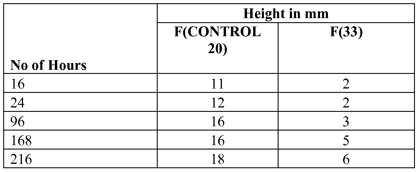
  • BDDBOl 5835935vl An oil wicking test was performed by suspending a piece of substrate in groundnut oil at a temperature of 160 0 C (320 0 F). The distance that the oil travelled up the web of substrate was measured. The unit of measurements used was millimeters (mm). [0232] The oil was replenished every 24 hours to avoid gelling.
  • Table 9 shows the height that the oil has wicked up the coated glasscloth piece as a function of time. It can be readily seen that the coating employing a HPTFE/LPTFE/PFA system, coating F(33) was considerably more resistant to oil ingress and wicking along the fabric fibers. It is believed that such improvement is due to a much more intimate contact between the coating and the glasscloth in the case of the F(33) coating versus the control F(20). Furthermore, it is also believed that this reduction in permeability is further facilitated by the essentially void free nature of the present coating systems, as discussed in the light transmission test of Example 6 above.
  • Adhesion tests were conducted under the following conditions: (1) the test was completed on a Lloyd LRX Tensometer; (2) Samples 25mm wide, 200mm in length are prepared by sealing 2 strips of fabric with PFA film (temperature 375°C, 25 seconds). [0236] The test is conducted at a speed of lOOmm/min for a distance of 25mm. An average reading of 3 measurements are quoted, and the units of measurement are lbs/f.
  • HPTFE/MPF/LPTFE topcoats were compared with their dispersion LPTFE equivalents.
  • the results are shown in Table 11 below. Examination of Table 11 reveals that the blends made using the micropowders TF9207 (topcoat F(44)) and UF8TA ( topcoat F(45)) as denoted by "HPTFE+HPTFE+HPTFE, PFA, MicroP" behave similarly to topcoats that include LPTFE obtained via emulsion polymerization and without being subjected to agglomeration, thermal degradation, or irradiation. The topcoats that include LPTFE micropowders were also observed to be generally superior to pure HPTFE-based topcoats.
  • HPTFE+HPTFE+HPTFE, PFA, MicroP topcoats do show inferior abrasion resistance when compared to the HPTFE/MPF/LPTFE topcoats, and hence might be considered intermediate in performance between pure HPTFE topcoats and HPTFE/MPF/LPTFE topcoats.
  • Equation 1 Normalized Surface Properties Calculation Mean ⁇ [Maximum (Ra) - (Ra)] /[Maximum (Ra) - Minimum (Ra)],
  • Equation 3 Normalized Abrasion Calculation
  • Figs. 1-18 are contour plots of the measured characteristics, including RAT and
  • TWI abrasion tests (Examples 3 and 4), cooking release tests (Example 5), and the roughness, contact angle and gloss tests (Example 2) plotted against PFA and LPTFE content for the topcoats in the Examples that include PFA.
  • Figs. 19-36 are contour plots of the measured characteristics, including RAT and
  • TWI abrasion tests (Examples 3 and 4), cooking release tests (Example 5), and the roughness, contact angle and gloss tests (Example 2) plotted against FEP and LPTFE content for the topcoats in the Examples that include FEP.
  • Figs. 37-54 are contour plots of the measured characteristics, including RAT and
  • TWI abrasion tests (Examples 3 and 4), cooking release tests (Example 5), and the roughness, contact angle and gloss tests (Example 2) plotted against MPF and LPTFE content for the topcoats in the Examples that include PFA, MFA and FEP (MPF).
  • MPF PFA, MFA and FEP
  • Figs. 15, 33, and 51 the results of the abrasion tests of Examples 3 and 4 are normalized.
  • Figs. 16, 34, and 52 the results of the cooking release tests of Example 5 are normalized.
  • Figs. 17, 35, and 53 the results of the surface property tests (Contact Angle Gloss and Roughness) of Example 2 are normalized.
  • Figs. 18, 36, and 54 the results of the abrasion tests of Examples 3 and 4, the cooking release tests of Example 5, and the roughness, contact angle and gloss tests of Example 2 are normalized.
  • Fig. 54 is the normalized plot of all of the data it is apparent that enhanced properties for the HPTFE, MPF, LPTFE topcoat can be obtained over a range of compositions and in particular with [LPTFE] ranging from 2-15 wt.% and [MPF] ranging from 2-30 wt.% or higher. Also a further region where [LPTFE] ranges from 15-90 wt.% or higher and [MPF] can range from 15-85 wt.% or higher shows enhanced properties compared to unblended HPTFE or LPTFE or MPF.
  • blends of these three types of polymers exhibit enhanced properties over a broad range of composition and optimum formulations will depend on the precise nature of the duty required of these blends.

Abstract

Blended fluoropolymer compositions that, in one exemplary application, may be applied as a coating to a flexible substrate and, optionally, to a flexible substrate that has been previously coated with a primer or basecoat and/or a midcoat. In one embodiment, the composition is a blend of at least one low molecular weight polytetrafluoroethyelene (LPTFE) and at least one melt-processible fluoropolymer (MPF). In another embodiment, the composition includes a fluoropolymer base component including at least one fluoropolymer such as high molecular weight polytetrafluoroethylene (HPTFE), and additionally includes the LPTFE/MPF blended fluoropolymer composition. After being applied to the flexible substrate, optionally over a primer or basecoat and/or midcoat, and then cured, the present compositions form coatings that demonstrate improved abrasion resistance and/or improved release characteristics and/or increased translucency/transparency and /or improved impermeability. The present compositions may also be used to produce films having a high degree of clarity and impermeability. The present compositions in powder form may be melt or paste extruded to form articles with improved impermeability.

Description

Leonard W. Harvey Helen L. Brain
BLENDED FLUOROPOLYMER COMPOSITIONS AND COATINGS FOR FLEXIBLE SUBSTRATES
Cross reference to related applications
[0001] This application also claims the benefit under Title 35, U.S.C. § 119(e) of U.S.
Provisional Patent Application Serial No. 61/100,311, entitled BLENDED FLUOROPOLYMER COMPOSITIONS, filed on September 26, 2008; U.S. Provisional Patent Application Serial No. 61/109,952, entitled BLENDED FLUOROPOLYMER TOPCOATS FOR FLEXIBLE SUBSTRATES, filed on October 31, 2008; U.S. Provisional Patent Application Serial No. 61/145,433, entitled BLENDED FLUOROPOLYMER COMPOSITIONS, filed on January 16, 2009; and U.S. Provisional Patent Application Serial No. 61/145,875, entitled BLENDED FLUOROPOLYMER COMPOSITIONS, filed on January 20, 2009, the disclosures of each are expressly incorporated by reference herein in their entirety.
BACKGROUND OF THE INVENTION [0001] 1. Field of the Invention.
[0002] The present invention relates to fluoropolymers and, in particular, relates to fluoropolymer compositions having improved properties, such as coatings of the type that are applied to flexible substrates, such as glasscloth, in which a non-stick surface and/or abrasion resistant surface is desired. In particular, the present invention relates to a fluoropolymer compositions that may be used to form coatings having improved non-stick or release characteristics and/or improved abrasion resistance, and to form films and blended powder compositions.
[0003] 2. Description of the Related Art.
[0004] Fluoropolymers are long-chain polymers comprising mainly ethylenic linear repeating units in which some or all of the hydrogen atoms are replaced with fluorine. Examples include polytetrafluoroethylene (PTFE), methylfluoroalkoxy (MFA), fluoro ethylene propylene (FEP), perfluoroalkoxy (PFA), poly(chlorotrifluoroethylene) and poly(vinylfluoride).
BDDBOl 5835935vl [0005] Glasscloth is one example of a flexible substrate that may be coated with a fluoropolymer coating. The coating typically includes a high molecular weight polytetrafluoroethylene (HPTFE), either by itself or including small amounts of additional polymers and/or fillers. One coating technique involves feeding a glasscloth web through a dip tank containing a dispersion of the fluoropolymer, and then feeding the coated web upwardly through a drying and sintering oven tower to cure or fix the coating. This process is usually repeated a number of times whereby up to 10 or more coating layers may be applied. [0006] What is needed is improved fluoropolymer compositions for applications such as coatings for flexible substrates, such as glasscloth, that demonstrate improved abrasion resistance and/or release characteristics, and for use in other applications.
SUMMARY OF THE INVENTION
[0007] The present invention provides blended fluoropolymer compositions that, in one exemplary application, may be applied as a coating to a flexible substrate and, optionally, to a flexible substrate that has been previously coated with a primer or basecoat and/or a midcoat. In one embodiment, the composition is a blend of at least one low molecular weight polytetrafluoroethyelene (LPTFE) and at least one melt-processible fluoropolymer (MPF). In another embodiment, the composition includes a fluoropolymer base component including at least one fluoropolymer such as high molecular weight polytetrafluoroethylene (HPTFE), and additionally includes the LPTFE/MPF blended fluoropolymer composition. After being applied to the flexible substrate, optionally over a primer or basecoat and/or midcoat, and then cured, the present compositions form coatings that demonstrate improved abrasion resistance and/or improved release characteristics and/or increased translucency/transparency and /or improved impermeability. The present compositions may also be used to produce films having a high degree of clarity and impermeability. The present compositions in powder form may be melt or paste extruded to form articles with improved impermeability.
[0008] In one form thereof, the present invention provides a fluoropolymer composition, comprising: at least one high molecular weight polytetrafluoroethylene (HPTFE) having a number average molecular weight (Mn) of at least 500,000 and present in an amount of between 1 wt. % and 98 wt.% based on the total solids weight of all fluoropolymers in the composition; at least one low molecular weight polytetrafluoroethylene (LPTFE) having a first melt
2
BDDBOl 5835935vl temperature (Tm) of 335° C or less and present in an amount of between 1 wt.% and 98 wt.% based on the total solids weight of all fluoropolymers in the composition; and at least one melt- processible fluoropolymer (MPF) present in an amount of between 1 wt.% and 98 wt.% based on the total solids weight of all fluoropolymers in the composition.
[0009] A coating applied to a substrate may include the fluoropolymer composition. A film may include the fluoropolymer composition. The fluoropolymer composition may be in the form of an aqueous dispersion or may be in the form of a powder. [0010] In another form thereof, the present invention provides a fluoropolymer composition, comprising: a fluoropolymer base component present in an amount of between 70 wt.% and 98 wt.% based on the total solids weight of all fluoropolymers in the composition, the fluoropolymer base component comprising at least one fluoropolymer including high molecular weight polytetrafluoroethylene (HPTFE) having a number average molecular weight (Mn) of at least 500,000; and a blended fluoropolymer composition present in an amount of between 2 wt.% and 30 wt.% based on the total solids weight of all fluoropolymers in the composition, the blended fluoropolymer composition comprising: at least one low molecular weight polytetrafluoroethylene (LPTFE) having a first melt temperature (Tm) of 335° C or less, and a mean particle size of 1.0 microns (μm) or less; and at least one melt-processible fluoropolymer (MPF).
[0011] In the composition, the at least one fluoropolymer base component may be present in an amount of between 75 wt.% and 96 wt.%, and the blended fluoropolymer composition may be present in an amount of between 4 wt.% and 25 wt.% based on the total solids weight of all fluoropolymers in the composition. In another embodiment, the at least one fluoropolymer base component may be present in an amount of between 82 wt.% and 96 wt.% and the blended fluoropolymer composition may be present in an amount of between 4 wt.% and 18 wt.% based on the total solids weight of all fluoropolymers in the composition. [0012] In the composition, the at least one melt-processible fluoropolymer may comprise perfluoroalkoxy (PFA) present in an amount between 37 wt.% and 65 wt.% based on the total solids weight of the fluoropolymers in the blended fluoropolymer composition. In another embodiment, the perfluoroalkoxy (PFA) may be present in an amount between 50 wt.% and 60 wt.% based on the total solids weight of the fluoropolymers in the blended fluoropolymer composition.
3
BDDBOl 5835935vl [0013] In the composition, the at least one melt-processible fluoropolymer may comprise fluorinated ethylene propylene (FEP) present in an amount between 20 wt.% and 85 wt.% based on the total solids weight of the fluoropolymers in the blended fluoropolymer composition. In another embodiment, the fluorinated ethylene propylene (FEP) may be present in an amount between 50 wt.% and 75 wt.% based on the total solids weight of the fluoropolymers in the blended fluoropolymer composition.
[0014] The at least one low molecular weight polytetrafluoroethylene (LPTFE) may have a mean particle size selected from the group consisting of 0.9 microns (μm) or less, 0.75 microns (μm) or less, 0.5 microns (μm) or less, 0.4 microns (μm) or less, 0.3 microns (μm) or less, and 0.2 microns (μm) or less, and/or may have a first melt temperature (Tm) selected from the group consisting of 332° C or less, 330° C or less, 329° C or less, 328° C or less, 327° C or less, 326° C or less, and 325° C or less.
[0015] The at least one low molecular weight polytetrafluoroethylene (LPTFE) may be obtained via emulsion polymerization without being subjected to agglomeration, thermal degradation, or irradiation, or may be an LPTFE micropowder obtained via emulsion polymerization or suspension polymerization with or without a subsequent molecular weight reduction step.
In another form thereof, the present invention provides a coated flexible substrate, comprising: a flexible substrate; a coating on said flexible substrate, comprising: at least one fluoropolymer including high molecular weight polytetrafluoroethylene (HPTFE) having a number average molecular weight (Mn) of at least 500,000 and present in an amount of between 70 wt.% and 98 wt.% based on the total solids weight of all fluoropolymers in the coating; at least one low molecular weight polytetrafluoroethylene (LPTFE) having a number average molecular weight (Mn) of less than 500,000 and present in an amount of between 1 wt.% and 30 wt.% based on the total weight of all fluoropolymers in the coating; and at least one melt- processible fluoropolymer present in an amount of between 1 wt.% and 30 wt.% based on the total weight of all fluoropolymers in the coating.
[0016] In the coating, the at least one low molecular weight polytetrafluoroethylene
(LPTFE) may be present in an amount of between 5 wt.% and 15 wt.%, and the at least one melt-processible fluoropolymer present in an amount of between 5 wt.% and 15 wt.%, based on the total weight of all fluoropolymers in the coating. The at least one melt-processible
4
BDDBOl 5835935vl fluoropolymer may comprise perfluoroalkoxy (PFA) present in an amount between 37 wt.% and 65 wt.% based on the combined total solids weight of the at least one low molecular weight polytetrafluoroethylene (LPTFE) and the at least one melt-processible fluoropolymer. [0017] The coating may have one or more properties selected from the group consisting of: a surface rougness (Ra) of less than 1.5 microns; and a measured gloss of at least 30% reflectance at 60°.
BRIEF DESCRIPTION OF THE DRAWINGS
[0018] The above-mentioned and other features and advantages of this invention, and the manner of attaining them, will become more apparent and the invention itself will be better understood by reference to the following description of an embodiment of the invention taken in conjunction with the accompanying drawings, wherein:
[0019] Fig. 1 shows a first contour plot of RAT ambient initial (Example 3) plotted against PFA and LPTFE content for the topcoats in the Examples that include PFA, together with a second plot of the HPTFE-rich area of the first plot;
[0020] Fig. 2 shows a first contour plot of RAT ambient 10% (Example 3) plotted against PFA and LPTFE content for the topcoats in the Examples that include PFA, together with a second plot of the HPTFE-rich area of the first plot;
[0021] Fig. 3 shows a first contour plot of TWI 1000 (Example 4) plotted against PFA and LPTFE content for the topcoats in the Examples that include PFA, together with a second plot of the HPTFE-rich area of the first plot;
[0022] Fig. 4 shows a first contour plot of TWI 2000 (Example 4) plotted against PFA and LPTFE content for the topcoats in the Examples that include PFA, together with a second plot of the HPTFE-rich area of the first plot;
[0023] Fig. 5 shows a first contour plot of TWI 3000 (Example 4) plotted against PFA and LPTFE content for the topcoats in the Examples that include PFA, together with a second plot of the HPTFE-rich area of the first plot;
[0024] Fig. 6 shows a first contour plot of cookie dough cooking release (Example 5) plotted against PFA and LPTFE content for the topcoats in the Examples that include PFA, together with a second plot of the HPTFE-rich area of the first plot;
BDDBOl 5835935vl [0025] Fig. 7 shows a first contour plot of pizza dough cooking release (Example 5) plotted against PFA and LPTFE content for the topcoats in the Examples that include PFA, together with a second plot of the HPTFE-rich area of the first plot;
[0026] Fig. 8 shows a first contour plot of chicken cooking release (Example 5) plotted against PFA and LPTFE content for the topcoats in the Examples that include PFA, together with a second plot of the HPTFE-rich area of the first plot;
[0027] Fig. 9 shows a first contour plot of roughness (Example 2) plotted against PFA and LPTFE content for the topcoats in the Examples that include PFA, together with a second plot of the HPTFE-rich area of the first plot;
[0028] Fig. 10 shows a first contour plot of gloss (Example 2) plotted against PFA and
LPTFE content for the topcoats in the Examples that include PFA, together with a second plot of the HPTFE-rich area of the first plot;
[0029] Fig. 11 shows a first contour plot of contact angle (Example 2) plotted against
PFA and LPTFE content for the topcoats in the Examples that include PFA, together with a second plot of the HPTFE-rich area of the first plot;
[0030] Fig. 12 shows a first contour plot of instantaneous force (Example 8) plotted against PFA and LPTFE content for the topcoats in the Examples that include PFA, together with a second plot of the HPTFE-rich area of the first plot;
[0031] Fig. 13 shows a first contour plot of kinetic force (Example 8) plotted against
PFA and LPTFE content for the topcoats in the Examples that include PFA, together with a second plot of the HPTFE-rich area of the first plot;
[0032] Fig. 14 shows a first contour plot of the normalized results of the adhesion tests
(Example 8) plotted against PFA and LPTFE content for the topcoats in the Examples that include PFA, together with a second plot of the HPTFE-rich area of the first plot;
[0033] Fig. 15 shows a first contour plot of the normalized results of the RAT and TWI abrasion tests (Examples 3 and 4) plotted against PFA and LPTFE content for the topcoats in the Examples that include PFA, together with a second plot of the HPTFE-rich area of the first plot;
[0034] Fig. 16 shows a first contour plot of the normalized results of the cooking release tests (Example 5) plotted against PFA and LPTFE content for the topcoats in the Examples that include PFA, together with a second plot of the HPTFE-rich area of the first plot;
6
BDDBOl 5835935vl [0035] Fig. 17 shows a first contour plot of the normalized results of the roughness, gloss, and contact angle tests (Example 2) plotted against PFA and LPTFE content for the topcoats in the Examples that include PFA, together with a second plot of the HPTFE-rich area of the first plot;
[0036] Fig. 18 shows a first contour plot of the normalized results of the RAT and TWI abrasion tests (Examples 3 and 4), the adhesion tests (Example 8), the cooking release tests
(Example 5), and the roughness, gloss, and contact angle tests (Example 2) plotted against PFA and LPTFE content for the topcoats in the Examples that include PFA, together with a second plot of the HPTFE-rich area of the first plot;
[0037] Fig. 19 shows a first contour plot of RAT ambient initial (Example 3) plotted against FEP and LPTFE content for the topcoats in the Examples that include FEP, together with a second plot of the HPTFE-rich area of the first plot;
[0038] Fig. 20 shows a first contour plot of RAT ambient 10% (Example 3) plotted against FEP and LPTFE content for the topcoats in the Examples that include FEP, together with a second plot of the HPTFE-rich area of the first plot;
[0039] Fig. 21 shows a first contour plot of TWI 1000 (Example 4) plotted against FEP and LPTFE content for the topcoats in the Examples that include FEP, together with a second plot of the HPTFE-rich area of the first plot;
[0040] Fig. 22 shows a first contour plot of TWI 2000 (Example 4) plotted against FEP and LPTFE content for the topcoats in the Examples that include FEP, together with a second plot of the HPTFE-rich area of the first plot;
[0041] Fig. 23 shows a first contour plot of TWI 3000 (Example 4) plotted against FEP and LPTFE content for the topcoats in the Examples that include FEP, together with a second plot of the HPTFE-rich area of the first plot;
[0042] Fig. 24 shows a first contour plot of cookie dough cooking release (Example 5) plotted against FEP and LPTFE content for the topcoats in the Examples that include FEP, together with a second plot of the HPTFE-rich area of the first plot;
[0043] Fig. 25 shows a first contour plot of pizza dough cooking release (Example 5) plotted against FEP and LPTFE content for the topcoats in the Examples that include FEP, together with a second plot of the HPTFE-rich area of the first plot;
BDDBOl 5835935vl [0044] Fig. 26 shows a first contour plot of chicken cooking release (Example 5) plotted against FEP and LPTFE content for the topcoats in the Examples that include FEP, together with a second plot of the HPTFE-rich area of the first plot;
[0045] Fig. 27 shows a first contour plot of roughness (Example 2) plotted against FEP and LPTFE content for the topcoats in the Examples that include FEP, together with a second plot of the HPTFE-rich area of the first plot;
[0046] Fig. 28 shows a first contour plot of gloss (Example 2) plotted against FEP and
LPTFE content for the topcoats in the Examples that include FEP, together with a second plot of the HPTFE-rich area of the first plot;
[0047] Fig. 29 shows a first contour plot of contact angle (Example 2) plotted against
FEP and LPTFE content for the topcoats in the Examples that include FEP, together with a second plot of the HPTFE-rich area of the first plot;
[0048] Fig. 30 shows a first contour plot of instantaneous force (Example 8) plotted against FEP and LPTFE content for the topcoats in the Examples that include FEP, together with a second plot of the HPTFE-rich area of the first plot;
[0049] Fig. 31 shows a first contour plot of kinetic force (Example 8) plotted against
FEP and LPTFE content for the topcoats in the Examples that include FEP, together with a second plot of the HPTFE-rich area of the first plot;
[0050] Fig. 32 shows a first contour plot of the normalized results of the adhesion tests
(Example 8) plotted against FEP and LPTFE content for the topcoats in the Examples that include FEP, together with a second plot of the HPTFE-rich area of the first plot;
[0051] Fig. 33 shows a first contour plot of the normalized results of the RAT and TWI abrasion tests (Examples 3 and 4) plotted against FEP and LPTFE content for the topcoats in the
Examples that include FEP, together with a second plot of the HPTFE-rich area of the first plot;
[0052] Fig. 34 shows a first contour plot of the normalized results of the cooking release tests (Example 5) plotted against FEP and LPTFE content for the topcoats in the Examples that include FEP, together with a second plot of the HPTFE-rich area of the first plot;
[0053] Fig. 35 shows a first contour plot of the normalized results of the roughness, gloss, and contact angle tests (Example 2) plotted against FEP and LPTFE content for the topcoats in the Examples that include FEP, together with a second plot of the HPTFE-rich area of the first plot;
BDDBOl 5835935vl [0054] Fig. 36 shows a first contour plot of the normalized results of the RAT and TWI abrasion tests (Examples 3 and 4), the adhesion tests (Example 8), the cooking release tests
(Example 5), and the roughness, gloss, and contact angle tests (Example 2) plotted against FEP and LPTFE content for the topcoats in the Examples that include FEP, together with a second plot of the HPTFE -rich area of the first plot;
[0055] Fig. 37 shows a first contour plot of RAT ambient initial (Example 3) plotted against MPF and LPTFE content for the topcoats in the Examples that include both PFA and
FEP (MPF), together with a second plot of the HPTFE-rich area of the first plot;
[0056] Fig. 38 shows a first contour plot of RAT ambient 10% (Example 3) plotted against MPF and LPTFE content for the topcoats in the Examples that include both PFA and
FEP (MPF), together with a second plot of the HPTFE-rich area of the first plot;
[0057] Fig. 39 shows a first contour plot of TWI 1000 (Example 4) plotted against MPF and LPTFE content for the topcoats in the Examples that include both PFA and FEP (MPF), together with a second plot of the HPTFE-rich area of the first plot;
[0058] Fig. 40 shows a first contour plot of TWI 2000 (Example 4) plotted against MPF and LPTFE content for the topcoats in the Examples that include both PFA and FEP (MPF), together with a second plot of the HPTFE-rich area of the first plot;
[0059] Fig. 41 shows a first contour plot of TWI 3000 (Example 4) plotted against MPF and LPTFE content for the topcoats in the Examples that include both PFA and FEP (MPF), together with a second plot of the HPTFE-rich area of the first plot;
[0060] Fig. 42 shows a first contour plot of cookie dough cooking release (Example 5) plotted against MPF and LPTFE content for the topcoats in the Examples that include both PFA and FEP (MPF), together with a second plot of the HPTFE-rich area of the first plot;
[0061] Fig. 43 shows a first contour plot of pizza dough cooking release (Example 5) plotted against MPF and LPTFE content for the topcoats in the Examples that include both PFA and FEP (MPF), together with a second plot of the HPTFE-rich area of the first plot;
[0062] Fig. 44 shows a first contour plot of chicken cooking release (Example 5) plotted against MPF and LPTFE content for the topcoats in the Examples that include both PFA and
FEP (MPF), together with a second plot of the HPTFE-rich area of the first plot;
BDDBOl 5835935vl [0063] Fig. 45 shows a first contour plot of roughness (Example 2) plotted against MPF and LPTFE content for the topcoats in the Examples that include both PFA and FEP (MPF), together with a second plot of the HPTFE-rich area of the first plot;
[0064] Fig. 46 shows a first contour plot of gloss (Example 2) plotted against MPF and
LPTFE content for the topcoats in the Examples that include both PFA and FEP (MPF), together with a second plot of the HPTFE-rich area of the first plot;
[0065] Fig. 47 shows a first contour plot of contact angle (Example 2) plotted against
MPF and LPTFE content for the topcoats in the Examples that include both PFA and FEP (MPF), together with a second plot of the HPTFE-rich area of the first plot; [0066] Fig. 48 shows a first contour plot of instantaneous force (Example 8) plotted against MPF and LPTFE content for the topcoats in the Examples that include both PFA and FEP (MPF), together with a second plot of the HPTFE-rich area of the first plot; [0067] Fig. 49 shows a first contour plot of kinetic force (Example 8) plotted against
MPF and LPTFE content for the topcoats in the Examples that include both PFA and FEP (MPF), together with a second plot of the HPTFE-rich area of the first plot; [0068] Fig. 50 shows a first contour plot of the normalized results of the adhesion tests
(Example 8) plotted against MPF and LPTFE content for the topcoats in the Examples that include both PFA and FEP (MPF), together with a second plot of the HPTFE-rich area of the first plot;
[0069] Fig. 51 shows a first contour plot of the normalized results of the RAT and TWI abrasion tests (Examples 3 and 4) plotted against MPF and LPTFE content for the topcoats in the Examples that include both PFA and FEP (MPF), together with a second plot of the HPTFE- rich area of the first plot;
[0070] Fig. 52 shows a first contour plot of the normalized results of the cooking release tests (Example 5) plotted against MPF and LPTFE content for the topcoats in the Examples that include both PFA and FEP (MPF), together with a second plot of the HPTFE-rich area of the first plot;
[0071] Fig. 53 shows a first contour plot of the normalized results of the roughness, gloss, and contact angle tests (Example 2) plotted against MPF and LPTFE content for the topcoats in the Examples that include both PFA and FEP (MPF), together with a second plot of the HPTFE-rich area of the first plot;
10
BDDBOl 5835935vl [0072] Fig. 54 shows a first contour plot of the normalized results of the RAT and TWI abrasion tests (Examples 3 and 4), the adhesion tests (Example 8), the cooking release tests
(Example 5), and the roughness, gloss, and contact angle tests (Example 2) plotted against MPF and LPTFE content for the topcoats in the Examples that include both PFA and FEP (MPF), together with a second plot of the HPTFE-rich area of the first plot;
[0073] Fig. 55 is a picture of the light source through sample F(33), a piece of glasscloth including a coating having HPTFE, PFA, and LPTFE (Example 6);
[0074] Fig. 56 is a picture of the light source through sample F(46) control, a piece of glasscloth including a coating having only HPTFE (Example 6); and
[0075] Fig. 57 is a picture of the naked light source used in Example 6.
[0076] The exemplifications set out herein illustrate embodiments of the invention, and such exemplifications are not to be construed as limiting the scope of the invention in any manner.
DETAILED DESCRIPTION
[0077] The present invention provides blended fluoropolymer compositions that, in one exemplary application, may be applied as a coating to a flexible substrate and, optionally, to a flexible substrate that has been previously coated with a primer or basecoat and/or a midcoat. In one embodiment, the composition is a blend of at least one low molecular weight polytetrafluoroethyelene (LPTFE) and at least one melt-processible fluoropolymer (MPF). In another embodiment, the composition includes a fluoropolymer base component including at least one fluoropolymer such as high molecular weight polytetrafluoroethylene (HPTFE), and additionally includes the LPTFE/MPF blended fluoropolymer composition. After being applied to the flexible substrate, optionally over a primer or basecoat and/or midcoat, and then cured, the present compositions form coatings that demonstrate improved abrasion resistance and/or improved release characteristics and/or increased translucency/transparency and /or improved impermeability. The present compositions may also be used to produce films having a high degree of clarity and impermeability. The present compositions in powder form may be melt or paste extruded to form articles with improved impermeability.
[0078] Suitable flexible substrates to which the present coating compositions may be applied include glasscloth of the type commonly used in applications such as food conveyer
11
BDDBOl 5835935vl belts for continuous ovens, architechtural fabrics of the type used in stadium roofs and radar domes, as well as heat sealing belts, circuit boards, cooking sheets, and tenting fabrics, for example. "Glasscloth" or "glass cloth" is a textile material made of woven fibers such as, for example, linen, glass, or cotton.
[0079] Other flexible substrates that may be coated with the present coating compositions include any material including natural or synthetic fibers or filaments, including staple fiber, fiberfill, yarn, thread, textiles, nonwoven fabric, wire cloth, ropes, belting, cordage, and webbing, for example. Exemplary fibrous materials which may be coated with the present coating compositions include natural fibers, such as vegetable, animal, and mineral fibers, including cotton, cotton denim, wool, silk, ceramic fibers, and metal fibers, as well as synthetic fibers, such as knit carbon fabrics, ultra high molecular weight polyethylene (UHMWPE) fibers, poly(ethylene terephthlalate) (PET) fibers, para-aramid fibers, including poly-paraphenylene terephtalamide or Kevlar®, and meta-aramid fibers, such as Nomex®, each available from E.I. du Pont de Nemours and Company, polyphenylene sulfide fibers, such as Ryton®, available from Chevron Phillips Chemical Co., polypropylene fibers, polyacrylic fibers, polyacrylonitrile (PAN) fibers, such as Zoltek®, available from Zoltek Corporation, polyamide fibers (nylon), and nylon-polyester fibers, such as Dacron®, available from Invista North America. [0080] The flexible substrate may optionally be coated with a primer (or basecoat) and/or a midcoat prior to application of the present coating compositions. The primer and midcoat may be any type of fluoropolymer-based coating, and commercially available coatings based on high molecular weight PTFE are widely available. The particular compositions of the primer and/or midcoat may vary widely, and are not thought to be critical with respect to the improved properties demonstrated by the coatings disclosed herein.
[0081] In particular, in one embodiment, the present coating composition is applied over an underlying coating, or undercoat. The undercoat may be a basecoat, which is the coating applied directly to an underlying substrate (sometimes referred to as a primer), optionally together with one or more midcoats. In these embodiments, the present coating may be referred to herein as either an "overcoat" or a "topcoat" and these terms are generally interchageable. In other embodiments, the present coating composition may be applied directly to a substrate to form a coating in direct contact with the substrate whereby the coating is not applied over any undercoats. In further embodiments, the present coating system may itself also be an undercoat.
12
BDDBOl 5835935vl [0082] In another application, free-standing films having high optical clarity and excellent impermeability may be cast from the present compositions. For example, films may be produced from the present compositions by casting the compositions onto a suitable surface from which they are removed after drying and curing.
[0083] In a still further application, powders having the compositions discussed herein may be prepared, which may then be dispersed in solution, or may extruded such as by paste or melt extrusion, for example, to produce articles with enhanced impermeability.
[0084] In a first embodiment described herein, the present composition generally includes a blended fluoropolymer composition of at least one low molecular weight PTFE
(LPTFE) and at least one melt processible fluoropolymer (MPF).
[0085] In a second embodiment described herein, the present composition generally includes at least one fluoropolymer base component and a blended fluoropolymer composition.
The fluoropolymer base component is typically a high molecular weight PTFE (HPTFE). The blended fluoropolymer composition includes at least one low molecular weight PTFE (LPTFE) and at least one melt processible fluoropolymer (MPF).
I. First Embodiment.
[0086] In a first embodiment, the composition is a blend of at least one low molecular weight PTFE (LPTFE) and at least one melt-processible fluoropolymer (MPF). Suitable fluoropolymer components and blends are discussed below, and are also discussed in U.S. Patent Application Serial No. 12/468,580, entitled "Blended Fluoropolymer Compositions", filed on May 19, 2009, assigned to the assignee of the present invention, the disclosure of which is expressly incorporated by reference herein.
A. Low molecular weight polvtetrafluoroethylene (LPTFE).
[0087] The first fluoropolymer of the present blended fluoropolymer composition may be a liquid dispersion of polytetrafluoroethylene (PTFE) and, in particular, may be a liquid dispersion of a PTFE having a low molecular weight (LPTFE) and/or optionally other properties as discussed in detail below.
[0088] The liquid dispersion of LPTFE in most embodiments will be an aqueous dispersion, though the LPTFE may be dispersed in other solvents and/or LPTFE originally in an
13
BDDBOl 5835935vl aqueous phase may be phase transferred into another solvent, such as organic solvents including hexane, acetone, or an alcohol.
[0089] The LPTFE, when produced as described above, will typically have a mean particle size of 1.0 microns (μm) or less, 0.9 microns (μm) or less, 0.75 microns (μm) or less,
0.5 microns (μm) or less, 0.4 microns (μm) or less, 0.3 microns (μm) or less, or 0.2 microns
(μm) or less, as measured by a suitable manner such as by laser light diffraction by ISO 13320.
In some embodiments, the LPTFE may have a mean particle size as low as 30, 50, 100, or 150 nm, or as large as 200, 250, or 350 nm, for example.
[0090] The number average molecular weight (Mn) of the LPTFE will typically be less than 500,000 and, in most embodiments, may be as low as 10,000 or greater, 20,000 or greater, or 25,000 or greater, or may be as high as 200,000 or less, 100,000 or less, or 70,000 or less,
60,000 or less, or 50,000 or less, for example.
[0091] An alternative manner of characterizing the molecular weight of the LPTFE is by its first melt temperature (Tm), as determined by a suitable method such as differential scanning calorimetry (DSC), which first melt temperature (Tm) for LPTFE may be either equal to or less than 335°C. In other embodiments, the first melt temperature of the LPTFE may be either equal to or less than 332°C, either equal to or less than 3300C, either equal to or less than 329°C, either equal to or less than 328°C, either equal to or less than 327°C, either equal to or less than
326°C, or either equal to or less than 325°C.
[0092] The LPTFE may be provided in the form of an aqueous dispersion which is stabilized, unstabilized, or minimally stabilized. As used herein, "unstabilized" or "minimally stabilized" refers to an aqueous dispersion that includes less than 1.0 wt.% of a traditional surfactant, such as non-ionic surfactant or an anionic surfactant, based on the weight of the
LPTFE aqueous dispersion. In some embodiments, the LPTFE dispersion may be provided in the form of an aqueous dispersion having less than 1.0 wt.% surfactant, less than 0.8 wt.% surfactant, less than 0.6 wt.% surfactant, or even less than 0.5 wt.% surfactant. In other embodiments, the LPTFE dispersion may be provided in the form of an aqueous dispersion that is "stabilized", typically having 1-12 wt.% surfactant. However, the nature of the stabilization package employed is not a critical feature of this invention.
[0093] Also, as discussed below, the LPTFE may be provided in the form of a solid micropowder.
14
BDDBOl 5835935vl [0094] The LPTFE will typically be in the form of a low molecular weight PTFE homopolymer. However, in other embodiments, the LPTFE may include a small amount of modifying co-monomer, in which case the PTFE is a co-polymer known in the art as "modified PTFE" or "trace modified PTFE". Examples of the modifying co-monomer include perfluoropropylvinylether (PPVE), other modifiers, such as hexafluoropropylene (HFP), chlorotrifluoroethylene (CTFE), perfluorobutylethylene (PFBE), or other perfluoroalkylvinylethers, such as perfluoromethylvinylether (PMVE) or perfluoroethylvinylether (PEVE). The modifying co-monomer will typically be present in an amount less than 1% by weight, for example, with respect to the PTFE.
[0095] Suitable LPTFE dispersions include SFN-D, available from Chenguang R.I. C. I,
Chengdu, 610036 P.R. China, as well as TE3877N, available from DuPont. Other exemplary LPTFE micropowders include Dyneon TF-9207, available from Dyneon LLC, LDW-410, available from Daikin Industries, Inc., and MP-25, MP-55, MP-8T and UF 8TA, each available from Laurel Products. [0096] These fluoropolymers have characteristics set forth in Table 1 below:
Table 1 Characteristics of exemplary low molecular weight polvtetrafluoroethylenes (LPTFE)
Figure imgf000016_0001
15
BDDBOl 5835935vl
Figure imgf000017_0001
[0097] Exemplary types of LPTFE that may be used in the present invention are discussed below. i. LPTFE produced by dispersion polymerization or emulsion polymerization and which is thereafter not agglomerated, irradiated, or thermally degraded. [0098] In some embodiments of the present invention, the LPTFE is produced by a polymerization process that is well known in the art as dispersion polymerization or emulsion polymerization. These polymerization processes may be conducted with chain transfer agents, which reduce the average molecular weight of the fluoropolymers produced, and/or via other methods whereby the polymerization process is controlled to form a liquid dispersion of directly polymerized particles of PTFE having low molecular weight (LPTFE). [0100] In these embodiments, the LPTFE, after being produced by dispersion polymerization or emulsion polymerization, is thereafter not agglomerated, irradiated, or thermally degraded. In particular, the LPTFE has not been subjected to any agglomeration steps during its manufacture, and therefore retains a small mean particle size. Further, the LPTFE has not been subjected to thermal degradation to reduce its molecular weight. Still further, the LPTFE has also not been subjected to irradiation, such as by high energy electron beam, to reduce its molecular weight. In these embodiments, the LPTFE dispersions will not demonstrate a spectrum and/or will be below a detection limit when subjected to electron paramagnetic resonance (EPR) or electron spin resonance (ESR) spectroscopy, as opposed to irradiated PTFE, which will demonstrate such a spectra and/or will otherwise have detectable free radicals. [0101] These types of LPTFE dispersions are provided as aqueous dispersions that are obtained via a controlled dispersion or emulsion polymerization process to produce directly polymerized LPTFE that is not thereafter subjected to agglomeration, thermal degradation, or irradiation. These types of LPTFE dispersions will be appreciated by those of ordinary skill in the art to be distinct from other PTFE materials that are commercially available.
16
BDDBOl 5835935vl [0102] First, these types of LPTFE dispersions are distinct from PTFE that is produced by the polymerization process well known in the art as granular or suspension polymerization, which yields PTFE known in the art as granular PTFE resin or granular PTFE molding powder. Granular PTFE resins will typically have a high molecular weight, such as a number average molecular weight (Mn) of at least 1,000,000 or more and a first melt temperature (Tm) greater than the 335°C, typically much greater than 335°C. Granular PTFE resin is typically provided in solid, powder form including particles having a mean particle size of several microns, typically from 10 to 700 microns (μm). These resins may also be provided as fine cut resins having a mean particle size of 20 to 40 microns (μm), for example.
[0103] Additionally, these types of LPTFE dispersions may be distinct from lower molecular weight materials prepared from high molecular weight granular PTFE resins that have been degraded by irradiation or thermal degradation to form low molecular weight materials known as granular PTFE micropowders, which typically have a particle size ranging between 0.2 and 20 microns (μm). Examples of granular PTFE micropowders include Zonyl® MP1200, MP1300, and MP1400 resins, available from DuPont (Zonyl® is a registered trademark of E.I. du Pont de Nemours & Co.).
[0104] Second, these types of LPTFE dispersions are also distinct from high molecular weight PTFE dispersions made from dispersion or emulsion polymerization conducted without chain transfer agents to thereby polymerize a high molecular weight PTFE having a number average molecular weight (Mn) of at least 1,000,000 or more, and a first melt temperature (Tm) greater than the 335°C, typically much greater than 335°C. These high molecular weight PTFE dispersions are typically stabilized with a traditional surfactant present in an amount greater than 1.0 wt.%, typically much greater than 1.0 wt.%.
[0105] Additionally, these types of LPTFE dispersions are also distinct from high molecular weight PTFE dispersions that are produced via dispersion or emulsion polymerization and thereafter coagulated or agglomerated.
[0106] Still further, these types of LPTFE dispersions are distinct from high molecular weight PTFE dispersions that are produced via dispersion or emulsion polymerization and thereafter coagulated or agglomerated, and then are subjected to thermal degradation or irradiation to form low molecular weight PTFE powders, known in the art as PTFE micropowders, which are provided as solid powders having a particle size between 0.2 and 20
17
BDDBOl 5835935vl microns (μm), such as for use in extrusion and other applications. Examples of PTFE micropowders include Zonyl® MPlOOO, MPl 100, MP 1500 and MP 1600 resins, available from DuPont (Zonyl® is a registered trademark of E.I. du Pont de Nemours & Co.). However, as discussed below, these types of LPTFE micropowders may also be used in the present invention. [0107] Third, these types of LPTFE dispersions are distinct from LPTFE micropowders that are polymerized via dispersion or emulsion polymerization in the presence of chain transfer agents, and then are agglomerated to form PTFE micropowders having an average particle size of between 0.2 and 20 microns (μm), for example. ii. LPTFE micropowders.
[0108] In a second embodiment of the present invention, the LPTFE may be in the form of an LPTFE micropowder.
[0109] A first type of LPTFE micropowders are derived from high molecular weight
PTFE dispersions that are produced via dispersion or emulsion polymerization and thereafter coagulated or agglomerated, and then subjected to thermal degradation or irradiation to form low molecular weight PTFE powders, known in the art as PTFE micropowders and referred to herein as LPTFE micropowders, which are typically provided as solid powders having a particle size typically between 0.2 and 20 microns (μm).
[0110] Examples of these types of LPTFE micropowders include Zonyl® MPlOOO,
MPl 100, MP 1500 and MP 1600 resins, available from DuPont (Zonyl® is a registered trademark of E.I. du Pont de Nemours & Co.); and MP-25, MP-55, and UF 8TA, each available from Laurel Products.
[0111] A second type of LPTFE micropowders are derived from high molecular weight granular PTFE resins that have been degraded by irradiation or thermal degradation to form low molecular weight materials known as granular PTFE micropowders, which typically have a particle size ranging typically between 2 and 20 microns (μm).
[0112] Examples of these types of LPTFE micropowders include Zonyl® MP1200,
MP1300, and MP1400 resins, available from DuPont (Zonyl® is a registered trademark of E.I. du Pont de Nemours & Co.) and MP-8T and MP-10, available from Laurel Products. [0113] A third type of these types LPTFE micropowders are polymerized via dispersion or emulsion or suspension polymerization in the presence of chain transfer agents, and then may
18
BDDBOl 5835935vl be agglomerated to form LPTFE micropowders having an average particle size of typically between 0.2 and 20 microns (μm), for example.
B. Melt processible fluoropolymers (MPF).
[0114] The second fluoropolymer of the blended fluoropolymer composition may be a liquid dispersion of one or more melt processible fluoropolymers (MPF), such as perfluoroalkoxy (PFA) (copolymers of tetrafluoroethylene (TFE) and perfluoroalkylvinyl ethers), including methylfluoroalkoxy (MFA) (a copolymer of tetrafluoroethylene (TFE) and perfluoromethylvinyl ether (PMVE)) and ethylfluoroalkoxy (EFA) (a copolymer of tetrafluoroethylene (TFE) and perfluoroethylvinyl ether (PEVE)); and fluorinated ethylene propylene (FEP), for example.
[0115] The MPF may be produced by a polymerization process that is well known in the art as dispersion polymerization or emulsion polymerization. These polymerization processes may be conducted with chain transfer agents, which reduce the average molecular weight of the fluoropolymers produced, and/or via other methods whereby the polymerization process is controlled to form a liquid dispersion of directly polymerized particles of MPF. [0116] In most embodiments, the MPF, after being produced by dispersion polymerization or emulsion polymerization, is thereafter not agglomerated, irradiated, or thermally degraded. In particular, the MPF will not have been subjected to any agglomeration steps during its manufacture, and therefore retains a small mean particle size as described below. [0117] The liquid dispersion of MPF in most embodiments will be an aqueous dispersion, though the MPF may be dispersed in other solvents and/or MPF originally in an aqueous phase may be phase transferred into another solvent, such as organic solvents including hexane, acetone, or an alcohol.
[0118] The MPF, when produced as described above, will typically have a mean particle size of 1.0 microns (μm) or less, 0.9 microns (μm) or less, 0.75 microns (μm) or less, 0.5 microns (μm) or less, 0.4 microns (μm) or less, 0.3 microns (μm) or less, or 0.2 microns (μm) or less. In particular, the MPF may have a mean particle size as low as 30, 50, 100, or 150 nm, or as large as 200, 250, or 350 nm, for example. [0119] In other embodiments, MPF powders could also be used.
19
BDDBOl 5835935vl [0120] The MPF may be provided in the form of an aqueous dispersion which is stabilized, unstabilized, or minimally stabilized. As used herein, "unstabilized" or "minimally stabilized" refers to an aqueous dispersion that includes less than 1.0 wt.% of a traditional surfactant, such as non-ionic surfactant or an anionic surfactant, based on the weight of the MPF aqueous dispersion. In some embodiments, the MPF dispersion may be provided in the form of an aqueous dispersion having less than 1.0 wt.% surfactant, less than 0.8 wt.% surfactant, less than 0.6 wt.% surfactant, or even less than 0.5 wt.% surfactant. In other embodiments, the MPF dispersion may be provided in the form of an aqueous dispersion that is "stabilized", typically having 1-12 wt.% surfactant.
[0121] Typically, the melt flow rate (MFR) of the MPF will be greater than 0.5 g/10 min and, in one embodiment, may be about 2 g/10 min or higher, as determined by ASTM D 1238. [0122] Also, the MPF will typically have a co-monomer content, i.e., a content of one or more monomers other than tetrafluoroethylene (TFE), of about 3.0 wt.% or greater, such as 4.0 wt.% or greater, 4.5 wt.% or greater, 5.0 wt.% or greater, 5.5 wt.% or greater, or 6.0 wt.% or greater.
[0123] Suitable MPF dispersions include TE7224 (PFA), available from DuPont, 6900Z
(PFA), available from Dyneon LLC, TE9568 (FEP), available from DuPont, Neofion ND-110 (FEP), available from Daikin, and Hyfion XPH 6202-1 (MFA), available from Solvay. These MPF dispersions have characteristics set forth in Table 2 below:
Table 2 Characteristics of exemplary melt processible fluoropolvmers (MPF)
Figure imgf000021_0001
20
BDDBOl 5835935vl I (MFA)
C. LPTFE/MPF blend compositions.
[0124] To form the blended fluoropolymer composition compositions of the present invention, a LPTFE liquid dispersion and a MPF liquid dispersion are blended together. When liquid dispersions are used, the dispersions may have varying solids contents, and one of ordinary skill in the art will recognize that the wet weights of the liquid LPTFE and MPF dispersions may be selected based on the solids contents of the dispersions and the desired relative weight percent ratio of the LPTFE and MPF that is desired in the resulting blended compositions.
[0125] Notably, when the LPTFE and the MPF are provided in the form of liquid dispersions having the small mean particle sizes set forth above, upon blending of the dispersions particles of the LPTFE and MPF are brought into contact with each other at the submicron level, prior to later processing steps in which the dispersions are dried or melted, for example. As discussed above, the LPTFE and MPF are, in one embodiment, not agglomerated prior to blending, such that the submicron interaction of the LPTFE and MPF is thought to facilitate the formation of a specific crystalline form of the dried or cured fluoropolymer blend that is believed to be important to achieving the beneficial results obtained with the present blended compositions. Although blending of the components in the liquid state is desirable in many applications, for other applications, powder blends are also desirable, as demonstrated in the present Examples by the effectiveness of micropowders when employed as the LPTFE component.
[0126] The relative ratios, fractions, or weight percents of the LPTFE and MPF in the blended fluoropolymer compositions described below are based on the total solids weight of the LPTFE and MPF fluoropolymers, excluding other fluoropolymers other than LPTFE and MPF as well as non-fluoropolymer components that may be present, such as water or other solvents, surfactants, pigments, fillers, and other compositions.
[0127] The LPTFE may comprise as little as 5 wt.%, 10 wt.%, or 15 wt.%, or as much as
85 wt.%, 90 wt.%, or 95 wt.% by weight of the blended fluoropolymer composition. In one embodiment, the LPTFE may comprise between 40 wt.% and 60 wt.% of the blended composition, such as 50 wt.% of the blended fluoropolymer composition. The MPF may comprise as much as 85 wt.%, 90 wt.%, or 95 wt.%, or as little as 5 wt.%, 10 wt.%, or 15 wt.%
21
BDDBOl 5835935vl by weight of the blended fluoropolymer composition. In one embodiment, the MPF may comprise between 40 wt.% and 60 wt.% of the blended fluoropolymer composition, such as 50 wt. % of the blended composition.
[0128] Blends of LPTFE and MFA may include, in one embodiment, from 35 wt.% to 90 wt.% MFA and from 10 wt.% to 65 wt.% LPTFE. In another embodiment, such blends may include from 35 wt.% to 76 wt.% MFA and from 24 wt.% to 65 wt.% LPTFE. In another embodiment, such blends may include from 56 wt.% to 76 wt.% MFA and from 24 wt.% to 44 wt.% LPTFE. In another embodiment, such blends may include from 63 wt.% to 70 wt.% MFA and from 30 wt.% to 37 wt.% LPTFE. In a further embodiment, such blends may include 67 wt.% MFA and 33 wt.% LPTFE.
[0129] Blends of LPTFE and FEP may include, in one embodiment, from 25 wt.% to 90 wt.% FEP and from 10 wt.% to 75 wt.% LPTFE. In another embodiment, such blends may include from 35 wt.% to 90 wt.% FEP and from 10 wt.% to 65 wt.% LPTFE. In another embodiment, such blends may include either from 35 wt.% to 55 wt.% FEP and from 45 wt.% to 65 wt.% LPTFE, or from 60 wt.% to 90 wt.% FEP and from 10 wt.% to 40 wt.% LPTFE. In another embodiment, such blends may include either from 40 wt.% to 50 wt.% FEP and from 50 wt.% to 60 wt.% LPTFE, or from 75 wt.% to 85 wt.% FEP and from 15 wt.% to 25 wt.% LPTFE. In a further embodiment, such blends may include either 50 wt.% FEP and 50 wt.% LPTFE, or 75 wt.% FEP and 25 wt.% LPTFE.
[0130] Blends of LPTFE and PFA may include, in one embodiment, from 37 wt.% to 80 wt.% PFA and from 20 wt.% to 63 wt.% LPTFE. In another embodiment, such blends may include from 37 wt.% to 65 wt.% PFA and from 35 wt.% to 63 wt.% LPTFE. In another embodiment, such blends may include from 43 wt.% to 63 wt.% PFA and from 37 wt.% to 57 wt.% LPTFE. In another embodiment, such blends may include from 50 wt.% to 60 wt.% PFA and from 40 wt.% to 50 wt.% LPTFE. In a further embodiment, such blends may include 53 wt.% PFA and 47 wt.% LPTFE.
[0131] When aqueous dispersions are used, the dispersions may have varying solids contents. The wet weights of the aqueous dispersions of the first and second fluoropolymers to be blended are selected based on the solids contents of the dispersions and the desired relative weight percents of the fluoropolymers. Powders of the fluoropolymers may also be blended and then, if desired, dispersed.
22
BDDBOl 5835935vl [0132] The coating compositions described herein may also include suitable additives, such as surfactants, fillers, reinforcement additives, and pigments, if desired. [0133] The coating compositions can be prepared by any standard formulation technique such as simple addition and low shear mixing. The coating compositions may be applied over a primer and/or midcoat by any known technique, and are then cured to provide a coated flexible substrate with a coating having improvements in abrasion resistance and release characteristics. The particular compositions of the primer and/or midcoat may vary widely, and are not thought to be critical with respect to the improved properties demonstrated by the coatings disclosed herein. However, as has been observed in connection with Example 7 below, improved resistance to oil and grease ingress may be obtained when no primer or midcoat is used under the present coating.
[0134] The coatings may be applied to a dry film thickness (DFT) of between 15 and 80 microns, depending on the application, and may be cured at a temperature above about 4000C for between 2 and 10 minutes, depending on the applied thickness. Depending on the application and degree of thickness desired, the coatings may be applied in several layers.
II. Second Embodiment.
[0135] In a second embodiment, the composition includes a fluoropolymer base component, such as a high molecular weight polytetrafluoroethylene (HPTFE), together with an amount of the above-described LPTFE/MPF blended fluoropolymer composition.
A. Fluoropolvmer base component.
[0136] The fluoropolymer base component includes at least one fluoropolymer, such as polytetrafluoroethylene (PTFE), co-polymers of tetrafluoroethlyene and ethylene (ETFE), copolymers of tetrafluoroethlyene and perfluoro(alkyl vinyl ethers) (PAVE), co-polymers of tetrafluoroethlyene and perfluoro(ethyl vinyl ether) (PEVE), co-polymers of tetrafluoroethylene and perfluoro(propyl vinyl ether) (PPVE), co-polymers of tetrafluoroethlyene and perfluoro(methyl vinyl ether) (PMVE), co-polymers of tetrafluoroethylene and hexafluoropropylene (FEP), co-polymers of tetrafluoroethylene and perfluoroalkoxy (PFA) and polyvinylidene fluoride (PVDF), and co-polymers of tetrafluoroethylene, hexafluoropropylene,
23
BDDBOl 5835935vl and vinylidene difluoride (THV), and other perfluorinated polymers. Fluoroelastomers based on PTFE may also be used.
[0137] Typically, the fluoropolymer base component will be one or more perfluorinated fluoropolymers and, in particular, will be one or more traditional high molecular weight PTFE (HPTFE) components.
[0138] The number average molecular weight (Mn) of the HPTFE is typically at least
500,000, and may be at least 1,000,000, and suitable HPTFE in the form of liquid dispersions and/or powders are available from many commercial sources. Liquid HPTFE dispersions typically include surfactants for stability, though "unstabilized" HPTFE dispersions, typically having less than 1.0 wt.% surfactant, are also available and may also be used. When a powder is used, the powder will typically be dispersed in a liquid to prepare the coating composition. [0139] In some embodiments, the HPTFE may include a small amount of modifying co- monomer, in which case the HPTFE is a co-polymer known in the art as "modified PTFE" or "trace modified PTFE". Examples of the modifying co-monomer include perfluoropropylvinylether (PPVE), other modifiers, such as hexafluoropropylene (HFP), chlorotrifluoroethylene (CTFE), perfluorobutylethylene (PFBE), or other perfluoroalkylvinylethers, such as perfluoromethylvinylether (PMVE) or perfluoroethylvinylether (PEVE). The modifying co-monomer will typically be present in an amount less than 1% by weight, for example, based on the weight of the HPTFE.
B. LPTFE/MPF blend compositions.
[0140] The LPTFE/MPF blend compositions are those describe above with respect to the first embodiment.
C. HPTFE/LPTFE/MPF blend compositions.
[0141] To form the present composition, aqueous dispersions of the components of the present coating composition may be blended in any order with slow stirring, for example, or via another low or medium shear method which minimizes the potential for agglomeration, coaglulation, or fibrillation of the fluoropolymer particles. When liquid dispersions are used, the dispersions may have varying solids contents, and one of ordinary skill in the art will recognize that the wet weights of the liquid HPTFE, LPTFE and MPF dispersions may be selected based
24
BDDBOl 5835935vl on the solids contents of the dispersions and the desired relative weight percent ratios of the HPTFE, LPTFE and MPF that are desired in the resulting blended compositions. [0142] In one embodiment, based on the solids content of all fluoropolymer components of the present compositions, the fluoropolymer base component is present in an amount of as little as 1 wt.%, 2 wt.% 4 wt.%, 10 wt.%, 30 wt.%, 35 wt.%, 40 wt.%, 45 wt.%, 55 wt.%, 60 wt.%, or 70 wt.%, or as great as 80 wt.%, 90 wt.%, 95 wt.%, 96 wt.%, or 98 wt.%, or within a range defined between any pair of the foregoing values, with each or both of the components of the blended fluoropolymer composition present in an amount of as little as 1 wt.%, 2 wt.%, 4 wt.%, 5 wt.%, 10 wt.%, or 20 wt.%, or as great as 30 wt.%, 40 wt.%, 45 wt.%, 55 wt.%, 60 wt.%, 65 wt.%, 70 wt.%, 96 wt.%, 98 wt.%, or 99 wt.%, or within a range defined between any pair of the foregoing values.
[0143] In particular embodiments, the fluoropolymer base component may be present in the composition in an amount of between 60 and 98 wt.%, between 70 and 98 wt.%, or between 82 and 96 wt.%, for example, based on the total weight of all fluoropolymers in the composition. The LPTFE/MPF blended fluoropolymer may be present in a corresponding amount of between 2 and 40 wt.%, between 2 and 30 wt.%, or between 4 and 18 wt.%, for example, based on the total weight of all fluoropolymers in the composition.
[0144] With respect to the amounts of LPTFE and MPF relative to one another, in particular embodiments, the LPTFE may be present in an amount of between 33 wt.% and 66 wt.%, between 40 wt.% and 60 wt.%, between 45 wt.% and 55 wt.%, or present in an amount of 50 wt.%, based on the combined solids content of the LPTFE and MPF components, with the MPF present in a corresponding amount of between 33 wt.% and 66 wt.%, between 40 wt.% and 60 wt.%, between 45 wt.% and 55 wt.%, or present in an amount of 50 wt.%, based on the combined solids content of the LPTFE and MPF components. In other words, the LPTFE/MPF ratio may be between 2:1 and 1 :2, between 1.5:1 and 1 : 1.5, between 1.2: 1 and 1 : 1.2, or may be 1 : 1 based on the combined solids content of the LPTFE and MPF components. [0145] When aqueous dispersions are used, the dispersions may have varying solids contents. The wet weights of the aqueous dispersions of the first and second fluoropolymers to be blended are selected based on the solids contents of the dispersions and the desired relative weight percents of the fluoropolymers. Powders of the fluoropolymers may also be blended and then dispersed.
25
BDDBOl 5835935vl [0146] The compositions described herein may also include suitable additives, such as surfactants, fillers, reinforcement additives, and pigments, if desired.
[0147] The compositions can be prepared by any standard formulation technique such as simple addition and low shear mixing. The compositions may be applied over a primer and/or midcoat or may be overcoated by any known technique, and are then cured to provide a coated flexible substrate with a coating having improvements in abrasion resistance and release characteristics. The particular compositions of the primer and/or midcoat may vary widely, and are not thought to be critical with respect to the improved properties demonstrated by the coatings disclosed herein. However, as has been observed in connection with Example 7 below, improved resistance to oil and grease ingress may be obtained when no primer or midcoat is used under the present coating.
[0148] The compositions may be applied to a dry film thickness (DFT) of between 15 and 80 microns, depending on the application, and may be cured at a temperature above about 4000C for between 2 and 10 minutes, depending on the applied thickness. Depending on the application and degree of thickness desired, the compositions may be applied in several layers. [0149] It has been found that blending of the dispersions facilitates interaction of the
LPTFE and MPF, and of the HPTFE, LPTFE and MPF, on a submicron level to facilitate intimate blending such that, when the blended fluoropolymer composition is dried, a crystal structure representing a true alloy of the fluoropolymers is formed, having melt characteristics that differ from those of the individual fluoropolymers. The blended fluoropolymer composition may be used to provide a coating having improved abrasion resistance, gloss, adhesion, and higher contact angles.
III. Physical properties.
[0150] Coatings and films prepared from the compositions of the first and second embodiments described above may exhibit one or more of the following properties, together with additional properties, as evidenced by the following Examples.
[0151] The present composition, when applied to a flexible substrate, either directly to the flexible substrate or over an underlying coating, or formed into a film, exhibits a contact angle of at least 100°, and may have a contact angle of at least 110°, 120°, 125°, 130°, or 135°, for example, as measured for a water droplet according to the Young Relation. Contact angle
26
BDDBOl 5835935vl may be measured according to ASTM D7334-08 with any suitable commercially available instrument, such as the "Drop Shape Analysis" system (DSAlO), available from Kruss GmbH of Hamburg, Germany.
[0152] The present composition, when applied to a substrate, either directly to the substrate or over an underlying coating, or formed into a film, exhibits a surface roughness (Ra, arithmetic mean deviation of the roughness profile, measured in microns) of less than 1.5 microns, and may have a surface roughness of less than 1.3 microns, 1.2 microns, or 1.0 microns, for example, as determined according to EN ISO 13565 in Example 2 below. [0153] The present composition, when applied to a flexible substrate, either directly to the flexible substrate or over an underlying coating, or formed into a film, exhibits a measured gloss, in % reflectance, of at least 15, and may have a measured gloss of at least 25, 30, 35, 40, or 45, for example, as measured at 60° with any suitable commercially available instrument, such as a Microgloss 60° glossmeter, available from Byk-Gardner, in accordance with the following standards: BS3900/D5, DIN EN ISO 2813, DIN 67530, EN ISO 7668, ASTM D523, ASTM D1455, ASTM C346, ASTM C584, ASTM D2457, JIS Z 8741, MFT 30064, TAPPI T 480. Units of measurement are expressed as % reflectance.
[0154] The present composition, when applied to a flexible substrate, either directly to the flexible substrate or over an underlying coating, or formed into a film, exhibits a light transmission, obtained in accordance with Example 6 below, of at least 60%, and may have a measured light transmission of at least 70%, at least 75%, or at least 80%, for example. [0155] The present composition, when applied to a flexible substrate, either directly to the flexible substrate or over an underlying coating, exhibits adhesion, as obtained in accordance with Example 8 below, of at least 4 lb/f, at least 5 lb/f, at least 6 lb/f, or at least 7 lb/f instantaneous force, and/or at least 4 lb/f, at least 5 lb/f, at least 6 lb/f, or at least 7 lb/f kinetic force, as measured by the peel test described in Example 8 below.
EXAMPLES
[0156] The following non- limiting Examples illustrate various features and characteristics of the present invention, which is not to be construed as limited thereto. Throughout the Examples and elsewhere herein, percentages are by weight unless otherwise indicated.
27
BDDBOl 5835935vl Example 1
Exemplary compositions and application to a flexible substrate, ι.g., glasscloth
[0157] In this Example, coatings were made from compositions of blended fluoropolymers in accordance with the first embodiment of present invention, and from high molecular weight PTFE (HPTFE) together with blended fluoropolymers in accordance with the second embodiment of present invention.
[0158] In this Example, these compositions were coated onto glasscloth over basecoats and/or midcoats, and the resulting coating systems were tested for abrasion resistance, release properties, and other properties in the remaining Examples.
[0159] The formulations of the basecoat and midcoats are set forth in Tables 3A and 3B, respectively, and are expressed as wet weight fractions whereas the topcoat components, set forth in Table 3C, are expressed as dry weight fractions.
Table 3A Basecoat formulations
Figure imgf000029_0001
28
BDDBOl 5835935vl
Figure imgf000030_0001
29
BDDBOl 5835935vl
Figure imgf000031_0001
Table 3B Midcoat formulations
Figure imgf000031_0002
30
BDDBOl 5835935vl
Figure imgf000032_0001
31
BDDBOl 5835935vl
Figure imgf000033_0001
32
BDDBOl 5835935vl
Figure imgf000034_0001
Table 3C Topcoat formulations
Figure imgf000034_0002
33
BDDBOl 5835935vl
Figure imgf000035_0001
34
BDDBOl 5835935vl
Figure imgf000036_0001
[0160] The fluoropolymer components of the Topcoats were as follows:
[0161] PTFE (HPTFE) - Solvay D3112X, solids = 60%.
[0162] MFA - Solvay Hyflon MFA XPH 6202-1, Lot# Lab, solids = 27.2%.
[0163] PFA - du Pont PFA TE7224, Lot# 0804330005, Solids = 58.6%).
[0164] FEP - du Pont FEP TE9568, solids = 54.0%).
[0165] LPTFE - SFN-D, Chenguang, except that topcoat F(44) was made with Dyneon
9207 TF PTFE micropowder, and topcoat F(45) was made with UF 8TA surface treated PTFE micropowder.
35
BDDBOl 5835935vl [0166] THV - Dyneon THV 340C, solids = 50.0%, used with Versamid cross-linking agent.
[0167] PAI-PPS - PAI: Whitford D7949 PAI solution, PPS: Chevron Phillips
Ryton PPS.
[0168] All of the coating compositions were mixed using a standard mixer under medium shear for 5-7 minutes. All mixed coatings were applied to glasscloth in the laboratory using draw down bars. The glasscloth substrate grades are set forth in Table 3A above, produced by
PD Interglas or Porcher Industries. The coated substrate is subjected to a flash off in a laboratory box oven set at 2600C (5000F) for 2 minutes followed by curing in a laboratory box oven set at
4000C (752°F) for 1 minute.
[0169] The control samples were standard products produced using conventional PTFE dispersions by AFC (Advanced Flexible Composites) and no modifications or further coatings were applied to these samples. The basecoat, midcoat and PTFE of the topcoat of the control samples were all standard PTFE dispersions.
[0170] Due to line speed conditions used in some trials dwell time at temperature was reduced. In these instances samples were post cured in a laboratory box oven for 2 minutes at
4300C. Substrate temperature was measured and 4300C was attained for between 45 and 52 seconds. Samples were subjected to a full test schedule to determine whether dwell time had any effect on properties. The foregoing samples are labeled "recure" or "recured" in the tables herein.
Example 2 Determination of roughness, gloss, and contact angle
[0171] In this Example, roughness, gloss, and contact angle of the coatings were determined. The test protocols are as follows.
[0172] Roughness. A stylus type surface roughness detector equipped with an analyzer that provides a tracing of the surface was used according to EN ISO 13565, such as the following: Mitutoyo Surftest 402 surface roughness detector and analyzer, available from Mitutoyo Canada, 2121 Meadowvale Blvd, Mississauga, Toronto, Ontaria, ON L5N 5Nl, and Perthometer M2P / M3P / M4P surface roughness detector and analyzer (Mahr GmbH
36
BDDBOl 5835935vl - Carl-Mahr-Str.1 , D-37073 Gόttingen, Germany). These instruments measure Ra (arithmetic mean deviation of the roughness profile, measured in microns) and Pc (peak count).
[0173] The procedure is as follows. First, prepare the sample to be measured. Due to the configuration of most detectors this may require cutting the sample to obtain a flat surface accessible to the detector. Set the detector roughness range to the level just higher than the expected roughness to be measured. Set the length of trace, scale magnification and measurement units (English or metric). Calibrate the detector according to the manufacturer's instructions using a known reference standard. In the same manner, measure the roughness of the sample surface. Make at least 6 measurements.
[0174] Gloss. Gloss measurements were attained using a Miniglossmeter 110V 20°-60°, available from Sheen Instruments, at an angle of 60°. The gloss meter conformed to the following standards: BS3900/D5, DIN EN ISO 2813, DIN 67530, EN ISO 7668, ASTM D523,
ASTM D1455, ASTM C346, ASTM C584, ASTM D2457, JIS Z 8741, MFT 30064, TAPPI T
480. Units of measurement are expressed as % reflectance.
[0175] Contact Angle. Contact angle was measured for a water droplet and is expressed in degrees, as determined according to ASTM D7334-08 using the "Drop Shape Analysis" system (DSAlO), available from Kruss GmbH of Hamburg, Germany, according to the Young
Relation.
[0176] The results are set forth in Table 4 below:
Table 4 Roughness, Gloss and Contact Angle
Figure imgf000038_0001
37
BDDBOl 5835935vl
Figure imgf000039_0001
38
BDDBOl 5835935vl
Figure imgf000040_0001
[0177] The results in Table 4 above show a significant improvement in smoothness, an increase in gloss, and an increase in the contact angle of water over the control topcoats for coating compositions made in accordance with the first and second embodiments of the present invention when applied to flexible glass substrates.
Example 3 Reciprocating abrasion test
[0178] A reciprocating abrasion test (RAT) was conducted on each coating under the test protocol set forth at the end of this Example. The results are set forth in Table 5 below:
Table 5 Reciprocating abrasion test (RAT)
39
BDDBOl 5835935vl
Figure imgf000041_0001
40
BDDBOl 5835935vl
Figure imgf000042_0001
[0179] The results in the table above show that there is up to a 200% improvement in linear abrasion resistance over the control topcoats with the topcoats made in accordance with the first and second embodiments of the present when applied to flexible glass substrates.
41
BDDBOl 5835935vl Reciprocating abrasion rest (RAT).
[0180] The reciprocating abrasion test was conducted based on the complete protocol set forth below with the following modifications: (1) the coated sample were tested until 10% exposure of substrate; (2) the test was performed using a 3kg weight at ambient temperature; and (3) the Scotchbrite 3M (7447) pads were changed every 1000 cycles. [0181] The complete test protocol is as follows:
[0182] Scope. This test measures the resistance of coatings to abrasion by a reciprocating Scotch-Brite pad. The test subjects coating abrasion in a back and forth motion. The test is a measure of the useful life of coatings that have been subjected to scouring and other similar forms of damage caused by cleaning. TM 135C is specific to a test apparatus built by Whitford Corporation of West Chester, PA. However, it is applicable to similar test methods such as the one described in British Standard 7069-1988. [0183] Equipment and Materials.
[0184] (1) A test machine capable of holding a Scotch-Brite abrasive pad of a specific size to the surface to be tested with a fixed force and capable of moving the pad in a back and forth (reciprocating) motion over a distance to 10 - 15 cm (4 to 6 inches). The force and motion are applied by a free falling, weighted stylus. The machine must be equipped with a counter, preferably one that may be set to shut off after a given number of cycles.
[0185] (2) Scotch-Brite pads of required abrasiveness cut to required size. Scotch-Brite pads are made by 3M Company, Abrasive Systems Division, St Paul, MN 55144-1000. Pads come in grades with varying levels of abrasiveness as follows:
Lowest -7445, 7448, 6448, 7447. 6444, 7446, 7440, 5440 - Highest
[0186] Scotch-Brite pads may be used at temperatures up to 1500C (3000F). Equivalent pads may be used.
[0187] (3) Hot plate to heat test specimens. (Optional)
[0188] (4) Detergent solution or oil for performing test in with a liquid. (Optional)
[0189] Procedure.
42
BDDBOl 5835935vl [0190] Before beginning the test, the end point must be defined. Usually, the end point is defined when some amount of substrate has been exposed. However, the end point may be defined as a given number of strokes even if substrate is not exposed. The present inventors use a 10% exposure of substrate over the abraded area as the standard definition of end point. Other end points may be used.
[0191] Secure the part to be tested under the reciprocating pad. The part must be firmly fastened with bolts, clamps or tape. The part should be as flat as possible and long enough so that the pad does not run off an edge. Bumps in the surface will wear first, and overrunning an edge can tear the pad and cause premature scratching and a false result.
[0192] Cut a piece of Scotch Brite of required abrasiveness to the exact size of the "foot" of the stylus. The present inventors use Grade 7447 as standard, and the "foot" of the stylus on the test machine is 5 cm (2 inches) in diameter. Attach the pad to the bottom of the "foot." The
Scotch-Brite pad is fixed to the "foot" by means of a piece of "Velcro" glued to the bottom of the foot.
[0193] If the machine has an adjustable stroke length, set the required length. The present inventors use a 10 cm (4 inch) stroke length as standard. Lower the pad onto the surface of the piece to be tested. Make sure that the weight is completely free. The present inventors used a 3.0 Kg weight as standard, but this can be varied.
[0194] If the machine is equipped with a counter, set the counter to the required number of strokes. One stroke is a motion in one direction. If the machine does not have an automatic counter, the counter must be watched so that the machine can be turned off at the proper time.
The machine is stopped at various intervals to change the abrasive pad. The abrasiveness of the pad changes (usually becomes less effective) as the pad fills with debris. The present inventors changed pads at intervals of 1,000 strokes. One thousand strokes is the preferred interval between pad changes.
[0195] Start the test machine. Allow to run until an end point is reached or until a required number of strokes are attained before changing the pad.
[0196] Inspect the test piece carefully at the beginning and end of each start up. As the end point is approached, the substrate will begin to show through the coating. When close to the end point, observe the test piece constantly. Stop the machine when the end point has been reached.
43
BDDBOl 5835935vl [0197] Evaluation.
[0198] Record the following for the test machine:
[0199] 1. Grade and size of Scotch-Brite pad.
[0200] 2. Load on stylus
[0201 ] 3. Number of strokes between pad changes .
[0202] 4. Length of stroke.
[0203] 5. Definition of end point.
[0204] 6. Number of strokes to end point.
[0205] Duplicate tests provide greater reliability. Indicate if end point is a single result or the average of several results.
[0206] Record the description of the coating, the film thickness, and the substrate and surface preparation.
[0207] If the test is conducted to a specific number of strokes, record the number of strokes. Record a description of the amount of wear, such as percent of substrate exposed, or number of strokes to first substrate exposure. Optionally, record the film thickness and/or weight before and after testing.
[0208] If the test is performed at elevated temperature, record the temperature of the test.
If performed with a liquid, record the specifics of the liquid.
[0209] Comments/Precautions.
[0210] Both sides of a Scotch-Brite pad may be used. Pads must be cut precisely to fit the "foot." Ragged edges or rough spots on the pad will give false results. Test pieces must be flat and free from dirt or other particles. This test method is similar to the abrasion test described in BS 7069: 1988, Appendix Al . When tested according to BS 7069, test pieces are immersed in
50 cm3 of a 5 g/liter solution of household dish washing detergent in water. The test runs for 250 cycles with pads changed every 50 cycles.
Example 4 Taber reciprocating abrasion test
44
BDDBOl 5835935vl [0211] A Taber reciprocating abrasion test was conducted according to ASTM D3389 under the following conditions: (1) the test was completed on a Taber 5135 Abraser using the weight loss method; (2) resilient Calibrase wheels H-18 were used with a 250 g load on each abraser arm, and the wheels were resurfaced every 1000 cycles; and (3) the Taber Wear Index was calculated as:
TWI = Wt(loss)(mg) / # of cycles
[0212] Taber tests generally involve mounting a specimen (typically less than 12.5 mm thickness) to a turntable platform that rotates at a fixed speed. Two abrasive wheels, which are applied at a specific pressure, are lowered onto the specimen surface. As the turntable rotates, the wheels are driven by the sample in opposite directions about a horizontal axis displaced tangentially from the axis of the sample. One abrading wheel rubs the specimen outward toward the periphery and the other, inward toward the centre while a vacuum system removes loose debris during testing. [0213] The results are set forth in Table 6 below:
Table 6 Taber reciprocating abrasion test
Figure imgf000046_0001
45
BDDBOl 5835935vl
Figure imgf000047_0001
46
BDDBOl 5835935vl
Figure imgf000048_0001
[0214] The results in Table 6 above show that there is a reduction in the Taber Wear
Index with the topcoats made in accordance with the first and second embodiments of the present when applied to flexible glass substrates, indicating an improvement in cross directional abrasion resistance over the control topcoats.
Example 5 Cooking release tests
[0215] Cooking release tests were conducted in accordance with the protocols below for cookie dough, pizza dough, chicken leg, and egg. The results were graded from 1-5 (1-cannot remove, 5-excellent release with no residue and no staining).
[0216] Cookie dough. Small round piece (approximately 5cm diameter) of dough placed centrally on coated substrate and cooked for 12 mins at 1600C. Allowed to cool for 5 mins.
Release evaluated including ease of release, residue and staining.
[0217] Pizza Dough. Small round piece (approximately 5cm diameter) of dough placed centrally on coated substrate and cooked for 12 mins at 1600C. Allowed to cool for 5 mins.
Release evaluated including ease of release, residue and staining.
47
BDDBOl 5835935vl [0218] Chicken Leg. One chicken leg placed centrally on coated substrate and cooked for 30 mins at 225°C. Allowed to cool for 5 mins. Release evaluated including ease of release, residue and staining.
[0219] Egg. The egg test followed a slightly different protocol to the other release tests in this case the number of cycles to failure (equivalent to level 3 for the other release tests of
Table 7) is quoted
[0220] The results are set forth in Table 7 below:
Table 7 Cooking release tests
Figure imgf000049_0001
48
BDDBOl 5835935vl
Figure imgf000050_0001
49
BDDBOl 5835935vl
Figure imgf000051_0002
[0221] The results in the table above show that there is an improvement in the release, reduction in staining, and ease of cleaning characteristics for all types of food tested over the control topcoats with the topcoats made in accordance with the first and second embodiments of the present invention when applied to flexible glass substrates.
Example 6 Light Transmission Test
[0222] A light transmission test was conducted using a TES 1334 light meter, available from TES Electronic Corp. of Taipei, Taiwan. Units of measurement are lux (Ix). [0223] Samples were secured on a frame 2 inches in front of a light box and the peak reading was measured. Light transmission is expressed as a percent (%) obtained by dividing the measured Ix value for a coated sample by the measured Ix value for an uncoated sample. [0224] The results are set forth in Table 8A below:
Table 8A
Light transmission test
Figure imgf000051_0001
50
BDDBOl 5835935vl
Figure imgf000052_0001
51
BDDBOl 5835935vl
Figure imgf000053_0001
[0225] Coating F(Control 46) is equivalent to coating F(33) in that it employs the same
HPTFE-based base coat and mid coat, includes HPTFE in its topcoat, and was coated onto the same bleached glass fabric substrate, hence the light transmission test is directly comparable to coating F(33), which is a blend of HPTFE/PFA/LPTFE. As can be seen from Table 8B below, in which the light transmission % has been adjusting for the variation in coating weight, coating F(33) transmits 31% more light than the coating F(Control 46). Furthermore, coating F(33) is not only translucent but was also found to be semi transparent to the extent that it was possible to discern images and read printed text through it.
[0226] Films cast from the formulation of F(33) are optically transparent and those skilled in the art will recognize that these films can be laminated to a variety of substrates. It is believed that the transparency of these films is indicative of a void free material containing crystalline structures too small to interfere with visible light.
52
BDDBOl 5835935vl [0227] The method of film casting used herein is described below but should not be considered limiting, as one of ordinary skill in the art will recognize that any film casting method would be equally suitable. [0228] Films were prepared as follows:
1. Make a liquid blend of MPF, LPTFE, and HPTFE in the desired ratios.
2. Add the appropriate formulation to the blend created in Step 1. Use the following formulations and percentages to make the blends for drawdown: a. For PFA, use Mix A of Table 8B below. Multiply the amount created in Step 1 by 2/3. b. For FEP, use Mix B of Table 8B below. Multiply the amount created in Step 1 by 0.70.
3. Blend the mix gently to avoid air bubbles.
4. Using a pipet, apply a small amount to an aluminum degreased panel.
5. Draw the coating down the panel in a smooth motion using a 3 mil wet path bird applicator.
6. Flash the panel for approximately 5-10 minutes at 93°C (2000F).
7. Move the panel to 2040C (4000F) and flash an additional 3-5 minutes. Cure the panel for 10 minutes at 399°C (7500F). Carefully peel off film from cured panel.
Table 8B Mix A
DIW 71.15
Carbowax polyethylene 15.15 glycol/DIW solution (50/50)
Triethanolamine 4.00
Silwet L-77 2.85
Aromatic 100 3.75
Carbopol EP-1 3.00
Mix B
Carbowax polyethylene 29.25 glycol/DIW solution (50/50)
DIW 52.00
Surfynol 440 4.50
53
BDDBOl 5835935vl
Figure imgf000055_0001
[0229] In the case of the Glasscloth coated sample F(33) the transparency of this sample not only indicates that the coating is essentially void free but that there is also intimate contact between the coating and the fibers of the fabric. Such intimate contact avoids internal reflections and refraction as light passes through the material, hence the material is transparent. With the proviso that the ability to discern images and read printed text through the coated glasscloth samples is somewhat difficult to illustrate well in black and white prints, Figs 55 and 56 respectively show this comparison of a glasscloth test sample coated with the coating of F(33), which is light in color, versus a sample of glasscloth that has been coated with the control F(46). [0230] These samples were placed in front of a small light source (Fig. 57) and photographed. It is clear from a comparison of Figs 55 and 56 that the image quality is considerably better and brighter for F(33) versus the control F(46). Fig 57 shows the naked light source by way of reference.
Table 8B
Light transmission test; results of F(33) vs. FfControl 46 adjusted for coating weight
Figure imgf000055_0002
Example 7 Oil wicking test
54
BDDBOl 5835935vl [0231] An oil wicking test was performed by suspending a piece of substrate in groundnut oil at a temperature of 1600C (3200F). The distance that the oil travelled up the web of substrate was measured. The unit of measurements used was millimeters (mm). [0232] The oil was replenished every 24 hours to avoid gelling.
[0233] The results are set forth in Table 9 below:
Table 9 Oil wicking test
Figure imgf000056_0001
[0234] Table 9 shows the height that the oil has wicked up the coated glasscloth piece as a function of time. It can be readily seen that the coating employing a HPTFE/LPTFE/PFA system, coating F(33) was considerably more resistant to oil ingress and wicking along the fabric fibers. It is believed that such improvement is due to a much more intimate contact between the coating and the glasscloth in the case of the F(33) coating versus the control F(20). Furthermore, it is also believed that this reduction in permeability is further facilitated by the essentially void free nature of the present coating systems, as discussed in the light transmission test of Example 6 above.
Example 8 Adhesion test
[0235] Adhesion tests were conducted under the following conditions: (1) the test was completed on a Lloyd LRX Tensometer; (2) Samples 25mm wide, 200mm in length are prepared by sealing 2 strips of fabric with PFA film (temperature 375°C, 25 seconds). [0236] The test is conducted at a speed of lOOmm/min for a distance of 25mm. An average reading of 3 measurements are quoted, and the units of measurement are lbs/f.
55
BDDBOl 5835935vl [0237] The results are set forth in Table 10 below:
Table 10 Adhesion test
Figure imgf000057_0001
56
BDDBOl 5835935vl
Figure imgf000058_0001
57
BDDBOl 5835935vl [0238] The results in Table 10 show that the adhesion properties of the control topcoats are either maintained or show a slight improvement in the present coating compositions when applied to flexible glass substrates, indicating that the addition of the coating compositions does not interfere with the adhesion of the coating to the substrate.
Example 9
Statistical analysis of the use of LPTFE micropowders as the LPTFE component in HPTFE/MPF/LPTFE Blends
[0239] Two LPTFE micropowders were examined as the LPTFE components of the
HPTFE/MPF/LPTFE topcoats, and were these were compared with their dispersion LPTFE equivalents. The results are shown in Table 11 below. Examination of Table 11 reveals that the blends made using the micropowders TF9207 (topcoat F(44)) and UF8TA ( topcoat F(45)) as denoted by "HPTFE+HPTFE+HPTFE, PFA, MicroP" behave similarly to topcoats that include LPTFE obtained via emulsion polymerization and without being subjected to agglomeration, thermal degradation, or irradiation. The topcoats that include LPTFE micropowders were also observed to be generally superior to pure HPTFE-based topcoats.
[0240] However, the HPTFE+HPTFE+HPTFE, PFA, MicroP topcoats do show inferior abrasion resistance when compared to the HPTFE/MPF/LPTFE topcoats, and hence might be considered intermediate in performance between pure HPTFE topcoats and HPTFE/MPF/LPTFE topcoats.
[0241] It should be noted that, for the Taber wear test/Taber wear index (TWI) data, lower values equate to superior performance.
Table 11
Figure imgf000059_0001
58
BDDBOl 5835935vl
Figure imgf000060_0001
59
BDDBOl 5835935vl
Figure imgf000061_0001
Example 10
Comparison of LPTFE/HPTFE/MPF coating compositions with HPTFE/MPF and HPTFE/LPTFE coating compositions
60
BDDBOl 5835935vl [0242] A comparison of properties of two component topcoats of the type HPTFE/MPF and HPTFE/LPTFE with those of the three component topcoats of HPTFE/MPF/LPTFE is shown in Table 12 below. For the HPTFE/MPF topcoats the most significant weakness for these materials versus the HPTFE/MPF/LPTFE topcoats was in greatly reduced abrasion performance particularly in RAT testing, where these materials perform even worse than pure HPTFE topcoats. The HPTFE/LPTFE topcoats have even worse overall abrasion resistance than the HPTFE/MPF topcoats and in most other aspects are generally inferior to the HPTFE/MPF/LPTFE topcoats. When all the data for all the tests are normalized, the ranking shown in the last section of Table 12 is obtained (on a 0-1 scale), where it is clearly seen that the HPTFE/MPF/LPTFE topcoats are superior overall to those of the other types. [0243] " Normalized" data are obtained from the following equations:
Equation 1 : Normalized Surface Properties Calculation Mean {[Maximum (Ra) - (Ra)] /[Maximum (Ra) - Minimum (Ra)],
[Gloss - Minimum (Gloss)] /[Maximum (Gloss) - Minimum (Gloss)],
[Contact Angle - Minimum (Contact Angle)] / [Maximum (Contact Angle) - Minimum (Contact Angle]}
Equation 2: Normalized Adhesion Calculation
Mean {[Instantaneous Force- Minimum (Instantaneous Force)] / [Maximum (Instantaneous Force) - Minimum (Instantaneous Force)],
[Kinetic Force - Minimum (Kinetic Force)] / [Maximum (Kinetic Force) - Minimum (Kinetic Force]}
Equation 3 : Normalized Abrasion Calculation
Mean {[RAT Ambient Initial- Minimum (RAT Ambient Initial] / [Maximum (RAT Ambient Initial) - Minimum (RAT Ambient Initial)],
[RAT Ambient 10% - Minimum (RAT Ambient 10%)] / [Maximum (RAT Ambient 10%) - Minimum (RAT Ambient 10%)],
[Maximum (TWI 1000) - (TWI 1000)] / [Maximum (TWI 1000) - Minimum (TWI 1000)],
61
BDDBOl 5835935vl [Maximum (TWI 2000) - (TWI 2000)] / [Maximum (TWI 2000) - Minimum (TWI 2000)],
[Maximum (TWI 3000) - (TWI 3000)] / [Maximum (TWI 3000) - Minimum (TWI 3000)]}
Equation 4: Normalized Release Calculation
Mean {[Egg Release - Minimum (Egg Release] / [Maximum (Egg Release) - Minimum (Egg Release)],
[Release Cookie - Minimum (Release Cookie)] / [Maximum (Release Cookie ) - Minimum (Release Cookie)],
[Release Pizza- Minimum (Release Pizza)] / [Maximum (Release Pizza ) - Minimum (Release Pizza)],
[Release Chicken - Minimum (Release Chicken)] / [Maximum (Release Chicken ) - Minimum (Release Chicken)]}
Equation 5 : Normalized AU Data Calculation
Mean {Normalized Surface Properties, Normalized Adhesion, Normalized Abrasion, Normalized Release}
[0244] That is, for each test where a maximum value is desirable the [actual values - the minimum value observed for that test] measured for all samples are divided by the range of values for that test, this normalizes the data on a 0-1 scale with 1 being best. However, if a minimum value is desirable for a test then the [maximum value - actual values] measured for all samples are divided by the range for that test, which again normalizes the data on a 0-1 scale with 1 being best. Then, to combine all tests of a certain type, e.g., release, the mean of all the normalized values is taken. A single value for all tests may then be calculated as per Equation 5 above.
Table 12
Figure imgf000063_0001
62
BDDBOl 5835935vl
Figure imgf000064_0001
63
BDDBOl 5835935vl
Figure imgf000065_0001
64
BDDBOl 5835935vl
Figure imgf000066_0001
65
BDDBOl 5835935vl Example 11 Contour plots
[0245] Figs. 1-18 are contour plots of the measured characteristics, including RAT and
TWI abrasion tests (Examples 3 and 4), cooking release tests (Example 5), and the roughness, contact angle and gloss tests (Example 2) plotted against PFA and LPTFE content for the topcoats in the Examples that include PFA.
[0246] Figs. 19-36 are contour plots of the measured characteristics, including RAT and
TWI abrasion tests (Examples 3 and 4), cooking release tests (Example 5), and the roughness, contact angle and gloss tests (Example 2) plotted against FEP and LPTFE content for the topcoats in the Examples that include FEP.
[0247] Figs. 37-54 are contour plots of the measured characteristics, including RAT and
TWI abrasion tests (Examples 3 and 4), cooking release tests (Example 5), and the roughness, contact angle and gloss tests (Example 2) plotted against MPF and LPTFE content for the topcoats in the Examples that include PFA, MFA and FEP (MPF).
[0248] In Figs. 15, 33, and 51, the results of the abrasion tests of Examples 3 and 4 are normalized. In Figs. 16, 34, and 52, the results of the cooking release tests of Example 5 are normalized. In Figs. 17, 35, and 53, the results of the surface property tests (Contact Angle Gloss and Roughness) of Example 2 are normalized. In Figs. 18, 36, and 54, the results of the abrasion tests of Examples 3 and 4, the cooking release tests of Example 5, and the roughness, contact angle and gloss tests of Example 2 are normalized.
[0249] From an examination of Fig. 18 it can be seen that optimal properties overall are generally obtained for the HPTFE+HPTFE+HPTFE,PFA,LPTFE system. Particularly good properties are obtained when [PFA] is in the range 2-25 wt.% and [LPTFE] is in the range 2-14 wt.% i.e. the ratio of PFA:LPTFE is in the range 12.5:1 to 1 :7. Superior overall properties being obtained in the region where [PFA] = 4-18 wt.% and [LPTFE) = 1-7 wt.%. This is also confirmed in the data of Fig 54 which includes all FEP and PFA examples examined. From an examination of Fig. 36 it can be seen that optimal properties overall are generally obtained for the HPTFE+HPTFE+HPTFE,FEP,LPTFE system when [FEP] is in the range 1-6 wt.% and [LPTFE] is in the range 3-7 wt.%.
66
BDDBOl 5835935vl [0250] By examination of Fig. 54 which is the normalized plot of all of the data it is apparent that enhanced properties for the HPTFE, MPF, LPTFE topcoat can be obtained over a range of compositions and in particular with [LPTFE] ranging from 2-15 wt.% and [MPF] ranging from 2-30 wt.% or higher. Also a further region where [LPTFE] ranges from 15-90 wt.% or higher and [MPF] can range from 15-85 wt.% or higher shows enhanced properties compared to unblended HPTFE or LPTFE or MPF.
[0251] In general, as can be seen from an examination of Figs 1-54, blends of these three types of polymers (HPTFE, LPTFE and MPF) exhibit enhanced properties over a broad range of composition and optimum formulations will depend on the precise nature of the duty required of these blends.
[0252] For example, more detailed examination of the abrasion test data indicate that the best RAT performance is found for samples with [MPF] or [PFA] or [FEP] in the range 2-6 wt.% and [LPTFE] 4-8 wt.% however Taber wear testing yields a slightly different optimum range where [MPF] or [PFA] or [FEP] is 5-30 wt.% or higher and [LPTFE] is in the range 2-10 wt.% or higher. Such differences indicate that the nature of mechanical abuse given to the system will determine which formulation might be expected to perform best.
[0253] It will be clear to those skilled in the art that the precise formulation most suitable to the duty for which the blend is being utilized can be determined by consideration of the regions of optimal properties shown in Figs 1-54.
[0254] While this invention has been described as having a preferred design, the present invention can be further modified within the spirit and scope of this disclosure. This application is therefore intended to cover any variations, uses, or adaptations of the invention using its general principles. Further, this application is intended to cover such departures from the present disclosure as come within known or customary practice in the art to which this invention pertains and which fall within the limits of the appended claims.
67
BDDBOl 5835935vl

Claims

WHAT IS CLAIMED IS:
1. A fluoropolymer composition, comprising: at least one high molecular weight polytetrafluoroethylene (HPTFE) having a number average molecular weight (Mn) of at least 500,000 and present in an amount of between 1 wt. % and 98 wt.% based on the total solids weight of all fluoropolymers in said composition; at least one low molecular weight polytetrafluoroethylene (LPTFE) having a first melt temperature (Tm) of 335° C or less and present in an amount of between 1 wt.% and 98 wt.% based on the total solids weight of all fluoropolymers in said composition; and at least one melt-processible fluoropolymer (MPF) present in an amount of between 1 wt.% and 98 wt.% based on the total solids weight of all fluoropolymers in said composition.
2. A coating applied to a substrate, said coating comprising the fluoropolymer composition of Claim 1.
3. A film comprising the fluoropolymer composition of Claim 1.
4. The fluoropolymer composition of Claim 1, in the form of an aqueous dispersion.
5. The fluoropolymer composition of Claim 1 , in the form of a powder.
6. A fluoropolymer composition, comprising: a fluoropolymer base component present in an amount of between 70 wt.% and 98 wt.% based on the total solids weight of all fluoropolymers in said composition, said fluoropolymer base component comprising at least one fluoropolymer including high molecular weight polytetrafluoroethylene (HPTFE) having a number average molecular weight (Mn) of at least 500,000; and a blended fluoropolymer composition present in an amount of between 2 wt.% and 30 wt.% based on the total solids weight of all fluoropolymers in said composition, said blended fluoropolymer composition comprising:
68
BDDBOl 5835935vl at least one low molecular weight polytetrafluoroethylene (LPTFE) having a first melt temperature (Tm) of 335° C or less, and a mean particle size of 1.0 microns (μm) or less; and at least one melt-processible fluoropolymer (MPF).
7. The composition of Claim 6, wherein said at least one fluoropolymer base component is present in an amount of between 75 wt.% and 96 wt.%, and said blended fluoropolymer composition is present in an amount of between 4 wt.% and 25 wt.% based on the total solids weight of all fluoropolymers in said composition.
8. The composition of Claim 6, wherein said at least one fluoropolymer base component is present in an amount of between 82 wt.% and 96 wt.% and said blended fluoropolymer composition is present in an amount of between 4 wt.% and 18 wt.% based on the total solids weight of all fluoropolymers in said composition.
9. The composition of Claim 6, wherein said at least one melt-processible fluoropolymer comprises perfluoroalkoxy (PFA) present in an amount between 37 wt.% and 65 wt.% based on the total solids weight of said fluoropolymers in said blended fluoropolymer composition.
10. The composition of Claim 9, wherein said at least one melt-processible fluoropolymer comprises perfluoroalkoxy (PFA) present in an amount between 50 wt.% and 60 wt.% based on the total solids weight of said fluoropolymers in said blended fluoropolymer composition.
11. The composition of Claim 6, wherein said at least one melt-processible fluoropolymer comprises fluorinated ethylene propylene (FEP) present in an amount between 20 wt.% and 85 wt.% based on the total solids weight of said fluoropolymers in said blended fluoropolymer composition.
69
BDDBOl 5835935vl
12. The composition of Claim 11 , wherein said at least one melt-processible fluoropolymer comprises fluorinated ethylene propylene (FEP) present in an amount between 50 wt.% and 75 wt.% based on the total solids weight of said fluoropolymers in said blended fluoropolymer composition.
13. The composition of Claim 6, wherein said low molecular weight polytetrafluoroethylene (LPTFE) has a mean particle size selected from the group consisting of 0.9 microns (μm) or less, 0.75 microns (μm) or less, 0.5 microns (μm) or less, 0.4 microns (μm) or less, 0.3 microns (μm) or less, and 0.2 microns (μm) or less.
14. The composition of Claim 6, wherein said low molecular weight polytetrafluoroethylene (LPTFE) has a first melt temperature (Tm) selected from the group consisting of 332° C or less, 330° C or less, 329° C or less, 328° C or less, 327° C or less, 326° C or less, and 325° C or less.
15. The composition of Claim 6, wherein said low molecular weight polytetrafluoroethylene (LPTFE) is obtained via emulsion polymerization without being subjected to agglomeration, thermal degradation, or irradiation.
16. The composition of Claim 6, wherein said low molecular weight polytetrafluoroethylene (LPTFE) is an LPTFE micropowder obtained via emulsion polymerization or suspension polymerization with or without a subsequent molecular weight reduction step.
17. A coated flexible substrate, comprising: a flexible substrate; a coating on said flexible substrate, comprising: at least one fluoropolymer including high molecular weight polytetrafluoroethylene (HPTFE) having a number average molecular weight (Mn) of at least 500,000 and present in an amount of between 70 wt.% and 98 wt.% based on the total solids weight of all fluoropolymers in said coating;
70
BDDBOl 5835935vl at least one low molecular weight polytetrafluoroethylene (LPTFE) having a number average molecular weight (Mn) of less than 500,000 and present in an amount of between 1 wt.% and 30 wt.% based on the total weight of all fluoropolymers in said coating; and at least one melt-processible fluoropolymer present in an amount of between 1 wt.% and 30 wt.% based on the total weight of all fluoropolymers in said coating.
18. The coated flexible substrate of Claim 17, wherein said at least one low molecular weight polytetrafluoroethylene (LPTFE) is present in an amount of between 5 wt.% and 15 wt.%, and said at least one melt-processible fluoropolymer present in an amount of between 5 wt.% and 15 wt.%, based on the total weight of all fluoropolymers in said coating.
19. The coated flexible substrate of Claim 17, wherein said at least one melt- processible fluoropolymer comprises perfluoroalkoxy (PFA) present in an amount between 37 wt.% and 65 wt.% based on the combined total solids weight of said at least one low molecular weight polytetrafluoroethylene (LPTFE) and said at least one melt-processible fluoropolymer.
20. The coated flexible substrate of Claim 17, wherein said coating has one or more properties selected from the group consisting of: a surface rougness (Ra) of less than 1.5 microns; and a measured gloss of at least 30% reflectance at 60°.
71
BDDBOl 5835935vl
PCT/US2009/058444 2008-09-26 2009-09-25 Blended fluoropolymer compositions and coatings for flexible substrates WO2010036935A1 (en)

Priority Applications (7)

Application Number Priority Date Filing Date Title
CN200980145916.3A CN102216384B (en) 2008-09-26 2009-09-25 Blended fluoropolymer compositions and coatings for flexible substrates
JP2011529274A JP5655785B2 (en) 2008-09-26 2009-09-25 Fluoropolymer blend compositions and coatings for flexible substrates
CA2737586A CA2737586C (en) 2008-09-26 2009-09-25 Blended fluoropolymer compositions and coatings for flexible substrates
BRPI0920472-5A BRPI0920472B1 (en) 2008-09-26 2009-09-25 FLUOROPOLYMER COMPOSITION UNDERSTANDING HIGH MOLECULAR WEIGHT POLITETRAFLUOROETHYLENE (HPTFE), LOW MOLECULAR WEIGHT POLITETRAFLUORETHYLENE (LPTFE) AND PROCEDURE-FOLDING SUBFOLD AUCULATED AFTER CELLULAR APOLLUS
EP09736726.2A EP2342280B1 (en) 2008-09-26 2009-09-25 Blended fluoropolymer compositions and coatings for flexible substrates
KR1020117009501A KR101730662B1 (en) 2008-09-26 2009-09-25 Blended fluoropolymer compositions and coatings for flexible substrates
HK12102306.1A HK1161737A1 (en) 2008-09-26 2012-03-07 Blended fluoropolymer compositions and coatings for flexible substrates

Applications Claiming Priority (8)

Application Number Priority Date Filing Date Title
US10031108P 2008-09-26 2008-09-26
US61/100,311 2008-09-26
US10995208P 2008-10-31 2008-10-31
US61/109,952 2008-10-31
US14543309P 2009-01-16 2009-01-16
US61/145,433 2009-01-16
US14587509P 2009-01-20 2009-01-20
US61/145,875 2009-01-20

Publications (1)

Publication Number Publication Date
WO2010036935A1 true WO2010036935A1 (en) 2010-04-01

Family

ID=41278846

Family Applications (1)

Application Number Title Priority Date Filing Date
PCT/US2009/058444 WO2010036935A1 (en) 2008-09-26 2009-09-25 Blended fluoropolymer compositions and coatings for flexible substrates

Country Status (9)

Country Link
US (2) US8404309B2 (en)
EP (1) EP2342280B1 (en)
JP (1) JP5655785B2 (en)
KR (1) KR101730662B1 (en)
CN (1) CN102216384B (en)
BR (1) BRPI0920472B1 (en)
CA (1) CA2737586C (en)
HK (1) HK1161737A1 (en)
WO (1) WO2010036935A1 (en)

Cited By (5)

* Cited by examiner, † Cited by third party
Publication number Priority date Publication date Assignee Title
WO2011075351A1 (en) * 2009-12-18 2011-06-23 Whitford Corporation Blended fluoropolymer compositions having multiple melt processible fluoropolymers
WO2011130154A1 (en) * 2010-04-15 2011-10-20 Whitford Corporation Fluoropolymer coating compositions
US8349434B2 (en) 2008-09-26 2013-01-08 Whitford Corporation, Inc. Blended fluoropolymer coatings for rigid substrates
US8404309B2 (en) 2008-09-26 2013-03-26 Whitford Corporation Blended fluoropolymer compositions and coatings for flexible substrates
EP3118256A1 (en) * 2012-04-20 2017-01-18 Daikin Industries, Limited Composition having ptfe as main component, mixed powder and material for molding

Families Citing this family (17)

* Cited by examiner, † Cited by third party
Publication number Priority date Publication date Assignee Title
EP3312237B1 (en) * 2008-05-30 2019-09-04 Whitford Corporation Blended fluoropolymer composition
US8648147B2 (en) 2010-08-06 2014-02-11 E I Du Pont De Nemours And Company Melt-fabricable perfluoropolymers having improved heat aging property
US8960271B2 (en) 2010-08-06 2015-02-24 E I Du Pont De Nemours And Company Downhole well communications cable
US8378030B2 (en) 2010-08-06 2013-02-19 E.I. Du Pont De Nemours And Company Flex life of tetrafluoroethylene/perfluoro(alkyl vinyl ether) copolymer (PFA)
JP5640993B2 (en) * 2010-09-07 2014-12-17 東レ株式会社 Nonwoven fabric containing polyphenylene sulfide fiber
WO2012158650A1 (en) * 2011-05-13 2012-11-22 E. I. Du Pont De Nemours And Company Low-wear fluoropolymer composites
CN104246915A (en) * 2012-03-26 2014-12-24 索尔维特殊聚合物意大利有限公司 Downhole cable
US9982209B2 (en) * 2012-05-14 2018-05-29 University Of Florida Research Foundation, Inc Low-wear fluoropolymer composites
EP3279258A4 (en) * 2015-03-31 2018-12-19 Daikin Industries, Ltd. Composition, and electric wire and method for producing same
US10099155B2 (en) * 2016-02-26 2018-10-16 Crown Iron Works Company Screen for extractor system
EP3766106B1 (en) * 2018-03-15 2022-01-05 Solvay Specialty Polymers Italy S.p.A. Fluoropolymer composition for components of light emitting apparatus
CN109467858B (en) * 2018-11-22 2021-06-29 南亚塑胶工业股份有限公司 Fluororesin composition and prepreg containing same
US11008451B2 (en) * 2018-11-28 2021-05-18 Nan Ya Plastics Corporation Fluorocarbon prepreg and resin composition thereof
US10889741B2 (en) * 2018-11-28 2021-01-12 Nan Ya Plastics Corporation Fluorocarbon resin composition and prepreg and copper foil substrate using the same
TWI715995B (en) * 2019-06-10 2021-01-11 南亞塑膠工業股份有限公司 Fluoride substrate, copper clad laminate, and printed circuit board
CN112194918A (en) * 2020-08-26 2021-01-08 深圳华益兄弟科技有限公司 Nano three-proofing coating liquid and three-proofing coating
CN116589893A (en) * 2023-05-08 2023-08-15 安徽中科宇顺科技有限公司 High-film-forming-property aqueous fluorine-containing emulsion and preparation method thereof

Citations (3)

* Cited by examiner, † Cited by third party
Publication number Priority date Publication date Assignee Title
JP2005320398A (en) * 2004-05-07 2005-11-17 Du Pont Mitsui Fluorochem Co Ltd Aqueous dispersion of fluorine-containing resin
WO2007050247A2 (en) * 2005-10-27 2007-05-03 Agc Chemicals Americas, Inc. Polytetrafluoroethylene micropowder compositions
EP1839846A1 (en) * 2005-01-17 2007-10-03 Oiles Corporation Multilayer sliding member

Family Cites Families (88)

* Cited by examiner, † Cited by third party
Publication number Priority date Publication date Assignee Title
US3573712A (en) * 1967-10-09 1971-04-06 Schroeder John Solderless coaxial connectors
US3692759A (en) * 1971-02-23 1972-09-19 Pennwalt Corp Extrudable polytetrafluoroethylene powder
US3803108A (en) * 1972-06-12 1974-04-09 Pennwalt Corp Polyvinylidene fluoride powder
US4123401A (en) * 1975-07-21 1978-10-31 E. I. Du Pont De Nemours And Company Finishes having improved scratch resistance prepared from compositions of fluoropolymer, mica particles or metal flake, a polymer of monoethylenically unsaturated monomers and a liquid carrier
US4150008A (en) * 1977-03-07 1979-04-17 E. I. Du Pont De Nemours And Company Fluorocarbon polymer-pigment coating compositions stabilized against discoloration
US4252859A (en) * 1978-10-31 1981-02-24 E. I. Du Pont De Nemours And Company Fluoropolymer blend coating compositions containing copolymers of perfluorinated polyvinyl ether
US4610918A (en) * 1984-04-13 1986-09-09 Chemical Fabrics Corporation Novel wear resistant fluoropolymer-containing flexible composites
US4654235A (en) * 1984-04-13 1987-03-31 Chemical Fabrics Corporation Novel wear resistant fluoropolymer-containing flexible composites and method for preparation thereof
US4749752A (en) * 1985-04-01 1988-06-07 Shanghai Institute Of Organic Chemistry Academia Sinica Fluoropolymer alloys
US4767646A (en) * 1985-10-24 1988-08-30 Allied Corporation Wet abrasion resistant yarn and cordage
JPS62260849A (en) * 1986-04-11 1987-11-13 Daikin Ind Ltd Granular powder of hot-melt fluororesin and production thereof
CA1339337C (en) 1987-12-31 1997-08-19 Charles Winfield Stewart Modified polytetrafluoroethylene resins and blends thereof
US4952630A (en) * 1987-12-31 1990-08-28 E. I. Du Pont De Nemours And Company Modified polytetrafluoroethylene resins and blends thereof
DE3803226A1 (en) * 1988-02-04 1989-08-17 Hoechst Ag AGENT FOR COATING WITH FLUORINE POLYMERS
US4904735A (en) * 1988-07-08 1990-02-27 E. I. Du Pont De Nemours And Company Processing aid for polymers
JPH02210071A (en) * 1989-02-10 1990-08-21 Teijin Ltd Fiber structure
US5051479A (en) 1989-04-03 1991-09-24 E. I. Du Pont De Nemours And Company Melt processable TFE copolymers with improved processability
US5240660A (en) * 1991-05-17 1993-08-31 Allied-Signal Inc. Abrasion resistant polyester yarn and cordage
GB9200181D0 (en) * 1992-01-07 1992-02-26 Whitford Plastics Non-stick coatings
US5317061A (en) * 1993-02-24 1994-05-31 Raychem Corporation Fluoropolymer compositions
JP3559062B2 (en) * 1993-06-30 2004-08-25 三井・デュポンフロロケミカル株式会社 Tetrafluoroethylene / fluoroalkoxytrifluoroethylene copolymer composition
US5444116A (en) * 1993-07-14 1995-08-22 Greene, Tweed & Co. Perfluoroelastomeric compositions and seals having improved chemical resistance and methods of making the same
US5468798A (en) * 1994-02-18 1995-11-21 Whitford Corporation Basecoat for a coating system
US5829057A (en) * 1994-03-24 1998-11-03 Robert T. Gunn Low friction outer apparel
US5590420A (en) * 1994-03-24 1997-01-07 Gunn; Robert T. Low friction apparel
CN1145600A (en) * 1994-09-02 1997-03-19 W·L·戈尔及同仁股份有限公司 Porous polyetetrafluoroethylene compsn.
US5955556A (en) * 1995-11-06 1999-09-21 Alliedsignal Inc. Method of manufacturing fluoropolymers
DE19726802C1 (en) * 1997-06-24 1998-06-10 Dyneon Gmbh Aqueous dispersion of different fluoro-polymers giving compact, thick film with high dielectric strength
US6080474A (en) * 1997-10-08 2000-06-27 Hoechst Celanese Corporation Polymeric articles having improved cut-resistance
US6143368A (en) * 1998-02-10 2000-11-07 Gunn; Robert T. Low coefficient of friction fibers
US6013719A (en) * 1998-06-15 2000-01-11 E. I. Du Pont De Nemours And Company Applications of low melt viscosity polytetrafluorethylene
ITMI981520A1 (en) * 1998-07-02 2000-01-02 Ausimont Spa FLUOROPOLYMER DISPERSIONS
US6021523A (en) * 1998-07-20 2000-02-08 Lakeland Industries Heat and abrasion resistant woven glove
US7276287B2 (en) * 2003-12-17 2007-10-02 Eidgenössische Technische Hochschule Zürich Melt-processible poly(tetrafluoroethylene)
US6737165B1 (en) * 1998-08-06 2004-05-18 Omlidon Technologies Llc Melt-processible poly(tetrafluoroethylene)
WO2000008071A2 (en) * 1998-08-06 2000-02-17 Omlidon Technologies Llc Melt-processible poly(tetrafluoroethylene)
GB9817249D0 (en) * 1998-08-07 1998-10-07 Glacier Vandervell Ltd Bearing material
JP2000143922A (en) * 1998-11-06 2000-05-26 Asahi Glass Co Ltd Polytetrafluoroethylene composition
JP2000229388A (en) * 1999-02-09 2000-08-22 Du Pont Mitsui Fluorochem Co Ltd Hot-melt fluoroplastic-coated polytetrafluoroethylene molded object
US6518349B1 (en) 1999-03-31 2003-02-11 E. I. Du Pont De Nemours And Company Sprayable powder of non-fibrillatable fluoropolymer
GB2349113B (en) * 1999-04-21 2003-07-02 Gates Corp Wear resistant belts and a process for their manufacture
US6403213B1 (en) * 1999-05-14 2002-06-11 E. I. Du Pont De Nemours And Company Highly filled undercoat for non-stick finish
US6800176B1 (en) * 1999-06-17 2004-10-05 E. I. Du Pont De Nemours And Company Preservation of paper and textile materials
WO2001018303A1 (en) * 1999-09-10 2001-03-15 Nano-Tex, Llc Durable finishes for textiles
US6800602B1 (en) * 1999-10-05 2004-10-05 Ciba Specialty Chemicals Corporation Fabric softener compositions
CA2311178A1 (en) * 1999-12-22 2001-06-22 Evgueni E. Rozenbaoum Extrusion aid combination
JP4392706B2 (en) * 2000-02-02 2010-01-06 三井・デュポンフロロケミカル株式会社 Heat-meltable fluororesin composition
JP4617538B2 (en) * 2000-06-15 2011-01-26 ダイキン工業株式会社 Polytetrafluoroethylene mixed powder for insulation of high-frequency signal transmission products and high-frequency signal transmission products using the same
US6436533B1 (en) * 2000-07-27 2002-08-20 E. I. Du Pont De Nemours And Company Melt spun fibers from blends of poly(tetrafluoroethylene) and poly(tetrafluoroethylene-co-perfluoro-alkylvinyl ether)
US6846570B2 (en) * 2000-08-17 2005-01-25 Whitford Corporation Multiple coat non-stick coating system and articles coated with same
BR0113315A (en) * 2000-08-17 2003-06-24 Whitford Corp Non-adhesive Coating System and Single Coated Articles
JP2002167488A (en) * 2000-11-30 2002-06-11 Du Pont Mitsui Fluorochem Co Ltd Tetrafluoroethylene/perfluoro(alkylvinyl ether) copolymer-reformed composition
US6750162B2 (en) * 2000-12-01 2004-06-15 Safety Components Fabric Technologies, Inc. Treated fabric for luggage
US6761964B2 (en) * 2001-04-02 2004-07-13 E. I. Du Pont De Nemours And Company Fluoropolymer non-stick coatings
US7169854B2 (en) * 2001-09-11 2007-01-30 Daikin Industries, Ltd. Fluororesin composition, process for preparing the same and cable coated with the same
WO2003022923A1 (en) * 2001-09-11 2003-03-20 Daikin Industries, Ltd. Fluorine-containing resin composition, method for producing the same, and cable having coating comprising the same
JPWO2003035724A1 (en) * 2001-10-24 2005-02-10 ダイキン工業株式会社 PTFE powder and PTFE molding powder manufacturing method
US6673125B2 (en) * 2002-02-08 2004-01-06 Milliken & Company Chemically modified nonwoven articles and method for producing the same
US6824872B2 (en) * 2002-04-23 2004-11-30 Laurel Products Llc Surface-treating fluoropolymer powders using atmospheric plasma
JP2004109943A (en) * 2002-09-20 2004-04-08 Ricoh Co Ltd Image forming apparatus
JP3594950B2 (en) * 2002-10-22 2004-12-02 三井・デュポンフロロケミカル株式会社 Fluororesin powder composition for powder processing
US7594962B2 (en) * 2003-01-17 2009-09-29 Ciba Specialty Chemicals Corporation Process for the production of porous inorganic materials or a matrix material containing nanoparticles
CA2527936A1 (en) * 2003-06-06 2004-12-16 Akzo Nobel Coatings International B.V. Non-stick powder coating
EP1661947B1 (en) * 2003-08-25 2016-05-11 Daikin Industries, Ltd. Product for high-frequency signal transmission, process for producing the same and high-frequency transmission cable
US7030191B2 (en) * 2003-10-22 2006-04-18 Dupont Mitsui Fluorochemicals Co., Ltd. Melt processible copolymer composition
US7429789B2 (en) * 2004-03-31 2008-09-30 Endicott Interconnect Technologies, Inc. Fluoropolymer dielectric composition for use in circuitized substrates and circuitized substrate including same
FR2877009B1 (en) 2004-10-21 2007-03-09 Solvay POLYMERIC COMPOSITION BASED ON HOMOPOLYMER PVDF AND THERMOPLASTIC COPOLYMER FLUORINE
JP2006164646A (en) * 2004-12-03 2006-06-22 Du Pont Mitsui Fluorochem Co Ltd Fluorine resin-coated wire, coaxial cable using it and manufacturing method thereof
JP4533115B2 (en) * 2004-12-03 2010-09-01 三井・デュポンフロロケミカル株式会社 Fluororesin molding method and fluororesin molding
EP1831288B1 (en) * 2004-12-30 2012-06-27 3M Innovative Properties Company Fluoropolymer nanoparticle coating composition
US7625973B2 (en) * 2005-02-24 2009-12-01 Ppg Industries Ohio, Inc. Methods for preparing fluoropolymer powder coatings
GB0511779D0 (en) * 2005-06-10 2005-07-20 3M Innovative Properties Co Aqueous emulsion polymerization of fluorinated monomers in the presence of a partially fluorinated oligomer as an emulsifier
ITMI20051397A1 (en) 2005-07-21 2007-01-22 Solvay Solexis Spa FINE POWDERS OF FLUOROPOLYMERS
JP2007070538A (en) * 2005-09-08 2007-03-22 Unitika Ltd Thermoplastic resin composition for sliding member
JP5106771B2 (en) * 2005-11-08 2012-12-26 株式会社トヨタマップマスター Road marking measuring device
JP4607738B2 (en) * 2005-11-08 2011-01-05 三井・デュポンフロロケミカル株式会社 Fluororesin composition for melt molding
WO2007061915A2 (en) 2005-11-18 2007-05-31 E. I. Du Pont De Nemours And Company Fluoropolymer blending process
WO2007061885A2 (en) * 2005-11-18 2007-05-31 E. I. Du Pont De Nemours And Company Fluoropolymer composition
GB2434152A (en) 2006-01-16 2007-07-18 Whitford Plastics Ltd Fluoropolymer powdered materials
US7666928B2 (en) * 2006-05-31 2010-02-23 E.I. Du Pont De Nemours And Company Staged addition of non-fluorinated anionic surfactant to reduced fluorosurfactant fluoropolymer dispersion
JP4983153B2 (en) * 2006-08-24 2012-07-25 ダイキン工業株式会社 Fluorine-containing resin aqueous dispersion
GB2451097A (en) 2007-07-17 2009-01-21 Whitford Plastics Ltd Silicon carbide-modified fluoropolymer powders
GB2451096A (en) 2007-07-17 2009-01-21 Whitford Plastics Ltd Method of preparing a powdered fluoropolymer blend
EP3312237B1 (en) * 2008-05-30 2019-09-04 Whitford Corporation Blended fluoropolymer composition
KR101730662B1 (en) 2008-09-26 2017-05-11 휘트포드 코포레이션 Blended fluoropolymer compositions and coatings for flexible substrates
TW201016800A (en) 2008-09-26 2010-05-01 Whitford Corp Blended fluoropolymer coatings for rigid substrates
WO2011025902A1 (en) 2009-08-27 2011-03-03 Whitford Corporation Method for improving impact damage resistance to textile articles, and articles made therefrom
CA2794572C (en) 2010-04-15 2018-01-02 Whitford Corporation Fluoropolymer coating compositions

Patent Citations (3)

* Cited by examiner, † Cited by third party
Publication number Priority date Publication date Assignee Title
JP2005320398A (en) * 2004-05-07 2005-11-17 Du Pont Mitsui Fluorochem Co Ltd Aqueous dispersion of fluorine-containing resin
EP1839846A1 (en) * 2005-01-17 2007-10-03 Oiles Corporation Multilayer sliding member
WO2007050247A2 (en) * 2005-10-27 2007-05-03 Agc Chemicals Americas, Inc. Polytetrafluoroethylene micropowder compositions

Non-Patent Citations (1)

* Cited by examiner, † Cited by third party
Title
DATABASE WPI Week 200601, Derwent World Patents Index; AN 2006-002963, XP002556050 *

Cited By (14)

* Cited by examiner, † Cited by third party
Publication number Priority date Publication date Assignee Title
US9090778B2 (en) 2008-09-26 2015-07-28 Whitford Corporation Blended fluoropolymer compositions and coatings for flexible substrates
US8349434B2 (en) 2008-09-26 2013-01-08 Whitford Corporation, Inc. Blended fluoropolymer coatings for rigid substrates
US8404309B2 (en) 2008-09-26 2013-03-26 Whitford Corporation Blended fluoropolymer compositions and coatings for flexible substrates
US9051461B2 (en) 2009-12-18 2015-06-09 Whitford Corporation Blended fluoropolymer compositions having multiple melt processible fluoropolymers
WO2011075351A1 (en) * 2009-12-18 2011-06-23 Whitford Corporation Blended fluoropolymer compositions having multiple melt processible fluoropolymers
CN102906185A (en) * 2010-04-15 2013-01-30 华福涂料公司 Fluoropolymer coating compositions
US8586677B2 (en) 2010-04-15 2013-11-19 Whitford Corporation Fluoropolymer coating compositions
CN102906185B (en) * 2010-04-15 2015-07-01 华福涂料公司 Fluoropolymer coating compositions
WO2011130154A1 (en) * 2010-04-15 2011-10-20 Whitford Corporation Fluoropolymer coating compositions
RU2565168C2 (en) * 2010-04-15 2015-10-20 Уитфорд Корпорейшн Fluoropolymer coating compositions
KR101808882B1 (en) 2010-04-15 2017-12-13 휘트포드 코포레이션 Fluoropolymer coating compositions
EP3118256A1 (en) * 2012-04-20 2017-01-18 Daikin Industries, Limited Composition having ptfe as main component, mixed powder and material for molding
US9707504B2 (en) 2012-04-20 2017-07-18 Daikin Industries, Ltd. Composition having PTFE as main component, mixed powder, material for molding, filtering medium for filter, air filter unit, and a method for manufacturing a porous membrane
US10265661B2 (en) 2012-04-20 2019-04-23 Daikin Industries, Ltd. Mixed powder and material for molding having PTFE as main component, and drawn porous body

Also Published As

Publication number Publication date
CA2737586A1 (en) 2010-04-01
US9090778B2 (en) 2015-07-28
HK1161737A1 (en) 2012-08-03
CA2737586C (en) 2016-11-08
KR20110079680A (en) 2011-07-07
CN102216384B (en) 2014-07-16
CN102216384A (en) 2011-10-12
US20100080959A1 (en) 2010-04-01
EP2342280B1 (en) 2016-12-14
BRPI0920472B1 (en) 2019-09-17
BRPI0920472A2 (en) 2015-12-22
JP5655785B2 (en) 2015-01-21
US8404309B2 (en) 2013-03-26
KR101730662B1 (en) 2017-05-11
EP2342280A1 (en) 2011-07-13
US20130137812A1 (en) 2013-05-30
JP2012504178A (en) 2012-02-16

Similar Documents

Publication Publication Date Title
US9090778B2 (en) Blended fluoropolymer compositions and coatings for flexible substrates
DK2342279T4 (en) Mixed fluoropolymer coatings for rigid substrates
US8586677B2 (en) Fluoropolymer coating compositions
JP5910829B2 (en) Blend fluoropolymer composition containing a plurality of melt processable fluoropolymers

Legal Events

Date Code Title Description
WWE Wipo information: entry into national phase

Ref document number: 200980145916.3

Country of ref document: CN

121 Ep: the epo has been informed by wipo that ep was designated in this application

Ref document number: 09736726

Country of ref document: EP

Kind code of ref document: A1

DPE1 Request for preliminary examination filed after expiration of 19th month from priority date (pct application filed from 20040101)
WWE Wipo information: entry into national phase

Ref document number: 2011529274

Country of ref document: JP

WWE Wipo information: entry into national phase

Ref document number: 2737586

Country of ref document: CA

NENP Non-entry into the national phase

Ref country code: DE

WWE Wipo information: entry into national phase

Ref document number: 767/MUMNP/2011

Country of ref document: IN

REEP Request for entry into the european phase

Ref document number: 2009736726

Country of ref document: EP

WWE Wipo information: entry into national phase

Ref document number: 2009736726

Country of ref document: EP

ENP Entry into the national phase

Ref document number: 20117009501

Country of ref document: KR

Kind code of ref document: A

WWE Wipo information: entry into national phase

Ref document number: 2011116420

Country of ref document: RU

ENP Entry into the national phase

Ref document number: PI0920472

Country of ref document: BR

Kind code of ref document: A2

Effective date: 20110328