WO2010032846A1 - 生体適合性ポリマーバイオマテリアルの高精度パターンニング法 - Google Patents
生体適合性ポリマーバイオマテリアルの高精度パターンニング法 Download PDFInfo
- Publication number
- WO2010032846A1 WO2010032846A1 PCT/JP2009/066427 JP2009066427W WO2010032846A1 WO 2010032846 A1 WO2010032846 A1 WO 2010032846A1 JP 2009066427 W JP2009066427 W JP 2009066427W WO 2010032846 A1 WO2010032846 A1 WO 2010032846A1
- Authority
- WO
- WIPO (PCT)
- Prior art keywords
- biocompatible polymer
- substrate
- spot
- layer
- resin layer
- Prior art date
- Legal status (The legal status is an assumption and is not a legal conclusion. Google has not performed a legal analysis and makes no representation as to the accuracy of the status listed.)
- Ceased
Links
Images



Classifications
-
- C—CHEMISTRY; METALLURGY
- C12—BIOCHEMISTRY; BEER; SPIRITS; WINE; VINEGAR; MICROBIOLOGY; ENZYMOLOGY; MUTATION OR GENETIC ENGINEERING
- C12M—APPARATUS FOR ENZYMOLOGY OR MICROBIOLOGY; APPARATUS FOR CULTURING MICROORGANISMS FOR PRODUCING BIOMASS, FOR GROWING CELLS OR FOR OBTAINING FERMENTATION OR METABOLIC PRODUCTS, i.e. BIOREACTORS OR FERMENTERS
- C12M23/00—Constructional details, e.g. recesses, hinges
- C12M23/02—Form or structure of the vessel
- C12M23/12—Well or multiwell plates
-
- C—CHEMISTRY; METALLURGY
- C12—BIOCHEMISTRY; BEER; SPIRITS; WINE; VINEGAR; MICROBIOLOGY; ENZYMOLOGY; MUTATION OR GENETIC ENGINEERING
- C12M—APPARATUS FOR ENZYMOLOGY OR MICROBIOLOGY; APPARATUS FOR CULTURING MICROORGANISMS FOR PRODUCING BIOMASS, FOR GROWING CELLS OR FOR OBTAINING FERMENTATION OR METABOLIC PRODUCTS, i.e. BIOREACTORS OR FERMENTERS
- C12M23/00—Constructional details, e.g. recesses, hinges
- C12M23/02—Form or structure of the vessel
- C12M23/16—Microfluidic devices; Capillary tubes
-
- C—CHEMISTRY; METALLURGY
- C12—BIOCHEMISTRY; BEER; SPIRITS; WINE; VINEGAR; MICROBIOLOGY; ENZYMOLOGY; MUTATION OR GENETIC ENGINEERING
- C12M—APPARATUS FOR ENZYMOLOGY OR MICROBIOLOGY; APPARATUS FOR CULTURING MICROORGANISMS FOR PRODUCING BIOMASS, FOR GROWING CELLS OR FOR OBTAINING FERMENTATION OR METABOLIC PRODUCTS, i.e. BIOREACTORS OR FERMENTERS
- C12M23/00—Constructional details, e.g. recesses, hinges
- C12M23/20—Material Coatings
Definitions
- the present invention relates to a biocompatible polymer patterning method, a structure comprising a layer of biocompatible polymer patterned by the method, and a microchannel device, and more specifically, peeling of parylene resin.
- a method for patterning a biocompatible polymer with a high accuracy on the order of microns in a channel of a microchannel device using the method, a layer of the biocompatible polymer patterned by the method, and the biocompatible polymer The present invention relates to a structure and a microchannel device including a spot where the substrate is removed and the substrate is exposed, and a biological material selectively adsorbed on the spot.
- a biocompatible polymer such as 2-methacryloyloxyethyl phosphorylcholine (hereinafter referred to as “MPC”) having a phospholipid polar group in the side chain is used, and the substrate surface is micropatterned. And methods for suppressing non-specific adsorption of biological materials have been used.
- MPC 2-methacryloyloxyethyl phosphorylcholine
- methods for suppressing non-specific adsorption of biological materials have been used.
- neither a method of patterning with high accuracy on the order of microns on a substrate nor a method of patterning in a channel of a microchannel device has been established. S. Takeuchi et al., MEMS 2004, pp 208-210, (2004) B. Llic et al., Biomedical Microdevices 2, 4, 317-322, (2000)
- the present invention provides a patterning method for biocompatible polymers.
- the biocompatible polymer patterning method comprises the steps of: forming a biocompatible polymer layer; forming a resin layer on the biocompatible polymer layer; and the biocompatible polymer layer; Forming a spot where the resin layer is removed and exposing the substrate; and removing the resin layer.
- the biocompatible polymer patterning method of the present invention includes a step of forming a biocompatible polymer layer, a step of forming a first resin layer on the biocompatible polymer layer, and the biocompatible polymer.
- the biocompatible polymer may be an amphiphilic polymer that suppresses nonspecific adsorption with a biological material.
- the biocompatible polymer may be 2-methacryloyloxyethyl phosphorylcholine.
- the substrate may be light transmissive.
- the substrate may be glass.
- the resin may be polyparaxylylene.
- the step of removing a part of the biocompatible polymer and resin layer to form a spot where the substrate is exposed may be performed by a dry etching method.
- the present invention provides a structure comprising a substrate, a layer of biocompatible polymer patterned by the method of the present invention, and the spot.
- the structure of the present invention may include a base material that holds the substrate so that it can be cut through a support portion.
- the structure of the present invention may include a cut surface of the substrate generated by cutting the substrate from the base material at the support portion, and the substrate may be exposed at the cut surface.
- the structure of the present invention may include a microchannel provided on the substrate, and the microchannel may pass through the spot.
- the microchannel may be made of polydimethylsiloxane.
- the structure of the present invention may include a biological material bound to the spot.
- the structure of the present invention may include a substrate, a layer of biocompatible polymer formed on the substrate and patterned by the method of the present invention, a first spot and a second spot.
- the biocompatible polymer layer, the first spot and the second spot form a biocompatible polymer layer; and a first resin layer over the biocompatible polymer layer; Forming a first spot in which the biocompatible polymer layer and the first resin layer are removed and the substrate is exposed; and forming a second resin layer on the first resin layer Forming a second spot in which the substrate is exposed by removing the biocompatible polymer layer, the first resin layer, and the second resin layer, and removing the second resin layer.
- patterning by a method including steps.
- the structure of the present invention may include a first biological material bound to the first spot and a second biological material bound to the second spot.
- At least one of the biological materials may be a cell.
- one cell may be disposed in each of the spots.
- At least one of the biological materials may be a specific binding partner.
- the first biological material may be a first specific binding partner and the second biological material may be a second specific binding partner.
- the present invention provides a microchannel device.
- the microchannel device includes a substrate, a biocompatible polymer layer formed on the substrate, first and second spots from which the substrate is exposed after the biocompatible polymer layer is removed, A microchannel through the spot, first and second specific binding partners bound to each of the first and second spots, and first and second specifically binding to the first and second specific binding partners Cells.
- one first and second cell may be arranged in each of the first and second spots.
- At least one of the biological materials may be a movable organelle.
- the movable organelle may be an isolated flagella.
- one isolated flagella may be disposed in each of the spots.
- the present invention provides a microchannel device.
- the microchannel device includes a substrate, a layer of a biocompatible polymer formed on the substrate, a spot where the layer of the biocompatible polymer is removed and the substrate is exposed, and a microflow that passes through the spot.
- a microchannel device comprising a path and a moveable organelle disposed at the spot, wherein the movement of the organelle is controlled by changing a buffer that perfuses the microchannel.
- the organelle may be an isolated flagella.
- the present invention provides a microchannel device.
- the microchannel device includes flagella disposed at a spot where the biocompatible polymer layer formed on the substrate is removed and the substrate is exposed, and the microfluidic device passes through the spot by rotating the flagella. Transports or agitates the liquid that is perfused through the path.
- one flagella may be disposed in each of the spots.
- the biocompatible polymer patterning method of the present invention includes a step of forming an Nth resin layer on an N-1 resin layer (N is a natural number of 3 or more), the biocompatible polymer layer, In some cases, the method includes a step of forming an N-th spot in which the first resin layer to the N-th resin layer are removed and the substrate is exposed, and a step of removing the N-1th resin layer.
- the structure and / or microchannel device of the present invention includes a substrate and a layer of a biocompatible polymer formed on the substrate and patterned by the method, a first spot, a second spot,. , The Nth spot may be included.
- the structure and / or the microchannel device of the present invention includes a first biological material coupled to the first spot, a second biological material coupled to the second spot,.
- the Nth biological material is the Nth specific binding partner, and the first specific binding partner, the second specific binding partner, ..., the Nth specific binding partner bind with different specificities. Therefore, by bringing the structure and / or the microchannel device into contact with a suspension of N different types of cells, the structure and / or the micro flow in which N types of cells are arranged in a desired pattern at a time.
- a road device can be created.
- a biocompatible polymer is particularly detrimental to the biological material when used in a microchannel device that includes biological materials such as cells, intracellular organelles and / or biomolecules. It refers to a polymer compound that does not have a significant effect.
- the biocompatible polymer of the present invention may suppress nonspecific adsorption with biological materials.
- the biological material is transferred to the structure or microchannel device. It can be easily removed by washing without sticking.
- the biocompatible polymer is preferably an amphiphilic polymer that suppresses non-specific adsorption with a biological material, and 2-methacryloyloxyethyl phosphorylcholine is more preferable.
- a protein such as bovine serum albumin can be used as the biocompatible polymer.
- the biological material refers to any material derived from an organism, such as an organism individual, organ, tissue and cell, flagella, cilia, mitochondria, chloroplast, chromosome, division apparatus, lysosome, Golgi Cell organelles, molecular assemblies such as viruses, DNA replication enzyme complexes, transcription / RNA processing complexes, ribosomes, ion channels, cell surface receptor complexes, and biopolymers such as nucleic acids, proteins, and carbohydrates And all compounds that interact with other biological materials such as hormones, second messengers, enzyme substrates, metabolic intermediates and the like.
- the moveable organelle of the present invention refers to all organelles that change in form or position, including but not limited to flagella, cilia, splitting devices, and temporary or false feet.
- a preferred moveable organelle is flagella, with Chlamydomonas flagella being particularly preferred.
- the specific binding partner used in the present invention comprises a lectin, a soluble fragment of lectin, a polyclonal antibody or a monoclonal antibody, an antigen-binding fragment of the antibody, and a chimeric antibody or a recombinant antibody containing the antigen-binding fragment. May be selected from a group.
- An antigen-binding fragment of an antibody refers to the portion of the antibody that participates in antigen binding.
- the antigen binding site is formed by amino acid residues in the variable (V) region at the N-terminus of the heavy (H) chain and light (L) chain.
- Antibodies may be prepared by various techniques known to those skilled in the art. See, for example, Harlow and Lane, Antibodies: A Laboratory Manual, Cold Spring Harbor Laboratory, 1988.
- the polyclonal antibody used in the present invention is an animal host of either a mammal (for example, mouse, rat, rabbit, sheep or goat) or a bird (for example, chicken) using a cell surface antigen marker or a fragment thereof as an immunogen. Will be injected.
- a fragment of a cell surface antigen marker is used as an immunogen, an excellent immune response may be induced when it is linked to a carrier protein such as bovine serum albumin or keyhole limpet hemocyanine.
- the immunogen is preferably injected into the animal host according to a predetermined schedule incorporating one or more booster immunizations.
- the immunogen may be injected into the animal host in a mixture with complete or incomplete Freund's adjuvant or other immunopotentiators.
- the polyclonal antibodies of the present invention may be purified from such antisera by, for example, affinity chromatography using cell surface antigen markers bound to a suitable solid support or fragments thereof.
- Monoclonal antibodies used in the present invention are described in Kohler and Milstein, Eur. J. et al. Immunol. 6: 511-519, 1976, and improved techniques thereof. These methods involve the preparation of immortal cell lines that can produce antibodies with the desired specificity. Such cell lines may be generated from spleen cells derived from animal hosts immunized as described above. The spleen cells are immortalized by various methods, and an immortal cell line having antibody-producing ability is prepared. The spleen cells are immortalized by, for example, fusion with myeloma cells derived from the same or different species of the immunized animal. Various fusion techniques known to those skilled in the art may be used.
- the spleen cells and myeloma cells are mixed with a nonionic surfactant for several minutes and then plated at a low concentration in a selective medium that supports the growth of hybrid cells but not the growth of myeloma cells.
- a preferred selection technique uses HAT (hypoxanthine, aminopterin, thymidine) selection. Hybrid colonies are observed after sufficient time, usually about 1 to 2 weeks. A single colony is selected and its culture supernatant is tested for binding activity against the polypeptide. Hybridomas with high reactivity and specificity are preferred.
- Monoclonal antibodies may be isolated from the supernatants of colonies of cell lines derived from selected growing hybridoma clones.
- various techniques may be used to improve yield, such as injecting the hybridoma cell line into the peritoneal cavity of a suitable vertebrate host such as a mouse.
- Monoclonal antibodies may be recovered from the hybridoma cell ascites or blood. Contaminants may be removed from the antibody by conventional techniques such as chromatography, gel filtration, precipitation and extraction.
- the antigen-binding fragment of the antibody used in the present invention includes a Fab fragment or F (ab ′) 2 fragment obtained by degrading an intact polyclonal antibody or monoclonal antibody with the proteolytic enzyme papain or pepsin, respectively, as well as natural antibody molecules.
- Fv fragments containing non-covalent VH and VL region heterodimers containing antigen binding sites that retain much of the antigen recognition and binding ability include a Fab fragment or F (ab ′) 2 fragment obtained by degrading an intact polyclonal antibody or monoclonal antibody with the proteolytic enzyme papain or pepsin, respectively, as well as natural antibody molecules.
- Fv fragments containing non-covalent VH and VL region heterodimers containing antigen binding sites that retain much of the antigen recognition and binding ability.
- the recombinant antibody used in the present invention may be prepared by expression cloning of an antibody gene including transformation into an appropriate bacterial host or transfection into an appropriate mammalian cell host.
- the chimeric antibody used in the present invention is a fusion protein supported by the constant domain of the same or different antibody so that the antigen-binding site of the recombinant antibody of the present invention can specifically bind to a cell surface antigen marker.
- Chimeric antibodies used in the present invention include a short chain variable region antibody (scFv) comprising an antibody heavy chain variable region (VH) operably linked to an antibody light chain variable region (VL), a camelid (Camelidae, A camel heavy chain antibody (HCAb) or its heavy chain variable domain (VHH), which is a class of IgG without light chain produced by animals of camels, dromedaries, llamas).
- the recombinant antibodies of the present invention can be prepared in large quantities using prokaryotic and eukaryotic derived gene expression systems.
- a layer of a biocompatible polymer, resin, or the like when a layer of a biocompatible polymer, resin, or the like is formed, it may be applied, applied, evaporated, or coated by a spin coating method, a vacuum deposition method, or any other method known to those skilled in the art. .
- a layer of resin formed on a layer of biocompatible polymer is the biocompatible on the substrate other than where it is exposed in the step of forming the spot of the present invention. It may be made of any material provided that it is possible to protect the polymer layer and, if necessary, the resin layer can then be removed.
- the biocompatible polymer patterning method including the step of forming a second resin layer on the first resin layer of the present invention, after the second biological material is bound to the second spot, It is desirable to be able to remove the second resin layer without any effect on the biological material, the remaining first resin and the biocompatible polymer layer, and the surface of the first spot substrate. .
- the layer of the first resin can be removed without imparting water.
- the removal of the resin layer may be performed by peeling off the resin layer (lift-off).
- a preferred resin is polyparaxylylene (trade name: Parylene).
- the first resin and the second resin may be the same material or different materials.
- the step of removing the biocompatible polymer and resin layer of the present invention to form the exposed spot of the substrate may be performed by any combination of photolithography, dry etching, and any other method known to those skilled in the art. Absent.
- a preferred method is a dry etching method using O 2 plasma.
- the spot means a place where the layer of the biocompatible polymer once formed on the substrate is removed and the substrate is exposed.
- the spots and the biocompatible polymer layer remaining after the spots are formed can be made into a desired number, shape and / or size using the patterning method of the present invention.
- the spot and / or biocompatible polymer layer can be made to have any dimension of 1 ⁇ m or more. This allows bacteria, animal and plant cells and other biological material to be placed on the structure and / or microchannel device of the present invention at a distance close to its dimensions (eg, several ⁇ m to 10 ⁇ m). It becomes possible to pattern cells at high density.
- the first spot is formed by removing the first resin and the biocompatible polymer layer, but the once exposed substrate is then covered with the second resin layer, and after the second spot is formed, the second resin is formed. This layer is removed and the substrate is exposed again.
- the second spot differs from the first spot only in that the exposed substrate is not covered with the resin layer. The distinction between the first spot and the second spot does not depend on the position, shape and / or size of the spot.
- variety was removed was performed.
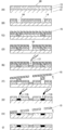
- FIG. 1 is a schematic diagram showing the procedure of the patterning method of the present invention.
- FIG. 1A shows a structure 10 in which a biocompatible polymer layer 2 is formed on a substrate 1 and a resin layer 3 is formed on the biocompatible polymer layer 2.
- the biocompatible polymer layer 2 and the resin layer 3 are removed so that the spots 4 are formed in a desired pattern and the biocompatible polymer layer 2 remains, and a part of the substrate is exposed, A spot 4 is formed (FIG. 1B).
- the resin layer 3 is removed (FIG. 1 (C)), and the structure 10 in which the biocompatible polymer layer 2 and the spots 4 are arranged in a desired pattern on the substrate is created.
- FIG. 2 is a schematic diagram showing another procedure of the patterning method of the present invention.
- FIG. 2A shows a structure in which a biocompatible polymer layer 12 is formed on a substrate 11 and a first resin layer 13 is formed on the biocompatible polymer layer 12.
- the biocompatible polymer layer 12 and the first resin layer 13 are removed so that the first spot 14 is formed in a desired pattern, and a part of the substrate 11 is exposed to form the first spot 14. (FIG. 2B).
- a second resin layer 15 is formed on the substrate at the location of the first spot 14 and the remaining first resin layer 13 so as to fill the first spot 14 (FIG. 2C).
- the biocompatible polymer layer 12, the first resin layer 13, and the second resin layer 15 are removed so that the second spots 16 are formed in a desired pattern.
- the second spot 16 where the substrate 11 is exposed is formed (FIG. 2D).
- the second biological material 17 may be applied to the second spot 16 (FIG. 2E).
- the biological material is depicted as being pipetted, but this is only exemplary and may be performed by any method known to those skilled in the art.
- the second biological material 17 is removed at the stage of FIG. 2E where only the second spot is exposed. It is preferable to apply.
- a dam (not shown) is provided on the second resin layer 15, and the second biological material is poured by flowing a fluid containing the second biological material using the entire region surrounded by the dam as a reservoir. In some cases, the substrate may be brought into contact with the second spot. After applying the second biological material 17 to the second spot 16, the second resin layer 15 is removed (FIG. 2F). Then, the substrate at the location of the first spot 14 covered with the second resin layer is exposed again.
- the first biological material 18 may be applied to the first spot 14 in the stage of FIG. As with the application of the second biological material, the application of the first biological material may be performed by any method known to those skilled in the art. Thereafter, when the first resin layer 13 is removed (FIG. 2H), the biocompatible polymer layer 12, the first spot 14, and the second spot 16 are arranged in a desired pattern on the substrate. The structured body 20 is created (FIG. 2I).
- the first biological material is applied to the first spot 14 after the first resin layer 13 is removed. If the first biological material is applied in such a way that the application location cannot be accurately specified, the second biological material in the second spot 17 may be mixed with the first biological material. There is. In the case of adopting such an application method, for example, by adding a component that neutralizes or inactivates the first biological material to the second biological material, the influence of mixing is reduced or reduced. Can be resolved.
- the first biological material is a lectin
- a sugar that specifically binds to the lectin is included in the second biological material.
- the first biological material is an antibody
- an antigen that specifically binds to the antibody is preferably included in the second biological material.
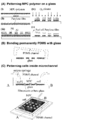
- FIG. 3 it is a schematic diagram which shows the procedure of preparation of the microchannel device using the patterning method of this invention.
- a layer of biocompatible polymer MPC polymer
- a layer of resin polyparaxylylene
- Is formed FIG. 3 (A) (ii)
- Aluminum and an optical sacrificial layer are formed thereon (FIGS. 3A and 3).
- FIG. 3 (A) (iv) The polyparaxylylene resin layer is peeled off (FIGS. 3A and 3V), and the glass substrate on which the biocompatible polymer (MPC polymer) pattern is formed is exposed.
- a micro-channel made of polydimethylsiloxane (PDMS) by a conventional microfabrication technique is prepared and irradiated with O 2 plasma (FIG. 3 (A) (v))
- a biocompatible polymer (MPC polymer) ) Is permanently and watertightly attached to the glass substrate on which the pattern of FIG. 3 is formed (FIG. 3B).
- FIG. 3C shows a state in which cells and other biological materials are added to the completed microchannel device of the present invention.
- a cross-sectional schematic view taken along the line AB in FIG. 3C is the bottom of FIG.
- a substance that promotes cell-substrate adhesion such as fibronectin or collagen may be applied to the microchannel device.
- MPC polymer layer was formed on the surface of a glass substrate by spin coating. Next, a 2 ⁇ m-thick parylene layer was deposited on the MPC polymer. Then, using a photoresist and aluminum as a mask for dry etching, the parylene layer and MPC polymer layer at desired positions were removed by O 2 plasma. Thereafter, the parylene layer was peeled off to expose the MPC polymer layer. Since the MPC polymer suppresses non-specific adsorption of the biological material to the substrate, the biological material is preferentially held in the spot where the MPC polymer layer is removed and the glass substrate is exposed. When the portion where the glass substrate is exposed is disposed in the flow path of the microchannel device, the microchannel is formed by laminating polydimethylsiloxane (PDMS) on the glass substrate according to a conventional method and passing through the portion. Form.
- PDMS polydimethylsiloxane
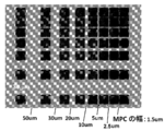
- FIG. 5 is a fluorescent photograph showing the result of patterning using an MPC polymer to which rhodamine has been added in advance. Patterning was possible with an accuracy of MPC polymer width up to 1.5 ⁇ m. In the present invention, since the biocompatible polymer layer and the resin layer are removed by the photolithography method, the MPC polymer can be patterned with the same accuracy as the photolithography method.
- the cells used are bovine vascular endothelial cells. 37 ° C using Dulbecco's modified Eagle's medium (DMEM, 11885, Gibco) supplemented with 10% fetal bovine serum (FBS, F7524, SIGMA) and 5% penicillin-streptomycin solution (p4333, SIGMA) The cells were cultured in a 5% CO 2 atmosphere.
- DMEM Dulbecco's modified Eagle's medium
- FBS fetal bovine serum
- SIGMA penicillin-streptomycin solution
- FIG. 6 is an optical micrograph showing the arrangement of cells after 4 hours of culturing on a structure containing a patterned MPC polymer layer from which the spot of the diameter described in each frame has been removed. As shown in FIG. 6, almost no cells were present on the MPC polymer layer, and the cells were arranged only at the spots where the MPC polymer was removed. The cells were almost uniformly distributed in spots having diameters of 200 ⁇ m (upper left) and 100 ⁇ m (upper right). The smaller the spot diameter, the smaller the number of cells per spot. One cell was placed in each spot at a diameter of 20 ⁇ m (lower right). In this state, it was observed that the cells were not able to extend due to substrate adhesion and were rounded.
- FIG. 7 is an optical micrograph showing the arrangement of cells after 3 days of culturing on a structure containing a patterned MPC polymer layer from which strip-like spots having a width described in each frame have been removed.
- cells were only placed at spots where the MPC polymer was removed.
- the spot width was 50 ⁇ m (lower frame)
- 4 to 5 cells were aligned in the longitudinal direction of the spot.
- the spot width was 5 ⁇ m
- the cells were aligned one by one in a row.
- the spot width was 3 ⁇ m, the cells were elongated and oriented.
- the cells proliferate well in a state where the cells are arranged in a desired orientation pattern in an environment where the patterning treatment of the present invention has been performed.
- FIG. 8 is a series of photographs taken of the rotation of one flagella.
- FIG. 9 is a graph showing the relationship between the size of the spot where the glass substrate is exposed and the ratio of the adsorbed flagella rotating. The smaller the spot size, the greater the percentage of flagella rotating, and 73% of the flagella rotated when the spot diameter was 5 ⁇ m. The rotation speed of flagella adsorbed on the spot was 0.5 to 3.0 rps.
- FIG. 10 is a graph showing the control of the flagellar rotation speed by solution conversion that perfuses the channel in the microchannel device.
- Step 2 the flagella that did not convert the buffer increased in rotational speed by about 20%, whereas the buffered flagella decreased in rotational speed to less than half of the original. From this, it can be said that when the Ca ion concentration in the buffer increases, the rotational speed of flagella fixed to the substrate decreases.
- the actual measurement value of the rotation speed was an average of 2.0 rps at Step 1 and an average of 0.8 rps at Step 2.
- Step 3 the flagella that did not convert the buffer decreased in rotational speed to about 60%.
Landscapes
- Health & Medical Sciences (AREA)
- Chemical & Material Sciences (AREA)
- Wood Science & Technology (AREA)
- Organic Chemistry (AREA)
- Life Sciences & Earth Sciences (AREA)
- Engineering & Computer Science (AREA)
- Bioinformatics & Cheminformatics (AREA)
- Zoology (AREA)
- Biomedical Technology (AREA)
- Sustainable Development (AREA)
- Microbiology (AREA)
- Biotechnology (AREA)
- Biochemistry (AREA)
- General Engineering & Computer Science (AREA)
- General Health & Medical Sciences (AREA)
- Genetics & Genomics (AREA)
- Clinical Laboratory Science (AREA)
- Immunology (AREA)
- Dispersion Chemistry (AREA)
- Apparatus Associated With Microorganisms And Enzymes (AREA)
- Micromachines (AREA)
Abstract
生物学的材料の非特異性吸着を抑制する生体適合性ポリマーを、マイクロ流路デバイスの流路内を含む基板上でミクロンオーダーの高精度でパターンニングする方法を開発すること。 本発明は生体適合性ポリマーのパターンニング方法を提供する。前記生体適合性ポリマーのパターンニング方法は、生体適合性ポリマーの層を形成するステップと、前記生体適合性ポリマーの層の上に樹脂の層を形成するステップと、前記生体適合性ポリマーの層と樹脂の層とが除去されて基板が露出した、スポットを形成するステップと、前記樹脂の層を除去するステップとを含む。本発明は、基板と、本発明の方法によってパターンニングされた生体適合性ポリマーの層及び前記スポットとを含む、構造体及びマイクロ流路デバイスを提供する。
Description
本発明は、生体適合性ポリマーのパターンニング方法と、該方法によってパターンニングされた生体適合性ポリマーの層を含む構造体及びマイクロ流路デバイスとに関し、より具体的には、パリレン樹脂の引き剥がし法を用いて生体適合性ポリマーをマイクロ流路デバイスの流路内でミクロンオーダーの高精度でパターンニングする方法と、該方法によってパターンニングされた生体適合性ポリマーの層と、該生体適合性ポリマーの層が除去されて前記基板が露出したスポットと、該スポットに選択的に吸着された生物学的材料を含む構造体及びマイクロ流路デバイスに関する。
近年、シリコン、ガラス、ポリマー等の基板上に微細加工を施して、細胞、特に単一細胞のパターンニングを行う技術の開発が進んでいる。かかる技術は、再生医療などの分野で細胞の機能解析や培養環境の最適条件を知るうえで重要な技術である。また、細胞、タンパク質、DNA等の生物学的材料を基板上にパターンニングし、マイクロ流路と組み合わせて、生物学的材料の分析化学システムやセンサーに応用する研究も盛んにおこなわれるようになってきた。従来のパターンニング方法には、例えば、リン脂質極性基を側鎖に有する2-メタクリロイルオキシエチルホスホリルコリン(以下、「MPC」という。)のような生体適合性ポリマーを利用し、基板表面をマイクロパターン化し、生物学的材料の非特異性吸着を抑制する方法が用いられている。しかし、基板上でミクロンオーダーの高精度でパターンニングする方法と、マイクロ流路デバイスの流路内でパターンニングする方法とはいずれも確立されていない。
S.Takeuchiら、MEMS2004、pp208-210、(2004) B.Llicら、Biomedical Microdevices、2、4、317-322、(2000)
S.Takeuchiら、MEMS2004、pp208-210、(2004) B.Llicら、Biomedical Microdevices、2、4、317-322、(2000)
そこで、生物学的材料の非特異性吸着を抑制する生体適合性ポリマーを、マイクロ流路デバイスの流路内を含む基板上でミクロンオーダーの高精度でパターンニングする方法を開発する必要がある。
本発明は生体適合性ポリマーのパターンニング方法を提供する。前記生体適合性ポリマーのパターンニング方法は、生体適合性ポリマーの層を形成するステップと、前記生体適合性ポリマーの層の上に樹脂の層を形成するステップと、前記生体適合性ポリマーの層と樹脂の層とが除去されて基板が露出した、スポットを形成するステップと、前記樹脂の層を除去するステップとを含む。
本発明の生体適合性ポリマーのパターンニング方法は、生体適合性ポリマーの層を形成するステップと、前記生体適合性ポリマーの層の上に第1樹脂の層を形成するステップと、前記生体適合性ポリマーの層と第1樹脂の層とが除去されて基板が露出した、第1スポットを形成するステップと、残存する第1樹脂の層と、第1スポットの場所の基板との上に第2樹脂の層を形成するステップと、前記生体適合性ポリマーの層と、第1樹脂の層と、第2樹脂の層との全てが除去されて基板が露出した、第2スポットを形成するステップと、第2樹脂の層を除去するステップとを含む場合がある。
本発明の生体適合性ポリマーのパターンニング方法において、前記生体適合性ポリマーは、生物学的材料との非特異性吸着を抑制する両親媒性ポリマーの場合がある。
本発明の生体適合性ポリマーのパターンニング方法において、前記生体適合性ポリマーは2-メタクリロイルオキシエチルホスホリルコリンの場合がある。
本発明の生体適合性ポリマーのパターンニング方法において、前記基板は光透過性を有する場合がある。
本発明の生体適合性ポリマーのパターンニング方法において、前記基板はガラスの場合がある。
本発明の生体適合性ポリマーのパターンニング方法において、前記樹脂はポリパラキシリレンの場合がある。
本発明の生体適合性ポリマーのパターンニング方法において、前記生体適合性ポリマー及び樹脂の層の一部を除去して基板が露出したスポットを形成するステップは、ドライエッチング法により実行される場合がある。
本発明は、基板と、本発明の方法によってパターンニングされた生体適合性ポリマーの層及び前記スポットとを含む、構造体を提供する。
本発明の構造体は、前記基板を支持部を介して切断可能なように保持する基材を含む場合がある。
本発明の構造体は、前記支持部で前記基材から前記基板が切断することによって生じる前記基板の切断面を含み、該切断面は前記基板が露出している場合がある。
本発明の構造体は、前記基板上に設けられたマイクロ流路を含み、該マイクロ流路は前記スポットを通る場合がある。
本発明の構造体において、前記マイクロ流路はポリジメチルシロキサンで作成される場合がある。
本発明の構造体は、前記スポットに結合した生物学的材料を含む場合がある。
本発明の構造体は、基板と、該基板上に形成される、本発明の方法によってパターンニングされた生体適合性ポリマーの層、第1スポット及び第2スポットとを含む場合がある。前記生体適合性ポリマーの層、第1スポット及び第2スポットは、生体適合性ポリマーの層を形成するステップと、前記生体適合性ポリマーの層の上に第1樹脂の層を形成するステップと、前記生体適合性ポリマーの層と、第1樹脂の層とが除去されて基板が露出した、第1スポットを形成するステップと、第1樹脂の層の上に第2樹脂の層を形成するステップと、前記生体適合性ポリマーの層と、第1樹脂の層と、第2樹脂の層とが除去されて基板が露出した、第2スポットを形成するステップと、第2樹脂の層を除去するステップとを含む方法によってパターンニングされる。
本発明の構造体は、第1スポットに結合した第1生物学的材料と、第2スポットに結合した第2生物学的材料とを含む場合がある。
本発明の構造体において、前記生物学的材料の少なくとも1つは細胞の場合がある。
本発明の構造体において、前記スポットのそれぞれに1個の細胞が配置される場合がある。
本発明の構造体において、前記生物学的材料の少なくとも1つは特異的結合パートナーの場合がある。
本発明の構造体において、第1生物学的材料は第1特異的結合パートナーで、第2生物学的材料は第2特異的結合パートナーの場合がある。
本発明はマイクロ流路デバイスを提供する。前記マイクロ流路デバイスは、基板と、該基板上に形成される生体適合性ポリマーの層と、該生体適合性ポリマーの層が除去されて前記基板が露出した第1及び第2スポットと、前記スポットを通るマイクロ流路と、第1及び第2スポットのそれぞれに結合した第1及び第2特異的結合パートナーと、第1及び第2特異的結合パートナーと特異的に結合する第1及び第2細胞とを含む。
本発明のマイクロ流路デバイスにおいて、第1及び第2スポットのそれぞれに第1及び第2細胞が1個配置される場合がある。
本発明の構造体において、前記生物学的材料の少なくとも1つは運動可能なオルガネラの場合がある。
本発明の構造体において、前記運動可能なオルガネラは単離された鞭毛の場合がある。
本発明の構造体において、前記スポットのそれぞれに前記単離された鞭毛が1個配置される場合がある。
本発明はマイクロ流路デバイスを提供する。前記マイクロ流路デバイスは、基板と、該基板上に形成される生体適合性ポリマーの層と、該生体適合性ポリマーの層が除去されて前記基板が露出したスポットと、該スポットを通るマイクロ流路と、前記スポットに配置された運動可能なオルガネラとを含むマイクロ流路デバイスであって、前記オルガネラの運動は前記マイクロ流路を潅流するバッファーを変えることによって制御される。
本発明のマイクロ流路デバイスにおいて、前記オルガネラは単離された鞭毛の場合がある。
本発明はマイクロ流路デバイスを提供する。前記マイクロ流路デバイスは、基板上に形成された生体適合性ポリマーの層が除去されて前記基板が露出したスポットに配置された鞭毛を含み、該鞭毛を回転させることによって前記スポットを通るマイクロ流路内を潅流する液体を輸送又は撹拌する。
本発明のマイクロ流路デバイスにおいて、前記スポットのそれぞれに1個の鞭毛が配置される場合がある。
本発明の生体適合性ポリマーのパターンニング方法は、第N-1樹脂の層の上に第N樹脂の層を形成するステップ(Nは3以上の自然数)と、前記生体適合性ポリマーの層と、第1樹脂の層ないし第N樹脂の層とが除去されて基板が露出した、第Nスポットを形成するステップと、第N-1樹脂の層を除去するステップとを含む場合がある。本発明の構造体及び/又はマイクロ流路デバイスは、基板と、該基板上に形成される、前記方法によってパターンニングされた生体適合性ポリマーの層、第1スポット、第2スポット、・・・、第Nスポットとを含む場合がある。また本発明の構造体及び/又はマイクロ流路デバイスは、第1スポットに結合した第1生物学的材料と、第2スポットに結合した第2生物学的材料と、・・・、第Nスポットに結合した第N生物学的材料とを含む場合がある。さらに、第N生物学的材料が第N特異的結合パートナーであって、第1特異的結合パートナー、第2特異的結合パートナー、・・・、第N特異的結合パートナーがそれぞれ異なる特異性をもって結合するため、N種類の異なる細胞の懸濁液に前記構造体及び/又はマイクロ流路デバイスを接触させることにより、一度にN種類の細胞が所望のパターンで配置された構造体及び/又はマイクロ流路デバイスを作成することができる。以下、本明細書では樹脂の層及びスポットが1種類又は2種類の場合について説明するが、本発明の範囲は3種類以上の樹脂の層及びスポットを有する場合を排除しない。すなわち、3種類以上の樹脂の層及びスポットを有する場合であっても、本明細書に添付される特許請求の範囲に記載された発明に該当する場合には本発明の範囲に属する。
本明細書において、生体適合性ポリマーとは、細胞、細胞内オルガネラ及び/又は生体分子のような生物学的材料を含むマイクロ流路デバイスに用いられるときに前記生物学的材料に対して特に有害な影響を及ぼさない高分子化合物をいう。本発明の生体適合性ポリマーは、生物学的材料との非特異性吸着を抑制する場合がある。かかる生体適合性ポリマーが本発明の構造体又はマイクロ流路デバイスの基板上にコーティングされ、該生体適合性ポリマーの層が形成されるとき、生物学的材料は前記構造体又はマイクロ流路デバイスに固着せず、容易に洗浄除去することができる。生体適合性ポリマーは、生物学的材料との非特異性吸着を抑制する両親媒性ポリマーが好ましく、2-メタクリロイルオキシエチルホスホリルコリンがより好ましい。また、生物学的材料が細胞外オルガネラ又は生体分子の場合には、ウシ血清アルブミンのようなタンパク質を生体適合性ポリマーとしいて用いることができる。
本明細書における生物学的材料とは、生物に由来するいずれかの材料を指し、生物個体、臓器、組織及び細胞と、鞭毛、繊毛、ミトコンドリア、葉緑体、染色体、分裂装置、リソソーム、ゴルジ体等の細胞内オルガネラと、ウイルス、DNA複製酵素複合体、転写/RNAプロセッシング複合体、リボソーム、イオンチャンネル、細胞表面レセプター複合体等の分子集合体と、核酸、タンパク質、炭水化物等の生体高分子と、ホルモン、セカンドメッセンジャー、酵素基質、代謝中間体等の他の生物学的材料と相互作用を起こす全ての化合物とを含むが、これらに限定されない。
本発明の運動可能なオルガネラは、鞭毛と、繊毛と、分裂装置と、仮足又は偽足とを含むが、これらに限られない、形態又は位置が変化する全てのオルガネラをいう。好ましい運動可能なオルガネラは鞭毛であり、クラミドモナス鞭毛が特に好ましい。
本発明で用いられる特異的結合パートナーは、レクチンと、レクチンの可溶性断片と、ポリクローナル抗体又はモノクローナル抗体と、該抗体の抗原結合断片と、該抗原結合断片を含むキメラ抗体又は組換え抗体とからなるグループから選択される場合がある。抗体の抗原結合断片は、抗原結合に参加する抗体の部分を指す。前記抗原結合部位は、重(H)鎖及び軽(L)鎖のN末端の可変(V)領域のアミノ酸残基によって形成される。
抗体は、当業者に知られたさまざまな技術によって調製される場合がある。例えば、Harlow及びLane、Antibodies: A Laboratory Manual、Cold Spring Harbor Laboratory、1988を参照せよ。
本発明で用いられるポリクローナル抗体は、細胞表面抗原マーカーか、これらの断片かを免疫原として、ほ乳類(例えば、マウス、ラット、ウサギ、ヒツジ又はヤギ)又は鳥類(例えばニワトリ)のいずれかの動物宿主に注射される。細胞表面抗原マーカーの断片を免疫原とする場合には、ウシ血清アルブミン又はスカシ貝ヘモシアニン(keyhole limpet hemocyanine)のような担体タンパク質と連結される場合に優れた免疫応答が誘発される場合がある。前記免疫原は、1回又は2回以上のブースター免疫を取り込んだ予め定められたスケジュールに従って、前記動物宿主に注射されることが好ましい。前記免疫原は、完全又は不完全フロイントアジュバントその他の免疫増強剤に混合して前記動物宿主に注射される場合がある。本発明のポリクローナル抗体は、かかる抗血清から、例えば適当な固体支持体に結合された細胞表面抗原マーカーか、これらの断片かを用いるアフィニティクロマトグラフィーによって精製される場合がある。
本発明で用いられるモノクローナル抗体は、Kohler及びMilstein、Eur.J.Immunol.6:511-519、1976の技術と、その改良技術を用いて調製される場合がある。これらの方法は、所望の特異性を有する抗体を産生できる不死性細胞株の調製を伴う。かかる細胞株は上記のとおり免疫された動物宿主由来の脾臓細胞から作成される場合がある。前記脾臓細胞は、さまざまな方法で不死化され、抗体産生能を有する不死化細胞株が調製される。前記脾臓細胞は、例えば、前記免疫された動物と同種かあるいは異種の動物由来のミエローマ細胞との融合によって不死化される。当業者に周知のさまざまな融合技術を用いる場合がある。例えば、前記脾臓細胞とミエローマ細胞とは非イオン性界面活性剤と数分間混合され、それからハイブリッド細胞の増殖は支持するがミエローマ細胞の増殖は支持しない選択培地に低濃度でプレートされる。好ましい選択技術はHAT(ヒポキサンチン、アミノプテリン、チミジン)選択を用いる。通常約1ないし2週間の十分な時間の後、ハイブリッドのコロニーが観察される。シングルコロニーが選択され、その培養上清が前記ポリペプチドに対する結合活性についてテストされる。反応性及び特異性が高いハイブリドーマが好ましい。限界希釈法によるクローニングを繰り返すことにより、反応性及び特異的が高い抗体を安定的に大量に産生するハイブリドーマのクローンが選択される。モノクローナル抗体は増殖中の選択されたハイブリドーマクローン由来の細胞株のコロニーの上清から単離される場合がある。さらに、マウスのような適当な脊椎動物宿主の腹腔内に前記ハイブリドーマ細胞株を注射するような、収率を向上させるためのさまざまな技術が用いられる場合がある。モノクローナル抗体は前記ハイブリドーマ細胞腹水又は血液から回収される場合がある。汚染物は、クロマトグラフィー、ゲルろ過、沈殿及び抽出のような従来技術によって前記抗体から除去される場合がある。
本発明で用いられる抗体の抗原結合断片は、それぞれタンパク質分解酵素パパイン又はペプシンでインタクトなポリクローナル抗体又はモノクローナル抗体を分解して得られるFab断片又はF(ab’)2断片の他、天然抗体分子の抗原認識能及び結合能の多くを保持する抗原結合部位を含む非共有結合的なVH及びVL領域のヘテロ2量体を含むFv断片を含む。
本発明で用いられる組換え抗体は、適当な細菌宿主への形質転換か、適当なほ乳類細胞宿主へのトランスフェクションかを含む抗体遺伝子の発現クローニングによって調製される場合がある。本発明で用いられるキメラ抗体は、前記本発明の組換え抗体の抗原結合部位が細胞表面抗原マーカーと特異的に結合できるように同種又は異種の抗体の定常ドメインによって支持された融合タンパク質である。本発明で用いられるキメラ抗体には、抗体軽鎖可変領域(VL)に操作可能に連結された抗体重鎖可変領域(VH)を含む短鎖可変部抗体(scFv)と、ラクダ科(Camelidae、ラクダ、ヒトコブラクダ、ラマを含む)の動物が産生する軽鎖がないIgGのクラスであるラクダ重鎖抗体(HCAb)又はその重鎖可変部ドメイン(VHH)とを含む。本発明の組換え抗体は原核生物及び真核生物由来の遺伝子発現システムを用いて大量に調製することができる。
本明細書において、生体適合性ポリマー、樹脂等の層を形成する際には、スピン塗布法、真空蒸着法その他当業者に周知のいかなる方法によって、適用、塗布、蒸着又はコーティングされてもかまわない。
本明細書において、生体適合性ポリマーの層の上に形成される樹脂の層は、本発明のスポットを形成するステップにおいて、該スポットで露出される場所以外の前記基板の上の前記生体適合性ポリマーの層を保護することが可能であること、及び、その後必要に応じて、前記樹脂の層を除去することが可能であることを条件として、いかなる材料でできていてもかまわない。本発明の第1樹脂の層の上に第2樹脂の層を形成するステップを含む、生体適合性ポリマーのパターンニング方法においては、第2スポットに第2生物学的材料が結合した後、第2生物学的材料と、残存する第1樹脂及び前記生体適合性ポリマーの層と、第1スポットの基板の表面とにいかなる影響を与えることなく第2樹脂の層を除去することができることが望ましい。また、第2樹脂の層を除去してから、第1スポットに第1生物学的材料が結合した後で、第1生物学的材料と、残存する前記生体適合性ポリマーの層とにいかなる影響を与えることなく第1樹脂の層を除去することができることが望ましい。前記樹脂の層を除去することは、前記樹脂の層を引き剥がすこと(リフトオフ)によって実行される場合がある。好ましい樹脂はポリパラキシリレン(商品名:パリレン)である。第1樹脂と第2樹脂とは、同一の物質の場合もあれば、異なる物質の場合もある。
本発明の生体適合性ポリマー及び樹脂の層が除去されて基板が露出したスポットを形成するステップは、光リソグラフィ法、ドライエッチング法その他当業者に周知のいかなる方法のいかなる組み合わせによって実行されてもかまわない。好ましいやり方は、O2プラズマを用いるドライエッチング法である。
本明細書において、スポットとは、基板の上にいったん形成された生体適合性ポリマーの層が除去されて、基板が露出した場所をいう。前記スポットと、該スポットが形成された後に残存する生体適合性ポリマーの層とは、本発明のパターンニング方法を利用して、所望の数、形状及び/又は寸法にすることができる。前記スポット及び/又は生体適合性ポリマーの層の寸法は1μm以上のいかなる寸法でも作成することができる。これによって、細菌、動植物細胞その他の生物学的材料をその寸法に近い間隔(例えば、数μmないし十μm)で本発明の構造体及び/又はマイクロ流路デバイス上に配置することができるので、細胞を高密度でパターンニングすることが可能になる。第1スポットは、第1樹脂及び生体適合性ポリマーの層が除去されて形成されるが、いったん露出した基板はその後第2樹脂の層に覆われ、第2スポットが形成されてから第2樹脂の層が除去されて、もう一度基板が露出する。これに対し第2スポットは、露出した基板が樹脂の層に覆われることは起こらない点でのみ第1スポットと異なる。第1スポットと第2スポットとの区別は、スポットの位置、形状及び/又は寸法によるものではない。
1、11 基板
2、12 生体適合性ポリマーの層
3 樹脂の層
4 スポット
10、20 構造体
13 第1樹脂の層
14 第1スポット
15 第2樹脂の層
16 第2スポット
17 第2生物学的材料
18 第1生物学的材料
2、12 生体適合性ポリマーの層
3 樹脂の層
4 スポット
10、20 構造体
13 第1樹脂の層
14 第1スポット
15 第2樹脂の層
16 第2スポット
17 第2生物学的材料
18 第1生物学的材料
図1を参照して、本発明のある実施態様を説明する。図1は本発明のパターンニング方法の手順を示す模式図である。図1(A)には、基板1の上に生体適合性ポリマーの層2が形成され、生体適合性ポリマーの層2の上に樹脂の層3が形成された構造体10が示される。所望のパターンでスポット4が形成されて生体適合性ポリマーの層2が残存するように、生体適合性ポリマーの層2と、前記樹脂の層3とが除去され、基板の一部が露出し、スポット4が形成される(図1(B))。その後、樹脂の層3が除去されて(図1(C))、生体適合性ポリマーの層2と、スポット4とが所望のパターンで基板上に配置された構造体10が作成される。
図2を参照して、本発明の別の実施態様を説明する。図2は本発明のパターンニング方法の別の手順を示す模式図である。図2(A)には、基板11の上に生体適合性ポリマーの層12が形成され、生体適合性ポリマーの層12の上に第1樹脂の層13が形成された構造体が示される。所望のパターンで第1スポット14が形成されるように、生体適合性ポリマーの層12と、第1樹脂の層13とが除去され、基板11の一部が露出し、第1スポット14が形成される(図2(B))。その後、第1スポット14を埋めるように第1スポット14の場所の基板と、残存した第1樹脂の層13との上に第2樹脂の層15が形成される(図2(C))。
つぎに、所望のパターンで第2スポット16が形成されるように、生体適合性ポリマーの層12と、第1樹脂の層13と、第2樹脂の層15とが除去される。このようにして基板11が露出した第2スポット16が形成される(図2(D))。この段階で第2スポット16に第2生物学的材料17が適用される場合がある(図2(E))。図2(E)及び(G)では生物学的材料がピペットで滴下されるように描かれるが、これは例示にすぎず、当業者に周知のいかなる方法によって実行されてもかまわない。適用する場所を正確に指定することができないやり方、例えば、蒸着、噴霧その他のやり方では、第2スポットだけしか基板が露出していない図2(E)の段階で第2生物学的材料17を適用することが好ましい。第2樹脂の層15の上に堰堤(図示されない)を設けて、該堰堤で囲まれた領域全体を液溜めとして第2生物学的材料を含む流体を流し込むことによって第2生物学的材料を第2スポットの基板と接触させる場合もある。第2スポット16に第2生物学的材料17を適用した後で、第2樹脂の層15が除去される(図2(F))。すると、第2樹脂の層で覆われていた第1スポット14の場所の基板がふたたび露出する。
図2(G)の段階で第1生物学的材料18を第1スポット14に適用する場合がある。第2生物学的材料の適用の場合と同じく第1生物学的材料の適用においても、当業者に周知のいかなる方法によって実行されてもかまわない。その後、第1樹脂の層13が除去される(図2(H))と、生体適合性ポリマーの層12と、第1スポット14と、第2スポット16とが所望のパターンで基板上に配置された構造体20が作成される(図2(I))。
第1樹脂の層13が除去されてから、第1生物学的材料を第1スポット14に適用する場合も考えられる。適用する場所を正確に指定することができないやり方で第1生物学的材料が適用される場合には、第2スポット17の第2生物学的材料に第1生物学的材料が混入する可能性がある。このような適用方法を採用する場合には、例えば、第2生物学的材料に、第1生物学的材料を中和又は不活性化する成分を添加しておくことで混入による影響を軽減又は解消することができる。第1生物学的材料がレクチンの場合には、該レクチンと特異的に結合する糖を第2生物学的材料に含めることが好ましい。第1生物学的材料が抗体の場合には、該抗体と特異的に結合する抗原を第2生物学的材料に含めることが好ましい。
図3を参照して、本発明のパターンニング方法を利用するマイクロ流路デバイスの作成の手順を示す模式図である。ガラス製基板の上に生体適合性ポリマー(MPCポリマー)の層が形成され(図3(A)(i))、該生体適合性ポリマーの層の上に、樹脂(ポリパラキシリレン)の層が形成される(図3(A)(ii))。その上にアルミニウム及び光犠牲層が形成される(図3(A)(iii))。アルミニウム及び光犠牲層の上からO2プラズマが照射されることによって、アルミニウム及び光犠牲層で保護されていない部分の樹脂及び生体適合性ポリマーの層が除去され、ガラス基板が露出したスポットが形成される(図3(A)(iv))。ポリパラキシリレンの樹脂の層が剥ぎ取られ(図3(A)(v))、生体適合性ポリマー(MPCポリマー)のパターンが形成されたガラス基板が露出する。一方で、従来の微細加工技術によるポリジメチルシロキサン(PDMS)によるマイクロ流路が用意され、O2プラズマが照射された後、(図3(A)(v))、生体適合性ポリマー(MPCポリマー)のパターンが形成されたガラス基板に永久的に、かつ、水密に貼り付けられる(図3(B))。このようにして、マイクロ流路の潅流のために、マイクロシリンジ等の送液手段を介して1個又は2個以上の液体供給源に接続されるインレットと、廃液溜めに接続されるアウトレットとを更に備えた、本発明のマイクロ流路デバイスが作成される。図3(C)は完成した本発明のマイクロ流路デバイスに細胞その他の生物学的材料を添加した様子を示す。図3(C)上のA-B間の断面模式図が図3(C)下である。マイクロシリンジを通じて細胞の懸濁液をデバイス内部に流入させると、生体適合性ポリマー(MPCポリマー)層は細胞の基質接着を阻害するため、該生体適合性ポリマー(MPCポリマー)層の上に細胞が付着することはできない。そこで、前記生体適合性ポリマー(MPCポリマー)層が存在せずガラス基板が露出した部分にのみ細胞が付着する。このようにして作成されるマイクロ流路デバイス内のスポットに細胞その他の生物学的材料が配置される。なお、前記マイクロ流路デバイスに細胞懸濁液を添加する前に、フィブロネクチン、コラーゲン等の細胞-基質間接着を促進する物質を前記マイクロ流路デバイスに適用する場合もある。
以下に実施例を示すが、これらは実施態様の例示を意図しており本発明の範囲を限定することは意図しない。
MPCポリマーによるガラス基板への生物学的材料の非特異性吸着の抑制
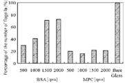
ガラス基板への生物学的材料の非特異性吸着をMPCポリマーがどの程度抑制するかを検討するために、さまざまな回転速度でスピン塗布されたMPCポリマー及びウシ血清アルブミン(BSA)でコーティングされたガラス表面と、無処理で露出したガラス表面とにクラミドモナス鞭毛を適用した。前記クラミドモナス鞭毛は、3-4日液体培養したクラミドモナスにジブカイン-塩酸を添加した後、超遠心により回収した(S.Aoyamaら、Biophysical J.、89:3261-3268(2005))。その結果、図3に示すとおり、BSAではスピン塗布する回転速度が低いほど鞭毛の吸着が減少した。MPCポリマーでは、回転速度が最高の条件でもいかなる条件のBSAよりも鞭毛の吸着が少なかった。この結果からMPCポリマーは、生物学的材料の吸着を抑制する活性が強力であることがわかった。そこで、MPCポリマーのパターンニングによって生物学的材料を所望のパターンで配置できることが期待される。
ガラス基板への生物学的材料の非特異性吸着をMPCポリマーがどの程度抑制するかを検討するために、さまざまな回転速度でスピン塗布されたMPCポリマー及びウシ血清アルブミン(BSA)でコーティングされたガラス表面と、無処理で露出したガラス表面とにクラミドモナス鞭毛を適用した。前記クラミドモナス鞭毛は、3-4日液体培養したクラミドモナスにジブカイン-塩酸を添加した後、超遠心により回収した(S.Aoyamaら、Biophysical J.、89:3261-3268(2005))。その結果、図3に示すとおり、BSAではスピン塗布する回転速度が低いほど鞭毛の吸着が減少した。MPCポリマーでは、回転速度が最高の条件でもいかなる条件のBSAよりも鞭毛の吸着が少なかった。この結果からMPCポリマーは、生物学的材料の吸着を抑制する活性が強力であることがわかった。そこで、MPCポリマーのパターンニングによって生物学的材料を所望のパターンで配置できることが期待される。
パリレン樹脂リフトオフ法によるMPCポリマーの高精度パターンニング
スピン塗布法によりガラス基板の表面にMPCポリマー層を形成した。つぎに、前記MPCポリマーの上に2μm厚のパリレン層を蒸着した。そして、ドライエッチングのマスクとしてフォトレジスト及びアルミニウムを用い、O2プラズマにより所望の位置の前記パリレン層及びMPCポリマー層を除去した。その後、パリレン層を引き剥がしてMPCポリマー層を露出させた。MPCポリマーは生物学的材料の基板への非特異性吸着を抑制するため、生物学的材料はMPCポリマー層が除去されてガラス基板が露出したスポットに優占的に保持される。ガラス基板が露出した前記部位をマイクロ流路デバイスの流路内に配置する場合には、常法に従ってポリジメチルシロキサン(PDMS)を前記ガラス基板上に積層して、前記部位を通過するマイクロ流路を形成する。
スピン塗布法によりガラス基板の表面にMPCポリマー層を形成した。つぎに、前記MPCポリマーの上に2μm厚のパリレン層を蒸着した。そして、ドライエッチングのマスクとしてフォトレジスト及びアルミニウムを用い、O2プラズマにより所望の位置の前記パリレン層及びMPCポリマー層を除去した。その後、パリレン層を引き剥がしてMPCポリマー層を露出させた。MPCポリマーは生物学的材料の基板への非特異性吸着を抑制するため、生物学的材料はMPCポリマー層が除去されてガラス基板が露出したスポットに優占的に保持される。ガラス基板が露出した前記部位をマイクロ流路デバイスの流路内に配置する場合には、常法に従ってポリジメチルシロキサン(PDMS)を前記ガラス基板上に積層して、前記部位を通過するマイクロ流路を形成する。
図5は、予めローダミンを添加したMPCポリマーを用いてパターンニングした結果を示す蛍光写真である。MPCポリマーの幅が1.5μmまでの精度でパターンニングすることができた。本発明では光リソグラフィ法で生体適合性ポリマーの層及び樹脂の層を除去するため、MPCポリマーは、光リソグラフィ法と同じ精度でパターンニングすることができる。
培養細胞のパターンニング
使用された細胞は、ウシ血管内皮細胞である。10%のウシ胎仔血清(FBS、F7524、SIGMA)と、5%のペニシリン-ストレプトマイシン溶液(p4333、SIGMA)とを添加したダルベッコ変法イーグル培地(DMEM、11885、Gibco)を用いて37°C、5%CO2雰囲気下で培養された。
使用された細胞は、ウシ血管内皮細胞である。10%のウシ胎仔血清(FBS、F7524、SIGMA)と、5%のペニシリン-ストレプトマイシン溶液(p4333、SIGMA)とを添加したダルベッコ変法イーグル培地(DMEM、11885、Gibco)を用いて37°C、5%CO2雰囲気下で培養された。
さまざまなパターンでパターンニングされたMPCポリマー層を含む構造体にウシ血管内皮細胞を播種して培養後、構造体上での細胞の配置パターンを観察した。図6は、各フレームに記載された直径のスポットが除去されたパターンニングを施されたMPCポリマー層を含む構造体上での培養4時間後の細胞の配置を示す光学顕微鏡写真である。図6に示すとおり、MPCポリマー層の上では細胞がほとんど存在せず、MPCポリマーが除去されたスポットにだけ細胞が配置された。直径200μm(左上)及び100μm(右上)のスポット内では、細胞はほぼ均一に分布していた。スポットの直径が小さいほどスポットあたりの細胞数は減少し、直径20μm(右下)では各スポットに1個ずつの細胞が配置された。この状態では、細胞は基質接着によって伸展することができず、丸くなっていることが観察された。
図7は、各フレームに記載された幅の帯状のスポットが除去されたパターンニングを施されたMPCポリマー層を含む構造体上での培養3日後の細胞の配置を示す光学顕微鏡写真である。図7に示すとおり、MPCポリマーが除去されたスポットにだけ細胞が配置された。スポットの幅が50μm(下のフレーム)では細胞がスポットの長手方向に、4ないし5個ずつ並んで配向した。スポットの幅が5μmになると、細胞が1個ずつ1列に並んで配向した。スポットの幅が3μmになると、細胞が細長く伸張して配向した。そこで、本発明のパターンニング処理を施された環境で細胞が所望の配向パターンに配置された状態で良好に培養増殖することが示された。
マイクロ流路デバイスの流路内での鞭毛アレイの作成
MPCポリマー層をパターンニングしたガラス基板に前記クラミドモナス鞭毛を適用して鞭毛のアレイを作成した。鞭毛が吸着したスポットを通るマイクロ流路にATP及びカルシウムイオンを含むバッファーを潅流させると、鞭毛の回転が観察された。図8は1本の鞭毛の回転を撮影した連続写真である。図9は、ガラス基板が露出したスポットのサイズと、吸着した鞭毛のうち回転しているものの割合との関係を示すグラフである。スポットのサイズが小さいほど回転する鞭毛の割合が多くなり、スポットの直径が5μmのときには73%の鞭毛が回転した。スポットに吸着した鞭毛の回転速度は0.5ないし3.0rpsであった。
MPCポリマー層をパターンニングしたガラス基板に前記クラミドモナス鞭毛を適用して鞭毛のアレイを作成した。鞭毛が吸着したスポットを通るマイクロ流路にATP及びカルシウムイオンを含むバッファーを潅流させると、鞭毛の回転が観察された。図8は1本の鞭毛の回転を撮影した連続写真である。図9は、ガラス基板が露出したスポットのサイズと、吸着した鞭毛のうち回転しているものの割合との関係を示すグラフである。スポットのサイズが小さいほど回転する鞭毛の割合が多くなり、スポットの直径が5μmのときには73%の鞭毛が回転した。スポットに吸着した鞭毛の回転速度は0.5ないし3.0rpsであった。
図10は、マイクロ流路デバイス中の流路を潅流する溶液変換による鞭毛の回転速度の制御を示すグラフである。回転速度の変化を比較しやすくするため、どちらもStep1での平均回転速度を1として正規化した。Step2において、バッファーを変換しなかった鞭毛は回転速度が2割程上がったのに対し、バッファー変換した鞭毛は元の半分以下まで回転速度が下がった。このことより,バッファー中のCaイオン濃度が高くなると基板に固定されている鞭毛の回転速度は下がるということがいえる。なお、回転速度の実測値は、Step1において平均2.0rps、Step2において平均0.8rpsであった。Step3では、バッファー変換しなかった鞭毛も最初の6割程度まで回転速度が下がった。これは、時間の経過によって鞭毛の活性が落ちたためだと考えられる。逆にバッファー変換した鞭毛は,Step2とStep3との間で回転速度の低下は見られなかった。これは、時間経過によって回転速度は下がっていったが,Caイオン濃度が上昇したためその影響で鞭毛運動は活性化され、結果として同じ程度の回転速度を保ったためだと考えられる。以上の結果より、Caイオン濃度の異なるバッファー変換によって、固定された鞭毛の回転速度を変えることができるという結論が導かれる。このことは、鞭毛をアクチュエータとして用いる際に、その回転速度や移動速度をコントロールできる可能性があるということを示唆している。
Claims (29)
- 生体適合性ポリマーの層を形成するステップと、
前記生体適合性ポリマーの層の上に樹脂の層を形成するステップと、
前記生体適合性ポリマーの層と前記樹脂の層とが除去されて基板が露出した、スポットを形成するステップと、
前記樹脂の層を除去するステップとを含むことを特徴とする、生体適合性ポリマーのパターンニング方法。 - 生体適合性ポリマーの層を形成するステップと、
前記生体適合性ポリマーの層の上に第1樹脂の層を形成するステップと、
前記生体適合性ポリマーの層と第1樹脂の層とが除去されて基板が露出した、第1スポットを形成するステップと、
残存する第1樹脂の層と、第1スポットの場所の基板との上に第2樹脂の層を形成するステップと、
前記生体適合性ポリマーの層と、第1樹脂の層と、第2樹脂の層とが除去されて基板が露出した、第2スポットを形成するステップと、
第2樹脂の層を除去するステップとを含むことを特徴とする、生体適合性ポリマーのパターンニング方法。 - 前記生体適合性ポリマーは、生物学的材料との非特異性吸着を抑制する両親媒性ポリマーであることを特徴とする、請求項1又は2に記載の生体適合性ポリマーのパターンニング方法。
- 前記生体適合性ポリマーは2-メタクリロイルオキシエチルホスホリルコリンであることを特徴とする、請求項3に記載の生体適合性ポリマーのパターンニング方法。
- 前記基板は光透過性を有することを特徴とする、請求項1ないし4のいずれかに記載の生体適合性ポリマーのパターンニング方法。
- 前記基板はガラスであることを特徴とする、請求項5に記載の生体適合性ポリマーのパターンニング方法。
- 前記樹脂はポリパラキシリレンであることを特徴とする、請求項1ないし6のいずれかに記載の生体適合性ポリマーのパターンニング方法。
- 前記スポットを形成するステップはドライエッチング法により実行されることを特徴とする、請求項1ないし7のいずれかに記載の生体適合性ポリマーのパターンニング方法。
- 基板と、該基板上に形成される、請求項1ないし8のいずれかに記載の方法によってパターンニングされた生体適合性ポリマーの層及び前記スポットとを含むことを特徴とする、構造体。
- 前記基板を支持部を介して切断可能なように保持する基材を含むことを特徴とする、請求項9に記載の構造体。
- 前記支持部で前記基材から前記基板が切断することによって生じる前記基板の切断面を含み、該切断面は前記基板が露出していることを特徴とする、請求項10に記載の構造体。
- 前記基板上に設けられたマイクロ流路を含み、該マイクロ流路は前記スポットを通ることを特徴とする、請求項9ないし11のいずれかに記載の構造体。
- 前記マイクロ流路はポリジメチルシロキサンで作成されることを特徴とする、請求項12に記載の構造体。
- 前記スポットに結合した生物学的材料を含むことを特徴とする、請求項9ないし13のいずれかに記載の構造体。
- 基板と、該基板上に形成される、請求項2に記載の方法によってパターンニングされた生体適合性ポリマーの層、第1スポット及び第2スポットとを含むことを特徴とする、構造体。
- 第1スポットに結合した第1生物学的材料と、第2スポットに結合した第2生物学的材料とを含むことを特徴とする、請求項15に記載の構造体。
- 前記生物学的材料の少なくとも1つは細胞であることを特徴とする、請求項14ないし16のいずれかに記載の構造体。
- 前記スポットのそれぞれに1個の細胞が配置されることを特徴とする、請求項17に記載の構造体。
- 前記生物学的材料の少なくとも1つは特異的結合パートナーであることを特徴とする、請求項14ないし17のいずれかに記載の構造体。
- 第1生物学的材料は第1特異的結合パートナーで、第2生物学的材料は第2特異的結合パートナーであることを特徴とする、請求項15に記載の構造体。
- 基板と、該基板上に形成される生体適合性ポリマーの層と、該生体適合性ポリマーの層が除去されて前記基板が露出した第1及び第2スポットと、前記スポットを通るマイクロ流路と、第1及び第2スポットのそれぞれに結合した第1及び第2特異的結合パートナーと、第1及び第2特異的結合パートナーと特異的に結合する第1及び第2細胞とを含むことを特徴とする、マイクロ流路デバイス。
- 第1及び第2スポットのそれぞれに第1及び第2細胞が1個配置されることを特徴とする、請求項21に記載のマイクロ流路デバイス。
- 前記生物学的材料の少なくとも1つは運動可能なオルガネラであることを特徴とする、請求項14ないし16のいずれかに記載の構造体。
- 前記運動可能なオルガネラは単離された鞭毛であることを特徴とする、請求項23に記載の構造体。
- 前記スポットのそれぞれに前記単離された鞭毛が1個配置されることを特徴とする、請求項24に記載の構造体。
- 基板と、該基板上に形成される生体適合性ポリマーの層と、該生体適合性ポリマーの層が除去されて前記基板が露出したスポットと、該スポットを通るマイクロ流路と、前記スポットに配置された運動可能なオルガネラとを含むマイクロ流路デバイスであって、前記オルガネラの運動は前記マイクロ流路を潅流するバッファーを変えることによって制御されることを特徴とする、マイクロ流路デバイス。
- 前記オルガネラは単離された鞭毛であることを特徴とする、請求項22に記載のマイクロ流路デバイス。
- 基板上に形成された生体適合性ポリマーの層が除去されて前記基板が露出したスポットに配置された鞭毛を含み、該鞭毛を回転させることによって前記スポットを通るマイクロ流路内を潅流する液体を輸送又は撹拌することを特徴とする、マイクロ流路デバイス。
- 前記スポットのそれぞれに1個の鞭毛が配置されることを特徴とする、請求項27又は28に記載のマイクロ流路デバイス。
Priority Applications (1)
| Application Number | Priority Date | Filing Date | Title |
|---|---|---|---|
| JP2010529823A JPWO2010032846A1 (ja) | 2008-09-22 | 2009-09-18 | 生体適合性ポリマーバイオマテリアルの高精度パターンニング法 |
Applications Claiming Priority (2)
| Application Number | Priority Date | Filing Date | Title |
|---|---|---|---|
| JP2008-243341 | 2008-09-22 | ||
| JP2008243341 | 2008-09-22 |
Publications (1)
| Publication Number | Publication Date |
|---|---|
| WO2010032846A1 true WO2010032846A1 (ja) | 2010-03-25 |
Family
ID=42039665
Family Applications (1)
| Application Number | Title | Priority Date | Filing Date |
|---|---|---|---|
| PCT/JP2009/066427 Ceased WO2010032846A1 (ja) | 2008-09-22 | 2009-09-18 | 生体適合性ポリマーバイオマテリアルの高精度パターンニング法 |
Country Status (2)
| Country | Link |
|---|---|
| JP (1) | JPWO2010032846A1 (ja) |
| WO (1) | WO2010032846A1 (ja) |
Cited By (4)
| Publication number | Priority date | Publication date | Assignee | Title |
|---|---|---|---|---|
| CN102189269A (zh) * | 2011-04-29 | 2011-09-21 | 上海交通大学 | 以叶绿体为模板水相制备金纳米粒子的方法 |
| US10597540B2 (en) | 2013-05-27 | 2020-03-24 | Jsr Corporation | Surface treatment agent for surface configured from inorganic material, tool and device having modified surface, and method for manufacturing tool and device |
| US11603515B2 (en) | 2017-03-31 | 2023-03-14 | National University Corporation Hokkaido University | Cell culture substrate, cancer cell aggregate and method for manufacturing same using said substrate, and drug screening method using said cancer cell aggregate |
| JP2023119382A (ja) * | 2022-02-16 | 2023-08-28 | 学校法人東京電機大学 | 複数の独立した非晶質炭素膜が成膜されている領域を有する担体。 |
Citations (3)
| Publication number | Priority date | Publication date | Assignee | Title |
|---|---|---|---|---|
| JP2004309405A (ja) * | 2003-04-10 | 2004-11-04 | Univ Tokyo | 一分子酵素活性検出に用いられるマイクロチャンバ |
| JP2007098323A (ja) * | 2005-10-06 | 2007-04-19 | Foundation For The Promotion Of Industrial Science | 脂質パターンを用いたリポソームの製造方法 |
| JP2007187560A (ja) * | 2006-01-13 | 2007-07-26 | Foundation For The Promotion Of Industrial Science | 人工二分子膜を用いた膜輸送分子の膜輸送機能測定方法およびその測定装置 |
-
2009
- 2009-09-18 JP JP2010529823A patent/JPWO2010032846A1/ja active Pending
- 2009-09-18 WO PCT/JP2009/066427 patent/WO2010032846A1/ja not_active Ceased
Patent Citations (3)
| Publication number | Priority date | Publication date | Assignee | Title |
|---|---|---|---|---|
| JP2004309405A (ja) * | 2003-04-10 | 2004-11-04 | Univ Tokyo | 一分子酵素活性検出に用いられるマイクロチャンバ |
| JP2007098323A (ja) * | 2005-10-06 | 2007-04-19 | Foundation For The Promotion Of Industrial Science | 脂質パターンを用いたリポソームの製造方法 |
| JP2007187560A (ja) * | 2006-01-13 | 2007-07-26 | Foundation For The Promotion Of Industrial Science | 人工二分子膜を用いた膜輸送分子の膜輸送機能測定方法およびその測定装置 |
Cited By (4)
| Publication number | Priority date | Publication date | Assignee | Title |
|---|---|---|---|---|
| CN102189269A (zh) * | 2011-04-29 | 2011-09-21 | 上海交通大学 | 以叶绿体为模板水相制备金纳米粒子的方法 |
| US10597540B2 (en) | 2013-05-27 | 2020-03-24 | Jsr Corporation | Surface treatment agent for surface configured from inorganic material, tool and device having modified surface, and method for manufacturing tool and device |
| US11603515B2 (en) | 2017-03-31 | 2023-03-14 | National University Corporation Hokkaido University | Cell culture substrate, cancer cell aggregate and method for manufacturing same using said substrate, and drug screening method using said cancer cell aggregate |
| JP2023119382A (ja) * | 2022-02-16 | 2023-08-28 | 学校法人東京電機大学 | 複数の独立した非晶質炭素膜が成膜されている領域を有する担体。 |
Also Published As
| Publication number | Publication date |
|---|---|
| JPWO2010032846A1 (ja) | 2012-02-16 |
Similar Documents
| Publication | Publication Date | Title |
|---|---|---|
| Salman et al. | Design and validation of a human brain endothelial microvessel-on-a-chip open microfluidic model enabling advanced optical imaging | |
| US10767151B2 (en) | Device for cell culture | |
| Love et al. | A microengraving method for rapid selection of single cells producing antigen-specific antibodies | |
| Mai et al. | Axon initiation and growth cone turning on bound protein gradients | |
| Limongi et al. | Nanostructured superhydrophobic substrates trigger the development of 3D neuronal networks | |
| EA025219B1 (ru) | Микролуночный чип для скрининга целевых клеток и его применение | |
| WO2010032846A1 (ja) | 生体適合性ポリマーバイオマテリアルの高精度パターンニング法 | |
| Dermutz et al. | Local polymer replacement for neuron patterning and in situ neurite guidance | |
| WO2010050554A1 (ja) | ヒトcxcl1タンパク質の免疫学的測定方法 | |
| Ren et al. | Micropatterning of single cell arrays using the PEG-Silane and Biotin–(Strept) Avidin System with photolithography and chemical vapor deposition | |
| WO2018013718A1 (en) | Compositions and methods of cell attachment | |
| Wu et al. | Regulation of the migration of endothelial cells by a gradient density of vascular endothelial growth factor | |
| Thelen et al. | Depending on its nano-spacing, ALCAM promotes cell attachment and axon growth | |
| Albers et al. | Engineering connectivity by multiscale micropatterning of individual populations of neurons | |
| Tabatabaei et al. | Directing GPCR-transfected cells and neuronal projections with nano-scale resolution | |
| Kim et al. | Functionalized Parylene Films for Enhancement of Antibody Production by Hybridoma Cells | |
| Hjortø et al. | Generating substrate bound functional chemokine gradients in vitro | |
| Mateus et al. | Influence of asymmetric microchannels in the structure and function of engineered neuronal circuits | |
| Ono et al. | Monoclonal antibody that binds to both the prenatal and postnatal astroglia in rodent cerebellum | |
| Ghaemi et al. | A Surface‐engineered Microfluidic Device for Antibody‐Mediated Negative Selection of High‐Quality Sperm for Assisted Reproduction | |
| CN120887987B (zh) | 一种抗人精子sp10蛋白单克隆抗体配对组合及其应用 | |
| JP2007244378A (ja) | 細胞固定化方法および装置、ならびに細胞固定化基板 | |
| Vernekar et al. | Bi-ligand surfaces with oriented and patterned protein for real-time tracking of cell migration | |
| Hagiwara et al. | Constructive Neuroengineering of Crossing Multi-Neurite Wiring Using Modifiable Agarose Gel Platforms | |
| Tran et al. | A compartmentalized neuronal cell-culture platform compatible with cryo-fixation by high-pressure freezing for ultrastructural imaging |
Legal Events
| Date | Code | Title | Description |
|---|---|---|---|
| 121 | Ep: the epo has been informed by wipo that ep was designated in this application |
Ref document number: 09814690 Country of ref document: EP Kind code of ref document: A1 |
|
| WWE | Wipo information: entry into national phase |
Ref document number: 2010529823 Country of ref document: JP |
|
| NENP | Non-entry into the national phase |
Ref country code: DE |
|
| 122 | Ep: pct application non-entry in european phase |
Ref document number: 09814690 Country of ref document: EP Kind code of ref document: A1 |