도 1은 무선통신 시스템을 나타낸 블록도이다. 무선통신 시스템은 음성, 패킷 데이터 등과 같은 다양한 통신 서비스를 제공하기 위해 널리 배치된다. 1 is a block diagram illustrating a wireless communication system. Wireless communication systems are widely deployed to provide various communication services such as voice and packet data.
도 1을 참조하면, 무선통신 시스템은 단말(10; User Equipment, UE) 및 기지국(20; Base Station, BS)을 포함한다. 단말(10)은 고정되거나 이동성을 가질 수 있으며, MS(Mobile Station), UT(User Terminal), SS(Subscriber Station), 무선기기(wireless device) 등 다른 용어로 불릴 수 있다. 기지국(20)은 일반적으로 단말(10)과 통신하는 고정된 지점(fixed station)을 말하며, 노드-B(Node-B), BTS(Base Transceiver System), 액세스 포인트(Access Point) 등 다른 용어로 불릴 수 있다. 하나의 기지국(20)에는 하나 이상의 셀이 존재할 수 있다. Referring to FIG. 1, a wireless communication system includes a user equipment (UE) 10 and a base station 20 (BS). The terminal 10 may be fixed or mobile and may be called by other terms such as a mobile station (MS), a user terminal (UT), a subscriber station (SS), and a wireless device. The base station 20 generally refers to a fixed station that communicates with the terminal 10, and in other terms, such as a Node-B, a Base Transceiver System, or an Access Point. Can be called. One or more cells may exist in one base station 20.
이하에서 하향링크(downlink; DL)는 기지국(20)에서 단말(10)로의 통신을 의미하며, 상향링크(uplink; UL)는 단말(10)에서 기지국(20)으로의 통신을 의미한다. 하향링크에서, 송신기는 기지국(20)의 일부일 수 있고 수신기는 단말(10)의 일부일 수 있다. 상향링크에서, 송신기는 단말(10)의 일부일 수 있고 수신기는 기지국(20)의 일부일 수 있다.Hereinafter, downlink (DL) means communication from the base station 20 to the terminal 10, and uplink (UL) means communication from the terminal 10 to the base station 20. In downlink, the transmitter may be part of the base station 20 and the receiver may be part of the terminal 10. In uplink, the transmitter may be part of the terminal 10 and the receiver may be part of the base station 20.
무선통신 시스템은 OFDM(Orthogonal Frequency Division Multiplexing) /OFDMA(Orthogonal Frequency Division Multiple Access) 기반 시스템일 수 있다. OFDM은 다수의 직교 부반송파를 이용한다. OFDM은 IFFT(inverse fast Fourier Transform)과 FFT(fast Fourier Transform) 사이의 직교성 특성을 이용한다. 송신기는 데이터에 IFFT를 수행하여 전송한다. 수신기는 수신신호에 FFT를 수행하여 원래 데이터를 복원한다. 송신기는 다중 부반송파들을 결합하기 위해 IFFT를 사용하고, 수신기는 다중 부반송파들을 분리하기 위해 대응하는 FFT를 사용한다.The wireless communication system may be an Orthogonal Frequency Division Multiplexing (OFDM) / Orthogonal Frequency Division Multiple Access (OFDMA) based system. OFDM uses multiple orthogonal subcarriers. OFDM uses orthogonality between inverse fast fourier transforms (IFFTs) and fast fourier transforms (FFTs). The transmitter performs IFFT on the data and transmits it. The receiver recovers the original data by performing an FFT on the received signal. The transmitter uses an IFFT to combine multiple subcarriers, and the receiver uses a corresponding FFT to separate multiple subcarriers.
무선통신 시스템은 다중안테나(multiple antenna) 시스템일 수 있다. 다중안테나 시스템은 다중입출력(multiple-input multiple-output; MIMO) 시스템일 수 있다. 또는 다중안테나 시스템은 다중 입력 싱글 출력(multiple-input single-output; MISO) 시스템 또는 싱글 입력 싱글 출력(single-input single-output; SISO) 시스템 또는 싱글 입력 다중 출력(single-input multiple-output; SIMO) 시스템일 수도 있다. MIMO 시스템은 다수의 전송 안테나와 다수의 수신 안테나를 사용한다. MISO 시스템은 다수의 송신 안테나와 하나의 수신 안테나를 사용한다. SISO 시스템은 하나의 송신 안테나와 하나의 수신 안테나를 사용한다. SIMO 시스템은 하나의 송신 안테나와 다수의 수신 안테나를 사용한다.The wireless communication system may be a multiple antenna system. The multiple antenna system may be a multiple-input multiple-output (MIMO) system. Alternatively, the multi-antenna system may be a multiple-input single-output (MISO) system or a single-input single-output (SISO) system or a single-input multiple-output (SIMO) system. May be a system. The MIMO system uses multiple transmit antennas and multiple receive antennas. The MISO system uses multiple transmit antennas and one receive antenna. The SISO system uses one transmit antenna and one receive antenna. The SIMO system uses one transmit antenna and multiple receive antennas.
다중 안테나 시스템에서 다중 안테나를 이용한 기법으로는 랭크 1에서 SFBC(Space Frequency Block Code), STBC(Space Time Block Code)와 같은 STC(Space-Time Coding), CDD(Cyclic Delay Diversity), FSTD(frequency switched transmit diversity), TSTD(time switched transmit diversity) 등이 사용될 수 있다. 랭크 2 이상에서는 공간 다중화(Spatial Multiplexing; SM), GCDD(Generalized Cyclic Delay Diversity), S-VAP(Selective Virtual Antenna Permutation) 등이 사용될 수 있다. SFBC는 공간 영역과 주파수 영역에서의 선택성을 효율적으로 적용하여 해당 차원에서의 다이버시티 이득과 다중 사용자 스케줄링 이득까지 모두 확보할 수 있는 기법이다. STBC는 공간 영역과 시간 영역에서 선택성을 적용하는 기법이다. FSTD는 다중 안테나로 전송되는 신호를 주파수로 구분하는 기법이고, TSTD는 다중 안테나로 전송되는 신호를 시간으로 구분하는 기법이다. 공간 다중화는 안테나별로 서로 다른 데이터를 전송하여 전송률을 높이는 기법이다. GCDD는 시간 영역과 주파수 영역에서의 선택성을 적용하는 기법이다. S-VAP는 단일 프리코딩 행렬을 사용하는 기법으로, 공간 다이버시티 또는 공간 다중화에서 다중 코드워드를 안테나 간에 섞어주는 MCW(Multi Codeword) S-VAP와 단일 코드워드를 사용하는 SCW(Single Codeword) S-VAP가 있다.Techniques using multiple antennas in a multi-antenna system include a space frequency block code (SFBC), a space-time coding (STC) such as space time block code (STBC), a cyclic delay diversity (CDD), and a frequency switched (FSTD) in rank 1. transmit diversity), time switched transmit diversity (TSTD), or the like may be used. In Rank 2 or higher, spatial multiplexing (SM), Generalized Cyclic Delay Diversity (GCDD), Selective Virtual Antenna Permutation (S-VAP), and the like may be used. SFBC is a technique that efficiently applies selectivity in the spatial domain and frequency domain to secure both diversity gain and multi-user scheduling gain in the corresponding dimension. STBC is a technique for applying selectivity in the space domain and the time domain. FSTD is a technique for dividing a signal transmitted through multiple antennas by frequency, and TSTD is a technique for dividing a signal transmitted through multiple antennas by time. Spatial multiplexing is a technique to increase the data rate by transmitting different data for each antenna. GCDD is a technique for applying selectivity in the time domain and the frequency domain. S-VAP is a technique using a single precoding matrix. Multi-codeword (MCW) S, which mixes multiple codewords between antennas in spatial diversity or spatial multiplexing, and Single Codeword (SCW) S using single codeword. There is a VAP.
도 2는 송신기 구조의 일예를 나타낸다. 2 shows an example of a transmitter structure.
도 2를 참조하면, 송신기(100)는 인코더(110-1,...,110-K), 변조기(120-1,..., 120-K), 계층 맵퍼(130), 프리코더(140), 부반송파 맵퍼(150-1,...,150-K) 및 OFDM 신호 발생기(160-1,...,160-K)를 포함한다. 송신기(100)는 Nt(Nt≥1)개의 송신 안테나(170-1,..,170-Nt)를 포함한다. Referring to FIG. 2, the transmitter 100 includes an encoder 110-1,..., 110 -K, a modulator 120-1,..., 120 -K, a hierarchical mapper 130, a precoder ( 140), subcarrier mappers 150-1, ..., 150-K and OFDM signal generators 160-1, ..., 160-K. The transmitter 100 includes Nt (Nt ≧ 1) transmit antennas 170-1,..., 170-Nt.
인코더(110-1,...,110-K)는 입력되는 데이터를 정해진 코딩 방식에 따라 인코딩하여 부호화된 데이터(coded data)를 형성한다. 부호화된 데이터를 코드워드(codeword)라 하며, 코드워드 b는 수학식 1과 같이 표현될 수 있다.The encoders 110-1, ..., 110-K encode the input data according to a predetermined coding scheme to form coded data. The coded data is called a codeword, and codeword b may be expressed as in Equation 1.
여기서, q는 코드워드의 인덱스이고, 은 q 코드워드의 비트수이다.Where q is the index of the codeword, Is the number of bits of the q codeword.
코드워드는 스크램블링(scrambling)이 수행된다. 스크램블링된 코드워드 c는 수학식 2와 같이 표현될 수 있다.The codeword is scrambling. The scrambled codeword c may be expressed as in Equation 2.
변조기(120-1,...,120-K)는 코드워드를 신호 성상(signal constellation) 상의 위치를 표현하는 심볼로 배치한다. 변조 방식(modulation scheme)에는 제한이 없으며, m-PSK(m-Phase Shift Keying) 또는 m-QAM(m-Quadrature Amplitude Modulation)일 수 있다. 예를 들어, m-PSK는 BPSK, QPSK 또는 8-PSK일 수 있다. m-QAM은 16-QAM, 64-QAM 또는 256-QAM 일 수 있다. The modulators 120-1, ..., 120-K place the codewords into symbols representing positions on the signal constellation. The modulation scheme is not limited and may be m-Phase Shift Keying (m-PSK) or m-Quadrature Amplitude Modulation (m-QAM). For example, m-PSK may be BPSK, QPSK or 8-PSK. m-QAM may be 16-QAM, 64-QAM or 256-QAM.
신호 성상 상의 심볼로 배치되는 코드워드 d는 수학식 3과 같이 표현될 수 있다. Codeword d disposed as a symbol on the signal constellation may be expressed as Equation (3).
여기서, 은 q 코드워드의 심볼 수이다. here, Is the number of symbols in the q codeword.
계층 맵퍼(130)는 프리코더(140)가 안테나 특정 심볼을 각 안테나의 경로로 분배할 수 있도록 입력 심볼의 계층을 정의한다. 계층(layer)은 프리코더(140)로 입력되는 정보 경로(information path)로 정의된다. 각 안테나의 경로로 입력되는 심볼 x는 수학식 4와 같이 표현될 수 있다. The hierarchical mapper 130 defines a hierarchy of input symbols such that the precoder 140 can distribute antenna specific symbols to the path of each antenna. A layer is defined as an information path input to the precoder 140. The symbol x input to the path of each antenna may be expressed as in Equation 4.
여기서, 는 계층 수를 의미한다.here, Is the number of layers.
프리코더(140) 이전의 정보 경로를 가상 안테나(virtual antenna) 또는 계층(layer)이라 할 수 있다. 프리코더(140)는 입력 심볼을 다중 송신 안테나(170-1,..,170-Nt)에 따른 MIMO 방식으로 처리한다. 예를 들어, 프리코더(140)는 코드북(codebook) 기반의 프리코딩을 이용할 수 있다. 프리코더(140)는 안테나 특정 심볼을 해당 안테나의 경로의 부반송파 맵퍼(150-1,...,150-K)로 분배한다. 프리코더(140)에 의해 하나의 부반송파 맵퍼를 통해 하나의 안테나로 보내어지는 각 정보 경로를 스트림(stream)이라 한다. 이를 물리적 안테나(physical antenna)라 할 수 있다.The information path before the precoder 140 may be referred to as a virtual antenna or a layer. The precoder 140 processes the input symbols in a MIMO scheme according to the multiple transmit antennas 170-1,..., 170 -Nt. For example, the precoder 140 may use codebook based precoding. The precoder 140 distributes the antenna specific symbol to the subcarrier mappers 150-1,..., 150 -K in the path of the antenna. Each information path sent by the precoder 140 through one subcarrier mapper to one antenna is called a stream. This may be referred to as a physical antenna.
각 안테나 포트 p로 보내어지는 신호 는 수학식 5와 같이 표현될 수 있다.Signal sent to each antenna port p May be expressed as shown in Equation 5.
부반송파 맵퍼(150-1,...,150-K)는 입력 심볼을 적절한 부반송파에 할당하고, 사용자에 따라 다중화한다. OFDM 신호 발생기(160-1,...,160-K)는 입력 심볼을 OFDM 방식으로 변조하여 OFDM 심볼을 출력한다. OFDM 신호 발생기(160-1,...,160-K)는 입력 심볼에 대해 IFFT(Inverse Fast Fourier Transform)를 수행할 수 있으며, IFFT가 수행된 시간 영역 심볼에는 CP(cyclic prefix)가 삽입될 수 있다. OFDM 심볼은 각 송신 안테나(170-1,..,170-Nt)를 통해 송신된다. Subcarrier mappers 150-1, ..., 150-K assign input symbols to the appropriate subcarriers and multiplex according to the user. The OFDM signal generators 160-1, ..., 160-K modulate the input symbols by the OFDM scheme and output the OFDM symbols. The OFDM signal generators 160-1, ..., 160-K may perform an inverse fast fourier transform (IFFT) on the input symbol, and a cyclic prefix (CP) may be inserted into the time-domain symbol on which the IFFT is performed. Can be. The OFDM symbol is transmitted through each transmit antenna 170-1,..., 170 -Nt.
MIMO 시스템에서 송신기(100)는 두 가지 모드로 동작할 수 있다. 하나는 SCW 모드이고, 다른 하나는 MCW 모드이다. SCW 모드에서는 MIMO 채널을 통해 송신되는 송신 신호가 동일한 송신률(data rate)을 갖는다. MCW 모드에서는 MIMO 채널을 통해 송신되는 데이터가 독립적으로 인코딩되어, 송신 신호가 서로 다른 송신률을 가질 수 있다. MCW 모드는 랭크가 2이상인 경우에 동작한다. In the MIMO system, the transmitter 100 may operate in two modes. One is SCW mode and the other is MCW mode. In the SCW mode, transmission signals transmitted through the MIMO channel have the same data rate. In the MCW mode, data transmitted through the MIMO channel may be independently encoded, so that transmission signals may have different transmission rates. The MCW mode operates when the rank is two or more.
도 3은 다중안테나 시스템에서 송신기와 수신기 간의 데이터 처리를 나타낸다. 3 shows data processing between a transmitter and a receiver in a multi-antenna system.
도 3을 참조하면, 송신기(200)는 스케줄러(210), 채널인코더/맵퍼(220), MIMO 인코더(230) 및 OFDM 변조기(240)를 포함한다. 송신기(200)는 Nt(Nt>1)개의 송신 안테나를 포함한다. 송신기(200)는 하향링크에서 기지국의 일부분일 수 있고, 상향링크에서 단말의 일부분일 수 있다. Referring to FIG. 3, the transmitter 200 includes a scheduler 210, a channel encoder / mapper 220, a MIMO encoder 230, and an OFDM modulator 240. The transmitter 200 includes Nt (Nt> 1) transmit antennas. The transmitter 200 may be part of a base station in downlink and may be part of a terminal in uplink.
스케줄러(210)는 N명의 사용자들로부터 데이터를 입력받아, 한 번에 전송될 K개의 스트림을 출력한다. 스케줄러(210)는 각 사용자의 채널정보를 이용하여 가용할 수 있는 무선자원에 전송할 사용자와 전송률을 결정한다. 스케줄러(210)는 귀환 데이터로부터 채널 정보를 추출하여 코드율(code rate), 변조 및 코딩 방식(modulation and coding scheme; MCS) 등을 선택한다. MIMO 시스템의 동작을 위해 귀환데이터에는 CQI(channel quality indicator), CSI(channel state information), Channel Covariance Matrix, Precoding Weight, Channel Rank 등의 제어정보가 포함될 수 있다. CSI에는 송수신기 사이의 채널행렬(channel matrix), 채널의 상관행렬(channel correlation matrix), 양자화된(quantized) 채널행렬 또는 양자화된 채널상관 행렬 등이 있다. CQI에는 송수신기 사이에 신호대잡음비(signal to noise ratio; SNR), 신호대간섭과잡음비(signal to interference and noise ratio; SINR) 등이 있다. The scheduler 210 receives data from N users and outputs K streams to be transmitted at one time. The scheduler 210 determines a user and a transmission rate to be transmitted to an available radio resource using channel information of each user. The scheduler 210 extracts channel information from feedback data and selects a code rate, a modulation and coding scheme (MCS), and the like. The feedback data for the operation of the MIMO system may include control information such as channel quality indicator (CQI), channel state information (CSI), channel covariance matrix, precoding weight, and channel rank. The CSI includes a channel matrix, a channel correlation matrix, a quantized channel matrix, or a quantized channel correlation matrix between transceivers. CQI includes signal to noise ratio (SNR), signal to interference and noise ratio (SINR), etc. between transceivers.
스케줄러가 할당하는 가용 무선자원은 무선통신 시스템에서 데이터 전송시에 사용되는 무선자원을 의미한다. 예를 들어, TDMA(Time division multiple access) 시스템에서는 각 시간 슬롯(time slot)이 자원이고, CDMA(Code division multiple access) 시스템에서는 각 코드와 시간 슬롯이 자원이며, OFDMA(Orthogonal frequency division multiple access) 시스템에서는 각 부반송파와 시간슬롯이 자원이다. 동일한 셀(Cell) 또는 섹터(Sector)내에서 다른 사용자에게 간섭을 일으키지 않기 위하여 각 자원은 시간, 코드 또는 주파수 영역에서 직교하게 정의될 수 있다.Available radio resources allocated by the scheduler mean radio resources used for data transmission in a wireless communication system. For example, in a time division multiple access (TDMA) system, each time slot is a resource, in a code division multiple access (CDMA) system, each code and time slot are resources, and orthogonal frequency division multiple access (OFDMA) In the system, each subcarrier and timeslot is a resource. In order not to cause interference to other users in the same cell or sector, each resource may be defined orthogonally in a time, code or frequency domain.
채널인코더/맵퍼(220)는 입력되는 스트림을 정해진 코딩방식에 따라 인코딩하여 부호화된 데이터를 형성하고 부호화된 데이터를 신호 성상(signal constellation) 상의 위치를 표현하는 심볼로 맵핑한다. MIMO 인코더(230)는 입력되는 심벌에 대해 프리코딩(precoding)을 수행한다. 프리코딩은 전송할 심볼에 전처리를 수행하는 기법이며, 이러한 프리코딩 기법 중에서는 가중치 벡터 또는 프리코딩 행렬 등을 적용하여 심볼을 생성하는 RBF(random beamforming), ZFBF(zero forcing beamforming) 등이 있다. 프리코딩 기법으로 미리 정해진 코드북 세트를 이용하는 코드북 기반의 프리코딩을 이용할 수 있다. The channel encoder / mapper 220 encodes the input stream according to a predetermined coding scheme to form coded data and maps the coded data to symbols representing positions on a signal constellation. The MIMO encoder 230 performs precoding on the input symbol. Precoding is a technique for performing preprocessing on a symbol to be transmitted. Among the precoding techniques, there is a random beamforming (RBF), a zero forcing beamforming (ZFBF), and the like, which generate a symbol by applying a weight vector or a precoding matrix. As a precoding technique, codebook based precoding using a predetermined codebook set may be used.
OFDM 변조기(240)는 입력되는 심볼을 적절한 부반송파에 할당하여 송신안테나를 통해 송신한다. OFDM modulator 240 assigns the incoming symbols to the appropriate subcarriers and transmits them through the transmit antenna.
수신기(300)는 OFDM 복조기(310), 채널추정기(320), MIMO 디코더(330), 채널 디코더/디맵퍼(340) 및 귀환정보 획득기(350)를 포함한다. 수신기(300)는 Nr(Nr>1)개의 수신 안테나를 포함한다. 수신기(300)는 하향링크에서 단말의 일부분일 수 있고 상향링크에서 기지국의 일부분일 수 있다. The receiver 300 includes an OFDM demodulator 310, a channel estimator 320, a MIMO decoder 330, a channel decoder / demapper 340, and a feedback information obtainer 350. The receiver 300 includes Nr (Nr> 1) receive antennas. The receiver 300 may be part of a terminal in downlink and part of a base station in uplink.
수신 안테나로부터 수신된 신호는 OFDM 복조기(310)에 의해 복조되고, 채널 추정기(320)는 채널을 추정하고, MIMO 디코더(330)는 MIMO 인코더(230)에 대응하는 후처리를 수행한다. 디코더/디맵퍼(340)는 입력되는 심볼을 부호화된 데이터로 디맵핑하고 부호화된 데이터를 디코딩하여 원래 데이터를 복원한다. 귀환정보 획득기(350)는 CSI, CQI, PMI 등을 포함하는 사용자 정보(360)를 생성한다. 생성된 사용자 정보(360)는 귀환데이터로 구성되어 송신기(200)로 전송된다. The signal received from the receiving antenna is demodulated by the OFDM demodulator 310, the channel estimator 320 estimates the channel, and the MIMO decoder 330 performs post-processing corresponding to the MIMO encoder 230. The decoder / demapper 340 demaps the input symbol into encoded data and decodes the encoded data to restore original data. The feedback information obtainer 350 generates user information 360 including CSI, CQI, PMI, and the like. The generated user information 360 is composed of feedback data and transmitted to the transmitter 200.
<MIMO-OFDM 시스템의 귀환데이터><Return data of MIMO-OFDM system>
MIMO-OFDM 시스템의 동작을 위해 CQI, CSI, 채널 분산 행렬(channel covariance matrix), 프리코딩 가중치(precoding weight), 채널 랭크(channel rank) 등의 제어정보가 요구된다. FDD(frequency division duplex) 시스템에서 수신기는 이러한 정보들을 귀환 채널을 통해 보고한다. TDD(time division duplex) 시스템에서는 채널의 상호관계(reciprocity) 특성을 이용해 상향링크 채널을 추정하여 하향링크 전송에 사용될 정보들을 획득할 수 있다. Control information such as CQI, CSI, channel covariance matrix, precoding weight and channel rank is required for the operation of the MIMO-OFDM system. In a frequency division duplex (FDD) system, the receiver reports this information on the feedback channel. In a time division duplex (TDD) system, information to be used for downlink transmission may be obtained by estimating an uplink channel using a reciprocity characteristic of a channel.
CQI는 자원 할당 및 연결 적합성(link adaptation)을 위해 필요하며, CQI로는 SNR/SINR 등이 사용될 수 있다. SNR/SINR은 1.89dB 간격 16 레벨로 양자화되어 4비트 CQI로 정의될 수 있다. 수신기는 SNR/SINR을 양자화한 후 정의된 CQI 인덱스를 송신기로 보고한다. 또한 MIMO 기법이 사용될 때 최대 2 코드워드(CW)가 지원될 수 있다. 즉, 랭크 2이상의 전송을 위해서는 제1 CW 및 제2 CW의 CQI가 송신기로 보고되어야 한다. 제1 CW는 4bit로 표현되고 제2 CW는 제1 CW에 대한 차이값으로 3비트로 표현될 수 있다.CQI is required for resource allocation and link adaptation, and SNR / SINR may be used as the CQI. SNR / SINR may be quantized at 1.89 dB intervals of 16 levels and defined as 4-bit CQI. The receiver quantizes the SNR / SINR and then reports the defined CQI index to the transmitter. In addition, up to two codewords (CW) may be supported when the MIMO technique is used. That is, for transmission of rank 2 or more, the CQIs of the first CW and the second CW should be reported to the transmitter. The first CW may be represented by 4 bits and the second CW may be represented by 3 bits as a difference value with respect to the first CW.
프리코딩 기법은 전처리 가중치를 사용하여 송신 데이터 열을 전처리하여 전송하는 MIMO 기법이다. 수학식 6은 전처리 가중치를 사용하여 송신 데이터 열 x를 전처리하는 프리코딩 기법을 나타낸다.The precoding technique is a MIMO technique that preprocesses and transmits a transmission data string using preprocessing weights. Equation 6 shows a precoding scheme for preprocessing the transmission data string x using preprocessing weights.
여기서, W(i)는 프리코딩 행렬을 나타낸다. 전처리된 송신 데이터 열 y는 수학식 7과 같이 CDD(cyclic delay diversity)를 위한 다이버시티 행렬 D(i) 및 DFT 행렬 U가 적용될 수 있다. Where W (i) represents the precoding matrix. For the preprocessed transmission data string y, a diversity matrix D (i) and a DFT matrix U for cyclic delay diversity (CDD) may be applied as shown in Equation (7).
D(i)와 U는 전송 계층에 따라 결정될 수 있다. D (i) and U may be determined according to the transport layer.
수학식 8은 랭크에 따른 프리코딩 행렬 W(i)를 생성하는 일예를 나타낸다.Equation 8 shows an example of generating a precoding matrix W (i) according to the rank.
여기서, C1, C2, C3, C4는 프리코더 인덱스 12, 13, 14, 15에 대응하는 프리코딩 행렬을 나타내고, υ는 랭크(전송 계층)를 나타낸다. Here, C 1 , C 2 , C 3 , and C 4 represent precoding matrices corresponding to precoder indexes 12, 13, 14, and 15, and ν represents a rank (transport layer).
표 1은 전송 계층에 따라 적용되는 CDD(cyclic delay diversity)를 위한 지연 행렬 D(i) 및 DFT 행렬 U의 일예를 나타낸다.Table 1 shows examples of a delay matrix D (i) and a DFT matrix U for cyclic delay diversity (CDD) applied according to a transport layer.
프리코딩 가중치를 생성하는 방법에 따라 Zero Forcing Beamforming, Eigen Beamforming 및 코드북 기반 프리코딩(codebook based precoding) 등으로 구분할 수 있다. 각 기법을 적용하기 위해서는 CSI, 채널 분산 행렬, 코드북 인덱스 등이 필요하다. 기존의 시스템에서는 2개의 안테나(2Tx) 및 4개의 안테나(4Tx) MIMO 전송에서 코드북 기반 프리코딩이 지원되며, 이를 위해서 2Tx/4Tx를 위한 각각의 코드북이 정의된다. According to a method of generating precoding weights, the method may be classified into zero forcing beamforming, eigen beamforming, and codebook based precoding. To apply each technique, CSI, channel variance matrix, codebook index, etc. are required. In the existing system, codebook based precoding is supported in two antenna (2Tx) and four antenna (4Tx) MIMO transmissions. For this purpose, each codebook for 2Tx / 4Tx is defined.
코드북 기반 프리코딩에서, 수신기는 미리 결정된 몇 개의 프리코딩 행렬을 보유하고 있으며, 송신기로부터 전송되는 신호를 이용하여 채널을 추정하고 추정된 채널 상태와 가장 유사한 프리코딩 행렬을 결정한다. 수신기는 결정된 프리코딩 행렬의 인덱스(PMI) 송신기로 귀환시킨다. 송신기는 귀환된 프리코딩 행렬에 적합한 코드북을 선택하여 데이터를 전송한다. 코드북 기반 프리코딩에서는 PMI만이 전송되므로 귀환데이터의 양이 매우 줄어든다. 코드북 기반 프리코딩 기법은 코드북을 구성하는 방법, 코드북의 종류, 코드북의 크기에 따라 시스템의 성능에 차이가 발생한다. 코드북 기반 프리코딩 기법에서 코드북이 채널상태를 충분히 나타내지 못하면 성능 열화가 발생할 수 있으나, 코드북의 크기가 증가되면 채널상태를 충분히 나타낼 수 있어 최적의 성능에 근접할 수 있다. 따라서 귀환데이터의 양을 충분히 줄이면서 최적의 성능에 근접할 수 있는 코드북의 설계가 요구된다. In codebook based precoding, the receiver has several predetermined precoding matrices, and uses the signal transmitted from the transmitter to estimate the channel and determine the precoding matrix most similar to the estimated channel state. The receiver returns to the index (PMI) transmitter of the determined precoding matrix. The transmitter selects a codebook suitable for the returned precoding matrix and transmits the data. In codebook-based precoding, only the PMI is transmitted, which greatly reduces the amount of feedback data. In codebook-based precoding schemes, performance of the system varies depending on how the codebook is constructed, the type of codebook, and the size of the codebook. In the codebook-based precoding scheme, if the codebook does not sufficiently display the channel state, performance degradation may occur. However, as the size of the codebook is increased, the channel state may sufficiently indicate the channel state, thereby approaching the optimal performance. Therefore, there is a need for a codebook design that can reduce the amount of feedback data and close to optimal performance.
전송안테나의 수가 증가할수록 요구되는 코드북의 크기도 증가된다. 기존 시스템의 2Tx 전송에서는 랭크 1을 위해 4개의 프리코딩 행렬을 가진 코드북, 랭크 2를 위해 3개의 프리코딩 행렬을 가진 코드북이 정의된다. 4Tx 전송에서는 랭크 1 내지 4를 위해 각각 16개의 프리코딩 행렬을 가진 코드북이 정의된다. 표 2는 4Tx MIMO를 위한 코드북의 일예를 나타낸다. As the number of transmission antennas increases, the size of the codebook required increases. In the 2Tx transmission of the existing system, a codebook with four precoding matrices for rank 1 and a codebook with three precoding matrices for rank 2 are defined. In 4Tx transmissions, codebooks having 16 precoding matrices are defined for ranks 1 to 4, respectively. Table 2 shows an example of a codebook for 4Tx MIMO.
<Closed-loop MIMO><Closed-loop MIMO>
채널 상황에 따라 채널과 유사한 프리코딩 가중치를 사용하는 방식을 폐루프(closed-loop) MIMO 방식이라 하고, 채널 상황과 무관하게 일정한 규칙에 따라 프리코딩 가중치를 사용하는 방식을 개방루프(open-loop) MIMO 방식이라 한다.The method of using precoding weight similar to the channel according to the channel situation is called closed-loop MIMO method, and the method of using precoding weight according to a certain rule regardless of the channel condition is open-loop. It is called MIMO method.
폐루프 MIMO를 위해서 수신기가 보고하는 프리코딩 가중치의 양은 주파수 단위, 보고 주기 등에 따라 달라질 수 있다. 주파수 단위는 하나의 프리코딩 가중치가 적용되는 주파수 범위로 정의될 수 있으며, 주파수 범위에 따라 시스템 대역폭(system bandwidth)은 광대역 밴드(Wideband, WB), 서브밴드(subband, SB), 베스트 밴드(bestband, BB) 등으로 주파수 단위가 구분될 수 있다. 서브밴드는 적어도 하나의 부반송파를 포함하며, 광대역 밴드는 적어도 하나의 서브밴드를 포함할 수 있다. 베스트 밴드는 수신기에서의 채널 측정에 따라 채널 상태가 좋은 밴드를 의미한다. 코드북 기반 프리코딩에서는 정의된 PMI가 귀환되는데, PMI가 적용되는 범위에 따라 WB PMI, SB PMI, BB PMI로 정의될 수 있다. 정의된 프리코딩 행렬 중에서 일정 대역의 자원의 평균 처리율(throughput)을 최대화할 수 있는 PMI가 선택된다. 프리코딩 가중치는 적용되는 범위가 좁을수록 더 좋은 성능을 보인다. The amount of precoding weights reported by the receiver for closed loop MIMO may vary according to frequency unit, reporting period, and the like. The frequency unit may be defined as a frequency range to which one precoding weight is applied, and according to the frequency range, a system bandwidth may be defined as a wideband band (Wideband, WB), subband (SB), or bestband. , BB) may be divided into frequency units. The subband may include at least one subcarrier, and the wideband band may include at least one subband. The best band means a band having a good channel condition according to channel measurement at the receiver. In codebook-based precoding, the defined PMI is returned, and may be defined as WB PMI, SB PMI, or BB PMI according to the range to which the PMI is applied. Among the defined precoding matrices, a PMI that can maximize the average throughput of a certain band of resources is selected. The narrower the range applied, the better the precoding weight.
연속된 12개의 부반송파의 묶음을 자원블록(resource block)이라 하면, 시스템 대역폭과 서브밴드는 자원블록을 기본 단위로 표현될 수 있다. 표 3은 시스템 대역폭과 서브밴드를 자원블록을 기본 단위로 하여 표현한 일예이다.When a contiguous bundle of 12 subcarriers is called a resource block, the system bandwidth and subbands may be expressed in basic units. Table 3 shows an example of expressing a system bandwidth and a subband using resource blocks as a basic unit.
표 3 | System bandwidth | Subband size | M (number of bestband) |
| 6-7 | Wideband CQI only | Wideband CQI only |
| 8-11 | 2 | 1 |
| 11-26 | 2 | 3 |
| 27-63 | 3 | 5 |
| 64-110 | 4 | 6 |
TABLE 3 | System bandwidth | Subband size | M (number of bestband) |
| 6-7 | Wideband CQI only | Wideband CQI only |
| 8-11 | 2 | One |
| 11-26 | 2 | 3 |
| 27-63 | 3 | 5 |
| 64-110 | 4 | 6 |
광대역 밴드 (WB)는 시스템 대역폭으로 정의될 수 있고, CQI를 계산하는 가장 큰 단위로 정해질 수 있다. 서브밴드는 연속된 k개의 자원블록으로 정의될 수 있고, CQI를 계산하는 최소 단위로 정해질 수 있다. 베스트밴드의 수는 시스템 대역폭에 따라 달리 결정될 수 있다. The wideband band (WB) may be defined as the system bandwidth, and may be determined as the largest unit for calculating the CQI. The subband may be defined as contiguous k resource blocks and may be determined as the minimum unit for calculating the CQI. The number of best bands may be determined differently according to the system bandwidth.
시스템 대역폭에 따라 서로 다른 서브밴드 크기가 정의될 수 있다. CQI 계산 범위와 PMI 적용 범위는 동일한 크기의 값이 사용될 수 있다. 24 자원블록을 시스템 대역폭으로 갖는 시스템을 예로 들어 CQI 계산 및 PMI 적용 방법에 대하여 설명한다. Different subband sizes may be defined according to the system bandwidth. The same size value may be used for the CQI calculation range and the PMI application range. 24, a CQI calculation and a PMI application method will be described using a system having a resource block as an example.
(1) WB CQI/WB PMI를 전송하는 경우, 수신기는 24 자원블록의 평균적인 처리량(throughput)을 최대화할 수 있는 PMI를 선택하고, 선택된 PMI를 적용하여 24 자원블록의 평균적인 CQI를 계산한다. 수신기는 하나의 WB CQI 및 하나의 WB PMI를 구할 수 있다. (1) When transmitting WB CQI / WB PMI, the receiver selects a PMI that can maximize the average throughput of 24 resource blocks, and calculates an average CQI of 24 resource blocks by applying the selected PMI. . The receiver can obtain one WB CQI and one WB PMI.
(2) SB CQI/SB PMI를 전송하는 경우, 수신기는 2 자원블록으로 이루어지는 서브밴드들에 대한 PMI를 선택하고 평균 CQI를 계산한다. 수신기는 12개의 SB CQI와 12개의 SB PMI를 구할 수 있다. (2) When transmitting the SB CQI / SB PMI, the receiver selects the PMI for subbands consisting of 2 resource blocks and calculates an average CQI. The receiver can obtain 12 SB CQIs and 12 SB PMIs.
(3) SB CQI/WB PMI를 전송하는 경우, 수신기는 24 자원블록의 평균적인 처리량을 최대화할 수 있는 PMI를 선택하고, 이 PMI를 이용하여 각 2 자원블록 단위로 평균 CQI를 계산한다(12 CQIs/1 PMI). 수신기는 12개의 SB CQI와 하나의 WB PMI를 구할 수 있다. (3) In case of transmitting the SB CQI / WB PMI, the receiver selects a PMI that can maximize the average throughput of 24 resource blocks, and calculates an average CQI in units of 2 resource blocks using the PMI (12). CQIs / 1 PMI). The receiver can obtain 12 SB CQIs and one WB PMI.
(4) WB CQI/SB PMI를 전송하는 경우, 수신기는 2 자원블록 단위로 PMI를 선택하고 선택된 PMI들을 적용하여 24 자원블록의 평균 CQI를 계산한다. 수신기는 하나의 WB CQI 와 12개의 SB PMI를 구할 수 있다. (4) When transmitting the WB CQI / SB PMI, the receiver selects the PMI in units of 2 resource blocks and calculates an average CQI of 24 resource blocks by applying the selected PMIs. The receiver can obtain one WB CQI and 12 SB PMIs.
(5) Best M average CQI/PMI 및 WB CQI/PMI를 전송하는 경우, 수신기는 2 자원블록 단위의 서브밴드 중 처리량이 가장 높은 3개의 서브밴드를 선택하고 베스트 밴드(2×3=6RB)를 위한 PMI를 선택하고 베스트 밴드의 평균 CQI를 계산하며, 전대역 24 자원블록에 대한 PMI를 선택하고 CQI를 계산한다.(5) In case of transmitting Best M average CQI / PMI and WB CQI / PMI, the receiver selects three subbands with the highest throughput among the subbands in units of two resource blocks and selects the best band (2 × 3 = 6RB). The PMI is selected and the average CQI of the best band is calculated, the PMI is selected for the full-band 24 resource block and the CQI is calculated.
<Opportunistic Beamforming><Opportunistic Beamforming>
채널 상황이 거의 최고점에 있는 사용자에게 자원을 할당하는 스케줄링을 고려할 때, 각 사용자의 채널이 변화가 느린 정적인 채널상황인 경우에 다중사용자 다이버시티 이득(multi-user diversity gain)이 적어진다. 이러한 정적인 채널상황을 공간적인 신호처리를 통해 채널상황의 변화를 더 빠르고 크게 만들어 줌으로써 다중사용자 이득을 높이는 기법을 기회적 빔포밍(opportunistic beamforming) 기법이라고 한다. 기회적 빔포밍 기법을 적용하면, 기지국은 각 안테나에 불규칙한 형태의 크기와 위상을 갖는 프리코딩 가중치를 사용함으로써 마치 불규칙한 방향으로 빔을 형성하는 효과를 얻을 수 있다. 이에 따라 각 사용자들의 채널 상황을 좀 더 역동적으로 바꾸게 된다. 따라서 채널이 느리게 변화하는 채널상황에서 기회적 빔포밍 기법을 사용하고 동시에 스케줄링 기법을 사용하면 더욱 큰 다중사용자 다이버시티 이득을 얻을 수 있다. 또한 OFDMA 시스템에서는 주파수 자원별로 서로 다른 프리코딩 가중치를 적용할 수 있으며, 주파수 균일 채널(frequency flat channel)을 주파수 선택적 채널(frequency selective channel)로 만들어 줌으로써 스케줄링 이득을 얻을 수 있다. OFDMA 시스템에서의 주파수 자원에는 서브블록(subblock), 자원블록(resource block), 부반송파(subcarrier) 등이 있다. Considering the scheduling of allocating resources to the users whose channel situation is near the highest point, multi-user diversity gain is reduced when the channel of each user is a static channel situation with a slow change. This static channel situation is called an opportunistic beamforming technique that increases the multi-user gain by making the channel condition change faster and larger through spatial signal processing. By applying the opportunistic beamforming technique, the base station can obtain the effect of forming a beam in an irregular direction by using a precoding weight having irregular size and phase for each antenna. This changes the channel status of each user more dynamically. Therefore, in the case of a channel with a slow changing channel, using the opportunistic beamforming technique and the scheduling technique at the same time, a greater multiuser diversity gain can be obtained. In addition, in the OFDMA system, different precoding weights can be applied for each frequency resource, and scheduling gain can be obtained by making a frequency flat channel into a frequency selective channel. Frequency resources in an OFDMA system include a subblock, a resource block, a subcarrier, and the like.
코드북 기반 프리코딩 기법은 미리 결정된 프리코딩 행렬 중 채널상황과 가장 유사한 프리코딩 행렬을 선택하여 PMI를 보고하는 방식으로 귀환데이터에 의한 오버헤드를 줄일 수 있는 장점이 있으나, 코드북은 공간 채널을 대표할 수 있는 코드북 세트의 조합으로 구성되므로 송신 안테나의 수가 증가할수록 더 많은 코드북 세트의 조합으로 코드북을 구성하여야 한다. 송신 안테나 수의 증가에 따라 코드북 설계에 어려움이 생기고, 코드북 크기가 증가함에 따라 귀환데이터의 오버헤드가 증가할 수 있다. The codebook-based precoding scheme has the advantage of reducing the overhead due to feedback data by selecting a precoding matrix that is most similar to the channel condition among the predetermined precoding matrices and reporting the PMI, but the codebook may represent a spatial channel. Since the number of transmitting antennas increases, the codebook must be configured with more combinations of codebook sets. As the number of transmitting antennas increases, it becomes difficult to design a codebook, and as the size of the codebook increases, the overhead of feedback data may increase.
이제, 기존에 정의된 코드북을 활용하여 코드북 기반 프리코딩 기법을 확장되는 송신 안테나에 대하여 적용하는 방법에 대하여 설명한다. Now, a method of applying a codebook based precoding scheme to an extended transmission antenna by using a previously defined codebook will be described.
도 4는 본 발명의 일 실시예에 따른 안테나 클러스터링(antenna clustering)을 나타낸다. 4 illustrates antenna clustering according to an embodiment of the present invention.
도 4를 참조하면, 코드북 기반 프리코딩 기법을 확장되는 송신 안테나에 대하여 적용하기 위해 안테나 클러스터링(antenna clustering) 및 채널 종속적 프리코딩(channel dependant precoding)을 이용한다. 확장된 안테나를 갖는 송신기의 코드북 기반 프리코딩을 위해 프리코딩 가중치를 구성할 때 프리코딩 가중치의 일부는 기존의 코드북을 이용한 채널 종속적 프리코딩을 적용하고, 또한 나머지도 기존의 코드북을 이용한 채널 종속적 프리코딩을 적용한다. Referring to FIG. 4, antenna clustering and channel dependent precoding are used to apply a codebook based precoding scheme to an extended transmit antenna. When constructing precoding weights for codebook-based precoding of a transmitter with an extended antenna, some of the precoding weights apply channel dependent precoding using the existing codebook, and the rest are channel dependent precoding using the existing codebook. Apply coding.
<안테나 클러스터링 및 채널 종속적 프리코딩>Antenna clustering and channel dependent precoding
안테나 클러스터링은 P개의 송신 안테나를 N개씩 묶어서 Z개의 안테나 클러스터(antenna cluster)를 구성하는 것이다(P, N, Z > 0인 정수). 각 안테나 클러스터에는 채널 종속적 프리코딩이 적용될 수 있다. 예를 들어, 도시한 바와 같이 8Tx 전송에서 4개의 안테나를 묶어 2개의 안테나 클러스터를 구성할 수 있다. 2개의 안테나 클러스터 각각에는 채널 종속적 프리코딩이 적용될 수 있다. Antenna clustering is to configure P antennas by grouping P transmit antennas by N (integers with P, N, Z> 0). Channel dependent precoding may be applied to each antenna cluster. For example, two antenna clusters may be configured by tying four antennas in an 8Tx transmission as shown. Channel dependent precoding may be applied to each of the two antenna clusters.
N개 안테나를 갖는 안테나 클러스터는 1 내지 N 랭크를 지원할 수 있으며, 각 안테나 클러스터에서는 랭크 1 내지 N의 코드북을 사용하여 최대 처리량을 나타내는 PMI가 선택되어 사용될 수 있다.An antenna cluster having N antennas may support 1 to N ranks, and in each antenna cluster, a PMI indicating a maximum throughput may be selected and used using codebooks of 1 to N ranks.
수학식 9는 Pz개의 송신 안테나를 가지는 z번째 안테나 클러스터에서 크기가 Vz인 계층을 갖는 프리코딩 가중치 Wz(i)를 포함하는 프리코딩 가중치 행렬을 나타낸다. Equation 9 shows a precoding weight matrix including a precoding weight W z (i) having a layer having a size V z in a z th antenna cluster having P z transmit antennas.
여기서, Wz(i)는 z번째 안테나 클러스터에 대한 프리코딩 가중치 Pz×Vz이고, Pz는 z번째 안테나 클러스터에 대한 송신 안테나 수, Vz는 z번째 안테나 클러스트에 대한 계층 수, W(i)는 송신 안테나에 대한 프리코딩 가중치 P×V 행렬, P는 전체 송신 안테나 수, V는 전체 계층 수로 , i= 0,1, ..., -1 이고, 는 계층 당 변조 심볼 수를 나타낸다. 각 안테나 클러스터에 대한 프리코딩 가중치는 기존 시스템에서 미리 정의되어 있는 프리코딩 행렬일 수 있다. 예를 들어, 각 안테나 클러스터에 대한 프리코딩 가중치는 4Tx 시스템에서 정의되어 있는 4Tx 또는 2Tx 전송을 위한 코드북의 프리코딩 행렬일 수 있다.Here, W z (i) is a precoding weight P z × V z for the z th antenna cluster, P z is the number of transmission antennas for the z th antenna cluster, V z is a number of layers of the cluster z th antenna, W (i) is the precoding weight P × V matrix for the transmit antenna, P is the total number of transmit antennas, V is the total number of layers , i = 0,1, ..., -1 Denotes the number of modulation symbols per layer. The precoding weight for each antenna cluster may be a precoding matrix predefined in the existing system. For example, the precoding weight for each antenna cluster may be a precoding matrix of a codebook for 4Tx or 2Tx transmission defined in the 4Tx system.
Pz개의 송신 안테나를 가지는 z번째 안테나 클러스터에서 크기 Vz인 계층을 갖는 프리코딩 가중치 Wz(i)를 선택한 경우, Wz(i)는 Pz×Vz 크기의 행렬이 된다. 각 안테나 클러스터에서 서로 다른 랭크의 전송이 가능하도록 하기 위해서 안테나 클러스터들의 프리코딩 가중치 행렬은 블록 다이아고날(block diagonal) 형태로 구성된다. 따라서, 송신기에서 사용되는 프리코딩 가중치 행렬은 사선 형태로 구성된 P×V 크기의 행렬이 될 수 있다. 블록 다이아고날 형태의 행렬은 0이 아닌 요소가 (1,1),(2,2),(3,3)… (m,n) 또는 (1,n),(2,n-1),(3,n-2)…(m,1)과 같이 구성되고, 나머지 위치에는 0인 요소로 구성되는 행렬을 의미한다(여기서, m은 행, n은 열의 위치를 나타낸다, m,n>0인 정수).In the z th antenna cluster having P z transmit antennas, when the precoding weight W z (i) having a layer having a size V z is selected, W z (i) becomes a matrix having a size P z × V z . In order to enable transmission of a different rank in each antenna cluster, the precoding weight matrix of the antenna clusters is configured in a block diagonal form. Therefore, the precoding weight matrix used in the transmitter may be a P × V size matrix configured in an oblique form. Non-zero elements in block-diagonal matrix have (1,1), (2,2), (3,3). (m, n) or (1, n), (2, n-1), (3, n-2)... It means a matrix composed of (m, 1) and composed of zero elements in the remaining positions (where m is a row, n is a column position, and an integer m, n> 0).
수학식 10은 안테나 클러스터에서 생성되는 신호를 나타낸다. Equation 10 represents a signal generated in the antenna cluster.
z번째 안테나 클러스터의 Vz 계층을 갖는 신호 Xz(i)는 프리코더에 입력되며, 프리코더는 p번째 안테나 포트에 맵핑되는 yP(i)를 생성한다. yP(i)는 벡터 열 Y(i)로 표시될 수 있다.The signal X z (i) having the V z layer of the z th antenna cluster is input to the precoder, which generates y P (i) that is mapped to the p th antenna port. y P (i) may be represented by the vector column Y (i).
2개의 안테나 클러스터에 대한 프리코딩 가중치 행렬 W(i)는 수학식 11과 같이 나타낼 수 있다. The precoding weight matrix W (i) for the two antenna clusters can be expressed by Equation 11.
예를 들어, 8Tx 전송에서 4개의 안테나를 묶어 2개의 안테나 클러스터를 갖는 시스템을 가정하면, 제1 안테나 클러스터 및 제2 안테나 클러스터에서 사용되는 프리코딩 가중치는 랭크 1 내지 4의 전송이 가능하다. 안테나 클러스터의 랭크 조합은 (1,1), (1,2), (1,3), (1,4), (2,1), (2,2), (2,3), (2,4), (3,1), (3,2), (3,3), (3,4), (4,1), (4,2), (4,3), (4,4)가 될 수 있다. 두 안테나 클러스터에서 서로 다른 랭크 전송을 수행하기 위해서는 사선(diagonal) 형태의 프리코딩 가중치 행렬이 적절하다. For example, assuming a system having two antenna clusters by tying four antennas in 8Tx transmission, the precoding weights used in the first antenna cluster and the second antenna cluster may transmit ranks 1 to 4. FIG. The rank combination of antenna clusters is (1,1), (1,2), (1,3), (1,4), (2,1), (2,2), (2,3), (2 , 4), (3,1), (3,2), (3,3), (3,4), (4,1), (4,2), (4,3), (4,4 Can be A diagonal precoding weight matrix is appropriate for performing different rank transmissions in the two antenna clusters.
수학식 12는 프리코딩 가중치 행렬에 CDD(cyclic delay diversity)를 위한 사선 행렬 D(ki)가 적용된 경우를 나타낸다. Equation 12 shows a case where an oblique matrix D (k i ) for cyclic delay diversity (CDD) is applied to a precoding weight matrix.
여기서, 이고, ki는 복소값(complex valued) 심볼 y(i)가 맵핑되는 자원요소의 주파수 영역 인덱스이다. 위상 θp는 주파수 인덱스 ki와 송신 안테나 인덱스 p가 증가함에 따라 증가되며, 지연값 δ는 표 4와 같이 정의될 수 있다. here, And, k i is the frequency domain index of a resource element, which is the complex-valued (complex valued) symbol y (i) mapping. The phase θ p increases as the frequency index k i and the transmit antenna index p increase, and the delay value δ may be defined as shown in Table 4 below.
표 4 | | 2Tx | 4Tx | 8Tx |
| 1 | 2/η | 1/η | - |
| 2 | 4/η | 2/η | 1/η |
| | η = {128, 256, 512, 1024, 2048} |
Table 4 | | 2Tx | 4Tx | 8Tx |
| One | 2 / η | 1 / η | - |
| 2 | 4 / η | 2 / η | 1 / η |
| | η = {128, 256, 512, 1024, 2048} |
여기서, η는 시스템 대역폭의 FFT 크기와 같은 값을 사용할 수도 있고, 시스템 대역폭과 상관없이 5개의 값 중 하나를 고정적으로 사용할 수도 있다. Here, η may use the same value as the FFT size of the system bandwidth, or fixedly use one of five values irrespective of the system bandwidth.
다이버시티 사선 행렬 D(i)는 각 안테나 클러스터를 위해 정의되는 Dz(i)의 조합으로 나타낼 수 있으며, 이는 수학식 13과 같이 나타낼 수 있다. The diversity diagonal matrix D (i) may be represented by a combination of D z (i) defined for each antenna cluster, which may be represented by Equation 13.
넓은 지연 CDD를 이용한 프리코딩 SM(spatial multiplex) 기법으로 각 안테나 클러스터를 위한 지연 사선 행렬(delay diagonal matrix) Dz(i)와 DFT 단일 행렬(Discrete Fourier Transform unitary matrix) Uz가 정의될 수 있다. With a precoding spatial multiplex (SM) technique using a wide delay CDD, the delay diagonal matrix D z (i) and the Discrete Fourier Transform unitary matrix U z for each antenna cluster can be defined. .
수학식 14는 프리코딩 가중치 행렬에 DFT 단일 행렬 Uz가 적용되는 경우를 나타낸다. Equation 14 shows a case where the DFT single matrix U z is applied to the precoding weight matrix.
Vz는 z번째 안테나 클러스터의 계층 수이고, Dz(i)와 Uz의 크기는 z번째 안테나 클러스터의 계층 수 Vz에 따라 결정될 수 있다. z번째 안테나 클러스터의 프리코딩 행렬 Wz(i)는 주파수 인덱스에 따라 순환적으로 선택될 수 있다.V z is the number of layers of the z-th antenna cluster, and the size of D z (i) and U z may be determined according to the number of layers V z of the z-th antenna cluster. The precoding matrix W z (i) of the z th antenna cluster may be cyclically selected according to the frequency index.
지연 사선 행렬 D(i)와 단일 DFT 행렬 U의 크기는 안테나 클러스터들로부터 전송되는 계층 합으로 결정될 수 있으며, 이는 수학식 15와 같이 나타낼 수 있다. The magnitude of the delayed diagonal matrix D (i) and the single DFT matrix U may be determined as a layer sum transmitted from the antenna clusters, which may be represented by Equation 15.
수학식 15
Equation 15
V는 전체 계층 수이고, 프리코딩 행렬 Wz(i)는 수학식 14에서와 같이 주파수 인덱스에 따라 순환적으로 선택될 수 있다. V is the total number of layers, and the precoding matrix W z (i) may be cyclically selected according to the frequency index as in Equation (14).
안테나 클러스터들이 맵핑되는 물리 안테나는 안테나 스위칭 행렬(antenna switching matrix)을 사용하여 선택될 수 있다. 이는 수학식 16과 같이 나타낼 수 있다. The physical antenna to which the antenna clusters are mapped may be selected using an antenna switching matrix. This may be expressed as in Equation 16.
여기서, A는 안테나 스위칭 행렬 P×P이고, W(i)는 프리코딩 행렬 P×V이다.Where A is the antenna switching matrix PxP and W (i) is the precoding matrix PxV.
안테나 스위칭 행렬은 P! 종류의 행렬을 만들 수 있다. 예를 들어, 8Tx 갖는 시스템을 가정하면 프리코딩 가중치가 물리 안테나로 맵핑되도록 하는 안테나 스위칭 행렬의 종류는 8!이 될 수 있다.The antenna switching matrix is P! You can create kinds of matrices. For example, assuming a system having 8Tx, the type of antenna switching matrix that allows the precoding weight to be mapped to the physical antenna may be 8 !.
수학식 17은 프리코딩 가중치가 맵핑되는 물리 안테나 스위칭 행렬 A0 내지 A3의 일예를 나타낸다. Equation 17 shows an example of the physical antenna switching matrices A 0 to A 3 to which the precoding weights are mapped.
물리 안테나 스위칭 행렬 A0 내지 A3은 프리코딩이 맵핑되는 물리 안테나를 나타내며, 이에 따라 맵핑되는 물리 안테나의 번호는 표 5와 같이 나타낼 수 있다.The physical antenna switching matrices A 0 to A 3 represent physical antennas to which precoding is mapped, and thus the numbers of physical antennas to be mapped can be represented as shown in Table 5.
표 5 | | Antenna Cluster #1 | Antenna Cluster #2 |
| A0
| 1, 2, 3, 4 | 5, 6, 7, 8 |
| A1
| 1, 3, 5, 7 | 2, 4, 6, 8 |
| A2
| 5, 6, 7, 8 | 1, 2, 3, 4 |
| A3
| 2, 4, 6, 8 | 1, 3, 5, 7 |
Table 5 | | Antenna Cluster # 1 | Antenna Cluster # 2 |
| A 0 | 1, 2, 3, 4 | 5, 6, 7, 8 |
| A 1 | 1, 3, 5, 7 | 2, 4, 6, 8 |
| A 2 | 5, 6, 7, 8 | 1, 2, 3, 4 |
| A 3 | 2, 4, 6, 8 | 1, 3, 5, 7 |
A0의 경우, 안테나 클러스터 #1은 1, 2, 3, 4 번째 안테나에 맵핑되고, 안테나 클러스터 #2는 5, 6, 7, 8 번째 안테나에 맵핑된다. A1의 경우, 안테나 클러스터 #1은 1, 3, 5, 7 번째 안테나에 맵핑되고, 안테나 클러스터 #2는 2, 4, 6, 8 번째 안테나에 맵핑된다. A2와 A3은 각각 A0과 A1의 교환(swapping) 관계이다. In the case of A 0 , antenna cluster # 1 is mapped to 1, 2, 3, 4th antenna, and antenna cluster # 2 is mapped to 5, 6, 7, 8th antenna. In the case of A 1 , antenna cluster # 1 is mapped to 1st, 3rd, 5th, 7th antennas, and antenna cluster # 2 is mapped to 2nd, 4th, 6th, 8th antennas. A 2 and A 3 are the swapping relationship of A 0 and A 1 , respectively.
수학식 12, 13 및 16을 결합하여 나타내면 수학식 18과 같이 표현된다.The combination of Equations 12, 13 and 16 is expressed as Equation 18.
전체 P개의 안테나 중 클러스터링되는 안테나의 위치는 행렬 A에 의해 결정된다.The position of the clustered antennas among the total P antennas is determined by the matrix A.
수학식 14, 15 및 16을 결합하여 나타내면 수학식 19와 같이 표현된다.A combination of Equations 14, 15 and 16 is expressed as Equation 19.
전체 P개의 안테나 중 클러스터링되는 안테나의 위치는 행렬 A에 의해 결정된다.The position of the clustered antennas among the total P antennas is determined by the matrix A.
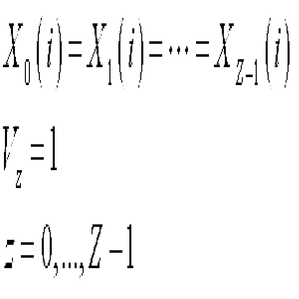
수학식 20은 랭크 1 전송에서 각 안테나 클러스트의 데이터를 나타낸다. Equation 20 shows data of each antenna cluster in rank 1 transmission.
랭크 1 전송에서 모든 안테나 클러스터의 계층 수는 1이며, 동일한 데이터가 전송된다. 귀환데이터로는 Z개 안테나 클러스터를 위한 Z개의 PMI와 1개의 CQI가 요구된다. In rank 1 transmission, the number of layers of all antenna clusters is 1, and the same data is transmitted. The feedback data requires Z PMIs and one CQI for the Z antenna clusters.
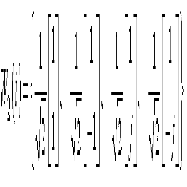
수학식 21은 8Tx 전송에서 4Tx 안테나를 갖는 2개의 안테나 클러스터에 프리코딩 가중치가 적용된 데이터의 예를 나타낸다.Equation 21 shows an example of data to which precoding weights are applied to two antenna clusters having 4Tx antennas in 8Tx transmission.
8Tx 전송에서 4Tx를 갖는 2개의 안테나 클러스터를 고려할 때, 각 안테나 클러스터를 위한 PMI는 안테나 클러스터별로 선택되는데, 두 PMI는 8Tx 랭크 1 전송의 처리량을 최대화할 수 있는 가중치가 선택된다. 처리량은 SNR을 기반으로 계산될 수 있는데, SNR은 수학식 22와 같이 구할 수 있다.Considering two antenna clusters having 4Tx in 8Tx transmission, the PMI for each antenna cluster is selected for each antenna cluster, and the two PMIs are weighted to maximize the throughput of the 8Tx rank 1 transmission. Throughput can be calculated based on SNR, which can be obtained as shown in Equation 22.
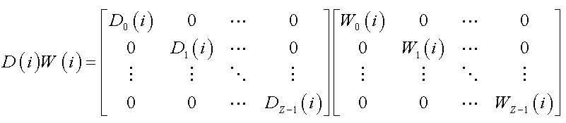
이때, 안테나 클러스터들의 계층 수가 같을 때 프리코딩 가중치 행렬은 다음 수학식과 같이 나타낼 수 있다. In this case, when the number of layers of the antenna clusters is the same, the precoding weight matrix may be expressed as the following equation.
a, b, c 및 d는 프리코딩 가중치 행렬을 다양하게 구성하기 위한 가중치 상수이다. 가중치 상수는 임의의 복소 스칼라(complex scalar)값이 될 수 있다. 프리코딩 연산을 간단히 하기 위하여 가중치 상수는 제한되어 사용될 수 있다. 정해진 가중치 상수에 의해 코드북이 구성될 수 있다. 예를 들어, 가중치 상수는 QPSK의 ±1, ±j 또는 8PSK의 , ±1, ±j가 될 수 있다. 이에 따라, 최종적으로 코드북 W(i)는 QPSK 또는 8PSK의 가중치 상수로 구성될 수 있다. W(i)는 와 같이 구성될 수 있다. 가중치 상수는 전력 정상화(power normalization)되도록 값이 조절될 수 있다. a, b, c, and d are weight constants for variously constructing the precoding weight matrix. The weight constant can be any complex scalar value. In order to simplify the precoding operation, weight constants can be used in a limited way. The codebook may be constructed by a given weight constant. For example, the weight constant can be ± 1, ± j, or 8PSK of QPSK. , ± 1, ± j. Accordingly, finally, the codebook W (i) may be composed of a weight constant of QPSK or 8PSK. W (i) is It can be configured as. The weight constant may be adjusted to be power normalized.
프리코딩 가중치 행렬 중 일부는 동일하게 구성될 수 있다. 예를 들어, W0(i)=W1(i), W2(i)=W3(i)로 구성되거나, W0(i)=W2(i), W1(i)=W3(i)로 구성될 수 있다. Some of the precoding weight matrices may be configured identically. For example, W 0 (i) = W 1 (i), W 2 (i) = W 3 (i), or W 0 (i) = W 2 (i), W 1 (i) = W It may consist of 3 (i).
수학식 24는 a=1, b=1, c=1, d=-1이고 W0(i)=W1(i), W2(i)=W3(i)일 때의 프리코딩 가중치 행렬을 나타낸다. Equation 24 is a precoding weight when a = 1, b = 1, c = 1, d = -1 and W 0 (i) = W 1 (i), W 2 (i) = W 3 (i) Represents a matrix.
수학식 25는 a=1, b=1, c=1, d=-1이고 W0(i)=W2(i), W1(i)=W3(i)일 때의 프리코딩 가중치 행렬을 나타낸다.Equation 25 is a precoding weight when a = 1, b = 1, c = 1, d = -1 and W 0 (i) = W 2 (i), W 1 (i) = W 3 (i) Represents a matrix.
수학식 26은 a=1, b=1, c=j, d=-j이고 W0(i)=W1(i), W2(i)=W3(i)일 때의 프리코딩 가중치 행렬을 나타낸다.Equation 26 is a precoding weight when a = 1, b = 1, c = j, d = -j and W 0 (i) = W 1 (i), W 2 (i) = W 3 (i) Represents a matrix.
수학식 27은 a=1, b=1, c=j, d=-j이고 W0(i)=W2(i), W1(i)=W3(i)일 때의 프리코딩 가중치 행렬을 나타낸다.Equation 27 is a precoding weight when a = 1, b = 1, c = j, d = -j and W 0 (i) = W 2 (i), W 1 (i) = W 3 (i) Represents a matrix.
수학식 28은 a=1, b=j, c=1, d=-j이고 W0(i)=W1(i), W2(i)=W3(i)일 때의 프리코딩 가중치 행렬을 나타낸다.Equation 28 is a precoding weight when a = 1, b = j, c = 1, d = -j and W 0 (i) = W 1 (i), W 2 (i) = W 3 (i) Represents a matrix.
수학식 29는 a=1, b=j, c=1, d=-j이고 W0(i)=W2(i), W1(i)=W3(i)일 때의 프리코딩 가중치 행렬을 나타낸다.Equation 29 is a precoding weight when a = 1, b = j, c = 1, d = -j and W 0 (i) = W 2 (i), W 1 (i) = W 3 (i) Represents a matrix.
일부 프리코딩 가중치 행렬은 복소 결합(complex conjugate)될 수 있다. 수학식 30 내지 33은 복소 결합된 프리코딩 가중치 행렬의 예를 나타낸다. Some precoding weight matrices may be complex conjugated. Equations 30 to 33 show examples of complex combined precoding weight matrices.
복소 결합된 프리코딩 가중치 행렬에는 CDD를 위한 사선 행렬 D(i) 또는 DFT 단일 행렬 U(i)가 적용될 수 있다. 수학식 34 내지 36은 프리코딩 가중치 행렬에 사선 행렬 D(i)가 적용된 예를 나타낸다. An oblique matrix D (i) or a DFT single matrix U (i) for the CDD may be applied to the complex combined precoding weight matrix. Equations 34 to 36 show examples of applying the diagonal matrix D (i) to the precoding weight matrix.
수학식 37은 프리코딩 가중치 행렬에 DFT 단일 행렬이 적용된 예를 나타낸다. Equation 37 shows an example in which a DFT single matrix is applied to a precoding weight matrix.
W2(i)는 임의의 단일 행렬이다. W 2 (i) is any single matrix.
수학식 38은 프리코딩 가중치 행렬에 사선 행렬 D(i) 및 DFT 단일 행렬 U(i)가 적용된 예를 나타낸다. Equation 38 shows an example in which the diagonal matrix D (i) and the DFT single matrix U (i) are applied to the precoding weight matrix.
프리코딩 가중치 행렬 및 임의의 단일 행렬은 수학식 39와 같이 나타낼 수 있다.The precoding weight matrix and any single matrix can be represented by Equation 39.
프리코딩 가중치 행렬은 수학식 40과 같이 표현될 수 있다.The precoding weight matrix may be expressed as Equation 40.
복소 스칼라값의 가중치 상수가 적용되면 프리코딩 가중치 행렬은 수학식 41과 같이 표현될 수 있다. 프리코딩 연산을 간단히 하기 위해 가중치 상수는 제한되어 표현될 수 있다. When the weight constant of the complex scalar value is applied, the precoding weight matrix may be expressed as in Equation 41. In order to simplify the precoding operation, the weight constant may be expressed in a limited manner.
W1(i)은 W0(i)로 강제될 수 있으며, 이에 따라 프리코딩 가중치 행렬은 수학식 42와 같이 표현될 수 있다.W 1 (i) may be forced to W 0 (i), and thus the precoding weight matrix may be expressed as Equation 42.
a=1, b=1이고 W0(i)=W1(i)이면, 프리코딩 가중치 행렬은 수학식 43과 같이 표현될 수 있다. If a = 1, b = 1 and W 0 (i) = W 1 (i), the precoding weight matrix may be expressed as Equation 43.
a=1, b=-1이고 W0(i)=W1(i)이면, 프리코딩 가중치 행렬은 수학식 44와 같이 표현될 수 있다. If a = 1, b = -1 and W 0 (i) = W 1 (i), the precoding weight matrix may be expressed as Equation 44.
a=1, b=j이고 W0(i)=W1(i)이면, 프리코딩 가중치 행렬은 수학식 45와 같이 표현될 수 있다.If a = 1, b = j and W 0 (i) = W 1 (i), the precoding weight matrix may be expressed as Equation 45.
a=1, b=-j이고 W0(i)=W1(i)이면, 프리코딩 가중치 행렬은 수학식 46과 같이 표현될 수 있다.If a = 1, b = -j and W 0 (i) = W 1 (i), the precoding weight matrix may be expressed as Equation 46.
프리코딩 가중치 행렬 및 임의의 단일 행렬은 수학식 47과 같이 나타낼 수 있다.The precoding weight matrix and any single matrix can be represented by Equation 47.
수학식 24 내지 47에서 W0(i) 및 W1(i)은 W0(i)=W1(i)로 강제될 수 있으며, 이에 따라 귀환 정보로 W0(i) 또는 W1(i)을 지시하는 지시자가 사용될 수 있다. 이때, 수학식 39의 프리코딩 가중치 행렬은 수학식 48과 같이 표현될 수 있다.In Equations 24 to 47, W 0 (i) and W 1 (i) may be forced to W 0 (i) = W 1 (i), and thus W 0 (i) or W 1 (i as feedback information. ) Can be used. In this case, the precoding weight matrix of Equation 39 may be expressed as Equation 48.
이상에서와 같이, 기존의 코드북을 활용하여 발전된 시스템의 확장되는 다중안테나를 지원할 수 있으므로 시스템의 복잡도를 줄일 수 있다. 또한, 확장된 다중안테나를 지원하지 못하는 기존 시스템의 단말에 대하여 기존의 코드북을 그대로 사용할 수 있으며 기존 시스템에 대한 역지원성(backward compatibility)을 보장할 수 있다. 단말은 다중안테나 시스템에서 동작하며, 기지국의 복수 개의 송신 안테나 채널을 추정하고, 추정된 채널로부터 서로 다른 복수 개의 안테나를 포함하는 제1 클러스터 및 제2 클러스터에 대한 채널 종속적 프리코딩 행렬 또는 PMI를 기지국으로 귀환하고, 귀환된 프리코딩 행렬 또는 PMI로부터 유도되거나 직접 사용되는 프리코딩 가중치를 이용하여 프리코딩되어 전송되는 데이터를 수신할 수 있다.As described above, since the existing codebook can be used to support the extended multiple antennas of the advanced system, the complexity of the system can be reduced. In addition, the existing codebook can be used as it is for the terminal of the existing system that does not support the extended multi-antenna and can guarantee backward compatibility for the existing system. The UE operates in a multi-antenna system, estimates a plurality of transmit antenna channels of a base station, and performs channel dependent precoding matrix or PMI for a first cluster and a second cluster including a plurality of different antennas from the estimated channel. It is possible to receive data that is precoded and transmitted using a precoding weight derived from the fed back precoding matrix or PMI or directly used.
상술한 모든 기능은 상기 기능을 수행하도록 코딩된 소프트웨어나 프로그램 코드 등에 따른 마이크로프로세서, 제어기, 마이크로제어기, ASIC(Application Specific Integrated Circuit) 등과 같은 프로세서에 의해 수행될 수 있다. 상기 코드의 설계, 개발 및 구현은 본 발명의 설명에 기초하여 당업자에게 자명하다고 할 것이다.All of the above functions may be performed by a processor such as a microprocessor, a controller, a microcontroller, an application specific integrated circuit (ASIC), or the like according to software or program code coded to perform the function. The design, development and implementation of the code will be apparent to those skilled in the art based on the description of the present invention.
이상 본 발명에 대하여 실시예를 참조하여 설명하였지만, 해당 기술 분야의 통상의 지식을 가진 자는 본 발명의 기술적 사상 및 영역으로부터 벗어나지 않는 범위 내에서 본 발명을 다양하게 수정 및 변경시켜 실시할 수 있음을 이해할 수 있을 것이다. 따라서 상술한 실시예에 한정되지 않고, 본 발명은 이하의 특허청구범위의 범위 내의 모든 실시예들을 포함한다고 할 것이다.Although the present invention has been described above with reference to the embodiments, it will be apparent to those skilled in the art that the present invention may be modified and changed in various ways without departing from the spirit and scope of the present invention. I can understand. Therefore, the present invention is not limited to the above-described embodiment, and the present invention will include all embodiments within the scope of the following claims.