WO2010004772A1 - Optical connector and method for assembling optical connector - Google Patents
Optical connector and method for assembling optical connector Download PDFInfo
- Publication number
- WO2010004772A1 WO2010004772A1 PCT/JP2009/050204 JP2009050204W WO2010004772A1 WO 2010004772 A1 WO2010004772 A1 WO 2010004772A1 JP 2009050204 W JP2009050204 W JP 2009050204W WO 2010004772 A1 WO2010004772 A1 WO 2010004772A1
- Authority
- WO
- WIPO (PCT)
- Prior art keywords
- optical fiber
- housing
- optical connector
- fixing
- fixed
- Prior art date
Links
Images


Classifications
-
- G—PHYSICS
- G02—OPTICS
- G02B—OPTICAL ELEMENTS, SYSTEMS OR APPARATUS
- G02B6/00—Light guides; Structural details of arrangements comprising light guides and other optical elements, e.g. couplings
- G02B6/24—Coupling light guides
- G02B6/36—Mechanical coupling means
- G02B6/38—Mechanical coupling means having fibre to fibre mating means
- G02B6/3807—Dismountable connectors, i.e. comprising plugs
- G02B6/3887—Anchoring optical cables to connector housings, e.g. strain relief features
- G02B6/3888—Protection from over-extension or over-compression
-
- G—PHYSICS
- G02—OPTICS
- G02B—OPTICAL ELEMENTS, SYSTEMS OR APPARATUS
- G02B6/00—Light guides; Structural details of arrangements comprising light guides and other optical elements, e.g. couplings
- G02B6/24—Coupling light guides
- G02B6/36—Mechanical coupling means
- G02B6/38—Mechanical coupling means having fibre to fibre mating means
- G02B6/3807—Dismountable connectors, i.e. comprising plugs
- G02B6/3887—Anchoring optical cables to connector housings, e.g. strain relief features
-
- G—PHYSICS
- G02—OPTICS
- G02B—OPTICAL ELEMENTS, SYSTEMS OR APPARATUS
- G02B6/00—Light guides; Structural details of arrangements comprising light guides and other optical elements, e.g. couplings
- G02B6/24—Coupling light guides
- G02B6/36—Mechanical coupling means
- G02B6/38—Mechanical coupling means having fibre to fibre mating means
- G02B6/3801—Permanent connections, i.e. wherein fibres are kept aligned by mechanical means
- G02B6/3806—Semi-permanent connections, i.e. wherein the mechanical means keeping the fibres aligned allow for removal of the fibres
-
- G—PHYSICS
- G02—OPTICS
- G02B—OPTICAL ELEMENTS, SYSTEMS OR APPARATUS
- G02B6/00—Light guides; Structural details of arrangements comprising light guides and other optical elements, e.g. couplings
- G02B6/24—Coupling light guides
- G02B6/36—Mechanical coupling means
- G02B6/38—Mechanical coupling means having fibre to fibre mating means
- G02B6/3807—Dismountable connectors, i.e. comprising plugs
- G02B6/381—Dismountable connectors, i.e. comprising plugs of the ferrule type, e.g. fibre ends embedded in ferrules, connecting a pair of fibres
- G02B6/3818—Dismountable connectors, i.e. comprising plugs of the ferrule type, e.g. fibre ends embedded in ferrules, connecting a pair of fibres of a low-reflection-loss type
- G02B6/3821—Dismountable connectors, i.e. comprising plugs of the ferrule type, e.g. fibre ends embedded in ferrules, connecting a pair of fibres of a low-reflection-loss type with axial spring biasing or loading means
-
- G—PHYSICS
- G02—OPTICS
- G02B—OPTICAL ELEMENTS, SYSTEMS OR APPARATUS
- G02B6/00—Light guides; Structural details of arrangements comprising light guides and other optical elements, e.g. couplings
- G02B6/24—Coupling light guides
- G02B6/36—Mechanical coupling means
- G02B6/38—Mechanical coupling means having fibre to fibre mating means
- G02B6/3807—Dismountable connectors, i.e. comprising plugs
- G02B6/3833—Details of mounting fibres in ferrules; Assembly methods; Manufacture
- G02B6/3846—Details of mounting fibres in ferrules; Assembly methods; Manufacture with fibre stubs
-
- G—PHYSICS
- G02—OPTICS
- G02B—OPTICAL ELEMENTS, SYSTEMS OR APPARATUS
- G02B6/00—Light guides; Structural details of arrangements comprising light guides and other optical elements, e.g. couplings
- G02B6/24—Coupling light guides
- G02B6/36—Mechanical coupling means
- G02B6/38—Mechanical coupling means having fibre to fibre mating means
- G02B6/3807—Dismountable connectors, i.e. comprising plugs
- G02B6/3833—Details of mounting fibres in ferrules; Assembly methods; Manufacture
- G02B6/3855—Details of mounting fibres in ferrules; Assembly methods; Manufacture characterised by the method of anchoring or fixing the fibre within the ferrule
- G02B6/3862—Details of mounting fibres in ferrules; Assembly methods; Manufacture characterised by the method of anchoring or fixing the fibre within the ferrule radially-compressed, longitudinally-split ferrules consisting of a pair of identical matching halves
-
- G—PHYSICS
- G02—OPTICS
- G02B—OPTICAL ELEMENTS, SYSTEMS OR APPARATUS
- G02B6/00—Light guides; Structural details of arrangements comprising light guides and other optical elements, e.g. couplings
- G02B6/24—Coupling light guides
- G02B6/36—Mechanical coupling means
- G02B6/38—Mechanical coupling means having fibre to fibre mating means
- G02B6/3807—Dismountable connectors, i.e. comprising plugs
- G02B6/3873—Connectors using guide surfaces for aligning ferrule ends, e.g. tubes, sleeves, V-grooves, rods, pins, balls
- G02B6/3874—Connectors using guide surfaces for aligning ferrule ends, e.g. tubes, sleeves, V-grooves, rods, pins, balls using tubes, sleeves to align ferrules
- G02B6/3877—Split sleeves
-
- G—PHYSICS
- G02—OPTICS
- G02B—OPTICAL ELEMENTS, SYSTEMS OR APPARATUS
- G02B6/00—Light guides; Structural details of arrangements comprising light guides and other optical elements, e.g. couplings
- G02B6/24—Coupling light guides
- G02B6/36—Mechanical coupling means
- G02B6/38—Mechanical coupling means having fibre to fibre mating means
- G02B6/3807—Dismountable connectors, i.e. comprising plugs
- G02B6/389—Dismountable connectors, i.e. comprising plugs characterised by the method of fastening connecting plugs and sockets, e.g. screw- or nut-lock, snap-in, bayonet type
- G02B6/3893—Push-pull type, e.g. snap-in, push-on
-
- G—PHYSICS
- G02—OPTICS
- G02B—OPTICAL ELEMENTS, SYSTEMS OR APPARATUS
- G02B6/00—Light guides; Structural details of arrangements comprising light guides and other optical elements, e.g. couplings
- G02B6/24—Coupling light guides
- G02B6/36—Mechanical coupling means
- G02B6/38—Mechanical coupling means having fibre to fibre mating means
- G02B6/3807—Dismountable connectors, i.e. comprising plugs
- G02B6/3898—Tools, e.g. handheld; Tuning wrenches; Jigs used with connectors, e.g. for extracting, removing or inserting in a panel, for engaging or coupling connectors, for assembling or disassembling components within the connector, for applying clips to hold two connectors together or for crimping
Abstract
Disclosed is an optical connector to be assembled to a terminal of an optical fiber cable having a tensile strength body. The optical connector is provided with a housing, a ferrule arranged in the housing, and a fixing cap to be attached to the housing. The housing is provided with a fixing section having a screw section formed on the outer circumference surface. The fixing cap can be fixed with a screw in a state where the tensile strength body taken out from the optical fiber cable terminal is sandwiched between the housing and the fixing cap.
Description
本発明は、光コネクタ、特に、工場外の現場で専用工具を用いることなく組み立てることができる現場組立型の光コネクタおよび光コネクタの組立方法に関する。
本願は、2008年7月10日に日本に出願された特願2008-180694号に基づき優先権を主張し、その内容をここに援用する。 The present invention relates to an optical connector, and more particularly, to an on-site assembly type optical connector that can be assembled without using a dedicated tool at a site outside the factory, and an optical connector assembling method.
This application claims priority based on Japanese Patent Application No. 2008-180694 for which it applied to Japan on July 10, 2008, and uses the content here.
抗張力繊維を有する光ファイバケーブル(例えば光コード)の先端に組み立てられる光コネクタとしては、抗張力繊維を引き留める構造を有するものがある。
この引き留め構造としては、例えば、カシメ部材によって抗張力繊維をストップリングにカシメ固定する構造がある(特許文献1、2を参照)。
カシメ固定構造では、専用工具によってカシメ部材の取り付けが行われる。
特開平10-206687号公報
米国特許第6206581号明細書
As an optical connector assembled at the tip of an optical fiber cable (for example, an optical cord) having a tensile strength fiber, there is one having a structure for retaining the tensile strength fiber.
As this retaining structure, for example, there is a structure in which a tensile strength fiber is caulked and fixed to a stop ring by a caulking member (seePatent Documents 1 and 2).
In the caulking fixing structure, the caulking member is attached by a dedicated tool.
Japanese Patent Laid-Open No. 10-206687 US Pat. No. 6,206,581
この引き留め構造としては、例えば、カシメ部材によって抗張力繊維をストップリングにカシメ固定する構造がある(特許文献1、2を参照)。
カシメ固定構造では、専用工具によってカシメ部材の取り付けが行われる。
As this retaining structure, for example, there is a structure in which a tensile strength fiber is caulked and fixed to a stop ring by a caulking member (see
In the caulking fixing structure, the caulking member is attached by a dedicated tool.
しかしながら、上記光コネクタでは、専用工具が必要となるため組み立て作業に手間がかかり、作業を容易にすることが要望されていた。
また、汎用のカシメ固定構造では、一度取り付けたカシメ部材の取り外しは難しいため、何らかの原因によって抗張力体の固定が不十分となった場合には、カシメ部材を取り付けた部分の光ファイバを切除してカシメ部分を解体し、新たな端末に新たなカシメ部材の取り付け作業を行う必要がある。このため、光コネクタの組み立ての歩留まりの点で問題があった。
本発明は、上記事情に鑑みてなされたもので、組み立てが容易であり、しかも組み立ての歩留まりの点で優れた光コネクタおよび光コネクタの組立方法を提供することを目的とする。 However, since the optical connector requires a dedicated tool, it takes time to assemble, and it has been desired to facilitate the work.
In addition, with a general caulking fixing structure, it is difficult to remove the caulking member once attached. Therefore, if the tension member is insufficiently fixed for some reason, cut off the optical fiber at the part where the caulking member is attached. It is necessary to dismantle the caulking portion and perform a new caulking member mounting operation on a new terminal. For this reason, there was a problem in terms of assembly yield of the optical connector.
The present invention has been made in view of the above circumstances, and an object thereof is to provide an optical connector and an optical connector assembling method that are easy to assemble and that are excellent in terms of assembly yield.
本発明の光コネクタは、光ファイバと、この光ファイバの長手方向に沿って延在する抗張力体とを一体化した光ファイバケーブルの端末に組み立てられる光コネクタであって、ハウジングと、このハウジング内に設けられたフェルールと、前記ハウジングに装着される固定キャップとを備え、前記ハウジングが、外周面にネジ部が形成された固定部を有し、前記固定キャップが、前記光ファイバケーブル端末から引き出された前記抗張力体を前記ハウジングとの間に挟んだ状態で、前記固定部にネジ止め固定可能である。
本発明の光コネクタは、前記フェルールに内挿された内蔵光ファイバが、前記光ファイバケーブル端末に口出しした前記光ファイバに接続可能である構成としてよい。
本発明の光コネクタは、前記固定部の外周面に、前記抗張力体を収容可能な1または複数の溝部が形成されている構成としてよい。
本発明の光コネクタは、前記溝部が複数形成され、これら溝部が、前記光ファイバの挿通方向に対し互いに回転対称となる位置に形成されている構成としてよい。
本発明の光コネクタは、前記固定部の外周面に、全周にわたって前記ネジ部が形成されている構成としてよい。
本発明の光コネクタは、前記ハウジングに、前記固定キャップのネジ止めに先だって前記抗張力体を前記ハウジングに引き留め可能な引留リングが装着され、この引留リングが、前記ハウジングとの間に前記抗張力体を挟み込んで引き留め可能である構成としてよい。
本発明の光コネクタは、前記ハウジングが、前記固定部より細径であって前記固定部から後方に延出する延出筒部を有し、前記引留リングが、前記延出筒部との間に前記抗張力体を挟み込んで引き留め可能である構成としてよい。
本発明の光コネクタは、前記光ファイバケーブルの外被に保護チューブが固定され、この保護チューブが、筒状のチューブ本体と、このチューブ本体から外方に突出する係止突起部を有し、この係止突起部は、前記固定キャップ内面に形成された係止段部に係止して前記保護チューブの後方移動を阻止するように形成されている構成としてよい。
本発明の光コネクタは、前記抗張力体が、複数の集合体に分けた状態で前記ハウジングの周方向に離間した位置に固定されている構成としてよい。
本発明の光コネクタは、光ファイバと、この光ファイバの長手方向に沿って延在する抗張力体とを一体化した光ファイバケーブルの端末に組み立てられる光コネクタであって、コネクタ本体の後端に、外周面にネジ部が形成された固定部を有し、前記固定部には、固定キャップがネジ止め固定可能であり、前記固定キャップは、前記光ファイバケーブル端末から引き出された前記抗張力体を前記コネクタ本体との間に挟んだ状態で、前記固定部にネジ止め固定可能である構成としてよい。 An optical connector of the present invention is an optical connector assembled at an end of an optical fiber cable in which an optical fiber and a tensile body extending along the longitudinal direction of the optical fiber are integrated. A ferrule provided on the housing and a fixing cap attached to the housing, the housing having a fixing portion having a threaded portion formed on an outer peripheral surface thereof, and the fixing cap being pulled out from the optical fiber cable end. The tension member can be fixed with screws to the fixing portion in a state where the tensile strength member is sandwiched between the housing and the housing.
The optical connector of the present invention may be configured such that a built-in optical fiber inserted into the ferrule can be connected to the optical fiber led out to the optical fiber cable terminal.
The optical connector of the present invention may have a configuration in which one or a plurality of grooves that can accommodate the strength member are formed on the outer peripheral surface of the fixing portion.
The optical connector of the present invention may be configured such that a plurality of the groove portions are formed, and the groove portions are formed at positions that are rotationally symmetric with respect to the insertion direction of the optical fiber.
The optical connector of this invention is good also as a structure by which the said thread part is formed in the outer peripheral surface of the said fixing | fixed part over the perimeter.
In the optical connector according to the present invention, a retaining ring capable of retaining the tensile strength body on the housing is attached to the housing prior to screwing the fixing cap, and the retaining ring places the tensile strength body between the housing and the housing. It is good also as a structure which can be pinched and can be kept.
In the optical connector of the present invention, the housing has an extended cylindrical portion that is smaller in diameter than the fixed portion and extends rearward from the fixed portion, and the retaining ring is between the extended cylindrical portion and the extended cylindrical portion. It is good also as a structure which can pinch and hold | maintain the said tension body.
In the optical connector of the present invention, a protective tube is fixed to the jacket of the optical fiber cable, and the protective tube has a tubular tube main body and a locking protrusion protruding outward from the tube main body, The locking projection may be configured to be locked to a locking step formed on the inner surface of the fixed cap so as to prevent backward movement of the protective tube.
The optical connector of the present invention may be configured such that the strength members are fixed at positions separated in the circumferential direction of the housing in a state where the strength members are divided into a plurality of aggregates.
The optical connector of the present invention is an optical connector assembled at the end of an optical fiber cable in which an optical fiber and a tensile body extending along the longitudinal direction of the optical fiber are integrated. A fixing portion having a threaded portion formed on an outer peripheral surface, and a fixing cap can be fixed to the fixing portion by screwing, and the fixing cap is provided with the tensile body drawn from the end of the optical fiber cable. It is good also as a structure which can be screwed and fixed to the said fixing | fixed part in the state pinched | interposed between the said connector main bodies.
本発明の光コネクタの組立方法は、光ファイバと、この光ファイバの長手方向に沿って延在する抗張力体とを一体化した光ファイバケーブルの端末に、光コネクタを組み立てる方法であって、前記光コネクタが、ハウジングと、このハウジング内に設けられたフェルールと、前記ハウジングに装着される固定キャップとを備え、前記ハウジングが、外周面にネジ部が形成された固定部を有し、前記固定キャップが、前記固定部にネジ止め固定可能とされ、前記フェルールに内挿された内蔵光ファイバに、前記光ファイバケーブル端末に口出しした前記光ファイバを突き合わせ接続し、その後、前記光ファイバケーブル端末から引き出された前記抗張力体を前記ハウジングとの間に挟んだ状態で、前記固定キャップを前記固定部にネジ止め固定する方法である。
本発明の光コネクタの組立方法では、前記固定キャップのネジ止めに先だって、引留リングによって、前記抗張力体を前記ハウジングとの間に挟み込んで引き留めることができる。
本発明の光コネクタの組立方法では、前記固定キャップのネジ止めに先だって、前記抗張力体を、複数の集合体に分けた状態で前記ハウジングの周方向に離間した位置に配置することができる。
本発明の光コネクタの組立方法は、光ファイバと、この光ファイバの長手方向に沿って延在する抗張力体とを一体化した光ファイバケーブルの端末に、光コネクタを組み立てる方法であって、前記光コネクタが、コネクタ本体の後端に、外周面にネジ部が形成された固定部を有し、前記固定部に、固定キャップがネジ止め固定可能とされ、前記光ファイバケーブル端末から引き出された前記抗張力体を前記コネクタ本体との間に挟んだ状態で、前記固定キャップを前記固定部にネジ止め固定する方法である。
本発明の光コネクタの組立方法では、前記固定キャップのネジ止めに先だって、前記抗張力体を、複数の集合体に分けた状態で前記ハウジングの周方向に離間した位置に配置することができる。 An optical connector assembling method of the present invention is a method for assembling an optical connector at an end of an optical fiber cable in which an optical fiber and a tensile body extending along the longitudinal direction of the optical fiber are integrated. The optical connector includes a housing, a ferrule provided in the housing, and a fixing cap attached to the housing, and the housing has a fixing portion in which a screw portion is formed on an outer peripheral surface, and the fixing The cap can be fixed to the fixing portion with a screw, and the built-in optical fiber inserted into the ferrule is butt-connected to the optical fiber cable terminal, and then from the optical fiber cable terminal The fixing cap is fixed to the fixing portion with a screw in a state in which the pulled strength member is sandwiched between the housing and the housing. It is that way.
In the method of assembling the optical connector of the present invention, prior to screwing the fixing cap, the tension member can be sandwiched between the housing and retained by a retaining ring.
In the optical connector assembling method of the present invention, prior to screwing the fixing cap, the strength members can be arranged at positions separated in the circumferential direction of the housing in a state of being divided into a plurality of aggregates.
An optical connector assembling method of the present invention is a method for assembling an optical connector at an end of an optical fiber cable in which an optical fiber and a tensile body extending along the longitudinal direction of the optical fiber are integrated. The optical connector has a fixing portion formed with a screw portion on the outer peripheral surface at the rear end of the connector main body, and a fixing cap can be fixed to the fixing portion with a screw, and is pulled out from the optical fiber cable terminal. The fixing cap is screwed and fixed to the fixing portion in a state where the strength member is sandwiched between the connector body and the main body.
In the optical connector assembling method of the present invention, prior to screwing the fixing cap, the strength members can be arranged at positions separated in the circumferential direction of the housing in a state of being divided into a plurality of aggregates.
本発明の光コネクタは、固定キャップを固定部にネジ止めすることによって抗張力体を固定する構造を有する。汎用のカシメ固定構造では専用工具が必要となるが、本発明ではネジ止めを採用するため、専用工具は不要となり、組み立てが容易になる。
また、ネジ止め固定を採用するため、抗張力体を強固にハウジングに固定し、光ファイバケーブルとの接続部分に十分な強度を与えることができる。
また、本発明の光コネクタでは、固定構造における部品点数が少なく構造が簡略であるため、組み立て工程数を削減することができる。構造が簡略であるため、光コネクタの小型化、すなわち全長を短くすることも可能となる。
汎用のカシメ固定構造では、一度取り付けたカシメ部材の取り外しは難しいため、誤操作などにより抗張力体の固定が不十分となった場合には、カシメ部材を取り付けた部分の光ファイバを切除して、新たな端末にカシメ部材の取り付け作業を行う必要がある。
これに対し、本発明の光コネクタでは、ネジ止めを採用するので、誤操作などにより抗張力体の固定が不十分となった場合は、固定キャップを外して、固定キャップの装着をやり直すことができる。従って、光コネクタの組み立ての歩留まりが良くなる。 The optical connector of the present invention has a structure in which the tensile strength body is fixed by screwing the fixing cap to the fixing portion. The general-purpose caulking fixing structure requires a dedicated tool. However, since the present invention employs screwing, the dedicated tool is not required and assembly is facilitated.
In addition, since the screw fixing is employed, the strength member can be firmly fixed to the housing, and sufficient strength can be given to the connection portion with the optical fiber cable.
Moreover, in the optical connector of the present invention, the number of parts in the fixed structure is small and the structure is simple, so the number of assembly steps can be reduced. Since the structure is simple, the optical connector can be downsized, that is, the entire length can be shortened.
With the general caulking fixing structure, it is difficult to remove the caulking member once attached. If the tension member is insufficiently fixed due to misoperation, etc., cut off the optical fiber at the part where the caulking member is attached, It is necessary to perform a caulking member mounting operation on a simple terminal.
On the other hand, since the optical connector of the present invention employs screwing, when the strength member is not sufficiently fixed due to an erroneous operation or the like, the fixing cap can be removed and the fixing cap can be attached again. Therefore, the assembly yield of the optical connector is improved.
1、41 光コネクタ
2 ハウジング
5、42 固定キャップ
6 引留リング
14 固定部
15 延出筒部
16 ネジ部
25 溝部
31 光ファイバケーブル
32 光ファイバ
33 抗張力体
34 外被
43 保護チューブ
51 係止段部
54 チューブ本体
55 フランジ部(係止突起) DESCRIPTION OF SYMBOLS 1, 41 Optical connector 2 Housing 5, 42 Fixing cap 6 Retention ring 14 Fixing part 15 Extension cylinder part 16 Screw part 25 Groove part 31 Optical fiber cable 32 Optical fiber 33 Strength body 34 Outer cover 43 Protection tube 51 Locking step part 54 Tube body 55 Flange (locking protrusion)
2 ハウジング
5、42 固定キャップ
6 引留リング
14 固定部
15 延出筒部
16 ネジ部
25 溝部
31 光ファイバケーブル
32 光ファイバ
33 抗張力体
34 外被
43 保護チューブ
51 係止段部
54 チューブ本体
55 フランジ部(係止突起) DESCRIPTION OF
以下、本発明の第1の実施形態を、図面を参照して説明する。
図1は、本発明の第1の実施形態である光コネクタ1を示す断面図である。図1は、図2におけるA-A断面矢視図である。図2は、光コネクタ1の外観を示す斜視図である。図3は、光コネクタ1の要部を拡大した図であって、図2におけるA-A断面矢視図である。図4は、光コネクタ1の要部を拡大した図であって、図2におけるB-B断面矢視図である。図5は、光コネクタ1のストップリング本体12aを後方から見た図である。図6は、ストップリング本体12aの固定部14を示す斜視図である。図7および図8は、プラグフレーム11およびクランプ部22の断面図である。 DESCRIPTION OF EXEMPLARY EMBODIMENTS Hereinafter, a first embodiment of the invention will be described with reference to the drawings.
FIG. 1 is a sectional view showing anoptical connector 1 according to the first embodiment of the present invention. 1 is a cross-sectional view taken along line AA in FIG. FIG. 2 is a perspective view showing the appearance of the optical connector 1. FIG. 3 is an enlarged view of a main part of the optical connector 1, and is a cross-sectional view taken along the line AA in FIG. 4 is an enlarged view of a main part of the optical connector 1, and is a cross-sectional view taken along the line BB in FIG. FIG. 5 is a view of the stop ring body 12a of the optical connector 1 as viewed from the rear. FIG. 6 is a perspective view showing the fixing portion 14 of the stop ring body 12a. 7 and 8 are cross-sectional views of the plug frame 11 and the clamp portion 22.
図1は、本発明の第1の実施形態である光コネクタ1を示す断面図である。図1は、図2におけるA-A断面矢視図である。図2は、光コネクタ1の外観を示す斜視図である。図3は、光コネクタ1の要部を拡大した図であって、図2におけるA-A断面矢視図である。図4は、光コネクタ1の要部を拡大した図であって、図2におけるB-B断面矢視図である。図5は、光コネクタ1のストップリング本体12aを後方から見た図である。図6は、ストップリング本体12aの固定部14を示す斜視図である。図7および図8は、プラグフレーム11およびクランプ部22の断面図である。 DESCRIPTION OF EXEMPLARY EMBODIMENTS Hereinafter, a first embodiment of the invention will be described with reference to the drawings.
FIG. 1 is a sectional view showing an
図1および図2に示すように、光コネクタ1は、光ファイバケーブル31の端末に組み立てられている。
光ファイバケーブル31は、光ファイバ心線等の光ファイバ32と、光ファイバ32の長手方向に沿って延在する抗張力体33とが、ポリエチレン等の樹脂からなる外被34内に収容された構造のもの(例えば光ファイバコード)を例示できる。
抗張力体33としては、アラミド繊維が好適に用いられるが、ガラス繊維、炭素繊維なども使用できる。
以下の説明において、図1における左方、すなわち光ファイバケーブル31の先端方向を「前方」といい、右方を「後方」ということがある。 As shown in FIGS. 1 and 2, theoptical connector 1 is assembled at the end of an optical fiber cable 31.
Theoptical fiber cable 31 has a structure in which an optical fiber 32 such as an optical fiber core and a tensile body 33 extending in the longitudinal direction of the optical fiber 32 are accommodated in an outer jacket 34 made of a resin such as polyethylene. (For example, an optical fiber cord).
As thetensile body 33, an aramid fiber is preferably used, but a glass fiber, a carbon fiber, or the like can also be used.
In the following description, the left side in FIG. 1, that is, the tip direction of theoptical fiber cable 31 may be referred to as “front”, and the right side may be referred to as “rear”.
光ファイバケーブル31は、光ファイバ心線等の光ファイバ32と、光ファイバ32の長手方向に沿って延在する抗張力体33とが、ポリエチレン等の樹脂からなる外被34内に収容された構造のもの(例えば光ファイバコード)を例示できる。
抗張力体33としては、アラミド繊維が好適に用いられるが、ガラス繊維、炭素繊維なども使用できる。
以下の説明において、図1における左方、すなわち光ファイバケーブル31の先端方向を「前方」といい、右方を「後方」ということがある。 As shown in FIGS. 1 and 2, the
The
As the
In the following description, the left side in FIG. 1, that is, the tip direction of the
光コネクタ1は、ハウジング2と、ハウジング2内に設けられたクランプ部付きフェルール3と、クランプ部付きフェルール3を前方に付勢するスプリング4(付勢手段)と、ハウジング2に装着される固定キャップ5と、引留リング6とを備えている。
ハウジング2は、スリーブ状のプラグフレーム11と、プラグフレーム11の後端に嵌合して取付けられるキャップ状のストップリング12とからなる。
なお、本実施形態では、固定キャップ5が装着される本体部分(ハウジング2、クランプ部付きフェルール3、スプリング4)を「コネクタ本体」ということがある。 Theoptical connector 1 includes a housing 2, a ferrule 3 with a clamp portion provided in the housing 2, a spring 4 (biasing means) that urges the ferrule 3 with a clamp portion forward, and a fixing that is attached to the housing 2. A cap 5 and a retaining ring 6 are provided.
Thehousing 2 includes a sleeve-like plug frame 11 and a cap-like stop ring 12 fitted and attached to the rear end of the plug frame 11.
In the present embodiment, the main body portion (thehousing 2, the ferrule 3 with a clamp portion, and the spring 4) to which the fixing cap 5 is attached may be referred to as a “connector main body”.
ハウジング2は、スリーブ状のプラグフレーム11と、プラグフレーム11の後端に嵌合して取付けられるキャップ状のストップリング12とからなる。
なお、本実施形態では、固定キャップ5が装着される本体部分(ハウジング2、クランプ部付きフェルール3、スプリング4)を「コネクタ本体」ということがある。 The
The
In the present embodiment, the main body portion (the
図2に示すように、プラグフレーム11は、スリーブ状のフレーム本体11aと、フレーム本体11aの前端部の側面から、フレーム本体11aの後端側に斜めに傾斜して立ち上げられた弾性片11bとを備えている。
ストップリング12は、スリーブ状のストップリング本体12aと、ストップリング本体12aの側部から、ストップリング本体12aに嵌合されるプラグフレーム11側に斜めに傾斜して立ち上げられた弾性片12bとを備えている。
フレーム本体11aとストップリング本体12aはハウジング本体2aであり、弾性片11b、12bはラッチ2bである。
弾性片11b、12bは、突出先端が重なるように形成されており、弾性片12bをハウジング本体2aに向けて弾性変形させると、プラグフレーム11の弾性片11bは押圧されて、ハウジング本体2aに向けて弾性変形される。 As shown in FIG. 2, theplug frame 11 includes a sleeve-shaped frame main body 11a and an elastic piece 11b raised obliquely from the side surface of the front end portion of the frame main body 11a toward the rear end side of the frame main body 11a. And.
Thestop ring 12 includes a sleeve-like stop ring main body 12a, and an elastic piece 12b raised obliquely from the side of the stop ring main body 12a toward the plug frame 11 fitted to the stop ring main body 12a. It has.
The framemain body 11a and the stop ring main body 12a are the housing main body 2a, and the elastic pieces 11b and 12b are the latches 2b.
The elastic pieces 11b and 12b are formed so that the protruding tips overlap each other. When the elastic piece 12b is elastically deformed toward the housing main body 2a, the elastic piece 11b of the plug frame 11 is pressed toward the housing main body 2a. And elastically deformed.
ストップリング12は、スリーブ状のストップリング本体12aと、ストップリング本体12aの側部から、ストップリング本体12aに嵌合されるプラグフレーム11側に斜めに傾斜して立ち上げられた弾性片12bとを備えている。
フレーム本体11aとストップリング本体12aはハウジング本体2aであり、弾性片11b、12bはラッチ2bである。
弾性片11b、12bは、突出先端が重なるように形成されており、弾性片12bをハウジング本体2aに向けて弾性変形させると、プラグフレーム11の弾性片11bは押圧されて、ハウジング本体2aに向けて弾性変形される。 As shown in FIG. 2, the
The
The frame
The
フレーム本体11aに形成された係止爪11cを、ストップリング本体12aの係止窓12cに入り込ませて嵌合させることによって、プラグフレーム11とストップリング12は、一体化されて組み立てられる。
The plug claw 11 and the stop ring 12 are integrated and assembled by inserting and engaging the engaging claws 11c formed on the frame main body 11a into the engaging window 12c of the stop ring main body 12a.
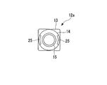
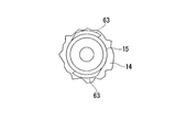
図3および図4に示すように、ストップリング本体12aは、角筒状の基部13と、基部13の後端部から後方に延出する固定部14と、固定部14の後端部から後方に延出する延出筒部15とを有する。
固定部14は、円筒状の筒部14aと、筒部14aの後端から内方に延出する端壁部14bとを有する。
筒部14aの外周面には、ネジ部16が形成されている(図4参照)。
端壁部14bの外面(後面)は、光ファイバ挿通方向(前後方向)に対しほぼ垂直に形成されている。端壁部14bには、光ファイバ32が挿通する挿通孔14cが形成されている。
延出筒部15は、固定部14より細径、すなわち外径が小さい円筒状とされ、その内部に光ファイバ32が挿通可能である。 As shown in FIGS. 3 and 4, thestop ring body 12 a includes a rectangular tube-shaped base portion 13, a fixing portion 14 that extends rearward from the rear end portion of the base portion 13, and a rear portion from the rear end portion of the fixing portion 14. And an extending cylinder portion 15 extending in the direction.
The fixedportion 14 includes a cylindrical tube portion 14a and an end wall portion 14b extending inward from the rear end of the tube portion 14a.
Ascrew portion 16 is formed on the outer peripheral surface of the cylindrical portion 14a (see FIG. 4).
The outer surface (rear surface) of theend wall portion 14b is formed substantially perpendicular to the optical fiber insertion direction (front-rear direction). An insertion hole 14c through which the optical fiber 32 is inserted is formed in the end wall portion 14b.
The extendingcylinder portion 15 has a smaller diameter than the fixed portion 14, that is, a cylindrical shape having a smaller outer diameter, and the optical fiber 32 can be inserted therethrough.
固定部14は、円筒状の筒部14aと、筒部14aの後端から内方に延出する端壁部14bとを有する。
筒部14aの外周面には、ネジ部16が形成されている(図4参照)。
端壁部14bの外面(後面)は、光ファイバ挿通方向(前後方向)に対しほぼ垂直に形成されている。端壁部14bには、光ファイバ32が挿通する挿通孔14cが形成されている。
延出筒部15は、固定部14より細径、すなわち外径が小さい円筒状とされ、その内部に光ファイバ32が挿通可能である。 As shown in FIGS. 3 and 4, the
The fixed
A
The outer surface (rear surface) of the
The extending
図3、図5および図6に示すように、固定部14の外周面には、光ファイバ挿通方向(前後方向)に沿う、ネジが形成されていない溝部25が形成されている。
溝部25は、抗張力体33を収容可能に幅に形成され、固定部14の全長さ方向にわたって形成されている。図示例では、溝部25は断面略扇形に形成され、長さ方向および周方向とも一定深さとなっている。
図示例では、光ファイバ挿通方向に対し互いに回転対称となる位置に2つの溝部25が形成されている。
溝部25が回転対称位置にあるため、ハウジング2に対する抗張力体33の固定強度には周方向の偏りが生じにくい。
なお、溝部の数は、図示例に限らず、1または3以上であってもよい。 As shown in FIGS. 3, 5, and 6, the outer peripheral surface of the fixingportion 14 is formed with a groove portion 25 in which no screw is formed along the optical fiber insertion direction (front-rear direction).
Thegroove portion 25 is formed in a width that can accommodate the strength member 33 and is formed over the entire length of the fixed portion 14. In the example of illustration, the groove part 25 is formed in the cross-sectional substantially sector shape, and is the fixed depth in the length direction and the circumferential direction.
In the illustrated example, twogroove portions 25 are formed at positions that are rotationally symmetric with respect to the optical fiber insertion direction.
Since thegroove portion 25 is in the rotationally symmetric position, the fixing strength of the strength member 33 with respect to the housing 2 is less likely to cause a circumferential deviation.
The number of grooves is not limited to the illustrated example, and may be 1 or 3 or more.
溝部25は、抗張力体33を収容可能に幅に形成され、固定部14の全長さ方向にわたって形成されている。図示例では、溝部25は断面略扇形に形成され、長さ方向および周方向とも一定深さとなっている。
図示例では、光ファイバ挿通方向に対し互いに回転対称となる位置に2つの溝部25が形成されている。
溝部25が回転対称位置にあるため、ハウジング2に対する抗張力体33の固定強度には周方向の偏りが生じにくい。
なお、溝部の数は、図示例に限らず、1または3以上であってもよい。 As shown in FIGS. 3, 5, and 6, the outer peripheral surface of the fixing
The
In the illustrated example, two
Since the
The number of grooves is not limited to the illustrated example, and may be 1 or 3 or more.
図3および図4に示すように、固定キャップ5は、固定部14に装着される装着部17と、装着部17の後端部から後方に延出する接続筒部18とを有する。
装着部17は円筒状の筒部17aと、筒部17aの後端から内方に延出する端壁部17bとを有する。端壁部17bには、光ファイバ32が挿通する挿通孔17cが形成されている。
筒部17aの内面には、固定部14のネジ部16に螺合するネジ部19が形成されている。
端壁部17bの内周縁部の内面(前面)には、引留リング6が配置される環状のリング用凹部20が形成されている。 As shown in FIGS. 3 and 4, the fixingcap 5 includes a mounting portion 17 that is mounted on the fixing portion 14, and a connecting tube portion 18 that extends rearward from the rear end portion of the mounting portion 17.
The mountingportion 17 includes a cylindrical tube portion 17a and an end wall portion 17b extending inward from the rear end of the tube portion 17a. An insertion hole 17c through which the optical fiber 32 is inserted is formed in the end wall portion 17b.
Ascrew portion 19 that is screwed into the screw portion 16 of the fixing portion 14 is formed on the inner surface of the cylindrical portion 17a.
Anannular ring recess 20 in which the retaining ring 6 is disposed is formed on the inner surface (front surface) of the inner peripheral edge of the end wall portion 17b.
装着部17は円筒状の筒部17aと、筒部17aの後端から内方に延出する端壁部17bとを有する。端壁部17bには、光ファイバ32が挿通する挿通孔17cが形成されている。
筒部17aの内面には、固定部14のネジ部16に螺合するネジ部19が形成されている。
端壁部17bの内周縁部の内面(前面)には、引留リング6が配置される環状のリング用凹部20が形成されている。 As shown in FIGS. 3 and 4, the fixing
The mounting
A
An
図3および図4に示すように、固定キャップ5は、光ファイバケーブル31の端末から引き出された抗張力体33をストップリング本体12aとの間に挟んで、固定部14にネジ止め固定可能である。
すなわち、固定キャップ5は、筒部17a内面のネジ部19を、固定部14のネジ部16にネジ嵌合させることによって、固定部14に固定することができる。 As shown in FIGS. 3 and 4, the fixingcap 5 can be fixed to the fixing portion 14 with screws by sandwiching the strength member 33 drawn from the end of the optical fiber cable 31 with the stop ring body 12 a. .
In other words, the fixingcap 5 can be fixed to the fixing portion 14 by screwing the screw portion 19 on the inner surface of the cylindrical portion 17 a with the screw portion 16 of the fixing portion 14.
すなわち、固定キャップ5は、筒部17a内面のネジ部19を、固定部14のネジ部16にネジ嵌合させることによって、固定部14に固定することができる。 As shown in FIGS. 3 and 4, the fixing
In other words, the fixing
引留リング6は、光ファイバケーブル31端末から引き出された抗張力体33をハウジング2に引き留めるものであり、延出筒部15を囲んで設けられて延出筒部15との間に抗張力体33を挟み込んで引き留めるように構成されている。
引留リング6は、樹脂などからなる弾性体で構成し、その弾性力によって延出筒部15との間に抗張力体33を挟み込んで引き留めることができる構成が好ましい。
図示例では、引留リング6は断面円形とされ、固定キャップ5のリング用凹部20に設置され、固定部14の端壁部14bの外面および延出筒部15の外面に対面している。
引留リング6は、端壁部14bおよび延出筒部15との間に、抗張力体33を挟み込むことができるように構成することができる。 The retainingring 6 holds the tensile body 33 pulled out from the end of the optical fiber cable 31 to the housing 2, is provided so as to surround the extended cylinder part 15, and the tensile body 33 is interposed between the extended cylinder part 15. It is configured to be pinched and retained.
The retainingring 6 is preferably composed of an elastic body made of resin or the like, and can be held by holding the tensile body 33 between the extension cylinder portion 15 and its elastic force.
In the illustrated example, the retainingring 6 has a circular cross section, is installed in the ring recess 20 of the fixing cap 5, and faces the outer surface of the end wall portion 14 b of the fixing portion 14 and the outer surface of the extending cylinder portion 15.
The retainingring 6 can be configured such that the strength member 33 can be sandwiched between the end wall portion 14 b and the extended tube portion 15.
引留リング6は、樹脂などからなる弾性体で構成し、その弾性力によって延出筒部15との間に抗張力体33を挟み込んで引き留めることができる構成が好ましい。
図示例では、引留リング6は断面円形とされ、固定キャップ5のリング用凹部20に設置され、固定部14の端壁部14bの外面および延出筒部15の外面に対面している。
引留リング6は、端壁部14bおよび延出筒部15との間に、抗張力体33を挟み込むことができるように構成することができる。 The retaining
The retaining
In the illustrated example, the retaining
The retaining
図1、図7および図8に示すように、クランプ部付きフェルール3は、フェルール21と、フェルール21の後端側(接続端面21aとは反対側)に組み立てられたクランプ部22とを備えている。
フェルール21には、裸光ファイバなどの内蔵光ファイバ10が内挿固定されている。以下、内蔵光ファイバ10をフェルール側光ファイバ10ということがある。
フェルール側光ファイバ10はフェルール21後端から突出されており、突出部分である突出部10aは、クランプ部22の一対の素子22a、22bの間に挿入されている。 As shown in FIGS. 1, 7 and 8, theferrule 3 with a clamp portion includes a ferrule 21 and a clamp portion 22 assembled on the rear end side of the ferrule 21 (the side opposite to the connection end surface 21 a). Yes.
A built-inoptical fiber 10 such as a bare optical fiber is inserted and fixed to the ferrule 21. Hereinafter, the built-in optical fiber 10 may be referred to as a ferrule side optical fiber 10.
The ferrule sideoptical fiber 10 protrudes from the rear end of the ferrule 21, and the protruding portion 10 a that is a protruding portion is inserted between the pair of elements 22 a and 22 b of the clamp portion 22.
フェルール21には、裸光ファイバなどの内蔵光ファイバ10が内挿固定されている。以下、内蔵光ファイバ10をフェルール側光ファイバ10ということがある。
フェルール側光ファイバ10はフェルール21後端から突出されており、突出部分である突出部10aは、クランプ部22の一対の素子22a、22bの間に挿入されている。 As shown in FIGS. 1, 7 and 8, the
A built-in
The ferrule side
クランプ部22は、フェルール21のフランジ部21bから延びる延出部22a(以下、素子22aともいう)と、これに対向する素子22bとを、断面C形のスリーブ状のバネ23の内側に収容した構造になっている。
素子22bは、前後に並ぶ2つの蓋側素子22c、22dからなる。
素子22a、22bのうち一方または両方には、光ファイバ10と光ファイバ32を位置決めする調心溝22eが形成される。 Theclamp part 22 accommodates an extension part 22a (hereinafter also referred to as an element 22a) extending from the flange part 21b of the ferrule 21 and an element 22b facing the extension part 22a inside a sleeve-like spring 23 having a C-shaped cross section. It has a structure.
Theelement 22b includes two lid side elements 22c and 22d arranged in the front and rear direction.
Analignment groove 22e for positioning the optical fiber 10 and the optical fiber 32 is formed in one or both of the elements 22a and 22b.
素子22bは、前後に並ぶ2つの蓋側素子22c、22dからなる。
素子22a、22bのうち一方または両方には、光ファイバ10と光ファイバ32を位置決めする調心溝22eが形成される。 The
The
An
図7および図8に示すように、楔部材24を素子22a、22b間に割り込ませて、バネ23の弾性に抗してクランプ部22の一対の素子22a、22b間を押し広げておくことで、光ファイバ32の先端部32aをクランプ部22に挿入することができる。
光ファイバ32は、フェルール21側への押し込みによって、フェルール側光ファイバ10と突き合わせ接続することができる。図1における符号26は、光ファイバ10の突出部10aと光ファイバ32の先端部32aとの接続点である。光ファイバ10と光ファイバ32の端面間には屈折率整合剤を介在させることができる。 As shown in FIGS. 7 and 8, thewedge member 24 is inserted between the elements 22 a and 22 b, and the gap between the pair of elements 22 a and 22 b of the clamp portion 22 is pushed against the elasticity of the spring 23. The distal end portion 32 a of the optical fiber 32 can be inserted into the clamp portion 22.
Theoptical fiber 32 can be butt-connected to the ferrule side optical fiber 10 by being pushed into the ferrule 21 side. Reference numeral 26 in FIG. 1 is a connection point between the protruding portion 10 a of the optical fiber 10 and the distal end portion 32 a of the optical fiber 32. A refractive index matching agent can be interposed between the end faces of the optical fiber 10 and the optical fiber 32.
光ファイバ32は、フェルール21側への押し込みによって、フェルール側光ファイバ10と突き合わせ接続することができる。図1における符号26は、光ファイバ10の突出部10aと光ファイバ32の先端部32aとの接続点である。光ファイバ10と光ファイバ32の端面間には屈折率整合剤を介在させることができる。 As shown in FIGS. 7 and 8, the
The
なお、図示例においては、フェルール21のフランジ部21bに一体に形成された素子22aと、素子22bとをバネ23内に収容した構造のクランプ部22を採用したが、光ファイバの接続構造はこれに限らず、光ファイバを機械的に位置決めして突き合わせ、接続状態を安定して確保できるものであれば、他の構造を採用してもよい。
光ファイバ10と光ファイバ32の接続においては、屈折率整合剤を使用せず、PC接続(PC:physical contact)を採用してもよい。この場合には、光ファイバ10の接続端面を湾曲凸面状とするのが好ましい。また、光ファイバ32を光ファイバ10に向けて付勢し、所定の圧力で光ファイバ10に突き当てられるようにするのが好ましい。 In the illustrated example, theelement 22a formed integrally with the flange part 21b of the ferrule 21 and the clamp part 22 having a structure in which the element 22b is accommodated in the spring 23 are employed. However, other structures may be employed as long as the optical fibers can be mechanically positioned and matched to ensure a stable connection state.
In connection between theoptical fiber 10 and the optical fiber 32, a PC connection (PC: physical contact) may be employed without using a refractive index matching agent. In this case, it is preferable that the connection end face of the optical fiber 10 has a curved convex shape. Further, it is preferable that the optical fiber 32 is urged toward the optical fiber 10 so that the optical fiber 32 is abutted against the optical fiber 10 with a predetermined pressure.
光ファイバ10と光ファイバ32の接続においては、屈折率整合剤を使用せず、PC接続(PC:physical contact)を採用してもよい。この場合には、光ファイバ10の接続端面を湾曲凸面状とするのが好ましい。また、光ファイバ32を光ファイバ10に向けて付勢し、所定の圧力で光ファイバ10に突き当てられるようにするのが好ましい。 In the illustrated example, the
In connection between the
図3に示すように、スプリング4は、ストップリング12内に設けられ、固定部14の端壁部14bに反力をとってクランプ部付きフェルール3を前方に付勢する。スプリング4は、例えばコイルスプリングである。
As shown in FIG. 3, the spring 4 is provided in the stop ring 12 and urges the ferrule 3 with a clamp portion forward by taking a reaction force on the end wall portion 14 b of the fixing portion 14. The spring 4 is, for example, a coil spring.
図1に示すように、固定キャップ5の接続筒部18にはブーツ27を装着することができる。符号28は樹脂等からなる保護チューブである。
As shown in FIG. 1, a boot 27 can be attached to the connection tube portion 18 of the fixed cap 5. Reference numeral 28 denotes a protective tube made of resin or the like.
光コネクタ1としては、ここでは、いわゆるLC形光コネクタを例示している。光コネクタ1としては、LC形光コネクタに限定されず、例えば、SC2形光コネクタ等の光コネクタであってもよい。SC2形光コネクタとは、SC形光コネクタ(SC:Single fiber Coupling optical fiber connector。JIS C 5973に制定されるF04形光コネクタ(光コネクタプラグ)など)から、該SC形光コネクタのハウジングの外側に装着されるつまみを省略したものである。
Here, as the optical connector 1, a so-called LC type optical connector is illustrated here. The optical connector 1 is not limited to the LC type optical connector, and may be an optical connector such as an SC2 type optical connector. SC2 type optical connector refers to an SC type optical connector (SC: Single fiber coupling optical fiber connector, F04 type optical connector (optical connector plug) established in JIS C 5973, etc.) and the outside of the SC type optical connector housing. The knob attached to is omitted.
次に、光ファイバケーブル31の端末に光コネクタ1を組み立てる方法を説明する。
図1、図7および図8に示すように、光ファイバケーブル31端末から光ファイバ32を口出しするとともに抗張力体33を引き出し、光ファイバ32の先端部の被覆を除去する。先端部32aは例えば裸光ファイバである。
楔部材24によって押し広げた素子22a、22b間に光ファイバ32の先端部32aを挿入することによって、フェルール側光ファイバ10の突出部10aと突き合わせ接続する。
なお、引留リング6、固定キャップ5、ブーツ27、保護チューブ28は、あらかじめ光ファイバケーブル31を挿通させておく。 Next, a method for assembling theoptical connector 1 at the end of the optical fiber cable 31 will be described.
As shown in FIGS. 1, 7, and 8, theoptical fiber 32 is led out from the end of the optical fiber cable 31 and the strength member 33 is pulled out to remove the coating on the tip of the optical fiber 32. The tip 32a is, for example, a bare optical fiber.
By inserting thetip end portion 32a of the optical fiber 32 between the elements 22a and 22b spread by the wedge member 24, the projecting portion 10a of the ferrule side optical fiber 10 is butt-connected.
The retainingring 6, the fixing cap 5, the boot 27, and the protective tube 28 are inserted through the optical fiber cable 31 in advance.
図1、図7および図8に示すように、光ファイバケーブル31端末から光ファイバ32を口出しするとともに抗張力体33を引き出し、光ファイバ32の先端部の被覆を除去する。先端部32aは例えば裸光ファイバである。
楔部材24によって押し広げた素子22a、22b間に光ファイバ32の先端部32aを挿入することによって、フェルール側光ファイバ10の突出部10aと突き合わせ接続する。
なお、引留リング6、固定キャップ5、ブーツ27、保護チューブ28は、あらかじめ光ファイバケーブル31を挿通させておく。 Next, a method for assembling the
As shown in FIGS. 1, 7, and 8, the
By inserting the
The retaining
図9および図10に示すように、抗張力体33を2つに分けて束ね、それぞれの先端部を固定部14の溝部25に配置する。
この状態で、引留リング6を延出筒部15に装着すると、抗張力体33は引留リング6と延出筒部15との間に挟み込まれて引き留められる。 As shown in FIGS. 9 and 10, thestrength members 33 are divided into two and bundled, and the respective tip portions are arranged in the groove portions 25 of the fixing portion 14.
In this state, when the retainingring 6 is attached to the extending tube portion 15, the strength member 33 is sandwiched between the retaining ring 6 and the extending tube portion 15 and is retained.
この状態で、引留リング6を延出筒部15に装着すると、抗張力体33は引留リング6と延出筒部15との間に挟み込まれて引き留められる。 As shown in FIGS. 9 and 10, the
In this state, when the retaining
次いで、固定キャップ5の装着部17を締め付け方向に回転させ、固定部14にネジ止めする。
抗張力体33は、固定キャップ5とハウジング2との間に挟まれて固定される。
抗張力体33が挟まれる箇所は、例えば、固定キャップ5の端壁部17bと固定部14の端壁部14bとの間や、引留リング6と端壁部14bとの間である。
ネジ止めの際には、固定キャップ5は周方向に回転するが、抗張力体33は溝部25内にあり、しかも引留リング6に引き留められているため、固定キャップ5の移動に伴って周方向に移動することはない。このため、抗張力体33を確実にハウジング2に固定できる。 Next, the mountingportion 17 of the fixing cap 5 is rotated in the tightening direction and screwed to the fixing portion 14.
Thestrength member 33 is sandwiched and fixed between the fixing cap 5 and the housing 2.
The place where thestrength member 33 is sandwiched is, for example, between the end wall portion 17b of the fixed cap 5 and the end wall portion 14b of the fixed portion 14, or between the retaining ring 6 and the end wall portion 14b.
At the time of screwing, the fixingcap 5 rotates in the circumferential direction. However, since the strength member 33 is in the groove 25 and is held by the retaining ring 6, the fixing cap 5 moves in the circumferential direction as the fixing cap 5 moves. Never move. For this reason, the strength member 33 can be reliably fixed to the housing 2.
抗張力体33は、固定キャップ5とハウジング2との間に挟まれて固定される。
抗張力体33が挟まれる箇所は、例えば、固定キャップ5の端壁部17bと固定部14の端壁部14bとの間や、引留リング6と端壁部14bとの間である。
ネジ止めの際には、固定キャップ5は周方向に回転するが、抗張力体33は溝部25内にあり、しかも引留リング6に引き留められているため、固定キャップ5の移動に伴って周方向に移動することはない。このため、抗張力体33を確実にハウジング2に固定できる。 Next, the mounting
The
The place where the
At the time of screwing, the fixing
誤操作などにより抗張力体33の固定が不十分となった場合は、固定キャップ5を解除方向(前記締め付け方向とは逆の方向)に回転させて固定キャップ5を外して、固定キャップ5の装着をやり直すことができる。
When the tensile strength member 33 is not sufficiently fixed due to an erroneous operation or the like, the fixing cap 5 is removed by rotating the fixing cap 5 in the releasing direction (the direction opposite to the tightening direction). You can start over.
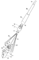
図11に示すように、ブーツ27を固定キャップ5の接続筒部18に装着するとともに、保護チューブ28を所定の位置に設置することによって、光コネクタ1の組み立てが完了する。
As shown in FIG. 11, the optical connector 1 is assembled by attaching the boot 27 to the connecting cylinder portion 18 of the fixed cap 5 and installing the protective tube 28 at a predetermined position.
光コネクタ1では、固定キャップ5を固定部14にネジ止めすることによって抗張力体33を固定する構造を有する。汎用のカシメ固定構造では専用工具が必要となるが、光コネクタ1ではネジ止めを採用するため、専用工具は不要となり、組み立てが容易になる。
また、ネジ止めを採用するため、抗張力体33を強固にハウジング2に固定し、光ファイバケーブル31との接続部分に十分な強度を与えることができる。
また、光コネクタ1では、固定構造における部品点数が少なく構造が簡略であるため、組み立て工程数を削減することができる。構造が簡略であるため、光コネクタ1の小型化、すなわち全長を短くすることも可能となる。 Theoptical connector 1 has a structure in which the strength member 33 is fixed by screwing the fixing cap 5 to the fixing portion 14. The general-purpose caulking fixing structure requires a dedicated tool. However, since the optical connector 1 employs screwing, the dedicated tool is not required and assembly is facilitated.
In addition, since the screwing is employed, thestrength member 33 can be firmly fixed to the housing 2 and sufficient strength can be given to the connection portion with the optical fiber cable 31.
Moreover, in theoptical connector 1, since the number of parts in the fixed structure is small and the structure is simple, the number of assembly steps can be reduced. Since the structure is simple, the optical connector 1 can be downsized, that is, the entire length can be shortened.
また、ネジ止めを採用するため、抗張力体33を強固にハウジング2に固定し、光ファイバケーブル31との接続部分に十分な強度を与えることができる。
また、光コネクタ1では、固定構造における部品点数が少なく構造が簡略であるため、組み立て工程数を削減することができる。構造が簡略であるため、光コネクタ1の小型化、すなわち全長を短くすることも可能となる。 The
In addition, since the screwing is employed, the
Moreover, in the
汎用のカシメ固定構造では、一度取り付けたカシメ部材の取り外しは難しいため、誤操作などにより抗張力体の固定が不十分となった場合には、カシメ部材を取り付けた部分の光ファイバを切除して、新たな端末にカシメ部材の取り付け作業を行う必要がある。
これに対し、光コネクタ1では、ネジ止めを採用するので、誤操作などにより抗張力体33の固定が不十分となった場合は、固定キャップ5を外して、固定キャップ5の装着をやり直すことができる。従って、光コネクタ1の組み立ての歩留まりが良くなる。
なお、光コネクタ端部のケブラ固定構造は、現場組立型の光コネクタには限定されず、他方式の光コネクタにも適用できる。 With the general caulking fixing structure, it is difficult to remove the caulking member once attached. If the tension member is insufficiently fixed due to misoperation, etc., cut off the optical fiber at the part where the caulking member is attached, It is necessary to perform a caulking member mounting operation on a simple terminal.
On the other hand, since theoptical connector 1 employs screwing, the fixing cap 5 can be removed and the fixing cap 5 can be mounted again if the tensile strength member 33 is insufficiently fixed due to an erroneous operation or the like. . Therefore, the assembly yield of the optical connector 1 is improved.
The Kevlar fixing structure at the end of the optical connector is not limited to an on-site assembly type optical connector, but can be applied to other types of optical connectors.
これに対し、光コネクタ1では、ネジ止めを採用するので、誤操作などにより抗張力体33の固定が不十分となった場合は、固定キャップ5を外して、固定キャップ5の装着をやり直すことができる。従って、光コネクタ1の組み立ての歩留まりが良くなる。
なお、光コネクタ端部のケブラ固定構造は、現場組立型の光コネクタには限定されず、他方式の光コネクタにも適用できる。 With the general caulking fixing structure, it is difficult to remove the caulking member once attached. If the tension member is insufficiently fixed due to misoperation, etc., cut off the optical fiber at the part where the caulking member is attached, It is necessary to perform a caulking member mounting operation on a simple terminal.
On the other hand, since the
The Kevlar fixing structure at the end of the optical connector is not limited to an on-site assembly type optical connector, but can be applied to other types of optical connectors.
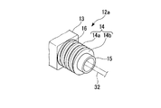
図12は、本発明の第2の実施形態である光コネクタ41を示す断面図である。図13は、光コネクタ41の固定部14を示す斜視図である。図14は、光コネクタ41の保護チューブ43を示す斜視図である。
以下の説明において、既出の構成は同一符号を付してその説明を省略する。
図12に示すように、光コネクタ41は、ハウジング2と、ハウジング2内に設けられたクランプ部付きフェルール3と、クランプ部付きフェルール3を前方に付勢するスプリング4と、ハウジング2に装着される固定キャップ42と、引留リング6と、保護チューブ43と、保護チューブ43を光ファイバケーブル31に引き留める引留具44とを備えている。 FIG. 12 is a cross-sectional view showing anoptical connector 41 according to the second embodiment of the present invention. FIG. 13 is a perspective view showing the fixing portion 14 of the optical connector 41. FIG. 14 is a perspective view showing the protective tube 43 of the optical connector 41.
In the following description, the same components as those described above are denoted by the same reference numerals and description thereof is omitted.
As shown in FIG. 12, theoptical connector 41 is mounted on the housing 2, the ferrule 3 with a clamp portion provided in the housing 2, a spring 4 that biases the ferrule 3 with a clamp portion forward, and the housing 2. A fixing cap 42, a retaining ring 6, a protective tube 43, and a retainer 44 that secures the protective tube 43 to the optical fiber cable 31.
以下の説明において、既出の構成は同一符号を付してその説明を省略する。
図12に示すように、光コネクタ41は、ハウジング2と、ハウジング2内に設けられたクランプ部付きフェルール3と、クランプ部付きフェルール3を前方に付勢するスプリング4と、ハウジング2に装着される固定キャップ42と、引留リング6と、保護チューブ43と、保護チューブ43を光ファイバケーブル31に引き留める引留具44とを備えている。 FIG. 12 is a cross-sectional view showing an
In the following description, the same components as those described above are denoted by the same reference numerals and description thereof is omitted.
As shown in FIG. 12, the
図13に示すように、光コネクタ41は、図6に示す光コネクタ1と異なり、固定部14に溝部が形成されておらず、ネジ部16は固定部14の全周にわたって形成されている。
As shown in FIG. 13, the optical connector 41 is different from the optical connector 1 shown in FIG. 6 in that no groove portion is formed in the fixing portion 14 and the screw portion 16 is formed over the entire circumference of the fixing portion 14.
図12に示すように、固定キャップ42は、樹脂などからなり、固定部14に取り付けられる装着部46と、装着部46の後端に連設された連設筒部47とからなる。
装着部46は円筒状に形成され、内面には固定部14のネジ部16に螺合するネジ部48が形成されている。 As shown in FIG. 12, the fixedcap 42 is made of resin or the like, and includes a mounting portion 46 attached to the fixing portion 14 and a continuous tube portion 47 provided continuously at the rear end of the mounting portion 46.
The mountingportion 46 is formed in a cylindrical shape, and a screw portion 48 that is screwed into the screw portion 16 of the fixing portion 14 is formed on the inner surface.
装着部46は円筒状に形成され、内面には固定部14のネジ部16に螺合するネジ部48が形成されている。 As shown in FIG. 12, the fixed
The mounting
連設筒部47は、ほぼ一定内径の大径部49と、大径部49の後端から後方に向けて形成された小径部50とを有する円筒状に形成されている。
小径部50の内径は大径部49の内径より小さくされ、大径部49と小径部50との境界には、軸方向に垂直な面をなす係止段部51が形成されている。 Thecontinuous cylinder portion 47 is formed in a cylindrical shape having a large diameter portion 49 having a substantially constant inner diameter and a small diameter portion 50 formed rearward from the rear end of the large diameter portion 49.
The inner diameter of the small-diameter portion 50 is smaller than the inner diameter of the large-diameter portion 49, and a locking step portion 51 that forms a surface perpendicular to the axial direction is formed at the boundary between the large-diameter portion 49 and the small-diameter portion 50.
小径部50の内径は大径部49の内径より小さくされ、大径部49と小径部50との境界には、軸方向に垂直な面をなす係止段部51が形成されている。 The
The inner diameter of the small-
連設筒部47の前端部内面には、引留リング6が配置される環状のリング用凹部52が形成されている。
連設筒部47の内部は、光ファイバ32が挿通する光ファイバ挿通部53となっている。
連設筒部47の後部は、後端側ほど外径および肉厚が小さくなるように形成されており、これによって後端に近いほど曲がりやすくなっている。なお、屈曲性を高めるため、テーパ部50には周方向に沿うスリット(図示略)を形成してもよい。
固定キャップ42は、ゴムなどの可撓性材料で形成するのが好ましい。 Anannular ring recess 52 in which the retaining ring 6 is disposed is formed on the inner surface of the front end portion of the continuous tube portion 47.
The inside of thecontinuous tube portion 47 is an optical fiber insertion portion 53 through which the optical fiber 32 is inserted.
The rear portion of thecontinuous tube portion 47 is formed so that the outer diameter and the wall thickness become smaller toward the rear end side, so that the closer to the rear end, the easier it is to bend. In order to enhance the flexibility, the tapered portion 50 may be formed with a slit (not shown) along the circumferential direction.
The fixingcap 42 is preferably formed of a flexible material such as rubber.
連設筒部47の内部は、光ファイバ32が挿通する光ファイバ挿通部53となっている。
連設筒部47の後部は、後端側ほど外径および肉厚が小さくなるように形成されており、これによって後端に近いほど曲がりやすくなっている。なお、屈曲性を高めるため、テーパ部50には周方向に沿うスリット(図示略)を形成してもよい。
固定キャップ42は、ゴムなどの可撓性材料で形成するのが好ましい。 An
The inside of the
The rear portion of the
The fixing
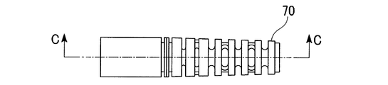
図12および図14に示すように、保護チューブ43は、ポリエステルエラストマーなどの樹脂によって一体的に形成されており、円筒状に形成されたチューブ本体54と、チューブ本体54の前端に形成されたフランジ部55(係止突起部)とを備えている。
チューブ本体54の外径は、小径部50の内径にほぼ等しいか、または若干小さくすることができる。チューブ本体54は小径部50に挿通し、固定キャップ42の後端から後方に延出している。 As shown in FIGS. 12 and 14, theprotective tube 43 is integrally formed of a resin such as polyester elastomer, and has a tube body 54 formed in a cylindrical shape and a flange formed at the front end of the tube body 54. Part 55 (locking projection part).
The outer diameter of thetube body 54 can be substantially equal to or slightly smaller than the inner diameter of the small diameter portion 50. The tube body 54 is inserted through the small diameter portion 50 and extends rearward from the rear end of the fixed cap 42.
チューブ本体54の外径は、小径部50の内径にほぼ等しいか、または若干小さくすることができる。チューブ本体54は小径部50に挿通し、固定キャップ42の後端から後方に延出している。 As shown in FIGS. 12 and 14, the
The outer diameter of the
フランジ部55は、保護チューブ43が固定キャップ42から後方に抜けるのを阻止するものであって、チューブ本体54の外面から外方に突出した環状の突起であり、その外径は、少なくとも小径部50の内径より大きくされている。フランジ部55の外径は、大径部49の内径にほぼ等しいか、または若干小さくすることができる。
チューブ本体54は固定キャップ42の小径部50に挿通しており、フランジ部55は大径部49内に位置しているため、保護チューブ43に後方への力が加えられると、フランジ部55の後端面が係止段部51に当接し、それ以上の後方移動が規制される。
保護チューブ43の内部は、光ファイバ32が挿通する光ファイバ挿通部56となっている。 Theflange portion 55 prevents the protective tube 43 from coming out rearward from the fixed cap 42, and is an annular protrusion protruding outward from the outer surface of the tube main body 54. The outer diameter of the flange portion 55 is at least a small diameter portion. It is larger than the inner diameter of 50. The outer diameter of the flange portion 55 can be made substantially equal to or slightly smaller than the inner diameter of the large diameter portion 49.
Since the tubemain body 54 is inserted into the small diameter portion 50 of the fixed cap 42 and the flange portion 55 is located in the large diameter portion 49, when a rearward force is applied to the protective tube 43, The rear end surface comes into contact with the locking step portion 51, and further rearward movement is restricted.
Inside theprotective tube 43 is an optical fiber insertion portion 56 through which the optical fiber 32 is inserted.
チューブ本体54は固定キャップ42の小径部50に挿通しており、フランジ部55は大径部49内に位置しているため、保護チューブ43に後方への力が加えられると、フランジ部55の後端面が係止段部51に当接し、それ以上の後方移動が規制される。
保護チューブ43の内部は、光ファイバ32が挿通する光ファイバ挿通部56となっている。 The
Since the tube
Inside the
保護チューブ43は、固定キャップ42に対し固定されていない。このため、固定キャップ42を固定部14にネジ止めする際に、保護チューブ43に回転力が加えられることはない。
なお、フランジ部55の形成位置は、チューブ本体54の端部に限定されず、チューブ本体54の両端部間の中間位置であってもよい。また、本発明において係止突起部は、固定キャップの係止段部に係止して後方移動を阻止する構造であればよく、図示するフランジ部の形状に限定されず、例えば周方向に不連続な突起であってもよい。 Theprotective tube 43 is not fixed to the fixed cap 42. For this reason, when the fixing cap 42 is screwed to the fixing portion 14, no rotational force is applied to the protective tube 43.
In addition, the formation position of theflange part 55 is not limited to the edge part of the tube main body 54, The intermediate position between the both ends of the tube main body 54 may be sufficient. Further, in the present invention, the locking projections only need to be structured to be locked to the locking step of the fixed cap and prevent backward movement, and are not limited to the shape of the flange portion shown in the figure. It may be a continuous protrusion.
なお、フランジ部55の形成位置は、チューブ本体54の端部に限定されず、チューブ本体54の両端部間の中間位置であってもよい。また、本発明において係止突起部は、固定キャップの係止段部に係止して後方移動を阻止する構造であればよく、図示するフランジ部の形状に限定されず、例えば周方向に不連続な突起であってもよい。 The
In addition, the formation position of the
図12に示すように、引留具44は、断面C字形に形成され、その弾性力(クランプ力)によって保護チューブ43を押さえつけて光ファイバケーブル31の外被34に固定している(図16および図17を参照)。
As shown in FIG. 12, the retainer 44 is formed in a C-shaped cross section and presses the protective tube 43 by its elastic force (clamping force) to fix it to the jacket 34 of the optical fiber cable 31 (see FIG. 16 and FIG. 12). See FIG.
次に、光ファイバケーブル31の端末に光コネクタ41を組み立てる方法を説明する。
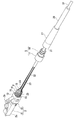
図15および図16に示すように、抗張力体33を引留リング6によって延出筒部15に引き留め、次いで固定キャップ42を固定部14にネジ止めする。これによって、抗張力体33は、固定キャップ42と固定部14との間に挟まれて固定される。
次いで、図17に示すように、引留具44を保護チューブ43の外周面に装着することによって、保護チューブ43を光ファイバケーブル31の外被34に固定する。 Next, a method for assembling theoptical connector 41 at the end of the optical fiber cable 31 will be described.
As shown in FIGS. 15 and 16, thestrength member 33 is fastened to the extension cylinder portion 15 by the retaining ring 6, and then the fixing cap 42 is screwed to the fixing portion 14. Thereby, the strength member 33 is sandwiched and fixed between the fixing cap 42 and the fixing portion 14.
Next, as shown in FIG. 17, theprotective tube 43 is fixed to the jacket 34 of the optical fiber cable 31 by attaching the retainer 44 to the outer peripheral surface of the protective tube 43.
図15および図16に示すように、抗張力体33を引留リング6によって延出筒部15に引き留め、次いで固定キャップ42を固定部14にネジ止めする。これによって、抗張力体33は、固定キャップ42と固定部14との間に挟まれて固定される。
次いで、図17に示すように、引留具44を保護チューブ43の外周面に装着することによって、保護チューブ43を光ファイバケーブル31の外被34に固定する。 Next, a method for assembling the
As shown in FIGS. 15 and 16, the
Next, as shown in FIG. 17, the
光コネクタ41では、固定キャップ42を固定部14にネジ止めすることによって抗張力体33を固定する構造を有するので、組み立てが容易であり、しかも抗張力体33を強固にハウジング2に固定し、接続部分に十分な強度を与えることができる。
また、ネジ部16が固定部14の全周にわたって形成されているので、ネジ嵌合する固定キャップ42と固定部14との間に抗張力体33を確実に挟み込むことができる。従って、抗張力体33の固定強度を高めることができる。 Since theoptical connector 41 has a structure in which the strength member 33 is fixed by screwing the fixing cap 42 to the fixing portion 14, it is easy to assemble, and the strength member 33 is firmly fixed to the housing 2, and the connection portion Can provide sufficient strength.
Further, since thescrew portion 16 is formed over the entire circumference of the fixing portion 14, the tensile strength body 33 can be securely sandwiched between the fixing cap 42 and the fixing portion 14 that are screw-fitted. Therefore, the fixing strength of the strength member 33 can be increased.
また、ネジ部16が固定部14の全周にわたって形成されているので、ネジ嵌合する固定キャップ42と固定部14との間に抗張力体33を確実に挟み込むことができる。従って、抗張力体33の固定強度を高めることができる。 Since the
Further, since the
一般に、光ファイバケーブルでは、気温の変動などにより外被が長さ方向に収縮することがある。
これに対し、光コネクタ41では、フランジ部55を有する保護チューブ43が外被34に固定されているので、外被34の収縮により保護チューブ43に後方への力が加えられると、フランジ部55が固定キャップ42の係止段部51に当接し、それ以上の後方移動が規制される。
従って、温度の変動などにより外被34が収縮した場合でも、外被34が光コネクタ41から後方に抜け出るのを防ぐことができる。 In general, in an optical fiber cable, the jacket may contract in the length direction due to a change in temperature or the like.
On the other hand, in theoptical connector 41, the protective tube 43 having the flange portion 55 is fixed to the outer cover 34. Therefore, when a backward force is applied to the protective tube 43 due to contraction of the outer cover 34, the flange portion 55 Comes into contact with the locking step portion 51 of the fixed cap 42 and further rearward movement is restricted.
Therefore, even when thejacket 34 contracts due to temperature fluctuations, it is possible to prevent the jacket 34 from coming out of the optical connector 41 backward.
これに対し、光コネクタ41では、フランジ部55を有する保護チューブ43が外被34に固定されているので、外被34の収縮により保護チューブ43に後方への力が加えられると、フランジ部55が固定キャップ42の係止段部51に当接し、それ以上の後方移動が規制される。
従って、温度の変動などにより外被34が収縮した場合でも、外被34が光コネクタ41から後方に抜け出るのを防ぐことができる。 In general, in an optical fiber cable, the jacket may contract in the length direction due to a change in temperature or the like.
On the other hand, in the
Therefore, even when the
図18~図28は、本発明の光コネクタの他の例を示すものである。
図18~図21に示すように、ストップリング本体12aの端壁部14bの後面には、端壁部14bの周方向に沿う環状突起61が形成され、環状突起61の外周面には、抗張力体33の周方向移動を阻止する複数の移動阻止凹部62が形成されている。
延出筒部15の先端部の外周面には、周方向の一部に乗上げ凸部63が形成されている。乗上げ凸部63は周方向に間隔をおいて複数形成することができる。
基部13の側面13aの後端部には、膨出凸部64が形成されている。膨出凸部64は、基部13と固定キャップ65との間の対向部分の面積を大きくし、これらに挟まれる抗張力体33の固定強度を高めるものである。 18 to 28 show other examples of the optical connector of the present invention.
As shown in FIGS. 18 to 21, anannular projection 61 is formed on the rear surface of the end wall portion 14b of the stop ring body 12a along the circumferential direction of the end wall portion 14b. A plurality of movement preventing recesses 62 that prevent the movement of the body 33 in the circumferential direction are formed.
On the outer peripheral surface of the distal end portion of the extendingcylinder portion 15, a climbing convex portion 63 is formed in a part of the circumferential direction. A plurality of the raised protrusions 63 can be formed at intervals in the circumferential direction.
A bulgingconvex portion 64 is formed at the rear end portion of the side surface 13 a of the base portion 13. The bulging convex portion 64 increases the area of the facing portion between the base portion 13 and the fixing cap 65 and increases the fixing strength of the tensile body 33 sandwiched between them.
図18~図21に示すように、ストップリング本体12aの端壁部14bの後面には、端壁部14bの周方向に沿う環状突起61が形成され、環状突起61の外周面には、抗張力体33の周方向移動を阻止する複数の移動阻止凹部62が形成されている。
延出筒部15の先端部の外周面には、周方向の一部に乗上げ凸部63が形成されている。乗上げ凸部63は周方向に間隔をおいて複数形成することができる。
基部13の側面13aの後端部には、膨出凸部64が形成されている。膨出凸部64は、基部13と固定キャップ65との間の対向部分の面積を大きくし、これらに挟まれる抗張力体33の固定強度を高めるものである。 18 to 28 show other examples of the optical connector of the present invention.
As shown in FIGS. 18 to 21, an
On the outer peripheral surface of the distal end portion of the extending
A bulging
図22~図25に示すように、固定キャップ65は、固定部14に装着される装着部17と、装着部17の後端部から後方に延出する接続筒部18とを有する。
固定キャップ65には、軸方向(前後方向)に沿って一対のスリット66が形成されている。これら一対のスリット66は、装着部17の後部から接続筒部18の前部にかけて、周方向に間隔をおいて、互いに近接した位置に形成されている。
装着部17の内周面には、固定部14のネジ部16に螺合するネジ部19が形成されている。 As shown in FIGS. 22 to 25, the fixingcap 65 includes a mounting portion 17 that is mounted on the fixing portion 14 and a connecting cylinder portion 18 that extends rearward from the rear end portion of the mounting portion 17.
The fixedcap 65 is formed with a pair of slits 66 along the axial direction (front-rear direction). The pair of slits 66 are formed at positions close to each other at intervals in the circumferential direction from the rear part of the mounting part 17 to the front part of the connecting cylinder part 18.
On the inner peripheral surface of the mountingportion 17, a screw portion 19 that is screwed into the screw portion 16 of the fixing portion 14 is formed.
固定キャップ65には、軸方向(前後方向)に沿って一対のスリット66が形成されている。これら一対のスリット66は、装着部17の後部から接続筒部18の前部にかけて、周方向に間隔をおいて、互いに近接した位置に形成されている。
装着部17の内周面には、固定部14のネジ部16に螺合するネジ部19が形成されている。 As shown in FIGS. 22 to 25, the fixing
The fixed
On the inner peripheral surface of the mounting
図23および図25に示すように、接続筒部18の内面には、使用者に操作感(クリック感)を与えるための操作凸部67が形成されている。操作凸部67は、固定キャップ65を固定部14にネジ止めする過程で乗上げ凸部63に至る位置に形成されている。
操作凸部67は、スリット66、66の間の位置に形成されている。スリット66、66間の部分は、操作凸部67が乗上げ凸部63に乗り上げる際に外方に弾性的に撓むことができるため、固定キャップ65のネジ止めに支障が生じることはない。
なお、固定キャップ65は、スリット66および操作凸部67を形成しない構成としてもよい。 As shown in FIG. 23 and FIG. 25, an operationconvex portion 67 is provided on the inner surface of the connection tube portion 18 to give an operation feeling (click feeling) to the user. The operation convex portion 67 is formed at a position reaching the climbing convex portion 63 in the process of screwing the fixing cap 65 to the fixing portion 14.
The operationconvex portion 67 is formed at a position between the slits 66 and 66. The portion between the slits 66 and 66 can be flexed outward when the operation convex portion 67 rides on the climbing convex portion 63, so that there is no problem in screwing the fixing cap 65.
The fixingcap 65 may be configured not to form the slit 66 and the operation convex portion 67.
操作凸部67は、スリット66、66の間の位置に形成されている。スリット66、66間の部分は、操作凸部67が乗上げ凸部63に乗り上げる際に外方に弾性的に撓むことができるため、固定キャップ65のネジ止めに支障が生じることはない。
なお、固定キャップ65は、スリット66および操作凸部67を形成しない構成としてもよい。 As shown in FIG. 23 and FIG. 25, an operation
The operation
The fixing
図23および図24に示すように、接続筒部18の外周面には、抜止め突起69が形成されている。抜止め突起69は、ブーツ70の抜け止めのためのもので、接続筒部18の周方向に沿う環状突起である。
抜止め突起69の後面69aは、後方に向け縮径する方向に傾斜して形成されている。
後面69aの傾斜角度(接続筒部18の軸方向に対する傾斜角度)は、前面69bの傾斜角度より小さくするのが好ましい。図示例では、抜止め突起69は断面略台形とされ、前面69bは軸方向に垂直である。
図26~図28に示すように、比較的軟質の樹脂等からなるブーツ70は抜止め突起69に係止するため、後方への引張力が加えられた場合でも接続筒部18から外れることはない。 As shown in FIG. 23 and FIG. 24, a retainingprotrusion 69 is formed on the outer peripheral surface of the connecting tube portion 18. The retaining protrusion 69 is for preventing the boot 70 from coming off, and is an annular protrusion along the circumferential direction of the connecting cylinder portion 18.
Therear surface 69a of the retaining protrusion 69 is formed so as to be inclined in the direction of reducing the diameter toward the rear.
The inclination angle of therear surface 69a (the inclination angle with respect to the axial direction of the connecting tube portion 18) is preferably smaller than the inclination angle of the front surface 69b. In the illustrated example, the retaining protrusion 69 has a substantially trapezoidal cross section, and the front surface 69b is perpendicular to the axial direction.
As shown in FIGS. 26 to 28, theboot 70 made of a relatively soft resin or the like is locked to the retaining projection 69, so that even when a rearward tensile force is applied, the boot 70 does not come off from the connecting cylinder portion 18. Absent.
抜止め突起69の後面69aは、後方に向け縮径する方向に傾斜して形成されている。
後面69aの傾斜角度(接続筒部18の軸方向に対する傾斜角度)は、前面69bの傾斜角度より小さくするのが好ましい。図示例では、抜止め突起69は断面略台形とされ、前面69bは軸方向に垂直である。
図26~図28に示すように、比較的軟質の樹脂等からなるブーツ70は抜止め突起69に係止するため、後方への引張力が加えられた場合でも接続筒部18から外れることはない。 As shown in FIG. 23 and FIG. 24, a retaining
The
The inclination angle of the
As shown in FIGS. 26 to 28, the
図28および図29に示すように、この光コネクタを組み立てるには、固定キャップ65の装着部17を固定部14にネジ止めする。この際、抗張力体33は、固定部14の外周に配置して固定キャップ65のネジ止めを行うことによって固定キャップ65と固定部14の間に挟み込む(図15を参照)。
図29に示すように、抗張力体33は、束状に集合させた状態で固定キャップ65と固定部14の間に挟み込むことが好ましい。抗張力体33は、複数に分けてそれぞれを束状の集合体にした状態で、固定キャップ65および固定部14の周方向に離間した位置に固定することができる。図示例では、抗張力体33は2つに分けられ、それぞれが束状にまとめられ、固定キャップ65および固定部14の中心軸に対し回転対称となる位置に固定されている。抗張力体33は、2つに限らず、3つ以上の集合体に分けてもよい。抗張力体33は、ストップリング本体12aの基部13と固定キャップ65の前端面との間に挟み込まれることが好ましい。
抗張力体33は、束状に集合させることによって径(集合体の径)が大きくなるため、ストップリング本体12aの基部13と固定キャップ65の前端面との間で強い力で挟み込まれることから、抗張力体33の固定強度が高められる。
また、複数の集合体を周方向に離間した位置に固定することによって、抗張力体33によってストップリング本体12aおよび固定キャップ65に作用する力の偏りを小さくできる。
なお、抗張力体に加わるテンションは、固定キャップ65と固定部14(ネジ部16)の間、および固定キャップ65の周端面と基部13の間で分担して受け止められている。
ストップリング本体12aの基部13には膨出凸部64が形成されているため、固定キャップ65との間の対向部分の面積が大きくなり、これらに挟まれる抗張力体33の固定強度が高められる。 As shown in FIGS. 28 and 29, to assemble this optical connector, the mountingportion 17 of the fixing cap 65 is screwed to the fixing portion 14. At this time, the tensile strength member 33 is disposed on the outer periphery of the fixing portion 14 and screwed to the fixing cap 65 to be sandwiched between the fixing cap 65 and the fixing portion 14 (see FIG. 15).
As shown in FIG. 29, thestrength members 33 are preferably sandwiched between the fixed cap 65 and the fixed portion 14 in a state of being gathered in a bundle. The strength members 33 can be fixed at positions spaced apart in the circumferential direction of the fixing cap 65 and the fixing portion 14 in a state of being divided into a plurality of bundles. In the example shown in the figure, the strength members 33 are divided into two pieces, which are bundled together and fixed at positions that are rotationally symmetric with respect to the central axis of the fixing cap 65 and the fixing portion 14. The strength members 33 are not limited to two, and may be divided into three or more aggregates. The strength member 33 is preferably sandwiched between the base portion 13 of the stop ring main body 12a and the front end surface of the fixed cap 65.
Since the diameter (aggregate diameter) is increased by gathering thestrength members 33 in a bundle shape, the strength members 33 are sandwiched with a strong force between the base portion 13 of the stop ring body 12a and the front end surface of the fixed cap 65. The fixing strength of the strength member 33 is increased.
Further, by fixing the plurality of aggregates at positions spaced apart in the circumferential direction, the bias of the force acting on the stop ringmain body 12a and the fixed cap 65 by the tensile body 33 can be reduced.
The tension applied to the strength member is shared and received between the fixedcap 65 and the fixed portion 14 (screw portion 16) and between the peripheral end surface of the fixed cap 65 and the base portion 13.
Since the bulgingconvex part 64 is formed in the base part 13 of the stop ring main body 12a, the area of the opposing part between the fixing caps 65 becomes large, and the fixing strength of the tensile body 33 sandwiched between these is increased.
図29に示すように、抗張力体33は、束状に集合させた状態で固定キャップ65と固定部14の間に挟み込むことが好ましい。抗張力体33は、複数に分けてそれぞれを束状の集合体にした状態で、固定キャップ65および固定部14の周方向に離間した位置に固定することができる。図示例では、抗張力体33は2つに分けられ、それぞれが束状にまとめられ、固定キャップ65および固定部14の中心軸に対し回転対称となる位置に固定されている。抗張力体33は、2つに限らず、3つ以上の集合体に分けてもよい。抗張力体33は、ストップリング本体12aの基部13と固定キャップ65の前端面との間に挟み込まれることが好ましい。
抗張力体33は、束状に集合させることによって径(集合体の径)が大きくなるため、ストップリング本体12aの基部13と固定キャップ65の前端面との間で強い力で挟み込まれることから、抗張力体33の固定強度が高められる。
また、複数の集合体を周方向に離間した位置に固定することによって、抗張力体33によってストップリング本体12aおよび固定キャップ65に作用する力の偏りを小さくできる。
なお、抗張力体に加わるテンションは、固定キャップ65と固定部14(ネジ部16)の間、および固定キャップ65の周端面と基部13の間で分担して受け止められている。
ストップリング本体12aの基部13には膨出凸部64が形成されているため、固定キャップ65との間の対向部分の面積が大きくなり、これらに挟まれる抗張力体33の固定強度が高められる。 As shown in FIGS. 28 and 29, to assemble this optical connector, the mounting
As shown in FIG. 29, the
Since the diameter (aggregate diameter) is increased by gathering the
Further, by fixing the plurality of aggregates at positions spaced apart in the circumferential direction, the bias of the force acting on the stop ring
The tension applied to the strength member is shared and received between the fixed
Since the bulging
ネジ止めの過程では、固定キャップ65の回転により操作凸部67が乗上げ凸部63に乗り上げ(図18および図25を参照)、さらに回転させると乗上げ凸部63のない位置に至る。操作凸部67が乗上げ凸部63から落下する際には、固定キャップ65を操作する使用者には操作感(クリック感)が与えられるため、使用者がネジ止めの進行度を容易に確認できる。
In the process of screwing, the operation convex portion 67 rides on the climbing convex portion 63 by the rotation of the fixing cap 65 (see FIGS. 18 and 25), and when further rotated, the operation convex portion 63 reaches a position without the riding convex portion 63. When the operation convex part 67 falls from the climbing convex part 63, the user who operates the fixing cap 65 is given an operational feeling (click feeling), so the user can easily confirm the progress of screwing. it can.
図示例では、クランプ部の一対の素子間で光ファイバを突き合わせ接続させる方式(メカニカルスプライス方式)を採用したが、本発明では、光ファイバの接続に他の方式を採用することもできる。例えば、光ファイバケーブル端末に口出しした光ファイバと内蔵光ファイバとを融着接続してもよい。この場合には、融着接続部を補強スリーブで補強してハウジング内に収容することができる。
また、図示例では、光ファイバケーブルからの光ファイバと内蔵光ファイバとが光コネクタ内で接続されるが、本発明は、内蔵光ファイバがない構成、すなわち光ファイバケーブル端末に口出しした光ファイバの先端がそのまま接続端面に露出する構造の光コネクタにも適用できる。
また、図2に示すように、ハウジング2は弾性片11b、12bを備えているが、これに限らず、弾性片をもたない構造のものも採用できる。 In the illustrated example, a system (mechanical splicing system) in which an optical fiber is butt-connected between a pair of elements of the clamp portion is employed. However, in the present invention, another system can be employed for connecting optical fibers. For example, the optical fiber led to the optical fiber cable terminal and the built-in optical fiber may be fusion-connected. In this case, the fusion splicing portion can be reinforced with the reinforcing sleeve and accommodated in the housing.
Further, in the illustrated example, the optical fiber from the optical fiber cable and the built-in optical fiber are connected within the optical connector, but the present invention has a configuration without the built-in optical fiber, that is, the optical fiber led to the end of the optical fiber cable. The present invention can also be applied to an optical connector having a structure in which the tip is exposed to the connection end face as it is.
As shown in FIG. 2, thehousing 2 includes the elastic pieces 11b and 12b. However, the structure is not limited to this, and a structure having no elastic piece can also be adopted.
また、図示例では、光ファイバケーブルからの光ファイバと内蔵光ファイバとが光コネクタ内で接続されるが、本発明は、内蔵光ファイバがない構成、すなわち光ファイバケーブル端末に口出しした光ファイバの先端がそのまま接続端面に露出する構造の光コネクタにも適用できる。
また、図2に示すように、ハウジング2は弾性片11b、12bを備えているが、これに限らず、弾性片をもたない構造のものも採用できる。 In the illustrated example, a system (mechanical splicing system) in which an optical fiber is butt-connected between a pair of elements of the clamp portion is employed. However, in the present invention, another system can be employed for connecting optical fibers. For example, the optical fiber led to the optical fiber cable terminal and the built-in optical fiber may be fusion-connected. In this case, the fusion splicing portion can be reinforced with the reinforcing sleeve and accommodated in the housing.
Further, in the illustrated example, the optical fiber from the optical fiber cable and the built-in optical fiber are connected within the optical connector, but the present invention has a configuration without the built-in optical fiber, that is, the optical fiber led to the end of the optical fiber cable. The present invention can also be applied to an optical connector having a structure in which the tip is exposed to the connection end face as it is.
As shown in FIG. 2, the
本発明によれば、工場外の現場で専用工具を用いることなく組み立てることができる現場組立型の光コネクタおよび光コネクタの組立方法を提供することができる。
According to the present invention, it is possible to provide an on-site assembly type optical connector and an optical connector assembling method that can be assembled without using a dedicated tool at a site outside the factory.
Claims (15)
- 光ファイバと、この光ファイバの長手方向に沿って延在する抗張力体とを一体化した光ファイバケーブルの端末に組み立てられる光コネクタであって、
ハウジングと、このハウジング内に設けられたフェルールと、前記ハウジングに装着される固定キャップとを備え、
前記ハウジングが、外周面にネジ部が形成された固定部を有し、
前記固定キャップは、前記光ファイバケーブル端末から引き出された前記抗張力体を前記ハウジングとの間に挟んだ状態で、前記固定部にネジ止め固定可能であることを特徴とする光コネクタ。 An optical connector assembled to an end of an optical fiber cable in which an optical fiber and a tensile body extending along a longitudinal direction of the optical fiber are integrated,
A housing, a ferrule provided in the housing, and a fixing cap attached to the housing;
The housing has a fixing portion in which a screw portion is formed on the outer peripheral surface;
The optical connector is characterized in that the fixing cap can be screwed and fixed to the fixing portion in a state where the tensile body drawn out from the end of the optical fiber cable is sandwiched between the fixing cap and the housing. - 前記フェルールに内挿された内蔵光ファイバが、前記光ファイバケーブル端末に口出しした前記光ファイバに接続可能であることを特徴とする請求項1に記載の光コネクタ。 2. The optical connector according to claim 1, wherein the built-in optical fiber inserted into the ferrule is connectable to the optical fiber led out to the optical fiber cable terminal.
- 前記固定部の外周面には、前記抗張力体を収容可能な1または複数の溝部が形成されていることを特徴とする請求項1に記載の光コネクタ。 2. The optical connector according to claim 1, wherein one or a plurality of grooves capable of accommodating the strength members are formed on an outer peripheral surface of the fixing portion.
- 前記溝部が複数形成され、これら溝部は、前記光ファイバの挿通方向に対し互いに回転対称となる位置に形成されていることを特徴とする請求項3に記載の光コネクタ。 4. The optical connector according to claim 3, wherein a plurality of the groove portions are formed, and the groove portions are formed at positions that are rotationally symmetric with respect to the insertion direction of the optical fiber.
- 前記固定部の外周面には、全周にわたって前記ネジ部が形成されていることを特徴とする請求項1に記載の光コネクタ。 The optical connector according to claim 1, wherein the screw portion is formed on the outer peripheral surface of the fixed portion over the entire circumference.
- 前記ハウジングに、前記固定キャップのネジ止めに先だって前記抗張力体を前記ハウジングに引き留め可能な引留リングが装着され、
この引留リングは、前記ハウジングとの間に前記抗張力体を挟み込んで引き留め可能であることを特徴とする請求項1に記載の光コネクタ。 A retaining ring capable of retaining the strength member on the housing prior to screwing the fixing cap is attached to the housing,
2. The optical connector according to claim 1, wherein the retaining ring can be retained by sandwiching the strength member between the housing and the housing. 3. - 前記ハウジングが、前記固定部より細径であって前記固定部から後方に延出する延出筒部を有し、
前記引留リングは、前記延出筒部との間に前記抗張力体を挟み込んで引き留め可能であることを特徴とする請求項6に記載の光コネクタ。 The housing has an extended tube portion that is smaller in diameter than the fixed portion and extends rearward from the fixed portion;
The optical connector according to claim 6, wherein the retaining ring can be retained by sandwiching the strength member between the extension tube portion. - 前記光ファイバケーブルの外被に保護チューブが固定され、
この保護チューブが、筒状のチューブ本体と、このチューブ本体から外方に突出する係止突起部を有し、
この係止突起部は、前記固定キャップ内面に形成された係止段部に係止して前記保護チューブの後方移動を阻止するように形成されている請求項1に記載の光コネクタ。 A protective tube is fixed to the jacket of the optical fiber cable,
This protective tube has a tubular tube body and a locking projection that protrudes outward from the tube body,
2. The optical connector according to claim 1, wherein the locking projection is locked to a locking step formed on the inner surface of the fixed cap to prevent backward movement of the protective tube. - 前記抗張力体は、複数の集合体に分けた状態で前記ハウジングの周方向に離間した位置に固定されていることを特徴とする請求項1に記載の光コネクタ。 The optical connector according to claim 1, wherein the tensile body is fixed at a position separated in a circumferential direction of the housing in a state of being divided into a plurality of aggregates.
- 光ファイバと、この光ファイバの長手方向に沿って延在する抗張力体とを一体化した光ファイバケーブルの端末に組み立てられる光コネクタであって、
コネクタ本体の後端に、外周面にネジ部が形成された固定部を有し、
前記固定部には、固定キャップがネジ止め固定可能であり、
前記固定キャップは、前記光ファイバケーブル端末から引き出された前記抗張力体を前記コネクタ本体との間に挟んだ状態で、前記固定部にネジ止め固定可能であることを特徴とする光コネクタ。 An optical connector assembled to an end of an optical fiber cable in which an optical fiber and a tensile body extending along a longitudinal direction of the optical fiber are integrated,
At the rear end of the connector body, it has a fixed part with a screw part formed on the outer peripheral surface,
A fixing cap can be fixed with screws to the fixing portion,
The optical connector is characterized in that the fixing cap can be screwed and fixed to the fixing portion in a state where the strength member drawn out from the optical fiber cable terminal is sandwiched between the fixing cap and the connector main body. - 光ファイバと、この光ファイバの長手方向に沿って延在する抗張力体とを一体化した光ファイバケーブルの端末に、光コネクタを組み立てる方法であって、
前記光コネクタが、ハウジングと、このハウジング内に設けられたフェルールと、前記ハウジングに装着される固定キャップとを備え、
前記ハウジングが、外周面にネジ部が形成された固定部を有し、
前記固定キャップは、前記固定部にネジ止め固定可能とされ、
前記フェルールに内挿された内蔵光ファイバに、前記光ファイバケーブル端末に口出しした前記光ファイバを突き合わせ接続し、
その後、前記光ファイバケーブル端末から引き出された前記抗張力体を前記ハウジングとの間に挟んだ状態で、前記固定キャップを前記固定部にネジ止め固定することを特徴とする光コネクタの組立方法。 A method of assembling an optical connector at an end of an optical fiber cable in which an optical fiber and a tensile body extending along the longitudinal direction of the optical fiber are integrated.
The optical connector includes a housing, a ferrule provided in the housing, and a fixing cap attached to the housing.
The housing has a fixing portion in which a screw portion is formed on the outer peripheral surface;
The fixing cap can be fixed with screws to the fixing portion.
The built-in optical fiber inserted into the ferrule is connected to the optical fiber butt-out to the optical fiber cable terminal,
Thereafter, the fixing cap is screwed and fixed to the fixing portion in a state where the tensile body drawn from the optical fiber cable end is sandwiched between the housing and the housing. - 前記固定キャップのネジ止めに先だって、引留リングによって、前記抗張力体を前記ハウジングとの間に挟み込んで引き留めることを特徴とする請求項11に記載の光コネクタの組立方法。 12. The method of assembling an optical connector according to claim 11, wherein, prior to screwing the fixing cap, the strength member is sandwiched between the housing and retained by a retaining ring.
- 前記固定キャップのネジ止めに先だって、前記抗張力体を、複数の集合体に分けた状態で前記ハウジングの周方向に離間した位置に配置することを特徴とする請求項11に記載の光コネクタの組立方法。 The optical connector assembly according to claim 11, wherein prior to screwing the fixing cap, the strength members are arranged at positions spaced apart in the circumferential direction of the housing in a state of being divided into a plurality of aggregates. Method.
- 光ファイバと、この光ファイバの長手方向に沿って延在する抗張力体とを一体化した光ファイバケーブルの端末に、光コネクタを組み立てる方法であって、
前記光コネクタが、コネクタ本体の後端に、外周面にネジ部が形成された固定部を有し、前記固定部に、固定キャップがネジ止め固定可能とされ、
前記光ファイバケーブル端末から引き出された前記抗張力体を前記コネクタ本体との間に挟んだ状態で、前記固定キャップを前記固定部にネジ止め固定することを特徴とする光コネクタの組立方法。 A method of assembling an optical connector at an end of an optical fiber cable in which an optical fiber and a tensile body extending along the longitudinal direction of the optical fiber are integrated.
The optical connector has a fixing portion having a screw portion formed on the outer peripheral surface at the rear end of the connector body, and a fixing cap can be fixed to the fixing portion with screws.
An optical connector assembling method, wherein the fixing cap is screwed and fixed to the fixing portion in a state where the tensile body drawn out from the optical fiber cable terminal is sandwiched between the connector main body. - 前記固定キャップのネジ止めに先だって、前記抗張力体を、複数の集合体に分けた状態で前記ハウジングの周方向に離間した位置に配置することを特徴とする請求項14に記載の光コネクタの組立方法。 15. The optical connector assembly according to claim 14, wherein, prior to screwing the fixing cap, the strength members are arranged at positions spaced apart in the circumferential direction of the housing in a state of being divided into a plurality of aggregates. Method.
Priority Applications (3)
| Application Number | Priority Date | Filing Date | Title |
|---|---|---|---|
| EP09794219.7A EP2296023B1 (en) | 2008-07-10 | 2009-01-09 | Optical connector and method for assembling optical connector |
| CN2009801257138A CN102084277A (en) | 2008-07-10 | 2009-01-09 | Optical connector and method for assembling the same |
| US12/985,704 US8616784B2 (en) | 2007-07-10 | 2011-01-06 | Optical connector with a screw portion and method of assembling the optical connector |
Applications Claiming Priority (2)
| Application Number | Priority Date | Filing Date | Title |
|---|---|---|---|
| JP2008-180694 | 2008-07-10 | ||
| JP2008180694A JP5172510B2 (en) | 2007-07-10 | 2008-07-10 | Optical connector and optical connector assembling method |
Related Child Applications (1)
| Application Number | Title | Priority Date | Filing Date |
|---|---|---|---|
| US12/985,704 Continuation US8616784B2 (en) | 2007-07-10 | 2011-01-06 | Optical connector with a screw portion and method of assembling the optical connector |
Publications (1)
| Publication Number | Publication Date |
|---|---|
| WO2010004772A1 true WO2010004772A1 (en) | 2010-01-14 |
Family
ID=41507812
Family Applications (1)
| Application Number | Title | Priority Date | Filing Date |
|---|---|---|---|
| PCT/JP2009/050204 WO2010004772A1 (en) | 2007-07-10 | 2009-01-09 | Optical connector and method for assembling optical connector |
Country Status (3)
| Country | Link |
|---|---|
| EP (1) | EP2296023B1 (en) |
| CN (2) | CN102084277A (en) |
| WO (1) | WO2010004772A1 (en) |
Cited By (4)
| Publication number | Priority date | Publication date | Assignee | Title |
|---|---|---|---|---|
| WO2011142436A1 (en) * | 2010-05-14 | 2011-11-17 | 住友電気工業株式会社 | Fiber-optic cable terminal fixture and fiber-optic cable terminal fixing method |
| US8758721B2 (en) | 2008-05-30 | 2014-06-24 | Skyworks Solutions, Inc. | Enhanced hexagonal ferrite material and methods of preparation thereof |
| EP2615482A4 (en) * | 2010-09-06 | 2016-03-02 | Autonetworks Technologies Ltd | Engagement member-equipped optical fiber cable |
| WO2018135235A1 (en) * | 2017-01-20 | 2018-07-26 | 日本通信電材株式会社 | Optical connector |
Families Citing this family (7)
| Publication number | Priority date | Publication date | Assignee | Title |
|---|---|---|---|---|
| JP5145416B2 (en) * | 2009-02-13 | 2013-02-20 | 株式会社フジクラ | Optical connector and optical connector assembling method |
| JP2012013913A (en) | 2010-06-30 | 2012-01-19 | Suncall Corp | Optical connector |
| US8724937B2 (en) | 2011-12-20 | 2014-05-13 | International Business Machines Corporation | Fiber to wafer interface |
| US8534927B1 (en) | 2012-03-23 | 2013-09-17 | International Business Machines Corporation | Flexible fiber to wafer interface |
| US9243784B2 (en) | 2012-12-20 | 2016-01-26 | International Business Machines Corporation | Semiconductor photonic package |
| US9400356B2 (en) | 2013-03-14 | 2016-07-26 | International Business Machines Corporation | Fiber pigtail with integrated lid |
| US8923665B2 (en) | 2013-03-15 | 2014-12-30 | International Business Machines Corporation | Material structures for front-end of the line integration of optical polarization splitters and rotators |
Citations (5)
| Publication number | Priority date | Publication date | Assignee | Title |
|---|---|---|---|---|
| JPH027612U (en) * | 1988-06-29 | 1990-01-18 | ||
| JPH10206687A (en) | 1997-01-24 | 1998-08-07 | Hirose Electric Co Ltd | Optical fiber connector |
| US6206581B1 (en) | 1999-10-06 | 2001-03-27 | Lucent Technologies Inc. | Optical connector having a one-piece housing |
| JP2007187724A (en) * | 2006-01-11 | 2007-07-26 | Fujikura Ltd | Optical fiber cord with connector |
| JP2008180694A (en) | 2006-12-28 | 2008-08-07 | Jfe Steel Kk | Configuration determination method of structure |
Family Cites Families (6)
| Publication number | Priority date | Publication date | Assignee | Title |
|---|---|---|---|---|
| JPS6035041B2 (en) * | 1980-09-06 | 1985-08-12 | 日本電信電話株式会社 | fiber optic cable connector |
| US5062683A (en) * | 1990-07-09 | 1991-11-05 | Molex Incorporated | Strain relief connector for optical fiber |
| US5394497A (en) * | 1994-02-22 | 1995-02-28 | The Whitaker Corporation | Captivated fiber optic connector |
| US5644673A (en) * | 1996-01-16 | 1997-07-01 | Lockheed Martin Corp. | Optical-fiber-cable to bulkhead connector |
| US7270487B2 (en) * | 2004-04-30 | 2007-09-18 | Corning Cable Systems Llc | Field installable optical fiber connector |
| US7241056B1 (en) * | 2006-06-13 | 2007-07-10 | Panduit Corp. | Reversible fiber optic connector |
-
2009
- 2009-01-09 CN CN2009801257138A patent/CN102084277A/en active Pending
- 2009-01-09 WO PCT/JP2009/050204 patent/WO2010004772A1/en active Application Filing
- 2009-01-09 CN CN201510810273.7A patent/CN105403957B/en active Active
- 2009-01-09 EP EP09794219.7A patent/EP2296023B1/en active Active
Patent Citations (5)
| Publication number | Priority date | Publication date | Assignee | Title |
|---|---|---|---|---|
| JPH027612U (en) * | 1988-06-29 | 1990-01-18 | ||
| JPH10206687A (en) | 1997-01-24 | 1998-08-07 | Hirose Electric Co Ltd | Optical fiber connector |
| US6206581B1 (en) | 1999-10-06 | 2001-03-27 | Lucent Technologies Inc. | Optical connector having a one-piece housing |
| JP2007187724A (en) * | 2006-01-11 | 2007-07-26 | Fujikura Ltd | Optical fiber cord with connector |
| JP2008180694A (en) | 2006-12-28 | 2008-08-07 | Jfe Steel Kk | Configuration determination method of structure |
Non-Patent Citations (2)
| Title |
|---|
| DAIGO SAITO ET AL.: "Hikari Fiber Cord-yo Genba Kumitate Hikari Connector", 2008 NEN THE INSTITUTE OF ELECTRONICS, INFORMATION AND COMMUNICATION ENGINEERS SOGO TAIKAI KOEN RONBUNSHU TSUSHIN 2, 5 March 2008 (2008-03-05), pages 301, XP008139186 * |
| See also references of EP2296023A4 |
Cited By (7)
| Publication number | Priority date | Publication date | Assignee | Title |
|---|---|---|---|---|
| US8758721B2 (en) | 2008-05-30 | 2014-06-24 | Skyworks Solutions, Inc. | Enhanced hexagonal ferrite material and methods of preparation thereof |
| WO2011142436A1 (en) * | 2010-05-14 | 2011-11-17 | 住友電気工業株式会社 | Fiber-optic cable terminal fixture and fiber-optic cable terminal fixing method |
| US8801300B2 (en) | 2010-05-14 | 2014-08-12 | Sumitomo Electric Industries, Ltd. | Fiber optic cable end fixture and fiber optic cable end fixing method |
| EP2615482A4 (en) * | 2010-09-06 | 2016-03-02 | Autonetworks Technologies Ltd | Engagement member-equipped optical fiber cable |
| WO2018135235A1 (en) * | 2017-01-20 | 2018-07-26 | 日本通信電材株式会社 | Optical connector |
| JPWO2018135235A1 (en) * | 2017-01-20 | 2019-11-07 | 日本通信電材株式会社 | Optical connector |
| JP7089485B2 (en) | 2017-01-20 | 2022-06-22 | 日本通信電材株式会社 | Optical connector |
Also Published As
| Publication number | Publication date |
|---|---|
| EP2296023A1 (en) | 2011-03-16 |
| CN105403957A (en) | 2016-03-16 |
| EP2296023B1 (en) | 2017-08-09 |
| EP2296023A4 (en) | 2013-12-04 |
| CN102084277A (en) | 2011-06-01 |
| CN105403957B (en) | 2017-08-15 |
Similar Documents
| Publication | Publication Date | Title |
|---|---|---|
| JP5172510B2 (en) | Optical connector and optical connector assembling method | |
| WO2010004772A1 (en) | Optical connector and method for assembling optical connector | |
| JP3066739B2 (en) | General-purpose optical connector and basic plug | |
| JP4467322B2 (en) | Alignable optical fiber connector | |
| WO2016206594A1 (en) | Optical fiber connector assembly | |
| AU2014402913B2 (en) | Optical fiber connector assembly | |
| JP2008191410A (en) | Optical connector | |
| WO2012137954A1 (en) | Optical connector | |
| JP5145416B2 (en) | Optical connector and optical connector assembling method | |
| JP2008268280A (en) | Optical connector | |
| US20080175540A1 (en) | Optical Connector Suitable for Field Assembly | |
| CA3041438C (en) | Connector-attached optical fiber cord | |
| JP5873760B2 (en) | Optical connector | |
| JP5276905B2 (en) | Optical fiber with connector and method of assembling optical connector | |
| US10359581B2 (en) | Clamp member, optical connector, and manufacturing method of optical connector | |
| JP7123632B2 (en) | optical connector | |
| JP2005134549A (en) | Optical connector | |
| JPWO2018025337A1 (en) | Optical connector plug | |
| JP2011039162A (en) | Optical connector | |
| JP4481234B2 (en) | Optical connector |
Legal Events
| Date | Code | Title | Description |
|---|---|---|---|
| WWE | Wipo information: entry into national phase |
Ref document number: 200980125713.8 Country of ref document: CN |
|
| 121 | Ep: the epo has been informed by wipo that ep was designated in this application |
Ref document number: 09794219 Country of ref document: EP Kind code of ref document: A1 |
|
| REEP | Request for entry into the european phase |
Ref document number: 2009794219 Country of ref document: EP |
|
| WWE | Wipo information: entry into national phase |
Ref document number: 2009794219 Country of ref document: EP |
|
| NENP | Non-entry into the national phase |
Ref country code: DE |