WO2010002186A2 - Apparatus and method for channel estimation in a mobile communication system - Google Patents
Apparatus and method for channel estimation in a mobile communication system Download PDFInfo
- Publication number
- WO2010002186A2 WO2010002186A2 PCT/KR2009/003579 KR2009003579W WO2010002186A2 WO 2010002186 A2 WO2010002186 A2 WO 2010002186A2 KR 2009003579 W KR2009003579 W KR 2009003579W WO 2010002186 A2 WO2010002186 A2 WO 2010002186A2
- Authority
- WO
- WIPO (PCT)
- Prior art keywords
- cir
- channel
- group
- power
- region
- Prior art date
Links
- 238000000034 method Methods 0.000 title claims abstract description 48
- 238000010295 mobile communication Methods 0.000 title claims abstract description 13
- 230000004044 response Effects 0.000 claims abstract description 9
- 239000011159 matrix material Substances 0.000 claims description 16
- 230000008569 process Effects 0.000 claims description 14
- 238000010586 diagram Methods 0.000 description 11
- 230000015556 catabolic process Effects 0.000 description 6
- 238000006731 degradation reaction Methods 0.000 description 6
- 238000004891 communication Methods 0.000 description 4
- 238000012546 transfer Methods 0.000 description 4
- 239000006185 dispersion Substances 0.000 description 2
- 230000002708 enhancing effect Effects 0.000 description 2
- 230000001965 increasing effect Effects 0.000 description 2
- 230000005540 biological transmission Effects 0.000 description 1
- 238000006243 chemical reaction Methods 0.000 description 1
- 238000004040 coloring Methods 0.000 description 1
- 238000010276 construction Methods 0.000 description 1
- 239000000284 extract Substances 0.000 description 1
- 238000012986 modification Methods 0.000 description 1
- 230000004048 modification Effects 0.000 description 1
- 230000008520 organization Effects 0.000 description 1
- 238000012545 processing Methods 0.000 description 1
- 229920006395 saturated elastomer Polymers 0.000 description 1
- 230000003595 spectral effect Effects 0.000 description 1
- 230000002123 temporal effect Effects 0.000 description 1
Images


Classifications
-
- H—ELECTRICITY
- H04—ELECTRIC COMMUNICATION TECHNIQUE
- H04B—TRANSMISSION
- H04B17/00—Monitoring; Testing
- H04B17/30—Monitoring; Testing of propagation channels
- H04B17/309—Measuring or estimating channel quality parameters
- H04B17/336—Signal-to-interference ratio [SIR] or carrier-to-interference ratio [CIR]
-
- H—ELECTRICITY
- H04—ELECTRIC COMMUNICATION TECHNIQUE
- H04L—TRANSMISSION OF DIGITAL INFORMATION, e.g. TELEGRAPHIC COMMUNICATION
- H04L25/00—Baseband systems
- H04L25/02—Details ; arrangements for supplying electrical power along data transmission lines
- H04L25/0202—Channel estimation
- H04L25/024—Channel estimation channel estimation algorithms
- H04L25/0242—Channel estimation channel estimation algorithms using matrix methods
-
- H—ELECTRICITY
- H04—ELECTRIC COMMUNICATION TECHNIQUE
- H04B—TRANSMISSION
- H04B17/00—Monitoring; Testing
- H04B17/20—Monitoring; Testing of receivers
- H04B17/26—Monitoring; Testing of receivers using historical data, averaging values or statistics
-
- H—ELECTRICITY
- H04—ELECTRIC COMMUNICATION TECHNIQUE
- H04B—TRANSMISSION
- H04B17/00—Monitoring; Testing
- H04B17/30—Monitoring; Testing of propagation channels
-
- H—ELECTRICITY
- H04—ELECTRIC COMMUNICATION TECHNIQUE
- H04L—TRANSMISSION OF DIGITAL INFORMATION, e.g. TELEGRAPHIC COMMUNICATION
- H04L25/00—Baseband systems
- H04L25/02—Details ; arrangements for supplying electrical power along data transmission lines
- H04L25/0202—Channel estimation
- H04L25/0204—Channel estimation of multiple channels
-
- H—ELECTRICITY
- H04—ELECTRIC COMMUNICATION TECHNIQUE
- H04L—TRANSMISSION OF DIGITAL INFORMATION, e.g. TELEGRAPHIC COMMUNICATION
- H04L25/00—Baseband systems
- H04L25/02—Details ; arrangements for supplying electrical power along data transmission lines
- H04L25/0202—Channel estimation
- H04L25/024—Channel estimation channel estimation algorithms
- H04L25/0256—Channel estimation using minimum mean square error criteria
Definitions
- the present invention relates generally to an apparatus and a method for channel estimation in a mobile communication system and more particularly, to an apparatus and a method for estimating Channel Impulse Response (CIR) for a location where a power of a channel exists so as to enhance performance of a channel estimator.
- CIR Channel Impulse Response
- BWA Broadband Wireless Access
- the BWA system integrally supports voice services and multimedia application services such as various low-speed and high-speed data services and high-definition video.
- the BWA system accesses a Public Switched Telephone Network (PSTN), a Public Switched Data Network (PSDN), the Internet, an International Mobile Telecommunications (IMT) -2000 network, and an Asynchronous Transfer Mode (ATM) network in a mobile or stationary environment based on radio media using broadbands of 2GHz, 5GHz, 26GHz, and 60GHz, and supports a channel transfer rate over 2 Megabits per second (Mbps).
- PSTN Public Switched Telephone Network
- PSDN Public Switched Data Network
- IMT International Mobile Telecommunications
- ATM Asynchronous Transfer Mode
- a BWA system can be classified as a broadband wireless subscriber network, a broadband mobile access network, and a high-speed wireless Local Area Network (LAN) based on the terminal mobility (stationary or mobile), the communication environment (indoor or outdoor), and/or the channel transfer rate.
- LAN Local Area Network
- the radio access scheme of the BWA system is standardized by Institute of Electrical and Electronics Engineers (IEEE) 802.16 Working Group, which is an international standardization organization.
- the IEEE 802.16 standard enables the transfer of more data within a shorter time over a wide data bandwidth and enables all users to efficiently share and utilize channels (or resources). Also, with Quality of Service (QoS) guaranteed, the users can enjoy services of different qualities according to the service characteristics.
- QoS Quality of Service
- the IEEE 802.16 communication system adopts Orthogonal Frequency Division Multiplexing (OFDM)/Orthogonal Frequency Division Multiple Access (OFDMA) scheme for physical channels. That is, using the OFDM/OFDMA scheme, the BWA system achieves high-rate data transmission by sending physical channel signals using a plurality of subcarriers.
- OFDM Orthogonal Frequency Division Multiplexing
- OFDMA Orthogonal Frequency Division Multiple Access
- the BWA system supports mobility of a Mobile Station (MS) using a multi-cell structure, wherein every cell utilizes the same frequency for better efficiency.
- MS Mobile Station
- a multi-cell structure wherein every cell utilizes the same frequency for better efficiency.
- interference from the neighboring cells greatly affects its performance.
- a transmitter in the wireless access system encodes information data to transmit and then generates a pilot signal.
- the transmitter then allocates the data symbols and the pilot symbols to the subcarriers and converts the symbols to a time-domain signal through Inverse Fast Fourier Transform (IFFT).
- IFFT Inverse Fast Fourier Transform
- a receiver eliminates a guard interval from the received signal, converts the received signal to a frequency-domain signal through FFT, estimates the channel using the pilot signal, and equalizes a single tap channel using the estimated channel.
- the receiver uses the received, channel-equalized signal to determine a Log Likelihood Ratio (LLR) and generates final information bits by channel-decoding using the LLR.
- LLR Log Likelihood Ratio
- a channel estimator of the receiver estimates the channel at the pilot position, performs the conversion to the time domain using Inverse Discrete Fourier Transform (IDFT), estimates a maximum time delay of the channel using the converted Channel Impulse Response (CIR), extracts only an effective CIR by applying a time window suitable for a time delay, and converts to the frequency domain by applying a DFT to the extracted effective CIR.
- IDFT Inverse Discrete Fourier Transform
- CIR Channel Impulse Response
- the CIR includes considerable noise power with a considerable dispersion in the time axis.
- SNR Signal to Noise Ratio
- This method helps diminish a band-edge performance degradation to some degree, but is still subject to the performance degradation caused by an inaccuracy of a virtual pilot generation and a channel decoding performance degradation caused by noise coloring of a frequency window.
- an aspect of the present invention is to provide an apparatus and a method for enhancing channel estimation performance of a mobile communication system.
- Another aspect of the present invention is to provide an apparatus and a method for searching a group including a power of a channel for enhancing channel estimation performance of a mobile communication system.
- Still another aspect of the present invention is to provide an apparatus and a method for estimating a CIR of a group in which a power of a channel exists, in order to enhance channel estimation performance of a mobile communication system.
- an apparatus for estimating a channel in a mobile communication system includes a Channel Impulse Response (CIR) searcher for selecting a region where a channel power exists; a CIR estimation part for estimating a CIR of the selected CIR group; and a Discrete Fourier Transform (DFT) for performing a DFT on the estimated CIR.
- CIR Channel Impulse Response
- DFT Discrete Fourier Transform
- a method for estimating a channel in a mobile communication system includes selecting a region where a channel power exists; estimating a CIR of the selected CIR group; and performing a DFT on the estimated CIR.
- FIG. 1A is a block diagram of a receiving apparatus for estimating a Channel Impulse Response (CIR) according to an embodiment of the present invention
- FIG. 1B is a block diagram of a CIR estimation part according to an embodiment of the present invention.
- FIG. 1C is a block diagram of a CIR group searcher according to an embodiment of the present invention.
- FIG. 2 is a flowchart of a method for estimating the CIR at a receiving apparatus according to an embodiment of the present invention
- FIG. 3 is a flowchart of a method for determining a CIR group at a receiving apparatus according to an embodiment of the present invention
- FIG. 4A is a diagram of the CIR group search based on a Signal to Noise to Ratio (SNR) in a Typical Urban (TU) channel;
- SNR Signal to Noise to Ratio
- TU Typical Urban
- FIG. 4B is a diagram of the CIR group searched using a low noise threshold
- FIG. 4C is a diagram of the CIR group searched using a high noise threshold
- FIG. 5 is a diagram of a channel estimation performance of a receiving apparatus according to an embodiment of the present invention.
- FIG. 6 is another diagram of the channel estimation performance of a receiving apparatus according to an embodiment of the present invention.
- the embodiments of the present invention described below provide a receiving apparatus and a receiving method for estimating a Channel Impulse Response (CIR) with respect to a location where a power of a channel exists, in order to enhance a performance of a channel estimator in a mobile communication system.
- CIR Channel Impulse Response
- FIG. 1A is a block diagram of a receiving apparatus for estimating a CIR according to an embodiment of the present invention.
- the receiving apparatus of FIG. 1A includes a channel estimator 100, an Inverse Discrete Fourier Transform (IDFT) 110, a CIR estimation part 120, a DFT 130, and a CIR group searcher 140.
- IDFT Inverse Discrete Fourier Transform
- the channel estimator 100 generates a receive signal corresponding to a pilot position of the signal received, after Fast Fourier Transform (FFT), as a vector, and determines an initial channel estimation value by conducting an initial channel estimation process using a Least Square (LS) method of the pilot signal.
- FFT Fast Fourier Transform
- LS Least Square
- the IDFT 110 converts the initial channel estimation value estimated by the channel estimator 100, into a time domain.
- the CIR estimation part 120 estimates a CIR with respect to a CIR group (i.e., a location where a power of the channel exists) searched by the CIR group searcher 140.
- the CIR estimation part 120 may estimate the CIR using the CIR group and a weight per CIR group.
- the CIR estimation part 120 may estimate the CIR by determining only a region where the power of the channel exists and measuring the CIR of the corresponding region, or by determining a region where the power of the channel exits and repeating Minimum Mean-Square Error (MMSE) process in the unit of the corresponding region.
- MMSE Minimum Mean-Square Error
- the CIR group searcher 140 searches the group of the CIR for the CIR estimation. More specifically, the CIR group searcher 140 locates the region of the channel power and provides the group of the located channel position and a weight of the group to the CIR estimation part 120.
- the DFT 130 converts the CIR estimated by the CIR estimation part 120 into a frequency domain using the DFT.
- FIG. 1B is a block diagram of the CIR estimation part 120 according to an embodiment of the present invention.
- the CIR estimation part 120 of FIG. 1B includes a CIR estimator 122 and an interference canceller 124.
- the CIR estimator 122 estimates the CIR using the CIR group information and the weight information of the corresponding group provided from the CIR group searcher 140.
- the interference canceller 124 cancels interference exerted by the estimated CIR.
- FIG. 1C is a block diagram of the CIR group searcher 140 according to an embodiment of the present invention.
- the CIR group searcher 140 of FIG. 1C includes a CIR power measurer 142 and a CIR group weight buffer 144.
- the CIR power measurer 142 measures a power of the time-domain CIR converted through the IDFT and to determine an average of the power of the measured CIR.
- the receiving apparatus arranges the CIR groups based on the average of the power determined by the CIR power measurer 142.
- the receiving apparatus eliminates the region not exceeding a threshold from the time-averaged CIR power and arranges the CIR groups in a descending order of the power of the groups having the channel power to raise CIR estimation performance.
- the CIR group weight buffer 144 stores the CIR group information and the weight of the corresponding groups.
- FIG. 2 is a flowchart illustrating a method for estimating a CIR at a receiving apparatus according to an embodiment of the present invention.
- the receiving apparatus converts the initial channel estimation value estimated in step 201, into the time domain through the IDFT in step 203.
- the receiving apparatus eliminates a guard interval, makes a receive signal corresponding to a pilot position in the signal received after the FFT, as the vector, and conducts an initial channel estimation using an LS method of the pilot signal, the receiving apparatus may acquire the channel estimation value in the form of a vector matrix based on the following Equation (1).
- vector Y vector H
- vector h vector N
- matrix F matrix
- Y(k) denotes the receive signal of the k-th subcarrier
- X(k) denotes the k-th transmit signal
- N(k) denotes the k-th noise
- H(k) denotes a frequency response of the k-th channel
- P denotes the number of pilots
- K P denotes the p-th pilot index
- the matrix F indicates a (P ⁇ L) FFT matrix including only the row of the pilot location and the column of the CIR location of a (N ⁇ N) full matrix.
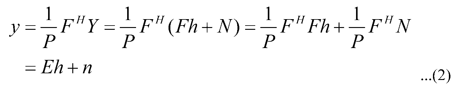
- the vector Y which is an estimated initial channel estimation value, is converted into the time domain through the IDFT based on Equation (2).
- Equation (2) has Hermitian Toeplitz characteristics in which the diagonal matrix elements are the same regardless of the pilot structure.
- the receiving apparatus After determining the CIR group and the CIR group weight in step 205, the receiving apparatus estimates a CIR of the determined CIR group using the group weight in step 207.
- the receiving apparatus may estimate the CIR in number of ways, a few of which will be described as follows.
- a second method for estimating a CIR includes determining a region of a power of a channel and repeating an MMSE process in a unit of the corresponding region.
- the first method and the second method address the shortcomings of the channel estimation scheme based on the general DFT, which suffers degradation in channel estimation.
- the first method for measuring the CIR of the corresponding region by determining only the region where the power of the channel exists determines the region where the powers of the channel are concentrated, estimates only a CIR of the determined region, and removes the other regions (i.e., allocates the value ‘0’), the other regions being regions of the noise and the interference.
- the receiving apparatus may estimate the CIR based on Equation (3).
- Equation (3) denotes an auto correlation matrix of the CIR vector h including the channel power values of the paths as its elements, and may be given by Equation (4).
- ⁇ denotes a threshold for eliminating the noise component and may be set to an appropriate value greater than 1 by taking into account the CIR interference component according to the guard band.
- ⁇ 2 denotes a power of the noise component
- I l denotes the l-th location of the power of the channel.
- Equation (3) Defining the group of the power of the channel as S and a number of estimated paths as M, Equation (3) can be approximated as shown in Equation (5).
- the second method for estimating the CIR by repeating the MMSE process per CIR group, which is a corresponding region unit, the receiving apparatus may carry out an MMSE process per CIR group based on Equation (7).
- the receiving apparatus puts the temporarily consecutive paths into one group, defines a set S based on Equation (6), and repeats the MMSE per group with respect to the set S.
- Equation (6) S g denotes a group index of the g-th temporarily successive CIR, M g denotes the number of CIR paths corresponding to the g-th group, and G denotes the number of groups.
- Equation (7) denotes a matrix E(M ⁇ M matrix), which selects a line and a column corresponding to the g-th group, and I denotes an index of the group where the power of the channel exists.
- Equation (7) produces the same result when the number of the paths of the groups is the same, regardless of the temporal location of the CIR group. Using this property, it is possible to determine the MMSE based on Equation (7), in advance, store the results, and apply the appropriate result in accordance with the situation, without having to repeat the MMSE process.
- the receiving apparatus cancels the interference by estimating the CIR in the descending order of the power of the groups having the power of the channel. That is, the receiving apparatus first estimates the CIR of a highest group and cancels the interference affecting other groups using the estimated value. Next, the receiving apparatus repeats the estimation by estimating the CIR of the group of a second highest power.
- the receiving apparatus may estimate the CIR in a descending order of channel power of the groups using the following algorithm.
- the receiving apparatus After canceling the interference of the estimated CIR in step 209, the receiving apparatus determines whether the CIR estimation is conducted on every group in step 211.
- the receiving apparatus estimates the CIR of the other CIR groups in step 205.
- the receiving apparatus Upon a determination that the CIR estimation of every group is completed in step 211, the receiving apparatus performs DFT on the estimated CIR in step 213.
- the receiving apparatus may arrange the determined CIR groups in a descending order of power, and estimate the CIR in the priority order of the arranged CIR groups or the CIR of the highest priority CIR group by repeating the CIR group determination in every CIR estimation per group.
- the receiving apparatus when estimating the CIR of the highest priority CIR group by repeating the CIR group determination in every CIR estimation per group, the receiving apparatus goes from step 211 to step 205, as is illustrated in FIG. 2. However, when estimating the CIR in the priority order of the arranged CIR groups, the receiving apparatus goes from 211 to step 207.
- FIG. 3 is a flowchart of a method for determining a CIR group at a receiving apparatus according to an embodiment of the present invention.
- step 301 the receiving apparatus measures power of a time-domain CIR converted through DFT.
- the receiving apparatus After determining an average of the measured CIR power in step 303, the receiving apparatus arranges the CIR groups based on the average of the CIR in step 305.
- the receiving apparatus arranges the CIR groups in a descending order of power of the groups having the power of the channel.
- step 307 the receiving apparatus determines the CIR group information and the weight of the corresponding group.
- the method proceeds to step 207 of FIG. 2 to estimate the CIR per CIR group.
- FIG. 4A and 4B depict a CIR group search at a receiving apparatus according to an embodiment of the present invention.
- FIG. 4A illustrates a CIR group search based on a Signal to Noise Ratio (SNR) in a Typical Urban (TU) channel.
- SNR Signal to Noise Ratio
- the CIR of the TU channel is divided largely into four CIR groups.
- the receiving apparatus estimates the channel of the initial pilot and conducts the IDFT, the CIR is distorted by the CIR dispersion and the noise of the guard band.
- FIG. 4B illustrates a CIR group searched using a low noise threshold.
- FIG. 4C illustrates the CIR group searched using a high noise threshold.
- FIG. 5 is a graph of the channel estimation performance of a receiving apparatus according to an embodiment of the present invention.
- the Mean Squared Error (MSE) performance is compared between the conventional receiving apparatus using the linear interpolation in the Pedestrian-A (PA) channel and the present receiving apparatus.
- the different receiving apparatuses represent receiving apparatuses of a localized MMSE scheme that measures CIR of a corresponding region by determining only a region of power of a channel, and receiving apparatuses of an iterative localized MMSE scheme that determines a region of power of a channel and estimates CIR by repeating an MMSE process in a unit of a corresponding region.
- the PA channel has a relatively small delay spread but features very close CIR paths.
- the conventional DFT-based receiving apparatus yields a relative good performance in a low SNR region by selectively processing a region of a channel, whereas its performance degrades in a high SNR region in a PA channel where adjacent paths are gathered, which is a shortcoming of an SIC scheme, compared to linear interpolation.
- the receiving apparatuses in accordance with the embodiments of the present invention exhibit excellent performance in every SNR region. That is, the receiving apparatus of the localized MMSE and the receiving apparatus of the iterative localized MMSE have substantially the same performance because they estimate the channel by searching one CIR group.
- FIG. 6 is another graph of a channel estimation performance of a receiving apparatus according to an embodiment of the present invention.
- MSE performance is compared between a conventional receiving apparatus using linear interpolation in a TU channel and a receiving apparatus in accordance with an embodiment of the present invention.
- the different receiving apparatuses represent the receiving apparatuses of a localized MMSE scheme that measures CIR of a corresponding region by determining only a region of power of a channel, and the receiving apparatuses of an iterative localized MMSE scheme that determines a region of power of a channel and estimates a CIR by repeating an MMSE process in a unit of a corresponding region.
- the conventional receiving apparatus reveals good performance relative to a PA channel, whereas an MSE is saturated in a high SNR region.
- the receiving apparatuses in accordance with the embodiments of the present invention demonstrate excellent performance in every SNR region.
- the performance difference between the iterative scheme and the localized MMSE scheme results from an approximation error in the localized MMSE repetition.
- the receiving apparatuses yield the performance difference merely in the relatively high SNR region, and produce the stabilized performance in most of the regions.
- channel estimation performance may be enhanced by addressing estimation performance degradation by a guard band, performance degradation in a low SNR region, and performance difference according to channel characteristics, which are some of the shortcomings of a conventional channel estimator.
Abstract
Description


Claims (12)
- An apparatus for estimating a channel in a mobile communication system, the apparatus comprising:a Channel Impulse Response (CIR) searcher (140) adapted to select a CIR group that is a region where a channel power exists;a CIR estimation part (120) adapted to estimate a CIR of a selected CIR group; anda Discrete Fourier Transform (DFT) (130) adapted to perform a DFT on an estimated CIR.
- The apparatus of claim 1, wherein the CIR estimation part estimates the CIR by one measuring a CIR of a corresponding region by determining only the region where the channel power exists, or by repeating a Minimum Mean-Square Error (MMSE) process in the unit of the corresponding region.
- The apparatus of claim 2, wherein the CIR estimation part determining only the region where the channel power exists based on:
 where S defines a group in which the channel power exists, and M denotes the number of estimated paths.
 - The apparatus of claim 2, wherein the CIR estimation repeats the MMSE process in the unit of the corresponding region based on:
 wheredenotes a matrix E(M×M matrix) that selects a line and a column corresponding to a g-th group, and I denotes an index of the group where the power of the channel exists.
- The apparatus of claim 1, wherein the CIR group searcher measures a power of a time-domain CIR converted through the DFT, determines an average of the power of the measured CIR, arranges CIR groups based on the average of the power of the measured CIR, and selects the region where the channel power exists.
- The apparatus of claim 5, wherein the CIR group searcher arranges the CIR groups in a descending order of the average of the power of the measured CIR.
- A method for estimating a channel in a mobile communication system, the method comprising:selecting a CIR group that is a region where a channel power exists;estimating a Channel Impulse Response (CIR) of a selected CIR group; andperforming a Discrete Fourier Transform (DFT) on an estimated CIR.
- The method of claim 7, wherein estimating the CIR comprises one of:measuring a CIR of a corresponding region by determining only the region where the channel power exists; andrepeating a Minimum Mean-Square Error (MMSE) process in a unit of the region.
- The method of claim 8, wherein measuring a CIR of a corresponding region by determining only the region where the channel power exists is performed using:
 where S defines a group in which the channel power exists, and M denotes a number of estimated paths.
 - The method of claim 8, wherein repeating the MMSE process in the unit of the corresponding region is performed using:
 wheredenotes a matrix E(M×M matrix) that selects a line and a column corresponding to a g-th group, and I denotes an index of the group where the power of the channel exists.
- The method of claim 7, wherein the selecting the region where the channel power exists comprises:measuring a power of a time-domain CIR converted through the DFT;determining an average of the power of the measured CIR; andarranging CIR groups based on the average of the power of the measured CIR.
- The method of claim 11, wherein arranging the CIR groups is conducted in a descending order of the average of the power of the measured CIR.
Priority Applications (3)
| Application Number | Priority Date | Filing Date | Title |
|---|---|---|---|
| JP2011516143A JP5645817B2 (en) | 2008-07-01 | 2009-07-01 | Channel estimation apparatus and method for mobile communication system |
| EP09773722.5A EP2291967B1 (en) | 2008-07-01 | 2009-07-01 | Apparatus and method for channel estimation in a mobile communication system |
| CN200980118312.XA CN102037698B (en) | 2008-07-01 | 2009-07-01 | The apparatus and method of channel estimating in mobile communication system |
Applications Claiming Priority (2)
| Application Number | Priority Date | Filing Date | Title |
|---|---|---|---|
| KR10-2008-0063394 | 2008-07-01 | ||
| KR1020080063394A KR101455273B1 (en) | 2008-07-01 | 2008-07-01 | Apparatus and method for channel estimation in mobile communication system |
Publications (2)
| Publication Number | Publication Date |
|---|---|
| WO2010002186A2 true WO2010002186A2 (en) | 2010-01-07 |
| WO2010002186A3 WO2010002186A3 (en) | 2010-04-01 |
Family
ID=41464314
Family Applications (1)
| Application Number | Title | Priority Date | Filing Date |
|---|---|---|---|
| PCT/KR2009/003579 WO2010002186A2 (en) | 2008-07-01 | 2009-07-01 | Apparatus and method for channel estimation in a mobile communication system |
Country Status (6)
| Country | Link |
|---|---|
| US (1) | US8045451B2 (en) |
| EP (1) | EP2291967B1 (en) |
| JP (1) | JP5645817B2 (en) |
| KR (1) | KR101455273B1 (en) |
| CN (1) | CN102037698B (en) |
| WO (1) | WO2010002186A2 (en) |
Families Citing this family (10)
| Publication number | Priority date | Publication date | Assignee | Title |
|---|---|---|---|---|
| KR101478203B1 (en) * | 2008-08-25 | 2014-12-31 | 삼성전자주식회사 | Apparatus and method for estimating channel in a mobile communication system |
| KR20100070751A (en) * | 2008-12-18 | 2010-06-28 | 한국전자통신연구원 | Channel estimating method in wireless communication system and apparatus thereof |
| JP5625719B2 (en) * | 2010-10-08 | 2014-11-19 | 富士通株式会社 | Radio receiving apparatus and radio receiving method |
| US9564980B2 (en) * | 2011-09-09 | 2017-02-07 | Samsung Electronics Co., Ltd. | Mobile telecommunication system with noise ratio estimation mechanism and method of operation thereof |
| WO2013037112A1 (en) | 2011-09-14 | 2013-03-21 | St-Ericsson Sa | Method and device for denoising in channel estimation, and corresponding computer program and computer readable storage medium |
| US9571260B2 (en) * | 2011-09-14 | 2017-02-14 | Optis Circuit Technology, Llc | Channel estimation method, channel estimation apparatus and communication device for CDMA systems |
| US8824527B2 (en) * | 2011-11-15 | 2014-09-02 | Acorn Technologies, Inc. | OFDM receiver with time domain channel estimation |
| CN103491031B (en) * | 2012-06-12 | 2018-03-02 | 中兴通讯股份有限公司 | Time domain CIR estimating circuits and method of estimation |
| US8897353B2 (en) * | 2013-03-15 | 2014-11-25 | Acorn Technologies, Inc. | Block time domain channel estimation in OFDM system |
| CN110300075B (en) * | 2019-04-30 | 2020-10-02 | 北京科技大学 | Wireless channel estimation method |
Citations (1)
| Publication number | Priority date | Publication date | Assignee | Title |
|---|---|---|---|---|
| US20060013326A1 (en) | 2004-07-13 | 2006-01-19 | Fujitsu Limited | Propagation path estimation method and apparatus |
Family Cites Families (9)
| Publication number | Priority date | Publication date | Assignee | Title |
|---|---|---|---|---|
| US7058134B2 (en) * | 2001-12-17 | 2006-06-06 | Intel Corporation | System and method for multiple signal carrier time domain channel estimation |
| KR100602745B1 (en) * | 2002-12-05 | 2006-07-20 | 텔레시스 와이어레스 인코포레이티드 | An Equalization apparatus for communication systems and method thereof |
| US7310394B2 (en) * | 2004-01-09 | 2007-12-18 | Wang Xiao-An | LMMSE-based RAKE receiver with channel tap assignment |
| JP4728227B2 (en) * | 2004-05-07 | 2011-07-20 | パナソニック株式会社 | OFDM receiving apparatus and OFDM receiving method |
| US8761312B2 (en) * | 2005-02-11 | 2014-06-24 | Qualcomm Incorporated | Selection of a thresholding parameter for channel estimation |
| KR100579526B1 (en) | 2005-02-18 | 2006-05-15 | 삼성전자주식회사 | Method for compensating sampling frequency offset and ofdm signal receiving apparatus thereof |
| US8428197B2 (en) * | 2006-06-01 | 2013-04-23 | Qualcomm Incorporated | Enhanced channel estimation for communication system receiver |
| KR101291684B1 (en) * | 2006-12-07 | 2013-08-01 | 삼성전자주식회사 | Method of channel estimation based on doubly adjacent windows and apparatus thereof |
| JP2009141514A (en) * | 2007-12-04 | 2009-06-25 | Nippon Telegr & Teleph Corp <Ntt> | Channel estimation apparatus and wireless communication system |
-
2008
- 2008-07-01 KR KR1020080063394A patent/KR101455273B1/en active IP Right Grant
-
2009
- 2009-07-01 WO PCT/KR2009/003579 patent/WO2010002186A2/en active Application Filing
- 2009-07-01 US US12/496,241 patent/US8045451B2/en active Active
- 2009-07-01 EP EP09773722.5A patent/EP2291967B1/en active Active
- 2009-07-01 JP JP2011516143A patent/JP5645817B2/en not_active Expired - Fee Related
- 2009-07-01 CN CN200980118312.XA patent/CN102037698B/en not_active Expired - Fee Related
Patent Citations (1)
| Publication number | Priority date | Publication date | Assignee | Title |
|---|---|---|---|---|
| US20060013326A1 (en) | 2004-07-13 | 2006-01-19 | Fujitsu Limited | Propagation path estimation method and apparatus |
Also Published As
| Publication number | Publication date |
|---|---|
| US8045451B2 (en) | 2011-10-25 |
| EP2291967A2 (en) | 2011-03-09 |
| KR101455273B1 (en) | 2014-10-27 |
| CN102037698B (en) | 2015-09-30 |
| WO2010002186A3 (en) | 2010-04-01 |
| EP2291967A4 (en) | 2017-03-22 |
| EP2291967B1 (en) | 2019-10-30 |
| US20100002574A1 (en) | 2010-01-07 |
| JP5645817B2 (en) | 2014-12-24 |
| JP2011526768A (en) | 2011-10-13 |
| KR20100003476A (en) | 2010-01-11 |
| CN102037698A (en) | 2011-04-27 |
Similar Documents
| Publication | Publication Date | Title |
|---|---|---|
| WO2010002186A2 (en) | Apparatus and method for channel estimation in a mobile communication system | |
| KR100949290B1 (en) | Apparatus and method for interference cancellation in broadband wireless access system | |
| WO2010050731A2 (en) | Dynamic cyclic prefix length change method and wireless system therefor | |
| WO2010140742A1 (en) | Method for providing information of access point selection | |
| WO2017150918A1 (en) | Filtering-based signal transmission and receiving methods and corresponding transmitter and receiver | |
| US7801084B2 (en) | Doppler frequency determination for mobile wireless devices | |
| WO2009134058A2 (en) | Apparatus and method for initialization of a scrambling sequence for a downlink reference signal in a wireless network | |
| WO2010131818A1 (en) | Inter-cell interference mitigation method using spatial covariance matrix estimation method for inter-cell interference mitigation of mimo antenna ofdm system | |
| WO2010126312A2 (en) | Method for relaying data in multi-hop cellular system | |
| EP2127282A2 (en) | Channel estimation with effective co-channel interference suppression | |
| WO2009104909A2 (en) | Apparatus and method for estimating i/q unbalance parameters in ofdm receiver | |
| WO2011049380A9 (en) | Signal detection apparatus and method in spatial multiplexing system | |
| WO2012121569A2 (en) | Downlink transmission/reception method and apparatus for mobile communication system | |
| WO2018088620A1 (en) | Method for compensating for distortion of subcarrier by using single-tap equalizer in ofdm system and apparatus therefor | |
| WO2016195328A1 (en) | Device and method for detecting filter bank multi carrier wave symbols in wireless communication system | |
| WO2011037362A2 (en) | Method for transmitting pilot signal in multi-carrier wireless transmission system | |
| WO2010101404A2 (en) | Multi-cell transmission diversity method and apparatus | |
| WO2019050378A1 (en) | Method and device for removing phase noise in wireless communication system | |
| WO2010058957A2 (en) | Method and apparatus for receiving data | |
| WO2009134008A1 (en) | Device and method for transmiting and receiving synchronization channel | |
| WO2017150832A1 (en) | Method for suppressing inter-subcarrier interference and noise signal, and orthogonal frequency division multiplexing receiver for performing same | |
| WO2021006666A1 (en) | Device and method for detecting interference between base stations in wireless communication system | |
| WO2010074522A2 (en) | Method and apparatus for receiving data | |
| CA2710674C (en) | Methods and apparatus for maximum ratio combining for duplicated signals in ofdma systems | |
| WO2022030986A1 (en) | Communication method and terminal for performing the same |
Legal Events
| Date | Code | Title | Description |
|---|---|---|---|
| WWE | Wipo information: entry into national phase |
Ref document number: 200980118312.X Country of ref document: CN |
|
| 121 | Ep: the epo has been informed by wipo that ep was designated in this application |
Ref document number: 09773722 Country of ref document: EP Kind code of ref document: A2 |
|
| WWE | Wipo information: entry into national phase |
Ref document number: 2009773722 Country of ref document: EP |
|
| ENP | Entry into the national phase |
Ref document number: 2011516143 Country of ref document: JP Kind code of ref document: A |
|
| WWE | Wipo information: entry into national phase |
Ref document number: 5014/KOLNP/2010 Country of ref document: IN |
|
| NENP | Non-entry into the national phase |
Ref country code: DE |