WO2009157159A1 - 記録媒体、再生装置、集積回路、再生方法、プログラム - Google Patents
記録媒体、再生装置、集積回路、再生方法、プログラム Download PDFInfo
- Publication number
- WO2009157159A1 WO2009157159A1 PCT/JP2009/002775 JP2009002775W WO2009157159A1 WO 2009157159 A1 WO2009157159 A1 WO 2009157159A1 JP 2009002775 W JP2009002775 W JP 2009002775W WO 2009157159 A1 WO2009157159 A1 WO 2009157159A1
- Authority
- WO
- WIPO (PCT)
- Prior art keywords
- graphics
- playback
- application
- content
- view
- Prior art date
Links
- 238000000034 method Methods 0.000 title claims description 75
- 230000015654 memory Effects 0.000 claims abstract description 106
- 238000009877 rendering Methods 0.000 claims description 4
- 238000007726 management method Methods 0.000 description 85
- 239000004065 semiconductor Substances 0.000 description 50
- 239000000872 buffer Substances 0.000 description 44
- 230000006870 function Effects 0.000 description 32
- 238000012545 processing Methods 0.000 description 31
- 238000010586 diagram Methods 0.000 description 27
- 238000009826 distribution Methods 0.000 description 25
- 230000008569 process Effects 0.000 description 25
- 238000003860 storage Methods 0.000 description 18
- 239000004973 liquid crystal related substance Substances 0.000 description 16
- 230000003287 optical effect Effects 0.000 description 14
- 238000001824 photoionisation detection Methods 0.000 description 14
- 238000012546 transfer Methods 0.000 description 9
- 238000006243 chemical reaction Methods 0.000 description 7
- 230000003068 static effect Effects 0.000 description 7
- 230000005540 biological transmission Effects 0.000 description 6
- 238000004458 analytical method Methods 0.000 description 5
- 238000013461 design Methods 0.000 description 5
- 238000005516 engineering process Methods 0.000 description 5
- 230000006872 improvement Effects 0.000 description 5
- 238000004519 manufacturing process Methods 0.000 description 5
- 230000004044 response Effects 0.000 description 5
- 230000004913 activation Effects 0.000 description 4
- 230000008859 change Effects 0.000 description 4
- 238000011161 development Methods 0.000 description 4
- 230000018109 developmental process Effects 0.000 description 4
- 230000002123 temporal effect Effects 0.000 description 4
- 230000007704 transition Effects 0.000 description 4
- 206010047571 Visual impairment Diseases 0.000 description 3
- 238000009825 accumulation Methods 0.000 description 3
- 238000007906 compression Methods 0.000 description 3
- 230000006835 compression Effects 0.000 description 3
- 210000003128 head Anatomy 0.000 description 3
- 230000007246 mechanism Effects 0.000 description 3
- 230000001172 regenerating effect Effects 0.000 description 3
- 230000011664 signaling Effects 0.000 description 3
- 230000015572 biosynthetic process Effects 0.000 description 2
- 238000005206 flow analysis Methods 0.000 description 2
- 238000005457 optimization Methods 0.000 description 2
- 230000008520 organization Effects 0.000 description 2
- 230000002093 peripheral effect Effects 0.000 description 2
- 238000011069 regeneration method Methods 0.000 description 2
- 238000013468 resource allocation Methods 0.000 description 2
- 238000000926 separation method Methods 0.000 description 2
- 239000000758 substrate Substances 0.000 description 2
- 230000001360 synchronised effect Effects 0.000 description 2
- LZDYZEGISBDSDP-UHFFFAOYSA-N 2-(1-ethylaziridin-1-ium-1-yl)ethanol Chemical compound OCC[N+]1(CC)CC1 LZDYZEGISBDSDP-UHFFFAOYSA-N 0.000 description 1
- 101100137868 Solanum lycopersicum PAD1 gene Proteins 0.000 description 1
- 206010053615 Thermal burn Diseases 0.000 description 1
- 230000002159 abnormal effect Effects 0.000 description 1
- 230000001174 ascending effect Effects 0.000 description 1
- 230000033228 biological regulation Effects 0.000 description 1
- 210000004556 brain Anatomy 0.000 description 1
- 230000003139 buffering effect Effects 0.000 description 1
- 239000003990 capacitor Substances 0.000 description 1
- 238000012790 confirmation Methods 0.000 description 1
- 238000012937 correction Methods 0.000 description 1
- 230000003247 decreasing effect Effects 0.000 description 1
- 238000009472 formulation Methods 0.000 description 1
- 238000010348 incorporation Methods 0.000 description 1
- 230000010354 integration Effects 0.000 description 1
- 230000002452 interceptive effect Effects 0.000 description 1
- NUHSROFQTUXZQQ-UHFFFAOYSA-N isopentenyl diphosphate Chemical compound CC(=C)CCO[P@](O)(=O)OP(O)(O)=O NUHSROFQTUXZQQ-UHFFFAOYSA-N 0.000 description 1
- 230000009191 jumping Effects 0.000 description 1
- 238000013507 mapping Methods 0.000 description 1
- 239000000203 mixture Substances 0.000 description 1
- 238000012544 monitoring process Methods 0.000 description 1
- 238000004806 packaging method and process Methods 0.000 description 1
- 238000003825 pressing Methods 0.000 description 1
- 230000008929 regeneration Effects 0.000 description 1
- 239000011347 resin Substances 0.000 description 1
- 229920005989 resin Polymers 0.000 description 1
- 230000004043 responsiveness Effects 0.000 description 1
- 239000007787 solid Substances 0.000 description 1
- 230000002269 spontaneous effect Effects 0.000 description 1
- 238000003786 synthesis reaction Methods 0.000 description 1
- 230000002194 synthesizing effect Effects 0.000 description 1
- 238000013519 translation Methods 0.000 description 1
- 238000002834 transmittance Methods 0.000 description 1
Images


Classifications
-
- H—ELECTRICITY
- H04—ELECTRIC COMMUNICATION TECHNIQUE
- H04N—PICTORIAL COMMUNICATION, e.g. TELEVISION
- H04N5/00—Details of television systems
- H04N5/76—Television signal recording
- H04N5/84—Television signal recording using optical recording
- H04N5/85—Television signal recording using optical recording on discs or drums
-
- G—PHYSICS
- G09—EDUCATION; CRYPTOGRAPHY; DISPLAY; ADVERTISING; SEALS
- G09G—ARRANGEMENTS OR CIRCUITS FOR CONTROL OF INDICATING DEVICES USING STATIC MEANS TO PRESENT VARIABLE INFORMATION
- G09G3/00—Control arrangements or circuits, of interest only in connection with visual indicators other than cathode-ray tubes
- G09G3/001—Control arrangements or circuits, of interest only in connection with visual indicators other than cathode-ray tubes using specific devices not provided for in groups G09G3/02 - G09G3/36, e.g. using an intermediate record carrier such as a film slide; Projection systems; Display of non-alphanumerical information, solely or in combination with alphanumerical information, e.g. digital display on projected diapositive as background
- G09G3/003—Control arrangements or circuits, of interest only in connection with visual indicators other than cathode-ray tubes using specific devices not provided for in groups G09G3/02 - G09G3/36, e.g. using an intermediate record carrier such as a film slide; Projection systems; Display of non-alphanumerical information, solely or in combination with alphanumerical information, e.g. digital display on projected diapositive as background to produce spatial visual effects
-
- G—PHYSICS
- G11—INFORMATION STORAGE
- G11B—INFORMATION STORAGE BASED ON RELATIVE MOVEMENT BETWEEN RECORD CARRIER AND TRANSDUCER
- G11B27/00—Editing; Indexing; Addressing; Timing or synchronising; Monitoring; Measuring tape travel
- G11B27/10—Indexing; Addressing; Timing or synchronising; Measuring tape travel
- G11B27/19—Indexing; Addressing; Timing or synchronising; Measuring tape travel by using information detectable on the record carrier
- G11B27/28—Indexing; Addressing; Timing or synchronising; Measuring tape travel by using information detectable on the record carrier by using information signals recorded by the same method as the main recording
- G11B27/32—Indexing; Addressing; Timing or synchronising; Measuring tape travel by using information detectable on the record carrier by using information signals recorded by the same method as the main recording on separate auxiliary tracks of the same or an auxiliary record carrier
- G11B27/327—Table of contents
- G11B27/329—Table of contents on a disc [VTOC]
-
- G—PHYSICS
- G11—INFORMATION STORAGE
- G11B—INFORMATION STORAGE BASED ON RELATIVE MOVEMENT BETWEEN RECORD CARRIER AND TRANSDUCER
- G11B27/00—Editing; Indexing; Addressing; Timing or synchronising; Monitoring; Measuring tape travel
- G11B27/10—Indexing; Addressing; Timing or synchronising; Measuring tape travel
- G11B27/34—Indicating arrangements
-
- H—ELECTRICITY
- H04—ELECTRIC COMMUNICATION TECHNIQUE
- H04N—PICTORIAL COMMUNICATION, e.g. TELEVISION
- H04N13/00—Stereoscopic video systems; Multi-view video systems; Details thereof
- H04N13/10—Processing, recording or transmission of stereoscopic or multi-view image signals
- H04N13/189—Recording image signals; Reproducing recorded image signals
-
- H—ELECTRICITY
- H04—ELECTRIC COMMUNICATION TECHNIQUE
- H04N—PICTORIAL COMMUNICATION, e.g. TELEVISION
- H04N13/00—Stereoscopic video systems; Multi-view video systems; Details thereof
- H04N13/30—Image reproducers
- H04N13/332—Displays for viewing with the aid of special glasses or head-mounted displays [HMD]
- H04N13/341—Displays for viewing with the aid of special glasses or head-mounted displays [HMD] using temporal multiplexing
-
- G—PHYSICS
- G09—EDUCATION; CRYPTOGRAPHY; DISPLAY; ADVERTISING; SEALS
- G09G—ARRANGEMENTS OR CIRCUITS FOR CONTROL OF INDICATING DEVICES USING STATIC MEANS TO PRESENT VARIABLE INFORMATION
- G09G2370/00—Aspects of data communication
- G09G2370/10—Use of a protocol of communication by packets in interfaces along the display data pipeline
-
- G—PHYSICS
- G09—EDUCATION; CRYPTOGRAPHY; DISPLAY; ADVERTISING; SEALS
- G09G—ARRANGEMENTS OR CIRCUITS FOR CONTROL OF INDICATING DEVICES USING STATIC MEANS TO PRESENT VARIABLE INFORMATION
- G09G5/00—Control arrangements or circuits for visual indicators common to cathode-ray tube indicators and other visual indicators
- G09G5/003—Details of a display terminal, the details relating to the control arrangement of the display terminal and to the interfaces thereto
- G09G5/006—Details of the interface to the display terminal
-
- G—PHYSICS
- G11—INFORMATION STORAGE
- G11B—INFORMATION STORAGE BASED ON RELATIVE MOVEMENT BETWEEN RECORD CARRIER AND TRANSDUCER
- G11B2220/00—Record carriers by type
- G11B2220/20—Disc-shaped record carriers
- G11B2220/21—Disc-shaped record carriers characterised in that the disc is of read-only, rewritable, or recordable type
- G11B2220/213—Read-only discs
-
- G—PHYSICS
- G11—INFORMATION STORAGE
- G11B—INFORMATION STORAGE BASED ON RELATIVE MOVEMENT BETWEEN RECORD CARRIER AND TRANSDUCER
- G11B2220/00—Record carriers by type
- G11B2220/20—Disc-shaped record carriers
- G11B2220/23—Disc-shaped record carriers characterised in that the disc has a specific layer structure
- G11B2220/235—Multilayer discs, i.e. multiple recording layers accessed from the same side
-
- G—PHYSICS
- G11—INFORMATION STORAGE
- G11B—INFORMATION STORAGE BASED ON RELATIVE MOVEMENT BETWEEN RECORD CARRIER AND TRANSDUCER
- G11B2220/00—Record carriers by type
- G11B2220/20—Disc-shaped record carriers
- G11B2220/25—Disc-shaped record carriers characterised in that the disc is based on a specific recording technology
- G11B2220/2537—Optical discs
- G11B2220/2541—Blu-ray discs; Blue laser DVR discs
-
- H—ELECTRICITY
- H04—ELECTRIC COMMUNICATION TECHNIQUE
- H04N—PICTORIAL COMMUNICATION, e.g. TELEVISION
- H04N5/00—Details of television systems
- H04N5/76—Television signal recording
- H04N5/78—Television signal recording using magnetic recording
- H04N5/781—Television signal recording using magnetic recording on disks or drums
-
- H—ELECTRICITY
- H04—ELECTRIC COMMUNICATION TECHNIQUE
- H04N—PICTORIAL COMMUNICATION, e.g. TELEVISION
- H04N5/00—Details of television systems
- H04N5/76—Television signal recording
- H04N5/907—Television signal recording using static stores, e.g. storage tubes or semiconductor memories
-
- H—ELECTRICITY
- H04—ELECTRIC COMMUNICATION TECHNIQUE
- H04N—PICTORIAL COMMUNICATION, e.g. TELEVISION
- H04N9/00—Details of colour television systems
- H04N9/79—Processing of colour television signals in connection with recording
- H04N9/7921—Processing of colour television signals in connection with recording for more than one processing mode
-
- H—ELECTRICITY
- H04—ELECTRIC COMMUNICATION TECHNIQUE
- H04N—PICTORIAL COMMUNICATION, e.g. TELEVISION
- H04N9/00—Details of colour television systems
- H04N9/79—Processing of colour television signals in connection with recording
- H04N9/80—Transformation of the television signal for recording, e.g. modulation, frequency changing; Inverse transformation for playback
- H04N9/82—Transformation of the television signal for recording, e.g. modulation, frequency changing; Inverse transformation for playback the individual colour picture signal components being recorded simultaneously only
- H04N9/8205—Transformation of the television signal for recording, e.g. modulation, frequency changing; Inverse transformation for playback the individual colour picture signal components being recorded simultaneously only involving the multiplexing of an additional signal and the colour video signal
- H04N9/8227—Transformation of the television signal for recording, e.g. modulation, frequency changing; Inverse transformation for playback the individual colour picture signal components being recorded simultaneously only involving the multiplexing of an additional signal and the colour video signal the additional signal being at least another television signal
Definitions
- the present invention belongs to the technical field of stereoscopic reproduction.
- the time-separation method is a method in which a left-view video and a right-view video are alternately displayed in the time axis direction, and the left and right scenes are superimposed in the brain by the afterimage reaction of the eyes to be recognized as a stereoscopic video. .
- the reproduction apparatus described in Japanese Patent Application Laid-Open No. 2004-109330 includes key input means and display switching means for flat display (2D) and stereoscopic display (3D), and according to key input by the key input means, Switching between planar display and stereoscopic display by the display switching means.
- the memory size required for that will double, and this will be the memory that is implemented in the playback device, along with the video plane for storing the video stream. Most of the device area will be occupied by plain memory.
- the image quality for HDTV requires a resolution of 1920 x 1080, and if the bit length of the index per pixel is 32 bits, the total capacity of the graphics plane is 8 MB ( ⁇ 1920 x 1080 x 32) become. If this graphics plane is assigned to each of the right view and left view for stereoscopic viewing, 16 Mbytes of memory will be consumed, putting pressure on resources.
- the switching of the stereoscopic vision described in the prior art documents described above is for switching whether the user realizes the stereoscopic vision with a positive intention or the planar vision, and even if such a technique is applied, As long as the user does not actively switch the stereoscopic reproduction to the planar reproduction, the plane memory for the stereoscopic view remains secured. Therefore, the invention described in the above document solves the technical problem as described above. It does not bring
- An object of the present invention is to provide a recording medium capable of avoiding a lack of resources when reproducing a plurality of contents, some of which are stereoscopic content and the rest are planar content. is there.
- a playback apparatus is a recording medium on which a plurality of contents including video data, a management object, and an application are recorded, and the video data included in the contents includes: There are ones constituting a planar video and ones constituting a stereoscopic video, and the management object included in each of the plurality of contents includes an application management table and configuration information, and the application management table is When content including the application management table becomes a playback target, among the applications included in the playback target content, along with the playback of the video data included in the playback target content, the application to be started is set in the playback device.
- the configuration information is generated so that a graphics plane having a scale corresponding to the resolution of the video data to be played is secured on a memory device included in the playback device. It includes information and a flag for instructing the apparatus, and the flag indicates whether or not a plurality of graphics planes need to be secured on the memory device in order to realize stereoscopic viewing of graphics.
- the flag in the configuration information as described above indicates whether or not a plurality of graphics planes need to be secured in order to realize graphics stereoscopic viewing. In doing so, the scale of the graphics plane to be secured will return to one. Even if a graphics plane is added for stereoscopic content, the additional graphics plane remains secured, and the free space in the memory is not subjected to pressure. Therefore, the operation of the application can be stabilized.
- a BD-ROM that allows only one of the many contents to be viewed in stereo and the others to be played in plan view can be played back, immediately after the playback of the stereoscopic content, Multiple graphics planes for viewing can be released.
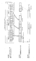
- FIG. 3 is a diagram illustrating a correspondence relationship between a physical unit of a BD-ROM and source packets that form one file extent.
- FIG. 3 is a diagram illustrating a plurality of numerical ranges that can be taken by a packet ID of a TS packet and a PES stream type of a TS packet having a packet ID in each numerical range in association with each other.
- positioning It is a figure which shows an example of the internal structure of the base view stream for stereoscopic vision, and the enhanced view stream. It is a figure which shows what kind of image
- It is a figure which shows the data structure of play list information. It is a figure which shows the internal structure of a subpath information table. This indicates what playback section is defined for the left view and right view. It is a figure which shows the internal structure of the extension data in play list information. It is a figure which shows the internal structure of a video stream number table. It is a figure which shows the internal structure of a JAR archive file. It is a figure which shows the internal structure of a BD-J object. It is a figure which shows the internal structure of a GUI management table. The correspondence between the resolution of the video plane and the graphics plane is shown. The settings of the GUI management table and the contents of the memory are shown. A graphics plane secured by resolution code “2”, “3” is shown.
- FIG. 3 is a diagram showing components in a front end unit 105 to a back end unit 108. It is a figure which shows the software layer model in a reproducing
- the Index.bdmv and BD-J objects are drawn on the left side, and the software layer model is drawn on the right side.
- FIG. 2 is a diagram in which a BD-J application existing on a software layer model, a video plane, and a graphics plane are drawn together.
- 4 is a flowchart showing a processing procedure performed by a module manager 42. It is a flowchart which shows the reproduction
- FIG. 1 is a diagram showing a form of usage of a recording medium and a playback device.
- a BD-ROM 101 and a playback device 102 which are examples of a recording medium constitute a home theater system together with a television 103 and a liquid crystal shutter goggles 104 and are used by a user.
- BD-ROM 101 supplies, for example, a movie work to the home theater system.
- the playback device 102 is connected to the television 103 and plays back the BD-ROM 101.
- a remote controller is attached to the playback device 102.
- This remote control is a device that accepts operations on the hierarchical GUI from the user. For accepting such operations, the remote control uses a menu key for calling a menu constituting the GUI and an arrow for moving the focus of the GUI component constituting the menu It includes a key, a determination key for performing a confirmation operation on the GUI components constituting the menu, a return key for returning the hierarchical menu to a higher level, and a numerical key.
- the television 103 provides an interactive operation environment to the user by displaying a playback image of a movie work or displaying a menu or the like.
- the liquid crystal shutter goggles 104 are composed of a liquid crystal shutter and a control unit, and realize stereoscopic viewing using parallax in both eyes of the user.
- the liquid crystal shutter of the liquid crystal shutter goggles 104 is a shutter using a liquid crystal lens having a property that the light transmittance is changed by changing an applied voltage.
- the control unit of the liquid crystal shutter goggles 104 receives the synchronization signal for switching the output of the right-view image and the left-view image sent from the playback device, and in accordance with this synchronization signal, the first state and the second state Switch.
- FIG. 1B shows the first state.
- the first state is a state in which the applied voltage is adjusted so that the liquid crystal lens corresponding to the right view does not transmit light, and the applied voltage is adjusted so that the liquid crystal lens corresponding to the left view transmits light. In this state, the left-view image is used for viewing.
- FIG. 1 (c) shows the second state.
- the second state is a state in which the applied voltage is adjusted so that the liquid crystal lens corresponding to the right view transmits light, and the applied voltage is adjusted so that the liquid crystal lens corresponding to the left view does not transmit light.
- the liquid crystal shutter goggles can provide a right-view image for viewing.
- the short time interval may be a time enough to give an illusion that a person looks three-dimensional by the switching display described above. This completes the description of the home theater system. Next, details of the BD-ROM will be described.
- FIG. 2 shows an internal configuration of an optical disc, more specifically a BD-ROM, which is an example of a recording medium described in the present embodiment.
- the first level shows a BD-ROM which is a multilayered optical disc
- the second level shows a spiral track extending on each recording layer extended in the horizontal direction. This spiral track is treated as one continuous recording area.
- the recording area includes a lead-in located on the innermost circumference, a lead-out located on the innermost circumference, a recording area of the first recording layer, a recording area of the second recording layer, and a recording area of the third recording layer existing therebetween. Consists of
- the third row shows the file system area in BD-ROM.
- the file system area is composed of a “volume management area” and a “logical address space”.
- the “volume management area” stores file system management information for handling the recording area of the first recording layer, the recording area of the second recording layer, and the recording area of the third recording layer as one continuous file system space. It is an area.
- Logical address space is an address space indicated by a logical block number (LBN) in which sectors continue. That is, the recording area of the first recording layer, the recording area of the second recording layer, and the recording area of the third recording layer in the second stage constitute one continuous logical address space.
- LBN logical block number
- the fourth row shows area allocation in the logical address space of the file system management area.
- a non-AV data recording area exists on the inner circumference side.
- An AV data recording area exists immediately after the non-AV data recording area.
- the fifth row shows extents recorded in these non-AV data recording area and AV data recording area.
- extents EXT, EXT, EXT... In the figure
- non-AV data recording area there are extents (EXT, EXT, EXT... In the figure) constituting files other than AV files.
- Fig. 3 is a diagram showing the application format of BD-ROM.
- BDMV directory is a directory in which data such as AV contents and management information handled by the BD-ROM is recorded. Under the BDMV directory, there are five subdirectories called “JAR directory”, “BDJO directory”, “PLAYLIST directory”, “CLIPINF directory”, and “STREAM directory”. In the BDMV directory, “index.bdmv” ”And“ MovieObject.bdmv ”are arranged.
- index.bdmv is management information relating to the entire BD-ROM, and after the disc is inserted into the playback device, the index.bdmv is read first so that the disc is uniquely recognized by the playback device.
- index.bdmv indicates the correspondence between the title numbers of a plurality of titles that can be played back on the BD-ROM and BD-J objects that define individual titles.
- “MovieObject.bdmv” stores one or more movie objects.
- a movie object is a management object that defines the control procedure to be performed by the playback device in an operation mode (HDMV mode) mainly controlled by a command interpreter.
- HDMV mode operation mode
- One or more commands, GUI menu calls, and title calls can be used by the user.
- JAR directory is a directory in which JAR files corresponding to archive files are placed.
- An archive file is a file obtained by combining one or more class files, one or more data files, etc. into one.
- One or more class files, one or more data files, and the like can be combined into one by, for example, an archiver (not shown).
- Java (registered trademark) archive file will be described as an example of an archive file.
- BD-J mode mainly controlled by a Java virtual machine that is a byte code interpreter provided in the playback device
- the control procedure to be performed by the playback device is specified.
- a file storing a JAR file is identified by a 5-digit number zzzzz and an extension jar.
- the “BDJO directory” is a file that stores a management object (BDJ object) that defines the control procedure to be performed by the playback device in an operation mode (BD-J mode) mainly controlled by a Java virtual machine that is a bytecode interpreter.
- BDJ object management object
- a file storing a BDJ object is identified by a 5-digit number zzzzz and an extension bdjo.
- a file storing playlist information including main path information for specifying a playback section for the base view stream and sub-path information for specifying a playback section for the enhanced view stream is arranged.
- the file storing the playlist information is identified by a 5-digit identification number “yyyyy” and an extension “mpls”.
- the base view stream is a video stream that constitutes a left view or a right view, and can realize planar display.
- a video stream that constitutes a right view or a left view and is not a base view stream is referred to as an “enhanced view stream”.
- the picture data constituting the enhanced view stream is compression-encoded based on the frame correlation with the picture data constituting the base view stream.
- MVC Multiview Video Coding
- CLIPINF directory is a directory in which files (clip information files) storing clip information are placed.
- the clip information file is identified by a 5-digit identification number “xxxxx” and an extension “clpi”. Inside the clip information file, there are entry maps corresponding to the left-view video stream and the right-view video stream.
- Extents that make up the files in the above directories are recorded in the non-AV data area.
- “STREAM directory” is a directory in which an AV clip file storing a stereoscopic video stream and an AV clip file storing a stereoscopic video stream are arranged.
- a file storing a planar video stream is identified by a 5-digit identification number “xxxxx” and an extension “m2ts”.
- a file storing a stereoscopic video stream is identified by a 5-digit identification number “xxxxx” and an extension “ilts”.
- the extents constituting the base view stream file stored in the STREAM directory and the extents constituting the enhanced view stream file to be stored in the STREAM directory are recorded in the AV data recording area.
- FIG. 4 shows a process through which each source packet constituting the left view stream and the right view stream is written in the AV data area.
- the first level in the figure shows TS packets that constitute a base view stream or an enhanced view stream.
- TS_extra_header (hatched portion in the figure) as shown in the second row to become a source packet with a length of 192 bytes.
- This TS_extra_header includes Arrival_Time_Stamp indicating the decoder input time information of the TS packet.
- the source packets that make up the base view stream and the enhanced view stream form one or more “ATC sequences” in the third stage.
- the “ATC sequence” is an array of source packets constituting the time axis of the ATS, and means that there is no discontinuity (no arrival time-base discontinutiy) in the Arrival_Time_Clock referenced by the Arrival_Time_Stamp.
- a source packet sequence having continuity in the Arrival_Time_Clock referenced by the Arrival_Time_Stamp is referred to as an “ATC sequence”.
- ATS is added to the head of the TS packet as follows, and indicates the transfer time to the decoder.
- the ATC sequence becomes an AV clip and is recorded on the recording layer with the file name xxxxx.m2ts.
- Such an AV clip is divided into one or more file extents and recorded in an area on each recording layer, like a normal computer file.
- the third row shows the AV clip
- the fourth row schematically shows how the AV clip is recorded on each recording layer.
- Each file extent constituting the file in the fourth stage has a data length equal to or larger than a predetermined size (this size is referred to as S_EXT).
- FIG. 5 shows a physical unit of BD-ROM and one file. It is a figure which shows the correspondence with the source packet which comprises an extent.
- a plurality of sectors are formed in the AV file recording area of the BD-ROM.
- the source packets constituting the file extent are grouped every 32 and written into three consecutive sectors.
- error correction codes are added in units of 32 sectors, and an ECC block is configured.
- the playback device can obtain 32 complete source packets as long as the BD-ROM is accessed in units of Aligned Unit. The above is the process of writing the AV clip to the BD-ROM.
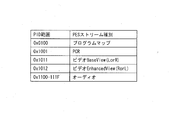
- FIG. 6 is a diagram showing a plurality of numerical ranges that can be taken by the packet ID of the TS packet and the PES stream types of the TS packets having packet IDs in the respective numerical ranges in association with each other.
- TS packets having a packet ID of 0x0100 constitute a program map (Program_map), and TS packets having a packet ID of 0x1001 constitute a program clock reference (PCR).
- Program_map program map
- PCR program clock reference
- TS packets with a packet ID of 0x1011 constitute a base view stream
- Ox1012 TS packets constitute an enhanced view stream
- TS packets with a packet ID of 0x1100-11F constitute an audio stream.
- FIG. 7 is a diagram illustrating an example of an interleaved arrangement.
- the interleaved arrangement means that the extents that make up the base view and enhanced view are recorded with the regularity of "base view”, “enhanced view”, “base view”, “enhanced view” ... It is that you are.
- the first row shows the AV file
- the second row shows the extents EXT_L [i], EXT_L [i + 1], EXT_R [i], and EXT_R [i + 1] constituting the AV file.
- the third level shows the source packet sequence belonging to each extent
- the fourth level shows the sector sequence in the recording layer.
- variables i and i + 1 in parentheses indicate the number of extents to be reproduced.
- Dashed arrows h1, h2, h3, and h4 indicate the belonging relationship that the extents EXT_L [i] and EXT_L [i + 1] belong to either the base view stream or the enhanced view stream.
- the belonging relationship indicated by the arrows h1 and h2 it can be seen that the extents EXT_L [i] and EXT_L [i + 1] belong to the base view stream.
- the arrows h3 and h4 it can be seen that the extents EXT_R [i] and EXT_R [i + 1] belong to the enhanced view stream.
- SEXT_L and SEXT_R are alternately read out into two buffers, a right-view read buffer and a left-view read buffer, and provided to a video decoder in the playback apparatus.
- the sizes of SEXT_L and SEXT_R need to be determined in consideration of the time required for buffering the right-view read buffer and the left-view read buffer.
- the transfer rate to the read buffer for right view is Rmax1
- Right-view read buffer Rmax1 x "Time to fill left-view read buffer with jump”
- the capacity of the read buffer for right view must be determined so as to satisfy the relationship.
- jumping is synonymous with disc seeking. This is because the continuous area that can be secured for recording in the BD-ROM is limited, and the base view stream and the enhanced view stream are not necessarily recorded side by side, and may be recorded in a skipped area. It is.
- TS packet accumulation in the left-view read buffer is performed at a transfer rate of Rud-Rmax2. This means the difference between the output rate Rmax2 from the left-view read buffer and the input rate Rud to the left-view read buffer. Then, the time for filling the left-view read buffer becomes RB2 / (Rud-Rmax2).
- the size of the view read buffer RB1 is RB1 ⁇ Rmax1 ⁇ ⁇ 2 ⁇ Tjump + RB2 / (Rud-Rmax2) ⁇ become.
- the left view read buffer capacity RB2 is calculated.
- RB2 ⁇ Rmax2 ⁇ ⁇ 2 ⁇ Tjump + RB1 / (Rud-Rmax1) ⁇ become.
- the specific values of the memory size of the right-view read buffer and the left-view read buffer are 1.5 Mbytes or less.
- the extent sizes SEXT_R and SEXT_L are the right-view read buffer and the left-view read. It is set to the same size as the buffer size or approximately the same size. This completes the description of how the base view stream and the enhanced view stream are recorded. Next, the internal configuration of the base view stream and the enhanced view stream will be described.
- FIG. 8 is a diagram illustrating an example of an internal configuration of a base view stream and an enhanced view stream for stereoscopic viewing.
- the base view stream and the enhanced view stream include, for example, picture data.
- picture data There are a plurality of types of picture data, including picture data such as I picture, P picture, and B picture.
- An I picture is picture data for one screen.
- a P picture is picture data indicating a difference from a reference I picture.
- a B picture is picture data generated by a standard I picture and P picture.
- the second level in the figure shows the internal structure of the base view stream.
- This stream includes picture data of picture data I1, P2, Br3, Br4, P5, Br6, Br7, and P9.
- the picture data are decoded according to DTS (decoding time stamp: information indicating the start time of decoding by the decoder).
- the first level shows a left view image.
- the decoded picture data I1, P2, Br3, Br4, P5, Br6, Br7, P9 are played in the order of I1, Br3, Br4, P2, Br6, Br7, P5 according to PTS, and the left view The image will be played back.
- the fourth level shows the internal structure of the enhanced view stream.
- This secondary video stream includes picture data P1, P2, B3, B4, P5, B6, B7, and P8. These picture data are decoded according to DTS.
- the third row shows a right view image.
- the decoded picture data P1, P2, B3, B4, P5, B6, B7, and P8 are converted into P1, B3, B4, P2, and P2 according to PTS (presentation time stamp: information indicating video / audio presentation time). By reproducing in the order of B6, B7, and P5, the right-view image is reproduced.
- the fifth row shows how the state of the liquid crystal shutter goggles 104 is changed. As shown in the fifth row, the right-view liquid crystal shutter is closed when viewing the left-view video, and the left-view liquid crystal shutter is closed when viewing the right-view video.
- These primary video stream and secondary video stream are compressed by inter-picture predictive coding using inter-view redundancy in addition to inter-picture predictive coding using temporal redundancy.
- the pictures in the enhanced view stream are compressed with reference to the pictures at the same display time in the base view stream.
- the first P picture of the enhanced view stream refers to the I picture of the base view stream
- the B picture of the enhanced view stream refers to the Br picture of the base view stream
- the second P picture of the enhanced view stream is Referring to the P picture of the base view stream.
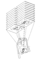
- FIG. 9 is a diagram showing what video is used for reproduction by switching the light transmission / shading of goggles according to the timing of FIG.
- the frame display period is 1/24 second, and if the translucency / shading of the right view and the left view in the goggles is changed every 1/48 seconds, the pictures of the right view and the left view are alternately displayed. Will appear.
- the left view image and the right view image shown in FIG. 9 schematically show that the orientation and position of the face of the person appearing in the image are slightly shifted between the left view image and the right view image. (Incidentally, deviations in the orientation and position of a person's face in FIGS. 9 and 10 are schematic.)
- FIG. 10 is a diagram showing a stereoscopic image formed by the afterimage reaction of the eyes.
- FIG. 11 is a diagram illustrating an example of a clip information file.
- the clip information file is management information of the AV clip as shown in the figure, has a one-to-one correspondence with the AV clip, and includes a stream attribute table and an entry map table.
- the lead line zh1 shows a close-up of the internal structure of the stream attribute table.
- attribute information about each stream included in the AV clip is registered for each PID.
- the attribute information has different information for each base view stream and enhanced view stream.
- the entry map is a table showing the correspondence between the source packet number of an arbitrary source packet and the PTS on the STC time axis among the STC time axes specified by using a certain packet ID.
- the STC time axis is an MPEG2-TS time axis representing decoding time and display time.
- a group of one source packet in which there is no system time-base discontinuity of STC (System Time Clock) that is the system reference time of the AV stream is called an “STC sequence”.
- FIG. 12A shows the internal structure of the entry map table.
- a lead line eh1 shows a close-up of the internal structure of the entry map table.
- information including a pair of PTS and SPN is called an “entry point”.
- the entry point is information in which a combination of PTS and SPN is associated with a display method flag (is_angle_change flag) indicating whether or not decoding from the SPN is possible.
- a value incremented for each entry point with the head set to 0 is referred to as “entry point ID (hereinafter referred to as EP_ID)”.
- the playback device can specify the source packet position corresponding to an arbitrary point on the time axis of the video stream. For example, at the time of special playback such as fast forward / rewind, it is possible to efficiently perform processing without analyzing an AV clip by specifying, selecting and playing back an I picture registered in the entry map.
- An entry map is created for each video stream multiplexed in an AV clip and managed by PID.
- FIG. 13 shows registration of entry points using an entry map.
- the first level shows a time axis defined by the STC sequence.
- the second level shows an entry map in clip information.
- the third level shows a source packet sequence constituting the STC sequence.
- the arrows te1, te2, te3, and te4 schematically show the correspondence between the playback points t1, t11, t21, and t31 on the STC time axis and the entry points
- the arrows sh1, sh2, sh3, and sh4 show the ATCsequece
- SPN n1, n11, n21, and n31 and entry points
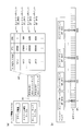
- FIG. 14 is a diagram showing how entry maps corresponding to the left view and the right view are set.
- the source packet number in the STC sequence is described in the source packet number of each entry map in the entry map
- the PTS in the STC sequence is described in the PTS of each entry map in the entry map. That is done. It shows how the correspondence between the time axis source packet and the time axis is taken by the entry map.
- the fifth row is the left-view and right-view extents recorded in an interleaved manner, and is the same as shown in the previous figures.
- the extents of the left view and the right view that should be played back at the same playback time point on the time axis are recorded at different positions in the AV data recording area, but the entry maps associated with each are used.
- the source packet at the head of the left view extent and the right view extent is uniquely accessed using the PTS.
- FIG. 15 is a diagram showing the data structure of the playlist information.
- the playlist information includes main path information, a sub path information table, and extension data as indicated by a lead line mp1.
- a lead line mp1 shows a close-up of the internal configuration of the main path information.
- MainPath is defined from a plurality of PlayItem information # 1... #M as indicated by an arrow mp1.
- PlayItem information defines one logical playback section that constitutes the MainPath.
- the structure of the PlayItem information is closed up by a lead line mp2.
- the PlayItem information includes “Clip_Information_file_name” indicating the file name of the playback section information of the AV clip to which the IN point and Out point of the playback section belong, “Clip_codec_identifier” indicating the encoding method of the AV clip, “Is_multi_angle” indicating whether or not the PlayItem constitutes a multi-angle, “connection_condition” indicating the connection state between this PlayItem (current PlayItem) and the previous PlayItem (previousPlayItem), and this PlayItem “Ref_to_STC_id [0]” uniquely indicating the STC_Sequence that is present, time information “In_time” indicating the start point of the playback section, time information “Out_time” indicating the end point of the playback section, and the user operation to be masked in this PlayItem “UO_mask_table” indicating whether or not “PlayItem_random_” indicating whether or not random access to the middle
- the playback path is composed of a set of time information “In_time” indicating the start point of the playback section and time information “Out_time” indicating the end point of the playback section. It consists of a set of “Out_time”.
- STN_table (STream Number_table) is a table that assigns a logical stream number to a combination of a stream entry including a packet ID and a stream attribute.
- the order of combinations of stream entries and stream attributes in the STN_table indicates the priority order of the corresponding streams.
- BaseView_indicator If BaseView_indicator is 0, BaseView is Left, and if it is 1, BaseView is Right.
- FIG. 16 shows the internal structure of the subpath information table.
- a lead line su1 shows a close-up of the internal configuration of the subpath information.
- the subpath information table includes a plurality of subpath information 1, 2, 3,. These subpath information is a plurality of instances derived from one class structure, and the internal configuration is common.
- a lead line su2 shows a close-up of a common internal configuration of Subpath information.
- each Subpath information includes SubPath_type indicating the type of subpath, and one or more SubPlayItem information (... SubPlayItem information # 1 to #m).
- a lead line su3 shows a close-up of the internal structure of SubPlayItem.
- the SubPlayItem information includes “Clip_information_file_name”, “Clip_codec_identifier”, “ref_to_STC_id [0]”, “SubPlayItem_In_time”, “SubPlayItem_Out_time”, “sync_PlayItem_id”, and “sync_start_PTS_of_PlayItem”.
- the internal configuration of SubPlayItem will be described.
- “Clip_information_file_name” is information for uniquely specifying a SubClip corresponding to a SubPlayItem by describing the file name of the clip information.
- “Clip_codec_identifier” indicates the encoding method of the AV clip.
- SubPlayItem_In_time is information indicating the start point of SubPlayItem on the playback time axis of SubClip.
- SubPlayItem_Out_time is information indicating the end point of SubPlayItem on the playback time axis of SubClip.
- Sync_PlayItem_id is information that uniquely designates the PlayItems constituting the MainPath that should be synchronized with the SubPlayItem.
- SubPlayItem_In_time exists on the playback time axis of Play Item specified by this sync_PlayItem_id.
- Sync_start_PTS_of_PlayItem indicates where the start point of the SubPlayItem specified by SubPlayItem_In_time exists on the playback time axis of the Play Item specified by sync_PlayItem_id with a time accuracy of 45 KHz.
- FIG. 17 shows what playback sections are defined for the left view and the right view. This figure is drawn based on FIG. 14, and In_Time and Out_Time of PlayItem are drawn on the time axis of the second stage of this figure. In_Time and Out_Time of SubPlayItem are drawn on the time axis of the first row.
- the third to fifth stages are the same as the third to fifth stages in FIG.
- the left view and right view I pictures are at the same point in time.
- Left view and right view are associated with each other by play item information and SubPlayItem information.
- FIG. 18 is a diagram showing an internal configuration of extension data in playlist information.
- a lead line et1 shows a close-up of the internal structure of the extension data.
- the extension data is composed of STN_table_extention corresponding to each of the play item information # 1 to #N.
- a lead line et2 shows a close-up of the internal configuration of STN_table_extention corresponding to PlayItem information # 1.
- STN_table_extention corresponding to PlayItem information # 1 includes a “video stream number table”.
- FIG. 19 shows the internal structure of the video stream number table.
- Stream_entry includes “ref_to_stream_PID_of_main_Clip”, “video_format”, and “frame_rate” indicating reference values for the PIDs of the PES packets constituting the primary video stream.
- the order of stream_entry in these tables means the priority of stream selection when the playback apparatus selects a stream. That is, the playback apparatus preferentially selects the entry having the highest order in the table.
- the packet ID of 0x1011 and the packet ID of 0x1012 are described in ref_to_stream_of_MainCLip.
- Content in the present specification includes playlist information managed by a certain title number, a video stream multiplexed on an AV clip referenced from the playlist information, a BD-J object described later, and a BD- A unit including an application permitted to be activated indicated by a J object, and called a “title”.
- JAR directory stores a JAR archive file (XXXXX.JAR).
- the JAR archive file is a file conforming to the specifications described in http: // java (TM) .sun.com / j2se / 1.4.2 / docs / guide / jar / jar.html.
- a JAR archive file stores multiple files in a directory structure.
- FIG. 20 shows the internal structure of a JAR archive file.
- This XXXXX.class stores bytecodes obtained by compiling a class structure described in an object-oriented language such as Java language. Such a class file defines a BD-J application and can be executed on a Java TM virtual machine.
- MANIFEST.MF corresponds to the digital certificate
- SIG-BD.SF is a file in which the hash value of MANIFEST.MF is described.
- SIG-BD.RSA is a file in which a digital certificate chain and signature information are described.
- bd.XXXXX.perm is a permission request file, and stores information on permission indicating what kind of file is allowed to be accessed by the BD-J application to be executed.
- BD-J application defined by class file in JAR archive file is Java (TM) Xlet controlled by application manager through Xlet interface.
- the Xlet interface has four states: "loaded”, “paused”, “active”, and "destoryed”.
- the Java (TM) application implements the HAVi framework specified in GEM1.0.2 using standard Java libraries for displaying JFIF (JPEG), PNG, and other graphics data.
- the HAVi framework is a GUI framework that includes the remote control navigation mechanism in GEM 1.0.2, and the Java (TM) application displays buttons, text display, online display (BBS contents) based on the HAVi framework.
- a screen display combined with a moving image display can be realized, and an operation for the screen display can be performed using a remote control.
- the PNG file in the figure stores animation data used by the BD-J application for GUI, for example.
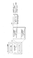
- FIG. 21 shows the internal structure of the BD-J object.
- the BD-J object is composed of an “application management table”, a “GUI management table”, and a “playlist management table”.
- the “application management table” is a table for causing the playback device to perform application signaling with the title as the life cycle.
- a lead line bj1 shows a close-up of the internal configuration of the application management table.
- the application management table includes an “application identifier” that identifies an application to be operated when a title corresponding to the BD-J object becomes the current title, and a “control code”.
- the control code indicates that this application is loaded into the heap memory and then automatically started.
- this application is loaded into the heap memory and then another application Wait for a call from, indicating that it should be activated.
- the “GUI management table” is a management table used when a running application performs GUI. Configuration information, font data used for GUI display, menu calls to GUI, and title calls are displayed by the user. If made, it contains a mask flag that specifies whether to mask these calls.
- the playback device when the application to be activated by the application management table in the BD-J object draws graphics, the playback device includes a graphics plane having a scale corresponding to the resolution of the video stream to be played back. Information for instructing the reproducing apparatus to be secured on the memory device.
- the lead line bj2 shows a close-up of the internal structure of the playlist management table.
- the playlist management table includes designation of a playlist to be automatically played when the title corresponding to the BD-J object becomes the current title.
- the playlist management table includes designation of a playlist that can be selected by an application that can be operated when the title corresponding to the BD-J object becomes the current title.
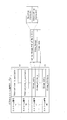
- FIG. 22A shows the internal structure of the GUI management table.
- the lead line gh1 closes up the configuration of the GUI management table.
- the GUI management table is composed of “basic plane configuration”, “display method flag”, and “extended plane configuration”.
- the “basic plane configuration” indicates a graphics plane configuration to be reserved for graphics to be combined with the base view stream (base view graphics).
- the “extended plane configuration” indicates a graphics plane configuration to be reserved for graphics to be combined with the enhanced view stream (enhanced view graphics).
- these basic plane configuration and extended plane configuration are collectively referred to as “configuration information”.
- Lead lines gh2 and gh3 indicate the setting contents of the basic plane configuration and the extended plane configuration. As shown in this leader line, the resolution code is set for the basic plane configuration and the extended plane configuration.
- FIG. 22 (b) is a diagram showing the bit assignment of the display method flag.
- it is “0”, since the GUI is viewed in plan, it indicates that there is a single graphics plane memory (called a graphics plane or image plane) to be secured.
- a graphics plane or image plane When “1”, since the stereoscopic view of the GUI is executed, it indicates that there are a plurality of graphics planes to be secured.
- FIG. 22 (c) shows the meaning content of the resolution code.
- the resolution code When the resolution code is set to “1”, it indicates that the scale of the graphics plane to be secured is 720 ⁇ 480 pixels.
- the resolution code When the resolution code is set to “2”, it indicates that the scale of the graphics plane to be secured is 960 ⁇ 540 pixels.
- the resolution code When the resolution code is set to “3”, it indicates that the scale of the graphics plane to be secured is 1920 ⁇ 1080 pixels.
- the resolution code is set to “4”, it indicates that the scale of the graphics plane to be secured is 1280 ⁇ 720 pixels.
- FIG. 23 shows the correspondence between the resolution of the video plane and the graphics plane.
- the left side shows the resolution of the video plane, and the right side shows the resolution of the graphics plane.
- the middle arrow indicates a combination of acceptable video plane resolution and graphics plane resolution. If the resolution code of the video plane is 720 ⁇ 480 pixels, as shown by the arrow kw1, setting of a resolution code of 720 ⁇ 480 pixels is permitted as the resolution code of the graphics plane.
- a resolution code of 960 ⁇ 540 pixels or a resolution code of 1920 ⁇ 1080 pixels is set as the resolution code of the graphics plane. Permissible. *
- the video plane resolution code means 1280 ⁇ 720 pixels as shown by the arrow kw4, setting of a resolution code of 1280 ⁇ 720 pixels is permitted as the resolution code of the graphics plane.
- FIG. 24A shows the setting of the GUI management table and the contents of the memory.
- a plane memory corresponding to the resolution code in the basic plane configuration is secured in the memory.
- a plane memory having a scale of WidthB ⁇ HeightB is secured in the memory.
- the extended graphics plane is not secured.
- FIG. 24B shows the setting of the GUI management table and the contents of the memory.
- the plane memory corresponding to the resolution code in the basic plane configuration and the plane memory corresponding to the resolution code in the extended plane configuration are stored in the memory. Secured.
- a plane memory having a scale of WidthB ⁇ HeightB is secured in the memory.
- the display method flag is “1”
- an extended graphics plane is secured.
- a plane memory of WidthE ⁇ HeightE is secured in the memory.
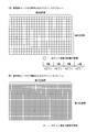
- FIG. 25A shows a graphics plane secured with a resolution code “2”.
- a graphics plane secured with a resolution code of “2” consists of a 32-bit area of 960 ⁇ 540. That is, the graphics plane decoded with the resolution code “2” is a memory allocation that can store RGB values of 32 bits per pixel at a resolution of 960 ⁇ 540.
- the 32-bit RGB value includes 8-bit red pixel luminance (R value), 8-bit green pixel luminance (G value), 8-bit blue pixel luminance (B value), and transparency alpha value. .
- FIG. 25B shows a graphics plane secured with a resolution code “3”.
- the graphics plane secured when the resolution code is “3” is composed of a 32-bit bit area of horizontal 1920 ⁇ vertical 1080. This is an area having a memory allocation that can store RGB values of 32 bits per pixel with a resolution of 1920 ⁇ 1080.
- the application determines the graphics writing position based on the resolution code coordinate system specified by the configuration information in the GUI management table. Specifically, graphics writing coordinates are defined in a coordinate system with the upper left pixel as the origin among pixels of resolution codes such as 1920 ⁇ 1080 and 720 ⁇ 480.
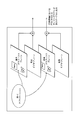
- FIG. 26 shows temporal transition of securing and releasing of the graphics plane.
- the first level shows the video content
- the second level shows the time axis.
- the third level shows the internal structure of the BD-J object
- the fourth level shows the contents of the memory device.
- titles # 1 and # 3 are planar content
- title # 2 is stereoscopic content
- the GUI management table in the BD-J object corresponding to titles # 1 and # 3 Assume that the display method flag is set to "0". It is also assumed that the display method flag is set to “1” in the GUI management table of the BD-J object corresponding to title # 2.
- the temporal transition of securing the graphics plane of the memory device under the above conditions is as shown in the fourth row.
- the graphics plane in the memory device is cleared at the timing when the current title becomes title # 1, and then the basic graphics plane is secured in the memory device.
- the graphics plane in the memory device is cleared, and thereafter, the basic graphics plane and the extended graphics plane are secured in the memory device.
- the extended graphics plane is secured in the memory device only during the period when the current title becomes title # 2, and when the current title becomes title # 3, the extended graphics plane is released, so the capacity of the memory device becomes longer due to the graphics plane. It will not be occupied.
- GUI processing typical graphics rendered by a BD-J application are menus and animations.
- the menu includes a plurality of button members, and each button member has a state such as a normal state, a focus state, and an active state.
- the button that should be in focus can be switched, and the BD-J application performs processing corresponding to the currently focused button in response to the press of the Enter key on the remote control.
- Animation is performed by sequentially overwriting graphics already written in graphics at certain time intervals.
- the graphics writing for realizing the animation will be described.
- the graphics constituting the animation are managed by numerical values for graphics management, and the graphics data image corresponding to the numerical values is displayed on the screen for a certain period of time.
- new graphics are generated on the application side for a certain period of time.
- the stored contents of the graphics plane are overwritten using newly generated graphics data.
- the numerical value for graphics management is updated.
- the number of repetitions of the above-described series of operations in a unit time for example, one second
- application execution speed the number of timings at which the contents stored in the graphics plane are updated per unit time. It can be increased or decreased. As a result, it becomes possible to increase or decrease the responsiveness of the GUI display by the graphics drawing by the application with respect to the input.
- the graphics writing position in the coordinate system is shifted in order to realize stereoscopic viewing of graphics. In this way, graphics stereoscopic viewing is realized.
- FIG. 27 shows the writing of graphics by the BD-J application.
- the display method flag is “1”
- an extended graphics plane is added.
- the BD-J application writes graphics to each of the basic graphics plane and the extended graphics plane.
- FIG. 28 shows an example of a stereoscopic video that is played back when the playback of the base view stream and the enhanced view stream and the GUI processing by the BD-J application are linked. Since graphics are written in each of the basic graphics plane and the extended graphics plane, menus and animations appear three-dimensionally in the stereoscopic video.
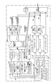
- FIG. 29 shows the internal structure of the playback device.
- main components constituting the playback apparatus are a front end unit 105, a system LSI 106, a memory device 107, and a back end unit 108.
- the front end unit 105 is a data input source.
- the front end unit 105 includes, for example, a BD-ROM drive 109 and a local storage 110.
- the system LSI 106 is composed of logic elements and forms the core of the playback device.
- the system LSI 106 includes, for example, an MPU 21, a plane controller 17, a demultiplexer 6, a video decoder 7a, a video decoder 7b, an audio decoder 9, a color conversion unit 18a, a color conversion unit 18b, a combiner 19a, and a combiner 19b.
- the system LSI may be composed of one chip or a plurality of chips.
- the memory device 107 is composed of an array of memory elements such as SDRAM.
- the memory device 107 includes, for example, a read buffer 1, a read buffer 2, a heap memory 31, a dynamic scenario memory 30, a static scenario memory 13, a byte code interpreter, a command interpreter, an embedded ROM 22, and a playback control engine 14.
- PSR set 12 basic graphics plane 15, extended graphics plane 16, basic video plane 8a, and extended video plane 8b.
- the area on the memory device is recognized as a unified memory space. Therefore, when the BD-J application operates, the area of the memory device is used as a resource. Provided for use by BD-J applications. A plurality of plane memories are mapped to a part of the memory space in the CPU.
- the back end unit 108 is a connection interface between the playback device and other devices.
- the back end unit 108 includes, for example, the HDMI transmitting / receiving unit 10. *
- the front end unit 105 includes the BD-ROM drive 109 and the local storage 110, for example.
- the BD-ROM drive 109 performs loading / ejecting of the BD-ROM, and reads out the extent constituting the base view stream and the extent constituting the enhanced view stream from the BD-ROM in accordance with an instruction from the system LSI 106.
- the BD-ROM drive 109 includes, for example, a semiconductor laser (not shown), a collimating lens (not shown), a beam splitter (not shown), an objective lens (not shown), a condensing lens (not shown), light
- An optical head (not shown) having a detector (not shown) is provided.
- the light beam emitted from the semiconductor laser passes through the collimator lens, the beam splitter, and the objective lens, and is condensed on the information surface of the optical disk.
- the condensed light beam is reflected / diffracted on the optical disk, and is collected on the photodetector through the objective lens, the beam splitter, and the condenser lens.
- the generated signal corresponds to the data read from the BD-ROM according to the amount of light collected by the photodetector.
- the local storage 110 includes built-in media and removable media, and is used for storing downloaded additional content and data used by applications.
- the storage area for additional content is divided for each BD-ROM, and the area that an application can use to hold data is divided for each application.
- merge management information that describes how merged downloaded content and data on the BD-ROM are merged is also stored in the built-in and removable media.
- Build-in media is a writable recording medium such as a hard disk drive or memory built in the playback device.
- the removable media is, for example, a portable recording medium, and preferably a portable semiconductor memory card such as an SD card.
- a playback device has a slot (not shown) for mounting a removable medium and an interface (for example, a memory card) for reading the removable medium mounted in the slot.
- an interface for example, a memory card
- the removable media and the playback device are electrically connected and recorded on the semiconductor memory using an interface (for example, a memory card I / F). It is possible to read out the converted data into an electrical signal.
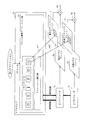
- FIG. 30 is a diagram showing the components in the front end unit 105 to the back end unit 108.
- a demultiplexer 6 video decoders 7a and b, basic video planes 8a and b, an audio decoder 9, and an HDMI interface 10.
- Playback state / setting register set 12 static scenario memory 13
- playback control engine 14 basic graphics plane 15, extended graphics plane 16, plane controller 17, color converters 18a, b, synthesizers 19a, b, MPU 21, ROM 22
- components such as a dynamic scenario memory 30 and a heap memory 31.
- the read buffer 1 is a buffer for temporarily storing source packets constituting extents constituting a base view stream read from the BD-ROM drive 1 and adjusting the transfer speed and transferring the packets to the demultiplexer 6. And has the scale of “RB1” as described above.
- the read buffer 2 is a buffer for temporarily storing source packets constituting extents constituting the enhanced view stream read from the BD-ROM drive 1, adjusting the transfer speed, and transferring the packets to the demultiplexer 6. And has the scale of “RB2” as described above.
- the demultiplexer 6 includes a source packet depacketizer and a PID filter. If the extents constituting the base view stream and the enhanced view stream are transferred via the read buffers 1 and 2, the base view video is transmitted. The TS packets constituting the stream and the TS packets constituting the enhanced view video stream are separated from the extent and transferred to the video decoder 7a and the video decoder 7b.
- the video decoder 7a decodes the TS packets constituting the base view stream output from the demultiplexer 6 and writes the uncompressed picture into the basic video plane 8a.
- the video decoder 7b decodes the enhanced view stream output from the demultiplexer 6, decodes the TS packet, and writes a non-compressed picture in the extended video plane 8b.
- the basic video plane 8a is a memory for storing uncompressed pictures that make up the base view stream.
- the extended video plane 8b is a memory for storing uncompressed pictures that make up the enhanced view stream.
- the audio decoder 9 decodes the audio frame output from the demultiplexer 6 and outputs uncompressed audio data.
- the HDMI transmission / reception unit 10 includes, for example, an interface compliant with the HDMI standard (HDMI: High Definition Multimedia Interface), and performs transmission / reception so as to comply with the HDMI standard with a device (in this example, the television 103) connected to the playback device.
- the picture data stored in the basic video plane 8 a and the extended video plane 8 b and the uncompressed audio data decoded by the audio decoder 13 are transmitted to the television 103 via the HDMI interface 10.
- the television 103 holds information regarding whether it is compatible with stereoscopic display, information regarding resolution capable of planar display, and information regarding resolution capable of stereoscopic display, and when there is a request from the playback device via the HDMI interface, The television 103 returns the requested required information (for example, information regarding whether or not stereoscopic display is supported, information regarding resolution capable of planar display, and information regarding resolution capable of stereoscopic display) to the playback device.
- information regarding whether or not the television 103 supports stereoscopic display can be acquired from the television 103 via the HDMI transmission / reception unit 10.
- the playback status / setting register (Player Status / Setting Register) set 12 is an area where the playback status of the playlist and arbitrary information used by the content can be stored.
- the playback status of the playlist indicates the status of which AV data is used in the various AV data information described in the playlist and which position (time) of the playlist is being played. Is.
- the playback control engine 14 stores the contents in the PSR set 12.
- the value specified by the application can be stored or the stored value can be stored in the application according to the instruction from the command interpreter that is the HDMV mode operation subject or the Java platform that is the BD-J mode operation subject. It is possible to pass Hereinafter, typical ones of PSR will be described.
- PSR4 is set to a value between 1 and 100 to indicate the current title number.
- ⁇ PSR5 indicates the current chapter number when set to a value between 1 and 999, and indicates that the chapter number is invalid in the playback device when set to 0xFFFF.
- PSR6 is set to a value between 0 and 999 to indicate the current playlist number.
- ⁇ PSR7 is set to a value between 0 and 255 to indicate the current play item number.
- the static scenario memory 13 is a memory for storing current playlist information and current clip information.
- Current playlist information refers to information that is currently processed among multiple playlist information that can be accessed from a BD-ROM, a built-in media drive, or a removable media drive.
- Current clip information refers to information that is currently processed among a plurality of clip information that can be accessed from a BD-ROM, a built-in media drive, or a removable media drive.
- the playback control engine 14 executes an AV playback function and a playlist playback function in response to a function call from a command interpreter that is an HDMV mode operating entity and a Java platform that is an BD-J mode operating entity.
- the AV playback function is a group of functions followed from DVD players and CD players. Playback start, playback stop, pause, release of pause, release of still image function, fast forward with specified playback speed, playback speed Is a process such as rewind, audio switching, sub-video switching, angle switching, etc., designated as immediate values.
- the playlist playback function refers to performing playback start and playback stop in accordance with current playlist information and current clip information constituting the current playlist in the AV playback function.
- the basic graphics plane 15 is a plane memory secured according to the basic plane configuration information in the BD-J object.
- the extended graphics plane 16 is a plane memory secured according to the extended plane configuration information in the BD-J object when the display method flag is set to “1”, that is, stereoscopic display (set to ON).
- the plane controller 17 outputs an image obtained by combining the graphics data in the basic graphics plane and the picture data in the basic video plane to perform planar display, or in the basic graphics plane
- the graphics data of the video and the picture data in the basic video plane are output as a left-view moving image
- the graphics data in the extended graphics plane and the picture data in the extended video plane are output as a right-view moving image.
- it is controlled whether or not the stereoscopic display is performed.
- stereoscopic display an image obtained by combining the basic graphics plane and the basic video plane and an image obtained by combining the extended graphics plane and the extended video plane are switched and displayed in a short time interval.
- the color conversion unit 18a converts the pixel code stored in the basic graphics plane 15 into pixel values such as Y, Cr, and Cb using a color lookup table.
- the color conversion unit 18b converts the pixel code stored in the extended graphics plane 16 into pixel values such as Y, Cr, and Cb using a color lookup table.
- the synthesizer 19a synthesizes each pixel of uncompressed picture data stored in the basic video plane 8a and each pixel of graphics developed on the basic graphics plane 15.
- the synthesizer 19b synthesizes each pixel of uncompressed picture data stored in the extended video plane 8b and each pixel of graphics developed on the extended graphics plane 16.
- the MPU 21 is the core of the computer architecture of the playback device, fetches and decodes the native code stored in the ROM 22, and executes the processing of the playback device based on the native code.
- the ROM 22 stores a built-in program in the playback device in advance.
- the dynamic scenario memory 30 is a memory that stores a current dynamic scenario and is used for processing by a command interpreter that is an operation subject in the HDMV mode and a Java platform that is an operation subject in the BD-J mode.
- the current dynamic scenario refers to an index.bdmv, BD-J object, or movie object that is currently being executed among BD-ROM, built-in media, and removable media.
- the heap memory 31 is a stack area where system application byte codes, BD-J application byte codes, system parameters used by system applications, and application parameters used by BD-J applications are arranged.
- FIG. 31 is a diagram showing a software layer model in the playback device.
- this software layer model there are three operating entities on the MPU 21: an HDMV module, a BD-J module, and a mode management module. These are controlled by Index.bdmv, BD-J object, and movie object existing in the dynamic scenario memory 30.
- HDMV module the HDMV module
- BD-J module the HDMV module
- mode management module the HDMV module
- the command interpreter 40 which is an example of an HDMV module, is a DVD virtual player that is an HDMV mode operation subject, and an HDMV mode execution subject.
- the command interpreter which is the main operation in the HDMV mode, decodes and executes the navigation commands that make up the scenario program. Since navigation commands are described in a syntax similar to DVD-Video, DVD-Video-like playback control can be realized by executing such navigation commands.
- the BD-J platform 41 is a Java platform that is the main subject of operation in the BD-J mode, and is full of Java2Micro_Edition (J2ME) Personal Basis Profile (PBP 1.0) and Globally Executable MHP specification (GEM1.0.2) for package media targets. Implemented.
- J2ME Java2Micro_Edition
- PBP 1.0 Personal Basis Profile
- GEM1.0.2 Globally Executable MHP specification
- the module manager 42 which is an example of a mode management module, holds Index.bdmv read from the BD-ROM, built-in media drive, or removable media drive, and performs mode management and branch control.
- the mode management by the module manager 42 is module assignment of which command interpreter 40 and BD-J module execute a dynamic scenario.
- the BD-J module includes middleware 35, a bytecode interpreter 32, and a system application existing on the heap memory 31.
- system applications on the heap memory 31 among the class libraries included in the class loader 33, the application manager 34, and the middleware 35, there are those that are arranged on the heap memory 31 and executed.
- these components will be described.
- the byte code interpreter 32 converts the byte code constituting the BD-J application stored in the heap memory 31 and the byte code constituting the system application into a native code, and causes the MPU 21 to execute it.
- the class loader 33 is one of the system applications, and loads the BD-J application by reading the byte code from the class file existing in the JAR archive file and storing it in the heap memory 31.
- the application manager 34 is one of the system applications, and based on the application management table in the BD-J object, the application manager 34 starts the BD-J application or terminates the BD-J application. Perform signaling.
- the middleware 35 is an operating system for embedded software, and includes a kernel and device drivers.
- the kernel provides a playback device-specific function to the BD-J application in response to an application programming interface (API) call from the BD-J application.
- API application programming interface
- hardware control such as activation of an interrupt handler unit by an interrupt signal is realized.
- Each area of the memory device is managed by the middleware 35 using, for example, a memory pool management function and a heap area management function.
- the memory pool management function manages an empty memory area, gives a requested memory size to an application as necessary, and returns to a state accumulated in the memory when use is completed.
- heap area management a memory pool is set in a free memory area, and a memory of a necessary size is provided in response to a task request.
- the BD-J platform 41 instructs the plane controller 17 to draw based on the configuration information described in the GUI management table associated with the current title.
- the basic graphics plane is instructed to draw the left-view graphics and the extended graphics plane to the right-view graphics.
- the graphics drawing for the left view is an image obtained by rendering the viewpoint position at the position of the viewer's left view
- the graphics drawing for the right view is rendered by the position of the viewpoint at the position of the viewer's right view. It is an image.
- FIG. 32 is a diagram in which Index.bdmv and BD-J objects are drawn on the left side and a software layer model is drawn on the right side. Arrows indicate how the components of Index.bdmv and BD-J objects are delivered.
- An arrow with a circle symbol “1” schematically indicates reading of a title number and an operation mode object ID by the module manager 42.
- An arrow with a circle symbol “2” schematically indicates reading of the application management table by the application manager.
- An arrow with a circle symbol “3” schematically indicates reading of the playlist management table by the reproduction control engine 14, and an arrow with a circle symbol “4” schematically indicates reading of the GUI management table by the plane controller 17. Yes.
- the plane controller 17 instructs the synthesizer 19a to synthesize and output the basic graphics plane 15 and the basic video plane 8a in the case of plane display, and synthesizes and outputs to the basic graphics plane 15 and the basic video plane 8a in the case of stereoscopic display. To the synthesizer 19a, and the synthesized output of the extended graphics plane 16 and the extended video plane 8b to the synthesizer 19b.
- FIG. 33 is a diagram in which the BD-J application existing on the software layer model, the video plane, and the graphics plane are drawn together.
- a plurality of graphics constituting the animation are developed.
- the arrow schematically shows writing by the BD-J application. That is, it can be seen that the BD-J application writes the graphics corresponding to one frame in the animation to the basic graphics plane and the extended graphics plane one by one as the video stream is played back.
- FIG. 34 is a flowchart showing a processing procedure by the module manager 42.
- the processing procedure in this figure has a main loop composed of step S1-step S2-step S3-step S4.
- Step S1 is a determination as to whether or not a current title has been newly selected in response to a user operation. If so, in step S7, all the graphics planes in the memory device are released and the process proceeds to step S8.
- Step S8 is a determination of whether or not a playlist management table exists in the BD-J object corresponding to the current title. If it does not exist, playback of the play list described in the play list management table for the previous title is stopped (step S9).
- step S10 the reproduction of the AutoPlay playlist is started (step S10).
- step S11 it is determined whether or not the GUI management table exists in the BD-J object corresponding to the current title.
- Step S12 is a determination step executed when the GUI management table exists.
- the configuration information in the GUI management table is set in the plane controller 17 and initialization is executed (step S12).
- Step S15 is a determination as to whether or not the application management table exists in the BD-J object corresponding to the current title. If it exists, the previous title is not set as the live range, but the current title is set as the live range.
- a Java (registered trademark) application having the AutoRun attribute is started (step S16). If it does not exist, the application that has the previous title as the life span but does not have the current title as the life span is stopped (step S17).
- Step S18 it is determined whether or not the Java (registered trademark) application has been successfully activated. If the activation is successful (Yes in step S18), the playback image of the AutoPlay playlist is quota (1/4). (Step S19) is realized.
- step S18 the loop process consisting of steps S23, S24, S16 and S18 is executed.
- the control variable in this loop process is a restart counter.
- the restart counter is a counter that defines the number of restarts of the application.
- the restart counter is reset when the flowchart is started, and it is determined whether or not it is 0 in step S23. If not 0, the restart counter is decremented in step S24.
- the AutoRun application is repeatedly started unless the restart counter is 0. Such repetition ensures the activation of the application.
- Step S2 is a determination of whether or not the main application is not being executed. If so, the determination of step S5 is performed. Step S5 is a determination as to whether the application has ended normally. If the process has ended abnormally, the processes of steps S21 and S22 are executed. If the process is normally completed, steps S21 to S22 are not executed, and the process returns to the main loop including steps S1 to S4.
- Step S21 is a determination as to whether or not the AutoPlay playlist is being played back. If playback is in progress, the playback control engine is instructed to make the playback image of the AutoPlay playlist full screen (Step S22). Thereafter, the process proceeds to step S23. As a result of the transition to step S23, the loop process including steps S14 to S17 is executed even at the abnormal end. As a result, the restart of the application is repeated until the number of restart counters becomes zero.
- Step S4 is a determination as to whether or not a BD-ROM is present in the BD drive 1. If there is no BD-ROM, a termination instruction is issued to all applications (step S6).
- FIG. 35 is a flowchart showing the playback procedure of playlist information.
- step S31 the current PlayItem number is initialized to “1”, and the process proceeds to a loop of steps S32 to S42.
- This loop repeats the process of executing steps S32 to S40 for the current play item number and incrementing the current play item number (step S41) until the current play item number is final. Yes (Yes in step S42).
- Steps S32 to S40 are as follows.
- step S32 the current PlayItem.In_Time and the current PlayItem.Out_Time are converted into Start_SPN [i] and End_SPN [i] using the entry map corresponding to the packet ID of the base view.
- the base view stream is selected (step S33), the current stream number of the selected stream is written to the PSR (step S34), and the SubPlayItem corresponding to the current stream number is specified (step S35).
- SubPlayItemIn_Time and SubPlayItemOut_Time specified using the entry map [j] corresponding to the enhanced view packet ID [j] are converted to Start_SPN [j] and End_SPN [j] (step S36).
- step S37 The extent belonging to the read range [i] for reading the TS packet [i] with the packet ID [i] from Start_SPN [i] to the extension data [i] is specified (step S37), and the TS packet with the packet ID [j] An extent belonging to the read range for reading [j] from Start_SPN [j] to End_SPN [j] is specified (step S38).
- step S39 the extents belonging to the reading ranges [i] and [j] are sorted in ascending order of the addresses, and the extents belonging to the reading ranges [i] and [j] are continuously used by using the addresses sorted in step S40. Instruct the drive to read automatically.
- FIG. 36 is a flowchart showing the processing procedure of the plane controller.
- step S51 a plane memory having the number of vertical pixels ⁇ the number of horizontal pixels ⁇ the number of bytes per pixel in the basic plane configuration information in the GUI management table of the BD-J object is secured on the RAM, and the process proceeds to steps S52 and S53.
- Step S52 is a step of determining whether or not the television 103, which is the counterpart device connected to the playback device via HDMI, has a stereoscopic processing capability.
- Step S53 is a display method flag for the BD-J object. Is a step of determining whether or not is “1”. If either determination is No, plane control for planar view is executed.
- step S54 If any step is Yes, it is determined that stereoscopic display is possible, and in step S54, the number of vertical pixels ⁇ the number of horizontal pixels ⁇ one pixel in the extended plane configuration information in the GUI management table of the BD-J object.
- the plane memory having the number of bytes is secured on the RAM, and the process proceeds to step S55.
- Step S55 is for monitoring whether or not a display period of 1/48 seconds has arrived. If it has arrived, step S55 becomes Yes and the processing of steps S56 to S60 is executed. Specifically, a video plane and a graphics plane to be displayed are determined (step S56), and pixel data for one line stored in the graphics plane is read and converted into Y, Cr, and CB (step S56). S59) The process of synthesizing Y, Cr, CB for one line read out from the video plane for each pixel (step S60) is repeated for all lines in the graphics plane and the video plane (step S57, step S58). ).
- step 52 inquires whether or not the television 103 that is the counterpart device connected to the playback apparatus has stereoscopic processing capability, but the playback apparatus 102 has a user interface. Alternatively, the user may set whether to perform stereoscopic output in advance.
- FIG. 37 is a flowchart showing a processing procedure of GUI processing by the BD-J application.
- a graphics scaling factor is determined from the resolution in the configuration information and the resolution of the graphics constituting the animation data
- the base view graphics display timing is awaited. If it arrives, in step S73, the coordinates ((X, Y)) for displaying the base view graphics are calculated with the scaling factor determined (step S73), and the coordinates (XB, YB) of the basic graphics plane are calculated.
- Base view graphics are written (step S74).
- Step S75 is a determination of whether or not the display method flag is on. If the display method flag is “0” (that is, off), the process returns to step S72.
- step S76 it waits for the display timing of enhanced view graphics. If it arrives, the coordinate ((X, Y)) for displaying the enhanced view graphics is calculated with the scaling factor determined in step S77 (step S77), and the coordinate (XE, YE) of the extended graphics plane is calculated. Enhanced view graphics is written (step S78). Thereafter, the process returns to step S72.
- the configuration information display method flag in the GUI management table includes a plurality of plane memories (a plurality of graphics planes and a plurality of video planes) in order to realize graphics stereoscopic viewing. Since it indicates whether or not it is necessary to reserve, when reproducing the content that does not require addition of plane memory, the scale of the plane memory corresponding to each of the graphics plane and video plane to be secured returns to one ( That is, a basic video plane and a basic graphics plane may be secured respectively).
- FIG. 38 is a diagram showing the frame accuracy animation execution unit 80.
- the frame accuracy animation execution unit 80 takes in the configuration information in the GUI management table in the BD-J object, and uses the coordinate system indicated in the configuration information as a reference for animation drawing.
- the frame-accuracy animation execution unit then designates individual graphics included in the animation data if a function call is made with the display ratio of the file path that specifies the file that stores the animation data and the display rate in the animation. Playback at the selected display rate and compositing with moving images.
- animation data is written to the basic graphics plane and the extended graphics plane while shifting the graphics writing position in consideration of parallax.
- the graphics are written while shifting the respective graphics writing coordinates in the basic graphics plane and the extended graphics plane, so that the graphics can be stereoscopically viewed.
- the processing load of the BD-J application can be reduced.
- the GUI management table in the BD-J object preferably represents the resolution code and the display method flag as an integrated resolution code. For example, when a plane memory of 1920 ⁇ 1080 scale with HD image quality is to be secured for stereoscopic playback, a resolution code of HD3D — 1920 ⁇ 1080 is described in the GUI management table.
- a resolution code of HD3D — 1280 ⁇ 1080 is described in the GUI management table.
- the playback device 102 includes a local storage including a built-in media drive and removable media and is configured to write to these, the playback device described in this specification is a recording device. It can be said that it also has a function.
- the playback device 102 functions as a recording device, the management object is written according to the following two modes.
- writing of a BD-J object as a management object is performed as follows. That is, when a BD-ROM is loaded, additional content corresponding to the BD-ROM is acquired from the WWW server via the network in accordance with a request from the application.
- the acquired additional content includes a BD-J object in which a GUI management table is described.
- a control unit that performs recording control writes the acquired BD-J object in the local storage in accordance with a request from the application. By doing so, the virtual package can be constructed by combining the content recorded on the BD-ROM and the additional content recorded on the local storage.
- the disc root certificate identifier, the identifier of the organization that distributed the BD-ROM content, and the identifier of the BD-ROM are recorded in the BD-ROM, and the area in which the additional content is to be stored is the disc root
- the file path includes a certificate identifier, an organization identifier, and a BD-ROM identifier.
- the application performs writing by passing a file path that specifies an area in which additional content is to be stored to the control unit.
- the file path used for writing to the local storage has a directory name of 8 characters or less, and , Including the designation of the file name and extension in an 8.3 file system having a file name and an extension name of 3 characters or less.
- BD-J object that is a management object is written as follows.
- the playback device 102 when the playback device 102 receives the supply of the BD-J object by the on-demand manufacture service or the electronic sell-through service, the default directory and the MODEST directory are created under the root directory in the removable medium, and the MODEST Create a BDMV directory under the directory.
- the MODEST directory is a first MODEST directory
- the first MODEST directory is a MODEST directory that is created when the service is received for the first time.
- the control unit in the playback apparatus 102 creates a MODEST directory corresponding to the second or later service.
- the control unit writes the startup program in the default directory and writes the BD-J object in the BDMV directory under the MODEST directory.
- This startup program is a program that is to be executed first when a recording medium is loaded in the playback device 102.
- the startup program displays a menu for accepting an operation for selecting a BDMV directory from the user on the playback device 102, and the root program is executed.
- the playback device 102 is caused to execute the change function.
- This route change function is a function for recognizing the MODEST directory to which the selected BDMV directory belongs as the root directory when the selection operation on the menu is performed by the user.
- the BD-J application may be, for example, an electronic commerce (EC) client application or an online online game. Further, various online services may be supplied to the user in cooperation with the search engine.
- GUI management table is provided in the BD-J object.
- the GUI management table is associated with the playlist information and the play item information, and the timing when the current playlist becomes a specific playlist or the current When a play item becomes a specific play item, the plane memory may be released and then the plane memory for stereoscopic playback or the plane memory for planar playback may be secured. . By doing so, the area management of the memory device is performed with a more precise time accuracy.
- Video stream for stereoscopic viewing Recording a video stream for left view and right view on a BD-ROM is merely an example. For each picture, a video stream representing a depth value for each pixel may be recorded on the BD-ROM as an enhanced view video stream for playback.
- the BD-J Extension includes various packages specialized to give the Java (TM) platform functionality beyond GEM [1.0.2].
- the packages supplied with BD-J Extension are as follows.
- ⁇ Org.bluray.media This package provides special features that should be added to Java (TM) Media FrameWork. Control over angle, audio, and subtitle selection is added to this package.
- TM Java
- ⁇ Org.bluray.ti This package includes API for mapping "services" to "titles” in GEM [1.0.2], a mechanism for querying title information from BD-ROM, and a mechanism for selecting new titles.
- Org.bluray.application This package includes an API for managing the lifetime of an application.
- Org.bluray.ui This package defines constants for key events specific to BD-ROM, and includes classes that realize synchronization with video playback.
- Org.bluray.vfs In order to seamlessly play back data regardless of the location of this data, this package can be used for content recorded on BD-ROM (on-disc content) and content on Local Storage that is not recorded on BD-ROM (off Provides a binding scheme for -disc content).
- the Binding Scheme associates content (AV clip, subtitle, BD-J application) on BD-ROM with related content on Local Storage. This Binding Scheme realizes seamless playback regardless of the location of the content. (Control contents of the plane controller)
- the plane controller processing requires specific control for accessing the SDRAM.
- the SDRAM reads from the memory array, the ROW address decoder that outputs the ROW address output to the address pin in time division to the memory array, the COLUMN address decoder that outputs the COLUMN address output to the address pin in time division, and the memory array. It has a page data buffer that holds the output data of one page length and outputs it to the data pin, and a word length register that indicates the word length to be burst read to the page data buffer. Since SDRAM employs a capacitor as a storage element, spontaneous discharge occurs. Therefore, in the SDRAM, it is necessary to refresh each storage element, and an additional circuit for the refresh is required.
- the plane controller When a picture is stored in the SDRAM, the plane controller forms a command with a combination of the states of RAS, CAS, WE, CS, and CKE, and executes read / write with the combination of this and the address. For example, when the burst transfer mode is used, an activation command is issued and a ROW address is issued to the SDRAM address pin. Issue a READ command after a certain delay from the issue, and issue a COLUMN address to the address pin. (Scope of programming language) In the above embodiment, Java (TM) is used as the programming language of the virtual machine, but other than Java (TM), such as B-Shell used in UNIX (TM) OS, Perl Script, ECMA Script, etc. It may be a programming language.
- BD-ROM drive has been described as an example of a BD-ROM as an example of a recording medium and an example of specific means having a function of reading data from a BD-ROM.
- BD-ROM is merely an example, and even if the recording medium is an optical disk medium such as BD-R, BD-RE, DVD, or CD, data having the above-described data structure is stored in these recording media.
- the operation described in the above embodiment is possible.
- the recording medium in each embodiment includes all package media such as an optical disk and a semiconductor memory card.
- the recording medium according to the present embodiment has been described by taking an example of an optical disc (for example, an existing readable optical disc such as a BD-ROM or DVD-ROM) on which necessary data is recorded.
- a terminal device having a function of writing 3D content including data necessary for carrying out the present invention distributed via broadcasting or a network to an optical disc (for example, the function described on the left may be incorporated in a playback device) It may be good or may be a device different from the playback device) and recorded on a writable optical disc (for example, an existing writable optical disc such as BD-RE, DVD-RAM) and the recorded optical disc
- a writable optical disc for example, an existing writable optical disc such as BD-RE, DVD-RAM
- the present invention can be implemented even if the recording medium is a removable medium (semiconductor memory card) such as an SD memory card, for example, in addition to the optical disk.
- a removable medium semiconductor memory card
- semiconductor memory card such as an SD memory card
- the data, the heap memory 31, the dynamic scenario memory 30, and the static scenario memory 13 are transferred to the read buffer 1 and the read buffer 2 via the BD-ROM drive 109 shown in FIG.
- the read buffer 1 and the read buffer 2 are connected via an interface (memory card I / F) for reading data in the semiconductor memory card.
- the data may be transferred to the heap memory 31, the dynamic scenario memory 30, and the static scenario memory 13.
- the playback device 102 and the semiconductor memory card are electrically connected via the memory card I / F.
- Data recorded on the semiconductor memory card may be configured to be transferred to the read buffer 1, the read buffer 2, the heap memory 31, the dynamic scenario memory 30, and the static scenario memory 13 via the memory card I / F.
- a part of the data may be encrypted as necessary from the viewpoint of protecting the copyright and improving the confidentiality of the data.
- the encrypted data may be data corresponding to a video stream, data corresponding to an audio stream, or data corresponding to a stream including them.
- data for example, a device key
- a key necessary for decrypting the encrypted data in the BD-ROM is stored in advance in the playback device.
- the BD-ROM decrypts the data corresponding to the key necessary for decrypting the encrypted data (for example, the MKB (media key block) corresponding to the device key described above) and the encrypted data.
- Data obtained by encrypting the key itself (for example, the above-described device key and encrypted title key corresponding to the MKB) is recorded.
- the device key, the MKB, and the encrypted title key are paired, and can also be associated with an identifier (for example, a volume ID) written in an area that cannot be normally copied (area called BCA) on the BD-ROM. Has been. If this combination is not correct, the code cannot be decrypted.
- a key necessary for decryption (for example, a title key obtained by decrypting the encrypted title key based on the above-described device key, MKB, and volume ID) can be derived.
- the encrypted data can be decrypted using the necessary key.
- the playback is performed.
- the data is not played back. This is because the key (title key) necessary for decrypting the encrypted data is recorded on the BD-ROM with the key itself encrypted (encrypted title key), and a combination of MKB and device key. If is not correct, the key necessary for decryption cannot be derived.
- the playback apparatus is configured such that the video stream is decoded by the decoder using the title key, and the audio stream is decoded by the audio decoder.
- the BD-ROM has been described as an example of the recording medium.
- the recording medium is not necessarily limited to the BD-ROM.
- a readable / writable semiconductor memory for example, an SD card or the like is portable. Even when it is applied to a semiconductor memory card, it can be implemented.
- data corresponding to data recorded on the BD-ROM may be recorded on a semiconductor memory card using, for example, electronic distribution, and reproduced from the semiconductor memory card. Even when the necessary data is distributed using electronic distribution and the distributed data is recorded, some or all of the distributed data is encrypted and distributed as necessary. However, it is desirable to record the data necessary for the semiconductor memory while being encrypted. For example, an operation for recording data (distributed data) corresponding to the data described in the present embodiment in the semiconductor memory using electronic distribution will be described.
- the above-described operation may be configured such that the playback device described in the present embodiment can perform such an operation, or distribution data is stored in a semiconductor memory separately from the playback device of the present embodiment. It is also possible to use a form that is performed by a dedicated terminal device that performs this. Here, an example performed by the playback apparatus will be described. Further, an SD card will be described as an example of a recording destination semiconductor memory.
- the playback device When recording distribution data on an SD memory card inserted in a slot provided in the playback device, first, transmission of distribution data is requested to a distribution server (not shown) that stores the distribution data. At this time, the playback device uses the identification information for uniquely identifying the inserted SD memory card (for example, an identification number unique to each SD memory card, more specifically, for example, the serial number of the SD memory card) to the SD memory card. And the read identification information is transmitted to the distribution server together with the distribution request.
- a distribution server not shown
- the identification information for uniquely identifying the SD memory card corresponds to, for example, the volume ID described above.
- the distribution server encrypts necessary data (for example, a video stream, an audio stream, etc.) among the data to be distributed using a key (for example, a title key) necessary for decryption. Stored on the server.
- necessary data for example, a video stream, an audio stream, etc.
- a key for example, a title key
- the distribution server holds a secret key and is configured so that different public key information can be dynamically generated for each unique identification number of the semiconductor memory card.
- the distribution server is configured to be able to encrypt the key (title key) necessary for decrypting the encrypted data (that is, configured to generate an encrypted title key).
- the generated public key information includes, for example, information corresponding to the above-described MKB, volume ID, and encrypted title key.
- the encrypted data is, for example, a key necessary for decryption (for example, Based on the device key, MKB, and identification number unique to the semiconductor memory, a title key obtained by decrypting the encrypted title key) is obtained, and using the obtained key (title key) necessary for decryption, Encrypted data can be decrypted.
- the playback device records the received public key information and distribution data in the recording area of the semiconductor memory card inserted in the slot.
- the received public key information includes, for example, a public key body (for example, the above-described MKB and encrypted title key), signature information, a unique identification number of the semiconductor memory card, and a device list indicating information on a device to be invalidated. Yes.
- the signature information includes, for example, a hash value of public key information.
- This may be a device that is likely to be played illegally, such as a device key pre-recorded on the playback device, an identification number of the playback device, or an identification number of a decoder included in the playback device, or a component included in the device, or This is information for uniquely identifying a function (program).
- the following describes the playback of encrypted data among the distribution data recorded in the recording area of the semiconductor memory card.
- (1) Check whether the identification information unique to the semiconductor memory included in the public key information matches the unique identification number stored in advance in the semiconductor memory card. (2) The public key information calculated in the playback device. Check whether hash value and hash value included in signature information match (3) Check whether playback device that performs playback is capable of unauthorized playback based on information shown in device list included in public key information (For example, check whether the device key shown in the device list included in the public key information matches the device key stored in advance in the playback device) To do. These checks may be performed in any order.
- the identification information unique to the semiconductor memory included in the public key information does not match the unique identification number stored in advance in the semiconductor memory, and is calculated by the playback device. If the hash value of the key information and the hash value included in the signature information do not match or if it is determined that there is a possibility that the playback device that performs playback may be played back illegally, the playback device Control to prevent decryption of encrypted data.
- the identification number unique to the semiconductor memory the public key body included in the public key information
- the combination of the device key recorded in advance on the playback device is correct, and is obtained by decrypting the encrypted title key based on the key necessary for decryption (device key, MKB and identification number unique to the semiconductor memory)
- the encrypted data is decrypted using the title key. For example, when the encrypted data is a video stream or an audio stream, the video decoder decrypts the video stream by using the above-described key necessary for decryption (the title key obtained by decrypting the encrypted title key).
- the audio decoder decodes (decodes) the audio stream using the key necessary for the above-described decryption.
- the audio decoder decodes (decodes) the audio stream using the key necessary for the above-described decryption.
- information for identifying these is shown in the device list. If it is distributed, it is possible to prevent decryption using the public key information (public key body) when the playback device includes the ones shown in the device list. Even if the combination of the device identification number, the public key body included in the public key information, and the device key recorded in advance on the playback device is correct, it can be controlled so that the encrypted data cannot be decrypted. Use of distribution data on a simple device can be suppressed.
- the unique identifier of the semiconductor memory card recorded in advance on the semiconductor memory card is stored in a highly confidential recording area.
- a semiconductor memory card for example, an SD memory card as an example, the serial number of an SD memory card
- illegal copying can be easily performed.
- a different unique identification number is assigned to each of the plurality of semiconductor memory cards, but if the tampering is performed so that the unique identification numbers are the same, the determination of (1) above is made. This is because it makes no sense, and there is a possibility that illegal copies corresponding to the number of falsifications will be made.
- a recording area for recording highly confidential data such as a unique identifier of the semiconductor memory card is used as a recording area for storing normal data (the first area).
- a control circuit for accessing the second recording area Provided in a different recording area (referred to as a second recording area), a control circuit for accessing the second recording area, and a second recording area. Access to the access point is configured so that it can be accessed only through the control circuit.
- the data recorded in the second recording area is encrypted and recorded
- the control circuit includes, for example, a circuit for decrypting the encrypted data.
- the encryption is decrypted and the decrypted data is returned.
- the control circuit holds information on the storage location of the data recorded in the second recording area, and if there is a data access request, specifies the storage location of the corresponding data, and specifies the specified storage location It may be configured to return the data read from the.
- An application that operates on a playback device and requests to record on a semiconductor memory card using electronic distribution is used to transmit data recorded in the second recording area to the control circuit via the memory card I / F (eg, semiconductor).
- the control circuit that has received the request reads the data recorded in the second recording area and returns it to the application operating on the playback device. It is configured to request a distribution server for a required data distribution request together with a unique identification number of the semiconductor memory card, and record the public key information sent from the distribution server and the corresponding distribution data in the first recording area. That's fine.
- an application that operates on the playback device and requests recording to the semiconductor memory card using electronic distribution is used to record data (in the second recording area) to the control circuit via the memory card I / F.
- the application before issuing an access request to an identification number unique to a semiconductor memory, it is desirable to check in advance whether the application has been tampered with.
- the existing X A check using a digital certificate compliant with the 509 specification may be used.
- the application program shown in each embodiment can be created as follows. First, a software developer uses a programming language to write a source program that implements each flowchart and functional components. In this description, the software developer describes a source program that embodies each flowchart and functional components using a class structure, a variable, an array variable, and an external function call according to the syntax of the programming language.
- the described source program is given to the compiler as a file.
- the compiler translates these source programs to generate an object program.
- Translator translation consists of processes such as syntax analysis, optimization, resource allocation, and code generation.
- syntax analysis lexical analysis, syntax analysis, and semantic analysis of the source program are performed, and the source program is converted into an intermediate program.
- optimization operations such as basic block formation, control flow analysis, and data flow analysis are performed on the intermediate program.
- resource allocation in order to adapt to the instruction set of the target processor, a variable in the intermediate program is allocated to a register or memory of the processor of the target processor.
- code generation each intermediate instruction in the intermediate program is converted into a program code to obtain an object program.
- the object program generated here is composed of one or more program codes that cause a computer to execute the steps of the flowcharts shown in the embodiments and the individual procedures of the functional components.
- program codes such as a processor native code and a JAVA byte code.
- a call statement that calls the external function becomes a program code.
- a program code that realizes one step may belong to different object programs.
- each step of the flowchart may be realized by combining arithmetic operation instructions, logical operation instructions, branch instructions, and the like.
- the linker allocates these object programs and related library programs to a memory space, and combines them into one to generate a load module.
- the load module generated in this manner is premised on reading by a computer, and causes the computer to execute the processing procedures and the functional component processing procedures shown in each flowchart.
- Such a program may be recorded on a computer-readable recording medium and provided to the user.
- the system LSI is a package in which a bare chip is mounted on a high-density substrate and packaged.
- a system LSI that includes a plurality of bare chips mounted on a high-density substrate and packaged to give the bare chip an external structure like a single LSI is also included in system LSIs (such systems LSI is called a multichip module.)
- system LSIs are classified into QFP (Quad-Flood Array) and PGA (Pin-Grid Array).
- QFP is a system LSI with pins attached to the four sides of the package.
- the PGA is a system LSI with many pins attached to the entire bottom surface.
- pins serve as an interface with other circuits. Since pins in the system LSI have such an interface role, the system LSI plays a role as the core of the playback device 102 by connecting other circuits to these pins in the system LSI.
- Such a system LSI can be incorporated not only in the playback apparatus 102 but also in various devices that handle video playback, such as a TV, a game, a personal computer, a one-seg mobile phone, etc., and can broaden the application of the present invention.
- the system LSI architecture conforms to the Uniphier architecture.
- a system LSI that conforms to the Uniphier architecture consists of the following circuit blocks.
- ⁇ Data parallel processor DPP This is a SIMD type processor in which multiple element processors operate in the same way. By operating the arithmetic units incorporated in each element processor simultaneously with a single instruction, the decoding process for multiple pixels constituting a picture is performed in parallel. Plan
- Instruction parallel processor IPP This is a "Local Memory Controller” consisting of instruction RAM, instruction cache, data RAM, and data cache, "Processing Unit” consisting of instruction fetch unit, decoder, execution unit and register file, and Processing Unit part for parallel execution of multiple applications. It consists of a “Virtual Multi Processor Unit section” to be performed.
- MPU block This is a peripheral interface such as ARM core, external bus interface (Bus Control Unit: BCU), DMA controller, timer, vector interrupt controller, UART, GPIO (General Purpose Input Output), synchronous serial interface, etc. Consists of.
- -Stream I / O block This performs data input / output with drive devices, hard removable media drive devices, and SD memory card drive devices connected to the external bus via the USB interface or ATA Packet interface.
- ⁇ AVI / O block This is composed of audio input / output, video input / output, and OSD controller, and performs data input / output with TV and AV amplifier.
- Memory control block This is a block that realizes reading and writing of the SD-RAM connected via the external bus.
- the internal bus connection part that controls the internal connection between each block, the SD-RAM connected outside the system LSI It consists of an access control unit that transfers data to and from the RAM, and an access schedule unit that adjusts SD-RAM access requests from each block.
- the buses connecting circuit elements, ICs, LSIs, their peripheral circuits, external interfaces, etc. will be defined.
- connection lines, power supply lines, ground lines, clock signal lines, and the like will be defined.
- the circuit diagram is completed while adjusting the operation timing of each component in consideration of the specifications of the LSI, and making adjustments such as ensuring the necessary bandwidth for each component.
- Mounting design refers to where on the board the parts (circuit elements, ICs, and LSIs) on the circuit board created by circuit design are placed, or how the connection lines on the circuit board are placed on the board. This is a board layout creation operation for determining whether to perform wiring.
- the mounting design result is converted into CAM data and output to equipment such as an NC machine tool.
- NC machine tools perform SoC implementation and SiP implementation based on this CAM data.
- SoC (System on chip) mounting is a technology that burns multiple circuits on a single chip.
- SiP (System-in-Package) packaging is a technology that combines multiple chips into one package with resin or the like.
- the integrated circuit generated as described above may be called IC, LSI, super LSI, or ultra LSI depending on the degree of integration.
- the hardware configuration shown in each embodiment can be realized.
- the LUT is stored in the SRAM, and the contents of the SRAM disappear when the power is turned off.
- the LUT that realizes the hardware configuration shown in each embodiment is defined by the definition of the configuration information. Must be written to SRAM. *
- hardware corresponding to middleware and system LSI hardware other than system LSI, interface part to middleware, interface part between middleware and system LSI, necessary other than middleware and system LSI
- the playback apparatus is configured by implementing the interface portion with the hardware and the user interface portion and incorporating them, a unique function is provided by operating in cooperation with each other.
- the user interface part, the middleware part, and the system LSI part of the playback device can be independently developed in parallel and more efficiently developed. It becomes possible. There are various ways to cut each interface part. For example, when the video decoder 7a, the video decoder 7b, the audio decoder 9, the color converter 18a, the color converter 18b, the synthesizer 19a, and the synthesizer 19b shown as included in the system LSI 106 are integrated on one chip, these are controlled.
- the middleware to be used and the interface part between these and the corresponding middleware are developed on the chip development side, and after completion, the chip is incorporated into the playback device, and the developed middleware and interface portion is the memory in the playback device. Incorporation into a storage unit such as the above enables development on the playback device side and development on the chip side to be performed in parallel, improving development efficiency.
- the portion configured by the system LSI is not limited to being configured only by the LSI, but may be configured by using a signal processing circuit corresponding to the function to be included in the system LSI. .
- a recording medium capable of dynamically switching between a flat display and a stereoscopic display, a reproducing apparatus and a reproducing method thereof, in particular, the movie industry involved in the production of AV contents, and the manufacture of equipment for processing the same.
- a reproducing apparatus and a reproducing method thereof in particular, the movie industry involved in the production of AV contents, and the manufacture of equipment for processing the same.
- it can be used as a BD-ROM disc and a BD-ROM player.
Landscapes
- Engineering & Computer Science (AREA)
- Multimedia (AREA)
- Signal Processing (AREA)
- Physics & Mathematics (AREA)
- Computer Hardware Design (AREA)
- General Physics & Mathematics (AREA)
- Theoretical Computer Science (AREA)
- Testing, Inspecting, Measuring Of Stereoscopic Televisions And Televisions (AREA)
- Signal Processing For Digital Recording And Reproducing (AREA)
- Television Signal Processing For Recording (AREA)
Abstract
Description
図面を参照しながら、上記課題解決手段を具備した記録媒体、再生装置の実施形態について説明する。
図4は、レフトビューストリーム、ライトビューストリームを構成する各ソースパケットがどのような過程を経てAVデータ領域に書き込まれるかを示す。本図の第1段目は、ベースビューストリーム又はエンハンスドビューストリームを構成するTSパケットを示す。
図5は、BD-ROMの物理単位と、1つのファイルエクステントを構成するソースパケットとの対応関係を示す図である。第2段目に示すように、BD-ROMのAVファイル記録領域には複数セクタが形成されている。ファイルエクステントを構成するソースパケットは、第1段目に示すように、32個毎にグループ化されて、連続する3つのセクタに書き込まれる。32個のソースパケットからなるグループは、6144バイト(=32×192)であり、これは3個のセクタサイズ6144バイト(=2048×3)と一致する。3個のセクタに収められた32個のソースパケットを"Aligned Unit"といい、BD-ROMへの書き込みは、Aligned Unit単位でなされる。
ライトビュー用リードバッファ=Rmax1×"ジャンプを伴いながらレフトビュー用リードバッファをフルにする時間"
という関係を満たすよう、ライトビュー用リードバッファの容量を定めねばならない。ここでジャンプとは、ディスクシークと同義である。何故なら、BD-ROMにおいて記録に確保できる連続領域は有限であり、ベースビューストリーム及びエンハンスドビューストリームは、必ずしも、隣合わせで記録されるとは限らず、飛び飛びの領域に記録されることも有り得るからである。
レフトビュー用リードバッファにデータを読み出すにあたっては、ライトビュービデオストリームからレフトビュービデオストリームへのジャンプ時間(Tjump)と、レフトビュービデオストリームからライトビュービデオストリームへのジャンプ時間(Tjump)とを考慮する必要があるので、
レフトビュー用リードバッファの蓄積には(2×Tjump+RB2/(Rud-Rmax2))という時間が必要になる。
RB1≧Rmax1×{2×Tjump+RB2/(Rud-Rmax2)}
になる。
同様の手順で、レフトビュー用リードバッファの容量RB2を求めると、
RB2≧Rmax2×{2×Tjump+RB1/(Rud-Rmax1)}
になる。
ライトビュー用リードバッファ,レフトビュー用リードバッファのメモリサイズの具体的な値としては、1.5Mbyte以下であり、本実施形態においてエクステントサイズSEXT_R、SEXT_Lは、このライトビュー用リードバッファ,レフトビュー用リードバッファのサイズと同じサイズか、またはこれにほぼ等しいサイズに設定されている。以上がベースビューストリーム、エンハンスドビューストリームの記録のされ方についての説明である。続いて、ベースビューストリーム及びエンハンスドビューストリームの内部構成について説明する。
図11は、クリップ情報ファイルの一例を示す図である。クリップ情報ファイルは、本図に示すようにAVクリップの管理情報であり、AVクリップと1対1に対応し、ストリーム属性テーブルとエントリーマップテーブルから構成される。
図12(a)は、エントリーマップテーブルの内部構成を示す図である。引き出し線eh1は、エントリーマップテーブルの内部構成をクローズアップして示している。
図16は、サブパス情報テーブルの内部構成を示す図である。引き出し線su1は、サブパス情報の内部構成をクローズアップして示している。引出線su1に示すように、サブパス情報テーブルは複数のサブパス情報1,2,3・・・mを含む。これらのサブパス情報は、1つのクラス構造体から派生した複数のインスタンスであり、その内部構成は共通のものなる。引き出し線su2は、Subpath情報の共通の内部構成をクローズアップして示している。この引き出し線に示すように、各Subpath情報は、サブパスの類型を示すSubPath_typeと、1つ以上のSubPlayItem情報(・・・SubPlayItem情報#1~#m・・・)とを含む。引き出し線su3は、SubPlayItemの内部構成をクローズアップして示している。この引出線に示すように、SubPlayItem情報は、『Clip_information_file_name』、『Clip_codec_identifier』、『ref_to_STC_id[0]』、『SubPlayItem_In_time』、『SubPlayItem_Out_time』、『sync_PlayItem_id』、『sync_start_PTS_of_PlayItem』からなる。以降、SubPlayItemの内部構成について説明する。
続いて、JARディレクトリについて説明する。JARディレクトリは、JARアーカイブファイル(XXXXX.JAR)を格納している。
<アニメーションの実現>
GUI処理において、BD-Jアプリケーションによって描画されるグラフィクスの代表的なものは、メニュー、アニメーションである。メニューには、複数のボタン部材が存在し、個々のボタン部材は、ノーマル状態、フォーカス状態、アクティブ状態といった状態をもつ。リモコンにおける左右キーを押下することにより、フォーカス状態になるべきボタンを切り換えることができ、またBD-Jアプリケーションは、リモコンにおけるEnterキーの押下に応じて、現在フォーカス状態にあるボタンに対応する処理を実行する。
<再生装置における詳細構成>
これらフロントエンド部105~バックエンド部108内の構成要素を更に詳細に説明する。図30は、フロントエンド部105~バックエンド部108内の構成要素を示す図である。本図に示すように、フロントエンド部105~バックエンド部108内には、リードバッファ1,2、デマルチプレクサ6、ビデオデコーダ7a,b、基本ビデオプレーン8a,b、オーディオデコーダ9、HDMIインターフェイス10、再生状態/設定レジスタセット12、静的シナリオメモリ13、再生制御エンジン14、基本グラフィクスプレーン15、拡張グラフィクスプレーン16、プレーンコントローラ17、色変換部18a,b、合成器19a,b、MPU21、ROM22、動的シナリオメモリ30、ヒープメモリ31といった構成要素が存在する。
静的シナリオメモリ13は、カレントプレイリスト情報やカレントクリップ情報を格納しておくためのメモリである。カレントプレイリスト情報とは、BD-ROMまたはビルドインメディアドライブ、リムーバブルメディアドライブからアクセスできる複数プレイリスト情報のうち、現在処理対象になっているものをいう。カレントクリップ情報とは、BD-ROMまたはビルドインメディアドライブ、リムーバブルメディアドライブからアクセスできる複数クリップ情報のうち、現在処理対象になっているものをいう。
再生制御エンジン14は、HDMVモードの動作主体であるコマンドインタプリタ、BD-Jモードの動作主体であるJavaプラットフォームからの関数呼び出しに応じて、AV再生機能、プレイリストの再生機能を実行する。AV再生機能とは、DVDプレーヤ、CDプレーヤから踏襲した機能群であり、再生開始、再生停止、一時停止、一時停止の解除、静止画機能の解除、再生速度を即値で指定した早送り、再生速度を即値で指定した巻戻し、音声切り替え、副映像切り替え、アングル切り替えといった処理である。プレイリスト再生機能とは、このAV再生機能のうち、再生開始や再生停止をカレントプレイリストを構成するカレントプレイリスト情報、カレントクリップ情報に従って行うことをいう。
ステップS8は、カレントタイトルに対応するBD-Jオブジェクトに、プレイリスト管理テーブルが存在するか否かの判定である。もし存在しないのであれば、前のタイトルでは、プレイリスト管理テーブルに記載されていたプレイリストの再生を停止させる(ステップS9)。
(第2実施形態)
本実施形態は、アニメーションを実現するAPIを、ミドルウェアに設ける改良に関する。かかるAPIは、フレーム精度アニメーション実行部によってBD-Jアプリケーションに提供される。
以上、本願の出願時点において、出願人が知り得る最良の実施形態について説明したが、以下に示す技術的トピックについては、更なる改良や変更実施を加えることができる。各実施形態に示した通り実施するか、これらの改良・変更を施すか否かは、何れも任意的であり、実施する者の主観によることは留意されたい。
(解像度及び表示方式フラグの表現)
BD-JオブジェクトにおけるGUI管理テーブルは、解像度コード及び表示方式フラグを一体の解像度コードとして表現するのが望ましい。例えば、HD画質の1920×1080という規模のプレーンメモリを、立体視再生のために確保しようとする場合は、HD3D_1920×1080という解像度コードをGUI管理テーブルに記載する。HD画質の1280×1080という規模のプレーンメモリを、立体視再生のために確保しようとする場合は、HD3D_1280×1080という解像度コードをGUI管理テーブルに記載する。このような表記で、解像度及び表示方式フラグが記載されている場合、再生装置は、同じ解像度のプレーンメモリを、立体視再生のためにメモリデバイス上に確保するのが望ましい。
(記録装置としての実施)
再生装置102は、ビルドインメディアドライブ、リムーバブルメディアを含むローカルストレージを具備していて、これらへの書き込みを想定した構成になっているので、本願明細書に記載された再生装置は、記録装置としての機能を兼備しているといえる。再生装置102が記録装置として機能する場合、以下の2つの態様によって、管理オブジェクトの書き込みを実行する。
i)再生装置102が仮想パッケージを再生する機能をもつ場合、管理オブジェクトであるBD-Jオブジェクトの書き込みを以下のように行う。つまり、BD-ROMが装填された際、アプリケーションからの要求に従い、前記BD-ROMに対応する追加コンテンツを、ネットワークを介して、WWWサーバから取得する。取得された追加コンテンツはGUI管理テーブルが記述されてあるBD-Jオブジェクトを含む。再生装置102において、記録制御を行う制御部は、前記アプリケーションからの要求に従い、取得したBD-Jオブジェクトをローカルストレージに書き込む。こうすることで、BD-ROMに記録されたコンテンツと、前記ローカルストレージに記録された追加コンテンツとを組み合わせることで、前記仮想パッケージを構築することが可能になる。
ここで前記BD-ROMには、ディスクルート証明書の識別子、BD-ROMコンテンツを頒布した組織の識別子、BD-ROMの識別子が記録されており、追加コンテンツが格納されるべき領域は、ディスクルート証明書識別子と、組織識別子と、BD-ROM識別子とを含むファイルパスによって特定される。
ii)再生装置102がオンデマンドマニュファクチャサービス又は電子的セルスルーサービス(MODEST)の供給を受ける機能をもつ場合、管理オブジェクトであるBD-Jオブジェクトの書き込みを以下のように行う。
(Java(TM)アプリケーション)
BD-Jアプリケーションは、例えば電子商取引(EC(Electronic Commerce))のクライアントアプリケーションであってもよいし、ネット対戦型のオンラインゲームであってもよい。更に、検索エンジンと連携して、様々なオンラインサービスを、ユーザに供給するものでもよい。
(GUI管理テーブルを組込む単位)
各実施形態では、GUI管理テーブルをBD-Jオブジェクトに設けたが、GUI管理テーブルをプレイリスト情報やプレイアイテム情報に対応付けるようにもうけて、カレントプレイリストが特定のプレイリストになったタイミングまたはカレントプレイアイテムが、特定のプレイアイテムになった際、プレーンメモリの解放を行った上で、立体視再生のためのプレーンメモリの確保又は平面視再生のためのプレーンメモリの確保を実行してもよい。このようにすることで、メモリデバイスの領域管理がより決め細かい時間精度でなされることになる。
(立体視のためのビデオストリーム)
レフトビュー用、ライトビュー用のビデオストリームをBD-ROMに記録しておくというのは、一例に過ぎない。ピクチャ毎に、画素毎の奥行き値を表すビデオストリームをエンハンスドビュービデオストリームとしてBD-ROMに記録しておいて、再生に供してもよい。
アプリケーション実行装置の実施にあたっては、以下のBD-J Extensionをアプリケーション実行装置に実装するのが望ましい。BD-J Extensionは、GEM[1.0.2]を越えた機能を、Java(TM)プラットフォームに与えるために特化された、様々なパッケージを含んでいる。BD-J Extensionにて供給されるパッケージには、以下のものがある。
・org.bluray.media
このパッケージは、Java(TM) Media FrameWorkに追加すべき、特殊機能を提供する。アングル、音声、字幕の選択についての制御が、このパッケージに追加される。
・org.bluray.ti
このパッケージは、GEM[1.0.2]における"サービス"を"タイトル"にマップして動作するためのAPIや、BD-ROMからタイトル情報を問い合わせる機構や新たなタイトルを選択する機構を含む。
・org.bluray.application
このパッケージは、アプリケーションの生存区間を管理するためのAPIを含む。また、アプリケーションを実行させるにあたってのシグナリングに必要な情報を問い合わせるAPIを含む。
・org.bluray.ui
このパッケージは、BD-ROMに特化されたキーイベントのための定数を定義し、映像再生との同期を実現するようなクラスを含む。
・org.bluray.vfs
このパッケージは、データの所在に拘らず、データをシームレスに再生するため、BD-ROMに記録されたコンテンツ(on-discコンテンツ)と、BD-ROMに記録されていないLocal Storage上のコンテンツ(off-discコンテンツ)とをバインドする機構(Binding Scheme)を提供する。
(プレーンコントローラの制御内容)
メモリデバイスがSDRAMによって構成される場合、プレーンコントローラの処理としては、SDRAMをアクセスするための特有の制御が必要になる。
(プログラミング言語の適用範囲)
上記実施形態では、仮想マシンのプログラミング言語としてJava(TM)を利用したが、Java(TM)ではなく、UNIX(TM) OSなどで使われているB-Shellや、Perl Script、ECMA Scriptなど他のプログラミング言語であっても良い。
(マルチドライブ化)
上記実施形態では、記録媒体の一例としてBD-ROM、BD-ROMからデータを読み出す機能を有する具体的な手段の一例としてBD-ROMドライブを例に挙げて説明をした。しかしながら、BD-ROMは単なる一例であり、記録媒体としてBD-R、BD-RE、DVD、CDなどの光ディスク媒体であっても、これらの記録媒体に上述したデータ構造を有するデータが格納されていること、これらの記録媒体を読み取るドライブ装置があれば、上述の実施の形態で説明した動作が可能である。
BD-ROMに記録されたデータのうち、例えば著作権の保護、データの秘匿性の向上の観点からデータの一部が、必要に応じて暗号化されている場合がある。
装填されたBD-ROMを再生装置において再生する場合、例えばBD-ROM内の暗号化タイトルキー、MKBと対になっている(または対応する)デバイスキーが再生装置内になければ、暗号化されたデータは再生がなされない。何故ならば、暗号化されたデータの解読に必要な鍵(タイトルキー)は、鍵自体が暗号化されて(暗号化タイトルキー)BD-ROM上に記録されており、MKBとデバイスキーの組み合わせが正しくなければ、暗号の解読に必要な鍵を導き出すことができないからである。
本実施の形態では記録媒体としてBD-ROMを例に説明をしたが、BD-ROMに必ずしも限定されるのではなく、例えば、読込み/書込み可能な半導体メモリー(例えばSDカードなどの可搬性を有する半導体メモリーカード)に適用した場合においても、実施が可能である。
例えば電子配信を利用して、本実施の形態で説明をしたデータに相応するデータ(配信データ)を半導体メモリーに記録する動作について説明をする。
生成される公開鍵情報は例えば上述のMKB、ボリュームID及び暗号化タイトルキーに相当する情報を含む。暗号化されたデータは例えば半導体メモリー固有の識別番号、後述する公開鍵情報に含まれる公開鍵本体、および再生装置に予め記録されたデバイスキーの組み合わせが正しければ、暗号解読に必要な鍵(例えばデバイスキー、MKB及び半導体メモリー固有の識別番号を元に、暗号化タイトルキーを復号して得られるタイトルキー)が得られ、この得られた暗号解読に必要な鍵(タイトルキー)を用いて、暗号化されたデータの解読ができるものである。
次に、再生装置は、受信した公開鍵情報と配信データをスロットに挿入した半導体メモリーカードの記録領域に記録する。
(1) 公開鍵情報に含まれる半導体メモリー固有の識別情報と半導体メモリーカードに予め記憶されている固有の識別番号とが一致するかどうかのチェック
(2) 再生装置内で算出した公開鍵情報のハッシュ値と署名情報に含まれるハッシュ値が一致するかのチェック
(3) 公開鍵情報に含まれるデバイスリストに示される情報に基づいて、再生を行う再生装置が不正な再生が可能かどうかのチェック(例えば公開鍵情報に含まれるデバイスリストに示されるデバイスキーと、再生装置に予め記憶されたデバイスキーが一致するかどうかのチェック)
を行なう。これらのチェックを行なう順番どのような順序で行なってもよい。
また、公開鍵情報に含まれる半導体メモリーカードの固有の識別情報と半導体メモリーカードに予め記憶されている固有の識別番号とが一致し、かつ再生装置内で算出した公開鍵情報のハッシュ値と署名情報に含まれるハッシュ値が一致し、かつ再生を行う再生装置が不正に再生される可能性がないと判断したのであれば、半導体メモリー固有の識別番号、公開鍵情報に含まれる公開鍵本体、および再生装置に予め記録されたデバイスキーの組み合わせが正しいと判断し、暗号解読に必要な鍵(デバイスキー、MKB及び半導体メモリー固有の識別番号を元に、暗号化タイトルキーを復号して得られるタイトルキー)を用いて、暗号化されたデータの解読を行なう。
例えば暗号化されたデータがビデオストリーム、オーディオストリームである場合、ビデオデコーダは上述の暗号解読に必要な鍵(暗号化タイトルキーを復号して得られるタイトルキー)を利用してビデオストリームを復号し(デコードし)、オーディオデコーダは、上述の暗号解読に必要な鍵を利用してオーディオストリームを復号する(デコードする)。
このように構成をすることにより、電子配信時において不正利用される可能性がある再生装置、部品、機能(プログラム)などが分っている場合、これらを識別するための情報をデバイスリストに示して、配信するようにすれば、再生装置側がデバイスリストに示されているものを含むような場合には公開鍵情報(公開鍵本体)を用いた復号を抑止できるようにできるため、半導体メモリー固有の識別番号、公開鍵情報に含まれる公開鍵本体、および再生装置に予め記録されたデバイスキーの組み合わせが、たとえ正しくても、暗号化されたデータの解読がなされないように制御できるため、不正な装置上での配信データの利用を抑止することが可能となる。
また半導体メモリーカードに予め記録されている半導体メモリーカードの固有の識別子は秘匿性の高い記録領域に格納するような構成を採用するのが望ましい。何故ならば、半導体メモリーカードに予め記録されている固有の識別番号(例えばSDメモリーカードを例にすればSDメモリーカードのシリアル番号等)は改竄がなされると、違法コピーが容易になされてしまう。何故ならば複数の半導体メモリーカードには、それぞれ異なる固有の識別番号が割り当てられているが、この固有の識別番号が同一となるように改竄がなされてしまえば、上述の(1)の判定が意味を成さなくなり、改竄がなされた数に相当する違法コピーがなされてしまう可能性があるからである。
再生装置上で動作するアプリケーションで、電子配信を利用して半導体メモリーカードに記録する要求するアプリケーションは、メモリーカードI/Fを介して制御回路へ第2の記録領域に記録されたデータ(例えば半導体メモリ固有の識別番号)へのアクセス要求を発行すると、要求を受けた制御回路は第2の記録領域に記録されたデータを読み出して再生装置上で動作するアプリケーションへ返す。この半導体メモリーカードの固有の識別番号とともに必要なデータの配信要求を配信サーバに要求し、配信サーバから送られる公開鍵情報、および対応する配信データを第1の記録領域に記録するように構成すればよい。
(プログラムの実施形態)
各実施形態に示したアプリケーションプログラムは、以下のようにして作ることができる。先ず初めに、ソフトウェア開発者は、プログラミング言語を用いて、各フローチャートや、機能的な構成要素を実現するようなソースプログラムを記述する。この記述にあたって、ソフトウェア開発者は、プログラミング言語の構文に従い、クラス構造体や変数、配列変数、外部関数のコールを用いて、各フローチャートや、機能的な構成要素を具現するソースプログラムを記述する。
(システムLSIの単体実施)
システムLSIとは、高密度基板上にベアチップを実装し、パッケージングしたものをいう。複数個のベアチップを高密度基板上に実装し、パッケージングすることにより、あたかも1つのLSIのような外形構造を複数個のベアチップに持たせたものも、システムLSIに含まれる(このようなシステムLSIは、マルチチップモジュールと呼ばれる。)。
これは、複数の要素プロセッサが同一動作するSIMD型プロセッサであり、各要素プロセッサに内蔵されている演算器を、1つの命令で同時動作させることで、ピクチャを構成する複数画素に対するデコード処理の並列化を図る。
これは、命令RAM、命令キャッシュ、データRAM、データキャッシュからなる「Local Memory Controller」、命令フェッチ部、デコーダ、実行ユニット、レジスタファイルからなる「Processing Unit部」、複数アプリケーションの並列実行をProcessing Unit部に行わせる「Virtual Multi Processor Unit部」で構成される。
これは、ARMコア、外部バスインターフェイス(Bus Control Unit:BCU)、DMAコントローラ、タイマー、ベクタ割込コントローラといった周辺回路、UART、GPIO(General Purpose Input Output)、同期シリアルインターフェイスなどの周辺インターフェイスで構成される。
これは、USBインターフェイスやATA Packetインターフェイスを介して、外部バス上に接続されたドライブ装置、ハードリムーバブルメディアドライブ装置、SDメモリカードドライブ装置とのデータ入出力を行う。
これは、オーディオ入出力、ビデオ入出力、OSDコントローラで構成され、テレビ、AVアンプとのデータ入出力を行う。
これは、外部バスを介して接続されたSD-RAMの読み書きを実現するブロックであり、各ブロック間の内部接続を制御する内部バス接続部、システムLSI外部に接続されたSD-RAMとのデータ転送を行うアクセス制御部、各ブロックからのSD-RAMのアクセス要求を調整するアクセススケジュール部からなる。
2 リードバッファ
6 デマルチプレクサ
7a,b ビデオデコーダ
8a,b ビデオプレーン
9 オーディオデコーダ
10 HDMIインターフェイス
12 再生状態/設定レジスタセット
13 静的シナリオメモリ
14 再生制御エンジン
15 基本グラフィクスプレーン
16 拡張グラフィクスプレーン
17 プレーンコントローラ
18a,b 色変換部
19a,b 合成器
21 MPU
22 ROM
30 動的シナリオメモリ
31 ヒープメモリ
101 BD-ROM
102 再生装置
103 テレビ
104 ゴーグル
105 フロントエンド部
106 システムLSI
107 メモリデバイス
108 バックエンド部
109 BD-ROMドライブ
110 ローカルストレージ
Claims (12)
- 映像データと、管理オブジェクトと、アプリケーションを含む複数のコンテンツが記録されている記録媒体であって、
前記コンテンツに含まれる映像データには、平面視映像を構成するものと、立体視映像を構成するものとがあり、
前記複数のコンテンツのそれぞれに含まれる管理オブジェクトは、アプリケーション管理テーブルと、コンフィグレーション情報とを含み、
前記アプリケーション管理テーブルは、前記アプリケーション管理テーブルを含むコンテンツが再生対象になった際、当該再生対象のコンテンツに含まれるアプリケーションのうち、前記再生対象のコンテンツに含まれる映像データの再生とともに、起動すべきアプリケーションを再生装置に指示する情報を含み、
前記コンフィグレーション情報は、前記起動すべきアプリケーションがグラフィクスを描画するにあたって、前記再生される映像データの解像度に対応付けられた規模のグラフィクスプレーンを前記再生装置が備えるメモリデバイス上に確保するよう前記再生装置に指示する情報およびフラグを含み、
前記フラグは、グラフィクスの立体視を実現するために、複数のグラフィクスプレーンを前記メモリデバイス上に確保する必要があるか否かを示す
ことを特徴とする記録媒体。
- 前記コンテンツに含まれる映像データはビデオストリームであり、前記コンテンツは更にタイトル番号にて管理され、前記ビデオストリームの再生順序を規定するプレイリスト情報を含み、
前記記録媒体には、コンテンツに対応するタイトル番号と、各タイトル番号に対応する管理オブジェクトとの対応付けを示すインデックステーブルが更に記録されており、
前記アプリケーション管理テーブルによるアプリケーションの起動指示は、管理オブジェクトに対応付けてられているタイトル番号が、カレントタイトルのタイトル番号として前記再生装置により選択された際になされる
ことを特徴とする請求項1記載の記録媒体。
- 前記コンテンツのうち平面視映像を実現するものは、平面視映像を構成する映像データを含み、
前記コンテンツのうち立体視映像を実現するものは、ライトビュー動画像、及び、レフトビュー動画像を構成する複数の映像データを含む
ことを特徴とする請求項1記載の記録媒体。
- 前記確保すべきグラフィクスプレーンの規模は、解像度コードによって表現され、解像度コードは、グラフィクスプレーンが格納すべきグラフィクスの縦画素数及び横画素数を示し、
前記表示方式フラグが複数のグラフィクスプレーンの確保が必要である旨を示す場合、コンフィグレーション情報は、2つ目のグラフィクスプレーンのための解像度コードを含む
ことを特徴とする請求項1記載の記録媒体。
- 再生装置であって、
メモリデバイスと、
記録媒体に記録された複数のコンテンツの中からいずれかのコンテンツを読み出す読出手段と、
前記読み出したコンテンツを再生する再生手段と、
複数のコンテンツのうち、特定のコンテンツが再生対象になった際、前記再生対象のコンテンツに含まれる管理オブジェクト内のアプリケーション管理テーブルに従ってアプリケーションを起動して実行する実行手段と、
前記起動して実行されるアプリケーションがグラフィクスの描画を行うためのグラフィクスプレーンを管理オブジェクト内のコンフィグレーション情報に従って、前記メモリデバイス上に確保する制御手段とを備え、
前記管理オブジェクト内のアプリケーション管理テーブルは、前記アプリケーション管理テーブルを含むコンテンツが再生対象になった際、当該再生対象のコンテンツに含まれるアプリケーションのうち、前記再生対象のコンテンツに含まれる映像データの再生とともに、起動すべきアプリケーションを再生装置に指示する情報を含み、
前記管理オブジェクト内のコンフィグレーション情報は、前記起動すべきアプリケーションがグラフィクスを描画するにあたって、前記再生される映像データの解像度に対応付けられた規模のグラフィクスプレーンを確保するよう再生装置に指示する情報およびフラグを含み、
前記制御手段は、前記フラグに従い、グラフィクスの立体視を実現するための複数のグラフィクスプレーンを前記メモリデバイス上に確保する
ことを特徴とする再生装置。
- 前記コンテンツに含まれる映像データはビデオストリームであり、前記コンテンツは更にタイトル番号にて管理、前記ビデオストリームの再生順序を規定するプレイリスト情報を含み、
前記記録媒体には、コンテンツに対応するタイトル番号と、各タイトル番号に対応する管理オブジェクトとの対応付けを示すインデックステーブルが更に記録されており、
前記実行手段は、管理オブジェクトに対応付けてられているタイトル番号が、カレントタイトルのタイトル番号として前記再生装置により選択された際、アプリケーション管理テーブルに記載されたアプリケーションをヒープメモリにロードするクラスローダを含む
ことを特徴とする請求項5記載の再生装置。
- 前記複数のグラフィクスプレーンは、ライトビュー用のグラフィクスプレーン、レフトビュー用のグラフィクスプレーンであり、
前記アプリケーションは、
ライトビュー用のグラフィクスプレーン、レフトビュー用のグラフィクスプレーンのそれぞれに、ライトビュー用のグラフィクス及びレフトビュー用のグラフィクスを書き込み、
ライトビュー用のグラフィクスプレーンにおいてライトビュー用のグラフィクスが書き込まれる位置と、レフトビュー用のグラフィクスプレーンにおいてレフトビュー用のグラフィクスが書き込まれる位置とには、両目の視差に応じたオフセットが存在する
ことを特徴とする請求項5記載の再生装置。
- 前記立体視映像を実現するものは、ライトビュー動画像、及び、レフトビュー動画像を構成する複数の映像データを含み、
前記読出手段は、複数の映像データのそれぞれを読み出し、
前記再生装置は、
読み出された複数の映像データをデコードして、ライトビュー動画像、レフトビュー動画像を得るビデオデコーダと、
ライトビュー動画像を構成する個々のピクチャデータを格納するライトビュー用のビデオプレーンと、
レフトビュー動画像を構成する個々のピクチャデータを格納するレフトビュー用のビデオプレーンとを備え、
前記ライトビューグラフィクスプレーンに書き込まれたグラフィクスは、ライトビュービデオプレーンに格納されたピクチャデータと合成され、
前記レフトビューグラフィクスプレーンに書き込まれたグラフィクスは、レフトビュービデオプレーンに格納されたピクチャデータと合成される
ことを特徴とする請求項7記載の再生装置。
- 前記確保すべきグラフィクスプレーンの規模は、解像度コードによって表現され、解像度コードは、縦画素数及び横画素数を示し、
制御手段は、解像度コードに示される規模のグラフィクスプレーンを、メモリデバイス上に確保し、
前記表示方式フラグが複数のグラフィクスプレーンの確保が必要である旨を示す場合、コンフィグレーション情報は、2つ目のグラフィクスプレーンのための解像度コードを含む
ことを特徴とする請求項5記載の再生装置。
- 記録媒体に記録された複数のコンテンツの何れかを再生する再生装置に組込むことができる集積回路であって、
記録媒体から読み出された管理オブジェクトの入力を受け付ける受付手段と、
複数のコンテンツのうち、特定のコンテンツが再生対象になった際、前記コンテンツに含まれる管理オブジェクト内のアプリケーション管理テーブルに従ってアプリケーションを起動して実行する実行手段と、
前記アプリケーションがグラフィクスの描画を行うためのグラフィクスプレーンを管理オブジェクト内のコンフィグレーション情報に従って、前記再生装置が備えるメモリデバイス上に確保する制御手段とを備え、
前記管理オブジェクト内のアプリケーション管理テーブルは、前記アプリケーション管理テーブルを含むコンテンツが再生対象になった際、当該再生対象のコンテンツに含まれるアプリケーションのうち、前記再生対象のコンテンツに含まれる映像データの再生とともに、起動すべきアプリケーションを前記再生装置に指示する情報を含み、
前記管理オブジェクト内のコンフィグレーション情報は、前記起動すべきアプリケーションがグラフィクスを描画するにあたって、前記再生される映像データの解像度に対応付けられた規模のグラフィクスプレーンを確保するよう前記再生装置に指示する情報およびフラグを含み、
前記制御手段は、前記フラグに従い、グラフィクスの立体視を実現するための複数のグラフィクスプレーンをメモリデバイス上に確保する
ことを特徴とする集積回路。
- メモリデバイスを備えたコンピュータ上でコンテンツの再生を行う再生方法であって、
記録媒体に記録された複数のコンテンツの中からいずれかのコンテンツを読み出す読出ステップと、
前記読み出したコンテンツを再生する再生ステップと、
複数のコンテンツのうち、特定のコンテンツが再生対象になった際、前記再生対象のコンテンツに含まれる管理オブジェクト内のアプリケーション管理テーブルに従ってアプリケーションを起動して実行する実行ステップと、
前記起動して実行されるアプリケーションがグラフィクスの描画を行うためのグラフィクスプレーンを管理オブジェクト内のコンフィグレーション情報に従って、前記コンピュータのメモリデバイス上に確保する制御ステップとを有し、
前記管理オブジェクト内のアプリケーション管理テーブルは、前記アプリケーション管理テーブルを含むコンテンツが再生対象になった際、当該再生対象のコンテンツに含まれるアプリケーションのうち、前記再生対象のコンテンツに含まれる映像データの再生とともに、起動すべきアプリケーションをコンピュータに指示する情報を含み、
前記管理オブジェクト内のコンフィグレーション情報は、前記起動すべきアプリケーションがグラフィクスを描画するにあたって、前記再生される映像データの解像度に対応付けられた規模のグラフィクスプレーンを確保するよう前記コンピュータに指示する情報およびフラグを含み、
前記制御ステップは、前記フラグに従い、グラフィクスの立体視を実現するための複数のグラフィクスプレーンを前記コンピュータにおけるメモリデバイス上に確保する
ことを特徴とする再生方法。
- メモリデバイスを備えたコンピュータにコンテンツの再生を行わせるプログラムであって、
記録媒体に記録された複数のコンテンツの中からいずれかのコンテンツを読み出す読出ステップと、
前記読み出したコンテンツを再生する再生ステップと、
複数のコンテンツのうち、特定のコンテンツが再生対象になった際、前記再生対象のコンテンツに含まれる管理オブジェクト内のアプリケーション管理テーブルに従ってアプリケーションを起動して実行する実行ステップと、
前記起動して実行されるアプリケーションがグラフィクスの描画を行うためのグラフィクスプレーンを管理オブジェクト内のコンフィグレーション情報に従って、前記コンピュータのメモリデバイス上に確保する制御ステップとをコンピュータに実行させ、
前記管理オブジェクト内のアプリケーション管理テーブルは、前記アプリケーション管理テーブルを含むコンテンツが再生対象になった際、当該再生対象のコンテンツに含まれるアプリケーションのうち、前記再生対象のコンテンツに含まれる映像データの再生とともに、起動すべきアプリケーションをコンピュータに指示する情報を含み、
前記管理オブジェクト内のコンフィグレーション情報は、前記起動すべきアプリケーションがグラフィクスを描画するにあたって、前記再生される映像データの解像度に対応付けられた規模のグラフィクスプレーンを確保するよう前記コンピュータに指示する情報およびフラグを含み、
前記制御ステップは、前記フラグに従い、グラフィクスの立体視を実現するための複数のグラフィクスプレーンを前記コンピュータにおけるメモリデバイス上に確保する
ことを特徴とするプログラム。
Priority Applications (4)
| Application Number | Priority Date | Filing Date | Title |
|---|---|---|---|
| JP2010517728A JPWO2009157159A1 (ja) | 2008-06-24 | 2009-06-18 | 記録媒体、再生装置、集積回路、再生方法、プログラム |
| CN2009801219206A CN102057682A (zh) | 2008-06-24 | 2009-06-18 | 记录介质、再现装置、集成电路、再现方法及程序 |
| EP09769869A EP2293583A1 (en) | 2008-06-24 | 2009-06-18 | Recording medium, reproducing device, integrated circuit, reproducing method, and program |
| AU2009263686A AU2009263686A1 (en) | 2008-06-24 | 2009-06-18 | Recording medium, reproducing device, integrated circuit, reproducing method, and program |
Applications Claiming Priority (4)
| Application Number | Priority Date | Filing Date | Title |
|---|---|---|---|
| JP2008-164080 | 2008-06-24 | ||
| JP2008164080 | 2008-06-24 | ||
| US10957608P | 2008-10-30 | 2008-10-30 | |
| US61/109,576 | 2008-10-30 |
Publications (1)
| Publication Number | Publication Date |
|---|---|
| WO2009157159A1 true WO2009157159A1 (ja) | 2009-12-30 |
Family
ID=41444232
Family Applications (1)
| Application Number | Title | Priority Date | Filing Date |
|---|---|---|---|
| PCT/JP2009/002775 WO2009157159A1 (ja) | 2008-06-24 | 2009-06-18 | 記録媒体、再生装置、集積回路、再生方法、プログラム |
Country Status (7)
| Country | Link |
|---|---|
| US (1) | US20100021145A1 (ja) |
| EP (1) | EP2293583A1 (ja) |
| JP (1) | JPWO2009157159A1 (ja) |
| KR (1) | KR20110036882A (ja) |
| CN (1) | CN102057682A (ja) |
| AU (1) | AU2009263686A1 (ja) |
| WO (1) | WO2009157159A1 (ja) |
Cited By (4)
| Publication number | Priority date | Publication date | Assignee | Title |
|---|---|---|---|---|
| WO2010052857A1 (ja) * | 2008-11-06 | 2010-05-14 | パナソニック株式会社 | 再生装置、再生方法、再生プログラム、及び集積回路 |
| WO2010095403A1 (ja) * | 2009-02-17 | 2010-08-26 | パナソニック株式会社 | 再生装置、再生方法、プログラム |
| JP4574748B2 (ja) * | 2009-02-19 | 2010-11-04 | パナソニック株式会社 | 記録媒体、再生装置、記録方法、記録媒体再生システム |
| JP2012090346A (ja) * | 2009-04-03 | 2012-05-10 | Sony Corp | 情報処理装置、情報処理方法、及び、プログラム |
Families Citing this family (12)
| Publication number | Priority date | Publication date | Assignee | Title |
|---|---|---|---|---|
| US8335425B2 (en) * | 2008-11-18 | 2012-12-18 | Panasonic Corporation | Playback apparatus, playback method, and program for performing stereoscopic playback |
| WO2010137261A1 (ja) * | 2009-05-25 | 2010-12-02 | パナソニック株式会社 | 記録媒体、再生装置、集積回路、再生方法、プログラム |
| US20100303437A1 (en) * | 2009-05-26 | 2010-12-02 | Panasonic Corporation | Recording medium, playback device, integrated circuit, playback method, and program |
| DE102010005172B4 (de) * | 2010-01-20 | 2016-01-14 | Siemens Aktiengesellschaft | Verfahren zum Betreib eines Archivierungssystems für medizinische Bilddatensätze und Archivierungssystem |
| JP5143856B2 (ja) * | 2010-04-16 | 2013-02-13 | 株式会社ソニー・コンピュータエンタテインメント | 3次元画像表示装置、および3次元画像表示方法 |
| US8771064B2 (en) | 2010-05-26 | 2014-07-08 | Aristocrat Technologies Australia Pty Limited | Gaming system and a method of gaming |
| TWI400937B (zh) * | 2010-06-21 | 2013-07-01 | Acer Inc | 影像轉換裝置以及影像信號的轉換方法 |
| EP2506263A1 (en) * | 2011-03-31 | 2012-10-03 | Thomson Licensing | Stereoscopic scene graph for defining 3D- and 2D-compatible graphical objects |
| US8988512B2 (en) * | 2011-04-14 | 2015-03-24 | Mediatek Inc. | Method for adjusting playback of multimedia content according to detection result of user status and related apparatus thereof |
| US10805625B2 (en) * | 2011-07-05 | 2020-10-13 | Texas Instruments Incorporated | Method, system and computer program product for adjusting a stereoscopic image in response to decoded disparities between views of the stereoscopic image |
| US9348495B2 (en) | 2014-03-07 | 2016-05-24 | Sony Corporation | Control of large screen display using wireless portable computer and facilitating selection of audio on a headphone |
| US10432952B2 (en) * | 2015-11-19 | 2019-10-01 | Qualcomm Incorporated | System and methods for fixed-point approximations in display stream compression (DSC) |
Citations (3)
| Publication number | Priority date | Publication date | Assignee | Title |
|---|---|---|---|---|
| JP2004109330A (ja) | 2002-09-17 | 2004-04-08 | Sharp Corp | 2d(2次元)及び3d(3次元)表示機能を備える電子機器 |
| JP2006229768A (ja) * | 2005-02-18 | 2006-08-31 | Matsushita Electric Works Ltd | 映像信号処理装置及び該方法並びに仮想現実感生成装置 |
| JP2006244654A (ja) * | 2005-03-04 | 2006-09-14 | Matsushita Electric Ind Co Ltd | ディスクプレーヤからの印刷方法 |
Family Cites Families (9)
| Publication number | Priority date | Publication date | Assignee | Title |
|---|---|---|---|---|
| AUPO894497A0 (en) * | 1997-09-02 | 1997-09-25 | Xenotech Research Pty Ltd | Image processing method and apparatus |
| JP3973525B2 (ja) * | 2002-09-24 | 2007-09-12 | シャープ株式会社 | 2d(2次元)及び3d(3次元)表示機能を備える電子機器 |
| US7277368B2 (en) * | 2002-11-11 | 2007-10-02 | Matsushita Electric Industrial Co., Ltd. | Playback method, playback control circuit and playback apparatus for a recording medium |
| EP1612975A4 (en) * | 2003-03-11 | 2011-02-16 | Panasonic Corp | DATA BROADCAST PLAYER SETUP, DATA BROADCAST PLAYER PROCEDURE, DATA BROADCAST PLAYER PROGRAM AND RECORDING MEDIUM ON WHICH THE PROGRAM IS RECORDED |
| KR20050036277A (ko) * | 2003-10-15 | 2005-04-20 | 엘지전자 주식회사 | 고밀도 광디스크의 네비게이션 정보 관리방법 |
| KR101268335B1 (ko) * | 2003-11-10 | 2013-05-28 | 파나소닉 주식회사 | 기록매체, 재생장치, 재생방법 |
| US8090920B2 (en) * | 2004-07-06 | 2012-01-03 | Panasonic Corporation | Recording medium, and information processing device and information processing method for the recording medium |
| CN101777372B (zh) * | 2004-12-01 | 2012-09-19 | 松下电器产业株式会社 | 再现装置和再现方法 |
| US7268742B2 (en) * | 2005-03-22 | 2007-09-11 | Mobile Aspects, Inc. | Antenna arrangement |
-
2009
- 2009-06-18 KR KR1020107027471A patent/KR20110036882A/ko not_active Application Discontinuation
- 2009-06-18 AU AU2009263686A patent/AU2009263686A1/en not_active Abandoned
- 2009-06-18 EP EP09769869A patent/EP2293583A1/en not_active Withdrawn
- 2009-06-18 JP JP2010517728A patent/JPWO2009157159A1/ja not_active Withdrawn
- 2009-06-18 WO PCT/JP2009/002775 patent/WO2009157159A1/ja active Application Filing
- 2009-06-18 CN CN2009801219206A patent/CN102057682A/zh active Pending
- 2009-06-22 US US12/488,714 patent/US20100021145A1/en not_active Abandoned
Patent Citations (3)
| Publication number | Priority date | Publication date | Assignee | Title |
|---|---|---|---|---|
| JP2004109330A (ja) | 2002-09-17 | 2004-04-08 | Sharp Corp | 2d(2次元)及び3d(3次元)表示機能を備える電子機器 |
| JP2006229768A (ja) * | 2005-02-18 | 2006-08-31 | Matsushita Electric Works Ltd | 映像信号処理装置及び該方法並びに仮想現実感生成装置 |
| JP2006244654A (ja) * | 2005-03-04 | 2006-09-14 | Matsushita Electric Ind Co Ltd | ディスクプレーヤからの印刷方法 |
Cited By (18)
| Publication number | Priority date | Publication date | Assignee | Title |
|---|---|---|---|---|
| WO2010052857A1 (ja) * | 2008-11-06 | 2010-05-14 | パナソニック株式会社 | 再生装置、再生方法、再生プログラム、及び集積回路 |
| US8165458B2 (en) | 2008-11-06 | 2012-04-24 | Panasonic Corporation | Playback device, playback method, playback program, and integrated circuit |
| JP5368470B2 (ja) * | 2008-11-06 | 2013-12-18 | パナソニック株式会社 | 再生装置、再生方法、再生プログラム、及び集積回路 |
| WO2010095403A1 (ja) * | 2009-02-17 | 2010-08-26 | パナソニック株式会社 | 再生装置、再生方法、プログラム |
| US8351758B2 (en) | 2009-02-17 | 2013-01-08 | Panasonic Corporation | Playback device, playback method and program |
| JP4574748B2 (ja) * | 2009-02-19 | 2010-11-04 | パナソニック株式会社 | 記録媒体、再生装置、記録方法、記録媒体再生システム |
| JPWO2010095382A1 (ja) * | 2009-02-19 | 2012-08-23 | パナソニック株式会社 | 記録媒体、再生装置、記録方法、記録媒体再生システム |
| JP2012100345A (ja) * | 2009-04-03 | 2012-05-24 | Sony Corp | 情報処理装置、情報処理方法、及び、プログラム |
| JP2012100348A (ja) * | 2009-04-03 | 2012-05-24 | Sony Corp | 情報処理装置、情報処理方法、及び、プログラム |
| JP2012100349A (ja) * | 2009-04-03 | 2012-05-24 | Sony Corp | 情報処理装置、情報処理方法、及び、プログラム |
| JP2012100347A (ja) * | 2009-04-03 | 2012-05-24 | Sony Corp | 情報処理装置、情報処理方法、及び、プログラム |
| JP2012100346A (ja) * | 2009-04-03 | 2012-05-24 | Sony Corp | 情報処理装置、情報処理方法、及び、プログラム |
| JP2012124929A (ja) * | 2009-04-03 | 2012-06-28 | Sony Corp | 情報処理装置、情報処理方法、及び、プログラム |
| JP2012130040A (ja) * | 2009-04-03 | 2012-07-05 | Sony Corp | 情報処理装置、情報処理方法、及び、プログラム |
| JP2012134994A (ja) * | 2009-04-03 | 2012-07-12 | Sony Corp | 情報処理装置、情報処理方法、及び、プログラム |
| JP2012090345A (ja) * | 2009-04-03 | 2012-05-10 | Sony Corp | 情報処理装置、情報処理方法、及び、プログラム |
| JP2012090344A (ja) * | 2009-04-03 | 2012-05-10 | Sony Corp | 情報処理装置、情報処理方法、及び、プログラム |
| JP2012090346A (ja) * | 2009-04-03 | 2012-05-10 | Sony Corp | 情報処理装置、情報処理方法、及び、プログラム |
Also Published As
| Publication number | Publication date |
|---|---|
| EP2293583A1 (en) | 2011-03-09 |
| AU2009263686A1 (en) | 2009-12-30 |
| KR20110036882A (ko) | 2011-04-12 |
| US20100021145A1 (en) | 2010-01-28 |
| CN102057682A (zh) | 2011-05-11 |
| JPWO2009157159A1 (ja) | 2011-12-08 |
Similar Documents
| Publication | Publication Date | Title |
|---|---|---|
| JP5400932B2 (ja) | 再生装置、再生方法 | |
| WO2009157159A1 (ja) | 記録媒体、再生装置、集積回路、再生方法、プログラム | |
| JP5291026B2 (ja) | 3d映像を再生する再生装置、および配信装置 | |
| US9344703B2 (en) | Recording medium, playback device, system LSI, playback method, glasses, and display device for 3D images | |
| US8306387B2 (en) | Play back apparatus, playback method and program for playing back 3D video | |
| WO2010038409A1 (ja) | 再生装置、記録媒体、及び集積回路 | |
| US20100104262A1 (en) | Playback apparatus, playback method, and playback program for playing back stereoscopic video contents |
Legal Events
| Date | Code | Title | Description |
|---|---|---|---|
| WWE | Wipo information: entry into national phase |
Ref document number: 200980121920.6 Country of ref document: CN |
|
| 121 | Ep: the epo has been informed by wipo that ep was designated in this application |
Ref document number: 09769869 Country of ref document: EP Kind code of ref document: A1 |
|
| WWE | Wipo information: entry into national phase |
Ref document number: 2010517728 Country of ref document: JP |
|
| WWE | Wipo information: entry into national phase |
Ref document number: 2009263686 Country of ref document: AU |
|
| ENP | Entry into the national phase |
Ref document number: 20107027471 Country of ref document: KR Kind code of ref document: A |
|
| WWE | Wipo information: entry into national phase |
Ref document number: 4691/KOLNP/2010 Country of ref document: IN Ref document number: 2009769869 Country of ref document: EP |
|
| ENP | Entry into the national phase |
Ref document number: 2009263686 Country of ref document: AU Date of ref document: 20090618 Kind code of ref document: A |
|
| NENP | Non-entry into the national phase |
Ref country code: DE |