WO2009151265A2 - 방송 신호 수신 방법 및 수신 시스템 - Google Patents
방송 신호 수신 방법 및 수신 시스템 Download PDFInfo
- Publication number
- WO2009151265A2 WO2009151265A2 PCT/KR2009/003096 KR2009003096W WO2009151265A2 WO 2009151265 A2 WO2009151265 A2 WO 2009151265A2 KR 2009003096 W KR2009003096 W KR 2009003096W WO 2009151265 A2 WO2009151265 A2 WO 2009151265A2
- Authority
- WO
- WIPO (PCT)
- Prior art keywords
- service
- field
- nrt
- information
- data
- Prior art date
Links
Images


Classifications
-
- H—ELECTRICITY
- H04—ELECTRIC COMMUNICATION TECHNIQUE
- H04N—PICTORIAL COMMUNICATION, e.g. TELEVISION
- H04N21/00—Selective content distribution, e.g. interactive television or video on demand [VOD]
- H04N21/80—Generation or processing of content or additional data by content creator independently of the distribution process; Content per se
- H04N21/83—Generation or processing of protective or descriptive data associated with content; Content structuring
- H04N21/84—Generation or processing of descriptive data, e.g. content descriptors
-
- H—ELECTRICITY
- H04—ELECTRIC COMMUNICATION TECHNIQUE
- H04N—PICTORIAL COMMUNICATION, e.g. TELEVISION
- H04N21/00—Selective content distribution, e.g. interactive television or video on demand [VOD]
- H04N21/20—Servers specifically adapted for the distribution of content, e.g. VOD servers; Operations thereof
- H04N21/23—Processing of content or additional data; Elementary server operations; Server middleware
- H04N21/235—Processing of additional data, e.g. scrambling of additional data or processing content descriptors
- H04N21/2355—Processing of additional data, e.g. scrambling of additional data or processing content descriptors involving reformatting operations of additional data, e.g. HTML pages
-
- H—ELECTRICITY
- H04—ELECTRIC COMMUNICATION TECHNIQUE
- H04N—PICTORIAL COMMUNICATION, e.g. TELEVISION
- H04N21/00—Selective content distribution, e.g. interactive television or video on demand [VOD]
- H04N21/20—Servers specifically adapted for the distribution of content, e.g. VOD servers; Operations thereof
- H04N21/23—Processing of content or additional data; Elementary server operations; Server middleware
- H04N21/236—Assembling of a multiplex stream, e.g. transport stream, by combining a video stream with other content or additional data, e.g. inserting a URL [Uniform Resource Locator] into a video stream, multiplexing software data into a video stream; Remultiplexing of multiplex streams; Insertion of stuffing bits into the multiplex stream, e.g. to obtain a constant bit-rate; Assembling of a packetised elementary stream
- H04N21/23614—Multiplexing of additional data and video streams
-
- H—ELECTRICITY
- H04—ELECTRIC COMMUNICATION TECHNIQUE
- H04N—PICTORIAL COMMUNICATION, e.g. TELEVISION
- H04N21/00—Selective content distribution, e.g. interactive television or video on demand [VOD]
- H04N21/20—Servers specifically adapted for the distribution of content, e.g. VOD servers; Operations thereof
- H04N21/23—Processing of content or additional data; Elementary server operations; Server middleware
- H04N21/236—Assembling of a multiplex stream, e.g. transport stream, by combining a video stream with other content or additional data, e.g. inserting a URL [Uniform Resource Locator] into a video stream, multiplexing software data into a video stream; Remultiplexing of multiplex streams; Insertion of stuffing bits into the multiplex stream, e.g. to obtain a constant bit-rate; Assembling of a packetised elementary stream
- H04N21/2362—Generation or processing of Service Information [SI]
-
- H—ELECTRICITY
- H04—ELECTRIC COMMUNICATION TECHNIQUE
- H04N—PICTORIAL COMMUNICATION, e.g. TELEVISION
- H04N21/00—Selective content distribution, e.g. interactive television or video on demand [VOD]
- H04N21/20—Servers specifically adapted for the distribution of content, e.g. VOD servers; Operations thereof
- H04N21/25—Management operations performed by the server for facilitating the content distribution or administrating data related to end-users or client devices, e.g. end-user or client device authentication, learning user preferences for recommending movies
- H04N21/254—Management at additional data server, e.g. shopping server, rights management server
- H04N21/2541—Rights Management
-
- H—ELECTRICITY
- H04—ELECTRIC COMMUNICATION TECHNIQUE
- H04N—PICTORIAL COMMUNICATION, e.g. TELEVISION
- H04N21/00—Selective content distribution, e.g. interactive television or video on demand [VOD]
- H04N21/20—Servers specifically adapted for the distribution of content, e.g. VOD servers; Operations thereof
- H04N21/25—Management operations performed by the server for facilitating the content distribution or administrating data related to end-users or client devices, e.g. end-user or client device authentication, learning user preferences for recommending movies
- H04N21/266—Channel or content management, e.g. generation and management of keys and entitlement messages in a conditional access system, merging a VOD unicast channel into a multicast channel
- H04N21/2665—Gathering content from different sources, e.g. Internet and satellite
-
- H—ELECTRICITY
- H04—ELECTRIC COMMUNICATION TECHNIQUE
- H04N—PICTORIAL COMMUNICATION, e.g. TELEVISION
- H04N21/00—Selective content distribution, e.g. interactive television or video on demand [VOD]
- H04N21/40—Client devices specifically adapted for the reception of or interaction with content, e.g. set-top-box [STB]; Operations thereof
- H04N21/41—Structure of client; Structure of client peripherals
- H04N21/414—Specialised client platforms, e.g. receiver in car or embedded in a mobile appliance
- H04N21/4147—PVR [Personal Video Recorder]
-
- H—ELECTRICITY
- H04—ELECTRIC COMMUNICATION TECHNIQUE
- H04N—PICTORIAL COMMUNICATION, e.g. TELEVISION
- H04N21/00—Selective content distribution, e.g. interactive television or video on demand [VOD]
- H04N21/40—Client devices specifically adapted for the reception of or interaction with content, e.g. set-top-box [STB]; Operations thereof
- H04N21/43—Processing of content or additional data, e.g. demultiplexing additional data from a digital video stream; Elementary client operations, e.g. monitoring of home network or synchronising decoder's clock; Client middleware
- H04N21/433—Content storage operation, e.g. storage operation in response to a pause request, caching operations
-
- H—ELECTRICITY
- H04—ELECTRIC COMMUNICATION TECHNIQUE
- H04N—PICTORIAL COMMUNICATION, e.g. TELEVISION
- H04N21/00—Selective content distribution, e.g. interactive television or video on demand [VOD]
- H04N21/40—Client devices specifically adapted for the reception of or interaction with content, e.g. set-top-box [STB]; Operations thereof
- H04N21/43—Processing of content or additional data, e.g. demultiplexing additional data from a digital video stream; Elementary client operations, e.g. monitoring of home network or synchronising decoder's clock; Client middleware
- H04N21/434—Disassembling of a multiplex stream, e.g. demultiplexing audio and video streams, extraction of additional data from a video stream; Remultiplexing of multiplex streams; Extraction or processing of SI; Disassembling of packetised elementary stream
- H04N21/4345—Extraction or processing of SI, e.g. extracting service information from an MPEG stream
-
- H—ELECTRICITY
- H04—ELECTRIC COMMUNICATION TECHNIQUE
- H04N—PICTORIAL COMMUNICATION, e.g. TELEVISION
- H04N21/00—Selective content distribution, e.g. interactive television or video on demand [VOD]
- H04N21/40—Client devices specifically adapted for the reception of or interaction with content, e.g. set-top-box [STB]; Operations thereof
- H04N21/43—Processing of content or additional data, e.g. demultiplexing additional data from a digital video stream; Elementary client operations, e.g. monitoring of home network or synchronising decoder's clock; Client middleware
- H04N21/434—Disassembling of a multiplex stream, e.g. demultiplexing audio and video streams, extraction of additional data from a video stream; Remultiplexing of multiplex streams; Extraction or processing of SI; Disassembling of packetised elementary stream
- H04N21/4348—Demultiplexing of additional data and video streams
-
- H—ELECTRICITY
- H04—ELECTRIC COMMUNICATION TECHNIQUE
- H04N—PICTORIAL COMMUNICATION, e.g. TELEVISION
- H04N21/00—Selective content distribution, e.g. interactive television or video on demand [VOD]
- H04N21/40—Client devices specifically adapted for the reception of or interaction with content, e.g. set-top-box [STB]; Operations thereof
- H04N21/43—Processing of content or additional data, e.g. demultiplexing additional data from a digital video stream; Elementary client operations, e.g. monitoring of home network or synchronising decoder's clock; Client middleware
- H04N21/435—Processing of additional data, e.g. decrypting of additional data, reconstructing software from modules extracted from the transport stream
-
- H—ELECTRICITY
- H04—ELECTRIC COMMUNICATION TECHNIQUE
- H04N—PICTORIAL COMMUNICATION, e.g. TELEVISION
- H04N21/00—Selective content distribution, e.g. interactive television or video on demand [VOD]
- H04N21/40—Client devices specifically adapted for the reception of or interaction with content, e.g. set-top-box [STB]; Operations thereof
- H04N21/45—Management operations performed by the client for facilitating the reception of or the interaction with the content or administrating data related to the end-user or to the client device itself, e.g. learning user preferences for recommending movies, resolving scheduling conflicts
- H04N21/462—Content or additional data management, e.g. creating a master electronic program guide from data received from the Internet and a Head-end, controlling the complexity of a video stream by scaling the resolution or bit-rate based on the client capabilities
- H04N21/4627—Rights management associated to the content
-
- H—ELECTRICITY
- H04—ELECTRIC COMMUNICATION TECHNIQUE
- H04N—PICTORIAL COMMUNICATION, e.g. TELEVISION
- H04N21/00—Selective content distribution, e.g. interactive television or video on demand [VOD]
- H04N21/60—Network structure or processes for video distribution between server and client or between remote clients; Control signalling between clients, server and network components; Transmission of management data between server and client, e.g. sending from server to client commands for recording incoming content stream; Communication details between server and client
- H04N21/61—Network physical structure; Signal processing
- H04N21/6106—Network physical structure; Signal processing specially adapted to the downstream path of the transmission network
- H04N21/6125—Network physical structure; Signal processing specially adapted to the downstream path of the transmission network involving transmission via Internet
-
- H—ELECTRICITY
- H04—ELECTRIC COMMUNICATION TECHNIQUE
- H04N—PICTORIAL COMMUNICATION, e.g. TELEVISION
- H04N21/00—Selective content distribution, e.g. interactive television or video on demand [VOD]
- H04N21/60—Network structure or processes for video distribution between server and client or between remote clients; Control signalling between clients, server and network components; Transmission of management data between server and client, e.g. sending from server to client commands for recording incoming content stream; Communication details between server and client
- H04N21/61—Network physical structure; Signal processing
- H04N21/6106—Network physical structure; Signal processing specially adapted to the downstream path of the transmission network
- H04N21/6131—Network physical structure; Signal processing specially adapted to the downstream path of the transmission network involving transmission via a mobile phone network
-
- H—ELECTRICITY
- H04—ELECTRIC COMMUNICATION TECHNIQUE
- H04N—PICTORIAL COMMUNICATION, e.g. TELEVISION
- H04N21/00—Selective content distribution, e.g. interactive television or video on demand [VOD]
- H04N21/60—Network structure or processes for video distribution between server and client or between remote clients; Control signalling between clients, server and network components; Transmission of management data between server and client, e.g. sending from server to client commands for recording incoming content stream; Communication details between server and client
- H04N21/63—Control signaling related to video distribution between client, server and network components; Network processes for video distribution between server and clients or between remote clients, e.g. transmitting basic layer and enhancement layers over different transmission paths, setting up a peer-to-peer communication via Internet between remote STB's; Communication protocols; Addressing
- H04N21/643—Communication protocols
- H04N21/64322—IP
-
- H—ELECTRICITY
- H04—ELECTRIC COMMUNICATION TECHNIQUE
- H04N—PICTORIAL COMMUNICATION, e.g. TELEVISION
- H04N21/00—Selective content distribution, e.g. interactive television or video on demand [VOD]
- H04N21/80—Generation or processing of content or additional data by content creator independently of the distribution process; Content per se
- H04N21/85—Assembly of content; Generation of multimedia applications
- H04N21/858—Linking data to content, e.g. by linking an URL to a video object, by creating a hotspot
- H04N21/8586—Linking data to content, e.g. by linking an URL to a video object, by creating a hotspot by using a URL
Definitions
- the present invention relates to a method and a receiving apparatus for receiving a broadcast signal transmitted in real time and a broadcast signal transmitted in non real time.
- Digital television is able to provide a variety of services in addition to video, audio, which is a unique feature of television (TV).
- broadcast information Electronic Program Guide: EPG
- EPG Electronic Program Guide
- broadcast services received from two or more channels may be simultaneously provided.
- the receiving system is equipped with a large-capacity storage device and is connected to the Internet or a data communication channel capable of bidirectional communication, there are many services that can be provided using broadcast signals.
- An object of the present invention is to provide a broadcast signal reception method and a reception system that can efficiently provide a combination of a real-time broadcast service and a non-real-time broadcast service.
- Another object of the present invention is to provide a broadcast signal reception method and a reception system that enable reception of an IP-based non real-time service in an MPEG-2 based broadcast system.
- a broadcast signal receiving method receiving and processing the first signaling information including the access information of the non-real-time service data; Receiving and processing second signaling information including media object association information of the non-real-time service data; Receiving corresponding non-real-time service data based on the access information included in the first signaling information; And processing the received non-real-time service data according to the media object related information included in the second signaling information.
- the first signaling information and the second signaling information are received in a signaling table for a non-real time (NRT) service.
- NRT non-real time
- the media object related information includes at least one of container information of the NRT service data, encoding information, and decoding parameters of a file constituting the NRT service.
- the media object related information is provided in text form using at least one field of a descriptor included in the signaling table.
- the media object related information is provided in the form of a stream or a file, and the descriptor is received including the connection information of the stream or the file.
- a parameter including an identifier and time information of a FLUTE session for transmitting the file to the descriptor is further included and received.
- the NRT service is a Fiexed NRT service
- the file constituting the NRT service and the signaling table are received after IP packetization, addressable section packetization, and MPEG-2 TS packetization are sequentially performed.
- the file constituting the NRT service and the signaling table are received in an IP packet by being included in one ensemble.
- a receiving system may include a first processing unit, a second processing unit, and a storage medium.
- the first processor receives and processes a signaling table including first signaling information including access information of non-real-time service data and second signaling information including media object related information of the non-real-time service data.
- the second processor receives the non-real-time service data based on the connection information and the media object related information processed by the first processor, and processes a file including the received non-real-time service data.
- the storage medium stores a file of the processed non real-time service data.
- the broadcast signal reception method and reception system according to the present invention can efficiently provide a combination of a real-time broadcast service and a non-real-time broadcast service.
- the present invention can provide access information for a FLUTE session at an IP level for a fixed NRT service and a mobile NRT service.
- information necessary for rendering a component / file of an NRT service transmitted through the FLUTE session may be provided through an IP-based signaling information channel.
- the reception system may receive information necessary for rendering a component / file of the NRT service, and determine whether to process the corresponding NRT service according to the received information. That is, if the received information has information that cannot be processed by the receiving system, for example, if a codec capable of decoding the NRT service is not present in the receiving system, the corresponding NRT service is ignored without being processed.
- FIG. 1 illustrates a concept of providing a real-time service RT and a non-real time service (NRT) according to the present invention.
- FIG. 2 is a diagram illustrating a relationship between an NRT service, content, and a file according to the present invention.
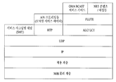
- FIG. 3 illustrates an embodiment of a protocol stack for a fixed NRT service according to the present invention.
- FIG. 4 illustrates an embodiment of a bit stream syntax structure of a virtual channel table according to the present invention
- FIG. 5 is a diagram illustrating an embodiment of a service type field value and meaning of the value in the virtual channel table of FIG. 4.
- FIG. 6 illustrates another embodiment of a value assigned to a service type field in the virtual channel table of FIG. 4 and the meaning of the value.
- FIG. 7 illustrates an embodiment of a bit stream syntax structure for an NRT service descriptor included in a virtual channel loop of the virtual channel table of FIG. 4.
- FIG. 8 illustrates an embodiment of a process of acquiring access information of an IP stream for transmitting an NRT service signaling channel using a PSI / PSIP table according to the present invention.
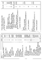
- FIG. 9 illustrates an embodiment of a bitstream syntax structure of an NST according to the present invention.
- FIG. 10 illustrates an embodiment of a value assigned to the FLUTE session type field of the NST of FIG. 9 and the meaning of the value.
- FIG. 11 illustrates an embodiment of a bit stream syntax structure for an NRT FLUTE file delivery descriptor included in the FLUTE session loop of the NST of FIG.
- FIG. 12 illustrates an embodiment of a bit stream syntax structure for an NRT media object related descriptor included in the FLUTE session loop of the NST of FIG.
- FIG. 13 is a diagram illustrating an embodiment of a value assigned to an object_association_type field of the NRT media object association descriptor of FIG. 12 and the meaning of the value.
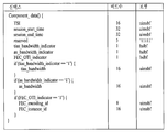
- 16 illustrates an embodiment of a bit stream syntax structure of component_descriptor () according to the present invention.
- FIG. 17 illustrates an embodiment of a bit stream syntax structure of FLUTE file delivery data using component_descriptor () of FIG. 16.
- FIG. 18 illustrates an embodiment of a bit stream syntax structure of media object related information data using component_descriptor () of FIG. 16.
- FIG. 19 illustrates another embodiment of a bit stream syntax structure of media object related information data using component_descriptor () of FIG. 16.
- FIG. 20 is a flowchart illustrating an embodiment of a process of receiving an IP stream for transmitting an NRT service signaling channel according to the present invention.
- 21 is a flowchart illustrating an embodiment of a process of receiving an NRT service according to the present invention.
- NCT NRT content table
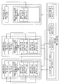
- FIG. 23 is a block diagram showing an embodiment of a receiving system for a fixed NRT service according to the present invention.
- FIG. 24 illustrates an embodiment of a protocol stack for a mobile NRT service according to the present invention.
- 25 is a diagram illustrating an embodiment of a structure of a data group according to the present invention.
- 26 illustrates a structure of an RS frame including a mobile NRT service according to an embodiment of the present invention.
- FIG. 27 is a diagram illustrating an example of an M / H frame structure for transmitting / receiving mobile service data according to the present invention
- FIG. 28 is a diagram illustrating a data transmission structure in a physical layer according to an embodiment of the present invention, and shows an example in which FIC data is included and transmitted in each data group.
- 29 illustrates a hierarchical signaling structure according to an embodiment of the present invention.
- FIG. 30 is a view showing an embodiment of a bit stream syntax structure of an SMT section according to the present invention
- FIG. 31 is a block diagram showing an embodiment of a receiving system for a mobile NRT service according to the present invention.
- the present invention is intended to receive and service a broadcast service in non real time (NRT) through a medium such as terrestrial wave, cable, or the like.
- NRT non real time
- a broadcast service will be referred to as an NRT service
- the broadcast service data will be referred to as NRT service data.
- the received NRT service data is stored in the storage medium, and then displayed on the display device according to a preset time or a user's request.
- the NRT service data is received in a file form and stored in a storage medium.
- the storage medium is an internal HDD mounted in a broadcast receiving device.
- the storage medium may be a USB (Universal Serial Bus) memory or an external HDD connected to the outside of the broadcast receiving device.
- NRT service signaling information is required to receive files constituting the NRT service and store them in a storage medium.
- this is referred to as NRT service signaling information or NRT service signaling data.
- the NRT service according to the present invention can be largely classified into a fixed NRT service and a mobile NRT service.
- fixed NRT service will be described first, followed by mobile NRT service.
- the file-type NRT service is IP packetized in an IP layer and then transmitted in a MPEG-2 TS format through a specific virtual channel.
- MPEG-2 based Program Specific Information (PSI) / Program and System Information Protocol (PSIP) table for example, whether a NRT service exists in a virtual channel through a virtual channel table (VCT), and According to an embodiment of the present invention, signaling identification information of the NRT service is performed.
- PSI Program Specific Information
- PSIP Program and System Information Protocol
- an NRT service signaling channel for transmitting NRT service signaling data signaling access information of an IP-based NRT service is IP packetized to a specific IP stream in an IP layer and then transmitted in an MPEG-2 TS form. Shall be.
- RT real-time
- NRT non-real time
- the non-real-time service is a service that receives and stores NRT service data transmitted in non-real time using extra bandwidth among some broadcast channels, particularly broadcast channels, and provides the user when necessary, and has a low transmission rate for the NRT service. Therefore, the NRT service is mainly used for storage and playback rather than real time viewing.
- the real-time service is a broadcast service that receives broadcast service data in real time and provides it to a user as in the current terrestrial broadcast.
- a broadcast station may transmit broadcast service data in real time, and may transmit news clips, weather information, advertisements, Push VODs, and the like in non real time.
- the NRT service may be news scenes, weather information, advertisements, push VOD, as well as specific scenes of a live broadcast stream.
- Conventional broadcast receivers ie, legacy devices
- the broadcast receiver (ie, NRT device) according to the present invention may provide various services by combining non-real-time services and real-time services.
- one NRT service according to the present invention includes one or more contents (or NRT contents) as shown in FIG. 2, and one content includes one or more files.
- contents or NRT contents
- files and objects are used in the same sense.
- the NRT content is a minimum unit that can be played independently. For example, if there is news provided in non-real time, and the news includes economic news, political news, and life news, the news may be referred to as an NRT service. It may be referred to as NRT content. Each of the economic news, political news, and life news is composed of at least one file.
- the NRT service may be transmitted in the form of an MPEG-2 transport stream (TS) packet through the same broadcast channel or dedicated broadcast channel as the RT service.
- TS transport stream
- IP-based NRT service data is transmitted through MPEG-2 TS packetization.
- NRT service signaling data necessary for receiving the NRT service data is transmitted through an NRT service signaling channel.
- the NRT service signaling channel is transmitted through a specific IP stream on an IP layer.
- the IP stream is also transmitted in an MPEG-2 TS packet.
- NRT service signaling data transmitted through the NRT service signaling channel provides access information of NRT services running in an IP layer.
- the broadcasting station packetizes NRT content / files according to a file transfer protocol scheme as shown in FIG. 3, and packetizes the NRT content / files according to ALC / LCT (Asynchronous Layered Coding / Layered Coding Transport) scheme.
- the packetized ALC / LCT data is again packetized according to the UDP scheme, and the packetized ALC / LCT / UDP data is again packetized according to the IP scheme to be ALC / LCT / UDP / IP data.
- the packetized ALC / LCT / UDP / IP data is referred to as an IP datagram for convenience of description in the present invention.
- NRT service signaling information necessary for receiving the NRT content / files is transmitted through an NRT service signaling channel, wherein the NRT service signaling channel is packetized according to a User Datagram protocol (UDP) scheme, and the packetized UDP data Is again packetized according to the IP method to become UDP / IP data.
- UDP User Datagram protocol
- the UDP / IP data is also called an IP datagram for convenience of explanation.
- the NRT service signaling channel is encapsulated in an IP datagram having a well-known IP desiccation address and a well-known desiccation UDP port number and multicasted.
- IP datagrams of the NRT service and the NRT service signaling channel are encapsulated in an addressable section structure, and packetized into an MPEG-2 TS format. That is, one addressable section structure has a form in which a section header and a CRC checksum are additionally added to one IP datagram.
- the form of the addressable section structure is a structure that conforms to the Digital Storage Media Command and Control (DSM-CC) section format for private data transmission. Therefore, the addressable section may also be referred to as a DSM-CC addressable section.
- DSM-CC Digital Storage Media Command and Control
- the addressable section may also be referred to as a DSM-CC addressable section.
- a 4-byte MPEG header is added to each of 184 bytes, thereby producing 188 bytes of MPEG-2 TS packets.
- the value assigned to the PID of the MPEG header is a unique value for identifying the TS packet for transmitting the NRT service and the NRT service signaling channel.
- program specific information (PSI) and program and system information protocol (PSIP) table section data are also MPEG-2 TS packets.
- the PSI table includes a Program Map Table (PMT), a Program Association Table (PAT), and the like
- the PSIP table includes, in an embodiment, a virtual channel table (VCT), a system time table (STT), and an RRT.
- VCT virtual channel table
- STT system time table
- RRT RRT
- ETT Extended Text Table
- DCCT Direct Channel Change Table
- DCCSCT Direct Channel Change Selection Code Table
- EIT Event Information Table
- MTT Master Guide Table
- the MPEG-2 TS packets are modulated by a predetermined transmission scheme, for example, a VSB transmission scheme, in a physical layer and transmitted to a receiving system.
- a predetermined transmission scheme for example, a VSB transmission scheme
- whether or not to transmit an NRT service is signaled through a PSI / PSIP table.
- a PSI / PSIP table For example, signaling whether to transmit the NRT service to a virtual channel table (VCT) is an embodiment.
- VCT virtual channel table
- VCT virtual channel table
- the VCT section transmits information on a virtual channel, for example, channel information for channel selection and packet identifier (PID) for receiving audio and / or video.
- PID packet identifier
- the syntax of the VCT section includes at least one of table_id field, section_syntax_indicator field, private_indicator field, section_length field, transport_stream_id field, version_number field, current_next_indicator field, section_number field, last_section_number field, protocol_version field, num_channels_in_section field.
- the syntax of the VCT section further includes a first loop of a 'for' loop (that is, a virtual channel loop) that is repeated by the value of the num_channels_in_section field, in which the short_name field, major_channel_number field, minor_channel_number field, modulation_mode field a second loop with a 'for' loop that repeats as many times as the number of descriptors included in the first loop, carrier_frequency field, channel_TSID field, program_number field, ETM_location field, access_controlled field, hidden field, service_type field, source_id field, descriptor_length field, and this first loop. It comprises at least one of.
- the second loop is referred to as a first descriptor loop for convenience of description.
- Descriptor descriptors () included in the first descriptor loop are descriptors individually applied to each virtual channel.
- the VCT section syntax may further include an additional_descriptor_length field and a third loop that is a 'for' loop that is repeated by the number of descriptors added to the VCT section.
- the third loop is called a second descriptor loop.
- the descriptor additional_descriptors () included in the second descriptor loop is a descriptor commonly applied to all virtual channels described in the VCT section.
- the table_id field indicates a unique identifier (ID) for recognizing that information transmitted to the table is a VCT. That is, the table_id field indicates a value indicating that the table to which this section belongs is a VCT. For example, 0xC8 may be assigned.
- the version_number field indicates a version value of the VCT
- the section_number field indicates a number of this section
- the last_section_number field indicates a number of the last section of the complete VCT.
- the num_channels_in_section field designates the number of all virtual channels existing in the VCT section.
- the short_name field in the first loop of the 'for' loop indicates a virtual channel name
- the major_channel_number field indicates a 'major' channel number associated with a virtual channel defined in the first loop
- the minor_channel_number field is' Minor 'channel number. That is, each virtual channel number should be connected to major and minor channel numbers, and the major and minor channel numbers serve as a user reference number for the corresponding virtual channel.
- the program_number field indicates to connect a virtual channel in which an MPEG-2 Program Association Table (PAT) and a Program Map Table (PMT) are defined, and corresponds to a program number in the PAT / PMT.
- PAT describes the components of the program for each program number, and indicates the PID of the transport packet for transmitting the PMT.
- the PMT describes a PID list and accessory information of a transport packet to which a program identification number and individual bit strings such as video and audio constituting the program are transmitted.
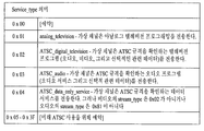
- the service_type field is a field indicating a service type in a corresponding virtual channel.
- the virtual channel may include both at least one RT service and at least one NRT service including audio and / or video.
- a service type value may be allocated as shown in FIG. 5, and may indicate that an NRT service is transmitted through the virtual channel using 0x04 indicating an ATSC data only service.
- the virtual channel may include only one or more NRT services.
- 0x05 may be newly defined as a service_type field value and may indicate that an NRT service is transmitted to the virtual channel.
- the source_id field represents a program source connected to the corresponding virtual channel.
- the source refers to one specific source such as image, text, data or sound.
- the source_id field value has a unique value in the transport stream for transmitting the VCT.
- a service loop descriptor may be included in a descriptor loop (descriptor ⁇ ) in a next loop of a 'for' loop.
- the service location descriptor may include a stream type, an Elementary_PID, a language code field, and the like for each elementary stream.
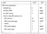
- FIG. 7 illustrates an embodiment of a syntax structure of an NRT service descriptor (NRT_service_descriptor ()) transmitted by being included in a first descriptor loop of the VCT when the service_type field indicates that an NRT service is transmitted through a corresponding virtual channel. .
- NRT_service_descriptor () is applied only to a corresponding virtual channel and provides identification information of NRT services included in the corresponding virtual channel.
- the descriptor_tag field is a descriptor identifier, and an identifier for identifying an NRT service descriptor may be set.
- the descriptor_length field represents the remaining length of the descriptor in byte units from the descriptor_length field to the end of this descriptor.
- the num_NRT_services field may allocate 8 bits in one embodiment, and indicates the number of NRT services included in this virtual channel. Thereafter, a 'for' loop is performed for the number of NRT services corresponding to the num_NRT_services field value to display identification information of each NRT service included in the virtual channel. That is, the 'for' loop may include an NRT_service_id field, an NRT_service_short_name field, an NRT_service_category field, and an NRT_service_status field.
- the NRT_service_id field allocates 16 bits and indicates a value capable of uniquely identifying the corresponding NRT service in the virtual channel (A 16-bit unsigned integer number that shall uniquely identify this NRT service within the scope of this virtual channel.).
- the NRT_service_short_name field indicates a short name of the NRT service. If there is no short name of the NRT service, the field may be filled with a null value.
- the NRT_service_category field allocates 5 bits and indicates a service type transmitted by the NRT service.
- the NRT_service_status field allocates 2 bits in one embodiment and indicates the state of the NRT service. For example, when the upper bit of the NRT_service_status field value is set to 1, the corresponding NRT service is in an active state, and when it is set to 0, it is inactive. If the lower bit of the NRT_service_status field value is set to 1, the NRT service is hidden and if it is set to 0, the most significant bit shall indicate whether this NRT service is active (when set to 1). or inactive (when set to 0) and the least significant bit shall indicate whether this NRT service is hidden (when set to 1) or not (when set to 0).).
- FIG. 8 is a diagram illustrating a system for receiving and servicing an NRT service using an ATSC A / 90 standard for delivering a data broadcast stream and an ATSC A / 92 standard for transmitting an IP multicast stream in a reception system according to the present invention. The method is explained.
- information on the streams constituting each virtual channel is signaled to the service location descriptor of the VCT or the ES_loop of the PMT.
- the service type of the VCT is 0x02 (i.e., digital A / V / Data) or 0x04 (i.e., data only), as in FIG. 5 or 6, or 0x05 (i.e., NRT Only). service)
- an NRT service stream may be transmitted through the virtual channel.
- 0x95 that is, DST transmission
- the DST is used to identify an NRT application (ie, an NRT service).
- the App_id_descrption field of the DST defines the format and interpretation of subsequent application identification bytes.
- '0x0003' is allocated to the App_id_descrption field to identify an NRT application.
- the next Application_id_byte value becomes a Service ID value of the NRT application.
- the service ID for the NRT application may have a URI value that uniquely identifies the service.
- the PID of the MPEG-2 TS packet divided from the IP datagram of the NRT service signaling channel is found through the tap information. Then, an IP datagram transmitting an NRT service signaling channel can be obtained from MPEG-2 TS packets having PIDs found through the tap information, and NRT service signaling data can be obtained from the obtained IP datagram. .
- the IP access information of the NRT service signaling channel well-known IP access information, that is, a well-known IP address and a well-known UDP port number may be used.
- an IP stream that is, an IP packet is received by accessing the IP multicast address (or address range), and NRT service signaling data is extracted from the received IP packet.
- NRT service data that is, NRT content / files may be received and stored in a storage medium or displayed on a display device.
- the NRT service may be signaled using a new value, for example, 0x96 instead of 0x95 in the Stream Type field value of the DST.
- a new value for example, 0x96 instead of 0x95 in the Stream Type field value of the DST.
- the NRT service signaling data transmitted through the NRT service signaling channel includes an NRT service map table (NST) that provides access information of an NRT service.
- NST NRT service map table
- the NST has a table form similar to the MPEG-2 private section form.
- the NST may provide access information of IP-based NRT services included in one virtual channel.
- the NST may provide access information of each FLUTE sessions configuring one NRT service.
- the NST may provide information necessary for rendering of contents / files of an NRT service transmitted through a FLUTE session.
- the NST may provide container information necessary for rendering of content / files transmitted in each FLUTE session.
- the NST may provide encoding information (eg, media / codec type) required for rendering of content / files transmitted in each FLUTE session.
- the NST may provide a decoding parameter of media required for rendering of content / files transmitted in each FLUTE session.
- the NRT service signaling data may further include a signaling table other than the NST.
- the IP datagrams of the NRT service signaling channel have the same well-known IP address and well-known UDP port number. Therefore, the classification of the NST included in the NRT service signaling data is made by a table identifier. That is, the table identifier may be table_id existing in the header of the table or the table section, and may be distinguished by further referring to table_id_extension if necessary.
- one NST consists of one section or a plurality of sections may be known through a table_id field, a section_number field, a last_section_number field, and the like in the NST section.
- a corresponding table may be completed. For example, collecting sections with table identifiers assigned to the NST can complete the NST.
- FIG. 9 is a diagram illustrating an embodiment of a bit stream syntax structure for an NST section according to the present invention. A detailed description of each field of the NST section is as follows.
- a table_id field (8 bits) is an identifier of a table, and an identifier for identifying an NST may be set.
- 0xDF is allocated to the table_id field to identify the NST.
- a section_syntax_indicator field (1 bit) is an indicator that defines the section format of the NST.
- the private_indicator field (1 bit) indicates whether the NST follows the private section.
- a section_length field (12 bits) indicates a section length of NST.
- the NST may allocate a 16-bit source_id field at a table_id_extension field position, and may be used as one of a table identifier for distinguishing the NST when the NST is received through an NRT service signaling channel.
- a version_number field (5 bits) represents the version number of the NST.
- a current_next_indicator field (1 bit) indicates whether information included in the corresponding NST section is currently applicable information or future applicable information.
- a section_number field (8 bits) indicates a section number of the current NST section.
- the last_section_number field (8 bits) indicates the last section number of the NST.
- NST_protocol_version An 8-bit unsigned integer field whose function is to allow, in the future, the NST_protocol_version field (8 bits) tells the protocol version to allow NST to transfer parameters with different structures than those defined in the current protocol. This NRT Service Map Table to carry parameters that may be structured differently than those defined in the current protocol.At present, the value for the NST_protocol_version shall be zero.Non-zero values of NST_protocol_version may be used by a future version of this standard to indicate structurally different tables.)
- a transport_stream_id field (16 bits) means a unique identifier of a broadcast stream in which a corresponding NST section is transmitted.
- a Num_NRT_services field (8 bits) indicates the number of NRT services included in the NRT section. (This 8 bit field shall specify the number of NRT Services in this NST section.)
- a 'for' loop (or NRT service loop) is performed as many as the number of NRT services corresponding to the num_NRT_services field value to provide signaling information for a plurality of NRT services. That is, signaling information of the corresponding NRT service is displayed for each NRT service included in the NST section. In this case, the following field information may be provided for each NRT service.
- the NRT_service_id field (16 bits) indicates a value that can uniquely identify the NRT service (A 16-bit unsigned integer number that shall uniquely identify this NRT service within the scope of this NRT section.).
- the value of the NRT_service_id field of one service does not change while the service is maintained.
- the NRT_service_id field value of that service may not be used until a certain amount of time has elapsed (The NRT_service_id of a service shall not change throughout the life of the service.To avoid confusion , it is recommended that if a service is terminated, then the NRT_service_id for the service should not be used for another service until after a suitable interval of time has elapsed.).
- An NRT_service_category field (5 bits) indicates a service type of a corresponding NRT service.
- An NRT_service_status field (2 bits) indicates the state of a corresponding NRT service. For example, when the upper bit of the NRT_service_status field value is set to 1, the corresponding NRT service is in an active state, and when it is set to 0, it is inactive. If the lower bit of the NRT_service_status field value is set to 1, the NRT service is hidden and if it is set to 0, the most significant bit shall indicate whether this NRT service is active (when set to 1). or inactive (when set to 0) and the least significant bit shall indicate whether this NRT service is hidden (when set to 1) or not (when set to 0).).
- An SP_indicator field (1 bit) represents whether service protection of a corresponding NRT service is performed. If the value of the SP_indicator field is 1, service protection is applied to at least one of the components required to provide a meaningful presentation of the NRT service (A 1-bit field that indicates, when set to 1, service). protection is applied to at least one of the components needed to provide a meaningful presentation of this NRT Service).
- a Short_NRT_service_name field (8 * 8 bits) indicates a short name of the NRT service. If there is no short name of the NRT service, the field may be filled with a null value (eg, 0x00).
- a num_FLUTE_sessions field (8 bits) indicates the number of FLUTE sessions constituting the NRT service.
- a 'for' loop (or FLUTE session loop) is performed as many as the number of FLUTE sessions corresponding to the num_FLUTE_sessions field value to provide access information for a plurality of FLUTE sessions. That is, access information of the corresponding FLUTE session is provided for each FLUTE session included in the NRT service. In this case, the following field information may be provided for each FLUTE session.
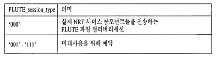
- a FLUTE_session_type field (3 bits) identifies the type of FLUTE session according to the data objects transmitted in the FLUTE session. 10 illustrates the allocation of the FLUTE_session_type field value and its meaning. For example, if the FLUTE_session_type field value is 000, this indicates that the FLUTE session is a FLUTE file delivery session for transmitting content / file for an actual NRT service. The remaining values are not used in the present invention. That is, when the FLUTE_session_type field value is 000, the FLUTE file delivery descriptor (NRT_FLUTE_File_Delivery_descriptor ()) as shown in FIG. 11 is transmitted as FLUTE_session_level_descriptor (). Each field description of the FLUTE file delivery descriptor will be described later.
- a media_object_association_indicator field (1 bit) indicates whether media object association information related to the FLUTE session is present. For example, when the media_object_association_indicator field is set to 1, it indicates that there is a descriptor (for example, NRT_media_object_association_descriptor ()) or media object related information provided in a stream or file in association with the FLUTE session (This 1- bit indicator that shall indicate, when set, that there is media object association information is provided associated with this FLUTE session, by the media_object_association_descriptor () or by a stream or a file.). That is, if the field is 1, NRT_media_object_association_descriptor () is included in the FLUTE session loop and received.
- a descriptor for example, NRT_media_object_association_descriptor ()
- the media_object_association_indicator field may be omitted from the NST.
- NRT_media_object_association_descriptor () is received as the FLUTE session level descriptor.
- the receiver parses all descriptors included in the FLUTE session level descriptor.
- the identifier of the descriptor may identify NRT_media_object_association_descriptor ().
- the essential_component_delivery_indicator field (1 bit) is set to '1', this indicates that the corresponding FLUTE session transmits an essential component (ie, content / file) for an NRT service. Otherwise, this field indicates that this FLUTE session carries an essential component for the NRT (i.e. content / file). service.Otherwise, this field indicates that the components carried through this FLUTE session are optional components.).
- IP_version_flag field (1 bit) indicates that the FLUTE_session_source_IP_address and FLUTE_session_destination_IP_address fields are IPv4 addresses, and when set to '1', indicates that the FLUTE_session_source_IP_address and FLUTE_session_destination_IP_address fields are IPv6 addresses (A 1-bit indicator, when set to zero, shall indicate that FLUTE_session_source_IP_address, FLUTE_session_destination_IP_address fields are IPv4 addresses.Otherwise, this field indicates that FLUTE_session_source_IP_address, FLUTE_session_destination_IP_address fields are IPv6 addresses.).
- the FLUTE_session_source_IP_address field (32 or 128 bits) exists when the source_specific_multicast_flag field is set to '1', but does not exist when the source_specific_multicast_flag field is set to '0'. This field shall be present if source_specific_multicast_flag is set to '1', and shall not be present if source_specific_multicast_flag is set to '0 if present. If present, this field shall contain the source IP address of all the IP datagrams carrying the components of this FLUTE session.).
- the field shall contain the destination of all the IP datagrams carrying the components of this FLUTE session. (32 or 128 bits). ).
- FLUTE_session_destination_UDP_port_num field (16 bits) indicates a destination UDP port number of the UDP / IP stream carrying the FLUTE session (A 16-bit unsigned integer field, that represents the destination UDP port number for the UDP / IP stream carrying this FLUTE session.).
- a Num_FLUTE_session_level_descriptors field (4 bits) indicates the number of descriptors (FLUTE_session_level_descriptor ()) included in the FLUTE session loop.
- FLUTE_session_level_descriptor () is included in the FLUTE session loop by the number corresponding to the Num_FLUTE_session_level_ descriptors field value to provide additional information about the FLUTE session (One or more descriptors providing additional information for this FLUTE session, may be included.) .
- a Num_NRT_service_level_descriptors field (4 bits) indicates the number of descriptors (NRT_service_level_descriptors ()) included in an NRT service loop.
- NRT_service_level_descriptors are included in the NRT service loop as many as the number corresponding to the Num_NRT_service_level_descriptors field value (Zero or more descriptors providing additional information for this NRT service, may be included.).
- NRT_FLUTE_File_Delivery_descriptor () provided as FLUTE_session_level_descriptor () according to the present invention. That is, NRT_FLUTE_File_Delivery_descriptor () is used as one of NUTE FLUTE_session_level_descriptor () and includes additional signaling information for accessing the FLUTE session.
- the NRT_FLUTE_File_Delivery_descriptor () is received as a FLUTE session level descriptor when the FLUTE_session_type field value is 000. Description of each field of the NRT_FLUTE_File_Delivery_descriptor () is as follows.
- a descriptor_tag field (8 bits) is a descriptor identifier, and an identifier for identifying the NRT FLUTE file delivery descriptor NRT_FLUTE_File_Delivery_descriptor () may be set.
- a descriptor_length field (8 bits) indicates the remaining length of the descriptor in byte units from the descriptor_length field to the end of this descriptor.
- a FLUTE_session_TSI field (16 bits) indicates the TSI of the FLUTE session. That is, the TSI is an identifier capable of uniquely identifying the FLUTE session (A 16-bit unsigned integer field, which shall be the Transport Session Identifier (TSI) of the FLUTE session).
- TSI Transport Session Identifier
- a session_start_time field (16 bits) indicates the time at which the FLUTE session starts. If the value of this field is all '0', the FLUTE session may be interpreted as already started (If the value of this field is set to all zero, then it shall be interpreted to mean that the session has already started).
- a session_end_time field (16 bits) indicates the time when the FLUTE session ends. If the value of the field is all '0', the FLUTE session may be interpreted to continue indefinitely (session_end_time: The time at which the FLUTE session ends.If the value of this field is set to all zero, then it shall be interpreted to mean that the session continues indefinitely).
- a tias_bandwidth_indicator field (1 bit) indicates whether TIAS (Transport Independent Application Specific) bandwidth information is included. If the TIAS bandwidth field is indicated to exist, the bit must be set to '1', and if the TIAS bandwidth field is indicated to not exist, the bit must be set to '0' (A 1-bit field that flags the inclusion of TIAS bandwidth information.This bit shall be set to '1' to indicate the TIAS bandwidth field is present, and it shall be set to '0' to indicate the TIAS bandwidth field is absent).
- TIAS Transport Independent Application Specific
- An as_bandwidth_indicator field (1 bit) indicates whether or not Application Specific (AS) bandwidth information is included. If the AS bandwidth field is present, the corresponding bit must be set to '1'. If the AS bandwidth field is indicated that it is not present, this bit must be set to '0' (A 1-bit field that flags). the inclusion of AS bandwidth information.This bit shall be set to '1' to indicate the AS bandwidth field is present, and it shall be set to '0' to indicate the AS bandwidth field is absent).
- AS Application Specific
- An FEC_OTI_indicator field (1 bit) indicates whether or not the FEC object transmission information (OTI) is provided (A 1-bit indicator that indicates whether FEC Object Transmission Information is provided).
- a tias_bandwidth field (16 bits) is present when the as_bandwidth_indicator field is set to '1' and indicates a TIAS maximum bandwidth (This value shall be one one-thousandth of the Transport Independent Application Specific maximum bandwidth as defined in RFC 3890, rounded up to the next highest integer if necessary.This gives the TIAS bandwidth in kilobits per second).
- An as_bandwidth field (16 bits) is present when the as_bandwidth_indicator field is set to '1' and indicates an AS maximum bandwidth (This value shall be the Application Specific maximum bandwidth as defined in RFC 4566. This gives the AS bandwidth in kilobits per second).
- the FEC_encoding_id field exists when the FEC_OTI_indicator field is set to '1' and indicates an FEC encoding ID used in the FLUTE session (FEC encoding ID used in this FLUTE session, as defined in RFC 3926).
- the FEC_instance_id field exists when the FEC_OTI_indicator field is set to '1' and indicates an FEC instance ID used in the FLUTE session (FEC instance ID used in this FLUTE session, as defined in RFC 3926).
- files constituting the NRT service by opening the corresponding FLUTE session according to the time information set by the session_start_time field and the session_end_time field, and an FDT (File DescriptioN Table) describing signaling information of the files may be received.
- media_object_association_indicator field value is set to 1 in the NST
- media object related information related to the FLUTE session is signaled using an NRT media object related descriptor.
- the media object related information is provided in the form of text represented by a Multipurpose Internet Mail Extensions (MIME) type.
- MIME Multipurpose Internet Mail Extensions
- NRT_media_object_association_descriptor () according to the present invention.
- the NRT media object related descriptor is used as one of FLUTE_session_level_descriptor () of NST.
- the NRT media object related descriptor signals parameters necessary for rendering of a content / file (or media object / file) transmitted through a corresponding FLUTE session.
- NRT_media_object_association_descriptor () Description of each field of the NRT media object related descriptor NRT_media_object_association_descriptor () is as follows.
- a descriptor_tag field (8 bits) is a descriptor identifier, and an identifier for identifying the NRT media object association descriptor NRT_media_object_association_descriptor () is indicated.
- a descriptor_length field (8 bits) indicates the remaining length of the descriptor in byte units from the descriptor_length field to the end of this descriptor.
- An object_association_type field (3 bits) indicates how the media object association information is signaled (This 3-bit enumerated field shall indicate how the media object association information is signaled.).
- the media object related information may be signaled through an in-line field of the descriptor in the form of a text of a MIME type.
- the media object association information may be signaled through a media object association stream in the form of text of a MIME type.
- the media object association information may be signaled through a media object association file in the form of a text of a MIME type (The media object association can be done through the in-line fields of this descriptor or can be done through the media object association stream or through the media object association file.).
- FIG. 13 illustrates an embodiment of values assigned to the object_association_type field and definitions of the values.
- the media object association information required for rendering the content transmitting the related object is provided as in-line text of the descriptor (The media object association information, which are necessary for rendering the content that the associated object is carrying, is provided as in-line text of this descriptor.).
- the media object related information required for rendering the content transmitting the related object is provided as a separate UDP / IP stream.
- the media object association information, which are necessary for rendering the content that the associated object is carrying, is provided by a separated UDP / IP stream, which carries SAP / SDP like data structure.).
- the media object related information required for rendering the content transmitting the related object is provided in a file such as SDP.
- the media object association information, which are necessary for rendering the content that the associated object is carrying, is provided by a SDP-like file, which is carried through a separated FLUTE file delivery session.).
- the media object association information is directly described using at least one field in the NRT media object association descriptor.
- the NRT media object association descriptor provides access information of a stream or file for transmitting the media object association information. If the object_association_type field value is '010', the NRT media object related descriptor provides not only file access information but also parameters required for reception of a FLUTE session for transmitting the file.
- the NRT media object related descriptor includes a num_media_objects_in_session field, and a for loop iteration that is repeated as many as the number corresponding to the num_media_objects_in_session field value.
- the for loop loop may include a media_object_TOI field, an object_container_type_text_length field, an object_container_type_text () field, an object_media_type_text_length field, an object_media_type_text () field, an object_decoding_parameters_text_length field, and an object_decoding_parameters_text ().
- the num_media_objects_in_session field (8 bits) indicates the number of media objects that require object related signaling in the FLUTE session (This 8-bit unsigned integer field specifies the number of media objects that need the object association signaling, carried through this FLUTE session .).
- the media_object_TOI field (32 bits) indicates a Transport Object Identifier (TOI) of a transport object transmitted through the FLUTE session (This 32-bit unsigned integer field which shall be the Transport Object Identifier, associated with this Transport Object carried throught the FLUTE session.). That is, the media_object_TOI field indicates a value for identifying a content / file transmitted through the FLUTE session.
- TOI Transport Object Identifier
- the field_container_type_text_length field (8 bits) indicates the byte length of the object_container_type_text () character string. (This field shall specify the length (in bytes) of the object_container_type_text () character string.)
- the object_container_type_text () field indicates a file or object container type in which the object is encapsulated in text form. In other words, the file or object container type where this object is encapsulated.Expressed in string that would normally appear as an entry in an SDP to identify the type of the container.).
- the object_container_type_text () field indicates a file format and the like in text form.
- the field_media_type_text_length field (8 bits) indicates the byte length of the object_media_type_text () character string. (This field shall specify the length (in bytes) of the object_media_type_text () character string.).
- the object_media_type_text () field indicates a media type for identifying an encoding format of an object described in this descriptor.
- the object_media_type_text () field provides encoding format information such as audio and video transmitted to an NRT service in text form.
- the field_decoding_parameters_text_length field (8 bits) indicates the byte length of the object_decoding_parameters_text () character string. (This field shall specify the length (in bytes) of the object_decoding_parameters_text () character string.).
- the object_decoding_parameters_text () field indicates the decoding parameters of the object described by this descriptor in text form (A text string that identifies the decoding parameters of the object that this descriptor describes.).
- the descriptor may include an IP_version_flag field, a source_specific_multicast_flag field, an object_association_stream_source_IP_address field, an object_association_stream_destination_UDP_port_num field, and an object_association_stream_destination_IP_address field. That is, the descriptor provides access information of an IP datagram that transmits the file or stream.
- the object_association_stream_source_IP_address, object_association_stream_ destination_IP_address fields are IPv4 addresses, and if the IP_version_flag field is set to '0', the object_association_stream_source_IP_address and object_association_stream_destination_IP_address fields are IPv6 address fields.
- object_association_stream_source_IP_address, object_association_stream_ destination_IP_address fields are IPv4 addresses.Otherwise, this field indicates that object_association_stream_source_IP_address, object_association_stream_destination_IP_address fields are IPv6 addresses.).
- the source_specific_multicast_flag field (1 bit), if set to '1', indicates that the source specific multicast is used for the FLUTE session. Therefore, in this case, object_association_stream_source_IP_address must exist (A-1bit Boolean flag that shall indicate, when set, that the source specific multicast is used for this FLUTE session. Thus, the object_association_stream_source_IP_address shall be present.).
- the object_association_stream_IP_address field (32 or 128 bits) exists when the source_specific_multicast_flag field is set to '1', but does not exist when the source_specific_multicast_flag field is set to '0'. If present, this field contains the source IP address of all IP datagrams carrying the components (i.e. content / files) of the FLUTE session. (This field shall be present if source_specific_multicast_flag is set to '1' and shall not be present if source_specific_multicast_flag is set to '0'.If present, this field shall contain the source IP address of all the IP datagrams carrying the components of this FLUTE session.).
- the object_association_stream_destination_IP_address field (32 or 128 bits) indicates a destination IP address of all IP datagrams carrying a component (i.e., content / file) of the object related stream (This field shall contain the destination of all the IP datagrams. carrying the components of this object association stream.).
- the object_association_stream_destination_UDP_port_num field (16 bits) indicates a destination UDP port number of a UDP / IP stream carrying the object related stream (A 16-bit unsigned integer field, that represents the destination UDP port number for the UDP / IP stream carrying this object association stream.).
- the descriptor may include an object_association_session_TSI field, an object_association_session_start_time field, an object_asso_ation_session_end_time field, a tias_bandwidth_indicator field, a FEC_OTI_indicator field, an FAS_id_band field, an _as_id_band field, an _as_id_band field That is, the descriptor describes parameters required for receiving the corresponding FLUTE session.
- the object_association_session_TSI (16 bits) indicates a TSI of a FLUTE session for transmitting the object association file. That is, the TSI is an identifier capable of uniquely identifying the FLUTE session (A 16-bit unsigned integer field, which shall be the Transport Session Identifier (TSI) of the FLUTE session that carries the object association file.)
- TSI Transport Session Identifier
- the object_association_session_start_time (16 bits) indicates the time at which the FLUTE session for transmitting the object association file starts. If the value of this field is set to all- the time at which the FLUTE session that carries the object association file starts. zero, then it shall be interpreted to mean that the session has already started.).
- the object_association_session_end_time field (16 bits) indicates the time when the FLUTE session for transmitting the object association file ends. (The time at which the FLUTE session that carries the object association file ends.If the value of this field is set to all zero , then it shall be interpreted to mean that the session continues indefinitely.).
- the tias_bandwidth_indicator field (1 bit) indicates whether TIAS (Transport Independent Application Specific) bandwidth information is included. If the TIAS bandwidth field is indicated to exist, the bit must be set to '1', and if the TIAS bandwidth field is indicated to not exist, the bit must be set to '0' (A 1-bit field that flags the inclusion of TIAS bandwidth information.This bit shall be set to '1' to indicate the TIAS bandwidth field is present, and it shall be set to '0' to indicate the TIAS bandwidth field is absent).
- TIAS Transport Independent Application Specific
- the as_bandwidth_indicator field (1 bit) indicates whether or not Application Specific (AS) bandwidth information is included. If the AS bandwidth field is present, the corresponding bit must be set to '1'. If the AS bandwidth field is indicated that it is not present, this bit must be set to '0' (A 1-bit field that flags). the inclusion of AS bandwidth information.This bit shall be set to '1' to indicate the AS bandwidth field is present, and it shall be set to '0' to indicate the AS bandwidth field is absent).
- AS Application Specific
- the FEC_OTI_indicator field (1 bit) indicates whether FEC object transmission information (OTI) is provided (A 1-bit indicator that indicates whether FEC Object Transmission Information is provided).
- the tias_bandwidth field (16 bits) exists when the as_bandwidth_indicator field is set to '1' and indicates a TIAS maximum bandwidth (This value shall be one one-thousandth of the Transport Independent Application Specific maximum bandwidth as defined in RFC 3890 , rounded up to the next highest integer if necessary.This gives the TIAS bandwidth in kilobits per second).
- the as_bandwidth field (16 bits) is present when the as_bandwidth_indicator field is set to '1' and indicates an AS maximum bandwidth (This value shall be the Application Specific maximum bandwidth as defined in RFC 4566. This gives the AS bandwidth in kilobits per second).
- the FEC_encoding_id field exists when the FEC_OTI_indicator field is set to '1' and indicates an FEC encoding ID used in the FLUTE session (FEC encoding ID used in this FLUTE session, as defined in RFC 3926).
- the FEC_instance_id field exists when the FEC_OTI_indicator field is set to '1' and indicates an FEC instance ID used in the FLUTE session (FEC instance ID used in this FLUTE session, as defined in RFC 3926).
- the stream when the media object related information is transmitted in the form of a stream or a file, the stream may be a Session Announcement Protocol (SAP) stream, and the file may be a Session Description Protocol (SDP) file.
- SAP Session Announcement Protocol
- SDP Session Description Protocol
- the IP_version_flag field, source_specific_multicast_flag field, object_association_stream_source_IP_address field, object_association_stream_destination_UDP_port_num field, and object_association_stream_destination_IP_address field are access information of the IP datagram transmitting the SAP stream. Accordingly, the IP datagram of the SAP stream may be received based on the access information of the IP datagram, and the media object related information may be extracted from the IP datagram of the received SAP stream.
- the IP_version_flag field, the source_specific_multicast_flag field, the object_association_stream_source_IP_address field, the object_association_stream_destination_UDP_port_num field, and the object_association_stream_destination_IP_address field transmit the FLDPgram or the corresponding IP data corresponding to the FLUTE data accessing the corresponding session data.
- the IP datagram of the SDP file may be received based on the access information of the IP datagram, and the media object related information may be extracted from the IP datagram of the received SDP file.
- the syntax is written in the form of MPEG-2 private section for the sake of understanding, but the format of the data may be in any form.
- other methods such as signaling in the form of a Session Description Protocol (SDP) and signaling through a Session Announcement Protocol (SAP) may be used.
- SDP Session Description Protocol
- SAP Session Announcement Protocol
- the table_id field (8 bits) is a field for identifying the type of the corresponding table section.
- the table section is a table section constituting the NST (An 8-bit unsigned integer number). that indicates the type of table section being defined in NRT Service Table (NST).
- the section_syntax_indicator field (1 bit) is an indicator for defining the section format of the NST.
- the section format may be, for example, a short-form syntax ('0') of MPEG (section_syntax_indicator: This 1-bit field shall be be). set to '0' to always indicate that this table is derived from the "short" form of the MPEG-2 private section table).
- the private_indicator field (1 bit) indicates whether the section type follows the private section type (private_indicator: This 1-bit field shall be set to '1').
- section_length A 12-bit field.It specifies the number of remaining bytes this table section immediately following this field.The value in this field shall not exceed 4093 (0xFFD)).
- table_id_extension This is a 16-bit field and is table-dependent.It shall be considered to be logically dependent on the table. part of the table_id field providing the scope for the remaining fields).
- the table_id_extension field includes an NST_protocol_version field.
- the NST_protocol_version field (8 bits) indicates a protocol version for allowing NST transmitted by parameters having a structure different from those defined in the current protocol (NST_protocol_version: An 8-bit unsigned integer field whose function is to allow, in the future, this NST to carry parameters that may be structured differently than those defined in the current protocol.At present, the value for the NST_protocol_version shall be zero.Non-zero values of NST_protocol_version may be used by a future version of this standard to indicate structurally different tables).
- a version_number field (5 bits) represents the version number of the NST.
- current_next_indicator A one-bit indicator, which when set to '1' shall indicate that the NST sent is currently applicable.When the bit is set to '0', it shall indicate that the table sent is not yet applicable and will be the next table to become valid. This standard imposes no requirement that "next" tables (those with current_next_indicator set to '0' must be sent.An update to the currently applicable table shall be signaled by incrementing the version_number field).
- a section_number field (8 bits) indicates the number of the current NST section. (section_number: This 8-bit field shall give the section number of this NST section. The section_number of the first section in an NST shall be '0x00'. The section_number shall be incremented by 1 with each additional section in the NST.
- last_section_number This 8-bit field shall give the number of the last section (ie, the section with the highest section_number) of the NST of which this section is a part).
- a carrier_frequency field (32 bits) indicates a transmission frequency corresponding to the channel.
- a transport_stream_id field (16 bits) means a unique identifier of a broadcast stream in which a corresponding NST section is transmitted.
- a source_id field (16 bits) indicates a programming source associated with the virtual channel.
- a num_NRT_services field (8 bits) indicates the number of NRT services in the NST section (num_services: This 8 bit field specifies the number of services in this NST section).
- a 'for' loop (or NRT service loop) is performed as many as the number of NRT services corresponding to the num_NRT_services field value to provide signaling information for a plurality of NRT services. That is, signaling information of the corresponding NRT service is displayed for each NRT service included in the NST section. In this case, the following field information may be provided for each NRT service.
- NRT_service_status field (2 bits) identifies the state of the corresponding NRT service.
- the MSB indicates whether the corresponding NRT service is active ('1') or inactive ('0'), and the LSB indicates whether the corresponding NRT service is hidden ('1') or not ('0').
- NRT_service_status A 2-bit enumerated field that shall identify the status of this NRT Service. The most significant bit shall indicate whether this NRT Service is active (when set to '1') or inactive (when set to '0') and the least significant bit shall indicate whether this NRT Service is hidden (when set to '1') or not (when set to '0').
- Hidden services are normally used for proprietary applications, and ordinary receiving devices should ignore them).
- An SP_indicator field (1 bit) represents whether service protection of a corresponding NRT service is performed. If the value of the SP_indicator field is 1, service protection is applied to at least one of the components required to provide a meaningful presentation of the NRT service (A 1-bit field that indicates, when set to 1, service). protection is applied to at least one of the components needed to provide a meaningful presentation of this NRT Service).
- a CP_indicator field (1 bit) indicates whether content protection of a corresponding NRT service is performed. If the CP_indicator field value is 1, content protection is applied to at least one of the components required to provide a meaningful presentation of the NRT service (CP_indicator: A 1-bit field that shall indicate, when set, that content). protection is applied to at least one of the components needed to provide a meaningful presentation of this NRT Service).
- the NRT_service_id field (16 bits) indicates a value that uniquely identifies this NRT service (A 16-bit unsigned integer number that shall uniquely identify this NRT service within the scope of this NRT section.). The value of the NRT_service_id field of one service does not change while the service is maintained.
- the NRT_service_id field value of that service may not be used until a certain amount of time has elapsed (The NRT_service_id of a service shall not change throughout the life of the service.To avoid confusion , it is recommended that if a service is terminated, then the NRT_service_id for the service should not be used for another service until after a suitable interval of time has elapsed.).
- a Short_NRT_service_name field (8 * 8 bits) indicates a short name of the NRT service. If there is no short name of the NRT service, the field may be filled with a null value (eg, 0x00).
- NRT_service_category field (6 bits) identifies a type of service transmitted in the corresponding NRT service, as defined in Table 1 below (NRT_service_category: A 6-bit enumerated type field that shall identify the type of service carried in this NRT Service as defined in [Table 1].).
- a num_components field (5 bits) indicates the number of IP stream components included in the NRT service (num_components: This 5-bit field specifies the number of IP stream components in this NRT Service).
- the IP_version_flag field (1 bit) indicates that the source_IP_address field, the NRT_service_destination_IP_address field, and the component_destination_IP_address field are IPv4 addresses when set to '0', and the source_IP_address field, NRT_service_destination_IP_address field, and component_destination_IP_address field when the value is set to '1'.
- IP_version_flag A 1-bit indicator, which when set to '0' shall indicate that source_IP_address, NRT_service_destination_IP_address, and component_destination_IP_address fields are IPv4 addresses. The value of '1' for this field is reserved for possible future indication that source_IP_address, NRT_service_destination_IP_address, and component_destination_IP_address fields are for IPv6).
- a source_IP_address_flag field (1 bit) indicates that when a flag is set, a source IP address value for the corresponding NRT service exists to indicate source specific multicast (source_IP_address_flag: A 1-bit Boolean flag that shall indicate, when set , that a source IP address value for this NRT Service is present to indicate a source specific multicast).
- NRT_service_destination_IP_address_flag A 1-bit Boolean flag that indicates, when set to ' 1 'that a NRT_service_destination_IP_address value is present, to serve as the default IP address for the components of this NRT Service).
- the source_IP_address field (128 bits) has a corresponding field when source_IP_address_flag is set to '1', but the corresponding field will not exist when source_IP_address_flag is set to '0'. If this field is present, this field will contain the source IP address of all IP datagrams carrying components of the NRT service.
- the limited use of the 128-bit long address in this field is intended to enable future use of IPv6, although the use of IPv6 is currently undefined.
- Source_IP_address becomes the source IP address of the same server transmitting all channels of the FLUTE session (source_IP_address: This field shall be present if the source_IP_address_flag is set to '1' and shall not be present if the source_IP_address_flag is set to '0'.If present, this field shall contain the source IP address of all the IP datagrams carrying the components of this NRT Service. The conditional use of the 128 bit-long address version of this field is to facilitate possible use of IPv6 in the future, although use of IPv6 is not currently defined).
- the NRT_service_destination_IP_address field (128 bits) has a corresponding source_IP_address field when source_IP_address_flag is set to '1', but the corresponding source_IP_address field will not exist when source_IP_address_flag is set to '0'. If the corresponding source_IP_address field does not exist, the component_destination_IP_address field will exist for each component in the num_components loop.
- the limited use of the 128-bit long address in the corresponding source_IP_address field is intended to enable the use of IPv6 in the future, although the use of IPv6 is not currently defined.
- NRT_service_destination_IP_address This field shall be present if the NRT_service_destination_IP_address_flag is set to '1' and shall not be present if the NRT_service_destflag is set '0'. If this NRT_service_destination_IP_address is not present, then the component_destination_IP_address field shall be present for each component in the num_components loop. The conditional use of the 128 bit-long address version of this field is to facilitate possible use of IPv6 in the future , although use of IPv6 is not currently defined).
- a 'for' loop (or a component loop) is performed as many as the number of components corresponding to the num_components field value to provide access information for a plurality of components. That is, it provides connection information of each component included in the NRT service. In this case, the following field information may be provided for each component.
- one component corresponds to one FLUTE session.
- the essential_component_indicator field (1 bit) indicates that the component is an essential component for the NRT service when the value of the corresponding field is set to '1'. Otherwise_component_indicator: A one-bit indicator which, when set to '1' shall indicate that this component is an essential component for the NRT Service.Otherwise, this field indicates that this component is an optional component).
- a port_num_count field (6 bits) indicates the number of UDP ports associated with the corresponding UDP / IP stream component.
- component_destination_IP_address_flag field (1 bit) is a flag indicating that a component_destination_IP_address field exists for a corresponding component when it is set to '1' (component_destination_IP_address_flag: A 1-bit Boolean flag that shall indicate, when set to '1' that the component_destination_IP_address is present for this component).
- a component_destination_IP_address field (128 bits) has a corresponding field when component_destination_IP_address_flag is set to '1', but a corresponding field will not exist when component_destination_IP_address_flag is set to '0'. If this field is present, this field will contain the source IP address of all IP datagrams carrying components of the NRT service. The limited use of the 128-bit long address in this field is intended to enable future use of IPv6, although the current use of IPv6 is not defined.
- the destination address of the IP datagrams carrying this component of the NRT Service shall match the address in this field.
- the destination address of the IP datagrams carrying this component shall match the address in the NRT_service_destination_IP_address field.
- the conditional use of the 128 bit-long address version of this field is to facilitate possible use of IPv6 in the future, although use of IPv6 is not currently defined).
- a component_destination_UDP_port_num field (16 bits) indicates a destination UDP port number for a corresponding UDP / IP stream component (component_destination_UDP_port_num: A 16-bit unsigned integer field, that represents the destination UDP port number for this UDP / IP stream component).
- a num_component_level_descriptors field (4 bits) indicates the number of descriptors that provide additional information of the component level.
- the component_level_descriptor () is included in the component loop as many as the number corresponding to the num_component_level_descriptors field value, thereby providing additional information about the component.
- a num_NRT_service_level_descriptors field (4 bits) indicates the number of descriptors that provide additional information of the NRT service level.
- NRT_service_level_descriptor () is included in the NRT service loop as many as the number corresponding to the num_NRT_service_level_descriptors field value, thereby providing additional information about the NRT service.
- the num_virtual_channel_level_descriptors field (4 bits) is the number of descriptors that provide additional information of the virtual channel level.
- virtual_channel_level_descriptor () is included in the virtual channel loop to provide additional information about the virtual channel.
- FIG. 16 shows an embodiment of a bit stream syntax structure of component_descriptor () provided as component_level_descriptors (). That is, component_descriptor () is used as one of the component level descriptor_level_descriptors () of the NST, and describes additional signaling information of the component.
- a descriptor_tag field (8 bits) is a descriptor identifier, and an identifier for identifying component_descriptor () may be set.
- a descriptor_length field (8 bits) indicates the remaining length of the descriptor in byte units from the descriptor_length field to the end of this descriptor.
- a component_type field (7 bits) indicates a value for identifying an encoding format of a component.
- the identification value may be one of values assigned for payload_type of the RTP / AVP stream. Or it may be one of the values predetermined by the appointment of the transmitting / receiving side, or may be a dynamic value between 96-127.
- the value of the component_type field must match the value in payload_type in the RTP header of the IP stream carrying the component (component_type: This 7-bit field shall identify the encoding format of the component.
- the value may be any of the values assigned by IANA for the payload_type of an RTP / AVP stream, or it may be any of the values assigned by ATSC, or it may be a "dynamic value" in the range 96-127
- the value of this field shall match the value in the payload_type field in the RTP header of the IP stream carrying this component.Note that additional values of the component_type field in the range of 43-71 can be defined in future versions of this standard).
- the component_data (component_type) field provides encoding parameters and / or other parameters necessary for rendering the component.
- the structure of the component_data element is determined by the value of the component_type field (component_data (component_type):
- the component_data () element provides the encoding parameters and / or other parameters necessary for rendering this component.
- the structure of the component_data is determined by the value of component_type field).
- the component_data (component_type) field provides component data for an H.264 / AVC video stream.
- the component_data (component_type) field provides data for FLUTE file delivery as shown in FIG. Description of each field of FIG. 17 may be omitted with reference to FIG. 11.
- signaling information necessary for receiving the corresponding FULTE session may be provided using NRT_FLUTE_File_Delivery_descriptor () of FIG. 11 or may be provided using the component_descriptor () descriptor of FIG. 16.
- a component_encryption_flag field (1 bit) indicates whether a corresponding component is encrypted.
- a num_STKM_streams field (8 bits) indicates the number of STKM streams associated with the component when the component_encryption_flag field indicates encryption (num_STKM_streams: An 8-bit unsigned integer field that shall identify the number of STKM streams associated with this component).
- An STKM_stream_id field (8 bits) indicates a value for identifying a SKTM stream which can be repeated by the value of the Num_STKM_streams field to obtain a key required for decryption.
- the media object association information may also be provided in the NST of FIGS. 14 and 15.
- NRT_media_object_association_descriptor () as shown in FIG. 12 is provided as a component level descriptor.
- the receiver parses all descriptors included in the component level descriptor.
- the identifier of the descriptor may be used to identify NRT_media_object_association_descriptor ().
- the description of each field of the NRT_media_object_association_descriptor () and the process of extracting the media object related information in the form of text from the NRT_media_object_association_descriptor () may be omitted by referring to the above-described NST description of FIG. 12.
- a media_object_association_indicator field (1 bit) may be allocated to the NST of FIGS. 14 and 15 to identify whether NRT_media_object_association_descriptor () exists in the component loop.
- media object related information may be provided using component_descriptor () as shown in FIG. 16.
- the componet_type field value may use one of values between 43 and 71.
- 43 is allocated to provide the media object related information as component data.
- the above-described numerical values are merely examples, and the scope of the present invention is not limited to the numerical values. That is, when the value of the component_type field is 43, the component_data (component_type) field provides component data for media object related information as shown in FIG. Description of each field of FIG. 17 may be omitted with reference to FIG. 12.
- the componet_type field value may be assigned to any value within a dynamic range (ie, 96-127).
- media object related information may be provided using component data as shown in FIG. 19.
- FIG. 19 illustrates an embodiment of a bit stream syntax structure of component_data () when a value in a dynamic range (ie, 96-127) is assigned as a value of the componet_type field.
- a general_media_type field (4 bits) indicates the general media type of the component.
- the encoding format and decoding parameters applied to the video stream are provided in text form using the following media_type_text () field and decoding_parameters_text () field.
- the media_type_text () field and the decoding_parameters_text () field provide an encoding format and a decoding parameter in the form of text represented by a Multipurpose Internet Mail Extensions (MIME) type.
- MIME Multipurpose Internet Mail Extensions
- the present invention may allocate 0x2 as the general_media_type field value, or assign one of 0x4 to 0xF, and provide media object related information in text form using the media_type_text () field and the decoding_parameters_text () field. .
- an ISO_639_language_code field (24 bits) indicates a language used when an audio stream is assigned 0x1 as the general_media_type field value.
- the media_type_text_length field (8 bits) indicates the byte length of the following media_type_text () character string. (This field shall specify the length (in bytes) of the media_type_text () character string.)
- the media_type_text () field indicates a media type for identifying an encoding format. That is, the encoding format of the stream corresponding to the general media type is displayed in text form.
- a decoding_parameters_text_length field (8 bits) indicates the byte length of the following decoding_parameters_text () character string. (This field shall specify the length (in bytes) of the decoding_parameters_text () character string.).
- the decoding_parameters_text () field indicates decoding parameters of a stream corresponding to the general media type in text form.
- FIG. 20 is a flowchart illustrating a process of extracting NRT service signaling data and NRT service data according to the present invention described above.
- 0x05 is allocated to a service_type field value in a VCT to indicate that one or more NRT services are transmitted to a corresponding virtual channel.
- the VCT and PMT are obtained from the broadcast signal received through the tuned physical transport channel (S302).
- the parsed VCT is then checked to determine whether there is an NRT service (S303). This can be known by checking the value of the service_type field in the virtual channel loop of the VCT.
- the S301 is performed in the tuner, and the S302 and S303 are performed in the PSI / PSIP section handler.
- the corresponding virtual channel does not transmit the NRT service.
- the virtual channel since the virtual channel transmits an existing service (that is, legacy ATSC service), the receiver performs an appropriate operation according to the information included in the virtual channel.
- the corresponding virtual channel transmits an NRT service.
- NRT_service_descriptor ()) shown in FIG. 7 is included in the virtual channel loop and received
- identification information of each NRT service is extracted from the NRT service descriptor and stored (S304). That is, an identifier, a short name, a service type, service state information (NRT_service_id, NRT_service_short_name, NRT_service_category, NRT_service_status), etc. of each NRT service transmitted from the NRT service descriptor are extracted.
- the S301 is performed at the tuner, and the S302 to S304 are performed at the service manager or the PSI / PSIP section handler.
- the DST is received using the Elementary_PID field value at this time (S305 and S306).
- S305 and S306 are performed in the demultiplexer under the control of the service manager.
- the NRT service is identified from the received DST (S307), and signaling data of the identified NRT service, for example, the PID of the MPEG-2 TS packet divided from the IP datagram of the NRT service signaling channel for transmitting the NST is obtained. .
- the NRT service can be confirmed from the value of the App_id_descrption field.
- '0x0003' is allocated to the App_id_descrption field to identify an NRT application (ie, an NRT service).
- NRT application ie, an NRT service.
- the next Application_id_byte value becomes a Service ID value of an NRT application (ie, an NRT service). Therefore, after identifying the NRT application (ie, NRT service) as described above, the Tap is extracted to find the PID of the MPEG-2 TS packet divided from the IP datagram of the NRT service signaling channel (S308). Subsequently, the stream PID including the association_tag of the extracted Tap is extracted from the PMT (S309). S307 to S309 are performed by a service manager or a PSI / PSIP section handler.
- the DSM-CC addressable section is restored (S310).
- the S310 is performed in the addressable section handler.
- the access information of the IP datagram transmitting the NRT service signaling channel is a well-known destination IP address and a well-known destination UDP port number.
- FIG. 21 is a flowchart illustrating an embodiment of a process of obtaining an NST as shown in FIG. 9 from an IP datagram restored in FIG. 20 and receiving an NRT service based on the obtained NST.
- an IP multicast stream for transmitting an NRT service signaling channel is obtained while having a well-known destination IP multicast address and a well-known destination UDP port number (S401).
- IP datagrams transmitted through the IP multicast stream are collected to construct an NST (S402). That is, the NST is identified from the NRT service signaling data included in the IP datagram using a table identifier.
- S401 and S402 are performed in an IP datagram handler and a UDP datagram handler.
- Parsing the NST may extract access information of a FLUTE session for transmitting content / files constituting an NRT service and signaling information necessary for rendering the NRT service. For example, information necessary for rendering content / files of an NRT service transmitted to each FLUTE session may be extracted from the NST. Information necessary for the rendering of the content / files of the NRT service may be container information, encoding information, or a decoding parameter of a media object.
- IP access information for the FLUTE session for transmitting the content / file constituting the NRT service is obtained from the FLUTE session loop of the NST (S403).
- the media_object_association_indicator field in the FLUTE session loop is examined (S404), and it is checked whether the media_object_association_indicator field value is true (that is, 1) (S405). If the media_object_association_indicator field value indicates true, NRT_media_object_association_descriptor () received as one of the FLUTE_session_level_descriptor of the NST is parsed (S406). That is, if the value of the media_object_association_indicator field is true, the media object related information related to the FLUTE session is signaled directly in NRT_media_object_association_descriptor () in the form of a text or provided in the form of a stream or a file.
- the NRT_media_object_association_descriptor When the media object related information is transmitted in the form of a stream or a file, the NRT_media_object_association_descriptor () provides access information for receiving the stream or file. In addition, when the media object related information is transmitted in the form of a file, the NRT_media_object_association_descriptor () signals parameters necessary for receiving a FLUTE session for transmitting the file.
- object_association_type field value is '000'
- container information encoding information, and a media object decoding parameter necessary for rendering content / files constituting the NRT service are obtained from NRT_media_object_association_descriptor () (S409).
- the IP multicast stream receiving the IP access information from the NRT_media_object_association_descriptor () and transmitting the media object related information is received or the object related data structure of the file is transmitted.
- a FLUTE session is received (S408).
- container information, encoding information, and a decoding parameter of a media object, which are essential for rendering content / files constituting the NRT service are obtained from the received IP multicast stream or FLUTE session.
- NRT_FLUTE_File_delivery_descriptor received as FLUTE_session_level_descriptor of the NST is parsed to obtain FLUTE level access information (S410).
- the FLUTE file access session is accessed using the FLUTE level access information obtained in S410 to collect files belonging to the session (S411).
- one NRT service is configured, and the NRT service is stored in a storage medium or displayed on a display device (S412).
- S403 to S407, S409, and S410 are performed in a service signaling section handler, and S408 is performed in an IP datagram handler, a UDP datagram handler, and an ALC / LCT stream handler.
- S411 is performed in an ALC / LCT stream handler.
- steps S404 and S405 are omitted.
- the container information, encoding information, and decoding parameters of the media object which are essential for the rendering of the content / files constituting the NRT service according to the present invention, are signaled to the corresponding NST for each FLUTE session or for each component.
- the NRT service signaling data transmitted through the NRT service signaling channel may further include an NRT content table (NCT).
- NCT NRT content table
- the NCT is used to signal / announce the NRT content signaled through the NST.
- the IP datagrams of the NRT service signaling channel have the same well-known IP address and the well-known UDP port number
- the NCT included in the NRT service signaling data is distinguished by a table identifier.
- whether one NCT consists of one section or a plurality of sections can be known through a table_id field, a section_number field, a last_section_number field, and the like in an NCT section.
- a corresponding table may be completed. For example, collecting sections with table identifiers assigned to the NCT can complete the NCT.
- FIG. 22 illustrates an embodiment of a bit stream syntax structure for an NCT section according to the present invention.
- a detailed description of each field of the NCT section is as follows.
- a table_id field (8 bits) is an identifier of a table, and an identifier for identifying an NCT may be set.
- a section_syntax_indicator field (1 bit) is an indicator that defines the section format of the NCT.
- the private_indicator field (1 bit) indicates whether the NCT follows the private section.
- a section_length field (12 bits) indicates a section length of NST.
- An NRT_service_id field (16 bits) indicates a value that can uniquely identify an NRT service including content described in the NCT.
- a version_number field (5 bits) represents the version number of the NCT.
- a current_next_indicator field (1 bit) indicates whether information included in the corresponding NCT section is currently applicable information or future applicable information.
- a section_number field (8 bits) indicates a section number of the current NCT section.
- the last_section_number field (8 bits) indicates the last section number of the NCT.
- the protocol_version field (8 bits) indicates the protocol version to allow NCT to transfer parameters with different structures than those defined in the current protocol (An 8-bit unsigned integer field whose function is to allow, in the future, this NRT Content Table to carry parameters that may be structured differently than those defined in the current protocol.At present, the value for the protocol_version shall be zero.Non-zero values of protocol_version may be used by a future version of this standard to indicate structurally different tables.)
- a num_contents_in_section field (8 bits) indicates the number of contents described in this NCT. In this case, the number of contents indicates the number of contents (or files) transmitted through a virtual channel specified by source_id.
- a 'for' loop (or a content loop) is performed as many as the number of contents corresponding to the num_contents_in_section field value, thereby providing detailed information of the corresponding content for each content.
- a content_version field indicates a version number for content (or file) having a specific content_id value. That is, suppose that the content_id of the content previously received and stored by the receiver is 0x0010, and the same content, that is, the content having the content_id value of 0x0010 is transmitted. In this case, when the value of the content_version field is changed, newly announced content is received through the NCT to update or replace previously stored content.
- the content_version field value means a serial number indicating a version of a release, but may actually directly represent published (released) time. In this case, when the publish time is hard to be expressed as the content_version field, a new field that can express the published (released) time may be used.
- a content_id field (16 bits) indicates an identifier that can uniquely identify the content (or file).
- a content_available_start_time field (32 bits) and a content_available_end_time field (32 bits) indicate a start time and an end time of a FLUTE session for transmitting the content.
- a content_length_in_seconds field (30 bits) indicates the actual playback time of the corresponding content in seconds when the content (or file) is an A / V file.
- a content_size field (48 bits) indicates the size of the content (or file) in bytes.
- a content_delivery_bit_rate field (32 bits) indicates a bit rate for transmitting the content (or file) and indicates a target bit rate. That is, it indicates how much bandwidth to allocate when the service provider or broadcasting station transmits the corresponding content. Therefore, when the receiver uses content_size and content_delivery_bit_rate, the minimum time required for receiving the corresponding content (or file) can be known. That is, the time taken to receive the content can be estimated and the corresponding information can be provided to the user. The minimum reception time is obtained by calculating (conent_size * 8) / (content_delivery_bit_rate), and the unit is seconds.
- a content_title_length field (8 bits) indicates the length of content_title_text () in bytes. Using this field, the receiver can know how many bytes of data to read in order to correctly obtain content_title_text () information.
- the content_title_text () field indicates a content title in the format of a multiple string structure.
- the receiver may acquire configuration information of the NRT content / file using the NCT and provide a guide to the NRT content / file based on the obtained configuration information of the NRT content / file.
- access information of the FLUTE session for transmitting the content / file selected from the guide may be obtained from the NST, and the selected content may be received using the obtained FLUTE session access information.
- the present invention may include container information, encoding information, and a decoding parameter of a media object, which are essential for rendering content / files constituting an NRT service, in the NCT. Therefore, the receiving system extracts container information, encoding information, and decoding parameters of the media object, which are essential for the rendering of the corresponding content, for each content and can be used for rendering the corresponding content.
- FIG. 23 is an embodiment of a reception system capable of receiving, storing, and playing back NRT content for a fixed NRT service.
- the broadcast reception device of FIG. 23 includes an operation controller 100, a baseband processor 110, a service demultiplexer 120, a stream component handler 130, a media handler 140, a file handler 150, and a service manager 160. ), The PVR manager 170, the first storage unit 180, the SG handler 190, the EPG handler 200, the NRT service manager 210, the application manager 220, the middleware engine 230, the presentation manager. 240, and a UI manager 250.
- the baseband processor 110 may include a tuner 111 and a demodulator 112.
- the service demultiplexer 120 uses the MPEG-2 TP handler 121, the PSI / PSIP handler 122, the MPEG-2 TP demultiplexer 123, the descrambler 124, and the second storage unit 125. It may include.
- the stream component handler 130 may include a packetized elementary stream (PES) decoder 131, an elementary stream (ES) decoder 132, a PCR handler 133, an STC handler 134, and a DSM-CC addressable section handler ( 135), IP datagram handler 136, descrambler 137, UDP handler 138, service signaling section handler 138-1, and CAS (Conditional Access System 139).
- PES packetized elementary stream
- the media handler 140 may include an A / V decoder 141.
- the file handler 150 may include an ALC / LCT stream handler 151, a file reconstruction buffer 152, an XML parser 153, an FDT handler 154, a decompressor 155, and a third storage unit ( 156, and file decoder 157.
- the tuner 111 tunes a broadcast signal of a desired channel among broadcast signals received through terrestrial waves, for example, by controlling the service manager 160 to generate an intermediate frequency (IF) signal. Down conversion is performed to the demodulator 112.
- the tuner 111 may receive a real time stream and a non real time stream. In the present invention, the non-real time stream will be referred to as an NRT stream.
- the demodulator 112 performs automatic gain control, carrier recovery, and timing recovery on the digital IF signal of the passband input from the tuner 111, converts it into a baseband signal, and performs channel equalization. For example, when the broadcast signal is a VSB modulated signal, a VSB demodulation process is performed to perform automatic gain control, carrier recovery, and timing recovery. Data demodulated and channel-equalized by the demodulator 112 is output to the MPEG-2 TP handler 121 in the form of an MPEG-2 Transport Stream (TS) packet.
- TS MPEG-2 Transport Stream
- the MPEG-2 Transport Stream Packet (121) handler 121 is composed of an MPEG-2 TP buffer and an MPEG-2 TP parser, and temporarily stores the output of the demodulator 112 and analyzes a TS header. If the output of 112 is a real-time A / V TS packet or an NRT TS packet, the output is output to the demultiplexer 123. If the output of the PSI / PSIP table TS packet is output to the PSI / PSIP handler 122.
- the PSI / PSIP handler 122 includes a PSI / PSIP section buffer and a PSI / PSIP parser, and temporarily stores TS packets output from the MPEG-2 TP handler 121 and then refers to the TS by referring to a table identifier.
- the table is restored from the PSI / PSIP section data included in the payload of the packet and parsed.
- whether a table is composed of one section or a plurality of sections can be known through a table_id field, a section_number field, and a last_section_number field in the corresponding section. Collecting sections with the same table identifier completes the corresponding table.
- the parsed table information is collected by the service manager 160 and stored in the first storage unit 180.
- Table information such as VCT, PAT, PMT, DST, etc. according to the present invention is stored in the first storage unit 180 through the above process.
- the service manager 160 stores the table information in the first storage unit 180 in the form of a service map and guide data.
- the demultiplexer 123 divides the audio TS packet into a video TS packet and outputs the same to the PES decoder 131. 135). In addition, the demultiplexer 123 outputs the TS packet including the PCR (Program Clock Reference) to the PCR handler 133 and outputs the CAS packet to the CAS 139 if the TS packet includes the CA (Conditional Access) information.
- the NRT TS packet is divided into a TS packet including NRT service data and a TS packet including an NRT service signaling channel.
- the TS packet of the NRT service data is assigned a unique PID to identify the NRT service, and the PID of the TS packet including the NRT service signaling channel is extracted using DST and PMT.
- the demultiplexer 123 outputs the descrambler 124 to the descrambler 124, and the descrambler 124 is required to descramble information from the CAS 139 (eg, scramble). And a control word used for the decode).
- the demultiplexer 123 stores an A / V packet of a real time input by one of a temporary recording, a scheduled recording, and a time shift in the second storage unit 125.
- the second storage unit 125 is a mass storage medium and may be, for example, an HDD. Download (ie, storage) and upload (ie, playback) in the second storage unit 125 are controlled by the PVR manager 170.
- the demultiplexer 123 divides the audio TS packet and the video TS packet from the A / V TS packet uploaded from the second storage unit 125 and outputs the PTS decoder 131 according to a reproduction request.
- the demultiplexer 123 is controlled by the service manager 160 and / or the personal Vedeo recorder (PVR) manager 170 for the above-described processing.
- PVR personal Vedeo recorder
- each NRT service from the NRT service descriptor (NRT_service_descriptor ()) shown in FIG. 7 received in the virtual channel loop of the VCT is received. Extracts and stores identification information, and extracts the PID of the DST from the service location descriptor (or the ES loop of the PMT) of the VCT to receive the DST.
- the NRT service is identified from the received DST, and the PID of the MPEG-2 TS packet including the NRT service signaling channel is extracted using the DST and PMT to receive the identified NRT service.
- the extracted PID is output to the demultiplexer 123.
- the demultiplexer 123 outputs MPEG-2 TS packets corresponding to the PID output from the service manager 160 to the addressable section handler 135.
- the PCR is a time reference value used for time synchronization of the audio ES and the video ES in the A / V decoder 141.
- the PCR handler 133 restores the PCR included in the payload of the input TS packet and outputs the PCR to the STC handler 134.
- the STC handler 134 restores the STC (System Time Clock), which becomes the reference clock of the system, from the PCR and outputs the STC (System Time Clock) to the A / V decoder 141.
- the PES decoder 131 includes a PES buffer and a PES handler.
- the PES decoder 131 temporarily stores the audio TS packet and the video TS packet, and then removes the TS header from each TS packet to restore the audio PES and the video PES.
- the reconstructed audio PES and video PES are output to the ES decoder 132.
- the ES decoder 132 includes an ES buffer and an ES handler.
- the ES decoder 132 removes each PES header from the audio PES and the video PES and restores the pure data to the audio ES and the video ES.
- the reconstructed audio ES and video ES are output to the A / V decoder 141.
- the A / V decoder 141 decodes the audio ES and the video ES with respective decoding algorithms, restores them to a state before compression, and outputs them to the presentation manager 240. At this time, time synchronization is performed when decoding the audio ES and the video ES according to the STC.
- the audio decoding algorithm may be an AC-3 decoding algorithm, an MPEG 2 audio decoding algorithm, an MPEG 4 audio decoding algorithm, an AAC decoding algorithm, an AAC + decoding algorithm, an HE AAC decoding algorithm, an AAC SBR decoding algorithm, an MPEG surround decoding algorithm, or a BSAC decoding.
- At least one of the algorithm may be applied, and the video decoding algorithm may apply at least one of an MPEG 2 video decoding algorithm, an MPEG 4 video decoding algorithm, an H.264 decoding algorithm, an SVC decoding algorithm, and a VC-1 decoding algorithm.
- the CAS 139 is composed of a CA stream buffer and a CA stream handler, and temporarily stores service protection data restored and output from the TS packet output from the MPEG-2 TP handler 121 or the UDP datagram handler 138. Thereafter, information necessary for descrambling (for example, a control word used for scramble) is restored from the stored TS packet or service protection data. That is, an EMM (Entitlement Management Message), an ECM (Entitlement Control Message), etc., included in the payload of the TS packet are extracted, and the extracted EMM, ECM, etc. are analyzed to obtain information necessary for descramble.
- the ECM may include a control word (CW) used for scramble. In this case, the control word may be encrypted with an authentication key.
- the EMM may include an authentication key and entitlement information of the corresponding data. Information necessary for descrambling obtained by the CAS 139 is output to the descramblers 124 and 137.
- the DSM-CC section handler 135 includes a DSM-CC section buffer and a DSM-CC section parser, and temporarily stores TS packets output from the demultiplexer 123 and is included in the payload of the TS packets.
- the addressable section is restored, the header and the CRC checksum of the addressable section are removed to restore the IP datagram, and then output to the IP datagram handler 136.
- the IP datagram handler 136 is composed of an IP datagram buffer and an IP datagram parser. After buffering the IP datagram received from the DSM-CC section handler 135, the IP datagram handler 136 stores the header of the buffered IP datagram. After extracting and analyzing the UDP datagram, the UDP datagram is recovered from the payload of the IP datagram and output to the UDP datagram handler 138.
- the scrambled UDP datagram is descrambled by the descrambler 137 and then output to the UDP datagram handler 138.
- the descrambler 137 receives information necessary to descramble (eg, a control word used for scramble) from the CAS 139 to descramble the UDP datagram, and then performs a UDP datagram. Output to handler 138.
- the UDP datagram handler 138 is composed of a UDP datagram buffer and a UDP datagram parser, and buffers UDP datagrams output from the IP datagram handler 136 or the descrambler 137 and then buffers the UDP.
- the header of the datagram is extracted and analyzed to restore data included in the payload of the UDP datagram. In this case, if the restored data is service protection data, the data is output to the CAS 139, if the NRT service signaling data is output to the service signaling section handler 138-1, and if the NRT service data is output to the ALC / LCT stream handler 151. .
- the access information of the IP datagram transmitting the NRT service signaling channel is a well-known destination IP address and a well-known destination UDP port number.
- the IP datagram handler 136 and the UDP datagram handler 138 have a well-known destination IP multicast address and a well-known destination UDP port number, and transmit an NRT service signaling channel.
- a cast stream, that is, NRT service signaling data is extracted and output to the service signaling section handler 138-1.
- the service signaling section handler 138-1 includes a service signaling section buffer and a service signaling section parser, and restores and parses the NST as shown in FIG. 9, 14, or 15 from the NRT service signaling data. Output to 160. Parsing the NST may extract access information of a FLUTE session for transmitting content / files constituting an NRT service and signaling information necessary for rendering the NRT service. For example, information necessary for rendering content / files of an NRT service transmitted to each FLUTE session may be extracted from the NST. Information necessary for the rendering of the content / files of the NRT service may be container information, encoding information, or a decoding parameter of a media object.
- the information parsed from the NST is collected by the service manager 160 and stored in the first storage unit 180.
- the service manager 160 stores the information extracted from the NST in the first storage unit 180 in the form of a service map and guide data.
- the role of the service manager 160 may be performed by the NRT service manager 210. That is, the information parsed from the NST may be collected by the NRT service manager 210 and stored in the first storage unit 180.
- the ALC / LCT stream handler 151 is composed of an ALC / LCT stream buffer and an ALC / LCT stream parser. After buffering the data of the ALC / LCT structure output from the UDP datagram handler 138, the buffered data Analyze the header and header extension of the ALC / LCT session. As a result of analyzing the header and header extension of the ALC / LCT session, if the data transmitted to the ALC / LCT session is an XML structure, it is output to the XML parser 153, and if the file structure is a file reconstruction buffer 152 After temporary storage, the data is output to the file decoder 157 or stored in the third storage unit 156.
- the ALC / LCT stream handler 151 is controlled by the NRT service manager 210 when data transmitted through the ALC / LCT session is data for an NRT service. In this case, if the data transmitted to the ALC / LCT session is compressed, the data is decompressed by the decompressor 155 and then output to at least one of the XML parser 153, the file decoder 157, and the third storage unit 156.
- the XML parser 153 analyzes the XML data transmitted through the ALC / LCT session, outputs the analyzed data to the FDT handler 154 if the analyzed data is data for a file-based service, and if the data is for service guide, the SG handler. Output to 190.
- the FDT handler 154 analyzes and processes a file description table of the FLUTE protocol through an ALC / LCT session. If the received file is a file for NRT service, the FDT handler 154 is controlled by the NRT service manager 210.
- the SG handler 190 collects and analyzes data for a service guide transmitted in an XML structure and outputs the data to the EPG manager 200.
- the file decoder 157 decodes a file output from the file reconstruction buffer 152 or a file output from the decompressor 155 or a file uploaded from the third storage unit 156 using a predetermined algorithm to decode the middleware engine ( 230, or to the A / V decoder 141.
- the middleware engine 230 interprets and executes data of a file structure, that is, an application.
- the application may be output to an output device such as a screen or a speaker through the presentation manager 240.
- the middleware engine 230 is a Java-based middleware engine.
- the EPG manager 200 receives the service guide data from the SG handler 190 according to the user's input, converts the service guide data into the display format, and outputs it to the presentation manager 240.
- the application manager 220 performs overall management on the processing of the application data received in the form of the file or the like.
- the service manager 160 collects and analyzes PSI / PSIP table data or NRT service signaling data transmitted through an NRT service signaling channel to generate a service map and stores the service map in the first storage unit 125. In addition, the service manager 160 controls access information on the NRT service desired by the user, and controls the tuner 111, the demodulator 112, the IP datagram handler 136, and the like.
- the operation controller 100 is the service manager 160, PVR manager 170, EPG manager 200, NRT service manager 210, the application manager according to the user's command input through the UI manager 250 ( 220, at least one of the presentation manager 240 is controlled to perform a function according to the user's command.
- the NRT service manager 210 performs overall management of the NRT service transmitted in the form of content / file through a FLUTE session on the IP layer.
- the UI manager 250 transmits the user's input to the operation controller 100 through the UI.
- the presentation manager 240 may include at least one of audio and video data output from the A / V decoder 141, file data output from the middleware engine 230, and service guide data output from the EPG manager 210. And / or to the user via the screen.
- any one of the service signaling section handler 138-1, the service manager 160, and the NRT service manager 210 may be a FLUTE session loop of the NST of FIG. 9 (or a component loop of the NST of FIGS. 14 and 15). IP access information for the FLUTE session for transmitting the content / file constituting the NRT service.
- NRT_media_object_association_descriptor () is included in the FLUTE session loop (or the component loop of NST of FIG. 14 and FIG. 15) and received, the media object related information related to the FLUTE session is extracted from the NRT_media_object_association_descriptor ().
- the media object related information is provided in the form of a text of a MIME type.
- the media object related information is directly described in the form of text in NRT_media_object_association_descriptor () or provided in the form of text in the stream or file.
- the NRT_media_object_association_descriptor () provides access information for receiving the stream or file.
- the NRT_media_object_association_descriptor () signals parameters necessary for receiving a FLUTE session for transmitting the file.
- the media object related information includes container information, encoding information, a decoding parameter of a media object, and the like, which are essential for the rendering of content / files constituting an NRT service.
- FLUTE level access information is obtained from NRT_FLUTE_File_delivery_descriptor () received in the FLUTE session loop of NST of FIG. 9.
- the FLUTE level access information is obtained from component_descriptor () received in the component loop of the NST of FIGS. 14 and 15.
- the ALC / LCT stream handler 151 and the file decoder 157 access the FLUTE file delivery session using the obtained FLUTE level access information to collect files belonging to the session. Collecting these files constitutes one NRT service.
- the NRT service may be stored in the third storage unit 156 or output to the middleware engine 230 or the A / V decoder 141 to be displayed on the display device.
- the third storage unit 156 is a storage medium for storing a file such as NRT service data.
- the third storage unit 156 may be shared with the second storage unit 125 or may be used separately.
- the main service data is data that can be received by the fixed receiving system and may include audio / video (A / V) data. That is, the main service data may include A / V data of a high definition (HD) or standard definition (SD) level, and may include various data for data broadcasting.
- Known data is data known in advance by an appointment of the transmitting / receiving side.
- M / H (or MH) is the first letter of each of a mobile and a handheld, and is a concept opposite to a fixed form.
- the M / H service data includes at least one of mobile service data and handheld service data, and for convenience of description, the M / H service data may be referred to as mobile service data.
- the mobile service data may include not only M / H service data but also any service data indicating movement or portability, and thus the mobile service data will not be limited to the M / H service data.
- the mobile service data defined as described above may be data having information such as a program execution file, stock information, or the like, or may be A / V data.
- the mobile service data may be A / V data having a smaller resolution and a smaller data rate than the main service data as service data for a portable or mobile terminal (or broadcast receiver).
- the A / V codec used for the existing main service is an MPEG-2 codec
- the MPEG-4 codec that has better image compression efficiency as the A / V codec for mobile services.
- AVC Advanced Video Coding
- SVC Scalable Video Coding
- any kind of data may be transmitted as the mobile service data.
- TPEG (Transport Protocol Expert Group) data for broadcasting traffic information in real time may be transmitted as mobile service data.
- data services using the mobile service data include weather services, transportation services, securities services, viewer participation quiz program, real-time polls, interactive educational broadcasting, game services, drama plot, characters, background music, shooting location, etc.
- FIG. 24 shows an example of a protocol stack for providing a mobile NRT service.
- FIG. 24 includes an adaptation layer between an IP layer and a physical layer, so that an IP datagram of mobile service data and an IP datagram of signaling information can be transmitted without using the MPEG-2 TS format. .
- the broadcast station packetizes the NRT content / files according to the file transfer protocol (File Transfer Protocol) scheme in FIG. 24, and packetizes the NRT content / files according to the Asynchronous Layered Coding / Layered Coding Transport (ALC / LCT) scheme.
- the packetized ALC / LCT data is again packetized according to the UDP scheme, and the packetized ALC / LCT / UDP data is again packetized according to the IP scheme to be ALC / LCT / UDP / IP data.
- the packetized ALC / LCT / UDP / IP data is referred to as an IP datagram for convenience of description in the present invention.
- the OMA BCAST service guide information may configure an IP datagram through the same process as the NRT content / file.
- NRT service signaling information necessary for receiving the NRT content / files is transmitted through a service signaling channel, wherein the service signaling channel is packetized according to a User Datagram protocol (UDP) scheme, and the packetized UDP data is again Packetized according to the IP method to become UDP / IP data.
- UDP User Datagram protocol
- the UDP / IP data is also called an IP datagram for convenience of explanation.
- the service signaling channel is encapsulated in an IP datagram having a well-known IP destination address and a well-known desist UDP port number and multicasted.
- an RTP header, a UDP header, and an IP header are sequentially added to form an IP datagram.
- IP datagrams of the NRT service, NRT service signaling channel, and mobile service data are collected to generate an RS frame.
- the RS frame may also include an IP datagram of the OMA BCAST Service Guide.
- the length of the column (ie, the number of rows) in the RS frame is determined to be 187 bytes, the length of the row (ie, the number of columns) is N bytes, and N is signaling information such as a transmission parameter (or TPC data). It may vary.
- the RS frame is modulated by a predetermined transmission scheme, for example, a VSB transmission scheme, in a mobile physical layer and transmitted to a receiving system.
- a predetermined transmission scheme for example, a VSB transmission scheme
- data structures used in the mobile broadcasting technology according to the present invention include a data group structure and an RS frame structure. This will be described below.
- 25 is a diagram illustrating an embodiment of a structure of a data group according to the present invention.
- each M / H block has a length of 16 segments.
- the first five segments of the M / H block B1 and the five segments after the M / H block B10 allocate only RS parity data to a portion of the data segment, and exclude the data from the A region and the D region of the data group.
- each M / H block is allocated to one of areas A to D according to the characteristics of each M / H block in the data group. Can be included.
- each M / H block is included in any one of the A region and the D region according to the interference level of the main service data.
- the reason why the data group is divided into a plurality of areas is used for different purposes. That is, an area where there is no or little interference of the main service data may exhibit stronger reception performance than an area that is not.
- the main service It is possible to periodically insert known data of a certain length into an area where data does not interfere (that is, an area where main service data is not mixed). However, it is difficult to periodically insert known data into the area where the main service data interferes with the interference of the main service data, and also to insert long known data continuously.
- the M / H blocks B4 to M / H block B7 in the data group of FIG. 25 show an example in which a long known data string is inserted before and after each M / H block as an area without interference of main service data.
- the receiving system can perform the equalization using the channel information obtained from the known data. You can get performance.
- the M / H block B3 and the M / H block B8 in the data group of FIG. 25 are regions in which the main service data has little interference, and a long known data string is inserted into only one side of both M / H blocks. That is, due to the interference of the main service data, M / H block B3 is inserted with a long known data column only after the M / H block, and M / H block B8 is inserted with a long known data column only before the corresponding M / H block. Can be.
- the receiving system can perform equalization using channel information obtained from the known data, which is more robust than the C / D area. Equalization performance can be obtained.
- the M / H block B2 and the M / H block B9 in the data group of FIG. 25 have more interference of the main service data than the B area, and both M / H blocks cannot insert a long known data stream back and forth.
- the M / H block B1 and the M / H block B10 in the data group of FIG. 25 have more interference of the main service data than the C region, and likewise, both M / H blocks cannot insert a long known data string back and forth.
- the data group also includes a signaling information region to which signaling data (or signaling information) is allocated.
- a part of the first to second segments of the M / H block B4 in the data group may be used as the signaling information region.
- the signaling information area consists of 207 bytes which is the first segment of the M / H block B4 and the first 69 bytes of the second segment.
- the first segment of the M / H block B4 corresponds to the 17th or 173th segment of the VSB field.
- Signaling data transmitted to the signaling information region can be largely divided into two types of signaling channel data.
- One is Transmission Parameter Channel (TPC) data and the other is Fast Information Channel (FIC) data.
- TPC Transmission Parameter Channel
- FIC Fast Information Channel
- the TPC data mainly includes parameters used in a physical layer module and is transmitted without being interleaved, so that the TPC data can be accessed for each slot in the receiving system.
- the FIC data is provided to enable fast service acquisition at the receiver and includes cross layer information between the physical layer and the upper layer.
- the FIC data is interleaved in subframe units and transmitted.
- the signaling information area is located between the first known data row and the second known data row. That is, the first known data string is inserted into the last two segments of the M / H block B3 in the data group, and the second known data string is inserted into the second and third segments of the M / H block B4.
- the third to sixth known data columns are inserted into the last two segments of the M / H blocks B4, B5, B6, and B7, respectively.
- the first, third to sixth known data columns are spaced 16 segments apart.
- FIG. 26 illustrates a structure of an RS frame including a mobile NRT service according to an embodiment of the present invention.
- the RS frame is received for each M / H frame while being switched to the time slicing mode.
- One RS frame includes IP streams of each mobile service data or signaling data, and all RS frames include IP datagrams of a service map table (SMT) section.
- SMT section data may be in the form of an IP stream or may be in another form.
- the RS frame data may include IP datagrams such as NRT content / file for NRT service and OMA BCAST service guide data.
- the SMT or the service signaling channel for transmitting the SMT is an IP datagram having a well-known IP desination address and a well-known desination UDP port number is included in the RS frame and received according to an embodiment. do.
- Data of the RS frame is allocated to the corresponding areas of the plurality of data groups and transmitted.
- RS frame consists of at least one M / H TP (Transport Packet).
- This M / H TP consists of an M / H header and an M / H payload.
- the M / H payload may include at least one IP datagram of mobile service data and NRT service data.
- the M / H payload may include a datagram of an SMT.
- the M / H frame may include an IP datagram of OMA BCAST service guide data.
- the RS frame of FIG. 26 shows an example in which IP datagrams (IP Datagram 1) for SMT and IP datagrams (ie, IP Datagram 2 and IP Datagram 3) for two types of NRT services are allocated.
- IP Datagram 1 IP Datagram 1
- IP Datagram 2 IP Datagram 3
- IP Datagram 3 IP Datagram 3
- FIG. 27 illustrates an example of an M / H frame structure for transmitting / receiving mobile service data according to the present invention.
- one M / H frame consists of five subframes and one subframe consists of sixteen slots.
- one M / H frame means five subframes and 80 slots.
- One slot consists of 156 data packets (ie, transport stream packets) at the packet level and 156 data segments at the symbol level. Or half of the VSB field. That is, since one data packet of 207 bytes has the same amount of data as one data segment, the data packet before data interleaving can be used as the concept of the data segment. At this time, two VSB fields are combined to form one VSB frame.
- One VSB frame consists of two VSB fields (ie, odd field and even field). Each VSB field consists of one field sync segment and 312 data segments.
- the slot is a basic time unit for multiplexing the mobile service data and the main service data.
- One slot may include mobile service data or may consist only of main service data.
- the slot consists of 156 main service data packets.
- mobile service data in one RS frame may be allocated to all of the A / B / C / D areas in the data group or may be allocated to at least one of the A / B / C / D areas.
- mobile service data in one RS frame is allocated to all of the A / B / C / D areas or only to one of the A / B areas and the C / D areas. That is, in the latter case, the RS frame allocated to the A / B area in the data group and the RS frame allocated to the C / D area are different.
- the RS frame allocated to the A / B region in the data group is called a primary RS frame, and the RS frame allocated to the C / D region is a secondary RS frame. frame).
- the primary RS frame and the secondary RS frame form one parade. That is, if the mobile service data in one RS frame are all allocated to the A / B / C / D areas in the data group, one parade transmits one RS frame. In contrast, if the mobile service data in one RS frame is allocated to the A / B area in the data group and the mobile service data in the other RS frame is allocated to the C / D area in the data group, Up to RS frames can be transmitted.
- the RS frame mode indicates whether one parade transmits one RS frame or two RS frames.
- This RS frame mode is transmitted as TPC data.
- Table 2 below shows an example of an RS frame mode.
- 2 bits are allocated to indicate the RS frame mode.
- one parade transmits one RS frame.
- one parade is two RS frames, that is, primary RS.
- the data of the secondary RS frame for region C / D for the region indicates that the data is allocated to the C / D region of the corresponding data group and transmitted.
- the parades may be allocated as far apart from each other as possible in the subframe. This makes it possible to respond strongly to burst errors that can occur within one subframe.
- the method of allocating parades may be differently applied to every M / H frame and may be equally applied to all M / H frames.
- the same may be applied to all subframes in one M / H frame or may be differently applied to each subframe.
- the present invention may vary for each M / H frame, and the same applies to all subframes in one M / H frame. That is, the M / H frame structure may vary in units of M / H frames, which makes it possible to flexibly adjust the ensemble data rate.
- the ensemble concept is introduced to define a set of services.
- One M / H ensemble has the same QoS and is coded with the same FEC code.
- one ensemble has the same unique identifier (ie, ensemble id) and corresponds to consecutive RS frames.
- FIG. 28 is a diagram illustrating a data transmission structure in a physical layer according to one embodiment of the present invention, and shows an example in which FIC data is included and transmitted in each data group.
- the M / H frame for about 0.968 seconds is divided into five subframes, and data groups corresponding to several ensembles are present in each subframe, and data groups corresponding to each ensemble are present. These are interleaved in M / H frame units to form an RS frame belonging to one ensemble.
- a portion of each data group e.g. 37 bytes / data group
- the FIC region allocated to each data group constitutes one FIC segment, which is interleaved in units of subframes.
- RS encoding and serial concatenated convolution code (SCCC) encoding are applied to data of the RS frame
- RS encoding and parallel concatenated convolution code (PCCC) encoding are applied to the FIC data.
- TPC data is applied to RS encoding and parallel concatenated convolution code (PCCC) encoding similarly to the FIC data.
- (187 + P, 187) -RS encoding is applied to the data of the RS frame
- (51,37) -RS encoding is applied to the FIC data
- the (18,10) -RS encoding is applied to the TPC data. In one embodiment it is applied.
- P is the number of parity bytes.
- FIG. 29 illustrates a hierarchical signaling structure according to an embodiment of the present invention.
- the mobile broadcasting technology according to the present embodiment employs a signaling method using FIC and SMT. This is called hierarchical signaling structure in the present invention.
- FIG. 29 illustrates a hierarchical signaling structure for providing data required for service acquisition through a service map table (SMT) among FIC chunks and IP level mobile service signaling channels.
- SMT service map table
- the FIC chunk uses its fast characteristics to convey the mapping relationship between the mobile service and the ensemble to the receiving system. That is, the FIC chunk provides signaling system for quickly finding an ensemble delivering a desired service in the receiving system and quickly receiving RS frames of the ensemble.
- FIG. 30 illustrates an embodiment of a bit stream syntax structure of an SMT section that provides signaling information about NRT service data transmitted by being included in the RS frame of FIG. 26.
- the SMT describes signaling information (or signaling information of NRT service) and IP access information of a mobile service in an ensemble in which the SMT is transmitted.
- the SMT also provides broadcast stream information of a corresponding service using Transport_Stream_ID, which is an identifier of a broadcast stream to which each service belongs.
- Transport_Stream_ID which is an identifier of a broadcast stream to which each service belongs.
- the SMT according to an embodiment of the present invention includes description information of each mobile service (or NRT service) in one ensemble, and other additional information may be included in a descriptor area.
- the SMT section may be included and transmitted in the form of an IP stream in an RS frame.
- RS frame decoders of a receiver to be described later decode an input RS frame and output the decoded RS frame to a corresponding RS frame handler.
- Each RS frame handler divides the input RS frame into row units to form an M / H TP and outputs the M / H TP handler.
- a table_id field (8 bits) is a field for distinguishing a type of table, and this shows that the table section is a table section in SMT (table_id: An 8-bit unsigned integer number that indicates the type of table section being defined in Service Map Table (SMT).
- SMT Service Map Table
- the section_syntax_indicator field (1 bit) is an indicator defining a section format of the SMT, and the section format may be, for example, a short-form syntax ('0') of MPEG (section_syntax_indicator: This 1-bit field shall be set to '0' to always indicate that this table is derived from the "short" form of the MPEG-2 private section table).
- the private_indicator field (1 bit) indicates whether the SMT follows the private section (private_indicator: This 1-bit field shall be set to '1').
- section_length A 12-bit field.It specifies the number of remaining bytes this table section immediately following this field.The value in this field shall not exceed 4093 (0xFFD)).
- table_id_extension This is a 16-bit field and is table-dependent.It shall be considered to be logically part of the table_id field providing the scope for the remaining fields).
- the table_id_extension field includes an SMT_protocol_version field.
- SMT_protocol_version An 8-bit unsigned integer field whose function is to allow, in the the SMT_protocol_version field (8 bits) indicates the protocol version to allow SMT to transmit parameters whose parameters differ from those defined in the current protocol. future, this SMT to carry parameters that may be structured differently than those defined in the current protocol.At present, the value for the SMT_protocol_version shall be zero.Non-zero values of SMT_protocol_version may be used by a future version of this standard to indicate structurally different tables).
- An ensemble_id field (8 bits) is an ID value associated with a corresponding ensemble, and values of '0x00' to '0x3F' may be allocated. The value of this field is preferably derived from parade_id of TPC data. If the ensemble is transmitted through the primary RS frame, the most significant bit (MSB) is set to '0' and the remaining 7 bits are used as the parade_id value of the parade. Meanwhile, if the ensemble is transmitted through the secondary RS frame, the most significant bit (MSB) is set to '1' and the remaining 7 bits are used as the parade_id value of the parade (ensemble_id: This 8-bit unsigned integer).
- this field in the range 0x00 to 0x3F shall be the Ensemble ID associated with this Ensemble.
- the value of this field shall be derived from the parade_id carried from the baseband processor of physical layer subsystem, by using the parade_id of the associated Parade for the least significant 7 bits, and using '0' for the most significant bit when the Ensemble is carried over the Primary RS frame, and using '1' for the most significant bit when the Ensemble is carried over the Secondary RS frame.).
- a version_number field (5 bits) represents the version number of the SMT.
- current_next_indicator A one-bit indicator, which when set to '1' shall indicate that the Service Map Table sent is currently applicable.When the bit is set to '0', it shall indicate that the table sent is not yet applicable and will be the next table to become valid. This standard imposes no requirement that "next" tables (those with current_next_indicator set to '0') must be sent.An update to the currently applicable table shall be signaled by incrementing the version_number field).
- the section_number field (8 bits) indicates the number of the current SMT section (section_number: This 8-bit field shall give the section number of this NRT Service Signaling table section.
- the section_number of the first section in an NRT Service Signaling table shall be 0x00.
- the section_number shall be incremented by 1 with each additional section in the NRT Service Signaling table).
- last_section_number This 8-bit field shall give the number of the last section (ie, the section with the highest section_number) of the Service Signaling table of which this section is a part).
- a num_services field (8 bits) indicates the number of services in the SMT section. (num_services: This 8 bit field specifies the number of services in this SMT section.). At least one mobile service may be included and received as an ensemble including the SMT, at least one NRT service may be included and received, or both mobile service and NRT service may be included. If only ensemble NRT services including SMT are transmitted and transmitted, the number of NRT services included in the SMT may be indicated.
- a 'for' loop (or a service loop) is performed as many as the number of services corresponding to the num_services field value to provide signaling information about a plurality of services. That is, signaling information of the corresponding service is displayed for each service included in the SMT section.
- the service may be a mobile service or an NRT service.
- the following field information may be provided for each service.
- the service_id field (16 bits) indicates a value that uniquely identifies this service (A 16-bit unsigned integer number that shall uniquely identify this service within the scope of this SMT section.).
- the service_id field value of one service does not change while the service is maintained. To avoid confusion at this point, if a service terminates, the service_id field value of that service may not be used until a certain amount of time has elapsed. , it is recommended that if a service is terminated, then the service_id for the service should not be used for another service until after a suitable interval of time has elapsed.).
- the service_id will identify the NRT service.
- the Multi_ensemble_service field (2 bits) identifies whether the service is transmitted through one or more ensemble. In addition, this field only identifies whether a service is represented as part of a service transmitted over that ensemble. In other words, if the service is an NRT service, the field identifies whether the NRT service is transmitted through one or more ensemble (multi_ensemble_service: A two-bit enumerated field that shall identify whether the Service is carried across more than one Ensemble. , this field shall identify whether or not the Service can be rendered only with the portion of Service carried through this Ensemble.).
- the service_status field (2 bits) identifies the state of the corresponding service.
- the MSB indicates whether the service is active ('1') or inactive ('0'), and the LSB indicates whether the service is hidden ('1') or not ('0').
- the MSB of the service_status field indicates whether the corresponding NRT service is active ('1') or inactive ('0'), and the LSB indicates that the NRT service is hidden ('1'). Indicates whether or not ('0').
- An SP_indicator field (1 bit) indicates whether a service is service protected. If the value of the SP_indicator field is 1, service protection is applied to at least one of the components required to provide a meaningful presentation of the service (A 1-bit field that indicates, when set to 1, service protection). is applied to at least one of the components needed to provide a meaningful presentation of this Service).
- the short_service_name_length field (3 bits) indicates the length of the short service name described in the short_service_name field in bytes.
- the short_service_name field indicates the short name of the service (short_service_name: The short name of the Service, each character of which shall be encoded per UTF-8 [29] .When there is an odd number of bytes in the short name, the second byte of the last of the byte pair per the pair count indicated by the short_service_name_length field shall contain 0x00). For example, if the service is a mobile service, the short name of the mobile service is displayed, and if the service is an NRT service, the short name of the NRT service is displayed.
- a service_category field (6 bits) identifies a type category of the corresponding service, as defined in Table 3 below. If the value of this field is set to a value indicating "informative only", the value of this field is treated as an informative description of the category of the service. And the receiver is required to examine the component_level_descriptors () field of the SMT to identify the actual category of the received service. For services with video and / or audio components they have an NTP time base component.
- the value of the service_category field has a value of '0x0E', for example, this indicates that the service is an NRT service.
- signaling information of a service currently described in the SMT section is signaling information of an NRT service.
- a num_components field (5 bits) indicates the number of IP stream components in the corresponding service (num_components: This 5-bit field specifies the number of IP stream components in this Service).
- the IP_version_flag field (1 bit) indicates that the source_IP_address field, the service_destination_IP_address field, and the component_destination_IP_address field are IPv6 addresses when set to '1', and that the source_IP_address field, service_destination_IP_address field, and component_destination_IP_address field are IPv4 addresses when set to '0'.
- IP_version_flag A 1-bit indicator, which when set to '0' shall indicate that source_IP_address, service_destination_IP_address, and component_destination_IP_address fields are IPv4 addresses. The value of '1' for this field is reserved for possible future indication that source_IP_address, service_destination_IP_address, and component_destination_IP_address fields are for IPv6.Use of IPv6 addressing is not currently defined).
- source_IP_address_flag A 1-bit Boolean flag that shall indicate, when set, that a source IP address value for this Service is present to indicate a source specific multicast.
- service_destination_IP_address_flag A 1-bit Boolean flag that indicates, when set to '1). ', that a service_destination_IP_address value is present, to serve as the default IP address for the components of this Service).
- the source_IP_address field (32 or 128 bits) needs to be interpreted when the source_IP_address_flag is set to '1', but does not need to be interpreted when the source_IP_address_flag is not set to '0'.
- this field indicates a 32-bit IPv4 address indicating a source of the corresponding virtual channel.
- IP_version_flag indicates a 32-bit IPv6 address indicating the source of the corresponding virtual channel (source_IP_address: This field shall be present if the source_IP_address_flag is set to '1' and shall not be present if the source_IP_address_flag is set to '0'.If present, this field shall contain the source IP address of all the IP datagrams carrying the components of this Service. The conditional use of the 128 bit-long address version of this field is to facilitate possible use of IPv6 in the future, although use of IPv6 is not currently defined).
- the Source_IP_address field is a source IP address of the same server transmitting all channels of the FLUTE session.
- the service_destination_IP_address field (32 or 128 bits) needs to be interpreted when the service_destination_IP_address_flag is set to '1', but does not need to be interpreted when the service_destination_IP_address_flag is set to '0'. If service_destination_IP_address_flag is set to '1' and the IP_version_flag field is set to '0', this field indicates a 32-bit destination IPv4 address for the corresponding virtual channel.
- service_destination_IP_address_flag is set to '1' and the IP_version_flag field is set to '1', this field indicates a 64-bit destination IPv6 address for the corresponding virtual channel. If the service_destination_IP_address cannot be resolved, the component_destination_IP_address field in the num_components loop must be resolved, and the receiving system must use component_destination_IP_address (service_destination_IP_address: This field shall be present if the service_destination_IP_address_flag is set 'and shall not be present if the service_destination_IP_address_flag is set to' 0'.If this service_destination_IP_address is not present, then the component_destination_IP_address field shall be present for each component in the num_components loop. The conditional use of the 128 bit-long address version of this field is to facilitate possible use of IPv6 in the future,
- the SMT according to the present embodiment provides information about a plurality of components by using a for loop.
- a 'for' loop (or a component loop) is performed as many as the number of components corresponding to the num_components field value to provide access information for a plurality of components. That is, it provides connection information of each component included in the service. In this case, the following field information may be provided for each component.
- one component corresponds to one FLUTE session.
- the essential_component_indicator field (1 bit), if set to '1', indicates that the corresponding component is an essential component for mobile service. Otherwise_component_indicator: A one-bit indicator which, when set to '1' shall indicate that this component is an essential component for the service.Otherwise, this field indicates that this component is an optional component).
- component_destination_IP_address_flag A 1-bit Boolean flag that shall indicate, when set to '1' that the component_destination_IP_address if the component_destination_IP_address_flag field (1 bit) is set to '1') is present for this component).
- a port_num_count field (6 bits) indicates the number of UDP ports associated with the corresponding UDP / IP stream component.
- the destination UDP port number is incremented by 1 starting from the value of the destination_UDP_port_num field.
- the destination UDP port number is incremented by two starting from the value of the destination_UDP_port_num field, because this field shall indicate the number of destination UDP ports associated with this UDP / IP stream component.
- the values of the destination UDP port numbers shall start from the component_destination_UDP_port_num field and shall be incremented by one, except in the case of RTP streams, when the destination UDP port numbers shall start from the component_estination_UPD_port_num field and shall be incremented by two, to allow for the RTCP streams associated with the RTP streams).
- a destination_UDP_port_num field (16 bits) indicates a destination UDP port number for the corresponding IP stream component.
- the value of destination_UDP_port_num is an even number, and the next higher value indicates the destination UDP port number of the associated RTCP stream. component.
- the value of Component_estination_UDP_port_num shall be even, and the next higher value shall represent the destination UDP port number of the associated RTCP stream).
- component_destination_IP_address field 32 or 128 bits
- this field indicates a 32-bit destination IPv4 address for the corresponding IP stream component.
- IP_version_flag field is set to '1'
- this field indicates a 128-bit destination IPv6 address for the corresponding IP stream component (component_destination_IP_address: This field shall be present if the component_destination_IP_address_flag is set to '1' and shall not be present if the component_destination_IP_address_flag is set to '0'.
- the destination address of the IP datagrams carrying this component of the M / H Service shall match the address in this field.
- the destination address of the IP datagrams carrying this component shall match the address in the M / H_service_destination_IP_address field.
- a num_component_level_descriptors field (4 bits) indicates the number of descriptors that provide additional information of the component level.
- the component_level_descriptor () is included in the component loop as many as the number corresponding to the num_component_level_descriptors field value, thereby providing additional information about the component.
- a num_service_level_descriptors field (4 bits) indicates the number of descriptors that provide additional information of the corresponding service level.
- Service_level_descriptor () is included in the service loop as many as the number corresponding to the num_service_level_descriptors field value to provide additional information about the service. If the service is a mobile service, additional information about the mobile service is provided. If the service is an NRT service, additional information about the NRT service is provided.
- a num_ensemble_level_descriptors field (4 bits) is the number of descriptors that provide additional information of the ensemble level.
- Ensemble_level_descriptor () is included in the ensemble loop as many as the number corresponding to the num_ensemble_level_descriptors field value, thereby providing additional information about the ensemble.
- component_descriptor () as shown in FIG. 16 may be provided as component_level_descriptors ().
- the singer component_descriptor () is used as one of the component level descriptor component_level_descriptors () of the SMT, and describes additional signaling information of the corresponding component.
- signaling information necessary for receiving the corresponding FULTE session in the mobile NRT service may also be provided using the component_descriptor () descriptor of FIG. 16.
- component_type field value of component_descriptor () of FIG. 16 is 38
- component_data (component_type) field provides data for FLUTE file delivery as shown in FIG. 17.
- Description of each field of FIG. 16, FIG. 17 was mentioned above, and it abbreviate
- the SMT of FIG. 30 may also provide media object association information.
- NRT_media_object_association_descriptor () as shown in FIG. 12 is provided as a component level descriptor.
- the receiver parses all descriptors included in the component level descriptor.
- the identifier of the descriptor may be used to identify NRT_media_object_association_descriptor ().
- the description of each field of the NRT_media_object_association_descriptor () and the process of extracting the media object related information in the form of text from the NRT_media_object_association_descriptor () may be omitted by referring to the above-described NST description of FIG. 12.
- a media_object_association_indicator field (1 bit) may be allocated to the SMT of FIG. 30 to identify whether NRT_media_object_association_descriptor () exists in the component loop.
- media object related information may be provided using component_descriptor () as shown in FIG. 16.
- the componet_type field value may use one of values between 43 and 71.
- 43 is allocated to provide the media object related information as component data.
- the above-described numerical values are merely examples, and the scope of the present invention is not limited to the numerical values. That is, when the value of the component_type field is 43, the component_data (component_type) field provides component data for media object related information as shown in FIG. Description of each field of FIG. 17 may be omitted with reference to FIG. 12.
- the componet_type field value may be assigned to any value within a dynamic range (ie, 96-127).
- media object related information may be provided using component data as shown in FIG. 19.
- FIG. 19 allocates 0x2 as a value of a general_media_type field in component data, or assigns one of 0x4 to 0xF, and provides media object related information in text form using the media_type_text () field and decoding_parameters_text () field. It may be.
- FIG. 19 allocates 0x2 as a value of a general_media_type field in component data, or assigns one of 0x4 to 0xF, and provides media object related information in text form using the media_type_text () field and decoding_parameters_text () field. It may be.
- FIG. 19 allocates 0x2 as a value of a general_media_type field in component data, or assigns one of 0x4 to 0xF, and provides media object related information in
- a media_type_text_length field (8 bits) indicates the byte length of a media_type_text () character string that follows (This field shall specify the length (in bytes) of the media_type_text () character string.).
- the media_type_text () field indicates a media type for identifying an encoding format. That is, the encoding format of the stream corresponding to the general media type is displayed in text form.
- a decoding_parameters_text_length field (8 bits) indicates the byte length of the following decoding_parameters_text () character string. (This field shall specify the length (in bytes) of the decoding_parameters_text () character string.).
- the decoding_parameters_text () field indicates decoding parameters of a stream corresponding to the general media type in text form.
- the media_type_text () field and the decoding_parameters_text () field provide an encoding format and a decoding parameter in the form of text represented by a Multipurpose Internet Mail Extensions (MIME) type.
- MIME Multipurpose Internet Mail Extensions
- container information, encoding information, and decoding parameters of the media object which are essential for the rendering of the content / files constituting the NRT service according to the present invention, are signaled to the corresponding NST for each component.
- the present invention may transmit container information, encoding information, and decoding parameters of a media object, which are essential for the rendering of content / files constituting the NRT service, to OMA BCAST Service Guide (SG) information. Therefore, the receiving system extracts container information, encoding information, and decoding parameters of the media object, which are essential for the rendering of the corresponding content, for each content and can be used for rendering the corresponding content.
- OMA BCAST Service Guide SG
- FIG. 31 is an embodiment of a receiving system capable of receiving, storing and playing back NRT content for a mobile NRT service.
- a solid arrow indicates a data path and a dotted arrow indicates a control signal path.
- the receiving system of FIG. 31 includes an operation controller 2100, a tuner 2111, a demodulator 2112, an equalizer 2113, a known data detector 2114, a block decoder 2115, a primary RS frame that controls the entire system.
- a decoder 2116, a secondary RS frame decoder 2117, a signaling decoder 2118, and a baseband controller 2119 are included.
- the receiving system may further include an FIC handler 2121, a service manager 2122, a service signaling handler 2123, and a first storage 2124.
- the receiving system may further include a primary RS frame buffer 2131, a secondary RS frame buffer 2132, and a transport packet (TP) handler 2133.
- TP transport packet
- the receiving system includes an Internet Protocol (IP) datagram handler 2141, a descrambler 2142, a User Datagram Protocol (UDP) datagram handler 2143, and a Real-time Transport Protocol / Real-RTP / RTCP.
- IP Internet Protocol
- UDP User Datagram Protocol
- RTP Real-time Transport Protocol
- time transport control protocol datagram handler 2144 time transport control protocol datagram handler 2144
- NTP network time protocol
- service protection stream handler 2146 service protection stream handler 2146
- second storage 2147 second storage 2147
- ALC / LCT Asynchronous
- It may further include a Layered Coding / Layered Coding Transport stream handler 2148, a decompressor 2149, an Extensible Mark-up Language (XML) parser 2150, and a Field Device Tool (FDT) handler 2151.
- IP Internet Protocol
- XML Extensible Mark-up Language
- FDT Field Device Tool
- the receiving system may further include an A / V decoder 2161, a file decoder 2162, a third storage unit 2163, a middleware engine 2164, and an SG handler 2165.
- the reception system may further include an EPG manager 2171, an application manager 2172, and a user interface (UI) manager 2173.
- the baseband processor 2110, including the frame decoder 2117, the signaling decoder 2118, and the baseband controller 2119, is referred to as the FIC handler 2121, the service manager 2122, the service signaling handler 2123, and the first.
- the service demultiplexer 2120 including the first storage unit 2124 is called.
- IP adaptation module 2130 IP datagram handler 2141, descrambler ( 2142, UDP datagram handler 2143, RTP / RTCP datagram handler 2144, NTP datagram handler 2145, service protection stream handler 2146, second storage 2147, ALC It is referred to as the common IP module 2140 including the / LCT stream handler 2148, the decompressor 2149, the XML parser 2150, and the FDT handler 2151.
- the A / V decoder 2161, the file decoder 2162, the third storage unit 2163, the middleware engine 2164, and the SG handler 2165 are referred to as an application module 2160.
- FIG. 31 The terminology used in FIG. 31 is a general term that is currently widely used. However, in accordance with the emergence of a new technology, the terminology determined by the applicant is most appropriate in the present invention is arbitrarily used, and the meaning of the term is clearly explained in the corresponding description. Let's do it. Therefore, in the understanding of the present invention, it is intended that the present invention should be understood as the meaning of terms rather than simple names of terms.
- the baseband controller 2119 controls the operation of each block of the baseband processor 2110.
- the tuner 2111 tunes the reception system to a frequency of a specific physical channel (or physical transmission channel, PTC) so that the main service data, which is a broadcast signal for the fixed broadcast receiver, and the broadcast signal for the mobile broadcast receiver. Receive mobile service data.
- the tuner 2111 down-converts the frequency of the tuned specific channel into an intermediate frequency (IF) signal and outputs the demodulator 2112 and the known data detector 2114.
- IF intermediate frequency
- the tuner 2111 may receive main service data and mobile service data, which are real-time data, or may receive NRT service data.
- the passband digital IF signal output from the tuner 2111 may include only main service data, only mobile service data, or may include both main service data and mobile service data.
- the demodulator 2112 performs automatic gain control, carrier recovery, and timing recovery on the digital IF signal of the pass band input from the tuner 2111 to form a baseband signal, and then the equalizer 2113 and a known data detector. Output to (2114).
- the demodulator 2112 may improve demodulation performance by using a known data symbol string received from the known data detector 2114 during timing restoration or carrier recovery.
- the equalizer 2113 compensates for the distortion on the channel included in the signal demodulated by the demodulator 2112 and outputs the same to the block decoder 2115.
- the equalizer 2113 may improve equalization performance by using a known data symbol string received from the known data detector 2114.
- the equalizer 2113 may improve the equalization performance by receiving feedback of the decoding result of the block decoder 2115.
- the known data detector 2114 detects the known data position inserted by the transmitting side from the input / output data of the demodulator 2112, that is, the data before demodulation or the data of which the demodulation is partially performed, and at the position along with the position information.
- the generated sequence of known data is output to the demodulator 2112, the equalizer 2113 and the baseband controller 2119.
- the known data detector 2114 outputs information to the block decoder 2115 so that the block decoder 2115 can distinguish the mobile service data that has been additionally encoded and the main service data that have not been further encoded at the transmitting side. do.
- data input after channel equalization by the equalizer 2113 is performed on both the block encoding and the trellis encoding of the serial concatenated convolution code (SCCC) scheme at the transmitting side (that is, RS frame).
- SCCC serial concatenated convolution code
- My data, signaling data performs trellis decoding and block decoding on the reverse side of the transmitting side, and if the trellis encoding is performed only without trellis encoding (that is, main service data), only trellis decoding Perform.
- the signaling decoder 2118 decodes the signaling data input after channel equalization in the equalizer 2113. It is assumed that signaling data (or signaling information) input to the signaling decoder 2118 is data in which both block encoding and trellis encoding are performed in the transmission system. Such signaling data may be, for example, Transmission Parameter Channel (TPC) data and Fast Information Channel (FIC) data.
- TPC Transmission Parameter Channel
- FIC Fast Information Channel
- the signaling decoder 2118 performs regressive turbo decoding of parallel concatenated convolution code (PCCC) scheme on the data of the signaling information region among the input data, and thereafter, FIC data and TPC from the turbo decoded signaling data are performed. Separate data.
- PCCC parallel concatenated convolution code
- the signaling decoder 2118 performs RS decoding on the separated TPC data in reverse to the transmitting side and outputs the RS decoding to the baseband controller 2119.
- the signaling decoder 2118 performs deinterleaving on the separated FIC data in subframe units, performs RS decoding on the reverse side of the transmitter, and outputs the decoded data to the FIC handler 2121.
- the transmission unit of FIC data deinterleaved and RS decoded by the signaling decoder 2118 and output to the FIC handler 2121 is an FIC segment.
- the FIC handler 2121 receives FIC data from the signaling decoder 2118 and extracts signaling information for service acquisition, that is, mapping information between the ensemble and the mobile service.
- the FIC handler 2121 may include an FIC segment buffer, an FIC segment parser, and an FIC chunk parser.
- the FIC segment buffer buffers the FIC segments in M / H frame units input from the signaling decoder 2118 and outputs the buffered FIC segments to the FIC segment parser.
- the FIC segment parser extracts and analyzes the header of each FIC segment stored in the FIC segment buffer, and outputs the payload of the corresponding FIC segment to the FIC chunk parser according to the analysis result.
- the FIC chunk parser extracts signaling information for service acquisition by restoring and analyzing the FIC chunk data structure from the FIC segment payloads using the result analyzed by the FIC segment parser.
- the signaling information obtained by the FIC chunk parser is output to the service manager 2122.
- the service signaling handler 2123 includes a service signaling buffer and a service signaling parser, and buffers the table sections of the service signaling channel transmitted from the UDP datagram handler 2143, for example, the SMT sections. Analyze and process. SMT information processed by the service signaling handler 2123 is also output to the service manager 2122.
- the SMT section or the service signaling channel for transmitting the SMT section may be received in a corresponding RS frame in the form of a UDP / IP packet having a well-known IP destination address and a well-known desination UDP port number. . Therefore, the SMT section and the descriptors of each SMT section can be parsed without requiring separate information from the receiving system.
- the SMT section provides signaling information (including IP access information) for all services in the ensemble including the SMT section. Therefore, by using the information parsed from the SMT, it is possible to access an IP stream component belonging to a service to be received, and provide the corresponding service to the user.
- access information of a FLUTE session for transmitting content / files constituting an NRT service and signaling information necessary for rendering the NRT service may be extracted from the SMT.
- information necessary for rendering contents / files of an NRT service transmitted to each FLUTE session may be extracted from the SMT.
- Information necessary for the rendering of the content / files of the NRT service may be container information, encoding information, or a decoding parameter of a media object.
- the information parsed from the SMT is collected by the service manager 2122 and stored in the first storage unit 2124.
- the service manager 2122 stores the information extracted from the SMT in the first storage unit 2124 in the form of a service map and guide data.
- the service manager 2122 configures a service map using the signaling information collected from the FIC handler 2121 and the service signaling handler 2123, and collects the service guide (SG) collected from the service guide (SG) handler 2165. SG) to write a program guide.
- the baseband controller 2119 is controlled to receive a desired mobile service by the user with reference to the configured service map and the created service guide, and the program guide is displayed on at least a part of the screen according to the user's input. To be controlled.
- the first storage unit 2124 stores the service map and the service guide created by the service manager 2122.
- data stored in the first storage unit 2124 may be extracted and transferred to the service manager 2122 and / or the EPG manager 2171 according to a request of the service manager 2122 and the EPG manager 2171.
- the baseband controller 2119 receives the known data position information and the TPC data and receives M / H frame time information, whether there is a data group in the selected parade, the position information of the known data in the data group, power control information, and the like. Each block of the baseband processor 2110 is transferred. A detailed description of the TPC data will be given later.
- the transmission system uses the RS frame concept as an encoding unit.
- the RS frame is divided into a primary RS frame and a secondary RS frame.
- the division of the primary RS frame and the secondary RS frame depends on the importance of data according to one embodiment.
- the primary RS frame decoder 2116 receives the output of the block decoder 2115 as an input.
- the primary RS frame decoder 2116 receives mobile service data or NRT service data encoded with Reed Solomon (RS) encoding and / or cyclic redundancy check (CRC) encoding from the block decoder 2115. do.
- the primary RS frame decoder 2116 may receive Reed Solomon (RS) encoding and / or Cyclic Redundancy Check (CRC) encoded SMT section data or OMA BCAST SG data from the block decoder 2115.
- RS Reed Solomon
- CRC Cyclic Redundancy Check
- the primary RS frame decoder 2116 receives at least one of data other than main service data, for example, mobile service data, NRT service data, SMT section data, and OMA BCAST SG data.
- the primary RS frame decoder 2116 performs the reverse process of the RS frame encoder (not shown) of the transmission system to correct errors in the primary RS frame. That is, the primary RS frame decoder 2116 collects a plurality of data groups to form a primary RS frame, and then performs error correction on a primary RS frame basis. In other words, the primary RS frame decoder 2116 decodes the primary RS frame transmitted for the actual broadcast service.
- the primary RS frame decoded by the primary RS frame decoder 2116 is output to the primary RS frame buffer 2131.
- the primary RS frame buffer 2131 configures an M / H TP in units of rows and outputs the M / H TP to the TP handler 2133.
- the secondary RS frame decoder 2117 receives the output of the block decoder 2115 as an input. In this case, the secondary RS frame decoder 2117 also receives Reed Solomon (RS) encoding and / or Cyclic Redundancy Check (CRC) encoded mobile service data or NRT service data from the block decoder 2115.
- the secondary RS frame decoder 2117 may receive SMT section data or OMA BCAST SG data encoded with Reed Solomon (RS) encoding and / or cyclic redundancy check (CRC) encoding from the block decoder 2115.
- RS Reed Solomon
- CRC Cyclic Redundancy Check
- the secondary RS frame decoder 2117 receives data other than main service data, for example, at least one of mobile service data, NRT service data, SMT section data, and OMA BCAST SG data.
- the secondary RS frame decoder 2117 performs an inverse process of an RS frame encoder (not shown) of the transmission system to correct errors in the secondary RS frame. That is, the secondary RS frame decoder 2117 collects a plurality of data groups to form a secondary RS frame and then performs error correction on a secondary RS frame basis. In other words, the secondary RS frame decoder 2117 decodes the secondary RS frame transmitted for mobile audio service data, mobile video service data, guide data, and the like.
- the data of the secondary RS frame decoded by the secondary RS frame decoder 2117 is output to the secondary RS frame buffer 2132.
- the secondary RS frame buffer 2132 configures an M / H TP in units of rows after buffering the secondary RS frame and outputs the M / H TP to the TP handler 2133.
- the TP handler 2133 includes a TP buffer and a TP parser. After buffering the M / H TP received from the primary and secondary RS frame buffers 2131 and 2132, each header of the buffered M / H TP is provided. Extract and analyze to recover the IP datagram from the payload of the corresponding M / H TP. The restored IP datagram is output to the IP datagram handler 2141.
- the IP datagram handler 2141 includes an IP datagram buffer and an IP datagram parser. After buffering the IP datagram received from the TP handler 2133, the IP datagram handler 2141 extracts and analyzes the header of the buffered IP datagram. Restores the UDP datagram from the payload of the IP datagram. The restored UDP datagram is output to the UDP datagram handler 2143.
- the scrambled IP datagram is descrambled by the descrambler 2142 and then outputted to the UDP datagram handler 2143.
- the descrambler 2142 receives an encryption key or the like from the service protection stream handler 2146 and decodes the UDP datagram. After scrambled, the data is output to the UDP datagram handler 2143.
- the UDP datagram handler 2143 is composed of a UDP datagram buffer and a UDP datagram parser.
- the UDP datagram handler 2143 buffers UDP datagrams input from the IP datagram handler 2141 or the descrambler 2142 and then buffers the UDP.
- the header of the datagram is extracted and analyzed to restore the data sent to the payload of the corresponding UDP datagram.
- the restored data is an RTP / RTCP datagram, it is output to the RTP / RTCP datagram handler 2144, and if it is an NTP datagram, it is output to the NTP handler 2145.
- the recovered data is a service protection stream
- the recovered data is output to the service protection stream handler 2146
- the recovered data is an ALC / LCT stream
- the output is output to the ALC / LCT stream handler 2148.
- the recovered data is SMT section data
- the recovered data is output to the service signaling section handler 2123.
- the IP datagram handler 2141 and the UDP datagram handler 2143 are provided. ) May output data including the SMT section to the service signaling section handler 2123 without requiring additional information.
- the RTP / RTCP datagram handler 2144 includes an RTP / RTCP datagram buffer and an RTP / RTCP datagram parser, and after buffering the data of the RTP / RTCP structure output from the UDP datagram handler 2143, Extract the audio / video stream from the buffered data.
- the extracted audio / video stream is output to the audio / video (A / V) decoder 2161.
- the A / V decoder 2161 decodes an audio stream and a video stream output from the RTP / RTCP datagram handler 2144 using respective decoding algorithms, and outputs the decoded audio stream to the presentation manager 2170.
- the audio decoding algorithm may be an AC-3 decoding algorithm, an MPEG 2 audio decoding algorithm, an MPEG 4 audio decoding algorithm, an AAC decoding algorithm, an AAC + decoding algorithm, an HE AAC decoding algorithm, an AAC SBR decoding algorithm, an MPEG surround decoding algorithm, or a BSAC decoding.
- At least one of the algorithm may be applied, and the video decoding algorithm may apply at least one of an MPEG 2 video decoding algorithm, an MPEG 4 video decoding algorithm, an H.264 decoding algorithm, an SVC decoding algorithm, and a VC-1 decoding algorithm.
- the NTP datagram handler 2145 is composed of an NTP datagram buffer and an NTP datagram parser. After buffering the data of the NTP structure output from the UDP datagram handler 2143, the NTP datagram handler 2145 extracts an NTP stream from the buffered data. do. The extracted NTP stream is output to the A / V decoder 2161 and decoded.
- the service protection stream handler 2146 may further include a service protection stream buffer, and after buffering data for service protection output from the UDP datagram handler 2143, information for descrambling from the buffered data. Extract The information for descrambling includes a key value for descrambling such as SKTM, LKTM, and the like. Information for the descrambler is stored in the second storage unit 2147 and output to the descrambler 2142 when necessary.
- the ALC / LCT stream handler 2148 is composed of an ALC / LCT stream buffer and an ALC / LCT stream parser. After buffering the data of the ALC / LCT structure output from the UDP datagram handler 2143, the buffered data Analyze the header and header extension of the ALC / LCT session. As a result of analyzing the header and the header extension of the ALC / LCT session, if the data transmitted in the ALC / LCT session is an XML structure, it is output to the XML parser 2150, and if it is a file structure, it is output to the file decoder 2162.
- the compressed data is decompressed by the decompressor 2149 and then output to the XML parser 2150 or the file decoder 2162.
- the XML parser 2150 analyzes the XML data transmitted through the ALC / LCT session, outputs the FDT handler 2151 if the analyzed data is data for a file-based service, and outputs an SG handler if the data is for service guide. (2165).
- the FDT handler 2151 analyzes and processes a file description table of the FLUTE protocol transmitted in an XML structure through an ALC / LCT session.
- the SG handler 2165 collects and analyzes data for a service guide transmitted in an XML structure and outputs the data to the service manager 2122.
- the file decoder 2162 decodes the file structure data transmitted through the ALC / LCT session and outputs the data to the middleware engine 2164 or stores the data in the third storage unit 2163.
- the middleware engine 2164 analyzes and executes data of a file structure, that is, an application.
- the application may be output to an output device such as a screen or a speaker through the presentation manager 2170.
- the middleware engine 2164 is a JAVA based middleware engine.
- the EPG manager 2171 receives the EPG data from the service manager 2122 or the SG handler 2165 according to a user's input, converts the EPG data into a display format, and outputs the EPG data to the presentation manager 2170.
- the application manager 2172 performs overall management on processing of application data transmitted in the form of an object, a file, and the like.
- the operation controller 2100 controls at least one of the service manager 2122, the EPG manager 2171, the application manager 2172, and the presentation manager 2170 according to a user's command input through the UI manager 2173. By controlling, the function according to the user's command is performed.
- the UI manager 2173 transmits a user's input to the operation controller 2100 through the UI.
- the presentation manager 2170 may include a speaker and at least one of audio and video data output from the A / V decoder 2161, file data output from the middleware engine 2164, and EPG data output from the EPG manager 2171. Provide it to the user via the screen.
- any one of the service signaling section handler 2123 and the service manager 2122 obtains IP access information for a FLUTE session for transmitting a content / file constituting the NRT service from the component loop of the SMT of FIG. 30. do.
- NRT_media_object_association_descriptor () is included and received in the component loop
- media object related information related to the FLUTE session is extracted from the NRT_media_object_association_descriptor ().
- the media object related information is provided in the form of a text of a MIME type.
- the media object related information is directly described in the form of text in NRT_media_object_association_descriptor () or provided in the form of text in the stream or file.
- the NRT_media_object_association_descriptor () provides access information for receiving the stream or file.
- the NRT_media_object_association_descriptor () signals parameters necessary for receiving a FLUTE session for transmitting the file.
- the media object related information includes container information, encoding information, a decoding parameter of a media object, and the like, which are essential for the rendering of content / files constituting an NRT service.
- the media object related information may be extracted using component_descriptor () received in the component loop. Since the process of extracting the media object related information has been described above in detail, a description thereof will be omitted.
- FLUTE level access information may be obtained using the component_descriptor (). Then, the ALC / LCT stream handler 2148 and the file decoder 2162 access a FLUTE file delivery session using the obtained FLUTE level access information, and collect files received in the session. Collecting these files constitutes one NRT service.
- the NRT service may be stored in the third storage unit 2163 or output to the middleware engine 2164 or the A / V decoder 2161 to be displayed on the display device.
- Embodiments of a method for transmitting and receiving a signal and an apparatus for transmitting and receiving a signal according to the present invention may be used in broadcasting and communication fields.
Abstract
방송 신호 수신 방법 및 수신 시스템이 개시된다. 상기 수신 시스템은 제1 처리부, 제2 처리부, 및 저장 매체를 포함할 수 있다. 상기 제1 처리부는 비실시간 서비스 데이터의 접속 정보를 포함하는 제1 시그널링 정보와 상기 비실시간 서비스 데이터의 미디어 오브젝트 관련 정보를 포함하는 제2 시그널링 정보가 포함된 시그널링 테이블을 수신하여 처리한다. 상기 제2 처리부는 상기 제1 처리부에서 처리된 접속 정보와 미디어 오브젝트 관련 정보를 기초로, 해당 비실시간 서비스 데이터를 수신하고, 수신된 비실시간 서비스 데이터를 포함하는 파일을 처리한다. 상기 저장 매체는 상기 처리된 비실시간 서비스 데이터의 파일을 저장한다.
Description
본 발명은 실시간으로 전송되는 방송 신호와 비실시간으로 전송되는 방송 신호를 수신하는 방법 및 수신 장치에 관한 것이다.
디지털 텔레비전(DTV)은 텔레비전(TV)의 고유 기능인 영상, 음성과 더불어 다양한 서비스를 제공할 수 있게 되었다. 예를 들어 방송 정보(Electronic Program Guide: EPG) 등을 사용자에게 제공할 수 있고, 2개 이상의 채널로부터 수신되는 방송 서비스를 동시에 제공할 수 있다. 특히 수신 시스템이 대용량의 저장 장치를 구비하고, 양방향 통신이 가능한 인터넷이나 데이터 통신 채널과 연결되면서 방송 신호를 이용하여 제공할 수 있는 서비스는 상당히 많아졌다.
이와 같은 환경에서 최근에는 실시간 방송 서비스와 비실시간 방송 서비스를 결합하여 서비스를 제공하는 방송 신호 송수신 방법이나, 이를 구현할 수 있는 수신 시스템이 개발되고 있다.
본 발명의 목적은 실시간 방송 서비스와 비실시간 방송 서비스를 효율적으로 결합하여 제공할 수 있는 방송 신호 수신 방법 및 수신 시스템을 제공하는 것이다.
본 발명의 다른 목적은 MPEG-2 기반의 방송 시스템에서 IP 기반의 비실시간 서비스의 수신을 가능하도록 하는 방송 신호 수신 방법 및 수신 시스템을 제공하는 것이다.
본 발명의 또 다른 목적은 MPEG-2 기반의 방송 시스템에서 IP 기반의 비실시간 서비스의 수신하기 위하여 IP 기반의 비실시간 서비스의 접근 방법을 시그널링하는 방송 신호 수신 방법 및 수신 시스템을 제공하는 것이다.
상기 목적을 달성하기 위하여, 본 발명의 일 실시예에 따른 방송 신호 수신 방법은, 비실시간 서비스 데이터의 접속 정보를 포함하는 제1 시그널링 정보를 수신하여 처리하는 단계; 상기 비실시간 서비스 데이터의 미디어 오브젝트 관련 정보를 포함하는 제2 시그널링 정보를 수신하여 처리하는 단계; 상기 제1 시그널링 정보에 포함된 접속 정보를 기초로, 해당 비실시간 서비스 데이터를 수신하는 단계; 및 상기 제2 시그널링 정보에 포함된 미디어 오브젝트 관련 정보에 따라 상기 수신된 비실시간 서비스 데이터를 처리하는 단계를 포함할 수 있다.
상기 제1 시그널링 정보와 제2 시그널링 정보는 비실시간(NRT) 서비스를 위한 시그널링 테이블에 포함되어 수신된다.
상기 미디어 오브젝트 관련 정보는 상기 NRT 서비스 데이터의 콘테이너 정보, 인코딩 정보, 상기 NRT 서비스를 구성하는 파일의 디코딩 파라미터 중 적어도 하나를 포함한다.
상기 미디어 오브젝트 관련 정보는 상기 시그널링 테이블에 포함되어 수신되는 디스크립터의 적어도 하나의 필드를 이용하여 텍스트 형태로 제공된다.
상기 미디어 오브젝트 관련 정보는 스트림이나 파일 형태로 제공되며, 상기 디스크립터에 상기 스트림이나 파일의 접속 정보가 포함되어 수신된다.
상기 미디어 오브젝트 관련 정보가 파일 형태로 제공되면, 상기 디스크립터에 상기 파일을 전송하는 FLUTE 세션의 식별자와 시간 정보를 포함하는 파라미터가 더 포함되어 수신된다.
상기 NRT 서비스가 Fiexed NRT 서비스인 경우, 상기 NRT 서비스를 구성하는 파일과 상기 시그널링 테이블은 IP 패킷화, 어드레서블 섹션 패킷화, MPEG-2 TS 패킷화가 순차적으로 수행된 후 수신된다.
상기 NRT 서비스가 모바일 NRT 서비스인 경우, 상기 NRT 서비스를 구성하는 파일과 상기 시그널링 테이블은 IP 패킷화되어 하나의 앙상블에 포함되어 수신된다.
본 발명의 일 실시예에 따른 수신 시스템은 제1 처리부, 제2 처리부, 및 저장 매체를 포함할 수 있다. 상기 제1 처리부는 비실시간 서비스 데이터의 접속 정보를 포함하는 제1 시그널링 정보와 상기 비실시간 서비스 데이터의 미디어 오브젝트 관련 정보를 포함하는 제2 시그널링 정보가 포함된 시그널링 테이블을 수신하여 처리한다. 상기 제2 처리부는 상기 제1 처리부에서 처리된 접속 정보와 미디어 오브젝트 관련 정보를 기초로, 해당 비실시간 서비스 데이터를 수신하고, 수신된 비실시간 서비스 데이터를 포함하는 파일을 처리한다. 상기 저장 매체는 상기 처리된 비실시간 서비스 데이터의 파일을 저장한다.
본 발명의 다른 목적, 특징 및 잇점들은 첨부한 도면을 참조한 실시예들의 상세한 설명을 통해 명백해질 것이다.
본 발명에 따른 방송 신호 수신 방법 및 수신 시스템은 실시간 방송 서비스와 비실시간 방송 서비스를 효율적으로 결합하여 제공할 수 있다.
또한 본 발명은 Fixed NRT 서비스와 모바일 NRT 서비스에 대해 FLUTE 세션에 대한 접근 정보를 IP 레벨에서 제공할 수 있다. 그리고, 상기 FLUTE 세션을 통해 전송되는 NRT 서비스의 콤포넌트/파일의 렌더링에 필수적인 정보를 IP 기반의 시그널링 정보 채널을 통해 제공받을 수 있다.
또한 본 발명에 따른 수신 시스템에서는 NRT 서비스의 콤포넌트/파일의 렌더링에 필수적인 정보를 수신하고, 수신된 정보에 따라 해당 NRT 서비스의 처리 여부를 결정할 수 있다. 즉, 상기 수신된 정보가 수신 시스템에서 처리할 수 없는 정보를 가지고 있다면 예를 들어, 상기 NRT 서비스를 디코딩할 수 있는 코덱이 수신 시스템에 없다면, 해당 NRT 서비스는 수신되어도 처리하지 않고 무시한다.
도 1은 본 발명에 따른 실시간 서비스(real-time service RT)와 비실시간 서비스(non-real time service; NRT)를 제공하는 개념을 나타낸 도면
도 2는 본 발명에 따른 NRT 서비스, 콘텐트, 파일과의 관계를 보인 도면
도 3은 본 발명에 따른 Fixed NRT 서비스를 위한 프로토콜 스택의 일 실시예를 보인 도면
도 4는 본 발명에 따른 가상 채널 테이블의 비트 스트림 신택스 구조의 일 실시예를 보인 도면
도 5는 도 4의 가상 채널 테이블 내 서비스 타입 필드 값 및 그 값의 의미의 일 실시예를 나타낸 도면
도 6는 도 4의 가상 채널 테이블 내 서비스 타입 필드에 할당되는 값 및 그 값의 의미의 다른 실시예를 나타낸 도면
도 7은 도 4의 가상 채널 테이블의 가상 채널 루프에 포함되는 NRT 서비스 디스크립터에 대한 비트 스트림 신택스 구조의 일 실시예를 보인 도면
도 8은 본 발명에 따른 PSI/PSIP 테이블을 이용하여 NRT 서비스 시그널링 채널을 전송하는 IP 스트림의 접속 정보를 획득하는 과정의 일 실시예를 보인 도면
도 9는 본 발명에 따른 NST의 비트 스트림 신택스 구조의 일 실시예를 보인 도면
도 10은 도 9의 NST의 FLUTE 세션 타입 필드에 할당되는 값 및 그 값의 의미의 일 실시예를 나타낸 도면
도 11은 도 9의 NST의 FLUTE 세션 루프에 포함되는 NRT FLUTE 파일 딜리버리 디스크립터에 대한 비트 스트림 신택스 구조의 일 실시예를 보인 도면
도 12는 도 9의 NST의 FLUTE 세션 루프에 포함되는 NRT 미디어 오브젝트 관련 디스크립터에 대한 비트 스트림 신택스 구조의 일 실시예를 보인 도면
도 13은 도 12의 NRT 미디어 오브젝트 관련 디스크립터의 object_association_type 필드에 할당되는 값 및 그 값의 의미의 일 실시예를 나타낸 도면
도 14, 도 15는 본 발명에 따른 NST 섹션의 비트 스트림 신택스 구조의 또 다른 실시예를 보인 도면
도 16는 본 발명에 따른 component_descriptor()의 비트 스트림 신택스 구조에 대한 일 실시예를 보인 도면
도 17은 도 16의 component_descriptor()를 이용한 FLUTE 파일 딜리버리 데이터의 비트 스트림 신택스 구조에 대한 일 실시예를 보인 도면
도 18은 도 16의 component_descriptor()를 이용한 미디어 오브젝트 관련 정보 데이터의 비트 스트림 신택스 구조에 대한 일 실시예를 보인 도면
도 19는 도 16의 component_descriptor()를 이용한 미디어 오브젝트 관련 정보 데이터의 비트 스트림 신택스 구조에 대한 다른 실시예를 보인 도면
도 20은 본 발명에 따른 NRT 서비스 시그널링 채널을 전송하는 IP 스트림을 수신하는 과정의 일 실시예를 보인 흐름도
도 21은 본 발명에 따른 NRT 서비스를 수신하는 과정의 일 실시예를 보인 흐름도
도 22는 본 발명에 따른 NRT 콘텐트 테이블(NCT)의 비트 스트림 신택스 구조의 일 실시예를 보인 도면
도 23은 본 발명에 따른 Fixed NRT 서비스를 위한 수신 시스템의 일 실시예를 보인 구성 블록도
도 24는 본 발명에 따른 모바일 NRT 서비스를 위한 프로토콜 스택의 일 실시예를 보인 도면
도 25는 본 발명에 따른 데이터 그룹의 구조에 대한 일 실시 예를 보인 도면이고,
도 26은 본 발명의 일 실시 예에 따라 모바일 NRT 서비스를 포함한 RS 프레임의 구조를 도시한 것이고,
도 27은 본 발명에 따른 모바일 서비스 데이터의 송/수신을 위한 M/H 프레임 구조의 일 예를 보인 도면이고,
도 28은 본 발명의 일 실시예에 따른 물리적 계층에서의 데이터 전송 구조를 도시한 도면으로, 각 데이터 그룹 내에 FIC 데이터가 포함되어 전송되는 예를 보인 것이고,
도 29는 본 발명의 일 실시예에 따른 계층적인 시그널링 구조를 도시한 도면이고,
도 30은 본 발명에 따른 SMT 섹션의 비트 스트림 신택스 구조의 일 실시예를 보인 도면
도 31은 본 발명에 따른 모바일 NRT 서비스를 위한 수신 시스템의 일 실시예를 보인 구성 블록도
이하 상기의 목적을 구체적으로 실현할 수 있는 본 발명의 바람직한 실시예를 첨부한 도면을 참조하여 설명한다. 이때 도면에 도시되고 또 이것에 의해서 설명되는 본 발명의 구성과 작용은 적어도 하나의 실시예로서 설명되는 것이며, 이것에 의해서 본 발명의 기술적 사상과 그 핵심 구성 및 작용이 제한되지는 않는다.
본 발명에서 사용되는 용어는 본 발명에서의 기능을 고려하면서 가능한 현재 널리 사용되는 일반적인 용어를 선택하였으나, 이는 당분야에 종사하는 기술자의 의도 또는 관례 또는 새로운 기술의 출현 등에 따라 달라질 수 있다. 또한 특정한 경우는 출원인이 임의로 선정한 용어도 있으며, 이 경우 해당되는 발명의 설명 부분에서 상세히 그 의미를 기재할 것이다. 따라서 본 발명에서 사용되는 용어는 단순한 용어의 명칭이 아닌 그 용어가 가지는 의미와 본 발명의 전반에 걸친 내용을 토대로 정의되어야 함을 밝혀두고자 한다.
본 발명은 지상파, 케이블 등과 같은 매체를 통해 비실시간(Non Real Time ; 이하 NRT)으로 방송 서비스를 수신하여 서비스할 수 있도록 하는데 있다. 본 발명은 설명의 편의를 위해 이러한 방송 서비스를 NRT 서비스라 하고, 이때의 방송 서비스 데이터를 NRT 서비스 데이터라 하기로 한다.
상기 수신된 NRT 서비스 데이터는 저장 매체에 저장된 후, 기 설정된 시간이나 유저의 요청에 따라 디스플레이 장치에 표시된다. 상기 NRT 서비스 데이터는 파일 형태로 수신되어 저장 매체에 저장되는 것을 일 실시예로 한다. 상기 저장 매체는 방송 수신 장치의 내부에 장착된 내장 HDD인 것을 일 실시예로 한다. 또 다른 예로, 상기 저장 매체는 방송 수신 장치의 외부에 연결된 USB(Universal Serial Bus) 메모리, 외장 HDD 등이 될 수도 있다.
상기 NRT서비스를 구성하는 파일들을 수신하여 저장 매체에 저장하기 위해서는 시그널링 정보가 필요하다. 본 발명은 이를 NRT 서비스 시그널링 정보 또는 NRT 서비스 시그널링 데이터라 하기로 한다.
본 발명에 따른 NRT 서비스는 크게 Fixed NRT 서비스와 Mobile NRT 서비스로 구분할 수 있다. 본 발명에서는 Fixed NRT 서비스에 대해서 먼저 설명하고, 이어 Mobile NRT 서비스에 대해서 설명하기로 한다.
Fixed NRT 서비스
본 발명에서는 Fixed NRT 서비스를 위해, 파일 형태의 NRT 서비스를 IP 계층에서 IP 패킷화한 후 특정 가상 채널을 통해 MPEG-2 TS 형태로 전송하는 것을 일 실시예로 한다.
본 발명에서는 MPEG-2 기반의 PSI(Program Specific Information)/PSIP(Program and System Information Protocol) 테이블 예를 들어, 가상 채널 테이블(VCT)를 통하여 가상 채널(Virtual channel) 내, NRT 서비스의 존재 여부 및 NRT 서비스의 식별(Identification) 정보를 시그널링하는 것을 일 실시예로 한다.
본 발명은 IP 기반의 NRT 서비스의 접근 정보를 시그널링하는 NRT 서비스 시그널링 데이터를 전송하는 NRT 서비스 시그널링 채널을 IP 계층에서 특정 IP 스트림으로 IP 패킷화한 후 MPEG-2 TS 형태로 전송하는 것을 일 실시예로 한다.
도 1은 실시간(real-time ; RT) 서비스와 비실시간(non-real time ; NRT) 서비스를 제공하는 개념을 개시한다.
비실시간 서비스는 일부 방송 채널, 특히 방송 채널 중 여분의 대역폭을 이용해 비실시간으로 전송되는 NRT 서비스 데이터를 수신하여 저장한 후 필요시에 유저에게 제공하는 서비스로서, 상기 NRT 서비스를 위한 전송율이 낮다. 따라서 상기 NRT 서비스는 실시간 시청보다는 저장 후 재생을 위해 주로 사용된다.
실시간 서비스는 현재의 지상파 방송과 같이 실시간으로 방송 서비스 데이터를 수신하여 유저에게 제공하는 방송 서비스이다.
예를 들어 방송국에서는 방송 서비스 데이터를 실시간으로 송신하고, 뉴스 클립, 날씨 정보, 광고, Push VOD 등을 비실시간으로 송신할 수 있다. 또한 상기 NRT 서비스는 뉴스 클립, 날씨 정보, 광고, Push VOD 뿐만 아니라, 실시간 방송 스트림 중 특정 장면들이 될 수도 있다.
종래의 방송 수신기(즉, legacy device)는 실시간 서비스를 수신하여 처리할 수는 있으나, 비실시간 서비스를 수신하여 처리할 수는 없다.
본 발명에 따른 방송 수신기(즉, NRT device)는 비실시간 서비스와 실시간 서비스를 결합하여 다양한 서비스를 제공할 수 있다.
본 발명에 따른 하나의 NRT 서비스는 도 2에서와 같이 하나 이상의 콘텐트(또는 NRT 콘텐트라 함)를 포함하고, 하나의 콘텐트는 하나 이상의 파일을 포함하는 것을 일 실시예로 한다. 본 발명에서 파일과 오브젝트는 동일한 의미로 사용된다.
상기 NRT 콘텐트는 독립적으로 재생이 가능한 최소 단위이다. 예를 들어, 비실시간으로 제공되는 뉴스가 있고, 상기 뉴스에는 경제 뉴스, 정치 뉴스, 생활 뉴스가 포함된다고 할 때, 상기 뉴스는 NRT 서비스라 할 수 있고, 경제 뉴스, 정치 뉴스, 생활 뉴스 각각은 NRT 콘텐트라 할 수 있다. 그리고, 경제 뉴스, 정치 뉴스, 생활 뉴스 각각은 적어도 하나의 파일로 구성된다.
이때 NRT 서비스는 RT 서비스와 동일한 방송 채널 또는 전용 방송 채널을 통해 MPEG-2 트랜스포트 스트림(TS) 패킷 형태로 전송될 수 있다. 이 경우 NRT 서비스를 식별하기 위하여 유니크한 PID가 상기 NRT 서비스 데이터의 TS 패킷에 할당되어 전송된다. 본 발명은 IP 기반의 NRT 서비스 데이터가 MPEG-2 TS 패킷화되어 전송되는 일 실시예로 한다.
이때 상기 NRT 서비스 데이터를 수신하는데 필요한 NRT 서비스 시그널링 데이터는 NRT 서비스 시그널링 채널을 통해 전송된다. 상기 NRT 서비스 시그널링 채널은 IP 계층 상에서 특정 IP 스트림을 통하여 전송되는데, 이때 상기 IP 스트림도 MPEG-2 TS 패킷화되어 전송된다. 상기 NRT 서비스 시그널링 채널로 전송되는 NRT 서비스 시그널링 데이터는 IP 계층에서 구동하는 NRT 서비스들의 접속 정보를 제공하는 것을 일 실시예로 한다.
즉, 방송국에서는 도 3에서와 같이 파일 전송 프로토콜(File Transfer Protocol) 방식에 따라 NRT 콘텐트/파일들을 패킷화하고, 이를 다시 ALC/LCT(Asynchronous Layered Coding/Layered Coding Transport) 방식에 따라 패킷화한다. 상기 패킷화된 ALC/LCT 데이터는 다시 UDP 방식에 따라 패킷화되며, 상기 패킷화된 ALC/LCT/UDP 데이터는 다시 IP 방식에 따라 패킷화되어 ALC/LCT/UDP/IP 데이터가 된다. 상기 패킷화된 ALC/LCT/UDP/IP 데이터를 본 발명에서는 설명의 편의를 위해 IP 데이터그램이라 한다.
또한 상기 NRT 콘텐트/파일들을 수신하기 위해 필요한 NRT 서비스 시그널링 정보는 NRT 서비스 시그널링 채널을 통해 전송되는데, 상기 NRT 서비스 시그널링 채널은 UDP(User Datagram protocol) 방식에 따라 패킷화되고, 상기 패킷화된 UDP 데이터는 다시 IP 방식에 따라 패킷화되어 UDP/IP 데이터가 된다. 상기 UDP/IP 데이터도 본 발명에서는 설명의 편의를 위해 IP 데이터그램이라 한다. 이때 상기 NRT 서비스 시그널링 채널은 Well-known IP desination address와 well-known desination UDP port number를 가지는 IP 데이터그램에 인캡슐레이션되어 멀티캐스트(Multicast)되는 것을 일 실시예로 한다.
본 발명에서는 상기 NRT 서비스 및 NRT 서비스 시그널링 채널의 IP 데이터그램들을 어드레서블 섹션 구조로 인캡슐레이션하고, 다시 MPEG-2 TS 포맷으로 패킷화하는 것을 일 실시예로 한다. 즉, 하나의 어드레서블 섹션 구조는 하나의 IP 데이터그램에 섹션 헤더와 CRC 첵섬(checksum)이 추가적으로 더해지는 형태를 가지게 된다. 이러한 어드레서블 섹션 구조의 형태는 프라이빗 데이터(private data) 전송을 위한 DSM-CC(Digital Storage Media Command and Control) 섹션 포맷에 부합되는 구조로 되어 있다. 따라서 상기 어드레서블 섹션은 DSM-CC 어드레서블 섹션이라 하기도 한다. 그리고, 상기 어드레서블 섹션 데이터를 184 바이트 단위로 분할한 후, 각 184 바이트에 4바이트의 MPEG 헤더를 부가하면, 188 바이트의 MPEG-2 TS 패킷을 만들 수 있다. 이때, 상기 MPEG 헤더의 PID에 할당되는 값은 상기 NRT 서비스와 NRT 서비스 시그널링 채널을 전송하는 TS 패킷을 식별할 수 있는 유니크한 값이다.
또한, PSI(Program Specific Information) 및 PSIP(Program and System Information Protocol) 테이블 섹션 데이터도 MPEG-2 TS 패킷화된다.
상기 PSI테이블은 일 실시예로, PMT(Program Map Table), PAT(Program Association Table) 등을 포함하고, PSIP테이블은 일 실시예로, VCT(Virtual Channel Table), STT(System Time Table), RRT(Rating Region Table), ETT(Extended Text Table), DCCT(Direct Channel Change Table), DCCSCT(Direct Channel Change Selection Code Table), EIT(Event Information Table), 및 MGT(Master Guide Table)를 포함할 수 있다.
상기 MPEG-2 TS 패킷들은 물리 계층(physical layer)에서 기 정해진 전송 방식 예를 들면, VSB 전송 방식으로 변조되어 수신 시스템으로 전송된다.
본 발명에서는 NRT 서비스의 전송 여부를 PSI/PSIP 테이블을 통해 시그널링하는 것을 일 실시예로 한다. 일 예로, 상기 NRT 서비스의 전송 여부를 가상 채널 테이블(VCT)에 시그널링하는 것을 일 실시예로 한다.
도 4는 상기 가상 채널 테이블(VCT) 섹션의 신택스 구조의 일 실시예를 보이고 있다.
상기 VCT 섹션은 가상 채널에 대한 정보 예를 들어, 채널 선택을 위한 채널 정보와 오디오 및/또는 비디오의 수신을 위한 패킷 식별자(PID) 등의 정보를 전송한다. 즉, 상기 VCT 섹션을 파싱하면 채널 이름, 채널 번호 등과 함께 채널 내에 실려오는 방송 프로그램의 오디오와 비디오의 PID를 알 수 있다.
상기 VCT 섹션의 신택스는 table_id 필드, section_syntax_indicator 필드, private_indicator 필드, section_length 필드, transport_stream_id 필드, version_number 필드, current_next_indicator 필드, section_number 필드, last_section_number 필드, protocol_version 필드, num_channels_in_section 필드 중 적어도 하나를 포함하여 구성된다.
상기 VCT 섹션의 신택스는 상기 num_channels_in_section 필드 값만큼 반복되는 'for' 루프(즉, 가상 채널 루프)의 제1 반복문을 더 포함하는데, 상기 제1 반복문 내에는 short_name 필드, major_channel_number 필드, minor_channel_number 필드, modulation_mode 필드, carrier_frequency 필드, channel_TSID 필드, program_number 필드, ETM_location 필드, access_controlled 필드, hidden 필드, service_type 필드, source_id 필드, descriptor_length 필드, 및 이 제1 반복문 내에 포함되는 디스크립터 수만큼 반복되는 'for' 루프로 된 제2 반복문 중 적어도 하나를 포함하여 구성된다. 본 발명에서는 설명의 편의를 위해 상기 제2 반복문을 제1 디스크립터 루프라 한다. 상기 제1 디스크립터 루프에 포함되는 디스크립터 descriptors()는 가상 채널 각각에 개별적으로 적용되는 디스크립터이다.
또한 상기 VCT 섹션 신택스는 additional_descriptor_length 필드와, 상기 VCT섹션에 추가되는 디스크립터 수만큼 반복되는 'for' 루프로 된 제3 반복문을 더 포함할 수 있다. 본 발명에서는 설명의 편의를 위해 상기 제3 반복문을 제2 디스크립터 루프라 한다. 상기 제2 디스크립터 루프에 포함되는 디스크립터 additional_descriptors()는 VCT섹션에서 기술되는 모든 가상 채널에 공통적으로 적용되는 디스크립터이다.
이와 같이 구성된 도 4에서, 상기 table_id 필드는 상기 테이블로 전송되는 정보가 VCT임을 인식할 수 있는 고유 식별자(ID)를 표시한다. 즉, 상기 table_id 필드는 이 섹션(section)이 속해 있는 테이블이 VCT라는 것을 알려주는 값을 나타내며, 일 예로 0xC8이 할당될 수 있다.
상기 version_number 필드는 VCT의 버전 값을 나타내고, 상기 section_number 필드는 이 섹션의 번호를, 상기 last_section_number 필드는 완전한 VCT의 마지막 섹션의 번호를 나타낸다. 상기 num_channels_in_section 필드는 상기 VCT 섹션 내에 존재하는 전체 가상 채널의 개수를 지정한다.
그리고, 상기 'for' 루프의 제1 반복문 내에 있는 short_name 필드는 가상 채널 이름을 나타내고, 상기 major_channel_number 필드는 상기 제1 반복문 안에서 정의되는 가상 채널과 관련된 '메이저' 채널 번호를 나타내고, 상기 minor_channel_number 필드는 '마이너' 채널 번호를 나타낸다. 즉, 각각의 가상 채널 번호는 메이저와 마이너 채널 번호에 연결되어 있어야 하며, 메이저, 마이너 채널 번호는 해당 가상 채널에 대한 사용자 참조 번호로 작용한다.
상기 program_number 필드는 MPEG-2 PAT(Program Association Table)와 PMT(Program Map Table)가 정의되어 있는 가상 채널을 연결하기 위해 나타내며, 상기 PAT/PMT안에 있는 프로그램 번호와 일치한다. 여기서, PAT는 각 프로그램 번호마다 그 프로그램의 구성 요소를 기술하는데, PMT를 전송하는 트랜스포트 패킷의 PID를 가리킨다. 상기 PMT는 프로그램 식별 번호와 프로그램을 구성하는 비디오, 오디오 등의 개별 비트열이 전송되고 있는 트랜스포트 패킷의 PID 리스트와 부속 정보를 기술하고 있다.
상기 service_type 필드는 해당 virtual channel 내의 서비스 타입을 알려주는 필드이다.
일 실시예로, 상기 가상 채널은 오디오 및/또는 비디오가 포함된 적어도 하나의 RT 서비스와 적어도 하나의 NRT 서비스를 모두 포함할 수 있다.
이 경우, 도 5와 같이 서비스 타입 값이 할당될 수 있으며, ATSC 데이터 온리(only) 서비스를 나타내는 0x04를 이용하여 상기 가상 채널로 NRT서비스가 전송됨을 지시할 수 있다.
다른 실시예로, 상기 가상 채널은 하나 이상의 NRT 서비스만을 포함할 수 있다. 이 경우, 도 6과 같이 service_type 필드 값으로 0x05를 새로이 정의하고 상기 가상 채널로 NRT 서비스가 전송됨을 지시할 수 있다.
상기 source_id 필드는 해당 가상 채널에 연결된 프로그램 소스를 나타낸다.
여기서, 소스란 영상, 텍스트, 데이터 또는 음향과 같은 하나의 특정 소스를 말한다. 상기 source_id 필드값은 VCT를 전송하는 트랜스포트 스트림 내에서는 유일한 값을 가진다.
한편, 다음의 'for' 루프의 반복문 내에 있는 서술자 루프(descriptor loop ; descriptor{})에는service location descriptor를 포함할 수 있다.
이러한 service location descriptor는 각 elementary stream에 대한 stream type, Elementary_PID, 및 language code필드 등을 포함할 수 있다.
도 7은 상기 service_type 필드가 해당 가상 채널로 NRT 서비스가 전송됨을 지시하면, 상기 VCT의 제1 디스크립터 루프에 포함되어 전송되는 NRT 서비스 디스크립터(NRT_service_descriptor())의 신택스 구조에 대한 일 실시예를 보이고 있다.
상기 NRT 서비스 디스크립터(NRT_service_descriptor())는 해당 가상 채널에만 적용되며, 해당 가상 채널에 포함되는 NRT 서비스들의 식별 정보를 제공한다.
도 7에서, descriptor_tag 필드는 디스크립터 식별자로서, NRT 서비스 디스크립터를 식별하는 식별자가 설정될 수 있다.
descriptor_length 필드는 상기 descriptor_length 필드 이후부터 이 descriptor의 끝까지, 디스크립터의 나머지 길이를 byte 단위로 나타낸다.
num_NRT_services필드는 일 실시예로 8비트를 할당할 수 있으며, 이 가상 채널에 포함되는 NRT 서비스의 개수를 표시한다. 이후 상기 num_NRT_services필드 값에 해당하는 NRT 서비스 개수만큼 'for' 루프가 수행되어 상기 가상 채널에 포함되는 각 NRT 서비스의 식별 정보를 표시한다. 즉, 상기 'for' 루프에는 NRT_service_id 필드, NRT_service_short_name 필드, NRT_service_category 필드, 및 NRT_service_status 필드를 포함할 수 있다.
상기 NRT_service_id 필드는 일 실시예로 16 비트를 할당하며, 상기 가상 채널 내 해당 NRT 서비스를 유일하게 식별할 수 있는 값을 표시한다(A 16-bit unsigned integer number that shall uniquely identify this NRT service within the scope of this virtual channel.).
상기 NRT_service_short_name 필드는 상기 NRT 서비스의 short name 을 표시한다. 상기 NRT 서비스의 short name이 없으면, 상기 필드는 널 값으로 채워질 수 있다.
상기 NRT_service_category필드는 일 실시예로 5비트를 할당하며, 상기 NRT 서비스에서 전송되는 서비스 타입을 나타낸다.
상기 NRT_service_status필드는 일 실시예로 2비트를 할당하며, 상기 NRT 서비스의 상태를 나타낸다. 예를 들어, 상기 NRT_service_status필드 값의 상위 비트가 1로 설정되면 해당 NRT 서비스는 액티브 상태이고, 0으로 설정되면 비액티브 상태임을 나타낸다. 그리고 상기 NRT_service_status필드 값의 하위 비트가 1로 설정되면 해당 NRT 서비스는 히든 상태이고, 0으로 설정되면 히든 상태가 아님을 나타낸다(The most significant bit shall indicate whether this NRT service is active (when set to 1) or inactive (when set to 0) and the least significant bit shall indicate whether this NRT service is hidden (when set to 1) or not (when set to 0).).
도 8은 본 발명에 따른 수신 시스템에서, 데이터 방송 스트림을 전달하기 위한 ATSC A/90 규격과 IP 멀티캐스트 스트림(Multicast stream)을 전송하는 ATSC A/92 규격을 활용하여 NRT 서비스를 수신하여 서비스하는 방법을 설명하고 있다.
즉, 각 가상 채널을 구성하는 스트림의 정보는 VCT의 Service location descriptor나 PMT의 ES_loop에 시그널링 된다. 예를 들어, 도 5나 도 6에서와 같이 VCT의 서비스 타입(service type)이 0x02(즉, 디지털 A/V/Data)이거나 0x04(즉, Data only)인 경우, 또는 0x05(즉, NRT Only service)인 경우, 상기 가상 채널로 NRT 서비스 스트림이 전송될 수 있다. 이때 VCT의 service location descriptor(또는 PMT의 ES loop)에 포함된 stream_type 필드 값에 0x95(즉, DST 전송)가 할당되어 있으면 데이터 방송이 전송됨을 의미한다. 만일 stream_type 필드 값이 없거나, 0x95가 아니면 일반 A/V만 전송된다. 즉, 상기 service location desciptor에 포함된 stream_type 필드 값이 0x95를 나타내면, 이때의 Elementary_PID 필드 값은 DST(Data Service Table)의 PID 값이 된다. 따라서 상기 Elementary_PID를 통해 DST를 수신할 수 있다.
상기 DST를 통해 어플리케이션(Application)의 종류 및 이 채널을 통해 전송되는 데이터 방송 스트림의 상세 정보를 알 수 있다. 본 발명에서는 DST를 이용하여 NRT 어플리케이션(즉, NRT 서비스)를 식별하도록 한다.
즉, DST의 App_id_descrption 필드는 뒤이어 오는 application identification bytes의 포맷 및 해석을 규정한다. 본 발명은 NRT 어플리케이션을 식별하기 위해 상기 App_id_descrption 필드에 '0x0003'를 할당하는 것을 일 실시예로 한다. 상기 예시한 수치는 일 예에 불과하며, 상기 수치로 본 발명의 권리범위가 제한되는 것은 아니다.
만일, 상기 App_id_descrption 필드 값이 '0x0003'이면, 그 다음에 오는 Application_id_byte 값은 NRT 어플리케이션의 Service ID값이 된다. 상기 NRT 어플리케이션을 위한 서비스 아이디는 해당 서비스를 Gloablly unique하게 식별하는 URI 값을 가질 수 있다.
상기와 같이 NRT 어플리케이션임을 식별한 이후에는 NRT 서비스 시그널링 채널의 IP 데이터그램으로부터 분할된 MPEG-2 TS 패킷의 PID를 Tap 정보를 통해 찾는다. 그러면, 상기 tap 정보를 통해 찾은 PID를 갖는 MPEG-2 TS 패킷들로부터 NRT 서비스 시그널링 채널을 전송하는IP 데이터그램을 획득할 수 있으며, 상기 획득된 IP 데이터그램으로부터 NRT 서비스 시그널링 데이터를 획득할 수 있다. 이때 상기 NRT 서비스 시그널링 채널의 IP 접속 정보는 잘 알려진 IP 접속 정보 즉, well-known IP address와 well-known UDP port number가 사용될 수 있다.
즉, 상기 DST에서 Protocol_encapsulation 필드 값이 0x04이면 비동기 IP 스트림이 전송되고, Selector_type필드 값이 0x0102이면 selector_bytes를 통해 destination address를 가리키는 device_id 값이 전달된다. 상기 selector_bytes값을 정확히 해석하기 위해서 multiprotocol_encaplsulation_descriptor가 사용되며, device_id값 중에서 유효(valid)한 바이트의 개수를 시그널링해준다. 결국 Tap 정보를 통하여 해당 PID로 전송되는 NRT 서비스 시그널링 채널의 IP Multicast address (혹은 address range)를 알 수 있게 된다.
따라서, 상기 IP Multicast address (혹은 address range)에 접속하여 IP 스트림 즉, IP 패킷을 수신하고, 상기 수신된 IP 패킷으로부터 NRT 서비스 시그널링 데이터를 추출한다.
상기 추출된 NRT 서비스 시그널링 데이터를 기초로, NRT 서비스 데이터 즉, NRT 콘텐트/파일들을 수신하여 저장 매체에 저장하거나, 디스플레이 장치에 표시할 수 있다.
본 발명은 다른 실시예로, DST의 Stream Type 필드 값에 0x95 대신 새로운 값 예를 들어, 0x96을 사용하여 NRT 서비스를 시그널링할 수 있다. 이는 기존 수신기가 데이터 방송 스트림의 존재 여부를 스트림 타입이 0x95인 스트림의 존재 여부로만 판단하여 동작할 경우, 새로운 어플리케이션인 NRT서비스에 대해 오동작할 우려가 있기 때문이다. 이러한 경우 스트림 타입을 새롭게 지정해 줌으로써 기존 수신기에서는 이를 무시하도록 하여 하위 호환성을 보장할 수 있을 것이다.
한편, 상기 NRT 서비스 시그널링 채널로 전송되는 NRT 서비스 시그널링 데이터는 NRT 서비스의 접속(access) 정보를 제공하는 NRT 서비스 맵 테이블(Service Map Table 또는 Service Table ; NST)를 포함하는 것을 일 실시예로 한다. 상기 NST는 MPEG-2 Private section 형태와 유사한 테이블 형태를 가지는 것을 일 실시예로 한다.
상기 NST는 하나의 가상 채널에 포함되는 IP 기반의 NRT 서비스들의 접속 정보를 제공할 수 있다. 예를 들어, 상기 NST는 하나의 NRT 서비스를 구성하는 각 FLUTE 세션들의 접속 정보를 제공할 수 있다.
또한 상기 NST는 FLUTE 세션을 통하여 전송되는 NRT 서비스의 콘텐트/파일들의 렌더링(rendering)에 필수적인 정보를 제공할 수 있다. 일 실시예로, 상기 NST는 각 FLUTE 세션으로 전송되는 콘텐트/파일들의 렌더링에 필요한 콘테이너(container) 정보를 제공할 수 있다. 다른 실시예로, 상기 NST는 각 FLUTE 세션으로 전송되는 콘텐트/파일들의 렌더링에 필요한 부호화 정보(예를 들어, media/codec type)를 제공할 수 있다. 상기 NST는 각 FLUTE 세션으로 전송되는 콘텐트/파일들의 렌더링에 필요한 미디어의 디코딩 파라미터(decoding parameter)를 제공할 수 있다.
상기 NRT 서비스 시그널링 데이터는 상기 NST 외에 다른 시그널링 테이블을 더 포함할 수도 있다. 이때 NRT 서비스 시그널링 채널의 IP 데이터그램들은 동일한 well-known IP 어드레스와 well-known UDP 포트 번호를 갖는 것을 일 실시예로 한다. 그러므로, 상기 NRT 서비스 시그널링 데이터에 포함된 NST의 구분은 테이블 식별자에 의해 이루어진다. 즉, 상기 테이블 식별자는 해당 테이블 또는 해당 테이블 섹션의 헤더에 존재하는 table_id가 될 수 있으며, 필요한 경우 table_id_extension을 더 참조하여 구분할 수 있다.
이때, 하나의 NST가 하나의 섹션으로 구성되는지 복수개의 섹션으로 구성되는지는 NST 섹션 내 table_id 필드, section_number 필드, last_section_number 필드 등을 통해 알 수 있다. 그리고 상기 NRT 서비스 시그널링 채널의 IP 데이터그램들의 IP 헤더와 UDP 헤더를 제거한 후 동일한 테이블 식별자를 갖는 섹션들을 모으면 해당하는 테이블을 완성할 수 있다. 예를 들어, NST에 할당된 테이블 식별자를 갖는 섹션들을 모으면 NST를 완성할 수 있다.
도 9는 본 발명에 따른 NST섹션에 대한 비트 스트림 신택스 구조의 일 실시예를 보인 도면이다. 상기 NST 섹션의 각 필드의 상세한 설명은 다음과 같다.
도 9에서 table_id 필드(8비트)는 테이블의 식별자로서, NST를 식별하는 식별자가 설정될 수 있다. 상기 NST를 식별하기 위하여 table_id 필드에 0xDF를 할당하는 것을 일 실시예로 한다.
section_syntax_indicator 필드(1비트)는 NST의 섹션 형식을 정의하는 지시자이다.
private_indicator 필드(1비트)는 NST가 private section을 따르는지 여부를 나타내낸다.
section_length 필드(12비트)는 NST의 섹션 길이를 나타낸다.
그리고, 상기 NST는 table_id_extension 필드 위치에 16비트의 source_id 필드를 할당하여, NRT 서비스 시그널링 채널로 상기 NST가 수신되었을 때 상기 NST를 구분하는 테이블 식별자 중 하나로 사용될 수 있다.
version_number 필드(5비트)는 NST의 버전 번호를 나타낸다.
current_next_indicator 필드(1비트)는 해당 NST 섹션이 포함하는 정보가 현재 적용 가능한 정보인지, 미래 적용 가능한 정보인지를 나타낸다.
section_number 필드(8비트)는 현재 NST 섹션의 섹션 번호를 나타낸다.
last_section_number 필드(8비트)는 NST의 마지막 섹션 번호를 나타낸다.
NST_protocol_version 필드(8비트)는 현재 프로토콜 내에서 정의된 것들과 다른 구조를 가지는 파라미터들을 전송하는 NST를 허용하기 위한 프로토콜 버전을 알려준다(An 8-bit unsigned integer field whose function is to allow, in the future, this NRT Service Map Table to carry parameters that may be structured differently than those defined in the current protocol. At present, the value for the NST_protocol_version shall be zero. Non-zero values of NST_protocol_version may be used by a future version of this standard to indicate structurally different tables.)
transport_stream_id필드(16 bit)는 해당 NST 섹션이 전송되고 있는 방송 스트림의 고유한 식별자(Identifier)를 의미한다.
Num_NRT_services 필드(8비트)는 상기 NRT 섹션에 포함된 NRT 서비스의 개수를 나타낸다(This 8 bit field shall specify the number of NRT Services in this NST section.).
이후 상기 num_NRT_services필드 값에 해당하는 NRT 서비스 개수만큼 'for' 루프(또는 NRT 서비스 루프라 함)가 수행되어 복수의 NRT 서비스에 대한 시그널링 정보를 제공한다. 즉, 상기 NST 섹션에 포함되는 NRT 서비스별로 해당 NRT 서비스의 시그널링 정보를 표시한다. 이때 각 NRT 서비스에 대해 다음과 같은 필드 정보를 제공할 수 있다.
즉, NRT_service_id 필드(16 비트)는 해당 NRT 서비스를 유일하게 식별할 수 있는 값을 표시한다(A 16-bit unsigned integer number that shall uniquely identify this NRT service within the scope of this NRT section.). 하나의 서비스의 NRT_service_id 필드 값은 그 서비스가 유지되는 동안 변하지 않는다. 이때 혼란을 피하기 위해서, 만일 어떤 서비스가 종료되면 그 서비스의 NRT_service_id 필드 값은 일정 시간이 경과할 때까지 사용하지 않을 수 있다(The NRT_service_id of a service shall not change throughout the life of the service. To avoid confusion, it is recommended that if a service is terminated, then the NRT_service_id for the service should not be used for another service until after a suitable interval of time has elapsed.).
NRT_service_category필드(5비트)는 해당 NRT 서비스의 서비스 타입을 나타낸다.
NRT_service_status 필드(2비트)는 해당 NRT 서비스의 상태를 나타낸다. 예를 들어, 상기 NRT_service_status필드 값의 상위 비트가 1로 설정되면 해당 NRT 서비스는 액티브 상태이고, 0으로 설정되면 비액티브 상태임을 나타낸다. 그리고 상기 NRT_service_status필드 값의 하위 비트가 1로 설정되면 해당 NRT 서비스는 히든 상태이고, 0으로 설정되면 히든 상태가 아님을 나타낸다(The most significant bit shall indicate whether this NRT service is active (when set to 1) or inactive (when set to 0) and the least significant bit shall indicate whether this NRT service is hidden (when set to 1) or not (when set to 0).).
SP_indicator 필드(1비트)는 해당 NRT 서비스의 서비스 보호(service protection) 여부를 나타낸다. 만일 SP_indicator 필드 값이 1이면, 서비스 보호가 해당 NRT 서비스의 의미 있는 프리젠테이션을 제공하기 위해 요구되는 콤포넌트들 중 적어도 하나에 적용된다(상기 (A 1-bit field that indicates, when set to 1, service protection is applied to at least one of the components needed to provide a meaningful presentation of this NRT Service).
Short_NRT_service_name 필드(8*8비트)는 상기 NRT 서비스의 short name 을 표시한다. 상기 NRT 서비스의 short name이 없으면, 상기 필드는 널 값(예, 0x00)으로 채워질 수 있다.
num_FLUTE_sessions 필드(8비트)는 상기 NRT 서비스를 구성하는 FLUTE 세션의 개수를 나타낸다.
이후 상기 num_FLUTE_sessions 필드 값에 해당하는 FLUTE 세션 개수만큼 'for' 루프(또는 FLUTE 세션 루프라 함)가 수행되어 복수의 FLUTE 세션에 대한 접속 정보를 제공한다. 즉, 상기 NRT 서비스에 포함되는 FLUTE 세션별로 해당 FLUTE 세션의 접속 정보를 제공한다. 이때 각 FLUTE 세션에 대해 다음과 같은 필드 정보를 제공할 수 있다.
FLUTE_session_type 필드(3비트)는 상기 FLUTE 세션으로 전송되는 데이터 오브젝트들에 따라 FLUTE 세션의 타입을 식별한다. 상기 FLUTE_session_type 필드 값의 할당 및 그 의미를 도 10에 나타내었다. 예를 들어, 상기 FLUTE_session_type 필드 값이 000이면, 해당 FLUTE 세션은 실제 NRT 서비스를 위한 콘텐트/파일를 전송하는 FLUTE 파일 딜리버리 세션임을 지시한다. 나머지 값들은 본원 발명에서는 사용되지 않는다. 즉, 상기 FLUTE_session_type 필드 값이 000이면, 도 11과 같은 FLUTE 파일 딜리버리 디스크립터 (NRT_FLUTE_File_Delivery_descriptor())가 FLUTE_session_level_descriptor() 로서 전송된다. 상기 FLUTE 파일 딜리버리 디스크립터의 각 필드 설명은 뒤에서 하기로 한다.
media_object_association_indicator 필드(1비트)는 상기 FLUTE 세션과 관련된 미디어 오브젝트 관련 정보의 존재 여부를 표시한다. 예를 들어, 상기 media_object_association_indicator 필드가 1로 셋트되면, 상기 FLUTE 세션과 관련되어 디스크립터(예를 들어, NRT_media_object_association_descriptor()) 또는 스트림 또는 파일로 제공되는 미디어 오브젝트 관련 정보가 존재함을 지시한다(This 1-bit indicator that shall indicate, when set, that there is media object association information is provided associated with this FLUTE session, by the media_object_association_descriptor() or by a stream or a file.). 즉, 상기 필드가 1이면, FLUTE 세션 루프에 NRT_media_object_association_descriptor()가 포함되어 수신된다. 이때 media_object_association_indicator 필드는 상기 NST에서 생략될 수도 있다. 이 경우 미디어 오브젝트 관련 정보가 존재하면, NRT_media_object_association_descriptor()가 FLUTE 세션 레벨 디스크립터로 수신된다. 수신기에서는 FLUTE 세션 레벨 디스크립터에 포함된 모든 디스크립터들을 파싱하며, 이때 디스크립터의 식별자를 이용하여 NRT_media_object_association_descriptor()를 식별할 수 있다.
essential_component_delivery_indicator 필드(1비트)는 '1'로 설정되어 있으면 해당 FLUTE 세션은 NRT 서비스를 위한 필수 콤포넌트(즉, 콘텐트/파일)를 전송함을 지시한다. 그렇지 않으면 이 필드는 해당 FLUTE 세션을 통해 전송되는 콤포넌트(즉, 콘텐트/파일)가 선택적인 콤포넌트임을 지시한다(A one-bit indicator, when set, shall indicate that this FLUTE session carries an essential component for the NRT service. Otherwise, this field indicates that the components carried through this FLUTE session are optional components.).
IP_version_flag 필드(1비트)는 '0'로 설정되어 있으면, FLUTE_session_source_IP_address, FLUTE_session_destination_IP_address 필드들이 IPv4 어드레스임을 지시하고, '1'으로 설정된 경우에는 FLUTE_session_source_IP_address, FLUTE_session_destination_IP_address 필드들이 IPv6 어드레스임을 지시한다(A 1-bit indicator, when set to zero, shall indicate that FLUTE_session_source_IP_address, FLUTE_session_destination_IP_address fields are IPv4 addresses. Otherwise, this field indicates that FLUTE_session_source_IP_address, FLUTE_session_destination_IP_address fields are IPv6 addresses.).
source_specific_multicast_flag 필드(1비트)는 '1'로 설정되면 상기 source specific multicast가 상기 FLUTE 세션을 위해 사용됨을 지시한다. 그러므로 FLUTE_session_source_IP_address 가 존재해야 한다(A-1bit Boolean flag that shall indicate, when set, that the source specific multicast is used for this FLUTE session. Thus, the FLUTE_session_source_IP_address shall be present.).
FLUTE_session_source_IP_address 필드 (32 또는 128비트)는 source_specific_multicast_flag 필드가 '1'로 설정된 경우에는 존재하지만, source_specific_multicast_flag 필드가 '0'로 설정된 경우에는 존재하지 않는다. 만일 존재한다면 이 필드는 상기 FLUTE 세션의 모든 채널을 전송하는 동일한 서버의 소스 IP 어드레스가 된다(This field shall be present if source_specific_multicast_flag is set to '1', and shall not be present if source_specific_multicast_flag is set to '0'. If present, this field shall contain the source IP address of all the IP datagrams carrying the components of this FLUTE session.).
FLUTE_session_destination_IP_address 필드((32 또는 128비트)는 상기 FLUTE 세션의 콤포넌트들을 전송하는 모든 IP 데이터그램들의 타겟(destination )을 포함한다(This field shall contain the destination of all the IP datagrams carrying the components of this FLUTE session.).
FLUTE_session_destination_UDP_port_num 필드(16비트)는 상기 FLUTE 세션을 전송하는 UDP/IP 스트림의 데스트네이션 UDP 포트 번호를 나타낸다(A 16-bit unsigned integer field, that represents the destination UDP port number for the UDP/IP stream carrying this FLUTE session.).
Num_FLUTE_session_level_descriptors 필드(4비트)는 FLUTE 세션 루프에 포함되는 디스크립터(FLUTE_session_level_descriptor())들의 개수를 표시한다.
상기 Num_FLUTE_session_level_ descriptors 필드 값에 해당하는 개수만큼 상기 FLUTE 세션 루프에 FLUTE_session_level_descriptor()들이 포함되어, 상기 FLUTE 세션에 대한 부가 정보를 제공한다(One or more descriptors providing additional information for this FLUTE session, may be included.).
Num_NRT_service_level_descriptors 필드(4비트)는 NRT 서비스 루프에 포함되는 디스크립터(NRT_service_level_descriptors())들의 개수를 표시한다.
상기 Num_NRT_service_level_descriptors 필드 값에 해당하는 개수만큼 상기 NRT 서비스 루프에 NRT_service_level_descriptors()들이 포함되어 상기 NRT 서비스에 대한 부가 정보를 제공한다(Zero or more descriptors providing additional information for this NRT service, may be included.).
도 11은 본 발명에 따른 FLUTE_session_level_descriptor()로서 제공되는 NRT_FLUTE_File_Delivery_descriptor()의 비트 스트림 신택스 구조의 일 예를 보이고 있다. 즉, NRT_FLUTE_File_Delivery_descriptor()는 NST의 FLUTE_session_level_descriptor()의 하나로 사용되며, 해당 FLUTE session의 접근을 위한 부가적인 시그널링 정보를 포함한다. 상기 NRT_FLUTE_File_Delivery_descriptor()는 상기 FLUTE_session_type 필드 값이 000일 때, FLUTE 세션 레벨 디스크립터로서 수신된다. 상기 NRT_FLUTE_File_Delivery_descriptor()의 각 필드에 대한 설명은 다음과 같다.
도 11에서, descriptor_tag 필드(8비트)는 디스크립터 식별자로서, NRT FLUTE 파일 딜리버리 디스크립터 NRT_FLUTE_File_Delivery_descriptor()를 식별하는 식별자가 설정될 수 있다.
descriptor_length 필드(8비트)는 상기 descriptor_length 필드 이후부터 이 descriptor의 끝까지, 디스크립터의 나머지 길이를 byte 단위로 나타낸다.
FLUTE_session_TSI 필드(16비트)는 상기 FLUTE 세션의 TSI를 표시한다. 즉, 상기 TSI는 상기 FLUTE 세션을 유일하게 식별할 수 있는 식별자이다(A 16-bit unsigned integer field, which shall be the Transport Session Identifier (TSI) of the FLUTE session).
session_start_time 필드(16비트)는 상기 FLUTE 세션이 시작하는 시각을 지시한다. 만약 해당 필드의 값이 모두 '0'이면, 상기 FLUTE 세션은 이미 시작된 것으로 해석될 수 있다(session_start_time: The time at which the FLUTE session starts. If the value of this field is set to all zero, then it shall be interpreted to mean that the session has already started).
session_end_time 필드(16비트)는 상기 FLUTE 세션이 종료되는 시각을 지시한다. 만약 해당 필드의 값이 모두 '0'이면, 상기 FLUTE 세션은 무한정 계속되는 것으로 해석될 수 있다(session_end_time: The time at which the FLUTE session ends. If the value of this field is set to all zero, then it shall be interpreted to mean that the session continues indefinitely).
tias_bandwidth_indicator 필드(1비트)는 TIAS(Transport Independent Application Specific) 대역폭 정보의 포함 여부를 지시한다. 만약 TIAS 대역폭 필드가 존재하는 것으로 지시하려면 해당 비트는 '1'로 설정되고, TIAS 대역폭 필드가 존재하지 않는 것으로 지시하려면 해당 비트는 '0'으로 설정되어야 할 것이다(A 1-bit field that flags the inclusion of TIAS bandwidth information. This bit shall be set to '1' to indicate the TIAS bandwidth field is present, and it shall be set to '0' to indicate the TIAS bandwidth field is absent).
as_bandwidth_indicator 필드(1비트)는 AS(Application Specific) 대역폭 정보의 포함 여부를 지시한다. 만약 AS 대역폭 필드가 존재하는 것으로 지시하려면 해당 비트는 '1'로 설정되어야 하고, AS 대역폭 필드가 존재하지 않는 것으로 지시하려면 해당 비트는 '0'으로 설정되어야 할 것이다(A 1-bit field that flags the inclusion of AS bandwidth information. This bit shall be set to '1' to indicate the AS bandwidth field is present, and it shall be set to '0' to indicate the AS bandwidth field is absent).
FEC_OTI_indicator 필드(1비트)는 FEC 오브젝트 트랜스미션 정보(OTI)가 제공되는지 여부를 지시한다(A 1-bit indicator that indicates whether FEC Object Transmission Information is provided).
tias_bandwidth 필드(16비트)는 상기 as_bandwidth_indicator 필드가 '1'로 설정되었을 때 존재하며, TIAS 최대 대역폭을 표시한다(This value shall be one one-thousandth of the Transport Independent Application Specific maximum bandwidth as defined in RFC 3890, rounded up to the next highest integer if necessary. This gives the TIAS bandwidth in kilobits per second).
as_bandwidth 필드(16비트)는 상기 as_bandwidth_indicator 필드가 '1'로 설정되었을 때 존재하며, AS 최대 대역폭을 표시한다 (This value shall be the Application Specific maximum bandwidth as defined in RFC 4566. This gives the AS bandwidth in kilobits per second).
FEC_encoding_id 필드는 상기 FEC_OTI_indicator 필드가 '1'로 설정되었을 때 존재하며, 해당 FLUTE 세션 내에서 사용된 FEC 인코딩 ID를 표시한다(FEC encoding ID used in this FLUTE session, as defined in RFC 3926).
FEC_instance_id 필드는 상기 FEC_OTI_indicator 필드가 '1'로 설정되었을 때 존재하며, 해당 FLUTE 세션 내에서 사용된 FEC 인스턴스 ID를 표시한다(FEC instance ID used in this FLUTE session, as defined in RFC 3926).
상기와 같은 파라미터들을 FLUTE 세션 루프 내 NRT FLUTE 파일 딜리버리 디스크립터 NRT_FLUTE_File_Delivery_descriptor()를 통해 시그널링함으로써, 상기 FULTE 세션을 수신하기 위하여 필요한 정보들은 모두 제공할 수 있다.
즉, 상기 session_start_time 필드와 session_end_time 필드에 의해 설정된 시간 정보에 따라 해당 FLUTE 세션을 오픈하여 NRT 서비스를 구성하는 파일들, 및 상기 파일들의 시그널링 정보를 서술하는 FDT(File DescriptioN Table)를 수신할 수 있다.
한편, 상기 NST에서 상기 media_object_association_indicator 필드 값이 1로 셋트되어 있으면, NRT 미디어 오브젝트 관련 디스크립터를 이용하여 상기 FLUTE 세션과 관련된 미디어 오브젝트 관련 정보를 시그널링한다. 일 예로, 상기 미디어 오브젝트 관련 정보는 MIME(Multipurpose Internet Mail Extensions) 타입으로 표현된 텍스트 형태로 제공된다.
도 12는 본 발명에 따른 NRT 미디어 오브젝트 관련 디스크립터 NRT_media_object_association_descriptor()의 비트 스트림 신택스 구조의 일 실시예를 보이고 있다. 상기 NRT 미디어 오브젝트 관련 디스크립터는 NST의 FLUTE_session_level_descriptor()의 하나로 사용된다. 상기 NRT 미디어 오브젝트 관련 디스크립터는 해당 FLUTE 세션을 통해 전송되는 콘텐트/파일(또는 미디어 오브젝트/파일이라 함)의 렌더링에 필수적인 파라미터들을 시그널링한다.
상기 NRT 미디어 오브젝트 관련 디스크립터 NRT_media_object_association_descriptor()의 각 필드에 대한 설명은 다음과 같다.
도 12에서, descriptor_tag 필드(8비트)는 디스크립터 식별자로서, NRT 미디어 오브젝트 관련 디스크립터 NRT_media_object_association_descriptor()를 식별하는 식별자가 표시된다.
descriptor_length 필드(8비트)는 상기 descriptor_length 필드 이후부터 이 descriptor의 끝까지, 디스크립터의 나머지 길이를 byte 단위로 나타낸다.
object_association_type 필드(3비트)는 미디어 오브젝트 관련 정보가 어떻게 시그널링되었는지를 지시한다(This 3-bit enumerated field shall indicate how the media object association information is signaled.). 일 실시예로 상기 미디어 오브젝트 관련 정보는 MIME 타입의 텍스트 형태로 상기 디스크립터의 인-라인 필드를 통해 시그널링될 수도 있다. 다른 실시예로, 상기 미디어 오브젝트 관련 정보는 MIME 타입의 텍스트 형태로 미디어 오브젝트 관련 스트림을 통해 시그널링될 수도 있다. 또 다른 실시예로 상기 미디어 오브젝트 관련 정보는 MIME 타입의 텍스트 형태로 미디어 오브젝트 관련 파일을 통해 시그널링될 수도 있다(The media object association can be done through the in-line fields of this descriptor or can be done through the media object association stream or through the media object association file.).
도 13은 상기 object_association_type 필드에 할당되는 값들 및 그 값들의 정의에 대한 일 실시예를 보이고 있다.
예를 들어, 상기 object_association_type 필드 값이 '000'이면, 상기 관련 오브젝트를 전송하는 콘텐트를 렌더링하기 위해 요구되는 미디어 오브젝트 관련 정보는 상기 디스크립터의 인-라인 텍스트로 제공된다(The media object association information, which are necessary for rendering the content that the associated object is carrying, is provided as in-line text of this descriptor.).
다른 예로, 상기 object_association_type 필드 값이 '001'이면, 상기 관련 오브젝트를 전송하는 콘텐트를 렌더링하기 위해 요구되는 미디어 오브젝트 관련 정보는 별도의 UDP/IP 스트림으로 제공된다. 상기 UDP/IP 스트림은 SAP/SDP와 같은 데이터 구조를 전송한다(The media object association information, which are necessary for rendering the content that the associated object is carrying, is provided by a separated UDP/IP stream, which carries SAP/SDP like data structure.).
또 다른 예로, 상기 object_association_type 필드 값이 '010'이면, 상기 관련 오브젝트를 전송하는 콘텐트를 렌더링하기 위해 요구되는 미디어 오브젝트 관련 정보는 SDP와 같은 파일로 제공된다. 상기 SDP와 같은 파일은 분리된 FLUTE 파일 딜리버리 세션을 통해 제공된다(The media object association information, which are necessary for rendering the content that the associated object is carrying, is provided by a SDP-like file, which is carried through a separated FLUTE file delivery session.).
따라서, 상기 object_association_type 필드 값이 '000'이면,상기 NRT 미디어 오브젝트 관련 디스크립터 내 적어도 하나의 필드를 이용하여 상기 미디어 오브젝트 관련 정보를 직접 서술한다.
그리고, 상기 object_association_type 필드 값이 '001'이거나, '010'이면, 상기 NRT 미디어 오브젝트 관련 디스크립터에서는 상기 미디어 오브젝트 관련 정보를 전송하는 스트림이나 파일의 접속 정보를 제공한다. 또한 상기 object_association_type 필드 값이 '010'이면, 상기 NRT 미디어 오브젝트 관련 디스크립터에서는 파일의 접속 정보뿐만 아니라, 상기 파일을 전송하는 FLUTE 세션의 수신에 필요한 파라미터들을 제공한다.
즉, 상기 object_association_type 필드 값이 '000'이면, 상기 NRT 미디어 오브젝트 관련 디스크립터는 num_media_objects_in_session 필드, 및 상기 num_media_objects_in_session 필드 값에 해당하는 개수만큼 반복되는 for 루프 반복문을 포함한다. 상기 for 루프 반복문은 media_object_TOI 필드, object_container_type_text_length 필드, object_container_type_text() 필드, object_media_type_text_length 필드, object_media_type_text() 필드, object_decoding_parameters_text_length 필드, 및 object_decoding_parameters_text()를 포함할 수 있다.
상기 num_media_objects_in_session 필드(8비트)는 상기 FLUTE 세션 내 오브젝트 관련 시그널링이 필요한 미디어 오브젝트들의 개수를 표시한다(This 8-bit unsigned integer field specifies the number of media objects that need the object association signaling, carried through this FLUTE session.).
상기 media_object_TOI 필드(32비트)는 상기 FLUTE 세션을 통해 전송되는 트랜스포트 오브젝트의 식별자(Transport Object Identifier ; TOI)를 표시한다(This 32-bit unsigned integer field which shall be the Transport Object Identifier, associated with this Transport Object carried throught the FLUTE session.). 즉, 상기 상기 media_object_TOI 필드는 상기 FLUTE 세션을 통해 전송되는 콘텐트/파일을 식별하는 값을 표시한다.
상기 object_container_type_text_length 필드(8비트)는 상기 object_container_type_text() 문자 스트링의 바이트 길이를 표시한다(This field shall specify the length (in bytes) of the object_container_type_text() character string.)
상기 object_container_type_text() 필드는 상기 오브젝트가 인캡슐레이트된 파일 또는 오브젝트 콘테이너 타입을 텍스트 형태로 표시한다. 즉, 상기 콘테이너의 타입을 식별하기 위하여 보통 SDP 내 엔트리로서 나타나는 스트링으로 표시한다(The file or object container type where this object is encapsulated. Expressed in string that would normally appear as an entry in an SDP to identify the type of the container.). 예를 들어, 상기 object_container_type_text() 필드는 파일 포맷 등을 텍스트 형태로 표시한다.
상기 object_media_type_text_length 필드(8비트)는 상기 object_media_type_text() 문자 스트링의 바이트 길이를 표시한다(This field shall specify the length (in bytes) of the object_media_type_text() character string.).
상기 object_media_type_text() 필드는 이 디스크립터에서 서술하는 오브젝트의 인코딩 포맷을 식별하는 미디어 타입을 표시한다. 즉, 상기 오브젝트의 인코딩 포맷을 텍스트 형태로 표시한다(The media type identifying the encoding format of the object that this descriptor describes. This shall be identical to the character string that would normally appear in an 'a=rtpmap' entry in an SDP to identify the type of the media.). 예를 들어, 상기 object_media_type_text() 필드는 NRT 서비스로 전송되는 오디오, 비디오 등의 인코딩 포맷 정보를 텍스트 형태로 제공한다.
상기 object_decoding_parameters_text_length 필드(8비트)는 상기 object_decoding_parameters_text() 문자 스트링의 바이트 길이를 표시한다(This field shall specify the length (in bytes) of the object_decoding_parameters_text() character string.).
상기 object_decoding_parameters_text() 필드는 이 디스크립터에서 서술하는 오브젝트의 디코딩 파라미터들을 텍스트 형태로 표시한다(A text string that identifies the decoding parameters of the object that this descriptor describes.).
그리고 상기 object_association_type 필드 값이 '001'이거나, '010'이면, 상기 디스크립터는 IP_version_flag 필드, source_specific_multicast_flag 필드, object_association_stream_source_IP_address 필드, object_association_stream_destination_UDP_port_num 필드, 및 object_association_stream_destination_IP_address 필드를 포함할 수 있다. 즉, 상기 디스크립터는 상기 파일 또는 스트림을 전송하는 IP 데이터그램의 접속 정보를 제공한다.
상기 IP_version_flag 필드(1비트)는 '0'으로 설정되어 있으면, object_association_stream_source_IP_address, object_association_stream_ destination_IP_address 필드들이 IPv4 어드레스임을 지시하고, '1'으로 설정되어 있으면 object_association_stream_source_IP_address, object_association_stream_destination_IP_address 필드들이 IPv6 어드레스임을 지시한다(A 1-bit indicator, when set to zero, shall indicate that object_association_stream_source_IP_address, object_association_stream_ destination_IP_address fields are IPv4 addresses. Otherwise, this field indicates that object_association_stream_source_IP_address, object_association_stream_destination_IP_address fields are IPv6 addresses.).
상기 source_specific_multicast_flag 필드(1비트)는 '1'로 설정되면 상기 source specific multicast가 상기 FLUTE 세션을 위해 사용됨을 지시한다. 그러므로 이 경우, object_association_stream_source_IP_address가 존재해야 한다(A-1bit Boolean flag that shall indicate, when set, that the source specific multicast is used for this FLUTE session. Thus, the object_association_stream_source_IP_address shall be present.).
상기 object_association_stream_IP_address 필드 (32 또는 128비트)는 source_specific_multicast_flag 필드가 '1'로 설정된 경우에는 존재하지만, source_specific_multicast_flag 필드가 '0'로 설정된 경우에는 존재하지 않는다. 만일 존재한다면 이 필드는 상기 FLUTE 세션의 콤포넌트(즉, 콘텐트/파일)들을 전송하는 모든 IP 데이터그램들의 소스 IP 어드레스를 포함한다(This field shall be present if source_specific_multicast_flag is set to '1' and shall not be present if source_specific_multicast_flag is set to '0'. If present, this field shall contain the source IP address of all the IP datagrams carrying the components of this FLUTE session.).
상기 object_association_stream_destination_IP_address 필드(32 또는 128비트)는 상기 오브젝트 관련 스트림의 콤포넌트(즉, 콘텐트/파일)를 전송하는 모든 IP 데이터그램들의 데스트네이션 IP 어드레스를 표시한다(This field shall contain the destination of all the IP datagrams carrying the components of this object association stream.).
상기 object_association_stream_destination_UDP_port_num 필드(16비트)는 상기 오브젝트 관련 스트림을 전송하는 UDP/IP 스트림의 데스트네이션 UDP 포트 번호를 나타낸다(A 16-bit unsigned integer field, that represents the destination UDP port number for the UDP/IP stream carrying this object association stream.).
또한 상기 object_association_type 필드 값이 '010'이면, 상기 디스크립터는 object_association_session_TSI 필드, object_association_session_start_time 필드, object_association_session_end_time 필드, tias_bandwidth_indicator 필드, as_bandwidth_indicator 필드, FEC_OTI_indicator 필드, tias_bandwidth 필드, as_bandwidth 필드, FEC_encoding_id 필드, FEC_instance_id 필드 등을 더 포함한다. 즉, 상기 디스크립터는 해당 FLUTE 세션을 수신하는데 필요한 파라미터들을 서술한다.
상기 object_association_session_TSI(16비트)는 상기 오브젝트 관련 파일을 전송하는 FLUTE 세션의 TSI를 표시한다. 즉, 상기 TSI는 상기 FLUTE 세션을 유일하게 식별할 수 있는 식별자이다(A 16-bit unsigned integer field, which shall be the Transport Session Identifier (TSI) of the FLUTE session that carries the object association file.)
상기 object_association_session_start_time(16비트)는 상기 오브젝트 관련 파일을 전송하는FLUTE 세션이 시작하는 시각을 지시한다. 만약 해당 필드의 값이 모두 '0'이면, 상기 FLUTE 세션은 이미 시작된 것으로 해석될 수 있다(The time at which the FLUTE session that carries the object association file starts. If the value of this field is set to all-zero, then it shall be interpreted to mean that the session has already started.).
상기 object_association_session_end_time 필드(16비트)는 상기 오브젝트 관련 파일을 전송하는 FLUTE 세션이 종료되는 시각을 지시한다. 만약 해당 필드의 값이 모두 '0'이면, 상기 FLUTE 세션은 무한정 계속되는 것으로 해석될 수 있다(The time at which the FLUTE session that carries the object association file ends. If the value of this field is set to all zero, then it shall be interpreted to mean that the session continues indefinitely.).
상기 tias_bandwidth_indicator 필드(1비트)는 TIAS(Transport Independent Application Specific) 대역폭 정보의 포함 여부를 지시한다. 만약 TIAS 대역폭 필드가 존재하는 것으로 지시하려면 해당 비트는 '1'로 설정되고, TIAS 대역폭 필드가 존재하지 않는 것으로 지시하려면 해당 비트는 '0'으로 설정되어야 할 것이다(A 1-bit field that flags the inclusion of TIAS bandwidth information. This bit shall be set to '1' to indicate the TIAS bandwidth field is present, and it shall be set to '0' to indicate the TIAS bandwidth field is absent).
상기 as_bandwidth_indicator 필드(1비트)는 AS(Application Specific) 대역폭 정보의 포함 여부를 지시한다. 만약 AS 대역폭 필드가 존재하는 것으로 지시하려면 해당 비트는 '1'로 설정되어야 하고, AS 대역폭 필드가 존재하지 않는 것으로 지시하려면 해당 비트는 '0'으로 설정되어야 할 것이다(A 1-bit field that flags the inclusion of AS bandwidth information. This bit shall be set to '1' to indicate the AS bandwidth field is present, and it shall be set to '0' to indicate the AS bandwidth field is absent).
상기 FEC_OTI_indicator 필드(1비트)는 FEC 오브젝트 트랜스미션 정보(OTI)가 제공되는지 여부를 지시한다(A 1-bit indicator that indicates whether FEC Object Transmission Information is provided).
상기 tias_bandwidth 필드(16비트)는 상기 as_bandwidth_indicator 필드가 '1'로 설정되었을 때 존재하며, TIAS 최대 대역폭을 표시한다(This value shall be one one-thousandth of the Transport Independent Application Specific maximum bandwidth as defined in RFC 3890, rounded up to the next highest integer if necessary. This gives the TIAS bandwidth in kilobits per second).
상기 as_bandwidth 필드(16비트)는 상기 as_bandwidth_indicator 필드가 '1'로 설정되었을 때 존재하며, AS 최대 대역폭을 표시한다 (This value shall be the Application Specific maximum bandwidth as defined in RFC 4566. This gives the AS bandwidth in kilobits per second).
상기 FEC_encoding_id 필드는 상기 FEC_OTI_indicator 필드가 '1'로 설정되었을 때 존재하며, 해당 FLUTE 세션 내에서 사용된 FEC 인코딩 ID를 표시한다(FEC encoding ID used in this FLUTE session, as defined in RFC 3926).
상기 FEC_instance_id 필드는 상기 FEC_OTI_indicator 필드가 '1'로 설정되었을 때 존재하며, 해당 FLUTE 세션 내에서 사용된 FEC 인스턴스 ID를 표시한다(FEC instance ID used in this FLUTE session, as defined in RFC 3926).
예를 들어, 상기 미디어 오브젝트 관련 정보가 스트림이나 파일 형태로 전송될 경우, 상기 스트림은 SAP(Sesssion Announcement Protocol) 스트림이 될 수 있고, 상기 파일은 SDP(Session Description Protocol) 파일이 될 수 있다. 상기 미디어 오브젝트 관련 정보가 SAP 스트림으로 전송된다면, 상기 IP_version_flag 필드, source_specific_multicast_flag 필드, object_association_stream_source_IP_address 필드, object_association_stream_destination_UDP_port_num 필드, 및 object_association_stream_destination_IP_address 필드는 상기 SAP 스트림을 전송하는 IP 데이터그램의 접근 정보가 된다. 따라서, 상기 IP 데이터그램의 접근 정보를 기초로 SAP 스트림의 IP 데이터그램을 수신하고, 수신된 SAP 스트림의 IP 데이터그램으로부터 미디어 오브젝트 관련 정보를 추출할 수 있다.
그리고, 상기 미디어 오브젝트 관련 정보가 SDP 파일로 전송된다면, 상기 IP_version_flag 필드, source_specific_multicast_flag 필드, object_association_stream_source_IP_address 필드, object_association_stream_destination_UDP_port_num 필드, 및 object_association_stream_destination_IP_address 필드는 상기 SDP 파일을 전송하는 해당 IP 데이터그램 또는 해당 FLUTE 세션의 접근 정보가 된다. 따라서, 상기 IP 데이터그램의 접근 정보를 기초로 SDP 파일의 IP 데이터그램을 수신하고, 수신된 SDP 파일의 IP 데이터그램으로부터 미디어 오브젝트 관련 정보를 추출할 수 있다.
도 14와 도 15는 본 발명에 따른 NST 섹션의 비트 스트림 신택스 구조의 또 다른 실시예를 보인 도면이다.
여기서, 해당 신택스는 이해를 돕기 위하여 MPEG-2 프라이빗 섹션(Private section) 형태로 작성되었으나, 해당 데이터의 포맷은 어떠한 형태가 되어도 무방하다. 예를 들어, SDP(Session Description Protocol)의 형태로 표현하여 SAP(Session Announcement Protocol)을 통하여 시그널링하는 등의 다른 방법도 사용할 수 있다.
도 14와 도 15에서 table_id 필드(8비트)는 해당 테이블 섹션의 타입 식별을 위한 필드로서, 본 필드를 통해 해당 테이블 섹션이 NST를 구성하는 테이블 섹션임을 알 수 있다(An 8-bit unsigned integer number that indicates the type of table section being defined in NRT Service Table (NST)).
section_syntax_indicator 필드(1비트)는 NST의 섹션 형식을 정의하는 지시자로서, 섹션 형식은 예를 들어, MPEG의 short-form 신택스('0') 등이 될 수 있다(section_syntax_indicator: This 1-bit field shall be set to '0' to always indicate that this table is derived from the "short" form of the MPEG-2 private section table).
private_indicator 필드(1비트)는 해당 섹션의 형태가 프라이빗 섹션 형태를 따르는지 여부를 나타낸다(private_indicator: This 1-bit field shall be set to '1').
section_length 필드(12비트)는 해당 필드 이후의 나머지 테이블 섹션 길이를 나타낸다(section_length: A 12-bit field. It specifies the number of remaining bytes this table section immediately following this field. The value in this field shall not exceed 4093 (0xFFD)).
table_id_extension 필드(16비트)는 테이블에 종속적이고, 남은 필드들의 범위를 제공하는 table_id 필드의 논리적인 부분이 된다(table_id_extension: This is a 16-bit field and is table-dependent. It shall be considered to be logically part of the table_id field providing the scope for the remaining fields). 여기서, 상기 table_id_extension 필드는 NST_protocol_version 필드를 포함한다.
상기 NST_protocol_version 필드(8비트)는 현재 프로토콜 내에서 정의된 것들과 다른 구조를 가지는 파라미터들이 전송하는 NST를 허락하기 위한 프로토콜 버전을 알려준다(NST_protocol_version: An 8-bit unsigned integer field whose function is to allow, in the future, this NST to carry parameters that may be structured differently than those defined in the current protocol. At present, the value for the NST_protocol_version shall be zero. Non-zero values of NST_protocol_version may be used by a future version of this standard to indicate structurally different tables).
version_number 필드(5비트)는 NST의 버전 넘버를 나타낸다.
current_next_indicator 필드(1비트)는 전송된 NST 섹션이 현재 적용 가능한지 여부를 지시한다(current_next_indicator: A one-bit indicator, which when set to '1' shall indicate that the NST sent is currently applicable. When the bit is set to '0', it shall indicate that the table sent is not yet applicable and will be the next table to become valid. This standard imposes no requirement that "next"tables (those with current_next_indicator set to '0' must be sent. An update to the currently applicable table shall be signaled by incrementing the version_number field).
section_number 필드(8비트)는 현재 NST 섹션의 번호를 표시한다. (section_number: This 8-bit field shall give the section number of this NST section. The section_number of the first section in an NST shall be '0x00'. The section_number shall be incremented by 1 with each additional section in the NST).
last_section_number 필드(8비트)는 NST 테이블을 구성하는 마지막 섹션 번호를 나타낸다(last_section_number: This 8-bit field shall give the number of the last section (i.e., the section with the highest section_number) of the NST of which this section is a part).
carrier_frequency 필드(32비트)는, 채널에 대응하는 전송 주파수를 알려준다.
transport_stream_id필드(16 bit)는 해당 NST 섹션이 전송되고 있는 방송 스트림의 고유한 식별자(Identifier)를 의미한다.
source_id 필드(16비트)는, 가상 채널과 연관된 프로그래밍 소스를 나타낸다.
num_NRT_services 필드(8비트)는 NST 섹션 내의 NRT 서비스의 수를 지시한다(num_services: This 8 bit field specifies the number of services in this NST section).
이후 상기 num_NRT_services필드 값에 해당하는 NRT 서비스 개수만큼 'for' 루프(또는 NRT 서비스 루프라 함)가 수행되어 복수의 NRT 서비스에 대한 시그널링 정보를 제공한다. 즉, 상기 NST 섹션에 포함되는 NRT 서비스별로 해당 NRT 서비스의 시그널링 정보를 표시한다. 이때 각 NRT 서비스에 대해 다음과 같은 필드 정보를 제공할 수 있다.
NRT_service_status 필드(2비트)는 해당 NRT 서비스의 상태를 식별한다. 여기서, MSB는 해당 NRT 서비스가 액티브('1')인지 아니면 인액티브('0')인지 지시하고, LSB는 해당 NRT 서비스가 히든('1')인지 아닌지('0')를 지시한다. (NRT_service_status: A 2-bit enumerated field that shall identify the status of this NRT Service. The most significant bit shall indicate whether this NRT Service is active (when set to '1') or inactive (when set to '0') and the least significant bit shall indicate whether this NRT Service is hidden (when set to '1') or not (when set to '0'). Hidden services are normally used for proprietary applications, and ordinary receiving devices should ignore them).
SP_indicator 필드(1비트)는 해당 NRT 서비스의 서비스 보호(service protection) 여부를 나타낸다. 만일 SP_indicator 필드 값이 1이면, 서비스 보호가 해당 NRT 서비스의 의미 있는 프리젠테이션을 제공하기 위해 요구되는 콤포넌트들 중 적어도 하나에 적용된다(상기 (A 1-bit field that indicates, when set to 1, service protection is applied to at least one of the components needed to provide a meaningful presentation of this NRT Service).
CP_indicator 필드(1비트)는 해당 NRT 서비스의 콘텐트 보호(content protection) 여부를 나타낸다. 만일 CP_indicator 필드 값이 1이면, 콘텐트 보호가 해당 NRT 서비스의 의미 있는 프리젠테이션을 제공하기 위해 요구되는 콤포넌트들 중 적어도 하나에 적용된다(CP_indicator: A 1-bit field that shall indicate, when set, that content protection is applied to at least one of the components needed to provide a meaningful presentation of this NRT Service).
NRT_service_id 필드(16 비트)는 해당 NRT 서비스를 유일하게 식별할 수 있는 값을 표시한다(A 16-bit unsigned integer number that shall uniquely identify this NRT service within the scope of this NRT section.). 하나의 서비스의 NRT_service_id 필드 값은 그 서비스가 유지되는 동안 변하지 않는다. 이때 혼란을 피하기 위해서, 만일 어떤 서비스가 종료되면 그 서비스의 NRT_service_id 필드 값은 일정 시간이 경과할 때까지 사용하지 않을 수 있다(The NRT_service_id of a service shall not change throughout the life of the service. To avoid confusion, it is recommended that if a service is terminated, then the NRT_service_id for the service should not be used for another service until after a suitable interval of time has elapsed.).
Short_NRT_service_name 필드(8*8비트)는 상기 NRT 서비스의 short name 을 표시한다. 상기 NRT 서비스의 short name이 없으면, 상기 필드는 널 값(예, 0x00)으로 채워질 수 있다.
NRT_service_category 필드(6비트)는, 하기의 표 1에서 규정된 바와 같이, 해당 NRT 서비스 내에 전송되는 서비스의 타입을 식별한다(NRT_service_category: A 6-bit enumerated type field that shall identify the type of service carried in this NRT Service as defined in [표 1].).
표 1 
num_components 필드(5비트)는 상기 NRT서비스에 포함되는 IP 스트림 콤포넌트들의 개수를 표시한다(num_components: This 5-bit field specifies the number of IP stream components in this NRT Service).
IP_version_flag 필드(1비트)는 '0'로 설정된 경우에는 source_IP_address 필드, NRT_service_destination_IP_address 필드 및 component_destination_IP_address 필드가 IPv4 어드레스임을 지시하고, '1'으로 설정된 경우에는 source_IP_address 필드, NRT_service_destination_IP_address 필드, component_destination_IP_address 필드가 IPv6 어드레스임을 지시한다(IP_version_flag: A 1-bit indicator, which when set to '0' shall indicate that source_IP_address, NRT_service_destination_IP_address, and component_destination_IP_address fields are IPv4 addresses. The value of '1' for this field is reserved for possible future indication that source_IP_address, NRT_service_destination_IP_address, and component_destination_IP_address fields are for IPv6).
source_IP_address_flag 필드(1비트)는 플래그가 설정되면, 해당 NRT 서비스를 위한 소스 IP 어드레스 값이 소스 특정 멀티캐스트를 지시하기 위해 존재함을 지시한다(source_IP_address_flag: A 1-bit Boolean flag that shall indicate, when set, that a source IP address value for this NRT Service is present to indicate a source specific multicast).
NRT_service_destination_IP_address_flag 필드(1비트)는 플래그가 '1' 설정되면, 해당 NRT 서비스의 콤포넌트들을 위한 디폴트 IP 어드레스가 제공하기 위해 NRT_service_destination_IP_address 필드가 존재한다(NRT_service_destination_IP_address_flag: A 1-bit Boolean flag that indicates, when set to '1' that a NRT_service_destination_IP_address value is present, to serve as the default IP address for the components of this NRT Service).
source_IP_address 필드(128비트)는 source_IP_address_flag가 '1'로 설정되면 해당 필드는 존재하지만, source_IP_address_flag가 '0'으로 설정되면 해당 필드는 존재하지 않을 것이다. 만약 해당 필드가 존재한다면, 해당 필드는 해당 NRT 서비스의 콤포넌트들을 전송하는 모든 IP 데이터그램들의 소스 IP 어드레스를 포함할 것이다. 해당 필드의 128 비트의 롱 어드레스의 제한적인 사용은 비록 현재 IPv6의 사용이 정의되지 않았지만 향후 IPv6의 사용을 가능하도록 하기 위함이다. Source_IP_address는 FLUTE 세션의 모든 채널을 전송하는 동일한 서버의 소스 IP 어드레스(source IP address)가 된다(source_IP_address: This field shall be present if the source_IP_address_flag is set to '1' and shall not be present if the source_IP_address_flag is set to '0'. If present, this field shall contain the source IP address of all the IP datagrams carrying the components of this NRT Service. The conditional use of the 128 bit-long address version of this field is to facilitate possible use of IPv6 in the future, although use of IPv6 is not currently defined).
NRT_service_destination_IP_address 필드(128비트)는 source_IP_address_flag가 '1'로 설정되면 해당 source_IP_address 필드는 존재하지만, source_IP_address_flag가 '0'으로 설정되면 해당 source_IP_address 필드는 존재하지 않을 것이다. 만약 해당 source_IP_address 필드가 존재하지 않는다면, component_destination_IP_address 필드는 num_components 루프 내에 각 콤포넌트를 위해 존재할 것이다. 해당 source_IP_address 필드의 128비트의 롱 어드레스의 제한적인 사용은 비록 현재 IPv6의 사용이 정의되지 않았지만 향후 IPv6의 사용을 가능하도록 하기 위함이다. NRT_service_destination_IP_Address는 이 FLUTE 세션의 세션 레벨의 데스트네이션 IP 어드레스(destination IP address)가 있으면 시그널링 된다(NRT_service_destination_IP_address: This field shall be present if the NRT_service_destination_IP_address_flag is set to '1' and shall not be present if the NRT_service_destination_IP_address_flag is set to '0'. If this NRT_service_destination_IP_address is not present, then the component_destination_IP_address field shall be present for each component in the num_components loop. The conditional use of the 128 bit-long address version of this field is to facilitate possible use of IPv6 in the future, although use of IPv6 is not currently defined).
이후 상기 num_components 필드 값에 해당하는 콤포넌트 개수만큼 'for' 루프(또는 콤포넌트 루프라 함)가 수행되어 복수의 콤포넌트에 대한 접속 정보를 제공한다. 즉, 상기 NRT 서비스에 포함되는 각 콤포넌트의 접속 정보를 제공한다. 이때 각 콤포넌트에 대해 다음과 같은 필드 정보를 제공할 수 있다. 여기서, 하나의 콤포넌트는 하나의 FLUTE 세션에 대응되는 것을 일 실시예로 한다.
essential_component_indicator 필드(1비트)는, 해당 필드의 값이 '1'로 설정되어 있으면 해당 콤포넌트는 NRT 서비스를 위한 필수 콤포넌트 임을 지시한다. 그렇지 않으면, 해당 콤포넌트는 선택적인 콤포넌트임을 지시한다(essential_component_indicator: A one-bit indicator which, when set to '1' shall indicate that this component is an essential component for the NRT Service. Otherwise, this field indicates that this component is an optional component).
port_num_count 필드(6비트)는 해당 UDP/IP 스트림 콤포넌트와 관련된 UDP 포트들의 넘버를 지시한다. 데스티네이션 UDP 포트 넘버들의 값은 component_destination_UDP_port_num 필드 값으로부터 시작해서 1씩 증가한다(port_num_count: This field shall indicate the number of destination UDP ports associated with this UDP/IP stream component. The values of the destination UDP port numbers shall start from the component_destination_UDP_port_num field and shall be incremented by one).
component_destination_IP_address_flag 필드(1비트)는 '1'로 설정되어 있으면 해당 콤포넌트를 위해 component_destination_IP_address 필드가 존재함을 지시하는 플래그이다(component_destination_IP_address_flag: A 1-bit Boolean flag that shall indicate, when set to '1' that the component_destination_IP_address is present for this component).
component_destination_IP_address 필드(128비트)는 component_destination_IP_address_flag가 '1'로 설정되면 해당 필드는 존재하지만, component_destination_IP_address_flag가 '0'으로 설정되면 해당 필드는 존재하지 않을 것이다. 만약 해당 필드가 존재한다면, 해당 필드는 해당 NRT 서비스의 콤포넌트들을 전송하는 모든 IP 데이터그램들의 소스 IP 어드레스를 포함할 것이다. 해당 필드의 128비트의 롱 어드레스의 제한적인 사용은 비록 현재 IPv6의 사용이 정의되지 않았지만 향후 IPv6의 사용을 가능하도록 하기 위함이다(component_destination_IP_address: This field shall be present if the component_destination_IP_address_flag is set to '1' and shall not be present if the component_destination_IP_address_flag is set to '0'. When this field is present, the destination address of the IP datagrams carrying this component of the NRT Service shall match the address in this field. When this field is not present, the destination address of the IP datagrams carrying this component shall match the address in the NRT_service_destination_IP_address field. The conditional use of the 128 bit-long address version of this field is to facilitate possible use of IPv6 in the future, although use of IPv6 is not currently defined).
component_destination_UDP_port_num 필드(16비트)는 해당 UDP/IP 스트림 콤포넌트를 위한 데스트네이션 UDP 포트 넘버를 나타낸다(component_destination_UDP_port_num: A 16-bit unsigned integer field, that represents the destination UDP port number for this UDP/IP stream component).
num_component_level_descriptors 필드(4비트)는 콤포넌트 레벨의 추가 정보를 제공하는 디스크립터의 개수를 표시한다.
상기 num_component_level_descriptors 필드 값에 해당하는 개수만큼 상기 콤포넌트 루프에 component_level_descriptor()들이 포함되어, 상기 콤포넌트에 대한 부가 정보를 제공한다.
num_NRT_service_level_descriptors 필드(4비트)는 NRT 서비스 레벨의 추가 정보를 제공하는 디스크립터의 개수를 표시한다.
상기 num_NRT_service_level_descriptors 필드 값에 해당하는 개수만큼 상기 NRT서비스 루프에 NRT_service_level_descriptor()들이 포함되어, 상기 NRT 서비스에 대한 부가 정보를 제공한다.
num_virtual_channel_level_descriptors 필드(4비트)는 가상 채널 레벨의 추가 정보를 제공하는 디스크립터의 개수이다.
상기 num_virtual_channel_level_descriptors 필드 값에 해당하는 개수만큼 상기 가상 채널 루프에 virtual_channel_level_descriptor()들이 포함되어, 상기 가상 채널에 대한 부가 정보를 제공한다.
도 16는 component_level_descriptors()로서 제공되는 component_descriptor()의 비트 스트림 신택스 구조에 대한 일 실시예를 보이고 있다. 즉, component_descriptor()는 NST의 콤포넌트 레벨 디스크립터component_level_descriptors()의 하나로서 사용되며, 해당 콤포넌트의 부가적인 시그널링 정보를 서술한다.
상기 component_descriptor()의 각 필드에 대한 설명은 다음과 같다.
도 16에서, descriptor_tag 필드(8비트)는 디스크립터 식별자로서, component_descriptor()를 식별하는 식별자가 설정될 수 있다.
descriptor_length 필드(8비트)는 상기 descriptor_length 필드 이후부터 이 descriptor의 끝까지, 디스크립터의 나머지 길이를 byte 단위로 나타낸다.
component_type 필드(7비트)는 콤포넌트의 인코딩 포맷을 식별하는 값을 표시한다. 상기 식별 값은 RTP/AVP 스트림의 payload_type을 위해 할당된 값들 중의 하나일 수 있다. 또는 송/수신측의 약속에 의해 미리 정해진 값들 중 하나일 수도 있고, 또는 96-127 사이의 다이나믹 값일 수도 있다. RTP를 거쳐 전송되는 미디어를 구성하는 콤포넌트들을 위해 component_type 필드의 값은 해당 콤포넌트를 전송하는 IP 스트림의 RTP 헤더 내 payload_type 내 값과 일치해야 한다(component_type: This 7-bit field shall identify the encoding format of the component. The value may be any of the values assigned by IANA for the payload_type of an RTP/AVP stream, or it may be any of the values assigned by ATSC, or it may be a "dynamic value" in the range 96-127. For components consisting of media carried via RTP, the value of this field shall match the value in the payload_type field in the RTP header of the IP stream carrying this component. Note that additional values of the component_type field in the range of 43-71 can be defined in future versions of this standard).
component_data(component_type) 필드는, 해당 콤포넌트를 렌더링하기 위해 필요한 인코딩 파라미터들 및/또는 다른 파라미터들을 제공한다. 여기서, component_data 엘리먼트의 구조는 component_type 필드의 값에 의해 결정된다(component_data(component_type): The component_data() element provides the encoding parameters and/or other parameters necessary for rendering this component. The structure of the component_data is determined by the value of component_type field).
예를 들어, 상기 component_type 필드 값이 35이면 component_data(component_type) 필드는 H.264/AVC 비디오 스트림을 위한 콤포넌트 데이터를 제공한다.
다른 예로, 상기 component_type 필드 값이 38이면 component_data(component_type) 필드는 도 17과 같은 FLUTE 파일 딜리버리를 위한 데이터를 제공한다. 도 17의 각 필드의 설명은 도 11을 참조하면 되므로, 여기서는 생략하기로 한다.
즉, 해당 FULTE 세션을 수신하기 위하여 필요한 시그널링 정보들은 도 11의 NRT_FLUTE_File_Delivery_descriptor()를 사용하여 제공할 수도 있고, 도 16의 component_descriptor() 디스크립터를 사용하여 제공할 수도 있다.
그리고, 도 16에서 component_encryption_flag 필드(1비트)는 해당 콤포넌트의 암호화 유무를 지시한다.
Num_STKM_streams 필드(8비트)는 상기 component_encryption_flag 필드가 암호화를 지시하면, 해당 콤포넌트와 관련된 STKM 스트림들의 개수를 나타낸다(num_STKM_streams: An 8-bit unsigned integer field that shall identify the number of STKM streams associated with this component).
STKM_stream_id 필드(8비트)는 상기 Num_STKM_streams 필드 값만큼 반복되어 디크립션에 필요한 키를 얻을 수 있는 SKTM 스트림을 식별하는 값을 표시한다.
한편, 도 14와 도 15의 NST에서도 미디어 오브젝트 관련 정보를 제공할 수 있다.
일 실시예로, 미디어 오브젝트 관련 정보가 존재하면, 도 12와 같은 NRT_media_object_association_descriptor()를 콤포넌트 레벨 디스크립터로 제공한다. 이 경우 수신기에서는 콤포넌트 레벨 디스크립터에 포함된 모든 디스크립터들을 파싱하는데, 이때 디스크립터의 식별자를 이용하여 NRT_media_object_association_descriptor()를 식별할 수 있다. 상기 NRT_media_object_association_descriptor()의 각 필드의 설명 및 상기 NRT_media_object_association_descriptor()로부터 텍스트 형태의 미디어 오브젝트 관련 정보를 추출하는 과정은 전술한 도 12의 NST 설명을 참조하면 되므로, 여기서는 생략하기로 한다. 이때, 콤포넌트 루프에 NRT_media_object_association_descriptor()가 있는지를 식별하기 위하여 상기 도 14와 도 15의 NST에 media_object_association_indicator 필드(1비트)를 할당할 수도 있다.
다른 실시예로 도 16와 같은 component_descriptor()를 이용하여 미디어 오브젝트 관련 정보를 제공할 수도 있다. 이때, 상기 componet_type 필드 값은 43-71 사이의 값들 중 하나를 사용할 수 있다. 본 발명에서는 상기 미디어 오브젝트 관련 정보를 콤포넌트 데이터로 제공하기 위하여 43을 할당하는 것을 일 실시예로 한다. 상기 예시한 수치는 일 예에 불과하며, 상기 수치로 본 발명의 권리범위가 제한되는 것은 아니다. 즉, 상기 component_type 필드 값이 43이면 component_data(component_type) 필드는 도 18과 같은 미디어 오브젝트 관련 정보를 위한 콤포넌트 데이터를 제공한다. 도17의 각 필드의 설명은 도 12를 참조하면 되므로, 여기서는 생략하기로 한다.
또 다른 실시예로, 도 16와 같은 component_descriptor()를 이용하여 미디어 오브젝트 관련 정보를 제공할 때, 상기 componet_type 필드 값으로 다이나믹 레인지(즉, 96-127) 내 어느 한 값으로 할당할 수도 있다. 이 경우 도 19과 같은 콤포넌트 데이터를 이용하여 미디어 오브젝트 관련 정보를 제공할 수 있다.
도 19은 componet_type 필드 값으로 다이나믹 레인지(즉, 96-127) 내 어느 한 값이 할당될 때의 component_data()의 비트 스트림 신택스 구조에 대한 일 실시예를 보이고 있다.
도 19에서, general_media_type 필드(4비트)는 상기 콤포넌트의 제너럴 미디어 타입을 표시한다. 예를 들어, 상기 general_media_type 필드 값이 0x0이면 다음의 media_type_text() 필드, decoding_parameters_text() 필드를 이용하여 비디오 스트림에 적용된 인코딩 포맷과 디코딩 파라미터를 텍스트 형태로 제공한다. 일 예로, 상기 media_type_text() 필드, decoding_parameters_text() 필드는 MIME(Multipurpose Internet Mail Extensions) 타입으로 표현된 텍스트 형태로 인코딩 포맷과 디코딩 파라미터를 제공한다.
본 발명은 상기 general_media_type 필드 값으로 0x2를 할당하거나, 0x4~0xF 중 어느 하나의 값을 할당하고, 상기 media_type_text() 필드, decoding_parameters_text() 필드를 이용하여 미디어 오브젝트 관련 정보를 텍스트 형태로 제공할 수도 있다.
도 19에서 ISO_639_language_code 필드(24비트)는 상기 general_media_type 필드 값으로 0x1이 할당될 때, 즉 오디오 스트림에 사용된 언어를 나타낸다.
media_type_text_length 필드(8비트)는 다음에 오는 media_type_text() 문자 스트링의 바이트 길이를 표시한다(This field shall specify the length (in bytes) of the media_type_text() character string.).
상기 media_type_text() 필드는 인코딩 포맷을 식별하는 미디어 타입을 표시한다. 즉, 상기 제너럴 미디어 타입에 대응하는 스트림의 인코딩 포맷을 텍스트 형태로 표시한다
decoding_parameters_text_length 필드(8비트)는 다음에 오는 decoding_parameters_text() 문자 스트링의 바이트 길이를 표시한다(This field shall specify the length (in bytes) of the decoding_parameters_text() character string.).
상기 decoding_parameters_text() 필드는 상기 제너럴 미디어 타입에 대응하는 스트림의 디코딩 파라미터들을 텍스트 형태로 표시한다.
도 20는 지금까지 설명한 본 발명에 따른 NRT 서비스 시그널링 데이터 및 NRT 서비스 데이터 추출 과정을 흐름도로 보인 도면이다. 도 20에서는 VCT 내 service_type 필드 값에 도 6에서와 같이 0x05를 할당하여, 해당 가상 채널로 하나 이상의 NRT 서비스가 전송됨을 지시하는 것을 일 실시예로 한다.
즉, 물리적 전송 채널이 튜닝되면(S301), 상기 튜닝된 물리적 전송 채널로 수신되는 방송 신호로부터 VCT와 PMT를 획득한다(S302). 그리고 상기 획득된 VCT를 파싱하여 NRT 서비스가 있는지를 확인한다(S303). 이는 상기 VCT의 가상 채널 루프 내 service_type 필드 값을 확인하여 알 수 있다. 상기 S301는 튜너에서, 상기 S302,S303는 PSI/PSIP 섹션 핸들러에서 수행된다.
예를 들어, 상기 service_type 필드 값이 0x05가 아니면 해당 가상 채널은 NRT 서비스를 전송하지 않는다. 이때 상기 가상 채널은 기존 서비스(즉, legacy ATSC 서비스)를 전송하므로, 수신기는 상기 가상 채널에 포함된 정보에 따라 적절한 동작을 수행한다.
상기 service_type 필드 값이 0x05이면, 해당 가상 채널은 NRT 서비스를 전송한다. 이 경우 상기 가상 채널 루프에 도 7과 같은 NRT 서비스 디스크립터(NRT_service_descriptor())가 포함되어 수신되므로, 상기 NRT 서비스 디스크립터로부터 각 NRT 서비스의 식별 정보를 추출하여 저장한다(S304). 즉, 상기 NRT 서비스 디스크립터로부터 상기 가상 채널로 전송되는 각 NRT서비스들의 식별자, 숏 네임, 서비스 타입, 서비스 상태 정보(NRT_service_id, NRT_service_short_name, NRT_service_category, NRT_service_status) 등을 추출한다. 상기 S301는 튜너에서, 상기 S302 내지S304는 서비스 매니저 또는 PSI/PSIP 섹션 핸들러에서 수행된다.
그리고, 상기 VCT의 service location descriptor(또는 PMT의 ES loop)에 포함된 stream_type 필드 값이 0x95(즉, DST 전송)이면, 이때의 Elementary_PID 필드 값을 이용하여 DST를 수신한다(S305, S306). 상기 S305, S306은 서비스 매니저의 제어에 의해 역다중화기에서 수행된다.
상기 수신된 DST로부터 NRT 서비스를 식별하고(S307), 식별된 NRT 서비스의 시그널링 데이터 예를 들어, NST를 전송하는 NRT 서비스 시그널링 채널의 IP 데이터그램으로부터 분할된 MPEG-2 TS 패킷의 PID를 획득한다. 상기 NRT 서비스는 App_id_descrption 필드 값으로부터 확인할 수 있다.
본 발명은 NRT 어플리케이션(즉, NRT 서비스)을 식별하기 위해 상기 App_id_descrption 필드에 '0x0003'를 할당하는 것을 일 실시예로 한다. 상기 예시한 수치는 일 예에 불과하며, 상기 수치로 본 발명의 권리범위가 제한되는 것은 아니다.
만일 상기 DST 내 App_id_descrption 필드 값이 '0x0003'이면, 그 다음에 오는 Application_id_byte 값은 NRT 어플리케이션(즉, NRT 서비스)의 Service ID값이 된다. 그러므로, 상기와 같이 NRT 어플리케이션(즉, NRT 서비스)임을 식별한 이후에는 NRT 서비스 시그널링 채널의 IP 데이터그램으로부터 분할된 MPEG-2 TS 패킷의 PID를 찾기 위해 Tap을 추출한다(S308). 이어 상기 추출된 Tap의 association_tag를 포함하는 스트림 PID를 PMT로부터 추출한다(S309). 상기 S307 내지 S309는 서비스 매니저 또는 PSI/PSIP섹션 핸들러에서 수행된다.
그리고, 상기 추출된 스트림 PID에 해당하는 MPEG-2 TS 패킷들을 수신하여 디캡슐레이션 즉, MPEG-2 헤더를 제거하면, DSM-CC 어드레서블 섹션이 복원된다(S310). 상기 S310은 어드레서블 섹션 핸들러에서 수행된다.
상기 DSM-CC 어드레서블 섹션으로부터 섹션 헤더와 CRC 첵섬을 제거하면, NRT 서비스 시그널링 채널을 전송하는 IP 데이터그램을 복원(recover)할 수 있다. 여기서, 상기 NRT 서비스 시그널링 채널을 전송하는 IP 데이터그램의 접속 정보는 well-known 데스티네이션(destination) IP 어드레스와 well-known 데스티네이션 (destination) UDP 포트 번호인 것을 일 실시예로 한다.
도 21은 도 20에서 복원된 IP 데이터그램으로부터 도 9와 같은 NST를 획득하고, 획득된 NST를 기초로 NRT 서비스를 수신하는 과정의 일 실시예를 보인 흐름도이다.
즉, 도 20의 과정을 거쳐, well-known 데스티네이션 IP 멀티캐스트 어드레스와 well-known 데스티네이션 UDP 포트 번호를 가지면서, NRT 서비스 시그널링 채널을 전송하는 IP 멀티캐스트 스트림을 획득한다(S401).
그리고, 상기 IP 멀티캐스트 스트림을 통해 전송되는 IP 데이터그램을 모아 NST를 구성한다(S402). 즉, 테이블 식별자를 이용하여 상기 IP 데이터그램에 포함된 NRT 서비스 시그널링 데이터로부터 NST를 식별한다. 상기 S401, S402는 IP 데이터그램 핸들러와 UDP 데이터그램 핸들러에서 수행된다.
상기 NST를 파싱하면 NRT 서비스를 구성하는 콘텐트/파일들을 전송하는 FLUTE 세션의 접속 정보와 상기 NRT 서비스를 렌더링하는데 필요한 시그널링 정보를 추출할 수 있다. 예를 들어, 상기 NST로부터 각 FLUTE 세션으로 전송되는 NRT 서비스의 콘텐트/파일들의 렌더링(rendering)에 필수적인 정보를 추출할 수 있다. 상기 NRT 서비스의 콘텐트/파일들의 렌더링(rendering)에 필수적인 정보는 콘테이너 정보가 될 수도 있고, 인코딩 정보가 될 수도 있으며, 미디어 오브젝트의 디코딩 파라미터가 될 수도 있다.
즉, 상기 NST의 FLUTE 세션 루프로부터 상기 NRT 서비스를 구성하는 콘텐트/파일을 전송하는 FLUTE 세션에 대한 IP 접속 정보를 획득한다(S403).
그리고, 상기 FLUTE 세션 루프 내 media_object_association_indicator 필드를 검사하여(S404), 상기 media_object_association_indicator 필드 값이 참(true 즉, 1)인지를 확인한다(S405). 상기 media_object_association_indicator 필드 값이 참을 지시하면, 상기 NST의 FLUTE_session_level_descriptor의 하나로서 수신되는 NRT_media_object_association_descriptor()를 파싱한다(S406). 즉, 상기 media_object_association_indicator 필드 값이 참이면, 상기 FLUTE 세션과 관련된 미디어 오브젝트 관련 정보가 NRT_media_object_association_descriptor() 내에 직접 텍스트 형태로 시그널링되거나, 또는 스트림이나 파일 형태로 제공된다. 상기 미디어 오브젝트 관련 정보가 스트림이나 파일 형태로 전송될 경우, 상기 NRT_media_object_association_descriptor()는 상기 스트림 또는 파일을 수신하기 위한 접속 정보를 제공한다. 또한 상기 미디어 오브젝트 관련 정보가 파일 형태로 전송될 경우, 상기 NRT_media_object_association_descriptor()는 상기 파일을 전송하는 FLUTE 세션을 수신하는데 필요한 파라미터들을 시그널링한다.
따라서, 상기 미디어 오브젝트 관련 정보가 디스크립터로 전송되는지, 스트림으로 전송되는지, 파일로 전송되는지를 식별하기 위해, 상기 S406에서 파싱된 NRT_media_object_association_descriptor()의 object_association_type 필드 값이 '000'인지를 확인한다(S407).
만일, object_association_type 필드 값이 '000'이면, NRT_media_object_association_descriptor()로부터 NRT 서비스를 구성하는 콘텐트/파일들의 렌더링(rendering)에 필수적인 콘테이너 정보, 인코딩 정보, 미디어 오브젝트의 디코딩 파라미터를 획득한다(S409).
만일, object_association_type 필드 값이 '001' 또는 '010'이면, 상기 NRT_media_object_association_descriptor()로부터 IP 접속 정보를 획득하여 상기 미디어 오브젝트 관련 정보를 전송하는 IP 멀티캐스트 스트림을 수신하거나, 파일의 오브젝트 관련 데이터 구조를 전송하는 FLUTE 세션을 수신한다(S408). 그리고 수신된 IP 멀티캐스트 스트림 또는 FLUTE 세션으로부터 NRT 서비스를 구성하는 콘텐트/파일들의 렌더링(rendering)에 필수적인 콘테이너 정보, 인코딩 정보, 미디어 오브젝트의 디코딩 파라미터를 획득한다(S409).
상기 S409가 수행되거나, 상기 S405에서 상기 media_object_association_indicator 필드 값이 참이 아니라고 지시하면, 상기 NST의 FLUTE_session_level_descriptor로서 수신되는 NRT_FLUTE_File_delivery_descriptor()를 파싱하여 FLUTE 레벨 접속 정보를 획득한다(S410). 그리고 상기 S410에서 획득한 FLUTE 레벨 접속 정보를 이용하여 FLUTE 파일 딜리버리 세션에 접속하여, 상기 세션에 속한 파일들을 모은다(S411). 상기 파일들을 모으면 하나의 NRT 서비스가 구성되며, 이러한 NRT 서비스는 저장 매체에 저장되거나, 디스플레이 장치에 표시된다(S412). 상기 S403 내지 S407, S409, S410은 서비스 시그널링 섹션 핸들러에서 수행되고, 상기 S408는 IP 데이터그램 핸들러, UDP 데이터그램 핸들러, 및 ALC/LCT 스트림 핸들러에서 수행된다. 상기 S411 은 ALC/LCT 스트림 핸들러에서 수행된다.
만일, 도 14와 도 15에서와 같이 NST에 object_association_type 필드가 할당되지 않은 경우, 상기 S404, S405 단계가 생략된다.
이와 같이 본 발명에 따른 NRT 서비스를 구성하는 콘텐트/파일들의 렌더링(rendering)에 필수적인 콘테이너 정보, 인코딩 정보, 미디어 오브젝트의 디코딩 파라미터는 FLUTE 세션별로, 또는 콤포넌트별로 해당 NST에 시그널링된다.
한편, 본 발명에 따른 NRT 서비스 시그널링 채널로 전송되는 NRT 서비스 시그널링 데이터는 NCT(NRT Content Table)를 더 포함할 수도 있다. 상기 NCT는 상기 NST를 통해 시그널링된 NRT 콘텐트를 Signaling/Announcement하기 위해 사용되는 것을 일 실시예로 한다. 이때 NRT 서비스 시그널링 채널의 IP 데이터그램들은 동일한 well-known IP 어드레스와 well-known UDP 포트 번호를 가지므로, 상기 NRT 서비스 시그널링 데이터에 포함된 NCT의 구분은 테이블 식별자에 의해 이루어진다. 마찬가지로, 하나의 NCT가 하나의 섹션으로 구성되는지 복수개의 섹션으로 구성되는지는NCT 섹션 내 table_id 필드, section_number 필드, last_section_number 필드 등을 통해 알 수 있다. 그리고 상기 NRT 서비스 시그널링 채널의 IP 데이터그램들의 IP 헤더와 UDP 헤더를 제거한 후 동일한 테이블 식별자를 갖는 섹션들을 모으면 해당하는 테이블을 완성할 수 있다. 예를 들어, NCT에 할당된 테이블 식별자를 갖는 섹션들을 모으면 NCT를 완성할 수 있다.
도 22은 본 발명에 따른 NCT섹션에 대한 비트 스트림 신택스 구조의 일 실시예를 보인 도면이다. 상기 NCT 섹션의 각 필드의 상세한 설명은 다음과 같다.
도 22에서 table_id 필드(8비트)는 테이블의 식별자로서, NCT를 식별하는 식별자가 설정될 수 있다.
section_syntax_indicator 필드(1비트)는 NCT의 섹션 형식을 정의하는 지시자이다.
private_indicator 필드(1비트)는 NCT가 private section을 따르는지 여부를 나타내낸다.
section_length 필드(12비트)는 NST의 섹션 길이를 나타낸다.
NRT_service_id 필드(16 비트)는 NCT에서 기술하는 콘텐트를 포함하는 NRT 서비스를 유일하게 식별할 수 있는 값을 표시한다.
version_number 필드(5비트)는 NCT의 버전 번호를 나타낸다.
current_next_indicator 필드(1비트)는 해당 NCT 섹션이 포함하는 정보가 현재 적용 가능한 정보인지, 미래 적용 가능한 정보인지를 나타낸다.
section_number 필드(8비트)는 현재 NCT 섹션의 섹션 번호를 나타낸다.
last_section_number 필드(8비트)는 NCT의 마지막 섹션 번호를 나타낸다.
protocol_version 필드(8비트)는 현재 프로토콜 내에서 정의된 것들과 다른 구조를 가지는 파라미터들을 전송하는 NCT를 허용하기 위한 프로토콜 버전을 알려준다(An 8-bit unsigned integer field whose function is to allow, in the future, this NRT Content Table to carry parameters that may be structured differently than those defined in the current protocol. At present, the value for the protocol_version shall be zero. Non-zero values of protocol_version may be used by a future version of this standard to indicate structurally different tables.)
num_contents_in_section 필드(8비트)는 이 NCT에서 기술하는 콘텐트의 개수를 표시한다. 이때 상기 콘텐트의 개수는 source_id로 특정(specify)된 가상 채널을 통해 전송되는 콘텐트(또는 파일)의 개수를 나타낸다.
이후 상기 num_contents_in_section 필드 값에 해당하는 콘텐트 개수만큼 'for' 루프(또는 콘텐트 루프라 함)가 수행되어 각 콘텐트별로 해당 콘텐트의 상세 정보를 제공한다.
content_version 필드(32비트)는 특정 content_id 값을 갖는 content (또는 file)에 대한 version 번호를 표시한다. 즉, 수신기가 이전에 수신하여 저장한 콘텐트의 content_id가 0x0010이라 하고, 동일한 content, 즉 content_id 값이 0x0010인 콘텐트가 전송되었다고 가정하자. 이때 상기 content_version필드 값이 변경되면, 상기 NCT를 통해 새롭게 announce 된 콘텐트를 수신하여 이전에 저장된 콘텐트를 업데이트하거나, 재배치(replace) 하도록 한다. 본 실시 예에서는 상기 content_version 필드 값이 release의 version을 나타내는 일련 번호를 의미하나 실제로 published (released) time을 직접 표현할 수도 있다. 이때, 상기 content_version 필드로 publish time이 표현하기 힘들 경우에 published (released) time을 표현할 수 있는 새로운 필드를 사용할 수도 있다.
content_id 필드(16비트)는 상기 콘텐트(또는 파일)를 유일하게 식별할 수 있는 식별자를 표시한다.
content_available_start_time 필드(32비트)와 content_available_end_time 필드(32비트)는 상기 콘텐트를 전송하는 FLUTE 세션의 시작 시간과 종료 시간을 표시한다.
content_length_in_seconds 필드(30비트)는 상기 콘텐트(또는 파일)이 A/V 파일인 경우에 해당 콘텐트의 실재 재생 시간을 초 단위로 나타낸다.
content_size필드(48비트)는 상기 콘텐트(또는 파일)의 크기를 바이트 단위로 나타낸다.
content_delivery_bit_rate 필드(32비트)는 상기 콘텐트(또는 파일)을 전송하는 전송 속도(bit rate)를 표시하며, target bit rate를 의미한다. 즉, service provider 또는 방송국이 해당 content를 전송할 때 얼마만큼의 밴드폭(bandwidth)을 할당(allocate)할지를 표시한다. 따라서 수신기에서 content_size 및 content_delivery_bit_rate를 이용하면, 해당 콘텐트(또는 파일)을 수신하는데 소요되는 최소 시간(minimum time)을 알 수 있다. 즉, 콘텐트를 수신하는데 걸리는 시간을 추정(estimation)하여 사용자에게 해당 정보를 제공할 수 있다. 그리고 최소 수신 소요 시간은 (conent_size * 8) / (content_delivery_bit_rate) 를 계산하여 얻어지며, 단위는 초 (seconds)이다.
content_title_length 필드(8비트)는 content_title_text()의 길이를 바이트 단위로 나타낸다. 이 필드를 이용하면, 수신기는 정확하게 content_title_text () 정보를 획득하기 위해 몇 바이트의 데이터를 읽어야 할 지를 알 수 있다.
content_title_text() 필드는 멀티플 스트링 구조 포맷으로 콘텐트 타이틀을 표시한다(content title in the format of a multiple string structure).
즉, 수신기에서는 상기 NCT를 이용하여 NRT 콘텐트/파일의 구성 정보를 획득하고, 획득한 NRT 콘텐트/파일의 구성 정보를 기초로 NRT 콘텐트/파일에 대한 가이드를 제공할 수 있다. 그리고 이 가이드로부터 선택된 콘텐트/파일을 전송하는 FLUTE 세션의 접속 정보를 NST로부터 획득하고, 획득한 FLUTE 세션 접속 정보를 이용하여 상기 선택된 콘텐트를 수신할 수 있다.
한편, 본 발명은 NRT 서비스를 구성하는 콘텐트/파일들의 렌더링(rendering)에 필수적인 콘테이너 정보, 인코딩 정보, 미디어 오브젝트의 디코딩 파라미터를 상기 NCT에 포함하여 전송할 수 있다. 따라서 수신 시스템에서는 각 콘텐트별로 해당 콘텐트의 렌더링(rendering)에 필수적인 콘테이너 정보, 인코딩 정보, 미디어 오브젝트의 디코딩 파라미터를 추출하여 해당 콘텐트의 렌더링에 이용할 수 있게 된다.
도 23은 Fixed NRT 서비스를 위한 NRT 콘텐트를 수신하여 저장 및 재생할 수 있는 수신 시스템의 일 실시예이다.
도 23의 방송 수신 장치는 오퍼레이션 제어기(100), 베이스밴드 처리부(110), 서비스 역다중화기(120), 스트림 콤포넌트 핸들러(130), 미디어 핸들러(140), 파일 핸들러(150), 서비스 매니저(160), PVR 매니저(170), 제1 저장부(180), SG 핸들러(190), EPG 핸들러(200), NRT 서비스 매니저(210), 어플리케이션 매니저(220), 미들웨어 엔진(230), 프리젠테이션 매니저(240), 및 UI(User Interface) 매니저(250)를 포함할 수 있다.
상기 베이스밴드 처리부(110)는 튜너(111)와 복조기(112)를 포함할 수 있다. 상기 서비스 역다중화기(120)는 MPEG-2 TP 핸들러(121), PSI/PSIP 핸들러(122), MPEG-2 TP 역다중화기(123), 디스크램블러(124), 및 제2 저장부(125)를 포함할 수 있다.
상기 스트림 콤포넌트 핸들러(130)는 PES(Packetized Elementary Stream) 복호기(131), ES(Elementary Stream) 복호기(132), PCR 핸들러(133), STC 핸들러(134), DSM-CC 어드레서블 섹션 핸들러(135), IP 데이터그램 핸들러(136), 디스크램블러(137), UDP 핸들러(138), 서비스 시그널링 섹션 핸들러(138-1), 및 CAS(Conditional Access System(139)을 포함할 수 있다.
상기 미디어 핸들러(140)는 A/V 복호기(141)를 포함할 수 있다. 상기 파일 핸들러(150)는 ALC/LCT 스트림 핸들러(151), 파일 재건(reconstruction) 버퍼(152), XML 파서(153), FDT 핸들러(154), 디콤프레서(155), 및 제3 저장부(156), 및 파일 디코더(157)를 포함할 수 있다.
이와 같이 구성된 도 23에서, 튜너(111)는 예를 들면, 지상파를 통해 수신되는 방송 신호 중 원하는 채널의 방송 신호를 서비스 매니저(160)의 제어에 의해 튜닝하여 중간주파수(IF : Intermediate Frequency) 신호로 다운 컨버전하여 복조기(112)로 출력한다. 상기 튜너(111)는 실시간 스트림과 비실시간 스트림을 수신할 수 있다. 본 발명에서 비실시간 스트림은 NRT 스트림이라 하기로 한다.
상기 복조기(112)는 튜너(111)로부터 입력되는 통과대역의 디지털 IF 신호에 대해 자동 이득 제어, 반송파 복구 및 타이밍 복구 등을 수행하여 기저대역 신호로 변환하고, 채널 등화를 수행한다. 예를 들어, 상기 방송 신호가 VSB 변조 신호인 경우 VSB 복조 과정을 수행하여 자동 이득 제어, 반송파 복구 및 타이밍 복구 등을 수행한다. 상기 복조기(112)에서 복조 및 채널 등화된 데이터는 MPEG-2 TS(Transport Stream) 패킷 형태로 상기 MPEG-2 TP 핸들러(121)로 출력된다.
상기 MPEG-2 TP(Transport Stream Packet) 핸들러(121)는 MPEG-2 TP 버퍼와 MPEG-2 TP 파서로 구성되며, 상기 복조기(112)의 출력을 일시 저장한 후 TS 헤더를 분석하여, 상기 복조기(112)의 출력이 실시간용 A/V TS 패킷이거나, NRT TS 패킷이면 역다중화기(123)로 출력하고, PSI/PSIP 테이블용 TS 패킷이면 PSI/PSIP 핸들러(122)로 출력한다.
상기 PSI/PSIP 핸들러(122)는 PSI/PSIP 섹션 버퍼와 PSI/PSIP 파서로 구성되며, 상기 MPEG-2 TP 핸들러(121)에서 출력되는 TS 패킷을 일시 저장한 후 테이블 식별자 등을 참조하여 상기 TS 패킷의 페이로드에 포함된 PSI/PSIP 섹션 데이터로부터 해당 테이블을 복원하여 파싱한다. 이때 하나의 테이블이 하나의 섹션으로 구성되는지 복수개의 섹션으로 구성되는지는 해당 섹션 내 table_id 필드, section_number 필드, last_section_number 필드 등을 통해 알 수 있다. 그리고 동일한 테이블 식별자를 갖는 섹션들을 모으면 해당하는 테이블을 완성할 수 있다. 예를 들어, VCT에 할당된 테이블 식별자를 갖는 섹션들을 모으면 VCT를 완성할 수 있다. 그리고 상기 파싱된 각 테이블의 정보는 서비스 매니저(160)에 의해 수집되어 제1 저장부(180)에 저장한다. 본 발명에 따른 VCT, PAT, PMT, DST 등의 테이블 정보가 상기 과정을 거쳐 제1 저장부(180)에 저장된다. 상기 서비스 매니저(160)는 상기 테이블 정보를 서비스 맵 및 가이드 데이터 형태로 상기 제1 저장부(180)에 저장한다.
상기 역다중화기(123)는 입력되는 TS 패킷이 리얼 타임의 A/V TS 패킷이면 오디오 TS 패킷과 비디오 TS 패킷으로 분리한 후 PES 디코더(131)로 출력하고, NRT TS 패킷이면 DSM-CC 핸들러(135)로 출력한다. 또한 상기 역다중화기(123)는 PCR(Program Clock Reference)가 포함된 TS 패킷이면 PCR 핸들러(133)로 출력하고, CA(Conditional Access) 정보가 포함된 TS 패킷이면 CAS(139)로 출력한다. 상기 NRT TS 패킷은 NRT 서비스 데이터를 포함하는 TS 패킷과 NRT 서비스 시그널링 채널을 포함하는 TS 패킷으로 구분된다. 상기 NRT 서비스 데이타의 TS 패킷에는 상기 NRT 서비스를 식별하기 위하여 유니크한 PID가 할당되며, 상기 NRT 서비스 시그널링 채널을 포함하는 TS 패킷의 PID는 DST와 PMT를 이용하여 추출한다.
상기 역다중화기(123)는 입력되는 TS 패킷의 페이로드가 스크램블되어 있으면, 디스크램블러(124)로 출력하고, 상기 디스크램블러(124)는 상기 CAS(139)로부터 디스크램블에 필요한 정보(예, 스크램블에 이용된 제어 단어 등)를 입력받아 상기 TS 패킷에 대해 디스크램블을 수행한다.
상기 역다중화기(123)는 일시 녹화, 예약 녹화, 타임시프트 중 어느 하나의 요청에 의해 입력되는 리얼 타임의 A/V 패킷을 제2 저장부(125)에 저장한다. 상기 제2 저장부(125)는 대용량 저장 매체로서, 일 예로 HDD 등이 될 수 있다. 상기 제2 저장부(125)에서의 다운로드(즉, 저장) 및 업로드(즉, 재생)는 PVR 매니저(170)의 제어에 의해 이루어진다.
상기 역다중화기(123)는 재생 요청에 따라 상기 제2 저장부(125)로부터 업로드된 A/V TS 패킷으로부터 오디오 TS 패킷과 비디오 TS 패킷으로 분리하여 PES 디코더(131)로 출력한다.
상기 역다중화기(123)는 전술한 처리를 위해 서비스 매니저(160) 또는/및 PVR(Personal Vedeo Recorder) 매니저(170)의 제어를 받는다.
즉, 상기 서비스 매니저(160)는 VCT 내 service_type 필드 값이 NRT 서비스가 전송됨을 지시하면, 상기 VCT의 가상 채널 루프에 포함되어 수신되는 도 7과 같은 NRT 서비스 디스크립터(NRT_service_descriptor())로부터 각 NRT 서비스의 식별 정보를 추출하여 저장하고, 상기 VCT의 service location descriptor(또는 PMT의 ES loop)로부터 DST의 PID를 추출하여 DST를 수신한다.
그리고, 상기 수신된 DST로부터 NRT 서비스를 식별하고, 식별된 NRT 서비스를 수신하기 위해 상기 NRT 서비스 시그널링 채널을 포함하는 MPEG-2 TS 패킷의 PID를 DST와 PMT를 이용하여 추출한다. 상기 추출된 PID는 역다중화기(123)로 출력한다. 상기 역다중화기(123)는 상기 서비스 매니저(160)에서 출력하는 PID에 해당하는 MPEG-2 TS 패킷들을 어드레서블 섹션 핸들러(135)로 출력한다.
상기 PCR은 A/V 디코더(141)에서 오디오 ES 및 비디오 ES의 타임 동기 등을 위해 사용되는 시간 기준값이다. 상기 PCR 핸들러(133)는 입력되는 TS 패킷의 페이로드에 포함된 PCR을 복원하여 STC 핸들러(134)로 출력한다. 상기 STC 핸들러(134)는 상기 PCR로부터 시스템의 기준 클럭이 되는 STC(System Time Clock)를 복원하여 A/V 디코더(141)로 출력한다.
상기 PES 디코더(131)는 PES 버퍼와 PES 핸들러로 구성되며, 오디오 TS 패킷과 비디오 TS 패킷을 일시 저장한 후 각 TS 패킷으로부터 TS 헤더를 제거하여 오디오 PES와 비디오 PES로 복원한다. 상기 복원된 오디오 PES와 비디오 PES는 ES 디코더(132)로 출력된다. 상기 ES 디코더(132)는 ES 버퍼와 ES 핸들러로 구성되며, 오디오 PES와 비디오 PES로부터 각 PES 헤더를 제거하여 순수한 데이타인 오디오 ES와 비디오 ES로 복원한다. 상기 복원된 오디오 ES와 비디오 ES는 상기 A/V 디코더(141)로 출력된다.
상기 A/V 디코더(141)는 각각의 디코딩 알고리즘으로 상기 오디오 ES와 비디오 ES를 디코딩하여 압축 이전의 상태로 복원한 후 프리젠테이션 매니저(240)로 출력한다. 이때 상기 STC에 따라 오디오 ES와 비디오 ES의 디코딩시 타임 동기가 이루어진다. 일 예로, 오디오 디코딩 알고리즘은 AC-3 디코딩 알고리즘, MPEG 2 audio 디코딩 알고리즘, MPEG 4 audio 디코딩 알고리즘, AAC 디코딩 알고리즘, AAC+ 디코딩 알고리즘, HE AAC 디코딩 알고리즘, AAC SBR 디코딩 알고리즘, MPEG surround 디코딩 알고리즘, BSAC 디코딩 알고리즘중 적어도 하나를 적용하고, 비디오 디코딩 알고리즘은 MPEG 2 video 디코딩 알고리즘, MPEG 4 video 디코딩 알고리즘, H.264 디코딩 알고리즘, SVC 디코딩 알고리즘, VC-1 디코딩 알고리즘 중 적어도 하나를 적용할 수 있다.
상기 CAS(139)는 CA 스트림 버퍼와 CA 스트림 핸들러로 구성되며, 상기 MPEG-2 TP 핸들러(121)에서 출력되는 TS 패킷 또는 UDP 데이터그램 핸들러(138)에서 복원되어 출력되는 서비스 보호 데이터를 일시 저장한 후 상기 저장된 TS 패킷 또는 서비스 보호 데이터로부터 디스크램블에 필요한 정보(예를 들어, 스크램블에 사용된 제어 단어 등)를 복원한다. 즉, 상기 TS 패킷의 페이로드에 포함된 EMM(Entitlement Management Message), ECM(Entitlement Control Message) 등을 추출하고, 추출된 EMM, ECM 등을 분석하여 디스크램블에 필요한 정보를 획득한다. 상기 ECM은 스크램블에 사용된 제어 단어(CW)를 포함할 수 있다. 이때 상기 제어 단어는 인증키로 암호화되어 있을 수 있다. 상기 EMM은 해당 데이터의 인증키와 자격 정보를 포함할 수 있다. 상기 CAS(139)에서 획득한 디스크램블에 필요한 정보는 디스크램블러(124,137)로 출력된다.
상기 DSM-CC 섹션 핸들러(135)는 DSM-CC 섹션 버퍼와 DSM-CC 섹션 파서로 구성되며, 상기 역다중화기(123)에서 출력되는 TS 패킷을 일시 저장한 후 상기 TS 패킷의 페이로드에 포함된 어드레서블 섹션을 복원하고, 상기 어드레서블 섹션의 헤더와 CRC 첵섬을 제거하여 IP 데이터그램을 복원한 후 IP 데이터그램 핸들러(136)로 출력한다. 상기 IP 데이터그램 핸들러(136)는 IP 데이터그램 버퍼와 IP 데이터그램 파서로 구성되며, 상기 DSM-CC 섹션 핸들러(135)로부터 전달받은 IP 데이터그램을 버퍼링한 후, 버퍼링된 IP 데이터그램의 헤더를 추출하고 분석하여 상기 IP 데이터그램의 페이로드로부터 UDP 데이터그램을 복원한 후 UDP 데이터그램 핸들러(138)로 출력한다.
이때 상기 IP 데이터그램이 스크램블되어 있다면, 상기 스크램블된 UDP 데이터그램은 디스크램블러(137)에서 디스크램블된 후 UDP 데이터그램 핸들러(138)로 출력된다. 일 예로, 상기 디스크램블러(137)는 상기 CAS(139)로부터 디스크램블에 필요한 정보(예, 스크램블에 이용된 제어 단어 등)를 입력받아 상기 UDP 데이터그램에 대해 디스크램블을 수행한 후 UDP 데이터그램 핸들러(138)로 출력한다.
상기 UDP 데이터그램 핸들러(138)는 UDP 데이터그램 버퍼와 UDP 데이터그램 파서로 구성되며, 상기 IP 데이터그램 핸들러(136) 또는 디스크램블러(137)로부터 출력되는 UDP 데이터그램을 버퍼링한 후, 버퍼링된 UDP 데이터그램의 헤더를 추출하고 분석하여 상기 UDP 데이터그램의 페이로드에 포함된 데이터를 복원한다. 이때 복원된 데이터가 서비스 프로텍션 데이터이면 CAS(139)로 출력하고, NRT 서비스 시그널링 데이터이면 서비스 시그널링 섹션 핸들러(138-1)로 출력하며, NRT 서비스 데이터이면 ALC/LCT 스트림 핸들러(151)로 출력한다.
즉, 상기 NRT 서비스 시그널링 채널을 전송하는 IP 데이터그램의 접속 정보는 well-known 데스티네이션(destination) IP 어드레스와 well-known 데스티네이션 (destination) UDP 포트 번호인 것을 일 실시예로 한다.
따라서, 상기 IP 데이터그램 핸들러(136)와 UDP 데이터그램 핸들러(138)는 well-known 데스티네이션 IP 멀티캐스트 어드레스와 well-known 데스티네이션 UDP 포트 번호를 가지면서, NRT 서비스 시그널링 채널을 전송하는 IP 멀티캐스트 스트림 즉, NRT 서비스 시그널링 데이터를 추출하여 서비스 시그널링 섹션 핸들러(138-1)로 출력한다.
그리고, 상기 서비스 시그널링 섹션 핸들러(138-1)는 서비스 시그널링 섹션 버퍼와 서비스 시그널링 섹션 파서로 구성되며, 상기 NRT 서비스 시그널링 데이터로부터 도 9 또는 도 14, 도 15와 같은 NST를 복원하고 파싱하여 서비스 매니저(160)로 출력한다. 상기 NST를 파싱하면 NRT 서비스를 구성하는 콘텐트/파일들을 전송하는 FLUTE 세션의 접속 정보와 상기 NRT 서비스를 렌더링하는데 필요한 시그널링 정보를 추출할 수 있다. 예를 들어, 상기 NST로부터 각 FLUTE 세션으로 전송되는 NRT 서비스의 콘텐트/파일들의 렌더링(rendering)에 필수적인 정보를 추출할 수 있다. 상기 NRT 서비스의 콘텐트/파일들의 렌더링(rendering)에 필수적인 정보는 콘테이너 정보가 될 수도 있고, 인코딩 정보가 될 수도 있으며, 미디어 오브젝트의 디코딩 파라미터가 될 수도 있다.
상기 NST로부터 파싱된 정보는 서비스 매니저(160)에 의해 수집되어 제1 저장부(180)에 저장된다. 상기 서비스 매니저(160)는 상기 NST에서 추출된 정보를 서비스 맵 및 가이드 데이터 형태로 상기 제1 저장부(180)에 저장한다. 다른 실시예로, 상기 서비스 매니저(160)의 역할을 NRT 서비스 매니저(210)에서 수행할 수도 있다. 즉, 상기 NST로부터 파싱된 정보는 NRT 서비스 매니저(210)에 의해 수집되어 제1 저장부(180)에 저장될 수도 있다.
상기 ALC/LCT 스트림 핸들러(151)는 ALC/LCT 스트림 버퍼와 ALC/LCT 스트림 파서로 구성되며, 상기 UDP 데이터그램 핸들러(138)로부터 출력되는 ALC/LCT 구조의 데이터를 버퍼링한 후, 버퍼링된 데이터로부터 ALC/LCT 세션의 헤더 및 헤더 확장(header extension)을 분석한다. 상기 ALC/LCT 세션의 헤더 및 헤더 확장을 분석한 결과, 상기 ALC/LCT 세션으로 전송되는 데이터가 XML 구조이면 XML 파서(153)로 출력하고, 파일 구조이면 파일 재건(File Reconstruction) 버퍼(152)에 일시 저장한 후 파일 디코더(157)로 출력하거나, 제3 저장부(156)에 저장한다. 상기 ALC/LCT 스트림 핸들러(151)는 상기 ALC/LCT 세션으로 전송되는 데이터가 NRT 서비스를 위한 데이터이면 NRT 서비스 매니저(210)의 제어를 받는다. 이때 상기 ALC/LCT 세션으로 전송되는 데이터가 압축되어 있으면, 디콤프레서(155)에서 해제된 후 XML 파서(153), 파일 디코더(157), 제3 저장부(156) 중 적어도 하나로 출력된다.
상기 XML 파서(153)는 상기 ALC/LCT session을 통하여 전송되는 XML 데이터를 분석하고, 분석된 데이터가 파일 기반 서비스를 위한 데이터이면 FDT 핸들러(154)로 출력하고, 서비스 가이드를 위한 데이터이면 SG 핸들러(190)로 출력한다.
상기 FDT 핸들러(154)는 ALC/LCT session을 통하여 FLUTE 프로토콜의 파일 디스크립션 테이블(File Description Table)을 분석하고 처리한다. 상기 FDT 핸들러(154)는 수신된 파일이 NRT 서비스를 위한 파일이면 NRT 서비스 매니저(210)의 제어를 받는다.
상기 SG 핸들러(190)는 XML 구조로 전송되는 서비스 가이드를 위한 데이터를 수집하고 분석하여 EPG 매니저(200)로 출력한다.
상기 파일 디코더(157)는 상기 파일 재건 버퍼(152)로부터 출력되는 파일 또는 디콤프레서(155)로부터 출력되는 파일 또는 제3 저장부(156)로부터 업로드된 파일을 기 설정된 알고리즘으로 디코딩하여 미들웨어 엔진(230)으로 출력하거나, A/V 디코더(141)로 출력한다.
상기 미들웨어 엔진(230)은 파일 구조의 데이터 즉, 어플리케이션을 해석하여 실행시킨다. 그리고 상기 어플리케이션을 프리젠테이션 매니저(240)를 통해 화면이나 스피커와 같은 출력 장치로 출력할 수도 있다. 상기 미들웨어 엔진(230)은 자바(JAVA) 기반의 미들웨어 엔진인 것을 일 실시예로 한다.
상기 EPG 매니저(200)는 유저의 입력에 따라 SG 핸들러(190)로부터 서비스 가이드 데이터를 입력받아 디스플레이 포맷으로 변환한 후 프리젠테이션 매니저(240)로 출력한다. 상기 어플리케이션 매니저(220)는 상기 파일 등의 형태로 수신되는 어플리케이션 데이터의 처리에 관한 전반적인 관리를 수행한다.
상기 서비스 매니저(160)는 PSI/PSIP 테이블 데이터 또는 NRT 서비스 시그널링 채널로 전송되는 NRT 서비스 시그널링 데이터를 수집하고 분석하여 서비스 맵을 만든 후 제1 저장부(125)에 저장한다. 또한 상기 서비스 매니저(160)는 사용자가 원하는 NRT 서비스에 대한 접속 정보를 제어하며, 튜너(111), 복조기(112), IP 데이터그램 핸들러(136) 등에 대한 제어를 수행한다.
상기 오퍼레이션 제어기(100)는 UI 매니저(250)를 통해 입력되는 유저의 명령에 따라 상기 서비스 매니저(160), PVR 매니저(170), EPG 매니저(200), NRT 서비스 매니저(210), 어플리케이션 매니저(220), 프리젠테이션 매니저(240) 중 적어도 하나를 제어하여, 상기 유저의 명령에 따른 기능이 수행되도록 한다.
상기 NRT 서비스 매니저(210)는 IP 계층 상에서 FLUTE 세션을 통하여 콘텐트/파일 형태로 전송되는 NRT 서비스에 대한 전반적인 관리를 수행한다.
상기 UI 매니저(250)는 UI를 통해 유저의 입력을 오퍼레이션 제어기(100)로 전달한다.
상기 프리젠테이션 매니저(240)는 A/V 디코더(141)에서 출력되는 오디오 및 비디오 데이터, 미들웨어 엔진(230)에서 출력되는 파일 데이터, EPG 매니저(210)에서 출력되는 서비스 가이드 데이터 중 적어도 하나를 스피커 및/또는 화면을 통해 유저에게 제공한다.
한편, 상기 서비스 시그널링 섹션 핸들러(138-1), 서비스 매니저(160), NRT 서비스 매니저(210) 중 어느 하나는 상기 도 9의 NST의 FLUTE 세션 루프(또는 도 14, 도 15의 NST의 콤포넌트 루프)로부터 상기 NRT 서비스를 구성하는 콘텐트/파일을 전송하는 FLUTE 세션에 대한 IP 접속 정보를 획득한다. 또한, 상기 FLUTE 세션 루프(또는 도 14, 도 15의 NST의 콤포넌트 루프)에 NRT_media_object_association_descriptor()가 포함되어 수신되면, 상기 NRT_media_object_association_descriptor()로부터 상기 FLUTE 세션과 관련된 미디어 오브젝트 관련 정보를 추출한다. 상기 미디어 오브젝트 관련 정보는 MIME 타입의 텍스트 형태로 제공되는 것을 일 실시예로 한다. 이때 상기 미디어 오브젝트 관련 정보는 NRT_media_object_association_descriptor()에 텍스트 형태로 직접 서술되거나, 또는 스트림이나 파일에 텍스트 형태로 포함되어 제공된다. 상기 미디어 오브젝트 관련 정보가 스트림이나 파일 형태로 전송될 경우, 상기 NRT_media_object_association_descriptor()는 상기 스트림 또는 파일을 수신하기 위한 접속 정보를 제공한다. 또한 상기 미디어 오브젝트 관련 정보가 파일 형태로 전송될 경우, 상기 NRT_media_object_association_descriptor()는 상기 파일을 전송하는 FLUTE 세션을 수신하는데 필요한 파라미터들을 시그널링한다. 상기 미디어 오브젝트 관련 정보는 NRT 서비스를 구성하는 콘텐트/파일들의 렌더링(rendering)에 필수적인 콘테이너 정보, 인코딩 정보, 미디어 오브젝트의 디코딩 파라미터 등을 포함한다. 또한 상기 도 9의 NST의 FLUTE 세션 루프에 포함되어 수신되는 NRT_FLUTE_File_delivery_descriptor()로부터 FLUTE 레벨 접속 정보를 획득한다. 또한 상기 도 14, 도 15의 NST의 콤포넌트 루프에 포함되어 수신되는 component_descriptor()로부터 FLUTE 레벨 접속 정보를 획득한다.
그러면, 상기 ALC/LCT 스트림 핸들러(151)와 파일 디코더(157)에서는 상기 획득한 FLUTE 레벨 접속 정보를 이용하여 FLUTE 파일 딜리버리 세션에 접속하여, 상기 세션에 속한 파일들을 모은다. 상기 파일들을 모으면 하나의 NRT 서비스가 구성된다. 이러한 NRT 서비스는 제3 저장부(156)에 저장하거나, 미들웨어 엔진(230)이나 A/V 디코더(141)로 출력하여 디스플레이 장치에 표시되도록 한다.
상기 제3 저장부(156)는 NRT 서비스 데이터와 같은 파일을 저장하는 저장 매체로서, 제2 저장부(125)와 공유하여 사용할 수도 있고, 별도로 사용할 수도 있다.
Mobile NRT 서비스
본 발명에 따른 모바일 NRT 서비스와 관련되어 사용되는 용어 중 메인 서비스 데이터는 고정형 수신 시스템에서 수신할 수 있는 데이터로서, 오디오/비디오(A/V) 데이터를 포함할 수 있다. 즉, 상기 메인 서비스 데이터에는 HD(High Definition) 또는 SD(Standard Definition)급의 A/V 데이터가 포함될 수 있으며, 데이터 방송을 위한 각종 데이터가 포함될 수도 있다. 그리고 기지(Known) 데이터는 송/수신측의 약속에 의해 미리 알고 있는 데이터이다.
본 발명에서 사용되는 용어 중 M/H(또는 MH)는 모바일(Mobile)와 핸드헬드(Handheld) 각각의 첫 글자이며, 고정형에 반대되는 개념이다. 그리고 M/H 서비스 데이터는 모바일(Mobile) 서비스 데이터, 핸드헬드(Handheld) 서비스 데이터 중 적어도 하나를 포함하며, 설명의 편의를 위해 본 발명에서는 M/H 서비스 데이터를 모바일 서비스 데이터라 하기도 한다. 이때 상기 모바일 서비스 데이터에는 M/H 서비스 데이터뿐만 아니라, 이동이나 휴대를 의미하는 서비스 데이터는 어느 것이나 포함될 수 있으며, 따라서 상기 모바일 서비스 데이터는 상기 M/H 서비스 데이터로 제한되지 않을 것이다.
상기와 같이 정의된 모바일 서비스 데이터는 프로그램 실행 파일, 주식 정보 등과 같이 정보를 갖는 데이터일 수도 있고, A/V 데이터일 수도 있다. 특히 상기 모바일 서비스 데이터는 휴대용이나 이동형 단말기(또는 방송 수신기)를 위한 서비스 데이터로서 메인 서비스 데이터에 비해서 작은 해상도와 작은 데이터 율을 가지는 A/V 데이터가 될 수도 있다. 예를 들어, 기존 메인 서비스를 위해 사용하는 A/V 코덱(Codec)이 MPEG-2 코덱(Codec)이라면, 모바일 서비스를 위한 A/V 코덱(Codec)으로는 보다 영상 압축 효율이 좋은 MPEG-4 AVC(Advanced Video Coding), SVC(Scalable Video Coding) 등의 방식이 사용될 수도 있다. 또한 상기 모바일 서비스 데이터로 어떠한 종류의 데이터라도 전송될 수 있다. 일례로 실시간으로 교통 정보를 방송하기 위한 TPEG(Transport Protocol Expert Group) 데이터가 모바일 서비스 데이터로 전송될 수 있다.
또한 상기 모바일 서비스 데이터를 이용한 데이터 서비스로는 날씨 서비스, 교통 서비스, 증권 서비스, 시청자 참여 퀴즈 프로그램, 실시간 여론 조사, 대화형 교육 방송, 게임 서비스, 드라마의 줄거리, 등장인물, 배경음악, 촬영장소 등에 대한 정보 제공 서비스, 스포츠의 과거 경기 전적, 선수의 프로필 및 성적에 대한 정보 제공 서비스, 상품 정보 및 이에 대한 주문 등이 가능하도록 하는 서비스별, 매체별, 시간별, 또는 주제별로 프로그램에 대한 정보 제공 서비스 등이 될 수 있으며, 본 발명은 이에 한정하지는 않는다.
도 24은 모바일 NRT 서비스를 제공하기 위한 프로토콜 스택의 일 예를 보이고 있다. 도 24은 IP 계층과 물리 계층 사이에 적응 계층(Adaption Layer)을 포함시켜, MPEG-2 TS 포맷을 사용하지 않으면서 모바일 서비스 데이터의 IP 데이터그램과 시그널링 정보의 IP 데이터그램을 전송할 수 있도록 하는데 있다.
즉, 방송국에서는 도 24에서 파일 전송 프로토콜(File Transfer Protocol) 방식에 따라 NRT 콘텐트/파일들을 패킷화하고, 이를 다시 ALC/LCT(Asynchronous Layered Coding/Layered Coding Transport) 방식에 따라 패킷화한다. 상기 패킷화된 ALC/LCT 데이터는 다시 UDP 방식에 따라 패킷화되며, 상기 패킷화된 ALC/LCT/UDP 데이터는 다시 IP 방식에 따라 패킷화되어 ALC/LCT/UDP/IP 데이터가 된다. 상기 패킷화된 ALC/LCT/UDP/IP 데이터를 본 발명에서는 설명의 편의를 위해 IP 데이터그램이라 한다. 이때 OMA BCAST 서비스 가이드 정보도 상기 NRT 콘텐트/파일과 동일한 과정을 거쳐 IP 데이터그램을 구성할 수 있다.
또한 상기 NRT 콘텐트/파일들을 수신하기 위해 필요한 NRT 서비스 시그널링 정보는 서비스 시그널링 채널을 통해 전송되는데, 상기 서비스 시그널링 채널은 UDP(User Datagram protocol) 방식에 따라 패킷화되고, 상기 패킷화된 UDP 데이터는 다시 IP 방식에 따라 패킷화되어 UDP/IP 데이터가 된다. 상기 UDP/IP 데이터도 본 발명에서는 설명의 편의를 위해 IP 데이터그램이라 한다. 이때 상기 서비스 시그널링 채널은 Well-known IP desination address와 well-known desination UDP port number를 가지는 IP 데이터그램에 인캡슐레이션되어 멀티캐스트(Multicast)되는 것을 일 실시예로 한다.
그리고, 모바일 서비스를 위한 A/V 스트리밍은 RTP 헤더, UDP 헤더, IP 헤더가 순차적으로 더해져 하나의 IP 데이터그램을 구성한다.
적응 계층에서 상기 NRT 서비스, NRT 서비스 시그널링 채널, 모바일 서비스 데이터의 IP 데이터그램들을 모아 RS 프레임을 생성한다. 상기 RS 프레임에 OMA BCAST 서비스 가이드의 IP 데이터그램도 포함될 수 있다.
상기 RS 프레임에서 컬럼의 길이(즉, 로우의 개수)는 187 바이트로 정해지며, 로우의 길이(즉, 컬럼의 개수)는 N바이트이고, 상기 N은 전송 파라미터(또는 TPC 데이터)와 같은 시그널링 정보에 따라 달라질 수 있다.
상기 RS 프레임은 모바일 물리 계층(mobile physical layer)에서 기 정해진 전송 방식 예를 들면, VSB 전송 방식으로 변조되어 수신 시스템으로 전송된다.
한편, 본 발명의 실시 예에 따른 모바일 방송 기술에서 사용하고 있는 데이터 구조는 데이터 그룹 구조와 RS 프레임 구조가 있다. 이를 상술하면 다음과 같다.
도 25는 본 발명에 따른 데이터 그룹의 구조에 대한 일 실시 예를 보인 도면이다.
도 25에 따른 데이터 구성에서 데이터 그룹을 10개의 M/H 블록(M/H block B1~B10)으로 구분하는 예를 보이고 있다. 그리고 각 M/H 블록은 16 세그먼트의 길이를 갖는 것을 일 실시 예로 한다. 도 25에서 M/H 블록 B1의 앞 5 세그먼트와 M/H 블록 B10 뒤의 5 세그먼트는 일부에 RS 패리티 데이터만 할당하며, 데이터 그룹의 A 영역 내지 D 영역에서 제외하는 것을 일 실시 예로 한다.
즉, 하나의 데이터 그룹을 A, B, C, D 영역으로 구분한다고 가정하면, 데이터 그룹 내 각 M/H 블록의 특성에 따라 각 M/H 블록을 A 영역 내지 D 영역 중 어느 하나의 영역에 포함시킬 수 있다. 이때 메인 서비스 데이터의 간섭 정도에 따라 각 M/H 블록을 A 영역 내지 D 영역 중 어느 하나의 영역에 포함시키는 것을 일 실시 예로 한다.
여기서, 상기 데이터 그룹을 다수개의 영역으로 구분하여 사용하는 이유는 각각의 용도를 달리하기 위해서이다. 즉, 메인 서비스 데이터의 간섭이 없거나 적은 영역은 그렇지 않은 영역보다 강인한 수신 성능을 보일 수 있기 때문이다. 또한, 송/수신 측의 약속에 의해 알고 있는 기지(known) 데이터를 데이터 그룹에 삽입하여 전송하는 시스템을 적용하는 경우, 모바일 서비스 데이터에 연속적으로 긴 기지 데이터를 주기적으로 삽입하고자 할 때, 메인 서비스 데이터의 간섭이 없는 영역(즉, 메인 서비스 데이터가 섞이지 않는 영역)에는 일정 길이의 기지 데이터를 주기적으로 삽입하는 것이 가능하다. 그러나 메인 서비스 데이터의 간섭이 있는 영역에는 메인 서비스 데이터의 간섭으로 기지 데이터를 주기적으로 삽입하는 것이 곤란하고 연속적으로 긴 기지 데이터를 삽입하는 것도 곤란하다.
도 25의 데이터 그룹 내 M/H 블록 B4 내지 M/H 블록 B7은 메인 서비스 데이터의 간섭이 없는 영역으로서 각 M/H 블록의 앞뒤에 긴 기지 데이터 열이 삽입된 예를 보이고 있다. 본 발명에서는 상기 M/H 블록 B4 내지 M/H 블록 B7을 포함하여 A 영역(=B4+B5+B6+B7)이라 하기로 한다. 상기와 같이 각 M/H 블록마다 앞뒤로 기지 데이터 열을 갖는 A 영역의 경우, 수신 시스템에서는 기지 데이터로부터 얻을 수 있는 채널 정보를 이용하여 등화를 수행할 수 있으므로, A 영역 내지 D 영역 중 가장 강인한 등화 성능을 얻을 수가 있다.
도 25의 데이터 그룹 내 M/H 블록 B3과 M/H 블록 B8은 메인 서비스 데이터의 간섭이 적은 영역으로서, 두 M/H 블록 모두 한쪽에만 긴 기지 데이터 열이 삽입된 예를 보이고 있다. 즉, 메인 서비스 데이터의 간섭으로 인해 M/H 블록 B3은 해당 M/H 블록의 뒤에만 긴 기지 데이터 열이 삽입되고, M/H 블록 B8은 해당 M/H 블록의 앞에만 긴 기지 데이터 열이 삽입될 수 있다. 본 발명에서는 상기 M/H 블록 B3과 M/H 블록 B8을 포함하여 B 영역(=B3+B8)이라 하기로 한다. 상기와 같이 각 M/H 블록마다 어느 한쪽에만 기지 데이터 열을 갖는 B 영역의 경우, 수신 시스템에서는 기지 데이터로부터 얻을 수 있는 채널 정보를 이용하여 등화를 수행할 수 있으므로, C/D 영역보다 더 강인한 등화 성능을 얻을 수가 있다.
도 25의 데이터 그룹 내 M/H 블록 B2와 M/H 블록 B9는 메인 서비스 데이터의 간섭이 B 영역보다 더 많으며, 두 M/H 블록 모두 앞뒤로 긴 기지 데이터 열을 삽입할 수 없다. 본 발명에서는 상기 M/H 블록 B2와 M/H 블록 B9를 포함하여 C 영역(=B2+B9)이라 하기로 한다.
도 25의 데이터 그룹 내 M/H 블록 B1과 M/H 블록 B10은 메인 서비스 데이터의 간섭이 C 영역보다 더 많으며, 마찬가지로 두 M/H 블록 모두 앞뒤로 긴 기지 데이터 열을 삽입할 수 없다. 본 발명에서는 상기 M/H 블록 B1과 M/H 블록 B10을 포함하여 D 영역(=B1+B10)이라 하기로 한다. 상기 C/D 영역은 기지 데이터 열로부터 많이 떨어져 있기 때문에 채널이 빠르게 변하는 경우에는 수신 성능이 안 좋을 수가 있다.
또한, 상기 데이터 그룹은 시그널링 데이터(또는 시그널링 정보)가 할당되는 시그널링 정보 영역을 포함한다.
본 발명은 데이터 그룹 내 M/H 블록 B4의 첫 번째 세그먼트부터 두 번째 세그먼트의 일부를 시그널링 정보 영역으로 이용할 수 있다.
본 발명은 각 데이터 그룹의 M/H 블록 B4의 276(=207+69) 바이트를 시그널링 정보 영역으로 이용하는 것을 일 실시 예로 한다. 즉, 시그널링 정보 영역은 M/H 블록 B4의 첫 번째 세그먼트인 207 바이트와 두 번째 세그먼트의 처음 69 바이트로 구성된다. 상기 M/H 블록 B4의 첫 번째 세그먼트는 VSB 필드의 17번째 또는 173번째 세그먼트에 해당한다.
상기 시그널링 정보 영역으로 전송되는 시그널링 데이터는 크게 두 종류의 시그널링 채널 데이터로 구분할 수 있다. 하나는 전송 파라미터 채널(Transmission Parameter Channel; TPC) 데이터이고, 다른 하나는 고속 정보 채널(Fast Information Channel; FIC) 데이터이다.
그리고 상기 TPC 데이터는 주로 물리적 계층(Physical layer) 모듈에서 사용되는 파라미터들을 포함하며, 인터리빙이 되지 않고 전송되므로, 수신 시스템에서는 슬롯별로 억세스가 가능하다.
상기 FIC 데이터는 수신기에서 빠른 서비스 획득(fast service acquisition)이 가능하도록 하기 위해 제공되며, 물리 계층과 상위 계층 사이의 크로스 계층 정보를 포함한다. 상기 FIC 데이터는 서브 프레임 단위로 인터리빙되어 전송된다.
예를 들어, 상기 데이터 그룹이 도 25에서와 같이 6개의 기지 데이터 열을 포함하는 경우, 상기 시그널링 정보 영역은 제 1 기지 데이터 열과 제2 기지 데이터 열 사이에 위치한다. 즉, 제1 기지 데이터 열은 데이터 그룹 내 M/H 블록 B3의 마지막 2 세그먼트에 삽입되고, 제2 기지 데이터 열은 M/H 블록 B4의 두 번째와 세 번째 세그먼트에 삽입된다. 그리고 제3 내지 제6 기지 데이터 열은 M/H 블록 B4, B5, B6, B7의 마지막 2 세그먼트에 각각 삽입된다. 상기 제1, 제3 내지 제 6 기지 데이터 열은 16 세그먼트만큼 떨어져 있다.
도 26는 본 발명의 일 실시 예에 따라 모바일 NRT 서비스를 포함한 RS 프레임의 구조를 도시한 것이다.
상기 RS 프레임은 타임 슬라이싱 모드로 전환된 상태에서 각 M/H 프레임마다 수신하게 된다. 하나의 RS 프레임에는 각 모바일 서비스 데이터 또는 시그널링 데이터의 IP 스트림들이 포함되며, 또한 모든 RS 프레임에는 SMT(service map table) 섹션의 IP 데이터 그램이 포함된다. 상기 SMT 섹션 데이터는 IP 스트림 형태일 수도 있고, 다른 형태일 수도 있다. 또한 상기 RS 프레임의 데이터는 NRT 서비스를 위한 NRT 콘텐트/파일, OMA BCAST 서비스 가이드 데이터 등의 IP 데이터그램이 포함될 수 있다.
일 실시예로, 상기 SMT 또는 상기 SMT를 전송하는 서비스 시그널링 채널은 Well-known IP desination address와 well-known desination UDP port number를 가지는 IP 데이터그램이 해당 RS 프레임에 포함되어 수신되는 것을 일 실시예로 한다.
상기 RS 프레임의 데이터는 복수 개의 데이터 그룹의 해당 영역에 할당되어 전송된다.
본 발명의 일 실시 예에 따른 RS 프레임은 적어도 하나의 M/H TP(Transport Packet)으로 이루어져 있다. 이러한 M/H TP는 M/H 헤더와 M/H 페이로드로 이루어져 있다.
상기 M/H 페이로드에는 모바일 서비스 데이터와 NRT 서비스 데이터 중 적어도 하나의 IP 데이터그램이 포함될 수 있다. 상기 M/H 페이로드에는 SMT의 데이터그램이 포함될 수 있다. 상기 M/H 프레임에는 OMA BCAST 서비스 가이드 데이터의 IP 데이터그램이 포함될 수 있다.
상기 도 26의 RS 프레임은, SMT를 위한 IP 데이터그램(IP Datagram 1), 두 종류의 NRT 서비스를 위한 IP 데이터그램(즉, IP Datagram 2, IP Datagram 3)이 할당된 예를 보이고 있다.
도 27은 본 발명에 따른 모바일 서비스 데이터의 송/수신을 위한 M/H 프레임 구조의 일 예를 보인 도면이다.
도 27은 하나의 M/H 프레임이 5개의 서브 프레임으로 구성되고, 하나의 서브 프레임이 16개의 슬롯으로 구성되는 예를 보이고 있다. 이 경우 하나의 M/H 프레임은 5개의 서브 프레임, 80개의 슬롯을 포함함을 의미한다.
그리고 하나의 슬롯은 패킷 레벨에서는 156개의 데이터 패킷(즉, 트랜스포트 스트림 패킷)으로, 심볼 레벨에서는 156개의 데이터 세그먼트로 구성된다. 또는 VSB 필드의 반에 해당되는 크기를 갖는다. 즉, 207 바이트의 한 데이터 패킷이 한 개의 데이터 세그먼트와 동일한 데이터 양을 가지므로 데이터 인터리빙되기 전의 데이터 패킷이 데이터 세그먼트의 개념으로 사용될 수 있다. 이때 두 개의 VSB 필드가 모여 하나의 VSB 프레임을 구성한다.
하나의 VSB 프레임은 두 개의 VSB 필드(즉, odd 필드, even 필드)로 구성된다. 그리고 각 VSB 필드는 하나의 필드 동기 세그먼트와 312개의 데이터 세그먼트로 구성된다.
상기 슬롯은 모바일 서비스 데이터와 메인 서비스 데이터의 다중화를 위한 기본 시간 단위이다. 하나의 슬롯은 모바일 서비스 데이터를 포함할 수도 있고, 메인 서비스 데이터로만 구성될 수도 있다.
만일 슬롯 내 처음 118 데이터 패킷들이 하나의 데이터 그룹에 해당되면, 나머지 38 패킷들은 메인 서비스 데이터 패킷이 된다. 또 다른 예로, 하나의 슬롯에 데이터 그룹이 없다면, 해당 슬롯은 156개의 메인 서비스 데이터 패킷들로 구성된다.
한편, 하나의 RS 프레임 내 모바일 서비스 데이터는 데이터 그룹 내 A/B/C/D 영역에 모두 할당될 수도 있고, A/B/C/D 영역 중 적어도 하나의 영역에 할당될 수도 있다. 본 발명은 하나의 RS 프레임 내 모바일 서비스 데이터를 A/B/C/D 영역에 모두 할당하거나, A/B 영역과 C/D 영역 중 어느 하나에만 할당하는 것을 일 실시예로 한다. 즉, 후자의 경우, 데이터 그룹 내 A/B 영역에 할당되는 RS 프레임과 C/D 영역에 할당되는 RS 프레임이 다르다. 본 발명의 일실시예에 따르면, 데이터 그룹 내 A/B 영역에 할당되는 RS 프레임을 프라이머리 RS 프레임(Primary RS frame)이라 하고, C/D 영역에 할당되는 RS 프레임을 세컨더리 RS 프레임(Secondary RS frame)이라 하기로 한다. 그리고 프라이머리 RS 프레임과 세컨더리 RS 프레임이 하나의 퍼레이드(parade)를 구성한다. 즉, 하나의 RS 프레임 내 모바일 서비스 데이터가 데이터 그룹 내 A/B/C/D 영역에 모두 할당된다면, 하나의 퍼레이드는 하나의 RS 프레임을 전송한다. 이에 반해, 하나의 RS 프레임 내 모바일 서비스 데이터가 데이터 그룹 내 A/B 영역에 할당되고, 다른 하나의 RS 프레임 내 모바일 서비스 데이터가 해당 데이터 그룹 내 C/D 영역에 할당된다면, 하나의 퍼레이드는 두 개의 RS 프레임까지 전송할 수 있다.
즉, RS 프레임 모드(mode)는 하나의 퍼레이드가 하나의 RS 프레임을 전송하는지, 두 개의 RS 프레임을 전송하는지를 지시한다. 이러한 RS 프레임 모드는 TPC 데이터로서 전송된다.
다음의 표 2는 RS 프레임 모드의 일 예를 보인다.
표 2 
상기 표 2는 RS 프레임 모드를 표시하기 위해 2비트가 할당되는 것을 일 실시예로 하고 있다. 상기 표 2를 보면, RS 프레임 모드 값이 00이면, 하나의 퍼레이드가 하나의 RS 프레임을 전송함을 지시하고, RS 프레임 모드 값이 01이면, 하나의 퍼레이드가 두 개의 RS 프레임 즉, 프라이머리 RS 프레임과 세컨더리 RS 프레임을 전송함을 지시한다. 즉, 상기 RS 프레임 모드 값이 01이면, A/B 영역을 위한 프라이머리 RS 프레임(Primary RS frame for region A/B)의 데이터는 데이터 그룹의 A/B 영역에 할당되어 전송되고, C/D 영역을 위한 세컨더리 RS 프레임(Secondary RS frame for region C/D)의 데이터는 해당 데이터 그룹의 C/D 영역에 할당되어 전송됨을 지시한다.
상기 데이터 그룹의 할당과 마찬가지로, 퍼레이드들도 서브 프레임 내에서 가능한 서로 멀리 떨어져 할당하는 것을 일 실시 예로 한다. 이렇게 함으로써 하나의 서브 프레임 내에서 발생할 수 있는 버스트 에러에 대해 강력하게 대응할 수 있게 된다.
그리고 퍼레이드들의 할당 방법은 M/H 프레임마다 다르게 적용할 수 있고, 모든 M/H 프레임에 동일하게 적용할 수도 있다. 또한 하나의 M/H 프레임 내 모든 서브 프레임에 동일하게 적용할 수도 있고, 각 서브 프레임마다 다르게 적용할 수도 있다. 본 발명은 M/H 프레임마다 달라질 수 있으며, 하나의 M/H 프레임 내 모든 서브 프레임에는 동일하게 적용하는 것을 일 실시 예로 한다. 즉, M/H 프레임 구조는 M/H 프레임 단위로 달라질 수 있으며, 이것은 앙상블 데이터 율을 탄력적으로 조정할 수 있게 한다.
즉, 본 발명의 실시 예에서는 앙상블(Ensemble) 개념을 도입하여, 서비스의 집합을 정의한다. 하나의 M/H 앙상블은 동일한 QoS를 가지며, 동일한 FEC 코드로 코딩된다. 또한 하나의 앙상블은 같은 고유 식별자(즉, ensemble id)를 가지며 연속하는 RS 프레임에 대응된다.
도 28은 본 발명의 일 실시예에 따른 물리적 계층에서의 데이터 전송 구조를 도시한 도면으로, 각 데이터 그룹 내에 FIC 데이터가 포함되어 전송되는 예를 보이고 있다.
상기에서 설명한 바와 같이, 약 0.968 초 동안의 M/H 프레임은 5개의 서브 프레임으로 분할되고, 각각의 서브 프레임 내에 여러 개의 앙상블에 해당하는 데이터 그룹들이 섞여 존재하며, 각각의 앙상블에 해당하는 데이터 그룹들이 M/H 프레임 단위로 인터리빙되어 하나의 앙상블에 속하는 RS 프레임을 구성하게 된다. 도 27에서는 2개의 앙상블(NoG=4, NoG=3)이 존재한다. 또한 각각의 데이터 그룹의 일정 부분(e.g. 37 bytes/데이터 그룹)은 RS 프레임 데이터 채널과는 별도로 인코딩이 적용된 FIC 데이터를 전달하는 용도로 사용된다. 각각의 데이터 그룹에 할당되는 FIC 영역은 하나의 FIC 세그먼트를 이루며, 이 FIC 세그먼트들은 서브 프레임 단위로 인터리빙된다. 예를 들어, 상기 RS 프레임의 데이터에 RS 인코딩과 serial concatenated convolution code (SCCC) 인코딩이 적용되고, 상기 FIC 데이터에 대해 RS 인코딩과 parallel concatenated convolution code (PCCC) 인코딩이 적용되는 것을 일 실시예로 한다. 한편 TPC 데이터도 상기 FIC 데이터와 마찬가지로 RS 인코딩과 parallel concatenated convolution code (PCCC) 인코딩이 적용된다. 이때 상기 RS 프레임의 데이터는 (187+P,187)-RS 인코딩이 적용되고, 상기 FIC 데이터는 (51,37)-RS 인코딩이 적용되며, 상기 TPC 데이터는 (18,10)-RS 인코딩이 적용되는 것을 일 실시예로 한다. 여기서, P는 패리티 바이트의 개수이다.
도 29은 본 발명의 일 실시예에 따른 계층적인 시그널링 구조를 도시한 도면이다. 본 실시예에 따른 모바일 방송 기술은 도 29에 도시된 바와 같이, FIC와 SMT를 이용한 시그널링 방법을 채용하고 있다. 이를 본 발명에서는 계층적 시그널링 구조라 명명한다.
즉, 도 29은 FIC 청크와 IP 레벨의 모바일 서비스 시그널링 채널 중, 서비스 맵 테이블(SMT)을 통하여 서비스 획득(Service Acquisition)에 필요한 데이터를 제공하는 계층적 시그널링 구조를 나타낸다.
도 29에서 알 수 있듯이, FIC 청크는 그 빠른 특성을 이용하여, 모바일 서비스와 앙상블 간의 매핑 관계를 수신 시스템으로 전달한다. 즉, 상기 FIC 청크는 수신 시스템에서 원하는 서비스를 전달하는 앙상블을 빠르게 찾아서 해당 앙상블의 RS 프레임들을 빨리 수신할 수 있도록 하기 위한 시그널링 데이터를 수신 시스템에 제공한다.
도 30는 도 26의 RS 프레임에 포함되어 전송되는 NRT 서비스 데이터에 대한 시그널링 정보를 제공하는 SMT 섹션의 비트 스트림 신택스 구조에 대한 일 실시예를 보이고 있다.
여기서, 해당 신택스는 이해를 돕기 위하여 MPEG-2 프라이빗 섹션(Private section) 형태로 작성되었으나, 해당 데이터의 포맷은 어떠한 형태가 되어도 무방하다.
상기 SMT는 SMT가 전송되는 앙상블(Ensemble) 내의 모바일 서비스의 시그널링 정보(또는 NRT 서비스의 시그널링 정보) 및 IP 접속 정보를 기술한다. 상기 SMT는 또한 각 서비스가 속하는 방송 스트림(Broadcast stream)의 인식자인 Transport_Stream_ID를 이용, 해당 서비스의 방송 스트림 정보를 제공한다. 그리고 본 발명의 실시예에 따른 SMT는 하나의 앙상블 내의 각 모바일 서비스(또는 NRT 서비스)의 서술(Description) 정보를 포함하며, 디스크립터(Descriptor) 영역에 기타 부가 정보들이 포함될 수 있다.
도 30에서 상술한 바와 같이, SMT 섹션은 RS 프레임 내의 IP 스트림 형태로 포함되어 전송될 수 있다. 이 경우, 후술할 수신기의 RS 프레임 디코더들은 입력된 RS 프레임을 디코딩하고, 디코딩된 RS 프레임은 해당 RS 프레임 핸들러로 출력한다. 그리고 각 RS 프레임 핸들러는 입력된 RS 프레임을 로우(row) 단위로 구분하여 M/H TP를 구성하여 M/H TP 핸들러로 출력한다.
한편, SMT를 통해 전송될 수 있는 필드들의 예를 들면 다음과 같다.
table_id 필드(8비트)는 테이블의 타입을 구분시키기 위한 필드로서, 이를 통해 본 테이블 섹션이 SMT 내 테이블 섹션임을 알 수 있다(table_id: An 8-bit unsigned integer number that indicates the type of table section being defined in Service Map Table (SMT)).
section_syntax_indicator 필드(1비트)는 SMT의 섹션 형식을 정의하는 지시자로서, 섹션 형식은 예를 들어, MPEG의 short-form 신택스('0') 등이 될 수 있다(section_syntax_indicator: This 1-bit field shall be set to '0' to always indicate that this table is derived from the "short" form of the MPEG-2 private section table).
private_indicator 필드(1비트)는 SMT가 프라이빗 섹션을 따르는지 여부를 나타낸다(private_indicator: This 1-bit field shall be set to '1').
section_length 필드(12비트)는 해당 필드 이후의 나머지 SMT의 섹션 길이를 나타낸다(section_length: A 12-bit field. It specifies the number of remaining bytes this table section immediately following this field. The value in this field shall not exceed 4093 (0xFFD)).
table_id_extension 필드(16비트)는 테이블 종속적이고, 남은 필드들의 범위를 제공하는 table_id 필드의 논리적인 부분이 된다(table_id_extension: This is a 16-bit field and is table-dependent. It shall be considered to be logically part of the table_id field providing the scope for the remaining fields). 여기서, table_id_extension 필드는 SMT_protocol_version 필드를 포함한다.
SMT_protocol_version 필드(8비트)는 현재 프로토콜 내에서 정의된 것들과 다른 구조를 가지는 파라미터들이 전송하는 SMT를 허락하기 위한 프로토콜 버전을 알려준다(SMT_protocol_version: An 8-bit unsigned integer field whose function is to allow, in the future, this SMT to carry parameters that may be structured differently than those defined in the current protocol. At present, the value for the SMT_protocol_version shall be zero. Non-zero values of SMT_protocol_version may be used by a future version of this standard to indicate structurally different tables).
ensemble_id 필드(8비트)는 해당 앙상블과 관련된 ID값으로, '0x00'에서 '0x3F'의 값들이 할당될 수 있다. 본 필드의 값은 TPC 데이터의 parade_id로부터 도출되는 것이 바람직하다. 만약 해당 앙상블이 프라이머리 RS 프레임을 통해 전송될 경우에는 가장 상위 비트(MSB)는 '0'으로 설정되며, 나머지 7비트는 해당 퍼레이드의 parade_id의 값으로 이용한다. 한편, 만약 해당 앙상블이 세컨더리 RS 프레임을 통해 전송될 경우에는 가장 상위 비트(MSB)는 '1'로 설정되며, 나머지 7비트는 해당 퍼레이드의 parade_id의 값으로 이용한다(ensemble_id: This 8-bit unsigned integer field in the range 0x00 to 0x3F shall be the Ensemble ID associated with this Ensemble. The value of this field shall be derived from the parade_id carried from the baseband processor of physical layer subsystem, by using the parade_id of the associated Parade for the least significant 7 bits, and using '0' for the most significant bit when the Ensemble is carried over the Primary RS frame, and using '1' for the most significant bit when the Ensemble is carried over the Secondary RS frame.).
version_number 필드(5비트)는 SMT의 버전 번호를 나타낸다.
current_next_indicator 필드(1비트)는 전송된 SMT 테이블 섹션이 현재 적용 가능한지 여부를 지시한다(current_next_indicator: A one-bit indicator, which when set to '1' shall indicate that the Service Map Table sent is currently applicable. When the bit is set to '0', it shall indicate that the table sent is not yet applicable and will be the next table to become valid. This standard imposes no requirement that "next" tables (those with current_next_indicator set to '0') must be sent. An update to the currently applicable table shall be signaled by incrementing the version_number field).
section_number 필드(8비트)는 현재 SMT 섹션의 번호를 표시한다 (section_number: This 8-bit field shall give the section number of this NRT Service Signaling table section. The section_number of the first section in an NRT Service Signaling table shall be 0x00. The section_number shall be incremented by 1 with each additional section in the NRT Service Signaling table).
last_section_number 필드(8비트)는 SMT 테이블을 구성하는 마지막 섹션 번호를 나타낸다(last_section_number: This 8-bit field shall give the number of the last section (i.e., the section with the highest section_number) of the Service Signaling table of which this section is a part).
num_services 필드(8비트)는 SMT 섹션 내의 서비스의 개수를 지시한다. (num_services: This 8 bit field specifies the number of services in this SMT section.). 상기 SMT가 포함되는 앙상블로 적어도 하나의 모바일 서비스만 포함되어 수신될 수도 있고, 적어도 하나의 NRT 서비스만 포함되어 수신될 수도 있으며, 모바일 서비스와 NRT 서비스가 모두 포함되어 수신될 수도 있다. 만일 상기 SMT가 포함되는 앙상블로 NRT 서비스들만 포함되어 전송된다면, 상기 SMT에 포함되는 NRT 서비스의 개수를 지시할 수 있다
이후 상기 num_services 필드 값에 해당하는 서비스 개수만큼 'for' 루프(또는 서비스 루프라 함)가 수행되어 복수의 서비스에 대한 시그널링 정보를 제공한다. 즉, 상기 SMT 섹션에 포함되는 서비스별로 해당 서비스의 시그널링 정보를 표시한다. 여기서, 서비스는 모바일 서비스일 수도 있고, NRT 서비스일 수도 있다. 이때 각 서비스에 대해 다음과 같은 필드 정보를 제공할 수 있다.
service_id 필드(16비트)는 해당 서비스를 유일하게 식별할 수 있는 값을 표시한다(A 16-bit unsigned integer number that shall uniquely identify this service within the scope of this SMT section.). 하나의 서비스의 service_id 필드 값은 그 서비스가 유지되는 동안 변하지 않는다. 이때 혼란을 피하기 위해서, 만일 어떤 서비스가 종료되면 그 서비스의 service_id 필드 값은 일정 시간이 경과할 때까지 사용하지 않을 수 있다(The service_id of a service shall not change throughout the life of the service. To avoid confusion, it is recommended that if a service is terminated, then the service_id for the service should not be used for another service until after a suitable interval of time has elapsed.). 여기서, 상기 서비스가 NRT 서비스라면, 상기 service_id는 상기 NRT 서비스를 식별할 것이다
Multi_ensemble_service 필드(2비트)는 해당 서비스가 하나 이상의 앙상블을 통해 전송되는지 여부를 식별한다. 또한, 해당 필드는 단지 서비스가 해당 앙상블을 통해 전송되는 서비스의 부분으로서 표현되는지 여부를 식별한다. 즉, 상기 서비스가 NRT 서비스라면, 상기 필드는 NRT 서비스가 하나 이상의 앙상블을 통해 전송되는지 여부를 식별한다(multi_ensemble_service: A two-bit enumerated field that shall identify whether the Service is carried across more than one Ensemble. Also, this field shall identify whether or not the Service can be rendered only with the portion of Service carried through this Ensemble.).
service_status 필드(2비트)는 해당 서비스의 상태를 식별한다. 여기서, MSB는 해당 서비스가 액티브('1')인지 아니면 인액티브('0')인지 지시하고, LSB는 해당 서비스가 히든('1')인지 아닌지('0')를 지시한다. 여기서, 상기 서비스가 NRT 서비스라면, 상기 service_status 필드의 MSB는 해당 NRT 서비스가 액티브('1')인지 아니면 인액티브('0')인지 지시하고, LSB는 해당 NRT 서비스가 히든('1')인지 아닌지('0')를 지시한다.
SP_indicator 필드(1비트)는 해당 서비스의 서비스 보호(service protection) 여부를 나타낸다. 만일 SP_indicator 필드 값이 1이면, 서비스 보호가 해당 서비스의 의미 있는 프리젠테이션을 제공하기 위해 요구되는 콤포넌트들 중 적어도 하나에 적용된다(상기 (A 1-bit field that indicates, when set to 1, service protection is applied to at least one of the components needed to provide a meaningful presentation of this Service).
short_service_name_length 필드 (3비트)는 short_service_name 필드에 서술되는 숏 서비스 네임의 길이를 바이트 단위로 표시한다.
short_service_name 필드는 해당 서비스의 숏 네임을 나타낸다(short_service_name: The short name of the Service, each character of which shall be encoded per UTF-8 [29]. When there is an odd number of bytes in the short name, the second byte of the last of the byte pair per the pair count indicated by the short_service_name_length field shall contain 0x00). 예를 들어, 서비스가 모바일 서비스이면 모바일 서비스의 숏 네임을, NRT 서비스이면 NRT 서비스의 숏 네임을 표시한다.
service_category 필드(6비트)는, 하기의 표 3에서 규정된 바와 같이, 해당 서비스의 타입 카테고리를 식별한다. 해당 필드의 값이 "informative only" 지시하는 값으로 설정되면, 해당 필드의 값은 상기 서비스의 카테고리에 대한 인포머티브 디스크립션으로 다루어진다. 그리고 수신기는 수신되는 서비스의 실제 카테고리를 식별하기 위해 SMT의 component_level_descriptors() 필드를 검사하는 것이 요구된다. 비디오 및/또는 오디오 콤포넌트를 가진 서비스들을 위해 그것들은 NTP 타임 베이스 콤포넌트를 가진다.
표 3 
특히, 본 발명과 관련하여, service_category 필드의 값이 예를 들어, '0x0E' 값을 가진 경우에는 해당 서비스는 NRT 서비스임을 지시한다. 이 경우, SMT 섹션에서 현재 서술하는 서비스의 시그널링 정보는 NRT 서비스의 시그널링 정보임을 알 수 있다.
num_components 필드(5비트)는 해당 서비스 내 IP 스트림 콤포넌트의 개수를 표시한다(num_components: This 5-bit field specifies the number of IP stream components in this Service).
IP_version_flag 필드(1비트)는 '1'로 설정된 경우에는 source_IP_address 필드, service_destination_IP_address 필드 및 component_destination_IP_address 필드가 IPv6 어드레스임을 지시하고, '0'으로 설정된 경우에는 source_IP_address 필드, service_destination_IP_address 필드, component_destination_IP_address 필드가 IPv4 어드레스임을 지시한다(IP_version_flag: A 1-bit indicator, which when set to '0' shall indicate that source_IP_address, service_destination_IP_address, and component_destination_IP_address fields are IPv4 addresses. The value of '1' for this field is reserved for possible future indication that source_IP_address, service_destination_IP_address, and component_destination_IP_address fields are for IPv6. Use of IPv6 addressing is not currently defined).
source_IP_address_flag 필드(1비트)가 설정된 경우에는 해당 서비스를 위한 소스 IP 어드레스 값이 소스 특정 멀티캐스트를 지시하기 위해 존재함을 지시하는 플래그이다(source_IP_address_flag: A 1-bit Boolean flag that shall indicate, when set, that a source IP address value for this Service is present to indicate a source specific multicast).
service_destination_IP_address_flag 필드(1비트)가 설정된 경우에는 해당 IP 스트림 콤포넌트가 service_destination_IP_address와는 다른 target IP 어드레스를 갖는 IP 데이터그램을 통해 전송됨을 지시한다. 따라서 본 플래그가 설정된 경우에는 수신 시스템은 해당 IP 스트림 콤포넌트에 접근하기 위해서 component_destination_IP_address을 destination_IP_address로 사용하고, num_channels 루프 내의 service_destination_IP_address 필드를 무시한다(service_destination_IP_address_flag: A 1-bit Boolean flag that indicates, when set to '1', that a service_destination_IP_address value is present, to serve as the default IP address for the components of this Service).
source_IP_address 필드(32 또는 128비트)는 source_IP_address_flag가 '1'로 설정된 경우에는 해석될 필요가 있지만, source_IP_address_flag가 '0'로 설정되지 않은 경우에는 해석될 필요가 없다. source_IP_address_flag가 '1'로 설정되고 IP_version_flag 필드가 '0'으로 설정된 경우, 본 필드는 해당 가상 채널의 소스를 나타내는 32비트 IPv4 어드레스를 지시한다. 만약 IP_version_flag 필드가 '1'로 설정된 경우에는 본 필드는 해당 가상 채널의 소스를 나타내는 32비트 IPv6 어드레스를 지시한다(source_IP_address: This field shall be present if the source_IP_address_flag is set to '1' and shall not be present if the source_IP_address_flag is set to '0'. If present, this field shall contain the source IP address of all the IP datagrams carrying the components of this Service. The conditional use of the 128 bit-long address version of this field is to facilitate possible use of IPv6 in the future, although use of IPv6 is not currently defined).
만일 상기 서비스가 NRT 서비스이면, 상기 Source_IP_address 필드는 FLUTE 세션의 모든 채널을 전송하는 동일한 서버의 소스 IP 어드레스(source IP address)가 된다.
service_destination_IP_address 필드(32 또는 128비트)는 service_destination_IP_address_flag 가 '1'로 설정된 경우에는 해석될 필요가 있지만, service_destination_IP_address_flag 가 '0'으로 설정된 경우에는 해석될 필요가 없다. service_destination_IP_address_flag 가 '1'로 설정되고, IP_version_flag 필드가 '0'으로 설정된 경우, 본 필드는 해당 가상 채널에 대한 32비트 데스트네이션 IPv4 어드레스를 나타낸다. service_destination_IP_address_flag 가 '1'로 설정되고, IP_version_flag 필드가 '1'로 설정된 경우, 본 필드는 해당 가상 채널에 대한 64비트 데스트네이션 IPv6 어드레스를 나타낸다. 만약 해당 service_destination_IP_address를 해석할 수 없다면, num_components 루프 내의 component_destination_IP_address 필드가 해석되어야 하고, 수신 시스템은 IP 스트림 콤포넌트에 접근하기 위해서, component_destination_IP_address를 사용해야 한다(service_destination_IP_address: This field shall be present if the service_destination_IP_address_flag is set to '1' and shall not be present if the service_destination_IP_address_flag is set to '0'. If this service_destination_IP_address is not present, then the component_destination_IP_address field shall be present for each component in the num_components loop. The conditional use of the 128 bit-long address version of this field is to facilitate possible use of IPv6 in the future, although use of IPv6 is not currently defined). 만일 상기 서비스가 NRT 서비스이면, 상기 service_destination_IP_Address 필드는 이 FLUTE 세션의 세션 레벨의 데스트네이션 IP 어드레스(destination IP address)가 있으면 시그널링 된다.
한편, 본 실시 예에 따른 SMT는, for loop를 사용하여 복수의 콤포넌트에 대한 정보를 제공한다.
이후 상기 num_components 필드 값에 해당하는 콤포넌트 개수만큼 'for' 루프(또는 콤포넌트 루프라 함)가 수행되어 복수의 콤포넌트에 대한 접속 정보를 제공한다. 즉, 해당 서비스에 포함되는 각 콤포넌트의 접속 정보를 제공한다. 이때 각 콤포넌트에 대해 다음과 같은 필드 정보를 제공할 수 있다. 여기서, 하나의 콤포넌트는 하나의 FLUTE 세션에 대응되는 것을 일 실시예로 한다.
essential_component_indicator 필드(1비트)는, '1'로 설정되어 있으면 해당 콤포넌트는 모바일 서비스를 위한 필수 콤포넌트 임을 지시한다. 그렇지 않으면, 해당 콤포넌트는 선택적인 콤포넌트임을 지시한다(essential_component_indicator: A one-bit indicator which, when set to '1' shall indicate that this component is an essential component for the service. Otherwise, this field indicates that this component is an optional component).
component_destination_IP_address_flag 필드(1비트)는 '1'로 설정되어 있으면 해당 콤포넌트를 위해 component_destination_IP_address 필드가 존재함을 지사하는 플래그이다(component_destination_IP_address_flag: A 1-bit Boolean flag that shall indicate, when set to '1' that the component_destination_IP_address is present for this component).
port_num_count 필드(6비트)는 해당 UDP/IP 스트림 콤포넌트와 관련된 UDP 포트의 넘버를 지시한다. 데스트네이션 UDP 포트 넘버 값은 destination_UDP_port_num 필드 값으로부터 시작해서 1씩 증가한다. RTP 스트림을 위해서는, 데스트네이션 UDP 포트 넘버는 destination_UDP_port_num 필드 값으로부터 시작해서 2씩 증가하며, 이는 RTP 스트림과 관련된 RTCP 스트림을 포함하기 위해서이다(port_num_count: This field shall indicate the number of destination UDP ports associated with this UDP/IP stream component. The values of the destination UDP port numbers shall start from the component_destination_UDP_port_num field and shall be incremented by one, except in the case of RTP streams, when the destination UDP port numbers shall start from the component_estination_UPD_port_num field and shall be incremented by two, to allow for the RTCP streams associated with the RTP streams).
destination_UDP_port_num 필드(16비트)는 해당 IP 스트림 콤포넌트를 위한 데스트네이션 UDP 포트 넘버를 나타낸다. RTP 스트림을 위해서는 destination_UDP_port_num의 값은 짝수이고, 다음 높은 값은 관련된 RTCP 스트림의 데스트네이션 UDP 포트 넘버를 나타낸다(component_destination_UDP_port_num: A 16-bit unsigned integer field, that represents the destination UDP port number for this UDP/IP stream component. For RTP streams, the value of Component_estination_UDP_port_num shall be even, and the next higher value shall represent the destination UDP port number of the associated RTCP stream).
component_destination_IP_address 필드(32 또는 128비트)는 IP_version_flag 필드가 '0'으로 설정된 경우에는 본 필드는 해당 IP 스트림 콤포넌트를 위한 32비트 데스트네이션 IPv4 어드레스를 지시한다. 그리고 IP_version_flag 필드가 '1'로 설정된 경우에는 본 필드는 해당 IP 스트림 콤포넌트를 위한 128 비트 데스트네이션 IPv6 어드레스를 지시한다(component_destination_IP_address: This field shall be present if the component_destination_IP_address_flag is set to '1' and shall not be present if the component_destination_IP_address_flag is set to '0'. When this field is present, the destination address of the IP datagrams carrying this component of the M/H Service shall match the address in this field. When this field is not present, the destination address of the IP datagrams carrying this component shall match the address in the M/H_service_destination_IP_address field. The conditional use of the 128 bit-long address version of this field is to facilitate possible use of IPv6 in the future, although use of IPv6 is not currently defined).
num_component_level_descriptors 필드(4비트)는 콤포넌트 레벨의 추가 정보를 제공하는 디스크립터의 개수를 표시한다.
상기 num_component_level_descriptors 필드 값에 해당하는 개수만큼 상기 콤포넌트 루프에 component_level_descriptor()들이 포함되어, 상기 콤포넌트에 대한 부가 정보를 제공한다.
num_service_level_descriptors 필드(4비트)는 해당 서비스 레벨의 추가 정보를 제공하는 디스크립터의 개수를 표시한다.
상기 num_service_level_descriptors 필드 값에 해당하는 개수만큼 상기 서비스 루프에 service_level_descriptor()들이 포함되어, 상기 서비스에 대한 부가 정보를 제공한다. 상기 서비스가 모바일 서비스이면 모바일 서비스에 대한 부가 정보를 제공하고, NRT 서비스이면 NRT 서비스에 대한 부가 정보를 제공한다.
num_ensemble_level_descriptors 필드(4비트)는 앙상블 레벨의 추가 정보를 제공하는 디스크립터의 개수이다.
상기 num_ensemble_level_descriptors 필드 값에 해당하는 개수만큼 상기 앙상블 루프에 ensemble_level_descriptor()들이 포함되어, 상기 앙상블에 대한 부가 정보를 제공한다.
한편, 도 30의 SMT에서도 component_level_descriptors()로서 도 16와 같은 component_descriptor()가 제공될 수 있다.
싱기 component_descriptor()는 SMT의 콤포넌트 레벨 디스크립터component_level_descriptors()의 하나로서 사용되며, 해당 콤포넌트의 부가적인 시그널링 정보를 서술한다.
따라서, 모바일 NRT 서비스에서도 해당 FULTE 세션을 수신하기 위하여 필요한 시그널링 정보들은 도 16의 component_descriptor() 디스크립터를 사용하여 제공할 수 있다.
예를 들어, 도 16의 component_descriptor()의 component_type 필드 값이 38이면 component_data(component_type) 필드는 도 17과 같은 FLUTE 파일 딜리버리를 위한 데이터를 제공한다. 도 16, 도 17의 각 필드의 설명은 앞에서 했으므로 여기서는 생략하기로 한다.
또한 도 30의 SMT에서도 미디어 오브젝트 관련 정보를 제공할 수 있다.
일 실시예로, 미디어 오브젝트 관련 정보가 존재하면, 도 12와 같은 NRT_media_object_association_descriptor()를 콤포넌트 레벨 디스크립터로 제공한다. 이 경우 수신기에서는 콤포넌트 레벨 디스크립터에 포함된 모든 디스크립터들을 파싱하는데, 이때 디스크립터의 식별자를 이용하여 NRT_media_object_association_descriptor()를 식별할 수 있다. 상기 NRT_media_object_association_descriptor()의 각 필드의 설명 및 상기 NRT_media_object_association_descriptor()로부터 텍스트 형태의 미디어 오브젝트 관련 정보를 추출하는 과정은 전술한 도 12의 NST 설명을 참조하면 되므로, 여기서는 생략하기로 한다. 이때, 콤포넌트 루프에 NRT_media_object_association_descriptor()가 있는지를 식별하기 위하여 상기 도 30의 SMT에 media_object_association_indicator 필드(1비트)를 할당할 수도 있다.
다른 실시예로 도 16와 같은 component_descriptor()를 이용하여 미디어 오브젝트 관련 정보를 제공할 수도 있다. 이때, 상기 componet_type 필드 값은 43-71 사이의 값들 중 하나를 사용할 수 있다. 본 발명에서는 상기 미디어 오브젝트 관련 정보를 콤포넌트 데이터로 제공하기 위하여 43을 할당하는 것을 일 실시예로 한다. 상기 예시한 수치는 일 예에 불과하며, 상기 수치로 본 발명의 권리범위가 제한되는 것은 아니다. 즉, 상기 component_type 필드 값이 43이면 component_data(component_type) 필드는 도 18과 같은 미디어 오브젝트 관련 정보를 위한 콤포넌트 데이터를 제공한다. 도17의 각 필드의 설명은 도 12를 참조하면 되므로, 여기서는 생략하기로 한다.
또 다른 실시예로, 도 16과 같은 component_descriptor()를 이용하여 미디어 오브젝트 관련 정보를 제공할 때, 상기 componet_type 필드 값으로 다이나믹 레인지(즉, 96-127) 내 어느 한 값으로 할당할 수도 있다. 이 경우 도 19와 같은 콤포넌트 데이터를 이용하여 미디어 오브젝트 관련 정보를 제공할 수 있다. 도 19는 콤포넌트 데이터 내 general_media_type 필드 값으로 0x2를 할당하거나, 0x4~0xF 중 어느 하나의 값을 할당하고, 상기 media_type_text() 필드, decoding_parameters_text() 필드를 이용하여 미디어 오브젝트 관련 정보를 텍스트 형태로 제공할 수도 있다. 도 19에서, media_type_text_length 필드(8비트)는 다음에 오는 media_type_text() 문자 스트링의 바이트 길이를 표시한다(This field shall specify the length (in bytes) of the media_type_text() character string.). 상기 media_type_text() 필드는 인코딩 포맷을 식별하는 미디어 타입을 표시한다. 즉, 상기 제너럴 미디어 타입에 대응하는 스트림의 인코딩 포맷을 텍스트 형태로 표시한다. decoding_parameters_text_length 필드(8비트)는 다음에 오는 decoding_parameters_text() 문자 스트링의 바이트 길이를 표시한다(This field shall specify the length (in bytes) of the decoding_parameters_text() character string.). 상기 decoding_parameters_text() 필드는 상기 제너럴 미디어 타입에 대응하는 스트림의 디코딩 파라미터들을 텍스트 형태로 표시한다.
상기 media_type_text() 필드, decoding_parameters_text() 필드는 MIME(Multipurpose Internet Mail Extensions) 타입으로 표현된 텍스트 형태로 인코딩 포맷과 디코딩 파라미터를 제공하는 것을 일 실시예로 한다.
즉, 콤포넌트 데이터 바이트들(component data bytes)을 통해 시그널링함으로써, FULTE 세션을 수신하기 위해 꼭 필요한 정보들은 모두 제공할 수 있으며, 이 FLUTE 세션을 통해 FDT을 수신하고, 수신되 FDT를 이용하여 FLUTE 세션을 통해 전달되는 모든 파일들에 대한 정보를 획득할 수 있다. 따라서 NRT 서비스 데이터를 수신할 수 있게 된다.
이와 같이 본 발명에 따른 NRT 서비스를 구성하는 콘텐트/파일들의 렌더링(rendering)에 필수적인 콘테이너 정보, 인코딩 정보, 미디어 오브젝트의 디코딩 파라미터는 콤포넌트별로 해당 NST에 시그널링된다.
한편, 본 발명은 NRT 서비스를 구성하는 콘텐트/파일들의 렌더링(rendering)에 필수적인 콘테이너 정보, 인코딩 정보, 미디어 오브젝트의 디코딩 파라미터를 OMA BCAST 서비스 가이드(SG) 정보에 전송할 수 있다. 따라서 수신 시스템에서는 각 콘텐트별로 해당 콘텐트의 렌더링(rendering)에 필수적인 콘테이너 정보, 인코딩 정보, 미디어 오브젝트의 디코딩 파라미터를 추출하여 해당 콘텐트의 렌더링에 이용할 수 있게 된다.
도 31은 모바일 NRT 서비스를 위한 NRT 콘텐트를 수신하여 저장 및 재생할 수 있는 수신 시스템의 일 실시예이다. 도 31에서 실선 화살표는 데이터 패스(Data path)를, 점선 화살표는 컨트롤 시그널 패스(Control signal path)를 나타낸다.
도 31의 수신 시스템은 시스템 전체를 제어하는 오퍼레이션 제어기(2100), 튜너(2111), 복조기(2112), 등화기(2113), 기지 데이터 검출기(2114), 블록 디코더(2115), 프라이머리 RS 프레임 디코더(2116), 세컨더리 RS 프레임 디코더(2117), 시그널링 디코딩더(2118) 및 베이스밴드 제어기(2119)를 포함한다. 여기서, 상기 수신 시스템은 FIC 핸들러(2121), 서비스 매니저(2122), 서비스 시그널링 핸들러(2123) 및 제1 저장부(2124)를 더 포함할 수 있다. 그리고 상기 수신 시스템은, 프라이머리 RS 프레임 버퍼(2131), 세컨더리 RS 프레임 버퍼(2132), 및 트랜스포트 패킷(TP) 핸들러(2133)를 더 포함할 수 있다. 또한, 상기 수신 시스템은, IP(Internet Protocol) 데이터그램 핸들러(2141), 디스크램블러(2142), UDP(User Datagram Protocol) 데이터그램 핸들러(2143), RTP/RTCP(Real-time Transport Protocol/Real-time Transport Control Protocol) 데이터그램 핸들러(2144), NTP(Network Time Protocol) 데이터그램 핸들러(2145), 서비스 보호(service protection) 스트림 핸들러(2146), 제2 저장부(2147), ALC/LCT(Asynchronous Layered Coding/Layered Coding Transport) 스트림 핸들러(2148), 디콤프레서(decompressor)(2149), XML(Extensible Mark-up Language) 파서(2150) 및 FDT(Field Device Tool) 핸들러(2151)를 더 포함할 수 있다. 그리고 상기 수신 시스템은, A/V 디코더(2161), 파일 디코더(2162), 제3 저장부(2163), 미들웨어 엔진(2164) 및 SG 핸들러(2165)를 더 포함할 수 있다. 또한, 상기 수신 시스템은, EPG 매니저(2171), 어플리케이션 매니저(2172) 및 UI(User Interface) 매니저(2173)를 더 포함할 수 있다.
이하 본 명세서에서는 설명의 편의를 위해, 튜너(2111), 복조기(2112), 등화기(2113), 기지 데이터 검출기(2114), 블록 디코더(2115), 프라이머리 RS 프레임 디코더(2116), 세컨더리 RS 프레임 디코더(2117), 시그널링 디코더(2118) 및 베이스밴드 제어기(2119)를 포함하여 베이스밴드 프로세서(2110)라 칭하고, FIC 핸들러(2121), 서비스 매니저(2122), 서비스 시그널링 핸들러(2123) 및 제1 저장부(2124)를 포함하여 서비스 디멀티플렉서(2120)라 칭한다. 또한, 프라이머리 RS 프레임 버퍼(2131), 세컨더리 RS 프레임 버퍼(2132) 및 트랜스포트 패킷 핸들러(2133)를 포함하여 IP 어뎁테이션 모듈(2130)이라 칭하고, IP 데이터그램 핸들러(2141), 디스크램블러(2142), UDP 데이터그램 핸들러(2143), RTP/RTCP 데이터그램 핸들러(2144), NTP 데이터그램 핸들러(2145), 서비스 보호(service protection) 스트림 핸들러(2146), 제2 저장부(2147), ALC/LCT 스트림 핸들러(2148), 디콤프레서(decompressor)(2149), XML 파서(2150) 및 FDT 핸들러(2151)를 포함하여 커먼 IP 모듈(2140)이라 칭한다. 또한, 상기 A/V 디코더(2161), 파일 디코더(2162), 제3 저장부(2163), 미들웨어 엔진(2164) 및 SG 핸들러(2165)를 포함하여 어플리케이션 모듈(2160)이라 칭한다.
도 31에서 사용되는 용어는 현재 널리 사용되는 일반적인 용어를 선택하였으나, 새로운 기술의 출현에 따라 본 발명에서 출원인이 가장 적합하다고 판단한 용어도 임의로 사용하였으며, 이에 대해서는 해당 설명부분에서 용어의 의미를 명확히 설명하기로 한다. 따라서, 본 발명을 이해함에 있어 단순한 용어의 명칭이 아닌 용어가 가지는 의미로서 본 발명을 파악하여야 됨을 밝혀 두고자 한다.
이와 같이 구성된 도 31에서 베이스밴드 제어기(2119)는 상기 베이스밴드 프로세서(2110)의 각 블록의 동작을 제어한다.
상기 튜너(2111)는 특정 물리 채널(또는 물리 전송 채널, physical transmission channel, PTC)의 주파수로 수신 시스템을 튜닝하여 고정형 방송 수신장치를 위한 방송 신호인 메인 서비스 데이터와 이동형 방송 수신장치를 위한 방송 신호인 모바일 서비스 데이터를 수신한다. 상기 튜너(2111)는 튜닝된 특정 채널의 주파수를 중간주파수(IF: Intermediate Frequency) 신호로 다운 컨버전하여 복조기(2112)와 기지 데이터 검출기(2114)로 출력한다. 이때 상기 튜너(2111)는 실시간 데이터인 메인 서비스 데이터와 모바일 서비스 데이터를 수신할 수도 있고, 비실시간(NRT) 서비스 데이터를 수신할 수도 있다.
상기 튜너(2111)로부터 출력되는 통과대역 디지털 IF 신호는 메인 서비스 데이터만 포함할 수도 있고, 모바일 서비스 데이터만 포함할 수도 있으며, 메인 서비스 데이터와 모바일 서비스 데이터를 함께 포함할 수도 있다.
상기 복조기(2112)는 상기 튜너(2111)로부터 입력되는 통과 대역의 디지털 IF 신호에 대해 자동 이득 제어, 반송파 복구 및 타이밍 복구 등을 수행하여 기저대역 신호로 만든 후 등화기(2113)와 기지 데이터 검출기(2114)로 출력한다. 상기 복조기(2112)는 타이밍 복원이나 반송파 복구 시에 상기 기지 데이터 검출기(2114)로부터 입력 받는 기지 데이터 심볼 열을 이용하여 복조 성능을 향상 시킬 수 있다.
상기 등화기(2113)는 상기 복조기(2112)에서 복조된 신호에 포함된 채널상의 왜곡을 보상한 후 블록 디코더(2115)로 출력한다. 상기 등화기(2113)는 기지 데이터 검출기(2114)로부터 입력 받는 기지 데이터 심볼 열을 이용함으로써, 등화 성능을 향상 시킬 수 있다. 또한, 상기 등화기(2113)는 상기 블록 디코더(2115)의 디코딩 결과를 피드백 받아 등화 성능을 향상시킬 수도 있다.
상기 기지 데이터 검출기(2114)는 복조기(2112)의 입/출력 데이터 즉, 복조가 이루어지기 전의 데이터 또는 복조가 일부 이루어진 데이터로부터 송신 측에서 삽입한 기지 데이터 위치를 검출하고 위치 정보와 함께 그 위치에서 발생시킨 기지 데이터의 시퀀스(Sequence)를 복조기(2112), 등화기(2113) 및 베이스밴드 제어기 (2119)로 출력한다. 또한, 상기 기지데이터 검출기(2114)는 송신 측에서 추가적인 부호화를 거친 모바일 서비스 데이터와 추가적인 부호화를 거치지 않은 메인 서비스 데이터를 블록 디코더(2115)에서 구분할 수 있도록 하기 위한 정보를 블록 디코더(2115)로 출력한다.
상기 블록 디코더(2115)는 등화기(2113)에서 채널 등화된 후 입력되는 데이터가 송신 측에서 serial concatenated convolution code (SCCC) 방식의 블록 인코딩과 트렐리스 인코딩이 모두 수행된 데이터(즉, RS 프레임 내 데이터, 시그널링 데이터)이면 송신 측의 역으로 트렐리스 디코딩 및 블록 디코딩을 수행하고, 블록 인코딩은 수행되지 않고 트렐리스 인코딩만 수행된 데이터(즉, 메인 서비스 데이터)이면 트렐리스 디코딩만을 수행한다.
상기 시그널링 디코더(2118)는 등화기(2113)에서 채널 등화된 후 입력되는 시그널링 데이터의 디코딩을 수행한다. 상기 시그널링 디코더(2118)로 입력되는 시그널링 데이터(또는 시그널링 정보)는 송신 시스템에서 블록 인코딩과 트렐리스 인코딩이 모두 수행된 데이터라고 가정한다. 이러한 시그널링 데이터로는 TPC(Transmission Parameter Channel) 데이터와 FIC(Fast Information Channel) 데이터를 일 예로 들 수 있다. 예를 들면, 상기 시그널링 디코더(2118)는 입력되는 데이터 중 시그널링 정보 영역의 데이터에 대해 parallel concatenated convolution code (PCCC) 방식의 회귀적 터보 디코딩을 수행한 후, 터보 디코딩된 시그널링 데이터로부터 FIC 데이터와 TPC 데이터를 분리한다. 또한, 상기 시그널링 디코더(2118)는 상기 분리된 TPC 데이터에 대해 송신 측의 역으로 RS 디코딩을 수행하여 베이스밴드 제어기(2119)로 출력한다. 그리고 상기 시그널링 디코더(2118)는 상기 분리된 FIC 데이터에 대해 서브 프레임 단위로 디인터리빙을 수행하고, 송신 측의 역으로 RS 디코딩을 수행한 후 FIC 핸들러(2121)로 출력한다. 상기 시그널링 디코더(2118)에서 디인터리빙 및 RS 디코딩되어 FIC 핸들러(2121)로 출력되는 FIC 데이터의 전송 단위는 FIC 세그먼트이다.
FIC 핸들러(2121)는 시그널링 디코더(2118)로부터 FIC 데이터를 입력 받아 서비스 획득을 위한 시그널링 정보 즉, 앙상블과 모바일 서비스 간의 매핑 정보를 추출한다. 이를 위해 상기 FIC 핸들러(2121)는 FIC 세그먼트 버퍼, FIC 세그먼트 파서 및 FIC 청크 파서를 포함할 수 있다.
상기 FIC 세그먼트 버퍼는 시그널링 디코더(2118)로부터 입력되는 M/H 프레임 단위의 FIC 세그먼트들을 버퍼링한 후 FIC 세그먼트 파서로 출력한다. 상기 FIC 세그먼트 파서는 상기 FIC 세그먼트 버퍼에 저장된 각 FIC 세그먼트의 헤더를 추출하여 분석하고, 분석 결과에 따라 해당 FIC 세그먼트의 페이로드를 FIC 청크 파서로 출력한다. 상기 FIC 청크 파서는 상기 FIC 세그먼트 파서에서 분석된 결과를 이용하여 FIC 세그먼트 페이로드들로부터 FIC 청크 데이터 구조를 복원하고 분석하여 서비스 획득을 위한 시그널링 정보를 추출한다. 상기 FIC 청크 파서에서 획득된 시그널링 정보는 서비스 매니저(2122)로 출력된다.
한편, 서비스 시그널링 핸들러(2123)는 서비스 시그널링 버퍼와 서비스 시그널링 파서를 포함하여 구성하고, 상기 UDP 데이터그램 핸들러(2143)로부터 전송되는 서비스 시그널링 채널의 테이블 섹션들 예를 들어, SMT 섹션들을 버퍼링한 후 분석하고 처리한다. 상기 서비스 시그널링 핸들러(2123)에서 처리된 SMT 정보도 서비스 매니저(2122)로 출력된다.
상기 SMT 섹션 또는 상기 SMT 섹션을 전송하는 서비스 시그널링 채널은 Well-known IP desination address와 well-known desination UDP port number를 가지는 UDP/IP 패킷 형태로 해당 RS 프레임에 포함되어 수신되는 것을 일 실시예로 한다. 따라서, 수신 시스템에서 별도의 정보를 요구하지 않고 상기 SMT 섹션 및 각 SMT 섹션의 디스크립터들을 파싱할 수 있다.
또한 상기 SMT 섹션은 상기 SMT 섹션이 포함된 앙상블 내 모든 서비스에 대한 시그널링 정보(IP 접속 정보 포함)를 제공한다. 그러므로, 상기 SMT로부터 파싱된 정보를 이용하여 수신을 원하는 서비스에 속한 IP 스트림 콤포넌트를 억세스하여, 사용자에게 해당 서비스를 제공할 수 있다.
만일, 상기 서비스가 NRT 서비스이면, 상기 SMT로부터 NRT 서비스를 구성하는 콘텐트/파일들을 전송하는 FLUTE 세션의 접속 정보와 상기 NRT 서비스를 렌더링하는데 필요한 시그널링 정보를 추출할 수 있다. 예를 들어, 상기 SMT로부터 각 FLUTE 세션으로 전송되는 NRT 서비스의 콘텐트/파일들의 렌더링(rendering)에 필수적인 정보를 추출할 수 있다. 상기 NRT 서비스의 콘텐트/파일들의 렌더링(rendering)에 필수적인 정보는 콘테이너 정보가 될 수도 있고, 인코딩 정보가 될 수도 있으며, 미디어 오브젝트의 디코딩 파라미터가 될 수도 있다.
상기 SMT로부터 파싱된 정보는 서비스 매니저(2122)에 의해 수집되어 제1 저장부(2124)에 저장된다. 상기 서비스 매니저(2122)는 상기 SMT에서 추출된 정보를 서비스 맵 및 가이드 데이터 형태로 상기 제1 저장부(2124)에 저장한다.
즉, 상기 서비스 매니저(2122)는 FIC 핸들러(2121)와 서비스 시그널링 핸들러(2123)로부터 수집한 시그널링 정보를 이용하여 서비스 맵을 구성하고, 서비스 가이드(SG) 핸들러(2165)로부터 수집한 서비스 가이드(SG)를 이용하여 프로그램 가이드를 작성한다. 그리고 상기 구성된 서비스 맵과 작성된 서비스 가이드를 참조하여 유저(User)가 원하는 모바일 서비스를 수신할 수 있도록 베이스밴드 제어기(2119)를 제어하고 또한, 유저의 입력에 따라 프로그램 가이드가 화면의 적어도 일부에 디스플레이 될 수 있도록 제어한다.
상기 제1 저장부(2124)는 서비스 매니저(2122)에서 작성된 서비스 맵 및 서비스 가이드를 저장한다. 또한, 상기 서비스 매니저(2122) 및 EPG 매니저(2171)의 요청에 의해 상기 제1 저장부(2124)에 저장된 데이터가 추출되어 서비스 매니저(2122) 및/또는 EPG 매니저(2171)로 전달된다.
상기 베이스밴드 제어기(2119)는 기지 데이터 위치 정보 및 TPC 데이터를 입력 받아 M/H 프레임 시간 정보, 선택된 퍼레이드(Parade)의 데이터 그룹 존재 유무, 데이터 그룹 내의 기지 데이터의 위치 정보, 전력 제어 정보 등을 베이스밴드 프로세서(2110)의 각 블록에 전달한다. 상기 TPC 데이터의 상세한 설명은 뒤에서 하기로 한다.
한편, 본 발명에 따르면, 송신 시스템에서는 인코딩 단위로 RS 프레임 개념을 사용하고 있다. 상기 RS 프레임은 프라이머리 RS 프레임(Primary RS Frame)과 세컨더리 RS 프레임(Secondary RS Frame)으로 구분한다. 본 발명에서 프라이머리 RS 프레임과 세컨더리 RS 프레임의 구분은 데이터의 중요도에 따르는 것을 일 실시 예로 한다.
상기 프라이머리 RS 프레임 디코더(2116)는 블록 디코더(2115)의 출력을 입력으로 받는다. 이때, 상기 프라이머리 RS 프레임 디코더(2116)는 RS(Reed Solomon) 인코딩 및/또는 CRC(Cyclic Redundancy Check) 인코딩된 모바일 서비스 데이터 또는 NRT 서비스 데이터를 상기 블록 디코더(2115)로부터 입력 받는 것을 일 실시 예로 한다. 상기 프라이머리 RS 프레임 디코더(2116)는 RS(Reed Solomon) 인코딩 및/또는 CRC(Cyclic Redundancy Check) 인코딩된 SMT 섹션 데이터 또는 OMA BCAST SG 데이터를 상기 블록 디코더(2115)로부터 입력 받을 수 있다.
즉, 프라이머리 RS 프레임 디코더(2116)는 메인 서비스 데이터가 아닌 데이터 예를 들어, 모바일 서비스 데이터, NRT 서비스 데이터, SMT 섹션 데이터, OMA BCAST SG 데이터 중 적어도 하나를 수신한다. 상기 프라이머리 RS 프레임 디코더(2116)는 송신 시스템의 RS 프레임 인코더(미도시)의 역과정을 수행하여, 프라이머리 RS 프레임 내의 에러들을 정정한다. 즉, 상기 프라이머리 RS 프레임 디코더(2116)는 다수의 데이터 그룹을 모아 프라이머리 RS 프레임을 형성한 후, 프라이머리 RS 프레임 단위로 에러 정정을 수행한다. 다시 말해, 상기 프라이머리 RS 프레임 디코더(2116)는 실제 방송 서비스 등을 위하여 전송되는 프라이머리 RS 프레임을 디코딩한다. 상기 프라이머리 RS 프레임 디코더(2116)에서 디코딩된 프라이머리 RS 프레임은 프라이머리 RS 프레임 버퍼(2131)로 출력된다. 상기 프라이머리 RS 프레임 버퍼(2131)는 상기 프라이머리 RS 프레임을 버퍼링한 후 각 로우(row) 단위로 M/H TP를 구성하여 TP 핸들러(2133)로 출력한다.
상기 세컨더리 RS 프레임 디코더(2117)는 블록 디코더(2115)의 출력을 입력으로 받는다. 이때 상기 세컨더리 RS 프레임 디코더(2117)도 RS(Reed Solomon) 인코딩 및/또는 CRC(Cyclic Redundancy Check) 인코딩된 모바일 서비스 데이터 또는 NRT 서비스 데이터를 상기 블록 디코더(2115)로부터 입력 받는 것을 일 실시 예로 한다. 상기 세컨더리 RS 프레임 디코더(2117)는 RS(Reed Solomon) 인코딩 및/또는 CRC(Cyclic Redundancy Check) 인코딩된 SMT 섹션 데이터 또는 OMA BCAST SG 데이터를 상기 블록 디코더(2115)로부터 입력 받을 수 있다.
즉, 상기 세컨더리 RS 프레임 디코더(2117)는 메인 서비스 데이터가 아닌 데이터 예를 들어, 모바일 서비스 데이터, NRT 서비스 데이터, SMT 섹션 데이터, OMA BCAST SG 데이터 중 적어도 하나를 수신하다. 상기 세컨더리 RS 프레임 디코더(2117)는 송신 시스템의 RS 프레임 인코더(미도시)의 역과정을 수행하여, 세컨더리 RS 프레임 내의 에러들을 정정한다. 즉, 상기 세컨더리 RS 프레임 디코더(2117)는 다수의 데이터 그룹을 모아 세컨더리 RS 프레임을 형성한 후, 세컨더리 RS 프레임 단위로 에러 정정을 수행한다. 다시 말해, 상기 세컨더리 RS 프레임 디코더(2117)는 모바일 오디오 서비스 데이터, 모바일 비디오 서비스 데이터, 가이드 데이터 등을 위하여 전송되는 세컨더리 RS 프레임을 디코딩한다. 상기 세컨더리 RS 프레임 디코더(2117)에서 디코딩된 세컨더리 RS 프레임의 데이터는 세컨더리 RS 프레임 버퍼(2132)로 출력된다. 상기 세컨더리 RS 프레임 버퍼(2132)는 상기 세컨더리 RS 프레임을 버퍼링한 1후 각 로우(row) 단위로 M/H TP를 구성하여 상기 TP 핸들러(2133)로 출력한다.
상기 TP 핸들러(2133)는 TP 버퍼와 TP 파서로 구성되며, 상기 프라이머리 및 세컨더리 RS 프레임 버퍼(2131,2132)로부터 전달받은 M/H TP를 버퍼링한 후, 버퍼링된 M/H TP의 각 헤더를 추출하고 분석하여 해당 M/H TP의 페이로드로부터 IP 데이터그램을 복원한다. 그리고 복원된 IP 데이터그램은 상기 IP 데이터그램 핸들러(2141)로 출력한다.
상기 IP 데이터그램 핸들러(2141)는 IP 데이터그램 버퍼와 IP 데이터그램 파서로 구성되며, 상기 TP 핸들러(2133)로부터 전달받은 IP 데이터그램을 버퍼링한 후, 버퍼링된 IP 데이터그램의 헤더를 추출하고 분석하여 해당 IP 데이터그램의 페이로드로부터 UDP 데이터그램을 복원한다. 그리고 복원된 UDP 데이터그램은 UDP 데이터그램 핸들러(2143)로 출력한다.
이때 상기 UDP 데이터그램이 스크램블되어 있다면, 상기 스크램블된 IP 데이터그램은 디스크램블러(2142)에서 디스크램블된 후 UDP 데이터그램 핸들러(2143)로 출력된다. 일 예로, 상기 디스크램블러(2142)는 수신된 IP 데이터그램 중 UDP 데이터그램에 스크램블이 적용된 경우, 상기 서비스 보호 스트림 핸들러(2146)로부터 인크립션 키(Encryption key) 등을 입력 받아 상기 UDP 데이터그램을 디스크램블한 후 UDP 데이터그램 핸들러(2143)로 출력한다.
상기 UDP 데이터그램 핸들러(2143)는 UDP 데이터그램 버퍼와 UDP 데이터그램 파서로 구성되며, 상기 IP 데이터그램 핸들러(2141) 또는 디스크램블러(2142)로부터 입력되는 UDP 데이터그램을 버퍼링한 후, 버퍼링된 UDP 데이터그램의 헤더를 추출하고 분석하여 해당 UDP 데이터그램의 페이로드로 전송되는 데이터를 복원한다. 이때 복원된 데이터가 RTP/RTCP 데이터그램이면 RTP/RTCP 데이터그램 핸들러(2144)로 출력하고, NTP 데이터그램이면 NTP 핸들러(2145)로 출력된다. 또는 복원된 데이터가 서비스 보호 스트림이면 서비스 보호 스트림 핸들러(2146)로 출력하고, ALC/LCT 스트림이면 ALC/LCT 스트림 핸들러(2148)로 출력한다. 또한 복원된 데이타가 SMT 섹션 데이터이면 서비스 시그널링 섹션 핸들러(2123)로 출력한다.
상기 SMT 섹션 또는 상기 SMT 섹션을 전송하는 서비스 시그널링 채널은 Well-known IP desination address와 well-known desination UDP port number를 가지는 IP 데이터그램이므로, 상기 IP 데이터그램 핸들러(2141)와 UDP 데이터그램 핸들러(2143)는 별도의 정보를 요구하지 않고 상기 SMT 섹션이 포함된 데이터를 상기 서비스 시그널링 섹션 핸들러(2123)로 출력할 수 있다.
상기 RTP/RTCP 데이터그램 핸들러(2144)는 RTP/RTCP 데이터그램 버퍼와 RTP/RTCP 데이터그램 파서로 구성되며, 상기 UDP 데이터그램 핸들러(2143)로부터 출력되는 RTP/RTCP 구조의 데이터를 버퍼링한 후, 버퍼링된 데이터로부터 오디오/비디오 스트림을 추출한다. 그리고 추출된 오디오/비디오 스트림은 오디오/비디오(A/V) 디코더(2161)로 출력한다. 상기 A/V 디코더(2161)는 상기 RTP/RTCP 데이터그램핸들러(2144)로부터 출력되는 오디오 스트림과 비디오 스트림을 각각의 디코딩 알고리즘으로 디코딩한 후 프리젠테이션 매니저(2170)로 출력한다. 일 예로, 오디오 디코딩 알고리즘은 AC-3 디코딩 알고리즘, MPEG 2 audio 디코딩 알고리즘, MPEG 4 audio 디코딩 알고리즘, AAC 디코딩 알고리즘, AAC+ 디코딩 알고리즘, HE AAC 디코딩 알고리즘, AAC SBR 디코딩 알고리즘, MPEG surround 디코딩 알고리즘, BSAC 디코딩 알고리즘 중 적어도 하나를 적용하고, 비디오 디코딩 알고리즘은 MPEG 2 video 디코딩 알고리즘, MPEG 4 video 디코딩 알고리즘, H.264 디코딩 알고리즘, SVC 디코딩 알고리즘, VC-1 디코딩 알고리즘 중 적어도 하나를 적용할 수 있다.
상기 NTP 데이터그램 핸들러(2145)는 NTP 데이터그램 버퍼와 NTP 데이터그램 파서로 구성되며, 상기 UDP 데이터그램 핸들러(2143)로부터 출력되는 NTP 구조의 데이터를 버퍼링한 후, 버퍼링된 데이터로부터 NTP 스트림을 추출한다. 그리고 상기 추출된 NTP 스트림은 상기 A/V 디코더(2161)로 출력되어 디코딩된다.
상기 서비스 보호 스트림 핸들러(2146)는 서비스 보호 스트림 버퍼를 더 포함할 수 있으며, 상기 UDP 데이터그램 핸들러(2143)로부터 출력되는 서비스 보호를 위한 데이터를 버퍼링한 후, 버퍼링된 데이터로부터 디스크램블을 위한 정보를 추출한다. 상기 디스크램블을 위한 정보는 SKTM, LKTM 등과 같은 디스크램블링을 위한 키 값을 포함한다. 상기 디스크램블을 위한 정보는 제2 저장부(2147)에 저장되며, 필요한 경우 상기 디스크램블러(2142)로 출력된다.
상기 ALC/LCT 스트림 핸들러(2148)는 ALC/LCT 스트림 버퍼와 ALC/LCT 스트림 파서로 구성되며, 상기 UDP 데이터그램 핸들러(2143)로부터 출력되는 ALC/LCT 구조의 데이터를 버퍼링한 후, 버퍼링된 데이터로부터 ALC/LCT 세션의 헤더 및 헤더 확장(header extension)을 분석한다. 상기 ALC/LCT 세션의 헤더 및 헤더 확장을 분석한 결과, 상기 ALC/LCT 세션으로 전송되는 데이터가 XML 구조이면 XML 파서(2150)로 출력하고, 파일 구조이면 파일 디코더(2162)로 출력한다.
이때, 상기 ALC/LCT 세션으로 전송되는 데이터가 압축되어 있으면, 상기 압축된 데이터는 디콤프레서(2149)에서 해제된 후 XML 파서(2150) 또는 파일 디코더(2162)로 출력된다.
상기 XML 파서(2150)는 상기 ALC/LCT session을 통하여 전송되는 XML 데이터를 분석하고, 분석된 데이터가 파일 기반 서비스를 위한 데이터이면 FDT 핸들러(2151)로 출력하고, 서비스 가이드를 위한 데이터이면 SG 핸들러(2165)로 출력한다.
상기 FDT 핸들러(2151)는 ALC/LCT session을 통하여 XML 구조로 전송되는 FLUTE 프로토콜의 파일 디스크립션 테이블(File Description Table)을 분석하고 처리한다.
상기 SG 핸들러(2165)는 XML 구조로 전송되는 서비스 가이드를 위한 데이터를 수집하고 분석하여 서비스 매니저(2122)로 출력한다.
상기 파일 디코더(2162)는 ALC/LCT session을 통하여 전송되는 파일 구조의 데이터를 디코딩하여 미들웨어 엔진(2164)으로 출력하거나, 제3 저장부(2163)에 저장한다.
상기 미들웨어 엔진(2164)은 파일 구조의 데이터 즉, 어플리케이션을 해석하여 실행시킨다. 그리고 상기 어플리케이션을 프리젠테이션 매니저(2170)를 통해 화면이나 스피커와 같은 출력 장치로 출력할 수도 있다. 상기 미들웨어 엔진(2164)은 자바(JAVA) 기반의 미들웨어 엔진인 것을 일 실시 예로 한다.
상기 EPG 매니저(2171)는 유저의 입력에 따라 상기 서비스 매니저(2122) 또는 SG 핸들러(2165)로부터 EPG 데이터를 입력 받아 디스플레이 포맷으로 변환한 후 프리젠테이션 매니저(2170)로 출력한다.
상기 어플리케이션 매니저(2172)는 오브젝트, 파일 등의 형태로 전송되는 어플리케이션 데이터의 처리에 관한 전반적인 관리를 수행한다.
상기 오퍼레이션 제어기(2100)는 UI 매니저(2173)를 통해 입력되는 유저의 명령에 따라 상기 서비스 매니저(2122), EPG 매니저(2171), 어플리케이션 매니저(2172), 프리젠테이션 매니저(2170) 중 적어도 하나를 제어하여, 상기 유저의 명령에 따른 기능이 수행되도록 한다.
상기 UI 매니저(2173)는 UI를 통해 유저의 입력을 오퍼레이션 제어기(2100)로 전달한다.
상기 프리젠테이션 매니저(2170)는 A/V 디코더(2161)에서 출력되는 오디오 및 비디오 데이터, 미들웨어 엔진(2164)에서 출력되는 파일 데이터, EPG 매니저(2171)에서 출력되는 EPG 데이터 중 적어도 하나를 스피커 및/또는 화면을 통해 유저에게 제공한다.
이때, 상기 서비스 시그널링 섹션 핸들러(2123), 서비스 매니저(2122) 중 어느 하나는 상기 도 30의 SMT의 콤포넌트 루프로부터 상기 NRT 서비스를 구성하는 콘텐트/파일을 전송하는 FLUTE 세션에 대한 IP 접속 정보를 획득한다. 또한, 상기 콤포넌트 루프에 NRT_media_object_association_descriptor()가 포함되어 수신되면, 상기 NRT_media_object_association_descriptor()로부터 상기 FLUTE 세션과 관련된 미디어 오브젝트 관련 정보를 추출한다. 상기 미디어 오브젝트 관련 정보는 MIME 타입의 텍스트 형태로 제공되는 것을 일 실시예로 한다. 이때 상기 미디어 오브젝트 관련 정보는 NRT_media_object_association_descriptor()에 텍스트 형태로 직접 서술되거나, 또는 스트림이나 파일에 텍스트 형태로 포함되어 제공된다. 상기 미디어 오브젝트 관련 정보가 스트림이나 파일 형태로 전송될 경우, 상기 NRT_media_object_association_descriptor()는 상기 스트림 또는 파일을 수신하기 위한 접속 정보를 제공한다. 또한 상기 미디어 오브젝트 관련 정보가 파일 형태로 전송될 경우, 상기 NRT_media_object_association_descriptor()는 상기 파일을 전송하는 FLUTE 세션을 수신하는데 필요한 파라미터들을 시그널링한다. 상기 미디어 오브젝트 관련 정보는 NRT 서비스를 구성하는 콘텐트/파일들의 렌더링(rendering)에 필수적인 콘테이너 정보, 인코딩 정보, 미디어 오브젝트의 디코딩 파라미터 등을 포함한다. 다른 실시예로, 상기 콤포넌트 루프에 포함되어 수신되는 component_descriptor()를 이용하여 미디어 오브젝트 관련 정보를 추출할 수도 있다. 상기 미디어 오브젝트 관련 정보 추출 과정은 상기에서 상세하게 전술하였으므로 여기서는 생략하기로 한다.
또한 상기 component_descriptor()를 이용하여 FLUTE 레벨 접속 정보를 획득할 수 있다. 그러면, 상기 ALC/LCT 스트림 핸들러(2148)와 파일 디코더(2162)에서는 상기 획득한 FLUTE 레벨 접속 정보를 이용하여 FLUTE 파일 딜리버리 세션에 접속하여, 상기 세션으로 수신되는 파일들을 모은다. 상기 파일들을 모으면 하나의 NRT 서비스가 구성된다. 이러한 NRT 서비스는 제3 저장부(2163)에 저장하거나, 미들웨어 엔진(2164)이나 A/V 디코더(2161)로 출력하여 디스플레이 장치에 표시되도록 한다.
지금까지 설명한 본 발명은 상술한 실시예에 한정되지 않으며, 첨부된 청구범위에서 알 수 있는 바와 같이 본 발명이 속한 분야의 통상의 지식을 가지 자에 의해 변형이 가능하고 이러한 변형은 본 발명의 범위에 속한다.
발명의 실시를 위한 형태는 발명의 실시를 위한 최선의 형태에서 함께 기술되었다.
본 발명에 따른 신호 송수신 방법 및 신호 송수신 장치의 실시예는 방송 및 통신 분야 등에 이용될 수 있다.
Claims (16)
- 비실시간 서비스 데이터의 접속 정보를 포함하는 제1 시그널링 정보를 수신하여 처리하는 단계;상기 비실시간 서비스 데이터의 미디어 오브젝트 관련 정보를 포함하는 제2 시그널링 정보를 수신하여 처리하는 단계;상기 제1 시그널링 정보에 포함된 접속 정보를 기초로, 해당 비실시간 서비스 데이터를 수신하는 단계; 및상기 제2 시그널링 정보에 포함된 미디어 오브젝트 관련 정보에 따라 상기 수신된 비실시간 서비스 데이터를 처리하는 단계를 포함하는 수신 시스템의 데이터 처리 방법.
- 제 1 항에 있어서,상기 제1 시그널링 정보와 제2 시그널링 정보는 비실시간(NRT) 서비스를 위한 시그널링 테이블에 포함되어 수신되는 수신 시스템의 데이터 처리 방법.
- 제 1 항에 있어서,상기 미디어 오브젝트 관련 정보는 상기 NRT 서비스 데이터의 콘테이너 정보, 인코딩 정보, 상기 NRT 서비스를 구성하는 파일의 디코딩 파라미터 중 적어도 하나를 포함하는 수신 시스템의 데이터 처리 방법.
- 제 1 항에 있어서,상기 미디어 오브젝트 관련 정보는 상기 시그널링 테이블에 포함되어 수신되는 디스크립터의 적어도 하나의 필드를 이용하여 텍스트 형태로 제공되는 수신 시스템의 데이터 처리 방법.
- 제 4 항에 있어서,상기 미디어 오브젝트 관련 정보는 스트림이나 파일 형태로 제공되며, 상기 디스크립터에 상기 스트림이나 파일의 접속 정보가 포함되어 수신되는 수신 시스템의 데이터 처리 방법.
- 제 5 항에 있어서,상기 미디어 오브젝트 관련 정보가 파일 형태로 제공되면, 상기 디스크립터에 상기 파일을 전송하는 FLUTE 세션의 식별자와 시간 정보를 포함하는 파라미터가 더 포함되어 수신되는 수신 시스템의 데이터 처리 방법.
- 제 2 항에 있어서,상기 NRT 서비스가 Fiexed NRT 서비스인 경우, 상기 NRT 서비스를 구성하는 파일과 상기 시그널링 테이블은 IP 패킷화, 어드레서블 섹션 패킷화, MPEG-2 TS 패킷화가 순차적으로 수행된 후 수신되는 수신 시스템의 데이터 처리 방법.
- 제 7 항에 있어서,상기 시그널링 정보를 포함하는 MPEG-2 TS 패킷의 PID 정보는 PSI/PSIP 테이블 중 적어도 가상 채널 테이블(VCT), 데이터 서비스 테이블(DST), 프로그램 맵 테이블(PMT)를 이용하여 추출하는 수신 시스템의 데이터 처리 방법.
- 제 2 항에 있어서,상기 NRT 서비스가 모바일 NRT 서비스인 경우, 상기 NRT 서비스를 구성하는 파일과 상기 시그널링 테이블은 IP 패킷화되어 하나의 앙상블에 포함되어 수신되는 수신 시스템의 데이터 처리 방법.
- 비실시간 서비스 데이터의 접속 정보를 포함하는 제1 시그널링 정보와 상기 비실시간 서비스 데이터의 미디어 오브젝트 관련 정보를 포함하는 제2 시그널링 정보가 포함된 시그널링 테이블을 수신하여 처리하는 제1 처리부;상기 제1 처리부에서 처리된 접속 정보와 미디어 오브젝트 관련 정보를 기초로, 해당 비실시간 서비스 데이터를 수신하고, 수신된 비실시간 서비스 데이터를 포함하는 파일을 처리하는 제2 처리부; 및상기 처리된 비실시간 서비스 데이터의 파일을 저장하는 저장 매체를 포함하는 수신 시스템.
- 제 10 항에 있어서,상기 미디어 오브젝트 관련 정보는 상기 NRT 서비스 데이터의 콘테이너 정보, 인코딩 정보, 상기 NRT 서비스를 구성하는 파일의 디코딩 파라미터 중 적어도 하나를 포함하는 수신 시스템.
- 제 10 항에 있어서,상기 미디어 오브젝트 관련 정보는 상기 시그널링 테이블에 포함되어 수신되는 디스크립터의 적어도 하나의 필드를 이용하여 텍스트 형태로 제공되는 수신 시스템.
- 제 12 항에 있어서,상기 미디어 오브젝트 관련 정보는 스트림이나 파일 형태로 제공되며, 상기 디스크립터에 상기 스트림이나 파일의 접속 정보가 포함되어 수신되는 수신 시스템.
- 제 13 항에 있어서,상기 미디어 오브젝트 관련 정보가 파일 형태로 제공되면, 상기 디스크립터에 상기 파일을 전송하는 FLUTE 세션의 식별자와 시간 정보를 포함하는 파라미터가 더 포함되어 수신되는 수신 시스템.
- 제 10 항에 있어서,상기 NRT 서비스가 Fiexed NRT 서비스인 경우, 상기 NRT 서비스를 구성하는 파일과 상기 시그널링 테이블은 IP 패킷화, 어드레서블 섹션 패킷화, MPEG-2 TS 패킷화가 순차적으로 수행된 후 수신되는 수신 시스템.
- 제 10 항에 있어서,상기 NRT 서비스가 모바일 NRT 서비스인 경우, 상기 NRT 서비스를 구성하는 파일과 상기 시그널링 테이블은 IP 패킷화되어 하나의 앙상블에 포함되어 수신되는 수신 시스템.
Priority Applications (1)
| Application Number | Priority Date | Filing Date | Title |
|---|---|---|---|
| CA2725288A CA2725288C (en) | 2008-06-09 | 2009-06-09 | Method of receiving a broadcasting signal and receiving system for receiving a broadcasting signal |
Applications Claiming Priority (18)
| Application Number | Priority Date | Filing Date | Title |
|---|---|---|---|
| US5981108P | 2008-06-09 | 2008-06-09 | |
| US61/059,811 | 2008-06-09 | ||
| US7668408P | 2008-06-29 | 2008-06-29 | |
| US61/076,684 | 2008-06-29 | ||
| US11588808P | 2008-11-18 | 2008-11-18 | |
| US61/115,888 | 2008-11-18 | ||
| US12117808P | 2008-12-09 | 2008-12-09 | |
| US61/121,178 | 2008-12-09 | ||
| US13849408P | 2008-12-17 | 2008-12-17 | |
| US61/138,494 | 2008-12-17 | ||
| US14510409P | 2009-01-15 | 2009-01-15 | |
| US61/145,104 | 2009-01-15 | ||
| US15398509P | 2009-02-20 | 2009-02-20 | |
| US15397309P | 2009-02-20 | 2009-02-20 | |
| US61/153,985 | 2009-02-20 | ||
| US61/153,973 | 2009-02-20 | ||
| KR10-2009-0050710 | 2009-06-08 | ||
| KR1020090050710A KR101581359B1 (ko) | 2008-06-09 | 2009-06-08 | 방송 신호 수신 방법 및 수신 시스템 |
Publications (2)
| Publication Number | Publication Date |
|---|---|
| WO2009151265A2 true WO2009151265A2 (ko) | 2009-12-17 |
| WO2009151265A3 WO2009151265A3 (ko) | 2010-03-25 |
Family
ID=41417240
Family Applications (1)
| Application Number | Title | Priority Date | Filing Date |
|---|---|---|---|
| PCT/KR2009/003096 WO2009151265A2 (ko) | 2008-06-09 | 2009-06-09 | 방송 신호 수신 방법 및 수신 시스템 |
Country Status (2)
| Country | Link |
|---|---|
| US (8) | US8250619B2 (ko) |
| WO (1) | WO2009151265A2 (ko) |
Cited By (1)
| Publication number | Priority date | Publication date | Assignee | Title |
|---|---|---|---|---|
| CN105594219A (zh) * | 2014-07-31 | 2016-05-18 | Lg电子株式会社 | 用于广播信号的发射/接收处理的设备和方法 |
Families Citing this family (34)
| Publication number | Priority date | Publication date | Assignee | Title |
|---|---|---|---|---|
| WO2009151265A2 (ko) | 2008-06-09 | 2009-12-17 | 엘지전자(주) | 방송 신호 수신 방법 및 수신 시스템 |
| WO2010021526A2 (en) * | 2008-08-22 | 2010-02-25 | Lg Electronics Inc. | A method for processing additional information related to an announced service or content in an nrt service and a broadcast receiver |
| WO2010068033A2 (ko) * | 2008-12-09 | 2010-06-17 | 엘지전자 주식회사 | 비실시간 서비스 처리 방법 및 방송 수신기 |
| JP5541488B2 (ja) * | 2009-02-09 | 2014-07-09 | ソニー株式会社 | コンテンツ受信装置および方法 |
| US20100262708A1 (en) * | 2009-04-08 | 2010-10-14 | Nokia Corporation | Method and apparatus for delivery of scalable media data |
| US8594261B2 (en) * | 2009-04-17 | 2013-11-26 | Lg Electronics Inc. | Transmitting/receiving system and broadcast signal processing method |
| WO2010128491A1 (en) * | 2009-05-08 | 2010-11-11 | Nokia Corporation | Method and apparatus for configuring presentation of service guides |
| KR101643616B1 (ko) * | 2009-11-06 | 2016-07-29 | 삼성전자주식회사 | 모바일 서비스 수신 방법 및 모바일 서비스 수신기 |
| KR101662843B1 (ko) * | 2010-03-05 | 2016-10-14 | 삼성전자주식회사 | 데이터 통신 망에서의 스트리밍 서비스 장치 및 방법 |
| KR101737843B1 (ko) * | 2010-03-11 | 2017-05-29 | 엘지전자 주식회사 | 비실시간 방송 서비스 처리 시스템 및 그 처리방법 |
| WO2013055191A2 (ko) * | 2011-10-13 | 2013-04-18 | 삼성전자주식회사 | 방송 시스템에서의 제어 메시지 구성 장치 및 방법 |
| KR20130092281A (ko) * | 2012-02-10 | 2013-08-20 | 삼성전자주식회사 | 디바이스에서 최신의 서비스 카테고리 테이블로 업데이트하는 방법 및 이를 위한 디바이스 |
| US9280520B2 (en) | 2012-08-02 | 2016-03-08 | American Express Travel Related Services Company, Inc. | Systems and methods for semantic information retrieval |
| KR101995314B1 (ko) | 2013-04-22 | 2019-07-02 | 삼성전자주식회사 | Dvb 지상파 방송 시스템에서 mpeg mmt를 위한 시그널링 정보를 송수신하는 장치 및 방법 |
| FR3005547B1 (fr) * | 2013-05-13 | 2016-09-09 | Tdf | Adresse ip multicast fixe tpeg |
| US10349314B2 (en) | 2013-06-11 | 2019-07-09 | National Chiao Tung University | System and method for service continuity in heterogeneous wireless networks |
| US10110941B2 (en) | 2013-06-27 | 2018-10-23 | Lg Electronics Inc. | Method and device for transmitting and receiving broadcast service in hybrid broadcast system on basis of connection of terrestrial broadcast network and internet protocol network |
| JP2015043484A (ja) * | 2013-08-26 | 2015-03-05 | ソニー株式会社 | コンテンツ供給装置、コンテンツ供給方法、プログラム、端末装置、およびコンテンツ供給システム |
| JP2015061195A (ja) * | 2013-09-18 | 2015-03-30 | ソニー株式会社 | 送信装置及び送信方法、受信装置及び受信方法、並びにコンピューター・プログラム |
| US9505994B2 (en) | 2014-02-05 | 2016-11-29 | Baker Hughes Incorporated | Antifoulants for use in hydrocarbon fluids |
| KR20150102333A (ko) * | 2014-02-28 | 2015-09-07 | 삼성전자주식회사 | 방송신호수신장치 및 그 제어방법 |
| MX2016012953A (es) | 2014-04-11 | 2016-12-07 | Sony Corp | Aparato de recepcion, metodo de recepcion, aparato de transmision, y metodo de transmision. |
| EP3185506A4 (en) | 2014-08-22 | 2018-04-18 | LG Electronics Inc. | Broadcast signal transmitting method, broadcast signal transmitting device, broadcast signal receiving method, and broadcast signal receiving device |
| CN106464834A (zh) * | 2014-10-21 | 2017-02-22 | Lg 电子株式会社 | 发送广播信号的装置、接收广播信号的装置、发送广播信号的方法以及接收广播信号的方法 |
| US10511395B2 (en) * | 2014-10-28 | 2019-12-17 | Sony Corporation | Reception device, transmission device, and data processing method |
| KR101781884B1 (ko) * | 2014-11-04 | 2017-09-26 | 엘지전자 주식회사 | 방송 신호 송신 장치, 방송 신호 수신 장치, 방송 신호 송신 방법, 및 방송 신호 수신 방법 |
| EP3220593A4 (en) * | 2014-11-12 | 2018-08-01 | LG Electronics Inc. | Broadcasting signal transmission device, broadcasting signal reception device, broadcasting signal transmission method, and broadcasting signal reception method |
| CA3074965C (en) | 2014-11-20 | 2021-11-23 | Lg Electronics Inc. | Apparatus for transmitting broadcast signal, apparatus for receiving broadcast signal, method for transmitting broadcast signal and method for receiving broadcast signal |
| CN106105240B (zh) * | 2015-01-21 | 2019-11-08 | Lg电子株式会社 | 发送广播信号的装置以及发送广播信号的方法 |
| CN107431830B (zh) | 2015-01-29 | 2020-08-18 | Lg 电子株式会社 | 广播信号发送设备、广播信号接收设备、广播信号发送方法和广播信号接收方法 |
| WO2016144031A1 (ko) | 2015-03-11 | 2016-09-15 | 엘지전자 주식회사 | 방송 신호 송신 장치, 방송 신호 수신 장치, 방송 신호 송신 방법, 및 방송 신호 수신 방법 |
| CN105407361A (zh) * | 2015-11-09 | 2016-03-16 | 广州华多网络科技有限公司 | 一种音视频直播数据的处理方法和装置 |
| US10278156B2 (en) | 2016-09-19 | 2019-04-30 | At&T Intellectual Property I, L.P. | Streaming media cellular broadcast |
| US10575034B1 (en) * | 2016-12-15 | 2020-02-25 | CSC Holdings, LLC | Dynamic transport stream monitoring device |
Citations (4)
| Publication number | Priority date | Publication date | Assignee | Title |
|---|---|---|---|---|
| JP2001078104A (ja) * | 1999-08-03 | 2001-03-23 | Sony United Kingdom Ltd | データ放送受信装置及びデータ放送方法 |
| JP2006352458A (ja) * | 2005-06-15 | 2006-12-28 | Sony Corp | 情報処理装置および方法、記録媒体、並びにプログラム |
| JP2006352556A (ja) * | 2005-06-16 | 2006-12-28 | Sony Corp | 情報処理装置および方法、記録媒体、並びにプログラム |
| US20070147409A1 (en) * | 2005-12-22 | 2007-06-28 | Nokia Corporation | Optimized method for multiplexing digital data |
Family Cites Families (7)
| Publication number | Priority date | Publication date | Assignee | Title |
|---|---|---|---|---|
| US7305696B2 (en) * | 2000-04-17 | 2007-12-04 | Triveni Digital, Inc. | Three part architecture for digital television data broadcasting |
| US7774343B2 (en) * | 2002-04-15 | 2010-08-10 | Microsoft Corporation | Multiple media vendor support |
| KR100507808B1 (ko) * | 2003-02-17 | 2005-08-17 | 삼성전자주식회사 | 디지털 티브이용 전자 프로그램 가이드 화면에서이티티정보 존재여부 디스플레이 제어방법 |
| US7216282B2 (en) * | 2003-02-19 | 2007-05-08 | Harris Corporation | Mobile ad-hoc network (MANET) including forward error correction (FEC), interleaving, and multi-route communication features and related methods |
| JP5074497B2 (ja) * | 2006-08-07 | 2012-11-14 | テレフオンアクチーボラゲット エル エム エリクソン(パブル) | 電子サービスガイドのダウンロードを制御する技術 |
| WO2009151265A2 (ko) | 2008-06-09 | 2009-12-17 | 엘지전자(주) | 방송 신호 수신 방법 및 수신 시스템 |
| US8099752B2 (en) * | 2008-12-03 | 2012-01-17 | Sony Corporation | Non-real time services |
-
2009
- 2009-06-09 WO PCT/KR2009/003096 patent/WO2009151265A2/ko active Application Filing
- 2009-06-09 US US12/481,559 patent/US8250619B2/en active Active
-
2012
- 2012-07-20 US US13/555,013 patent/US8516535B2/en active Active
-
2013
- 2013-07-23 US US13/949,114 patent/US8875211B2/en active Active
-
2014
- 2014-09-11 US US14/484,144 patent/US9204182B2/en active Active
- 2014-09-11 US US14/484,153 patent/US9226014B2/en active Active
-
2015
- 2015-11-19 US US14/946,475 patent/US9467751B2/en active Active
-
2016
- 2016-08-26 US US15/249,288 patent/US9716921B2/en active Active
-
2017
- 2017-06-16 US US15/625,826 patent/US9980015B2/en active Active
Patent Citations (4)
| Publication number | Priority date | Publication date | Assignee | Title |
|---|---|---|---|---|
| JP2001078104A (ja) * | 1999-08-03 | 2001-03-23 | Sony United Kingdom Ltd | データ放送受信装置及びデータ放送方法 |
| JP2006352458A (ja) * | 2005-06-15 | 2006-12-28 | Sony Corp | 情報処理装置および方法、記録媒体、並びにプログラム |
| JP2006352556A (ja) * | 2005-06-16 | 2006-12-28 | Sony Corp | 情報処理装置および方法、記録媒体、並びにプログラム |
| US20070147409A1 (en) * | 2005-12-22 | 2007-06-28 | Nokia Corporation | Optimized method for multiplexing digital data |
Cited By (4)
| Publication number | Priority date | Publication date | Assignee | Title |
|---|---|---|---|---|
| CN105594219A (zh) * | 2014-07-31 | 2016-05-18 | Lg电子株式会社 | 用于广播信号的发射/接收处理的设备和方法 |
| CN105594219B (zh) * | 2014-07-31 | 2019-08-20 | Lg 电子株式会社 | 用于广播信号的发射/接收处理的设备和方法 |
| US10939149B2 (en) | 2014-07-31 | 2021-03-02 | Lg Electronics Inc. | Apparatus and method for transmitting/receiving processes of a broadcast signal |
| US11805286B2 (en) | 2014-07-31 | 2023-10-31 | Lg Electronics Inc. | Apparatus and method for transmitting/receiving processes of a broadcast signal |
Also Published As
| Publication number | Publication date |
|---|---|
| US20130318564A1 (en) | 2013-11-28 |
| US20160366493A1 (en) | 2016-12-15 |
| US20100017839A1 (en) | 2010-01-21 |
| US8875211B2 (en) | 2014-10-28 |
| US20170289645A1 (en) | 2017-10-05 |
| US8250619B2 (en) | 2012-08-21 |
| WO2009151265A3 (ko) | 2010-03-25 |
| US20140380390A1 (en) | 2014-12-25 |
| US9716921B2 (en) | 2017-07-25 |
| US20140380391A1 (en) | 2014-12-25 |
| US8516535B2 (en) | 2013-08-20 |
| US20160080832A1 (en) | 2016-03-17 |
| US9467751B2 (en) | 2016-10-11 |
| US9204182B2 (en) | 2015-12-01 |
| US9226014B2 (en) | 2015-12-29 |
| US20120291085A1 (en) | 2012-11-15 |
| US9980015B2 (en) | 2018-05-22 |
Similar Documents
| Publication | Publication Date | Title |
|---|---|---|
| WO2009151265A2 (ko) | 방송 신호 수신 방법 및 수신 시스템 | |
| WO2010068033A2 (ko) | 비실시간 서비스 처리 방법 및 방송 수신기 | |
| WO2010021525A2 (en) | A method for processing a web service in an nrt service and a broadcast receiver | |
| WO2010058958A2 (ko) | 비실시간 서비스 처리 방법 및 방송 수신기 | |
| WO2011049278A1 (en) | Method for processing broadcast program information and broadcast receiver | |
| WO2009151266A2 (ko) | 서비스 제공 방법 및 모바일 방송 수신기 | |
| WO2012091371A1 (en) | Method for transmitting broadcast service, method for receiving the broadcasting service, and apparatus for receiving the broadcasting service | |
| WO2012091370A1 (ko) | 방송 서비스 전송 방법, 그 수신 방법 및 그 수신 장치 | |
| WO2010068040A2 (ko) | 비실시간 서비스 처리 방법 및 방송 수신기 | |
| WO2010082783A2 (ko) | 비실시간 서비스 처리 방법 및 방송 수신기 | |
| WO2012091322A1 (ko) | 방송 서비스 전송 방법, 그 수신 방법 및 그 수신 장치 | |
| WO2011112053A2 (ko) | 비실시간 방송 서비스 처리 시스템 및 그 처리방법 | |
| WO2012144867A2 (ko) | 방송 서비스 전송 방법, 그 수신 방법 및 그 수신 장치 | |
| WO2009151267A2 (ko) | 서비스 제공 방법 및 방송 수신기 | |
| WO2010068034A2 (ko) | 비실시간 서비스 처리 방법 및 방송 수신기 | |
| WO2017014586A1 (ko) | 방송 신호 송수신 장치 및 방법 | |
| WO2012099427A2 (ko) | 방송 서비스 전송 방법, 그 수신 방법 및 그 수신 장치 | |
| WO2017007224A1 (ko) | 방송 신호 송신 장치, 방송 신호 수신 장치, 방송 신호 송신 방법, 및 방송 신호 수신 방법 | |
| WO2016186407A1 (ko) | 방송 신호 송수신 장치 및 방법 | |
| WO2010107167A1 (en) | Transmitting/receiving system and method of processing data in the transmitting/receiving system | |
| WO2010068043A2 (en) | Method for processing targeting descriptor in non-real-time receiver | |
| WO2011122838A2 (en) | Method of processing non-real time service and broadcast receiver | |
| WO2016171496A1 (ko) | 방송 신호 송신 장치, 방송 신호 수신 장치, 방송 신호 송신 방법, 및 방송 신호 수신 방법 | |
| WO2012111979A2 (ko) | 방송 서비스 전송 방법, 그 수신 방법 및 그 수신 장치 | |
| WO2016108606A1 (ko) | 방송 신호 송신 장치, 방송 신호 수신 장치, 방송 신호 송신 방법, 및 방송 신호 수신 방법 |
Legal Events
| Date | Code | Title | Description |
|---|---|---|---|
| 121 | Ep: the epo has been informed by wipo that ep was designated in this application |
Ref document number: 09762652 Country of ref document: EP Kind code of ref document: A2 |
|
| WWE | Wipo information: entry into national phase |
Ref document number: 2725288 Country of ref document: CA |
|
| NENP | Non-entry into the national phase |
Ref country code: DE |
|
| 122 | Ep: pct application non-entry in european phase |
Ref document number: 09762652 Country of ref document: EP Kind code of ref document: A2 |